Embed Size (px)
Citation preview
©2004 - Sparco Technologies - 13726 Lookout Road, San Antonio, TX 78233
802.11 Wireless LAN Fundamentals802.11 Wireless LAN Fundamentals

©2004 - Sparco Technologies - 13726 Lookout Road, San Antonio, TX 78233
MODULE CONTENTS
• Technologies overview
• Spread Spectrum
• Direct Sequence Spread Spectrum (DSSS)
• Frequency Hopping Spread Spectrum (FHSS)
• Modulation
• DBPSK/DQPSK
• CCK

©2004 - Sparco Technologies - 13726 Lookout Road, San Antonio, TX 78233
WIRELESS DATA NETWORKS
There are many different types of wireless data communications. Each of these has its advantages and drawbacks:• IR- Very high data rates, lower cost, very short distance.• Narrowband- Low data rates, medium cost, license required and limited distance.• Spread Spectrum- Limited to campus coverage, low power, high data rates.• PCS- low data rates, medium cost, city wide coverage.• WMAN- high power, monthly fees, city wide coverage (limited cities).• Cellular, CDPD- Low data rates, high packet fees, national coverage.

©2004 - Sparco Technologies - 13726 Lookout Road, San Antonio, TX 78233
Radio Frequency Spread Spectrum Technology
BASICS OF RF TECHNOLOGY, MODULATION, RF INTERFERENCE & THE WLAN CLIENT ASSOCIATION PROCESS.

©2004 - Sparco Technologies - 13726 Lookout Road, San Antonio, TX 78233
Module Contents
• ISM Unlicensed Frequencies
• Spread Spectrum RF Technology
• Spread Spectrum Approaches
• IEEE 802.11
• Association Processes
• Multipathing

©2004 - Sparco Technologies - 13726 Lookout Road, San Antonio, TX 78233
ISM Unlicensed Frequency Bands
There are three unlicensed bands, at 900MHz, 2.4GHz, and 5.7GHz. These bands are referred to as the Industrial, Medical and Scientific Frequencies. 5.2GHz is the same band that is used for the ETSI HIPERLAN specification in Europe.A nearby neighbor of the 900MHz band is the cellular phone system. This helped the early development of the WLAN industry in the 900MHz band because of the availability of inexpensive, small RF components developed for use in that band. The 2.4GHz band has a neighbor in the PCS system that helps with component costs also. There are no such neighbors for the 5GHz band. The WLAN industry will have to drive the development of low cost components for 5GHz products. This may mean that practical, cost effective; PCMCIA products in the 5GHz band are a long time away. The other downside to the 5GHz band is the poor range performance as compared to 2.4GHz band.

©2004 - Sparco Technologies - 13726 Lookout Road, San Antonio, TX 78233
900MHz VS 2.4GHz VS 5GHz
The 900MHz band is becoming overcrowded due to consumer products. It does offer longer range (for the same gain antennas) than the 2.4GHz band, but it has limitations on the maximum size of antennas that limits its overall range. At 900MHz the highest data rate that be reliably obtained is under 1Mb, due to the limited frequency range.At 2.4GHz, the lower power transmitter allows very high gain antennas, which allows long distance communication (up to 25 miles). The frequency range is also much wider than 900MHz, allowing higher data rate with a reliable range.The 5GHz band offers more bandwidth, allowing higher data rates; however, the nature of the higher frequency limits range. Typical range for 5GHz band products indoors is about 60 feet, and outdoors is limited to about 2500 feet.
900 MHz vs. 2.4 GHz vs. 5 GHz900 MHz Band 2.4 GHz Band 5 GHz Band
PROGreater Range than 2.4 GHz Band (For in-building LAN)
Global Market IEEE 802.11 Higher Data Rates
Global Market IEEE 802.11 Higher Data Rates
CONMaximum Data Rate Less Range than
900MHz (for in-building LAN)
1mbps Limited Bandwidth Crowded Band
Crowded Band
Much Less Range than 2.4 and 900MHz Higher Cost of RF Equipment

©2004 - Sparco Technologies - 13726 Lookout Road, San Antonio, TX 78233
What is Spread Spectrum RF Technology
This section discusses theories and processes of using Spread Spectrum technology to send data over an RF signal.
One of the reasons Cisco Aironet Wireless has focused on the 2.4GHz band for WLAN products is that this is the only band that is available with virtually the same technical rules for use world-wide.
In most parts of the world Cisco Aironet Wireless products can be deployed without a user license (i.e., it's unlicensed). With the exception of Japan, there is over 80 MHz of available spectrum.
Each country has its own set of rules governing the installation and use of RF products. Be aware that these rules may affect which products you use and may require you to obtain a site-specific license.

©2004 - Sparco Technologies - 13726 Lookout Road, San Antonio, TX 78233
What is Spread Spectrum RF Technology (cont’d)
Spread Spectrum is a type of modulation designed to be somewhat immune to interference, difficult to detect, and hard to intercept.
An actress, Hedy Lamarr, and a music composer, George Antheil, patented the concept of Spread Spectrum in 1942. The idea was amethod for guiding a torpedo without interference from a jammingsignal.
In 1986, the FCC agreed to allow the use of Spread Spectrum in the commercial market under the ISM bands.
Just as the radio in your car has AM (Amplitude Modulation) and FM (Frequency Modulation) bands, other radios use different bands and types of modulation.

©2004 - Sparco Technologies - 13726 Lookout Road, San Antonio, TX 78233
Transmitting a SignalThe goal of sending data over RF is to get information across with as much data as possible, sending it as far as possible and as fast as possible.More data can be placed on a signal in one of two ways:o More frequency used oro Complex modulation
When transmitting a signal in data format, three questions come to mind:
• How fast - What data rate can be achieved?
• How far - How far apart can the units be that are transmitting or receiving and still get the maximum data rate?
• How many- how many users can be on the system without slowing the data rate to an unacceptable level?
Wireless 802.11 products operate as a shared medium and can be thought of much the same way as a wired 10 Mbps Ethernet segment.
These factors all relate to the ability to receive a good signal as far away as possible.
Increasing the amount of data requires the use of more frequency spectrum or methods of complex modulation.

©2004 - Sparco Technologies - 13726 Lookout Road, San Antonio, TX 78233
Frequency Bandwidth
More information means more frequency spectrum is used
• As more information is placed on a radio signal, more frequency spectrum (or bandwidth) is used.
• A CB signal has very low quality audio. This requires about 3KHz of bandwidth.
• A FM radio signal provides a high quality audio, which consumes about 175KHz of bandwidth.
• A TV signal, which contains both audio and video, utilizes almost 4500K (4.5MHz) of bandwidth.
• MORE INFORMATION= MORE FREQUENCY SPECTRUM USED

©2004 - Sparco Technologies - 13726 Lookout Road, San Antonio, TX 78233
MODULATIONComplex modulation requires better signal strength, therefore less coverage is available. High-speed modems compress the data to use the same line as an old 300-baud modem.
Years ago, a modem was able to communicate at 300 baud, today, a 56K modem gets much higher speeds over the same wire as the 300-baud modem. This increase in speed is due to the modem compressing the data into a smaller space, and using the same bandwidth of the phone line as the 300 baud modem used.One problem that may arise is that if there is noise on the phone line, the modem speed will be reduced. As the data is further compressed, it requires a stronger signal as compared to the noise level. More noise means slower speed for the data to be receivedcorrectly.The same is true in radio. As a receiver moves farther from a transmitter the signal gets weaker, and the difference between the signal and noise decreases. At some point, the signal cannot be distinguished from the noise and loss of communication occurs. This means the same bandwidth is available. 56K modems require a better (quieter) phone line to communicate at the higher speed. If there is noise on the line, the modem will drop down in speed to connect. More noise, less speed

©2004 - Sparco Technologies - 13726 Lookout Road, San Antonio, TX 78233
RADIO MODULATION
802.11b uses three different types of modulation, depending upon the data rate:
•Binary phase shift keyed (BPSK)
•Quadrature phase shift keying (QPSK)
•Complementary code keying (CCK)
BPSK uses one phase to represent a binary 1 and another to represent a binary 0 for a total of two bits of binary data. This is utilized to transmit data at 1Mbps.
With QPSK, the carrier undergoes four changes in phase and can thus represent four binary bits of data. This is utilized to transmit data at 2 Mbps.
CCK uses a complex set of functions known as complementary codes to send more data at 11 Mbps.

©2004 - Sparco Technologies - 13726 Lookout Road, San Antonio, TX 78233
OSI Reference Model:Physical
• Network Oper. System• Network Layer• Guarantees delivery data
• Drivers• LLC Layer• send/receive data
• LAN Controller• MAC Layer• data into/out frame
• MODEM• Physical Layer• frame into/out frame
Physical LayerPhysical Layer
IEEE: MAC LayerIEEE: MAC Layer
IEEE: LLC LayerIEEE: LLC Layer
Network LayerNetwork Layer

©2004 - Sparco Technologies - 13726 Lookout Road, San Antonio, TX 78233
WLAN TECHNOLOGIES
Wireless LAN TechnologiesWireless LAN Technologies
InfraredInfrared Spread SpectrumSpread
SpectrumNarrow BandNarrow Band
Direct SequenceDirect
Sequence FrequencyHopping
FrequencyHopping

©2004 - Sparco Technologies - 13726 Lookout Road, San Antonio, TX 78233
INFRARED WIRELESS TECHNOLOGY
• Low power infrared light as the carrier• No license required• Very restricted mobility, limited coverage• High data rate (10 Mbps, 16 Mbps)• Line-of-Sight Infrared
• no objects in the path between two stations• Diffuse Infrared
• uses reflections to set-up wireless link

©2004 - Sparco Technologies - 13726 Lookout Road, San Antonio, TX 78233
NARROW BAND WIRELESS TECHNOLOGY
• Dedicated band (18 GHz)• License required • ISM band (915 MHz, 2.4 GHz, 5.8 GHz)• unlicensed (special modulation)• extremely low output power i.e. limited coverage• high data rate (up to 10 Mbps) on short distance
• Europe - DECT band (1.8 GHz)• based on voice standard

©2004 - Sparco Technologies - 13726 Lookout Road, San Antonio, TX 78233
ISM FREQUENCY ALLOCATIONS WORLDWIDE
1 2 3 4 6 8 10 20 30 40 60 100
GHz
123
• 915 MHz only in the Americas (region 2)• 2.4 GHz for global availability (region 1,2,3)

©2004 - Sparco Technologies - 13726 Lookout Road, San Antonio, TX 78233
SPREAD SPECTRUM WIRELESS TECHNOLOGY
• Unlicensed usage (ISM band)
• No line of sight requirement (indoor)
• High link reliability
• Built-in transmission security
• Two techniques used:
• Direct Sequence
• Frequency HoppingStandard RadioTransmission
Spread SpectrumTransmission
Frequency Spectrum (MHz)
2400 2500
PowerPower
FrequencyFrequency
88 103 2400FM Band

©2004 - Sparco Technologies - 13726 Lookout Road, San Antonio, TX 78233
Module Contents
• Technologies overview
• Spread Spectrum• Direct Sequence
• Frequency Hopping
• Modulation• DBPSK/DQPSK
• CCK

©2004 - Sparco Technologies - 13726 Lookout Road, San Antonio, TX 78233
Multiple Access MethodsMultiple users share the available spectrum
FREQUENCY
TIME
FDMA
1 2 3
Each user assigned a different frequency -like ordinary radio
FREQUENCY
TIME
User 3User 2User 1
• Multiple users share the same frequency channel sequentially
• Time slot sequence repeats over and over
TDMA
TIME
FREQUENCY
CODE
CDMAalso known as “Spread Spectrum”
User 3User 2User 1
• Channel is “spread” over wide frequency band
• Many users share the same frequency band at the same time
• Each user is assigned a unique “code” to identify and separatethem

©2004 - Sparco Technologies - 13726 Lookout Road, San Antonio, TX 78233
Spread Spectrum TechnologiesDS vs. FH
• Direct Sequence• Each symbol is transmitted over
multiple frequencies at the same time• Very efficient (no overhead)• Higher speed than FH at comparable
distances • System capacity (multiple channels)
higher than FH
• Frequency Hopping• Sequential use of multiple
frequencies• Hop sequence and rate will vary• “End hop waste time”
COMPLETE WAVEBAND ALLOCATED
Time
Time

©2004 - Sparco Technologies - 13726 Lookout Road, San Antonio, TX 78233
Spread Spectrum TechnologiesDirect Sequence transmitter
Source andChannelCoding
RFModulator
CodeGenerator
XMultiplier
Code Bits (Chips)
Digital Signal (Bits)
FrequencySpectrum
f“Spread” Frequency
Spectrumf
• Spreading: Information signal (I.e. a “symbol”) is multiplied by a unique, high rate digital code which stretches (spreads) its bandwidth before transmission.
• Code bits are called “Chips”. • Sequence is called “Barker Code”

©2004 - Sparco Technologies - 13726 Lookout Road, San Antonio, TX 78233
Spread Spectrum TechnologiesWhat happens during “spreading”
X
=
“symbol”
“Barker” sequence
Result of multiplication
Symbol time ts“1” “0”
Chip time tc
• Due to the multiplication of a symbol with Barker code, the “rate-of-change” increases with a factor 11
• This means that cycle rate increases from 1 MHz to 11 MHz
• In terms of spectrum this means that after RF modulation the signal is spread from 2 MHz bandwidth to 22 MHz bandwidth2 Mhz 22 Mhz

©2004 - Sparco Technologies - 13726 Lookout Road, San Antonio, TX 78233
Spread Spectrum TechnologiesDirect Sequence Receiver
RFDemodulator
Channeland
SourceDecoding
CodeGenerator
X
Multiplied
Code Bits (Chips)
De-SpreadSignal
f
“Spread” FrequencySpectrum
f
Digital Signal (Bits)
• At the receiver, the spread signal is multiplied again by a synchronized replica of the same code, and is “de-spread” and recovered
• The outcome of the process is the original “symbol”

©2004 - Sparco Technologies - 13726 Lookout Road, San Antonio, TX 78233
Spread Spectrum TechnologiesDe-spreading
Data
:11 chip code
Direct SequenceSpread Spectrum
Signal
+11
-11
+1
-1
Symbol
time
• When the incoming signal is de-spread, it results in either a positive (+) or a negative (-) “spike”
• These “spikes” arrive at intervals equal to the symbol time
• A positive spike represents a “1” symbol, a negative spike represents a “0” symbol

©2004 - Sparco Technologies - 13726 Lookout Road, San Antonio, TX 78233
Spread Spectrum TechnologiesDirect Sequence Receiver - Effect of Echoes
echo
echo
peak
Symbol time
• Echoes may arrive at the receiver, fluctuations can be noticed at positions other than at the symbol time boundaries
• These fluctuations are ignored as the receiver will only interpret the spike at the synchronization points (separated from each other by the symbol time)

©2004 - Sparco Technologies - 13726 Lookout Road, San Antonio, TX 78233
Module Contents
• Technologies overview• Spread Spectrum
• Direct Sequence
• Frequency Hopping
• Modulation• DBPSK/DQPSK
• CCK

©2004 - Sparco Technologies - 13726 Lookout Road, San Antonio, TX 78233
ModulationDBPSK (Differential Binary Phase Shift Keying)
I
Q
Bit Input Phase Change (+jω)0 01 π
Table 1, 1 Mb/s DBPSK Encoding Table.

©2004 - Sparco Technologies - 13726 Lookout Road, San Antonio, TX 78233
ModulationDQPSK (Differential Quadrature Phase Shift Keying)
I
Q
Dibit pattern (d0,d1)d0 is first in time Phase Change (+jω)
00 001 π/211 π10 3π/2 (-π/2)
Table 1, 2 Mb/s DQPSK Encoding Table

©2004 - Sparco Technologies - 13726 Lookout Road, San Antonio, TX 78233
CCKTurbo 11 Mb approach
CCK = Complementary Code Keying• IEEE 802.11 standard for high speed• 11 and 5.5 Mbps data rates• Outstanding high multi-path performance• Outstanding low-SNR performance• Seamless interoperability with existing DS • Maintains QPSK chips at 11 MHz chip rate• Maintains 3 frequency channels• FCC and MKK regulations satisfied

©2004 - Sparco Technologies - 13726 Lookout Road, San Antonio, TX 78233
CCKHow it Works
• Data bits are encoded to a symbol which is transmitted in the form of 8 chips
• For Data-Rate = Medium Encoding means: • mapping 2 data bits to I or Q channel (in-
Phase, Quaternary Phase)• mapping 2 data bits to one of 4 Complex
Codewords• For Data-Rate = High Encoding means:
• mapping 2 data bits to I or Q channel (in-Phase, Quaternary Phase)
• mapping 6 data bits to one of 64 Complex Codewords
• Codewords are complex complementary codes selected from a code set
5.5 MBpsCCK
8 chips
2 bits encoded to4 complex codewords; 2-QPSK
11 MBpsCCK
8 chips
6 bits encoded to64 complex codewords; 2-QPSK

©2004 - Sparco Technologies - 13726 Lookout Road, San Antonio, TX 78233
CCK Operating at Medium Speed
Pick One of 4 ComplexCodes *
MUX1:8
2
DATAIN
I OUT
Q OUT
1.375 MHz8 chips clocked with 11 MHz
11 MHz
1
1
Scram
bler
1
1 *= Code Set:747B47B78B7BB8B7see next slide
Data Rate = 4 bits/symbol * 1.375 MSps = 5.5 MBps

©2004 - Sparco Technologies - 13726 Lookout Road, San Antonio, TX 78233
CCK How it Works
Pick One of 64 ComplexCodes
MUX1:8
6
DATAIN
I OUT
Q OUT
1.375 MHz11 MHz
1
1
Data Rate = 8 bits/symbol * 1.375 MSps = 11 Mbps
Scram
bler
1
1
Code Set is defined by formula:
},,,,
,,,{1213132141
4214314321
)()()()(
)()()(
ϕϕϕϕϕϕϕϕϕϕ
ϕϕϕϕϕϕϕϕϕϕ
jjjjj
jjj
eeeee
eeec+++++
+++++++
−−
=

©2004 - Sparco Technologies - 13726 Lookout Road, San Antonio, TX 78233
CCKData Rates and Symbol Rates
• Bit-rates:
• The 11 chips Barker sequence in Standard DSSS carries one symbol clocked at 1MHz, which results in a symbol rate of 1Msymbol/sec.
• The 8 chips sequence in CCK clocked at 1 MHz, results in a symbol rate of 1.375 Msymbol/sec (I.e. 11/8)
• At date rate = medium, 4 data bits are mapped on one symbol, which results in 5.5 Mbps (I.e. 1.375 * 4)
• At date rate = high, 8 data bits are mapped on one symbol, whichresults in 11 Mbps (I.e. 1.375 * 8)

©2004 - Sparco Technologies - 13726 Lookout Road, San Antonio, TX 78233
CCK From DSSS BPSK to 11 Mbps CCK
11 MBpsCCK
5.5 MBpsCCK
802.11 DSSS QPSK2MBpsBarkerQPSK
802.11 DSSS BPSK1 MBpsBarkerBPSK
11 chips
1 MSps
1 bit used toBPSK code word
11 chips
1 MSps
2 bits used to QPSK code word
8 chips
1.375 MSps
2 bits encoded to4 complex codewords; 2-QPSK
8 chips
1.375 MSps
I, Q I, QI, QI, Q
6 bits encoded to64 complex codewords; 2-QPSK

©2004 - Sparco Technologies - 13726 Lookout Road, San Antonio, TX 78233
Module Summary
• Technologies overview• Spread Spectrum
• Direct Sequence
• Frequency Hopping
• Modulation
• BQPSK/BQPSK
• CCK

©2004 - Sparco Technologies - 13726 Lookout Road, San Antonio, TX 78233
IEEE 802.11 MAC Functionality

©2004 - Sparco Technologies - 13726 Lookout Road, San Antonio, TX 78233
Global Implementation of IEEE 802.11
• Digital Signal Processor (Theseus)• IEEE 802.11 MAC chip (Hermes)
SRAM128K*8
min 32KB, max 2MB
4-22 MHz
MC
C
P
IA
HOST
I/F
HW
Buffer &
ManagementFr agment
MAC
FunctionControlD I S C
HERMES Chip
Flash EPROM
THESEUS
Seri alEEProm
RADIO
RADIO MODEM
MDI
MMI
GPSIO
Boot Flash

©2004 - Sparco Technologies - 13726 Lookout Road, San Antonio, TX 78233
Global Implementation of IEEE 802.11• Digital Signal Processor (Theseus)• IEEE 802.11 MAC chip (Hermes)
SRAM128K*8
min 32KB, max 2MB
4-22 MHz
MC
C
P
IA
HOST
I/F
HW
Buffer &
ManagementFr agment
MAC
FunctionControlD I S C
HERMES Chip
Flash EPROM
THESEUS
Seri alEEProm
RADIO
RADIO MODEM
MDI
MMI
GPSIO
Boot Flash

©2004 - Sparco Technologies - 13726 Lookout Road, San Antonio, TX 78233
Global Implementation of IEEE 802.11
• Protocol functions programmed in FW, so flexible.– For use in station and access points (additional FW loaded when
operating as access point)– Functions can be added over time, via upgrade utilities
SRAM128K*8
mi n 32KB, m ax 2M B
4-22 MHz
MC
C
P
IA
H O S T
I/ F
HW
Buffer &
M a na gementFr agment
M AC
Functi onC ont r olD I S C
HERMES Chip
Fl ash EPR O M
THESEUS
Ser i alEEProm
RADIO
RADIO MODEM
MDI
MMI
GPSIO
Boot Flash

©2004 - Sparco Technologies - 13726 Lookout Road, San Antonio, TX 78233
IEEE 802.11 Features
• Sharing Medium• ACK protocol• Medium reservation (RTS/CTS)• Fragmentation• Multi-channel roaming• Automatic data-rate fall-back• Cell size / Multi-rate applications• In-cell relay• Power Management • Wired Equivalent Privacy (WEP)• Wireless Distribution System (WDS)

©2004 - Sparco Technologies - 13726 Lookout Road, San Antonio, TX 78233
Sharing the MediumThe Way Ethernet Works CSMA/CD
station C
station B
station A
CRS
collision
CRS
CRS
CRSdefer
defer
• Adapters that can detect collisions (e.g. Ethernet adapters)• Carrier Sensing: listen to the media to determine if it is free• Initiate transmission as soon as carrier drops• When collision is detected station defers• When defer timer expires: repeat carrier sensing and start
transmission

©2004 - Sparco Technologies - 13726 Lookout Road, San Antonio, TX 78233
Sharing the MediumCoordinating Access Using CSMA/CA
station C
station B
station A
CRS
CRS
back off
back off back off (rest)
CRS CRS
defer
• Wireless LAN adapters cannot detect collisions, so different coordination schemes have to be devised
• DCF (Distributed Coordination Function)• Implemented as CSMA/CA (Carrier Sensing Multiple Access with
Collision Avoidance)• Contention based (using “random” back-off timers to resolve
contention)• Global systems implement DCF

©2004 - Sparco Technologies - 13726 Lookout Road, San Antonio, TX 78233
Sharing the MediumCoordinating Access Using PCF
beacon D1+poll
U1 + Ack
D2+Ack+ Poll
D3+Ack +Poll
D4+poll
U4+ Ack
U2+ Ack
Contention Free Repetition IntervalContention Free Period
Contention PeriodSIFS SIFS SIFS SIFS
SIFSSIFSSIFSPIFS
PIFS
No response to CD-Poll
CF End
NAV
Reset NAV
CF_Max_Duration
PC
STA
• PCF (Point Coordination Function)• Optional additional medium access control method• Contention free operation with single Point Coordinator in a cell (typically residing
the AP)• Point Coordinator controls the medium by polling stations in the BSS
• Global systems do not implement PCF but are sensitive for PCF presence
©2004 - Sparco Technologies - 13726 Lookout Road, San Antonio, TX 78233
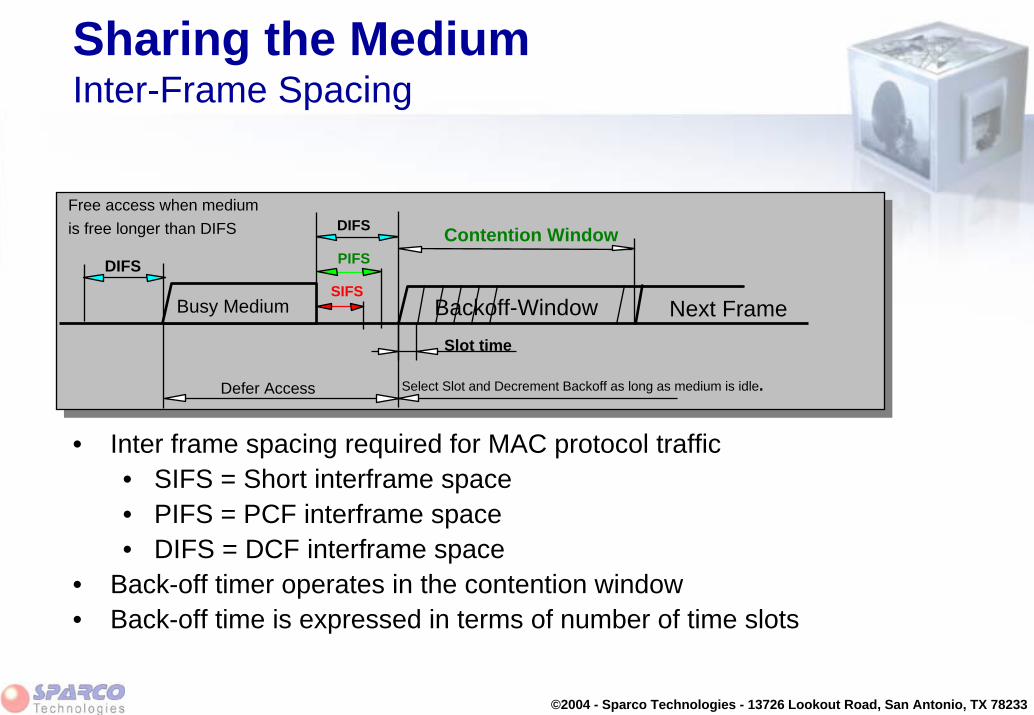
Sharing the MediumInter-Frame Spacing
DIFS Contention Window
Slot time
Defer Access
Backoff-Window Next Frame
Select Slot and Decrement Backoff as long as medium is idle.
SIFS
PIFSDIFS
Free access when mediumis free longer than DIFS
Busy Medium
• Inter frame spacing required for MAC protocol traffic• SIFS = Short interframe space• PIFS = PCF interframe space• DIFS = DCF interframe space
• Back-off timer operates in the contention window• Back-off time is expressed in terms of number of time slots

©2004 - Sparco Technologies - 13726 Lookout Road, San Antonio, TX 78233
Sharing the MediumCSMA/CA with Low-level Acknowledgment
Ack
Data
Next MPDU
Src
Dest
OtherContention Window
Defer Access Backoff after Defer
DIFS
SIFS
DIFS
• Collisions still can occur (interference; incapability of sensing other’s carrier)• IEEE 802.11 defines “low-level” ACK protocol• Provides faster error recovery• Makes presence of high level error recovery less critical
• Acknowledgment are to arrive at within the SIFS• The DCF interframe space is observed before medium is considered free
for use

©2004 - Sparco Technologies - 13726 Lookout Road, San Antonio, TX 78233
“Hidden Stations”The Problem
BA C
A sends to BC doesn’t detect that, so C might also start sending to BCollision of messages at B: both messages lost
• Situation that occurs in larger cells (typical outdoor)• Loss of performance
• Error recovery required

©2004 - Sparco Technologies - 13726 Lookout Road, San Antonio, TX 78233
“Hidden Stations”The Solution
A B
RTS: I want to send to B 500 bytes
CTS: OK A, go ahead, so everybody quiet
Data: the 500 bytes of data from A to B
ACK: B received the data OK, so an ACK
C
• IEEE 802.11 defines:• MAC level RTS/CTS protocol (Request to Send / Clear to Send) • Can be switched off to reduce overhead (when no hidden nodes exist)• More robustness, and increased reliability• No interruptions when large files are transmitted

©2004 - Sparco Technologies - 13726 Lookout Road, San Antonio, TX 78233
Message Fragmentation
• IEEE 802.11 defines:• MAC level function to transmit large messages as smaller frames
(user definable) • Improves performance in RF polluted environments• Can be switched off to avoid the overhead in RF clean environments
A hit in a large frame requires re-transmission of a large frameFragmenting reduces the frame size and the required time to re-transmit
Hit

©2004 - Sparco Technologies - 13726 Lookout Road, San Antonio, TX 78233
Multi-Channel Roaming
• Global IEEE 802.11 systems, support multi-channel roaming • Access points are set to a fixed frequency • Stations do not need to be configured for a fixed frequency• Stations switch frequency when roaming between access points• Stations “associate” dynamically to the access point with best signal,
on power on • This implies
• Easier configuration• Faster installation

©2004 - Sparco Technologies - 13726 Lookout Road, San Antonio, TX 78233
Multi-Channel Roaming
Channel 1
Channel 6
Channel 11
Channel 1

©2004 - Sparco Technologies - 13726 Lookout Road, San Antonio, TX 78233
Automatic Rate Select
• Global PC Card, dynamically switches data-rate• Fall back to lower data-rate when communications quality decreases
• out of range situations • Interference
• Fall-back scheme: • 11 Mbps, 5.5 Mbps, 2 Mbps, 1 Mbps
• This implies• Operating at larger distances• Robustness in RF polluted areas

©2004 - Sparco Technologies - 13726 Lookout Road, San Antonio, TX 78233
Automatic Rate Select
• Global PC Card in AP-500, AP-1000 and AP-2000 is capable of supporting different data-rates “simultaneously”:• e.g. operates at “High” speed in communication to nearby station and
at “Low” speed to station that is further away.• Data rate capability is maintained in “station association table”• Speed of IEEE Management - and Control frames use fixed speed
determined as “IEEE Basic Rates”, and controlled by “Multi-cast Rate parameter”.

©2004 - Sparco Technologies - 13726 Lookout Road, San Antonio, TX 78233
Cell Size / Multi Rate Applications
• Cell-size can be influenced by “Distance between APs” parameter:• Distance between APs = Large -> large cell• Distance between APs = Medium -> medium size cell• Distance between APs = Small -> small cell
• Cell-size influences capacity per station in the cell • small cell physically accommodates smaller number of stations than
large cell• bandwidth per station in small cell greater than in large cell
• Cell size influences data-rate• larger distance between station and access-point may lead to lower
data-rate

©2004 - Sparco Technologies - 13726 Lookout Road, San Antonio, TX 78233
Cell Size / Multi Rate Applications
• Mixture of cell-sizes accommodate mixed applications:• Office workers:
• High physical station density• High bandwidth requirement• Small cell operating at high data rate• Distance between APs is small
• Warehouse operations (such as forklift truck)• Low physical station density• Low bandwidth requirement (transaction processing)• Large cell operating at low data rate• Distance between APs is large

©2004 - Sparco Technologies - 13726 Lookout Road, San Antonio, TX 78233
Multi Rate Applications
1 Mbits/sec
11 Mbits/sec

©2004 - Sparco Technologies - 13726 Lookout Road, San Antonio, TX 78233
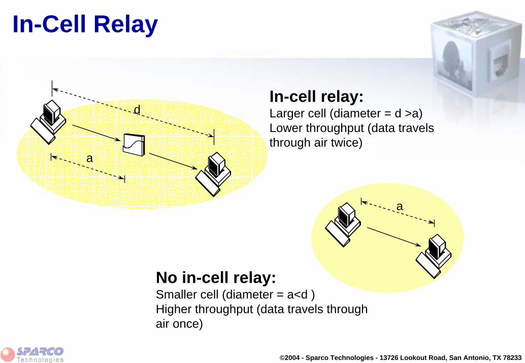
In-Cell Relay
• IEEE 802.11, in-cell relay:
• Single radio module when used in the AP-500, AP-1000 or AP-2000 acts as repeater between two stations
• Provides cells that are app. twice as large as cells without an access-point
• Communication flows via access-point so overall transmission time increases relative to pre-IEEE 802.11(or direct station to station communication)
• This implies:
• Larger cell size and consequently less need for access points and interconnecting infrastructure
• Reduced performance in peer to peer communication within one cell compared to AP-less cells
©2004 - Sparco Technologies - 13726 Lookout Road, San Antonio, TX 78233
In-Cell Relay
In-cell relay:Larger cell (diameter = d >a)Lower throughput (data travels through air twice)
No in-cell relay:Smaller cell (diameter = a<d )Higher throughput (data travels through air once)
d
a
a

©2004 - Sparco Technologies - 13726 Lookout Road, San Antonio, TX 78233
Power Management
• IEEE 802.11, supports power management:• nothing to send: station in sleep mode• out-bound traffic stored in Access Point (out-bound = from AP to STA)• station wake up only for Traffic Information Map (TIM)• if messages: stay awake to receive them
• This implies:• Prolonged battery life• Increase usability in hand-held equipment • Works best in application that have limited bandwidth requirements
(transaction processing)

©2004 - Sparco Technologies - 13726 Lookout Road, San Antonio, TX 78233
Wired Equivalent Privacy
• Optional security functionality (factory “installed”)• Encryption based on RC4 (1988 RSA algorithm)• Stream cipher 64 or 128 bits key
• User defined keys can be 40 or 104 bits long• 24 bits varying for each packet called the IV (Initialization vector)
• Used for data encryption• Used for shared key station authentication• Global’s FW inside the PC Card (implementing WEP) contains unique
protection against so-called “Weak Key” attacks• Sniffing (key capturing) programs such as Air Snort will are ineffective
in “stealing” encryption keys
©2004 - Sparco Technologies - 13726 Lookout Road, San Antonio, TX 78233
Wireless Distribution System
• IEEE 802.11, WDS means• Multiple (7) wireless “ports” inside the access-point for wireless
operations• 1 port can be assigned to connect Wireless Stations• Up to 6 ports can be used to connect wirelessly to other Access
Points• All done by one Global PC Card in the Access Point• All wireless links operate on the same channel
• WDS allows:• Extending the existing infrastructure with wireless backbone links• Totally wireless system without any wired backbones, needed in
locations where large areas are to be covered and wiring is not possible

©2004 - Sparco Technologies - 13726 Lookout Road, San Antonio, TX 78233
Wireless Distribution System
Channel 6
Channel 11
Channel 1

©2004 - Sparco Technologies - 13726 Lookout Road, San Antonio, TX 78233
IEEE 802.11 FeaturesModule Summary
• ACK protocol• Medium reservation (RTS/CTS)• Fragmentation• Multi-channel roaming• Automatic data-rate fall-back• Cell size / Multi-rate applications• In-cell relay• Power Management • Wired Equivalent Privacy (WEP)• Wireless Distribution System (WDS)

©2004 - Sparco Technologies - 13726 Lookout Road, San Antonio, TX 78233
IEEE 802.11 Architecture

©2004 - Sparco Technologies - 13726 Lookout Road, San Antonio, TX 78233
Module Contents
• IEEE 802.11 Terminology
• IEEE 802.11 MAC Frames
• Basic processes in IEEE802.11 networks
• Configuration parameters

©2004 - Sparco Technologies - 13726 Lookout Road, San Antonio, TX 78233
IEEE 802 .11 Terminology
Station (STA) Architecture:
• Device that contains IEEE 802.11 conformant MAC and PHY interface to the wireless medium, but does not provide access to a distribution system
• Most often end-stations available in terminals (work-stations, laptops etc.)
• Implemented in IEEE 802.11 PC-Card
Platform ComputerPlatform
Computer
PC-Card HardwarePC-Card HardwareRadio
Hardware
Radio Hardware
WMAC controller withStation Firmware
(WNIC-STA)
WMAC controller withStation Firmware
(WNIC-STA)
Driver Software(STADr)
Driver Software(STADr)
802.11 frame format
802.3 frame format
Ethernet V2.0 / 802.3frame format
Protocol StackProtocol Stack

©2004 - Sparco Technologies - 13726 Lookout Road, San Antonio, TX 78233
IEEE 802 .11 Terminology
Station (STA) Architecture (cont’d):
• Ethernet-like driver interface– supports virtually all protocol stacks
• Frame translation according to IEEE Std 802.1H– IEEE 802.3 frames: translated to 802.11– Ethernet Types 8137 (Novell IPX) and 80F3 (AARP)
encapsulated via the Bridge Tunnel encapsulation scheme
– All other Ethernet Types: encapsulated via the RFC 1042 (Standard for the Transmission of IP Datagrams over IEEE 802 Networks) encapsulation scheme
– Maximum Data limited to 1500 octets• Transparent bridging to Ethernet
Platform ComputerPlatform
Computer
PC-Card HardwarePC-Card HardwareRadio
Hardware
Radio Hardware
WMAC controller withStation Firmware
(WNIC-STA)
WMAC controller withStation Firmware
(WNIC-STA)
Driver Software(STADr)
Driver Software(STADr)
802.11 frame format
802.3 frame format
Ethernet V2.0 / 802.3frame format
Protocol StackProtocol Stack

©2004 - Sparco Technologies - 13726 Lookout Road, San Antonio, TX 78233
IEEE 802 .11 Terminology
Access-Point (AP) Architecture:
• Device that contains IEEE 802.11 conformant MAC and PHY interface to the wireless medium, and provide access to a distribution system for associated stations
• Most often infra-structure products that connect to wired backbones
• Implemented in IEEE 802.11 PC-Card when it is inserted in an AP-500 or AP-1000
BridgeSoftware
BridgeSoftware
PC-Card HardwarePC-Card HardwareRadio
Hardware
Radio Hardware
WMAC controller withAccess Point Firmware
(WNIC-AP)
WMAC controller withAccess Point Firmware
(WNIC-AP)
Driver Software(APDr)
Driver Software(APDr)
802.11 frame format
802.3 frame format
Ethernet V2.0 / 802.3frame format
Kernel Software (APK)Kernel Software (APK)
BridgeHardware
BridgeHardware
EthernetInterface
EthernetInterface

©2004 - Sparco Technologies - 13726 Lookout Road, San Antonio, TX 78233
IEEE 802 .11 Terminology
Access-Point (AP) Architecture (cont’d):
• Stations select an Access-Point and “associate with it
• Access-Points :– Support roaming– Provide time synchronization functions
(beaconing)– Provide Power Management support
• Traffic typically flows through Access-Point – in IBSS direct Station-to-Station
communication takes place
BridgeSoftware
BridgeSoftware
PC-Card HardwarePC-Card HardwareRadio
Hardware
Radio Hardware
WMAC controller withAccess Point Firmware
(WNIC-AP)
WMAC controller withAccess Point Firmware
(WNIC-AP)
Driver Software(APDr)
Driver Software(APDr)
802.11 frame format
802.3 frame format
Ethernet V2.0 / 802.3frame format
Kernel Software (APK)Kernel Software (APK)
BridgeHardware
BridgeHardware
EthernetInterface
EthernetInterface

©2004 - Sparco Technologies - 13726 Lookout Road, San Antonio, TX 78233
IEEE 802 .11 Terminology
Basic Service Set (BSS):
• A set of stations controlled by a single “Coordination Function” (=the logical function that determines when a station can transmit or receive)
• Similar to a “cell” in pre IEEE terminology
• A BSS can have an Access-Point (both in standalone networks and in building-wide configurations), or can run without and Access-Point (in standalone networks only)
• Diameter of the cell is app. twice the coverage-distance between two wireless stations

©2004 - Sparco Technologies - 13726 Lookout Road, San Antonio, TX 78233
Basic Service Set (BSS)
BSS

©2004 - Sparco Technologies - 13726 Lookout Road, San Antonio, TX 78233
IEEE 802 .11 Terminology
Independent Basic Service Set (IBSS):
• A Basic Service Set (BSS) which forms a self-contained network in which no access to a Distribution System is available
• A BSS without an Access-Point
• One of the stations in the IBSS can be configured to “initiate” the network and assume the Coordination Function
• Diameter of the cell determined by coverage distance between twowireless stations

©2004 - Sparco Technologies - 13726 Lookout Road, San Antonio, TX 78233
Independent Basic Service Set (IBSS)
IBSS

©2004 - Sparco Technologies - 13726 Lookout Road, San Antonio, TX 78233
IEEE 802 .11 Terminology
Extended Service Set (ESS):• A set of one or more Basic Service Sets interconnected by a Distribution
System (DS)• Traffic always flows via Access-Point• Diameter of the cell is double the coverage distance between two
wireless stations
Distribution System (DS):• A system to interconnect a set of Basic Service Sets
– Integrated; A single Access-Point in a standalone network– Wired; Using cable to interconnect the Access-Points– Wireless; Using wireless to interconnect the Access-Points

©2004 - Sparco Technologies - 13726 Lookout Road, San Antonio, TX 78233
Extended Service Set (ESS) Single BSS (with integrated DS)
BSS

©2004 - Sparco Technologies - 13726 Lookout Road, San Antonio, TX 78233
Extended Service Set (ESS) BSS’s with Wired Distribution System (DS)
BSS
BSS
Distribution
System

©2004 - Sparco Technologies - 13726 Lookout Road, San Antonio, TX 78233
Extended Service Set (ESS) BSS’s and Wireless Distribution System (DS)
BSS
BSS
Distribution
System

©2004 - Sparco Technologies - 13726 Lookout Road, San Antonio, TX 78233
IEEE 802 .11 Terminology
Service Set Identifier (SSID):
• “Network name”
• 32 octets long
• Similar to “Domain-ID” in the pre-IEEE WaveLAN systems
• One network (ESS or IBSS) has one SSID

©2004 - Sparco Technologies - 13726 Lookout Road, San Antonio, TX 78233
IEEE 802 .11 Terminology
Basic Service Set Identifier (BSSID)
• “cell identifier”
• 6 octets long (MAC address format)
• Similar to NWID in pre-IEEE WaveLAN systems
• One BSS has one SSID
• Value of BSSID is the same as the MAC address of the radio in the Access-Point

©2004 - Sparco Technologies - 13726 Lookout Road, San Antonio, TX 78233
Module Contents
• IEEE 802.11 Terminology
• IEEE 802.11 MAC Frames
• Basic processes in IEEE802.11 networks
• Configuration parameters

©2004 - Sparco Technologies - 13726 Lookout Road, San Antonio, TX 78233
Frame Formats
FrameControl
DurationID Addr 1 Addr 2 Addr 3 Addr 4Sequence
Control CRCFrameBody
2 2 6 6 6 62 0-2312 4
802.11 MAC Header
Bytes:
ProtocolVersion Type SubType To
DS Retry PwrMgt
MoreData WEP Rsvd
Frame Control Field
Bits: 2 2 4 1 1 1 1 1 1 1 1
DSFrom More
Frag
MAC Header format differs per Type:– Control Frames (several fields are omitted)– Management Frames– Data Frames

©2004 - Sparco Technologies - 13726 Lookout Road, San Antonio, TX 78233
Address Field Description
ProtocolVersion Type SubType To
DS Retry PwrMgt
MoreData WEP Rsvd
Frame Control Field
Bits: 2 2 4 1 1 1 1 1 1 1 1
DSFrom More
Frag
To DS0011
From DS0101
Address 1DADA
BSSIDRA
Address 2SA
BSSIDSATA
Address 3BSSID
SADADA
Address 4N/AN/AN/ASA
Addr. 1 = All stations filter on this address.Addr. 2 = Transmitter Address (TA), Identifies transmitter to address the ACK frame to.Addr. 3 = Dependent on To and From DS bits.Addr. 4 = Only needed to identify the original source of WDS (Wireless Distribution System) frames

©2004 - Sparco Technologies - 13726 Lookout Road, San Antonio, TX 78233
Type Field Descriptions
ProtocolVersion Type SubType To
DS Retry PwrMgt
MoreData WEP Rsvd
Frame Control Field
Bits: 2 2 4 1 1 1 1 1 1 1 1
DSFrom More
Frag
Type and subtype identify the function of the frame:• Type=00 Management Frame
Beacon (Re)AssociationProbe (De)Authentication Power Management
• Type=01 Control FrameRTS/CTS ACK
• Type=10 Data Frame
©2004 - Sparco Technologies - 13726 Lookout Road, San Antonio, TX 78233
MAC Management Frames
• Beacon– Timestamp, Beacon Interval, Capabilities, SSID, Supported
Rates, parameters– Traffic Indication Map
• Probe– SSID, Capabilities, Supported Rates
• Probe Response– Timestamp, Beacon Interval, Capabilities, SSID, Supported
Rates, parameters– same for Beacon except for TIM

©2004 - Sparco Technologies - 13726 Lookout Road, San Antonio, TX 78233
MAC Management Frames (cont’d)
• Association Request– Capability, Listen Interval, SSID, Supported Rates
• Association Response– Capability, Status Code, Station ID, Supported Rates
• Re-association Request– Capability, Listen Interval, SSID, Supported Rates, Current AP
Address
• Re-association Response– Capability, Status Code, Station ID, Supported Rates

©2004 - Sparco Technologies - 13726 Lookout Road, San Antonio, TX 78233
MAC Management Frames (cont’d)
• Dis-association– Reason code
• Authentication– Algorithm, Sequence, Status, Challenge Text
• De-authentication– Reason

©2004 - Sparco Technologies - 13726 Lookout Road, San Antonio, TX 78233
Module Contents
• IEEE 802.11 Terminology
• IEEE 802.11 MAC Frames
• Basic processes in IEEE802.11 networks
• Configuration parameters

©2004 - Sparco Technologies - 13726 Lookout Road, San Antonio, TX 78233
Operational ProcessesAssociation
• To establish relationship with Access-Point
• Stations scan frequency band to and select Access-Point with best communications quality– Active Scan (sending a “Probe request” on specific channels and
assess response)– Passive Scan (assessing communications quality from beacon
message)
• Access-Point maintains list of associate stations in MAC FW– Record station capability (data-rate)– To allow inter-BSS relay
• Station’s MAC address is also maintained in bridge learn table associated with the port it is located on

©2004 - Sparco Technologies - 13726 Lookout Road, San Antonio, TX 78233
Operational ProcessesAuthentication
• To control access to the infrastructure via an authentication
• Stations identify themselves to other stations (or Access-Points) prior to data traffic or association
• Open System Authentication– Uses null authentication algorithm– Default
• Shared Key Authentication – Uses WEP privacy algorithm– Optional

©2004 - Sparco Technologies - 13726 Lookout Road, San Antonio, TX 78233
Operational ProcessesStarting an ESS
• The infrastructure network is identified by its ESSID
• All Access-Points will have been set according to this ESSID
• Wireless stations will be configured to set their desired SSID to the value of ESSID
• On power up stations will issue Probe Requests and will locate the Access-Point that they will associate with:– “best” Access-Point with matching ESSID – “best” Access-Point if the “desired SSID” has been set to “ANY”

©2004 - Sparco Technologies - 13726 Lookout Road, San Antonio, TX 78233
Operational ProcessesStarting an IBSS
• Station configured for IBSS operation will:– “look” for Beacons that contain a network name (SSID) that matches
the one that is configured – When Beacons with matching Network Name are received and are
issued by an AP, Station will associate to the AP– When Beacons with matching Network Name are received and are
issued by another Station in IBSS mode, the station will join this IBSS– When no beacons are received with matching Network Name,
Station will issue beacons itself.• All Stations in an IBSS network will participate in sending beacons.
– All stations start a random timer prior to the point in time when next Beacon is to be sent.
– First station whose random timer expires will send the next beacon

©2004 - Sparco Technologies - 13726 Lookout Road, San Antonio, TX 78233
Operational ProcessesInter-Frame Spacing
DIFS Contention Window
Slot time
Defer Access
Backoff-Window Next Frame
Select Slot and Decrement Backoff as long as medium is idle.
SIFS
PIFSDIFS
Free access when mediumis free longer than DIFS
Busy Medium
• Inter frame spacing required for MAC protocol traffic– SIFS = Short interframe space– PIFS = PCF interframe space– DIFS = DCF interframe space
• Back-off timer expressed in terms of number of time slots

©2004 - Sparco Technologies - 13726 Lookout Road, San Antonio, TX 78233
Operational ProcessesData Frames and their ACK
Ack
Data
Next MPDU
Src
Dest
OtherContention Window
Defer Access Backoff after Defer
DIFS
SIFS
DIFS
• Acknowledgment are to arrive at within the SIFS• The DCF interframe space is observed before medium is
considered free for use

©2004 - Sparco Technologies - 13726 Lookout Road, San Antonio, TX 78233
Operational ProcessesTraffic flow - Inter-BSS
AP-1000 or AP-500AP-1000 or AP-500
PC- CardPC- Card
Association table
Inter- BSS Relay
Bridge learn table
STA- 1STA- 1
BSS-A
Associate
STA- 2STA- 2
AssociatePacket for STA- 2ACK Packet for STA- 2
ACK
STA- 1
STA- 1
2
STA- 2
STA- 2 2

©2004 - Sparco Technologies - 13726 Lookout Road, San Antonio, TX 78233
Operational ProcessesTraffic Flow - ESS Operation
STA- 1STA- 1 STA- 2STA- 2BSS-A
BSS-B
Backbone
Packet for STA- 2
ACK
Packet for STA- 2ACK
AP-1000 or AP-500AP-1000 or AP-500
PC- CardPC- Card
Association table
Bridge learn table
AP-1000 or AP-500AP-1000 or AP-500
PC- CardPC- Card
Association table
Bridge learn table
STA- 1
STA- 2 1
STA- 1
STA- 2
STA- 1
2 STA-2
2
1

©2004 - Sparco Technologies - 13726 Lookout Road, San Antonio, TX 78233
Operational ProcessesTraffic Flow - WDS Operation
STA- 1STA- 1 STA- 2STA- 2BSS-A
BSS-B
Packet for STA- 2
ACK
Packet for STA- 2ACK
AP-1000 or AP-500AP-1000 or AP-500
PC- CardPC- Card
Association table
Bridge learn table
AP-1000 or AP-500AP-1000 or AP-500
PC- CardPC- Card
Association table
Bridge learn table
STA- 1
STA- 2 2
STA- 1
STA- 2
STA- 1
2STA-
2
2
2
Wireless
Backbone
WDS Relay
WDS RelayPacket for STA- 2
ACK

©2004 - Sparco Technologies - 13726 Lookout Road, San Antonio, TX 78233
Module Contents
• IEEE 802.11 Terminology
• IEEE 802.11 MAC Frames
• Basic processes in IEEE802.11 networks
• Configuration parameters

©2004 - Sparco Technologies - 13726 Lookout Road, San Antonio, TX 78233
Configuration Parameters
PC-Card used in client station and AP-1000 or AP-500
• “Behaves” differently based on the parent unit– When inserted in AP-1000 or AP-500, AP firmware is downloaded into the PC-
Card (Note: this is /MAC FW, not “Bridge FW”)– When inserted in client station, STA firmware is active (default FW)
• Requires different configuration parameter sets to support the different behavior
• Configuration can be performed by:– Setting parameters at installation– Changing parameters in property settings– Using AP Manager (for APs)

©2004 - Sparco Technologies - 13726 Lookout Road, San Antonio, TX 78233
Configuration ParametersBasic Parameters (Station)
Network Name (SSID)• ASCII string to identify the network that the station wants to connect to
(similar to Domain-ID in WaveLAN pre-IEEE)
Station Name (SSID)• ASCII string to provide a user friendly station identification, when used in
diagnostic purposes (in Windows systems: equal to “computer name”)
Type of Operation• To identify the kind of network that the station will be part of
– Network centered around APs (or RG-1000)– IBSS (peer-to-peer network)

©2004 - Sparco Technologies - 13726 Lookout Road, San Antonio, TX 78233
Configuration ParametersAdvanced Parameters (Station)
MAC Address• Physical address of the card:
– Universal; factory installed (default)– Local; user-defined (6 Hexadecimal characters)
Distance between APs• To specify the coverage of a “cell” in terms of the distance between the
Access-Points– Large– Medium– Small

©2004 - Sparco Technologies - 13726 Lookout Road, San Antonio, TX 78233
Configuration ParametersAdvanced Parameters (Station)
Microwave Oven Robustness• Check box to enable/disable data-rate fallback delay-mechanism
to allow improved performance in presence of microwave ovens
RTS/CTS Medium Reservation• Check box to enable/disable the RTS/CTS handshake.
Card Power Management• Check box to enable/disable Power Management

©2004 - Sparco Technologies - 13726 Lookout Road, San Antonio, TX 78233
Configuration ParametersEncryption Parameters (Station)
Enable Encryption• To enable/disable Encryption
Encryption keys• Four fields to store up to four different encryption keys• Entries take up to 5 ASCII or 10 hexa-decimal values (when
using 64 WEP)
Encryption key index• Index identifying which of the four keys is the active one

©2004 - Sparco Technologies - 13726 Lookout Road, San Antonio, TX 78233
Configuration ParametersBasic Parameters (AP-500/1000)
Network Name (SSID)• ASCII string to identify the network that the Access-Point is
part of (similar to Domain-ID in WaveLAN pre-IEEE). Only available in “Access Point” mode.
Frequency (channel)• To indicate the frequency channel that the AP-500/1000 will
use for its “cell”. The channel is selected from the set that isallowed in the regulatory domain.

©2004 - Sparco Technologies - 13726 Lookout Road, San Antonio, TX 78233
Configuration ParametersAdvanced parameters (AP-500/1000)
Medium Reservation• To enable/disable the RTS/CTS handshake.
– Threshold value 0-2346 (value=2347 disables Medium Reservation)
Distance between APs• To specify the coverage of a “cell” in terms of the distance between the
Access-Points– Large– Medium– Small
Multicast Rate• To specify data-rate used for transmitting Multicast frames

©2004 - Sparco Technologies - 13726 Lookout Road, San Antonio, TX 78233
Configuration ParametersAdvanced parameters (AP-500/1000)
Microwave Oven Robustness• Check box to enable/disable data-rate fallback delay-mechanism to
allow improved performance in presence of microwave ovens
DTIM • Power Management related parameter to specify the timing of the
delivery of multicast traffic to stations that have indicated to receive multicast messages while under power management.Example:– DTIM=1 means multicast traffic when it arrives at the AP is passed
through after every beacon– DTIM=3 means multicast traffic is passed through after every 3rd
beacon message
©2004 - Sparco Technologies - 13726 Lookout Road, San Antonio, TX 78233
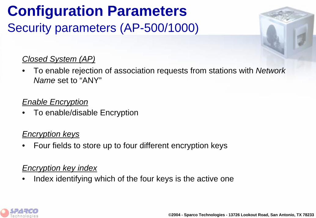
Configuration ParametersSecurity parameters (AP-500/1000)
Closed System (AP)• To enable rejection of association requests from stations with Network
Name set to “ANY”
Enable Encryption• To enable/disable Encryption
Encryption keys• Four fields to store up to four different encryption keys
Encryption key index• Index identifying which of the four keys is the active one

©2004 - Sparco Technologies - 13726 Lookout Road, San Antonio, TX 78233
Configuration ParametersFor Future Implementation
Message Fragmentation (STA and AP)• To enable/disable fragmentation of messages. When enabled user is
prompted to set the fragment-size (256-2346). Default: fragmentation disabled
• Microwave Oven (threshold = 500)• Medium Velocity (15 km/h) (threshold = 800)• High Velocity (30 km/h) (threshold = 300)
WDS Address (AP)• MAC address of the corresponding AP in a WDS link

©2004 - Sparco Technologies - 13726 Lookout Road, San Antonio, TX 78233
Module Contents
• IEEE 802.11 MAC Frames
• IEEE 802.11 Terminology
• Basic processes in IEEE802.11 networks
• Configuration parameters

©2004 - Sparco Technologies - 13726 Lookout Road, San Antonio, TX 78233
System Performance

©2004 - Sparco Technologies - 13726 Lookout Road, San Antonio, TX 78233
Module Contents
• Overview
• Data-rate
• Throughput
• Response times
• Capacity
• Power consumption

©2004 - Sparco Technologies - 13726 Lookout Road, San Antonio, TX 78233
Overview
Performance means different things depending on application and user interest:
– Data-rate - Raw bit rate, comparison purposes, technology oriented • What is maximum speed that the technology allows?
– Throughput - File transfer time, real-life practice, office automation• How long does it take to transfer files?
– Response times - Transaction handling, includes more than just transfer time• how long does it take to complete a transaction?
– Capacity - Sharing bandwidth among users• How many stations can coexist in one cell?
– Power consumption - Battery operated equipment • How long will the battery last?

©2004 - Sparco Technologies - 13726 Lookout Road, San Antonio, TX 78233
Overview
Performance expectations differ per application:
• Transaction processing– Require fast responses (same as wired LAN)– Characterized by short message (impose low network load)– Raw data-rate is of limited important (as long as network load stays
low)
• Office Automation– response times less critical– medium to high network load – network capacity is key aspect to keep under control
©2004 - Sparco Technologies - 13726 Lookout Road, San Antonio, TX 78233
Overview
Performance expectations differ per application:
• Multimedia– Require un-interrupted execution of multimedia files (movie clips)– Characterized by large files – Raw data-rate and capacity are critical (need to be maximized)
• CAD/CAM– Characterized by large files– High network load – Need for capacity is critical (need to be maximized)

©2004 - Sparco Technologies - 13726 Lookout Road, San Antonio, TX 78233
Module Contents
• Overview
• Data-rate
• Throughput
• Response times
• Capacity
• Power consumption

©2004 - Sparco Technologies - 13726 Lookout Road, San Antonio, TX 78233
Data-Rate
• Data-rate (or bit-rate) expressed in Mbit/s• Relates to the data only (not the preamble) • Determined by technology:
– DBPSK - 1 Mbps– DQPSK - 2 Mbps– CCK - 5.5/11 Mbps
• MAC Management frames and multicast frames are xmitted at lower data-rate to be able to reach stations with different speed capabilities
– Multi-cast traffic can be configured to high speed (in the AP), in combination with the cell-size (=distance between APs).

©2004 - Sparco Technologies - 13726 Lookout Road, San Antonio, TX 78233
Data RateAuto Fallback
Auto Rate Select – Start at highest possible data-rate (= 11 Mbps)– Fall-back to next lower data-rate
• when 2 subsequent transmissions fail (ACKs missed)– Upgrade to next higher data-rate
• after 10 successful transmissions (ACKs)• after 10 seconds• try next higher data-rate
–if fails, go back to “Low”–if successful, go to normal rate
– AP follows STA

©2004 - Sparco Technologies - 13726 Lookout Road, San Antonio, TX 78233
Module Contents
• Overview
• Data-rate
• Throughput
• Response times
• Capacity
• Power consumption

©2004 - Sparco Technologies - 13726 Lookout Road, San Antonio, TX 78233
Throughput
• Typically expressed in Kbytes/sec • Throughput lower than bit-rate due to
– IEEE 802.11 Management & Control frames xmit at lower data rate – Contention window (required to avoid collisions)– Inter-frame spacing in the media – Sources of interference– Network Operating System overhead (protocol stacks)– Other users that share the media
• Throughput as perceived by users differ also due to– Path between station and access point (need for re-transmissions)
• Distance• Environment (walls, sources of interference)
– File size– Additional security solutions such as WEP and VPN tunnels

©2004 - Sparco Technologies - 13726 Lookout Road, San Antonio, TX 78233
ThroughputImpact of IEEE 802.11 MAC

©2004 - Sparco Technologies - 13726 Lookout Road, San Antonio, TX 78233
ThroughputImpact of IEEE 802.11 MAC

©2004 - Sparco Technologies - 13726 Lookout Road, San Antonio, TX 78233
ThroughputDepends on Configuration
Data rate (11 Mbps)
IBSS (station to station) 5.04
Single BSS (station to station via WP)
ESS (wireless station to wired
station)
Source: Testing at WCND using WhatsUpGold throughput test (packet size = 8192 Bytes)
11 Mbps 5.5 Mbps 2 Mbps 1 Mbps
3.44 1.59 0.87
2.85
4.66
All values are in Mbps
• Throughput in Single BSS lower than IBSS or ESS as result of intra-cell relay function (traffic travels twice through the medium, invoking defers as part of CSMA/CA)

©2004 - Sparco Technologies - 13726 Lookout Road, San Antonio, TX 78233
ThroughputDepends on Protocol Stacks
Measurements using WaveLAN at 2 Mbit/sec
Protocol Measured Throughput
NETBEUI 180 Kbytes/sec
TCP/IP 144 Kbytes/sec
IPX/SPX 155 Kbytes/sec
1.44 Mbit/sec
1.15 Mbit/sec
1.24 Mbit/sec
Source: Testing at WCND

©2004 - Sparco Technologies - 13726 Lookout Road, San Antonio, TX 78233
ThroughputDepends on number of stations in cell
Measurements using WaveLAN at 2 Mbit/secNumber of
stations Measured Throughput
2 177 Kbytes/sec 1.42 Mbit/sec3 177 Kbytes/sec 1.42 Mbit/sec4 167 Kbytes/sec 1.34 Mbit/sec5 166 Kbytes/sec 1.33 Mbit/sec6 160 Kbytes/sec 1.28 Mbit/sec7 159 Kbytes/sec 1.27 Mbit/sec
Source: Testing at WCNDFile size: 10 KbytesProtocol: IPX/SPX

©2004 - Sparco Technologies - 13726 Lookout Road, San Antonio, TX 78233
ThroughputDepends on File Size
Measurements using WaveLAN at 2 Mbit/sec
File size Measured Throughput
100 Kbytes 236 Kbytes/sec
500 Kbytes 184 Kbytes/sec
1 Mbytes 181 Kbytes/sec
1.88 Mbit/sec
1.47 Mbit/sec
1.44 Mbit/sec
Source: Canterbury Christ Church CollegeNumber of stations: 1Protocol: TCP/IP
©2004 - Sparco Technologies - 13726 Lookout Road, San Antonio, TX 78233
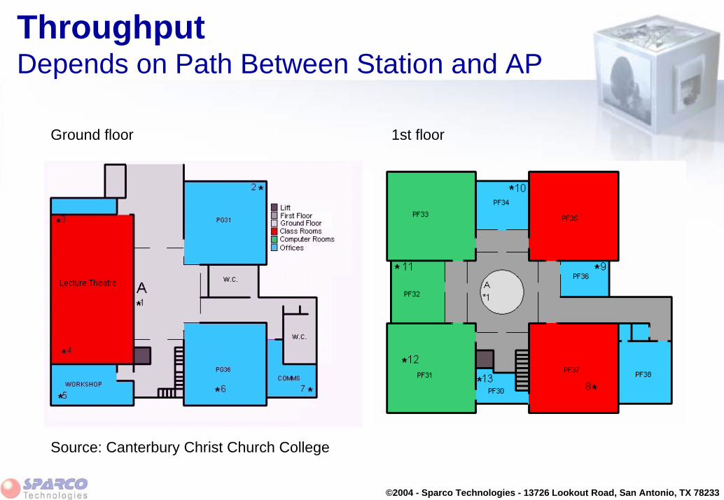
ThroughputDepends on Path Between Station and AP
Ground floor 1st floor
Source: Canterbury Christ Church College

©2004 - Sparco Technologies - 13726 Lookout Road, San Antonio, TX 78233
ThroughputDepends on Path Between Station and AP
Measurements using WaveLAN at 2 Mbit/secPosition Measured Throughput
1 206 Kbytes/sec 1.65 Mbit/sec2 204 Kbytes/sec 1.63 Mbit/sec3 200 Kbytes/sec 1.60 Mbit/sec4 202 Kbytes/sec 1.62 Mbit/sec5 202 Kbytes/sec 1.62 Mbit/sec6 202 Kbytes/sec 1.62 Mbit/sec7 200 Kbytes/sec 1.60 Mbit/sec8 163 Kbytes/sec 1.30 Mbit/sec9 182 Kbytes/sec 1.45 Mbit/sec10 200 Kbytes/sec 1.60 Mbit/sec11 201 Kbytes/sec 1.61 Mbit/sec12 199 Kbytes/sec 1.59 Mbit/sec13 200 Kbytes/sec 1.60 Mbit/sec
Source: Canterbury Christ Church CollegeNumber of stations: 1File size(s): 100 Kbytes, 500 Kbytes, 1 Mbytes (measurements are averages)Protocol: TCP/IP

©2004 - Sparco Technologies - 13726 Lookout Road, San Antonio, TX 78233
Module Contents
• Overview
• Data-rate
• Throughput
• Response times
• Capacity
• Power consumption

©2004 - Sparco Technologies - 13726 Lookout Road, San Antonio, TX 78233
Response Times
• Typically expressed in seconds
• Key aspect in transaction processing
• Network load is small (short messages)
• Depends less on factors that determine throughput – Network Operating System overhead (protocol stacks)– Other users that share the media– Inter-frame spacing in the media– path between station and access point (need for re-transmissions)
• But more on server application– Time it takes to turn around of the transaction-request

©2004 - Sparco Technologies - 13726 Lookout Road, San Antonio, TX 78233
Response Times
Response Tim es(seconds)
0
2
4
6
8
10
12
4 KByte 50 KByte 350 KByte 800 KByte
WaveLA N
TR 4 MBps
Eth 10 MBps
4 Kbytes
WaveLAN 0.14
Token Ring 0.14
Ethernet 0.11
50 Kbytes
0.53
0.54
0.30
350 Kbytes
3.70
3.60
1.80
800 Kbytes
10.4
8.60
5.11

©2004 - Sparco Technologies - 13726 Lookout Road, San Antonio, TX 78233
Module Contents
• Overview
• Data-rate
• Throughput
• Response times
• Capacity
• Power consumption

©2004 - Sparco Technologies - 13726 Lookout Road, San Antonio, TX 78233
Capacity
Number of stations per “radio-cell” depends on
• Bandwidth requirements per station– user profile
• Available bandwidth per cell– net capacity per cell depending on protocol and path : 1.1 - 1.8 Mbit/sec (for a
2 Mbit/sec data rate)– maximum data-rate (11 Mbit/sec maximum)
• Dimension (coverage) of the cell
• Number of co-located cells– can be increased by using additional channels

©2004 - Sparco Technologies - 13726 Lookout Road, San Antonio, TX 78233
CapacityBandwidth Requirements
Differ per application:
• Transaction processing– < 8 Kbit/sec
• Office Automation– < 64 Kbit/sec (depending on user profile)
• Multimedia– 100-800 Kbit/sec
• CAD/CAM– >1.5 Mbit/sec

©2004 - Sparco Technologies - 13726 Lookout Road, San Antonio, TX 78233
CapacityOffice Automation User Profiles
• Single cell
• Raw cell capacity : 2 Mbit/sec
• User profiles:
– Light user• 16 Kbit/sec
– Medium user• 32 Kbit/sec
– Heavy user• 64 Kbit/sec
0102030405060708090 80
40
20
LightUser
(2 KBps)
MediumUser
(4 KBps)
HeavyUser
(8 KBps)
Simultaneous Office Automation Users

©2004 - Sparco Technologies - 13726 Lookout Road, San Antonio, TX 78233
CapacityDimension of the Cell
• Cell size scaling
• Changes carrier detect and defer thresholds– Carrier Detect threshold - indication for station to accept/reject signal– Defer threshold - indication to station to defer for transmission from other
station in the cell
• Expressed in terms of “Distance between APs”– Large– Medium– Small
• Cell size to match application:– small cell for high band width high capacity– Large cell for low bandwidth low capacity

©2004 - Sparco Technologies - 13726 Lookout Road, San Antonio, TX 78233
CapacityDimension of the Cell
“Distance between AP” parameter settingSmall Medium Large
Cost impact
Cell diameter (open office)
Carrier detectthreshold
Defer threshold
Highest
~ 60 meter
- 85 dBm
- 75 dBm
Less
~ 90 meter
- 90 dBm
- 85 dBm
Lowest
> 100 meter
- 95 dBm
- 95 dBm

©2004 - Sparco Technologies - 13726 Lookout Road, San Antonio, TX 78233
CapacityMulti-channel Networks
• 802.11b radios operate in 2.4 GHz ISM band 2400-2483.5 MHz, but require a frequency band of app. 22 MHz

©2004 - Sparco Technologies - 13726 Lookout Road, San Antonio, TX 78233
CapacityMulti-channel Networks
Regulatory domain defines allowed channel set:
Channel ID ETSIFCC France Japan1 24122412 -2 24172417 -3 24222422 -4 24272427 -5 24322432 -6 24372437 -7 24422442 -8 24472447 -9 24522452 -10 24572457 2457
12 2467- 246713 2472- 247214 -- - 2484
11 24622462 2462
2412241724222427243224372442244724522457
24672472
2462

©2004 - Sparco Technologies - 13726 Lookout Road, San Antonio, TX 78233
12412
2401 2423
22417
2406 2428
32422
2411 2433
42427
2416 2438
52432
2421 2443
62437
2426 2448
72442
2431 2453
82447
2436 2458
92452
2441 2463
102457
2446 2468
112462
2451 2473
122467
2456 2478
132472
2461 2483
ISM Band 2484 MHz2400 MHz
Channel number
Top of channel
Center frequency
Bottom of channel
CapacityMulti-channel Networks - ETS

©2004 - Sparco Technologies - 13726 Lookout Road, San Antonio, TX 78233
CapacityMulti-channel Networks - FCC
12412
2401 2423
22417
2406 2428
32422
2411 2433
42427
2416 2438
52432
2421 2443
62437
2426 2448
72442
2431 2453
82447
2436 2458
92452
2441 2463
102457
2446 2468
112462
2451 2473
2400 MHz 2484 MHzISM Band
Channel number
Top of channel
Center frequency
Bottom of channel

©2004 - Sparco Technologies - 13726 Lookout Road, San Antonio, TX 78233
CapacityMulti-channel Networks
• Multiple channels within 2.4 GHz band, can be used based on regulatory domain
– ETS (most of Europe, Australia, ..): 1 .. 3 channels
– North America: 1 .. 3 channels
– World: 1 .. 3 channels
– Japan: 1 .. 3 channels
– France: single channel

©2004 - Sparco Technologies - 13726 Lookout Road, San Antonio, TX 78233
CapacityMulti-channel Networks
• Network Capacity can be increased by using different channels (by co-locating or stacking cells):– Multiple APs covering the same area but using different frequencies.– Can lead to capacity increase of factor 3-4 depending on proper AP
placement, and allowable channels
• Warning: – Use multiple channels only when there is a need for additional capacity. – If extra capacity is not needed, select one channel for the complete network
and choose the channel that has least interference

©2004 - Sparco Technologies - 13726 Lookout Road, San Antonio, TX 78233
CapacityMulti-channel Networks
AP-1 AP-2
AP-3
• Three APs (identified by a colored star) cover a rectangular area (e.g. Class room)– AP-1 set to channel 1– AP-2 set to channel 6– AP-3 set to channel 11
• 25 stations in the class room (represented by colored dots) associate to one of the APs

©2004 - Sparco Technologies - 13726 Lookout Road, San Antonio, TX 78233
Performance Impacting FactorsMulti-channel Networks - Channel Separation
• Using two PC Cards in one AP-1000 requires:– One PC Card to be
connected to a range extender
– two channel systems (versus three channel systems shown earlier
ETSI DomainAdapter-1’s Adapter-2’s Channel #Channel #
1 2 3 4 5 6 7 8 9 10 11 12 13
1
2
3
4
5
6
7
8
9
10
11
12
13
Note: a symbol indicates a channel combination that can be used.

©2004 - Sparco Technologies - 13726 Lookout Road, San Antonio, TX 78233
CapacityMulti-channel Networks - Near-far Behavior
d3d1
d2Access Point A
Access Point B
Station A
Station B
• Impact of physically nearby station that operates in different channel
• Seen as interference - no defer
• Minimum distances need to be observed to allow good operation
Channel 4 Channel 5 Channel 6
Station-B’s channel
Channel 3 Channel 7Channel 1
Distance d3
Station-A’s channel
1-4 meter 1-2.5 meter 1-2 meter5-10 meter 1-1.5 meter
d1 = d2 = 20 meter

©2004 - Sparco Technologies - 13726 Lookout Road, San Antonio, TX 78233
Module Contents
• Overview
• Data-rate
• Throughput
• Response times
• Capacity
• Power consumption

©2004 - Sparco Technologies - 13726 Lookout Road, San Antonio, TX 78233
Power Consumption
Power consumption can be reduced by Standard 802.11 Power Save Mode:
• Improves battery life
• Impacts throughput
• Not recommended for all applications

©2004 - Sparco Technologies - 13726 Lookout Road, San Antonio, TX 78233
Power ConsumptionHow Power Management Works
• Station under Power Management can be in two states:– Awake– Doze (sleep)
• Traffic to be transmitted to the station is buffered by the Access-Point, when station is in doze state
• Station wakes for (nth) Beacon and examines TIM (TIM = Traffic Indication Map), which is inside Beacon
• When traffic is present station polls the Access-Point for each buffered frame
• When station needs to transmit it wakes up for transmission, and goes back to sleep immediately

©2004 - Sparco Technologies - 13726 Lookout Road, San Antonio, TX 78233
Power ConsumptionHow Power Management Works
• Station can be configured to receive multi-cast messages
• Access-Point will buffer multi-cast traffic and send it following a DTIM (=Delivery Traffic Information Message) inside the Beacon
• DTIM interval can be configured at the Access-Point in terms of # of beacons between subsequent DTIM messages:– e.g every nth beacon (where n is user configuration parameter)
©2004 - Sparco Technologies - 13726 Lookout Road, San Antonio, TX 78233
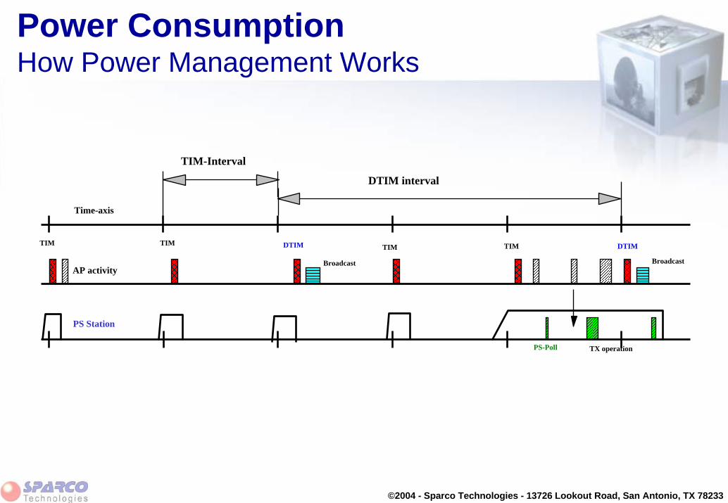
Power ConsumptionHow Power Management Works
TIM-Interval
TX operation
PS Station
PS-Poll
TIM
Time-axis
AP activity
TIM TIM TIM DTIMDTIM
DTIM interval
BroadcastBroadcast

©2004 - Sparco Technologies - 13726 Lookout Road, San Antonio, TX 78233
Power ConsumptionImpact of Power Management
• Improves battery life
• Reduced amount of power consumed by the network card– Overall battery life improvement more significant when network
card’s power consumption represent large portion of total– Overall battery life improvement insignificant when platform station
consumes substantial amount of power for non-network elements
• Impacts throughput– Transmission of large files will suffer from reduced performance– Transaction oriented processing will not perceive performance impact

©2004 - Sparco Technologies - 13726 Lookout Road, San Antonio, TX 78233
Power ConsumptionImpact of Power Management
• Platform that consumes more power for other elements– Disk– Screen– Memory
90 % 10 %
50 % reduction in PC Card’s power consumption
50 %
10 % reduction in overall system power consumption
Basic platform elements (80%) PC Card (20%)
©2004 - Sparco Technologies - 13726 Lookout Road, San Antonio, TX 78233
Power ConsumptionImpact of Power Management
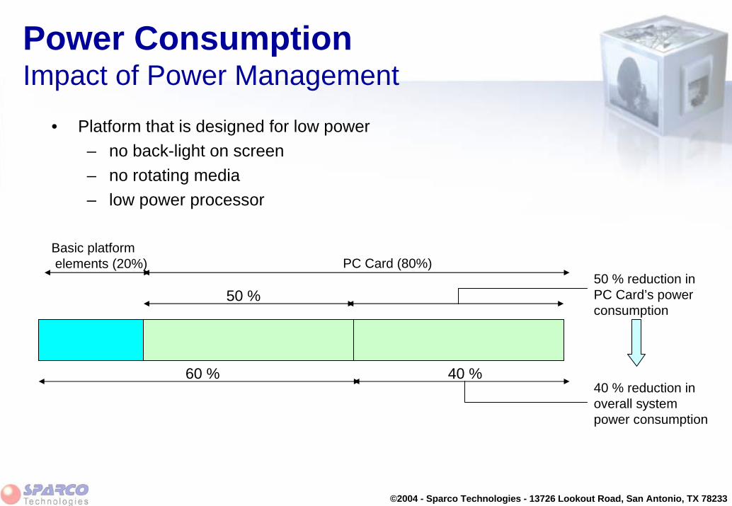
• Platform that is designed for low power– no back-light on screen– no rotating media– low power processor
Basic platformelements (20%) PC Card (80%)
60 % 40 %
50 % reduction in PC Card’s power consumption
50 %
40 % reduction in overall system power consumption

©2004 - Sparco Technologies - 13726 Lookout Road, San Antonio, TX 78233
Power ConsumptionImpact of Power Management
• Throughput measurements on notebook computer• Large file (7.01 Mbytes) transmission)
Network disk to Notebook
Notebook to network disk
With Power Management 213 sec
Without PowerManagement 62 sec
422 sec
89 sec
AverageBattery life
128 minutes
102 minutes

©2004 - Sparco Technologies - 13726 Lookout Road, San Antonio, TX 78233
Power ConsumptionApplicability of Power Management
Performance decrease (%)
Bat
tery
life
incr
ease
(%)
Hand-held data
terminals (scanners)
PDAs under
Windows/CE
Notebook (light load
on network)
Notebook (medium load on network)
Notebook (heavy load on network)
Sub-Notebook

©2004 - Sparco Technologies - 13726 Lookout Road, San Antonio, TX 78233
Roaming

©2004 - Sparco Technologies - 13726 Lookout Road, San Antonio, TX 78233
Module Contents
• Scan
• Sweep
• Association
• Authentication
• Roaming
©2004 - Sparco Technologies - 13726 Lookout Road, San Antonio, TX 78233
Scan
• Access-Point and Station need to be established on same frequency in order to communicate
• Access-Points operate on a fixed frequency (selected from an allowed set of channels)
• Stations dynamically “tune” the radio to the channel of the Access-Point
• Process is called Scanning

©2004 - Sparco Technologies - 13726 Lookout Road, San Antonio, TX 78233
Scan
IEEE 802.11 defines two methods:
• Passive Scanning– Station switches to a given channel and listens for incoming beacons from
Access-Point
• Active Scanning– Station switches to a given channel and issues a “Probe Request”– Access-Point replies with a “Probe Response”

©2004 - Sparco Technologies - 13726 Lookout Road, San Antonio, TX 78233
Module Contents
• Scan
• Sweep
• Association
• Authentication
• Roaming

©2004 - Sparco Technologies - 13726 Lookout Road, San Antonio, TX 78233
Sweep
• A series of scans on different channels is called a “Sweep”
• A Sweep uses a “channel-list” that contains the channels to scan
• There are two type of sweeps:
– “Full Sweep”• All channels in the “channel-list” are scanned
– “Short Sweep”• A sub-set of the “channel-list” is used to perform the scan

©2004 - Sparco Technologies - 13726 Lookout Road, San Antonio, TX 78233
Sweep
“Short Sweep” will speed up the roaming process• Subset of channel lists contains
– Active channels• Channels that have been found to be used before since the station has
been switched on– Most likely channels
• Channels that have likely channel separation from active channels (more than two channels away from active one)
• Example: If channel 5 is active, channel 2 and 8 are likely. Channel 3, 4, 6 and 7 are unlikely as they are to close to channel 5 and will not be scanned

©2004 - Sparco Technologies - 13726 Lookout Road, San Antonio, TX 78233
Module Contents
• Scan
• Sweep
• Association
• Authentication
• Roaming

©2004 - Sparco Technologies - 13726 Lookout Road, San Antonio, TX 78233
Association
Station that needs connection to a network initiates “Initial Association” sequence:
– Execute a full sweep– Select AP with best communications quality, that matches the value
for “network name” (= SSID). • If “network name” set to “ANY” and Access-Point is not set to “closed”
– Station send “Association Request”– AP enters the Station in its Association Table (and assigns an
“Association Code” to it)

©2004 - Sparco Technologies - 13726 Lookout Road, San Antonio, TX 78233
Association
AP-1000 or AP-500AP-1000 or AP-500
ORiNOCO PC- CardORiNOCO PC- Card
Association table
Inter- BSS Relay
Bridge learn table
STA- 1STA- 1
BSS-A
Associate
STA- 2STA- 2
Associate
STA- 1
STA- 1
2
STA- 2
STA- 2 2

©2004 - Sparco Technologies - 13726 Lookout Road, San Antonio, TX 78233
Module Contents
• Scan
• Sweep
• Association
• Authentication
• Roaming

©2004 - Sparco Technologies - 13726 Lookout Road, San Antonio, TX 78233
Authentication
• Stations authenticate at each Access-Point once before their first association to the Access-Point
• A roaming station may need to re-authenticate at the Access-Point that it is roaming to, even though it has been authenticated by the Access Point it roams away from future implementations of IAPP will pass authentication information as part of the hand-over protocol

©2004 - Sparco Technologies - 13726 Lookout Road, San Antonio, TX 78233
Authentication
• Authentication schemes (will be explained in module on security):
– IEEE 802.11 defined:• Open System Authentication• Shared Key Authentication (based on WEP)
– RADIUS Based MAC authentication• Based on MAC address of PC Card registered in
centrally kept Access Control list

©2004 - Sparco Technologies - 13726 Lookout Road, San Antonio, TX 78233
Module Contents
• Scan
• Sweep
• Association
• Authentication
• Roaming

©2004 - Sparco Technologies - 13726 Lookout Road, San Antonio, TX 78233
RoamingCommunications Quality
• Key indicator of to assess path between Station and Access-Point
• Determined by:
– SNR (Signal to Noise Ratio) on path with current Access-Point:
• Running Average Signal Level from Beacon receptions• Running Average Noise Level from all receptions in current
channel
– Result of Sweep (when Searching):• SNR of Probe Responses

©2004 - Sparco Technologies - 13726 Lookout Road, San Antonio, TX 78233
RoamingCommunications Quality
Highest Quality
Lowest Quality
Cell Search ThresholdCQ
Out Of Range Threshold
Not Searching (NS) zone
Cell Search (CS) zone
Out of Range (OR) zone
• Station monitors the communications quality (CQ) of the link to “its” Access-Point
• When station moves away from Access-Point the CQ drops decreases
• When CQ drops below a set threshold value the Station enters Cell-Search state

©2004 - Sparco Technologies - 13726 Lookout Road, San Antonio, TX 78233
RoamingCell Search State
Station ...• Informs current AP to buffer traffic during Sweep (PM
buffering)• Blocks its own transmissions during Sweep• Scans Multiple Channels
– limited to Active (or Likely-to-be-Active) Channels– learns during sweeps
• 3 channels on each side of an Active channel are considered “NotLikely”
• Uses Active Scanning (Probe Requests)• Takes 5 .. 50 ms per Channel (depending on activity)

©2004 - Sparco Technologies - 13726 Lookout Road, San Antonio, TX 78233
RoamingSwitching to new Access-Point
• Switching based on “delta-SNR”:
– SNR of Probe Responses compared to SNR current Access-Point
• When CQ drops below “Cell Search Threshold” new Access-Point should already been identified
• Station also enters “cell-search” when it misses 4 or more Beacons in a row:
– Busy cell– Form of load balancing

©2004 - Sparco Technologies - 13726 Lookout Road, San Antonio, TX 78233
RoamingOut of Range Condition• When no Access-Point present
acceptable to station:– Station will stay associated– Station will fall back to lower
bit-rate– Eventually loss of
association
• Out of Range Threshold is Carrier Detect Threshold (influenced by AP Density parameter)
• Station will scan all channels in full sweep every 10 seconds (versus short sweep in Cell Search Mode)

©2004 - Sparco Technologies - 13726 Lookout Road, San Antonio, TX 78233
RoamingHand-over
Station …
– First retrieves buffered frames from current Access-Point– Then re-associates with new Access-Point
Access Point …
– Uses Inter Access Point Protocol (IAPP)• over the Distribution System that connects the APs• to inform old Access-Point of the event and allow it to change the
association table• to update filter tables in intermediate bridges• IAPP uses UDP/IP, so works over routers, but …..
roaming over routers requires Mobile IP– Old Access-Point dumps (remaining) buffered frames for STA

©2004 - Sparco Technologies - 13726 Lookout Road, San Antonio, TX 78233
Roaming and IAPP
IAPP protocol elements:
• WMP (WaveLAN Management Protocol) Station Announce – one-directional protocol to signal a re-association of a mobile station
• Announce Protocol– Protocol used by an AP to identify itself to other APs and to obtain
information on other APs in the same area
• Hand-over Protocol– bi-directional message exchange between AP’s when initiated when
a mobile station re-associates

©2004 - Sparco Technologies - 13726 Lookout Road, San Antonio, TX 78233
IAPPWMP Station Announce
• At hand-over, a message is sent from new AP to old AP, using the MAC address of the mobile station as Source Address
• Causes bridges and switches in between the two APs to learn that the mobile station has changed location and these bridges will update their tables accordingly
• Some switches may act differently and reflect the movement of the mobile station as an address violation
APBridge
AP
STA
Hand- over Messagewith STA source address
Re- association
port1 port2

©2004 - Sparco Technologies - 13726 Lookout Road, San Antonio, TX 78233
IAPPAnnounce Protocol
AP-1AP-1 All APs
Announce RequestAnnounce Request
Announce ResponseAnnounce Response
Announce ResponseAnnounce Response
Announce ResponseAnnounce Response
1.
2.
3.
4.
1. At startup AP transmits a so-called "Announce request” (IP Multicast Destination Address) using defined UDP/IP group addressing.
2. APs that are part of the same network and are already operational will respond with a so-called "Announce response”, containing:– IP address of the replying AP– BSSID of the replying AP

©2004 - Sparco Technologies - 13726 Lookout Road, San Antonio, TX 78233
IAPPAnnounce Protocol (cont’d)
AP-1AP-1 All APs
Announce RequestAnnounce Request
Announce ResponseAnnounce Response
Announce ResponseAnnounce Response
Announce ResponseAnnounce Response
1.
2.
3.
4.
3. The new AP uses the data in the reply to build a BSSID-to-IP conversion table to relate the BSSID, (used by the roaming station to identify its "old" AP) to the IP address of the "old" AP
Future implementations will carry information, such as
• the name of the AP, to be used to identify APs in the "Site Monitor" display
• authorization information regarding the mobile station in case a centrally based Authentication scheme is used.

©2004 - Sparco Technologies - 13726 Lookout Road, San Antonio, TX 78233
IAPPAnnounce Protocol (cont’d)
AP-1AP-1 All APs
Announce RequestAnnounce Request
Announce ResponseAnnounce Response
Announce ResponseAnnounce Response
Announce ResponseAnnounce Response
1.
2.
3.
4.
4. After an appropriate time interval, when all responses are received, the "new" AP will issue an "Announce response" to indicate its operational status.– The "new" AP will (as will all APs)
re-issue the "Announce response" to keep informing all participating APs about any changes in the status.

©2004 - Sparco Technologies - 13726 Lookout Road, San Antonio, TX 78233
IAPPHand-over Protocol
MobilestationMobilestation
New AP
Re-associationRequest
Re-associationRequest
Re-associationResponse
Re-associationResponse
1.
2.3.
4.
Old AP
Handover RequestHandover Request
IEEE 802.11 IAPP
Handover ResponseHandover Response

©2004 - Sparco Technologies - 13726 Lookout Road, San Antonio, TX 78233
IAPPHand-over Protocol (cont’d)
1. When the mobile station moves away from its "old" AP, it issues a Re-associate Request to a "new" AP,
2. The "new" AP will return a Re-association Response when it accepts the roaming station. The AP service for the mobile station starts at this point in time
3. The "new" AP sends a Hand-over Request to the old AP (via the Distribution System). IP address of old AP is determined based on BSSID carried in the Re-association Request
4. When the Hand-over Response received, the hand-over is considered to be completed.

©2004 - Sparco Technologies - 13726 Lookout Road, San Antonio, TX 78233
Mobility and Existing NetworksRoaming over Routers
• Mobility has more impact, since MAC level learning is not sufficient– Station changes NETWORK ADDRESS because Sub-net
changes• Moving STAs translates to continuously changing network
topology• Two provisions are required:
– hand-over messages need to be IP messages – “Mobile” IP must be in place
• Mobile IP is not a single standard and still in progress– RFC’s 2002, 2003, 2004, 2005, 2006, 2344– various Internet Drafts
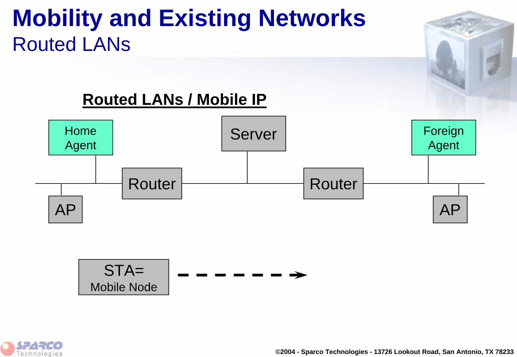
©2004 - Sparco Technologies - 13726 Lookout Road, San Antonio, TX 78233
Mobility and Existing NetworksRouted LANs
Routed LANs / Mobile IP
APRouter
AP
STA=Mobile Node
Router
ServerHomeAgent
ForeignAgent

©2004 - Sparco Technologies - 13726 Lookout Road, San Antonio, TX 78233
Mobility and Existing NetworksRouted LANs
Routed LANs / Mobile IP
APRouter
AP
STA
Router
ServerHomeAgent
ForeignAgent
• Station registers at Foreign Agent• Foreign Agent informs Home Agent• Traffic TO station flows via Home Agent
and Foreign Agent- several “encapsulation” techniques are defined- optimization via “REDIRECT” warning to Correspondent Node (Server)
• Traffic FROM station is routed directly

©2004 - Sparco Technologies - 13726 Lookout Road, San Antonio, TX 78233
Module Contents
• Scan
• Sweep
• Association
• Authentication
• Roaming

©2004 - Sparco Technologies - 13726 Lookout Road, San Antonio, TX 78233
RF Interference

©2004 - Sparco Technologies - 13726 Lookout Road, San Antonio, TX 78233
Module Contents
• The ISM Band
• Sources of interference
• Methods to coexist

©2004 - Sparco Technologies - 13726 Lookout Road, San Antonio, TX 78233
The ISM Band
• Dedicated band made available for radio LANs• Industrial, Scientific and Medical band : 2400 - 2483.5
MHz• Set aside under ETSI (EMEA), FCC (USA), MKK
(Japan)• Each country endorses band (local type approval)• Regulatory body can help out in case of “Illegal users”
FCC MKK
ETSI
26 MHz 83.5 MHz 125 MHz
2.45 GHz915 MHz 5.7875 GHz
World Wide Band

©2004 - Sparco Technologies - 13726 Lookout Road, San Antonio, TX 78233
The ISM Band 2400 - 2483.5 MHz ISM Band Mix
Wireless LANs, WANsall ISM bands @ 100 mWatt
Microwave Ovens & otherIndustrial, Scientific equipment
1 Watt leakage
Government & Militaryradio links

©2004 - Sparco Technologies - 13726 Lookout Road, San Antonio, TX 78233
Module Contents
• The ISM Band
• Sources of interference
• Methods to coexist

©2004 - Sparco Technologies - 13726 Lookout Road, San Antonio, TX 78233
Sources of Interference
• Microwave ovens
• Other wireless systems
• Electrical devices
• Passive systems

©2004 - Sparco Technologies - 13726 Lookout Road, San Antonio, TX 78233
Sources of InterferenceMicrowave oven
M icrow av e Ov en Pow er Leakage
05
101520253035404550
1 8 5 10 7D 11 2 9 13 12 7 6 4Oven Type #
m W
EIRP
Data from NTIA Report 94-303-1 US department of Commerce

©2004 - Sparco Technologies - 13726 Lookout Road, San Antonio, TX 78233
Sources of InterferenceMicrowave Oven - Example of Spectrum Used
100 mW PeakEIRP
ISM Band
Data from NTIA Report 94-303-1 US department of Commerce

©2004 - Sparco Technologies - 13726 Lookout Road, San Antonio, TX 78233
Sources of InterferenceMicrowave Oven - Operational Distances
d2
d1Errorless Performance:
d1=2.1 X d2 Worst Oven
d1= .6 X d2 Average Oven
d1= .35 X d2 Best Case Oven

©2004 - Sparco Technologies - 13726 Lookout Road, San Antonio, TX 78233
Sources of InterferenceTime Domain Emission of Microwave Oven
8.3 ms “off time”
Wireless LANPacketLine Supply Voltage
Data from NTIA Report 94- 303- 1 US department of Commerce
• Microwave oven uses on/off cycle• Off cycle could be used to get wireless
transmissions through• Depending on the power cycle (50 or 60
Hz), the “off time” equals to 10 or 8.3 msec• Transmitting a max size packet (1500
bytes) takes app.:12.5 msec @1 Mbps6.2 msec @2 Mbps2.3 msec @5.5 Mbps1.1 msec @11 Mbps

©2004 - Sparco Technologies - 13726 Lookout Road, San Antonio, TX 78233
Sources of InterferenceMicrowave Oven Robustness
• Under normal operational settings, the Proxim PC Card will fall back in speed after two successive lost ACKs (which can happen as result of interference)
• If the Microwave Oven is the source of the interference, it would mean that the situation gets worse (lower speed means less chance to hit the off-cycle)
• Selecting “Microwave Oven Robustness” avoids falling back in speed too quickly and never drops to 1 Mbps
Example of Proxim PC Card

©2004 - Sparco Technologies - 13726 Lookout Road, San Antonio, TX 78233
Sources of InterferenceOther Wireless Systems
• Other ISM systems– Wireless LANs (FH and DS) typically use low power if adhere to
regulations
• Other (unknown users)– Office buildings with more than company– May need coordination between IT staffs of companies that are interfering
• Non-ISM systems– High powered devices– May need arbitration from regulatory authorities

©2004 - Sparco Technologies - 13726 Lookout Road, San Antonio, TX 78233
Sources of InterferenceElectrical Devices
• Indoor:– Elevator motors– Overhead cranes with heavy spiking electric motors– Welding equipment
• Outdoor elements– Power lines– Electrical railroad track– Power stations

©2004 - Sparco Technologies - 13726 Lookout Road, San Antonio, TX 78233
Sources of InterferencePassive Systems
Passive systems• Indoor
– walls that contain metal – cabinets – metal desks
• Outdoor – Structures, buildings etc– Moving objects: aircraft, cranes, vehicles

©2004 - Sparco Technologies - 13726 Lookout Road, San Antonio, TX 78233
Module Contents
• The ISM Band
• Sources of interference
• Methods to coexist

©2004 - Sparco Technologies - 13726 Lookout Road, San Antonio, TX 78233
Methods to CoexistAccess Point and Station Deployment
• Proper site survey to identify potential sources of interference
• Proper positions of the Radio systems as far away from potential sources of interference
• Deploy additional (redundant systems) Radios
• Advise mobile users to stay clear from sources of interference, when roaming

©2004 - Sparco Technologies - 13726 Lookout Road, San Antonio, TX 78233
Methods to CoexistChannel Choice
• Based on site analysis choose channels away from frequency used by source of interference
• “Tune around source of interference”

©2004 - Sparco Technologies - 13726 Lookout Road, San Antonio, TX 78233
Methods to CoexistEnvironmental Control
• Shield the source of interference
• Change the source of interference (re-tuning to be out of the band)
• Shield the Radio systems to be less effected by source of interference
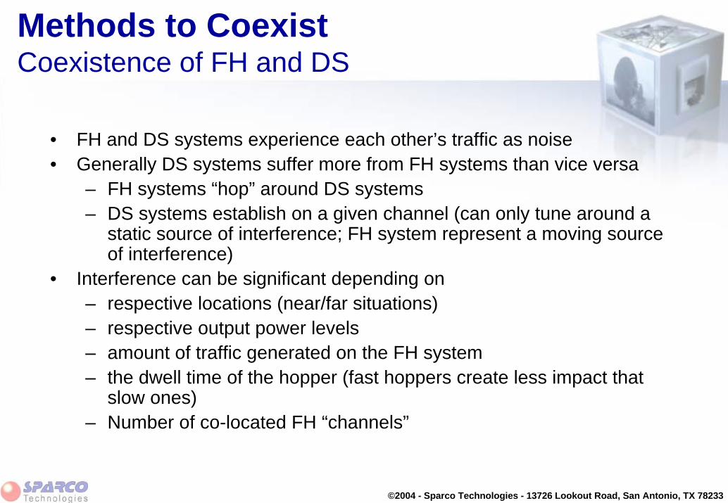
©2004 - Sparco Technologies - 13726 Lookout Road, San Antonio, TX 78233
Methods to Coexist Coexistence of FH and DS
• FH and DS systems experience each other’s traffic as noise• Generally DS systems suffer more from FH systems than vice versa
– FH systems “hop” around DS systems– DS systems establish on a given channel (can only tune around a
static source of interference; FH system represent a moving source of interference)
• Interference can be significant depending on – respective locations (near/far situations)– respective output power levels– amount of traffic generated on the FH system– the dwell time of the hopper (fast hoppers create less impact that
slow ones)– Number of co-located FH “channels”

©2004 - Sparco Technologies - 13726 Lookout Road, San Antonio, TX 78233
Methods to CoexistCoexistence of FH and DS
2.400 2.484
2.400 2.484
2.400 2.484
2.400 2.484
2.400 2.484
2.400 2.484
t1
t2
t3
t4
t5
t6
Co-existence of Radios– Per 1.6 second, 11 noise spikes can be
expected, that may interfere with the channel, based on following parameters:
• dwell time is 20 msec• hop sequence uses 80 frequencies • width of the frequency channel is
11 MHz• there is data traffic between the
stations– Spike is narrow (1 MHz)– Spike lasts for 20 msec

©2004 - Sparco Technologies - 13726 Lookout Road, San Antonio, TX 78233
Methods to CoexistCoexistence of FH and DS - Test Set-up
Notebook
Access Point
BridgeSlave
Station(1)
Station(2)
Hub
BridgeMasterServer
14 meter
3 meter
2 meter
1 meter
Cross-over cable
Test set-up

©2004 - Sparco Technologies - 13726 Lookout Road, San Antonio, TX 78233
Module Summary
• The ISM Band
• Sources of interference
• Methods to coexist