Embed Size (px)
Citation preview

Power and productivity
for a better world™
800xA for TRIO/Genius
System Version 6.0


800xA for TRIO/Genius
System Version 6.0

NOTICEThis document contains information about one or more ABB products and may include a description of or a reference to one or more standards that may be generally relevant to the ABB products. The presence of any such description of a standard or reference to a standard is not a representation that all of the ABB products referenced in this document support all of the features of the described or ref-erenced standard. In order to determine the specific features supported by a particular ABB product, the reader should consult the product specifications for the particular ABB product.
ABB may have one or more patents or pending patent applications protecting the intellectual property in the ABB products described in this document.
The information in this document is subject to change without notice and should not be construed as a commitment by ABB. ABB assumes no responsibility for any errors that may appear in this document.
Products described or referenced in this document are designed to be connected, and to communicate information and data via a secure network. It is the sole responsibility of the system/product owner to provide and continuously ensure a secure connection between the product and the system network and/or any other networks that may be connected.
The system/product owners must establish and maintain appropriate measures, including, but not lim-ited to, the installation of firewalls, application of authentication measures, encryption of data, installa-tion of antivirus programs, and so on, to protect the system, its products and networks, against security breaches, unauthorized access, interference, intrusion, leakage, and/or theft of data or information.
ABB verifies the function of released products and updates. However system/product owners are ulti-mately responsible to ensure that any system update (including but not limited to code changes, con-figuration file changes, third-party software updates or patches, hardware change out, and so on) is compatible with the security measures implemented. The system/product owners must verify that the system and associated products function as expected in the environment they are deployed.
In no event shall ABB be liable for direct, indirect, special, incidental or consequential damages of any nature or kind arising from the use of this document, nor shall ABB be liable for incidental or conse-quential damages arising from use of any software or hardware described in this document.
This document and parts thereof must not be reproduced or copied without written permission from ABB, and the contents thereof must not be imparted to a third party nor used for any unauthorized pur-pose.
The software or hardware described in this document is furnished under a license and may be used, copied, or disclosed only in accordance with the terms of such license. This product meets the require-ments specified in EMC Directive 2004/108/EC and in Low Voltage Directive 2006/95/EC.
TRADEMARKSAll rights to copyrights, registered trademarks, and trademarks reside with their respective owners.
Copyright © 2003-2016 by ABB.All rights reserved.
Release: April 2016Document number: 3BUR002460-600 A

3BUR002460-600 A 5
TABLE OF CONTENTS
About This User ManualGeneral ............................................................................................................................17
Document Conventions ...................................................................................................18
Use of Warning, Caution, Information, and Tip ..............................................................19
Terminology.....................................................................................................................19
Related Documentation ...................................................................................................20
Section 1 - IntroductionOverview..........................................................................................................................21
Installation .......................................................................................................................21
Configuration Tools .........................................................................................................21
Control Builder M ................................................................................................21
Project Explorer ...................................................................................................22
Hand-Held Monitor ..............................................................................................22
Setting Up an HHM to Monitor Units.................................................25
Powering the HHM .............................................................................25
Observing the Block and Circuit LEDs...........................................................................26
Checking Block Power (Unit OK LED is Off or Flickering)...............................27
Checking Communications (I/O Enabled LED is Off or Flickering) ..................27
Checking I/O Circuits: Circuit LEDs...................................................................27
Section 2 - CI862 ConfigurationOverview..........................................................................................................................29
Prepare Project and Hardware .........................................................................................29
Add CI862 Interface.............................................................................................29
Insert Hardware Library .......................................................................................29

Table of Contents
6 3BUR002460-600 A
Load Firmware..................................................................................................... 30
CI862 Redundancy.......................................................................................................... 31
Adding Redundancy............................................................................................. 31
Deleting Backup .................................................................................................. 31
Hardware Editor for CI862 ............................................................................................. 31
Adding New Unit ............................................................................................................ 34
TRIO_Information .......................................................................................................... 36
Section 3 - Editing TRIO/Genius I/OGeneral ............................................................................................................................ 39
Channel Identification.......................................................................................... 39
Channel Name...................................................................................................... 40
Channel Types...................................................................................................... 40
Settings and Common Configurable Features................................................................. 40
Configuration Device........................................................................................... 40
Device Number and Baud Rate............................................................................ 41
Configuration Protection...................................................................................... 41
Automatic Download ........................................................................................... 41
Field Bus Redundancy Features........................................................................... 41
BSM Present (Bus Switching Module)............................................... 41
Output Default Time ........................................................................... 42
BSM Controller................................................................................... 42
Redundancy Mode .............................................................................. 42
Duplex Default State........................................................................... 42
Output Default Values and Failsafe Condition .................................................... 43
Actions upon a Communications Failure............................................ 43
Input Filter Times................................................................................................. 44
Input Filter Time for Analog Units ..................................................... 44
Input Filter Time for Discrete Units ................................................... 44
Pulse Testing for Outputs..................................................................................... 45
Diagnostic Features.............................................................................................. 45
Connections..................................................................................................................... 47
Variable Connections ........................................................................................... 47

Table of Contents
3BUR002460-600 A 7
3BUR002460-600 A 7
I/O Description.....................................................................................................48
Properties .........................................................................................................................49
Status ..............................................................................................................................50
Channel Value and Status.....................................................................................51
Forcing I/O ...........................................................................................................51
Variable Value ......................................................................................................51
Variable .............................................................................................................51
Unit Status .......................................................................................................................52
General System Errors .........................................................................................53
CI862 Device Specific and Extended Status Errors .............................................54
TRIO I/O Device Specific and Extended Status Errors .......................................55
Section 4 - Discrete I/O ConfigurationOverview..........................................................................................................................57
16 Circuit dc Source and Sink I/O (IO_16CKT).............................................................58
Features, 16 Circuit I/O........................................................................................58
Special Configuration Features, 16 Circuit I/O....................................................59
Standard Diagnostics, 16 Circuit I/O ...................................................................60
Overtemperature (Input or Output Diagnostic) ...................................60
Failed Switch (Input or Output Diagnostic)........................................61
Short Circuit (Output Diagnostic) .......................................................61
Optional Diagnostics, 16 Circuit I/O ...................................................................62
Overload (Output Diagnostic).............................................................62
No Load (Output Diagnostic)..............................................................63
Open Wire (No Load) (Tri-state Input Diagnostic).............................63
32 Circuit dc Source and Sink I/O (IO_32CKT).............................................................66
Configurable Features, 32 Circuit I/O..................................................................66
Special Configuration Features, 32 Circuit I/O....................................................67
Standard Diagnostics, 32 Circuit I/O ...................................................................67
Short Circuit (protection against excessive current) ...........................68
Surge Current ......................................................................................68
Overcurrent (protection against excessive load) .................................68
115 V ac 8 Circuit Grouped and Low Leakage I/O (GRP_8CKT) .................................69

Table of Contents
8 3BUR002460-600 A
Configurable Features, 8 Circuit Grouped I/O .................................................... 69
Special Configuration Features, 8 Circuit Grouped I/O ...................................... 71
Standard Diagnostics, 8 Circuit Grouped I/O...................................................... 72
Overtemperature (Input or Output Diagnostic)................................... 72
Failed Switch (Input or Output Diagnostic)........................................ 72
Short Circuit (Output Diagnostic)....................................................... 72
Optional Diagnostics, 8 Circuit Grouped I/O ...................................................... 73
Overload (Output Diagnostic)............................................................. 73
Open Wire ...................................................................................... 74
No Load ...................................................................................... 75
115 V ac/125 V dc Isolated I/O (ISO_8CKT)................................................................. 76
Configurable Features, 8 Circuit Isolated ............................................................ 76
Special Configuration Features, 8 Circuit Isolated .............................................. 78
Standard Diagnostics, 8 Circuit Isolated.............................................................. 79
Overtemperature (Input or Output Diagnostic)................................... 79
Failed Switch (Input or Output Diagnostic)........................................ 80
Short Circuit (Output Diagnostic)....................................................... 80
Optional Diagnostics, 8 Circuit Isolated.............................................................. 82
Overload (Output Diagnostic)............................................................. 83
Loss of I/O Power ............................................................................... 83
Open Wire ...................................................................................... 84
No-Load ...................................................................................... 84
115 V ac 16 Circuit Input (IN_16CKT) .......................................................................... 86
Configurable Features, 16 Circuit Input .............................................................. 86
Special Configuration Features, 16 Circuit Input ................................................ 87
Optional Diagnostics, 16 Circuit Input ................................................................ 88
Open Detect ...................................................................................... 88
Short Detect ...................................................................................... 89
Optional Open Detect and Short Detect Diagnostics.......................... 90
Using Open and Short Circuit Diagnostics Together.......................... 90
Selecting Thresholds and Resistor Values .......................................... 91
Selecting Thresholds........................................................................... 91

Table of Contents
3BUR002460-600 A 9
3BUR002460-600 A 9
Selecting Resistor Values ....................................................................93
Calculating Resistor Values when V% is Known ...............................94
Relay Output (OP_16CKT) .............................................................................................95
Configurable Features, 16 Circuit Relay Output..................................................95
Special Configuration Features, 16 Circuit Relay Output....................................96
Standard Diagnostics, 16 Circuit Relay Output ...................................................96
Section 5 - Analog I/O ConfigurationOverview..........................................................................................................................97
4 In/2 Out Analog Input/Output (4IN2OUT) ..................................................................97
Configurable Features, 4 In/2 Out Analog Input/Output .....................................98
Special Configuration Features, 4 In/2 Out Analog I/O.....................................100
Current/Voltage Range ......................................................................101
Scaling Parameters ............................................................................102
Tips for Scaling an Input for a Loop .................................................103
Input Filter Time for the Channel .....................................................104
Report Faults ....................................................................................105
Alarm Input Mode and Low/High Alarms........................................107
4 In/2 Out Analog I/O Diagnostics ....................................................................107
Open Wire ....................................................................................107
Underrange and Overrange ...............................................................107
Input Overrange.................................................................................107
Input Underrange ..............................................................................107
Output Overrange and Underrange ...................................................108
Configuration Examples for the 4 In/2 Out Analog I/O.....................................109
Example 1: Acquiring an Analog Value............................................109
Example 2: Acquiring a Flow Value with Square Root Extraction Performed in the Controller........................................110
Example 3: Sending a 0 to 10 V Output to the Field ........................111
4 In/2 Out Current Source Analog I/O (CSANALOG) .................................................112
Configurable Features, 4 In/2 Out Current Source Analog Input/Output ..........112
Special Configuration Features, 4 In/2 Out Current Source Analog I/O ...........114
Input Filter Time ...............................................................................115

Table of Contents
10 3BUR002460-600 A
Input Channels .................................................................................. 116
Input Channel Scaling Parameters .................................................... 116
Active Input Channel ........................................................................ 117
Report Faults .................................................................................... 118
Square Root Extraction ..................................................................... 119
Output Channel Configuration Fields............................................... 119
Output Channel Scaling Parameters ................................................. 119
Active Output Channels .................................................................... 120
Settle Time for Output Channels ...................................................... 121
Output Feedback Enable ................................................................... 121
4 In/2 Out Current Source Analog I/O Diagnostics........................................... 121
Open Wire .................................................................................... 121
Underrange and Overrange ............................................................... 122
Input Overrange ................................................................................ 122
Input Underrange .............................................................................. 122
Output Overrange and Underrange................................................... 122
Feedback Error.................................................................................. 122
Configuration Examples for the 4 In/2 Out Current Source Analog I/O........... 123
Example 1: Acquiring an Analog Value ........................................... 123
Example 2: Acquiring a Flow Value with Square Root Extraction Performed in the Controller ....................................... 124
Example 3: Sending a 4 to 20 mA Output to the Field..................... 125
6 Circuit Current Source Analog Input (CSANAINP).................................................. 127
Configurable Features, 6 Circuit Current Source Analog Input ........................ 127
Special Configuration Features, 6 Circuit Current Source Analog Input .......... 128
Input Filter Time ............................................................................... 129
Input Channels .................................................................................. 130
Input Channel Scaling Parameters .................................................... 130
Active Input Channel ........................................................................ 132
Report Faults .................................................................................... 132
6 Circuit Current Source Analog Input Diagnostics .......................................... 133
Open Wire .................................................................................... 133

Table of Contents
3BUR002460-600 A 11
3BUR002460-600 A 11
Underrange and Overrange ...............................................................133
Input Overrange.................................................................................133
Input Underrange ..............................................................................133
Configuration Examples for the 6 Circuit Current Source Analog Input ..........134
Example 1: Acquiring an Analog Value............................................134
Example 2: Acquiring a Flow Value with Square Root Extraction Performed in the Controller........................................135
6 Circuit Current Source Analog Output (CSANAOUT)..............................................137
Configurable Features, 6 Circuit Current Source Analog Output ......................137
Special Configuration Features, 6 Circuit Current Source Analog Output........138
Output Channel Scaling Parameters..................................................139
Active Output Channels ....................................................................141
Settle Time for Output Channels.......................................................141
Output Feedback Enable ...................................................................141
6 Circuit Current Source Analog Output Diagnostics........................................142
Output Overrange and Underrange ...................................................142
Feedback Error ..................................................................................142
Configuration Examples for the 6 Circuit Current Source Analog Output........142
Example 3: Sending a 4 to 20 mA Output to the Field .....................142
6 Circuit Thermocouple Input (TC) ..............................................................................144
Configurable Features, 6 Circuit Thermocouple Input ......................................144
Special Configuration Features, 6 Circuit Thermocouple Input ........................145
Engineering Units..............................................................................146
Thermocouple Type for the Channel.................................................147
Channel Compensation .....................................................................147
User-defined Compensation Value for the Channel ..........................147
Field Offset for the Channel..............................................................148
Report Faults for the Channel ...........................................................148
Active Input Channel.........................................................................148
6 Circuit Thermocouple Input Diagnostics ........................................................148
Input Underrange ..............................................................................148
Input Overrange.................................................................................148

Table of Contents
12 3BUR002460-600 A
Input Open Wire................................................................................ 149
Internal Channel Fault....................................................................... 149
Configuration Examples for the 6 Circuit Thermocouple Input ........................ 149
Temperature Input via a Thermocouple............................................ 149
Millivolt Input when Thermocouple Block has Eng Units of MV ...150
Millivolt Input when Thermocouple Block has Eng Units of DEGC151
6 Circuit RTD Input (RTD) ........................................................................................... 153
Configurable Features, 6 Circuit RTD Input...................................................... 153
Special Configuration Features, 6 Circuit RTD Input ....................................... 154
Input Filter Time ............................................................................... 154
Engineering Units ............................................................................. 154
Linearization .................................................................................... 154
RTD Resistance................................................................................. 156
Alpha Value .................................................................................... 156
Report Faults .................................................................................... 156
Activate Input.................................................................................... 156
6 Circuit RTD Input Diagnostics ....................................................................... 157
Input Shorted .................................................................................... 157
Internal Fault .................................................................................... 157
Wiring Error .................................................................................... 157
Open Wire .................................................................................... 157
Overrange .................................................................................... 157
Underrange .................................................................................... 158
Configuration Example for the 6 Circuit RTD Input ......................................... 158
Section 6 - High Speed Counter ConfigurationOverview ....................................................................................................................... 161
Configurable Features, High Speed Counter ..................................................... 161
Special Configuration Features, High Speed Counter ....................................... 164
BLOCK NUMBER........................................................................... 164
Automatic Download ........................................................................ 165
Control Input Threshold.................................................................... 165
Counter Input Threshold................................................................... 165
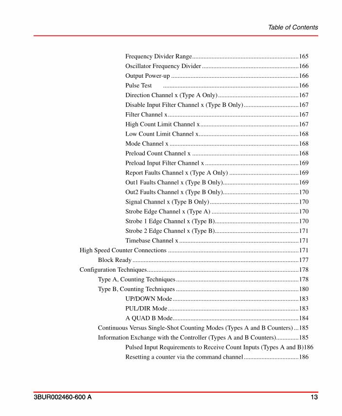
Table of Contents
3BUR002460-600 A 13
3BUR002460-600 A 13
Frequency Divider Range..................................................................165
Oscillator Frequency Divider ............................................................166
Output Power-up ...............................................................................166
Pulse Test ....................................................................................166
Direction Channel x (Type A Only) ..................................................167
Disable Input Filter Channel x (Type B Only)..................................167
Filter Channel x.................................................................................167
High Count Limit Channel x.............................................................167
Low Count Limit Channel x..............................................................168
Mode Channel x ................................................................................168
Preload Count Channel x ..................................................................168
Preload Input Filter Channel x ..........................................................169
Report Faults Channel x (Type A Only) ...........................................169
Out1 Faults Channel x (Type B Only)...............................................169
Out2 Faults Channel x (Type B Only)...............................................170
Signal Channel x (Type B Only) .......................................................170
Strobe Edge Channel x (Type A) ......................................................170
Strobe 1 Edge Channel x (Type B)....................................................170
Strobe 2 Edge Channel x (Type B)....................................................171
Timebase Channel x ..........................................................................171
High Speed Counter Connections .................................................................................171
Block Ready .......................................................................................................177
Configuration Techniques..............................................................................................178
Type A, Counting Techniques ............................................................................178
Type B, Counting Techniques ............................................................................180
UP/DOWN Mode..............................................................................183
PUL/DIR Mode.................................................................................183
A QUAD B Mode..............................................................................184
Continuous Versus Single-Shot Counting Modes (Types A and B Counters) ...185
Information Exchange with the Controller (Types A and B Counters)..............185
Pulsed Input Requirements to Receive Count Inputs (Types A and B)186
Resetting a counter via the command channel ..................................186

Table of Contents
14 3BUR002460-600 A
Strobe Inputs (Types A and B Counters) .......................................... 186
Strobe Status and Reset Signals........................................................ 189
Before the Strobe Fires ..................................................................... 189
After the Strobe Fires........................................................................ 189
Preload Control Signal (Types A and B Counters) ............................................ 190
Preload Status and Reset Signals ...................................................... 192
Before the Preload Fires ................................................................... 192
After the Preload Fires ...................................................................... 192
Disable Counting Signal (Type B Counter) ....................................................... 193
Outputs (Types A and B Counters) .................................................................... 194
Output Presets ................................................................................... 194
Using Digital Input and Output with the Output/Preset Feature ...... 197
Short Circuit Protection for Outputs ................................................. 199
Appendix A - DiagnosticsIntroduction ................................................................................................................... 201
Genius Remote I/O (TRIO) Diagnostics....................................................................... 201
BLOCKS HAVE SWITCHED TO LAN B, CHECK LAN A.......... 201
BLOCKS HAVE SWITCHED TO LAN A, CHECK LAN B.......... 201
CHECK TRL CONNECTION ......................................................... 202
BLOCK %d TERMINAL STRIP EEPROM FAILED ..................... 202
BLOCK %d ELECTRONICS ASSEMBLY EEPROM FAILED..... 202
BLOCK %d SHARED RAM FAILED - REPLACE BLOCK ......... 203
BLOCK %d INTERNAL CIRCUIT FAILED.................................. 203
BLOCK %d CHANNEL %d LOST I/O POWER............................ 203
BLOCK %d CHANNEL %d HAS SHORT CIRCUIT .................... 203
BLOCK %d CHANNEL %d OUTPUT CIRCUIT OVERLOAD.... 203
BLOCK %d CHANNEL %d HAS NO LOAD ON OUTPUT......... 204
BLOCK %d CHANNEL %d INPUT CIRCUIT OPEN................... 204
BLOCK %d CHANNEL %d CIRCUIT OVER 100 DEGC............. 204
BLOCK %d CHANNEL %d UNKNOWN CIRCUIT FAILURE.... 204
BLOCK %d CHANNEL %d INPUT UNDERRANGE................... 204
BLOCK %d CHANNEL %d INPUT OVERRANGE...................... 205
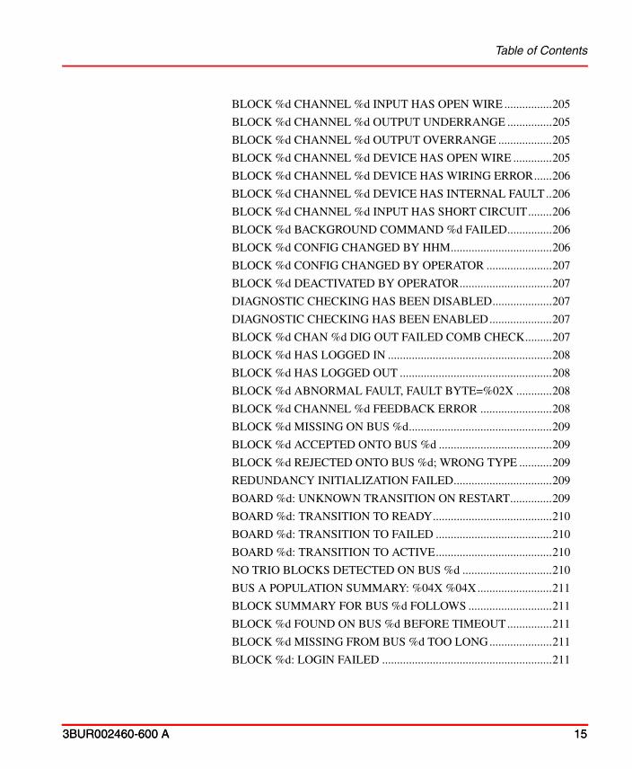
Table of Contents
3BUR002460-600 A 15
3BUR002460-600 A 15
BLOCK %d CHANNEL %d INPUT HAS OPEN WIRE ................205
BLOCK %d CHANNEL %d OUTPUT UNDERRANGE ...............205
BLOCK %d CHANNEL %d OUTPUT OVERRANGE ..................205
BLOCK %d CHANNEL %d DEVICE HAS OPEN WIRE .............205
BLOCK %d CHANNEL %d DEVICE HAS WIRING ERROR......206
BLOCK %d CHANNEL %d DEVICE HAS INTERNAL FAULT..206
BLOCK %d CHANNEL %d INPUT HAS SHORT CIRCUIT........206
BLOCK %d BACKGROUND COMMAND %d FAILED...............206
BLOCK %d CONFIG CHANGED BY HHM..................................206
BLOCK %d CONFIG CHANGED BY OPERATOR ......................207
BLOCK %d DEACTIVATED BY OPERATOR...............................207
DIAGNOSTIC CHECKING HAS BEEN DISABLED....................207
DIAGNOSTIC CHECKING HAS BEEN ENABLED.....................207
BLOCK %d CHAN %d DIG OUT FAILED COMB CHECK.........207
BLOCK %d HAS LOGGED IN .......................................................208
BLOCK %d HAS LOGGED OUT ...................................................208
BLOCK %d ABNORMAL FAULT, FAULT BYTE=%02X ............208
BLOCK %d CHANNEL %d FEEDBACK ERROR ........................208
BLOCK %d MISSING ON BUS %d................................................209
BLOCK %d ACCEPTED ONTO BUS %d ......................................209
BLOCK %d REJECTED ONTO BUS %d; WRONG TYPE ...........209
REDUNDANCY INITIALIZATION FAILED.................................209
BOARD %d: UNKNOWN TRANSITION ON RESTART..............209
BOARD %d: TRANSITION TO READY........................................210
BOARD %d: TRANSITION TO FAILED .......................................210
BOARD %d: TRANSITION TO ACTIVE.......................................210
NO TRIO BLOCKS DETECTED ON BUS %d ..............................210
BUS A POPULATION SUMMARY: %04X %04X.........................211
BLOCK SUMMARY FOR BUS %d FOLLOWS ............................211
BLOCK %d FOUND ON BUS %d BEFORE TIMEOUT...............211
BLOCK %d MISSING FROM BUS %d TOO LONG.....................211
BLOCK %d: LOGIN FAILED .........................................................211

Table of Contents
16 3BUR002460-600 A
UNEXPECTED MSG RECEIVED FROM TRIO BLOCK %d ...... 212
BLOCK %d: USER REQUEST % RECEIVED .............................. 212
ADDRESS OF GENI %d NOT SET TO 31..................................... 212
OUTPUTS OF GENI %d ARE NOT DISABLED........................... 213
I/O TABLE LENGTH OF GENI %d IS NOT 128 ........................... 213
FAULTS DETECTED ON GENI %d............................................... 213
WATCHDOG EXPIRED ON GENI %d........................................... 213
EXCESSIVE BUS ERRORS ON GENI %d .................................... 213
CONFIG DOWNLOAD SKIPPED FOR BLOCK %d .................... 214
ERROR DOWNLOADING CONFIG TO BLOCK %d................... 214
CTLR WATCHDOG EXPIRED....................................................... 214
FORCING GENI TO FAILED STATE, REASON %d .................... 215
SELF WATCHDOG EXPIRED........................................................ 215
SELF WATCHDOG COULD NOT START..................................... 215
Appendix B - TRIO Command AspectIntroduction ................................................................................................................... 217
Using the TRIO Command Aspect ............................................................................... 217
TRIO/Genius Commands.............................................................................................. 218
INDEX

3BUR002460-600 A 17
About This User Manual
General
Taylor™ Remote I/O (TRIO) is a Genius I/O product that includes a variety of multi-channel analog and discrete I/O as well as high speed counters. These TRIO I/O blocks (units) are connected to the 800xA System through Field Buses and the CI862 TRIO/Genius Interface module. This user manual covers procedures for:
• Configuring the CI862 TRIO/Genius Interface.
• Configuring TRIO/Genius modules.
• Hand Held Monitor usage.
This user manual is for engineers who configure controller and I/O hardware. Users should understand distributed automated process control and the 800xA System. See Related Documentation on page 20.
Any security measures described in this User Manual, for example, for user access, password security, network security, firewalls, virus protection, etc., represent possible steps that a user of an 800xA System may want to consider based on a risk assessment for a particular application and installation. This risk assessment, as well as the proper implementation, configuration, installation, operation, administration, and maintenance of all relevant security related equipment, software, and procedures, are the responsibility of the user of the 800xA System.

Document Conventions About This User Manual
18 3BUR002460-600 A
Document ConventionsMicrosoft Windows conventions are normally used for the standard presentation of material when entering text, key sequences, prompts, messages, menu items, screen elements, etc.

About This User Manual Document Conventions
3BUR002460-600 A 19
Use of Warning, Caution, Information, and Tip
Electrical warning icon indicates the presence of a hazard which could result in electrical shock.
Warning icon indicates the presence of a hazard which could result in personal injury.
Caution icon indicates important information or warning related to the concept discussed in the text. It might indicate the presence of a hazard which could result in corruption of software or damage to equipment/property.
Information icon alerts the reader to pertinent facts and conditions.
Tip icon indicates advice on, for example, how to design your project or how to use a certain function.
This publication includes Warning, Caution, and Information where appropriate to point out safety related or other important information. It also includes Tip to point out useful hints to the reader. The corresponding symbols should be interpreted as follows:
Although Warning hazards are related to personal injury, and Caution hazards are associated with equipment or property damage, it should be understood that operation of damaged equipment could, under certain operational conditions, result in degraded process performance leading to personal injury or death. Therefore, comply fully with all Warning and Caution notices.
TerminologyA complete and comprehensive list of Terms is included in the System 800xA System Guide, Functional Description (3BSE038018*). The listing includes terms and definitions as they apply to the 800xA system where the usage is different from commonly accepted industry standard definitions and definitions given in standard dictionaries such as Webster’s Dictionary of Computer Terms.

Term Description
BSM Bus Switch Module
CEM Communication Expansion Module
CEX-Bus Communication Expansion Bus
HDW Hardware Definition files describe the hardware and its characteristics to the system. Once the TRIO HDW files are incorporated into the Control Builder, users can add TRIO elements into their hardware tree structure.
HHM Hand Held Monitor
HSC High Speed Counter
TRIO Taylor Remote I/O or Genius I/O
TRL TRIO Redundant Link
Document Conventions About This User Manual
20 3BUR002460-600 A
You should also be familiar with the following list of terms used in this instruction:
Related DocumentationA complete list of all documents applicable to the 800xA System is provided in Released User Documents, 3BUA000263*. This document lists applicable Release Notes and User Instructions. It is provided in PDF format and is included on the Release Notes/Documentation media provided with your system. Released User Documents are updated with each release and a new file is provided that contains all user documents applicable for that release with their applicable document number. Whenever a reference to a specific instruction is made, the instruction number is included in the reference.

3BUR002460-600 A 21
Section 1 Introduction
OverviewThe CI862 TRIO/Genius Interface provides device integration of the TRIO/Genius remote I/O product (TRIO) to the AC800M Controller. The definition of the hardware and the connection of the I/O is performed in the Controllers folder of the Control Builder M as described in this user manual. The Control Builder uses an ABB implementation of the IEC 61131 standard for application configuration. These products are part of the Industrial IT 800xA System.
InstallationThe TRIO components i.e., the TRIO hardware library(CI862TRIOHwlib) and the TRIO command aspect shall be added into the system when the AC 800M Connect extension are loaded.
Configuration ToolsThe Control Builder is an engineering tool for the AC800M controller. Each TRIO unit is supplied with default configuration options which can be changed to suit the application. Other than baud rate and block number, no parameters are set using the Hand-Held Monitor.
Control Builder M
Control Builder M is used to configure the CI862 TRIO/Genius Interface and the TRIO units. A Project Explorer tree is used to represent the hardware units. A hardware editor is used to edit the settings for a unit and associate variables to I/O channels.

Project Explorer Section 1 Introduction
22 3BUR002460-600 A
The Control Builder contains a set of hardware definition files to edit (configure) the databases of the units. The editor is used to specify the basic parameters for the units and determine the startup characteristics of the system. Startup items include:
• Database is automatically downloaded to the units upon startup.
• Resume communication with a TRIO unit, or wait for loop download.
• Coldstart - if calculated output values are sent at startup.
Project Explorer
Objects in the Project Explorer are displayed in a tree view control. TRIO is an I/O product that is configured as part of the Controllers folder. Each Controller can have up to four CI862 TRIO/Genius Interface modules. Up to 30 remote I/O units can be connected to the CI862. The maximum I/O with TRIO in an AC800M is 1000 IO points. For a unit to be available for insertion into the hardware tree, there must be a hardware definition file that describes the unit.
Hand-Held Monitor
The Hand-held Monitor (HHM), Figure 1, is a portable interface device used to monitor the operation of TRIO units and the Field Bus. The HHM plugs directly into any unit, Field Bus Interface Module, CI862 TRIO/Genius Interface module, or connector on the bus. You can permanently mount the HHM to create an operator workstation. A mounting kit is provided with each HHM for this purpose. A
The CI862 can be used in a redundant processor module configuration under the following conditions:
a. If the CI862 is used with redundant PM866, only the TK850 CEX-bus extension cable shall be used for interconnection between the PM866 modules. The BC810 shall not be used.
b. If the CI862 is used with other redundant processor modules (PM861A/PM864A/PM865), either BC810 or TK850 CEX-bus extension cable can be used for interconnection between the two processor modules.
The CI862 is not supported with the PM891 processor module.

Do not attempt to configure a TRIO unit with the Hand-held Monitor. Leave the HHM in the monitor mode and do not override the configuration lock. All configuration data must come from the configurator. The only exception is the baud rate and block number which are set before placing the block on the LAN.
Section 1 Introduction Hand-Held Monitor
3BUR002460-600 A 23
keyswitch allows you to set up the HHM for a wide range of applications. Leave the keyswitch in the monitor position.
The Control Builder does not support the upload of a database configured with the Hand-held Monitor (HHM). The block number and baud rate are matched to the configuration with Control Builder M. No other setup activities are performed with the HHM.
Upon unit initialization (when it logs in), the system automatically forces all units to the Configuration Protected mode. The ability to change the unit configuration with the HHM is protected. An HHM user would have to switch the unit from Monitor to Configure and change the unit configuration mode from protected to unprotected.

Figure 1. Hand-Held Monitor
Hand-Held Monitor Section 1 Introduction
24 3BUR002460-600 A
mon
cfg
TAYLORMOD SYSTEMS
F1 F2 F3 F4
7 8 9 Home
4 5 6
1 2 3 Clear
0 . On
Menu
Off
Mode Select
LCD Display
Function Keys
Decimal Keys
Operation Keys
Connection forCharger/Adaptor
Keyswitch

Section 1 Introduction Hand-Held Monitor
3BUR002460-600 A 25
Setting Up an HHM to Monitor Units
Table 1. HHM Parameters and Settings
Parameter Setting Description
Baud rate: 153.6K Standard The baud rate of the HHM must match the baud rate of the unit. If you plan to configure units that have been changed to 153.6K extended, you must change the HHM to 153.6K extended.
Device number:
0 The default device number, 0, should be kept.
Host CPU: Series 90/PCIM (HHM at revision level 3.7 or below)
PCIM/QBIM/GENI (HHM at revision level 3.8 or above)
An entry that prevents the HHM from displaying a number of configuration screens that are not applicable to TRIO.
A new HHM comes with a standard configuration that you can change from its keypad. The following procedures describe how to configure the HHM so you can use it to monitor TRIO units. Table 1 lists the HHM configuration settings that are needed.
Powering the HHM
You can operate the HHM with either ac power or its internal battery pack. When you receive a new HHM, its battery pack is not charged. You can use the HHM immediately by plugging it into appropriate AC power (first, set the power selection switch on the adapter to match the incoming AC power). Before you can operate the HHM on battery power, you must charge the battery pack. For a new HHM (or a new battery pack) the time required for the first charging is 24 hours. Subsequent charging takes 16 hours. The charger/adapter performs one function at a time; the battery does not charge while the HHM is operating on ac power.

Observing the Block and Circuit LEDs Section 1 Introduction
26 3BUR002460-600 A
Observing the Block and Circuit LEDs
Figure 2. Block LEDs
When power is wired to the block and the block is properly grounded, you can check for proper operation by observing the LEDs on the front of the block, Figure 2.
Unit OK LED
I/O Enabled LED
• Blinks for circuitdiagnostic fault
Off for not blockpower
•
• On when CPU iscommunicating
Blinks if any circuitis forced
•
with block
Circuit LEDs
• Show I/O statesfor discreteblocks

Section 1 Introduction Checking Block Power (Unit OK LED is Off or Flickering)
3BUR002460-600 A 27
Checking Block Power (Unit OK LED is Off or Flickering)
If power is applied to a block, the Unit OK LED of the block should be on. If the Unit OK LED is not on, either the block is not receiving power or the block is faulty.
Check block power and wiring. If the Unit OK LED is blinking at a regular rate but not synchronously with the I/O Enabled LED, a circuit or EEPROM fault exists on the block.
In addition, the following problems may occur for the 6 Circuit RTD Input Block:
• The Program Block ID screen of the HHM does not display the block or reference numbers even if they were previously assigned.
• The block is skipped on the Block/Bus Status screen.
• The block may experience difficulty communicating with the CPU.
For any of the above scenario, replace the Terminal Assembly of the 6233B 6 Circuit RTD Input Block. Refer to 800xA TRIO/Genius Getting Started (3BUR002459*).
Checking Communications (I/O Enabled LED is Off or Flickering)
If the block is connected to an operating bus, the I/O Enabled LED is on if the block is receiving uninterrupted communications from the CI862 interface module. If the bus is connected to an operating CI862 but the I/O Enabled LED is off, the block has not received any communications for 3 bus scans. Check the serial bus wiring and the settings of the LEDs on the CI862 interface module.
If the Unit OK and I/O Enabled LEDs are blinking together, the block has been assigned a device number already in use. Use the HHM to change the device number to an unused number. Change the Block Templet for the block to reflect the changed device number.
Checking I/O Circuits: Circuit LEDs
Circuit LEDs provide information about individual inputs and outputs. If the I/O Enabled LED is blinking, it means one of the circuits on the block is forced.

Checking I/O Circuits: Circuit LEDs Section 1 Introduction
28 3BUR002460-600 A
3BUR002460-600 A 29
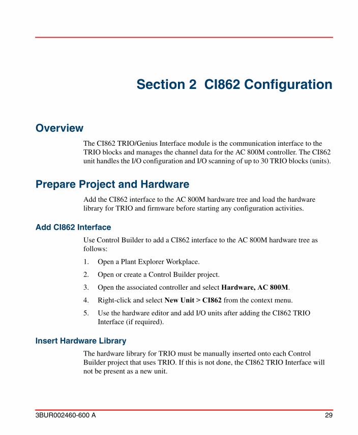
Section 2 CI862 Configuration
OverviewThe CI862 TRIO/Genius Interface module is the communication interface to the TRIO blocks and manages the channel data for the AC 800M controller. The CI862 unit handles the I/O configuration and I/O scanning of up to 30 TRIO blocks (units).
Prepare Project and HardwareAdd the CI862 interface to the AC 800M hardware tree and load the hardware library for TRIO and firmware before starting any configuration activities.
Add CI862 Interface
Use Control Builder to add a CI862 interface to the AC 800M hardware tree as follows:
1. Open a Plant Explorer Workplace.
2. Open or create a Control Builder project.
3. Open the associated controller and select Hardware, AC 800M.
4. Right-click and select New Unit > CI862 from the context menu.
5. Use the hardware editor and add I/O units after adding the CI862 TRIO Interface (if required).
Insert Hardware Library
The hardware library for TRIO must be manually inserted onto each Control Builder project that uses TRIO. If this is not done, the CI862 TRIO Interface will not be present as a new unit.

Load Firmware Section 2 CI862 Configuration
30 3BUR002460-600 A
Use Control Builder to install the hardware library for TRIO as follows:
1. Open a Plant Explorer Workplace.
2. Open or create a Control Builder project.
3. Select Library > Hardware.
4. Right-click Hardware and select the TrioHwLib library from the context menu.
5. Click Insert.
6. Select OK to insert the hardware definition files. Control Builder will read the files and then restart automatically.
Control Builder can now be used to configure TRIO/Genius I/O.
Load Firmware
Use Control Builder to ensure that the latest firmware is installed on the controller and the CI862 TRIO Interface as follows:
1. Open a Plant Explorer Workplace.
2. Open or create a Control Builder project.
3. Select Tools > Maintenance > Remote System.
4. Click Show Remote Systems.
5. Select the remote system IP address for the selected controller and click OK.
6. Click Show Firmware Information. The dialog will show the current version and what is available on disk.
7. Enable the download check box for the new version of hardware.
8. Click Download Firmware for selected Units and click Continue when prompted.
9. Click OK.

Section 2 CI862 Configuration CI862 Redundancy
3BUR002460-600 A 31
CI862 RedundancyRedundant CI862 interface modules appear to Control Builder M and the AC 800M Controller to be redundant in their usual primary and backup sense. However, when operational, both of the boards are active and running at the same time and are actively controlling their respective bus. They are more accurately called primary and secondary. The primary module maintains an image of the channel data for itself and for the secondary (backup) module. This single image allows both modules to be active at the same time allowing I/O blocks to communicate to either CI862 interface module. The AC 800M writes outputs to both CI862 interface modules and reads inputs from the designated primary.
Adding Redundancy
Redundancy is specified for an existing CI862 interface module by selecting the module and using the context menu to select Redundancy > Add Redundant Unit. In the Choose Position for backup dialog, select the address of the redundant unit.
The second CI862 unit is indicated as shown for position 1 and 2.
A change in redundancy configuration. causes a major controller change.
Deleting Backup
Redundancy is removed for an existing CI862 redundant pair by selecting the CI862 and using the context menu to select Redundancy > Delete Backup.
Hardware Editor for CI862The following default values may be used as guidelines for setting parameters:

Table 2. CI862 Settings
Parameter Type Default Value Description
Baud Rate enum 153.6 ext 153.6 ext38.476.8153.6 std
Baud Rate (kb)
Diagnostics Enabled
bool False True (enabled), False (disabled)
Enable diagnostics
Figure 3. CI862 Settings
Hardware Editor for CI862 Section 2 CI862 Configuration
32 3BUR002460-600 A
Unit Status is the only connection available under the Connections tab for the CI862. Application variables are connected to this by entering the variable path in the Variable column. Use the syntax POUname.variable.

Table 3. CI862 Connections
Connections Description
Unit Status The data type for the variable, which you can connect to the Unit Status I/O channel of a hardware unit. The variable can be of the simple data type dint or of the complex data type HwStatus. If it is of dint type it holds the HwState component of the HwStatus data type. Components of HwStatus are HwState, HWStateChangeTime, ErrorsAndWarnings and LatchedErrorsAndWarnings.
Section 2 CI862 Configuration Hardware Editor for CI862
3BUR002460-600 A 33
The Unit Status tab shows the current and latched status of the unit while in the online mode. Both general system errors and device-specific errors are shown. See Unit Status on page 52.

Adding New Unit Section 2 CI862 Configuration
34 3BUR002460-600 A
Adding New UnitPerform the following to add TRIO units to the CI862:
1. Select the CI862 and then use the context menu to select Insert Unit, Figure 4.
Figure 4. Adding New Unit

Section 2 CI862 Configuration Adding New Unit
3BUR002460-600 A 35
2. Select the unit type to be added as described below. Supported I/O are:
I/O Unit Description
4IN2OUT Analog, 4 input 2 Output
CSANALOG Analog, Current Source Analog I/O, 4 input 2 Output
TC Analog, Thermocouple, 6 input
RTD Analog, RTD, 6 input
CSANAINP Analog, Current Source Analog Input, 6 input
CSANAOUT Analog, Current Source Analog Output, 6 input
IO_16CKT Digital, 16 Circuit I/O, configurable input or output
IO_32CKT Digital, 32 Circuit I/O, configurable input or output
GRP_8CKT Digital, 8 Circuit Grouped, configurable input or output
ISO_8CKT Digital, 8 Circuit Isolated, configurable input or output
IN_16CKT Digital, 16 Circuit Input
OP_16CKT Digital, 16 Circuit Output
HSC_A Counter, High Speed Counter A, 4 - 16 bit Up/Down Counters
HSC_B Counter, High Speed Counter B, 2 Bi-directional 24 bit Up/Down Counters
3. Choose the position for the unit (Block Number). Choices are 1 to 30 depending on the positions available. The position assigned here must match the block number given to the TRIO block by the HHM.
The unit appears in the tree structure for the CI862 and can be edited as described in the following sections.
4. Select TRIO_INFORMATION from the bottom of the list and add it as Unit 31. This is a CI862 status block as described in the following subsection.

TRIO_Information Section 2 CI862 Configuration
36 3BUR002460-600 A
TRIO_Information
Figure 5. TRIO_INORMATION Status
The TRIO Information unit provides a command channel, CPU load and a field bus scan time for the CI862 module. Use the Connections tab to make connections to the functions described below.
Command Channel Commands issued to this channel, such as Clear Faults, are sent to all blocks on the field bus.
Current CPU Load Current level of load on the CI862 module.
Average CPU Load Average level of load on the CI862 module.
Minimum CPU Load Minimum level of load on the CI862 module.
Maximum CPU Load Maximum level of load on the CI862 module.
Bus Scan Time On the Field Bus side, information is written at the Field Bus scan rate whose period is determined by the baud rate and number of devices on the bus. The Field Bus scan rate is usually in the order of 20 mSec.
See 800xA TRIO/Genius, Getting Started (3BUR002459*) for calculations and scan times for devices on the field bus.

Section 2 CI862 Configuration TRIO_Information
3BUR002460-600 A 37
The Status tab is active in online mode only. The Status tab contains the Channel Value, Forced, Variable Value, and Variable as described in Status on page 50.
The Unit Status tab shows the current and latched status of the unit while in the online mode. Both general system errors and device-specific errors are shown. See Unit Status on page 52.
Unit Status The data type for the variable, which you can connect to the Unit Status I/O channel of a hardware unit. The variable can be of the simple data type dint or of the complex data type HwStatus. If it is of dint type it holds the HwState component of the HwStatus data type. Components of HwStatus are HwState, HWStateChangeTime, ErrorsAndWarnings and LatchedErrorsAndWarnings.

TRIO_Information Section 2 CI862 Configuration
38 3BUR002460-600 A

3BUR002460-600 A 39
Section 3 Editing TRIO/Genius I/O
GeneralThe Hardware Editor in the Control Builder is used to make configuration settings for the I/O modules and channels, connections to applications, view channel properties and status as well as the status of the I/O module unit (block).
Channel Identification
The address of an I/O channel is made up of a channel type prefix, the address of the CI862, the I/O unit position, and the channel address.
• A prefix indicates the type of channel:
– IX = in Booleans.
– QX = out Booleans.
– IW = in non-Booleans.
– QW = out non-Booleans.
• The hardware address is determined by its position in the Control Builder hardware tree. The first part is the position of the CI862 on the CEX bus of an AC 800M controller, a dot (.) and then the I/O unit address.
• A dot (.) separates the hardware address from the channel address which is a simple sequential number.
In the example, IW1.2.7, the address is an input channel 7 of non-Boolean type, on unit 2 of a CI862 that is in position 1 on the CEX bus.

Channel Name Section 3 Editing TRIO/Genius I/O
40 3BUR002460-600 A
Channel Name
The name of the channel is assigned as follows: Command Channel for channel 0, Inputx where x is a specific input channel number, Outputx where x is a specific output channel number, UnitStatus for the Unit Status I/O channel of a hardware unit. In addition, high speed counter blocks use functional names for status and commands.
Channel Types
The channel type is assigned based upon the data type being handled. The Command Channel and Unit Status use dint for example. Other data types used are: bool, enum, dint, real, and string.
Settings and Common Configurable FeaturesThe settings tab is used to define the configuration parameters of the I/O modules as described in each of the module configuration sections. For each parameter, a value is defined as described in these sections:
• Section 4, Discrete I/O Configuration
• Section 5, Analog I/O Configuration
• Section 6, High Speed Counter Configuration
There are several configurable features that all or most of the TRIO units have in common. To plan the input and output circuits of the units, requires a good understanding of these features.
Configuration Device
Do not attempt to configure a TRIO unit with the Hand-held Monitor (HHM). Leave the HHM in the monitor mode and do not override the configuration lock. Configuration data must come from the Control Builder.
Configuration choices are entered into the database of the units with the configurator. The Hand-held Monitor (HHM) must only be used to read the configuration downloaded from the configurator.

Section 3 Editing TRIO/Genius I/O Device Number and Baud Rate
3BUR002460-600 A 41
Device Number and Baud Rate
The device number and baud rate must match with the block as set up with the Hand Held Monitor.
Configuration Protection
By default, the configuration protection feature is enabled (no setting is provided in the Editor). This locks the configuration into the unit and prevents inadvertent changes to the configuration by the Hand-Held Monitor.
Automatic Download
Configuration information is automatically downloaded to the TRIO unit when the controller is booted. Automatic Download (YES) is the only mode since the configuration always comes from the Control Builder. The ability to use the HHM to configure the block or plan to download the block manually is not available.
Field Bus Redundancy Features
This section describes the fields you can configure when the system has either redundant buses or redundant controllers.
BSM Present (Bus Switching Module)
The entry in BSM Present determines the amount of time between the TRIO unit losing communications with the system and the unit outputs going to their Output Default Values. This delay is called the Output Delay Time. A NO entry specifies an output delay time of 3 bus scans plus unit overhead time. A YES entry specifies an output delay time of 3 bus scans plus the amount of time specified through the Output Default Time (2.5 or 10.0 seconds).
You should set BSM Present to YES whenever the system has a hardware configuration allowing communications to be temporarily interrupted. For example:
• The TRIO unit is attached to a stub connected via a Bus Switching Module (BSM) to redundant buses. When communication in a redundant bus system is switched from one bus to the other, a unit can be without communications for a short interval.

Field Bus Redundancy Features Section 3 Editing TRIO/Genius I/O
42 3BUR002460-600 A
• The Field Bus is connected to a controller that has its redundancy enabled. When the controller functions are switched to the backup controller, communications with the units can be interrupted. This interruption can occur whether or not BSMs are present.
BSM Present can be set to NO whenever there is no source of time delays such as BSMs or redundant controllers.
Output Default Time
For a unit with the BSM is physically attached and on a redundant LAN, the output default time should be configured for 2.5 seconds and downstream units for 10 seconds. This covers situations where the units are commanded to switch to the other bus but the other bus is not connected and prevents the downstream units from going to their output default values before they have switched back and had a chance to log in to the original bus.
This bus redundancy feature is used only for units that have BSM Present set to YES. If the entry in BSM Present is YES, then Output Default Time specifies either an additional 2.5 or 10 seconds delay before the outputs default. For a new unit, this is set to 2.5 seconds.
BSM Controller
The entry in BSM Controller should be YES if the unit is used as a unit to which the BSM is physically attached.
You should check the descriptions for the TRIO units before planning the configuration of a BSM Controller. Some units cannot support this function. For some units, the BSM must be wired to channel 1. In other units, there are special BSM+ and BSM- terminals for attaching the BSM.
Redundancy Mode
This is on the HHM only and should be left at its default value, NONE.
Duplex Default State
This is on the HHM only and should be left at its default value, 0.

Section 3 Editing TRIO/Genius I/O Output Default Values and Failsafe Condition
3BUR002460-600 A 43
Output Default Values and Failsafe Condition
Part of planning the unit configuration is choosing an Output Default Value for each output circuit. For a discrete output, this value is either 0 or 1 (the default value is 0). For an analog output, the value is in the range of -32767 to +32767 (the default value is 0).
When a unit is first powered up, its outputs go to their Output Default Values.
TRIO I/O units are self-contained and can operate as long as power is supplied to them. Therefore, a provision has been made for the situations in which the system loses communications with the TRIO unit and cannot tell it what values to output. For such events, a Failsafe Condition is specified to the system via the Hold State of the unit. If the Hold State is set to YES, the output stays at its last value. If the Hold State is set to NO, the output goes to its Output Default Value. The sequence is described in the following paragraphs.
Actions upon a Communications Failure
When a unit first loses communications with the system, its outputs are held at their last values while the unit waits for communications to be restored. If the Output Delay Time passes without communications being restored, the output performs the actions specified during its configuration and either goes to its default state, or remains in its last state.
The length of the Output Delay Time depends on two configurable features: the BSM Present and the Output Default Time.
If BSM PRESENT = NO
Then OUTPUT DEFAULT TIME = 3 bus scans + (unit overhead time, which is different for different units, longest is 250 mSec for the Analog I/O, shorter for the discrete units)
If BSM PRESENT = YES
Then OUTPUT DEFAULT TIME = 3 bus scans + (either 2.5 seconds or 10.0 seconds, as specified via Output Default Time)
Outputs remain at the Output Default Value (or hold their last value) until one of the following occurs:
• Communications with the system is restored.

Input Filter Times Section 3 Editing TRIO/Genius I/O
44 3BUR002460-600 A
• An operator using a HHM changes the output by forcing it or removing a force.• Power is removed from the unit.• The unit fails.
Input Filter Times
For units with inputs, plan for required input filter delays.
Input Filter Time for Analog Units
This feature is treated differently for different units. See the descriptions of the analog units in Section 5, Analog I/O Configuration.
Input Filter Time for Discrete Units
Figure 6. Input Filtering Example for a Discrete Unit
Use the input filter time feature of the discrete units to reject spurious noise spikes and multiple inputs generated by the bounce of mechanical devices. For an input to be recognized as either ON or OFF, it must stay in that state for a length of time equal to or greater than the Input Filter Time. Figure 6 shows an example.
In controlled, noise free environments, signals generated by clean, solid state electronics may be unnecessarily slowed by a filter. In noisy environments longer filter times should be configured to prevent noise from causing erratic or unsafe system operation.
The interval for the input filter depends on the type of unit. These times are provided in the unit descriptions in Section 4, Discrete I/O Configuration.
ON for 5mS,not recognized
ON for 30mS,recognized by unit
OFF for 3mS,not recognized
IF FILTER TIME = 20mS
STATE
SIGNAL
OFF ON20mS

Section 3 Editing TRIO/Genius I/O Pulse Testing for Outputs
3BUR002460-600 A 45
Pulse Testing for Outputs
The Pulse Test feature verifies the ability of all outputs on a discrete unit to change state. It checks the continuity of each output circuit including the switch, power source, wiring, interposing devices (fuses, circuit breakers, terminals), and output device. Pulse testing is either performed manually from the HHM or configured to be periodically requested from the system.
When a Pulse Test is being run, progressively longer pulses are applied until the desired circuit function is sensed. A Pulse Test momentarily causes outputs that are OFF to turn ON and outputs that are ON to go OFF. If the pulse width reaches its maximum (10 mSec dc or 1/2 cycle ac) without detecting valid operation, a fault message is sent to the system.
If the output was OFF, a lack of current flow when the output is pulsed indicates an open circuit or failed switch. Similarly, continued current flow when ON outputs are pulsed OFF indicates a shorted switch. Due to its brief duration, the Pulse Test does not provide sufficient energy for a mechanical devices such as motor starter, relay, or solenoid valve to change state.
If the unit has loads that hold one state for long periods of time, Pulse Test should be enabled. Loads changing state frequently send faults messages during normal operation and do not need to be Pulse Tested. Disable Pulse Testing for units with output loads sensitive to pulses or interruptions of up to 10 mSec.
Diagnostic Features
TRIO I/O units have diagnostic capabilities providing both fault detection and fault reporting. For example, discrete units can detect such faults as short circuits or over current loads on output circuits. Some types of diagnostics are always present in the TRIO unit. You can enable or disable other diagnostics as part of the configuration or from the TRIO Command aspect. Fault reporting at the system is enabled and disabled on an individual I/O circuit basis.
Faults are either on a unit level or on an individual channel level. The unit level faults reported are terminal strip EEPROM, Electronic Assembly EPROM fault, and shared RAM fault. The channel level faults are different for each unit type and are explained in the following sections.
If a TRIO unit detects a block or channel fault, the following occurs:

Diagnostic Features Section 3 Editing TRIO/Genius I/O
46 3BUR002460-600 A
1. The Unit OK LED on the block blinks to alert the operator of the fault condition.
2. The fault is reported to the system if fault reporting is enabled for the unit.
• The unit automatically sends a fault message to the system on the next available bus scan.
• If diagnostics checking is enabled for the Field Bus:
– For a channel fault, the data quality of the information from the channel goes to BAD. For a unit fault, the data quality of all channels of the unit go to BAD.
– A diagnostic is shown at the system.
– The operator can identify the diagnostic on the Unit Status tab of the Editor. Depending on the configuration of your system, this diagnostic is subject to be logged on printers.
– The operator can get further information about the diagnostic message via the 800xA system message display. Enter a Clear Fault command from TRIO Command Aspect (Appendix B, TRIO Command Aspect).
– If the condition causing the fault has not been corrected, the unit sends another fault message after the Clear Fault command is entered.
– If the unit has shut down a circuit in response to a fault condition and the condition has been corrected, the unit restores that circuit to full operation once the fault is cleared.
3. When the fault is cleared from the TRIO Command Aspect display, the system sets the data quality of the channel(s) back to GOOD.
You can clear faults via commands from the HHM. However, the unit does not report the clearing to the system. The data quality of the information from the channel remains BAD.

Section 3 Editing TRIO/Genius I/O Connections
3BUR002460-600 A 47
ConnectionsApplication variables are connected to I/O channels in the Connection tab, Figure 7.
Variable Connections
Figure 7. Typical TRIO Connections
The Variable column is used to enter the variable path. The variable path should be entered using the syntax POUname.variable.
The channel address can always be used to explicitly read a value from this particular I/O channel (direct addressing). However, the normal way of reading I/O values is via I/O variables, using implicit addressing. Implicit addressing is achieved by connecting each I/O channel to an I/O variable. Pre-defined I/O data types that can be used to define variables for this purpose are: BoolIO, DintIO, DwordIO, and RealIO.
In addition to the channel value, these types contain a number of components that give additional information about the I/O channel, such as channel status, forced, previous value. If you only need the I/O value itself, you can use a simple data type instead.
If an input signal should be used by several applications, the I/O variable has to be defined in such a way that it is accessible to many applications (for example, using an access variable).

Table 4. I/O Module Connections
Connection Name Description
Command Channel The Command Channel is always channel 0. It provides the ability to issue commands to TRIO/Genius blocks through the TRIO Command aspect of the block. This requires that an Access Variable be defined for the command channel.
Inputx Input connections from the TRIO blocks for connection to an application variable.
Outputx Output connections to the TRIO blocks for connection to an application variable.
functional Input or Output connections from/to the TRIO blocks for connection to an application variable. See High Speed Counter Connections on page 171.
Unit Status The Unit Status I/O channel allows status information to be sent to an application variable through a channel. The variable can be of the simple data type dint or of the complex data type HwStatus. If it is of dint type it holds the HwState component of the HwStatus data type. Components of HwStatus are HwState, HWStateChangeTime, ErrorsAndWarnings and LatchedErrorsAndWarnings.
I/O Description Section 3 Editing TRIO/Genius I/O
48 3BUR002460-600 A
I/O Description
The I/O description field is used to enter a description of the I/O channel.

Section 3 Editing TRIO/Genius I/O Properties
3BUR002460-600 A 49
Properties
Figure 8. Typical TRIO Properties
The Properties tab, Figure 8, is active in online mode only. It contains scaling information as configured in the TRIO devices. The following information is displayed for each channel:
– Variable.
– Min, Max, Unit, Fraction.
– Inverted.

Status Section 3 Editing TRIO/Genius I/O
50 3BUR002460-600 A
StatusThe Status tab, Figure 9, is active in online mode only. The Status tab contains the Channel Value, Forced, Variable Value, and Variable as described below.
Figure 9. Typical TRIO Status
Whenever a channel fault is reported, it gets latched in the TRIO block. So, even after the error condition is corrected Control Builder still continues to show the channel error and it can be cleared by sending clear faults command to the block. Refer Appendix , TRIO Command Aspect for details about this user command. Only after the fault is cleared, CB shows IO value from the I/O unit in the status tab.

Section 3 Editing TRIO/Genius I/O Channel Value and Status
3BUR002460-600 A 51
Channel Value and Status
Channel value is the value as sent from the I/O unit. A status indication is also displayed in this field. The status of channels are: OK, Overflow, Underflow, and Channel Error. All hardware unit errors and warnings have to be acknowledged by the user.
Forcing I/O
In online mode, an I/O channel can be forced to a certain value from Control Builder Status tab.
• When an input I/O channel is forced, the value that is passed from I/O units to the application is set to the forced value, no matter what the real value from the external device is.
• When an output I/O channel is forced, the value that is passed to the external device is set to the forced value, no matter what the real value from the application is.
This can be used for both testing and fault-finding purposes, as well as to control the process.
Variable Value
The current value of the channel variable.
Variable
The connected variable as defined in the Connections tab.

Unit Status Section 3 Editing TRIO/Genius I/O
52 3BUR002460-600 A
Unit Status
Figure 10. Typical TRIO Unit Status
The Unit Status tab, Figure 10, shows the current and latched status of the unit while in the online mode. Both general system errors and device-specific warnings and errors are shown.
Each unit has one system alarm and one system simple event each. This is accomplished by having a sum alarm and a sum event for different errors and warnings that can be detected on the hardware unit.
As shown in Figure 10, the channel error, bit 4 value 10, and the underflow error, bit 6 value 40, sum to 50. The latched extended status shows the HHM in use, ExtendedStatus1, bit 0 value of 1.

Section 3 Editing TRIO/Genius I/O General System Errors
3BUR002460-600 A 53
General System Errors
HWState. Gives the same information as the colored icons in the Project Explorer. Possible states are:
Ok (0x0), Error (0x1) , and Warning (0x2) .
Ok = No errors or warnings.
Error = error is detected in the hardware, for example, if a hardware unit is missing.
Warning = detection of an overflow or underflow at an analog channel, forcing of a channel, or if an unacknowledged fault disappears.
HWStateChangeTime. The time when HwState changed from OK to Error or Warning. When HwState is OK the time shown is the system startup time.
ErrorsAndWarnings. The actual errors or warnings for the unit. This information is used when evaluating the HwState. See device specific error below.
ExtendedStatus Extra status information. These statuses do not affect the HwState of the unit. See device specific error below.
LatchedErrorsAndWarnings.
Accumulated errors and warnings since last acknowledge was done. Included in HwState evaluation. See device specific error below.
LatchedExtendedStatu. Accumulated extended status information since the last acknowledge was done. Not included in HwState evaluation. See device specific error below.
General system errors are identified below.

CI862 Device Specific and Extended Status Errors Section 3 Editing TRIO/Genius I/O
54 3BUR002460-600 A
CI862 Device Specific and Extended Status Errors
Error Condition Value/Bit Unit Status Text Unit Status Severity
DeviceSpecific1 0x80000000(bit 31)
Cex Board Error GeneralError
DeviceSpecific2 0x40000000(bit 30)
Cex Board Warning GeneralWarning
DeviceSpecific3 0x20000000(bit 29)
Geni Board Error GeneralError
DeviceSpecific4 0x10000000(bit 28)
Geni Board Warning GeneralWarning
DeviceSpecific5 0x08000000(bit 27)
Redundancy Link Error GeneralError
DeviceSpecific6 0x04000000(bit 26)
Redundancy Link Warning
GeneralWarning
DeviceSpecific7 0x02000000(bit 26)
Trio Lan Error GeneralError
DeviceSpecific8 0x01000000(bit 25)
Trio Lan Warning GeneralWarning
ExtendedStatus1 0x00000001(bit 0)
HHM In Use GeneralWarning
ExtendedStatus2 0x00000002(bit 1)
Bus Idle GeneralWarning
ExtendedStatus3 0x00000004(bit 2)
Initialization Failed GeneralError
ExtendedStatus4 0x00000008(bit 3)
Board Failed GeneralError
ExtendedStatus5 0x00000010(bit 4)
Board Initializing GeneralError
The device-specific and extended status errors for the CI862 TRIO/Genius Interface module are:

Section 3 Editing TRIO/Genius I/O TRIO I/O Device Specific and Extended Status Errors
3BUR002460-600 A 55
TRIO I/O Device Specific and Extended Status Errors
Error Condition Value/Bit Unit Status Text Unit Status Severity
DeviceSpecific1 0x80000000(bit 31)
Block Error GeneralError
DeviceSpecific2 0x40000000(bit 30)
Block Warning GeneralWarning
ExtendedStatus1 0x00000001(bit 0)
HHM In Use GeneralWarning
ExtendedStatus2 0x00000002(bit 1)
Block Inactive GeneralWarning
ExtendedStatus3 0x00000004(bit 2)
Initialization Failed GeneralError
ExtendedStatus4 0x00000008(bit 3)
Block Failed GeneralError
ExtendedStatus5 0x00000010(bit 4)
Config Err GeneralWarning
The device-specific and extended status errors for the TRIO I/O modules are:

TRIO I/O Device Specific and Extended Status Errors Section 3 Editing TRIO/Genius I/O
56 3BUR002460-600 A

3BUR002460-600 A 57
Section 4 Discrete I/O Configuration
OverviewThis section describes the configuration characteristics of the TRIO discrete I/O as used with the AC800M. Included is information to aid you in determining the types of discrete units needed for your applications.
The discrete TRIO units communicate with the AC800M Controller through integer values that represent channel states, that is, a channel is 1 (ON) or 0 (OFF). Some discrete units are used for digital inputs and outputs. The available discrete units are:
• 16 Circuit dc Source and Sink I/O (IO_16CKT)
• 32 Circuit dc Source and Sink I/O (IO_32CKT)
• 115 V ac 8 Circuit Grouped and Low Leakage I/O (GRP_8CKT)
• 115 V ac/125 V dc Isolated I/O (ISO_8CKT)
• 115 V ac 16 Circuit Input (IN_16CKT)
• Relay Output (OP_16CKT)

16 Circuit dc Source and Sink I/O (IO_16CKT) Section 4 Discrete I/O Configuration
58 3BUR002460-600 A
16 Circuit dc Source and Sink I/O (IO_16CKT)Four different versions of the 6240B 16 Circuit dc Source and Sink I/O (IO_16CKT) are available. Each has 16 discrete channels individually configured as inputs, tri-state inputs, or outputs.
Features, 16 Circuit I/O
Configuration of a source or sink requires making some choices that pertain to the whole unit and some that pertain to individual I/O channels. Table 5 summarizes the configurable items and lists their valid choices. The unit level features noted with an asterisk (*) are similar for every type of TRIO unit and are described in Settings and Common Configurable Features on page 40. The Block Number and Baud Rate features are set by the HHM before adding a unit to the LAN and are then matched when configuring the CI862.
Table 5. Configurable Features of the 16 Circuit dc Source and Sink I/O
Feature Choices Default
Block Level Features
Block Number (see Adding New Unit)
1 to 30 Set when placing New Unit.
Baud Rate 153.6K Standard, 153.6K Extended, 76.8K, 38.4K
See CI862 Settings tab.
Configuration Protection* enabled enabled
Automatic Download* True (Auto Download) True
BSM Controller* True (yes), False (no) False
BSM Present* True (yes), False (no) False
Input Filter* 5, 10, 20, 30, 40, 50, 60, 70, 80, 90, 100 mSec
20
Output Default Time* 2.5 or 10 seconds 2.5
Pulse Test Rate* 0 to 1440 minutes 0 min. (disabled)

Section 4 Discrete I/O Configuration Special Configuration Features, 16 Circuit I/O
3BUR002460-600 A 59
Special Configuration Features, 16 Circuit I/O
An output is automatically subject to the Overtemperature, Failed Switch and Short Circuit diagnostics. You can enable or disable the No Load and Overload diagnostics during the configuration.
An input is automatically subject to the Overtemperature, and Failed Switch diagnostics. If you want the Open Wire diagnostic, you must specify the I/O type for the circuit as Tri-state Input. In addition, a properly sized resistor must be installed across the input contacts.
I/O Channel Features
Channel Type Channel x Input, Output, Tri-state Input
Default (OSP Value) Channel x 1, 0 0
Hold State (OSP Control) Channel x
True (yes), False (no) True
No Load Channel x True (yes), False (no) True
Overload Channel x True (yes), False (no) True
Report Faults Channel x True (yes), False (no) True
Open Wire Diagnostic Enabled if Channel Type is Tri-State.
The Control Builder automatically configures all discrete I/O units to operate in the combination mode. This insures the I/O Enabled LED works correctly and the block can be used as a BSM Controller.
If a 16 Circuit dc Source I/O with tri-state inputs is also configured for pulse testing, the input filter time should be configured at 30 mSec or more. If a shorter time is used, data from tri-state inputs may be momentarily set to OFF during a pulse test.
Table 5. Configurable Features of the 16 Circuit dc Source and Sink I/O
Feature Choices Default

Figure 11. 16 Circuit I/O Configuration Settings Tab
Standard Diagnostics, 16 Circuit I/O Section 4 Discrete I/O Configuration
60 3BUR002460-600 A
Detailed information about the diagnostics is provided in Standard Diagnostics, 16 Circuit I/O on page 60, and Optional Diagnostics, 16 Circuit I/O on page 62.
Standard Diagnostics, 16 Circuit I/O
The following standard diagnostics are automatically performed by the unit.
Overtemperature (Input or Output Diagnostic)
Each circuit has a built-in thermal sensor. If the internal temperature exceeds 100C, the unit sends an OVERTEMPERATURE message and turns off the circuit to protect its internal electronics.

Section 4 Discrete I/O Configuration Standard Diagnostics, 16 Circuit I/O
3BUR002460-600 A 61
Failed Switch (Input or Output Diagnostic)
If an output circuit switch state is not the same as its commanded state, the unit sends a FAILED SWITCH message. A Failed Switch condition causes the logic state of the circuit to be set to OFF. However, the actual condition of the field side cannot be ascertained by the logic. If an output switch is fail shorted or closed, current flow cannot be interrupted even if the output state is forced OFF. Action, external to the unit must be taken.
The FAILED SWITCH message can alert personnel or cause program logic to be activated, possibly shutting off power to the block, I/O section, or process. If an output sees voltage from a manual switch in parallel, it may generate a false Failed Switch diagnostic.
Several additional switch faults independent of the output state are detected and reported as Failed Switch faults on both input and output circuits. Examples include loss of communications with the internal microprocessor and some internal power supply faults.
Short Circuit (Output Diagnostic)
Output circuits are always protected by a short circuit level sensor at the switching device. An output turns off within several microseconds if the instantaneous current exceeds 10 amps at turn on. The block then attempts to restart the load. If two attempts are unsuccessful, the output circuit is forced off and the unit sends a SHORT CIRCUIT message. Normal operation is only restored by removing the cause of the current surge and then sending a Clear Faults command (TRIO Command Aspect). Figure 12 shows short circuit and overload protection for the output circuits.
This diagnostic detects shorts across the load only. A system with a floating power supply does not detect shorts of I/O points to ground because there is no return current path. Systems with power supplies grounded on the negative side detect grounded output points either as Failed Switch (sink blocks) of Short Circuit (source blocks).
Partial (high resistance) shorts may not draw enough current during a Pulse Test to be detected by the Pulse Test.

Figure 12. Short Circuit and Overload Protection for Direct Current Outputs
Optional Diagnostics, 16 Circuit I/O Section 4 Discrete I/O Configuration
62 3BUR002460-600 A
Optional Diagnostics, 16 Circuit I/O
The following additional diagnostics are enabled or disabled when the unit is configured.
Overload (Output Diagnostic)
If Overload Shutdown is enabled for an output, a steady-state current limit is set for that circuit. If the load on that circuit exceeds 2.0 A dc continuously for 10 mSec, the block turns the output off and sends an OVERLOAD message. This protects the load, the field wiring, and the switching device. Figure 12 shows overload and short circuit protection for the output circuits.
For a load requiring more than 2 amps dc, you can configure an output not to shut off at this level or send the OVERLOAD report. These restrictions apply:
• Overload Diagnostic must be disabled
• Maximum load current: 5 amps
15
10
5
2
5 10 15 20 25 mSec
Short CircuitThreshold
OverloadThreshold

Section 4 Discrete I/O Configuration Optional Diagnostics, 16 Circuit I/O
3BUR002460-600 A 63
• Maximum duty cycle: limit duty cycle so that (load current) x (% ON) is less than 1.0 amp
• Maximum ON time: 1 minute
• Maximum total current of all outputs ON at the same time is less than 16 amps
For example, a maximum 5 amp load can be pulsed at a 20% duty cycle, or up to 1 minute ON and 4 minutes OFF. Higher repetition rates can be used if the duty cycle is maintained. The duty cycle derating to an average of 1 amp output current and the ON time limit is necessary to avoid overheating due to the increased power dissipation in the block at these high currents. Exceeding these limits can cause an over temperature fault.
No Load (Output Diagnostic)
If No Load detection is enabled for an output, energizing the output activates a current level detector. If the load does not continuously draw at least 50 mA from the output circuit, the block sends a NO LOAD message. There may be some instances in which it is necessary to add a resistor in parallel with the load to draw at least 50 mA. Because the No Load diagnostic monitors both current and voltage, a No Load condition can cause the Hand-Held Monitor to display 0 for the circuit (although there is voltage at the output and the circuit LED is on). Disable this diagnostic for circuits on which very small loads (small relays or indicating lamps) draw less than 50 mA.
Open Wire (No Load) (Tri-state Input Diagnostic)
The Open Wire diagnostic detects electrical malfunctions in a tri-state input. In addition to being configured as a tri-state input, the circuit must have an external resistor installed across the dry contacts of the input device. For the 24/28 V dc unit, a 5.1K ohm external resistor should be used. For the 24 V dc unit, a 1.6K ohm external resistor should be used. These resistors should have a power rating of at least 1/2 Watt and should be non-inductive. Figure 13 and Figure 14 show how the diagnostic modifies the ON/OFF thresholds of the input.
With the switch closed, the circuit senses the low source impedance. With the switch open, the circuit senses the added resistance. If a wire is broken, cut or removed, impedance becomes very high. The block transmits 0 as the state of the input, and sends an OPEN WIRE fault report.

Figure 13. 16 Circuit dc Source I/O Input Thresholds
Optional Diagnostics, 16 Circuit I/O Section 4 Discrete I/O Configuration
64 3BUR002460-600 A
Photo sensors, electronic high speed counters, instrumentation, fiber optic sensors, and similar electronic devices may not be suitable for this type of detection because of the voltage/impedance levels involved. Such devices should be set up as standard, not tri-state, inputs.
Normal Input Thresholds (Source)
Tri-state Input Thresholds (Source)
DC+
ON
OFF
DC-
50%30%
DC+ON
OPEN WIRE
DC-
50%30%
+-
INOFF
(DC+) -4 V(DC+) -7 V

Figure 14. 16 Circuit dc Sink I/O Input Thresholds
Section 4 Discrete I/O Configuration Optional Diagnostics, 16 Circuit I/O
3BUR002460-600 A 65
Normal Input Thresholds (Sink)
Tri-state Input Thresholds (Sink)
DC+
ON
OFF
DC-
50%70%
DC+
ON
OPEN WIRE
DC-
50%70%
OFF
4 V7 V
+- IN

32 Circuit dc Source and Sink I/O (IO_32CKT) Section 4 Discrete I/O Configuration
66 3BUR002460-600 A
32 Circuit dc Source and Sink I/O (IO_32CKT)The 6241B 32 Circuit dc Source and Sink I/O (IO_32CKT) have 32 identical discrete I/O circuits, each of which is configurable as an input or output. Each circuit contains built-in protection when used as an output, protecting the driver while allowing short-time surges. The circuit is also protected against shorted loads caused by wiring errors.
Configurable Features, 32 Circuit I/O
Configuration of a unit requires making some choices that pertain to the whole unit and some that pertain to individual I/O channels. Table 6 summarizes the configurable items and lists their valid choices. The features noted with an asterisk (*) are similar for every type of TRIO unit and are described in Settings and Common Configurable Features on page 40. The Block Number and Baud Rate features are set by the HHM before adding a unit to the LAN and are then matched when configuring the CI862.
Table 6. Configurable Features of the 32 Circuit dc Source and Sink I/O
Feature Choices Default
Block Level Features
Block Number (see Adding New Unit)
1 to 30 Set when placing New Unit.
Baud Rate 153.6K Standard, 153.6K Extended, 76.8K, 38.4K
See CI862 Settings tab.
Configuration Protection* enabled enabled
Automatic Download* True (Auto Download) True
BSM Controller* True (yes), False (no) False
BSM Present* True (yes), False (no) False
Input Filter* 5, 10, 20, 30, 40, 50, 60, 70, 80, 90, 100 mSec
20
Output Default Time* 2.5 or 10 seconds 2.5
Pulse Test Rate* 0 to 1440 minutes 0 min. (disabled)

Section 4 Discrete I/O Configuration Special Configuration Features, 32 Circuit I/O
3BUR002460-600 A 67
Special Configuration Features, 32 Circuit I/O
Figure 15. 32 Circuit I/O Configuration Settings Tab
An output is automatically subject to the Short Circuit, Surge Current and Overcurrent diagnostics. Detailed information about these diagnostics is provided in Standard Diagnostics, 32 Circuit I/O on page 67.
Standard Diagnostics, 32 Circuit I/O
The block monitors outputs for overload conditions, and checks the actual state of each output switch against its commanded state. Individual circuits can be configured not to report faults to the CPU.
I/O Channel Features
Channel Type Channel x Input, Output Input
Report Faults Channel x True (yes), False (no) True
Default (OSP Value) Channel x 1, 0 0
Hold State (OSP Control) Channel x
True (yes), False (no) True
Table 6. Configurable Features of the 32 Circuit dc Source and Sink I/O
Feature Choices Default

Standard Diagnostics, 32 Circuit I/O Section 4 Discrete I/O Configuration
68 3BUR002460-600 A
Short Circuit (protection against excessive current)
If the output is commanded to go on and current exceeds 5 amps for 1 mSec, the block automatically turns the channel off and sends a FAILED SWITCH message. The channel must be reset by cycling power to the block, or by sending a Clear Faults command to the block (TRIO Command Aspect).
Surge Current
Figure 16. Surge Protection for the 32 Circuit dc Source and Sink I/O
Failure to operate a circuit within these limits can result in thermal overload and damage to the block. The electronic protection will not turn the load off until the current reaches 5 amps.
Both source and sink units handle steady state loads of 0.5 amps during normal operation. Surge current protection determines conditions for safely switching loads between 0.5 amps and 4 amps. Figure 16 shows allowable surge transients. For example, a surge current of 4 amps should not be more than 10 mSec in duration.
Overcurrent (protection against excessive load)
If an output is commanded to go on and the load exceeds 5 amps for 1 mSec, the block automatically turns off the circuit, and sends the FAILED SWITCH message. The circuit must be reset by cycling power to the block, or by sending a Clear Faults command to the block (TRIO Command Aspect).
CURRENT(amps)
TIME (mSec)
Short Circuit Threshold5.0
4.0
3.0
2.0
1.00.5
0.5 10 20 30

Section 4 Discrete I/O Configuration 115 V ac 8 Circuit Grouped and Low Leakage I/O
3BUR002460-600 A 69
115 V ac 8 Circuit Grouped and Low Leakage I/O (GRP_8CKT)
The 6244B 115 V ac 8 Circuit Grouped1 and 6245B 115 V ac Low-Leakage 8 Circuit Grouped interface to discrete ac input sensors and actuators.
Configurable Features, 8 Circuit Grouped I/O
Configuration of a unit requires making some choices that pertain to the whole unit and some that pertain to individual I/O channels. Table 7 summarizes the configurable items and lists their valid choices. The features noted with an asterisk (*) are similar for every type of TRIO unit and are described in Settings and Common Configurable Features on page 40. The Block Number and Baud Rate features are set by the HHM before adding a unit to the LAN and are then matched when configuring the CI862.
1. The 6244B 115 V ac 8 Circuit Grouped I/O Block is no longer available from the manufacturer and has been replaced by the 6245B 115 V ac Low Leakage 8 Circuit Grouped I/O Block. Information for the 6244B 115 V ac 8 Circuit Grouped I/O Block is provided in this document for those still being used in the field.
Table 7. Configurable Features of the 115 V ac 8 Circuit Grouped I/O
Feature ChoicesConfiguration
Default
Block Level Features
Block Number (see Adding New Unit)
1 to 30 Set when placing New Unit.
Baud Rate 153.6K Standard, 153.6K Extended, 76.8K, 38.4K
See CI862 Settings tab.
Configuration Protection* enabled enabled
Automatic Download* True (Auto Download) True
BSM Controller* True (yes), False (no) False
BSM Present* True (yes), False (no) True
Input Filter* 10, 20, 30, 40, 50, 60, 70, 80, 90, 100 mSec
20

Configurable Features, 8 Circuit Grouped I/O Section 4 Discrete I/O Configuration
70 3BUR002460-600 A
Output Default Time* 2.5 or 10 seconds 2.5
Pulse Test Rate* 0 to 1440 minutes 0 min. (disabled)
I/O Channel Features
Channel Type Channel x Input, Output, Tri-state input
Input
Default (OSP Value) Channel x 1, 0 0
Hold (OSP Control) Channel x True (yes), False (no) True
No Load Channel x True (yes), False (no) True
Overload Channel x True (yes), False (no) True
Report Faults Channel x True (yes), False (no) True
Open Wire Diagnostic Enabled by setting I/O type to Tri-State.
The minimum filter time for tri-state inputs on this unit is 50 mS. The default Input Filter Time is 20 mS. During configuration, change the filter time to at least 50 mSec for any circuit used as a tri-state input.
After receiving a configuration download, channels of the 115 V ac 8 Circuit Grouped I/O units configured to hold their last state during node start up output the default values before receiving outputs, even though the default values should not be referenced for channels which are holding. This only occurs when either the unit configuration or the database image of that unit configuration has changed.
Table 7. Configurable Features of the 115 V ac 8 Circuit Grouped I/O
Feature ChoicesConfiguration
Default

Section 4 Discrete I/O Configuration Special Configuration Features, 8 Circuit Grouped I/O
3BUR002460-600 A 71
Special Configuration Features, 8 Circuit Grouped I/O
Figure 17. 8 Circuit Grouped I/O Configuration Settings Tab
An output is automatically subject to the Overtemperature, Failed Switch and Short Circuit diagnostics. You can enable or disable the No Load and Overload diagnostics during the configuration.
An input is automatically subject to the Overtemperature, and Failed Switch diagnostics. If you want the Open Wire diagnostic, you must specify the I/O type for the circuit as Tri-state Input. In addition, a properly sized resistor must be installed across the input contacts.
Detailed information about the diagnostics is provided in Standard Diagnostics, 8 Circuit Grouped I/O on page 72, and Optional Diagnostics, 8 Circuit Grouped I/O on page 73.
Standard Diagnostics, 8 Circuit Grouped I/O Section 4 Discrete I/O Configuration
72 3BUR002460-600 A
Standard Diagnostics, 8 Circuit Grouped I/O
The following diagnostics are automatically performed by the unit.
Overtemperature (Input or Output Diagnostic)
Each circuit has a built-in thermal sensor. If the internal temperature exceeds 100× C, the unit sends an OVERTEMPERATURE message and turns off the circuit to protect its internal electronics.
Failed Switch (Input or Output Diagnostic)
If an output circuit switch state is not the same as its commanded state, the unit sends a FAILED SWITCH message. A Failed Switch condition causes the logic state of the circuit to be set to OFF. However, the actual condition of the field side cannot be ascertained by the logic. If an output switch is fail shorted or closed, current flow cannot be interrupted even if the output state is forced OFF. Action, external to the unit must be taken.
The FAILED SWITCH message can alert personnel or cause program logic to be activated, possibly shutting off power to the unit, I/O section, or process. If a TRIO output sees voltage from a manual switch in parallel, it may generate a false Failed Switch diagnostic. Several additional switch faults independent of the output state are detected and reported as Failed Switch faults on both input and output circuits. Examples include loss of communications with the internal microprocessor and some internal power supply faults.
Short Circuit (Output Diagnostic)
Output circuits are always protected by a short circuit level sensor at the switching device. As Figure 18 shows, during the first two line cycles, the short circuit protection goes into effect when the instantaneous current enters the 25 to 30 amp range. After that, short circuit protection occurs when the current enters the 15 to 20 amp range. In either scenario, the unit attempts to restart the load. If several attempts are unsuccessful, the output circuit is forced off and the unit sends a SHORT CIRCUIT message. Normal operation is only restored by removing the cause of the current surge and then clearing the diagnostic (Clear Faults).

Figure 18. Short Circuit and Overload Protection in the 8 Circuit Grouped I/O
Section 4 Discrete I/O Configuration Optional Diagnostics, 8 Circuit Grouped I/O
3BUR002460-600 A 73
Optional Diagnostics, 8 Circuit Grouped I/O
The following additional diagnostics are enabled or disabled when the unit is configured.
Overload (Output Diagnostic)
In addition to the built-in Short Circuit level, an optional steady-state current limit protects the load, the field wiring, and the switching device on each output circuit. If Overload Shutdown is enabled for a circuit, when a load on the circuit exceeds 2.8 amps (2.0 amps RMS) continuously for 100 mSec, the unit turns the output off and sends an OVERLOAD message. See Figure 18.
For loads requiring more than 2 amps RMS, you can configure individual outputs to not shut off at this level or to send the OVERLOAD message. These restrictions apply:
• Overload Diagnostic must be disabled.
• Maximum load current: 10 amps RMS.
45
40
35
30
25
20
15
10
5
0 17 33 50 67 83 100 117
Typical LoadMinimum Current Peak
Maximum Current Peak
Short Circuit Threshold
TRIOActiveProtection
PeakInputCurrent(AMPS)
TYPICAL 3A FUSE
2.8 A (2 A RMS)
OverloadThreshold
(mSecs)

Optional Diagnostics, 8 Circuit Grouped I/O Section 4 Discrete I/O Configuration
74 3BUR002460-600 A
• Maximum duty cycle: limit duty cycle so that: (load current) x (% ON) is less than 1.0 amp.
• Maximum ON time: 1 minute.
• Maximum total current of all outputs ON at the same time is less than 15 amps.
For example, a maximum 10 amp load can be pulsed at a 10% duty cycle, or up to 1 minute ON and 9 minutes OFF. Higher repetition rates can be used if the duty cycle is maintained. Exceeding the 10 amp limit can generate a short circuit fault. The duty cycle derating to an average of 1 amp output current and the ON time limit are necessary to avoid overheating due to the increased power dissipation in the unit at these high currents. Exceeding these limits can cause an over temperature fault.
Open Wire
Figure 19. Input Thresholds for the 8 Circuit Grouped I/O
The Open Wire diagnostic detects an electrical malfunction in a tri-state input. In addition to being configured as a tri-state input, the circuit must have a 5.1K ohm, 1/2 Watt or larger non-inductive resistor installed across the dry contacts of the input device. See Figure 19.
The unit senses a low impedance when the field device is closed (ON state) a nominal (resistor value) impedance indicates the field device is open (OFF state), and a high impedance indicates that the circuit has opened, resulting in an Open
Normal Thresholds
H
ON
OFF
N
60%40%
Tri-state Thresholds
HON
OPEN WIRE
N
60%40%
INOFF
H-4 VH-8 V
N
H

Section 4 Discrete I/O Configuration Optional Diagnostics, 8 Circuit Grouped I/O
3BUR002460-600 A 75
Wire diagnostic. When malfunctions are detected, the controller is notified and the input is set to the OFF state.
Since faulty input circuit option monitoring requires specific current flows, active electronics inputs with their inherent leakage currents are not suitable. Of course, they are still compatible with TRIO I/O system standard input applications.
No Load
If No Load detection is enabled for an output, energizing the output activates a no-load current level. If the load does not continuously draw 50 mA from the output circuit, the unit sends a NO LOAD message. Because this diagnostic monitors both current and voltage, a No Load condition can cause the HHM to display 0 for the circuit (although there is voltage at the output and the circuit LED is on). Disable this diagnostic for circuits on which very small loads (small relays, transformers, or indicating lamps) draw less than 50 mA.

115 V ac/125 V dc Isolated I/O (ISO_8CKT) Section 4 Discrete I/O Configuration
76 3BUR002460-600 A
115 V ac/125 V dc Isolated I/O (ISO_8CKT)The 6246B 115 V ac/125 V dc Isolated I/O (ISO_8CKT) interfaces to discrete ac and dc sensors and actuators. The unit has four isolated groups of two I/O circuits, each rated to operate at a nominal 115 V ac or 125 V dc. You can configure each circuit as an input, output, or tri-state input.
Configurable Features, 8 Circuit Isolated
Configuration of a unit requires making some choices that pertain to the whole unit and some that pertain to individual I/O channels. Table 8 summarizes the configurable items and lists their valid choices. The features noted with an asterisk (*) are similar for every type of TRIO unit and are described in Settings and Common Configurable Features on page 40. The Block Number and Baud Rate features are set by the HHM before adding a unit to the LAN and are then matched when configuring the CI862.
Table 8. Configurable Features of the 115 V ac/125 V dc Isolated I/O
Feature ChoicesConfiguration
Default
Block Level Features
Block Number (see Adding New Unit)
1 to 30 Set when placing New Unit.
Baud Rate 153.6K Standard, 153.6K Extended, 76.8K, 38.4K
See CI862 Settings tab.
Configuration Protection* enabled enabled
AC/DC Circuit AC, DC AC
Automatic Download* True (Auto Download) True
BSM Controller* True (yes), False (no) False
BSM Present* True (yes), False (no) True
Input Filter* 10, 20, 30, 40, 50, 60, 70, 80, 90, 100 mSec
20

Section 4 Discrete I/O Configuration Configurable Features, 8 Circuit Isolated
3BUR002460-600 A 77
Output Default Time* 2.5 or 10 seconds 2.5
Pulse Test Rate* 0 to 1440 minutes 0 min. (disabled)
I/O Channel Features
Channel Type Channel x Input, Output, Tri-state input
Input
Default (OSP Value) Channel x 1, 0 0
Hold State (OSP Control) Channel x
True (yes), False (no) True
No Load Channel x True (yes), False (no) True
Overload Channel x True (yes), False (no) True
Report Faults Channel x True (yes), False (no) True
Open Wire Diagnostic Enabled by setting I/O type to Tri-State.
Loss of I/O Power Enabled if Pulse Testing is on.
The minimum filter time for tri-state inputs on the 115 V ac/125 V dc 8 Circuit Isolated I/O unit is 50 mSec. The default input filter time is 20 mSec. During configuration, change the filter time to at least 50 mA for any circuit used as a tri-state input.
For the 115 V ac version of the 8 Circuit Isolated I/O unit, the Pulse Test produces best results if the frequency is in the range or 49 to 51 or 59 to 61 Hz.
Table 8. Configurable Features of the 115 V ac/125 V dc Isolated I/O
Feature ChoicesConfiguration
Default

After receiving a configuration download, channels of the 115 V ac/125 V dc 8 Circuit Isolated I/O units configured for a Hold State during node start up, output the Default (OSP Value) before receiving outputs, even though the default values should not be referenced for channels which are holding. This only occurs when either the unit configuration or the system image of that unit configuration has changed.
Special Configuration Features, 8 Circuit Isolated Section 4 Discrete I/O Configuration
78 3BUR002460-600 A
Special Configuration Features, 8 Circuit Isolated
An output is automatically subject to the Overtemperature, Failed Switch and Short Circuit diagnostics. You can enable or disable the No Load and Overload diagnostics during the configuration.
An input is automatically subject to the Overtemperature, and Failed Switch diagnostics. If you want the Open Wire diagnostic, you must specify the I/O type for the circuit as T (Tri-state Input). In addition, a properly sized resistor must be installed across the input contacts.
If you want the Loss of I/O Power diagnostic for the I/O, you must enter a non-zero value in the Pulse Test Rate.
Detailed information about the diagnostics is provided in Standard Diagnostics, 8 Circuit Isolated on page 79, and Optional Diagnostics, 8 Circuit Isolated on page 82.

Figure 20. 8 Circuit Grouped I/O Configuration Settings Tab
Section 4 Discrete I/O Configuration Standard Diagnostics, 8 Circuit Isolated
3BUR002460-600 A 79
Standard Diagnostics, 8 Circuit Isolated
The following standard diagnostics are automatically performed by the unit.
Overtemperature (Input or Output Diagnostic)
Each circuit has a built-in thermal sensor. If the internal temperature exceeds 100 C, the unit sends an OVERTEMPERATURE message and turns off the circuit to protect its internal electronics.

Standard Diagnostics, 8 Circuit Isolated Section 4 Discrete I/O Configuration
80 3BUR002460-600 A
Failed Switch (Input or Output Diagnostic)
The 6246BP10810 version of the unit has the Failed Switch diagnostic. The 6246BP10811 version does not, which makes it suitable for applications where devices such as a manual switch may be wired in parallel with the unit output.
If an output circuit switch state for the 6246B10810 version is not the same as its commanded state, the unit sends a FAILED SWITCH message. A Failed Switch condition causes the logic state of the circuit to be set to OFF. However, the actual condition of the field side cannot be ascertained by the logic. An output switch can fail shorted (or closed). In that case, current flow cannot be interrupted even if the output state is forced OFF; action external to the unit must be taken.
The FAILED SWITCH message can alert personnel or cause program logic to be activated, possibly shutting off power to the unit, I/O section, or process. Note that if a TRIO output sees current from a manual switch in parallel, it may generate a false Failed Switch diagnostic. Several additional switch faults independent of the output state are detected and reported as Failed Switch faults on both input and output configured circuits. Examples include loss of communications with the internal microprocessor and some internal power supply faults. Normal operation is only restored by removing the cause of the current surge and then clearing the fault (Clear Faults).
Short Circuit (Output Diagnostic)
Output circuits are always protected by a short circuit level sensor at the switching device. The unit then attempts to restart the load; if several attempts are unsuccessful, the output circuit is forced off and the unit sends a SHORT CIRCUIT message. Normal operation is only restored by removing the cause of the current surge and then clearing the fault (Clear Faults).
For an ac output, Figure 21, the short circuit protection goes into effect when the instantaneous current enters the 25 to 30 amp range during the first two line cycles. After that, short circuit protection occurs when the current enters the 15 to 20 amp range.

Figure 21. ac Short Circuit and Overload Protection in the 115 V ac/125 V dc Isolated I/O
Section 4 Discrete I/O Configuration Standard Diagnostics, 8 Circuit Isolated
3BUR002460-600 A 81
For a dc output, Figure 7-28, the short circuit threshold is initially at 25 to 30 amps. In the time range of 10 to 15 mSec after turn on, the threshold goes to the 15 to 20 amp range.
The unit attempts to restart any output that was turned off by the short circuit protection. If several attempts are unsuccessful, the output is forced off and the unit sends a SHORT CIRCUIT message. Normal operation is only restored by removing the cause of the current surge and then clearing the diagnostic (Clear Faults).
45
40
35
30
25
20
15
10
5
0 17 33 50 67 83 100 117
Typical LoadMinimum Current Peak
Maximum Current Peak
Short Circuit Threshold
TRIOActiveProtection
PeakInputCurrent(AMPS)
TYPICAL 3A FUSE
2.8 A (2 A RMS)
OverloadThreshold
(mSecs)

Figure 22. dc Short Circuit and Overload Protection in the 115 V ac/125 V dc Isolated I/O
Optional Diagnostics, 8 Circuit Isolated Section 4 Discrete I/O Configuration
82 3BUR002460-600 A
Optional Diagnostics, 8 Circuit Isolated
The following additional diagnostics are enabled or disabled when the unit is configured.
Maximum Current PeakMaximum Time
Short Circuit ThresholdMaximum
Minimum
Overload Threshold
Minimum CurrentPeakMinimum Time
PeakInputCurrent(Amps)
30
25
20
15
10
5
2.42
5 10 15 20 25
Time (mSec)

Section 4 Discrete I/O Configuration Optional Diagnostics, 8 Circuit Isolated
3BUR002460-600 A 83
Overload (Output Diagnostic)
In addition to the built-in Short Circuit level, an optional steady-state current limit protects the load, the field wiring, and the switching device on each output circuit. For an ac output, Figure 7-27, when the load on the circuit exceeds 2.8 amps (2 amps RMS continuously for 100 mSec, the unit turns the output off and sends an OVERLOAD message. For a dc output, Figure 7-28, the overload threshold is 2 to 2.4 amps. It goes into effect when the current enters or exceeds the threshold for 10 mSec after the initial 10 mSec turn on period.
For AC loads requiring more than 2 amps RMS or dc loads that require more than 2 amps, you can configure individual outputs to not shut off or send the OVERLOAD message. These restrictions apply:
• The Overload diagnostic must be disabled.
• Maximum load current: 10 amps RMS ac or 10 amps dc.
• Maximum duty cycle: limit duty cycle so that (load current) x (% ON) is less than 1.0 amp RMS ac or 1 amp dc.
• Maximum ON time: 1 minute.
• Maximum total current of all outputs ON at the same time is less than 15 amps.
For example, a maximum 10 amp load can be pulsed at a 10% duty cycle, or up to 1 minute ON and 9 minutes OFF. Higher repetition rates can be used if the duty cycle is maintained. Exceeding the 10 amp limit can generate a short circuit fault. The duty cycle limit of 1 amp output current and the ON time limit are necessary to avoid overheating due to the increased power dissipation in the unit at these high currents. Exceeding these limits can cause an over temperature fault.
Loss of I/O Power
A 115 V ac/125 V dc Isolated I/O unit operates as long as power is supplied to terminals 5 and 7. The Loss of I/O Power diagnostic, which is unique to the isolated unit, indicates that one group of circuits is disconnected from field power. If either of the circuits is an input, the unit sets it to zero. If either is an output, the unit turns it off. A LOSS OF I/O POWER diagnostic message is always available to the HHM. However, the message is not sent to the controller unless the unit is Pulse Tested (that is, a non-zero value is entered in the PULSE TEST RATE Field). The Unit OK LED does not blink if a Loss of I/O Power occurs. If I/O power is restored, the

Optional Diagnostics, 8 Circuit Isolated Section 4 Discrete I/O Configuration
84 3BUR002460-600 A
circuits begin operating as soon as power reaches the minimum level. If I/O power to the unit itself is lost, it cannot send diagnostic messages to the controller. The Field Bus Interface Module responds as it would to any other loss of unit condition.
Open Wire
Figure 23. Tri-state Input Thresholds for the 115 V ac/125 V dc Isolated I/O
The Open Wire diagnostic detects an electrical malfunction in a tri-state input. In addition to being configured as a tri-state input, the circuit must have a 5.1K ohm, 1/2 Watt or larger non-inductive resistor installed across the dry contacts of the input device.
With the switch closed, the circuit senses the low source impedance, Figure 7-29. With the switch open, the circuit senses the added resistance. If a wire is broken, cut or removed, impedance becomes very high. The unit transmits 0 as the state of the input, and sends an OPEN WIRE message.
Since faulty input circuit option monitoring requires specific current flows, active electronics inputs with their inherent leakage currents are not suitable. Of course, they are still compatible with TRIO I/O system standard input applications.
No-Load
If No Load detection is enabled for an output, energizing the output activates a no-load current level. If the load does not continuously draw 50 mA from the output circuit, the unit sends a NO LOAD message. Because this diagnostic monitors both
Normal Thresholds
H
ON
OFF
N
60%40%
Tri-state Thresholds
HON
OPEN WIRE
N
60%40%
INOFF
H-4 VH-8 V
N
H

Section 4 Discrete I/O Configuration Optional Diagnostics, 8 Circuit Isolated
3BUR002460-600 A 85
current and voltage, a No Load condition can cause the HHM to display 0 for the circuit (although there is voltage at the output and the circuit LED is on). This diagnostic should be disabled for circuits on which very small loads (small relays, transformers, or indicating lamps) draw less than 50 mA.
When using the 6246BP10811 version of the unit which does not support the Failed Switch diagnostic, the No Load diagnostic for an output channel should be disabled if the output channel has a mechanical switch wired in parallel with it. If this is not done, a No Load condition is reported whenever the output channel and the manual switch are simultaneously in the ON state.
The 6246BP10811 version of the unit provides an output feedback monitor in accordance to the way the channel is configured. If the No Load detection is disabled, the unit feedback shows an ON state whenever voltage is present at the output terminal. This could be a result of either the output channel or the manual switch being ON.
When the No Load detection is enabled, the feedback state reflects whether or not current is flowing through the unit Smart Switch. If no current is flowing due to either the output being OFF or the manual witch being ON, the feedback status shows the output as OFF. If the output is ON and the manual switch is OFF, the feedback status shows the output as ON.
In either scenario, the output status LED for the output reflects the commanded state of the unit. The manual switch does not have an effect on the LED.

115 V ac 16 Circuit Input (IN_16CKT) Section 4 Discrete I/O Configuration
86 3BUR002460-600 A
115 V ac 16 Circuit Input (IN_16CKT)The 6247B 115 V ac 16 Circuit Input (IN_16CKT) provides an interface to 115V ac discrete input sensors. The unit has 16 discrete input circuits in two banks of eight circuits.
Configurable Features, 16 Circuit Input
Configuration of a unit requires making some choices that pertain to the whole unit and some that pertain to individual I/O channels. Table 9 summarizes the configurable items and lists their valid choices. The features noted with an asterisk (*) are similar for every type of TRIO unit and are described in Settings and Common Configurable Features on page 40. The Block Number and Baud Rate features are set by the HHM before adding a unit to the LAN and are then matched when configuring the CI862.
Table 9. Configurable Features of the 115 V ac 16 Circuit Input
Feature ChoicesConfiguration
Default
Block Level Features
Block Number (see Adding New Unit)
1 to 30 Set when placing New Unit.
Baud Rate 153.6K Standard, 153.6K Extended, 76.8K, 38.4K
See CI862 Settings tab.
Configuration Protection* enabled enabled
Automatic Download* True (Auto Download) True
Input Filter* Channel 1-8Input Filter* Channel 9-16
10, 20, 30, 40, 50, 60, 70, 80, 90, 100 mSec
20
On/Off Threshold Channel 1-8On/Off Threshold Channel 9-16
25-85 (%)(1) (2) of the incoming line voltage.
50 (%)
Open Wire Detection Channel x True (yes), False (no) True
Open/Off Threshold Channel 1-8Open/Off Threshold Channel 9-16
25-85 (%)(1) (2) of the incoming line voltage.
25 (%)

Section 4 Discrete I/O Configuration Special Configuration Features, 16 Circuit Input
3BUR002460-600 A 87
Special Configuration Features, 16 Circuit Input
For each input you determine whether the Short Detect and Open Detect diagnostics are used.
Detailed information about the diagnostics is provided in Optional Diagnostics, 16 Circuit Input on page 88.
The unit is configured by the 16 Circuit Input hardware editor. Figure 7-32 shows the 16 Circuit Input editor Settings tab.
I/O Channel Features
Report Faults Channel x True (yes), False (no) True
Short Detection Channel x True (yes), False (no) True
(1) Feature configurable for banks of 8 channels, that is, a value for channels 1 through 8 and a value for channels 9 through 16.
(2) Thresholds must be entered in multiples of 5, for example, 35, 45, and so on. On/Off must be greater than Open/Off.
Table 9. Configurable Features of the 115 V ac 16 Circuit Input
Feature ChoicesConfiguration
Default

Figure 24. 16 Circuit Input Configuration Settings Tab
Optional Diagnostics, 16 Circuit Input Section 4 Discrete I/O Configuration
88 3BUR002460-600 A
Optional Diagnostics, 16 Circuit Input
Both Open Wire and Shorted Wire detection can be independently enabled for each circuit on the unit. For a new unit, these diagnostics are not enabled.
Open Detect
The Open Wire diagnostic uses three voltage levels to sense ON, OFF, and Open Wire conditions. To use this diagnostic, the Open Wire detection feature must be enabled for the circuit during configuration, and resistance must be added across the terminals of the input device during installation.

Figure 25. ON/OFF and OPEN/OFF Thresholds of the 115 V ac 16 Circuit Input
Section 4 Discrete I/O Configuration Optional Diagnostics, 16 Circuit Input
3BUR002460-600 A 89
With the switch closed, the circuit senses a low source impedance. With the switch open, it sees the resistor (Rp in Figure 7-33). If a wire is broken, cut, or removed, the circuit sees a high impedance. If a wire is broken, the unit transmits 0 as the state of the input, and sends the OPENWIRE message.
The resistor used for Rp must be compatible with the thresholds. For dry contact sensors, the default thresholds are not changed, and you can use a 22K ohm resistor for Rp.
Short Detect
Figure 26. Series Resistor for the Short Circuit Detection Diagnostic
The Short Circuit diagnostic establishes four voltage levels for ON, OFF, SHORT HI, and SHORT LO. A series resistor, Rs in Figure 26, near the input device allows the unit to detect a shorted wire from a dry contact sensor to the input terminal high or neutral. As a result, the unit sets the input state to 1 for short high or 0 for short low and issues a SHORT CIRCUIT diagnostic.
50% ON/OFFTHRESHOLD
25% OPEN/OFFTHRESHOLD
ON
OFF
OPEN
H
IN
N
RP
50% ON/OFFTHRESHOLD ON
OFF
SHORT LO
H
IN
N
RS
SHORT HI

Optional Diagnostics, 16 Circuit Input Section 4 Discrete I/O Configuration
90 3BUR002460-600 A
With the switch closed, the circuit senses the resistor. With the switch open, the circuit sees a high impedance. If the input is shorted to the high or low side of the line, the circuit sees a low impedance. Short low and high limits are 10% and 90% respectively. Resistor Rs must be compatible with the thresholds. For the default thresholds and a dry contact input, use a 3.9K ohm resistor for Rs.
Optional Open Detect and Short Detect Diagnostics
You can use the Open Detect and Short Detect diagnostics separately or together for an input. They are enabled via the CHAN OPEN DETECT and CHAN SHORT DETECT Fields. For dry contact input devices, you can use these diagnostics without changing the default Open/Off and On/Off thresholds. However, you can reconfigure these thresholds to allow the use of Open Detect and Short Detect diagnostics with other types of sensors.
If the Open Detect option is enabled for the unit, then you can program an additional threshold. This OPEN/OFF threshold is factory set for 25% of the incoming line voltage, but is also selectable from 25% to 85%.
To obtain this optional diagnostic information from the circuit, resistance must be added at the field device. The following section describe resistance values for use with the default thresholds, and explain how to calculate resistance values if the default thresholds are changed.
Using Open and Short Circuit Diagnostics Together
You can select Open Wire and Short Circuit diagnostics for the same circuit. The circuit, Figure 7-35, must include both a series resistor (Rs) and a parallel resistor (Rp) to detect Open/Short conditions from a dry contact sensor. For the default thresholds, use a 3.9K ohm resistor for Rs and a 22K ohm resistor for Rp.

Figure 27. Series and Parallel Resistors for the Short Circuit and Open Circuit Diagnostics
Section 4 Discrete I/O Configuration Optional Diagnostics, 16 Circuit Input
3BUR002460-600 A 91
If sensors with non-zero voltage ON state drop or non-zero OFF state leakage current are used, you can change the ON/OFF and OPEN/OFF thresholds. This flexibility provides diagnostics capability for a wide range of sensors. Some solid state sensors may not require additional external resistance. Consult the sensor specifications and the following information about configurable features of the unit for details.
Selecting Thresholds and Resistor Values
For most applications, the default threshold levels and recommended resistor values are not changed. However, the ability to select thresholds extends the use of Open Detect and Short Detect diagnostics to circuits, other input devices, and sensor types. To obtain the diagnostic information, resistors must be located in the circuit as previously described. The bias levels these resistors provide to the unit must be compatible with the thresholds selected for each bank of eight inputs.
Selecting Thresholds
Perform the following if a solid state sensor is used and Open Wire or Shorted Wire detection is required, see Figure 28.
1. Wire the sensor to the input block and apply power.
2. Measure Vsource.
3. Measure Vin with the sensor in the OFF state.
50% ON/OFFTHRESHOLD
25% OPEN/OFFTHRESHOLD
ON
OFF
OPEN
H
IN
N
RP
SHORT LO
SHORT HI
RS
90%
10%

Optional Diagnostics, 16 Circuit Input Section 4 Discrete I/O Configuration
92 3BUR002460-600 A
4. Measure Vin with the sensor in the ON state.
Figure 28. Selecting Thresholds for the 115 V ac 16 Circuit Input
5. Adjust the ON/OFF and OPEN/OFF thresholds so Vin in the ON state and Vin in the OFF state are within the proper limits as shown in Figure 29.
Figure 29. Selecting Thresholds for the 115 V ac 16 Circuit Input
For example, if Vin with the sensor ON is 70% and Vin with the sensor OFF is 40%, then the ON/OFF threshold can be set for 50% and the OPEN/OFF threshold can be set for 25% as shown in Figure 30.
VIN
INPUT
H
IN
N
VSOURCE
25%-85% ON/OFFTHRESHOLD
25%-85% OPEN/OFFTHRESHOLD
SHORT LO
SHORT HI90%
10%OPEN
ON
OFF
20%

Figure 30. Selecting Thresholds for the 115 V ac 16 Circuit Input
Section 4 Discrete I/O Configuration Optional Diagnostics, 16 Circuit Input
3BUR002460-600 A 93
If the resulting V% is too close to a threshold, then reconfigure the threshold to an appropriate operating margin for the circuit. If you cannot select the thresholds so V% with the sensor ON and OFF falls within proper ranges, then external resistors must be added to the circuit. If external resistors are already wired into the circuit, then their values must be changed.
Selecting Resistor Values
V%11.6 RT 545.2+58.6 RT 545.2+
--------------------------------------------=
Accurate values for Rs and Rp cannot typically be calculated directly because more information is required about the sensor than may be readily available. You can use an estimate and test method to select proper resistance values for Rs and Rp. After you estimate Rs and Rp values, appropriate ON/OFF and OPEN/OFF thresholds should be selected as previously described. If you cannot select the thresholds so V% with the sensor ON and OFF fall within proper ranges, then the external resistor values must be changed.
You can calculate bias voltage levels when the external resistance between H and IN is known using the following equation:
where:
V% is the bias level (Vin/Vsource). V% with the sensor ON and V% with the sensor OFF must be calculated.
RT is the total resistance in the external circuit in K ohms.
50% ON/OFFTHRESHOLD
25% OPEN/OFFTHRESHOLD
ON
OFF
OPEN
SHORT LO
SHORT HIV% 70% withSensor ON
V% 40% withSensor OFF

RT RsRp Rinput Rp Rinput+
------------------------------+=
Optional Diagnostics, 16 Circuit Input Section 4 Discrete I/O Configuration
94 3BUR002460-600 A
If the resistors are already in the circuit, you can find the actual V% using a voltmeter and the following equation:
where:
Rinput is the equivalent resistance of the sensor. This value of Rinput is different in the ON state and OFF state of the sensor, Figure 31. Rinput is not typically readily available from the sensor manufacturer.
Figure 31. Selecting Thresholds for the 115 V ac 16 Circuit Input
Calculating Resistor Values when V% is Known
RT545.2 V% 545.2 –
V% 58.6 11.6+-----------------------------------------------=
If V% in the ON state and V% in the OFF state are known, you can calculate resistor values with the following equation:
H
IN
NRP
RS RINPUT
VSOURCE
V% =VIN
VSOURCE

Section 4 Discrete I/O Configuration Relay Output (OP_16CKT)
3BUR002460-600 A 95
Relay Output (OP_16CKT)The 6248B Relay Output (OP_16CKT) provides 16 output circuits in four groups of four independent outputs for each individual group.
Configurable Features, 16 Circuit Relay Output
Table 10. Configurable Features of the 115 V ac 16 Circuit Input
Feature ChoicesConfiguration
Default
Block Level Features
Block Number (see Adding New Unit)
1 to 30 Set when placing New Unit.
Baud Rate 153.6K Standard, 153.6K Extended, 76.8K, 38.4K
See CI862 Settings tab.
Configuration Protection* enabled enabled
Automatic Download* True (Auto Download) True
BSM Controller* True (yes), False (no) False
BSM Present* True (yes), False (no) True
Output Default Time* 2.5 to 10 seconds 2.5
I/O Channel Features
Default (OSP Value) Channel x 1, 0 0
Hold State (OSP Control) Channel x
True (yes), False (no) True
Configuration of a unit requires making some choices that pertain to the whole unit and some that pertain to individual I/O channels. Table 10 summarizes the configurable items and lists their valid choices. The features noted with an asterisk (*) are similar for every type of TRIO unit and are described in Settings and Common Configurable Features on page 40. The Block Number and Baud Rate features are set by the HHM before adding a unit to the LAN and are then matched when configuring the CI862.

Special Configuration Features, 16 Circuit Relay Output Section 4 Discrete I/O Configuration
96 3BUR002460-600 A
Special Configuration Features, 16 Circuit Relay Output
The unit is configured by the hardware editor for the 16 Circuit Relay Output, Figure 32.
Standard Diagnostics, 16 Circuit Relay Output
Figure 32. 16 Circuit Relay Output Configuration Settings Tab
The 16 Circuit Relay Output units support the EPROM Failure diagnostic only. There are no diagnostics associated with the individual circuits.

3BUR002460-600 A 97
Section 5 Analog I/O Configuration
OverviewThis section describes the configuration characteristics of the TRIO analog I/O as used with the AC800M.
The available analog I/O are:
4 In/2 Out Analog Input/Output (4IN2OUT)
4 In/2 Out Current Source Analog I/O (CSANALOG)
6 Circuit Current Source Analog Input (CSANAINP)
6 Circuit Current Source Analog Output (CSANAOUT)
6 Circuit Thermocouple Input (TC)
6 Circuit RTD Input (RTD)
4 In/2 Out Analog Input/Output (4IN2OUT)The 4 In/2 Out Analog I/O is available in two versions: one requiring a 115 V ac power supply, and another requiring either 24 or 48 V dc power. The blocks are the same in other respects. The first four circuits of the 4 In/2 Out Analog I/O are inputs, numbered as inputs 1 through 4. The remaining two are outputs, numbered as outputs 1 and 2.

Configurable Features, 4 In/2 Out Analog Input/Output Section 5 Analog I/O Configuration
98 3BUR002460-600 A
Configurable Features, 4 In/2 Out Analog Input/Output
Configuration of a source or sink requires making some choices that pertain to the whole unit and some that pertain to individual I/O channels. Table 11 summarizes the configurable items and lists their valid choices. The features noted with an asterisk (*) are similar for every type of TRIO unit and are described in Settings and Common Configurable Features on page 40. The Block Number and Baud Rate features are set by the HHM before adding a unit to the LAN and are then matched when configuring the CI862.
Table 11. Configurable Features of the 4 In/2 Out Analog I/O
Feature ChoicesConfiguration
Default
Block Level Features
Block Number (see Adding New Unit)
1 to 30 Set when placing New Unit.
Baud Rate 153.6K Standard, 153.6K Extended, 76.8K, 38.4K
See CI862 Settings tab.
Configuration Protection* enabled enabled
Automatic Download* True (Auto Download) True
BSM Present* True (yes), False (no) False
Output Default* Time 2.5 or 10 seconds 2.5
Input Channel Features
High Count Channel x -4095 to +4095 4095
Input Filter Channel x0, 8, 16, 32, 64, 128, 256, 512, 1024 mSec
128
Input Range Channel x -10 .. +10 (V dc)0 .. +10 (V dc)0 .. +5 (V dc)-5 .. +5 (V dc)1 .. +5 (V dc) [4 to 20 mA]
-10.. +10

Section 5 Analog I/O Configuration Configurable Features, 4 In/2 Out Analog Input/Output
3BUR002460-600 A 99
Low Count Channel x -4095 to +4095 -4095
Report Faults Channel x True (yes), False (no) True
Channel X High Range -32767 to 32767 10000
Channel X Low Range -32767 to 32767 -10000
Output Channel Features
Output Default (OSP Value) Channel x
-32767 to 32767 0
Output High Count Channel x -4095 to +4095 4095
Output Hold State (OSP Control) Channel x
True (yes), False (no) true
Output Low Count Channel x -4095 to +4095 -4095
Output Range Channel x -10 .. +10 (V dc)0 .. +10 (V dc)0 .. +5 (V dc)-5 .. +5 (V dc)1 .. +5 (V dc) [4 to 20 mA]
-10.. +10
Output Report Faults Channel x True (yes), False (no) True
Output Channel X High Range -32767 to 32767 10000
Output Channel X Low Range -32767 to 32767 -10000
Table 11. Configurable Features of the 4 In/2 Out Analog I/O
Feature ChoicesConfiguration
Default

Special Configuration Features, 4 In/2 Out Analog I/O Section 5 Analog I/O Configuration
100 3BUR002460-600 A
Special Configuration Features, 4 In/2 Out Analog I/O
Figure 33. 4 In 2 Out Analog I/O Settings
Configured inputs and outputs are automatically subject to the Underrange and Overrange diagnostics. The Open Wire diagnostic is established for an input range of 1 to 5 V dc (4 to 20 mA). Detailed information about the diagnostics is provided in 4 In/2 Out Analog I/O Diagnostics on page 107.
The unit is configured by the hardware editor for the 4IN2OUT, Figure 33.

Section 5 Analog I/O Configuration Special Configuration Features, 4 In/2 Out Analog I/O
3BUR002460-600 A 101
Current/Voltage Range
Table 12. Current/Voltage Ranges for the 4 In/2 Out Analog I/O
Input or Output Range
Volts or Amps Counts High Range Low Range
-10 to +10 V dc -10 V10 V
-40954095
10000 -10000
0 to 10 V dc 0 V10 V
04095
10000 0
0 to 5 V dc 0 V5 V
04095
5000 0
1 to 5 V dc(4 to 20 mA)
4 mA20 mA1 V5 V
819(1)
(1) Typical value for most blocks, but may vary by block in the range of 815 to 825. If you plan to enable TRIO fault reporting, particularly for a 4 to 20 mA block which goes out of scale often (especially when a transmitter is being calibrated) you may need to determine the actual minimum value for the block to prevent excessive underrange diagnostic messages. This is done for a block in the 4 to 20 mA (1 to 5V) mode, by forcing the output to zero and reading the value the A/D unit outputs. This is the minimum value the block sends out. Enter this value in the Low Count Channel x field. Then, force the output to 4000. If an underrange diagnostic occurs, increment the value in the Low Count Channel x field by one. This allows the block to operate without the underrange condition.
4095819(1)4095
200005000
40001000
-5 to +5 V dc -5 V5 V
-40954095
5000
-5000
You must choose a current/voltage range for each input and output circuit of the unit. The available choices for entries to the Input Range Channel x and Output Range Channel x fields are listed in Table 12. The default is -10 to +10 V dc. The choice determines the characteristics of the analog to digital (A/D) conversion applied to the circuit. Current/voltage ranges for the 4IN2OUT Analog I/O indicate the specific conversion for the ranges. For example, when 0 to 10 V dc is chosen as the voltage range, an input of 0 V is converted to 0 counts, an input of 10 V is converted to 4095 counts. This information is needed when you choose the scaling parameters for the circuits.

Special Configuration Features, 4 In/2 Out Analog I/O Section 5 Analog I/O Configuration
102 3BUR002460-600 A
You should consider whether you need output and input underrange and overrange diagnostics when you choose the input and output devices and their ranges. The range selection does not modify the scaling points for a channel. It only alters the range of values corresponding to 4095 D/A units and the limits at which the outputs are clamped by the software.
For example, using the 0 to +10 V range gives you the same resolution as you would have in the -10 to +10 V range. The only difference is you cannot get negative outputs when using the 0 to 10 V range.
Scaling Parameters
The scaling entries allow you to convert the inputs and output values in the unit to more representative engineering units values.
• Low Count Channel x.
• High Count Channel x.
• Input Range Channel x.
• Channel x High Range.
• Channel x Low Range.
• Output Low Count Channel x.
• Output High Count Channel x.
• Output Range Channel x.
• Output Channel x High Range.
• Output Channel x Low Range.
The count field entries must be in the range of -4095 to +4095. On a new unit, they default to -4095 for the Low Count fields and +4095 for the High Count fields.
The Signal Range field entries must be in one of the ranges listed in Table 12. On a new unit, Channel x High Range and Output Channel x High Range is default to +10000 and to Channel x Low Range and Output Channel x Low Range to -10000.
For an input circuit, the unit uses the scaling entries to convert the number from the input A/D converter into a more representative number that can be sent to the

EUC LC–
HC LC–-------------------- HU LU– LU+=
Section 5 Analog I/O Configuration Special Configuration Features, 4 In/2 Out Analog I/O
3BUR002460-600 A 103
controller. The suggested engineering units result in a reading in millivolts or microamperes.
The equation for calculating the engineering units of an input channel is:
where:
EU value in engineering units calculated and sent to the controller.
C actual counts from the A/D converter.
HC entry for High Count.
LC entry for Low Count.
HU high entry for Signal Range.
LU low entry for Signal Range.
CI LU–
HU LU–-------------------- HC LC– LC+=
For an output circuit, the unit uses the scaling entries to convert the number sent from the controller into a counts number that produces the correct output voltage or current when applied to the output D/A converter. The equation for calculating the counts is:
where the other variables are the same as those defined for the input equation and:
I is the value in millivolts or microamperes engineering units sent from the controller.
See Configuration Examples for the 4 In/2 Out Analog I/O on page 109, for examples of scaling.
Tips for Scaling an Input for a Loop
When choosing the scaling parameters for an input, remember that the resulting engineering units value is sent via the Field Bus to the controller. The following guidelines can help produce usable values:

Special Configuration Features, 4 In/2 Out Analog I/O Section 5 Analog I/O Configuration
104 3BUR002460-600 A
• Choose entries for the High Count Channel X and Low Count Channel X fields to define a wide counts range, for example, 819 to 4095, 0 to 4095, and so on.
• Entries for the Input Signal Range Channel X fields are set up to define the engineering units range.
• Choose an engineering units range that causes reasonable numbers to display on the Hand-held Monitor (HHM) when it is used to read the engineering units value. The examples in Configuration Examples for the 4 In/2 Out Analog I/O on page 109, show how to display the number in mV or A.
• The engineering range that you choose must be the same range that you use for the counts range at the analog input function that accepts the input value. This is shown in the examples.
• If you need both underrange and overrange measurement features in the controller for a 4 to 20 mA or 1 to 5 V input, choose the 0 to 10 V Input Range Channel X.
• The 0 to 5 V range provides for a 0 to 20 mA input or output.
Depending on the analog input signal level and the scaling established for the circuit, you may calculate input engineering unit values that exceed the 16 bits available in the CPU. To correct this situation, adjust circuit scaling. When the value attempts to exceed the allowable range, it is held at its maximum level. If diagnostics are enabled, an UNDERRANGE or OVERRANGE diagnostic message is sent to the controller.
Input Filter Time for the Channel
0 (no filtering) 8 16
32 64 128 (default value)
256 512 1024
Filters integrate the value of the input signal over time to reject noise. Each input circuit can have its own filter time. Selections for the Input Filter Channel x fields in milliseconds are:

Figure 34. Input Filtering for a 4 In/2 Out Analog I/O
Section 5 Analog I/O Configuration Special Configuration Features, 4 In/2 Out Analog I/O
3BUR002460-600 A 105
To remove the filter, specify the unfiltered value (0). Operation of the filter is shown in Figure 34.
Report Faults
The Report Faults Channel x and Output Report Faults Channel x fields enable or disable fault reporting from the channel.
Valid entries are:
TRUE enable fault reporting (default entry).
FALSE disable fault reporting.
Before determining whether to enable or disable fault reporting for an analog input, you should consider both the features of TRIO and the control software. In some scenarios, you may want to use both the fault reporting techniques of TRIO and control software. In other scenarios, you may want to disable TRIO fault reporting and use just the control software features.
If TRIO fault reporting for a channel is enabled and a fault occurs:
• The unit automatically sends a fault message to the control software on the next available bus scan. The status of the TRIO input channel is latched at BAD.
• The control software sets the data quality of the information from the channel to BAD and activates a Bad Data Quality Alarm for the Result of the analog input function (if alarm enabled).
1/(2**N)
-( )
x[n] +Unit
Delay y[n]1/(2**N)
+
+

Special Configuration Features, 4 In/2 Out Analog I/O Section 5 Analog I/O Configuration
106 3BUR002460-600 A
• The TRIO channel remains at BAD until the operator enters a Clear Fault command (TRIO Command Aspect). If the condition has cleared, the channel goes to a GOOD status. If a fault condition still exists, the channel reports a fault to the control software again and stays BAD.
• When the channel status returns to GOOD, the control software Bad Data Quality Alarm on the channel can be cleared.
If TRIO fault reporting is disabled then the channel error would not be reported.
There is a high degree of redundant fault checking for TRIO. This is due to the underrange and overrange diagnostics, as well as the capability of the SignalInReal function in the Control Builder to determine whether an input value is unacceptably high or low. If a unit is scaled in a manner which would allow values outside of the 0 to 100 percent range to be read, you could disable TRIO fault reporting to avoid faults reported by the block latched as BAD in the controller. If the block is configured with such a narrow voltage range that the controller would never read a value in excess of 100 percent, the SignalInReal function block could not detect the overrange condition. In this instance, if the block were configured for a broader range, the controller would be able to detect the overrange condition but at a loss in resolution.
Since a 4 to 20 mA analog input may go off scale fairly often (particularly when a transmitter is being calibrated), you may prefer to sacrifice resolution rather than lose control during the period of time the fault condition is latched in the controller. If resolution cannot be sacrificed and you can accept that overrange conditions are not detected, you can leave fault reporting for the block disabled with the block scaled for 1 to 5 V (4 to 20 mA). If disabling block fault reporting is not acceptable, you must understand that the controller latches the fault and treats the input as BAD until after the necessary repairs are made and the Clear Faults command is sent from the TRIO Command Aspect.
Note that regardless of whether block fault reporting is enabled for a specific channel, the Unit Status display continues to show all of the diagnostic conditions for that channel. This is because the diagnostic tables are uploaded from the blocks rather than relying on fault reports. Therefore, disabling block fault reporting does not restrict the information displayed. It only reduces the number of messages reported as alarms and situations where block diagnostics cause the controller to declare the data quality as BAD.

Section 5 Analog I/O Configuration 4 In/2 Out Analog I/O Diagnostics
3BUR002460-600 A 107
Alarm Input Mode and Low/High Alarms
The alarm feature is not supported. If alarming is desired for an input, it should be configured in the SignalInReal function that accepts the input from the circuit.
4 In/2 Out Analog I/O Diagnostics
The Open Wire and Overrange/Underrange diagnostics are automatically performed. There are no optional diagnostics.
Open Wire
The Open Wire diagnostic detects an open wire at an input terminal. The diagnostic is only available for circuits set to operate from 4 to 20 mA. If the circuit current drops below 2 mA, an OPENWIRE message is sent. Nothing is done to alter the actual input data.
Underrange and Overrange
Depending on the analog input signal level and the scaling units, it is possible to calculate input values that exceed the 16 bits available. If this occurs, the value is held at its maximum level, and an appropriate diagnostic message is sent.
Input Overrange
Signifies one of the following:
• The input value would be greater than +32,767 when converted to engineering units.
• The input voltage is outside of the A/D converter range (that is, greater than +4095 counts).
Input Underrange
Signifies one of the following:
• The input value would be less than -32,767 when converted to engineering units.

4 In/2 Out Analog I/O Diagnostics Section 5 Analog I/O Configuration
108 3BUR002460-600 A
• The input voltage is outside of the A/D converter range (that is, less than -4095 counts).
Output Overrange and Underrange
Occurs if conversion of the engineering units value sent by the controller exceeds the output circuit voltage limits. The output is clamped to the appropriate range limit to protect external hardware.
Output Overrange signifies one of the following:
• The output is on the -5 to +5 V range, 0 to +5 V range, or 4 to 20 mA (1 to 5 V) range and the conversion from engineering units to counts would result in a value greater than +5 V (20 mA) at the output.
• The output is on the -10 to +10 V or 0 to +10 V range and the conversion from engineering units to counts would result in a value greater than +10 V at the output.
Output Underrange signifies one of the following:
• The output is on the -5 to +5 V range and the conversion from engineering units to counts would result in a value less than -5 V at the output.
• The output is on the -10 to +10 V range and the conversion from engineering units to counts would result in a value less than -10 V at the output.
• The output is on the 0 to +5 V range or the 0 to +10 V range and the conversion from engineering units to counts would result in a value less than 0 V at the output.
• The output is on the 4 to 20 mA (1 to 5 V) range, and conversion from engineering units to counts would result in a value less than 4 mA (1 V) at the output.
If an Output Underrange Fault occurs for a 4 In/2 Out Analog I/O, HHM version 3.5 incorrectly displays the message: WIRING ERROR. This is corrected in version 3.7 and higher HHM firmware. Wiring error faults usually occur during installation. If the HHM displays a WIRING ERROR message after the block has been operating normally, it indicates an Output Underrange error. Output Underrange errors are correctly reported to the controller.

Section 5 Analog I/O Configuration Configuration Examples for the 4 In/2 Out Analog I/O
3BUR002460-600 A 109
Configuration Examples for the 4 In/2 Out Analog I/O
The following examples show how the 4 In/2 Out Analog I/O can send values to an analog input and receive them from an analog output of a loop.
Example 1: Acquiring an Analog Value
Figure 35. Acquiring an Analog Input with a 4 In/2 Out Analog I/O
In the example shown in Figure 35, Input 2 of Unit 15 on Field Bus 1 acquires a pressure reading that can range between 15 and 50 psig. Values are sent from the field to the block by a 4 to 20 mA transmitter.
1. The CI862 is configured to be the first interface (Field Bus 1) with a 4IN2OUT I/O Unit in Position 15.
2. The 4IN2OUT is configured using the editor. The voltage/current range is specified in the Input Range Channel 2 field as 1 to 5 V (4 to 20 mA).
3. Using the current/voltage ranges for the 4 In/2 Out Analog I/O listed in Table 12, you determine that the bottom of range value, 4 mA, is converted to 819 counts by the A/D converter and the top of range value, 20 mA, is converted to 4095. Therefore, 819 is entered in the Low Count Channel 2 field and 4095 is entered in the High Count Channel 2 field.
Transmitter
6230B 4 In/2 OutAnalog I/O Block
Counts
8194095
E.U.
400020000
Pressure15 to 50 psig 4 to 20 mA Field Bus
HHM Displays theValue in Microamps
Voltage/Current RangeSelection is 4 to 20 mA
(1 to 5 V dc)
CI862Interfacesends EUcounts to
Resultis
4000 to
controller
Control
20000sends EUcounts to
in ControlBuilder
Application
Application

Configuration Examples for the 4 In/2 Out Analog I/O Section 5 Analog I/O Configuration
110 3BUR002460-600 A
4. The High Range Channel 2 field is set to 20000 and Low Range Channel 2 field is set to 4000. This allows the input to be converted to a A value you can read with the HHM and in the Status tab of the editor IW1.15.2 as the Channel Value.
5. The application would have to convert the 4000 to 20000 input to 15 to 50 psig to reflect the actual pressure range being measured.
Example 2: Acquiring a Flow Value with Square Root Extraction Performed in the Controller
Figure 36. Acquiring a Flow Value with a 4 In/2 Out Analog I/O (Square Root Extraction Performed by Control Software)
In the example shown in Figure 36, a differential pressure transmitter is sending signals from a flow that can range between 0 and 600 GPM. The signal is received by Input 4 on Unit 8 of Field Bus 3. In this scenario, the flow transmitter requires the square root of the transmitted signal to be extracted by the controller software.
1. The CI862 is configured to be the third interface (Field Bus 3) with a 4IN2OUT I/O Unit in Position 8.
2. When the circuit is configured in the Settings tab of the 4IN2OUT editor, the voltage/current range is specified in the Input Range Channel 4 field as 1 to 5 V (4 to 20 mA).
Differential
6230B 4 In/2 OutAnalog I/O Block
Counts
8194095
E.U.
400020000
Flow0 to 600 GPM 4 to 20 mA Field Bus
HHM Displays theValue in Microamps
Voltage/Current RangeSelection is 4 to 20 mA
(1 to 5 V dc)
PressureTransmitter
CI862Interfacesends EUcounts to
Resultis
4000 to
controller
Controller
20000sends EU
countsin Control
BuilderApplication

Section 5 Analog I/O Configuration Configuration Examples for the 4 In/2 Out Analog I/O
3BUR002460-600 A 111
3. From the current/voltage ranges for the 4 In/2 Out Analog I/O listed in Table 12, you determine that the bottom of range value, 4 mA, is converted to 819 counts by the A/D converter and the top of range value, 20 mA, is converted to 4095. Therefore, 819 is entered in the Low Count Channel 4 field and 4095 is entered in the High Count Channel 4 field.
4. The High Range Channel 4 field is set to 20000 and Low Range Channel 4 field is set to 4000. This allows the input to be converted to a A value you can read with the HHM and in the Status tab of the editor IW1.8.4 as the Channel Value.
5. The application would have to convert the 4000 to 20000 input to 0 to 100 percent and run a Modified Square Root to extract the square root of the signal to reflect the actual flow being measured. The extracted percent value can then be converted to 0 to 600 GPM.
Example 3: Sending a 0 to 10 V Output to the Field
In the example in Figure 37, a 0 to 10 V signal is sent to the field via a 4 In/2 Out Analog I/O. The signal is sent by Output 1 on Unit 1 of Field Bus 1.
1. The CI862 is configured to be the first interface (Field Bus 1) with a 4IN2OUT I/O Unit 1.
2. A loop in the controller is configured to determine the value to output. The chain of objects in a control loop may end with a SignalOutReal function.
3. The SignalOutReal function is connected to QW1.1.1. If the values written to this point in the connection table are not scaled to the High Range Channel 1 field which is set to 10000 and Low Range Channel 1 field which is set to 0, then the values are mapped to that range. For example, if the output was in the default of 0 to 100%, then that would be mapped to 0 to 10000 which is then sent on the Field Bus to the block. This allows the HHM to display the voltage value in millivolts.
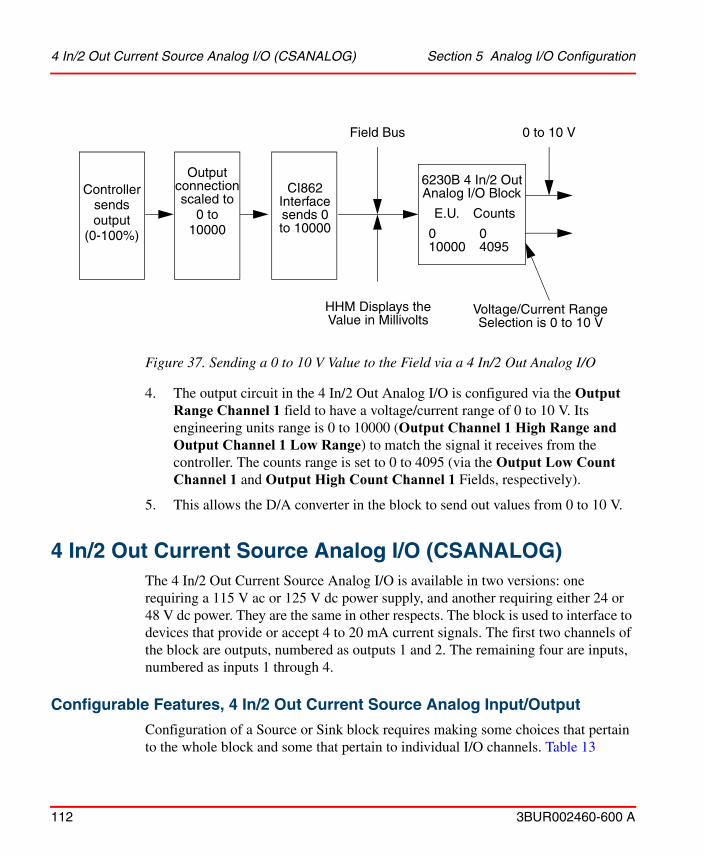
Figure 37. Sending a 0 to 10 V Value to the Field via a 4 In/2 Out Analog I/O
4 In/2 Out Current Source Analog I/O (CSANALOG) Section 5 Analog I/O Configuration
112 3BUR002460-600 A
4. The output circuit in the 4 In/2 Out Analog I/O is configured via the Output
Range Channel 1 field to have a voltage/current range of 0 to 10 V. Its engineering units range is 0 to 10000 (Output Channel 1 High Range and Output Channel 1 Low Range) to match the signal it receives from the controller. The counts range is set to 0 to 4095 (via the Output Low Count Channel 1 and Output High Count Channel 1 Fields, respectively).
5. This allows the D/A converter in the block to send out values from 0 to 10 V.
4 In/2 Out Current Source Analog I/O (CSANALOG)The 4 In/2 Out Current Source Analog I/O is available in two versions: one requiring a 115 V ac or 125 V dc power supply, and another requiring either 24 or 48 V dc power. They are the same in other respects. The block is used to interface to devices that provide or accept 4 to 20 mA current signals. The first two channels of the block are outputs, numbered as outputs 1 and 2. The remaining four are inputs, numbered as inputs 1 through 4.
Configurable Features, 4 In/2 Out Current Source Analog Input/Output
Configuration of a Source or Sink block requires making some choices that pertain to the whole block and some that pertain to individual I/O channels. Table 13
6230B 4 In/2 OutAnalog I/O Block
Counts
04095
E.U.
010000
0 to 10 VField Bus
HHM Displays theValue in Millivolts
Voltage/Current RangeSelection is 0 to 10 V
CI862Interfacesends 0to 10000
Outputconnectionscaled to
Controller
0 tosendsoutput
10000(0-100%)

Section 5 Analog I/O Configuration Configurable Features, 4 In/2 Out Current Source Analog
3BUR002460-600 A 113
summarizes the configurable items and lists their valid choices. The features noted with an asterisk (*) are similar for every type of TRIO unit and are described in Settings and Common Configurable Features on page 40. The Block Number and Baud Rate features are set by the HHM before adding a unit to the LAN and are then matched when configuring the CI862.
Table 13. Configurable Features of the 4 In/2 Out Current Source Analog I/O
Feature ChoicesConfiguration
Default
Block Level Features
Block Number (see Adding New Unit)
1 to 30 Set when placing New Unit.
Baud Rate 153.6K Standard, 153.6K Extended, 76.8K, 38.4K
See CI862 Settings tab.
Configuration Protection* enabled enabled
Automatic Download* True (Auto Download) True
BSM Controller* True (yes), False (no) False
BSM Present* True (yes), False (no) True
Input Filter16, 20, 33, 40, 67, 80, 100, 200, 400 mSec
400
Output Default* Time 2.5 or 10 seconds 2.5
Input Channel Features
Activate Channel x True (yes), False (no) True
High Count Channel x 0 to 25000 20000
Low Count Channel x 0 to 25000 4000
Report Faults Channel x True (yes), False (no) True
Channel X High Range -32767 to 32767 20000
Channel X Low Range -32767 to 32767 4000

Special Configuration Features, 4 In/2 Out Current Source Analog I/O Section 5 Analog I/O
114 3BUR002460-600 A
Special Configuration Features, 4 In/2 Out Current Source Analog I/O
An input is automatically subject to the Open Wire, Overrange, and Underrange diagnostics. These diagnostics are described in Output Overrange and Underrange on page 122, and should be considered prior to planning the I/O channels for the block.
The unit is configured by the CSANALOG hardware editor, Figure 38.
Output Channel Features
Output Activate Channel x True (yes), False (no) True
Output Default (OSP Value) Channel x
-32767 to 32767 4000
Output FB Enabled Channel x True (yes), False (no) True
Output High Count Channel x 0 to 25000 20000
Output Hold State (OSP Control) Channel x
True (yes), False (no) True
Output Low Count Channel x 0 to 25000 4000
Output Report Faults Channel x True (yes), False (no) True
Output Settle Time Channel x 0 to 255 mSec 0
Output Channel X High Range -32767 to 32767 20000
Output Channel X Low Range -32767 to 32767 4000
Table 13. Configurable Features of the 4 In/2 Out Current Source Analog I/O
Feature ChoicesConfiguration
Default

Figure 38. 4 In 2 Out Current Source Analog I/O Settings
Section 5 Analog I/O Configuration Special Configuration Features, 4 In/2 Out Current Source
3BUR002460-600 A 115
Input Filter Time
The Input Filter field specifies a filter time for the entire block. This becomes the time required to perform one analog to digital conversion for all inputs of the block. Input channel resolution increases as the conversion time is lengthened. The possible input filter time entries are listed in Table 14. 400 mSec is the default entry.
Table 14. Input Filter Times and Resolutions
Input Filter Time (mSec)
Resolution (A) Resolution (bits)Rejected
Frequencies (Hz)
16 12 11+ 60
20 10 11+ 50, 400
33 6 12+ 60

Special Configuration Features, 4 In/2 Out Current Source Analog I/O Section 5 Analog I/O
116 3BUR002460-600 A
Input Channels
Input channels 1 through 4 are configured as described in the following topics.
Input Channel Scaling Parameters
The current at an input is applied to an A/D converter in the block. The A/D converter translates the input current value into a digital number called counts using a ratio of one count for each microamp. For example, when the current is 8 mA, the A/D converter produces a counts value of 8000.
The scaling entries (Low Count Channel x, High Count Channel x, and Channel x High Range, Channel x Low Range) allow you to convert the counts to engineering units values to be put on the Field Bus.
The Low Count Channel x and High Count Channel x entries must be in the range of 0 to 25000. On a new block, they default to 4000 for the Low Count Channel x and 20000 for the High Count Channel x.
The Channel x High Range, Output Channel x High Range entries must be within +32767 to -32767. Output Channel x Low Range, Channel x Low Range, entries must be within +32767 to -32767 respectively. On a new block, the default is 4000 for Output Channel x Low Range and Channel x Low Range and 20000 for Channel x High Range, Output Channel x High Range.
The equation for calculating the engineering units of the input conversion is:
40 5 12+ 50, 400
67 3 13+ 60
80 2.5 13+ 50, 400
100 2 14 50, 60, 400
200 1 15 50, 60, 400
400 0.5 16 50, 60, 400
Table 14. Input Filter Times and Resolutions
Input Filter Time (mSec)
Resolution (A) Resolution (bits)Rejected
Frequencies (Hz)

EUC LC–
HC LC–-------------------- HU LU– LU+=
Section 5 Analog I/O Configuration Special Configuration Features, 4 In/2 Out Current Source
3BUR002460-600 A 117
where:
EU value in engineering units calculated and put on the Field Bus.
C actual counts from the A/D converter.
HC value for HI COUNTS.
LC value for LO COUNTS.
HU value for HI RANGE.
LU value for LO RANGE.
The software allows much flexibility in the choice of scaling ranges. However, it is often useful to choose the following ranges:
Low Counts = Low Range = 4000
High Counts = High Range = 20000
EU C=
With these values, the equation for calculating the engineering units reduces to:
that is,
Engineering Units Counts=
This results in a value in microamps being put on the Field Bus, that is, one microamp in the input becomes one engineering unit, so if the input is 8.5 mA, the engineering units is 8500.
Configuration Examples for the 4 In/2 Out Current Source Analog I/O on page 123, contains examples of scaling ranges.
Active Input Channel
Activate Channel x allows you to enable or disable a channel. The two possible choices are:

Special Configuration Features, 4 In/2 Out Current Source Analog I/O Section 5 Analog I/O
118 3BUR002460-600 A
True channel is wired and is used. (default entry).
False channel is not wired. False prevents spurious diagnostic messages from being issued for an unused channel.
Report Faults
Report Faults Channel x enables or disables fault reporting from the channel.
Valid entries are:
True enable fault reporting (default entry).
False disable fault reporting.
Before determining whether to enable or disable fault reporting for an analog input, you should consider both the features of TRIO and the control software. In some scenarios, you may want to use both the fault reporting techniques of TRIO and the control software. In other scenarios, you may want to disable TRIO fault reporting and use just the control software features.
If TRIO fault reporting for a channel is enabled and a fault occurs:
• The block automatically sends a fault message to the control software on the next available bus scan. The status of the TRIO input channel is latched at BAD.
• the control software sets the data quality of the information from the channel to BAD and activates a Bad Data Quality Alarm for the Result of the Analog Input (if alarm enabled).
• The TRIO channel remains at BAD until the operator enters a Clear Fault command (TRIO Command Aspect). If the condition has cleared, the channel goes to a GOOD status. If a fault condition still exists, the channel reports a fault to the control software again and stays BAD.
• When the channel status returns to GOOD, the control software Bad Data Quality Alarm on the channel can be cleared.
If TRIO fault reporting is disabled then the channel error would not be reported.

Section 5 Analog I/O Configuration Special Configuration Features, 4 In/2 Out Current Source
3BUR002460-600 A 119
Square Root Extraction
The square root extraction feature is not used. If square root extraction is needed, configure a loop with an analog input to accept the value from the block and a modified square root function to extract the square root of the signal.
Output Channel Configuration Fields
The two output channels are configured as described in the following topics.
When you configure an output, it is automatically subject to the Overrange, Underrange, and Feedback Error diagnostics. These diagnostics are described in Output Overrange and Underrange on page 122, and should be considered prior to planning the I/O channels for the block.
Output Channel Scaling Parameters
CI LU–
HU LU–-------------------- HC LC– LC+=
When the block receives a value in engineering units to be output to the field, it converts the value into a number called counts and applies the counts to the output D/A converter. The D/A converter translates the counts into an amount of current to be output using the ratio of one count to one microamp. For example, if the counts value is 4500, the output channel produces a current of 4.5 mA.
The scaling entries are made to the Output Low Count Channel x, Output High Count Channel x, and Output Channel x High Range and Output Channel x Low Range. For an output circuit, the block uses these entries to convert the number sent from the controller into a counts number that produces the correct output current when applied to the output D/A converter.
The equation to calculate the output counts is:
where
C counts to go to the A/D converter.
HC value for HI COUNTS.
LC value for LO COUNTS.
HU value for HI RANGE.

Special Configuration Features, 4 In/2 Out Current Source Analog I/O Section 5 Analog I/O
120 3BUR002460-600 A
LU value for LO RANGE.
I value in engineering units sent from the system.
The Output Low Count Channel x and Output High Count Channel x entries must be in the range of 0 to 24000. On a new block, they default to 4000 for the Output Low Count Channel x and 20000 for the Output High Count Channel x.
The Output Channel x High Range must be within +32767 to -32767 and Output Channel x Low Range must be within +32767 to-32767. On a new block, the default is 20000 and 4000 respectively.
The software allows much flexibility in the choice of scaling ranges. However, it is often useful to have an engineering units value scaled in microamps sent to the block from CCF and use the following ranges at the block:
Low Counts = Low Range = 4000
High Counts = High Range = 20000
C EU=
With these values, the equation to calculate the counts reduces to
that is,
Counts Engineering Units=
One count produces one microamp to the field. Thus a value of 9500 engineering units from CCF results in a signal of 9.5 mA being sent to the field.
Configuration Examples for the 4 In/2 Out Current Source Analog I/O on page 123, contains examples of scaling ranges.
Active Output Channels
Output Activate Channel x allows you to enable or disable a channel. The two possible choices are:
True channel is wired and is used. (Default entry).

Section 5 Analog I/O Configuration 4 In/2 Out Current Source Analog I/O Diagnostics
3BUR002460-600 A 121
False channel is not wired. False prevents spurious diagnostic messages from being issued for an unused channel.
Settle Time for Output Channels
Output Settle Time Channel x is used for the Feedback Error diagnostic for output channels. After a change in value is sent to an output, the block waits an amount of time equal to the entry in the corresponding Output Settle Time Channel x and checks the output. If it differs by more than 1% full scale from the commanded output, a Feedback Error diagnostic is reported. The Settle Time defaults to 0 mSec. A value of 0 in Output Settle Time Channel x specifies that the block checks the output immediately. You can change the Settle Time to any value in the range of 0 to 255 mSec. If this value is made too small, the block issues spurious diagnostics.
Output Feedback Enable
Output FB Enabled Channel x is used to enable or disable the Feedback diagnostic for an output. Valid entries are True (default) or False.
On some 4 In/2 Out Current Source Analog I/O (does not apply to those used in the 4 to 20 mA range), feedback data may be unstable close to 0 A. False Output Feedback Error diagnostics may be reported in some blocks if an output that has been commanded, defaulted, or forced to 0 A is changed to a non-zero level. Feedback data is stable when values above 100 A are commanded. If a false Output Feedback Error is reported, clear the fault. It is not reported again while the commanded output remains above 100 A. To avoid this situation, disable feedback checking for channels whose output is frequently set to less than 1 mA and re-enable checking after the output reaches a value greater than 1 mA.
4 In/2 Out Current Source Analog I/O Diagnostics
The block has the following diagnostics:
Open Wire
The Open Wire diagnostic detects an open wire at an input terminal. If the circuit current drops below 2 mA, the block sends an OPENWIRE message. Nothing is done to alter the actual input data.

4 In/2 Out Current Source Analog I/O Diagnostics Section 5 Analog I/O Configuration
122 3BUR002460-600 A
Underrange and Overrange
Depending on the analog input signal level and the scaling units, it is possible to calculate input values that exceed the 16 bits available. If this occurs, the block holds the value at its maximum level, and sends an appropriate diagnostic message.
Input Overrange
Signifies one of the following:
• The input value would be greater than +32,767 when converted to engineering units.
• The input voltage is outside of the A/D converter range (that is, greater than 25 mA).
Input Underrange
Signifies one of the following:
• The input value would be less than -32,767 when converted to engineering units.
• The input voltage is outside of the A/D converter range (that is, less than 0).
Output Overrange and Underrange
Occurs if conversion of the engineering units value sent by the controller exceeds the output circuit voltage limits. The output is clamped to the appropriate range limit to protect external hardware.
Output Overrange signifies the conversion from engineering units to counts would result in a value greater than 24 mA at the output.
Output Underrange signifies the conversion from engineering units results in a value less than 0.
Feedback Error
This is an output diagnostic that requires an entry be made to the Output Settle Time Channel x. The information in Configuration Examples for the 4 In/2 Out Current Source Analog I/O on page 123, describes how to configure this diagnostic.

Section 5 Analog I/O Configuration Configuration Examples for the 4 In/2 Out Current Source
3BUR002460-600 A 123
Configuration Examples for the 4 In/2 Out Current Source Analog I/O
The following examples show how the 4 In/2 Out Current Source Analog I/O can send values to analog inputs and receive them from analog outputs.
Example 1: Acquiring an Analog Value
Figure 39. Acquiring an Analog Input via a 4 In/2 Out Current Source Analog I/O Block
In the example shown in Figure 39, Input 2 of Unit 15 on Field Bus 1 acquires a pressure reading that can range between 15 and 50 psig. The inputs come from a 4 to 20 mA transmitter.
1. Since one microamp in the input is converted to one count, 4 mA, would be converted to 4000 counts by the A/D converter and the top of range, 20 mA, to 20000 counts. Therefore, 4000 is entered in the Low Count Channel 2 field and 20000 is entered in the High Count Channel 2 field.
2. The Channel 2 High Range field is set to 20000 and Channel 2 Low Range field id set to 4000.
3. In the controller, a loop is configured with an analog input that acquires the values from the block. The analog input counts range is set to 4000 to 20000 to
Transmitter
4 In/2 OutCS Analog I/O
Counts
400020000
E.U.
400020000
Analog Input
Counts
400020000
E.U.
1550
Restof
Loop
Pressure15 to 50 psig 4 to 20 mA Field Bus
HHM Displays theValue in Microamps
Block

Configuration Examples for the 4 In/2 Out Current Source Analog I/O Section 5 Analog I/O
124 3BUR002460-600 A
reflect the range of the signal it is receiving. Its engineering units range is set to 15 to 50 to reflect the actual pressure range being measured.
Example 2: Acquiring a Flow Value with Square Root Extraction Performed in the Controller
Figure 40. Acquiring a Flow Value with Square Root Extraction
Some flow transmitters require the square root of the transmitted signal to be extracted by system. The example in Figure 40 shows how to configure the database such that square root extraction is performed in the Controller, not in the 4 In/2 Out Current Source Analog I/O.
A differential pressure transmitter is sending signals from a flow that can range between 0 and 600 GPM. The signal is received by Input 4 on Unit 8 of Field Bus 3.
1. Since one microamp in the input is converted to one count, 4 mA, would be converted to 4000 counts by the A/D converter and the top of range, 20 mA, to 20000 counts. Therefore, 4000 is entered in the Low Count Channel 4 field and 20000 is entered in the High Count Channel 4 field.
2. The Channel 2 High Range field is set to 20000 and Channel 2 Low Range field is set to 4000. This allows the input to be converted to a A value that can be read with the HHM.
4 In/2 OutCS Analog I/O
Counts
400020000
E.U.
400020000
Analog Input
Counts
400020000
E.U.
0100
Flow0 to 600 GPM 4 to 20 mA Field Bus
HHM Displays theValue in Microamps
Modified SquareRoot
E.U.
0600
TransmitterBlock

Section 5 Analog I/O Configuration Configuration Examples for the 4 In/2 Out Current Source
3BUR002460-600 A 125
3. In the Controller, a loop is configured with an analog input to accept the value from the block and a modified square root function to extract the square root of the signal.
a. The Analog Input counts range is set to 4000 to 20000 to reflect the range of the signal it is receiving. Its engineering units range is set to 0 to 100 since it is required to produce a percent value to send to the modified square root.
b. The Modified Square Root accepts the percent value and extracts the square root. Its engineering units range is configured as 0 to 600 so that it produces a value equal to the actual flow value.
Example 3: Sending a 4 to 20 mA Output to the Field
Figure 41. Sending a 4 to 20 mA Signal to the Field via a 4 In/2 Out Current Source Analog I/O Block
In the example in Figure 41, a 4 to 20 mA signal is sent to the field via a 4 In/2 Out Current Source Analog I/O.
1. A loop in the Controller is configured to determine the value to output. It is terminated with an Analog Output.
2. The body of the loop sends a value of 0 to 100 engineering units to the Analog Output.
6231B 4 In/2 OutCS Analog I/O
Counts
400020000
E.U.
400020000
Analog Output
Counts
400020000
E.U.
0100
Application
4 to 20 mAField Bus
HHM Displays theValue in Microamps
Block

Configuration Examples for the 4 In/2 Out Current Source Analog I/O Section 5 Analog I/O
126 3BUR002460-600 A
3. The Analog Output converts this to a counts value of 4000 to 20000 that it sends on the Field Bus to the block. This allows the HHM to display the current value in microamps.
4. The engineering units range for the output channel is set to 4000 and 20000 (Output Channel 2 Low Range field and Output Channel 2 High Range field) to match the signal it receives from the controller. The counts range is set to 4000..20000 (via the Output Low Count Channel 2 and Output High Count Channel 2 fields).
5. This allows the D/A converter in the block to send out values from 4 to 20 mA.

Section 5 Analog I/O Configuration 6 Circuit Current Source Analog Input (CSANAINP)
3BUR002460-600 A 127
6 Circuit Current Source Analog Input (CSANAINP)The 6 Circuit Current Source Analog Input, is available in two versions: one requiring a 115 V ac or 125 V dc power supply, and another requiring either 24 or 48 V dc power. They are the same in other respects. The block is used to interface to devices that provide 4 to 20 mA current signals. The CSANAINP unit has six inputs, numbered as inputs 1 through 6.
Configurable Features, 6 Circuit Current Source Analog Input
Configuration of a current source analog input requires making some choices that pertain to the whole unit and some that pertain to individual channels. Table 15 summarizes the configurable items and lists their valid choices. The features noted with an asterisk (*) are similar for every type of TRIO unit and are described in Settings and Common Configurable Features on page 40. The Block Number and Baud Rate features are set by the HHM before adding a unit to the LAN and are then matched when configuring the CI862.
Table 15. Configurable Features of the 6 Circuit Current Source Analog Input
Feature ChoicesConfiguration
Default
Block Level Features
Block Number (see Adding New Unit)
1 to 30 Set when placing New Unit.
Baud Rate 153.6K Standard, 153.6K Extended, 76.8K, 38.4K
See CI862 Settings tab.
Configuration Protection* enabled enabled
Automatic Download* True (Auto Download) True
BSM Controller* True (yes), False (no) False
BSM Present* True (yes), False (no) False
Input Filter16, 20, 33, 40, 67, 80, 100, 200, 400 mSec
400
Output Default* Time 2.5 or 10 seconds 2.5
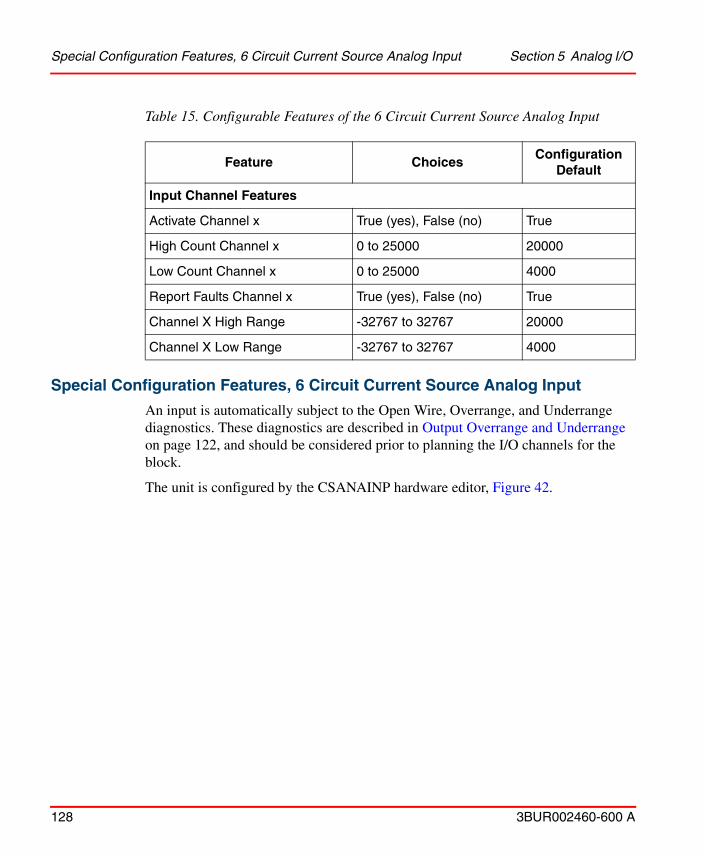
Special Configuration Features, 6 Circuit Current Source Analog Input Section 5 Analog I/O
128 3BUR002460-600 A
Special Configuration Features, 6 Circuit Current Source Analog Input
An input is automatically subject to the Open Wire, Overrange, and Underrange diagnostics. These diagnostics are described in Output Overrange and Underrange on page 122, and should be considered prior to planning the I/O channels for the block.
The unit is configured by the CSANAINP hardware editor, Figure 42.
Input Channel Features
Activate Channel x True (yes), False (no) True
High Count Channel x 0 to 25000 20000
Low Count Channel x 0 to 25000 4000
Report Faults Channel x True (yes), False (no) True
Channel X High Range -32767 to 32767 20000
Channel X Low Range -32767 to 32767 4000
Table 15. Configurable Features of the 6 Circuit Current Source Analog Input
Feature ChoicesConfiguration
Default

Figure 42. 6 Circuit Current Source Analog Input Settings
Section 5 Analog I/O ConfigurationSpecial Configuration Features, 6 Circuit Current Source Analog
3BUR002460-600 A 129
Input Filter Time
The Input Filter field specifies a filter time for the entire block. This becomes the time required to perform one analog to digital conversion for all inputs of the block. Input channel resolution increases as the conversion time is lengthened. The possible input filter time entries are listed in Table 16. 400 mSec is the default entry.

Table 16. Input Filter Times and Resolutions
Input Filter Time (mSec)
Resolution (A) Resolution (bits)Rejected
Frequencies (Hz)
16 12 11+ 60
20 10 11+ 50, 400
33 6 12+ 60
40 5 12+ 50, 400
67 3 13+ 60
80 2.5 13+ 50, 400
100 2 14 50, 60, 400
200 1 15 50, 60, 400
400 0.5 16 50, 60, 400
Special Configuration Features, 6 Circuit Current Source Analog Input Section 5 Analog I/O
130 3BUR002460-600 A
Input Channels
Input channels 1 through 6 are configured as described in the following topics.
Input Channel Scaling Parameters
The current at an input is applied to an A/D converter in the block. The A/D converter translates the input current value into a digital number called counts using a ratio of one count for each microamp. For example, when the current is 8 mA, the A/D converter produces a counts value of 8000.
The scaling entries (Low Count Channel x, High Count Channel x, and Channel x High Range, Channel x Low Range) allow you to convert the counts to engineering units values to be put on the Field Bus.
The Low Count Channel x and High Count Channel x entries must be in the range of 0 to 25000. On a new block, they default to 4000 for the Low Count Channel x and 20000 for the High Count Channel x.

EUC LC–
HC LC–-------------------- HU LU– LU+=
Section 5 Analog I/O ConfigurationSpecial Configuration Features, 6 Circuit Current Source Analog
3BUR002460-600 A 131
The Channel x High Range entry must be within -32767 to +32767 and Channel x Low Range entry must be within -32767 to +32767. On a new block, the default is 20000 and 4000 respectively for High Range and Low Range parameters.
The equation for calculating the engineering units of the input conversion is:
where:
EU value in engineering units calculated and put on the Field Bus.
C actual counts from the A/D converter.
HC value for HI COUNTS.
LC value for LO COUNTS.
HU value for HI RANGE.
LU value for LO RANGE.
The software allows much flexibility in the choice of scaling ranges. However, it is often useful to choose the following ranges:
Low Counts = Low Range = 4000
High Counts = High Range = 20000
EU C=
With these values, the equation for calculating the engineering units reduces to:
that is,
Engineering Units Counts=
This results in a value in microamps being put on the Field Bus, that is, one microamp in the input becomes one engineering unit, so if the input is 8.5 mA, the engineering units is 8500.
Configuration Examples for the 4 In/2 Out Current Source Analog I/O on page 123, contains examples of scaling ranges.

Special Configuration Features, 6 Circuit Current Source Analog Input Section 5 Analog I/O
132 3BUR002460-600 A
Active Input Channel
Activate Channel x allows you to enable or disable a channel. The two possible choices are:
True channel is wired and is used. (default entry).
False channel is not wired. False prevents spurious diagnostic messages from being issued for an unused channel.
Report Faults
Report Faults Channel x enables or disables fault reporting from the channel.
Valid entries are:
True enable fault reporting (default entry).
False disable fault reporting.
Before determining whether to enable or disable fault reporting for an analog input, you should consider both the features of TRIO and the control software. In some scenarios, you may want to use both the fault reporting techniques of TRIO and the control software. In other scenarios, you may want to disable TRIO fault reporting and use just the control software features.
If TRIO fault reporting for a channel is enabled and a fault occurs:
• The block automatically sends a fault message to the control software on the next available bus scan. The status of the TRIO input channel is latched at BAD.
• the control software sets the data quality of the information from the channel to BAD and activates a Bad Data Quality Alarm for the Result of the Analog Input (if alarm enabled).
• The TRIO channel remains at BAD until the operator enters a Clear Fault command (TRIO Command Aspect). If the condition has cleared, the channel goes to a GOOD status. If a fault condition still exists, the channel reports a fault to the control software again and stays BAD.
• When the channel status returns to GOOD, the control software Bad Data Quality Alarm on the channel can be cleared.

Section 5 Analog I/O Configuration 6 Circuit Current Source Analog Input Diagnostics
3BUR002460-600 A 133
If TRIO fault reporting is disabled then the channel error would not be reported.
6 Circuit Current Source Analog Input Diagnostics
The block has the following diagnostics:
Open Wire
The Open Wire diagnostic detects an open wire at an input terminal. If the circuit current drops below 2 mA, the block sends an OPENWIRE message. Nothing is done to alter the actual input data.
Underrange and Overrange
Depending on the analog input signal level and the scaling units, it is possible to calculate input values that exceed the 16 bits available. If this occurs, the block holds the value at its maximum level, and sends an appropriate diagnostic message.
Input Overrange
Signifies one of the following:
• The input value would be greater than +32,767 when converted to engineering units.
• The input voltage is outside of the A/D converter range (that is, greater than 25 mA).
Input Underrange
Signifies one of the following:
• The input value would be less than -32,767 when converted to engineering units.
• The input voltage is outside of the A/D converter range (that is, less than 0).

Configuration Examples for the 6 Circuit Current Source Analog Input Section 5 Analog I/O
134 3BUR002460-600 A
Configuration Examples for the 6 Circuit Current Source Analog Input
The following examples show how the Current Source Analog Input can send values to analog inputs and receive them from analog outputs.
Example 1: Acquiring an Analog Value
Figure 43. Acquiring an Analog Input via a Current Source Analog Input Block
In the example shown in Figure 43, Input 2 of Unit 15 on Field Bus 1 acquires a pressure reading that can range between 15 and 50 psig. The inputs come from a 4 to 20 mA transmitter.
1. Since one microamp in the input is converted to one count, 4 mA, would be converted to 4000 counts by the A/D converter and the top of range, 20 mA, to 20000 counts. Therefore, 4000 is entered in the Low Count Channel 2 field and 20000 is entered in the High Count Channel 2 field.
2. The Channel 2 High Range field is set to 20000 and Channel 2 Low Range field is set to 4000.
3. In the controller, a loop is configured with an analog input that acquires the values from the block. The analog input counts range is set to 4000 to 20000 to reflect the range of the signal it is receiving. Its engineering units range is set to 15 to 50 to reflect the actual pressure range being measured.
Transmitter
6 CircuitCS Analog Input
Counts
400020000
E.U.
400020000
Analog Input
Counts
400020000
E.U.
1550
Restof
Loop
Pressure15 to 50 psig 4 to 20 mA Field Bus
HHM Displays theValue in Microamps
Block

Section 5 Analog I/O Configuration Configuration Examples for the 6 Circuit Current Source Analog
3BUR002460-600 A 135
Example 2: Acquiring a Flow Value with Square Root Extraction Performed in the Controller
Figure 44. Acquiring a Flow Value with Square Root Extraction
Some flow transmitters require the square root of the transmitted signal to be extracted by system. The example in Figure 44 shows how to configure the database such that square root extraction is performed in the Controller, not in the 6 Circuit Current Source Analog Input.
A differential pressure transmitter is sending signals from a flow that can range between 0 and 600 GPM. The signal is received by Input 4 on Unit 8 of Field Bus 3.
1. Since one microamp in the input is converted to one count, 4 mA, would be converted to 4000 counts by the A/D converter and the top of range, 20 mA, to 20000 counts. Therefore, 4000 is entered in the Low Count Channel 4 field and 20000 is entered in the High Count Channel 4 field.
2. The Channel 2 High Range field is set to 20000 and Channel 2 Low Range Field is set to 4000. This allows the input to be converted to a A value that can be read with the HHM.
3. In the Controller, a loop is configured with an analog input to accept the value from the block and a modified square root function to extract the square root of the signal.
6 CircuitCS Analog Input
Counts
400020000
E.U.
400020000
Analog Input
Counts
400020000
E.U.
0100
Flow0 to 600 GPM 4 to 20 mA Field Bus
HHM Displays theValue in Microamps
Modified SquareRoot
E.U.
0600
TransmitterBlock

Configuration Examples for the 6 Circuit Current Source Analog Input Section 5 Analog I/O
136 3BUR002460-600 A
a. The Analog Input counts range is set to 4000 to 20000 to reflect the range of the signal it is receiving. Its engineering units range is set to 0 to 100 since it is required to produce a percent value to send to the modified square root.
b. The Modified Square Root accepts the percent value and extracts the square root. Its engineering units range is configured as 0 to 600 so that it produces a value equal to the actual flow value.

Section 5 Analog I/O Configuration 6 Circuit Current Source Analog Output (CSANAOUT)
3BUR002460-600 A 137
6 Circuit Current Source Analog Output (CSANAOUT)The 6236B 6 Circuit Current Source Analog Output, is available in two versions: one requiring a 115 V ac or 125 V dc power supply, and another requiring either 24 or 48 V dc power. They are the same in other respects. The block is used to interface to devices that accept 4 to 20 mA current signals. The CSANAOUT unit has six outputs, numbered as outputs 1 through 6. You can also use outputs 5 and 6 for voltage applications.
Configurable Features, 6 Circuit Current Source Analog Output
Configuration of a current source analog output requires making some choices that pertain to the whole unit and some that pertain to individual channels. Table 17 summarizes the configurable items and lists their valid choices. The features noted with an asterisk (*) are similar for every type of TRIO unit and are described in Settings and Common Configurable Features on page 40. The Block Number and Baud Rate features are set by the HHM before adding a unit to the LAN and are then matched when configuring the CI862.
Table 17. Configurable Features of the 6 Circuit Current Source Analog Output
Feature ChoicesConfiguration
Default
Block Level Features
Block Number (see Adding New Unit)
1 to 30 Set when placing New Unit.
Baud Rate 153.6K Standard, 153.6K Extended, 76.8K, 38.4K
See CI862 Settings tab.
Configuration Protection* enabled enabled
Automatic Download* True (Auto Download) True
BSM Controller* True (yes), False (no) False
BSM Present* True (yes), False (no) False
Output Default* Time 2.5 or 10 seconds 2.5

Special Configuration Features, 6 Circuit Current Source Analog Output Section 5 Analog I/O
138 3BUR002460-600 A
Special Configuration Features, 6 Circuit Current Source Analog Output
Configured outputs are automatically subject to the Underrange, Overrange and Feedback Error diagnostics. Detailed information about the diagnostics is provided in 4 In/2 Out Analog I/O Diagnostics on page 107.
The unit is configured by the hardware editor for the CSANAOUT, Figure 45.
Output Channel Features
Activate Channel x True (yes), False (no) True
FB Enabled Channel x True (yes), False (no) True
Default (OSP Value) Channel x -32767 to 32767 4000
High Count Channel x 0 to 25000 20000
Hold State (OSP Control) Channel x
True (yes), False (no) True
Low Count Channel x 0 to 25000 4000
Report Faults Channel x True (yes), False (no) True
Settle Time Channel x 0 to 255 mSec 0
Channel X High Range -32767 to 32767 20000
Channel X Low Range -32767 to 32767 4000
Table 17. Configurable Features of the 6 Circuit Current Source Analog Output
Feature ChoicesConfiguration
Default

Figure 45. 6 Circuit Current Source Analog Output Settings
Section 5 Analog I/O ConfigurationSpecial Configuration Features, 6 Circuit Current Source Analog
3BUR002460-600 A 139
Output Channel Scaling Parameters
When the block receives a value in engineering units to be output to the field, it converts the value into a number called counts and applies the counts to the output D/A converter. The D/A converter translates the counts into an amount of current to be output using the ratio of one count to one microamp. For example, if the counts value is 4500, the output channel produces a current of 4.5 mA.
The scaling entries are made to the Output Low Count Channel x, Output High Count Channel x, Channel x High Range and Channel x Low Range. For an output circuit, the block uses these entries to convert the number sent from the controller into a counts number that produces the correct output current when applied to the output D/A converter.

CI LU–
HU LU–-------------------- HC LC– LC+=
Special Configuration Features, 6 Circuit Current Source Analog Output Section 5 Analog I/O
140 3BUR002460-600 A
The equation to calculate the output counts is:
where
C counts to go to the A/D converter.
HC value for HI COUNTS.
LC value for LO COUNTS.
HU value for HI RANGE.
LU value for LO RANGE.
I value in engineering units sent from the system.
The Output Low Count Channel x and Output High Count Channel x entries must be in the range of 0 to 24000. On a new block, they default to 4000 for the Output Low Count Channel x and 20000 for the Output High Count Channel x.
The Channel x High Range must be in the range of -32767 to +32767 and Channel x Low Range must be in the range of -32767 to 32767. On a new block, the default is 4000 and 20000 for Channel x Low Range and Channel x High Range respectively.
The software allows much flexibility in the choice of scaling ranges. However, it is often useful to have an engineering units value scaled in microamps sent to the block from CCF and use the following ranges at the block:
Low Counts = Low Range = 4000
High Counts = High Range = 20000
C EU=
With these values, the equation to calculate the counts reduces to
that is,
Counts Engineering Units=

Section 5 Analog I/O ConfigurationSpecial Configuration Features, 6 Circuit Current Source Analog
3BUR002460-600 A 141
One count produces one microamp to the field. Thus a value of 9500 engineering units from CCF results in a signal of 9.5 mA being sent to the field.
Configuration Examples for the 6 Circuit Current Source Analog Output on page 142, contains examples of scaling ranges.
Active Output Channels
Output Activate Channel x allows you to enable or disable a channel. The two possible choices are:
True channel is wired and is used. (Default entry).
False channel is not wired. Prevents spurious diagnostic messages from being issued for an unused channel.
Settle Time for Output Channels
Output Settle Time Channel x is used for the Feedback Error diagnostic for output channels. After a change in value is sent to an output, the block waits an amount of time equal to the entry in the corresponding Output Settle Time Channel x and checks the output. If it differs by more than 1% full scale from the commanded output, a Feedback Error diagnostic is reported. The Settle Time defaults to 0 mSec. A value of 0 in Output Settle Time Channel x specifies that the block checks the output immediately. You can change the Settle Time to any value in the range of 0 to 255 mSec. If this value is made too small, the block issues spurious diagnostics.
Output Feedback Enable
Output FB Enabled Channel x is used to enable or disabled the Feedback diagnostic for an output. Valid entries are True (default) or False.

6 Circuit Current Source Analog Output Diagnostics Section 5 Analog I/O Configuration
142 3BUR002460-600 A
6 Circuit Current Source Analog Output Diagnostics
The block has the following diagnostics:
Output Overrange and Underrange
Occurs if conversion of the engineering units value sent by the controller exceeds the output circuit voltage limits. The output is clamped to the appropriate range limit to protect external hardware.
Output Overrange signifies the conversion from engineering units to counts would result in a value greater than 24 mA at the output.
Output Underrange signifies the conversion from engineering units results in a value less than 0.
Feedback Error
This is an output diagnostic that requires an entry be made to the Output Settle Time Channel x. The information in Configuration Examples for the 6 Circuit Current Source Analog Output on page 142, describes how to configure this diagnostic.
Configuration Examples for the 6 Circuit Current Source Analog Output
The following example shows how the 6 Circuit Current Source Analog Output Block can send values to Analog Outputs.
Example 3: Sending a 4 to 20 mA Output to the Field
In the example in Figure 46, a 4 to 20 mA signal is sent to the field via a 4 In/2 Out Current Source Analog I/O.

Figure 46. Sending a 4 to 20 mA Signal to the Field via a 6 Circuit Current Source Analog Output Block
Section 5 Analog I/O Configuration Configuration Examples for the 6 Circuit Current Source Analog
3BUR002460-600 A 143
1. A loop in the Controller is configured to determine the value to output. It is terminated with an Analog Output.
2. The body of the loop sends a value of 0 to 100 engineering units to the Analog Output.
3. The Analog Output converts this to a counts value of 4000 to 20000 that it sends on the Field Bus to the block. This allows the HHM to display the current value in microamps.
4. The engineering units range for the output channel is set to 4000..20000 (Channel 2 Low Range field and Channel 2 High Range field) to match the signal it receives from the controller. The counts range is set to 4000..20000 (via the Output Low Count Channel 2 and Output High Count Channel 2 fields).
5. This allows the D/A converter in the block to send out values from 4 to 20 mA.
6 Circuit CSAnalog Output
Counts
400020000
E.U.
400020000
Analog Output
Counts
400020000
E.U.
0100
Application
4 to 20 mAField Bus
HHM Displays theValue in Microamps
Block

6 Circuit Thermocouple Input (TC) Section 5 Analog I/O Configuration
144 3BUR002460-600 A
6 Circuit Thermocouple Input (TC)The 6232B 6 Circuit Thermocouple Input, is available in two versions: one requiring a 115 V ac power supply, and another requiring either 24 or 48 V dc power. The blocks are the same in other respects. The block has six input channels, in three isolated groups of two channels apiece. Each input can be used with thermocouple types J, K, T, E, B, R, S, and N. A linear (L) option allows for millivolt inputs in the range of -25.00 to 150.00 mV.
Configurable Features, 6 Circuit Thermocouple Input
Configuration of a thermocouple input requires making some choices that pertain to the whole unit and some that pertain to individual channels. Table 18 summarizes the configurable items and lists their valid choices. The features noted with an asterisk (*) are similar for every type of TRIO unit and are described in Settings and Common Configurable Features on page 40. The Block Number and Baud Rate features are set by the HHM before adding a unit to the LAN and are then matched when configuring the CI862.
Table 18. Configurable Features of the 6 Circuit Thermocouple Input
Feature ChoicesConfiguration
Default
Block Level Features
Block Number (see Adding New Unit)
1 to 30 Set when placing New Unit.
Baud Rate 153.6K Standard, 153.6K Extended, 76.8K, 38.4K
See CI862 Settings tab.
Configuration Protection* enabled enabled
Automatic Download* True (Auto Download) True
BSM Controller* True (yes), False (no) False
BSM Present* True (yes), False (no) False
Eng Units DEGC, DEGF, MV DEGC

Section 5 Analog I/O Configuration Special Configuration Features, 6 Circuit Thermocouple Input
3BUR002460-600 A 145
Special Configuration Features, 6 Circuit Thermocouple Input
Configured outputs are automatically subject to the Underrange, Overrange and Feedback Error diagnostics. Detailed information about the diagnostics is provided in 4 In/2 Out Analog I/O Diagnostics on page 107.
The unit is configured by the hardware editor for the TC, Figure 47.
Input Channel Features
Activate Channel x True (yes), False (no) True
Compensation Channel x Internal, XJA, XJV, user-defined
Internal
Field Offset Channel x 100 0
Report Faults Channel x True (yes), False (no) True
Thermocouple Type Channel x J, K, T, E, B, R, S, N, L (Linear)
J
Users Value Channel x 327.67 0.0
Table 18. Configurable Features of the 6 Circuit Thermocouple Input
Feature ChoicesConfiguration
Default

Figure 47. 6 Circuit Thermocouple Input Settings
Special Configuration Features, 6 Circuit Thermocouple Input Section 5 Analog I/O Configuration
146 3BUR002460-600 A
Engineering Units
The ENG UNITS Field determines the type of conversion that is performed on the input. The values put on the Field Bus are scaled in these units and multiplied by 10, for example, a temperature of 130.5 causes 1305 to be put on the Field Bus.
Valid entries are:
DEGC degrees Celsius.
DEGF degrees Fahrenheit.
MV millivolts. This entry is used when all inputs to the block come from millivolt sources (that is, the entry in the CHAN n TC TYPE Field is L).

Section 5 Analog I/O Configuration Special Configuration Features, 6 Circuit Thermocouple Input
3BUR002460-600 A 147
Thermocouple Type for the Channel
The CHAN n TC TYPE Field is used to specify the type of thermocouple.
Valid entries are:
J (default), K, T, E, B, R, S, N, L (Linear, used for millivolt inputs, treats 1 mV as equal to 10× C).
Channel Compensation
The CHAN n COMPENSATION Field determines the type of junction compensation to be used. You should be familiar with the information in the installation manual before making an entry to this field.
Valid entries are:
User-defined Compensation Value for the Channel
Used to specify the amount of compensation in terms of millivolts to be made to the lookup table when the Compensation type is USER DEFINED. Thermocouple connections and configuration requirements for the different compensation types are described in the installation manual.
Valid entry is:
a number of millivolts in the range of -327.67 to +327.67
INTERNAL Use the signal from the temperature sensor on the block terminal strip for the compensation (default value).
XJA Use the current signal at the +XJI and -XJI terminals of the thermocouple group for the compensation.
XJV Use the voltage signal at the +XJV and -XJV terminals of the thermocouple group for the compensation.
USER DEFINED Uses the fixed configured value that is entered through the USER VALUE Field for the compensation.

6 Circuit Thermocouple Input Diagnostics Section 5 Analog I/O Configuration
148 3BUR002460-600 A
Field Offset for the Channel
Allows a correction term to be added to the temperature. For example, if it is found that the measured temperature is consistently 2 degrees low, this field would be set to 2.
Valid entries are:
±100
Report Faults for the Channel
Enables or disables fault reporting from the channel.
Valid entries are:
YES enable fault reporting (default entry).
NO disable fault reporting.
Active Input Channel
Allows you to tell the software whether or not the channel is used. The two possible choices are:
YES channel is wired and is used. (default entry).
NO channel is not wired. Prevents spurious diagnostic messages from being issued for an unused channel.
6 Circuit Thermocouple Input Diagnostics
The block has the following diagnostics.
Input Underrange
Signifies the input is lower than the lowest value in the thermocouple lookup table.
Input Overrange
Indicates the input is greater than the largest value in the thermocouple lookup table

Section 5 Analog I/O Configuration Configuration Examples for the 6 Circuit Thermocouple Input
3BUR002460-600 A 149
Input Open Wire
Detects when the thermocouple measurement exceeds the highest value expected. This diagnostic is for the detection of open thermocouples.
Internal Channel Fault
Detects when the internal cold junction sensor indicates an ambient temperature outside the specified range.
Configuration Examples for the 6 Circuit Thermocouple Input
This section contains examples of the techniques needed to handle inputs from the 6 Circuit Thermocouple Input.
Temperature Input via a Thermocouple
Figure 48. Configuration Example, Thermocouple Input
The example in Figure 48 shows a thermocouple connected to Channel 3 of the TRIO block 6 on Field Bus 1.
1. A thermocouple senses a temperature (85.1× C in this instance) and sends a millivolt signal to the block.
Temperature
Thermocouplesends signal
Thermocouple Block linearizes the signal
junction effects. It puts
CI862Interfacesends
counts to
The counts value onthe Field Bus is 851
HHM displays 85.1for the value
Resultis
85.1
to the block.
85.1
an integer value intenths of degrees onto
and compensates for
the Field Bus.controller
Controller
inconvertscounts
ControlBuilder
Application

Configuration Examples for the 6 Circuit Thermocouple Input Section 5 Analog I/O Configuration
150 3BUR002460-600 A
2. The Thermocouple Input block linearizes the signal and converts it to the appropriate temperature units. For increased resolution, this number is put on the Field Bus as an integer value of tenths of degrees. For example, a temperature of 85.1 degrees results in a counts value of 851 being put on the Field Bus.
3. The CI862 is configured to recognize the input as coming from Thermocouple Input 3 on Block 6 of Field Bus 1 and normalizes the value (divide the input by 10).
4. The Control Builder sees the results as 85.1.
Millivolt Input when Thermocouple Block has Eng Units of MV
Figure 49. Configuration Example, Millivolt Input with MV Engineering Units
The example in Figure 49 shows a millivolt signal connected to Channel 3 of the TRIO block 6 on Field Bus 1.
1. The CI862 is configured to be the first interface (Field Bus 1) with an I/O Unit 6 (TC).
2. A millivolt signal is generated (29.00 in this instance) and the signal is sent to the block.
Millivolts
Millivoltsignal sent
Thermocouple Block is configured for MV
The counts value onthe Field Bus is 2900
HHM displays 290.0for the value
to the block.
= 29.00
puts an integer value inhundredths of millivolts
engineering units and
onto the Field Bus.
linear (L) linearization. It
CI862Interfacesends
counts to
Resultis
290.0
controller
Controller
inconvertscounts
ControlBuilder
Application

Section 5 Analog I/O Configuration Configuration Examples for the 6 Circuit Thermocouple Input
3BUR002460-600 A 151
3. The Thermocouple Input block converts the millivolt signal to an integer value of hundredths of mV (Thermocouple Type Channel 3 = L and the Eng Units = MV result is 10x10). For example, an input of 29.00 results in a counts value of 2900 being put on the Field Bus. Note that the HHM displays 290.0 as the value.
4. The controller is configured to recognize the input as coming from Thermocouple Input 3 on Block 6 of Field Bus 1 and normalizes the value (divides the input by 10) so the input, in the range of 0 to 100 millivolts, becomes a range of 0 to 1000 for the Result.
5. The Control Builder sees the results as 290.0.
Millivolt Input when Thermocouple Block has Eng Units of DEGC
Figure 50. Configuration Example, Millivolt Input with DEGC Engineering Units
The example in Figure 50 shows a millivolt signal connected to Channel 3 of the TRIO block 6 on Field Bus 1.
1. The CI862 is configured to be the first interface (Field Bus 1) with an I/O Unit 6 (TC).
2. A millivolt signal is generated (29.00 in this instance) and the signal is sent to the block.
Millivolts
Millivoltsignal sent
Thermocouple Block is configured for DEGC
The counts value onthe Field Bus is 2900
HHM displays 290.0for the value
to the block.
= 29.00
It puts a value intenths of DEGC onto
and linear linearization.
the Field Bus.
CI862Interfacesends
counts to
Resultis
290.0°C
controller
Controller
inconvertscounts
ControlBuilder
Application

Configuration Examples for the 6 Circuit Thermocouple Input Section 5 Analog I/O Configuration
152 3BUR002460-600 A
3. When the signal arrives at the block, 1 mV is treated as 10× C. For example, a 29.00 millivolt signal is treated as 290.0× C. The signal is put on the Field Bus as an integer value of tenths of degrees Celsius, for example, 2900 counts for 290.0× C.The configuration settings are: Thermocouple Type Channel 3 = L and the Eng Units = DEGC. Note that the HHM displays 290.0 as the value.
The entries required to remove the effects of the cold junction compensation sensor are.
Compensation Channel 3 User Defined
User Value Channel 3 0
Field Offset Channel 3 Leave at 0 initially. You can enter a number into this field later to tune the measurement.
4. The controller is configured to recognize the input as coming from Thermocouple Input 3 on Block 6 of Field Bus 1 and normalizes the value (divides the input by 10) so the input, in the range of 0 to 100 millivolts, becomes a range of 0 to 1000 × C for the Result.
For DEGF, the temperature goes through a Celsius to Fahrenheit conversion, for example, multiply by 9/5 then add 32. To continue the example 290.0 C becomes 554.0 F. The counts put on the Field Bus are in terms of tenths of degrees Fahrenheit, for example, 554.0 yields 5540 counts.
5. The Control Builder sees the results as 290.0× C.

Section 5 Analog I/O Configuration 6 Circuit RTD Input (RTD)
3BUR002460-600 A 153
6 Circuit RTD Input (RTD)The 6233B 6 Circuit RTD Input is used to monitor temperature with Resistive Temperature Detectors (RTDs) connected to the inputs. The blocks are available in two versions: one uses a 115 V ac or 125 V dc power supply, the other requires either 24 or 48 V dc power. They are the same in other respects.
Configurable Features, 6 Circuit RTD Input
Configuration of a RTD input requires making some choices that pertain to the whole unit and some that pertain to individual channels. Table 19 summarizes the configurable items and lists their valid choices. The features noted with an asterisk (*) are similar for every type of TRIO unit and are described in Settings and Common Configurable Features on page 40. The Block Number and Baud Rate features are set by the HHM before adding a unit to the LAN and are then matched when configuring the CI862.
Table 19. Configurable Features of the 6 Circuit RTD Input
Feature ChoicesConfiguration
Default
Block Level Features
Block Number (see Adding New Unit)
1 to 30 Set when placing New Unit.
Baud Rate 153.6K Standard, 153.6K Extended, 76.8K, 38.4K
See CI862 Settings tab.
Configuration Protection* enabled enabled
Automatic Download* True (Auto Download) True
Input Filter 400, 800, 1600 mSec 400
Eng Units DEGC, DEGF, OHMS DEGC
Input Channel Features
Activate Channel x True (yes), False (no) True
Alpha Channel x .00100 to .00700 0.00385(1)

Special Configuration Features, 6 Circuit RTD Input Section 5 Analog I/O Configuration
154 3BUR002460-600 A
Special Configuration Features, 6 Circuit RTD Input
When you configure an input for this block, it is automatically subject to a number of diagnostics. Detailed information about the diagnostics is provided in 6 Circuit RTD Input Diagnostics on page 157.
The unit is configured by the hardware editor for the RTD, Figure 51.
Input Filter Time
The Input Filter entry determines how frequently the block transmits new values for all six inputs. Filters integrate input values over time to reject noise. The available filter time choices are: 400 mSec (14 bit resolution), 800 mSec (15 bit resolution), or 1600 mSec (16 bit resolution).
Engineering Units
The Eng Units entry specifies the engineering units for all RTD inputs. The possible choices are DEGC, DEGF, or OHMS. The values are put on the Field Bus in tenths of these units, for example, a temperature of 135.9 causes 1359 to be put on the bus.
Linearization
The Linearization entry determines how the channel converts the resistance value from the RTD into degrees.
Linearization Channel x Platinum, Nickel, Copper Platinum
Report Faults Channel x True (yes), False (no) True
Resistance Channel x 5.0 to 2000.0 100.0
(1) Default alpha, .00385, is for a DIN 43760 platinum element.
Table 19. Configurable Features of the 6 Circuit RTD Input
Feature ChoicesConfiguration
Default

Figure 51. 6 Circuit RTD Input Settings
Section 5 Analog I/O Configuration Special Configuration Features, 6 Circuit RTD Input
3BUR002460-600 A 155
Possible entries are:
Platinum used for RTDs with platinum elements. Inputs are linearized according to the DIN 43760 standard (R100C/R0C = 1.3850).
Nickel used for RTDs with nickel elements. Inputs are linearized according to the DIN 43760 standard (R100C/R0C = 1.6180).
Copper used for RTDs with copper elements. Inputs are linearized using a straight line approximation based on the RTD resistance and Alpha.

Special Configuration Features, 6 Circuit RTD Input Section 5 Analog I/O Configuration
156 3BUR002460-600 A
RTD Resistance
The Resistance entry specifies the nominal resistance at 0 C of the RTD connected to each input. This information is available from the RTD manufacturer, or determined by actual measurement.
Alpha Value
The Alpha entry specifies the alpha value of the RTD in micro-ohms per ohm-degrees Celsius for each input. This information is available from the RTD manufacturer. For example:
Alpha = 0.003850 for DIN 43760 platinum
RTD Resistance at 100° C RTD Resistance at 0° C–
100 RTD Resistance at 0° C ---------------------------------------------------------------------------------------------------------------=
It is best to use the alpha value in the RTD documentation. However, you can calculate the alpha value using the following equation from IEC 751.
Report Faults
The Report Faults entry enables or disables fault reporting from the channel.
Valid entries are:
YES enable fault reporting (default entry).
NO disable fault reporting.
Activate Input
The Activate entry allows you to tell the software whether or not the channel is used. The possible choices are:
YES channel is wired and is used (default entry).
NO channel is not wired. Prevents spurious diagnostic messages from being issued for an unused channel. The Unit OK LED does not indicate faults for inactive circuits.
Section 5 Analog I/O Configuration 6 Circuit RTD Input Diagnostics
3BUR002460-600 A 157
6 Circuit RTD Input Diagnostics
Circuit diagnostics for RTD Inputs are listed below. These diagnostics are automatically performed for any active channel. There are no optional diagnostics.
Input Shorted
Indicates that an input circuit measurement is less than the minimum expected for the RTD type. This indicates a fault in the wiring or in the RTD.
Internal Fault
Indicates that one or more of the internal auto-calibration readings for a pair of channels is out of tolerance. When this fault occurs, a value of zero is reported for each channel of the faulty pair. The Electronics Assembly should be replaced.
Wiring Error
Indicates that connections between the RTD and the terminal assembly are incorrect. Faulty input data may be reported. Field wiring should be changed to match the wiring diagram indicated on the faceplate of the block.
Open Wire
Indicates that either there is less current than expected for the input type or that the input circuit excitation current is not present. The RTD may be missing or faulty, or the RTD may not be connected.
Overrange
Indicates the Celsius or Fahrenheit input value exceeds the expected maximum positive value (limits are 850 C or 1562 F for platinum, 250 C or 482 F for nickel, +3276.7 C or +3276.7 F otherwise). This only occurs when converting to units of temperature.

Configuration Example for the 6 Circuit RTD Input Section 5 Analog I/O Configuration
158 3BUR002460-600 A
Underrange
Indicates the Celsius or Fahrenheit value exceeds the expected maximum negative value (limits are -200 C or -327.5 F for platinum, -60 C or -76 F for nickel, -3276.7 C or -3276.7 F otherwise).
Configuration Example for the 6 Circuit RTD Input
Figure 52. Configuration Example for an RTD Input
The example in Figure 52 shows an RTD with a platinum element connected to Channel 2 of the third TRIO block on Field Bus 1.
1. The CI862 is configured to be the first interface (Field Bus 1) with an I/O Unit 3 (RTD).
2. A platinum RTD senses a temperature (118.7 C at this instance) and sends a signal to an RTD Input block.
3. The RTD Input block linearizes the signal from input 2 and converts it to the appropriate temperature units. For increased resolution, the block puts an integer number in tenths of these units on the Field Bus, for example, a temperature of 118.7 degrees results in a value of 1187 being put on the Field Bus.
Temperature
RTD sendssignal to the
RTD Block linearizes thesignal. It puts a value equal to ten times the
The counts value onthe Field Bus is 1187
HHM displays 118.7for the value
block.
118.7
signal onto the Field Bus.
CI862Interfacesends
counts to
Resultis
118.7°C
controller
Controller
inconvertscounts
ControlBuilder
Application

Section 5 Analog I/O Configuration Configuration Example for the 6 Circuit RTD Input
3BUR002460-600 A 159
4. The controller is configured to recognize the input as coming from RTD Input 2 on Block 3 of Field Bus 1 and normalizes the value (divide the input by 10).
5. The Control Builder sees the results as 118.7.

Configuration Example for the 6 Circuit RTD Input Section 5 Analog I/O Configuration
160 3BUR002460-600 A

3BUR002460-600 A 161
Section 6 High Speed Counter Configuration
OverviewThe 6234B High Speed Counter, is a self contained configurable I/O unit which provides processing for pulse signals of up to 200 kHz.
Two counter configurations, four channel Type A (HSC_A) and two channel Type B (HSC_B), are supported. When you configure the block you specify its type by choosing either the High Speed Counter A or High Speed Counter B Templet.
Configurable Features, High Speed Counter
Configuration of a counter requires making some choices that pertain to the whole unit and some that pertain to individual I/O channels. The configurable items and their valid choices are summarized in Table 20 (Block Level), Table 21 (HSC_A channels) and Table 22 (HSC_B channels). The features noted with an asterisk (*) are similar for every type of TRIO unit and are described in Settings and Common Configurable Features on page 40. The Block Number and Baud Rate features are set by the HHM before adding a unit to the LAN and are then matched when configuring the CI862.
Table 20. Configurable Features of the High Speed Counter (Block Level)
Feature ChoicesConfiguration
Default
Block Level Features
Block Number (see Adding New Unit)
1 to 30 Set when placing New Unit.
Baud Rate 153.6K Standard, 153.6K Extended, 76.8K, 38.4K
See CI862 Settings tab.

Configurable Features, High Speed Counter Section 6 High Speed Counter Configuration
162 3BUR002460-600 A
Configuration Protection* enabled enabled
Automatic Download* True (Auto Download) True
Control Input Threshold TTL, NOTTL NOTTL
Counter Input Threshold TTL, NOTTL NOTTL
Frequency Divider Range High, Medium, Low Medium
Oscillator Frequency Divider 1 to 255 17
Output Power-up Enable, Disable Enable
Pulse Test Enable, Disable Disable
Table 21. Configurable Features of the High Speed Counter Type A
Feature ChoicesConfiguration
Default
Channel Features Type A (Channels 1 - 4)
Direction Channel x Up, Down Up
Filter Channel x Low, High High
High Count Limit Channel x -32,768 to 32,767 32767
Low Count Limit Channel x -32,768 to 32,767 -32767
Mode Channel x Single-Shot, Continuous Continuous
Preload Count Channel x -32,768 to 32,767 0
Preload Input Filter Channel x Low, High High
Report Faults Channel x True, False True
Table 20. Configurable Features of the High Speed Counter (Block Level)
Feature ChoicesConfiguration
Default

Section 6 High Speed Counter Configuration Configurable Features, High Speed Counter
3BUR002460-600 A 163
Strobe Edge Channel x Positive
Time Base Channel x 1000
Table 22. Configurable Features of the High Speed Counter Type B
Feature ChoicesConfiguration
Default
Channel Features Type B (Channels 1-2)
Disable Input Filter Channel x Low, High High
Filter Channel x Low, High High
High Count Limit Channel x -8,388,608 to 8,388,607 0
Low Count Limit Channel x -8,388,608 to 8,388,607 -8,388,608
Mode Channel x Single-Shot, Continuous Continuous
Out 1 Faults Channel x Yes
Out 2 Faults Channel x Yes
Preload Count Channel x -8,388,608 to 8,388,607 0
Preload Input Filter Channel x Low, High High
Signal Channel x Up/Down, Pulse/Dir,A Quad B
Up/Down
Strobe 1 Edge Channel x Positive
Strobe 2 Edge Channel x Positive
Time Base Channel x 1000
Table 21. Configurable Features of the High Speed Counter Type A
Feature ChoicesConfiguration
Default

Special Configuration Features, High Speed Counter Section 6 High Speed Counter Configuration
164 3BUR002460-600 A
Special Configuration Features, High Speed Counter
Figure 53. HSC_A Setting Tab
Two counter configurations, Type A and Type B, are supported. You specify the type by choosing either the High Speed Counter A (HSC_A) or High Speed Counter B (HSC_B) hardware unit definition. Figure 53 shows the High Speed Counter A settings tab in the editor.
BLOCK NUMBER
The device number is assigned when placing the unit (New Unit).

Section 6 High Speed Counter Configuration Special Configuration Features, High Speed Counter
3BUR002460-600 A 165
Automatic Download
True specifies that the configuration is automatically downloaded to the block when the Controller is booted. This is the only configuration.
Control Input Threshold
This field specifies the voltage levels accepted at the Preload and Strobe Inputs. This threshold is independent of the threshold assigned to the counter inputs.
Valid entries are:
TTL TTL compatible voltage threshold.
NOTTL Non-TTL compatible (default value).
Counter Input Threshold
This field specifies the voltage levels accepted at the Count Pulse Input. This threshold is independent of the threshold assigned to the control inputs.
Valid entries are:
TTL TTL compatible voltage threshold.
NOTTL Non-TTL compatible (default value).
Frequency Divider Range
The Frequency Divider Range field combines with the Oscillator Frequency Divider field to specify the frequency of the square wave output at terminal 36 of the block. This field specifies the frequency range.
Valid entries are:
High 5.33 kHz to 1360 kHz. When this entry is chosen, the frequency is determined by 1360k/n where n is the entry of the Oscillator Frequency Divider field.
Medium .666 kHz to 170 kHz (default entry). When this entry is chosen, the frequency is calculated by 170k/n.
Low .0416 to 10.625 kHz. When this entry is chosen, the frequency is calculated by 10.625k/n.

Special Configuration Features, High Speed Counter Section 6 High Speed Counter Configuration
166 3BUR002460-600 A
The default for this field is Medium and the default for the Oscillator Frequency Divider field is 17 which result in a frequency of 170k/17 = 10 kHz. The maximum frequency is 1360 kHz (High in this field, 1 in the Oscillator Frequency Divider field). The minimum frequency is .0416 kHz (Low in this field, 255 in the Oscillator Frequency Divider field).
Oscillator Frequency Divider
The Oscillator Frequency Divider field combines with the Frequency Divider Range field to specify the frequency of the square wave output at terminal 36 of the block. The entry for this field is an integer from 1 to 255, the default is 17. See the discussion of the Frequency Divider Range field.
Output Power-up
This field specifies whether the four outputs of the block are enabled when the block is powered up. You should be familiar with the output/preset feature of the block before you choose an entry for this field. This feature is described in Outputs (Types A and B Counters) on page 194.
Valid entries are:
Enable Enable the outputs at powerup (default value).
Disable Disable the outputs at powerup. This entry can be used to avoid diagnostic errors if the power is 115 V and no outputs are used.
Pulse Test
This field specifies whether the outputs should be pulse tested upon start up. The outputs cannot be pulse tested with the HHM and there is no periodic pulse test feature.
Valid entries are:
Enable Perform the test.
Disable Do not perform the test (default value).

Section 6 High Speed Counter Configuration Special Configuration Features, High Speed Counter
3BUR002460-600 A 167
Direction Channel x (Type A Only)
This field determines whether the type A counter counts up or down.
Valid entries for a Type A Counter are:
Up (default value).
Down
Disable Input Filter Channel x (Type B Only)
This field determines which filter is applied to the Disable Input of the Type B Counter.
Valid entries for a Type B Counter are:
Low 12.5 mSec filter. This filter reduces the effect of signal noise. The maximum count rate with this filter is 40 Hz.
High 2.5 S filter (default value). The maximum count rate with this filter is 200 kHz.
Filter Channel x
For the Type A Counter, this field determines which filter is applied to the Count Pulse Inputs.
For the Type B Counter, this field determines which filter is applied to the A and B Inputs.
Valid entries are:
Low 12.5 mSec filter. This filter reduces the effect of signal noise. The maximum count rate with this filter is 40 Hz.
High 2.5 S filter (default value). The maximum count rate with this filter is 200 kHz.
High Count Limit Channel x
This field determines the high limit for the counter accumulator. If the counter reaches this limit in the Continuous Mode, it wraps around and starts counting from

Special Configuration Features, High Speed Counter Section 6 High Speed Counter Configuration
168 3BUR002460-600 A
the other limit. If the counter reaches this limit in the Singles-shot Mode, it stops counting.
Valid entry for a Type A Counter is:
an integer value in the range -32,768 to 32,767 (Default is 32,767).
Valid entry for a Type B Counter is:
an integer value in the range -8,388,608 to 8,388,607 (Default is 0).
Low Count Limit Channel x
This field determines the low limit for the counter accumulator. See the description above for the High Count Limit field.
Valid entry for a Type A Counter is:
an integer value in the range -32,768 to 32,767 (Default value is -32,767).
Valid entry for a Type B Counter is:
an integer value in the range -8,388,608 to 8,388,607 (Default is -8,388,608).
Mode Channel x
This field determines whether the counter counts in a Single-shot or Continuous mode.
Valid entries are:
Single-Shot The accumulator counts to the count limit and stops. When a Preload Input is applied, the accumulator repeats the cycle.
Continuous If either the greater or lesser count limit is reached, the accumulator wraps around to the other limit and continues. (default value)
Preload Count Channel x
This field determines the value that is put into the Preload register. This value is entered into the counter accumulator when the Preload Control Signal goes active. Details of this feature are provided in Preload Control Signal (Types A and B Counters) on page 190.
Section 6 High Speed Counter Configuration Special Configuration Features, High Speed Counter
3BUR002460-600 A 169
Valid entry for a Type A Counter is:
an integer value in the range -32,768 to 32,767 (Default is 0).
Valid entry for a Type B Counter is:
an integer value in the range -8,388,608 to 8,388,607 (Default is 0).
Preload Input Filter Channel x
This field determines which filter is applied to the Preload Inputs.
Valid entries are:
Low 12.5 mSec filter. This filter reduces the effect of signal noise. The maximum count rate with this filter is 40 Hz.
High 2.5 S filter (default value). The maximum count rate with this filter is 200 kHz.
Report Faults Channel x (Type A Only)
This field specifies whether faults are reported for the counter output.
Valid entries are:
YES Report faults (default value).
NO Do not report faults.
Out1 Faults Channel x (Type B Only)
This field specifies whether faults are reported for the first output of the first counter.
Valid entries are:
YES Report faults (default value).
NO Do not report faults.

Special Configuration Features, High Speed Counter Section 6 High Speed Counter Configuration
170 3BUR002460-600 A
Out2 Faults Channel x (Type B Only)
This field specifies whether faults are reported for the second output of the first counter.
Valid entries are:
YES Report faults (default value).
NO Do not report faults.
Signal Channel x (Type B Only)
This field determines the type of counting for the counter. The entries are explained in detail in Type B, Counting Techniques on page 180.
Valid entries for a Type B Counter are:
Up/Down (default value).
Pulse/Dir.
A Quad B.
Strobe Edge Channel x (Type A)
This field specifies whether the strobe feature goes active on the leading or trailing edge of the strobe pulse.
Valid entries are:
POSITIVE Leading edge of pulse (default value).
NEGATIVE Trailing edge of pulse.
Strobe 1 Edge Channel x (Type B)
This field specifies whether a value is entered in the Strobe 1 register on the leading or trailing edge of the Strobe 1 pulse.
Valid entries are:
POSITIVE Leading edge of pulse (default value).
NEGATIVE Trailing edge of pulse.
Section 6 High Speed Counter Configuration High Speed Counter Connections
3BUR002460-600 A 171
Strobe 2 Edge Channel x (Type B)
This field specifies whether a value is entered in the Strobe 2 register on the leading or trailing edge of the Strobe 2 pulse.
Valid entries are:
POSITIVE Leading edge of pulse (default value).
NEGATIVE Trailing edge of pulse.
Timebase Channel x
This field specifies a span of time used to measure the rate of counting. The counter contains a register that is updated at this frequency with the number of counts that were counted during the previous timebase interval. When controller polls the counter, it sends the current value of the register to a Pulsed Input function as its input.
Valid entry for a Type A Counter is:
an integer number of mSec in the range of 1 to 32767 mSec. Default value is 1000 mSec (1sec).
Valid entry for a Type B Counter is:
an integer number of mSec in the range of 1 to 65535 mSec. Default value is 1000 mSec (1sec).
High Speed Counter ConnectionsA Digital Input can read a Status bit and a digital output can send a signal to a Control bit of a High Speed Counter Block. For the HSC Type A block, Table 23 shows the digital channels at which these inputs are available (1 through 13) and the digital channels at which these outputs are available (17 through 29). Table 24 does the same for the HSC Type B block.
Direction for using the Status and Control bits appears in:
Strobe Inputs (Types A and B Counters) on page 186
Preload Control Signal (Types A and B Counters) on page 190

High Speed Counter Connections Section 6 High Speed Counter Configuration
172 3BUR002460-600 A
Disable Counting Signal (Type B Counter) on page 193
Outputs (Types A and B Counters) on page 194
Table 23. Four Channel High Speed Counter Type A Layout
Channel No.
Counter No.
Name Type(1) Direction Description
1 1 1_StrobeStatus Bool In
2 2 2_StrobeStatus Bool In
3 3 3_StrobeStatus Bool In
4 4 4_StrobeStatus Bool In
5 1 1_PreloadStatus Bool In
6 2 2_PreloadStatus Bool In
7 3 3_PreloadStatus Bool In
8 4 4_PreloadStatus Bool In
9 1 1_OutputStatus Bool In
10 2 2_OutputStatus Bool In
11 3 3_OutputStatus Bool In
12 4 4_OutputStatus Bool In
13 - Block Ready Bool In See Block Ready on page 177.
14 Reserved.
15 Reserved.
16 Reserved.
17 1 1_ResetStrobe Bool Out
18 2 2_ResetStrobe Bool Out
19 3 3_ResetStrobe Bool Out
20 4 4_ResetStrobe Bool Out

Section 6 High Speed Counter Configuration High Speed Counter Connections
3BUR002460-600 A 173
21 1 1_ResetPreload Bool Out
22 2 2_ResetPreload Bool Out
23 3 3_ResetPreload Bool Out
24 4 4_ResetPreload Bool Out
25 1 1_EnableOutput Bool Out
26 2 2_EnableOutput Bool Out
27 3 3_EnableOutput Bool Out
28 4 4_EnableOutput Bool Out
29 - ActiveOutEnable Bool Out
30 1 1_Counts Long in total counts since block initialized
31 2 2_Counts Long in total counts since block initialized
32 3 3_Counts Long in total counts since block initialized
33 4 4_Counts Long in total counts since block initialized
34 1 1_Freq Count in count rate calculated by block per the configured time base.
35 2 2_Freq Count in count rate calculated by block per the configured time base.
36 3 3_Freq Count in count rate calculated by block per the configured time base.
37 4 4_Freq Count in count rate calculated by block per the configured time base.
38 1 1_Accum Long in value from block’s accumulator
39 2 2_Accum Long in value from block’s accumulator
40 3 3_Accum Long in value from block’s accumulator
Table 23. Four Channel High Speed Counter Type A Layout
Channel No.
Counter No.
Name Type(1) Direction Description

High Speed Counter Connections Section 6 High Speed Counter Configuration
174 3BUR002460-600 A
41 4 4_Accum Long in value from block’s accumulator
42 1 1_Strobe Long in value from block’s strobe register
43 2 2_Strobe Long in value from block’s strobe register
44 3 3_Strobe Long in value from block’s strobe register
45 4 4_Strobe Long in value from block’s strobe register
46 Reserved.
47 Reserved.
48 Reserved.
49 Reserved.
50 1 1_Pset_on long out output 1 ‘on preset’ value
51 2 2_Pset_on long out output 2 ‘on preset’ value
52 3 3_Pset_on long out output 3 ‘on preset’ value
53 4 4_Pset_on long out output 4 ‘on preset’ value
54 1 1_Pset_off long out output 1 ‘off preset’ value
55 2 2_Pset_off long out output 2 ‘off preset’ value
56 3 3_Pset_off long out output 3 ‘off preset’ value
57 4 4_Pset_off long out output 4 ‘off preset’ value
58 reserved
59 - UnitStatus dint In Unit Status
(1) Long and Count types are internal registers of the block
Table 23. Four Channel High Speed Counter Type A Layout
Channel No.
Counter No.
Name Type(1) Direction Description

Section 6 High Speed Counter Configuration High Speed Counter Connections
3BUR002460-600 A 175
Table 24. Two Channel High Speed Counter Type B Layout
Channel No.
Counter No.
Name Type(1) Direction Description
1 1 1_StrobeStatus1 Bool In
2 1 1_StrobeStatus2 Bool In
3 2 2_StrobeStatus1 Bool In
4 2 2_StrobeStatus2 Bool In
5 1 1_PreloadStatus (was preload control)
6 2 2_PreloadStatus Bool In
7 1 1_DisableStatus Bool In
8 2 2_DisableStatus Bool In
9 1 1_OutputStatus1 Bool In
10 1 1_OutputStatus2 Bool In
11 2 2_OutputStatus1 Bool In
12 2 2_OutputStatus2 Bool In
13 - BlockReady Bool In See Block Ready on page 177.
14 reserved
15 reserved
16 reserved
17 1 1_ResetStrobe1 Bool Out
18 1 1_ResetStrobe2 Bool Out
19 2 2_ResetStrobe1 Bool Out
20 2 2_ResetStrobe2 Bool Out

High Speed Counter Connections Section 6 High Speed Counter Configuration
176 3BUR002460-600 A
21 1 1_ResetPreload Bool Out
22 2 2_ResetPreload Bool Out
23 reserved
24 reserved
25 1 1_EnableOutput1 Bool Out
26 1 1_EnableOutput2 Bool Out
27 2 2_EnableOutput1 Bool Out
28 2 2_EnableOutput2 Bool Out
29 - ActiveOutEnable Bool Out
30 1 1_Counts long ‘in’ total counts since block initialized
31 2 2_Counts long ‘in’ total counts since block initialized
32 1 1_Freq count ‘in’ count rate calculated by block per the configured time base.
33 2 2_Freq count ‘in’ count rate calculated by block per the configured time base.
34 1 1_Accum long ‘in’ value from block’s accumulator
35 2 2_Accum long ‘in’ value from block’s accumulator
36 1 1_Strobe1 long ‘in’ value from block’s strobe register
37 2 2_Strobe1 long ‘in’ value from block’s strobe register
38 1 1_Strobe2 long ‘in’ value from block’s strobe register
39 2 2_Strobe2 long ‘in’ value from block’s strobe register
40 reserved
41 reserved
Table 24. Two Channel High Speed Counter Type B Layout
Channel No.
Counter No.
Name Type(1) Direction Description

Section 6 High Speed Counter Configuration Block Ready
3BUR002460-600 A 177
Block Ready
Block sets this bit to 1 after successfully completing its powerup tests. After powerup, the block sets the Block Ready status to 0 if any of the following occurs:
• A failed switch condition on a Counter output.
• The block is reconfigured. Sending new configuration data to the block causes the block to remove the Module Ready momentarily while the non-volatile memory is updated. After completing the configuration update, the block sets this bit to 1. If the configuration update fails, then the block sets the Module Ready bit to 1 after 10 seconds have elapsed.
42 1 1_PsetOn1 long ‘out’ output 1 ‘on preset’ value
43 2 2_PsetOn1 long ‘out’ output 1 ‘on preset’ value
44 1 1_PsetOff1 long ‘out’ output 1 ‘off preset’ value
45 2 2_PsetOff1 long ‘out’ output 1 ‘off preset’ value
46 1 1_PsetOn2 long ‘out’ output 2 ‘on preset’ value
47 2 2_PsetOn2 long ‘out’ output 2 ‘on preset’ value
48 1 1_PsetOff2 long ‘out’ output 2 ‘off preset’ value
49 2 2_PsetOff2 long ‘out’ output 2 ‘off preset’ value
50 reserved
51 - UnitStatus dint In Unit Status
(1) Long and Count types are internal registers of the block
Table 24. Two Channel High Speed Counter Type B Layout
Channel No.
Counter No.
Name Type(1) Direction Description

Configuration Techniques Section 6 High Speed Counter Configuration
178 3BUR002460-600 A
Configuration Techniques
Type A, Counting Techniques
Figure 54. Features of a Type A Counter
Type A provides four programmable up or down 16 bit counters. Each has three inputs: a preload input, a count pulse input, and a strobe input. Each counter has one field output which you can program to turn on or off at preset count values. Figure 54 shows detailed features of a Type A Counter.
Figure 55 shows the basic configuration of a Type A Counter and the functions that interact with the counter. One Pulsed Input function is needed to receive the input
Preload Register
Accumulator
Strobe Register
ON and OFF OutputPreset Values
Counts perTimebase Register
Type A, Up or Down Counter (16 bits)
Output toField
Preload
Signal
Count
Strobe
Field Bus
Values of accumulator,counts-per-timebaseregister, and stroberegister can be sent toPulsed Input.
ON and OFF OutputPreset Values fromPulsed Input
Initialization Values
Control
Pulse

Figure 55. Type A Counter on the Field Bus
Section 6 High Speed Counter Configuration Type A, Counting Techniques
3BUR002460-600 A 179
from each of the counters. A Digital Input function and Digital Output function are required when digital status and control signals are exchanged with the block.
Pulsed Input to ReceiveInput from Counter 1
Pulsed Input to ReceiveInput from Counter 2
Pulsed Input to ReceiveInput from Counter 3
Pulsed Input to ReceiveInput from Counter 4
Digital Input to viewone or more status bitsfrom High Speed Counter
Digital Output to sendone or more control bits toHigh Speed Counter
Counter 1Preload ControlCount PulseStrobe
Counter 2Preload ControlCount PulseStrobe
Counter 3Preload ControlCount PulseStrobe
Counter 4Preload ControlCount PulseStrobe
Data Tables
Output 1
Output 2
Output 3
Output 4
Oscillator Output
+5 Volt Supply
High Speed Counterset up forType A Counters
Field Bus

Figure 56. Counting for a Type A Counter
Type B, Counting Techniques Section 6 High Speed Counter Configuration
180 3BUR002460-600 A
A Type A Counter is configurable to accept either TTL or non-TTL compatible signals.
The count pulse input are either single ended or differential. You can configure it to use either a 2.5 mS high frequency filter or a 12.5 mSec low frequency filter. The low frequency filter reduces the effect of signal noise. Maximum count rates are 200 kHz with the high frequency filter and 40 Hz with the low frequency filter.
The counter is configured to count either up or down. Figure 56 shows the timing for the count. The count is totaled in an accumulator with a capacity of 16 bits.
Type B, Counting Techniques
The Type B Configuration, Figure 57, provides two bi-directional 24 bit counters. The count inputs are configured to accept Up/Down, Pulse/Direction, or A Quad B signals. Two sets of strobe inputs and strobe registers are associated with a counter. You can use a Disable input signal to suspend counting. Each counter has two field outputs which you can program to turn on or off at preset count values. One Pulsed Input, Figure 58, is needed to receive the input from each of the counters. Digital Inputs and Digital Outputs are required when digital status and control signals are exchanged with the block.
PULSEINPUT
COUNTERINCREMENT

Figure 57. Features of a Type B Counter
Section 6 High Speed Counter Configuration Type B, Counting Techniques
3BUR002460-600 A 181
Preload Register
Accumulator
Strobe Register 1
ON and OFF OutputPreset 1 Values
Counts perTimebase Register
Type B, Up or Down Counter (24 bits)
Output 1to Field
Preload
Signal
A Input
Strobe 1
Field Bus
Values of accumulator,counts-per-timebase,and strobe registerscan be sent toPulsed Input.
ON and OFF OutputPreset Values fromPulsed Input
Initialization Values
(16 bits)
(24 bits)
Strobe Register 2
ON and OFF OutputPreset 2 Values Output 2
to Field
Strobe 2
B Input
Disable
Control

Figure 58. Type B Counter on the Field Bus
Type B, Counting Techniques Section 6 High Speed Counter Configuration
182 3BUR002460-600 A
A Type B Counter is configurable to accept either TTL or non-TTL compatible signals.
Pulsed Input to ReceiveInput from Counter 1
Pulsed Input to ReceiveInput from Counter 2
Digital Input to viewone or more status bitsfrom High Speed Counter
Digital Output to sendone or more control bits toHigh Speed Counter
Counter 1
Counter 3
Data Tables
Output 1
Output 2
Output 3
Output 4
Oscillator Output
+5 Volt Supply
High Speed Counterset up forType B Counters
Field Bus
A Input
B Input
Disable
Strobe 1
Strobe 2
Preload Control
A Input
B Input
Disable
Strobe 1
Strobe 2
Preload Control

Section 6 High Speed Counter Configuration Type B, Counting Techniques
3BUR002460-600 A 183
The count inputs are either single ended or differential. You can configure them to use either a 2.5 S high frequency filter or a 12.5 mSec low frequency filter. The low frequency filter reduces the effect of signal noise. Maximum count rates are 200 kHz with the high frequency filter and 40 Hz with the low frequency filter.
UP/DOWN Mode
Figure 59. /DOWN Counting Mode for a Type B Counter
In this mode the A Input is the up input, while B is the down input. Up-counting occurs on the low-to-high transition of CNT after the up input goes from low to high. Down-counting occurs on the low-to-high transition of CNT after the Down input goes from high to low. See Figure 59.
PUL/DIR Mode
In the PUL/DIR mode, input A is the pulse input and input B is the direction (DIR) input. A high on the direction input indicates that the count direction is up. Counting occurs on the low-to-high transition of CNT after the direction input goes from low to high. See Figure 60.
A low on the Direction input indicates that the count direction is down. Counting occurs on the high-to-low transition of CNT after the direction input goes from high to low.
You can change the Direction input while in use, without affecting proper operation of the counter.
COUNT DOWNCOUNT UP
UP
DOWN
COUNT
ACCVALUE
N+2N+1N

Figure 60. PUL/DIR Counting Mode for a Type B Counter
Type B, Counting Techniques Section 6 High Speed Counter Configuration
184 3BUR002460-600 A
A QUAD B Mode
Figure 61. A QUAD B Counting Mode for a Type B Counter - A Leads B
In A Quad B mode, there are four counts for each A-Quad-B cycle. A count occurs for each transition of either A or B. The phase relationship between A and B determines count direction, as shown below.
The count direction is up if A leads B, Figure 61.
The count direction is down, if A lags B, Figure 62.
COUNT DOWNCOUNT UP
UPDIR
COUNT
ACCVALUE
N+2N+1N
A
B
COUNT
ACCNVALUE
N+6

Figure 62. A QUAD B Counting Mode for a Type B Counter - A Lags B
Section 6 High Speed Counter Configuration Continuous Versus Single-Shot Counting Modes
3BUR002460-600 A 185
Continuous Versus Single-Shot Counting Modes (Types A and B Counters)
Single Shot Counter Mode
The accumulator counts to the count limit and stops. When a Preload Input is applied, the accumulator repeats the cycle.
Continuous Counter Mode
If either the greater or lesser count limit is exceeded, the accumulator wraps around to the other limit and continues.
You can configure a counter to operate in either of the following two modes:
Information Exchange with the Controller (Types A and B Counters)
The High Speed Counter sends the following information each bus scan to the controller.
• Value of the accumulator registers of each counter.
• Value of the counts-per-timebase registers of each counter.
• Value of the strobe registers for the counters (one register per Type A Counter, two per Type B Counter).
• Values of 20 Status bits of the block that show the conditions of preloads, strobes and outputs.
The accumulator, frequency and strobe values are accessible by Pulsed Input. The Status bits are accessible by Digital Input.
A
B
COUNT
ACC NVALUE N-6

Information Exchange with the Controller (Types A and B Counters) Section 6 High Speed Counter
186 3BUR002460-600 A
The Controller sends the following information to the block:
• Output preset values (when the Pulsed Input is initialized).
• Values of 20 Control bits that reset or enable strobes, preloads, and outputs.
The following subsections describes these signals.
Pulsed Input Requirements to Receive Count Inputs (Types A and B)
A Pulsed Input must be configured to receive the count value from each of the block counters. The choices for the type of input are:
Resetting a counter via the command channel
Internal Name Value
LOAD_HSC_PRESETS_COUNTER1 111
LOAD_HSC_PRESETS_COUNTER2 112
LOAD_HSC_PRESETS_COUNTER3 113
LOAD_HSC_PRESETS_COUNTER4 114
The command channel (0) on the block is used to download the presets (see TRIO Command Aspect). The commands are:
The commands are counter-based and are therefore independent of the high speed counter block type. Only the commands for counter 1 and 2 should be used for the HSC_B counter.
Strobe Inputs (Types A and B Counters)
When the strobe input of a counter goes active, the current value in the accumulator is stored in the strobe register and a flag is set to indicate a strobe value was captured. See Figure 63 and Figure 64. The value in the strobe register can be specified as the input for a Pulsed Input.

Figure 63. Strobes for a Type A Counter
Figure 64. Strobes for a Type B Counter
Section 6 High Speed Counter Configuration Information Exchange with the Controller (Types A
3BUR002460-600 A 187
Strobe inputs must be single ended for counters 1 to 3 of a Type A Counter, and can be single ended or differential for counter 4. For a Type B Counter, both strobes for counter 1 and the first strobe of counter 2 are single ended. The second strobe of
Accumulator
Strobe Register
Count Pulse
Strobe
Strobe Register 1
A Input
Strobe 1
Strobe Register 2Strobe 2
B InputAccumulator
(24 bits)

Table 25. Strobe Status Bits
Digital Channel
Description for a Type A Counter
Description for a Type B Counter
State Values
State Descriptions
1 Status of counter 1 strobe
Status of strobe 1, counter 1
0
1
Strobe has not fired
Strobe has fired
2 Status of counter 2 strobe
Status of strobe 2, counter 1
0
1
Strobe has not fired
Strobe has fired
3 Status of counter 3 strobe
Status of strobe 1, counter 2
0
1
Strobe has not fired
Strobe has fired
4 Status of counter 4 strobe
Status of strobe 2, counter 2
0
1
Strobe has not fired
Strobe has fired
Information Exchange with the Controller (Types A and B Counters) Section 6 High Speed Counter
188 3BUR002460-600 A
counter 2 can be either single ended or differential. The 2.5 S high frequency filter is always applied to the strobe signal.
You can configure the strobe to trigger on either the positive or negative edge of the strobe signal.
The block memory contains four Strobe Status bits which can be read by Digital Inputs. These bits are listed in Table 25. Similarly there are four Reset bits in the block memory as listed in Table 26. Digital Outputs can send signals to these bits to cause the strobes to reset.
Table 26. Strobe Control Bits
Digital Channel
Description for a Type A Counter
Description for a Type B Counter
State Values
State Descriptions
17 Reset for counter 1 strobe
Reset for strobe 1, counter 1
0
1 Set the strobe status to 0
18 Reset for counter 2 strobe
Reset for strobe 2, counter 1
0
1 Set the strobe status to 0

Section 6 High Speed Counter Configuration Information Exchange with the Controller (Types A
3BUR002460-600 A 189
Strobe Status and Reset Signals
The Strobe Status bits and the Strobe Reset bits are initially 0 when the block comes on-line. Their function is described in the following description of the strobe for counter 1.
A Digital Output is configured to look at channel 1 (1_StrobeStatus) of the block. Application programs can check this output to find out if the strobe has fired. If a Digital Output is configured to send values to channel 17 (1_ResetStrobe) of the block, application programs can reset the strobe.
Before the Strobe Fires
The block sends Strobe Status = 0 to a Digital Input to indicate the strobe for counter 1 has not fired.
A Digital Output sends Strobe Reset = 0 to the block. This is the normal state for which the block does not alter the strobe status.
After the Strobe Fires
The block sends Strobe Status = 1 to a Digital Input to indicate the strobe has fired and the accumulator value has been entered into the strobe register.
The strobe is either reset by having a Digital Output send Strobe Reset = 1 to the block or left disabled by having a Digital Output send Strobe Reset = 0 to the block. When the strobe is disabled, any new signals on the strobe input line are ignored.
19 Reset for counter 3 strobe
Reset for strobe 1, counter 2
0
1 Set the strobe status to 0
20 Reset for counter 4 strobe
Reset for strobe 2, counter 2
0
1 Set the strobe status to 0
Table 26. Strobe Control Bits
Digital Channel
Description for a Type A Counter
Description for a Type B Counter
State Values
State Descriptions

Preload Control Signal (Types A and B Counters) Section 6 High Speed Counter Configuration
190 3BUR002460-600 A
Preload Control Signal (Types A and B Counters)
Figure 65. Preload Control Signal
When the Preload Control signal goes active, the value in the Preload register replaces the value in the accumulator, Figure 65. The former contents of the accumulator is lost. The value in the Preload register is configurable. The default value for this register is 0 which provides a means for the Preload to reset the counter.
The block memory contains four Preload Status bits which can be read by a Digital Input. These bits are listed in Table 27. Similarly there are four Preload Reset bits in the block memory as listed in Table 28. Digital Outputs can send signals to these bits to cause the preloads to reset.
Table 27. Preload Status Bits
ChannelDescription for a Type A Counter
Description for a Type B Counter
State Values
State Descriptions
5 Status of counter 1 preload
Status of counter 1 preload
0
1
Preload has not fired
Preload has fired
6 Status of counter 2 preload
Status of counter 2 preload
0
1
Preload has not fired
Preload has fired
Preload Register
Accumulator
Preload ControlSignal

Section 6 High Speed Counter Configuration Preload Control Signal (Types A and B Counters)
3BUR002460-600 A 191
7 Status of counter 3 preload
Status of counter 1 disable signal
0
1
Preload has not fired. (Type A)
(Counting enabled for Type B Counters)
Preload has fired. (Type A)
(Counting disabled for Type B Counters)
8 Status of counter 4 preload
Status of counter 2 disable signal
0
1
Preload has not fired. (Type A)
(Counting enabled for Type B Counters)
Preload has fired. (Type A)
(Counting disabled for Type B Counters)
Table 28. Preload Control Bits
ChannelDescription for a Type A Counter
Description for a Type B Counter
State Values
State Descriptions
21 Reset for counter 1 preload
Reset for counter 1 preload
0
1 Set the preload status to 0
22 Reset for counter 2 preload
Reset for counter 2 preload 2
0
1 Set the preload status to 0
23 Reset for counter 3 preload
not used 0
1 Set the preload status to 0
24 Reset for counter 4 preload
not used 0
1 Set the preload status to 0
Table 27. Preload Status Bits (Continued)
ChannelDescription for a Type A Counter
Description for a Type B Counter
State Values
State Descriptions

Preload Control Signal (Types A and B Counters) Section 6 High Speed Counter Configuration
192 3BUR002460-600 A
Preload Status and Reset Signals
The Preload Status and Reset bits are initially 0 when the block comes on-line. Their function is described in the following description about the preload of counter 1.
A Digital Input is configured to look at channel 5 of the block. Application programs can check this input to find out if this preload has fired. A Digital Output is configured to send values to channel 21 of the block. Application programs can reset the preload via this output.
Before the Preload Fires
The block sends Preload Status = 0 to the Digital Input to indicate the preload has not fired. Application programs can check this bit.
The Digital Output sends Preload Reset = 0 to the block. This is the normal state for which the block does not change the status.
After the Preload Fires
The block sends Preload Status = 1 to the Digital Input to indicate the preload has fired and the preload value has been entered into the accumulator register.
The preload is either reset by having the Digital Output send Preload Reset = 1 to the block or left disabled by having the Digital Output send Preload Reset = 0 to the block. When the preload is disabled, any new signals on the preload control input line are ignored.

Section 6 High Speed Counter Configuration Disable Counting Signal (Type B Counter)
3BUR002460-600 A 193
Disable Counting Signal (Type B Counter)
Figure 66. Disable Counting Signal for a Type B Counter
Table 29. Counting Status Bits
ChannelDescription for a Type B Counter
State Values
State Descriptions
7 Status of counter 1 disable signal
0
1
Counting enabled for Type B Counters
Counting disabled for Type B Counters
8 Status of counter 2 disable signal
0
1
Counting enabled for Type B Counters
Counting disabled for Type B Counters
You can use the disable counting signal of a Type B Counter to stop and start counting. When the signal is low, counting is enabled. When the signal is high, counting is disabled. See Figure 66.
The block memory contains two counting related Status bits which can be read by a Digital Input as listed in Table 29.
AccumulatorA Input
(24 bits)B Input
Disable

Outputs (Types A and B Counters) Section 6 High Speed Counter Configuration
194 3BUR002460-600 A
Outputs (Types A and B Counters)
You can use a counter output to drive indicating lights, solenoids, relays, and other devices. Each output circuit provides built-in protection against short circuits caused by wiring errors.
Output Presets
Figure 67. Output of a Type A Counter
Each counter has two Preset points, ON and OFF. The output state depends on the relationship between the current accumulator value and the preset points as shown in Figure 67 and Figure 68.
Accumulator
ON and OFF OutputPreset Values Output to
Field
Count Pulse

Section 6 High Speed Counter Configuration Outputs (Types A and B Counters)
3BUR002460-600 A 195
The output state indicates when the counter accumulator value lies between the defined points as shown in Figure 69.
Figure 68. Outputs of a Type B Counter
Accumulator
ON and OFF OutputPreset 1 Values Output 1
to Field
A Input
(24 bits)
ON and OFF OutputPreset 2 Values Output 2
to Field
B Input
Disable

Figure 69. Output Resets
Table 30. Output Preset Conditions
Preset Closest to Low Limit
Output is On when: Output is Off when:
ON ON Preset Accumulator OFF Preset
Accumulator < ON Preset; or
OFF Preset < Accumulator
OFF Accumulator < OFF Preset; or
Accumulator > ON Preset
OFF Preset Accumulator ON Preset
Outputs (Types A and B Counters) Section 6 High Speed Counter Configuration
196 3BUR002460-600 A
You can configure the output polarity to be either on or off between points by the relative location of the ON/OFF presets as shown by Table 30 and Figure 70.
COUNTS
OFF PRESETVALUE
ON PRESETVALUE
ON
OFF
ACCUMULATORVALUE
TIME
CORRESPONDINGOUTPUT

Figure 70. On and Off Preset Conditions
Section 6 High Speed Counter Configuration Outputs (Types A and B Counters)
3BUR002460-600 A 197
Using Digital Input and Output with the Output/Preset Feature
A Digital Input can read the current status of an output. Table 31 shows the digital input channels and the status information they contain.
You require Digital Output(s) if you need to enable and disable output(s) during runtime. The rules to follow are:
Table 31. Output Status Bits
ChannelDescription for a Type A Counter
Description for a Type B Counter
State Values
State Descriptions
9 Status of counter 1 output
Status of output 1, counter 1
0
1
Output off
Output on
10 Status of counter 2 output
Status of output 2, counter 1
0
1
Output off
Output on
11 Status of counter 3 output
Status of output 1, counter 2
0
1
Output off
Output on
12 Status of counter 4 output
Status of output 2, counter 2
0
1
Output off
Output on
ONPRESET
OFFPRESET
ON CONDITION INCLUDES PRESET POINTS
ONPRESET
OFFPRESET
OFF CONDITION INCLUDES PRESET POINTS

Outputs (Types A and B Counters) Section 6 High Speed Counter Configuration
198 3BUR002460-600 A
• If you want the output/preset feature enabled at all times during runtime, you do not need Digital Output. However, be sure the OUTPUTS AT POWERUP Field of the High Speed Counter Templet contains ENABLED.
• If you wish to enable and disable one or more outputs during runtime via CCF, you need one or more Digital Output. Table 32 shows the Output Enable bits. Note that each of the outputs has an enable. Plus, channel 29 is a Master Output Enable bit whose function is discussed below.
Table 32. Output Control Bits
ChannelDescription for a Type A Counter
Description for a Type B Counter
State Values
State Descriptions
25 Enable for counter 1 output
Enable for output 1, counter 1
0
1
Disable output
Enable output
26 Enable for counter 2 output
Enable for output 2, counter 1
0
1
Disable output
Enable output
27 Enable for counter 3 output
Enable for output 1, counter 2
0
1
Disable output
Enable output
28 Enable for counter 4 output
Enable for output 2, counter 2
0
1
Disable output
Enable output
29 Activate Output Enables
Activate Output Enables
0
1
See text
• The statuses can be viewed and the outputs can be enabled or disabled via the Status tab in the editor.
• When the block comes on-line, the status of the Master Output Enable bit, channel 29, is 0. The contents of the OUTPUTS AT POWERUP Field of the High Speed Counter Templet, either ENABLED or DISABLED, determines the initial conditions of the outputs.
• After the Master Output Enable bit is set to 1, the value in the OUTPUTS AT POWERUP Field has no further effect.

Section 6 High Speed Counter Configuration Outputs (Types A and B Counters)
3BUR002460-600 A 199
• When the Master Output Enable bit is 1, channels 25 to 28 can be used to enable and disable the individual channels. When a channel is enabled, its output can change between on and off in terms of the output preset feature. When a channel is disabled, its output is frozen at the state it had prior to being disabled.
• When the Master Output Enable bit is changed to 0:
– The enabled channels remain enabled. Their outputs can be switched between on and off.
– The disabled channels remain disabled. Their outputs are frozen in the states they had prior to the Master Output Enable bit being changed to 0.
Short Circuit Protection for Outputs
Each output has built-in electronic protection against short circuits. If an output is commanded to turn on and the current through the switch exceeds 4 amps for a period of 1 millisecond, the block automatically shuts off the switch and generates a Failed Switch diagnostic.
The switch cannot be turned on again unless the fault is cleared. You can reset an output by cycling power to the block, or by sending a clear fault command to the output.

Outputs (Types A and B Counters) Section 6 High Speed Counter Configuration
200 3BUR002460-600 A

3BUR002460-600 A 201
Appendix A Diagnostics
IntroductionDiagnostics are enabled on the CI862 and reported to the 800xA system. The following message is shown when the diagnostics are enabled on the CI862:"10.126.1.203 - _SWTRIO Cex 1: Block 2 has logged in"
Genius Remote I/O (TRIO) DiagnosticsThe cause, effect and action for each possible diagnostic associated with TRIO is described below.
BLOCKS HAVE SWITCHED TO LAN B, CHECK LAN A
CAUSE: The LAN A through which blocks were communicating has gone faulty or been removed.
EFFECT: The event will be generated in PPA informing the user that blocks have switched to LAN B. Blocks start communicating through LAN B.
ACTION: Check the LAN A and if faulty, locate and correct the fault.
BLOCKS HAVE SWITCHED TO LAN A, CHECK LAN B
CAUSE: The LAN B through which blocks were communicating has gone faulty or been removed.
EFFECT: The event will be generated in PPA informing the user that blocks have switched to LAN A. Blocks start communicating through LAN A.
ACTION: Check the LAN B and if faulty, locate and correct the fault.

Genius Remote I/O (TRIO) Diagnostics Appendix A Diagnostics
202 3BUR002460-600 A
CHECK TRL CONNECTION
CAUSE: The TRL Cable connected between CIs in a redundant CI setup has been removed or gone faulty or one of the CI862s in a redundant CI setup has been removed or gone faulty.
EFFECT: The event will be generated in PPA informing the user that TRL is faulty. There can’t be bump less failover as the primary and backup CIs will not be synchronized.
ACTION: TRL Cable connection or CI862s should be checked and replaced if needed.
BLOCK %d TERMINAL STRIP EEPROM FAILED
CAUSE: Fault in Terminal Assembly EEPROM.
EFFECT: Bad data quality.
ACTION: Clear diagnostic to force EEPROM to be rewritten; if not cleared, replace block's Terminal Assembly.
BLOCK %d ELECTRONICS ASSEMBLY EEPROM FAILED
CAUSE: Fault in Electronics Assembly EEPROM.
EFFECT: Bad data quality.
ACTION: Clear Diagnostics to force rewrite of EEPROM; if still bad, replace block's Electronic Assembly.

Appendix A Diagnostics Genius Remote I/O (TRIO) Diagnostics
3BUR002460-600 A 203
BLOCK %d SHARED RAM FAILED - REPLACE BLOCK
CAUSE: Fault in Shared RAM.
EFFECT: Bad data quality.
ACTION: Replace block's Electronic Assembly.
BLOCK %d INTERNAL CIRCUIT FAILED
CAUSE: Fault in internal circuit.
EFFECT: Bad data quality.
ACTION: Replace block's Electronic Assembly.
BLOCK %d CHANNEL %d LOST I/O POWER
CAUSE: Some channels on Isolated I/O block have been disconnected from field power.
EFFECT: Bad data quality.
ACTION: Reapply power to circuits and clear diagnostic.
BLOCK %d CHANNEL %d HAS SHORT CIRCUIT
CAUSE: Transient currents above block's short circuit current level.
EFFECT: Bad data quality.
ACTION: Correct cause of short circuit and clear diagnostic.
BLOCK %d CHANNEL %d OUTPUT CIRCUIT OVERLOAD
CAUSE: Output exceeds block's steady-state current limit.
EFFECT: Bad data quality.
ACTION: Correct overload condition and clear diagnostic.

Genius Remote I/O (TRIO) Diagnostics Appendix A Diagnostics
204 3BUR002460-600 A
BLOCK %d CHANNEL %d HAS NO LOAD ON OUTPUT
CAUSE: Load is not continuously drawing current above its no-load limit.
EFFECT: Bad data quality.
ACTION: Clear diagnostic and check for loose cable on output. If necessary, add resistance across load.
BLOCK %d CHANNEL %d INPUT CIRCUIT OPEN
CAUSE: Open wire on tri-state input.
EFFECT: Bad data quality.
ACTION: Correct open wire condition and clear diagnostic.
BLOCK %d CHANNEL %d CIRCUIT OVER 100 DEGC
CAUSE: Internal temperature of block exceeds 100 °C, due to environment or output overload.
EFFECT: Bad data quality.
ACTION: Check for high ambient temperature or circuit overload, correct and clear diagnostic.
BLOCK %d CHANNEL %d UNKNOWN CIRCUIT FAILURE
CAUSE: Block's internal switch has failed so output state does not match commanded state.
EFFECT: Bad data quality.
ACTION: Replace block's Electronics Assembly and clear diagnostic.
BLOCK %d CHANNEL %d INPUT UNDERRANGE
CAUSE: Engineering Units value for input is below its allowable range.
EFFECT: Bad data quality.
ACTION: Correct scaling for circuit if necessary, and clear diagnostic.

Appendix A Diagnostics Genius Remote I/O (TRIO) Diagnostics
3BUR002460-600 A 205
BLOCK %d CHANNEL %d INPUT OVERRANGE
CAUSE: Engineering Units value for input is above its allowable range.
EFFECT: Bad data quality.
ACTION: Correct scaling for circuit if necessary, and clear diagnostic.
BLOCK %d CHANNEL %d INPUT HAS OPEN WIRE
CAUSE: Low or missing current at analog input.
EFFECT: Bad data quality.
ACTION: Correct open wire condition and clear diagnostic.
BLOCK %d CHANNEL %d OUTPUT UNDERRANGE
CAUSE: Engineering Units value for output is below its allowable range.
EFFECT: Bad data quality.
ACTION: Correct scaling for circuit if necessary, and clear diagnostic.
BLOCK %d CHANNEL %d OUTPUT OVERRANGE
CAUSE: Engineering Units value for output is above its allowable range.
EFFECT: Bad data quality.
ACTION: Correct scaling for circuit if necessary, and clear diagnostic.
BLOCK %d CHANNEL %d DEVICE HAS OPEN WIRE
CAUSE: Low or missing current at RTD input.
EFFECT: Bad data quality.
ACTION: Correct open wire condition and clear diagnostic.

Genius Remote I/O (TRIO) Diagnostics Appendix A Diagnostics
206 3BUR002460-600 A
BLOCK %d CHANNEL %d DEVICE HAS WIRING ERROR
CAUSE: Connection between RTD and terminal assembly is incorrect.
EFFECT: Bad data quality.
ACTION: Check for missing or open wire or incorrect connections, and clear diagnostic.
BLOCK %d CHANNEL %d DEVICE HAS INTERNAL FAULT
CAUSE: Internal calibration reading for pair of RTD channels is out of tolerance.
EFFECT: Bad data quality.
ACTION: Replace block's Electronics Assembly and clear diagnostic.
BLOCK %d CHANNEL %d INPUT HAS SHORT CIRCUIT
CAUSE: Internal calibration reading for pair of RTD channels is less than minimum expected for specified type of RTD.
EFFECT: Bad data quality.
ACTION: Check RTD and wiring and clear diagnostic.
BLOCK %d BACKGROUND COMMAND %d FAILED
CAUSE: Block sent message with illegal length and offset.
EFFECT: Message is discarded.
ACTION: Test defective block.
BLOCK %d CONFIG CHANGED BY HHM
CAUSE: User changed configuration or forced I/O via HHM.
EFFECT: Configuration is no longer valid.
ACTION: Download the correct configuration from the configurator.

Appendix A Diagnostics Genius Remote I/O (TRIO) Diagnostics
3BUR002460-600 A 207
BLOCK %d CONFIG CHANGED BY OPERATOR
CAUSE: User changed configuration.
EFFECT: None.
ACTION: None.
BLOCK %d DEACTIVATED BY OPERATOR
CAUSE: User activated block from Remote Block I/O display.
EFFECT: Block's channels are set to bad data quality; loops stop processing block. Loss of block will not cause TRIO bus failover, when block logs in. Block will not be auto up/down loaded.
ACTION: None.
DIAGNOSTIC CHECKING HAS BEEN DISABLED
CAUSE: User disabled diagnostic checking.
EFFECT: All channels are forced to good data quality.
ACTION: None.
DIAGNOSTIC CHECKING HAS BEEN ENABLED
CAUSE: User enabled diagnostic checking.
EFFECT: Channels are set to proper data quality values.
ACTION: None.
BLOCK %d CHAN %d DIG OUT FAILED COMB CHECK
CAUSE: Block did not send output to field.
EFFECT: Bad data quality.
ACTION: Check block operation and field wiring.

Genius Remote I/O (TRIO) Diagnostics Appendix A Diagnostics
208 3BUR002460-600 A
BLOCK %d HAS LOGGED IN
CAUSE: SRI indicates a new block has logged onto LAN.
EFFECT: Population array is updated, possibly causing changes to dataquals and values. If user has not inactivated block, the block is auto up/down loaded.
ACTION: None required.
BLOCK %d HAS LOGGED OUT
CAUSE: SRI indicates block has logged off LAN.
EFFECT: Population array is updated, unless redundancy is available for LAN and block is currently 'active' in that situtation a Geni bus failover is attempted.
ACTION: None required.
BLOCK %d ABNORMAL FAULT, FAULT BYTE=%02X
CAUSE: Received an abnormal diagnostic for a block fault that cannot be send.
EFFECT: Block may need to be replaced.
ACTION: Replace block.
BLOCK %d CHANNEL %d FEEDBACK ERROR
CAUSE: For a current source block, feedback indicates an open wire condition.
EFFECT: Bad DQ on channel.
ACTION: Investigate block/field connection. Clear diagnostic.

Appendix A Diagnostics Genius Remote I/O (TRIO) Diagnostics
3BUR002460-600 A 209
BLOCK %d MISSING ON BUS %d
CAUSE: TRIO's initial detection that a block is missing from a bus.
EFFECT: Timeout counter for logging out block is started.
ACTION: None.
BLOCK %d ACCEPTED ONTO BUS %d
CAUSE: A block is detected on the 'other' bus.
EFFECT: TRIO begins using the new bus for communications.
ACTION: None.
BLOCK %d REJECTED ONTO BUS %d; WRONG TYPE
CAUSE: A block is detected on the 'other' bus with wrong type.
EFFECT: Block is logged out.
ACTION: Check block address.
REDUNDANCY INITIALIZATION FAILED
CAUSE: TRIO did not complete its initialization.
EFFECT: RIOREDUN task is terminated.
ACTION: None.
BOARD %d: UNKNOWN TRANSITION ON RESTART
CAUSE: An undefined state change attempted for a TRIO board.
EFFECT: No change occurs.
ACTION: None.

Genius Remote I/O (TRIO) Diagnostics Appendix A Diagnostics
210 3BUR002460-600 A
BOARD %d: TRANSITION TO READY
CAUSE: TRIO board state changed to ready.
EFFECT: None.
ACTION: None.
BOARD %d: TRANSITION TO FAILED
CAUSE: TRIO board state changed to failed.
EFFECT: TRIO board is not used for I/O.
ACTION: Check board configuration and 'failed' LED indication.
BOARD %d: TRANSITION TO ACTIVE
CAUSE: TRIO board was activated.
EFFECT: TRIO board may be used for I/O.
ACTION: None.
NO TRIO BLOCKS DETECTED ON BUS %d
CAUSE: TRIO detected that there were no blocks on an active bus.
EFFECT: No bus communication occurs on noted bus; redundancy may not be possible due to:
- communications problem on the bus.
- the cable may be disconnected from the TRIO board.
ACTION: For a redundant configuration, switch a block to the bus to determine if communication is possible. Check the bus and connections to the TRIO board.

Appendix A Diagnostics Genius Remote I/O (TRIO) Diagnostics
3BUR002460-600 A 211
BUS A POPULATION SUMMARY: %04X %04X
CAUSE: TRIO detected a population change on the A bus.bit map representing a population summary of blocks on bus 'A'-blks 30..17; bit 0=blk 17, and so on. bit map representing a population summary of blocks on bus 'A'-blks 16..1; bit 0=blk 1, and so on.
EFFECT: None.
ACTION: None.
BLOCK SUMMARY FOR BUS %d FOLLOWS
CAUSE: TRIO detected a population change on the noted bus.
EFFECT: None.
ACTION: None.
BLOCK %d FOUND ON BUS %d BEFORE TIMEOUT
CAUSE: A TRIO block was in transition and was found on the bus before a logout timer expired.
EFFECT: None.
ACTION: None.
BLOCK %d MISSING FROM BUS %d TOO LONG
CAUSE: A TRIO block was absent longer than allowed for a valid transition.
EFFECT: Block is logged out.
ACTION: Check block and communications.
BLOCK %d: LOGIN FAILED
CAUSE: TRIO detected that a block just became present on a bus and an attempt to log it in failed.
EFFECT: Block is not logged in and its state set to init fail.

Genius Remote I/O (TRIO) Diagnostics Appendix A Diagnostics
212 3BUR002460-600 A
ACTION: Check TRIO block type configured for noted block.
UNEXPECTED MSG RECEIVED FROM TRIO BLOCK %d
CAUSE: TRIO expected a report fault or config change message but received irrelevant message.
EFFECT: Message is ignored.
ACTION: None.
BLOCK %d: USER REQUEST % RECEIVED
CAUSE: User request to either read config, view config, upload config, or write config.
User request to disable diagnostics.
User request to enable diagnostics.
User request to deactivate block.
User request to activate block.
User request to clear faults.
User request to read diagnostics.
User request to activate Geni.
User request to deactivate Geni.
User request to restart Geni.
User request to switch stub.
User request to switch Geni.
EFFECT: None.
ACTION: None.
ADDRESS OF GENI %d NOT SET TO 31
CAUSE: Address of Geni is not set to 31.

Appendix A Diagnostics Genius Remote I/O (TRIO) Diagnostics
3BUR002460-600 A 213
EFFECT: Geni transitions to failed state.
ACTION: Set address of Geni to 31.
OUTPUTS OF GENI %d ARE NOT DISABLED
CAUSE: Outputs of Geni are not disabled.
EFFECT: Geni transitions to failed state.
ACTION: Disable outputs on Geni.
I/O TABLE LENGTH OF GENI %d IS NOT 128
CAUSE: I/O table length of Geni is not 128.
EFFECT: Geni transitions to failed state.
ACTION: Restart/replace Geni.
FAULTS DETECTED ON GENI %d
CAUSE: Faults detected on Geni.
EFFECT: Geni transitions to failed state.
ACTION: Restart/replace Geni.
WATCHDOG EXPIRED ON GENI %d
CAUSE: Watchdog expired on Geni.
EFFECT: Geni transitions to failed state.
ACTION: Restart/replace Geni.
EXCESSIVE BUS ERRORS ON GENI %d
CAUSE: Excessive bus errors on Geni.
EFFECT: Indicates possible communications problem on the bus.
ACTION: Check bus.

Genius Remote I/O (TRIO) Diagnostics Appendix A Diagnostics
214 3BUR002460-600 A
CONFIG DOWNLOAD SKIPPED FOR BLOCK %d
CAUSE: Configuration read from block matches configuration in database, so the download was skipped.
EFFECT: None.
ACTION: None.
ERROR DOWNLOADING CONFIG TO BLOCK %d
CAUSE: Configuration read from block does not match configuration downloaded to block.
EFFECT: Block transitions to failed state.
ACTION: Restart/replace block.
CTLR WATCHDOG EXPIRED
CAUSE: the ci_trio board's controller watch-dog has detected that the controller is not communicating.
EFFECT: force the trio bus master to halt which stops communication & i/o to the blocks.
ACTION: the ci_trio board must be restarted.

Appendix A Diagnostics Genius Remote I/O (TRIO) Diagnostics
3BUR002460-600 A 215
FORCING GENI TO FAILED STATE, REASON %d
CAUSE: a serious error condition was detected ((i.e. the controller has stopped communicating and is considered to be down (controller watchdog has timed out)); the 'reason' code may provide additional information).
EFFECT: the ci_trio board halted the trio bus master (geni) which stops communication & i/o to the blocks.
ACTION: the ci_trio board must be restarted.
SELF WATCHDOG EXPIRED
CAUSE: ci_trio's 'self' watchdog has timed out indicating that the board has stopped proper execution.
EFFECT: the board is failed. it halts the trio bus master (geni) which stops communication & i/o to the blocks. turn on the "fail" led.
ACTION: the ci_trio board must be restarted or may be faulty.
SELF WATCHDOG COULD NOT START
CAUSE: the 'self' watchdog failed to start as part of initialization; indicates a startup problem.
EFFECT: the 'self' watchdog is not running; although the board continues execution.
ACTION: although the board's functioning is not directly affected, the cause should be investigated and the board should be restarted and run with the watchdog.

Genius Remote I/O (TRIO) Diagnostics Appendix A Diagnostics
216 3BUR002460-600 A

3BUR002460-600 A 217
Appendix B TRIO Command Aspect
IntroductionThe ability to issue commands to TRIO/Genius blocks is provided through the TRIO Command aspect of the block which can be found in the Control Structure under the controller hardware.
Using the TRIO Command AspectNavigate to the TRIO Command Aspect to get the aspect shown in Figure 71:
Control Structure / Domain / Control Network / Control Project / Application Group / Controller Group / AC 800M / Control Hardware / CI862 / Block
Figure 71. TRIO Command Aspect

TRIO/Genius Commands Appendix B TRIO Command Aspect
218 3BUR002460-600 A
1. Use the following syntax to specify an Access Variable for user commands:
[Control Structure]Root/Control Network/Project1/Applications/ Application_1:Command_Channel.Value
For example:
[Control Structure]Root/Control Network/Project1/Applications/ Application_1:Command_Channel.Value
2. Select the Command from the drop-down list. Reference TRIO/Genius Commands.
3. Select Execute. The status of the command is shown below the command. The message “Command successfully executed” is displayed when the command is executed without error.
TRIO/Genius CommandsTable 33 lists all the commands used for all block types. The command value is used when a command channel is activated in Control Builder for the first channel of the block. For example, from the Status tab, a forced 19 on a block will clear latched, cleared error signals. A 19 forced on the command channel of the associated TRIO Information block will reset all latched, cleared errors on that LAN. See TRIO_Information on page 36.
Table 33. TRIO/Genius Commands
Command (Value) Description
Clear Fault(19)
Applies to all blocks. Clears faults for al channels. When issued from the TRIO Information unit 31, all channels on all blocks connected to the CI862 are cleared.
Load preset counter 1(111)
Applies to HSC_A and HSC_B. Sets the preload status to 0. Reset for counter 1 preload.
Load preset counter 2(112)
Applies to HSC_A and HSC_B. Sets the preload status to 0. Reset for counter 2 preload.

Appendix B TRIO Command Aspect TRIO/Genius Commands
3BUR002460-600 A 219
Load preset counter 3(113)
Applies to HSC_A only. Sets the preload status to 0. Reset for counter 3 preload.
Load preset counter 4(114)
Applies to HSC_A only. Sets the preload status to 0. Reset for counter 4 preload.
Turn block on(240)
Makes the block active.
Turn block off(241)
Makes the block inactive. A block that is off has its data quality set to BAD.
Turn block diagnostics off(242)
Turns off diagnostics for blocks. This command can only be given for TRIO_INFORMATION block so that command is applied to all blocks connected to that. This command can’t be issued for individual blocks.
Turn block diagnostics on(243)
Turns on diagnostics for blocks. This command can only be given for TRIO_INFORMATION block so that command is applied to all blocks connected to that LAN. This command can’t be issued for individual blocks.
Table 33. TRIO/Genius Commands
Command (Value) Description

TRIO/Genius Commands Appendix B TRIO Command Aspect
220 3BUR002460-600 A

3BUR002460-600 A 221
Numerics16 Circuit Input 87
External resistors 93Open wire diagnostic 87 to 88, 90 to 91Resistor values 91Resistor values calculation 94Resistor values selection 93Short circuit diagnostic 87 to 91Threshold selection 91 to 93
16 Circuit Output 9616 circuit source/sink
Diagnostics 60Overtemperature diagnostic 60
4 in/2 out 97Configuration examples 109Current/voltage range 101Diagnostics 107Editor, Settings 100Input filter time 104Open wire diagnostic 100, 107Overrange diagnostic 100, 107Scaling 102Underrange diagnostic 100, 107
4 in/2 out current source 97Configuration examples 123, 134Diagnostics 121Feedback error diagnostic 121 to 122Input filter time 115Open wire diagnostic 114, 121Overrange diagnostic 114, 119, 122Scaling 116Underrange diagnostic 114, 119, 122
4IN2OUT 976 Circuit Current Source Analog Input 97
Diagnostics 133
Input filter time 129Open wire diagnostic 128, 133Overrange diagnostic 128Scaling 130Underrange diagnostic 128, 133
6 Circuit Current Source Analog Output 97Diagnostics 142Editor, Settings 138Feedback error diagnostic 138, 141 to 142Overrange diagnostic 138, 142Underrange diagnostic 138, 142
6 circuit current source inputOverrange diagnostic 133
6 circuit RTD 97Activate 156Alpha 156Configuration examples 149 to 151, 158Diagnostics 157Editor, Settings 154Engineering Units 154Input Filter 154Input shorted diagnostic 157Internal channel fault diagnostic 157Linearization 154Open wire diagnostic 157Overrange diagnostic 157Report Faults 156Resistance 156Underrange diagnostic 158Wiring error diagnostic 157
6 circuit thermocouple 97Editor, Settings 145Feedback error diagnostic 145Overrange diagnostic 145Underrange diagnostic 145
INDEX

Index
222 3BUR002460-600 A
Index
222 3BUR002460-600 A
6230B 4 in/2 out block 976231B 4 in/2 out current source block 1126232B 6 circuit thermocouple block 1446233B 6 circuit RTD block 1536234B High Speed Counter 1616234B high speed counter block
Disable counting signal 193Output short circuit protection 199Outputs 194
6235B 6 circuit current source input block 1276236B 6 circuit current source output block 1376240B 16 circuit source/sink block 57 to 586241B 32 circuit source/sink block 57, 666244B 8 circuit grouped block 57, 696245B 8 circuit grouped, low leakage block 57, 696246B 8 circuit isolated block 57, 766247B 16 circuit input block 57, 866248B 16 circuit relay output block 57, 958 circuit grouped
No load diagnostic 758 circuit isolated
Diagnostics 79, 82Failed switch diagnostic 78, 80Loss of I/O power diagnostic 78, 83No load diagnostic 78, 84 to 85Open wire diagnostic 78, 84Overload diagnostic 78, 83Overtemperature diagnostic 78 to 79Short circuit diagnostic 78, 80 to 81
AAC/DC Circuit
ISO_8CKT 76Activate
CSANAINP 128CSANALOG 113CSANAOUT 138RTD 153, 156TC 145
Add Redundant Unit 31
Alpha6 circuit RTD 156RTD 153
Analog I/O 974 in/2 out 974 in/2 out current source 97, 1126 Circuit Current Source Analog Input 976 Circuit Current Source Analog Output 976 circuit current source input 1276 circuit current source output 1376 circuit RTD 97, 1536 circuit thermocouple 97, 144Diagnostics 45High Speed Counter 161
Automatic Download 41High Speed Counter 165
BBackup (Secondary), CI862 31Baud Rate 32Block Number 35Block power LED 27Block Ready 172, 177BSM Controller 42
CSANAINP 127CSANALOG 113CSANAOUT 137GRP_8CKT 69IO_16CKT 58IO_32CKT 66ISO_8CKT 76OP_16CKT 95TC 144
BSM Present 42 to 434IN2OUT 98CSANAINP 127CSANALOG 113CSANAOUT 137GRP_8CKT 69IO_16CKT 58

Index
3BUR002460-600 A 223
IO_32CKT 66ISO_8CKT 76OP_16CKT 95TC 144
Bus Scan Time 36Bus Switching Module, Present 41
CChannel Type
GRP_8CKT 70IO_16CKT 59IO_32CKT 67ISO_8CKT 77
CheckingI/O block circuits 27I/O block communications 27I/O block power 27
CI862, Interface 29Circuit LED 27Communications failure 43Communications LED 27Compensation
TC 145Configuration Device 40Configuration examples
4 in/2 out (analog) 1094 in/2 out current source (analog) 123, 1346 circuit RTD 149 to 151, 158
Configuration Protection 41Configuring input channels
4 in/2 out current source (analog) 1166 circuit current source input 130
Continuous counter mode 185Control Builder M 21Control Input Threshold
High Speed Counter 165Count input
A quad B mode 184A quad B signal 180Pulse/direction mode 183
Pulse/direction signal 180Type B counter 180, 183Up/down mode 183Up/down signal 180
Count pulse input, Type A counter 178, 180Counter
Preload Control Signal 190Preload Reset 192Preload Status 192Strobe Reset 189Strobe Status 189
Counter Input ThresholdHigh Speed Counter 165
Counter, High Speed 161Counting techniques
Type A counter 178Type B counter 180
Counts, ScalingCSANAINP Inputs 130CSANALOG Inputs 116CSANALOG Outputs 119CSANAOUT Outputs 139
CSANAINP 127CSANAINP Editor 128CSANALOG 112CSANALOG Editor 114CSANAOUT 137Current/voltage range 4IN2OUT 101
DDefault (OSP Value)
CSANAOUT 138GRP_8CKT 70IO_16CKT 59IO_32CKT 67ISO_8CKT 77OP_16CKT 95
Delete Backup 31Diagnostics
16 circuit source/sink (discrete) 60

Index
224 3BUR002460-600 A
Index
224 3BUR002460-600 A
4 in/2 out (analog) 1074 in/2 out current source (analog) 1216 Circuit Current Source Analog Input 1336 Circuit Current Source Analog Output 1426 circuit RTD 1578 circuit isolated (discrete) 79, 82Analog I/O 45Discrete I/O 45Enabled 32
Digital Input 189Digital Input as Output/Preset 197Digital Output 189Digital Output as Output/Preset 197Direction, High Speed Counter A 167Disable Input Filter, High Speed Counter B 167Disabling
Counting signal 193Discrete I/O 57
16 circuit input 57, 8616 circuit relay output 57, 9516 circuit source/sink 57 to 5832 circuit source/sink 57, 668 circuit grouped 57, 698 circuit grouped, low leakage 57, 698 circuit isolated 57, 76Diagnostics 45
Duplex Default State 42
EEditor
4IN2OUT 100CSANAINP 128CSANALOG 114CSANAOUT 138IN_16CKT 87OP_16CKT 96RTD 154TC 145
Eng UnitsRTD 153
TC 144Engineering Units
6 circuit RTD 154ErrorsAndWarnings 53ExtendedStatus 53External resistors
16 Circuit Input (discrete) 93
FFailed Switch
GRP_8CKT 71 to 72IO_16CKT 59
Failed switch diagnostic8 circuit isolated (discrete) 78, 80
Failsafe Condition 43Fault reporting
4 in/2 out (analog) 1056 circuit RTD 156
FB EnabledCSANAOUT 138
Feedback error diagnostic4 in/2 out current source (analog) 121 to 1226 Circuit Current Source Analog Output 141 to
1426 circuit current source output 1386 circuit thermocouple 145
Field busRedundant 41Scan rate 36
Field OffsetTC 145
FilterHigh Speed Counter 167
Frequency Divider RangeHigh Speed Counter 165
GGRP_8CKT 69

Index
3BUR002460-600 A 225
HHand-held Monitor (HHM) 22 to 23, 40
Configuration 25Power 25
HHM, see Hand-held monitorHigh Count
4IN2OUT 98, 102CSANAINP 128CSANALOG 113CSANAOUT 138
High Count LimitHigh Speed Counter 167
High Speed CounterAutomatic Download 165Control Input Threshold 165Counter Input Threshold 165Filter 167Frequency Divider Range 165High Count Limit 167Low Count Limit 168Mode 168Oscillator Frequency Divider 166Output Power-up 166Preload Control Signal 190Preload Count 168Preload Input Filter 169Preload Reset 192Preload Status 192Pulse Test 166Strobe Reset 189Strobe Status 189Timebase 171
High Speed Counter ADirection 167Report Faults 169Strobe Edge 170
High Speed Counter BDisable Input Filter 167Out1 Faults 169Out2 Faults 170
Signal 170Strobe 1 Edge 170Strobe 2 Edge 171
Hold (OSP Control)GRP_8CKT 70
Hold State 43Hold State (OSP Control)
CSANAOUT 138IO_16CKT 59IO_32CKT 67ISO_8CKT 77OP_16CKT 95
HSC_A 161Continuous counter mode 185Count pulse input 178, 180counting techniques 178Preload input 178Single shot counter mode 185Strobe input 178, 186 to 187
HSC_B 161Continuous counter mode 185Count input 180, 183Count input A quad B mode 184Count input A quad B signal 180Count input pulse/direction mode 183Count input pulse/direction signal 180Count input up/down mode 183Count input up/down signal 180Counting techniques 180Single shot counter mode 185Strobe input 180, 187
HWState 53HWStateChangeTime 53
II/O
Analog6 circuit current source input 1276 circuit current source output 1376 circuit thermocouple 144

Index
226 3BUR002460-600 A
Index
226 3BUR002460-600 A
High Speed Counter 161Discrete 57
16 Circuit Input 8616 circuit input 5716 circuit relay output 57, 9516 circuit source/sink 57 to 5832 circuit source/sink 57, 668 circuit grouped 57, 698 circuit grouped, low leakage 57, 698 circuit isolated 57, 76
Unit Types 35I/O block
Block power LED 27Checking circuits 27Checking communications 27Checking power 27Circuit LEDs 27Communications LED 27LEDs 26
I/O block LEDsI/O Enabled 27Unit OK 27
I/O Enabled LED 27I/O, see Analog I/O 97I/O, see Discrete I/O 57IEC 61131 21IN_16CKT 86Input Filter
4 in/2 out 1044 in/2 out current source 1154IN2OUT 98, 1046 Circuit Current Source Analog Input 1296 circuit RTD 154CSANAINP 127, 129CSANALOG 113, 115GRP_8CKT 69IN_16CKT 86IO_16CKT 58IO_32CKT 66ISO_8CKT 76
RTD 153Times 44
Input Range4IN2OUT 98, 101 to 102
InputsCount 180, 183Count A quad B mode 184Count A quad B signal 180Count pulse 178, 180Count pulse/direction mode 183Count pulse/direction signal 180Count up/down mode 183Count up/down signal 180Preload 178Strobe 178, 180, 186 to 187
Internal fault diagnostic6 circuit RTD 157
IO_16CKT 58IO_32CKT 66ISO_8CKT 76
LLatchedErrorsAndWarnings 53LatchedExtendedStatu 53LEDs
Circuit 26I/O block 26
Linearization6 circuit RTD 154RTD 154
Loss of I/O PowerISO_8CKT 77
Loss of I/O power diagnostic, 8 circuit isolated (discrete) 78, 83
Low Count4IN2OUT 99, 102CSANAINP 128CSANALOG 113CSANAOUT 138
Low Count Limit

Index
3BUR002460-600 A 227
High Speed Counter 168
MMode
High Speed Counter 168Modified Square Root 111
NNo Load
GRP_8CKT 70ISO_8CKT 77
No Load DiagnosticIO_16CKT 59
No load diagnostic8 circuit grouped (discrete) 758 circuit grouped, low leakage (discrete) 758 circuit isolated (discrete) 78, 84 to 85
OOn/Off Threshold
IN_16CKT 86OP_16CKT 95Open Wire
GRP_8CKT 74Open Wire Detection
IN_16CKT 86Open Wire Diagnostic
GRP_8CKT 70IO_16CKT 59ISO_8CKT 77
Open wire diagnostic16 Circuit Input (discrete) 87 to 88, 90 to 914 in/2 out (analog) 100, 1074 in/2 out current source (analog) 114, 1216 Circuit Current Source Analog Input 128,
1336 circuit RTD 1578 circuit isolated (discrete) 78, 84
Open/Off ThresholdIN_16CKT 86
Oscillator Frequency DividerHigh Speed Counter 166
Out1 FaultsHigh Speed Counter B 169
Out2 FaultsHigh Speed Counter B 170
Output ActivateCSANALOG 114
Output Default (OSP Value)4IN2OUT 99CSANALOG 114
Output Default Time 42 to 434IN2OUT 98CSANAINP 127CSANALOG 113CSANAOUT 137GRP_8CKT 70IO_16CKT 58IO_32CKT 66ISO_8CKT 77OP_16CKT 95
Output FB EnabledCSANALOG 114
Output High Count4IN2OUT 99, 102CSANALOG 114
Output Hold State (OSP Control)4IN2OUT 99CSANALOG 114
Output Low Count4IN2OUT 99, 102CSANALOG 114
Output Power-upHigh Speed Counter 166
Output Range4IN2OUT 99, 102
Output Report Faults4IN2OUT 99, 105CSANALOG 114
Output Settle Time

Index
228 3BUR002460-600 A
Index
228 3BUR002460-600 A
CSANALOG 114Output Signal Range
4IN2OUT 102Output Voltage Range Channel x
4IN2OUT 101Outputs
6234B high speed counter block (analog) 194Default values 43Delay time 43Pulse testing 45Short circuit protection 199
OvercurrentIO_32CKT 67 to 68
OverloadGRP_8CKT 70, 73IO_16CKT 59ISO_8CKT 77
Overload diagnostic8 circuit isolated (discrete) 78, 83
Overrange diagnostic4 in/2 out (analog) 100, 1074 in/2 out current source (analog) 114, 119,
1226 Circuit Current Source Analog Input 1286 Circuit Current Source Analog Output 1426 circuit current source input 1336 circuit current source output 1386 circuit RTD 1576 circuit thermocouple 145
OvertemperatureGRP_8CKT 71 to 72IO_16CKT 59
Overtemperature diagnostic16 circuit source/sink (discrete) 608 circuit isolated (discrete) 78 to 79
PPosition of Unit 35Preload Control Signal 190Preload Count
High Speed Counter 168Preload Input Filter
High Speed Counter 169Preload input, Type A counter 178Preload Reset 192Preload Status 192Primary CI862 31Pulse Test
High Speed Counter 166Pulse Test Rate
GRP_8CKT 70IO_16CKT 58IO_32CKT 66ISO_8CKT 77
Pulse testing outputs 45Pulsed Input 186
RRedundancy Mode 42Redundancy, CI862 31Redundant
Field bus 41Report Faults
4IN2OUT 99, 1056 circuit RTD 156CSANAINP 128CSANALOG 113, 118, 132CSANAOUT 138GRP_8CKT 70High Speed Counter A 169IN_16CKT 87IO_16CKT 59IO_32CKT 67ISO_8CKT 77RTD 154TC 145
Resistance6 circuit RTD 156RTD 154
Resistor values calculation, 16 Circuit Input

Index
3BUR002460-600 A 229
(discrete) 94Resistor values selection, 16 Circuit Input
(discrete) 93Resistor values, 16 Circuit Input (discrete) 91RTD 153RTD Resistance 156
SScaling
4 in/2 out (analog) 1024 in/2 out current source (analog) 1166 Circuit Current Source Analog Input 130
Scan rateField bus 36
Secondary (Backup), CI862 31Settle Time
CSANAOUT 138Short Circuit
GRP_8CKT 71 to 72IO_16CKT 59IO_32CKT 67 to 68
Short circuit diagnostic16 Circuit Input (discrete) 87 to 918 circuit isolated (discrete) 78, 80 to 81
Short DetectionIN_16CKT 87
SignalHigh Speed Counter B 170
Signal Range4IN2OUT 102
SignalInReal 106Single shot counter mode 185Strobe 1 Edge, High Speed Counter B 170Strobe 2 Edge, High Speed Counter B 171Strobe Edge, High Speed Counter A 170Strobe input
Type A counter 178, 186 to 187Type B counter 180, 186 to 187
Strobe Reset 189Strobe Status 189
Surge CurrentIO_32CKT 67 to 68
TTC 144Thermocouple Type
TC 145Threshold selection, 16 Circuit Input (discrete) 91
to 93Timebase
High Speed Counter 171Type A counter
Continuous counter mode 185Count pulse input 178, 180Counting techniques 178Output short circuit protection 199Outputs 194Preload input 178Single shot counter mode 185Strobe input 178, 186 to 187
Type B counterContinuous counter mode 185Count input 180, 183Count input A quad B mode 184Count input A quad B signal 180Count input pulse/direction mode 183Count input pulse/direction signal 180Count input up/down mode 183Count input up/down signal 180Counting techniques 180Disable counting signal 193Output short circuit protection 199Outputs 194Single shot counter mode 185Strobe input 180, 186 to 187
UUnderrange diagnostic
4 in/2 out (analog) 100, 1074 in/2 out current source (analog) 114, 119,

Index
230 3BUR002460-600 A
Index
230 3BUR002460-600 A
1226 Circuit Current Source Analog Input 128,
1336 Circuit Current Source Analog Output 1426 circuit current source output 1386 circuit RTD 1586 circuit thermocouple 145
Unit4IN2OUT 97CSANAINP 127CSANALOG 112CSANAOUT 137GRP_8CKT 69HSC_A 161HSC_B 161IN_16CKT 86IO_16CKT 58IO_32CKT 66ISO_8CKT 76OP_16CKT 95RTD 153TC 144
Unit OK LED 27Unit Position 35Unit Status 33, 37, 52Units, Engineering
RTD 153 to 154TC 144
Users ValueTC 145
VVoltage range 4IN2OUT 101
WWiring error diagnostic, RTD 157


Power and productivity for a better worldTM
Contact us
Copyright © 2016 ABB.All rights reserved.
3BU
R00
2460
-600
Awww.abb.com/800xAwww.abb.com/controlsystems