Embed Size (px)
Citation preview

800xA for DCI 5.1 Rev E
3BUA001686-510 E 1
800xA for DCI 5.1 Rev E
Installation – Upgrade
Post Installation – Maintenance
Supplemental Instructions
3BUA001686-510 E

Table of Contents
1 Introduction ................................................................................................................. 4
2 800xA for DCI Software Release ............................................................................... 4
3 Composer CTK Software ............................................................................................ 5
4 Redundant Connections to Harmony DCUs ............................................................... 6
5 800xA for DCI Automatic Installation ....................................................................... 7
5.1 System Preparation ............................................................................................... 7
5.2 System Planning ................................................................................................... 7
5.3 System Installation – New System Integration .................................................... 8
5.4 System Installation – Upgrading an Installed System ........................................ 13
6 800xA for DCI Post Installation ............................................................................... 13
6.1 Configuring a Single NIC Interface to the DCU ................................................ 14
6.2 Creating a DCI OPC Server ............................................................................... 15
6.3 Configuring the DCI AE Event Collector Structure .......................................... 17
6.4 800xA for DCI Firewall Configuration .............................................................. 18
6.5 800xA for DCI IPSEC Configuration ................................................................ 19
6.6 Multiple DCI Batch Servers on a Single DCI Network ..................................... 20
6.6.1 Procedure .................................................................................................... 20
6.6.2 Initial Service Structure .............................................................................. 21
6.6.3 What has to be Done ................................................................................... 21
6.6.4 Backup the System ...................................................................................... 22
6.6.5 Follow These Steps ..................................................................................... 22
7 800xA for DCI Upgrade ........................................................................................... 23
7.1 Graphics ............................................................................................................. 23
7.2 Upgrading 800xA 5.0 SP2 to 800xA 5.1 Online ................................................ 24
7.2.1 Pre-Upgrade Procedures ............................................................................. 24
7.2.2 Online Upgrade ........................................................................................... 25
7.2.3 VB Graphics Extension Software ............................................................... 25
7.2.4 Loading DCI Software ................................................................................ 25
7.2.5 Post-Upgrade Procedures ............................................................................ 25

800xA for DCI 5.1 Rev E
3BUA001686-510 E 3
7.3 Upgrading 800xA 5.0 SP2 to 800xA 5.1 Offline ............................................... 27
7.3.1 System Backup............................................................................................ 27
7.3.2 800xA for DCI Specific Backup ................................................................. 27
7.3.3 VB Graphics Extension Software ............................................................... 28
7.3.4 Loading DCI Software ................................................................................ 28
7.3.5 Post-Upgrade Procedures ............................................................................ 28
7.4 Upgrading 800xA 4.1 to 800xA 5.1 Offline ...................................................... 30
8 800xA for DCI Maintenance .................................................................................... 31
8.1 800xA for DCI Backup and Restore .................................................................. 31
8.1.1 Save Function-Specific Information ........................................................... 32
8.1.2 800xA System Backup ................................................................................ 32
8.1.3 800xA System Restore ................................................................................ 32
8.1.4 Restore Function-Specific Information ....................................................... 32
8.2 800xA for DCI Single Node Replacement ......................................................... 33
8.2.1 Connectivity Server Replacement for 800xA for DCI ............................... 33
8.2.2 Composer CTK Engineering Node Replacement ....................................... 34
Appendix A - Installing 800xA for DCI 5.1 Software ...................................................... 35
Installation Steps for DCI Extension ............................................................................ 35
Installation Steps for DCI Batch Extension .................................................................. 36
Installation Steps for DCI VB6 Graphics Extension .................................................... 37
Appendix B – 800xA for DCI Windows Firewall Configuration..................................... 39

1 Introduction
800xA for DCI 5.1 is released with System 800xA 5.1, however, the 800xA System
Installer 5.1 does not support automatic installation of the 800xA for DCI 5.1 product. In
addition, instructions for 800xA for DCI 5.1 Installation (automatic and manual),
upgrade, and post installation are not included in the System 800xA 5.1 user documents.
For the 800xA for DCI 5.1 release, this document complements the following System
800xA 5.1 user documents.
3BSE034679-511: System 800xA Automated Installation System Version 5.1
3BSE034678-511: System 800xA Manual Installation System Version 5.1
3BSE036342-511: System 800xA Upgrade System Version 5.1
3BUA000156-511: System 800xA Post Installation System Version 5.1
3BSE046784-510: System 800xA System Maintenance System Version 5.1
The upgrade path for 800xA for DCI 5.1 is a manual upgrade path. A system running
800xA 4.1 with 800xA for DCI 4.1 or 800xA 5.0 SP2 latest revision with 800xA for DCI
5.0 SP2 RUx cannot be upgraded automatically using System Installer. System Installer
5.1 does not recognize 800xA for DCI 5.1, thus the System Installer tools used in
automatic upgrade procedures cannot be used.
2 800xA for DCI Software Release
Obtain the 800xA for DCI 5.1 software deliverable via the System 800xA 5.1 release
media. The 800xA for DCI 5.1 software deliverable includes the components identified
below: the DCI Extension, the DCI Batch Extension, and the DCI VB6 Graphics
Extension.
Copy the software files to a folder on the disk of each machine, or to a share folder
accessible from each machine.
800xA for DCI 5.1 Connectivity Server software is supported on Microsoft Windows
Server 2008 SP2 or Windows Server 2008 R2 SP1 only.

800xA for DCI 5.1 Rev E
3BUA001686-510 E 5
In System 800xA 5.1, 800xA for DCI may be installed on a virtual machine running the
Microsoft Server 2008 operating system and functions with ECC MUX software. Refer
to the ABB ECC MUX Installation and Configuration User Manual (3BUA000910*) for
detailed information to configure the ECC MUX on a virtual machine.
Composer CTK SR6.0 SP1 and ECC MUX 2.1 are network compatible with 800xA for
DCI 5.1.
3 Composer CTK Software
Composer CTK Version 6.x software is required on at least one node in a system.
Composer CTK SR6.x software must be installed on a separate node on the DCI
Control Network (CNET). It may not be on the same node as the 800xA for DCI 5.1
Connectivity Server. 800xA for DCI 5.1 Connectivity Server runs on Windows
Server 2008 SP2 or Windows Server R2 SP1. Composer CTK SR6.0 SP1 is not
supported on Windows Server 2008. Composer CTK SR6.1 supports Windows
Server 2008 and Windows 7.
Composer CTK SR6.x is needed for the following DCI Engineering functions that are not
supplied with 800xA for DCI:
DCU Status Display
Network Device Assignment
DCU Resident Configuration
DCU Support Services
DCU Operations
DCU File Operations
Program Download
Database Download and Updump
CCL Editing
800xA Tag List Export
Composer CTK SR6.x is required for support of 800xA Batch for DCI.

4 Redundant Connections to Harmony DCUs
The ABB ECC MUX Redundant Ethernet software driver provides the redundant
communication to the Harmony DCU. Thus, the ABB ECC MUX provide the only
mechanism for a redundant connection to the Harmony DCU controllers.
800xA for DCI 5.1 is fully compatible with the ABB ECC MUX 2.1 or 2.2 driver
software.
For detailed instructions on installing the ABB ECC MUX Redundant Ethernet Driver
software, refer the ECC MUX Installation and Configuration User Manual
(3BUA000910*).
Refer to Table 1 for default IP addresses for each DCI Connectivity Server.
Table 1: Default IP Addresses
Item Host Name IP Address
DCI Primary Connectivity Server 1 DCI1 40.0.20.1
DCI Secondary Connectivity Server 1 DCI2 40.0.20.2
DCI Primary Connectivity Server 2 DCI3 40.0.20.3
DCI Secondary Connectivity Server 2 DCI4 40.0.20.4
DCI Primary Connectivity Server 3 DCI5 40.0.20.5
DCI Secondary Connectivity Server 3 DCI6 40.0.20.6
DCI Primary Connectivity Server 4 DCI7 40.0.20.7
DCI Secondary Connectivity Server 4 DCI8 40.0.20.8
If using the ABB ECC MUX Redundant Ethernet Driver software to communicate to the
Harmony DCU, set the subnet mask to a value of 255.0.0.0 for the required Class A
network. Ensure that it is NOT configured to obtain IP Address from a DHCP Server.
800xA for DCI 5.1 Rev E
3BUA001686-510 E 7
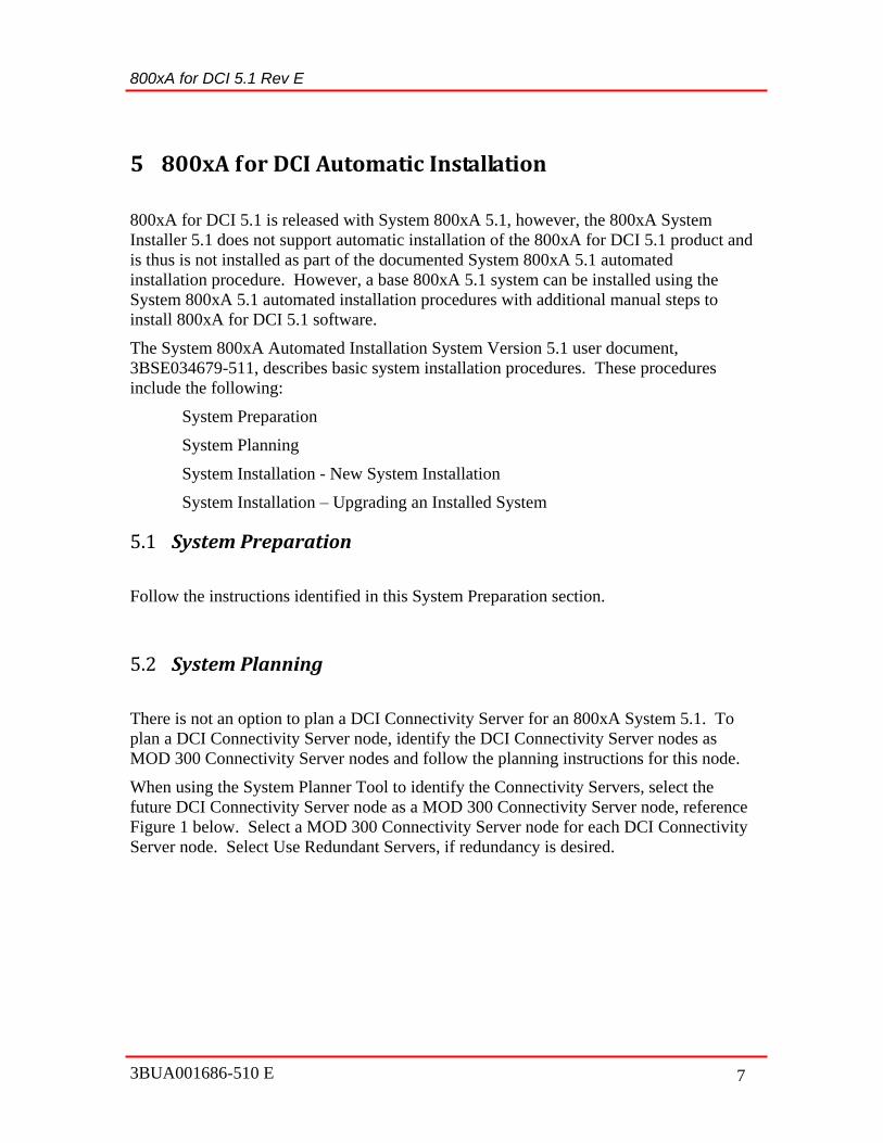
5 800xA for DCI Automatic Installation
800xA for DCI 5.1 is released with System 800xA 5.1, however, the 800xA System
Installer 5.1 does not support automatic installation of the 800xA for DCI 5.1 product and
is thus is not installed as part of the documented System 800xA 5.1 automated
installation procedure. However, a base 800xA 5.1 system can be installed using the
System 800xA 5.1 automated installation procedures with additional manual steps to
install 800xA for DCI 5.1 software.
The System 800xA Automated Installation System Version 5.1 user document,
3BSE034679-511, describes basic system installation procedures. These procedures
include the following:
System Preparation
System Planning
System Installation - New System Installation
System Installation – Upgrading an Installed System
5.1 System Preparation
Follow the instructions identified in this System Preparation section.
5.2 System Planning
There is not an option to plan a DCI Connectivity Server for an 800xA System 5.1. To
plan a DCI Connectivity Server node, identify the DCI Connectivity Server nodes as
MOD 300 Connectivity Server nodes and follow the planning instructions for this node.
When using the System Planner Tool to identify the Connectivity Servers, select the
future DCI Connectivity Server node as a MOD 300 Connectivity Server node, reference
Figure 1 below. Select a MOD 300 Connectivity Server node for each DCI Connectivity
Server node. Select Use Redundant Servers, if redundancy is desired.

Figure 1 - Select Product Dialog
5.3 System Installation – New System Integration
Follow the installation steps documented in the System 800xA Automated Installation
System Version 5.1 user document, Section 5, for the following
1. Installation Type
2. Windows Configuration
3. Base System Verification (Installing Third Party Software)
4. 800xA System Installation
At the software installation dialog on the DCI Connectivity Server, deselect
ABB PAS - System Services (MOD) and 800xA for MOD 300 Connect Server
See Figure 2 for an example of the Copy Software Dialog for Connectivity
Server.

800xA for DCI 5.1 Rev E
3BUA001686-510 E 9
Figure 2 – Copy Software Dialog for Connectivity Server
On all other nodes, deselect the 800xA for MOD 300 Connect Client. See Figures
3 and 4 for examples of the Copy Software Dialog for Aspect Servers and Clients.
Figure 3 – Copy Software Dialog for Aspect Server

Figure 4 – Copy Software Dialog for Clients
After the automatic installation of the 800xA 5.1 software components, install
the required 800xA for DCI 5.1 software components on each machine.
A dialog indicating that all System 800xA products have been installed will
appear and prompt for reboot.
After reboot, System Installer will resume at the Configure System step, see
Figure 5 below.

800xA for DCI 5.1 Rev E
3BUA001686-510 E 11
Figure 5 - System Installer Configure System Screen
Cancel, then ESC to temporarily exit System Installer to install 800xA for
DCI 5.1 software manually.
See Appendix A for instructions on installing the 800xA for DCI 5.1 software.
Always install the DCI Connect Extension first. Install the Server feature on
DCI Connectivity Servers only.
If this system is an 800xA Batch Management system, install the DCI Batch
Extension next. Install the Server feature on the DCI Connectivity Servers that
will act as the DCI Batch Management servers.
If using Visual Basic faceplates and graphics, install the DCI VB6 Graphics
Extension last
Click on the Resume Install and Setup icon on the desktop, see Figure 6
below. This will return to the System Installer “Configure System 800xA”
steps.

Figure 6 - Desktop Screen
5. Configuring the 800xA System including Windows Firewall
The Aspect Configuration Wizard progresses through the necessary
configuration steps.
On the DCI Connectivity Server, skip the step to configure the Real-Time
Accelerator Unit Installation and Configuration. On these servers, and, on all
other nodes, skip the configuration steps for the 800xA for Mod 300.
A final step in “Configuring the 800xA System” is to configure the Windows
Firewall. Follow the steps to configure the Windows Firewall for System
800xA 5.1 software. Windows Firewall exceptions for 800xA for DCI 5.1 are
not configured with this tool.
Go to Section 6, 800xA for DCI Post Installation, to execute the 800xA for
DCI post installation steps which include adding 800xA for DCI 5.1 software
exceptions to the Windows Firewall exception list.
6. System Report Generation

800xA for DCI 5.1 Rev E
3BUA001686-510 E 13
5.4 System Installation – Upgrading an Installed System
The supported upgrade paths for System 800xA 5.1 are as follows:
800xA 5.0 SP2 to 800xA 5.1 online
800xA 5.0 SP2 to 800xA 5.1 offline
800xA 4.1 to 800xA 5.1
In general, System Installer 5.1 can be used to automatically upgrade an existing installed
800xA system, systems without 800xA for DCI.
The System 800xA 5.1, System Installer 5.1 cannot be used to automatically upgrade an
existing installed system with 800xA for DCI software. An existing system with 800xA
for DCI software can only be upgraded manually. Follow the instructions in the System
800xA Upgrade System Version 5.1 user document with supplemental steps in this
document for manual upgrade procedures,
In general, upgrading from a System 800xA at a previous system version to System
800xA 5.1 is a matter of performing a Backup/Restore from the old system to the new.
Manually upgrade to the System 800xA 5.1 software, install the 800xA for DCI 5.1
software following the instructions in Appendix A, and then restore the system.
6 800xA for DCI Post Installation
This section documents the post installation procedures for 800xA for DCI.
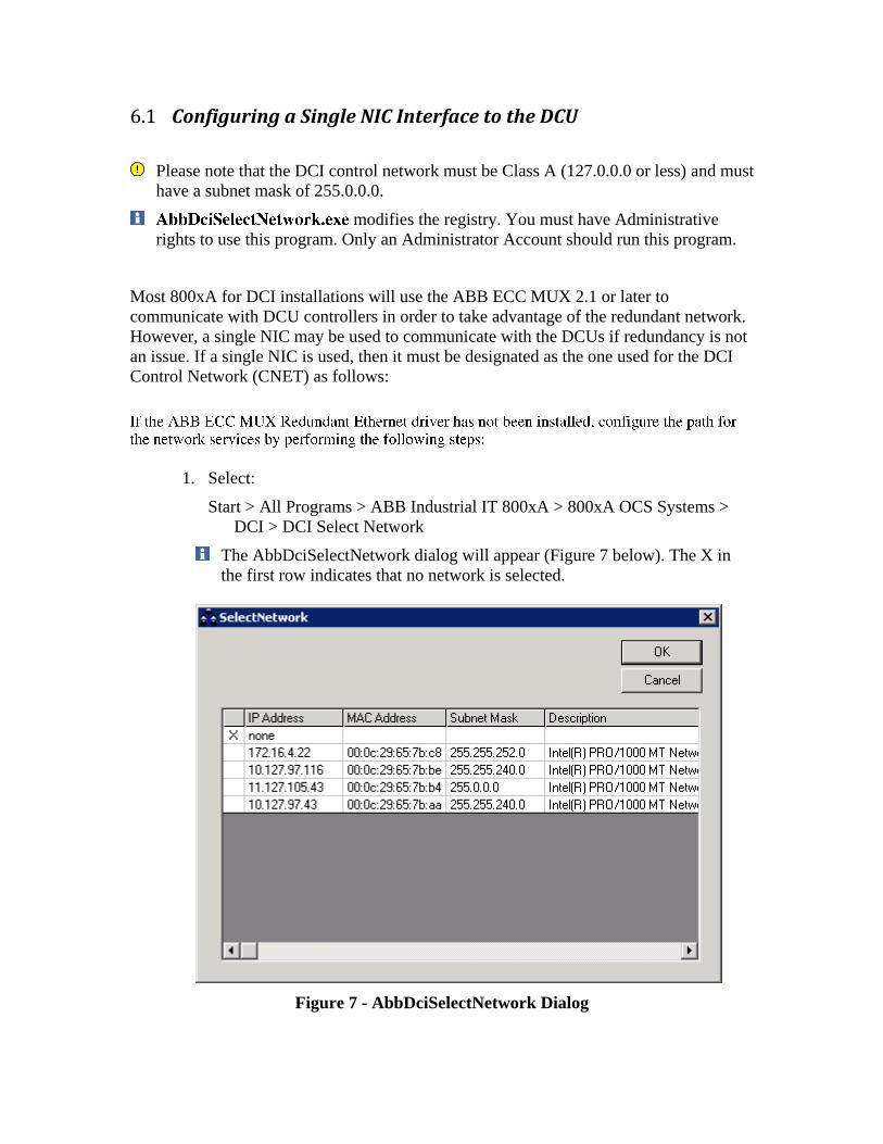
6.1 Configuring a Single NIC Interface to the DCU
Please note that the DCI control network must be Class A (127.0.0.0 or less) and must
have a subnet mask of 255.0.0.0.
modifies the registry. You must have Administrative
rights to use this program. Only an Administrator Account should run this program.
Most 800xA for DCI installations will use the ABB ECC MUX 2.1 or later to
communicate with DCU controllers in order to take advantage of the redundant network.
However, a single NIC may be used to communicate with the DCUs if redundancy is not
an issue. If a single NIC is used, then it must be designated as the one used for the DCI
Control Network (CNET) as follows:
1. Select:
Start > All Programs > ABB Industrial IT 800xA > 800xA OCS Systems >
DCI > DCI Select Network
The AbbDciSelectNetwork dialog will appear (Figure 7 below). The X in
the first row indicates that no network is selected.
Figure 7 - AbbDciSelectNetwork Dialog

800xA for DCI 5.1 Rev E
3BUA001686-510 E 15
2. Choose the network that 800xA for DCI will use by clicking on the row of the
desired network adapter.
Choose the network by IP address. The physical name is provided for help
(description).
3. Click OK. The network is now selected.
4. Reboot the node for the selection to activate.
The next time the network service is run, it will automatically default to the last chosen
network. Repeat Step 1 through Step 3 to choose a new network.
6.2 Creating a DCI OPC Server
Caution: If you are creating a DCI OPC Server for a Batch System, the following
steps must be performed on the individual primary DCI Connectivity Server for
each DCI OPC Server.
Create a Symphony DCI OPC Server object by performing the following steps:
1. Open a Plant Explorer Workplace.
2. Use the Structure Selector to select the Control Structure.
3. Use the Object Browser to navigate to Root of the Control Structure. Right
click and select New Object from the Context Menu. The New Object dialog
appears.
4. Select the Common tab.
5. Expand the following tree:
Object Types > Control System > Symphony DCI
6. Select Symphony DCI OPC Server Network from the Symphony DCI tree.
7. Enter a name for the Symphony DCI OPC Server Network and click Next.
8. The Addition Arguments dialog appears as shown in Figure 8. Click on the
Add button.

Figure 8 - Additional Arguments Dialog
Select the Primary Connectivity Server and Backup Connectivity Server
(if applicable) from the list and click OK.
9. Select ABB.Dci800xADAServer.1 from the Selected OPC Server, ProgID
drop-down list box and click Create.
10. If the DCI Batch system extension has been loaded, the Setup DCI Batch
Service Group dialog will appear.
a. Select Add from the Setup DCI Batch Service Group dialog.
b. Select the Primary Batch Connectivity Server and Backup Batch
Connectivity Server (if applicable) from the list and click OK.
11. Use the DCI Tag Importer to establish all DCI controllers and module tags
under the Symphony DCI OPC Server Network. Refer to 800xA for DCI,
Configuration (3BUA000135-510) for more details.
12. Some DCI system events will be associated with the DCI Node Name of the
Connectivity Server. These events will not be visible unless an Object of the
same name has been configured in the 800xA System. The DCI Node Name is
the name of the DCI node that appears in the CTK DCU Manager. The DCI
Node Name is composed of the Node Number specified at 800xA for DCI

800xA for DCI 5.1 Rev E
3BUA001686-510 E 17
installation prefaced with the string DCI (Example: DCI12). To add the DCI
node object:
a. Right-click on the Symphony DCI OPC Server Network Object.
b. Select New Object from the context menu.
c. Select the Common tab in the New Object dialog.
d. Select Object Types | 3-rd party OPC server support |Generic OPC
Object.
e. Enter the DCI Node Name in the Name edit box.
f. Click Create.
13. Repeat Step 2 through Step 12 for each DCI Connectivity Server
6.3 Configuring the DCI AE Event Collector Structure
The DCU alarm and event stream is collected by each DCI AE Server on each DCI
Connectivity Server node. Every DCI Connectivity Server node collects all alarms and
events presented by all DCU nodes that it communicates with.
Place each DCI Connectivity Server node in an Event Collector Service Group that
covers the same DCU set. The alarms and events are not limited to the set of DCU tag
objects configured for the corresponding DA Server. This means that each AE Server that
communicates with the same DCU set will act as a backup for each other. Configure a
separate Service Provider under a single Service Group for each DCI Connectivity Server
node connected to the same DCU set.
Do not configure separate Service Groups for Connectivity Servers that communicate
with the same DCU set or duplicate alarms will occur.
Do not add a Connectivity Server as a Service Provider on a Service Group that sees a
different DCU set.
Configure the DCI AE Event Collector Structure by performing the following steps:
1. Open a Plant Explorer Workplace.
2. Use the Structure Selector to select the Service Structure.
3. Select the Event Collector, Service object.
4. Select the Configuration tab on the Service Definition aspect.
5. Click Add and the New Service Group Name dialog appears.
6. Enter a name, such as DCI_AE_SGx (where x is a running number), in the
edit box on the New Service Group Name dialog and click OK. The dialog
disappears and the service group name appears in the Groups list.

7. Click Apply in the Service Definition aspect.
8. Expand the Event Collector, Service object and click on the DCI Service
Group object.
9. Select the Configuration tab on the Service Group Definition aspect.
10. Click Add and the New Service Provider Name dialog appears.
11. Enter a name, such as DCI_AE_SP_nodename (where nodename is a DCI
Connectivity Server name), in the edit box on the New Service Provider Name
dialog and click OK. The dialog disappears and the service provider name
appears in the Providers list.
12. Click Apply in the Service Group Definition aspect.
13. Select the DCI Service Provider in the Providers list and click View. The
Service Provider Definition Aspect View appears.
14. Select the desired DCI Connectivity Node from the Node drop-down list box,
click Apply and then close the dialog.
15. Click on the Special Configuration tab on the Service Group Definition
aspect.
16. Select the ABB DCI 800xA OPC Alarm & Event Server from the Alarm
Server drop-down list box.
17. Verify that ABB DCI Alarms & Events appears in the Collection Definition
drop-down list box then click Apply.
18. Verify the connection by clicking on the Status tab on the Service Group
Definition Aspect View and verify that the state is Service.
19. Repeat Step 10 through Step 18 for each DCI Connectivity Server node that is
connected to the same set of DCUs. Do not create a new Service Group for
any of those nodes.
20. Repeat Step 3 through Step 19 for the next set of DCI Connectivity Server
nodes that were not previously configured.
6.4 800xA for DCI Firewall Configuration
On all 800xA for DCI Connectivity Servers, run Windows Firewall Configuration and
use the following procedure to add 800xA for DCI tasks to the Windows Firewall
exception list.
1. Open the Windows Control Panel.
2. Open the Windows Firewall configuration window.
800xA for DCI 5.1 Rev E
3BUA001686-510 E 19
3. In the Windows Firewall window, click on "Allow a program through
Windows Firewall."
4. In the Windows Firewall Settings dialog, select the “Exceptions” tab, if not
already selected.
5. Click on the “Add Programs...” button.
6. In the Add a Program dialog, click on the “Browse...” button.
7. Use the Browse dialog to browse to the location where the DCI Network tasks are
located, usually, "C:\ABB\bin".
8. Click on AbbDciNetRouter.exe in the list of executable objects, and then
click the “Open” button. The Browse dialog disappears.
9. Click on the “OK” button in the Add a program dialog. The Add a program
dialog disappears and the AbbDciNetRouter.exe object appears in the list of
programs in the Windows Firewall Settings programs with the check box
selected.
10. Repeat the "Add a program..." process for tsyncdd.exe, tsyncCtrl.exe, and
tftpd.exe.
11. Click the “Apply” button and then the “OK” button on the Windows Firewall
Settings dialog. The Windows Firewall Settings dialog disappears.
12. Close the Windows Firewall window.
13. Close the Control Panel window.
14. Reboot each 800xA for DCI Connectivity server when the Windows Firewall
configuration is complete.
6.5 800xA for DCI IPSEC Configuration
IPSEC is supported in the release of System 800xA. This functionality is supported
for 800xA for DCI 5.1 RU1 as part of the System 800xA 5.1 release.
Perform the following procedure only on domain controllers.
The use of IPSec in 800xA must be addressed for 800xA for DCI Connectivity Servers
and the HDCU controllers on their control networks. IPSec restricts the node access to
an 800xA system within a domain environment. The restriction extends to all nodes,

including HDCU controllers, thus, IP addresses for all HDCUs must be entered using the
IPSec tool.
DCI redundant controllers are referred to as “a” and “b” units for the right and left DCP.
When running, one of these units will become the online unit and the other will become
the backup unit. Both the “a” and “b” units must have their IP addresses added to the
IPSec rules for exemption.
Follow the instructions on using the ABB 800xA IPSec Configuration Tool. When ready
to proceed with entering the IP addresses of the DCI HDCU controllers, select the “Add
Exemptions for 800xA DCI HDCU Controllers” item in the Exemptions List: combo-box
control.
Add the IP addresses for each HDCU one at a time in the Subnet or IP addresses: text
entry control window and click on the Add Exemptions button to add to the exemptions
list. Add the IP address of both the “a” and “b” units.
6.6 Multiple DCI Batch Servers on a Single DCI Network
Normally when a DCI System Six system is brought forward into 800xA, the usual
method is to declare a separate Service Group for OPC DA functions for each separate
DCI Control Network. For systems that include Batch, this results in separate Service
Groups for DCI Batch OPC DA servers also. This is the correct and only way for DCI
Batch to function in an 800xA environment.
In some instances, for reasons of performance, the process engineer may choose to
declare multiple Service Groups for a single DCI network. They may split the DCUs
between two or more Service Groups so that each Service Group concentrates on their
own set of controllers and is not required to know about the controllers declared for a
different Service Group. When this is done, a single DCI Batch Service Group is created
for the different DCU sets. The result of this is that some of the DCI tag objects fail to be
covered by an In-Service DCI Batch Service Provider.
The following procedure provides a method to combine the DCI Batch OPC DA Service
Providers under the proper DCI Batch OPC DA Service Group.
6.6.1 Procedure
For purposes of illustration, and to make the procedure easier to understand, the
following sample system is defined:

800xA for DCI 5.1 Rev E
3BUA001686-510 E 21
Figure 9 - Sample System Network Drawing
In Figure 9, the two dotted red-line rectangles define the two Service Groups for the
example.
6.6.2 Initial Service Structure
Declaring the two Service Groups results in the OpcDA_Connector Service structure
similar or identical to the following:
- Services
…
- OpcDA_Connector, Service
+ SG_DciSG1, Service Group
+ SG_DciSG2, Service Group
- SG_DCI_Batch_PRIDCICS1, Service Group
- DCI_Batch_Provider_PRIDCICS1, Service Provider
- DCI_Batch_Provider_SECDCICS1, Service Provider
- SG_DCI_Batch_PRIDCICS2, Service Group
- DCI_Batch_Provider_PRIDCICS2, Service Provider
- DCI_Batch_Provider_SECDCICS2, Service Provider
A glance at the four DCI Batch Service Providers shows that one of the providers is in
Service state while the other three are in Initialize state. DCI tag objects that are
serviced by the Service Group that has both Service Providers in Initialize State will not
be able to participate in 800xA Batch.
6.6.3 What has to be Done
PriAS1
Primary
Aspect
Server
SecDciCS2
Secondary
DCI Server 2
PriDciCS2
Primary DCI
Server 2
SecDciCS1
Secondary
DCI Server 1
PriDciCS1
Primary DCI
Server 1
PriBatchS1
Primary
Batch Server
DCU1
DCU2
DCU17
DCU18
Client/Server network
Control
Network
DciSG1 DciSG2

All four Service Providers must be moved to a single Service Group, and both DCI Batch
Data Source Definition Aspects must be changed to point to the remaining Service
Group. Follow the steps in the procedure, substituting the correct names for the Service
Groups and Service Providers you are working with.
6.6.4 Backup the System
An Import/Export file of the Control Structure, the OpcDA_Connector Object and
children in the Service Structure, and the Procedure Structure will be sufficient to return
the system to the present state.
6.6.5 Follow These Steps
1. Back up the system.
2. Go to the Service Structure.
3. Change the name of SG_DCI_Batch_PRIDCICS1 Service Group to
SG_DCI_Batch.
4. Drag and drop both of the Service Providers under SG_DCI_Batch_PRIDCICS2
Service Group Object into the SG_DCI_Batch Service Group Object.
5. In the Service Structure object list, select the OpcDA_Connector Object.
6. Select the Service Definition Aspect.
7. On the Configuration tab in the preview pane, find the Groups: list box.
8. Select the SG_DCI_Batch_PRIDCICS2 Service Group Object and click the
Delete button.
9. Click the Apply button.
10. Go to the Control Structure.
11. Select the DciSG1 Object.
12. Select the DCI Batch Data Source Definition Aspect.
13. In the Service Group drop-down box, select the SG_DCI_Batch Service Group.
14. Click the Apply button, if needed.
15. Select the DciSG2 Object.
16. Select the DCI Batch Data Source Definition Aspect.
17. In the Service Group drop-down box, select the SG_DCI_Batch Service Group.
18. Click the Apply button, if needed.
19. Reboot the DCI Connectivity Server nodes.

800xA for DCI 5.1 Rev E
3BUA001686-510 E 23
7 800xA for DCI Upgrade
The supported upgrade paths for System 800xA 5.1 are as follows:
800xA 5.0 SP2 to 800xA 5.1 online
800xA 5.0 SP2 to 800xA 5.1 offline
800xA 4.1 to 800xA 5.1
Upgrading 800xA 3.1 SP3 to 800xA 5.0 SP2 does not apply for 800xA for DCI.
800xA for DCI was first released with System 800xA 4.1.
All paths assume that the 800xA System has a saved system backup, reference the
System 800xA Maintenance System Version 5.1 user document. All paths require, after
backup and before restore, installing the 800xA System software, and creating the system
as if it were a new installation.
In general, System Installer 5.1 can be used to automatically upgrade an existing installed
800xA system, systems without 800xA for DCI.
The System 800xA 5.1, System Installer 5.1 cannot be used to automatically upgrade an
existing installed system with 800xA for DCI software. An existing system with 800xA
for DCI software can only be upgraded manually. Follow the instructions in the System
800xA Upgrade System Version 5.1 user document with supplemental steps in this
document for manual upgrade procedures,
In general, upgrading from a System 800xA at a previous system version to System
800xA 5.1 is a matter of performing a Backup/Restore from the old system to the new.
Manually upgrade to the System 800xA 5.1 software, install the 800xA for DCI 5.1
software following the instructions in Appendix B, and then restore the system.
7.1 Graphics
It is important to recognize the role that Graphics (Process Graphics or VB Graphics)
plays in the upgrade procedure. (Reference the System 800xA Upgrade System Version
5.1 user document, Section 1 Introduction.)
800xA 5.1 supports Process Graphics 2 as a default with optional VB Graphics
extensions that can be installed and loaded when upgrading.
800xA 5.0 SP2 supported VB Graphics as the default with Process Graphics 2 extensions
that could be installed and loaded.

800xA SV 5.0 SP1 and earlier supported VB Graphics as the default with no option for
Process Graphics 2.
Customers upgrading from previous 800xA versions can still view and modify their VB
Graphics, but they must install their previously licensed version of Visual BASIC 6.0
with SP6 in order to do so. They must also install and load the VB Graphics extensions.
New 800xA 5.1 customers should not install the VB Graphics extensions as they will
only have the VB runtime and will not be able to create and/or modify VB graphics
unless they have a licensed version of Visual BASIC 6.0 with SP6.
7.2 Upgrading 800xA 5.0 SP2 to 800xA 5.1 Online
An online upgrade of 800xA for DCI software can be performed when it is installed with
redundant DCI Connectivity Servers.
800xA for DCI is backed up with the standard 800xA Backup/Restore aspect.
Follow the instructions identified in document 3BSE036342-511 System 800xA Upgrade
System Version 5.1, Section 3 Upgrading 800xA 5.0 SP2 to 800xA 5.1 Online.
Supplement the instructions from Section 3 with 800xA for DCI specific instructions
identified below.
In general, the upgrade flow includes the following procedures:
Pre-Upgrade Procedures
Online Upgrade
Requirements for VB Graphics Extension Software
Post Upgrade Procedures
7.2.1 Pre-Upgrade Procedures
Follow the pre-upgrade procedures identified in Section 3 of the upgrade user document
(3BSE036342-511).
Perform the following procedures to save 800xA for DCI information:
1. Use the import/export utility to export all DCI OPC Server Network
objects and all their children from the Control Structure.
The exported file will be used only if there is a problem with the upgrade.
2. If any modifications/additions were made to Symphony DCI object types
in the Object Type Structure, export only those changes using the
import/export utility.

800xA for DCI 5.1 Rev E
3BUA001686-510 E 25
7.2.2 Online Upgrade
Follow the online upgrade procedures identified in Section 3 of the upgrade user
document (3BSE036342-511).
Once all 800xA base software is loaded, load the 800xA for DCI software using the
procedures in Appendix B. Load them in the following order.
DCI Extension.
DCI Batch Extension (Only if this is a Batch Management System.)
7.2.3 VB Graphics Extension Software
Perform the VG Graphics Extension Software procedures identified in Section 3 of the
upgrade user document (3BSE036342-511) if the restored system makes use of VB
graphics.
Follow the instructions identified in this sub-section. These procedures are applicable to
all 800xA Systems, unless the system that is being upgraded has all Process Graphics 2
graphics and no VB graphics
7.2.4 Loading DCI Software
Once all 800xA base software has been loaded, load the 800xA for DCI software using
the procedures in Appendix B. Load them in the following order.
DCI Extension.
DCI Batch Extension (Only if this is a Batch Management System.)
DCI VB6 Graphics Extension (Only of VB6 graphics is going to be used.)
Execute the Post Installation instructions identified in Section 6 of this document.
7.2.5 Post-Upgrade Procedures
Follow the post-upgrade procedures identified in this section and perform the following
procedure for 800xA for DCI software installation.
7.2.5.1 Maintenance Update of 800xA for DCI
Perform the following procedure on the Primary Aspect Server

–
–
–
8.
-
10.
7.2.5.2 Load ABB DCI VB6 Graphics Extension
If applicable, load the ABB DCI VB6 Graphics Extension using the following procedure.

800xA for DCI 5.1 Rev E
3BUA001686-510 E 27
Perform the following procedure on the Primary Aspect Server
–
5.
7.
Upgrading 800xA 5.0 SP2 to 800xA 5.1 Offline
Follow the instructions identified in document 3BSE036342-511, Section 4 Upgrading
800xA 5.0 SP2 to 800xA 5.1 Offline. You must load the 800xA for DCI extension
software as a manual step after loading all other 800xA software.
7.3.1 System Backup
800xA for DCI is backed up with the standard 800xA Backup/Restore aspect. In
addition, you may want to perform the following backups.
7.3.2 800xA for DCI Specific Backup
Use the following procedure to save 800xA for DCI information:
1. Use the import/export utility to export all DCI OPC Server Network
objects and all their children from the Control Structure.
INFORMATION: The exported file will be used only if there is a problem with the
upgrade.
2. If any modifications/additions were made to Symphony DCI object types
in the Object Type Structure, export only those changes using the
import/export utility.
7.3.3 VB Graphics Extension Software
Follow the instructions identified in this sub-section. These procedures are applicable to
all 800xA Systems, unless the system that is being upgraded has all Process Graphics 2
graphics and no VB graphics
7.3.4 Loading DCI Software
Once all 800xA base software has been installed, Install the 800xA for DCI software
using the procedures in Appendix B. Install them in the following order.
ABB DCI Extension.
ABB DCI Batch Extension (Only if this is a Batch Management System.)
ABB DCI VB6 Graphics Extension (Only of VB6 graphics is going to be used.)
Execute the Post Installation instructions identified in Section 6 of this document.
7.3.5 Post-Upgrade Procedures
Follow the post-upgrade procedures identified in this section and perform the following
procedure for 800xA for DCI software installation
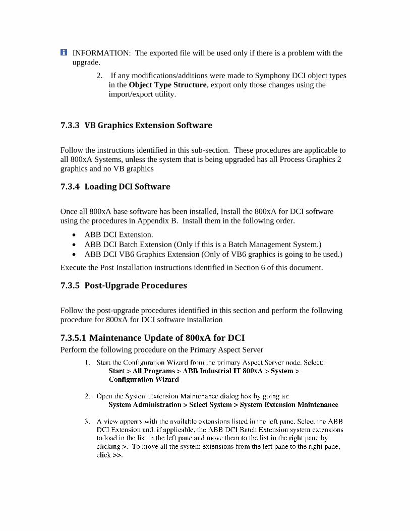
7.3.5.1 Maintenance Update of 800xA for DCI
Perform the following procedure on the Primary Aspect Server

800xA for DCI 5.1 Rev E
3BUA001686-510 E 29
–
–
–
8.
10.
7.3.5.2 Load ABB DCI VB6 Graphics Extension
If applicable, load the ABB DCI VB6 Graphics Extension using the following procedure.
Perform the following procedure on the Primary Aspect Server

–
5.
7.
7.4 Upgrading 800xA 4.1 to 800xA 5.1 Offline
Follow the instructions identified in Section 5 Upgrading 800xA 4.1 to 800xA 5.1
Offline. It is important to realize that the 800xA 4.1 system is configured for VB
graphics. In 800xA 5.1 system, the system is defaulted with Process Graphics. It is
important to load the VB extensions for products in the system or convert the VB
graphics to Process Graphics.
You must upgrade from 4.1 to 5.0 and then to 5.0 SP2 before upgrading to 5.1. Follow
all instructions in the 800xA 5.0 Upgrade Document to upgrade 800xA for DCI to 5.0.
Then follow the instructions in this document to upgrade 800xA for DCI from 5.0 SP2 to
5.1

800xA for DCI 5.1 Rev E
3BUA001686-510 E 31
8 800xA for DCI Maintenance
800xA for DCI is released with 800xA 5.1, however maintenance is not identified in the
documented System 800xA System Maintenance (3BSE046784-510). Basic 800xA 5.1
system maintenance can be performed using the System 800xA System Maintenance
documented procedures with additional manual steps to maintain 800xA for DCI
software.
Document System 800xA System Maintenance (3BSE046784-510) provides instruction
for the following:
System Check - To get full benefit of the system, it needs to be inspected on a regular
basis.
Operation System Update - It is increasingly important to keep the automation systems
current with available security updates. ABB validates security updates from Microsoft
with respect to relevance to and compatibility with System 800xA. By properly
upgrading an automation system installation with security updates, it is possible to avoid
or mitigate damage from attacks by certain types of malicious software.
Node Restart and System Shutdown/Restart- Contains information on the order to start
and stop a node or system.
Import/Export - The Import/Export tool allows you to move applications to and from any
800xA System. The data is saved as objects and aspects in archive files (.afw). The
Import/Export tool allows you to store and restore objects, aspects, and entities. It is
possible to view the contents of an archive file.
Backup and Restore - The backup and restore procedures consists of two different parts;
backup of standard Windows system and backup of the System application data.
Single Node Replacement - This covers the procedures that must be performed in order to
recover from a node failure in a complete 800xA 5.1 System
Engineering Repository - This section provides information on configuring the
Engineering Repository tool.
Information Management - This section provides guidelines and reference information
related to configuring and maintaining Information Management software.
800xA for DCI specific maintenance procedures are identified for Backup and Restore.
8.1 800xA for DCI Backup and Restore
Follow the instructions identified in document 3BSE046784-510, Section 6 Backup and
Restore and perform the following procedures for 800xA for DCI software installation.
Save Function-Specific Information
System 800xA Backup
System 800xA Restore

Recover Function-Specific Information
8.1.1 Save Function-Specific Information
Follow the instructions identified in this section and compliment with the 800xA for DCI
procedures below:
8.1.1.1 800xA for DCI
The following steps should be used to save function-specific information for 800xA for
6.
8.1.2 800xA System Backup
Follow the instructions identified in this section.
8.1.3 800xA System Restore
Follow the instructions identified in this sub-section of document 3BSE046784-510.
8.1.4 Restore Function-Specific Information
Follow the instructions identified in this sub-section of document 3BSE046784-510, and
compliment with the 800xA for DCI procedures below
8.1.4.1 800xA for DCI
The following steps should be used to restore 800xA for DCI:

800xA for DCI 5.1 Rev E
3BUA001686-510 E 33
To perform a FULL restore, click the buttons in the Restore window. To restore only
selected items, click the desired buttons in the Restore window, then select the
desired items from the resulting window. Click to begin the restore operation.
8.2 800xA for DCI Single Node Replacement
Follow the instructions identified in document 3BSE046784-510, Section 7 Single Node
Replacement and perform the following procedures for 800xA for DCI software
installation.
8.2.1 Connectivity Server Replacement for 800xA for DCI
Use the following procedures to restore 800xA 5.1 DCI Connectivity Server and
Composer CTK Engineering Nodes.
Replacing the DCI Connectivity Server requires reloading the system from a saved disk
image. All configuration information is kept in the Windows Registry or on the Aspect
System Server and is restored with that node (or nodes).
To restore a DCI Connectivity Server node:

8.2.2 Composer CTK Engineering Node Replacement
The Composer CTK Engineering node is not an 800xA node but has backup procedures
defined in the 800xA for DCI Configuration instruction that need to be performed
regularly.
5.

800xA for DCI 5.1 Rev E
3BUA001686-510 E 35
Appendix A - Installing 800xA for DCI 5.1 Software
The 800xA for DCI 5.1 software deliverable includes the components identified below:
the DCI Extension, the DCI Batch Extension, and the DCI VB6 Graphics Extension.
Installation Steps for DCI Extension
1. Go to the folder where the 800xA for DCI Extension release software was downloaded or copied.
2. Open the folder named DCI Extension/Media Software.
3. Double click on Setup.exe to start the installation process.
4. Click on the Next button on the installation wizard Welcome page.
5. Click on the “I accept …” radio button and click on Next.
6. You can change the location of where the 800xA for DCI software will be
installed by clicking on the Browse button and selecting a new folder. Click on the OK button when finished.
7. Click on the Next button to accept the destination folder.
8. Select either DCI Client or DCI Server or both (the default) if you are planning to
create an 800xA for DCI Connect Server, and use the client functions on it.
The 800xA for DCI Client feature provides all of the components needed to use
800xA for DCI aspects on 800xA Clients. Install this feature on 800xA Aspect
System Servers and on 800xA Clients where you need to view and use 800xA for
DCI aspects.
The 800xA for DCI Server feature provides all of the components needed to connect
to Harmony DCU controllers from 800xA. Install this feature only on DCI
Connectivity Servers.

9. Click on the Next button.
10. If this is a Connectivity Server, you will need to select a node number and a
console group number. The node number must be unique for each 800xA for DCI Servers, and must be between 1 and 99. The console group number may be from 1 to 50, and may be used to isolate the DCI server from Conductor nodes. Click on the Next button after selecting the node number and console group number.
11. Review the feature selections and click the Back button to change.
12. Click the Next button to start copying software and finish the installation
process.
13. The copy process will take from a few seconds to a minute.
14. When the copy process completes, the aspects and servers will be registered, and the DCI Network Services will be started.
15. Click on the Finish button to acknowledge the completion of the installation
process.
Installation Steps for DCI Batch Extension
1. You must install 800xA for DCI Extension before installing the 800xA Batch for DCI Extension.
2. Go to the folder where the 800xA Batch for DCI Extension release software was
downloaded or copied.
3. Open the folder named DCI Batch Extension/Media Software.
4. Double click on setup.exe to start the installation process.
5. Click on the Next button on the installation wizard Welcome page.
6. Click on the “I accept …” radio button and click on Next.
7. You can change the location of where the 800xA for DCI software will be installed by clicking on the Browse button and selecting a new folder. Click on the OK button when finished.

800xA for DCI 5.1 Rev E
3BUA001686-510 E 37
8. Click on the Next button to accept the destination folder.
9. Select DCI Batch Server if you are planning to create an 800xA Batch for DCI
Connect Server. You may only install the 800xA Batch for DCI Server feature on DCI Connectivity Servers. The DCI Client Support is always selected.
The DCI Batch Support provides an interface from 800xA for DCI to Batch
Management. Install this feature on each 800xA for DCI Client node when 800xA
Batch for DCI is installed on the system.
The DCI Batch Server feature provides the DCI OPC Server for Batch Management.
Install this feature only on DCI Connectivity Servers.
10. Click on the Next button.
11. Review the feature selections and click the Back button to change.
12. Click the Next button to start copying software and finish the installation
process.
13. The copy process will only take a few seconds.
14. When the copy process completes, the aspects and servers will be registered.
15. Click on the Finish button to acknowledge the completion of the installation process.
Installation Steps for DCI VB6 Graphics Extension
1. Go to the folder where the 800xA for DCI VB6 graphics Extension release software was downloaded or copied.
2. You must install the 800xA for DCI Extension before loading the 800xA for DCI
VB6 Graphics Extension.
3. Open the folder named DCI VB6 Graphics Extension/Media Software.
4. Double click on setup.exe to start the installation process.
5. Click on the Next button on the installation wizard Welcome page.
6. Click on the “I accept …” radio button and click on Next.

7. You can change the location of where the 800xA for DCI software will be
installed by clicking on the Browse button and selecting a new folder. Click on the OK button when finished.
8. Click on the Next button to accept the destination folder.
9. Click the Next button to start copying software and finish the installation
process.
10. The copy process will only take a few seconds.
11. When the copy process completes, the aspects and servers will be registered.
12. Click on the Finish button to acknowledge the completion of the installation process

800xA for DCI 5.1 Rev E
3BUA001686-510 E 39
Appendix B – 800xA for DCI Windows Firewall Configuration On all 800xA for DCI Connectivity Servers, run Windows Firewall Configuration and
use the following procedure to add 800xA for DCI tasks to the Windows Firewall
exception list.
1. Open the Windows Control Panel.
2. Open the Windows Firewall configuration window.
3. In the Windows Firewall window, click on "Allow a program through
Windows Firewall."
4. In the Windows Firewall Settings dialog, select the “Exceptions” tab, if not
already selected.
5. Click on the “Add Programs...” button.
6. In the Add a Program dialog, click on the “Browse...” button.
7. Use the Browse dialog to browse to the location where the DCI Network tasks are
located, usually, "C:\ABB\bin".
8. Click on AbbDciNetRouter.exe in the list of executable objects, and then
click the “Open” button. The Browse dialog disappears.
9. Click on the “OK” button in the Add a program dialog. The Add a program
dialog disappears and the AbbDciNetRouter.exe object appears in the list of
programs in the Windows Firewall Settings programs with the check box
selected.
10. Repeat the "Add a program..." process for tsyncdd.exe, tsyncCtrl.exe, and
tftpd.exe.
11. Click the “Apply” button and then the “OK” button on the Windows Firewall
Settings dialog. The Windows Firewall Settings dialog disappears.
12. Close the Windows Firewall window.
13. Close the Control Panel window.
14. Reboot each 800xA for DCI Connectivity server when the Windows Firewall
configuration is complete.

Contact us
Copyright© 2015 ABB.
All rights reserved.
www.abb.com/800xA
www.abb.com/controlsystems
3B
UA
001686
-51
0 E