Embed Size (px)
Citation preview

VL800 Valve Adjustment Procedure
Do not attempt this procedure unless you are mechanically inclined! Background: If valve clearances are too tight, the valves can be seriously damaged by warping or burning and compression will eventually suffer from lack of proper valve seating. Valves are cooled by resting against the valve seat if they're open too long they have insufficient time to rest against their seats and transfer their heat to the cylinder head. On the other hand, if the clearance is too loose, the result will be rough running, loss of power, and excessive wear of the valve train components. Therefore, if you must choose, remember that a little looser is better than tighter. Before you adjust the valves the engine must be dead cold. In other words, the engine must have been left to cool overnight. The cold clearance is .003 -.005 of an inch on all intake valves, and .007 - .009 of an inch on all exhaust valves. I ended up setting them at .004 and .008. However, if you have a bike that tends to overheat, you can set the exhaust to .009. You can also do the opposite; set your intake valves to .005 for better breathing. I hope this helps you get your Volusia running well, it is fairly straightforward once you get a “feel” for the process! -Brian Rusk (BriMan) PS - This is a work in progress. If you see anything that should be changed or have a way to refine it further, PLEASE TELL ME! I want to make the most accurate, easy to use document I can. - BriMan

Procedure: If you have a stand or lift, raise the bike; if not, place a 2X4 block of wood under the side stand to prop it up, but make absolutely sure it is firm to avoid having it fall down. Remove seats and gas tank. Remove the front cylinder right hand chrome head cover and take the spark plug out.

Remove the rear cylinder left hand chrome head cover and also take the spark plug out.

Removal of the spark plugs makes it easier to turn the engine over by hand. You will be working on the rear cylinder valves from the left side of the bike and working on the front cylinder valves from the right side of the bike. On the top front and top rear of each cylinder head are the valve covers (four in total). The exhaust valves are the ones on the “outside” of the engine located near the exhaust pipes. The intake valves are the ones next to the carb on the “inside”.
Remove the valve covers; there are six 8 mm bolts & two 10 mm nuts. Make sure you note exactly where and how each cover is placed, but each cylinder uses two different bolt patterns, so you can’t mix those two up, but make sure to not mix up covers from either cylinder. It’s a good idea to keep a magnetized screwdriver handy to retrieve dropped bolts, since with some of the valve cover bolts there is almost no room to maneuver. I found a box end 8mm wrench came in handy that has a slightly offset head.

It's a cumbersome process and you might have to loosen the radiator to get better access, although I didn’t. The valve covers have rubber O-rings which must be cleaned, and coat the O-rings with a little oil before reinstall, (if the O-rings are flattened or in bad condition, buy new ones). Also, clean the valve covers well and make sure the O-ring is still in correctly, since it fits in a certain manner.

Watch out for the PAIR valve’s chrome tubes blocking access to the intake valve cover on the rear cylinder, you may have to lift it some to get the cover off.

The right exhaust cover is a tight fit to get the inside bolt, but with that offset box end wrench you can get it. Be careful not to strip the bolt head.

On the left engine case cover is a large plug with a hex head slot, remove it with an Allen wrench or socket; be very careful since the plug is chrome and sometimes very tight, therefore you can mess it up real easy. This plug has a rubber O-ring which you must cleaned (replace if damaged); smear a little oil before reinstalling. Under that plug is a nut (17 mm) you use to turn the engine crankshaft counterclockwise.

Just in front of this large plug is a smaller plug on the front side of the left engine cover. Remove the smaller plug with an Allen wrench or socket. This is the sight glass used to align your valve timing marks. There is an alignment arrow (a line) stamped on the case on the left side of the sight glass looking at it from the front.

Turn the crankshaft counterclockwise slowly, watch out, cause the flywheel will suddenly “spin” once you pass a certain point and if you’re turning too fast it will overshoot the RT mark (if you look carefully, the direction arrow is stamped on the flywheel). Also, I turned the engine over a couple of times to take up any slack. Turn the flywheel counterclockwise until you see on the flywheel the RT mark, which is followed closely by an FT mark (RT meaning that the rear cylinder piston is at top dead center and its exhaust and intake valves are either fully closed or open). If for some reason you go past the marks, do not turn back, and just keep on turning counterclockwise until you reach them again. Remember that you might have to go several turns because what you are trying to achieve is place the piston at TDC with the valves in the fully closed position, ie. "relaxed". The RT and FT marks are for adjusting the valves. Adjust the valves at these marks. You will work on the rear cylinder first, so get to the RT mark first. Once the RT mark is in the center of the sight glass and the line on the RT is aligned with the alignment arrow on the sight window, you must check to see if there is free play at both the intake (on the rear part of the cylinder) and exhaust (on the front part of the cylinder) valve rocker arms by jiggling them up and down. The movement is slight. If not, rotate the crankshaft 360 degrees (counterclockwise) and check again until the valves reach the "relaxed" position.
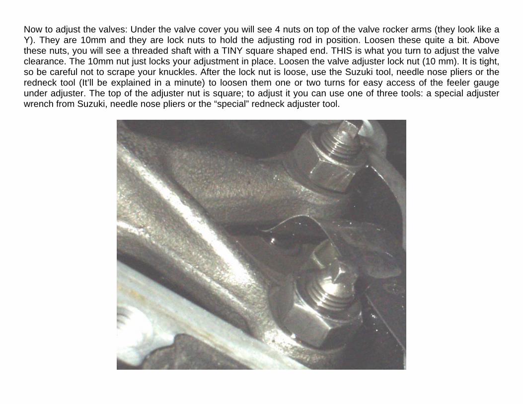
Now to adjust the valves: Under the valve cover you will see 4 nuts on top of the valve rocker arms (they look like a Y). They are 10mm and they are lock nuts to hold the adjusting rod in position. Loosen these quite a bit. Above these nuts, you will see a threaded shaft with a TINY square shaped end. THIS is what you turn to adjust the valve clearance. The 10mm nut just locks your adjustment in place. Loosen the valve adjuster lock nut (10 mm). It is tight, so be careful not to scrape your knuckles. After the lock nut is loose, use the Suzuki tool, needle nose pliers or the redneck tool (It’ll be explained in a minute) to loosen them one or two turns for easy access of the feeler gauge under adjuster. The top of the adjuster nut is square; to adjust it you can use one of three tools: a special adjuster wrench from Suzuki, needle nose pliers or the “special” redneck adjuster tool.

Volusia Guy’s Redneck adj. tool: Take an old credit card and cut a strip approx. 1/2" in width the length of the card with some scissors. Using a razor or wire cutters, cut a notch in the end of the strip that fits the square end of the valve adjuster we mentioned above. This will be your adjusting tool and is strong enough for the job, but it will strip before the adjuster does and allows you a feather-like touch in your adjustments.

Slide your feeler gauge under the valve and leave it there until you are done with the adjustment of that valve. (If you use a flashlight, you'll see where the two parts meet under the adjusting nut) Slide your gauge between these. Tighten the adjuster until you feel it “pinched” and is hard to move, then back the adjuster just a little to allow you to slide the gauge around. You should feel the metal dragging, but not too much.

Close your eyes and feel the slide of the feeler blade to become acquainted with the sensation. If you have a friend who knows how to work a feeler gauge ask him to check it. You should hear and feel a particular rubbing sound as the feeler slides between the metal surfaces. Once you've got it, press the opposite end of the rocker (opposite to where the feeler is) to make sure it's down and you are not getting a false reading (you can also lift the rocker for the same effect). If everything is OK, carefully place a wrench on the adjuster lock nut and on top of that wrench place the special adjuster bolt wrench (or whatever tool you chose) and tighten the lock nut while holding the adjuster bolt to keep it from moving. Tighten partially, recheck the clearance and if it's right, tighten the lock nut all the way. Recheck clearance. Repeat for the remaining exhaust valve and do the same for the intake valves. (VL800’s have four valves per cylinder).
Now turn the crankshaft counterclockwise until you reach the FT mark and repeat the above for the front cylinder. Make sure you go past the RT mark once as the turn will be about 450 degrees. Make sure the valves are in the "relaxed" position.

The biggest hassle when adjusting is being able to slide that straight feeler gauge into a most restricted space, but curving the blade and a few MacGyver style moves should do it. If you have never adjusted valves get ready to spend a good while, some cussin' and adjusting several times 'till you get it down pat. Once you have some practice it's faster and easier.
Install the valve, timing and crankshaft covers. Organize your wiring, straps and "other stuff"; Remember to tighten the spark plugs! Replace the cylinder head chrome covers, tank and seats.
VAVLE SPECIFICATIONS: Intake: .08-.13 mm or .003-.005 in Exhaust: .17-.22 mm or .007-.009 in SOME TIPS: Rather than deal with the "feel" issue, use a .004 gauge for the intakes, and a .008 for the exhaust. This way if you’re a little tight or a little loose, you should still be within spec. Pick the easiest access valve to start with, so you can get a “feel” for the process. Plan for plenty of time! Be prepared to smack your forehead and go “Doh!”, and proceed to redo the process. YOU DO NOT WANT TO RUSH DOING THIS! Plan a work party where you can have some people over who are familiar with gauges, or have done this before to help you in the tight spots. I really wish I’d had someone to look over my shoulder! This How To was compiled by BriMan from information found originally on the IntruderAlert.com website by Fernan Soto, and the VolusiaOwners.com website by VolusiaGuy, Paige, and Several others. Thanks Guys! Without y’all I would have spent a fortune! This is a work in progress. If you see anything that should be changed or have a way to refine it further, PLEASE TELL ME! I want to make the most accurate, easy to use document I can. - BriMan