Embed Size (px)
Citation preview
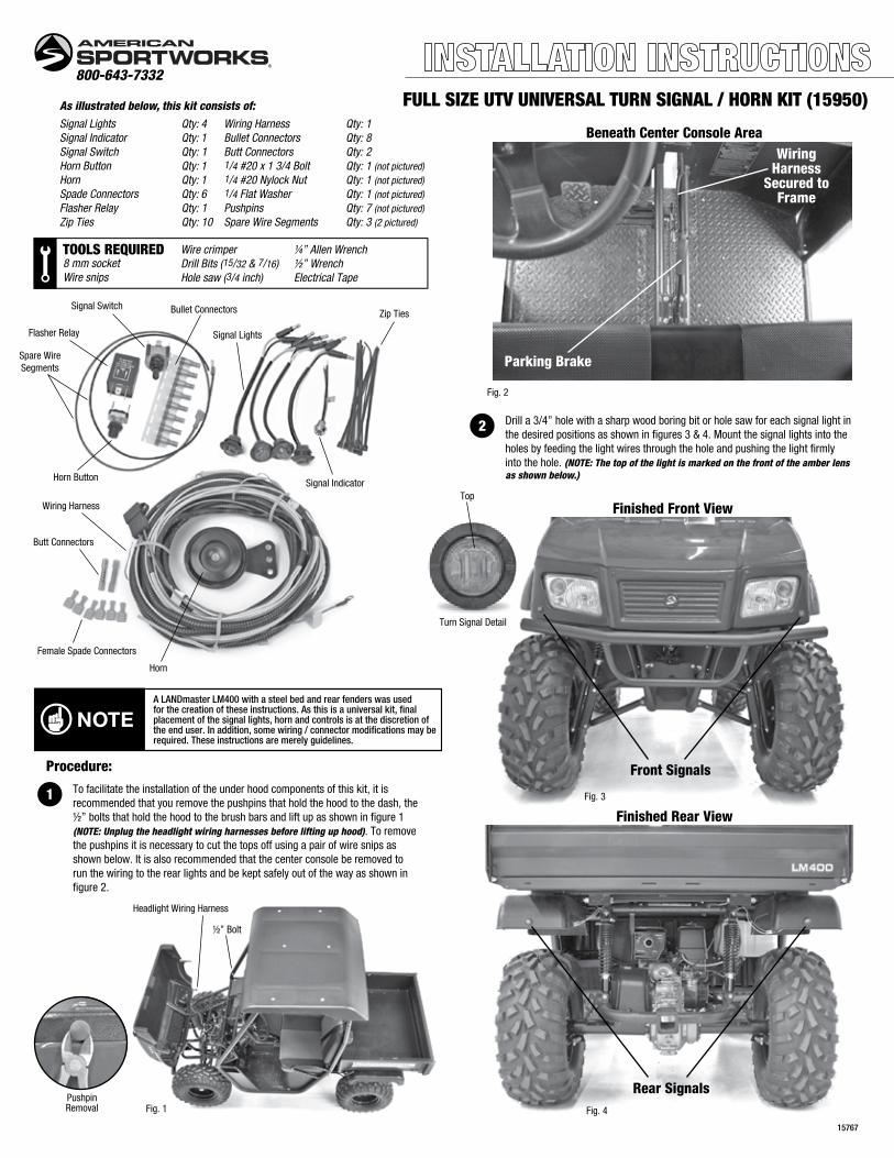
FULL SIZE UTV UNIVERSAL TURN SIGNAL / HORN KIT (15950)
Female Spade Connectors
Turn Signal Detail
800-643-7332
Procedure:
1
15767
As illustrated below, this kit consists of:
Signal Lights Qty: 4Signal Indicator Qty: 1Signal Switch Qty: 1Horn Button Qty: 1Horn Qty: 1Spade Connectors Qty: 6Flasher Relay Qty: 1Zip Ties Qty: 10
Wiring Harness Qty: 1Bullet Connectors Qty: 8Butt Connectors Qty: 21/4 #20 x 1 3/4 Bolt Qty: 1 (not pictured)1/4 #20 Nylock Nut Qty: 1 (not pictured)1/4 Flat Washer Qty: 1 (not pictured)Pushpins Qty: 7 (not pictured)Spare Wire Segments Qty: 3 (2 pictured)
Horn
Horn Button
Bullet Connectors
Signal Lights
Signal Switch
Flasher Relay
Spare WireSegments
Butt Connectors
Signal Indicator
Wiring Harness
Zip Ties
To facilitate the installation of the under hood components of this kit, it is recommended that you remove the pushpins that hold the hood to the dash, the ½” bolts that hold the hood to the brush bars and lift up as shown in figure 1 (NOTE: Unplug the headlight wiring harnesses before lifting up hood). To remove the pushpins it is necessary to cut the tops off using a pair of wire snips as shown below. It is also recommended that the center console be removed to run the wiring to the rear lights and be kept safely out of the way as shown in figure 2.
Fig. 3
Fig. 4
A LANDmaster LM400 with a steel bed and rear fenders was usedfor the creation of these instructions. As this is a universal kit, finalplacement of the signal lights, horn and controls is at the discretion ofthe end user. In addition, some wiring / connector modifications may berequired. These instructions are merely guidelines.
NOTE
Finished Front View
Front Signals
Rear Signals
Finished Rear View
Fig. 1
Headlight Wiring Harness
½” Bolt
PushpinRemoval
Fig. 2
Parking Brake
WiringHarness
Secured toFrame
Beneath Center Console Area
2 Drill a 3/4” hole with a sharp wood boring bit or hole saw for each signal light in the desired positions as shown in figures 3 & 4. Mount the signal lights into the holes by feeding the light wires through the hole and pushing the light firmly into the hole. (NOTE: The top of the light is marked on the front of the amber lens as shown below.)
TOOLS REQUIRED8 mm socketWire snips
Wire crimperDrill Bits (15/32 & 7/16)Hole saw (3/4 inch)
¼” Allen Wrench½” WrenchElectrical Tape
Top

3 See figure 12 on the back page to familiarize yourself with the proper wiring of this kit.
Beginning with the harness under the hood area, feed the rear light harness section (see figure 12) though the dash panel, following the path of the shifter cables, through the cab of the vehicle beneath where the center console was removed and through to the rear of the vehicle. Beginning at the rear signal lights, cut the [ Green, Yellow and White wires ] to the needed length, strip the ends and crimp onto the female bullet connectors. Plug the White harness wires into the White signal light wires. Plug the Green and Yellow harness wires to their appropriate signal lights as shown in figure 5.(NOTE: It is not necessary to secure the wiring harness at this time.)
6 Mount the horn to the frame beneath the hood of the vehicle with the 1/4 #20 bolt, washer and nylock nut provided in the recommended pre-drilled location as shown in figures 8 & 10. It may be necessary to drill a hole in the fame tubing to place the horn in another desired position. NOTE: make sure the Red horn wire from the harness will reach where the horn will be placed. Take the Red and White wires marked “Horn” from the harness and cut to the appropriate length being careful not to cut them too short. Strip the ends of the wires and install female spade terminals onto the ends.
7 Snip off the eyelet ends and use the butt connectors to attach longer wiring to the signal indicator making sure to attach enough wire to reach to the destinations. You may have to snip off the eyelet ends of some other wires and attach the supplied female spade connectors for use with your vehicle. The Black (ground) wire from the signal indicator will need to be connected to the White (ground) wire from the harness using the .25” Female spade terminal end for 18 – 22 gauge wire. Refer to figures 10, 11 & 12 on the next 2 pages for final wiring of the kit.
Secure all wires as needed to the frame using electrical tape or zip ties as shown in figures 6 & 10.
Be careful to avoid moving parts, steering linkage, shift linkage, driveline parts and the exhaust system when securing the harness to the frame. Also be sure that the dump bed can still function properly when the harness is secured.
4 Connect the front signal lights to the other end of the wiring harness in the same way as the rear lights.
5 Locate suitable areas for the horn button, the signal indicator and the turn signal switch in the recommended locations below. Be sure to mount the controls where they will be visible when the vehicle is being driven. Drill two 15/32” holes for the horn button and signal switch and a 7/16” hole for the signal indicator. NOTE: Make sure to use the stainless steel washer when mounting the signal switch on a plastic area. Mount the controls and install the rubber boots as shown in figures 7 & 9.
Fig. 6
Fig. 7
Fig. 8
Fig. 9
Fig. 5
Green / WhiteHarness Wires
Yellow / WhiteHarness Wires
(right) (left)
Front Signal Lights Shown
Placement of Controls
Placement of Horn
Mounting of Controls
Wiring
Rear Signal Lights Shown
Bullet ConnectorsWhite to White (Ground)Green to Black (Right Signal)
Horn ButtonTurn Signal Switch Turn Signal Indicator
Stainless Steel Washer
Turn Signal Switch
Turn Signal IndicatorFlasher Relay
Horn Button
PlasticDash
PlasticDash
Yellow tosignal lights
Green tosignal lights
Grooved nut
Stainless Steel Washer
Rubber Boot
White from“Horn” harness
Black to Horn
Orange from harness
Red to signal indicator
Red toflasherrelay
Red to Flasher Relay
Black (joined with White from“flasher” harness) to Terminal Ground
Grooved nutRubber Boot
PlasticDash
P
FLAS
HE
RFO
RLE
D12V
0.1W~100W
L+
Red from “Flasher” harness
CAUTION
Reattach hood to the brush bars and to the dash using the provided pushpins.

Turn
Sig
nal S
witc
hRe
d, G
reen
& Y
ello
ww
ires
from
har
ness
Sign
al In
dica
tor
Ligh
tCr
imp
spar
e re
d se
gmen
t wire
to re
d in
dica
tor w
ire w
ith b
utt
conn
ecto
r and
con
nect
tofla
sher
rela
y.
Crim
p sp
are
segm
ent (
blac
k or
whi
te) t
o bl
ack
wire
with
butt
conn
ecto
r and
join
with
whi
te g
roun
d w
ire fr
om “
flash
er”
harn
ess.
Con
nect
to n
egat
ive
/gr
ound
sid
e of
term
inal
blo
ck.
Horn
But
ton
Whi
te w
ire fr
om h
arne
ss.
Blac
k w
ire to
hor
n.
Horn
Red
wire
from
har
ness
.Bl
ack
wire
to h
orn
butto
n.
Flas
her
Rela
yRe
d w
ire fr
om h
arne
ss,
red
wire
from
sig
nal
indi
cato
r lig
ht a
ndor
ange
wire
from
har
ness
.
Term
inal
Blo
ckOr
ange
wire
from
har
ness
to p
ositi
ve s
ide.
Whi
te fr
om “
flash
er”
harn
ess
join
ed w
ith g
roun
d fr
om tu
rnsi
gnal
indi
cato
r to
nega
tive
/gr
ound
sid
e.
Sign
al L
ight
sYe
llow
/Whi
te F
rom
har
ness
.Gr
een/
Whi
te fr
om h
arne
ss.
Fina
l Wir
ing
of c
ompo
nent
s
UNDE
R HO
OD A
REA
.25”
Fem
ale
Spad
e Te
rmin
al E
ndfo
r 18
– 2
2 Ga
uge
Wir
eJo
ins
grou
nd w
ire fr
om s
igna
l ind
icat
or li
ght (
blac
kor
whi
te) t
o w
hite
gro
und
wire
from
“fla
sher
” ha
rnes
s.Pl
ugs
into
the
nega
tive
/ gro
und
side
of t
erm
inal
blo
ck.
Fig. 10

Wiring Harness / Control components
Front LightHarness Section
Rear LightHarness Section
GreenRight Turn
Yellow
Brown (not needed)
White
White
Green
Green
Red
Yellow
Yellow
Brown (not needed)
White
White
Terminal BlockFront Right Signal
Signal Indicator
Flasher RelayRear Right Signal
Wiring Diagram
Front Left Signal
Rear Left Signal
W
W
O
WY
G
WY
Signal Switch
Horn Button
Horn
P
L+
G
B
B
R
R
R
+ –
W = whiteB = blackG = greenY = yellowR = redO = orangeNOTE: The brown wire is not used in this kit
amsportworks.com
Signal Light
Black (positive)
White (ground)
}
Left Turn}
Right Turn
To turn signal switch
{
{Left Turn{
Red
Red(to horn)
Orange/Brown(brown not needed)
To flasher relay{White(connected with ground from turn signal indicatorand plugged into negative terminal block)
White(to horn button)
Flasher
Orange(to positive terminal block)
Hor
nFu
se
12 V
olt
Horn
Black (to horn button)Red (from harness)
+
Horn Button
Black (to horn)
White (from harness)
Turn Signal Switch
Yellow (from harness)
Red (from harness)
Green (from harness)
Flasher Relay
Orange/Brown (from harness)
Red (to signal indicator)
Red (from “flasher” harness)
+P
L
Turn Signal IndicatorRed(to flasher relay)
Black(with either black or white sparesegment joined with White from“flasher” harness and plugged intonegative terminal block)
Fig. 11
Fig. 12