Embed Size (px)
Citation preview
Refrigerated Warehouses – Introduction Page 8-1
2008 Nonresidential Compliance Manual August 2009
8 Refrigerated Warehouses
8.1 Introduction This section of the nonresidential compliance manual addresses refrigerated warehouses. Since regulation of refrigerated warehouses is new for the 2008 Standards (§126), a separate section covering the majority of the refrigerated warehouse requirements has been provided. The Standards described in this section of the manual address refrigerated space insulation levels, under slab heating in freezers, evaporator fan controls, compressor part load efficiency in specific applications, condenser sizing, condenser fan power and condenser fan controls. Other sections of the manual address interior lighting power (Chapter 5), cool roofs (Section 3.4), and outdoor lighting power (Chapter 6), which may be installed in conjunction with refrigerated warehouses.
8.1.1 Organization and Content
This section of the manual focuses on Standards provisions unique to refrigerated warehouses. All buildings regulated under Part 6 of Title 24 must also comply with the General Provisions of the Standards (§100 – §102, §110 – §111) and additions and alterations requirements (§149). These topics are generally addressed in Sections 1 and 2 of the manual and in the Reference Appendices.
This chapter is organized as follows:
• Section 8.1 Introduction
• Section 8.2 Building Envelope requirements
• Section 8.3 Mechanical Systems requirements
• Section 8.4 Additions and Alterations
8.1.2 Mandatory Measures and Compliance Approaches
The energy efficiency requirements for refrigerated warehouses are all mandatory. There are no prescriptive requirements or performance compliance paths for refrigerated warehouses. Since the provisions are all mandatory, there are no trade-offs allowed between the various requirements. The application must demonstrate compliance with each of the mandatory measures. Exceptions to each mandatory requirement where provided are described in each of the mandatory measure sections below.
8.1.3 Scope and Application
§126
§126 of the Standards addresses the energy efficiency of refrigerated spaces within buildings, including both coolers and freezers. Coolers are defined as refrigerated spaces cooled between 32°F (0°C) and 55°F (13°C). Freezers are

Page 8-2 Refrigerated Warehouses – Introduction
2008 Nonresidential Compliance Manual August 2009
defined as refrigerated spaces cooled below 32°F (0°C). The Building Energy Efficiency Standards do not address walk-in refrigerators and freezers, as these are covered by the Appliance Efficiency Regulations (Title 20). A walk-in refrigerator or freezer is defined as a refrigerated space less than 3,000 ft² in floor area.
Additionally, areas within refrigerated warehouses designed solely for the purpose of quick chilling or quick freezing of products are exempt from the Standards. Quick chilling and freezing spaces are defined as spaces with a design refrigeration evaporator capacity of greater than 240 Btu/hr-ft² of floor space, which is equivalent to 2 tons per 100ft² of floor space, at conditions prevailing during system operation (applied conditions).
The intent of the Standards is to regulate storage space, not quick chilling space or process equipment. Recognizing that there is often a variety of space types and equipment connected to a particular suction group in a refrigerated warehouse, it is not always possible to identify compressor plant equipment that serve the storage space only. It would be outside the intent of the Standards to apply the compressor plant requirements to an industrial process that is not covered by the Standards, while a small storage space is also attached to the suction group. Similarly, it would be outside of the intent of the Standards to exclude a compressor plant connected to a suction group serving a large storage space covered by the Standards on the basis of a small process cooler or quick chill space also connected to the same suction group. For the purposes of compliance with the Standards, the compressor plant requirements apply when 80 percent or more of the design load connected to the suction group is to serve storage space(s). A suction group refers to one or more compressors that are connected to one or more refrigeration loads, that all operate at a common suction pressure.
A variety of space types and processes may be served by a compressor plant at different suction temperatures. When all of these compressors share a common condenser loop, it is impossible to address only the equipment serving the long-term storage spaces. For purposes of compliance with the Standards, the provisions addressing condensers apply when the total design load of all long-term storage spaces served by compressors using a common condenser loop is greater than or equal to 80 percent of the total design load.
Example 8-1
Question A space within a refrigerated warehouse is used for quick chilling of product during a portion of the season, and long term storage for the remainder of the season. The design evaporator capacity is 300 Btu/hr- ft² at the applied conditions. Is this space required to meet the Standards?
Answer Yes. While the design evaporator capacity exceeds 240 Btu/hr- ft², this space is not used solely for quick chilling and therefore must comply.

Refrigerated Warehouses – Building Envelope Page 8-3
2008 Nonresidential Compliance Manual August 2009
Example 8-2
Question A new compressor plant serves both storage and quick chilling space. The design capacity of the storage space is 500 tons. The design capacity of the quick chilling space is 50 tons. Is the compressor plant required to meet the requirements of the Standards?
Answer Yes. Since more than 80 percent of the design capacity of the system is serving storage space, the compressor plant requirements apply.
8.2 Building Envelope This part of the refrigerated warehouse section [§126(a) and §126(b)] addresses mandatory requirements for refrigerated space insulation R-value and under slab heating.
8.2.1 Opaque Envelope Insulation
§126(a)
The minimum R-values of insulation applied to the enclosing surfaces of cold storage and frozen storage spaces are shown in Table 8-1.
Manufacturers must certify that insulating materials comply with California Quality Standards for Insulating Materials (CCR, Title 24, Part 12, Chapters 12-13), which ensure that insulation sold or installed in the state performs according to stated R-values and meets minimum quality, health, and safety standards. Builders may not install insulating materials, unless the product has been certified by the Department of Consumer Affairs, Bureau of Home Furnishing and Thermal Insulation. Builders and enforcement agencies shall use the Department of Consumer Affairs Directory of Certified Insulation Material to verify the certification of the insulating material.
Table 8-1 – Refrigerated Warehouse Insulation Values
SPACE SURFACE MNIMUM R-VALUE (°F⋅hr⋅ft²/Btu) Frozen Storage Roof/Ceiling R-36
Wall R-36 Floor R-36
Cold Storage Roof/Ceiling R-28 Wall R-28
The R-values shown in Table 8-1 apply to all surfaces enclosing a refrigerated space, including refrigerated spaces adjoining conditioned spaces, other refrigerated spaces, unconditioned buffer spaces and the outdoors. The R-values are the nominal insulation R-values and do not include the R-value of other building materials or internal or external “film” resistances. The R-values shown in Table 8-1 are independent of the thermal mass of the enclosing surface.

Page 8-4 Refrigerated Warehouses – Mechanical Systems
2008 Nonresidential Compliance Manual August 2009
Example 8-3
Question A refrigerated warehouse designed to store produce at 45°F (7°C) is constructed from tilt-up concrete walls and concrete roof sections. What is the minimum R-value of the wall and roof insulation?
Answer Since the storage temperature is between 32°F (0°C) and 55°F (13°C), the space is defined as cold storage. The minimum R-value of the wall and roof insulation according to Table 8-1 is R-28.
Example 8-4
Question A refrigerated warehouse is constructed of a wall section consisting of 4 inches of concrete, 6 inches of medium density (2 lb/ft³) foam insulation and another 4 inches of concrete. The nominal R-value of the foam insulation is R-5.8 per inch. What is the R-value of this wall section for code compliance purposes?
Answer The insulating value of the concrete walls is ignored. The R-value of this wall section for code compliance purposes is based on the 6 inches of foam insulation at R-5.8 per inch, or R-34.8.
8.2.2 Underfloor Heating
§126(b)
Underfloor heating systems should be used under frozen storage warehouses to prevent soil freezing and expansion. Underfloor heating can be electric resistance, forced air, or heated fluid; however, underfloor heating systems utilizing electric resistance heating elements are not permitted unless they are thermostatically-controlled and disabled during the summer on-peak period. The summer on-peak period is defined by the supplying electric utility, but generally occurs from 12 PM to 6 PM weekdays during the months of May through October. The control system used to control any electric resistance underfloor heating elements must turn the elements off during this period. The control system used to control electric resistance underfloor heating elements must be shown on the building drawings and the control sequence demonstrating compliance with this requirement must be documented on the drawings and in the control system specifications.
8.3 Mechanical Systems
8.3.1 Overview
This section addresses mandatory requirements for mechanical systems serving refrigerated spaces. Mechanical system components addressed by the Standards

Refrigerated Warehouses – Mechanical Systems Page 8-5
2008 Nonresidential Compliance Manual August 2009
include evaporators (air units), compressors, condensers, and refrigeration system controls. The requirements for each of these components are described in the following sections.
The requirements apply to all system and component types with the exception of the specific exclusions noted in §126. The following figures identify some of the common system and component configurations that fall under §126.
Figure 8-1 is a schematic of a single stage system with direct expansion (DX) evaporator coils. Figure 8-2 identifies a single stage system with flooded evaporator coils, while Figure 8-3 shows a single stage system with pump recirculated evaporators. Figure 8-4 is a schematic of a typical two-stage system with an intercooler between the compressor stages.
COMPRESSORS
LIQUID RECEIVER
EXPANSION VALVE
EVAPORATIVECONDENSER
EVAPORATOR
Figure 8-1 – Single Stage System with DX Evaporator Coil

Page 8-6 Refrigerated Warehouses – Mechanical Systems
2008 Nonresidential Compliance Manual August 2009
EVAPORATIVECONDENSER
LIQUID RECEIVER
SURGE TANK
EVAPORATOR
FEED VALVE
GR
AVI
TY F
EED
COMPRESSORS
Figure 8-2 – Single Stage System with Flooded Evaporator Coil

Refrigerated Warehouses – Mechanical Systems Page 8-7
2008 Nonresidential Compliance Manual August 2009
EVAPORATIVECONDENSER
LIQUID RECEIVER
SURGE TANK
EVAPORATOR
FEED VALVE
COMPRESSORS
EVAPORATOR
PUMP
Figure 8-3 – Single Stage System with Pump Recirculated Evaporator Coils

Page 8-8 Refrigerated Warehouses – Mechanical Systems
2008 Nonresidential Compliance Manual August 2009
EVAPORATIVECONDENSER
LIQUID RECEIVER
INTERCOOLER
FEED VALVE
SURGE TANK
EVAPORATOR
FEED VALVE
HIGH-STAGECOMPRESSORS
LOW-STAGECOMPRESSORS
Figure 8-4 – Two-Stage System with Flooded Evaporator Coil
8.3.2 Evaporators
§126(c)
Fan powered evaporators used in coolers and freezers have limits on the fan motor type for small fan motors and requirements for fan speed control. Single phase fan motors less than 1 hp operated at less than 460 volts must be electronically commutated. This requirement is designed to reduce fan power in small evaporator fans, and is consistent with the requirements of the Appliance Efficiency Regulations. Documentation must be submitted to the code enforcement authority that documents the use of electronically commutated motors in the fan powered evaporators containing single phase fan motors smaller than 1 hp.
In addition to the requirement for electronically commutated motors in small evaporator fans, the speed of all evaporator fans must be controlled in response to space conditions using a continuously variable control method. Two-speed control is not an acceptable method. Units are generally controlled based on local space temperature, but other conditions, such as relative humidity, uniformity of air flow, and product temperature may also apply. Maintaining product quality should always be the first consideration. In most cases, variable frequency drives are used to control the speed of evaporator fan motors: although controllers designed to vary the speed of electronically commutated motors may be used to control these types of motors.

Refrigerated Warehouses – Mechanical Systems Page 8-9
2008 Nonresidential Compliance Manual August 2009
The fan speed must be controlled according to space conditions. A common strategy for controlling fan speed is to use a controller that measures the difference between the space temperature and the space temperature set point, and sends a control signal proportional to the temperature difference. A variable frequency drive is used to reduce fan speed as the space temperature set point is met. There is no requirement for minimum speed (how much the speed of the fan is reduced when the room is at set point temperature), although variable speed control of air unit fans has been successfully used with minimum speeds of 80 percent or lower on direct expansion coils and 70 percent or lower on flooded or recirculated coils. The minimum fan speed setting is up to the discretion of the system designer and operator, but the capability to reduce the fan speed in response to space conditions must be provided. The fan speed may be adjusted to maintain adequate air circulation in order to insure product integrity and safety.
For refrigerated spaces that are not solely for quick-chilling or quick-freezing of product (i.e. used for cold storage part of the year), variable speed control must be implemented when the spaces are not performing quick-cooling.
The intent of this requirement is to take advantage of the “third-power” fan law. Due to the physics of the “Fan Laws,” the required fan motor power reduces approximately by the cube of the fan speed, while the airflow is proportional to the fan speed. As a result, running a fan at 80 percent speed requires roughly 55 percent power while providing nearly 80 percent air flow, allowing for a significant percentage of the maximum fan air flow for a fraction of the required power. The figure below shows the correlation between fan speed and both required fan power and approximate airflow.
0%
10%
20%
30%
40%
50%
60%
70%
80%
90%
100%
0% 10% 20% 30% 40% 50% 60% 70% 80% 90% 100%
% Fan Speed and % Air Flow
% F
ull L
oad
Fan
Pow
er
Fan Power
ApproximateAir Flow
Figure 8-5 – Relationship between Fan Speed and Required Power
Correct operation of fan speed control requires the associated system suction pressure to be controlled such that the design capacity of the evaporator is

Page 8-10 Refrigerated Warehouses – Mechanical Systems
2008 Nonresidential Compliance Manual August 2009
maintained. If the suction pressure set point is too high relative to the desired room temperature, the evaporator fans will run at 100 percent speed and energy savings will not be realized. System controls should be provided to maintain suction pressure at design conditions and if floating suction pressure control is utilized, suction pressure should float up only after fan speed is at minimum and should float back down prior to increasing fan speed.
Varying the speed of the evaporator fans, rather than continuous full-speed operation coupled with on/off liquid control, allows the cooling capacity to vary to match the load. This can cause operational problems in systems where the compressor cannot reduce capacity in response to the reduced evaporator load. This situation is common in small air-cooled unitary systems utilizing a single compressor. As a result Evaporators served by a single compressor without unloading capability are not required to have variable speed control. Single compressors less then 50hp often do not have offloading capability. [Exception to §126(c)2].
Example 8-5
Question A split system with a packaged air-cooled condensing unit utilizing a single 30 hp compressor serves two direct expansion coils in a 3,200 ft² cooler. Are the evaporator fans required to have variable speed control?
Answer No. Since the system has a single compressor less than 50 hp, the evaporator fans are exempt from the variable speed requirement.

Refrigerated Warehouses – Mechanical Systems Page 8-11
2008 Nonresidential Compliance Manual August 2009
Example 8-6
Question
A split system with a packaged air-cooled condensing unit, utilizing two reciprocating 40 hp compressors connected in parallel, serves multiple direct expansion coils in a 10,000 ft² cooler. Are the evaporator fans required to have variable speed control?
MINIMUM FAN SPEED: 80%
MINIMUM FAN SPEED: 80%
Answer Yes. Since the evaporators are served by more than one compressor, they must have variable speed control. In order to facilitate the implementation of variable speed control of the evaporator fans, the compressors should have the ability to vary capacity to maintain a stable suction pressure. Since the evaporators are direct expansion coils, the controls should include a minimum fan speed of approximately 80 percent or less.
Example 8-7
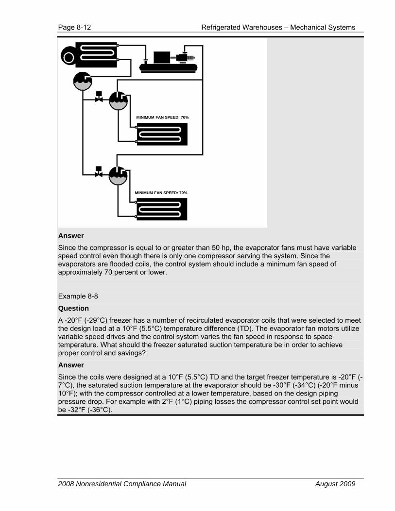
Question A freezer uses a number of flooded evaporator coils with two 1hp fan motors each that are served by a single 75 hp screw compressor. Do the evaporator fans need to have variable speed control?
Page 8-12 Refrigerated Warehouses – Mechanical Systems
2008 Nonresidential Compliance Manual August 2009
MINIMUM FAN SPEED: 70%
MINIMUM FAN SPEED: 70%
Answer Since the compressor is equal to or greater than 50 hp, the evaporator fans must have variable speed control even though there is only one compressor serving the system. Since the evaporators are flooded coils, the control system should include a minimum fan speed of approximately 70 percent or lower.
Example 8-8
Question A -20°F (-29°C) freezer has a number of recirculated evaporator coils that were selected to meet the design load at a 10°F (5.5°C) temperature difference (TD). The evaporator fan motors utilize variable speed drives and the control system varies the fan speed in response to space temperature. What should the freezer saturated suction temperature be in order to achieve proper control and savings?
Answer Since the coils were designed at a 10°F (5.5°C) TD and the target freezer temperature is -20°F (-7°C), the saturated suction temperature at the evaporator should be -30°F (-34°C) (-20°F minus 10°F); with the compressor controlled at a lower temperature, based on the design piping pressure drop. For example with 2°F (1°C) piping losses the compressor control set point would be -32°F (-36°C).

Refrigerated Warehouses – Mechanical Systems Page 8-13
2008 Nonresidential Compliance Manual July 2010
8.3.3 Condensers
§126(d)
The most common refrigerants in use today are either single component or azeotrope refrigerants. An azeotrope is a blend of different components that together form a mixture with its own unique set of thermodynamic properties. A good example of an azeotrope would be a mixture of salt and water; both single component and azeotrope refrigerants boil and condense at the same temperature for a given pressure
Other refrigerant types called zeotropes are blends of several components that do not combine and form a mixture. In this case the individual components retain their own thermodynamic properties. A good example of a zeotrope is a blend of oil and water. For zeotropic refrigerants at a given pressure, the saturated vapor temperature (dew point) is not the same as the saturated liquid temperature (bubble point). The difference in these two temperatures is called temperature glide. PT chart information published by manufacturers for blends with temperature glide greater than about 5 degrees F generally list both the bubble-point and the dew point pressure at a given temperature.
Saturated Condensing Temperature (SCT). For single component and azeotrope refrigerants, SCT is the saturation temperature corresponding to the refrigerant pressure at the condenser entrance. For zeotropic refrigerants, the SCT is the arithmetic average of the dew point and bubble point temperatures corresponding to the refrigerant pressure at the condenser entrance.
All refrigeration systems using ammonia as the refrigerant must be evaporatively cooled. This requirement may be met by an evaporative condenser or by use of a water-cooled condenser connected to a closed loop fluid cooler or cooling tower. Air cooled condensers and groundwater condensers are not permitted in ammonia systems. The condensers (whether evaporative condensers or water-cooled condenser plus cooling tower/fluid cooler) must be sized to provide sufficient heat rejection capacity under design conditions while maintaining a specified maximum “approach” temperature that varies by climate. When determining design heat rejection rates, reserve or backup compressors are not included in the total heat rejection calculations. The approach temperature is defined as the difference between the saturated condensing temperature and the outdoor wet-bulb temperature. Designers should use the 0.5 percent design wet-bulb temperature from Table 2-3 – Design Day Data for California Cities in the Reference Joint Appendices JA2 to demonstrate compliance with this requirement. The approach temperature requirements are listed in Table 8-2.
Table 8-2Condenser fans for evaporative condensers must be continuously variable speed. Variable frequency drives are commonly used to provide continuously variable speed control of condenser fans. The condensing temperature control system must be designed to control all fans serving a common condenser loop in unison. Thus, the fan speed of all fans within a single condenser or set of condensers serving a common high side or cooling water loop should modulate together, rather than running some fans at full flow while controlling the condensing temperature by varying the speed of a single fan. Once the fan speed has been reduced to a minimum level, fans may be shut down while modulating the speed of the remaining fans to maintain the condensing temperature set point.
The minimum saturated condensing temperature set point for systems utilizing evaporative condensers must be 70°F (21°C) or less. To provide stable system operation at the minimum condensing temperature, all components in the system must be capable of operating at a saturated condensing temperature less than or equal to the minimum saturated condensing temperature set point.
To minimize overall system energy consumption, the condensing temperature set point in evaporatively cooled systems must be reset using outdoor wet bulb temperature (i.e. variable set point control) rather than controlling to a single set point.
Alternative set point control strategies may be utilized which achieve similar results to the prescribed wet bulb following control method; controlling fan speed by utilizing calculations or mapped performance to minimizing total compressor and condenser fan power. These controls are uncommon but may be used if the control method is sufficiently described and proven to the satisfaction of the local enforcement agency.

Page 8-14 Refrigerated Warehouses – Mechanical Systems
2008 Nonresidential Compliance Manual August 2009
Table 8-2 – Approach Temperature Requirements for Evaporative Condensers 0.5% Design wet-bulb temperature from Table 2-3 Maximum Approach Temperature
≤ 76°F (24°C) 20°F (11°C)
Between 76°F (24°C) and 78°F (26°C) 19°F (10.5°C)
≥ 78°F (26°C) 18°F (10°C)
Example 8-9
Question The refrigerated warehouse compressor plant shown below has a backup or “swing” compressor. Does the heat rejection from this compressor need to be included in the condenser sizing calculations?
Answer No. The heat rejection calculations for purposes of this Standards exclude compressor(s) that are used solely for backup. In this case, the calculations would include the heat of rejection from Compressors 2, 3, and 4 and would exclude Compressor 1.
Example 8-10
Question A system is to be designed with an evaporative condenser in a location where the 0.5 percent design wet bulb temperature is 72°F (22°C). What is the maximum design approach?

Refrigerated Warehouses – Mechanical Systems Page 8-15
2008 Nonresidential Compliance Manual August 2009
Answer Since the 0.5 percent design wet-bulb temperature is less than 76°F (24°C), the maximum design approach per Table 8-2 is 20°F (11°C). The design condensing temperature would be 92°F (33.3°C) (72°F plus 20°F).
Example 8-11
Question A refrigerated warehouse with evaporative condensers is being commissioned. The control system designer has utilized a wet bulb-following control strategy to reset the system saturated condensing temperature (SCT) set point. The refrigeration engineer has calculated that adding a TD of 15°F (8.3°C) above the ambient wet bulb temperature should provide a saturated condensing temperature set point that minimizes the combined compressor and condenser fan power usage throughout the year. What might the system SCT and SCT set point trends look like over an example day?
Answer The following figure illustrates what the actual saturated condensing temperature and SCT set points could be over an example day using the wet bulb-following control strategy with a 15°F (8.3°C) TD and also observing the 70°F (21°C) minimum condensing temperature requirement. As the figure shows, the SCT set point is continuously reset 15°F (8.3°C) above the ambient wet bulb temperature until the minimum SCT set point of 70°F is reached. The figure also shows a maximum SCT set point (in this example, 90°F (32.2°C) which may be utilized to limit the maximum control set point, regardless of the ambient temperature value or TD parameter.
0
10
20
30
40
50
60
70
80
90
100
12:00 AM 3:00 AM 6:00 AM 9:00 AM 12:00 PM 3:00 PM 6:00 PM 9:00 PM 12:00 AMTime of Day
Tem
pera
ture
[°F]
Wet Bulb Temperature
SCT Setpoint
15°F Control TD
70°F Minimum SCT Setpoint
90°F Maximum SCT Setpoint
Actual SCT

Page 8-16 Refrigerated Warehouses – Mechanical Systems
2008 Nonresidential Compliance Manual August 2009
Air-cooled condensers are permitted in systems using refrigerants other than ammonia. The condensers must be sized to provide sufficient heat rejection capacity under design conditions while maintaining a specified maximum “approach” temperature that varies according to the temperature of the refrigerated spaces served by the system. The approach temperature is defined as the difference between the saturated condensing temperature and the outdoor dry-bulb temperature. When determining design heat rejection rates for the purpose of determining minimum condenser capacity in this Standards, reserve or backup compressors are not included in the total heat rejection calculations.
Designers should use the 0.5 percent design dry-bulb temperature from Table 2-3 – Design Day Data for California Cities in the Reference Joint Appendices JA2 to demonstrate compliance with this requirement. The approach temperature requirements are shown in Table 8-3.
Table 8-3 – Approach Temperature Requirements for Air-Cooled Condensers
Refrigerated Space Type Space temperature Maximum Approach Temperature Cooler ≥ 32°F (0°C) 15°F (8.3°C)
Freezer < 32°F (0°C) 10°F (5.6°C)
One and two compressor unitary condensing units designed and rated as a single piece of equipment, with compressor(s) totaling less than 100 hp and with individual compressor systems of less than 50 hp are exempt from the approach temperature requirements.
To improve efficiency of small fractional horsepower motors commonly used in air-cooled condensers and to maintain consistency with the Appliance Efficiency Regulations, all single phase condenser fan motors less than 1 hp and less than 460 V must be either permanent split capacitor or electronically commutated motors. Documentation must be submitted to the code enforcement authority that documents the use of electronically commutated motors in the condenser fans.
Condenser fans for air-cooled condensers must be continuously variable speed. Variable frequency drives are commonly used to provide continuously variable speed control of condenser fans although controllers designed to vary the speed of electronically commutated motors may be used to control these types of motors. The condensing temperature control system must be designed to control all fans serving a common condenser loop in unison. Thus, the fan speed of all fans within a single condenser or set of condensers serving a common high-side should modulate together, rather than running some fans at full flow while controlling the condensing temperature by varying the speed of a single fan. Once the fan speed has been reduced to a minimum level, fans may be shut down while modulating the speed of the remaining fans to maintain the condensing temperature set point.
The minimum saturated condensing temperature set point for systems utilizing air-cooled condensers must be 70°F (21°C) or less. To provide stable system operation at the minimum condensing temperature, all components in the system must be capable of operating at a saturated condensing temperature less than or equal to the minimum condensing temperature set point.
To minimize overall system energy consumption, the condensing temperature set point in air cooled systems must be reset using outdoor dry bulb temperature (i.e.

Refrigerated Warehouses – Mechanical Systems Page 8-17
2008 Nonresidential Compliance Manual August 2009
variable set point control) rather than controlling to a single set point or staging fans with fixed pressure or ambient set points.
Alternative set point control strategies may be utilized which achieve similar results to the dry bulb following control method; controlling fan speed by utilizing calculations or mapped performance to minimizing total compressor and condenser fan power.
Example 8-12
Question An air-cooled condenser is being sized for a system that has half of its installed capacity serving cooler space and the other half serving freezer space. What is the design approach to be added to the design dry bulb temperature?
Answer Using Table 8-3, condensers for coolers have a design approach of 15°F (8.3°C) and for freezers a design approach of 10°F (5.6°C). When a system serves both freezer and cooler spaces, a weighted average should be used based on the installed capacity. To calculate the weighted average, multiply the percent of the total installed capacity dedicated to coolers by 15°F (8.3°C). Next, multiply the percent of the total installed capacity dedicated to freezers by 10°F (5.6°C). The sum of the two results is the design condensing temperature approach. In this example, the installed capacity is evenly split between freezer and cooler space. As a result, the design approach for the air-cooled condenser is 12.5°F (6.9°C) ([50%*15]+[50%*10] = 7.5 + 5 = 12.5).
Example 8-13
Question A cold storage facility with an air-cooled condenser is being commissioned. The control system designer has utilized a dry bulb following control strategy to reset the system saturated condensing temperature (SCT) set point. The refrigeration engineer has calculated that adding a TD of 11°F (6.1°C) above the ambient dry bulb temperature should provide a saturated condensing temperature set point that minimizes the combined compressor and condenser fan power usage throughout the year. What might the system SCT and SCT set point trends look like over an example day?
Answer The following figure illustrates the actual saturated condensing temperature and SCT set points over an example day using the dry bulb-following control strategy with a 11°F (6.1°C) TD and also observing the 70°F (21°C) minimum condensing temperature requirement. As the figure shows, the SCT set point is continuously reset 11°F (6.1°C) above the ambient dry bulb temperature until the minimum SCT set point of 70°F (21°C) is reached. The figure also shows a maximum SCT set point (in this example, 90°F (32.2°C) which may be utilized to limit the maximum control set point, regardless of the ambient temperature value or TD parameter.

Page 8-18 Refrigerated Warehouses – Mechanical Systems
2008 Nonresidential Compliance Manual August 2009
0
10
20
30
40
50
60
70
80
90
100
12:00 AM 3:00 AM 6:00 AM 9:00 AM 12:00 PM 3:00 PM 6:00 PM 9:00 PM 12:00 AM
Time of Day
Tem
pera
ture
[°F]
Dry Bulb Temperature
SCT Setpoint
70°F Minimum SCT Setpoint 11°F Control TD
90°F Maximum SCT Setpoint
Actual SCT
8.3.4 Compressors
§126(e)
To provide stable operation in compliance with the condensing temperature controls described above, compressors and all associated components (oil cooling systems, oil separators.) must be designed to operate at a minimum condensing temperature of 70°F (21°C) or less. Note, oil separator sizing is often governed by the combination of the minimum condensing temperature and the maximum suction temperature. Suction temperatures above the design value may occur under floating suction temperature control schemes.
Since cooling load generally varies through the day and through the year, compressor system design should address part load efficiency through the use of efficient unloading devices, variable frequency drives on compressor motors, or multiple compressors assigned to a particular suction group.
Screw compressors applied to refrigerated warehouses shall incorporate the capability to automatically vary the volume ratio (i.e. variable Vi) in order to optimize efficiency at off-design operating conditions.
Part Load Efficiency Part load efficiency is especially important when a suction group is served by a single compressor. Single screw compressors greater than 50 hp serving a single suction group must utilize a variable speed drive as the primary means of capacity control, or provide documentation that demonstrates the part load efficiency of the compressor is such that the compressor consumes 60 percent of rated power at

Refrigerated Warehouses – Mechanical Systems Page 8-19
2008 Nonresidential Compliance Manual August 2009
50 percent load. Single compressor systems include systems served by backup or swing compressors.
When there is a single dedicated screw compressor greater than 50 hp serving a suction group, and a variable speed drive is installed on the compressor – the presence of the variable speed drive is the only documentation needed. If a variable speed drive is not used for this application, then a manufacturer's certification of tested part load and full load results for this model of compressor must be provided.
The manufacturer's certification requires the following publicly available data:
• Physical test results of the proposed compressor model at full-rated refrigeration load and at 50 percent of full load.
• This physical test must be conducted with no liquid subcooling and 10°F (5.5°C) superheat for both the full load and 50 percent load conditions.
• The condensing temperature must be identical for both full load and 50 percent load tests.
• Raw data from physical tests and calculations that show that the input power to the compressor at 50 percent of load does not exceed 60 percent of full load power.
• This data must be submitted to the California Energy Commission and must be kept on file by the manufacturer.
Example 8-14
Question Data supplied by the manufacturer of an ammonia screw compressor shows the following performance characteristics:
Percent ofFull Load (%)
Capacity(TR)
Power(BHP)
PerformanceFactor (TR/BHP)
100% 378.2 894.1 0.42390% 340.4 841 0.40580% 302.5 788.4 0.38470% 264.7 736.8 0.35960% 226.9 687 0.33050% 189.1 639.7 0.29640% 151.3 595.4 0.25430% 113.5 555 0.20520% 75.6 519 0.14610% 46 494.3 0.093
Does this compressor meet the part load efficiency criterion specified in §126(e) to be exempt from the requirement to use variable speed control?

Page 8-20 Refrigerated Warehouses – Mechanical Systems
2008 Nonresidential Compliance Manual August 2009
Answer No. The ratio of the brake horse power (BHP) at 50 percent of full load to full load is 639.7/894.1 = 0.72. Since the ratio is greater than 0.60, the compressor must utilize variable speed control.
Example 8-15
Question The system shown below has three 200 hp compressors serving three different suction levels and one 200 hp backup or swing compressor that can be valved into any of the three suction lines. Does this count as having more than one compressor per suction group and exempt the compressors from the requirements in §126(e)2?
EVAPORATIVECONDENSER
LIQUID RECEIVER
COMPRESSOR #4
COMPRESSOR #3
COMPRESSOR #2
COMPRESSOR #1(SWING)
ICE CREAMFREEZER
FREEZERS
COOLERS
SHUT-OFF VALVES
Answer No. The exemption to §126(e)2 only applies when a suction group has two or more dedicated compressors. A compressor that is used solely as backup does not count as a dedicated compressor. As a result, compressors 2, 3, and 4 in the example above must comply with §126(e)2 and use variable speed control unless the ratio of the BHP at 50 percent of full load to full load is less than 0.60.

Refrigerated Warehouses – Additions and Alterations Page 8-21
2008 Nonresidential Compliance Manual August 2009
8.4 Additions and Alterations §149
Requirements related to additions and alterations are covered by the Standards in §149. Definitions relevant to refrigerated warehouses include:
1. An addition is a change to an existing refrigerated warehouse that increases refrigerated floor area and volume. See §149(a)1.
2. When an unconditioned or conditioned building; or unconditioned or conditioned part of a building adds refrigeration equipment so that it becomes refrigerated, this area is treated as an addition.
3. An alteration is a change to an existing building that is not an addition or repair. An alteration could include installing new evaporators, a new lighting system, or a change to the building envelope, such as adding insulation. See §149(b)1.
4. A repair is the reconstruction or renewal of any part of an existing building or equipment for the purpose of its maintenance. For example, a repair could include the replacement of an existing evaporator or condenser. See §149(c).
When refrigeration is provided for an alteration or addition by expanding an existing system, that existing system need not comply with the mandatory measures for refrigerated warehouses. However, any addition or altered space must meet all applicable mandatory requirements. Repairs must not increase the preexisting energy consumption of the repaired component, system, or equipment; otherwise, it is considered to be an alteration.
Example 8-16
Question The new construction is an addition to an existing refrigerated warehouse. The new space is served by an existing refrigeration plant. Does the refrigeration plant need to be updated to meet the Standards?
Answer No. The new construction must comply with the Standards; however, the existing refrigeration equipment is exempt from the Standards.
Example 8-17
Question The new construction includes an addition to refrigerated space and expansion of the existing refrigeration plant. Is the existing refrigeration equipment subject to the Standards requirements?
Answer No. Only the new equipment installed in the added refrigerated space is subject to the requirements of the Standards. If the equipment added to the existing plant is served

Page 8-22 Refrigerated Warehouses – Additions and Alterations
2008 Nonresidential Compliance Manual August 2009
by a separate high side condenser loop, then the new compressors and condensers must comply with the Standards. If the new equipment shares the same high side condenser loop, then it does not need to comply with the Standards.
Example 8-18
Question An upgrade to an existing refrigerated storage space includes replacing all of the existing evaporators with new evaporators. Do the new evaporators need to comply with the Standards?
Answer Yes. A complete renovation of the evaporators in the space is considered to be an alteration. The alteration requirements apply when all of the evaporators in the space are changed.
Example 8-19
Question An existing refrigerated storage space is adding additional evaporators to meet an increase in the refrigeration load. Do the new evaporators need to comply with the Standards?
Answer No. The alteration requirements apply only when all of the evaporators in the space are changed.
Example 8-20
Question An existing evaporator is being replaced by a new evaporator as part of system maintenance. Does the new evaporator need to comply with the Standards?
Answer No. Replacement of an evaporator during system maintenance is considered a repair. However, the energy consumption of the new evaporator must not exceed that of the equipment it replaced.

Refrigerated Warehouses – Compliance Documentation Page 8-23
2008 Nonresidential Compliance Manual August 2009
8.5 Compliance Documentation
Field Inspection Energy Checklist
New for the compliance forms is the Field Inspection Energy Checklist now combined with ENV-1C, LTG-1C, MECH-1C and RWH-1C. The Checklist is designed to help Field Inspectors look at specific features that are critical to envelope compliance and is submitted as part of the Energy Documentation that accompanies the plans. Field inspector checkboxes are incorporated directly into the ENV-1C as part of the Opaque Surfaces, Fenestration Surface Details and Roofing Product sections of the form.
Under the Prescriptive Approach, the Documentation Author is responsible for completing the Field Inspection Energy Checklist. For the Performance Approach this Checklist will automatically be completed by the approved computer program.
A copy shall be made available to the Field Inspector so that during different stage inspection. This is where the Field Inspector will verify whether or not the energy features installed in the field match the values listed in the ENV-1C, LTG-1C, MECH-1C and RWH-1C.
As an example, the Field Inspection Energy Checklist portion is designed to help Field Inspectors look at specifics features that are critical to envelope compliance. These features should match the building plans as indicated on the ENV-1C. If they do, then feature “Passes” – if they don’t, then it “Fails.”
The Field Inspector must verify after the installation of each measure (e.g. Opaque Surface, Fenestration Surface Details and Roofing Products). The Field Inspector in addition must collect a signed ENV-INST (Installation Certificate) from the installer.
In the case if the Field Inspection Energy Checklist does not match exactly the building plans or the ENV-INST form, the field inspector must verify the features are meeting the minimum efficiency or better and if so no further compliance is required from the Architect or responsible party. In the case the features fails to meet the efficiencies (worse), the enforcement agency shall require resubmittal of the actual energy compliance documentation to reflect the actual installed features.
RWH-1C Refrigerated Warehouses (Page 1 of 3)
New for the compliance forms is the Field Inspection Energy Checklist now combined with RWH-1C. The Checklist is designed to help Field Inspectors look at specific features that are critical to envelope compliance and is submitted as part of the Energy Documentation that accompanies the plans. Field inspector checkboxes are incorporated directly into the RWH-1C as part of the Insulation Details in this section of the form.
Under the Prescriptive Approach, the Documentation Author is responsible for completing the Field Inspection Energy Checklist. For the Performance Approach this Checklist will automatically be completed by the approved computer program.

Page 8-24 Refrigerated Warehouses – Compliance Documentation
2008 Nonresidential Compliance Manual August 2009
A copy shall be made available to the Field Inspector so that during different stage inspection. This is where the Field Inspector will verify whether or not the energy features installed in the field match the values listed in the RWH-1C.
The Field Inspection Energy Checklist portion is designed to help Field Inspectors look at specifics features that are critical to refrigerated warehouse compliance. These features should match the building plans as indicated on the RWH-1C. If they do, then feature “Passes” – if they don’t, then it “Fails.”
The Field Inspector must verify after the installation of each measure Insulation Details. The Field Inspector in addition must collect a signed ENV-INST (Installation Certificate) from the installer.
In the case if the Field Inspection Energy Checklist does not match exactly the building plans or the ENV-INST form, the field inspector must verify the features are meeting the minimum efficiency or better and if so no further compliance is required from the Architect or responsible party. In the case the features fails to meet the efficiencies (worse), the enforcement agency shall require resubmittal of the actual energy compliance documentation to reflect the actual installed features.
Certificate of Compliance RWH - 1C is the primary form for Refrigerated Warehouses, which provides compliance information for the use of the enforcement agency’s field inspectors. This form must be included on the plans, usually near the front of the assembly drawings. A copy of these forms should also be submitted to the enforcement agency along with the rest of the compliance submittal at the time of building permit application. With enforcement agency approval, the applicant may use alternative formats of these forms (rather than the Energy Commission’s forms), provided the information is the same and in similar format.
Project Description PROJECT NAME is the title of the project, as shown on the plans and known to the enforcement agency.
CLIMATE ZONE is the California Climate zone in which the project is located. See Reference Joint Appendix JA2 for a listing of climate zones.
CONDITIONED FLOOR AREA has a specific meaning under the Standards. The number entered here should match the floor area entered on the other forms.
PROJECT ADDRESS is the address of the project as shown on the plans and known to the enforcement agency.
DATE is the last revision date of the plans. If the plans are revised after this date, it may be necessary to re-submit the compliance documentation to reflect the altered design. Note that it is the enforcement agency‘s discretion whether or not to require new compliance documentation.
General Information BUILDING TYPE is specified because there are different requirements for Refrigerated Warehouses less than 3,000 square feet and Refrigerated Warehouses 3,000 square feet and larger.
AREAS WITHIN REGRIGERATED WAREHOUSES, the checkboxes are used to determine if the project contains areas within the warehouse designated for quick

Refrigerated Warehouses – Compliance Documentation Page 8-25
2008 Nonresidential Compliance Manual August 2009
chilling or freezing. If the project in deed contains areas designated for quick chilling or freezing with a design cooling capacity greater than 240 Btu/hr-ft2, then that particular space need not comply.
PHASE OF CONSTRUCTION indicates the status of the building project described in the compliance documents. Refer to Section 1.6 for detailed discussion of the various choices.
NEW CONSTRUCTION should be checked for all new buildings, newly conditioned space or for new construction in existing buildings (tenant improvements, see Section 1.7.10.) that are submitted for envelope compliance.
ADDITION should be checked for an addition which is not treated as a stand-alone building, but which uses option 2 described in Section 1.7.12. Tenant improvements that increase conditioned floor area and volume are additions.
ALTERATION should be checked for alterations to an existing building mechanical systems (see Section 1.7.12). Tenant improvements are usually alterations.
Documentation Author’s Declaration Statement The CERTIFICATE of COMPLIANCE is signed by both the Documentation Author and the Principal Refrigerated Warehouse Designer who is responsible for preparation of the plans of building. This latter person is also responsible for the energy compliance documentation, even if the actual work is delegated to a different person acting as Documentation Author. It is necessary that the compliance documentation be consistent with the plans.
DOCUMENTATION AUTHOR is the person who prepared the energy compliance documentation and who signs the Declaration Statement. The person’s telephone number is given to facilitate response to any questions that arise. A Documentation Author may have additional certifications such as an Energy Analyst or a Certified Energy Plans Examiner certification number. Enter number in the EA# or CEPE# box.
Principle Refrigerated Warehouse Designer’ Declaration Statement The Declaration Statement is signed by the person responsible for preparation of the plans for the building and the documentation author. This principal designer is also responsible for the energy compliance documentation, even if the actual work is delegated to someone else (the Documentation Author as described above). It is necessary that the compliance documentation be consistent with the plans. The Business and Professions Code governs who is qualified to prepare plans and therefore to sign this statement. See Section 2.2.2 Permit Application for applicable text from the Business and Professions Code.
Mandatory Measures Note Block The person with overall responsibility must ensure that the Mandatory Measures that apply to the project are listed on the plans. The format of the list is left to the discretion of the Principal Designer.

Page 8-26 Refrigerated Warehouses – Compliance Documentation
2008 Nonresidential Compliance Manual August 2009
RWH-1C (Page 2 of 3) Envelope Requirements
Insulation Details/ Field Inspectors Checklist PAGE NUMBER ON PLANS is for referencing purposes and is the actual page of the plans where the assembly is detailed.
SPACE indicates the area type, either cold storage (≥32oF) or frozen storage (<32oF).
ASSEMBLY TYPE indicates whether the assembly is a wall, roof, ceiling or floor.
INSTALLED INSULATION R-VALUE is the actual installed amount of insulation as shown on the referenced assembly drawings of the plans.
MINIMUM REQUIRED INSULATION R-VALUE is the minimum amount of insulation specified in Table 126-A of the Standards.
ASSEMBLY COMPLIANCE is determined by comparing the installed R-value versus the minimum required R-value and should be indicated in the Pass/Fail checkboxes provided.
RWH-1C (Page 3 of 3) Refrigeration System Requirements
Mandatory Measures The rows following the section, Evaporator, Compressor, Condenser, Evaporative Condenser and Air-Cooled Condenser, should be completed as applicable to the project. The space provided to the right of each device description should be used to indicate the page reference where the device is specified on the plans or schedule.