Embed Size (px)
Citation preview
8 I
4
ANALYSIS OF CORE SAMPLE FROM JET GROUTED SOIL
M. L. ALLAN AND L. E. KUKACKA
OCTOBER 1995
Prepared for: . Sandia National Laboratories Albuquerque, New Mexico
Energy Efficiency and Conservation Division
DEPARTMENT OF APPLIED SCIENCE Y
BROOKHAVEN N A T I O N A L LABORATORY UPTON, LONG ISLAND, NEW YORK 11973
DISCUIMER
This r e p o r t was prepared as an account of work sponsored by an agency of t he United S t a t e s Government. Neither the United S t a t e s Government nor any agency the reo f , nor any of t h e i r employees, nor any of t h e i r con t r ac to r s , sub- con t r ac to r s , o r t h e i r employees makes any warranty, express o r implied, o r assumes any l e g a l l i a b i l i t y or r e s p o n s i b i l i t y f o r the accuracy, completeness, o r usefu lness of any information, appara tus , product o r process d i sc losed , or r ep resen t s t h a t i t s use would not i n f r i n g e p r i v a t e l y owned r i g h t s . Reference he re in t o any s p e c i f i c commercial product, process , o r s e rv i ce by t r a d e n a m e , trademark, manufacturer, o r otherwise, does not necessa r i ly c o n s t i t u t e o r imply i t s endorsement, recommendation, o r favoring by the United S t a t e s Government o r any agency thereof . The views and opinions of au thors expressed he re in do no t necessa r i ly state o r r e f l e c t those of the United S t a t e s Govern- ment o r any agency, cont rac tor , o r subcontractor thereof .
ANALYSIS OF CORE SAMPLES FROM JET GROUTED SOIL
M. L. ALLAN AND L. E. KUKACKA
OCTOBER 1995
Prepared for: Sandia National Laboratories
Albuquerque, New Mexico Document No. AP-8304
Under U. S. Department of Energy Contract No. DEAC02-76CH00016
Brookhaven National Laboratory Upton, New York 11973
2
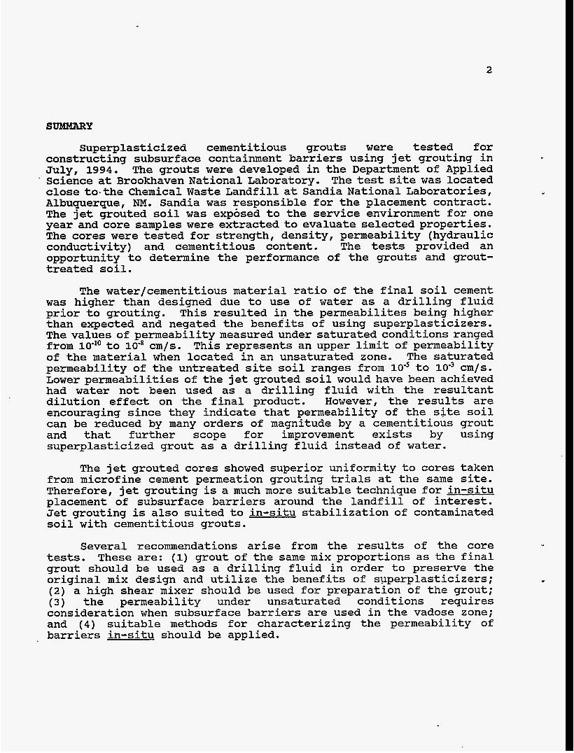
SUMMARY
Superplasticized cementitious grouts were tested for constructing subsurface containment barriers using jet grouting in July, 1994. The grouts were developed in the Department of Applied Science at Brookhaven National Laboratory. The test site was located close to-the Chemical Waste Landfill at Sandia National Laboratories, Albuquerque, NM. Sandia was responsible for the placement contract. The jet grouted soil was expbsed to the service environment for one year and core samples were extracted to evaluate selected properties. The cores were tested for strength, density, permeability (hydraulic conductivity) and cementitious content. The tests provided an opportunity to determine the performance of the grouts and grout- treated soil.
1
The water/cementitious material ratio of the final soil cement was higher than designed due to use of water as a drilling fluid prior to grouting. This resulted in the permeabilites being higher than expected and negated the benefits of using superplasticizers. The values of permeability measured under saturated conditions ranged from lo-’’ to lo-* cm/s. This represents an upper limit of permeability of the material when located in an unsaturated zone. The saturated permeability of the untreated site soil ranges from l o 5 to lo” cm/s. Lower permeabilities of the jet grouted soil would have been achieved had water not been used as a drilling fluid with the resultant dilution effect on the final product. However, the results are encouraging since they indicate that permeability of the site soil can be reduced by many orders of magnitude by a cementitious grout and that further scope for improvement exists by using superplasticized grout as a drilling fluid instead of water.
The jet grouted cores showed superior uniformity to cores taken from microfine cement permeation grouting trials at the same site. Therefore, jet grouting is a much more suitable technique for in-situ placement of subsurface barriers around the landfill of interest. Jet grouting is also suited to in-situ stabilization of contaminated soil with cementitious grouts.
Several recommendations arise from the results of the core tests. These are: (1) grout of the same mix proportions as the final grout should be used as a drilling fluid in order to preserve the original mix design and utilize the benefits of superplasticizers; (2) a high shear mixer should be used for preparation of the grout; (3) the permeability under unsaturated conditions requires consideration when subsurface barriers are used in the vadose zone; and (4 ) suitable methods for characterizing the permeability of barriers in-situ should be applied.
3
INTRODUCTION
Jet grouting field trials were conducted at Sandia National Laboratories, Albuquerque, in July, 1994. The Department of Applied Science (DAS) at Brookhaven National Laboratory (BNL) was involved in the development of some of the cementitious grouting materials tested at the field trial. This involvement was through TTP No. CH 321101, KIn-Situ Stabilization and Containment of Buried Wastell. The Principal Investigators from BNL were Lawrence Kukacka and Marita Allan.
The purpose of the DAS/BNL component of field trial was to specify superplasticized cementitious grouts for in-situ subsurface containment barriers placed using jet grouting. The objective of jet grouting for the application of interest was to form an intimate mix of soil and grout which would exhibit low permeability (hydraulic conductivity) and prolonged durability once cured. The material produced by mixing soil and grout will be termed I1soil cementt1 throughout this report.
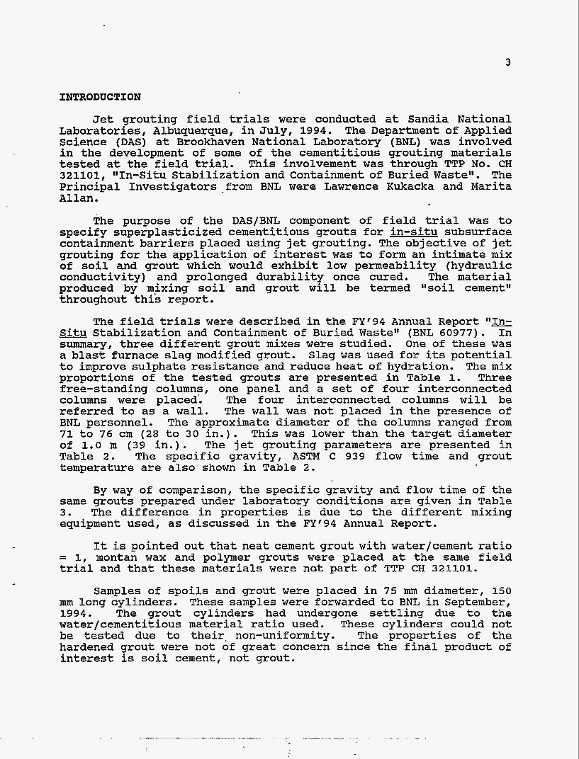
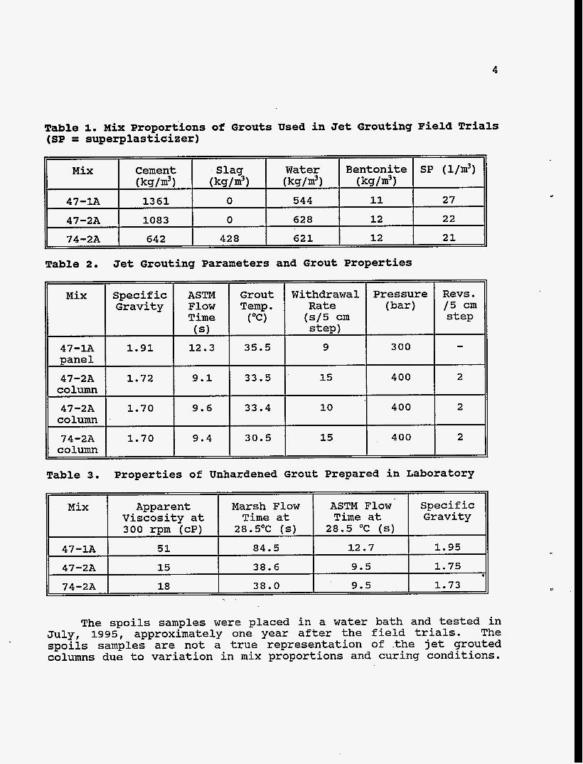
The field trials were described in the FY'94 Annual Report Situ Stabilization and Containment of Buried Wastell (BNL 60977). In summary, three different grout mixes were studied. One of these was a blast furnace slag modified grout. Slag was used for its potential to improve sulphate resistance and reduce heat of hydration. The mix proportions of the tested grouts are presented in Table 1. Three free-standing columns, one panel and a set of four interconnected columns were placed'. The four interconnected columns will be referred to as a wall. The wall was not placed in the presence of BNL personnel. The approximate diameter of the columns ranged from 71 to 76 cm (28 to 30 in.). This was lower than the target diameter of 1.0 m (39 in.). The jet grouting parameters are presented in Table 2. The specific gravity, ASTM C 939 flow time and grout temperature are also shown in Table 2.
By way of comparison, the specific gravity and flow time of the same grouts prepared under laboratory conditions are given in Table 3. The difference in properties is due to the different mixing equipment used, as discussed in the FY'94 Annual Report.
It is pointed out that neat cement grout with water/cement ratio = 1, montan wax and polymer grouts were placed at the same field trial and that these materials were not part of TTP CH 321101.
Samples of spoils and grout were placed in 75 mm diameter, 150 mm long cylinders. These samples were forwarded to BNL in September, 1994. The grout cylinders had undergone settling due to the water/cementitious material ratio used. These cylinders could not be tested due to their. non-uniformity. The properties of the hardened grout were not of great concern since the final product of interest is soil cement, not grout.
4
Mix Cement Slag Water Bentonite (k9/m3) ( k9/m3 1 (k9/m3) (k9/m3)
47-lA 1 3 6 1 0 544 11
47-2A 1083 0 628 1 2
74-2A 642 428 621 12
SP ( l/m3)
27
22
2 1
Mix ~~
Withdrawal Rate
(s /5 cm step)
9
15
1 0
15
47-1A Dane1
Pressure Revs. (bar 1 / 5 cm
step
- 300
400 2
400 2
400 2
47-2A column
Specific Gravity
1 . 9 1
47-2A column
74-2A column
ASTM Grout Flow Temp. Time ("(3 (SI
12.3 35.5
Mix Apparent Marsh Flow ASTM Flow Viscosity at Time at Time at 300 rpm (cP) 28.5OC (S) 28.5 OC ( S )
47-1A 51 84.5 12.7
47-2A 15 38.6 9.5
74-2A 18 38.0 9.5
~
1.72
specific Gravity
1.95
1 .75
1.73 0
9 . 1 33.5
Table 3. Properties of Unhardened Grout Prepared in Laboratory
The spoils samples were placed in a water bath and tested in July, 1995, approximately one year after the field trials. The spoils samples are not a true representation of .the jet grouted columns due to variation in mix proportions and curing conditions.
5
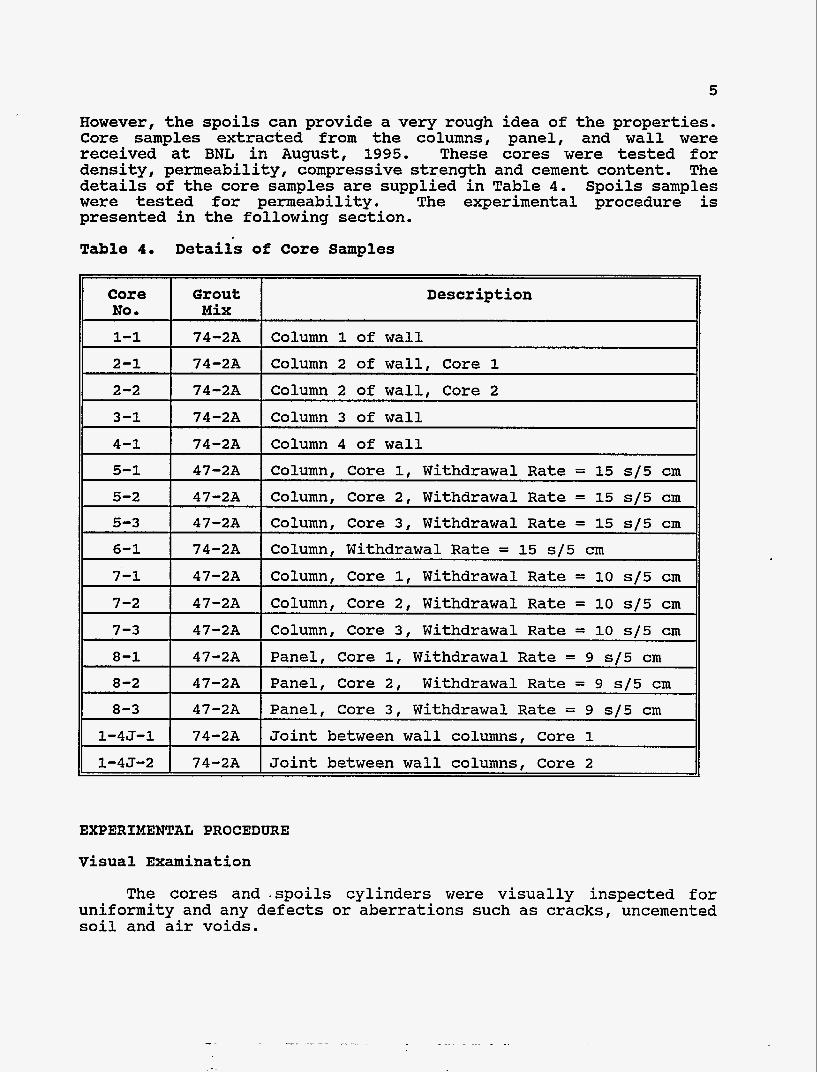
Core NO rn
However, the spoils can provide a very rough idea of the properties. Core samples extracted from the columns, panel, and wall were received at BNL in August, 1995. These cores were tested for density, permeability, compressive strength and cement content. The details of the core samples are supplied in Table 4. Spoils samples were tested for permeability. The experimental procedure is presented in the following section.
Table 4 . Detaiis of Core S a m p l e s
Grout Description Mix
1-1
2-1
2-2
3-1
74-2A Column 1 of wall
74-2A Column 2 of wall, Core 1
74-2A Column 2 of wall, Core 2
74-2A Column 3 of wall
4-1 I 74-2A I Column 4 of wall
6-1
7-1
7-2
7-3
I I ~~
~
74-2A Column, Withdrawal Rate = 15 s / 5 cm
47-2A Column, Core 1, Withdrawal Rate = 10 s / 5 cm
47-2A Column, Core 2, Withdrawal Rate = 10 s / 5 cm
47-2A Column, Core 3, Withdrawal Rate = 10 s / 5 cm
5-1 I 47-2A I Column, Core 1, Withdrawal Rate = 15 s / 5 cm I I
8-1
5-2 I 47-2A I Column, Core 2, Withdrawal Rate = 15 s / 5 cm I I
~~
47-2A Panel, Core 1, Withdrawal Rate = 9 s / 5 cm
5-3 I 47-2A I Column, Core 3, Withdrawal Rate = 15 s / 5 cm
8-2 I 47-2A I Panel, Core 2, Withdrawal Rate = 9 s / 5 cm I I
8-3 I 47-2A I Panel, Core 3 , Withdrawal Rate = 9 s / 5 cm
1-45-1 I 74-2A I Joint between wall columns, Core 1 I I
1-4J-2 I 74-2A I Joint between wall columns, Core 2
EXPERIMENTAL PROCEDURE
Visual Examination
The cores and .spoils cylinders were visually inspected for uniformity and any defects or aberrations such as cracks, uncemented soil and air voids.
6
Density
The density of .selected cores, was determined by measuring the The cores were tested in mass and volume after trimming the ends.
the Itas received" moisture condition.
Permeability (Hydraulic Conductivity)
The coefficient of permeability (hydraulic conductivity) was measured on the spoils samples and selected core samples. The rough ends of the samples were trimmed with a cut-off saw. The tested lengths of the samples varied depending on the original length of the core. The samples were saturated with de-aired tap water prior to testing. Measurements were conducted using a Tricon flexible wall triaxial cellpermeameter. The permeant was de-airedtap water. The applied pressure gradient was 207 kPa (30 psi) over the length of the specimen. The confining pressure applied to seal the latex membrane to the side surface of the grout specimen and to simulate an overburden pressure was 414 kPa (60 psi). The experimental set-up followed that given in ASTM D.5084-90. The same procedure and equipment was used in testing of laboratory prepared specimens.
=l
compressive Strength
-The compressive strength of selected cores was measured following ASTM C-39. Unfortunately, many of the cores were of insufficient length and the required aspect ratio of approximately 2 was fulfilled by only four cores. Thus, it was not possible to test the strength for each grouting condition and material used. The cores were tested in the dry, "as received1# condition so that the results would be representative of the in-situ strength.
Cement Content
The cement 'content of selected soil cement cores was measured following ASTM D 806-89. The procedure is based on determination of calcium oxide through precipitation of calcium oxalate. Samples of cement, slag and soil were also tested since these materials contribute to the calcium content of the soil cement. For grouts containing slag, the cementitious (cement + slag) content was determined. The calculation was based on the assumption that the cementitious content was comprised of 40% slag/60% cement ratio by weight. The results of the cement content analysis must not neglect the inherent variability in calcium content of the soil. Therefore, there is uncertainty in the cement content results due to the non- * uniformity of the soil.

7
RESULTS
Visual Appearance
The soil cement cores were relatively uniform in appearance and were hard and dense. The only exception to this was Core No. 1-4J-1 discussed below. The cores contained pockets of uncemented soil and air voids. The volumetric proportion of voids and clumps of soil was small. to 10 mm in diameter and were discontinuous. Occasionally, the clumps of soil were up to 20 mm diameter. No continuous strata of uncemented soil were observed. The individual pockets of soil probably resulted from localized incomplete mixing.
The clumps of uncemented soil and air voids were usually 5 '
The core samples were significantly more uniform and homogeneous than cores taken from previous permeation grouting field trials at the same site. The results of the tests on permeation grouted soil using microfine cement grouts were given in the FY '94 Annual Report. Penetration of the microfine cement grout was predictably limited to gravel layers and caused fracture of fine soil. Based on visual appearance, the jet grouted cores confirm that jet grouting is a much more reliable and uniform means of constructing subsurface barriers than permeation grouting forthe site conditions and for cementitious grouts. Permeation grouting is deemed totally unsuited to in-situ containment of the landfill under consideration.
The cores that were labelled as joints between columns did not show a distinct boundary between two halves. However, Core No. 1-4J- 1 did show a discontinuity in the form of a 10 mm thick section of uncemented soil extending 50 mm into the core. This may suggest a gap between columns. Due to the non-uniformity, this core could not be tested.
Hairline microcracks were observed on the surface of Cores 6-1 and 5-2. It was not clear whether the cracks were an artefact of coring or had developed in-situ. Coring is well known to disturb the integrity of cement-based materials. This is due to mechanical and heat effects. It is also possible that the cracks occurred due to excessive drying after removal from the columns or if the columns themselves were exposed to excessive drying conditions. The soil cements were designed for a subsurface environment, rather than above ground. Thus, ex-situ cracking is not a condemnation of the material.
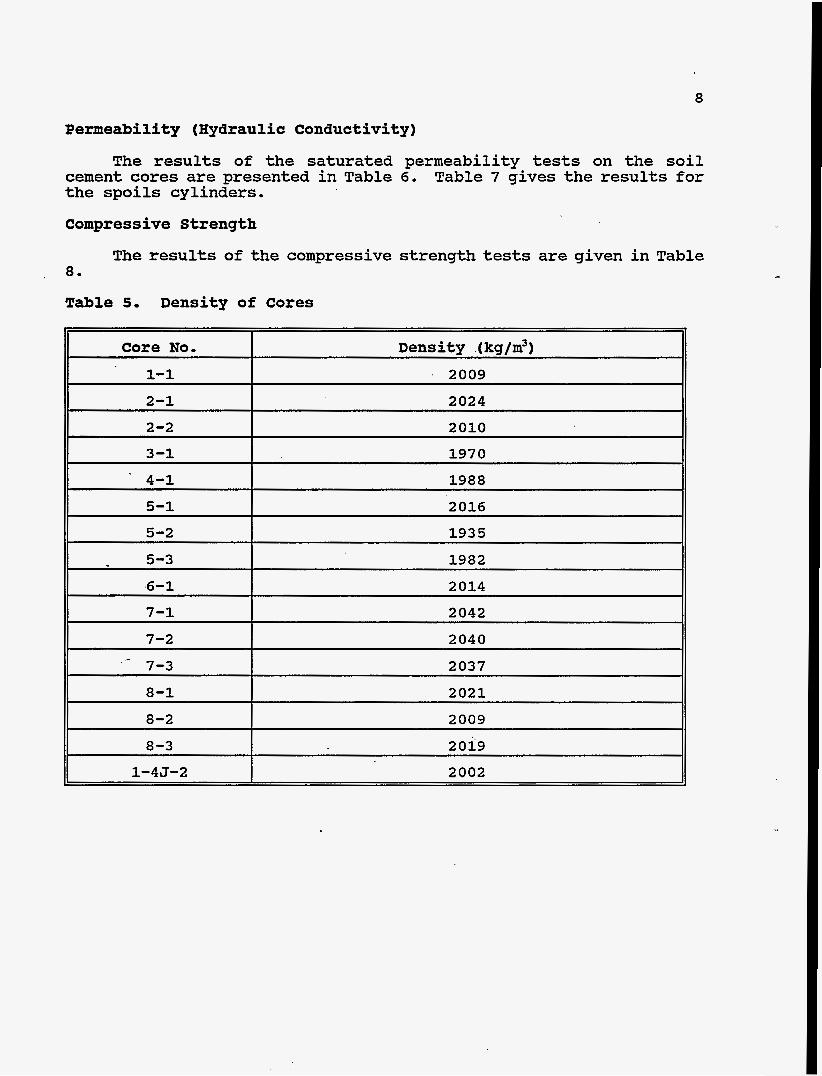
Density
The densities of the tested cores are given in Table 5. The average core density was 2006 kg/m3 and the standard deviation was 30 kg/m3.
8
1-1
2-1
2-2
3-1
. 4-1
5-1
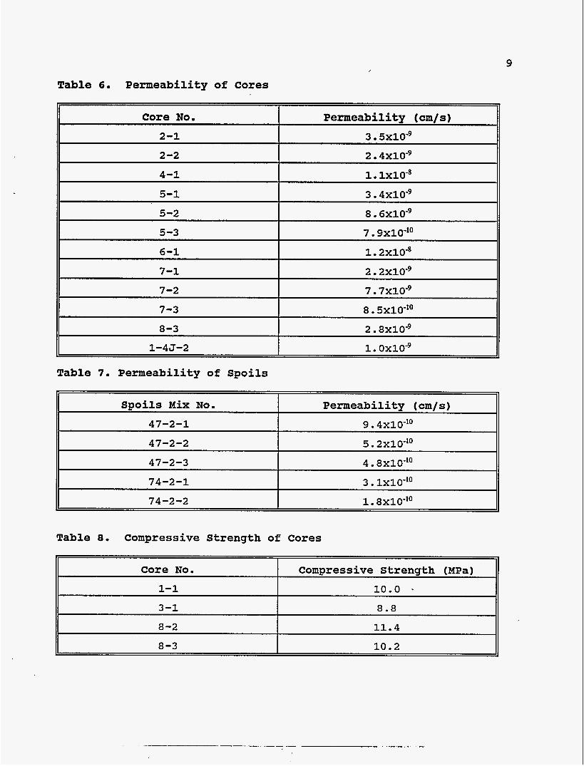
Permeability (Hydraulic Conductivity)
2009
2024
2010
1970
1988
2016
The results of the saturated permeability tests on the soil Table 7 gives the results for cement cores are presented in Table 6.
the spoils cylinders.
5-2
5-3
6-1
7-1
7-2
Compressive Strength
The results of the compressive strength tests are given in Table 8.
Table 5. Density of Cores
1935
1982
2014
2042
2040
Core No. I Density .(kg/m3)
- 7-3
8-1
2037
2021
8-3
1-45-2
2019
2002
9
Spoils Mix No.
47-2-1
47-2-2
47-2-3
74-2-1
74-2-2
Table 6. Permeability of Cores
Permeability (cm/s)
9.4xlO-'O
5. 2x1o-l0
4 . 8 ~ 1 0 - l ~
3 . lxlo-lo 1 . 8 ~ 1 0 - ' ~
Table 7. Permeability of Spoils
Core No.
1-1
Compressive Strength (MPa)
1 0 . 0 *
Table 8. Compressive Strength of Cores
8-3
I I
10.2
3-1 8 . 8 I
8-2 1 1 . 4

10
Core No. Cementitious Content (%I
2-1 18.5
5-1 17.2
6-1 16.0
7-3 23.8
8-1 26.4
Cementitious Content
Cementitious content ( ks/m3 1 374
347
322
484
533
Table 9 presents the results of the cementitious content The corresponding cementitious content analysis on the tested cores.
in kg/m3 estimated from density measurements is presented also.
Table 9. Cementitious Content of Cores
DISCUSSION
When analyzing and considering the implications of the results it is imperative to realize that the number of samples is statistically very small. For a more statistically valid representation many more samples would need to be recovered and tested. Funding levels did not permit this. Therefore, the results can only be used as an indication of the likely properties of the jet grouted columns and cannot be considered as statistically adequate. The effect of coring on the integrity of the samples also requires consideration. Thus, the disturbed samples do not necessarily represent the true in-situ properties and behaviour.
It is not possible to make a direct comparison between the laboratory and field placed samples. This is because the materials prepared in the laboratory had a known value of water/cementitious ratio (w/c). In contrast, the field placed soil cement had an unknown value of w/c due to the use of water as a drilling fluid and the subsequent soaking of the soil. This excess water elevated the final value of w/c for the soil cement. It is pointed out that the original test plan prepared by BNL in April 1994 stipulated that grout should be used as a drilling fluid in preference to water for this reason.
The w/c is the single most important factor controlling permeability, strength and durability of cementitious materials. The entire purpose of using superplasticized grouts was to reduce the value of w/c so that a superior material would be produced. However,
11
the effective dilution of the soil cement by an unknown amount negated the use of the superplasticized grout.. The detrimental effect of using water as a drilling fluid on the properties of soil cement has been reported previously (Adaska et al., 1992). Obviously, the use of water during drilling will decrease strength, increase permeability, and reduce durability. Any future work with superplasticized grouts must use grout as the lubricant otherwise the benefits and degree of control over final properties are lost.
The possibility of analyzing the cores for original water content was investigated. Together with the cementitious content, the original water content could be used to determine the water/cementitious material ratio of the placed material.
The procedure considered for determination of the original water content is given in British Standard 1881-Part 6. This standard is for testing of concrete and it is unknown if it has been applied to soil cement. The procedure involves determination of the water equivalent to the capillary porosity at the time of setting and the combined water still present in the form of hydrates. The method is not applicable to concrete with high coarse porosity (i. e. air voids) since this will bias the determined value of capillary porosity. Since the jet grouted cores did contain a certain degree of porosity due to air voids and pockets of uncemented soil, it was believed that this method would give dubious results. Therefore, the method was not used.
The would be values.
compressive strength of the soil cements was lower than expected if the w/c had been maintained at the designed However, the strength remained adequate for a subsurface
barrier. It was unfortunate that more cores could not be tested to obtain a better representation of the strengths for the different mixes.
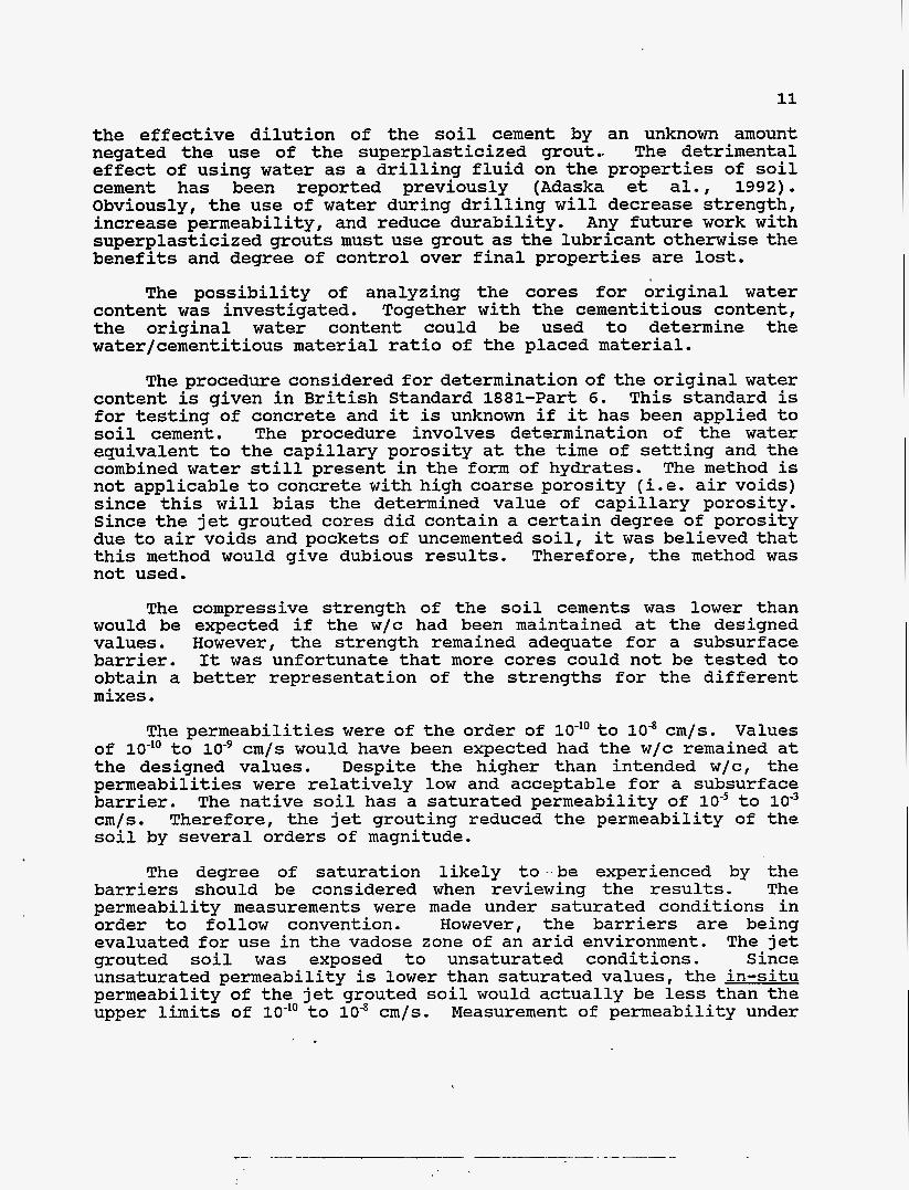
The permeabilities were of the order of lo-’’ to cm/s. Values of lo-’’ to lo-’ cm/s would have been expected had the w/c remained at the designed values. Despite the higher than intended w/c, the permeabilities were relatively low and acceptable for a subsurface barrier. The native soil has a saturated permeability of lo-’ to 10” cm/s. Therefore, the jet grouting reduced the permeability of the soil by several orders of magnitude.
The degree of saturation likely to be experienced by the barriers should be considered when reviewing the results. The permeability measurements were made under saturated conditions in order to follow convention. However, the barriers are being evaluated for use in the vadose zone of an arid environment. The jet grouted soil was exposed to unsaturated conditions. Since unsaturated permeability is lower than saturated values, the in-situ permeability of the jet grouted soil would actually be less than the upper limits of lo-*’ to cm/s. Measurement of permeability under
12
unsaturated conditions is less well defined but should be considered in future work.
An important finding is that the soil cement possessed low permeability despite the elevated w/c. This indicates the somewhat forgiving nature of the cementitious grout. The one sample of a joint (1-4J-2) had a relatively low permeability compared to the other values .
The permeability results indicate a relatively high degree of scatter. This is a reflection of the small number of samples tested, variability in the soil with depth, and the possible damage induced by coring. In addition, the inefficient grout mixing equipment used may have contributed to sample variability. A better approach would be to evaluate the hydraulic properties of the jet grouted columns in-situ. Such an approach could also be used to evaluate barrier continuity by testing across several interconnected columns. This would give a more representative measure of overall permeability rather than discrete core samples. Furthermore, results reported by Adaska et al. (1992) indicated that core samples had permeabilities 10 to 100 times greater than those measured from embedded piezometers or moulded fluid samples. Use of piezometers is recommended for future barrier testing.
Cores from permeation grouting trials using microfine cement grout had permeabilities ranging from to cm/s. The results were documented in the FY ‘94 Annual Report. Although the small number of samples tested makes statistically meaningful comparisons difficult, the indications are that the jet grouted cores have lower permeabilities.
The degree of variability and the small number of samples tested for each mix. make statistically valid comparisons between the different grouts dubious. It is not possible to determine the best mix based on the available results. Only a general statement that the magnitude of permeability showed a similar range for the different grouts can be made.
The permeabilities of the moulded spoils samples were lower and more consistent than for the core samples. The mix proportions of the spoils probably differed from the core samples. The lower permeabilities are partially due to the wet curing conditions which promoted cement hydration. The fact that the spoils had more consistent values of permeability than the cores is indicative of possible damage during coring.
The cementitious contents of the cores were much lower than specimens prepared in the laboratory with the same grouts. The results may have been influenced by the inherent variability in the calcium content in the soil. If it assumed that the results are a true representation then the low cementitious contents assist in

13
explanation of the higher permeabilities and lower strengths. The permeability results of the cores can be compared with laboratory prepared specimens with similar cementitious contents, keeping in mind that the w/c values may differ. Studies performed in FY '93 showed that the in-situ cured permeability of soil cements with cementitious contents of 3 9 1 and 315 kg/m3 .were 9 . 5 ~ 1 0 ' ~ and 2 . 2 ~ 1 0 ' ~ cm/s, respectively. The correspondingw/c values were 1.15 and1.38, respectively. These permeability values are of a similar magnitude to those measured on the majority of the cores.
Given the small size of the samples tested for cementitious content compared with the size of the columns and the variation in calcium content of the raw soil, it is not appropriate to make definitive conclusions on the correlation between withdrawal speed and cementitious content. However, it is noteworthy that the highest cementitious content was measured on the panel. The grout used in the panel had the highest cementitious content.
CONCLUSIONS
Jet grouting with superplasticized cementitious grouts was successful in producing columns and panels in-situ at the test site. Tests performed on core samples extracted from the jet grouted soil showed that saturated permeability ranged from lo-'' to cm/s and compressive strength ranged from 8.8 to 1 1 . 4 MPa. The permeability measured under saturated conditions represents the upper limit for barriers placed in the unsaturated vadose zone. Permeabilities were higher.than expected and this was attributed to the use of water has a drilling fluid prior to jet grouting and the resultant increase in the water/cementitious material ratio of the final product. Excursions in water/cementitious material ratio through pre-drilling with water negate the purpose of using superplasticizers. Cementitious content of the jet grouted soil was lower than expected and this, together with high water/cementitious material ratio, resulted in lower compressive strengths. However, both the strength an permeability values were acceptable for a subsurface barrier.
REFERENCES
Adaska, W.S., Bruin, W.T., and Day, S . R . , IIRemediation of Oil Refinery Sludge BasinI8, Cement Industry Solutions to Waste Management, Proceedings of First International Symposium, Calgary, 119-134, 1992 .
Allan, M.L. and Kukacka, L.E., In-Situ Containment and Stabilization of Buried Waste, FY '94 Annual Report, BNL 60977, 1994 .
Allan, M.L. and Kukacka, L.E., In-Situ Containment and Stabilization of Buried Waste, FY '93 Annual Report, BNL 49709, 1993.