Embed Size (px)
Citation preview

BASIC TURBO MODEL WITH UNSTRUCTURED MESH
© Fluent Inc., Mar-06 8-1
8. BASIC TURBO MODEL WITH UNSTRUCTURED MESH
This tutorial employs a simple turbine blade configuration to illustrate the basic turbo
modeling functionality available in GAMBIT. It illustrates the steps and procedures
required for importing data that describes the turbo blade, creating a geometric model that
describes the flow region surrounding the blade, meshing the model, and exporting the
mesh. The example presented here uses 3-D boundary layers to control the shape of the
mesh in the regions immediately adjacent to the blade and employs an unstructured hexa-
hedral mesh.
In this tutorial, you will learn how to:
• Import a turbo data file
• Create a turbo profile
• Modify a turbo profile to affect the shape of a turbo volume
• Create a turbo volume
• Define turbo zones
• Apply 3-D boundary layers to a turbo volume
• Mesh a turbo volume
• View a turbo volume mesh using both 3-D and 2-D perspectives
• Export a turbo volume mesh
8.1 Prerequisites
Prior to reading and performing the steps outlined in this tutorial, you should familiarize
yourself with the steps, principles, and procedures described in Tutorials 1, 2, 3, and 4.

Problem Description BASIC TURBO MODEL WITH UNSTRUCTURED MESH
8-2 © Fluent Inc., Mar-06
8.2 Problem Description
Figure 8-1 shows the turbomachinery configuration to be modeled and meshed in this
tutorial. The configuration consists of a turbine rotor on which are affixed 60 identical
blades, each of which is spaced equidistant from the others on the rotor hub. Each blade
includes a concave (pressure) side and a convex (suction) side, and the rotor rotates
counterclockwise about the x-axis, extracting work from the fluid (air) as it flows between
the blades (see Figure 8-2).
Figure 8-1: 60-blade turbine rotor

BASIC TURBO MODEL WITH UNSTRUCTURED MESH Problem Description
© Fluent Inc., Mar-06 8-3
Outlet flow
Inlet flow
Figure 8-2: Turbine rotor blade configurations
The overall goal of this tutorial is to create a geometric model of the flow region immedi-
ately surrounding one of the turbo blades and to mesh the model using an unstructured
hexahedral mesh.

Strategy BASIC TURBO MODEL WITH UNSTRUCTURED MESH
8-4 © Fluent Inc., Mar-06
8.3 Strategy
In general, the GAMBIT turbo modeling procedure includes seven basic steps:
1) Creating or importing edge data that describes the turbo profile
2) Creating the turbo profile
3) Creating the turbo volume
4) Assigning zone types to regions of the turbo volume
5) Decomposing the turbo volume
6) Meshing the turbo volume
7) Viewing the turbo volume
This tutorial illustrates six of the seven steps listed above. The tutorial excludes the turbo
decomposition step, because the turbo volume is to be meshed using unstructured hexahe-
dral mesh elements. Turbo volume decomposition is primarily used to facilitate the crea-
tion of structured meshes (see Tutorial 9 in this guide).
NOTE: In this tutorial, the turbo-volume viewing operation (Step 7, above) is illustrated
in conjunction with the mesh examination step (see “Step 11:Examine the Mesh,” below).
BASIC TURBO MODEL WITH UNSTRUCTURED MESH Procedure
© Fluent Inc., Mar-06 8-5
8.4 Procedure
1. Copy the file
path/Fluent.Inc/gambit2.x/help/tutfiles/turbo_basic.tur
(where 2.x is the GAMBIT version number) from the GAMBIT installation area in
the directory path to your working directory.
2. Start GAMBIT using the session identifier “Basic_Turbo”.
Step 1: Select a Solver
1. Choose the solver from the main menu bar:
Solver → FLUENT 5/6
The choice of solver affects the types of options available in the Specify Boundary
Types form (see “Step 12:Specify Zone Types,” below). For some systems,
FLUENT 5/6 is the default solver. The currently selected solver is shown at the top
of the GAMBIT GUI.

Procedure BASIC TURBO MODEL WITH UNSTRUCTURED MESH
8-6 © Fluent Inc., Mar-06
Step 2: Import a Turbo Data File
Turbo data files contain information that GAMBIT uses to define the turbo profile
(see “Step 3:Create the Turbo Profile,” below). Such information includes: point data
that describes the shapes of the profile edges, edge-continuity data, and specification
of the rotational axis for the turbo volume.
1. Select the Import Turbo File option from the main menu bar.
File → Import → Turbo...
This command sequence opens the Import Turbo File form.
2. Click the Browse... button.
This action opens the Select File form.

BASIC TURBO MODEL WITH UNSTRUCTURED MESH Procedure
© Fluent Inc., Mar-06 8-7
a) In the Files list, select turbo_basic.tur.
b) On the Select File form, click Accept.
3. On the Import Turbo File form, click Accept.
GAMBIT reads the information contained in the data file and constructs the set
of edges shown in Figure 8-3. The two straight edges shown in the figure describe
the hub and casing for the turbo volume. The two sets of curved edges constitute
cross sections of a single turbo blade.
Hub edge
Casing edge
Blade cross sections
Figure 8-3: Imported turbo geometry

Procedure BASIC TURBO MODEL WITH UNSTRUCTURED MESH
8-8 © Fluent Inc., Mar-06
Step 3: Create the Turbo Profile
The turbo profile defines the basic characteristics of the turbo volume, including the
shapes of the hub, casing, and periodic (side) surfaces. In GAMBIT, the edges that
describe the hub, casing, and blade cross sections are defined by means of their inlet
endpoint vertices.
1. Specify the hub, casing, and blade-cross-section edges of the turbo profile.
TOOLS → TURBO → CREATE PROFILE
This command sequence opens the Create Turbo Profile form.
In this step, you will specify vertices that define the hub, casing, and blade cross-
sections. In addition, you will specify the axis of revolution for the turbo configu-
ration. All instructions listed in this step refer to the vertex labels shown in Figure
8-4.

BASIC TURBO MODEL WITH UNSTRUCTURED MESH Procedure
© Fluent Inc., Mar-06 8-9
Hub Inlet
Casing Inlet
A
B
C
D
Blade Tips
Figure 8-4: Vertices used to specify the turbo profile
a) Activate the Hub Inlet list box on the Create Turbo Profile form.
To activate an input field, such as a list box, on any GAMBIT specification
form, left-click in the input box located adjacent to the field label—in this
case, “Hub Inlet”. (By default, GAMBIT activates the Hub Inlet field when you
open the Create Turbo Profile form.)
b) Select vertex A.
c) Activate the Casing Inlet list box.
d) Select vertex B.
e) Specify the x axis as the axis of revolution for the turbo configuration.
i. Click the Axis:Define pushbutton.
This action opens the Vector Definition form.

Procedure BASIC TURBO MODEL WITH UNSTRUCTURED MESH
8-10 © Fluent Inc., Mar-06
ii. Select the Direction:X-Positive option.
iii. On the Vector Definition form, click Apply.
f) Activate the Blade Tips list box.
g) Select vertex C.
h) Select vertex D.
! The order in which the Blade Tips vertices are selected is important to the
definition of a turbo profile. Specifically, the Blade Tips vertices must be
selected in order from the hub cross section to the casing cross section.
i) Click Apply to accept the vertex selections and create the turbo profile.
GAMBIT creates the turbo profile shown in Figure 8-5.

BASIC TURBO MODEL WITH UNSTRUCTURED MESH Procedure
© Fluent Inc., Mar-06 8-11
Rail edges
Rail edges
Medial edges
A
B
Figure 8-5: Turbo profile
The profile includes six new edges, four of which are real edges and two of which
are virtual edges. The four real edges are circular arc (“rail”) edges that are
formed by revolving the hub and casing endpoint vertices about the axis of revo-
lution for the profile. The two virtual edges are “medial” edges, the centermost
shapes of which represent the mean shapes of the blade cross sections. The end-
point vertices of the medial edges are hosted by the rail edges, and the medial
edges are defined such that they pass through the leading and trailing vertices of
the blade cross sections. The medial edges define the shapes of the periodic sur-
faces on the turbo volume (see “Step 5:Create the Turbo Volume,” below).

Procedure BASIC TURBO MODEL WITH UNSTRUCTURED MESH
8-12 © Fluent Inc., Mar-06
Step 4: Modify the Inlet and Outlet Vertex Locations
It is often useful to control the shape of the turbo volume such that its inlet and outlet
surfaces represent smooth flow transitions to and from the inlet and outlet ends,
respectively, of the turbo blade. In GAMBIT, you can control the shape of the turbo
volume by adjusting the positions of the medial-edge endpoint vertices prior to con-
structing the volume.
1. Open the Slide Virtual Vertex form.
TOOLS → TURBO → SLIDE VIRTUAL VERTEX
This command sequence opens the Slide Virtual Vertex form.
a) Select the inlet endpoint vertex of the medial edge for the casing blade cross
section (vertex A in Figure 8-5, above).
b) In the U Value field, enter the value 0.999.
As an alternative to entering a value in the U Value field, you can select the
vertex in the graphics window and drag it along its host rail edge until the U
Value field value is 0.999.
c) Retain the Move With Links (default) option.

BASIC TURBO MODEL WITH UNSTRUCTURED MESH Procedure
© Fluent Inc., Mar-06 8-13
The Move With Links option specifies that GAMBIT is to apply the current Slide
Virtual Vertex specifications to all medial-edge inlet endpoint vertices in addi-
tion to the selected vertex.
d) Click Apply to accept the new position of the medial-edge inlet endpoint vertices.
e) Select the outlet endpoint vertex of the medial edge for the casing blade cross
section (vertex B).
f) In the U Value field, enter the value 0.019.
g) Retain the Move With Links (default) option.
h) Click Apply to accept the new position of the medial-edge outlet endpoint vertices.
The modified turbo profile appears as shown in Figure 8-6.
Figure 8-6: Turbo profile with modified inlet and outlet vertex locations

Procedure BASIC TURBO MODEL WITH UNSTRUCTURED MESH
8-14 © Fluent Inc., Mar-06
Step 5: Create the Turbo Volume
A “turbo volume” is a 3-D region—which is defined by a set of one or more geomet-
ric volumes—that represents the flow environment surrounding the turbo blade. The
turbo volume characteristics are determined by the turbo profile and by specification
of the number of blades on the rotor (or angle between blades), the tip clearance, and
the number of spanwise sections. This example does not include a tip clearance but
does include spanwise sectioning.
1. Specify the pitch and number of spanwise sections for the turbo volume.
TOOLS → TURBO → CREATE TURBO VOLUME
This command sequence opens the Create Turbo Volume form.
a) In the Pitch text box, enter 60.
b) On the Pitch option button (located to the right of the Pitch text box), select the
Blade count option.
c) In the Spanwise Sections text box, enter 2.
d) Click Apply.
GAMBIT creates the turbo volume shown in Figure 8-7.

BASIC TURBO MODEL WITH UNSTRUCTURED MESH Procedure
© Fluent Inc., Mar-06 8-15
Casing face
Hub faceInlet
faces
Outlet
faces
Figure 8-7: Turbo volume—consisting of two geometric volumes

Procedure BASIC TURBO MODEL WITH UNSTRUCTURED MESH
8-16 © Fluent Inc., Mar-06
Step 6: Define the Turbo Zones
This step standard zone types to surfaces of the turbo volume. The zone-type specifi-
cations determine which faces are linked for meshing. In addition, GAMBIT auto-
matically associates turbo zone types to boundary zone definitions for some solvers.
1. Specify the faces that constitute the hub, casing, inlet, outlet of the turbo volume, as
well as the pressure and suction sides of the turbo blade.
TOOLS → TURBO → DEFINE TURBO ZONES
This command sequence opens the Define Turbo Zones form.
a) Activate the Hub list box.
b) Select the bottom (hub) face of the turbo volume (see Figure 8-7, above).
c) Activate the Casing list box.
d) Select the top (casing) face of the turbo volume.
e) Activate the Inlet list box.
f) Select the two inlet faces.
g) Activate the Outlet list box.
h) Select the two outlet faces.

BASIC TURBO MODEL WITH UNSTRUCTURED MESH Procedure
© Fluent Inc., Mar-06 8-17
i) Activate the Pressure list box.
j) Select the six faces on the inner-curve (pressure side) of the turbo blade.
k) Activate the Suction list box.
l) Select the six faces on the outer-curve (suction side) of the turbo blade.
m) Click Apply to assign the turbo zone types.

Procedure BASIC TURBO MODEL WITH UNSTRUCTURED MESH
8-18 © Fluent Inc., Mar-06
Step 7: Apply 3-D Boundary Layers
For turbo models, 3-D boundary layers allow you to ensure the creation of high-
quality mesh elements in regions adjacent to the turbo blade surfaces. Such boundary
layers are particularly useful when the turbo volume is to be meshed using an
unstructured meshing scheme.
1. Specify the hub, casing, and blade-cross-section edges of the turbo profile.
TOOLS → TURBO → CREATE/MODIFY BOUNDARY LAYERS
This command sequence opens the Create Boundary Layer form.

BASIC TURBO MODEL WITH UNSTRUCTURED MESH Procedure
© Fluent Inc., Mar-06 8-19
a) In the First row text box, enter a value of 1.
b) In the Growth factor text box, enter a value of 1.2.
c) In the Rows text box, specify a value of 5, either by direct input of the value or by
sliding the Rows slider bar.
GAMBIT automatically calculates a Depth value of 7.4416, based on the First
row, Growth factor, and Rows specifications.
d) Select the Internal continuity option.
e) In the Attachment input field, select the Faces option.
f) Activate the Faces list box, and select the 12 faces that comprise the pressure and
suction sides of the turbo blade.
g) Click Apply.
Figure 8-8 shows the 3-D boundary layers projected onto the three spanwise
surfaces of the turbo volume.
Figure 8-8: Turbo volume with 3-D boundary layers

Procedure BASIC TURBO MODEL WITH UNSTRUCTURED MESH
8-20 © Fluent Inc., Mar-06
By default, GAMBIT displays the boundary layers in the graphics window
unless they are made invisible by direct user action. The boundary layer dis-
play can make it difficult to view the model during subsequent steps in the
modeling process; therefore, it is advisable to render the boundary layers
invisible before continuing the tutorial.
2. Select the SPECIFY DISPLAY ATTRIBUTES command button on the Global
Control toolpad.
This action opens the Specify Display Attributes form.
a) Select the B. Layers check box.
b) Select the Visible:Off option.
c) Click Apply.

BASIC TURBO MODEL WITH UNSTRUCTURED MESH Procedure
© Fluent Inc., Mar-06 8-21
GAMBIT turns off the display of the boundary layers.
d) Close the Specify Display Attributes form.

Procedure BASIC TURBO MODEL WITH UNSTRUCTURED MESH
8-22 © Fluent Inc., Mar-06
Step 8: Mesh the Blade Cross-Section Edges
In this step, you will pre-mesh the edges that represent the blade cross sections,
thereby ensuring a finer mesh in proximity to the turbo blade surfaces than is created
in the bulk of the turbo volume.
1. Mesh the centermost pressure-side edges of the turbo blade.
TOOLS → TURBO → MESH EDGES/FACES/VOLUMES
This command sequence opens the Mesh Edges form.
a) Activate the Edges list box, and select the three centermost edges on the pressure
side of the blade cross sections.
b) On the Grading:Type option button, retain Successive Ratio.

BASIC TURBO MODEL WITH UNSTRUCTURED MESH Procedure
© Fluent Inc., Mar-06 8-23
c) In the Ratio input field, enter a value of 1.02.
d) Select the Double sided option.
When you select the Double sided option, GAMBIT changes the Ratio input
field to Ratio 1 and displays a field named Ratio 2 that contains a ratio specifi-
cation identical to that of Ratio 1 (that is, 1.02).
e) On the Spacing option button, select Interval count.
f) In the Spacing text box, enter a value of 100.
g) Click Apply.
GAMBIT meshes the selected edges as shown in Figure 8-9. The Double sided
option with a ratio of 1.02 grades the edges such that mesh nodes are bunched
near the endpoint vertices of the edges.
Figure 8-9: Meshed centermost pressure-side edges of the turbo blade
2. Mesh the suction-side edges of the turbo blade.
a) Activate the Edges list box, and select the three centermost edges on the suction
side of the blade cross sections.
b) On the Grading:Type option button, retain Successive Ratio.

Procedure BASIC TURBO MODEL WITH UNSTRUCTURED MESH
8-24 © Fluent Inc., Mar-06
c) In the Ratio input field, enter a value of 1.02.
d) Select the Double sided option.
e) On the Spacing option button, retain Interval count.
f) In the Spacing text box, enter a value of 110.
g) Click Apply.
3. Mesh the leading edges of the turbo blade.
a) Activate the Edges list box.
b) Select the six edges (two edges on each cross section) on either side of the leading
vertices for the top, middle, and bottom blade cross sections.
! When selecting the edges, modify the edge senses, as necessary, such that
they point away from the leading vertices of the cross sections. When you
select an edge in the graphics window, GAMBIT automatically displays an
arrowhead in the middle of the edge to indicate the sense of the edge. To
change the sense of any selected edge, Shift-middle-click the edge. (NOTE: If
the sense-direction arrowhead is obscured by mesh nodes displayed on the
edge, set the Interval count to 1 while selecting edges for meshing.)
c) On the Grading:Type option button, retain Successive Ratio.
d) In the Ratio input field, enter a value of 1.05.
The single-sided meshing option with a ratio of 1.05 grades the edges such
that mesh nodes are bunched near the leading vertices of the edges—that is, in
the regions of highest curvature for the edges.
e) On the Spacing option button, retain Interval count.
f) In the Spacing text box, enter a value of 15.
g) Click Apply.
4. Mesh the trailing edges of the turbo blade.
a) Activate the Edges list box.
b) Select the six edges (two edges on each cross section) on either side of the trailing
vertices for the three blade cross sections.

BASIC TURBO MODEL WITH UNSTRUCTURED MESH Procedure
© Fluent Inc., Mar-06 8-25
c) On the Grading:Type option button, retain Successive Ratio.
d) In the Ratio input field, enter a value of 1.
e) On the Spacing option button, retain Interval count.
f) In the Spacing text box, enter a value of 3.
g) Click Apply.
Figure 8-10 shows the final edge-mesh configuration for the turbo blade cross
sections.
Figure 8-10: Meshed edges of turbo blade cross sections

Procedure BASIC TURBO MODEL WITH UNSTRUCTURED MESH
8-26 © Fluent Inc., Mar-06
Step 9: Mesh the Center Spanwise Face
To create an unstructured mesh for this example, it is best to pre-mesh the middle
spanwise face and to employ the middle face as a source face for a Cooper meshing
scheme applied to the two geometric volumes. The use of the middle face as a source
face ensures that the Cooper scheme produces a mesh with minimal distortion
throughout the turbo volume.
1. Mesh the center spanwise face of the turbo volume.
TOOLS → TURBO → MESH EDGES/FACES/VOLUMES
R
This command sequence opens the Mesh Faces form.
a) Activate the Faces list box, and select the middle spanwise face.
GAMBIT automatically selects the Quad and Pave Scheme options based on
the face characteristics.

BASIC TURBO MODEL WITH UNSTRUCTURED MESH Procedure
© Fluent Inc., Mar-06 8-27
b) On the Scheme:Elements option button, retain the Quad option.
c) On the Scheme:Type option button, retain the Pave option.
d) On the Spacing option button, select the Interval size option.
e) In the Spacing text box, enter a value of 5.
f) Click Apply.
GAMBIT meshes the middle spanwise face as shown in Figure 8-11.
Figure 8-11: Meshed center spanwise face

Procedure BASIC TURBO MODEL WITH UNSTRUCTURED MESH
8-28 © Fluent Inc., Mar-06
Step 10: Mesh the Volumes
In this step, you will apply a Cooper meshing scheme to the two geometric volumes
that comprise the turbo volume.
1. Mesh the turbo volume.
TOOLS → TURBO → MESH EDGES/FACES/VOLUMES
R
This command sequence opens the Mesh Volumes form.
a) Activate the Volumes list box, and select the both of the geometric volumes that
comprise the turbo volume.
GAMBIT automatically selects the Scheme:Elements:Hex/Wedge and Scheme:
Type:Cooper options for the selected volumes.
b) Retain the automatically selected Scheme options.
c) On the Spacing option button, select Interval size.
BASIC TURBO MODEL WITH UNSTRUCTURED MESH Procedure
© Fluent Inc., Mar-06 8-29
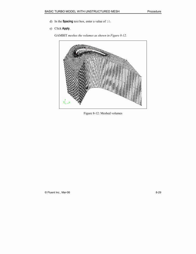
d) In the Spacing text box, enter a value of 10.
e) Click Apply.
GAMBIT meshes the volumes as shown in Figure 8-12.
Figure 8-12: Meshed volumes

Procedure BASIC TURBO MODEL WITH UNSTRUCTURED MESH
8-30 © Fluent Inc., Mar-06
Step 11: Examine the Mesh
1. Select the EXAMINE MESH command button at the bottom right of the Global
Control toolpad.
This action opens the Examine Mesh form.
The Examine Mesh form allows you to view various mesh characteristics for the
3-D mesh. For example, Figure 8-13 displays volume mesh elements for which the
EquiSize Skew parameter is between 0.4 and 0.5 for this example.
a) Click Update at the bottom of the Examine Mesh form.

BASIC TURBO MODEL WITH UNSTRUCTURED MESH Procedure
© Fluent Inc., Mar-06 8-31
GAMBIT does not automatically update the graphics display when you open
the Examine Mesh form or modify its specifications, such as Display Type or
Quality Type. To update the graphics display, you must click the Update push-
button located at the bottom of the form. GAMBIT displays the Update
pushbutton label in red lettering whenever the display needs to be updated to
reflect the current Examine Mesh specifications.
Some Examine Mesh operations automatically update the graphics display.
For example, if you select the Display Type:Range option and click one of the
histogram bars, GAMBIT automatically updates the display.
Figure 8-13: Hexahedral mesh elements—EquiSize Skew = 0.4–0.5
The Examine Mesh command and options can be used in conjunction with the View
Turbo Volume command to view 2-D characteristics of the mesh on the hub,
casing, and spanwise surfaces. Such views are particularly useful when examining
the mesh on highly twisted blades.
2. Display the middle spanwise surface in a cascade turbo view.
TOOLS → TURBO → VIEW TURBO VOLUME
This command sequence opens the View Turbo Volume form.

Procedure BASIC TURBO MODEL WITH UNSTRUCTURED MESH
8-32 © Fluent Inc., Mar-06
a) Select the Cascade surface:Spanwise option.
b) In the Spanwise text box, enter a value of 1.
The Cascade surface specifications described above specify a flattened, 2-D
display of the middle spanwise surface of the turbo volume.
c) Click Apply.
Figure 8-14 displays face mesh elements for which the EquiSize Skew parameter is
between 0.1 and 0.3 for this example. (NOTE: To view the 2-D face elements
shown in Figure 8-14, select the Display Type: 2D Element option on the Examine
Mesh form, and specify the display of quadrilateral ( ) elements.)

BASIC TURBO MODEL WITH UNSTRUCTURED MESH Procedure
© Fluent Inc., Mar-06 8-33
Figure 8-14: Quadrilateral mesh elements—EquiSize Skew = 0.1–0.3
Figure 8-15 displays a zoomed view of the mesh in the region surrounding the
blade tip.
Figure 8-15: Quadrilateral mesh elements—zoomed view near blade tip

Procedure BASIC TURBO MODEL WITH UNSTRUCTURED MESH
8-34 © Fluent Inc., Mar-06
d) Select the Off option and click Apply to turn off the cascade turbo view before
specifying zone types.

BASIC TURBO MODEL WITH UNSTRUCTURED MESH Procedure
© Fluent Inc., Mar-06 8-35
Step 12: Specify Zone Types
You can use the Specify Boundary Types command to apply solver-specific boundary
zone specifications to surfaces of the turbo volume. For some solver options, includ-
ing Fluent 5/6, GAMBIT automatically assigns such boundary zone specifications.
1. Check the automatically applied boundary zone types.
ZONES → SPECIFY BOUNDARY TYPES
This command sequence opens the Specify Boundary Types form.
Procedure BASIC TURBO MODEL WITH UNSTRUCTURED MESH
8-36 © Fluent Inc., Mar-06
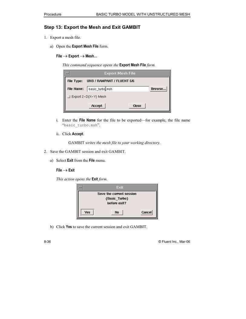
Step 13: Export the Mesh and Exit GAMBIT
1. Export a mesh file.
a) Open the Export Mesh File form.
File → Export → Mesh…
This command sequence opens the Export Mesh File form.
i. Enter the File Name for the file to be exported—for example, the file name
“basic_turbo.msh”.
ii. Click Accept.
GAMBIT writes the mesh file to your working directory.
2. Save the GAMBIT session and exit GAMBIT.
a) Select Exit from the File menu.
File → Exit
This action opens the Exit form.
b) Click Yes to save the current session and exit GAMBIT.

BASIC TURBO MODEL WITH UNSTRUCTURED MESH Summary
© Fluent Inc., Mar-06 8-37
8.5 Summary
This tutorial demonstrates the use of the basic turbo modeling operations available in
GAMBIT. The edge data that describes the geometry of the turbo profile was imported
from a turbo data file, and the completed turbo profile was adjusted to affect the shape of
the turbo volume. The turbo volume was divided into two spanwise sections, each of
which was meshed by means of a Cooper scheme that employed the common face between
them as a source face. Three-dimensional boundary layers were applied to the surfaces of
the turbo blade to ensure a high-quality mesh in proximity to the turbo blade. Finally, the
mesh examining capabilities in GAMBIT were used in conjunction with the turbo
viewing capability to examine the 2-D mesh on the middle spanwise face.