Embed Size (px)
Citation preview

7SA511 V2.2
Numerical Line Protection RelayOperator Manual
Power
Blocked
1
2
3
4
5
6
7
8
9
0
1
2
3
4
1
1
1
1
1
Manual No. SG-8108-01


7SA511 Line Protection Relay Table of Contents
July 27, 1995 i
Table of Contents
User Guide
Chapter 1 Introduction .......................................................................................... 1-1
Chapter 2 Product Description .............................................................................. 2-1
Chapter 3 Acceptance Tests.................................................................................. 3-1
Chapter 4 Installation............................................................................................ 4-1
Chapter 5 Programming the Relay......................................................................... 5-1
Chapter 6 Displaying System and Relay Information.............................................. 6-1
Chapter 7 Commissioning the Relay...................................................................... 7-1
Chapter 8 Maintenance.......................................................................................... 8-1
Reference Guide
Reference A. Method of Operation............................................................................ A-1
Reference B. Hardware and Software........................................................................ B-1
Reference C. Communications................................................................................... C-1
Reference D. Specifications....................................................................................... D-1
Reference E. Settings Calculations.............................................................................E-1
Reference F. Setting Worksheets...............................................................................F-1
Reference G. Input/Output Functions........................................................................ G-1

7SA511 Line Protection Relay Table of Contents
ii July 27, 1995
The information contained herein is general in nature and not intended for specific application purposes. It does not relieve the user of
responsibility to use sound practices in application, installation, operation, and maintenance of the equipment purchased. Siemens reserves
the right to make changes in the specifications shown herein or to make improvements at any time without notice or obligation. Should a
conflict arise between the general information contained in this publication and the contents of drawings or supplementary material or both,
the latter shall take precedence.
Should further information be desired or should particular problems arise which are not covered sufficiently for the purchaser’s purposes,
the matter should be referred to your local sales office.
The contents of this manual should not become part of or modify any prior or existing agreement, commitment or relationship. The sales
contract contains the entire obligation of Siemens Energy & Automation, Inc. Any statements contained herein do not create new
warranties or modify an existing warranty.

7SA511 Line Protection Relay Chapter 1
July 27, 1995 1-1
Introduction
Table of Contents
1. Introduction ........................................................................................................................ 1-31.1 Using This Manual................................................................................................. 1-31.2 Glossary of Terms and Abbreviations..................................................................... 1-41.3 Relay Model Number............................................................................................. 1-6
List of Figures
Figure 1-1. Reading the 7SA511 Relay Model Number...........................................................1-7

7SA511 Line Protection Relay Introduction
July 27, 19951-2
This page intentionally blank

7SA511 Line Protection Relay Chapter 1
ll andeatures
1.3,
youon
ting
1. Introduction
1.1 Using This Manual
This operator’s manual is intended to provide you with all the information you need to instaoperate the Siemens 7SA511 Numerical Line Protection Relay. In addition to describing thvarious tasks of operation, the manual offers general information about the functions and feof the relay.
Several of the relay’s functions and features are optional, depending on the model orderingnumber. This manual identifies all of the relay’s options and frequently refers you to section“Relay Model Number,” so you can determine which options your relay has.
This manual is divided into two parts:
• The User Guide describes how to install, program, operate and maintain the relay, sowill need to read this part if you are to perform any of these tasks. General informatiabout the relay’s features and functions is also in this part of the manual.
• The Reference Guide includes the relay specifications, method of operation, relay setcalculations and worksheets, and information on the relay’s hardware, software, andcommunications capabilities. If you are responsible for the application and settingcalculation of the relay, you will need to read this part of the manual.
Refer to Table 1-1 for help in finding the information you need in this manual.
Table 1-1. Using This Manual.If you want to . . . Then read . . .learn more about the relay · Chapter 2, Product Description
· Reference A, Method of Operation· Reference B, Hardware & Software· Reference C, Communications
determine the optional function(s)available in your relay
· Section 1.3, Relay Model Number
install the relay · Chapter 4, Installationperform acceptance tests · Chapter 3, Acceptance Testsprogram the relay · Chapter 5, Programming the Relay
· Reference E, Setting Calculations· Reference F, Setting Worksheets· Reference G, Input/Output Functions
check relay status, target historylogs, and the event log
· Chapter 6, Displaying System and Relay Information
place the relay in service orperform maintenance
· Chapter 7, Commissioning the Relay· Chapter 8, Maintenance
review relay specifications · Reference D, Specifications
July 27, 1995 1-3

7SA511 Line Protection Relay Introduction
rate
t are
This manual assumes you are using the relay’s operator panel to program, maintain, and opethe relay. If you are using DIGSI® software or some other application to control the relay, referto the appropriate user guide when instructions in this manual are insufficient.
1.2 Glossary of Terms and Abbreviations
Following are definitions and descriptions of terms and abbreviations used in this manual thaunique to power systems and to Siemens relay technology in particular.
Abbreviations and AcronymsA/D analog-to-digitalAR automatic recloseCB circuit breakerC/O changeoverCT current transformerCW codewordDAR delayed automatic recloseE earth or groundEEPROM electrically erasable, programmable read only memoryE/F earth (ground) faultEPROM erasable, programmable read only memoryFD fault detection; fault detectorFNo function numberI.T. inverse timeLCD liquid crystal display (on the relay operator panel)LED light emitting diode (on the relay operator panel)LSA a substation (Siemens’ Localized Substation Automation system)m memorizedM/C manual closemcb or m.c.b. miniature circuit breakerNC normally closednm not memorizedNO normally openO/C overcurrentPC personal computerpcb printed circuit boardPCO parameter changeoverPLC power line carrierPOTT permissive overreach transfer trip (pilot protection scheme)PUTT permissive underreach transfer trip (pilot protection scheme)RAM random access memoryRAR rapid automatic recloseROM read only memoryTT transmit timeVT voltage transformer
July 27, 19951-4

7SA511 Line Protection Relay Chapter 1
or
ltage
e
renthort
the
alue
Termsannunciation 1. Activating the various relay outputs (LCD, LEDs, output relays)
when events occurs.2. Messages that appear on the operator panel LCD in the event log
target logs are also called annunciations.
binary input A relay input terminal that responds to the presence or absence of voon the terminal in a digital (on/off) manner.
block 1. Prevent normal operation or function.2. Group of memory addresses.
compensated(system)
The neutral system point is inductively grounded to compensate for thdistributed phase-to-ground system capacitance.
dead time Time allowed following fault clearance before attempting an automaticreclose.
drop-off Drop-out (used in the LCD text).
drop-out Return to a normal or no-fault state.
earth Electrical ground.
fault loop In phase-selective fault detection systems, this term describes the curpath for phase-to-phase or phase-to-ground faults. For example, if a scircuit occurs between phase 1 (L1) and phase 2 (L2), the fault loop isL1-L2. The currents and voltages of the fault loop are decisive whencalculating the distance to fault.
forward Direction—normally downstream towards the line or load (i.e., towardprotected component).
high-set An overcurrent protection element that operates independently of thedefinite time or inverse time elements and typically has a high pickup vand a small or zero (instantaneous) time delay.
isolated (system) The neutral system point is purposely not connected to ground(ungrounded).
marshalling Configuring the I/O units (LEDs, trip relays, etc.)
July 27, 1995 1-5

7SA511 Line Protection Relay Introduction
as
m
ed onureoltage,re
or noter is
*-ections
Termspickup Activation of a protection function either through detection of a fault or
a result of a binary input. The current and voltage levels or ratios thatcause a protection element to pick up are called pickup values.
reclaim time The no-fault time period following automatic reclose that defines asuccessful reclose
reverse Direction—normally upstream towards the bus or source (i.e. away frothe protected object).
stage A protection element; a group of protection parameters that, at aminimum, include pickup and time delay values.
starpoint Common connection point in wye-connected electrical equipment; theneutral connection.
target System device to which a command or signal is directed.
trip Activate a trip relay or open a circuit breaker.
1.3 Relay Model Number
The model number for your 7SA511 relay is printed on the relay’s nameplate, which is locatthe operator panel (see Figure 2-1 in Chapter 2, “Product Description”). As illustrated in Fig1-1, you can read your relay’s model number and determine the rated current, DC supply vtype of mounting (flush or surface), type of fault detection, and which optional functions yourelay has. Using the model number allows you to verify that you have the correct relay for thapplication.
This manual frequently refers you to the relay model number so you can determine whethera particular section is applicable to your relay and protected system. When the model numbused, the character(s) significant to the discussion is bold, and asterisks (*) are used to indicatethat the character is irrelevant to the discussion. For example, model number 7SA511*-**A5** A/E* means the relay does not have the automatic reclose feature, so you can skip the son automatic reclose.
July 27, 19951-6

7SA511 Line Protection Relay Chapter 1
J
F
Mounting construction
Fault detection options
Ground fault detection input
For grounded systems, ground current input for protected line onlyFor ungrounded systems, without parallel line compensationFor grounded systems, ground current input for parallel line compensation
Overcurrent fault detectionOvercurrent, Voltage-controlled Overcurrent, and Polygonal Impedance
fault detectionOvercurrent and Voltage-controlled Overcurrent fault detection
7SA511 A5Line Protection RelayRated current at 60/50 Hz AC
1 A5 ARated power supply voltage VDC
24, 48 VDC60, 110, 125 VDC220, 250 VDC
1
2
5
54
Surface mountingFlush mounting
Communications interface (rear port)
Automatic reclose (AR)/Parameter changeover (PCO)
NoneIsolated, hard-wiredIntegrated fiber optic
without ARwith AR 3-polewith AR 1/3-polewithout ARwith AR 3-polewith AR 1/3-pole
without PCOwithout PCOwithout PCOwith PCOwith PCOwith PCO
without PSwith PSwithout PSwith PS
without GFwithout GFwith GFwith GF
Power swing (PS)/High-resistance ground fault protection (GF) *
1
23
012
ABC
A
C
F
B
E
G
0
21
3
BC
* The Power swing (PS) option is only applicable when the fault detection system selected is the polygonal impedance detector (code = 2).The High-resistance ground fault (GF) protection is only applicable for grounded systems, i.e., the ground fault detection Input code must be0 or 2.
uly 27, 1995 1-7
igure 1-1. Reading the 7SA511 Relay Model Number.

7SA511 Line Protection Relay Introduction
July 27, 19951-8
This page intentionally blank

7SA511 Line Protection Relay Chapter 2
July 27, 1995 2-1
Product Description
Table of Contents
2. Product Description ............................................................................................................ 2-32.1 About the Relay..................................................................................................... 2-32.2 Relay Features....................................................................................................... 2-32.3 Relay Setting Types............................................................................................... 2-4
2.3.1 Relay Setting Descriptions (by Address Block)........................................ 2-52.4 Overview of Protection Functions.......................................................................... 2-8
2.4.1 Distance Protection ................................................................................. 2-82.4.2 Emergency Overcurrent Protection.......................................................... 2-102.4.3 Power Swing Protection (optional).......................................................... 2-102.4.4 Pilot Protection ....................................................................................... 2-102.4.5 High-Sensitivity Ground Fault Protection for Ungrounded Systems(optional)......................................................................................................... 2-102.4.6 High-Resistance Ground Fault Protection (optional)................................ 2-112.4.7 Automatic Reclose (optional).................................................................. 2-122.4.8 Distance-to-Fault Location...................................................................... 2-12
2.5 Additional Functions and Features of the Relay...................................................... 2-132.5.1 Secured Data Storage.............................................................................. 2-132.5.2 Serial Data Ports ..................................................................................... 2-132.5.3 Multiple Parameter Sets (optional).......................................................... 2-14

7SA511 Line Protection Relay Product Description
July 27, 19952-2
This page intentionally blank

7SA511 Line Protection Relay Chapter 2
,nd
edded), or6 LED
hedisplay
ions,
analyze
2. Product Description
2.1 About the Relay
The 7SA511 line protection relay is a microprocessor-based relay designed to provide fastreliable, and selective clearance of all kinds of ground and phase faults on overhead lines acables being fed from one point or multiple points. The system can be radial, ring, or meshtopography. The system starpoint can be solidly grounded, compensated (resonant grounisolated (ungrounded). This relay has 10 binary inputs, 5 trip relays, 11 signal relays, and 1indicators.
The relay can be flush or surface mounted and is easily programmed and operated using tcontrols and keypad on the operator panel. The LEDs on the operator panel continuously relay status and target indication. When prompted, the LCD shows the system settings,configuration settings, protection settings, measured values, calculated values, setting optevent messages, and other operational information.
The relay can be connected to a PC or to a substation control system, enabling the user todata stored in the relay’s memory and to monitor the relay’s alarms and status signals.
July 27, 1995 2-3

7SA511 Line Protection Relay Product Description
relaynt.
of the
and
2.2 Relay Features
· Microprocessor-Based Technology· Fully Numerical Design· Five Distance Zones, Phase and Ground· Polygonal Impedance Characteristic· Selectable Forward, Reverse or
Nondirectional· Separate R-Setting for Phase and
Ground· Seven Independent Time Delays· Fault Detector Options- Overcurrent- Voltage-Controlled Overcurrent- Impedance· Pilot Logic Schemes
- Permissive Overreach Transfer Trip(POTT)
- Permissive Underreach Transfer Trip(PUTT)
- Blocking- Unblocking- Directional Comparison- Directional Pilot Wire (requires
7PA5210)· Weak Feed Echo Keying Logic· Transient Blocking· Zone Extension Scheme· Reverse Interlock Bus Protection· Single/Three-Pole Trip· Single/Three-Pole Multi-Shot Reclosing· Loss of Potential Block· Overcurrent Protection as Backup for
Distance Protection· Power Swing Block/Trip
· Close-Onto-Fault Protection· Isolated Ground Fault Detection· Directional High Resistance Ground
Fault Protection· Nonvolatile Memory for Settings and
Targets· Programmable Binary Inputs, LEDs,
Signal and Trip Relays· Four Independent Setting Groups· Fault Locating· Parallel Line Compensation Option· Fault Target Data· Fault Waveform Capture (0.83 ms
resolution for 60 Hz frequency)· Operations Event Log· Circuit Breaker Operations Counter· Accumulated Circuit Breaker
Interrupted Current (per pole)· Real-Time Clock· Circuit Breaker Trip Test Function· Circuit Breaker Reclose Test· Metering Functions (On-line)
- Voltage- Current- Real Power (Watts)- Reactive Power (Vars)- Frequency- Impedances
· Two Serial Ports (one standard, oneoptional)
· IEC 870-5 Communication Standard· Self-Monitoring· Draw Out Construction
2.3 Relay Setting Types
The relay requires four types of settings. The settings, described below, determine how therecognizes and responds to operating conditions to protect your power apparatus equipmeEach relay is delivered with a set of parameters that are preprogrammed at the factory. Allpresettings are identified in Chapter 5, “Programming the Relay.”
· Operating settings define the conditions under which the relay will function. Theseinclude the setting of the real-time clock (time and date), choice of display language,
July 27, 19952-4

7SA511 Line Protection Relay Chapter 2
ntifyl
ted
asntltents.
ings
jority.3.3),
ble
puts,
t
e
choice of the data transmission rate for the front port. The operating settings also idewhat information is to be displayed in each of the two lines of the LCD for operationamessages and for fault messages.
The relay’s “Scope of Functions” settings are also considered part of the operatingsettings. These settings indicate which functions are activated (EXIST) and deactiva(NON-EXIST). Operating settings also indicate how the optional functions automaticreclose and parameter changeover will operate.
· System settings identify the protected power system and switchgear. Information suchthe system starpoint direction and condition, voltage transformer voltages, and curretransformer rated current is required. The relay’s distance protection and ground fauprotection functions use this information to compute the system’s protection requiremWhen the parameter changeover feature is available (see section 2.5.3), system settcan vary between the parameter sets.
· Protection settings such as for distance protection, pilot protection, and overcurrentprotection, specify the values that are used to identify fault conditions and are the maof settings the 7SA511 relay requires. Depending on your relay model (see section 1you may also need to indicate settings for power swing blocking protection or high-resistance ground fault protection. When the parameter changeover feature is availa(see section 2.5.3), protection settings can vary between the parameter sets.
· Relay configuration settings tell the relay how to process the input information andlogically associate it with the output devices. If desired, you can reassign the binary inannunciations, and the function of the relay’s output signals, trip relays, and LEDs.Configuration is also referred to in this manual as programming or marshalling the relay.
2.3.1 Relay Setting Descriptions (by Address Block)Each relay input and output setting is assigned to a four-digit address number that you mustaccess to display or change the setting. Address numbers are typically grouped in blocksaccording to their function. Table 2-1 describes all of the primary address blocks used in thisrelay. Your relay’s configuration determines which addresses you will be able to access.
Table 2-1. 7SA511 Relay Primary Address Blocks.Address LCD Text Description1000 PARAMETERS1100 POWER
SYSTEM DATAProgram the protected system settings such as the system starpoincondition, voltage transformer data, and current transformer data.Also set the parameters for general line data.
1200 DIST. PROT.GENERAL SETTINGS
Indicate whether distance protection is on or off, program thedirection of the distance protection directional elements, and set thtrip delays for the fault detection zones (T4 or T5).
1300 DIST. PROT.INDEPEND. ZONES
Set the parameters for independent distance zones.Zone Z1 delay T1Zone Z2 delay T2Zone Z3 delay T3
July 27, 1995 2-5

7SA511 Line Protection Relay Product Description
,
or
.
Address LCD Text Description1400 DIST. PROT.
CONTROLLED ZONESSet the parameters for controlled (overreach) zones.
Zone Z1B delay T1BZone Z1L delay T1L
1500 DIST. PROT.FAULT DETECTION
Select the measurement control parameters for voltage-controlledovercurrent fault detection or impedance fault detection.
1600 DIST. PROT.FAULT DETECTION
Set the parameters for the fault detection program selected inaddress 1500. Also used to set all parameters for overcurrentdetection only.
1700 FAULT LOOPEARTHED NETWORK
Set the parameters for determination of a fault loop in a groundedsystem
1800 FAULT LOOPNON-EARTHED NET
Set the parameters for determination of a fault loop in isolated orcompensated systems.
2000 POWER SWING Select the type of power swing blocking protection (three options)and set the power swing polygon and vector values.
2100 TELEPROTECPERM. UNDERREACH
Program the settings for pilot protection, permissive underreachtransfer scheme.
2200 TELEPROTECPER. OVERREACH
Program the settings for pilot protection, permissive overreachtransfer scheme. This includes setting the echo keying function on off, the echo delay time, signal duration, and transient blockingtime.
2600 EMERGENCYOVERCURRENT PROT.
Program the settings for emergency overcurrent protection,including turning the function on or off.
2800 FAULTRECORDINGS
Turn the waveform capture function on or off, select whetherwaveform capture is initiated by fault detection or by trip command,and indicate whether waveform records will be sent to acommunications device connected to the front or to the rear port.
2900 MEAS. VALUESUPERVISION
Control the sensitivity of the measured values monitoring functionsAlso program the settings for the fuse failure monitor, if used.
3000 EARTH FAULTNON-EARTHED NET
Configure the relay for ground fault detection in systems with anisolated or compensated starpoint.
3100 EARTH FAULTDIREC/NON-DIREC
Configure the relay for high-resistance ground fault protection in agrounded system.
3200 EARTH FAULTDIREC. COMPARISON
Configure directional comparison ground fault protection settings.
3300 EARTH FAULTNON-DIRECTIONAL
Configure the relay for nondirectional ground fault protection.
3400 AUTO-RECLOS.FUNCTIONS
Program how the auto-reclose function interacts with the protectionfunctions, and set reclose cycle times.
3800 FAULTLOCATION
Configure the fault location function.
4000 TESTS4200 DIRECTIONAL TEST Run the preprogrammed directional test of the individual
measurement loops. All six measurement loops should indicate thecorrect direction of the load flow.
4300 CB-TESTTRIP-CLOSE CYCLE
Run the preprogrammed trip-close test using the internal auto-reclose function.
4400 CB TESTLIVE TRIP
Check the operation of the circuit breaker tripping function and theoperation of the circuit breaker. This test is independent of theautomatic reclose function.
July 27, 19952-6

7SA511 Line Protection Relay Chapter 2
d
ess
s
ed
s
a
.
y
Address LCD Text Description5000 ANNUNCIATIONS5100 OPERATIONAL
ANNUNCIATIONSDisplay operational and status events in chronological orderbeginning with the latest event. Operational messages includepickup and drop-out of enabled protections and alarms, pickup anddrop-out of binary inputs, signal outputs, trips, relay diagnostics, another relay operational information.
5200 LAST FAULT Display the target history log for the most recent system fault, fromfault detection until drop-out. The fault number, beginning faulttime and time resolution display first, followed by the applicableannunciations. Fault annunciations are available for distanceprotection, emergency overcurrent protection, fault location, high-resistance ground fault protection, and the internal auto-reclosefunction.
5300 2nd to LAST FAULT Display the target history log for the second to last fault. See addr5200 for available fault messages.
5400 3rd to LAST FAULT Display the target history log for the third to last fault. See address5200 for available fault messages.
5500 ISOLATEDEARTH FLT DATA
Display the annunciations generated for the last three ground faultfor ungrounded systems (isolated or compensated).
5600 CB OPERAT.STATISTICS
Display the circuit breaker operation statistics.
5700 OPERATIONALMEASURED VALUES
Display the operational measured values, which are calculated bason the values entered for the protected system settings and on therelay rated frequency. The data displays in absolute primary valuesand in percent of the rated relay values.
5800 ISOL. E/FMEASURED VALUES
For ungrounded systems, this address displays the measured valuethat occurred during the last ground fault.
6000 MARSHALLING6100 MARSHALLING
BINARY INPUTSConfigure the binary inputs.
6200 MARSHALLINGSIGNAL RELAYS
Configure the signal relays.
6300 MARSHALLING LED INDICATORS
Configure the LEDs, including whether the indication is latched orunlatched.
6400 MARSHALLINGTRIP RELAYS
Configure the trip relays.
6900 LSA CONFIGURATION Indicate whether the relay is part of a substation control system vithe rear communications port.
7000 OPERATINGPARAMETERS
Program the language selection, date format, substationidentification numbers for the relay; select which operationalmessages to display, which fault event annunciations to display, etc
7800 SCOPE OF FUNCTIONS Indicate which protection and operating functions are available inthe relay, e.g., emergency overcurrent protection, fault locationdetection, internal auto-reclose, etc. Also identify the rated frequencfor the protected system.
7900 DEVICECONFIGURATION
Program how the auto-reclose function interacts with the protectionfunctions of the relay.
8000 DEVICE CONTROL8100 SETTING
REAL TIME CLOCKSet the date and time for the real-time clock. You can also specify adifference time, which is primarily used to synchronize the relay’sreal-time clock with another reference.
July 27, 1995 2-7

7SA511 Line Protection Relay Product Description
ta.s.
elow:
youranual
est of
n
Address LCD Text Description8200 RESET Reset stored data including the LEDs, event log, and target log da8500 PARAMETER
CHANGE-OVERSelect which parameter set is to be active, and copy parameter set
2.4 Overview of Protection Functions
This section gives an overview of each of the 7SA511 relay protection functions, as listed b
· Distance protection· Emergency overcurrent protection· Power swing protection (optional)· Pilot protection· Ground fault detection for ungrounded systems (optional)· High-resistance ground fault protection for grounded systems (optional)· Automatic reclose (optional)· Distance-to-fault location
You should read the relay’s model number on the front of the operator panel to determine ifrelay has the optional protection functions. section 1.3 in the “Introduction” section of this mdescribes how to read and interpret the relay model number.
2.4.1 Distance ProtectionDistance protection is the main function of the 7SA511 relay. It is characterized by highmeasuring accuracy and flexible adaptation possibilities for the system characteristics. Thedistinguishing distance protection features of the 7SA511 relay are briefly discussed in the rthis section.
Feature DescriptionFault detectionoptions
· Overcurrent fault detection (Iph>>). Use of this fault detectionscheme depends on high short circuit currents.
· Voltage-controlled overcurrent (underimpedance) fault detectio(V</I>). An overcurrent detection scheme in which the pickupvalue is voltage-controlled. The measured voltages, dependingon the selected settings, may be the phase-to-ground or thephase-to-phase voltages.
Polygonal impedance (dogbone) fault detection (Z<). Thisdetection scheme uses calculated loop impedance values.
July 27, 19952-8

7SA511 Line Protection Relay Chapter 2
ly
s.
he
Feature DescriptionGround faultdetection
· Ground faults are detected by ground current (IE )or displacementvoltage (VE ).
· Either the impedance of the three phase-to-phase loops or threephase-to-ground loops are calculated depending on the groundfault detection. The effect of apparent impedance in unfaultedphases during ground faults is eliminated by a compensationmethod.
Trippingcharacteristics anddistance zones
· The relay has polygonal tripping characteristics with separatesettings for reactance and resistance. Separate settings areprovided for the resistance for multi-phase and phase-to-groundfaults.
· Five distance zones are provided, and they may be independentset in the forward direction, reverse direction, or nondirectional.Two of the zones may also be used for zone extension scheme
Directionalmeasurement
Directional measurement using sound phase voltages or voltagememory
Trip delays Seven independent trip delays are provided
Phase-selectivetripping
Phase-selective tripping is available for use with single-pole or singleand three-pole automatic reclosing schemes
Automatic blockingof the distanceprotection function
To prevent incorrect distance measurement, automatic blocking of tdistance protection function is provided following loss of measuredvoltages
Fault location andclearance
Fault location (distance-to-fault) is provided through calculation ofthe fault impedance. The distance-to-fault may be output in distanceunits (miles or kilometers), or percentage of line length. An optionalparallel line compensation function is available.
When a fault is detected, the relay initiates the following proceduresfor selective clearance of the fault:
1. Starts the delay times2. Selects the measured values3. Releases the impedance calculation and directional
identification4. Releases the trip command5. Initiates other auxiliary functions6. Indicates the faulty conductor(s)
July 27, 1995 2-9

7SA511 Line Protection Relay Product Description
d as a
tionlity
al
n
de
s to a
il,se of
tion for
age.se.
y,
2.4.2 Emergency Overcurrent ProtectionDuring periods when the line secondary voltage signal is not available, the relay can be usetwo-stage, definite-time, overcurrent protection device. You can also program the relay toautomatically change over to the overcurrent mode for “emergency” service following detecof VT circuit failure. The VT failure is detected by the relay’s internal monitoring and plausibichecks. External detection of VT failures may be input to the relay via a binary input.
2.4.3 Power Swing Protection (optional)Power swing protection is an optional function in 7SA511 relay models that use the polygonimpedance fault detection scheme (model number 7SA511*-**A52*** 1/3). There are two waysyou can program the relay to respond to a detected power swing.
1. Blocking. The distance protection tripping function may be blocked for the duratioof the power swing.
2. Tripping . Tripping may be initiated following the detection of a power swing outsithe defined stability limits.
2.4.4 Pilot ProtectionThe 7SA511 relay provides pilot protection for fast, selective clearance of faults over thecomplete line. You can choose from the following pilot protection schemes:
· Permissive underreach transfer tripping(PUTT) with nondirectional fault detection· Permissive underreach transfer tripping with directional overreach zone Z1B)· Permissive overreach transfer tripping (POTT)with overreach zone Z1B· Directional comparison with fault detection· Unblocking with zone Z1B· Blocking mode with zone Z1B· Directional pilot wire mode· Reverse interlocking (bus protection)
The pilot protection signal interface is implemented by assigning appropriate logical functionsignal relay (transmitter) and a binary input (receiver).
2.4.5 High-Sensitivity Ground Fault Protection for Ungrounded Systems (optional)In systems having an isolated neutral or a neutral grounded through an arc suppression cosingle-phase ground faults will not be detected by the short circuit protection function becauthe minimal flow of ground fault current. The optional ground fault protection function forungrounded systems recognizes, and when possible, locates the fault. Ground fault protecungrounded systems (relay models 7SA511*-**A5*-1***) includes the following functions.
· The relay detects (picks up) the ground fault by monitoring the displacement volt· By measuring the phase-to-ground voltages, the relay determines the faulted pha· The direction of the ground fault (residual) current is determined by high accurac
real, and apparent component measurement.
July 27, 19952-10

7SA511 Line Protection Relay Chapter 2
11*-ult
esible.
ys:
sed
eping
liection
2.4.6 High-Resistance Ground Fault Protection (optional)High-resistance ground fault protection is another optional feature of the relay (models 7SA5**A5*- 0/2** 2/3) that is used for detection of ground faults in grounded systems where the fapath resistance can be extremely high (e.g., overhead lines without lightning protectionconductors, or ground paths in sandy soils). In such cases, overcurrent and underimpedancelements do not always pick up, so phase selection for the distance measurement is not posYou can select the high-resistance ground fault protection function to work in one of two wadirectional or nondirectional protection.
· Directional ground fault protection (definite time, overcurrent protection)incorporates nondirectional backup and standby protection. This function can beextended by integrated directional comparison logic so a carrier channel can be ufor fast, selective tripping for high-resistance ground faults.
· Nondirectional fault detection using inverse time overcurrent, with adjustablecharacteristics, can be selected. This method is used most frequently for highlyinterlinked ground systems with high-resistance ground faults where the ends of thfaulty line section carry the largest fault current and thus produce the shortest triptime.
When using impedance fault detection, ground fault impedances can occur which appear to outside the pickup characteristic of the relay. The high-resistance ground fault protection funof the 7SA511 relay also prevents this occurrence.
July 27, 1995 2-11

7SA511 Line Protection Relay Product Description
sse for
anyystem.
filtertion
tection
2.4.7 Automatic Reclose (optional)Automatic reclose (AR) is an optional relay function (relay models 7SA511*-**A5*-** B/C/F/G*). The automatic reclose function can minimize the system down time caused bytemporary faults. The range of functions for automatic reclose include:
· Three-pole automatic reclose for all fault types· Single-pole automatic reclose for single-phase faults, no reclose for multi-phase fault· Single-pole automatic reclose for single-phase faults, and three-pole automatic reclo
multi-phase faults· Single- or multi-shot reclose· On/off control· Selection of which protection elements can initiate automatic reclose· Programmable reclaim time after
- successful AR cycle- unsuccessful AR cycle- manual reclose of circuit breaker
· Integration with external automatic reclose equipment with communications via binaryinputs and outputs
· Control of the automatic reclose function by an external protection scheme· Blocking of automatic reclose
- following manual reclose- on reverse direction fault detection (user-programmable)- on detection of evolving faults (user-programmable)
2.4.8 Distance-to-Fault LocationThe distance-to-fault location function provides quick location of the fault point and repair ofresultant damage, which increases the availability of the line for energy transmission in the sDistance-to-fault location is typically initiated by a trip command from the distance protectionfunction, but it can also be initiated by a binary input.
Working independently from the distance protection elements, distance-to-fault uses its ownalgorithms and measured values to recognize and locate the fault. The fault location calcularesults in the following outputs:
· Short circuit loop from which the fault reactance is determined· Reactance per phase in primary ohms· Resistance per phase in primary ohms· Distance to the fault in unit-of-length measure· Distance to the fault in percent of total line length
For accurate impedance measurements in parallel line systems, the optional ground fault defunction for parallel line compensation is required (relay models 7SA511*-**A5*-2***).
July 27, 19952-12

7SA511 Line Protection Relay Chapter 2
ures of
of these of a
ary date
red ince-to-
ther panel.
puter canhethe
odels
2.5 Additional Functions and Features of the Relay
The rest of this chapter gives a general description about the remaining functions and featthe 7SA511 relay, as listed below:
· Secured data storage· Serial data ports· Multiple parameter sets (optional)
2.5.1 Secured Data StorageThe 7SA511 relay provides all the data necessary to analyze the operational performancerelay following a system fault. The recording functions, discussed below, are secured in capower interruption.
· Real-time clock. A real-time clock with battery backup may be synchronized via a bininput or through a serial data port (see section 2.5.2). All events are recorded with aand time tag.
· Target history log. Operational records for the last three faults are recorded and stothe relay’s memory. These records include the fault type, interrupted current, distanfault, etc.
· Target history for ungrounded systems. Relays with the optional isolated systemground fault detection function record the details for the last three ground faults in aseparate log.
· Tripping statistics. For each pole of a circuit breaker, it is possible to record thecumulative total of tripping operations and interrupted current.
2.5.2 Serial Data PortsA serial data port through which the relay can be programmed and operated is available onoperator panel. A second, optional port, used for data retrieval only, is available on the reaIn both cases, the data transmission protocol is in compliance with IEC 870-5.
Front Panel PortThe port on the operator panel is intended to be used with a locally attached personal com(PC). It is accessible through the 25 pin connector on the operator panel. The attached PCrun DIGSIÒ or other appropriate software to communicate and exchange information with trelay. This interface is not electrically isolated from the monitored system and conforms to EIA RS-232-C specification.
Rear PortThe optional port on the rear panel of the relay is intended for remote data retrieval by asubstation control system. It is available as an optical fiber or hard-wired interface (relay m7SA511*-**A5*-* B/C**). Consult the factory for details on the use of this feature.
July 27, 1995 2-13

7SA511 Line Protection Relay Product Description
ts
ultlyr,
relayugh
2.5.3 Multiple Parameter Sets (optional)Another optional feature of the 7SA511 relay is the ability to program multiple parameter se(relay models 7SA511*-**A5*-**E/F/G*). This feature, called parameter changeover (PCO),provides four parameter sets—identified as A, B, C, and D—in addition to the original, defaset. System settings and relay protection settings (addresses 1000 to 4000) can be uniquedefined for each parameter set. You can also copy data from one parameter set to anotheincluding the original set.
Only one parameter set is active at a time. You can change the active parameter set duringoperation (provided no protection functions are picked up) using the operator panel or throthe binary inputs. If the relay is connected to a PC via the front port, you can use DIGSI®
software to change the active parameter set.
July 27, 19952-14

7SA511 Line Protection Relay Acceptance Tests
July 27, 1995 3-1
Acceptance Tests
Table of Contents
3. Acceptance Tests ................................................................................................................ 3-33.1 Test Equipment ..................................................................................................... 3-43.2 Energizing the Relay.............................................................................................. 3-5
3.2.1 Reading the Initial Display....................................................................... 3-53.2.2 Verifying the Language Setting............................................................... 3-6
3.3 Relay Settings for Acceptance Tests...................................................................... 3-73.4 Power Supply Test ................................................................................................ 3-83.5 Metering Tests....................................................................................................... 3-103.6 Binary Input Test................................................................................................... 3-123.7 LED Test............................................................................................................... 3-133.8 Signal and Trip Relay Test..................................................................................... 3-153.9 Testing the Fault Detection Systems...................................................................... 3-16
3.9.1 Overcurrent Fault Detection Test ............................................................ 3-163.9.2 Voltage-Controlled Overcurrent Fault Detection Test (Optional)............. 3-173.9.3 Impedance Fault Detection Test (optional) .............................................. 3-19
3.10 Testing the Distance Zones .................................................................................. 3-213.10.1 Independent Zones Z1, Z2, and Z3........................................................ 3-233.10.2 Overreach Zones Z1B and Z1L............................................................. 3-233.10.3 Coordination Times............................................................................... 3-24
3.11 Testing the Power Swing Blocking Function (Optional)....................................... 3-243.12 Signal Transmission Test..................................................................................... 3-25
3.12.1 Permissive Underreach Transfer Trip (PUTT)........................................ 3-253.12.2 Permissive Overreach Transfer Trip (POTT)......................................... 3-26
3.13 Emergency Overcurrent Protection Test .............................................................. 3-273.13.1 Initial Setup........................................................................................... 3-283.13.2 High-Set Overcurrent ............................................................................ 3-283.13.3 Definite Time Overcurrent Protection.................................................... 3-293.13.4 Overcurrent Test Procedure .................................................................. 3-29
3.14 Isolated Ground Fault Detection Test (Optional).................................................. 3-303.15 High-Resistance Ground Fault Protection Tests (Optional).................................. 3-30
3.15.1 Testing the Directional, Definite Time Ground Fault Protection............. 3-303.15.2 Testing the Nondirectional Inverse Time Ground Fault Protection......... 3-32
3.16 Testing the Automatic Reclose (AR) Function (Optional)....................................3-323.17 End of Acceptance Testing.................................................................................. 3-33
List of Figures
Figure 3-1. Voltage-Controlled Overcurrent Fault Detector Characteristic.............................3-18Figure 3-2. Polygonal Impedance Fault Detection Characteristic............................................3-20Figure 3-3. Distance Zone Characteristics..............................................................................3-22

7SA511 Line Protection Relay Acceptance Tests
July 27, 19953-2
This page intentionally blank

7SA511 Line Protection Relay Acceptance Tests
oidiliar
theand the
for
ult
.
3. Acceptance Tests
This section provides acceptance test procedures. Follow these procedures carefully to avpossible injury and equipment damage. When testing the 7SA511 relay, you should be famwith all applicable safety regulations from ANSI, IEC, NEC, and other pertinent standards.
Be sure that you are using the correct tests for your relay configuration. If a test is not applicableto your relay model number and configuration do not attempt to perform the test.
In the following chapters, the protection functions provided by the relay are referenced withIEC designations shown in the list below. This nomenclature is used in the text, the tables LCD. The corresponding ANSI designations are also indicated.
IEC ANSII>> 50H/51H High-set emergency overcurrent protection element for
phasesI> 50/51 Definite time emergency overcurrent protection element
phasesIE> 50G/51G/67G Time overcurrent element for high-resistance ground fa
protection in grounded systemsVE> Displacement voltage threshold for isolated ground fault
detectionAR 79 Automatic reclose
47 Phase sequence check21 Distance protection with:
Iph>> - Overcurrent fault detectionV</I> - Voltage-controlled overcurrent fault detectionZ< - Impedance fault detection
85 Pilot protection78 Power swing/out-of-step protection
For information on relay mounting and connection options, refer to the “Installation” section
July 27, 1995 3-3

7SA511 Line Protection Relay Acceptance Tests
y as
The acceptance tests described in the rest of this chapter verify the following are working:
· Power supply· Metering capabilities· Fault detection systems
- Overcurrent- Voltage-controlled overcurrent (7SA511*-*CA52/3-****)- Polygonal impedance (7SA511*-*CA52-****)
· Distance zone schemes· Pilot protection signal transmission functions· Ground fault detection for ungrounded systems (7SA511*-*CA5*-1***)· High-resistance ground fault protection for grounded systems
(7SA511*-*CA5*-0/2** 2/3)· Automatic reclose (model number 7SA511*-*CA5*-**B/C/F/G*)· Power swing function (model number 7SA511*-*CA52-*** 1/3)· Binary inputs and LED operations· Output contacts (signal and trip relays)
3.1 Test Equipment
You will need the following items to perform the acceptance tests:
· DC power supply, 20W nominal minimum with a 1 millisecond peak load capabilitindicated in Table 3-1.
Table 3-1. Power Supply Rated Voltage (VDC) by Relay Model NumberRelay Model Number Rated Voltage Inrush (peak)7SA511*-2*A5*-**** 24/48 VDC 100 A7SA511*-4*A5*-**** 60/110/125 VDC 50 A7SA511*-5*A5*-**** 220/250 VDC 25 A
Note: See section 1.3, “Relay Model Number,” for more informationon how to read and interpret the relay model number.
· Timer with electrical start/stop contacts· Multimeter· DC voltage source adjustable between 0 V and 30 V· Combination three-phase AC 60 Hz current and voltage source with adjustable:
- Voltage between 0 V and 100 V- Current between 0 A and 20 A- Phase angle between voltage and current of 0° to 90°
Note: Commercial test sets that include some or all of the above test tools areavailable and can be used in the following tests.
July 27, 19953-4

7SA511 Line Protection Relay Acceptance Tests
ibed in
fer to
3.2 Energizing the Relay
DANGER
Hazardous voltages in the equipment.This can cause severe personal injury andequipment damage.
Testing should be performed only by qualifiedpersonnel. Follow all safety instructionscontained herein. Do not insert or withdrawthe module under power. Do not make wiringconnections or changes under power.
1. Connect the relay to a DC power source that provides the rated relay voltage as descrTable 3-1.
2. If a protective cover is on the relay, remove the cover to access the operator panel. Re“Installation” section 4.3.1 of this manual for step-by-step instructions on removing therelay protective cover.
3. Position the On/Off switch on the operator’s panel to the “On” position. After energizingthe relay, the green Power LED should light, and the Blocked LED will light up briefly thengo out, which indicates the relay successfully completed its self-diagnostics tests.
4. Continue with section 3.2.1, “Reading the Initial Display.”
3.2.1 Reading the Initial DisplayWhen the relay is first energized, the text on the initial display will read as shown below:
0 0 0 0 zz 7 S A 5 1 1 V x . x
7 S A 5 1 1 * * * * * * * * * *
Instead of ‘x.x’ appearing on the display, the relayfirmware version, e.g., ‘2.1’, will appear.
The second line of the display shows the complete relayordering number. The asterisks (*) shown hererepresent the characters that should appear in yourrelay’s display.
July 27, 1995 3-5

7SA511 Line Protection Relay Acceptance Tests
setting
3.2.2 Verifying the Language SettingThe language setting cannot be determined from the initial display. To verify the languageis English, follow this procedure:1. Press the Direct Addr key. The display will appear as
D I R E C T A D D R E S S
or
D I R E K T E A D R E S S E
(English)
(German)
July 27, 19953-6

7SA511 Line Protection Relay Acceptance Tests
the
sed. of
mplete,
e
If the display shows . . . Then . . .DIRECT ADDRESS the language setting is correct. You can continue to operate
relay and enter an address number, or type in 0000 and pressEnter to return to the initial display.
DIREKTE ADRESSE follow these steps to change the language parameter.
a. Type in 7001 and press Enter. “7001 z SPRACHEDEUTSCH” will appear on the display.
b. Press the Password key and enter password ‘000000’.Each character (‘0’) you type appears as the @ symbolon the display.
c. Press Enter.d. If your entry is correct, the message “CW AKZEPTIERT”
appears on the display. Press Enter again. You returnto address 7001, and the relay is in Programmingmode. Go to step g.
e. If your entry is not valid, the message“CODEWORTEINGABE: CODEWORT FALSCH”appears on the display. Begin again with step c.
f. Press the No key. “ENGLISH” will appear on line 2 of thedisplay.
g. Press Enter to select the setting “English.”h. Press the key three times. The message
“CODEWORTBEREICH VERLASSEN?” will appear onthe display.
i. Press the Yes key in response to the message and to savethe language parameter. The “NEW SETTINGS SAVED”message will appear on the LCD.
j. Press Enter to clear the message from the LCD and returnto the initial 0000 address display.
3.3 Relay Settings for Acceptance Tests
1. Unless otherwise noted, the tests in this chapter assume that the relay presettings are uRefer to the “Setting Worksheets” reference section of this manual for identification of allthe relay presettings in address number order.
2. Some tests in this chapter require you to change settings. After acceptance testing is coyou will need to change the relay settings back to your settings. Refer to Chapter 5,“Programming the Relay,” for detailed instructions on how to change relay settings.
3. Using the programming procedures provided in “Programming the Relay” ,ensure that thfrequency parameter at address 7899 is set to 60 Hz.
July 27, 1995 3-7

7SA511 Line Protection Relay Acceptance Tests
rrect.
r the test,
ntacts.
thenis within
Note: Inaccurate test results may indicate that the relay settings being used are incoAlways verify the relay settings for each test before beginning the test. If yourepeatedly receive inaccurate test results and the relay settings are correct foimmediately contact the relay manufacturer.
CAUTIONExcessive test currents.Test currents larger than 4I N maydamage the relay if appliedcontinuously.
Refer to the Specifications foroverload ratings.
CAUTIONExcessive test voltage.Test voltages larger than 140 Vmay damage the relay if appliedcontinuously.
Refer to the Specifications foroverload ratings.
3.4 Power Supply Test
This procedure will check the power consumption of the 7SA511 and the alarm relay co1. Connect test equipment to the relay as indicated in the Table 3-2.
Table 3-2. Power Supply Test ConnectionsRelay Terminal Connections
Test Equipment - Relay + (where applicable) - (where applicable)DC Power supply - Power input 4B1 4B2
Power Consumption TestA DC power supply is connected to the relay power input terminals. The input voltage isvaried over the allowed range and the current into the relay is checked to ensure that it the specified limits.
July 27, 19953-8

7SA511 Line Protection Relay Acceptance Tests
eding
he
ls as
Test Procedure1. Measure the input current while varying the input voltage between the limits indicated in th
table below. The values should be within the “Measured Current” range for the corresponentry in Table 3-3.
Table 3-3. Power Consumption TestTest Voltage (V) Measured Current (A)
Relay Model Number Rated Voltage Min. Max. Min. Max.7SA511*-2*A5*-**** 24/48 V 19.2 V 56.0 V 0.12 A 0.63 A7SA511*-4*A5*-**** 60/110/125 V 48.0 V 144.0 V 0.04 A 0.25 A7SA511*-5*A5*-**** 220/250 V 176.0 V 288.0 V 0.02 A 0.07 A
Alarm Relay Contact TestThe alarm relay contacts are tested for correct operation in both normal and failure modes. Tfailure mode is simulated by removing relay power.
Test Procedure1. Connect ohmmeters or other appropriate continuity checking devices to the relay termina
indicated in the table below.2. For the Power On/Off switch settings shown in Table 3-4 (supply or relay), the continuity
reading should be as indicated.
Table 3-4. Alarm Relay Contact TestPower On/Off Terminals 6A2-6A1 Terminals 6A1-6A3
Off W =0 W=¥On W=¥ W=0
July 27, 1995 3-9

7SA511 Line Protection Relay Acceptance Tests
s ofthe relay
as the
eateen
0.5%.
3.5 Metering Tests
These procedures check the analog channels to the relay’s microprocessor. Known valuecurrent and voltage are connected to the current and voltage inputs, and the accuracy of measurement is checked.
Current and Frequency Metering TestThis test uses a single-phase input and tests each current input separately.
Test Procedure1. Connect test equipment to the relay as indicated in Table 3-1.
Table 3-5. Current and Frequency Metering Test ConnectionsRelay Terminal Connections
Test Equipment - Relay + (where applicable) - (where applicable)DC Power supply - Power input 4B1 4B21-phase current source - IL1 3A1 3A2
Notes: 1. The frequency of the test current must be the same as the relay’s rated frequency (fN), asdefined at address 7899.
2. The test current must match the relay’s rated current, IN. Refer to the relay modelnumber to determine the rated current as indicated in the following chart.
2. Using the operator panel, display the address corresponding to the terminal pair that hcurrent source connected (see Table 3-6).
3. Ensure that the displayed percentage is within the tolerance indicated in Table 3-64. Move the current source to the next pair of terminals indicated in the table below. Rep
steps 2 through 4. Continue testing until all three pairs of current input terminals have btested.
Table 3-6. Current Metering TestTolerance
Current Input Connections Addr. No. LCD Text Min. Value Max. Value3A1 - 3A2 (IL1) 5710 IL1[%] = 100% 98% 102%2A1 - 2A2 (IL2) 5711 IL2[%] = 100% 98% 102%1A1 - 1A2 (IL3) 5712 IL3[%] = 100% 98% 102%
5. Display address 5709. Ensure that the displayed value, f[%], is between 99.5% and 10
Model No. IN7SA5111-**A5*-**** 1 A7SA5115-**A5*-**** 5 A
July 27, 19953-10

7SA511 Line Protection Relay Acceptance Tests
t has the
peate been
Voltage Metering TestThis test uses a single-phase input and tests each voltage input separately.
Test Procedure1. Connect test equipment to the relay as indicated in Table 3-7.
Table 3-7. Voltage Metering Test ConnectionsRelay Terminal Connections
Test Equipment - Relay + (where applicable) - (where applicable)DC Power supply - Power input 4B1 4B21-phase voltage source - VL1 3B1 2B3
Notes: 1. The frequency of the test voltage must be the same as the relay’s rated frequency (fN), asdefined at address 7899.
2. The test voltage must match the relay’s rated secondary voltage (VN SECOND.) setting ataddress 1104.
2. Using the operator panel, display the address corresponding to the terminal pair thavoltage source connected (see Table 3-8).
3. Ensure that the displayed percentage is within the tolerance indicated in Table 3-8.4. Move the voltage source to the next pair of terminals indicated in the table below. Re
steps 2 through 4. Continue testing until all three pairs of voltage input terminals havtested.
Table 3-8. Voltage Metering TestTolerance
Voltage Input Connections Addr. No. LCD Text Min. Value Max. Value3B1 - 2B3 (VL1) 5713 UL12[%] = 100% 98% 102%3B2 - 2B3 (VL2) 5714 UL23[%] = 100% 98% 102%3B3 - 2B3 (VL3) 5715 UL31[%] = 100% 98% 102%
July 27, 1995 3-11

7SA511 Line Protection Relay Acceptance Tests
d for
to activenctionse
ined in
relay
ent
p 6.ary input
3.6 Binary Input Test
This test checks operation of the binary inputs. A voltage below the minimum value requirean active level (approx. 11 volts, provided that the threshold has not been increased as describedin the “Installation” chapter.) is applied to the binary inputs. The event log is then checked ensure that no events are logged. A voltage at or above the minimum value required for anlevel is applied to the binary inputs. The event log is then checked to see that the preset fuassigned to the binary inputs are correctly logged. Only binary inputs that are available in thstandard configuration and have a factory preset function assigned are tested.
Test Procedure1. Connect test equipment to the relay as indicated in Table 3-9.
Table 3-9. Binary Input Test ConnectionsRelay Terminal Connections
Test Equipment - Relay + (where applicable) - (where applicable)DC Power supply - Power input 4B1 4B2DC Voltage source - Binary input 1 8A2 8A1
2. Set the voltage source to zero.
Note: The binary input voltage must never exceed the upper relay specification limit defthe “Specifications” section.
3. Power on the relay.4. Using the programming procedures described in “Programming the Relay,” ensure the
settings match those shown in Table 3-10.
Table 3-10. I/O Assignments for Binary Input TestAddr. Index No. LCD Text6101 001 INPUT 1 >Reset LED NO6102 001 INPUT 1 >VT mcb Trip NO6104 001 INPUT 1 >Manual Close NO6105 001 INPUT 1 >Dis. Recept NO6106 001 INPUT 1 >Dis. RecFail NO
5. Refer to the “Erasing Stored Data” section in the “Maintenance” chapter to reset the evlog. All other relay settings should be factory presets.
6. Using the operator panel, display address 5100. “OPERATIONAL ANNUNCIATIONS”appears in the display. Press to display the first entry in the log.
7. Ensure that the displayed message is “Table empty.”8. Exit display of the 5100 block. Increase the binary input voltage to 20 volts. Repeat ste
Ensure that the displayed message matches that shown in Table 3-11. Reduce the binvoltage to zero.
July 27, 19953-12

7SA511 Line Protection Relay Acceptance Tests
teps 5
el.ergency
inputs.step inry input.
ly
settings in
9. Move the voltage source to the next pair of terminals indicated in Table 3-11. Repeat sthrough 8 then exit the test procedure.
Table 3-11. Binary Input TestBinary Input Connections
Binary Input No. Plus (+) Minus (-) LCD Text (2nd line)1 8A2 8A1 LED reset C2 8A4 8A3 >VT mcb Trip C4 7A4 7A3 Manual Close C5 8D2 8D1 >Dist. Recept C6 8D4 8D3 >Dist.Rec Fail.C
3.7 LED Test
This test checks the operation of a subset of the programmable LEDs on the operator panFactory presets are used for this test. A single-phase current large enough to cause the emovercurrent protection to pick up is applied sequentially to each of the three phase currentA table is provided that shows which LEDs should light at each stage of the test. The final this procedure tests the relay function that allows the LEDs to be reset by means of a bina
Test Procedure1. Connect test equipment to the relay as indicated in Table 3-12. Binary Input 1 is the on
binary input that should have a connection.
Table 3-12. LED Test ConnectionsRelay Terminal Connections
Test Equipment - Relay + (where applicable) - (where applicable)DC Power supply - Power input 4B1 4B21-phase current source - IL1 3A1 3A2DC Voltage source - Binary input 1 8A2 8A1
Note: The frequency of the test current must be the same as the relay’s rated frequency, fN, asdefined at address 7899.
2. Set the current and voltage sources to zero.3. Power on the relay and press the Target Reset key. All programmable LEDs should be off.4. Using the programming procedures described in “Programming the Relay,” ensure the
for the programmable LEDs (addresses 6301 - 6314) match the default settings shownTable 5-30. Also, ensure the settings shown in Table 3-13 are as indicated.
July 27, 1995 3-13

7SA511 Line Protection Relay Acceptance Tests
terify thee
terify 1, the LEDs
Table 3-13. LED Test SettingsAddr. LCD Text2601 EMERG.O/C ON2605 I>> phases 2.00 I/In2606 T-I>> phases 0.30 s
5. Increase the input current until it reaches 2.5IN. Wait at least 1 second after completing inpuadjustments to ensure that all time delays have expired before examining the results. Vstate of the LEDs as indicated in Table 3-14. Reduce the current input to zero. Move thcurrent source to the next set of terminals in the table and press the Target Reset key.Repeat this step until all three pairs of current input terminals have been tested.
Table 3-14. LED TestLED
Current Input Connections 1 2 3 4 5 6 12 13 143A1 - 3A2 On On Off Off Off On On On On2A1 - 2A2 On Off On Off Off On On On On1A1 - 1A2 On Off Off On Off On On On On1D1 - 1D2 On Off Off Off On On On On On
6. Increase the input current until it reaches 2.5IN. Wait at least 1 second after completing inpuadjustments to ensure that all time delays have expired before examining the results. Vthat one or more of the LEDs are on. Reduce the current input to zero. Except for LEDLEDs should be unchanged. Increase the voltage source to 20 volts or more. All of theshould turn off. This completes the test.
July 27, 19953-14

7SA511 Line Protection Relay Acceptance Tests
used forn tobset of
ettings) match
are as
3.8 Signal and Trip Relay Test
This test checks the operation of a subset of the signal and trip relays. Factory presets are this test. A three-phase current large enough to cause the emergency overcurrent protectiopick up is applied to the three phase current inputs. This fault condition causes a specific suthe relays to close.
Test Procedure1. Connect test equipment to the relay as indicated in Table 3-15.
Table 3-15. Signal and Trip Relay Test ConnectionsRelay Terminal Connections
Test Equipment - Relay + (where applicable) - (where applicable)DC Power supply - Power input 4B1 4B23-phase current source - IL1 3A1 3A2
- IL2 2A1 2A2 - IL3 1A1 1A2
Continuity indicator - Signal relay 4 8B4 7B4Continuity indicator - Signal relay 6 3C2 3C4Continuity indicator - Signal relay 7 3D2 2D2Continuity indicator - Signal relay 8 3D3 2D3Continuity indicator - Signal relay 9 3D4 2D4Continuity indicator - Trip relay 2 5A1 5A2Continuity indicator - Trip relay 2 5B3 5B4Continuity indicator - Trip relay 3 4D1 4D2Continuity indicator - Trip relay 3 4D3 4D4Continuity indicator - Trip relay 4 4C1 4C2Continuity indicator - Trip relay 4 4C3 4C4Continuity indicator - Trip relay 5 5D1 5D2Continuity indicator - Trip relay 5 5D3 5D4
Note: The frequency of the test current must be the same as the relay’s rated frequency (fN), asdefined at address 7899.
2. Set the input current to zero.3. Power on the relay. All relay contacts should be open.4. Using the programming procedures described in “Programming the Relay,” ensure the s
for the signal relays (addresses 6201 - 6211) and the trip relays (addresses 6401 - 6405the default settings shown in Table 5-30. Also, ensure the settings shown in Table 3-16 indicated.
July 27, 1995 3-15

7SA511 Line Protection Relay Acceptance Tests
fore
putifyand
ting.
lay’s
single-e
Table 3-16. Signal and Trip Relay Test SettingsAddr. LCD Text2601 EMERG.O/C ON2602 I>> phases 2.00 I/In2603 T-I>> phases 0.30 s
5. Increase the input current (equally for all three phases) until it reaches 2.5IN. Wait at least 1second after completing input adjustments to ensure that all time delays have expired beexamining the results. Verify that Signal Relays 6, 7, 8, and 9 are closed. Signal Relay 4should remain open. Trip Relays 2, 3, 4, and 5 should all be closed.
6. Decrease the input current on phase 1 to zero. Wait at least 1 second after completing inadjustments to ensure that all time delays have expired before examining the results. Verthat Signal Relays 6, 8, and 9 and Trip Relays 2, 4, and 5 remain closed. Signal Relay 7 Trip Relay 3 should now be open and Signal Relay 4 should be closed.
7. Reduce the input current on all three phases to zero. Wait at least 1 second after compleinput adjustments to ensure that all time delays have expired before examining the resultsVerify that all relay contacts are open.
3.9 Testing the Fault Detection Systems
Check your relay model number to determine which test(s) you should perform to test the refault detection system. The available systems and corresponding tests are:
· Overcurrent fault detection test, section 3.9.1 (all relay models)· Voltage-controlled overcurrent fault detection test, section 3.9.2 (relay model
7SA511*-**A52/3-****)· Polygonal (dogbone) impedance fault detection test, section 3.9.3 (relay model
7SA511*-**A52-****)
3.9.1 Overcurrent Fault Detection TestThis test checks the operation of the overcurrent fault detection element and the emergencybackup overcurrent element. Testing requires the use of a three-phase voltage source and aphase current source. In this test, the three phase voltages are applied simultaneously to thvoltage inputs while test current is applied sequentially to each of the four current inputs.
The overcurrent detection threshold value for phase currents (IPH>> ) is set at address 1601. Thefactory presetting is 1.8IN. The threshold value for ground currents (IE>) is set at address 1602with the factory presetting of 0.50IN.
Prerequisite SettingsAddr. LCD Text Description Setting7802 DIST.F.DET Select the type of fault detection system OVERCURRENT7803 EMERG. O/C Emergency overcurrent protection
functionEXIST
2601 EMERG. O/C Turn emergency overcurrent protection onor off
ON
July 27, 19953-16

7SA511 Line Protection Relay Acceptance Tests
urrent times be
If theickuphat
age4) are
. In thisrent is
pe of
tage).
Test ProcedureThe test current is increased gradually in any phase until the element picks up. The pickup cvalue is then verified against the programmed settings. Ensure that the relay picks up at 1.1the setting value and does not pick up at 0.9 times the setting value. The reset value should95% of the pickup value.
When testing phase-to-phase current, pickup indication appears for the associated phases. phase overcurrent threshold value is exceeded when testing phase-to-ground current, the pindication for ground current (IE>) appears for the tested phase. The factory preset indicators tare applicable in these cases are as follows:
· LED 2 for overcurrent fault in phase 1· LED 3 for overcurrent fault in phase 2· LED 4 for overcurrent fault in phase 3· LED 5 for ground fault detection (IE>)
Trip delays are normally tested at two times the pickup current value. Depending on the voltpolarity, directional final time T4 (address 1203) or nondirectional final time T5 (address 120will apply. The set times are pure delay times; operating times of the measurement functionsnot included.
Remove the input voltage. Repeat time measurement for one phase. Now, the trip delay foremergency backup operation is applicable:
· TI> for phase currents - address 2604· TI>> for high-set phase currents - address 2606· TI> time for ground currents - address 2609
3.9.2 Voltage-Controlled Overcurrent Fault Detection Test (Optional)This test checks the operation of the optional voltage-controlled overcurrent fault detectionfunction. The relay model number must be 7SA511*-**A52/3-**** for this test to be applicable.Testing requires the use of a three-phase voltage source and a single-phase current sourcetest, the three phase voltages are applied simultaneously to the voltage inputs while test curapplied sequentially to each of the four current inputs.
An example of the pickup characteristic is shown in Figure 3-1. With factory settings, the slothe voltage-dependent branch is zero since the voltage settings for both the Iph> and Iph>> currentlevels are the same (i.e., 48 V for phase-to-ground voltage and 80 V for phase-to-phase vol
July 27, 1995 3-17

7SA511 Line Protection Relay Acceptance Tests
t is
tely
ltageith
2 310
0
10
20
30
40
50
60
70
Iph>>Iph>
V(Iph>)
V(Iph>>)
I/IN
V
Pickup
Figure 3-1. Voltage-Controlled Overcurrent Fault Detector Characteristic.
Prerequisite SettingAddr. LCD Text Description Setting7802 DIST.F.DET Select the type of fault detection system U/I
Test Procedure1. Set test voltage to 0 V.2. Slowly increase test current of one phase until the fault detector picks up. Pickup should
occur when the test current exceeds the setting value Iph> (address 1611, factory prese0.2IN). With factory preset I/O configuration, the following LEDs should light at pickup:
· LED 2 for phase 1· LED 3 for phase 2· LED 4 for phase 3
3. Switch off test current.4. Using a phase-to-ground input voltage, set test voltage of the tested phase to approxima
the rated phase-to-ground voltage (factory preset is VN SECOND/1.73 = 58 V). Set the testcurrent of the same phase to twice the value of the minimum fault detection current IPH> ataddress 1611 (factory preset is 0.20IN).
5. Slowly decrease voltage until the fault detector picks up. Pickup occurs when the test vogoes below the set value of addresses 1612 and 1613 (factory preset for both is 48 V). Wfactory preset I/O configuration the following LEDs will light for the tested phase.
· LED 2 for phase 1· LED 3 for phase 2· LED 4 for phase 3
July 27, 19953-18

7SA511 Line Protection Relay Acceptance Tests
matelyt of
tedctory
eg
ge
modelf a
age
6. Using a phase-to-phase input voltage, set the test voltage of the tested loop to approxithe rated voltage (VN SECOND at address 1104; factory preset is 100 V). Set the test currenboth the phases to twice the setting value IPH> at address 1611 (factory preset is 0.20 IN) Thephase relationship of the test voltage and test current is irrelevant.
7. Slowly decrease voltage until the fault detector picks up. Pickup occurs for both the tesphases when the test voltage goes below the set value of addresses 1614 and 1615 (fapreset is 80 V). With factory preset I/O configuration the following LEDs will light for thetested phases.
· LED 2 and LED 3 for phase loop 1-2· LED 3 and LED 4 for phase loop 2-3· LED 2 and LED 4 for phase loop 1-3
If the voltage dependent branch is inclined, the expected pickup value of the voltage can bcalculated according to the following formula, provided the test current is 2 times the settinvalue of Iph>:
Pickup value [ ]V V I V I V II
I Iph
ph ph
= > + >> − >>
>
( ) ( ) ( )>> -
where: V(I> ) = Vphe(I>) (address 1613) with phase-to-ground voltageVphph(I>) (address 1615) with phase-to phase voltage
V(I>> ) = Vphe(I>>) (address 1612) with phase-to-ground voltageVphph(I>>) (address 1614) with phase-to phase input volta
Ip > = setting at address 1611Iph >> = setting at address 1601
3.9.3 Impedance Fault Detection Test (optional)This test checks the operation of the optional impedance fault detection element. The relaynumber must be 7SA511*-**A52-**** for this test to be applicable. Testing requires the use othree-phase voltage source with clockwise rotation and a single-phase current source.
Prerequisite SettingAddr. LCD Text Description Setting7802 DIST.F.DET Select the type of fault detection system IMPEDANCE ZONE
Test ProcedureFeed a test current of 2IN into the loop under test. If the test voltage will exceed the rated voltwhen the threshold is reached, reduce the test current (minimum current Iph> at address 1621must still be exceeded). Test current must be kept constant during this test.
July 27, 1995 3-19

7SA511 Line Protection Relay Acceptance Tests
. mustneral
Ip
øp
VP
RA RAER
X+A
X
X-AValidityrange KR
Validityrange KR
Validity range KX
Validity range KX
Figure 3-2. Polygonal Impedance Fault Detection Characteristic.
Determine the threshold point by slowly reducing the voltage. Check indicators and outputsSince the fault detection polygon is made up of straight lines (Figure 3-2), different formulasbe used for the threshold voltages dependent upon the intersections of these lines. The geformulas are:
For the reactance intersections (X-reach)
VP/V = KXX± A(IP/IN)
For the resistance intersections (R-limitation)
VP/V = KRRA(IP/IN)
July 27, 19953-20

7SA511 Line Protection Relay Acceptance Tests
path.tions.es
nisive.
hase) in
where IP - test currentIN - rated relay currentVP - test voltage at thresholdX±A - setting value X+A for positive X-axis, or setting
value X-A for negative X-axisRA - setting value RA or RAE, for the R-axisKX - factor for X intersection according to Table 3-18KR - factor for R intersection according to Table 3-18
For phase-to-ground testing, the test current is applied to one phase and the ground current For phase-to-phase testing, the current must flow through the tested phases in opposite direcTo avoid errors, it is essential the two phase voltages be symmetrical. For the factory set valuand IP/IN = 2, the resultant voltages will be as described in Table 3-17.
If different values have been set for RA1 and RA2, then RA1 is valid for phase angles betwee-45° and +45°, and between 135° and 225°. For other phase angles, setting value RA2 is dec
Table 3-17. Test Voltages VP With Test Current IP = 2IN and Factory Presets.Fault Type ffp = 0°° ffp = 90°° ffp = 180°° ffp = 270°° = 90°°3-phase VP = 12V VP = 24V VP = 12V VP = 5V2-phase VP = 24V VP = 48V VP = 24V VP = 10V1-phase VP = 48V VP = 48V VP = 48V VP = 10V
Table 3-18 gives the factors KX and KR for your own settings, for test angles fP = 90° and 0°, andthe generally applicable formulas.
Table 3-18. Test Factors KX and KR for Settings Other Than Factory Presettings.Fault Type KX K R
ffp = 270°°/90°° General ffp = 0°°/180°° General3-phase 1 1
sinφ P
1 1
cosφ p
2-phase 2 2
sinφ P
2 2
cosφ P
1-phase 1+ X XE L 1+ X XE L
Psinφ1+ R RE L
1+ R RE L
Pcosφ
3.10 Testing the Distance Zones
This test checks the parameters for the distance zones. Testing requires the use of a three-pvoltage source with clockwise rotation and a single-phase current source. Keep the voltage(sthe untested phase(s) at approximately rated value.
Test Procedure
July 27, 1995 3-21

7SA511 Line Protection Relay Acceptance Tests
e test
uts. beal
ed
Feed a test current IP = 2IN into the loop under test. If the test voltage will exceed the ratedvoltage when the threshold is reached, reduce the test current (the minimum current Iph> ataddress 1621 or 1621 and overcurrent Iph>> at address 1601 must still be exceeded). Thcurrent must be kept constant during a test.
XValidity range KX
Validity range KR
X
Vp
RE
RR
φp
Ip
45°
Figure 3-3. Distance Zone Characteristics.
Determine the threshold point by slowly decreasing the voltage. Check indicators and outpSince the tripping polygon is made up of straight lines (Figure 3-3), different formulas mustused for the threshold voltages dependent upon the intersection of these lines. The generformulas are:
For the reactance intersections (X-reach)
VP/V = KXXZone(IP/IN)
For the resistance intersections (R-limitation)
VP/V = KRRZone(IP/IN)
where IP - test currentIN - rated relay currentVP - test voltage at thresholdXZone - setting value X of the distance zone to be checkedRZone - setting value R or RE of the distance zone to be checkKX - factor for X intersection according to Table 3-18KR - factor for R intersection according to Table 3-18
July 27, 19953-22

7SA511 Line Protection Relay Acceptance Tests
ntositery
3.10.1 Independent Zones Z1, Z2, and Z3For phase-to-ground testing, the test current is applied to one phase and to the ground currepath. For testing phase-to-phase, the test current must flow through the tested phases in oppdirections. To avoid errors, ensure that the two phase voltages are symmetrical. For the factoset values and IP/IN = 2, the resultant voltages will be as described in Table 3-19.
Table 3-19. Test Voltages VP for Zones Z3, Z2, and Z1 at IP = 2 x IN and Factory Presettings.Zone Test Type ffP = 0°° ffP = 90°°Z3 3-phase VP = 10 V VP = 20 V
2-phase VP = 20 V VP = 40 V1-phase VP = 40 V VP = 40 V
Z2 3-phase VP = 5 V VP = 10 V
2-phase VP = 10 V VP = 20 V
1-phase VP = 20 V VP = 20 V
Z1 3-phase VP = 2.5 V VP = 5 V
2-phase VP = 5 V VP = 10 V
1-phase VP = 10 V VP = 10 V
3.10.2 Overreach Zones Z1B and Z1LTo test overreach zone Z1B, function >Extens. Z1B (FNo 065) must be assigned to a binaryinput. See Chapter 5, “Programming the Relay,” for step-by-step instruction on assigning thisfunction to a binary input.
Overreach zone Z1L is used only in conjunction with multi-shot auto-reclose. Therefore, thisdistance zone can be checked when testing the internal auto-reclose function. This section isapplicable only to relay models 7SA511*-**A5*-**B/C/F/G*.
For the factory set values and IP/IN = 2, the resultant voltages for overreach zones Z1B and Z1Lwill be as described in Table 3-20.
Table 3-20. Test Voltages VP for Overreach Zones Z1B and Z1L at IP = 2 x IN and FactoryPresettings.Zone Test Type ffP = 0°° ffP = 90°°Z1B 3-phase VP = 3 V VP = 6 V
2-phase VP = 6 V VP = 12 V1-phase VP = 12 V VP = 12 V
Z1L 3-phase VP = 4 V VP = 8 V
2-phase VP = 8 V VP = 16 V
1-phase VP = 16 V VP = 16 V
Table 3-18 gives the factors KX and KR for your own settings, for test angles fP = 0° and 90°, andthe generally applicable formulas.
July 27, 1995 3-23

7SA511 Line Protection Relay Acceptance Tests
rrectld be
e of the
*-lock
e input.
ers as
3.10.3 Coordination TimesFor each time element at least one additional dynamic test should be made to check the cosignaling. In this case, a short circuit approximately in the middle of the two time zones wousimulated.
When measuring the response times, remember that the inherent measurement and trip timrelay is additive to the programmed delay time.
3.11 Testing the Power Swing Blocking Function (Optional)
This test checks the power swing/block function and is applicable for relay models 7SA511**A5*-*** 1/3. Skip this section if your relay configuration does not have the power swing/bfunction.
Testing of power swing detection requires both three-phase current and three-phase voltag
Test Procedure1. Connect test equipment to the relay as indicated in Table 3-21.
Table 3-21. Power Swing Test ConnectionsRelay Terminal Connections
Test Equipment - Relay + (where applicable) - (where applicable)DC Power supply - Power input 4B1 4B23-phase current source - IL1 3A1 3A2
- IL2 2A1 2A2 - IL3 1A1 1A2
3-phase voltage source - VL1 3B1 2B3 - VL2 3B2 2B3 - VL3 3B3 2B3
Note: The frequency of the test current must be the same as the relay’s rated frequency (fN), asdefined at address 7899.
2. Set the input current and voltage to zero.3. Power on the relay.4. Using the programming procedures described in “Programming the Relay,” set paramet
indicated in Table 3-22.
Table 3-22. Power Swing Test SettingsAddr. LCD Text7813 POWER SWING EXIST
2002 P/S PROGR. OUT-OF-STEP TRIP
5. Increase the input current (equally for all three phases) until it reaches 2IN. Increase the inputvoltage (equally for all three phases) until it reaches VN SECONDARY. The phase angle between
July 27, 19953-24

7SA511 Line Protection Relay Acceptance Tests
afterg the
need
e in at
lts
103 (T-
the voltage and current should be approximately 0°. Wait at least 1 second after completinginput adjustments to ensure that all time delays have expired. Press the Target Reset key.
6. Decrease the input voltage (equally for all three phases) to zero. Wait at least 1 second completing input adjustments to ensure that all time delays have expired before examininresults. Verify that Trip Relays 3, 4, and 5 (O/S Trip) are all closed.
3.12 Signal Transmission Test
When using a pilot protection feature, transmit and receive circuits can be checked. You willto simulate a short circuit in the zone applicable to your relay’s pilot protection configuration.Table 3-23 describes the pilot protection configuration options and identifies which test toperform for your relay configuration.
Table 3-23. Options Available for Pilot ProtectionAddr. Setting Option Description Test7804 NON EXIST Pilot protection is not available. N/A2101 ON The Permissive Underreach Transfer Trip (PUTT) mode is
active.Section 3.12.1
2201 ON The Permissive Overreach Transfer Trip (POTT) mode isactive.
Section 3.12.2
Prerequisite Setting (applicable only to relay models 7SA511*-**A5*-**B/C/F/G*)Addr. LCD Text Description Setting3401 AR FUNCT Turn the automatic reclose function on or off OFF
3.12.1 Permissive Underreach Transfer Trip (PUTT)Before beginning this test, you must check the setting at address 2102 to determine the zonwhich you will simulate a short circuit (Z1 or Z1B). Table 3-24 identifies, based on the settingaddress 2102, in which zone you will need to simulate a short circuit. The binary input withfunction >Dis.Recept (FNo 082) assigned (factory preset is Binary Input 5) must be activatedafter the fault is simulated. Timing of the receive signal relative to the fault will affect test resuas indicated in Table 3-24.
Once initiated, the transmission signal should be at least as long as the setting at address 2SEND-PRL).
July 27, 1995 3-25

7SA511 Line Protection Relay Acceptance Tests
tion
t
Table 3-24. Testing Permissive Underreach Transfer Trip (PUTT).Setting atAddress 2102
PUTT Mode Action (Zone) Expected Result
Z1BACCELERATION
Permissive Under-reach Transfer Tripin Zone Z1B
Simulate a short circuitin zone Z1B, but beyondzone Z1.
Trips after T1B delay when the releasesignal is received or, without receivedsignal, after T1 delay
FDACCELERATION
Permissive Under-reach Transfer Tripby Fault Detection
Simulate a short circuitin zone Z1.
Trips immediately when the releasesignal is received or, without receivedsignal, after T1 delay
3.12.2 Permissive Overreach Transfer Trip (POTT)Before beginning this test, you must check the setting at address 2202 to determine therequirements for the test. Table 3-25 identifies, based on the setting at address 2202, the acrequired to check the transmission signal.
Table 3-25. Testing the POTT Transmission Signal.Setting at Address 2202 POTT Mode Action Expected Result· Z1B RELEASE or· Z1B UNBLOCK
Release modes in zoneZ1B.
Simulate a short circuitin zone Z1B.
Transmitting relaycloses its transmitcontact (factory preset isRelay 1).
· FD DIREC RELEASE or· FD UNBLOCK
Directional comparisonrelease fault detection, orunblocking mode withdirectional faultdetection.
Simulate a short circuitin the forward FaultDetection zone
Transmitting relaycloses its transmitcontact (factory preset isRelay 1).
· Z1B BLOCKING or· PILOT WIRE COMP
Blocking mode withzone Z1B, orcomparison via pilotwires with zone Z1B.
Simulate a short circuitin the reverse direction.
Transmitting relaycloses its transmitcontact (factory preset isRelay 1).
To check the receiver, a short circuit is simulated as indicated in Table 3-26. The binary inpuwith function >Dis.Recept. (FNo 082) assigned (factory preset is Binary Input 5) must beactivated simultaneously with simulation of the fault.
July 27, 19953-26

7SA511 Line Protection Relay Acceptance Tests
of a
h
of the
en
Table 3-26. Testing the POTT Receive Signal.Setting at Address 2202 POTT Mode Action Expected Result· Z1B RELEASE or· Z1B UNBLOCK
Release modes in zoneZ1B.
Simulate a short circuitin zone Z1B but beyondzone Z1.
Trips after T1B delay.
· FD DIREC RELEASE or· FD UNBLOCK
Directional comparisonrelease fault detection, orunblocking mode withdirectional faultdetection.
Simulate a short circuitin the forward FaultDetection zone, butbeyond zone Z1B.
Trips immediately.
· Z1B BLOCKING or· PILOT WIRE COMP or· REVERS INTERLOCK
Blocking mode withzone Z1B, orcomparison via pilotwires with zone Z1B, orreverse interlocking..
Simulate a short circuitwithin zone Z1B butbeyond Z1.
Trips after T2 or highertime delay.
3.13 Emergency Overcurrent Protection Test
Emergency overcurrent protection functions as a backup for distance protection in the event loss of the measured voltage inputs.
The overcurrent protection function provides a high-set element and a definite time element. Eachelement will be tested separately. In the remaining sections, the required setup for testing eacelement is provided and then followed by a common test procedure.
In the common test procedure, a single phase test current is connected sequentially to each four current inputs. The test current is increased until the protection picks up and is thenmaintained until the trip time delay expires. The pickup current value and the time delay are thverified against the programmed settings.
July 27, 1995 3-27

7SA511 Line Protection Relay Acceptance Tests
heTablet
s
3.13.1 Initial Setup1. Connect test equipment to the relay as indicated in Table 3-27.
Table 3-27. Emergency Overcurrent Test ConnectionsRelay Terminal Connections
Test Equipment - Relay + (where applicable) - (where applicable)DC Power supply - Power input 4B1 4B21-phase current source - IL1 3A1 3A2Timer start* - Signal relay 7 3D2 2D2
- Signal relay 8 3D3 2D3 - Signal relay 9 3D4 2D4 - Signal relay 10 3C1 2C1
Timer stop - Signal relay 6 3C2 3C4
Note: The frequency of the test current must be the same as the relay’s rated frequency, fN, asdefined at address 7899.
* Signal relays 7-10 should be wired in parallel to the timer start input so that closing of anyone of the four relays will start the timer.
2. Set the input current to zero.3. Power on the relay.4. Using the programming procedures described in “Programming the Relay,” ensure that t
settings for Signal Relays 6 - 10, and LEDs 10-13 match the factory presets indicated in 5-30. In addition, ensure that the settings for address block 2600 (emergency overcurrenprotection - Table 5-21) match the factory presets.
5. Set parameters as indicated in Table 3-28.
Table 3-28. Emergency Overcurrent Protection Test SettingsAddr. LCD Text7801 DIST. PROT. NON-EXIST7803 EMERG. O/C EXIST
6. Go to the heading that identifies the particular overcurrent element that you wish to test:
· High-set 3.13.2· Definite time 3.13.3
3.13.2 High-Set OvercurrentThis test checks the operation of the high-set overcurrent protection element.
1. Using programming procedures described in “Programming the Relay” set parameters aindicated in Table 3-29. All other relay settings should be factory presets.
July 27, 19953-28

7SA511 Line Protection Relay Acceptance Tests
s
all
wn inr the
hero.ps 1ed.
Table 3-29. High-Set Overcurrent Test SettingsAddr. LCD Text2603 I> phases 4.00 I/IN
2608 IE> 4.00 I/IN
4. Execute the common test procedure in section 3.13.4.
3.13.3 Definite Time Overcurrent ProtectionThis test checks the operation of the definite time overcurrent protection element.
1. Using programming procedures described in “Programming the Relay” set parameters aindicated in Table 3-30. All other relay settings should be factory presets.
Table 3-30. Definite Time Overcurrent Test SettingsAddr. LCD Text2605 I>> phases 9.99 I/IN
4. Execute the common test procedure in section 3.13.4.
3.13.4 Overcurrent Test Procedure1. Press the Target Reset key and reset the timer. Increase the input current until the LED
indicated in Table 3-31 lights. Maintain this current for at least one second to ensure thattime delays expire.
CAUTIONExcessive test currents.Test currents larger than 4I N maydamage the relay if appliedcontinuously.
Refer to the Specifications foroverload ratings.
2. Verify that the pickup current value and the trip delay (timer value) match the values shoTable 3-31 for this set of input current connections. Refer only to the set of four values fospecific overcurrent element that you are testing (e.g. definite time)
3. Reduce the input current until the LED turns off. Verify that the input current level at whicthe LED turns off is 95% of the value at which it turned on. Reduce the input current to z
4. Move the current source to the next pair of terminals indicated in Table 3-31. Repeat stethrough 4 until all four of the current input connections shown in the table have been test
5 Reduce the input current to zero and power off the relay. If you wish to test anotherovercurrent element, return to section 3.13.1.
July 27, 1995 3-29

7SA511 Line Protection Relay Acceptance Tests
lt with
ningts.
onlyay
ss
are in
Table 3-31. Overcurrent TestCurrent Input Connections Pickup Current Trip Delay LEDHigh-Set3A1 - 3A2 2.00IN ± 5% 0.30 s ± 10 ms 22A1 - 2A2 2.00IN ± 5% 0.30 s ± 10 ms 31A1 - 1A2 2.00IN ± 5% 0.30 s ± 10 ms 4
Definite Time3A1 - 3A2 1.00IN ± 5% 1.50 s ± 15 ms 22A1 - 2A2 1.00IN ± 5% 1.50 s ± 15 ms 31A1 - 1A2 1.00IN ± 5% 1.50 s ± 15 ms 41D1 - 1D2 0.20IN ± 5% 0.30 s ± 15 ms 5
3.14 Isolated Ground Fault Detection Test (Optional)
Testing of the ground fault detection function for isolated or compensated systems is difficuconventional test equipment. since the fault simulation requires a complete and accuratedisplacement of the voltage triangle. Testing of this function is best done during commissiowhen the measurement transformers and connections are verified with primary load curren
3.15 High-Resistance Ground Fault Protection Tests (Optional)
The tests in this section check the high-resistance ground fault protection element and areapplicable for relay models 7SA511*-**A5*-***2/3. Skip this section if you have a different relconfiguration.
In “Scope of Functions” address 7808, this protective function is programmed as directionaldefinite time protection or as nondirectional inverse time protection. Check the setting at addre7808 and continue with the test that is applicable to your relay settings.
· For directional definite time protection, with or without directional comparison,continue with section 3.15.1.
· For nondirectional inverse time protection, continue with section 3.15.2.
Prerequisite Setting:Addr. LCD Text Description Setting1201 DIST. PROT. Turn the distance protection function on
or offOFF
3.15.1 Testing the Directional, Definite Time Ground Fault ProtectionThis test procedure is applicable to directional, definite time protection, with or withoutdirectional comparison. However, for directional comparison, the required relay presettingsdifferent. Table 3-32 describes the required settings for this test that you will need to verifyyour relay.
July 27, 19953-30

7SA511 Line Protection Relay Acceptance Tests
able
the I/O
VTethe
Table 3-32. Prerequisite Settings for the Directional Definite Time Test.Without Directional ComparisonAddr. LCD Text (1st line) Description Setting7808 EARTH FAULT Type of high-resistance ground fault
protectionDIRECTIONAL D.T.
3101 E/F D.T. Turn the directional, definite timeground fault protection on or off
ON
With Directional ComparisonAddr. LCD Text (1st line) Description Setting7808 EARTH FAULT Type of high-resistance ground fault
protectionDIREC. COMPARISON
3201 E/F COMPAR Turn the directional, definite timeground fault protection function withdirectional comparison on or off
ON
To perform this test, you will need to assign logical functions to the I/O unit as indicated in T3-33. This is necessary since these functions are not preset to any I/O at the factory.
Table 3-33. Required Input/Output Unit Assignments.FNo LCD Text Description Input/Output Units772 E/F T-> expir Ground fault protection, directional trip
delay expiredSignal Relay or LED
773 E/F T<> expir Ground fault protection, nondirectionalback up trip delay expired
Signal Relay or LED
090 >E/F Recept Ground fault protection carrierreception signal
Binary Input
Test Procedure1. For directional, definite time ground fault protection, the nondirectional backup element is
checked first by slowly increasing the ground current.
Note: For parallel line compensation (relay model 7SA511*-**A5*-2***), increase onephase current for this test. In this case, address 1111 must be set to “PARALLELLINE.”
2. After exceeding 75% of the pickup value setting at address 3103 (IE>), check the event logunder address block 5200 for the message E/F Fault I> (FNo 761), which should appear inthe target log.
3. When the pickup value at address 3103 is exceeded, the message E/F Fault I>> (FNo 762)should appear in the target log.
4. When the trip delay for the nondirectional backup element (address 3108) has expired, unit (LED or signal relay) assigned to, E/F T<> expir (FNo 773), should activate.Additionally, the E/F Trip -> (FNo 781) message should appear in the event log,.
5. To test the directional element, a residual voltage is necessary. If address 1109 is set asDELTA is “CONNECTED,” the voltage from the residual voltage winding is applied to thmeasured value input or, a single-phase voltage will be applied to the phase into which current is fed.
July 27, 1995 3-31

7SA511 Line Protection Relay Acceptance Tests
so that
the
gnal
tic
e igned
three-
Note: The current and voltage applied in the same phase must be in phase opposition the relay trips in the “forwards” direction (function E/F T-> expir, FNo 772).
6. If directional comparison is turned on, the transmission circuit can be checked. Verify thatfunction E/F Send (FNo 791) message appears in the target log.
7. To check the receiver circuit, a single-phase fault in the forwards direction is simulated,simultaneously when the external input of binary input signal >E/F Recept (FNo 090) isapplied. When directional comparison is active, the relay will not trip if the comparison siis not received.
3.15.2 Testing the Nondirectional Inverse Time Ground Fault ProtectionFor nondirectional ground fault protection, one working point on the inverse time characteris(see Figure D-1 in “Specifications”) is checked, normally at 2 times the set pickup value IE>(address 3303).
Prerequisite Settings:Addr. LCD Text Description Setting7808 EARTH FAULT Type of high-resistance ground fault
detectionINVERSE TIME
3301 E/F I.T. Turn the nondirectional, inverse timeground fault protection on or off
ON
To perform this test, you will also need to configure, E/F Fault I>> (FNo 762), to a signal relayor LED. This function indicates that the ground fault protection element has picked up.
Test Procedure1. Slowly increase the ground current. Pickup indication E/F Fault I>> (FNo 762) should occur
at approximately 1.1 times the pickup value set at address 3303.2. When the trip delay determined by the setting at address 3304 has expired, the messagE/F
Trip <-> (FNo 782) should appear in the target log. This function is factory also preassto Trip Relays 3, 4, and 5.
3.16 Testing the Automatic Reclose (AR) Function (Optional)
This test checks the internal auto-reclose function for relay models 7SA511*-**A5*-**B/C/F/G.Depending on the relay configuration, the internal auto-reclose function can be single-pole,pole, or single/three-pole (address 3412).
July 27, 19953-32

7SA511 Line Protection Relay Acceptance Tests
ithinful ARram.
d;
its must
testurtion
Prerequisite Settings:Addr. LCD Text Description Setting7810 AUTO RECL. Indicate whether or not the automatic
reclose function existsEXIST
3401 AR FUNCT Turn the auto-reclose function on or off ONThe settings listed below are required to properly check control of the overreach zone2101 PUTT MODE Turn the permissive underreach transfer
trip mode on or offOFF
2201 POTT MODE Turn the permissive overreach transfertrip mode on or off
OFF
7904 AR w/o TELE Indicate whether or the auto-reclosefunction works with or without the pilotprotection schemes (POTT and PUTT)
YES
The logical function >CB ready (FNo 074) must be assigned to a binary input with a simulatedinput signal applied at the appropriate time in the test cycle.
Depending on which AR program is selected at address 3412 (three-pole, single-pole, orsingle/three-pole), a single-phase and/or two-phase short circuit should be simulated once wzone Z1, and once beyond Z1 but within Z1B. In each case, both successful and unsuccesscycles should be tested. Check the proper reaction of the relay according to the set AR progFor multi-shot AR, zone Z1L is decisive from the second shot (DAR) on.
Note that each new test can begin only after the reclaim time for the previous test has expireotherwise an automatic reclose cannot result. LED 6 with AR not ready (FNo 806) assigned (afactory preset) must illuminate.
If the circuit breaker is not ready, a reclose attempt must not result; clearance of short circubeyond Z1 is delayed by time element T2 or in a later element. However, a normal AR cycleoccur when the circuit-breaker-ready signal first disappears after the inception of the fault.
3.17 End of Acceptance Testing
Once these tests are completed and you are satisfied with the relay’s performance and the results, check any settings that were changed for test purposes and return all settings to yosettings. Refer to the various instructions in this chapter or to Chapter 5 for detailed informaon relay presettings and programming procedures.
July 27, 1995 3-33

7SA511 Line Protection Relay Acceptance Tests
July 27, 19953-34
This page intenionally blank

7SA511 Line Protection Relay Chapter 4
July 27, 1995 4-1
Installation
Table of Contents
4. Installation.......................................................................................................................... 4-34.1 Receiving and Handling the Relay.......................................................................... 4-34.2 Storing the Relay................................................................................................... 4-44.3 Preparing the Relay for Installation........................................................................ 4-4
4.3.1 Removing the Relay’s Front Cover.......................................................... 4-54.3.2 Removing/Installing Relay Modules......................................................... 4-5
4.4 Printed Circuit Board Locations............................................................................. 4-74.5 Changing the Binary Input Voltage Range............................................................. 4-74.6 Installing the Backup Battery................................................................................. 4-84.7 Mounting the Relay............................................................................................... 4-114.8 Connecting the Relay to Your System....................................................................4-12
4.8.1 General Connection Drawings................................................................. 4-124.8.2 Current Transformer (CT) and Voltage Transformer (VT)Connection Diagrams....................................................................................... 4-184.8.3 Pilot Wire Connection Diagrams............................................................. 4-21
List of Figures
Figure 4-1. Exploded View of the 7SA511 Relay's Components..............................................4-3Figure 4-2. Removing the Relay's Front Cover........................................................................4-5Figure 4-3. Removing the Relay Modules From the Housing...................................................4-6Figure 4-4. Changing the Binary Input Threshold Voltage.......................................................4-8Figure 4-5. Backup Battery Preparation ..................................................................................4-9Figure 4-6. Backup Battery Installation.................................................................................4-10Figure 4-7. Flush Mounting Diagram. (Dimensions are in inches.).........................................4-11Figure 4-8. Flush Mount Connection Diagram.......................................................................4-13Figure 4-9. Rear Serial Interface Connections (Flush Mount Configuration)..........................4-14Figure 4-10. Terminal Block Detail on Rear Panel - Ring Lugs..............................................4-15Figure 4-11. Terminal Block Detail on Rear Panel - Wire Compression.................................4-16Figure 4-12. Terminal Function Assignment on Rear Panel....................................................4-17Figure 4-13. CT Circuits.......................................................................................................4-19Figure 4-14. VT Circuits .......................................................................................................4-20Figure 4-15. Pilot Wire Connections for Overreaching Zone Comparison with 7PA5210.......4-22Figure 4-16. Pilot Wire Connections for Overreaching Zone Comparison with 7SW90..........4-23

7SA511 Line Protection Relay Installation
July 27, 19954-2
This page intentionally blank

7SA511 Line Protection Relay Chapter 4
SI,
No
it
ins
inal
4. Installation
To install the 7SA511 relay, you must be familiar with all applicable safety regulations from ANIEC, NEC, and other pertinent standards. You should also have the following illustrations:
· Mounting diagram from section 4.7· Relay connection diagrams from section 4.8.1· · CT and VT connection diagrams from section 4.8.2· · Pilot wire connection diagrams from section 4.8.3
The 7SA511 relay is completely tested and preprogrammed at the factory prior to shipment. special calibration, or maintenance is required.
4.1 Receiving and Handling the Relay
The relay is packed to protect against mechanical shock. Carefully remove the relay from thepackage and visually check it for external damage. If the relay is physically damaged, returnto the manufacturer immediately, and include a short damage report. Figure 4-1 shows anexploded view of the 7SA511 relay’s components.
Note: There is also a plastic bag attached to the side of the module housing. This bag contathe backup battery for the relay (see section 4.3).
Keep the original packing material. Should you need to transport the relay again, use the origpackaging to avoid damaging the relay.
1
2
3
4
5
67 8 9
4 5 6
0
1 2 3
F
NoYes
Enter Data PortBackSpace ∞
Password
DirectAddr
TargetReset
TargetReset
On
Off
7SA511Numerical Line Distance Protection
Event
Power
Blocked
+ -
Module Housing Relay Module Front Cover
7
8
9
10
11
12
13
14
Figure 4-1. Exploded View of the 7SA511 Relay's Components
July 27, 1995 4-3

7SA511 Line Protection Relay Installation
25°C
isould
red
4.2 Storing the Relay
Store the relay in a dry, clean room. The temperature range for storage is -13°F to +131°F (-to +55°C). Refer to the technical specifications in Reference D of this manual for additionalstorage information.
If the relay is de-energized and stored for an extended time period, proper voltage should beapplied to the power input for one or two days prior to placing the relay into service again.
4.3 Preparing the Relay for Installation
A battery is supplied separately in the plastic bag attached to the 7SA511 relay at delivery. Thbattery is required for the internal clock and calendar to maintain the correct date and time sha power supply failure occur. The battery is also used to maintain the memory containing stofault data. This battery should be installed in the relay just prior to putting the relay in service.You must remove the from cover from the relay and remove the relay’s basic module from thehousing to install the battery. The following sections provide detail steps for performing theseprocedures.
CAUTION
Electrostatic discharges into or around theuninstalled relay or any of its components mustbe avoided.
The use of grounding straps or touching agrounded metal surface before handling theuninstalled relay is essential.
The relay module contains CMOS circuits. Themodule must never be withdrawn from orinserted into the housing with power connected.
Electrostatic DischargePossible equipment damage.
July 27, 19954-4

7SA511 Line Protection Relay Chapter 4
ntinue
d inetions
4.3.1 Removing the Relay’s Front CoverFigure 4-2 illustrates how to remove the relay’s front cover. Once the cover is removed, cowith section 4.3.2, “Removing/Installing Relay Module.”
Front Cover
Step1. Flip down door
Step 2. Loosen screws
Step 3. Remove cover
Figure 4-2. Removing the Relay's Front Cover.
4.3.2 Removing/Installing Relay ModulesThe relay basic module must be removed from its housing to insert the battery as describesection 4.6. Removal of relay modules is also required to perform some of the maintenancprocedures described in Chapter 8 of this manual. See Figure 4-3 and the following instrucfor the proper removal and replacement procedure.
July 27, 1995 4-5

7SA511 Line Protection Relay Installation
.
the
ards
Releasing Lever
View From Top
CPUBoard
Power Supply (SV)Board
GEABoard
ZEABoard
A B C D
Basic module Additional I/O Module
Figure 4-3. Removing the Relay Modules From the Housing.
Removing the basic module:· Loosen the module by pulling the top and bottom releasing levers to the left.· Grasp the module by the edges of the front panel and pull it out of the housing· Place the module on a conductive surface.· Take all necessary precautions to avoid electrostatic discharges into or around
module.
Removing the additional I/O module:· Remove the basic module using the procedure described above.· Grasp the additional I/O module behind the rear edges of the printed circuit bo
on the left side of the module and pull it out of the housing.
Inserting the additional I/O module:· Ensure that the printed circuit board edges are properly positioned to enter the
guide slots.· Push the module into the housing as far as it will go.· Ensure that the internal connector is properly engaged.
July 27, 19954-6

7SA511 Line Protection Relay Chapter 4
lly
re
288ayes.
C.
es onuit
d in
guts
Inserting the basic module:· Position the top and bottom releasing levers fully to the left.· Ensure that the printed circuit board edges are properly positioned to enter the
guide slots.· Push the module into the housing as far as it will go.· Push the top and bottom releasing levers fully to the right. This will pull the
module into the housing and properly engage the internal connectors.· Ensure that the module is fully inserted. One indication that modules are not fu
inserted occurs when current is applied and the measured values in the LCDdisplay are not as expected.
4.4 Printed Circuit Board Locations
The 7SA511 basic module contains three printed circuit boards:
1. Power supply board identified as the SV board2. System board containing the microprocessor (CPU), front port, and display I/O3. GEA board containing current inputs, binary inputs, and output relays
The 7SA511 additional I/O module contains the ZEA board. This board has additional binaryinputs, output relays, and LEDs,.
The location of each board is shown in Figure 4-3. Please refer to this illustration when you arequired to locate components for any of the installation or maintenance procedures.
4.5 Changing the Binary Input Voltage Range
When delivered from the factory, the binary inputs will accept an input voltage of 11 VDC to VDC as the active level. If it is anticipated that the active level will be 110 VDC or higher, it mbe advisable to increase the active threshold to provide greater resistance to transient voltagFollowing the procedure described below will increase the threshold to approximately 65 VD
Increasing the binary input threshold voltage may be accomplished by removing solder bridgprinted circuit boards inside the module. The location of the solder bridges on the printed circboards is shown in Figure 4-4. Use the following procedure to remove a solder bridge.
· Remove the basic module and the additional I/O module from the housing as describesection 4.3.2.
· Locate the desired solder bridge(s) as shown in Figure 4-4. The GEA board containinbinary inputs 1 through 4 is in the basic module. The ZEA board containing binary inp5 through 10 is in the additional I/O module.
· Carefully cut and bend the solder bridge(s) aside..· Reinstall the module(s) in the housing as described in section 4.3.2
July 27, 1995 4-7

7SA511 Line Protection Relay Installation
utinthe
Printed Circuit Board GEA
Printed Circuit Board ZEA
BinaryInput
BinaryInput
SolderBridge
SolderBridge
1
2
3
4
5
6
7
8
9
10
X21
X22
X23
X24
X7
X8
X9
X10
X11
X12
X21 X22 X23X24
Solder Bridge
Solder Bridge
X7 X8 X9 X10 X11 X12
Figure 4-4. Changing the Binary Input Threshold Voltage
4.6 Installing the Backup Battery
In the 7SA511, a backup battery is required to provide power to the clock circuit when inppower to the relay is interrupted. This battery also provides backup power to the memory which the LED memory, event log, and target log are stored. The battery is supplied with relay, but is not installed at the factory to prevent discharging prior to putting the relay intoservice.
IMPORTANT: The following procedure is applicable only to the initial installation ofthe battery in a relay that is not connected to system power. When replacing an installedbattery, refer to the “Maintenance” section for the correct procedure.
July 27, 19954-8

7SA511 Line Protection Relay Chapter 4
tery
eads
tery
ure
Battery Installation Procedure· When preparing the battery for installation, guard against t short-circuiting the bat
leads. Referring to Figure 4-5, prepare the battery as follows:- Cut both battery leads to a length of 0.6 inches (15 millimeters).- Bead both leads at a right angle to the battery axis so that the ends of the l
are 1.6 inches (40 millimeters) apart.· Remove the basic module from the housing as described in section 4.3.2. The bat
and the option jumper are located at the rear edge of the CPU board in the basicmodule (see Figure 4-6).
· Insure that the X50-X51 jumper (located near the battery position as shown in Fig4-6) is in the X51 position.
· Observing correct polarity, insert the leads of the prepared battery into the terminalsas shown in Figure 4-6 and tighten the retaining screws.
· Reinstall the basic module in the housing as described in section 4.3.2.
+
+
0.6 in0.6 in
1.6 in
Figure 4-5. Backup Battery Preparation
July 27, 1995 4-9

7SA511 Line Protection Relay Installation
Minifuse forthe power supply
Jumper X50
Jumper X51
View A
View A
Battery locationwhen installed-see View A
Figure 4-6. Backup Battery Installation
July 27, 19954-10

7SA511 Line Protection Relay Chapter 4
4.7 Mounting the Relay
Figure 4-7 shows the mounting dimensions for the 7SA511 relay, in the flush mountconfiguration.
Mounting plateReset andpaging buttons
Side View
1.16 6.77
9.6110.47
0.06
0.2 Diameter
0.25 DiameterSwitchboard cutout
Front View
9.65 ± 0.04
0.52
0.29
7.09 ± 0.02
8.13 ± 0.01
0.21
10.07± 0.01
8.7 ± 0.1
Rear View
Ground screw M5See expanded view A
Braidedcable
CableTerminal
Washer
Screw
View A
The relay must be properly groundedaccording to IEC 255-22. A braidedcable must be used to carry highfrequency currents. Do not attemptto use stranded wire.
D
D:Screw terminal - 1.75Wire comp. term. - 1.18
Figure 4-7. Flush Mounting Diagram. (Dimensions are in inches.)
July 27, 1995 4-11

7SA511 Line Protection Relay Installation
r relay.
ms”
4.8 Connecting the Relay to Your System
You must reference several diagrams in this section to completely and accurately wire youThe connection diagrams are divided into three sections:
4.8.1, “General Connection Drawings”4.8.2, “Current Transformer (CT) and Voltage Transformer (VT) Connection Diagra4.8.3, “Pilot Wire Connection Diagrams”
4.8.1 General Connection DrawingsThe connection diagrams included in this section are listed below.
Figure 4-8. Flush Mount Connection Diagram.Figure 4-9. Rear Serial Interface Connections (Flush Mount Configuration).Figure 4-10. Terminal Block Detail on Rear Panel - Ring LugsFigure 4-11. Terminal Block Detail on Rear Panel - Wire CompressionFigure 4-12. Terminal Function Assignment on Rear Panel.
July 27, 19954-12

7SA511 Line Protection Relay Chapter 4
July 27, 1995 4-13
VL1
VL1
VL2
VL2
VL3
VL3
VE
VN
Line-NeutralVoltage Inputs
Line-LineVoltage Inputs
NeutralVoltage Inputs
Factory Presets:1 - >Reset LED2 - >VT mcb Trip3 - >CB Aux.cont4 - >Manual Close5 - >Dist. Recept6 - >Dist.RecFail7 - >CB ready8 - >AR block9 - >AR on10- >AR off
Factory Presets:1 - Reclose2 - General fault detection3 - Trip command L14 - Trip command L25 - Trip command L3
(1) Option dependentsensitivity of IE input
- Normal sensitivity or- High sensitivity forground fault detectionin ungrounded systems
Note: All relaysshown in de-energized position
Factory Presets:1 - Dist. Send2 - AR inoperative3 - CB Alarm Suppressed4 - Measured value supervision5 - Relay Failure6 - Device Trip7 - Fault detection L18 - Fault detection L29 - Fault detection L310 - Fault detection E11 - Reverse direction
Figure 4-8. Flush Mount Connection Diagram.(See Figure 4-9 for communications connections.)

7SA511 Line Protection Relay Installation
July 27, 19954-14
7SA511*-*CA5*-*B**
7SA511*-*CA5*-*C**
CommunicationBoard
SV
RX
GND
4A1
4A1
4A
4A2
4A2
4A3
4A3
4A4
4A4
TX
GND
Wire Port(3-wire, reduced RS-232-C Subset)
CommunicationBoard
SVF-SMARX
Fiber Optic Port
F-SMATX
Figure 4-9. Rear Serial Interface Connections (Flush Mount Configuration).

7SA511 Line Protection Relay Chapter 4
July 27, 1995 4-15
1
2
3
4
5
6
78
B AD C
Voltage, Signal & Trip Terminal Blocks
11
22
3 3
4 4
4C1
Horizontal row
Vertical column
Terminal in the block
Terminal number example:
Current Terminal Block
#8 Ring lugs #10 Ring lugs
Figure 4-10. Terminal Block Detail on Rear Panel - Ring Lugs

7SA511 Line Protection Relay Installation
July 27, 19954-16
1
2
3
4
5
6
78
B AD C
1) Wire compressiontermination (0.1" Ø max)
2) Snap-in terminal
1
2 4
3
1
R-2351
2
Voltage, Signal & TrippingTerminal Block
1) Wire compressiontermination (0.16" Ø max)
2) Snap-in terminal
1 2Screw for wirecompressiontermination
1
2
R-2353
Current Terminal Block
0.5"
Note: Strip insulation 0.5 inch for wirecompression termination
4D4
Horizontal row
Vertical column
Terminal in the block
Terminal number example:
Figure 4-11. Terminal Block Detail on Rear Panel - Wire Compression

7SA511 Line Protection Relay Chapter 4
July 27, 1995 4-17
D C B A
8
7
6
5
4
3
2
1
Trip Relay 1 Trip Relay 2
Trip Relay 3
SignalRelay 6
Trip Relay 5
Trip Relay 4
Signal Relay 5
Sig
nal R
elay
1
Sig
nal R
elay
2
Sig
nal R
elay
3
Sig
nal R
elay
4
Sig
nal R
elay
7
Sig
nal R
elay
11
Sig
nal R
elay
8
Sig
nal R
elay
9
Sig
nal R
elay
10
BinaryInput 1
BinaryInput 2
BinaryInput 3
BinaryInput 4
BinaryInput 5
BinaryInput 7
BinaryInput 9
BinaryInput 6
BinaryInput 8
BinaryInput 10
Phase 1 current
Phase 2 current
Phase 3 currentNeutral current
DC power input
Displacementvoltage
Line-Neutralvoltage (phases
1, 2, and 3)
Line-Neutralvoltage (neutral)
Line-Linevoltage
Not Used
Communicationsport
Figure 4-12. Terminal Function Assignment on Rear Panel.

7SA511 Line Protection Relay Installation
4.8.2 Current Transformer (CT) and Voltage Transformer (VT) Connection DiagramsThe CT and VT connection diagrams included in this section are listed below.
Figure 4-13. CT CircuitsFigure 4-14. VT Circuits
July 27, 19954-18

7SA511 Line Protection Relay Chapter 4
July 27, 1995 4-19
L1
L1
L1
L1
L2
L2
L2
L2
L3
L3
L3
L3
3 phase CTs with residual connectionfor ground faults
3 phase CTs with parallel line ground current
3 phase CTs with summation transformerfor ground faults
2 phase CTs with summation transformerfor ground faults in ungrounded systems
IL1
IL1
IL1
IL1
IL2
IL2
IL2
IL2
IL3
IL3
IL3
IL3
IE
IE
IE
IE
Bus
Bus
Bus
Bus
Line
Line
Line
Line
7SA511
7SA511
7SA511
7SA511
IE fromparallel line
3A1
3A1 3A1
3A1
2A1
2A1 2A1
2A1
1A1
1A1 1A1
1A1
1D1
1D1
1D1
1D1
3A2
3A2 3A2
3A2
2A2
2A2 2A2
2A2
1A2
1A2 1A2
1A2
1D2
1D2
1D2
1D2
Figure 4-13. CT Circuits

7SA511 Line Protection Relay Installation
July 27, 19954-20
3 V.T. connection with broken-delta for optimumdirectional determination
2 V.T. connection with broken-deltavoltage from bus
en
VL1
VL1
VL2
VL2
VL3
VL3
VE
VE
L1
L1
L1
L2
L2
L2
L3
L3
L3
N
Bus
Bus
Line
Line
PowerFlow
PowerFlow
Forward
Forward
7SA511
7SA511CB
CB
CB
CB
CB
CB3B1
3B1
3B3
3B3
2B3
1C1
1C1
1C2
1C2
3B2
3B2
Figure 4-14. VT Circuits

7SA511 Line Protection Relay Chapter 4
4.8.3 Pilot Wire Connection DiagramsThe pilot wire connection diagrams included in this section are listed below.
· Figure 4-15. Pilot Wire Connections for Overreaching Zone Comparison with7PA5210.
· Figure 4-16. Pilot Wire Connections for Overreaching Zone Comparison with7SW90.
July 27, 1995 4-21

7SA511 Line Protection Relay Installation
July 27, 19954-22
1313
33
1616
66
1111
11
1414
44
R2
R2
R5
R5
R1
R4
R4
R1
K2
K2
K1
K1
1616
1212
1717
1919
1818
88
55
22
77
aa
bb
dd
cc
Rec
eive
Rec
eive
Trip
Trip
Tran
smit
Tran
smit
+V
2+
V2
+V
1+
V1
-V1
-V1
-V1
-V1
Sta
tion
AS
tatio
n B
7SA
517S
A51
7PA
5210
-XX
7PA
5210
-XX
Pow
er L
ine
Pilo
t Wire
Con
nect
ion
Rec
eptio
n
Ann
unci
atio
n
Tran
smis
sion
Ann
unci
atio
n
+V
1
+V
1
+V
1
-V1
-V1
-V1
K2
K2
K2
Rx
Rx
Rx
Rx
Rx
Rx
B C D
47
0Ω
47
0Ω
57
5Ω
K2
K2
K2
47
0Ω
47
0Ω
57
5Ω
Dro
pp
ing
re
sist
an
ces
for
pilo
t w
ire
loo
p:
1k
4.7
k4
.7k
4.7
k4
.7k
6.4
k6
.4k
1k
1k
1k
1k
1k
24, 4
8 -
60 V
DC
48, 1
10 -
125
VD
C60
, 220
- 2
50 V
DC
12, 2
4, 3
0 V
DC
48, 5
5, 6
2.5
VD
C60
, 90,
110
- 1
25 V
DC
2 3 4
B C D
7 P
A 5
2 1
0 -
XX
Ord
er C
ode
Rel
ay -
K1
Rel
ay -
K1
Rel
ay -
K1
Rel
ay -
K2
Rel
ay -
K2
Rel
ay -
K2
BI
BI
Figure 4-15. Pilot Wire Connections for Overreaching Zone Comparison with 7PA5210.

7SA511 Line Protection Relay Chapter 4
July 27, 1995 4-23
133 166 111 144
R2
R4
R5
R1
K2
K1
16121719188527a bdc
Rec
eiveT
rip
Tra
nsm
it
+V
2
+V
1
-V1
+V
1
+V
2
-V1
-V1
-V1
Sta
tion
A
7SA
517P
A52
10-X
XB
A892
Tript2
Pic
kup
7 3 4 11
5 6 12101
C
Sta
tion
B
Line
Pro
tect
ion
7SW
90
10s
Rec
eptio
nA
nnun
ciat
ion
Pilo
t Wire
Fai
lure
Ann
unci
atio
n
Tra
nsm
issi
onA
nnun
ciat
ion
Pilo
t Wire
Con
nect
ion
+V
1
+V
1
+V
1
-V1
-V1
-V1
K2
K2 K2
Rx
Rx
Rx
Rx
Rx
Rx
C C C
B C D
470Ω 1k
470Ω
1k
4.7k
4.7k
575Ω
1k
6.4k
Dro
ppin
g re
sist
ance
s fo
r pi
lot w
ire lo
op:
Rel
ay K
1
Rel
ay K
1
Rel
ay K
1
Rel
ay K
2
Rel
ay K
2
Rel
ay K
2
24, 4
8 -
60 V
DC
48, 1
10 -
125
VD
C
60, 2
20 -
250
VD
C
12, 2
4, 3
0 V
DC
48, 5
5, 6
2.5
VD
C
60, 9
0, 1
10 -
125
VD
C
7 P
A 5
2 1
0 -
X
X
2 3 4
B C D
Pow
er L
ine
BI
TD
Ord
er C
ode:
Figure 4-16. Pilot Wire Connections for Overreaching Zone Comparison with 7SW90.

7SA511 Line Protection Relay Installation
July 27, 19954-24
This page intentionally blank

7SA511 Line Protection Relay Chapter 5
July 27, 1995 5-1
Programming the Relay
Table of Contents
5. Programming the Relay........................................................................................................5-35.1 Introduction ...................................................................................................................5-35.2 Operator Panel ...............................................................................................................5-35.3 General Procedures for Programming the Relay..............................................................5-6
5.3.1 Selecting an Address................................................................................................5-85.3.2 Placing the Relay in Programming Mode..................................................................5-85.3.3 Changing a Setting...................................................................................................5-95.3.4 Saving New Settings..............................................................................................5-10
5.4 Enabling the Relay for Substation Control (Optional)...................................................5-105.5 Waveform Capture Settings..........................................................................................5-115.6 Relay Scope of Functions (7800)..................................................................................5-145.7 Operating Settings........................................................................................................5-15
5.7.1 Operating Parameters (7000) .................................................................................5-155.7.2 Real-Time Clock (8100)........................................................................................5-17
5.8 Parameter Changeover (Optional).................................................................................5-185.8.1 Configuring a Parameter Set..................................................................................5-195.8.2 Selecting the Active Parameter Set........................................................................5-215.8.3 Deactivating Parameter Changeover......................................................................5-22
5.9 System Settings............................................................................................................5-225.9.1 Power System Settings (1100) ...............................................................................5-225.9.2 Settings for Measured Value Monitoring (2900) ....................................................5-23
5.10 Distance Protection Settings .......................................................................................5-245.10.1 General Settings (1200) .......................................................................................5-265.10.2 Independent Zones Z1, Z2, Z3 (1300)..................................................................5-275.10.3 Controlled (Overreach) Zones Z1B and Z1L (1400).............................................5-285.10.4 Overcurrent Fault Detection Settings ...................................................................5-295.10.5 Voltage Controlled Overcurrent Fault Detection ..................................................5-305.10.6 Polygonal Impedance Fault Detection..................................................................5-315.10.7 Determination of the Fault Loop for Grounded Systems (1700) ...........................5-325.10.8 Determination of the Fault Loop for Ungrounded Systems (1800) (Optional).......5-32
5.11 Power Swing Protection (2000) (Optional).................................................................5-335.12 Pilot Protection ..........................................................................................................5-34
5.12.1 Permissive Underreach Transfer (2100)...............................................................5-345.12.2 Permissive Overreach Transfer (2200).................................................................5-35
5.13 Emergency Overcurrent Protection (2600)..................................................................5-365.14 Ground Fault Protection for Ungrounded Systems (3000) (optional) ..........................5-375.15 High-Resistance Ground Fault Protection for Grounded Systems (Optional)...............5-38
5.15.1 Directional Protection With Nondirectional Backup (3100)..................................5-395.15.2 Directional Comparison Protection With Nondirectional Backup (3200)..............5-405.15.3 Nondirectional, Inverse Time Overcurrent Protection (3300) ...............................5-41

7SA511 Line Protection Relay Programming the Relay
July 27, 19955-2
5.16 Automatic Reclose (Optional)....................................................................................5-425.16.1 Device Configuration for Automatic Reclose (7900)............................................5-425.16.2 Automatic Reclose Function Settings (3400)........................................................5-43
5.17 Fault Location Settings (3800) ...................................................................................5-445.18 Turning the Relay Functions On and Off.....................................................................5-455.19 Configuration Settings (6000).....................................................................................5-46
5.19.1 Procedure for Configuring the Logical Functions.................................................5-465.19.2 Presettings...........................................................................................................5-485.19.3 Binary Inputs (6100)............................................................................................5-505.19.4 Signal Relays (6200)............................................................................................5-515.19.5 LED Indicators (6300).........................................................................................5-515.19.6 Trip Relays (6400)...............................................................................................5-51
List of Figures
Figure 5-1. 7SA511 Relay’s Operator Panel............................................................................5-4Figure 5-2. Description of the Keys on the 7SA511 Relay Operator Panel...............................5-7

7SA511 Line Protection Relay Chapter 5
ns, and
ed ineer. Tooon as
ad and11
5. Programming the Relay
5.1 Introduction
Before operating the 7SA511 relay, you must program it specifically for your system. Thischapter tells you how to:
· Use the operator panel· Place the relay in programming mode· Program the relay· Save new settings
This chapter also identifies the factory presettings for the power system, protection functiorelay configuration settings. Setting options and range are included.
Before you begin any procedure in this chapter, either fill out the setting worksheets providReference F of this manual or get a copy of the worksheets as completed by a relay enginavoid operating problems due to incorrect parameters, the relay should be configured as spossible after the installation procedures in Chapter 4 are completed.
CAUTIONPossible configuration errors.May result in incorrect protectionsettings.
Only authorized personnel shouldprogram the relay. Do not attemptto program the relay if you are notcertain of the information you arechanging.
5.2 Operator Panel
Before programming and operating the relay, you need to be familiar with the integral keypother features of the relay’s operator panel. Figure 5-1 illustrates the features of the 7SA5operator panel. These features, listed below, are described in the rest of this section:
· Keypad· Display panel· On/Off switch· Relay nameplate· LEDs· Reserved area for LED labels· Serial data port
July 27, 1995 5-3

7SA511 Line Protection Relay Programming the Relay
ntrol, The
1 9
7
2 10
8
3 11
4 12
5 13
6 147 8 9
4 5 6
0
1 2 3
F
NoYes
EnterBack
Space ∞
Password
DirectAddr
TargetReset
TargetReset
On
Off
7SA511Numerical Line Distance Protection
Event
Power
Blocked
On/Off switch
Indicates relayprotection isblocked(red)
Indicates relayis in service(green)
ProgrammableLEDs(red)
LCD
Operatorpanel
RS-232C serialinterface
Relaynameplate,includingmodelnumber
+ -
Areas reservedfor labelingthe LEDs
Data Port
Figure 5-1. 7SA511 Relay’s Operator Panel.
KeypadThe keys on the operator panel keypad have four basic functions: data entry, navigation, coand confirmation. The numeric keys are used specifically for data entry or address selection.navigation, control, and confirmation keys are used to accept, reject, or modify configurationoption (see Figure 5-1).
July 27, 19955-4

7SA511 Line Protection Relay Chapter 5
each.
u
ent
ef the take
ear in
owers,.
lyt the
s
Display PanelThis 32-character liquid crystal display (LCD) is made up of two lines of text, 16 characters There are two modes of operation for the LCD.
· The display mode is the normal operating mode. You can read information, but yocannot change it. The information that is displayed during normal (i.e., no-fault)system conditions is user-selectable through the configuration process. Stored evdata can be recalled and analyzed in this mode.
· The programming mode is activated by the relay password (see section 5.3.2). Relayconfiguration data is displayed in this mode. The relay stays in programming moduntil you change and save at least one setting. The normal protective functions orelay continue to be operational while in programming mode. New settings do notaffect until you exit programming mode.
Note: The LCD is not capable of displaying subscript characters. As a result, lowercasecharacters are used for the subscripts in the display (e.g., IPH becomes Iph and IE becomesIe). In this manual, specific references to the LCD text show the symbols as they appthe display. Otherwise, symbols with correct case and subscripts are used.
On/Off switchThis switch controls the operational state of the relay. When the switch is in the “Off” position,the microprocessor is reset and processing stops. Secondary (DC) power output from the psupply module is switched off, so the relay is effectively disabled or blocked in this state. Thiswitch should stay in the “On” position after the relay has been properly installed, programmedand commissioned. The relay is switched off for certain maintenance and testing proceduresRefer to Chapter 8 for more information on the use of this switch during maintenance.
NameplateThe nameplate identifies several things about your relay such as rated current and DC suppvoltage. The relay model number is printed at the top of the nameplate, and how to interpremodel number is described in Chapter 1 section 1.3, “Relay Model Number.”
LEDsThe 7SA511 relay has 16 LEDs, 14 of which can be programmed (see Figure 5-1). The LEDthat cannot be changed are as follows:
· Power - Lights up GREEN to indicate the relay is working properly. Normally, thisindicator always will be on. It will be off if the On/Off switch is in the “Off” positionor if power to the relay is interrupted. It will also be off if any of the internal failuremonitoring functions detect a device failure.
July 27, 1995 5-5

7SA511 Line Protection Relay Programming the Relay
m
the
mainttery
ition
ult is
r the
hisith
the
s:
· Blocked - Lights up RED to indicate that the relay has detected an internal probleand has blocked itself from operation. This LED also will light briefly during initialpower-up and after the input/output function assignments under address 6000 orscope of function parameters under address 7800 are changed and saved.
The remaining LEDs (1 through 14) will light up RED to indicate that the annunciation assignedto this LED indicator during the configuration process has occurred. These indicators will reon until reset, and the relay will retain this data even if power is lost (provided the backup bais functional). Whether or not the indications are retained in the nonvolatile memory is aconfiguration option. If the indications are not retained, they will be reset when the fault condis removed. If they are retained, they can be reset locally by the Target Reset key on theoperator panel, through a serial port, through a binary input, or automatically when a new fadetected.
Reserved Area for LED LabelsEach relay provides you space to label its LEDs based on how you program them. Labels fopreset annunciations are provided with the relay. Refer to section 5.19.1 for instructions onprogramming the relay’s LEDs.
Front Serial Data PortThis serial data port allows you to connect a personal computer (PC) directly to the relay. Tport conforms to the EIA RS-232 C standard. This feature is typically used in conjunction wDIGSIÒ software to view event logs and target logs, to monitor measured values, to programsettings, and to analyze captured waveforms.
5.3 General Procedures for Programming the Relay
This section tells you how to do the following operations as part of the programming proces
· Select an address· Place the relay in programming mode· Select a text-based setting option· Program a numeric setting
July 27, 19955-6

7SA511 Line Protection Relay Chapter 5
The functions of the keys on the operator panel are described below:
Key Function
Press this key to ...
Enter the relay password.
Directly access an address.
Directly access address 5000 (Annunciations).
Test and reset the stored LEDs.
Scroll through address blocks.
Scroll through addresses or index numbers
Modify the function of the key that follows.
Enter numeric data (addresses, values, etc.).
Enter (1) a decimal point in numeric data or (2) a separatorbetween hours, minutes, month, day, etc., for date and timesetting.
Indicate (1) a negative value or (2) a difference time.
(1) Delete one character to the left or (2) scroll backwardthrough the function selection (index) levels.
Enter the program setting value "infinite."
(1) Confirm the address or value that has been keyed in orselected, or (2) clear error or operational messages fromthe LCD.
(1) Accept the displayed setting or (2) respond "Yes" to thedisplayed question.
(1) Reject the displayed setting or (2) respond "No" to thedisplayed question.
.
Figure 5-2. Description of the Keys on the 7SA511 Relay Operator Panel.
July 27, 1995 5-7

7SA511 Line Protection Relay Programming the Relay
a
re that
over
play.
NOT
ddress
ribed
lay inged.
The procedures and tables given throughout this chapter identify the settings that require numeric value within a specified range, and the text-based settings that are chosen from apredefined list of options.
If a protective cover is on the relay, remove the cover to access the operator panel. Be suthe On/Off switch is in “On” position and the Power LED is lit. You should also be able to readthe text in the operator panel LCD (see example LCD below).
1 0 0 0 zz
P A R A M E T E R S
5.3.1 Selecting an AddressThere are two ways to select an address: you can use the Direct Addr (direct address) shortcutkey or the navigation keys. Two of the navigation keys are accessible with the protective cinstalled over the relay, while the cover must be removed to access the Direct Addr key.
Note: The direct address method is used in the procedures in this manual.
Using the Direct Addr Key1. Press the Direct Addr key.2. Type the 4-digit address number.3. Press Enter. The address number, description, and the setting appear on the dis
Note: If you entera) an invalid address, you get the message “ADDRESS UNKNOWN”b) no address, you get the message “ENTRY ERRORc) an address for a function configured as NON-EXIST, you get the message “
AUTHORIZED”
Using the Navigation KeysRepeatedly press either of the navigation keys described below until the LCD shows the ablock number that contains the setting you want to review.
· Press the key to go to the NEXT address block. *· Press the key to go to the PREVIOUS address block.
With the correct address block number displayed, press either of the navigation keys descbelow until the LCD displays the address number and setting you want.
· Press the key to go to the NEXT address number. *· Press the key to go to the PREVIOUS address number.
* This key is accessible with the protective cover installed over the relay.
5.3.2 Placing the Relay in Programming ModeThe 7SA511 relay requires a password (codeword) which must be entered to place the reprogramming mode. The factory-set password is six zeroes (‘000000’) and cannot be chan
July 27, 19955-8

7SA511 Line Protection Relay Chapter 5
r
ss in
-
h
e
While the relay is in programming mode, the solid bar following the address number in the LCDwill flash on and off. The relay remains in programming mode until you save the settings asdiscussed in section 5.3.4.
To place the relay in programming mode, follow this procedure:
1. Press the Direct Addr key, type the address number for the setting to be pro-grammed, and press Enter. The requested address, description, and presetting appeaon the display.
2. Press the Password key and enter password ‘000000’. Each character (‘0’) you typeappears as the @ symbol on the display.
3. Press Enter.4. If your entry is correct, the message “CW ACCEPTED” appears on the display. Pre
Enter again. You return to the address where you started in step 1, and the relay isprogramming mode. Go to section 5.3.3, “Changing a Setting.”
5. If your entry is not valid, the message “CODEWORD WRONG “ appears on the display. Begin again with step 2 of this procedure.
5.3.3 Changing a SettingThe relay must be in programming mode to change a setting.
There are two types of relay settings:
1. selectable - parameters or options that are selected from a list2. numeric - values that are entered using the numeric keys of the keypad
To change a selectable setting:
1. When the setting displayed is not the one you want, press the No key. The next settingoption appears on the LCD line 2. Continue to press the No key until the setting optionyou want to choose is displayed on the LCD.
2. Press Enter when the setting option you want is displayed on the LCD. Continue witsection 5.3.4, “Saving New Settings.”
To change a numeric setting:
1. With the existing setting displayed, type in the new value, which must be within theestablished range.
2. Press Enter. If you entered a value that is outside of the allowable range, the“VALUE TOO SMALL” or “VALUE TOO BIG” message will appear on the display.Retype the correct value if you receive one of these messages. Otherwise, the valuyou entered is accepted.
3. Continue with section 5.3.4, “Saving New Settings.”
July 27, 1995 5-9

7SA511 Line Protection Relay Programming the Relay
e
ngeansmis-
5.3.4 Saving New SettingsBefore new settings are saved, all configuration and programming changes are stored in thvolatile working memory (RAM). To save new relay settings and store them in nonvolatileEEPROM memory, you must press the Yes key in response to the “SAVE NEW SETTINGS?”message. There are two ways to reach this message:
Step Action Result (1) By use of the F key.1. Press function key F. An “F” replaces the solid bar following the
address number in the display.2. Press Enter. The message “SAVE NEW SETTINGS?”
appears on the display.3. To respond to this message:
a. Press the Yes key to save thesettings and exit programmingmode.
The “NEW SETTINGS SAVED” messageappears on the display, which means the newsettings have been accepted and stored innonvolatile EEPROM memory.
3. b. Press the No key to cancelsaving the settings.
The “SAVING PROCEDURE ABORTED”message appears on the display. Press Enter
to clear the message and return the relay todisplay mode. Any changes made while inprogramming mode are erased.
(2) When leaving address block groups 1000 to 3800, 6000 to 6400, 6900 to 7900, or8500.Step Action Result1. Press the Direct Addr key, or the
or key, to leave addressblocks listed above.
The message “END OF CODEWORDOPERATION?” appears on the display.
2. To respond to this message:a. Press the Yes key to save the
settings and exit programmingmode.
The “SAVE NEW SETTINGS?” messageappears on the display. Respond to this mes-sage as described in Step 3 above.
b. Press the No key to continueconfiguration.
The message “PRESS ANY KEY TOCONTINUE” appears on the display. PressEnter to clear the message. The relay stays inprogramming mode, and you can continue tochange settings within the address block groupyou are in.
5.4 Enabling the Relay for Substation Control (Optional)
If the relay is connected to a substation control system through the rear port, you must chaseveral presettings. These presettings include activating the rear port, selecting the data trsion rate, and specifying system addresses.
July 27, 19955-10

7SA511 Line Protection Relay Chapter 5
r the
lltion
t can
ring to at.
eset-you
Table 5-1 lists the relay presettings, the optional settings and the setting ranges available forear port. Compare these presettings to the information on the completed worksheets anddetermine which settings you need to change to match your operating environment. After asettings have been verified or changed appropriately, follow the procedure described in sec5.3.4 to save the new settings.
Table 5-1. Substation Control System Setting Options.Addr. LCD Text Description Preset Options/Range7814 LSA Rear port connection NON-EXIST EXIST6902 BAUD RATE Data transmission speed (bps) 9600 BAUD · 4800 BAUD
· 19200 BAUD7009 DEVICE ADD. Device address 0 0 - 2557010 FEEDER ADD. Feeder address 0 0 - 255
Reference G of this manual, “Input/Output Functions,” identifies the relay annunciations thabe transmitted to and accessed from a substation control system.
5.5 Waveform Capture Settings
You can access and review the relay’s fault waveform data when your relay is configured fowaveform capture, the waveform capture function is turned on, and the relay is operated usDIGSIÒ software. You can also indicate whether the waveform capture records will be sentPC connected to the front port or to a substation control system connected via the rear porWaveform capture stores the voltage and phase current waveforms.
Table 5-2 lists the preset waveform capture settings and setting options. Compare these prtings to the information on the completed worksheets and determine which settings, if any, need to change to match your operating environment.
Table 5-2. Waveform Capture Setting Options.Addr. LCD Text Description Preset Options/Range7806 FAULT
RECRDIndicate if the waveform capturefunction exists for the relay
EXIST NON-EXIST
2801 FAULT REC. Turn waveform capture functionon or off
ON OFF
2802 INITIATION Waveform capture initiation BY FAULTDETECTION
BY TRIP <T REC
2803 FAULT REC. Waveform capture destination.(“PC/PD” indicates to front serialport, “LSA” indicates to rearport.)
TO PC/PD TO LSA
2804 T-REC Time allowed before waveformcapture recording is started ifwaveform capture is initiated bytrip command (see address 2802)
0.30 s 0.01 - 2.50 s
7002 OPER. BAUD. Data rate for communication viathe front port—address 2803should be set to PC/PD
1200 BAUD · 2400 BAUD· 4800 BAUD· 9600 BAUD· 19200 BAUD
July 27, 1995 5-11

7SA511 Line Protection Relay Programming the Relay
therify
y
The following procedure enables the waveform capture function via the front serial port for 7SA511 relay. It is a good example of how to use the operator panel to change settings, vepredefined settings, enter new data, and save the new settings.
1. To verify the presettings for the waveform capture function, press the Direct Addr key andtype address number 7806.
2. Press Enter. With the factory presettings, the display should appear as shown below:
7 8 0 6 zz F A U L T L O C A T
E X I S T
3. Press the Direct Addr key, type address number 2801, and press Enter. With the factorypresettings, the display should appear as shown below:
2 8 0 1 zz F A U L T R E C .
O N
4. Press the key to go to address number 2802. With the factory presettings, the displashould appear as shown below:
2 8 0 2 zz I N I T I A T I O N
B Y F A U L T D E T E C T .
5.If you want waveformcapture initiated by . . .
Then . . .
fault detection (pickup) Press the key to go to address number 2803.trip command 1. Change to programming mode (refer to the instructions in
section 5.3.2 above).2. With “2802 z INITIATION : BY FAULT DETEC.”
displayed on the LCD, press the No key.“BY TRIP <T-REC” will appear on line 2 of the display.
3. Press Enter to have waveform capture initiated by tripcommand.
4. Press the key to go to address number 2803.
July 27, 19955-12

7SA511 Line Protection Relay Chapter 5
histting
.
6. The factory presetting “2803 z FAULT REC. : TO PC/PD” appears on the display. Since texample procedure is to set the waveform capture function for the front port, the preseis the correct setting. Press the key.
7.If address 2802 settingis . . .
Then . . .
BY FAULT DETEC. Address 2804 is not available, so address 2801 appears on thedisplay. Go to the next step of this procedure.
BY TRIP <T-REC 1. Press the key. “2804 z T- REC : 0.30 s” appears on thedisplay. This setting indicates the time allowed, after a tripcommand, before waveform capture recording is started.
2. To accept the T-REC presetting of 30 seconds, press the key. Go to Step 8.
3. To change the time delay T-REC, place the relay inprogramming mode if you have not done so in a previousstep. Type in the new value using the decimal point andnumeric keys, and press Enter. Verify the value you enteredon the display.
8. To change the data rate for communication via the front port, press the Direct Addr keyand type in address number 7002. The display appears as shown below:
7 0 0 2 zz O P E R . B A U D R .
1 2 0 0 B A U D
9.If . . . Then . . .1200 is the correct data transmission speed forthe front serial port
continue with the next step of this procedure
1200 bps is NOT correct press the No key. The setting options are:· 2400 BAUD· 4800 BAUD· 9600 BAUD· 19200 BAUD
When the setting you want to select is dis-played, press Enter.
July 27, 1995 5-13

7SA511 Line Protection Relay Programming the Relay
orntify
und
ail.
nctionelayuld
which haveave the
10. To save the settings, press function key F then press Enter. Press the Yes key in response tothe “SAVE NEW SETTINGS?” message. The “NEW SETTINGS SAVED” confirmationmessage will appear on the display. See section 5.3.4 for more detailed instructions onsaving relay settings.
5.6 Relay Scope of Functions (7800)
The numerous functions and optional features of the 7SA511 relay are indicated as existingnon-existing through address block 7800, Scope of Functions. This block is also used to idethe rated system frequency and choose the type of fault detection, pilot protection, and grofault protection for the relay.
The parameters under this block identify the functions of the relay. Additional On/Off parametersunder addresses within the 1000 to 4000 range are provided so you can manually switchfunctions on and off as needed. Section 5.17 discusses the On/Off parameters in more det
Table 5-3 identifies all of the relay functions controlled in address block 7800 along with thepresettings and setting options. This table also refers you to the section in this chapter thatdescribes the function in more detail, including the additional parameters required for the futo work. Only those functions available in your relay will appear in its display. Refer to your rmodel number and to section 1.3, “Relay Model Number,” to verify which functions you shobe able to control in address block 7800.
Compare these presettings to the information on the completed worksheets and determinesettings, if any, you need to change to match your operating environment. After all settingsbeen verified or changed appropriately, follow the procedure described in section 5.3.4 to snew settings.
July 27, 19955-14

7SA511 Line Protection Relay Chapter 5
ettings
relay.
etpleted
rating
Table 5-3. Relay 7SA511 Scope of Functions, Address Block 7800.Addr. LCD Text Description Preset Options Section7801 DIST. PROT. Distance protection EXIST NON-EXIST 5.107802 DIST. F. DET. Type of fault
detectionOVERCURRENT · U/I
· IMPEDANCE ZONE0
7803 EMERG. O/C Emergency over-current protection
EXIST NON-EXIST 5.13
7804 TELEPROTEC. Pilot protection NON-EXIST · UNDERREACH· OVERREACH
5.12
7805 FAULTLOCAT
Distance to fault loca-tion
EXIST NON-EXIST 5.17
7806 FAULTRECRD
Waveform capturefunction
EXIST NON-EXIST 5.5
7807 ISOL. E/F Ground faultprotection forungrounded systems
NON-EXIST EXIST 5.14
7808 EARTHFAULT
Ground faultprotection forgrounded systems
NON-EXIST · DIRECTIONAL D.T.(D.T. = definite time
· DIREC.COMPARISON
· INVERSE TIME
5.15
7810 INTERNAL AR Internal automaticreclose function
NON-EXIST EXIST 5.16
7813 POWERSWING
Power swingblock/trip function
NON-EXIST EXIST 5.11
7814 LSA Connection to a sub-station control systemvia the rear port
NON-EXIST EXIST 5.4
7885 PARAM. C/O Parameterchangeover function
NON-EXIST EXIST 5.8
7899 FREQUENCY Rated systemfrequency
fN 60 Hz fN 50 Hz 5.9.1
5.7 Operating Settings
This section discusses the various operating settings available in the 7SA511 relay. These sare:
• Operating Parameters (7000) - Program the general operating parameters for the• Real-Time Clock (8100) - Set the real-time clock.
5.7.1 Operating Parameters (7000)The relay’s general operating parameters are in address block 7000. Table 5-4 lists the presoperating parameters and options. Compare these presettings to the information on the comworksheets and determine which parameters, if any, you need to change to match your opeenvironment. When you have changed all of the necessary settings, follow the proceduredescribed in section 5.3.4 to save the new settings.
July 27, 1995 5-15

7SA511 Line Protection Relay Programming the Relay
ol and
Note: Addresses 7009 and 7010 are required to enable the relay for substation contrare therefore discussed in section 5.4.Table 5-4. Operating Parameters, Address 7000.Addr. LCD Text Description Preset Options/Range7001 LANGUAGE Display language ENGLISH DEUTSCH (German)7002 OPER. BAUD. Data rate for communi-
cation via the front port1200 BAUD · 2400 BAUD
· 4800 BAUD· 9600 BAUD· 19200 BAUD
7003 DATE FORMAT Date format for the real-time clock
DD.MM.YYYY MM/DD/YYYY
7004 FAULT INDIC When to display stored LEDindications and fault annun-ciations
BY FAULT DETEC. BY TRIP COMMAND
7005 OPER. 1st L Message to appear in firstdisplay line during normaloperation
not allocated · IL1 = A· IL2 = A· IL3 = A· UL12 = kV· UL23 = kV· UL31 = kV· Pa = MW· Pr = MVA· f[%] = %· IL1[%] = %· IL2[%] = %· IL3[%] = %· UL12[%] = %· UL23[%] = %· UL31[%] = %· Pa[%] = %· Pr[%] = %
7006 OPER. 2nd L Message to appear in seconddisplay line during normaloperation
UL12 = (options are same as for7005)
7007 FAULT 1st L Message to appear in firstdisplay line after a faultevent
Fault type · Trip Type· Prot. Pick-up· Prot. Trip· Time-to-Drop· Time-to-Trip· Fault locat.
7008 FAULT 2nd L Message to appear in seconddisplay line after a faultevent
Time-to-Trip (options are same as for7007)
July 27, 19955-16

7SA511 Line Protection Relay Chapter 5
ou tojust
ower
ssoe. The
s thefor the
g
5.7.2 Real-Time Clock (8100)The parameters in address block 8100 control the relay’s internal real-time clock and allow ychange the date and time. Also, you can optionally enter a difference time that is used to adthe clock forward or backward or to synchronize the clock with another reference.
For the real-time clock and calendar to maintain the correct date and time in the event of a psupply failure, the backup battery must be installed in the relay. See Chapter 4 section 4.3,“Installing the Relay’s Backup Battery,” for installation instructions.
When the relay is initially installed and energized, the date and time must be set. With addresblock 8100 (shown below) displayed, press the key to display the date and time under addres8101.* Continue to press the key to go to address 8102 to change the date, address 8103 tchange the time, etc. Enter the relay password (see section 5.3.2) to change the date or tim“T.CLOCK ADJUSTED” message will display after a date or time change.
The message “ENTRY ERROR” will appear if you incorrectly enter the date or time. Press Enter
to clear this message and return to programming mode.
8 1 0 0 zz S E T T I N G
R E A L T I M E C L O C K
(Address 8101)1 0 / 1 9 / 1 9 9 4
1 6 : 4 9 : 2 8
DateA date can be entered at address 8102. When entering the date, the period (.) key is used aseparator between days, months, and years. Also, the entry must be made using two digits month, two digits for the day, and four digits for the year (i.e., MM.DD.YYYY orDD.MM.YYYY ).
Set TimeThe clock can be set by entering a time at address 8103. Enter the time in 24 hour format usintwo digits each for hours, minutes, and seconds (i.e., HH.MM.SS). The period (.) key is used asthe separator between hours, minutes, and seconds.
Difference TimeThe clock can be adjusted by specifying a difference time at address 8104. In this case, the clockis adjusted forward or backward by the amount of time entered. To adjust the clock forward,enter the difference time, then press the Enter key. To adjust the clock backward, enter the
* Direct access to address 8101 will also display the date and time setting.
The date format options at address 7003 (seesection 5.7.1) are MM/DD/YYYY or DD.MM.YYYY.
The time is displayed in 24 hour format, whichcannot be changed.
July 27, 1995 5-17

7SA511 Line Protection Relay Programming the Relay
edn time.
ime the
Into asitionset toeconds. Worstconds.
d. It is,s (72
ts and
o the
feature.
fined forthe
difference time, press the +/- key, then press the Enter key. The format for entering thedifference time is the same as for a new time as described above.
Synchronizing the ClockThere are two ways to precisely synchronize the relay clock with another reference:
1. via the operator panel2. via a binary input signal
Operator Panel EntrySynchronizing the clock through the operator panel can be done with either a set time entry or adifference time entry.
To synchronize with a set time entry, use address 8103 and enter a time in advance of thereference time, then press the Enter key precisely when the reference clock reaches the entertime. This method can never be extremely precise since it is dependent on operator reactio
To synchronize with a difference time entry, use address 8104 and enter a time equal to the tdifference between the relay clock and the reference clock. The difference time method hasadvantage of being independent of the operator reaction time. It does, however, have thedisadvantage of having to know the exact time difference between the relay clock and thereference clock.
Binary Input SignalThe relay clock may also be synchronized by means of an external signal on a binary input.order to use this method, the logical function “Time Synchro” (FNo 005) must be assigned binary input (see section 5.19.3). When “Time Synchro” is assigned to a binary input, a tranof the input signal to the active state causes the seconds counter of the internal clock to rezero. The minutes counter will advance to the next minute if the seconds counter is at 30 sor more when the transition occurs. Otherwise, the minutes counter will remain unchangedcase delay between the synchronizing transition and the reset to zero seconds is 20 millise
The internal clock accuracy allows a maximum deviation of 8.64 seconds per 24 hour periotherefore, recommended that elapse time between synchronizing signals not exceed 3 dayhours).
5.8 Parameter Changeover (Optional)
Another optional feature of the 7SA511 relay is the ability to program multiple parameter seto change the operating parameter set when desired. This feature, called parameter changeover(PCO), provides four parameter sets—identified by the letters A, B, C, and D—in addition toriginal, default set. If your relay model number is 7SA511*-**A5*-**E/F/G*, your relay has theparameter changeover feature. Skip the rest of this section if your relay does not have this
System settings and relay protection settings (addresses 1000 to 3999) can be uniquely deeach parameter set. You can also copy data from one parameter set to another, including original set.
July 27, 19955-18

7SA511 Line Protection Relay Chapter 5
layh
r
cribed
for the by the as:
Only one parameter set is active at a time. You can change the active parameter set during reoperation (provided no protection functions are picked up) using the operator panel or througthe binary inputs. If the relay is connected to a PC via the front port, you can use DIGSI®
software to change the active parameter set.
Prerequisite Setting:Addr. LCD Text Description Setting7885 PARAM.C/O Parameter changeover feature EXIST
There are three operations available when parameter changeover is programmed as existing:
· Configuring a parameter set· Selecting the active parameter set· Deactivating the parameter set
Each of these operations is discussed separately in the following sections.
5.8.1 Configuring a Parameter SetThere are two ways to configure the settings for a parameter set:
· Configure each parameter in each set· Use the parameter set copy function to copy the parameters from one set to anothe
Configuring Each Parameter in Each SetTo configure settings by parameter set, you must enter the appropriate key sequence as desbelow, then enter the password to change the relay to programming mode.
This key sequence Accesses this parameter setF1 Set AF2 Set BF3 Set CF4 Set D
Note: The message “COPYING TERMINATED” will appear in the display when the F
key sequences are used. Ignore this message and press Enter to clear it.
When one of these key sequences is used while the relay is in display mode, the parameters selected set can be displayed. The parameter address number in the display will be precededparameter set ID letter (A - D). For example, the parameter at address 1105 in Set B appears
B 1 1 0 5 zz I n P R I M A R Y
1 0 0 0 A
July 27, 1995 5-19

7SA511 Line Protection Relay Programming the Relay
f which
out aeshenrior toe relay
e relay four
a listesired
e”
The relay always operates with the active set of parameters (see section 5.8.2) regardless oset is being displayed or configured.
Copying Parameter SetsPrior to activating the parameter changeover feature, the parameter values are display withparameter set ID prefix. In reality, the relay is operating with parameter Set A and any changmade to the settings will be made to Set A. The factory preset for the active parameter set wparameter changeover is activated is Set A. Therefore, if programming changes are made pactivating parameter changeover, there will be no undesirable changes in the operation of thwhen parameter changeover is initially activated.
All four of the available parameters sets are initialized at the factory the same set of defaultparameters identified as the “ORIG.SET.” This set of parameters is permanently stored in thread-only memory of the relay. If, after making setting changes, it is necessary to restore theto the factory default settings, this can be done by copying the ORIG.SET to any or all of theparameter sets.
A selectable set may also be initialized by copying another selectable set. Table 5-5 containsof the available copy options. To perform a copy, access the address corresponding to the dcopy function. For example:
8 5 1 2 zz C o p y ?
O R I G . S E T - > S E T C
Press the YES key. The second line of the display will indicate “IN PROGRESS” followed by“SUCCESSFUL” after a successful copy operation. Press Enter to clear the message. The relayremains in programming mode. (To exit programming mode see the following Note.)
Note: To properly save the copied parameter set, use the navigation keys to leave th8500 address block. When you do this you will get the “SAVE NEW SETTINGSmessage.
July 27, 19955-20

7SA511 Line Protection Relay Chapter 5
ratoredure
address
Table 5-5. Parameter Set Copy Options.Address Copy Action8510 Copy ORIG.SET to Set A8511 Copy ORIG.SET to Set B8512 Copy ORIG.SET to Set C8513 Copy ORIG.SET to Set D8514 Copy Set A to Set B8515 Copy Set A to Set C8516 Copy Set A to Set D8517 Copy Set B to Set A8518 Copy Set B to Set C8519 Copy Set B to Set D8520 Copy Set C to Set A8521 Copy Set C to Set B8522 Copy Set C to Set D8523 Copy Set D to Set A8524 Copy Set D to Set B8525 Copy Set D to Set C
5.8.2 Selecting the Active Parameter SetThe active set of parameters can be changed during relay operation using either the opepanel, through a serial port, or by means of the binary inputs. The following example procuses the operator panel to change the active parameter set.
1. As shown below, the presently active parameter set can be determined by displaying 8501.
8 5 0 1 zz A C T I V P A R A M
S E T A
2. To change the active parameter set, select address 8503. “ACTIVATION z SET A” appearson the display. Place the relay in programming mode as instructed in section 5.3.2.
8 5 0 3 zz A C T I V A T I O N
S E T A
July 27, 1995 5-21

7SA511 Line Protection Relay Programming the Relay
d to
et IDen”
cti-s
ress, and
m to the
era-
relay’selayset
he
3. Press the No key until the setting you want is displayed, then press Enter to select the activeparameter set. Table 5-6 identifies the parameter set presetting and options.
Table 5-6. Parameter Changeover Options.Addr. LCD Text Description Preset Options8503 ACTIVATION Select the active parameter set SET A · SET B
· SET C· SET D· SET BY BIN.
INPUT
4. Save the new active parameter set per the instructions in section 5.3.4. If “SET BY BIN.INPUT” is selected, see the “Settings Calculation” chapter for further instructions requireperform parameter changeover via binary inputs.
Important: After a new parameter set has been selected as the active set, the parameter sprefix displayed for addresses 1000 to 3999 will not change until the relay has bethrough a reset and restart cycle (see “On/Off Switch” in the “Product Descriptionchapter). Therefore, you cannot count on the prefix to indicate the correct activeparameter set at all times. Only the value at address 8501 is always an accurateindication of the active set.
5.8.3 Deactivating Parameter ChangeoverIf you change the parameter at address 7885 to NON-EXIST, parameter changeover is deavated. The parameters between addresses 1000 and 4000 will no longer display an addresnumber with the parameter set ID (A - D) preceding it. However, the active parameters willremain those of the last active set. To restore the relay to the ORIG.SET, you must set add7885 to EXIST, copy the ORIG.SET to set A, B, C, or D, activate that set via address 8503then deactivate parameter changeover.
5.9 System Settings
System settings provide information to the relay about the characteristics of the power systewhich the relay is connected and intended to protect. You can also change the sensitivity ofmeasured values monitoring function as needed.
For detailed information on calculating system settings, refer to Reference A, “Method of Option,” and to Reference E, “Setting Calculations.” All equations used to calculate the settingvalues are included in one or both of these sections.
5.9.1 Power System Settings (1100)The protected system’s rated frequency (60 or 50 Hz) is set at address 7899 as part of the scope of functions (see section 5.6). The remaining power system settings for the 7SA511 rare in address block 1100. If you change any of these settings, the relay will automatically reand restart after the “NEW SETTINGS SAVED” message is displayed. Table 5-7 identifies tsystem presettings and the available setting options and ranges.
July 27, 19955-22

7SA511 Line Protection Relay Chapter 5
hich all ofgs.
age toio
ble 5-
Compare these presettings to the information on the completed worksheets and determine wsettings you need to change to match your operating environment. When you have changedthe necessary settings, follow the procedure described in section 5.3.4 to save the new settin
Table 5-7. Power System Setting OptionsAddr. LCD Text Description Preset Options/Range1101 CT STARPNT Current transformer polarity.
This setting determines themeasurement direction of therelay (forwards = line direction)
TOWARDS LINE TOWARDSBUSBAR
1102 SYSTEMSTAR System neutral (starpoint)condition
SOLIDLYEARTHED
· COMPENSATED· ISOLATED
1103 Un PRIMARY VT primary rated voltage (line-to-line)
110 kV 1 - 400 kV
1104 Un SECOND. VT secondary rated voltage(line-to-line)
100 V 100 - 125 V
1105 In PRIMARY CT primary rated current(phases)
1000 A 10 - 5000 A
1109 VT DELTA VT delta windings areconnected or not connected
NOT CONNECTED CONNECTED
1110 Uph/Udelta VT ratio matching factor 1.73 0.00 to 9.991111 Ie CT Ground fault detection input
current connection (groundedsystems only—this setting isnot available for high-sensitivity ground faultconfigurations)
PROTECTED LINE PARALLEL LINE
1112 Ie/Iph CT ratio matching factor 1.000 0.000 to 20.0001113 CB AUX.CNT Indicate whether or not the cir-
cuit breaker auxiliary contact isconnected to a binary input
CONNECTED NOT CONNECTED
1117 RE/RL Matching of ground impedance,resistance ratio
1.00 -7.00 to +7.00
1118 XE/XL Matching of ground impedance,reactance ratio
1.00 -7.00 to +7.00
1119 RM/RL Matching of mutual impedance,resistance ratio
0.00 -7.00 to +7.00
1120 XM/XL Matching of mutual impedance,reactance ratio
0.00 -7.00 to +7.00
7899 FREQUENCY Rated system frequency fN 60 Hz fN 50 Hz
5.9.2 Settings for Measured Value Monitoring (2900)As described in Reference B, “Hardware & Software,” the relay monitors the current and voltmeasuring circuits (CTs, VTs, and A/D converters) for faults. For measured value monitoringfunction correctly, the system settings at addresses 1105 (CT primary current), 1112 (CT ratmatching factor), and 7899 (frequency) must be set properly.
The sensitivity of the measured values monitoring can be changed in address block 2900. Ta8 identifies the factory presettings and available options. Typically, the factory presettings are
July 27, 1995 5-23

7SA511 Line Protection Relay Programming the Relay
outo save
ond,
s.
sufficient. Compare these presettings to the information on the completed worksheets anddetermine which settings you need to change to match your operating environment. When yhave changed all of the necessary settings, follow the procedure described in section 5.3.4 the new settings.
Table 5-8. Measured Value Supervision SettingsAddr. LCD Text Description Preset Options/Range2901 SYM.Uthres Voltage threshold (phase-to-phase)
above which the symmetry monitoringis effective
50 V 10 - 100 V
2902 SYM.Fact.U Symmetry factor for the voltage sym-metry = slope of the symmetry charac-teristic
0.75 0.58 - 0.95
2903 SYM.Ithres Current threshold above which thesymmetry monitoring is effective
0.50 I/In 0.10 - 1.00 I/In
2904 SYM.Fact.I Symmetry factor for the current sym-metry = slope of the symmetry charac-teristic
0.50 0.10 - 0.95
2905 SUM.Ithres Current threshold above which thesummation monitoring reaction iseffective
0.10 I/In 0.10 - 2.00 I/In
2906 SUM.Fact.I Relative content, related to the maxi-mum conductor current, for operationof current summation monitoring
0.10 0.00 - 0.95
2910 FUSE FAIL Condition of fuse failure monitor. Thismust be set to OFF for groundedsystems where ground faults withsmall or zero ground currents canoccur.
ON OFF
2911 FFM 3*Uo> Displacement voltage 3V0, abovewhich fuse failure should be detected
30 V 10 - 100 V
2912 FFM Ie< Ground current, above which no fusefailure is assumed
0.50 I/In 0.10 - 1.00 I/In
5.10 Distance Protection Settings
Distance protection is the main function of the 7SA511 relay. The distance protection functimust be set as “EXIST” under address 7801 (see section 5.6). If “NON-EXIST” was selecteyou can skip the rest of this section.
This section identifies the addresses used to configure the relay distance protection functionRefer to Reference E, “Setting Calculations,” for information on determining the protectionsettings needed for your operating environment. Table 5-9 identifies, by address block, thedistance protection settings in the 7SA511 relay.
July 27, 19955-24

7SA511 Line Protection Relay Chapter 5
ngeover
Table 5-9. Distance Protection Settings By Address Block.Addr. Block LCD Text Description1200 DIST. PROT.
GENERAL SETTINGSIndicate whether distance protection is On or Off, programthe direction of the distance protection directional zone, andset the tirp delays T4 and T5.
1300 DIST. PROT.INDEPEND. ZONES
Parameters for independent distance zones.Z1Z2Z3
1400 DIST. PROT.CONTROLLED ZONES
Parameters for controlled (overreach) zones.Z1BZ1L
1500 DIST. PROT.FAULT DETECTION
Measurement control parameters for voltage controlledovercurrent fault detection OR polygonal impedance faultdetection.
1600 DIST. PROT.FAULT DETECTION
Parameters for the fault detection
1700 FAULT LOOPEARTHED NETWORK
Parameters for determination of a fault loop in a groundedsystem.
1800 FAULT LOOPNON-EARTHED NET
Parameters for determination of a fault loop in anungrounded system (isolated or compensated).
Distance protection settings can vary between the parameter sets when the parameter chafeature is available (see section 5.8).
The distance protection settings discussed in this section are categorized as follows:
· General settings· Settings for independent distance zones Z1, Z2, and Z3· Settings for controlled (overreach) zones Z1B and Z1L· Fault detection settings as follows:
- Overcurrent fault detection- Voltage controlled fault detection- Polygonal impedance fault detection
· Settings for determination of the fault loop in grounded systems· Settings for determination of the fault loop in ungrounded systems
July 27, 1995 5-25

7SA511 Line Protection Relay Programming the Relay
1200.losed.ationur
5.10.1 General Settings (1200)The 7SA511 relay consists of five distance zones and seven time delays:
Independent distance zones: Z1 Delay T1Z2 Delay T2Z3 Delay T3
Controlled (overreaching) zones: Z1B Delay T1BZ1L Delay T1L
Final elements: Fault detection, directional Delay T4Fault detection, nondirectional Delay T5
The direction of the directional zone and the delay times T4 and T5 are set in address blockYou also establish the valid distance measuring range when the circuit breaker is manually cTable 5-10 lists the presettings and setting options. Compare these presettings to the informon the completed worksheets and determine which settings you need to change to match yooperating environment. When you have changed all of the necessary settings, follow theprocedure described in section 5.3.4 to save the new settings.
Table 5-10. Distance Protection General SettingsAddr. LCD Text Description Preset Options/Range1201 DIST. PROT. Turn distance protection on or
offON OFF
1202 DIR. FLT&T4. Select direction for directionaltrip with fault detection
FORWARDS (line) · REVERSE (bus)· NON-
DIRECTIONAL1203 T4 Trip delay T4—fault detection,
directional trip0.90 s · 0.00 - 32.00 s
· ¥
1204 T5 Trip delay T5—fault detection,nondirectional trip
1.20 s · 0.00 - 32.00 s
· ¥
1205 MAN. CLOSE Distance measuring range usedwhen circuit breaker ismanually closed—Z1B is thedirectional overreach zone; ZAis the nondirectional faultdetection zone; and Z1 is thenormal first zone
Z1B EFFECTIVE · ZA EFFECTIVE· Z1 EFFECTIVE
1206 MEAS. REPET Set measurement repetitioncycle—choose YES if difficultmeasurement conditions arepresent; choose NO forautomatic measurementrepetition in the region of thebalance point
NO YES
July 27, 19955-26

7SA511 Line Protection Relay Chapter 5
tehe
-grounde faults
mparetingse.
5.10.2 Independent Zones Z1, Z2, Z3 (1300)Address block 1300 consists of the settings required for zones Z1, Z2, and Z3, which operaindependently from one another and independently of the overreach zones Z1B and Z1L. Tsettings include the reactance value, X, or reach, for each zone; the resistance value, R, for lineand fault resistance, which can be set separately for phase-to-phase faults and for phase-tofaults; the measurement direction for each zone; and delay times T1 and T2 for single-phasand multi-phase faults for each zone. See Reference E, “Setting Calculations,” for detailedinformation on determining these settings.
Table 5-11 lists the protection presettings and setting options for zones Z1, Z2, and Z3. Cothese presettings to the information on the completed worksheets and determine which setyou need to change to match your operating environment. When you have changed all of thnecessary settings, follow the procedure described in section 5.3.4 to save the new settings
July 27, 1995 5-27

7SA511 Line Protection Relay Programming the Relay
e
-groundfor
e same
Table 5-11. Distance Protection Settings for Independent Zones Z1, Z2, and Z3Addr. LCD Text Zone & Description Preset Options/Range1301 R1 Z1. Resistance for phase-to-phase
faults1.25 W 0.05 - 65.00 W
1302 X1 Z1. Reactance value (reach) 2.50 W 0.05 - 130.00 W1303 R1E Z1. Resistance for phase-to-
ground faults2.50 W 0.05 - 130.00 W
1304 DIREC. Z1 Z1 measurement direction FORWARDS (line) · REVERSE (bus)· NON-
DIRECTIONAL1305* T1 1phase Z1. Trip delay for single-phase
faults0.00 s · 0.00 - 32.00 s
· ¥
1306* T1 >1phase Z1. Trip delay for multi-phasefaults
0.00 s · 0.00 - 32.00 s
· ¥
1311 R2 Z2. Resistance for phase-to-phasefaults.
2.50 W 0.05 - 65.00 W
1312 X2 Z2. Reactance value (reach). 5.00 W 0.05 - 130.00 W1313 R2E Z2. Resistance for phase-to-
ground faults.5.00 W 0.05 - 130.00 W
1314 DIREC. Z2 Z2. Measurement direction. FORWARDS (linedirection)
· REVERSE (bus)· NON-
DIRECTIONAL1315* T2 1phase Z2. Trip delay for single-phase
faults.0.30 s · 0.00 - 32.00 s
· ¥
1316* T2 >1phase Z2. Trip delay for multi-phasefaults.
0.30 s · 0.00 - 32.00 s
· ¥
1321 R3 Z3. Resistance for phase-to-phasefaults.
5.00 W 0.05 - 65.00 W
1322 X3 Z3. Reactance value (reach). 10.00 W 0.05 - 130.00 W1323 R3E Z3. Resistance for phase-to-
ground faults10.00 W 0.05 - 130.00 W
1324 DIREC. Z3 Z3. Measurement direction. FORWARDS (linedirection)
· REVERSE (bus)· NON-
DIRECTIONAL1325 T3 Z3. Delay time. 0.60 s · 0.00 - 32.00 s
· ¥
5.10.3 Controlled (Overreach) Zones Z1B and Z1L (1400)Address block 1400 consists of the settings required for overreach zones Z1B and Z1L. Thsettings include the reactance value, X, or reach, for each zone; the resistance value, R, for lineand fault resistance, which can be set separately for phase-to-phase faults and for phase-tofaults; the measurement direction for each zone; delay time T1B for single-phase faults and multi-phase faults; and delay time T1L. See Reference E, “Setting Calculations,” for detailedinformation on determining these settings.
* Normally, addresses 1305 and 1306 are set to the same value, and addresses 1315 and 1316 are set to thvalue.
July 27, 19955-28

7SA511 Line Protection Relay Chapter 5
Z1L.whichd all oftings.
inneteding
Table 5-12 lists the protection presettings and setting options for overreach zones Z1B andCompare these presettings to the information on the completed worksheets and determine settings you need to change to match your operating environment. When you have changethe necessary settings, follow the procedure described in section 5.3.4 to save the new set
Table 5-12. Distance Protection Settings for Controlled (Overreach) Zones Z1B and Z1LAddr. LCD Text Zone & Description Preset Options/Range1401 R1B Z1B. Resistance for phase-to-
phase faults.1.50 W 0.05 - 65.00 W
1402 X1B Z1B. Reactance value (reach). 3.00 W 0.05 - 130.00 W1403 R1BE Z1B. Resistance for phase-to-
ground faults.3.00 W 0.05 - 130.00 W
1404 DIREC. Z1B Z1B. Measurement direction. FORWARDS (linedirection)
· REVERSE (bus)· NON-
DIRECTIONAL1405* T1B 1phase Z1B. Trip delay for single-phase
faults.0.00 s · 0.00 - 32.00 s
· ¥
1406* T1B>1phase Z1B. Trip delay for multi-phasefaults.
0.00 s · 0.00 - 32.00 s
· ¥
1411 R1L Z1L. Resistance for phase-to-phase faults.
2.00 W 0.05 - 65.00 W
1412 X1L Z1L. Reactance value (reach). 4.00 W 0.05 - 130.00 W1413 R1LE Z1L. Resistance for phase-to-
ground faults.4.00 W 0.05 - 130.00 W
1414 DIREC. Z1L Z1L. Measurement direction. FORWARDS (line) · REVERSE (bus)· NON-
DIRECTIONAL1415 T1L Z1L. Trip delay. 0.00 s · 0.00 - 32.00 s
· ¥
5.10.4 Overcurrent Fault Detection SettingsThreshold values for overcurrent detection are set in address 1601 for phase currents and address 1602 for ground currents. Table 5-13 describes the relay overcurrent fault detectiopresettings and setting options. Compare these presettings to the information on the complworksheets and determine which settings, if any, you need to change to match your operatenvironment. When you have changed all of the necessary settings, follow the proceduredescribed in section 5.3.4 to save the new settings.
Prerequisite Settings:Addr. LCD Text Description Setting7801 DIST. PROT. Distance protection function EXIST7802 DIST. F. DET. Type of fault detection OVERCURRENT
July 27, 1995 5-29
* Normally, addresses 1405 and 1406 are set to the same value.

7SA511 Line Protection Relay Programming the Relay
Table 5-13. Overcurrent Fault Detection Settings.Addr. LCD Text Description Preset Options/Range1601 Iph>> Overcurrent detection threshold
value for phase currents1.80 I/In 0.25 - 4.00 I/In
1602 Ie> Overcurrent detection thresholdvalue for ground currents
0.50 I/In 0.10 - 1.00 I/In
5.10.5 Voltage Controlled Overcurrent Fault DetectionTable 5-14 lists the relay presettings, the optional settings and the setting ranges available forvoltage controlled overcurrent fault detection. Compare these presettings to the information onthe completed worksheets and determine which settings you need to change to match youroperating environment. When you have changed all of the necessary settings, follow theprocedure described in section 5.3.4 to save the new settings.
Prerequisite Settings:Addr. LCD Text Description Setting7801 DIST. PROT. Distance protection function EXIST7802 DIST. F. DET. Type of fault detection U/I
Important: Address 1501 must not be set to LE:Uphe/LL:Uphe for ungrounded systems.Conversely, address 1501 must not be set to LE:Uphph/LL:Uphph for groundedsystems.
Table 5-14. Voltage Controlled Overcurrent Fault Detection SettingsAddr. LCD Text Description Preset Options/Range1501 PROG. U/I Measurement controls used
when the relay is programmedfor voltage controlled faultdetection
LE:Uphe/LL:Uphph · LE:Uphe/LL:Uphe· LE:Uphe/LL:I>>· LE:Uphph/LL:Uphp
1611 Iph>> Minimum operating currentfor fault detection
0.20 I/In 0.10 - 1.00 I/In
1612 Uphe(I>>) Undervoltage pickup value atIph>> (address 1601), phase-to-ground voltage
48 V 20 - 70 V
1613 Uphe(I>) Undervoltage pickup value atIph> (address 1611), phase-to-ground voltage
48 V 20 - 70 V
1614 Uphph(I>>) Undervoltage pickup value atIph>> (address 1601), phase-to-phase voltage
80 V 40 - 130 V
1615 Uphph(I>) Undervoltage pickup value atIph> (address 1611), phase-to-phase voltage
80 V 40 - 130 V
July 27, 19955-30

7SA511 Line Protection Relay Chapter 5
lygonal
ribed in
5.10.6 Polygonal Impedance Fault DetectionThis section applies only for relays programmed for polygonal impedance fault detection ataddress 7802 (see section 5.6). Skip this section if overcurrent fault detection or voltagecontrolled fault detection is being used.
Table 5-15 lists the presettings, the optional settings and the setting ranges available for poimpedance fault detection. Compare these presettings to the information on the completedworksheets and determine which settings you need to change to match your operatingenvironment. When you have changed all the necessary settings, follow the procedure descsection 5.3.4 to save the new settings.
Prerequisite Settings:Addr. LCD Text Description Setting7801 DIST. PROT. Distance protection function EXIST7802 DIST. F. DET. Type of fault detection IMPEDANCE ZONE
Table 5-15. Polygonal Impedance Fault Detection Settings.Addr. LCD Text Description Preset Options/Range1503 PROG. ZA Measurement controls used
when the relay is programmedfor polygonal impedance faultdetection
LE:Zphe/LL:Zphph LE:Zphe/LL:I>>
1601 Iph>> Overcurrent detection thresholdvalue for phase currents
1.80 I/In 0.25 - 4.00 I/In
1602 Ie> Overcurrent detection thresholdvalue for ground currents
0.50 I/In 0.10 - 1.00 I/In
1621 Iph> Minimum current for polygonalimpedance detection
0.20 I/In 0.10 - 4.00 I/In
1622 X+A Reactance intersection (reach)forwards
12.00 W 0.10 - 200.00 W
1623 X-A Reactance intersection (reach)reverse
2.50 W 0.10 - 200.00 W
1624 RA1 Resistance intersection forphase-to-phase characteristic;
phase angle below 45° (loadarea)
6.00 W 0.10 - 100.00 W
1625 RA2 Resistance intersection forphase-to-phase characteristic;
phase angle above 45° (faultarea)
6.00 W 0.10 - 200.00 W
1626 RAE Resistance intersection forphase-to-ground characteristic
12.00 W 0.10 - 200.00 W
July 27, 1995 5-31

7SA511 Line Protection Relay Programming the Relay
ecisivele fored,
ecisivele for
ed
5.10.7 Determination of the Fault Loop for Grounded Systems (1700)In phase-selective fault detection systems, the currents and voltages of the fault loop are dwhen calculating the distance to fault. The settings under address block 1700 are applicabsystems with a solidly grounded neutral. Skip this section if the system neutral is unground(i.e., isolated or compensated).
Table 5-16 lists the presettings and setting options for determination of the fault loop forgrounded systems (1700). Compare these presettings to the information on the completedworksheets and determine which settings you need to change to match your operatingenvironment. When you have changed all of the necessary settings, follow the proceduredescribed in section 5.3.4 to save the new settings.
Prerequisite Settings:Addr. LCD Text Description Setting1102 SYSTEMSTAR System neutral condition SOLIDLY EARTHED
7801 DIST. PROT. Distance protection function EXIST
Table 5-16. Settings for Determination of the Fault Loop for Grounded SystemsAddr. LCD Text Description Preset Options/Range1701 Ue> Displacement voltage detection
for ground fault detection20 V · 2 - 100 V
· ¥
1703 2PH-E FLTS Fault loop measurement controlsfor double ground faults
PHASE-PHASELOOP
· LEADING PH-E· LAGGING PH-E
1704 3PH FAULTS Fault loop measurement controlsto be used for 3-phase faults
E/F CONTROL · PH-PH ONLY· PH-E ONLY
1705 1PH FAULTS Select the fault loop measurementcontrols to be used for single-phase faults
PHASE-EARTH PHASE-PHASE
5.10.8 Determination of the Fault Loop for Ungrounded Systems (1800) (Optional)In phase-selective fault detection systems, the currents and voltages of the fault loop are dwhen calculating the distance to fault. The settings under address block 1800 are applicabnetworks with an isolated or compensated neutral. Skip this section if the system neutral isgrounded.
Table 5-17 lists the presettings and setting options for determination of the fault loop forungrounded systems (1800). Compare these presettings to the information on the completworksheets and determine which settings you need to change to match your operatingenvironment. When you have changed all of the necessary settings, follow the proceduredescribed in section 5.3.4 to save the new settings.
Prerequisite Settings:Addr. LCD Text Description Setting1102 SYSTEMSTAR System neutral condition · COMPENSATED
· ISOLATED7801 DIST. PROT. Distance protection function EXIST
July 27, 19955-32

7SA511 Line Protection Relay Chapter 5
his the
eseif any, neces-
Table 5-17. Settings for Determination of the Fault Loop for Ungrounded SystemsAddr. LCD Text Description Preset Options/Range1801 TIe 1PHASE Pickup delay for ground
current detection with singlephase pickup
0.04 s · 0.04 - 0.50 s
· ¥
1802 Ue> Displacement voltage forground fault detection
40 V 10 V - 100 V
1803 PHASE PREF Phase preference for doubleground faults—the preferencesequence must be the samethroughout the network
L3(L1) ACYCLIC · L1(L3) ACYCLIC· L2(L1) ACYCLIC· L1(L2) ACYCLIC· L3(L2) ACYCLIC· L2(L3) ACYCLIC· L3(L1) CYCLIC· L1(L3) CYCLIC
5.11 Power Swing Protection (2000) (Optional)
Address block 2000 is used to program the power swing protection settings for the relay. Tsection applies only for relays with polygonal impedance fault detection (see section 0) andpower swing option, model number 7SA511*-**A52- *** 1/3. Skip this section if your relay doesnot have this option.
Table 5-18 lists the presettings and setting options for power swing protection. Compare thpresettings to the information on the completed worksheets and determine which settings, you need to change to match your operating environment. When you have changed all thesary settings, follow the procedure described in section 5.3.4 to save the new settings.
Prerequisite Settings:Addr. LCD Text Description Setting7801 DIST. PROT. Distance protection function EXIST7802 DIST. F. DET. Type of fault detection IMPEDANCE ZONE7813 POWER
SWINGPower swing protection func-tion
EXIST
July 27, 1995 5-33

7SA511 Line Protection Relay Programming the Relay
deme is (see
erating
Table 5-18. Power Swing Protection SettingsAddr. LCD Text Description Preset Options/Range2002 P/S PROGR. Power swing protection programBLOCK ALL · BLOCK Z1 ONLY
· BLOCK ALL BUTZ1
· OUT OF STEPTRIP
2003 Delta R Distance DR between powerswing polygon and faultdetection polygon
5.00 W 0.10 - 50.00 W
2004 dR/dT Rate of change of the powerswing vector between the powerswing polygon and faultdetection polygon, below whichthe power swing is detected
20 W/s 0 - 200 W/s
2005 P/S T-ACT. Power swing action time ¥ s · 0.01 - 32.00 s
· ¥
5.12 Pilot Protection
The setting at address 7804 indicates whether or not the relay is used for pilot protection, anwhether a permissive underreach transfer scheme or a permissive overreaching transfer schused. Skip this section if the pilot protection is programmed as non-existing at address 7804section 5.6).
5.12.1 Permissive Underreach Transfer (2100)Table 5-19 lists the relay presettings and setting options available for the pilot protectionpermissive underreach transfer scheme. Compare these presettings to the information on thcompleted worksheets and determine which settings you need to change to match your opeenvironment. When you have changed all of the necessary settings, follow the proceduredescribed in section 5.3.4 to save the new settings.
Prerequisite Setting:Addr. LCD Text Description Setting7804 TELEPROTEC. Type of pilot protection UNDERREACH
July 27, 19955-34

7SA511 Line Protection Relay Chapter 5
ress
rom
acheets and you to save
Table 5-19. Pilot Protection Permissive Underreach Transfer SettingsAddr. LCD Text Description Preset Options/Range2101 PUTT MODE Turn permissive underreach
transfer trip on or offON OFF
2102 PUTT MODE Transfer trip mode, either inzone Z1B with time delay T1B,or instantaneous trip withnondirectional fault detection
Z1BACCELERATION
FDACCELERATION
2103 T-SEND-PRL Time prolongation for signaltransmission
0.05 s 0.01 to 32.00 s
2104 T-REC-PROL Time prolongation for signalreception
0.00 s 0.00 to 32.00 s
2106 T-SEND-DEL Delay time for signaltransmission
0.00 s 0.00 to 32.00 s
5.12.2 Permissive Overreach Transfer (2200)For pilot protection permissive overreach transfer schemes, the parameters are set in addblock 2200. The parameters for the echo keying function for pilot protection with distanceprotection are also in address block 2200. This echo keying function works independently fthe echo keying function for directional comparison ground fault protection.
Table 5-20 lists the relay presettings and setting options available for the permissive overretransfer schemes. Compare these presettings to the information on the completed workshdetermine which settings you need to change to match your operating environment. Whenhave changed all of the necessary settings, follow the procedure described in section 5.3.4the new settings.
Prerequisite Setting:Addr. LCD Text Description Setting7804 TELEPROTEC. Type of pilot protection OVERREACH
July 27, 1995 5-35

7SA511 Line Protection Relay Programming the Relay
gency
, to 5.16
t
ou
Table 5-20. Pilot Protection Permissive Overreach Transfer Settings, Address Block 2200.Addr. LCD Text Description Preset Options/Range2201 POTT MODE Turn permissive overreach
transfer trip on or offON OFF
2202 POTT MODE Transfer trip mode Z1B RELEASE · FD DIRECRELEASE
· Z1B UNBLOCK· FD UNBLOCK· Z1B BLOCKING· PILOT WIRE
COMP.· REVERS
INTERLOCK2203 T-TRANSBLO Transient blocking time after
an external fault—this timemust be longer than thetransmission time
0.05 s 0.01 to 32.00 s
2204 T-WAIT TB Waiting time before transientblocking with a missingreception signal
¥ s · 0.01 to 32.00 s
· ¥
2206 T-SEND-PRL Time duration for thetransmission signal
0.05 s 0.01 to 32.00 s
2210 POTT DirFD When the directionalcomparison mode (FD DIRECRELEASE) is selected ataddress 2202, this settingindicates the effective direction
FORWARDS · REVERSE· NON-
DIRECTIONAL
2212 T-SEND-DEL Transmission signal delay time 0.00 s 0.00 to 32.00 s2220 ECHO Turn the echo keying function
on or offON OFF
2221 T-ECHO-DEL Echo time delay 0.20 s · 0.01 - 32.00 s
· ¥
2222 T-ECHO-IMP Duration of echo impulse 0.05 s 0.02 - 32.00 s2223 T-ECHO-BLO Echo blocking time 0.40 0.01 - 32.00 s
5.13 Emergency Overcurrent Protection (2600)
Address block 2600 consists of the settings required for the 7SA511 relay to act as an emerovercurrent protection device.
During emergency operation, the pilot protection function is disabled. It is possible, howevercarry out automatic reclose in the emergency overcurrent protection mode. Refer to sectionfor details.
Table 5-21 lists the relay presettings and setting options available for emergency overcurrenprotection. Compare these presettings to the information on the completed worksheets anddetermine which settings you need to change to match your operating environment. When y
July 27, 19955-36

7SA511 Line Protection Relay Chapter 5
to save
sed in
ult
erating
have changed all of the necessary settings, follow the procedure described in section 5.3.4the new settings.
Prerequisite Setting:Addr. LCD Text Description Setting7803 EMERG. O/C Emergency overcurrent
protection functionEXIST
Table 5-21. Emergency Overcurrent Protection SettingsAddr. LCD Text Description Preset Options/Range2601 EMERG. O/C Turn emergency overcurrent
protection on or offON OFF
2603 I> phases Definite time pickup value forphase currents
1.00 I/In 0.10 - 4.00 I/In
2604 T-I> phase Definite time trip delay for phasecurrents
1.50 s · 0.00 - 32.00 s
· ¥
2605 I>> phases High-set pickup value for phasecurrents
2.00 I/In 0.50 - 9.99 I/In
2606 T-I>> phas High-set trip delay for phasecurrents
0.30 s · 0.00 - 32.00 s
· ¥
2608 I> earth Definite time pickup value forground currents
0.20 I/In 0.10 - 4.00 I/In
2609 T-I> earth Definite time trip delay forground currents
0.30 s · 0.00 - 32.00 s
· ¥
2610 MAN. CLOSE Select which overcurrent element(high-set or definite time) iseffective during manual close ofthe circuit breaker
I>> STAGE I> STAGE
5.14 Ground Fault Protection for Ungrounded Systems (3000) (optional)
This section applies only for relay models 7SA511*-**A5*-1*** and only when the relay is usedin ungrounded networks (isolated or compensated neutral). Skip this section if the relay is ua grounded network.
Table 5-22 lists the relay presettings and setting options available for configuring ground faprotection for ungrounded systems. Compare these presettings to the information on thecompleted worksheets and determine which settings you need to change to match your openvironment. When you have changed all of the necessary settings, follow the proceduredescribed in section 5.3.4 to save the new settings.
July 27, 1995 5-37
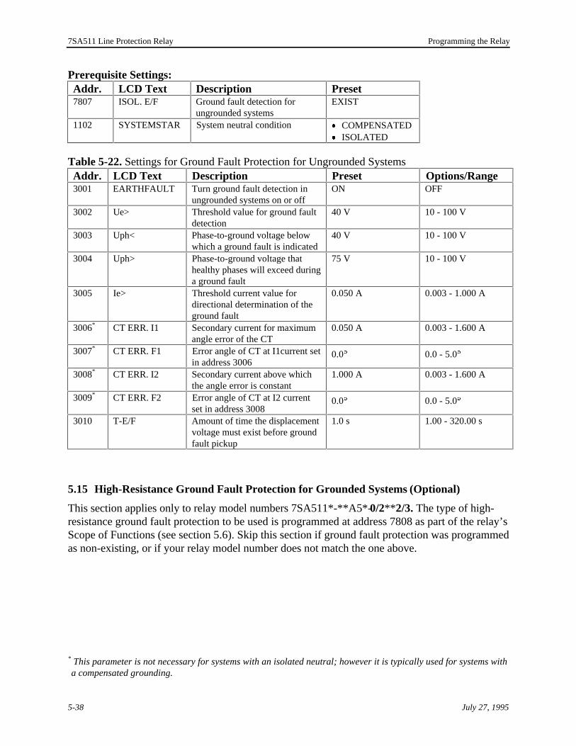
7SA511 Line Protection Relay Programming the Relay
relay’smed
s with
Prerequisite Settings:Addr. LCD Text Description Preset7807 ISOL. E/F Ground fault detection for
ungrounded systemsEXIST
1102 SYSTEMSTAR System neutral condition · COMPENSATED· ISOLATED
Table 5-22. Settings for Ground Fault Protection for Ungrounded SystemsAddr. LCD Text Description Preset Options/Range3001 EARTHFAULT Turn ground fault detection in
ungrounded systems on or offON OFF
3002 Ue> Threshold value for ground faultdetection
40 V 10 - 100 V
3003 Uph< Phase-to-ground voltage belowwhich a ground fault is indicated
40 V 10 - 100 V
3004 Uph> Phase-to-ground voltage thathealthy phases will exceed duringa ground fault
75 V 10 - 100 V
3005 Ie> Threshold current value fordirectional determination of theground fault
0.050 A 0.003 - 1.000 A
3006* CT ERR. I1 Secondary current for maximumangle error of the CT
0.050 A 0.003 - 1.600 A
3007* CT ERR. F1 Error angle of CT at I1current setin address 3006
0.0° 0.0 - 5.0°
3008* CT ERR. I2 Secondary current above whichthe angle error is constant
1.000 A 0.003 - 1.600 A
3009* CT ERR. F2 Error angle of CT at I2 currentset in address 3008
0.0° 0.0 - 5.0°
3010 T-E/F Amount of time the displacementvoltage must exist before groundfault pickup
1.0 s 1.00 - 320.00 s
5.15 High-Resistance Ground Fault Protection for Grounded Systems (Optional)
This section applies only to relay model numbers 7SA511*-**A5*-0/2** 2/3. The type of high-resistance ground fault protection to be used is programmed at address 7808 as part of the Scope of Functions (see section 5.6). Skip this section if ground fault protection was programas non-existing, or if your relay model number does not match the one above.
* This parameter is not necessary for systems with an isolated neutral; however it is typically used for systema compensated grounding.
July 27, 19955-38

7SA511 Line Protection Relay Chapter 5
in this
nt.
ress
type
erence
matic relay
etersailable.e whiched all ofttings.
Each type of high-resistance ground fault protection, listed below, is discussed separatelysection.
· Directional, definite time overcurrent protection with nondirectional backup elemeThe settings for this type of protection are in address block 3100.
· Directional, definite time overcurrent protection with directional comparison andnondirectional backup element. The settings for this type of protection are in addblocks 3100 and 3200.
· Nondirectional, inverse time overcurrent protection element. The settings for thisof protection are in address block 3300.
The various high-resistance ground fault protection methods are described in detail in RefA, “Method of Operation.”
High-resistance ground fault protection for grounded systems can also work with the autoreclose function, when available. Refer to section 5.16 for information on programming thefor automatic reclose operations with high-resistance ground fault protection.
5.15.1 Directional Protection With Nondirectional Backup (3100)For directional, definite time overcurrent protection with nondirectional backup, the paramare set in address block 3100. Table 5-23 lists the relay presettings and setting options avCompare these presettings to the information on the completed worksheets and determinsettings you need to change to match your operating environment. When you have changthe necessary settings, follow the procedure described in section 5.3.4 to save the new se
Prerequisite Settings:Addr. LCD Text Description Setting7808 EARTH FAULT Type of ground fault protection DIRECTIONAL D.T.1102 SYSTEMSTAR System neutral condition SOLIDLY EARTHED
July 27, 1995 5-39

7SA511 Line Protection Relay Programming the Relay
l
and in 3200.
gs tonge tollow
Table 5-23. Settings for Directional, Definite Time Overcurrent Protection With NondirectionaBackup ElementAddr. LCD Text Description Preset Options/Range3101 E/F D.T. Turn the ground fault definite
time protection on or offON OFF
3103 Ie> Pickup value for groundcurrent detection
0.20 I/In 0.10 - 1.00 I/In
3104 Ue> Minimum displacement voltagerequired for directionaldetermination
5.0 V 1.0 - 10.0 V
3106 T-DIRECT. Trip delay for directionalelement
0.90 s · 0.00 - 32.00 s
· ¥
3107 DIRECTION Direction used for directionaldetermination
FORWARDS · REVERSE· NON-
DIRECTIONAL3108 T-NON-DIR. Trip delay time for
nondirectional backup element1.20 s · 0.00 - 32.00 s
· ¥
3109 T-BLOCK Time duration during whichground fault protection isblocked when distanceprotection has picked up
1.30 s 0.00 - 320.00 s
5.15.2 Directional Comparison Protection With Nondirectional Backup (3200)For directional, definite time overcurrent protection with directional comparison andnondirectional backup, the parameters are set in address block 3100, as discussed above, address block 3200. The parameters for the echo keying function are also in address block
Table 5-24 lists the relay presettings and setting options available. Compare these presettinthe information on the completed worksheets and determine which settings you need to chamatch your operating environment. When you have changed all of the necessary settings, fothe procedure described in section 5.3.4 to save the new settings.
Prerequisite Settings:Addr. LCD Text Description Setting7808 EARTH FAULT Type of earth (ground) fault
protectionDIREC.COMPARISON
1102 SYSTEMSTAR System neutral condition SOLIDLY EARTHED3100block
(See Table 5-23 above.)
July 27, 19955-40

7SA511 Line Protection Relay Chapter 5
lock
u
.
Table 5-24. Settings for Directional, Definite Time Overcurrent Protection with DirectionalComparison and Nondirectional Backup ElementAddr. LCD Text Description Preset Options/Range3105 T-DELAY Delay time for transmission and trip 0.00 s · 0.00 - 32.00 s
· ¥
3201 E/F COMPAR Turn the ground fault definite time,directional comparison protection onor off
ON OFF
3203 T-TRANSBLO Transient blocking time, which mustbe longer than the transmission time
0.05 s 0.01 - 32.00 s
3204 T-WAIT TB Waiting time before initiatingtransient blocking with missingreception signal
¥ s · 0.00 - 32.00 s
· ¥
3210 E/F ECHO Turn the echo keying function on oroff
ON OFF
3211 T-ECHO-DEL Echo time delay 0.20 s · 0.01 - 32.00 s
· ¥
3212 T-ECHO-IMP Duration of echo impulse 0.05 s 0.02 - 32.00 s3213 T-ECHO-BLO Echo blocking time 0.40 s 0.01 - 32.00 s
5.15.3 Nondirectional, Inverse Time Overcurrent Protection (3300)For nondirectional, inverse time overcurrent protection, the parameters are set in address b3300. Table 5-25 lists the relay presettings and setting options available. Compare thesepresettings to the information on the completed worksheets and determine which settings yoneed to change to match your operating environment. When you have changed all of thenecessary settings, follow the procedure described in section 5.3.4 to save the new settings
Prerequisite Settings:Addr. LCD Text Description Preset7808 EARTH FAULT Type of earth (ground) fault protectionINVERSE TIME1102 SYSTEMSTAR System neutral condition SOLIDLY
EARTHED
Table 5-25. Settings for Nondirectional Inverse Time Overcurrent ProtectionAddr. LCD Text Description Preset Options/Range3301 E/F I.T. Turn the nondirectional, inverse time
ground fault protection on or offON OFF
3302 E/F CHARAC Select inverse time characteristic NORMALINVERSE
· VERY INVERSE· EXTREMELY
INVERS3303 Ie> Pickup ground current value 0.20 I/In 0.10 - 4.00 I/In3304 TIe> Trip delay time dial (multiplier) 0.50 s · 0.00 - 32.00 s
· ¥
3305 T-BLOCK Time during which ground faultprotection is blocked when distanceprotection has picked up
1.30 s 0.00 - 320.00 s
July 27, 1995 5-41

7SA511 Line Protection Relay Programming the Relay
on,sn
odelle-
able
w the
in the
vice and you to save
5.16 Automatic Reclose (Optional)
This section applies only to relays equipped with the optional automatic reclose (AR) functimodel numbers 7SA511*-**A5*-**B/C/F/G*. Skip this section if your relay does not have thifunction. Automatic reclose is effective only if configured as existing at address 7810 (see sectio5.6).
The relay can be ordered either with three-pole automatic reclose (single- and multi-shot, m7SA511*-**A5*- ** B/F*) or for all modes of automatic reclose (single-pole, three-pole, singand three-pole, single- and multi-shot, model 7SA511*-**A5*-**C/G*). If the relay modelconfiguration is for three-pole automatic reclose only, then only those parameters are availwhich relate to this automatic reclose program.
There are two address blocks used to configure automatic reclose.
· The device configuration parameters in address block 7900 include settings for hoautomatic reclose function works with other relay protection functions.
· Address block 3400 consists of the specific settings required for automatic reclose7SA511 relay.
Prerequisite Setting:Addr. LCD Text Description Setting7810 INTERNAL AR Internal automatic reclose function EXIST
5.16.1 Device Configuration for Automatic Reclose (7900)Table 5-26 lists the relay presettings and setting options available for automatic reclose deconfiguration. Compare these presettings to the information on the completed worksheetsdetermine which settings you need to change to match your operating environment. Whenhave changed all of the necessary settings, follow the procedure described in section 5.3.4the new settings.
Table 5-26. Device Configuration Automatic Reclose SettingsAddr. LCD Text Description Preset Option7902 AR w/ DIST. Indicates whether or not automatic
reclose works with distance protectionYES NO
7903 AR w/ O/C Indicates whether or not automaticreclose works with emergencyovercurrent protection
YES NO
7904 AR w/o TELE Indicates if automatic reclose workswhen signal transmission is distortedor switched off
YES NO
7906 AR w/ E/F Indicates if automatic reclose workswith ground fault protection ingrounded systems
YES NO
July 27, 19955-42

7SA511 Line Protection Relay Chapter 5
d out
you to save
Note: Address number 7910 indicates how the circuit breaker test via binary input is carrieand is discussed, therefore, in Chapter 7 “Commissioning the Relay.”
5.16.2 Automatic Reclose Function Settings (3400)Table 5-27 lists the relay presettings and the setting options available for automatic recloseoperation. Compare these presettings to the information on the completed worksheets anddetermine which settings you need to change to match your operating environment. Whenhave changed all of the necessary settings, follow the procedure described in section 5.3.4the new settings.
Terminology:RAR Rapid Automatic Reclose, or first AR cycleDAR Delayed Automatic Reclose, or further cycles (shots), after the first
Table 5-27. Automatic Reclose Function SettingsAddr. LCD Text Description Preset Options/Range3401 AR FUNCT Turn the automatic reclose function on
or offON OFF
3402 AR BLO REV Indicate whether or not automaticreclose will be blocked when a fault inthe reverse direction is tripped
YES NO
3405 T-RECLAIM Reclaim time after the AR cycle 3.00 s 0.50 - 320.00 s3406 T-CLOSE Set the maximum duration of the
closing command1.00 s 0.01 - 320.00 s
3407 T-MAN. CLOS Reclaim time after the circuit breaker ismanually closed
1.00 s 0.50 - 320.00 s
3412 RAR PROG. Select the automatic reclose programfor the first reclose cycle (RAR)—thissetting is dependent on the relay model
THREE-POLE · SINGLE-POLE·
SINGLE/THREE-POL
3413 RAR ZONE Select the distance protection zone tobe used for the RAR cycle
Z1B Z1
3414 RAR T-ACT. Action time for the RAR (first AR)cycle—if trip signal is issued after thistime period, the AR function is blocked
0.20 s 0.01 - 320.00 s
3415 RAR T-3POL Dead time for a three-pole RAR cycle,0.50 s 0.01 - 320.00 s3416 RAR T-1POL Dead time for a single-pole RAR cycle,1.20 s 0.01 - 320.00 s3418* EV. F. RECOG Select how evolving faults are
recognized (applicable only to singlepole AR)
BY FAULTDETEC.
BY TRIPCOMMAND
3419* EV. F. BLOCK Select how evolving faults are handled- always blocked; never blocked;blocked after the time period set inaddress 3420
ALWAYS · NEVER· >T-DISCR.
3420* T-DISCR. Discrimination time for evolving faultswhen address 3419 is set to >T-DISCR.
0.10 s 0.01 - 320.00 s
July 27, 1995 5-43
* This parameter is only used with single-pole reclose.

7SA511 Line Protection Relay Programming the Relay
hece-e
parengs
.
yence
Addr. LCD Text Description Preset Options/Range3432 DAR PROG. Select DAR program - only after an
unsuccessful RAR cycle; without priorRAR; no DAR
DAR AFTERRAR
· DAR WITHOUTRAR
· WITHOUT DAR3433 DAR SHOTS Number of permissible DAR cycles
(does not include the RAR)0 0 - 9
3434 DAR BLOCK Specify Z1 trip delay when DAR isblocked
Z1: T1 Z1: T1B
3435 DAR T-ACT. Action time for DAR 0.20 s 0.01 - 320.00 s3436 DAR T-3POL Dead time for DAR 0.80 s 0.01 - 320.00 s
5.17 Fault Location Settings (3800)
Address block 3800 consists of the settings required for determining the location of a fault. Tsettings include selecting how fault location is initiated, the length of the line, and the reactanper-unit-length. For relays equipped with parallel line compensation (model number 7SA511***A5*- 2***), you also indicate at address 3805 that parallel line compensation is effective. SeReference E, “Setting Calculations,” for detailed information on determining the fault locationsettings and for the prerequisites required for the parallel line compensation application.
Table 5-28 lists the relay presettings and the setting options available for fault location. Comthese presettings to the information on the completed worksheets and determine which settiyou need to change to match your operating environment. When you have changed all of thenecessary settings, follow the procedure described in section 5.3.4 to save the new settings
Prerequisite Setting:Addr. LCD Text Description Setting7805 FAULT LOCAT. Fault location function EXIST
Table 5-28. Fault Location SettingsAddr. LCD Text Description Preset Options/Range3802 START Select how fault location is initiated TRIP
COMMANDDROP-OFF or TRIP
3803* X SEC Reactance value of the line, per unitline length, as a secondary valuerelated to 1 A.
0.500 W/km 0.010 - 5.000 W/km
3804* LINE LENGTH Total length of the line 100.00 km 1.00 - 550.00 km3805 PARAL.LINE Indicate whether or not parallel line
compensation is effectiveNO YES
* Although the LCD will always display the unit of length as kilometers, the per-unit-length values mabe specified as miles as long as both parameters(3803 and 3804) are specified consistently. ReferE, “Setting Calculations” provides details on calculating secondary values from primary values.
July 27, 19955-44

7SA511 Line Protection Relay Chapter 5
y toition to
r via
ificheing
ich
heon/off
5.18 Turning the Relay Functions On and Off
As discussed in section 5.6, “Relay Scope of Functions (7800),” you must program the relarecognize the various operating and protection functions as existing or non-existing. In addthose settings, the 7SA511 relay allows certain functions to be turned on or off manually obinary inputs.
With the relay operating, for example, you may need to turn a function on or off under specconditions such as turning off the pilot protection function during maintenance or repair of ttransmission medium, or turning off the automatic reclose system when a transfer bus is beused.
Table 5-29 identifies all of the On/Off functions available in the 7SA511 relay and shows whsection of this manual discusses the actual function.
Table 5-29. Relay Functions that can be Turned On and Off.Addr. LCD Text Function See Section1201 DIST.PROT. Distance protection 5.102101 PUTT MODE Permissive underreach transfer trip mode for distance
protection5.12.1
2201 POTT MODE Permissive overreach transfer trip mode for distanceprotection—when turned off, echo keying function (2220) isalso turned off
5.12.2
2220 ECHO Echo keying function for pilot protection with distanceprotection—this is turned off if POTT mode (2201) is turnedoff
5.12.2
2601 EMERG. O/C Emergency overcurrent protection 5.132801 FAULT REC. Waveform capture 5.52910 FUSE-FAIL Fuse failure monitor 5.9.23001 EARTH FAULT Ground fault detection for ungrounded systems 5.143101 E/F D.T. High-resistance ground fault protection for grounded
systems—directional, definite time with nondirectionalbackup element
5.15.1
3201 E/F COMPAR Directional comparison ground fault protection for groundedsystems—this function is turned off with high-resistanceground fault, directional definite time protection (3101)
5.15.2
3210 E/F ECHO Echo keying function for directional comparison ground faultprotection—this function is turned off with high-resistanceground fault, directional definite time protection (3101)
5.15.2
3301 E/F I.T. High-resistance ground fault protection for groundedsystems—nondirectional, inverse time element
5.15.3
3401 AR FUNCT Internal automatic reclose function 5.16.2
On/off control may be accomplished through the operator panel, the front serial port, and tbinary inputs. Refer to Reference E, “Setting Calculations” for detailed information on how control works and how binary inputs must be configured to turn functions on and off.
July 27, 1995 5-45

7SA511 Line Protection Relay Programming the Relay
ethree
eset
unit in
.
sword
ber ino the
5.19 Configuration Settings (6000)
The configuration settings tell the relay what action to take and how. Configuration is the processof assigning one or more logical functions to each of the physical input/output (I/O) units. Threlay has a large number of predefined logical functions. Each logical function has a unique digit function number (FNo) assigned to it. A complete list of logical functions that can beconfigured is provided in Reference G, “Input/Output Functions,” in function number order.
If you change any of the configuration settings, the relay microprocessor will automatically rand restart after the new settings are saved.
5.19.1 Procedure for Configuring the Logical FunctionsTo make configuration changes, the relay must be placed in programming mode using thepassword as described in section 5.3.2. Follow this example procedure to configure an I/O the 7SA511 relay.
Note: There are two qualifiers on the functions assigned to for binary inputs (NO andNC) and LED indicators (n and nm). Refer to sections 5.19.3 and 5.19.5,respectively, for further instructions on selecting the correct mode of operation
1. Select the address number of the I/O unit you want to configure and enter the relay pas(see section 5.3.2). The display will appear similar to this example, which shows addressnumber 6204.
6 2 0 4 zz S I G N A L
R E L A Y 4
2. Press the F key. An “F” will display over the solid bar following the address number in thedisplay.
3. Press the key to complete the change to the function selection level. The address numthe display is replaced with a 3 digit index number 001, which is automatically assigned tfirst function. As shown in the example below, the second line of the display contains anabbreviated description of the assigned function.
0 0 1 zz R E L A Y 4
> V T m c b T r i p
July 27, 19955-46

7SA511 Line Protection Relay Chapter 5
ing
ple
dexot
4. There are two ways to assign a function to an I/O unit.
(1) Entering the function number.a. Enter the function number (FNo) using the numeric keys. The function number be
entered displays in line 2 as shown in the example below.
0 0 1 zz R E L A Y 4
1 2 1
b. Press Enter. The description of the function displays in line 2 as shown in the exambelow.
0 0 1 zz R E L A Y 4
F A I L U R E 2 4 V
c. Save the new setting(s) as instructed in section 5.3.4.
(2) Scrolling through the list of available functions using the No and Back Space keys.a. Repeatedly press the No key to page forward, or the Back Space key to page
backward, until the description of the function you want is displayed (see exampledisplay in Step 1.b above).
b. Press Enter.c. Save the new setting(s) as instructed in section 5.3.4.
5. Press the key to go to the index number sequence. The next function assignment willdisplay with index number 002 as shown below.
0 0 2 zz R E L A Y 4
F A I L U R E SS I
6. Press the or key to page up and down through the index number sequence. If an innumber is accessed for which no function has been assigned, the second line displays “nallocated” as shown below.
0 1 0 zz R E L A Y 4
n o t a l l o c a t e d
July 27, 1995 5-47

7SA511 Line Protection Relay Programming the Relay
thesee.
nction
5.19.2 PresettingsTable 5-30 below identifies the configuration presettings for each of the I/O units. Comparesettings to the data on the completed worksheets to see which settings you need to chang
Table 5-30. Configuration Presettings.Addr. I/O Unit Index No. LCD Text (2nd line) FNo6101 Binary Input 1 001 >Reset LED NO 0066102 Binary Input 2 001 >VT mcb Trip NO 0146103 Binary Input 3 001 >CB Aux. Cont NO 0126104 Binary Input 4 001 >Manual Close NO 0116105 Binary Input 5 001 >Dist. Recept NO 0826106 Binary Input 6 001 >Dist. RecFail NO 0816107* Binary Input 7 001 >CB ready NO 0746108* Binary Input 8 001 >AR block NO 0716109* Binary Input 9 001 >AR ON NO 0416110* Binary Input 10 001 >AR OFF NO 0426201 Signal Relay 1 001 Dist. Send 5716202* Signal Relay 2 001 AR inoperativ 8056203* Signal Relay 3 001 CB Alarm Supp 8356204 Signal Relay 4 001 >VT mcb Trip 014
002 Failure SI 151
003 Failure SUp-e 152
004 Failure SUp-p 153
005 Failure Isymm 154006 Failure Usymm 155007 Failure Umeas 156008 Fuse-Failure 157009 Fail.PhaseSeq 159
6205 Signal Relay 5 001 Dev. operative 1016206 Signal Relay 6 001 Device Trip 2516207 Signal Relay 7 001 Dist.Fault L1 352
002 O/C Fault L1 6236208 Signal Relay 8 001 Dist.Fault L2 353
002 O/C Fault L2 6246209 Signal Relay 9 001 Dist.Fault L3 354
002 O/C Fault L3 6256210 Signal Relay 10 001 Dist.EarthFlt 355
002 O/C Fault E 6266211 Signal Relay 11 001 Reverse Direc 357
*This preset configuration is only true when the relay has the internal automatic reclose function and the fuis programmed as existing under address 7810.
July 27, 19955-48
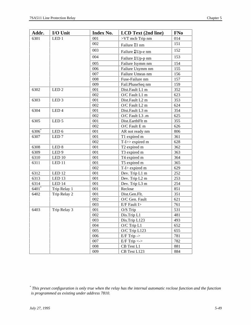
7SA511 Line Protection Relay Chapter 5
ction
Addr. I/O Unit Index No. LCD Text (2nd line) FNo6301 LED 1 001 >VT mcb Trip nm 014
002 Failure SI nm 151
003 Failure SUp-e nm 152
004 Failure SUp-p nm 153
005 Failure Isymm nm 154006 Failure Usymm nm 155007 Failure Umeas nm 156008 Fuse-Failure nm 157009 Fail.PhaseSeq nm 159
6302 LED 2 001 Dist.Fault L1 m 352002 O/C Fault L1 m 623
6303 LED 3 001 Dist.Fault L2 m 353002 O/C Fault L2 m 624
6304 LED 4 001 Dist.Fault L3 m 354002 O/C Fault L3 .m 625
6305 LED 5 001 Dist.EarthFlt m 355002 O/C Fault E m 626
6306* LED 6 001 AR not ready nm 8066307 LED 7 001 T1 expired m 361
002 T-I>> expired m 6286308 LED 8 001 T2 expired m 3626309 LED 9 001 T3 expired m 3636310 LED 10 001 T4 expired m 3646311 LED 11 001 T5 expired m 365
002 T-I> expired m 6296312 LED 12 001 Dev. Trip L1 m 2526313 LED 13 001 Dev. Trip L2 m 2536314 LED 14 001 Dev. Trip L3 m 2546401* Trip Relay 1 001 Reclose 8516402 Trip Relay 2 001 Dist.Gen.Flt. 351
002 O/C Gen. Fault 621003 E/F Fault I> 761
6403 Trip Relay 3 001 O/S Trip 531002 Dis.Trip L1 481003 Dis.Trip L123 493004 O/C Trip L1 652005 O/C Trip L123 655006 E/F Trip -> 781007 E/F Trip <-> 782008 CB Test L1 881009 CB Test L123 884
* This preset configuration is only true when the relay has the internal automatic reclose function and the funis programmed as existing under address 7810.
July 27, 1995 5-49

7SA511 Line Protection Relay Programming the Relay
y hashe
allyly.
d
Addr. I/O Unit Index No. LCD Text (2nd line) FNo6404 Trip Relay 4 001 O/S Trip 531
002 Dis.Trip L2 483003 Dis.Trip L123 493004 O/C Trip L2 653005 O/C Trip L123 655006 E/F Trip -> 781007 E/F Trip <-> 782008 CB Test L2 882009 CB Test L123 884
6405 Trip Relay 5 001 O/S Trip 531002 Dis.Trip L3 487003 Dis.Trip L123 493004 O/C Trip L3 654005 O/C Trip L123 655006 E/F Trip -> 781007 E/F Trip <-> 782008 CB Test L3 883009 CB Test L123 884
Note: The presets for Binary Inputs 5 and 6, and Signal Relay 1 implement the pilotprotection interface.
5.19.3 Binary Inputs (6100)The configuration settings for the binary inputs are in address block 6100. The 7SA511 relaten binary inputs. Up to 10 logical functions can be assigned to each binary input. Refer to tcompleted worksheets to see if you need to change a binary input function.
For each input function, you can specify whether the function will operate in the Normally Open(NO) or Normally Closed (NC) mode. All preset input assignments are set to operate in NormOpen mode, which means a voltage applied to the input terminals activates the function. NormalClosed mode means a normally present voltage removed from the terminals activates the function
When paging through the available functions in the selection level using the No or Back Spacekeys, the abbreviated description shown in the LCD is followed by an NO or NC indication, whichchanges from one to the other when the No or Back Space key is pressed. In this way, the desiremode can be selected when the paging method is used.
When entering the function number directly, the function number can be extended by a 0 or 1where
.0 indicates normally open (NO) mode
.1 indicates normally closed (NC) mode
If the extension is omitted, the function display defaults to NO. This can be changed to NC bypressing the No or Backspace key then pressing Enter to select.
July 27, 19955-50

7SA511 Line Protection Relay Chapter 5
able
D
or
sed.
Up toto see if
5.19.4 Signal Relays (6200)The signal relays are configured in address block 6200. The 7SA511 relay has 11 programmsignal relays. Up to 20 logical functions can be assigned to each signal relay. Refer to thecompleted worksheets to see if you need to change a signal relay function.
5.19.5 LED Indicators (6300)The LED indicators are configured in address block 6300. The 7SA511 relay has 14programmable LEDs. Up to 20 logical functions can be assigned to each programmable LEindicator. Refer to the completed worksheets to see if you need to change a LED function.
For each LED function, you can specify whether the function will operate in the latched (m) unlatched (nm) mode.
When paging through the available functions in the selection level using the No or Back Spacekeys, the abbreviated description shown in the LCD is followed by an m (for memorized) or nm(for not memorized) indication, which changes from one to the other when the No or Back Spacekey is pressed. In this way, the desired mode can be selected when the paging method is u
When entering the function number directly, the function number can be extended by a 0 or 1where
.0 indicates unlatched (nm) mode
.1 indicates latched (m) mode
If the extension is omitted, the function display defaults to nm. This can be changed to m bypressing the No or Backspace key then pressing Enter to select.
5.19.6 Trip Relays (6400)The trip relays are configured in address block 6400. The 7SA511 relay has five trip relays.10 logical functions can be assigned to each trip relay. Refer to the completed worksheets you need to change a trip relay function.
July 27, 1995 5-51

7SA511 Line Protection Relay Programming the Relay
July 27, 19955-52
This page intentionally blank

7SA511 Line Protection Relay Chapter 6
July 27, 1995 6-1
Displaying System and Relay Information
Table of Contents
6. Displaying System and Relay Information.............................................................................6-36.1 Using the Operator Panel to Display Information............................................................6-36.2 Event Log (5100)...........................................................................................................6-4
6.2.1 Storage and Display Description..............................................................................6-56.2.2 Event Log Messages................................................................................................6-5
6.3 Target Log for All Systems (5200, 5300, and 5400) .......................................................6-86.3.1 Storage and Display Description..............................................................................6-86.3.2 Example System Fault Messages..............................................................................6-96.3.3 Target Log Messages ............................................................................................6-11
6.4 Data Log for Ground Faults in Ungrounded Systems (5500) (Optional)........................6-136.4.1 Storage and Display Description............................................................................6-136.4.2 Isolated Ground Fault Data Log Messages.............................................................6-14
6.5 Circuit Breaker Operation Statistics (5600) ..................................................................6-146.6 Reading the Measured Values.......................................................................................6-15
6.6.1 Operational Measured Values (5700).....................................................................6-156.6.2 Ground Fault Measured Values in Ungrounded Systems (5800) (Optional)............6-16
6.7 Waveform Capture.......................................................................................................6-17
List of Figures
Figure 6-1. Waveform Capture Display Example...................................................................6-18

7SA511 Line Protection Relay Displaying System and Relay Information
July 27, 19956-2
This page intentionally blank

7SA511 Line Protection Relay Chapter 6
ean
ofed
elay
formodelorm
5000.ys to
6. Displaying System and Relay Information
This chapter describes the system and relay information available and tells you how to use threlay’s operator panel to display the information. When prompted, the operator panel LCD cdisplay the following information:
· Event log for the relay during normal and fault conditions· Target log for the last three network faults· Target log for the last three ground faults in ungrounded systems· Measured values of the protected system (in grounded and ungrounded systems)· Circuit breaker operation statistics
The system and relay information is also accessible using analysis software if the relay isconnected to a PC through the front port. In addition, you can also display actual waveformsthe last fault record when DIGSI® analysis software is used on a PC and the relay is programmfor waveform capture (see section 5.5).
Table 6-1 lists the address blocks and descriptions that are used to display the system and rinformation. The relay password is not required to display relay data.
Table 6-1. Address Blocks Used to Display System and Relay Information.Addr. Description5100 Event log. The relay stores the last 50 messages that displayed.5200 Target history for the last (most recent) fault.5300 Target history for the second to last fault.5400 Target history for the third to last fault.5500 Ground fault target history for relay models with ground fault detection for
ungrounded systems (model number 7SA511*-**A5*-1***).5600 Circuit breaker operation statistics.5700 Measured phase and neutral currents, voltages, and apparent power of the
protected system.5800 Ground fault measured values for relay models with ground fault detection for
ungrounded systems (model number 7SA511*-**A5*-1***).
The tables in this chapter identify, by address block, all of the messages and values availabledisplay on the LCD. Whether or not some information can be displayed is dependent on the and configuration of the individual relay. The last section in this chapter discusses the wavefcapture feature.
6.1 Using the Operator Panel to Display Information
All of the messages available for display in the operator panel LCD are within address block Press the Event key to go directly to address block 5000. You can then use the navigation ke
July 27, 1995 6-3

7SA511 Line Protection Relay Displaying System and Relay Information
ccurs.anual.
e. is
lein
ctive.
address. Eventandational
go to address blocks 5100, 5200, etc. You may also use the Direct Addr. key to view any logaddress.
5 0 0 0 zz
A N N U N C I A T I O N S
Annunciation refers to the process of activating the various relay outputs when an event oMessages that appear on the operator panel LCD are also called annunciations in this m
The following procedure uses the Event key and the navigation keys to access and displayinformation. Refer to section 5.3.1, “Selecting an Address,” for information on using the Direct
Addr key to access information.
To display the information you want to review, follow this procedure:
1. Press the Event key. Address block 5000 appears in the display as shown abov2. Press the key until the address block of annunciations that you want to review
displayed as shown in the example below:
5 1 0 0 zz O P E R A T I O N A L
A N N U N C I A T I O N S
3. Press the key to display the first entry in the list you are viewing. The exampbelow shows how the event log message appears when the relay is operating emergency overcurrent mode.
1 1 / 0 2 / 9 4 0 9 : 0 3
E m e r g . M o d e : C
4. Press the or key to move up or down in the list you are viewing.5. When you are finished reading the information, press the or key to go to
another address block. Information is not updated when the address block is a
6.2 Event Log (5100)
The Event Log consists of operational and status messages chronologically listed under 5100, starting with the most recent message. Table 6-2 identifies the available messageslog messages include pickup and drop-out of enabled protections and alarms, activation deactivation of binary inputs, signal outputs, trips, relay diagnostics, and other relay operinformation.
July 27, 19956-4

7SA511 Line Protection Relay Chapter 6
storede last
ventlaced in the
(see
thg
ay. See
6.2.1 Storage and Display DescriptionUp to 50 messages can be stored in the event log. After all 50 memory locations are filled,additional messages replace the oldest messages in sequence. When paging through the messages, if more than 50 messages have been stored, “Table overflow” is displayed in thmessage slot. Otherwise, “End of table” will appear as the last valid message.
For event log messages, the first line of the display always gives the date and time of the e(see example below). The time is given to the nearest minute, but the events are sorted (pthe order of occurrence) with 1 millisecond resolution. The second line of the display givesevent description as listed in Table 6-2. Each event description may be followed by a C or G tag.The C tag (Coming) indicates the message was logged at pickup (see example below). TheG tag(Going) indicates the message was logged at drop-out.
1 1 / 0 2 / 9 4 1 1 : 1 5
P a r a m . S e t C : C
6.2.2 Event Log MessagesThe operational and status messages in the event log fall into four different categories.
1. Binary Inputs - events associated with changes on the binary inputs.2. General - operational events not associated with another specific category.3. Monitoring functions - events associated with the internal relay monitoring functions
Reference B, “Hardware & Software”).4. Relay protection functions and optional features - operational events associated wi
distance protection, pilot protection, emergency overcurrent protection, power swinblock/trip, high-resistance ground fault protection, and automatic reclose functions.
Only messages consistent with your relay configuration and options will appear in the displChapter 8, “Maintenance,” for information on how to erase messages in the event log.
Table 6-2. Possible Event Log MessagesLCD Text (2nd line) Description Possible TagBinary Inputs>Start FltRec Start waveform capture from external command via binary input C/G>Start FltLoc Start fault location from external command via binary input C/G>VT mcb Trip Voltage transformer secondary m.c.b. has tripped C/G>Annunc. 1 User-defined annunciation 1 has been received C/G>Annunc. 2 User-defined annunciation 2 has been received C/G>Annunc. 3 User-defined annunciation 3 has been received C/G>Annunc. 4 User-defined annunciation 4 has been received C/G>Start AR Start internal automatic reclose C>Trip L1 AR Trip pole 1 via internal automatic reclose C>Trip L2 AR Trip pole 2, via internal automatic reclose C>Trip L3 AR Trip pole 3 via internal automatic reclose C>Extens. Z1B Change distance measurement to overreach zone Z1B C
July 27, 1995 6-5

7SA511 Line Protection Relay Displaying System and Relay Information
LCD Text (2nd line) Description Possible Tag>1pole Trip External automatic reclose device is ready for single-pole trip C>1pole only External automatic reclose device is ready for single-pole
reclose onlyC/G
>I>> block High-set (I>>) element of emergency overcurrent protection isblocked
C
>DAR block. Delayed automatic reclose (DAR, 2nd and further shots) isblocked
C/G
>Dist. RecFail Carrier reception for pilot protection with distance protection isfaulty
C/G
>Dist. Recept Carrier signal for pilot protection with distance protection hasbeen received
C
>E/F Rec. Fail Carrier reception for directional comparison ground faultprotection is faulty
C/G
>E/F Recept Carrier signal for directional comparison ground faultprotection has been received
C
GeneralRe-start Microprocessor has been reset and restarted CSystemFlt A system fault has been detected—see detailed information in
the appropriate target log (address blocks 5200, 5300, and 5400)C
E/F Detec In ungrounded systems, a ground fault has been detected—seedetailed information under address 5500, “ISOLATED EARTHFLT DATA”
C/G
LED reset Stored LED indications have been reset CFlt. Rec. OFF Waveform capture is turned off C/GParam.Running Parameters are being set, i.e., the relay is in programming mode C/GManual Close Circuit breaker has been manually closed CCB in Test Circuit breaker test is in progress C/GParam. Set A Parameter set A is active C/GParam. Set B Parameter set B is active C/GParam. Set C Parameter set C is active C/GParam. Set D Parameter set D is active C/G
Monitoring FunctionsFailure 24V Failure in 24 volt internal power supply C/GFailure 15V Failure in 15 volt internal power supply C/GFailure 5V Failure in 5 volt internal power supply C/GFailure 0V Failure in 0 volt internal offset for A/D converters C/GFailure GEA Failure in basic input/output module GEA C/GFailure ZEA Failure in additional input/output module ZEA C/GAnnunc. Lost A message table has overflowed CFlt.Buff.Over Fault message table has overflowed CE/F Buff.Over Fault message table for ground fault detection in ungrounded
systems has overflowedC
Flt.Flag Over Fault flag buffer has overflowed COper.Ann.Inva Operational messages are invalid C/GFlt.Ann.Inval Fault messages are invalid C/GE/F Prot.Inva Messages for ground fault detection in ungrounded systems are
invalidC/G
Stat.Buff.Inv Circuit breaker operation statistics are invalid C/GLED Buff.Inva Stored LED indications are invalid C/G
July 27, 19956-6

7SA511 Line Protection Relay Chapter 6
LCD Text (2nd line) Description Possible TagFailure SI Failure detected by measured current sum monitor C/G
Failure SUp-e Failure detected by measured voltage sum monitor, phase-ground voltage
C/G
Failure SUp-p Failure detected by measured voltage sum monitor, phase-phasevoltage
C/G
Failure Isymm Failure detected by measured current symmetry monitor C/GFailure Usymm Failure detected by measured voltage symmetry monitor C/GFailure Umeas Loss of measured voltages C/GFFM pick-up Fuse failure monitor has picked up C/GFail. PhaseSeq Failure detected by phase sequence monitor C/GChs.Error Check sum error detected in memory C/GChs.S1 Error Check sum error detected in parameter set A—operation with
this set is not possibleC/G
Chs.S2 Error Check sum error detected in parameter set B—operation withthis set is not possible
C/G
Chs.S3 Error Check sum error detected in parameter set C—operation withthis set is not possible
C/G
Chs.S4 Error Check sum error detected in parameter set D—operation withthis set is not possible
C/G
Distance Protection, Pilot Protection, & Emergency Overcurrent ProtectionDist. Off Distance protection is turned off C/GDist. blocked Distance protection is blocked C/GTele off Pilot protection function with distance protection is turned off C/GDist.Rec.Flt Reception signal for pilot protection with distance protection is
faultyC/G
Dist. Echo Echo signal for pilot protection with distance protection hasbeen transmitted
C
Emerg. Mode Emergency overcurrent protection mode is effective; therefore,distance protection is ineffective
C/G
Power Swing FunctionPower Swing A power swing is detected C/GO/S Trip An out-of-step trip signal due to power swing detection has been
issuedC
Ground Fault ProtectionE/F Prot. off For grounded systems, ground fault protection is turned off C/GE/F Echo For grounded systems, echo signal for directional comparison
ground fault protection has been transmittedC
>E/F Rec. Fail For grounded systems, reception signal for directionalcomparison ground fault protection is faulty
C/G
E/F det. OFF For ungrounded systems, ground fault detection is turned off C/G
Automatic Reclose FunctionAR off Automatic reclose function is turned off C/GAR inoperativ Automatic reclose cannot be initiated C/G
Circuit Breaker Test FunctionCB Test L1 Trip single-pole 1 by internal CB test function CCB Test L2 Trip single-pole 2 by internal CB test function CCB Test L3 Trip single-pole 3 by internal CB test function CCB Test L123 Trip three-pole has occurred by internal CB test function C
July 27, 1995 6-7

7SA511 Line Protection Relay Displaying System and Relay Information
d isssuedult.
ald, andory
ns are
e LCD the
LCD Text (2nd line) Description Possible TagTable StatusEnd of table Follows last stored message if the table is not fullTable overflow Last valid message if more than 50 messages are storedTable empty No event recorded (displayed in all unused addresses)
6.3 Target Log for All Systems (5200, 5300, and 5400)
Addresses 5200, 5300, and 5400 contain the Target Log for the last three faults. This recorcalled a target log because all of these faults can potentially result in a trip command being ito a target circuit breaker. Fault information is recorded sequentially from the most recent fa(5200) to the “oldest” fault (5400)--the oldest fault data is erased when the next fault occurs
5 2 0 0 zz L A S T
F A U L T
5 3 0 0 zz 2 n d T O L A S T
F A U L T
5 4 0 0 zz 3 r d T O L A S T
F A U L T
6.3.1 Storage and Display DescriptionBeginning at address 5200, 5300, or 5400, a sequence of messages provides a chronologicreview of all the events that occur from the initial detection of the fault until the fault is cleareand the relay returns to a normal no-fault condition (drop-out). Each system fault is countedthe first target log entry message displays the fault number as recorded since the relay memwas last cleared.
Up to 80 messages can be stored for each of the three recorded faults. If more than 80annunciations occur, the messages for those beyond 80 are not stored and the annunciatiolost.
Each message is identified by a sequence number in the first three character positions of th(see example below). The first message, 001, displays the date of the fault in the first line ofLCD. The second line displays the message “System Flt” followed by the consecutive faultnumber.
0 0 1 zz 1 1 / 0 2 / 9 4
S y s t e m F l t 6 5
SequenceNumber
EventMessage
Date fault occurred
Fault Number
July 27, 19956-8

7SA511 Line Protection Relay Chapter 6
he
f the 002)
at
rs,tice
n inr ther
The second message, 002, displays the time the fault event began including milliseconds. Tsecond line contains the message “Fault.”
0 0 2 zz 1 0 : 2 3 : 3 3 . 2 2 3
F a u l t : C
Subsequent display messages will indicate all relay events that occur after initial detection ofault until drop-out. Each message includes the elapsed time from initial detection (messagein milliseconds. Some messages may be followed by a C tag, which indicates the event is logged pickup (see above example). The next section in this chapter gives a complete example ofmessages displayed following a system fault.
If your relay is equipped with the automatic reclose function and an automatic reclose occuthen the system fault is finished when the last reset time expires whether or not the automareclose is successful. Thus, the total fault clearance procedure inclusive of automatic recloscycles occupies only one fault record.
6.3.2 Example System Fault MessagesIn the following display examples, the fault is identified as a distance protection fault detectiophase 1 and neutral, resulting in a three-pole trip command being issued 6 milliseconds aftefault was detected. Messages 001 and 002 are repeated, from the previous section, for youconvenience.
Date the fault was detected and the fault number:
0 0 1 zz 1 1 / 0 2 / 9 4
S y s t e m F l t 6 5
Time of fault detection:
0 0 2 zz 1 0 : 2 3 : 3 3 . 2 2 3
F a u l t : C
SequenceNumber
EventMessage
Time fault began (24hour format)
July 27, 1995 6-9

7SA511 Line Protection Relay Displaying System and Relay Information
red the
-of-
Distance protection fault detection in phase 1 and neutral:
0 0 3 zz 0 m s
F l t . D i s t . L 1 E : C
At 6 milliseconds after the fault was detected, distance protection issues a three-pole tripcommand.
0 0 4 zz 6 m s
D i s . T r i p L 1 2 3 : C
At 115 milliseconds after the fault was detected, the breaker opened and successfully cleafault.
0 0 5 zz 1 1 5 m s
D e v . D r o p - o f f : C
The next three messages identify the faulted line loop, and the distance to the fault in unitslength and as a percentage of the total line length.
0 0 6 zz 1 1 5 m s
F L L o o p L 1 E
0 0 7 zz
d = 1 6 . 0 k m
0 0 8 zz
d = 6 3 %
July 27, 19956-10

7SA511 Line Protection Relay Chapter 6
. See
=
6.3.3 Target Log MessagesTable 6-3 lists all of the available fault messages. These messages fall into the followingcategories:
· General faults· Distance protection faults· Emergency overcurrent protection faults· Fault location messages· High-resistance ground fault protection faults· Internal automatic reclose issue of the reclose command
Only messages consistent with your relay configuration and options will appear in the displayChapter 8, “Maintenance,” for information on how to erase the target log records.
Table 6-3. Possible Target Log MessagesLCD Text (2nd line) DescriptionGeneralSystem Flt nn System fault with consecutive number nnFault Beginning of the faultIL1/In=nnn.nn Interrupted fault current ratio on phase 1IL2/In=nnn.nn Interrupted fault current ratio on phase 2IL3/In=nnn.nn Interrupted fault current ratio on phase 3Dev. Drop-off Return to no-fault conditions
Distance ProtectionFlt.Dist.L1 Fault detection in phase 1Flt.Dist.L1E Fault detection in phase 1 and groundFlt.Dist.L2 Fault detection in phase 2Flt.Dist.L2E Fault detection in phase 2 and groundFlt.Dist.L12 Fault detection in phases 1 and 2Flt.Dist.L12E Fault detection in phases 1 and 2 and groundFlt.Dist.L3 Fault detection in phase 3Flt.Dist.L3E Fault detection in phase 3 and groundFlt.Dist.L13 Fault detection in phases 1 and 3Flt.Dist.L13E Fault detection in phases 1 and 3 and groundFlt.Dist.L23 Fault detection in phases 2 and 3Flt.Dist.L23E Fault detection in phases 2 and 3 and groundFlt.Dist.L123 Fault detection in phases 1, 2 and 3Flt.DistL123E Fault detection in phases 1, 2, and 3 and groundLoop Lp-n Line loop used for fault detection measurements/calculations - p = 1, 2, or 3. n
1, 2,,3, or E.Reverse Direc Fault detected in reverse directionDis.Trip Revs Trip on fault in reverse direction has occurredDis.Trip L1 Single-pole trip on phase 1 by distance protectionDis.Trip L2 Single-pole trip on phase 2 by distance protectionDis.Trip L3 Single-pole trip on phase 3 by distance protectionDis.Trip L123 Three-pole trip by distance protection>Dist. Recept Carrier reception for pilot protection with distance protectionDist. Send Carrier signal sent for pilot protection with distance protection
July 27, 1995 6-11

7SA511 Line Protection Relay Displaying System and Relay Information
d
LCD Text (2nd line) DescriptionDist.TransBlo Transient blocking function of distance protection has operated
Emergency Overcurrent ProtectionO/C Fault E Ground fault detectionFlt. O/C L1 Emergency overcurrent fault detection in phase 1Flt. O/C L1E Emergency overcurrent fault detection in phase 1 and groundFlt. O/C L2 Emergency overcurrent fault detection in phase 2Flt. O/C L2E Emergency overcurrent fault detection in phase 2 and groundFlt. O/C L12 Emergency overcurrent fault detection in phases 1 and 2Flt. O/C L12E Emergency overcurrent fault detection in phases 1 and 2 and groundFlt. O/C L3 Emergency overcurrent fault detection in phase 3Flt. O/C L3E Emergency overcurrent fault detection in phase 3 and groundFlt. O/C L13 Emergency overcurrent fault detection in phases 1 and 3Flt. O/C L13E Emergency overcurrent fault detection in phases 1 and 3 and groundFlt. O/C L23 Emergency overcurrent fault detection in phases 2 and 3Flt. O/C L23E Emergency overcurrent fault detection in phases 2 and 3 and groundFlt. O/C L123 Emergency overcurrent fault detection in phases 1 and 2 and 3Flt. O/C L123E Emergency overcurrent fault detection in phases 1 and 2 and 3 and groundO/C Trip L1 Single-pole trip in phase 1 by emergency overcurrent protectionO/C Trip L2 Single-pole trip in phase 2 by emergency overcurrent protectionO/C Trip L3 Single-pole trip in phase 3 by emergency overcurrent protectionO/C Trip L123 Three-pole trip by emergency overcurrent protection
Fault LocationFault Locat. nn “nn” is the line loop from which fault data has been calculated
Rpri= nn.nn W Calculated fault resistance in ohms
Xpri= nn.nn W Calculated fault reactance in ohms
d = km Calculated fault distance in kilometersd [%] = Calculated fault distance in percent of line length
High-Resistance Ground Fault Protection in Grounded SystemsE/F Fault I> Fault detection ground fault protection IE> element (valid for directional
determination and transmission)E/F Fault I>> Fault detection ground fault protection IE>> element (valid for trip release)E/F Trip -> Trip by directional ground fault protection (definite time) or nondirectional
backup elementE/F Trip <-> Trip by nondirectional ground fault protection (inverse time overcurrent)>E/F Recept Directional comparison ground fault protection, carrier signal receivedE/F Send Directional comparison ground fault protection, carrier signal transmittedE/F TransBloc Transient blocking function of directional ground fault protection has operate
Automatic RecloseReclose Internal automatic reclose command has been issued
Table StatusEnd of table Follows last stored message if the table is not fullTable overflow Last valid message if more than 80 messages are storedTable empty No event recorded (displayed in all unused addresses)Table superseded * A new fault occurred during read-out of data
* Following display of this message, pressing either the or key will cause the first message for the newfault to be displayed.
July 27, 19956-12

7SA511 Line Protection Relay Chapter 6
ts in
nninglt
LCD.
nd
t
round
rst by
t
r
6.4 Data Log for Ground Faults in Ungrounded Systems (5500) (Optional)
Address block 5500, shown below, is used to store the data log for the last three ground faulungrounded systems (model number 7SA511*-**A5-*-1***). Skip this section if your relay has adifferent model number.
5 5 0 0 zz I S O L A T E D
E A R T H F L T D A T A
Fault information is recorded sequentially from the most recent fault (sequence numbers begiwith 001) to the “oldest” fault (sequence numbers beginning with 201)--the oldest ground faudata is erased when the next ground fault occurs.
6.4.1 Storage and Display DescriptionWith address block 5500 displayed, press the key to display the data log for ground faults inungrounded systems. A series of messages provide the pertinent data for the ground faults.
Each message is identified by a sequence number in the first three character positions of the
0 0 1 zz 1 0 / 3 1 / 9 4
E / F D e t e c 1 2
· Sequence numbers beginning with digit 0 are assigned to messages for the most recent groufault (see above example).
· Sequence numbers beginning with digit 1 are assigned to messages for the second to lasground fault.
· Sequence numbers beginning with digit 2 are assigned to messages for the third to last gfault.
The first message within a sequence--001, 101, or 201--displays the date of the fault in the filine of the LCD as shown above. The second line displays the message “E/F Detect” followedthe consecutive ground fault number.
The second message within a sequence--002, 102, or 202--displays the time the ground faulbegan.
0 0 2 zz 1 0 : 4 3 : 5 7
E / F D e t e c t i o n : C
Subsequent display messages provide all the applicable data for the fault. The “End of table”message will display in the second line of the LCD to indicate there are no more messages foeach of the three reports. Press the key to display the messages for the next report.
July 27, 1995 6-13

7SA511 Line Protection Relay Displaying System and Relay Information
s.y. See
f tripition,rrent
se.
ns.lay.s
6.4.2 Isolated Ground Fault Data Log MessagesTable 6-4 lists all of the available messages for ground fault detection in ungrounded systemOnly messages consistent with your relay configuration and options will appear in the displaChapter 8, “Maintenance,” for information on how to erase the message buffer.
Table 6-4. Possible Messages for Ground Fault Data LogLCD Text (2nd line) DescriptionIea x mA Active component of ground fault currentIer x mA Reactive component of ground fault currentE/F Detec. L1 Ground fault detected in phase 1E/F Detec. L2 Ground fault detected in phase 2E/F Detec. L3 Ground fault detected in phase 3E/F forwards Ground fault detected in forwards directionE/F reverse Ground fault detected in reverse directionE/F undefined Ground fault direction is undefined, e.g., the current was too smallEnd of table Follows last stored message if the table is not fullTable empty No data recorded
6.5 Circuit Breaker Operation Statistics (5600)
Address block 5600 is used to display the circuit breaker operation statistics. The number ocommands issued by the relay are counted separately for each of the breaker poles. In addthe value of the interrupted phase currents are accumulated and stored. The interrupted cuvalues are expressed as a ratio to the rated relay current (IN).
For relay models with the optional automatic reclose feature, the number of automatic recloattempts are counted separately for single-pole RAR, three-pole RAR, and three-pole DAR
The counters for circuit breaker operations can be reset at address 8202. See Chapter 8,“Maintenance,” for information on how to reset the circuit breaker statistics.
Table 6-5 lists, by address number, all of the available messages for circuit breaker operatioOnly messages consistent with your relay configuration and options will be available for dispAll descriptions appear in the first line of the LCD, and all values appear in the second line ashown below.
5 6 0 1 zz R A R 1 p o l e =
1 4Number ofautomatic recloseattempts aftersingle-pole trip(example display)
Description
July 27, 19956-14

7SA511 Line Protection Relay Chapter 6
ability to
gs
updated
edue
Table 6-5. Circuit Breaker Operation StatisticsAddr. LCD Text Description5601 RAR 1pole = Number of RAR attempts after single-pole trip (max. 9 digit value)5602 RAR 3pole = Number of RAR attempts after three-pole trip (max. 9 digit value)5603 DAR 3pole = Number of DAR attempts after three-pole trip (max. 9 digit value)5604 TRIP No L1 = Number of trip commands for circuit breaker pole 1 (max. 9 digit
value)5605 TRIP No L2 = Number of trip commands for circuit breaker pole 2 (max. 9 digit
value)5606 TRIP No L3 = Number of trip commands for circuit breaker pole 3 (max. 9 digit
value)5607 SIL1/In = Accumulated interrupted currents for circuit breaker pole 1 (max. 7
digit, 1 decimal place value)5608 SIL2/In = Accumulated interrupted currents for circuit breaker pole 2 (max. 7
digit, 1 decimal place value)5609 SIL3/In = Accumulated interrupted currents for circuit breaker pole 3 (max. 7
digit, 1 decimal place value)
6.6 Reading the Measured Values
This section describes the measured values you can display using the operator panel. The check the relay’s measured values is helpful during commissioning, normal operation, andtroubleshooting. Measured values are calculated based on the system and protection settinprogrammed in the relay. In addition, two of these measured values may be selected to bedisplayed on the LCD during normal (no-fault) operating conditions. See Chapter 5,“Programming the Relay,” for more information on programming settings in the relay.
6.6.1 Operational Measured Values (5700)Address block 5700 is used to display the operational measured values. These values are every five seconds when the relay is not in pickup. Values outside the permissible range areidentified by asterisks (****). The measured value appears in the second line of the LCD asshown in the example below.
5 7 0 0 zz O P E R A T I O N A L
M E A S U R E D V A L U E S
5 7 0 1 zz M E A S . V A L U E
I L 1 = 1 0 6 0 A
Table 6-6 describes the measured values you can view in address block 5700. The messag“NON-EXISTING” will appear in the second line of the LCD if a value cannot be calculated to incorrect parameters.
July 27, 1995 6-15

7SA511 Line Protection Relay Displaying System and Relay Information
ress
d in anundednumber*)..
essage due
Table 6-6. Operational Measured ValuesAddr. LCD Text Description5701 IL1 = A Primary current in phase 15702 IL2 = A Primary current in phase 25703 IL3 = A Primary current in phase 35704 UL12 = kV Primary phase 1 - phase 2 voltage (VL1-L2)5705 UL23 = kV Primary phase 2 - phase 3 voltage (VL2-L3)5706 UL31 = kV Primary phase 3 - phase 1 voltage (VL3-L1)5707 Pa = MW Active primary power5708 Pr = MVA Reactive primary power5709 f[%] = % System frequency as a percentage of the rated frequency specified at add
7899 (60 or 50 Hz)5710 IL1[%] = % IL1 as a percentage of IN PRIMARY specified at address 11055711 IL2[%] = % IL2 as a percentage of IN PRIMARY specified at address 11055712 IL3[%] = % IL3 as a percentage of IN PRIMARY specified at address 11055713 UL12[%] = % VL1-L2 as a percentage of VN PRIMARY specified at address 11035714 UL23[%] = % VL2-L3 as a percentage of VN PRIMARY specified at address 11035715 UL31[%] = % VL3-L1 as a percentage of VN PRIMARY specified at address 11035716 Pa[%] = % Active power as a percentage of the rated apparent power
SN = 3 VN PRIMARY IN PRIMARY
5717 Pr[%] = % Reactive power as a percentage of the rated apparent power
SN = 3 VN PRIMARY IN PRIMARY
6.6.2 Ground Fault Measured Values in Ungrounded Systems (5800) (Optional)Address block 5800 is used to display the measured values when a ground fault is detecteungrounded system. These values are only recorded when ground fault detection for ungrosystems is programmed as existing in address 7807 (see section 5.6) and the relay model is 7SA511*-**A5*-1***. Values outside the permissible range are identified by asterisks (***The measured value appears in the second line of the LCD as shown in the example below
5 8 0 0 zz I S O L . E / F
M E A S U R E D V A L U E S
5 8 0 1 zz M E A S . V A L U E
I e a = 0 . 0 3 A
Table 6-7 describes the four measured values you can view in address block 5800. The m“NON-EXISTING” will appear in the second line of the LCD if a value cannot be calculatedto incorrect parameters.
July 27, 19956-16

7SA511 Line Protection Relay Chapter 6
d
ted
gcribed
,
d to
aphical
s on
ntal can be
Table 6-7. Ground Fault Measured Values Ungrounded SystemsAddr. LCD Text Description5801 Iea = A Primary active component of the ground current based on the primary rate
values specified at addresses 1105 and 11125802 Ier = A Primary reactive component of the ground current based on the primary ra
values specified at addresses 1105 and 11125803 Iea[mA] = mA Secondary active component of the of the ground current5804 Ier[mA] = mA Secondary reactive component of the of the ground current
6.7 Waveform Capture
In addition to the target log, event log, and measured values data described in the precedinsections, actual waveforms of the last fault can be recorded. Two prerequisite settings, desbelow, are required for waveform capture.
Prerequisite Settings:Addr. LCD Text Description Setting7806 FAULT RECRD Indicate if waveform capture exists EXIST2801 FAULT REC. Turn waveform capture on or off ON
DIGSIÒ software is also required to view the actual waveforms. Reference B of this manual“Hardware & Software,” discusses this software package in more detail.
For waveform capture, the sampling rate is 20 samples per power cycle. The starting point,ending point, and maximum recording time after a pickup is a function of the port being useaccess the data. Table 6-8 provides the specifications.
Table 6-8. Waveform Capture Specifications.AccessPort
Start(prior to pickup)
End(after trip)
Max. Rec. TimeAfter Pickup
Total MaximumRecording Time
Front 5 cycles 5 cycles 145 cycles 155 cyclesRear 3 cycles 3 cycles 30 cycles 33 cycles
When the data is accessed and processed by appropriate software it can be displayed in grformat. An example of the waveform data and the way it may be displayed using DIGSIÒ
software is shown in Figure 6-1. The display shows the actual current and voltage waveformeach phase and ground with markers for pickup (FD), trip (Trip), and drop-out (Reset). Thepoints at which the fault occurred and the circuit breaker opened are also visible. The horizotime line is in milliseconds. In this example, the results of an unsuccessful automatic recloseseen at approximately +390 milliseconds.
July 27, 1995 6-17

7SA511 Line Protection Relay Displaying System and Relay Information
July 27, 19956-18
Fault number........: 399 Feeder 56 B-C Fault Fr, 03/19/93 12:50
I max= 8.46 In (Peak value)Uphe max= 0.87 Un
t [ms]
I
Uphe
Scale 83 ms
-33..100ms
Figure 6-1. Waveform Capture Display Example

7SA511 Line Protection Relay Chapter 7
July 27, 1995 7-1
Commissioning the Relay
Table of Contents
7. Commissioning the Relay.....................................................................................................7-37.1 Verifying the Installation and Relay Configuration..........................................................7-37.2 Relay Commissioning Tests............................................................................................7-37.3 Guidelines for Commissioning the Relay.........................................................................7-4
7.3.1 Current, Voltage, and Phase Sequence Checks.........................................................7-47.3.2 Directional Test Using Load Current (4200) ............................................................7-57.3.3 Checking the Carrier Transmission System...............................................................7-87.3.4 Circuit Breaker Trip Test (4400) ...........................................................................7-137.3.5 Automatic Reclose Test (4300) (Optional).............................................................7-15
7.4 Returning the Relay to Operating Status .......................................................................7-17
List of Figures
Figure 7-1. Load Impedance Vector. .......................................................................................7-8

7SA511 Line Protection Relay Commissioning the Relay
July 27, 19957-2
This page intentionally blank

7SA511 Line Protection Relay Chapter 7
stalled,
under200,
ckthe
easured
data
ed to
7. Commissioning the Relay
This chapter describes the commissioning procedures you may perform after the relay is inis programmed for your system, and is operating in its intended environment.
7.1 Verifying the Installation and Relay Configuration
The relay’s event log and target log data may be useful for commissioning. The event log isaddress block 5100, and the target logs for the last three faults are under address blocks 55300, and 5400, respectively. The waveform capture function also provides additional faultinformation.
The measured values recorded for the relay are also useful for commissioning. Address blo5700 displays the measured phase and neutral currents, voltages, and apparent power of protected system.
For ungrounded systems, the ground fault data log is under address block 5500 and the mvalues are under address block 5800.
Chapter 6, “Displaying System and Relay Information,” describes in more detail the type of available for display in the operator panel LCD.
7.2 Relay Commissioning Tests
Commissioning tests are intended to verify correct operation of the relay when it is connectand operating in a normal manner with the system it is intended to protect.
WARNING
Primary tests should be performedonly by qualified personnel trainedin commissioning of protectionsystems and familiar with theoperation of the protected equipment.
Hazardous conditions.Can cause death, serious injury, orproperty damage.
July 27, 1995 7-3

7SA511 Line Protection Relay Commissioning the Relay
w.
s
tion
g, 3-e
pected
ationake
hortare
s,”
on
7.3 Guidelines for Commissioning the Relay
Test accuracy is dependent directly on the test environment and the equipment used. Somecautions and recommended procedures associated with commissioning tests are listed belo
· Do not exceed the limit values given in the specifications in Reference D of thismanual.
· It is recommended that the actual settings for the relay be used for commissioningtests.
· Always press the Target Reset key to reset the relay after tests that cause LEDindications.
Check for the following DURING testing:
· Be sure that the correct command (trip) contacts close.· Read the LCD and verify the proper information appears when testing output relay
and remote signaling.· If the relay is connected to a substation control system, ensure correct communica
through the rear serial port.
7.3.1 Current, Voltage, and Phase Sequence ChecksFor the purpose of these tests, the relay should be connected to a normal, correctly operatinphase power system with a load at least 10% of the rated value (address 1105). Under thesconditions, there should be no fault indications from the internal monitors, and the measuredvalues displayed in the LCD at address block 5700 should indicate phase currents , neutralcurrents, and voltages that closely match the expected values. If these values are not as exor some type of problem is indicated, the following checks should be made.
Incorrect Measured ValuesA substantial deviation from expected measured values, or a significant ground current indiccan result from incorrectly wired measurement transformers. Check these connections and mcorrections if necessary.
Symmetry ErrorIf a symmetry error, Failure Isymm or Failure Usymm, is indicated in the event log (addressblock 5100), the transformers and their connections should be checked for interruptions or scircuits. If there are no problems in these areas, then it is likely that the currents or voltages asymmetrical. If this is a normal operating condition for the system, the symmetry parameters(addresses 2901 - 2904) should be adjusted appropriately. Reference E, “Setting Calculationprovides information on how to correctly set these parameters.
Summation Error
If a summation error Failure SSUp-e, Failure SSUp-p, or Failure SSI is indicated in the event log(address block 5100), the transformer ratio matching factors (Vph/Vdelta or IE/Iph) at addresses1110 and 1112 should be checked. Reference E, “Setting Calculations,” provides information
July 27, 19957-4

7SA511 Line Protection Relay Chapter 7
ent
nce E
is notthe
ust bewing
nd
ify the Youactive
rated
ated.
how to correctly set these parameters. The residual current must be fed to the ground currinput of the relay for the current summation check to function properly.
If the CT ratio matching factors and the ground current connections are correct, it may benecessary to adjust the current summation parameters (addresses 2905 and 2906). Refere“Setting Calculations” provides information on how to correctly set these parameters.
Phase Sequence CheckThe measurement monitor checks for a clockwise phase rotation (sequence). If the rotationcorrect, the error message Fail.PhaseSeq is logged in the event log. Check the connections in measurement circuits for correct phase relationship and make any necessary corrections.
If your system normally has counterclockwise rotation, connections for two of the phases minterchanged. This exchange of phase connections must be taken into account for the follocircumstances:
· Setting parameters for the treatment of double ground faults in isolated orcompensated networks (address 1803)
· Setting parameters for the treatment of double ground faults in solidly groundedsystems(address 1703)
· Assignment of logical functions to the output signal relays (address block 5300) aLED indicators (address block 5400)
· Displaying event log data
7.3.2 Directional Test Using Load Current (4200)A test to check the direction of the load current flow for each measurement loop and to vercorrect connections of current and voltage transformers is available in address block 4200.must use the operator panel to run the test. All six measurement loops are tested, and the and reactive component of the load impedance is calculated for each loop.
The line to which the relay is connected must be energized and carrying at least 10% of thecurrent. The load should be either purely resistive or resistive-inductive and in a known direction.Where there is any doubt about the direction, interconnected or ring networks must be isol
July 27, 1995 7-5

7SA511 Line Protection Relay Commissioning the Relay
ut ats:
Table 7-1 identifies the addresses used to run this test.
Table 7-1. Address Block 4200 Test Options.Addr. Measurement Loop Test4201 L1-E Directional Test4202 L1-E Load Impedance Test4203 L2-E Directional Test4204 L2-E Load Impedance Test4205 L3-E Directional Test4206 L3-E Load Impedance Test4207 L1-L2 Directional Test4208 L1-L2 Load Impedance Test4209 L2-L3 Directional Test4210 L2-L3 Load Impedance Test4211 L3-L1 Directional Test4212 L3-L1 Load Impedance Test
Test ProcedureFollow this procedure to run the directional test:
1. Select address block 4200.
4 2 0 0 zz D I R E C T I O N A L
T E S T
2. Press the key to go to the next address as shown below.
4 2 0 1 zz D I R E C . T E S T
L 1 E ?
3. Press the Yes key to start the test. The selected measurement loop (e.g., L1E) carries odirectional check and indicates the result on the display. There are three possible resul
· Forward Dir load flow is forwards· Reverse Dir load flow is backwards· undefined directional determination is not possible
( e.g., current is too small or a borderline condition exists
July 27, 19957-6

7SA511 Line Protection Relay Chapter 7
ndpear
,ge
.
ctions.
sult inn, the
igure
4. Press the key to continue to the next address, 4202 in the example shown below.
4 2 0 2 zz I M P E D A N C E S
L 1 E ?
5. Press the Yes key to confirm checking the active and reactive component of the loadimpedance for the indicated loop. The message “IN PROGRESS” will appear in the secoline of the display until the test is complete. When complete, the calculated values will apin the display as shown below (refer also to Figure 7-1).
R r = n n n WW
X r = n n n WW
6. Repeat steps 2 through 5 of this procedure for each of the six measurement loops.
Provided that the direction is indicated, all six measurement loops should indicate the sameknown direction of the load flow. If all directions are wrong, then the polarity of the measurintransformers and the programmed setting at address 1101 (polarity) do not agree. Check thpolarity and program correctly. If the indicated directions for the individual phases differ (e.gphase 1 is forward and phase 2 is reverse), either the individual phase connections in thetransformers are interchanged or the polarity connections are not correct. Check the conne
Capacitive loads caused by under-excited generators or charging currents can frequently reundefined or inconsistent directional information. By means of the load impedance calculatioposition of the load impedance vector can be determined. The load impedances allowdetermination of the position of the load impedance vector as shown in the R/X diagram in F7-1.
The n’s in this example display represent theactual numeric values that should appear in therelay’s display.
July 27, 1995 7-7

7SA511 Line Protection Relay Commissioning the Relay
t a
e for
Directioncharacteristic
ZLoad
Forwards
Reverse
+ZLoad =
X
R~45°
Active power
Negative reactivepower
Positive reactivepower
Pactive
I2
Preactive
I2
Figure 7-1. Load Impedance Vector.
7.3.3 Checking the Carrier Transmission SystemThe following functions are checked as part of this test process:
· Overreach zone comparison via pilot wires· Reverse interlocking· Carrier transmission with release signal· Carrier transmission with blocking signal· Carrier transmission with underreach transfer signal· Carrier transmission for directional comparison ground fault protection
All of the equipment associated with transmission of signals should be commissioned inaccordance with the documentation provided for that equipment.
Overreach Zone Comparison Via Pilot WiresThe overreaching zone comparison operating mode differs fundamentally from the other piloprotection systems in its transmission method (DC current, fail-safe loop). Skip this section ifdifferent pilot protection method is used.
The line protection devices at both line ends must be in operation. At first the auxiliary voltagthe fail-safe current loop around the pilot wires should not be switched on.
July 27, 19957-8

7SA511 Line Protection Relay Chapter 7
nce ofis
ustth line
nest also
lyction
kip
the
Prerequisite Settings:Addr. LCD Text Description Setting7804 TELEPROTEC. Type of pilot protection scheme OVERREACH2201 POTT MODE Turn the POTT protection
scheme on and offON
2202 POTT MODE Mode of operation for permis-sive overreach transfer scheme
PILOT WIRE COMP.
Test Procedure
1. Simulate a short circuit beyond Z1 but within overreach zone Z1B. Because of the absethe receive signal, the relay first trips in one of the upper zones (normally T2). Perform thtest from both line ends.
2. Turn on the DC voltage for the fail-safe loop. The additional relays for pilot protection m
be in operation. The loop now carries monitoring current, and the additional relays at boends are energized.
3. Simulate a short circuit at one line end beyond the first zone but within the overreach zo
Z1B. Tripping occurs instantaneously or after T1B (when a delay is set). Perform this teat both line ends.
Since the DC monitor is an essential part of the pilot wire system, this test has simultaneousproved that the pilot wires are functioning correctly; therefore, all other tests described in se7.3.3 can be skipped.
Reverse InterlockingThe test procedure in this section checks the reverse interlocking pilot protection method. Sthis section if a different pilot protection method other than reverse interlocking is used.
The protection relay on the incoming feeder and those on all outgoing circuits must be inoperation. At first the auxiliary voltage for reverse interlocking should not be switched on.
Prerequisite SettingsAddr. LCD Text Description Setting7804 TELEPROTEC. Type of pilot protection scheme OVERREACH2201 POTT MODE Turn the permissive overreach
transfer scheme on and offON
2202 POTT MODE Mode of operation for permis-sive overreach transfer scheme
REVERS INTERLOCK
Test Procedure
1. Simulate a short circuit within zone Z1 and within the overreach zone Z1B. Because of absence of the receive signal, the relay trips in the (delayed) time T1B.
July 27, 1995 7-9

7SA511 Line Protection Relay Commissioning the Relay
eated,
rtfter
le to
picked
cked
bove.ved
ed echo
ion) ofat
2. Turn on the DC voltage for the reverse interlocking. The test as described above is repwith the same result.
3. Simulate a trip on each protective device on all outgoing feeders. Simultaneously, a shocircuit is simulated on the incoming feeder (as described before). Tripping now occurs adelay T1.
4. These tests have simultaneously proved that the pilot wires are functioning correctly;
therefore, all other tests described in section 7.3.3 can be skipped.
Carrier Transmission With Release SignalWith permissive overreach transfer trip (POTT) using release signal transmission, it is simpcheck the carrier system from one end of the line with the echo function. This test is to beperformed from both line ends, and the echo function must be turned on at both line ends.
Prerequisite SettingsAddr. LCD Text Description Setting7804 TELEPROTEC. Type of pilot protection scheme OVERREACH2201 POTT MODE Turn the permissive overreach
transfer scheme on and offON
2202 POTT MODE Mode of operation for permis-sive overreach transfer scheme
· Z1B RELEASE or· FD DIREC RELEASE or· Z1B UNBLOCK or· FD UNBLOCK
2220 ECHO Turn the echo function on andoff
ON (at both line ends)
Test Procedure
1. Simulate a short circuit in Z1B beyond Z1. Since the relay at the other line end has not up on fault, the echo function will be effective at that end and a trip signal results.
2. The effect of the echo delay time and the input of the circuit breaker position can be che
at this time. With the following tests, the echo function of the relay at the opposite line end ischecked.
a) The circuit breakers at both line ends must be open. A short circuit is simulated as a
Because of the echo function of the relay at the opposite line end, the signal is receiand a trip signal occurs at once.
b) Close the circuit breaker at the opposite line end. Repeat above test once more. Receiv
signal and trip command occur again but now with an additional delay caused by thedelay time at the opposite line end (0.2 seconds as delivered, see address 2221).
c) If delayed and undelayed echo are interchanged, the function mode (NO/NC operat
the binary input for the circuit breaker position could be wrong. Check and correct it
July 27, 19957-10

7SA511 Line Protection Relay Chapter 7
line
end,r, asg side,06)
is
the opposite line end per the relay programming instructions given in Chapter 5,“Programming the Relay.” When delivered from the factory, the input for the circuitbreaker auxiliary contact is INPUT 3, assigned to the function CB Aux Cont NO. Changethe function mode from NO to NC if necessary (i.e., CB Aux. Cont NC). If the circuitbreaker position input is asigned differently, change the mode accordingly.
d) Open the circuit breaker. Repeat these tests for the other line end.
Carrier Transmission With Blocking SignalIf overreaching transfer mode with blocking signal is used, an understanding between bothends is necessary.
Prerequisite SettingsAddr. LCD Text Description Setting7804 TELEPROTEC. Type of pilot protection scheme OVERREACH2201 POTT MODE Turn the permissive overreach
transfer scheme on and offON
2202 POTT MODE Mode of operation for permis-sive overreach transfer scheme
Z1B BLOCKING
Test Procedure
1. At the line end to be tested as sender, simulate a fault in reverse direction; at the othersimulate a forward fault within zone Z1B but beyond the limit of Z1. Since the transmittesends a blocking signal, the receiving protection must not trip, unless in a delayed zonelong as blocking signal is transmitted. After switching off the reverse fault on the sendinthe receiving side remains blocked for the send prolongation T-SEND-PRL (address 22plus the transient blocking time T-TRANSBLO (address 2203) of the receiving side.
2. Repeat this test for the other transmission direction.
Carrier Transmission With Underreach Transfer SignalWith permissive underreach transfer trip (PUTT), an understanding between both line endsnecessary.
Prerequisite SettingsAddr. LCD Text Description Setting7804 TELEPROTEC. Type of pilot protection schemeUNDERREACH2101 PUTT MODE Turn the permissive underreach
transfer scheme on and offON
Test Procedure
1. At the line end to be tested as sender, simulate a fault within zone Z1.
July 27, 1995 7-11

7SA511 Line Protection Relay Commissioning the Relay
nd
end
ked
ove.d
by
2.If address 2102setting is . . .
Then . . . Result
Z1B ACCELERATION At the receiving end, simulate afault within zone Z1B but beyondZ1.
The protection trips at once (or T1B), withoutreception a delayed time element can only beeffective.
FD ACCELERATION At the receiving end, simulate anypickup.
The protection trips instantaneously, withoutreception in a delayed time element.
3. Repeat tests for the other transmission direction.
Carrier Transmission for Directional Comparison Ground Fault Protection (Optional)This test checks the high-resistance, directional comparison ground fault protection function ais applicable only to relay models 7SA511*-**A5*- 0/2**2/3. Skip this test if you have a differentrelay configuration.
This test is to be performed from both line ends. The carrier system can be checked from oneof the line with the echo function.
Prerequisite SettingsAddr. LCD Text Description Setting7808 EARTH FAULT Type of high-resistance ground fault
detectionDIREC.COMPARISON
3201 E/F COMPAR Turn on and off the directionalcomparison protection function
ON
3210 E/F ECHO Turn on and off the echo function fordirectional comparison ground faultprotection
ON
1201 DIST. PROT. Turn on and off the distance protectionfunction
OFF
Test Procedure
1. Simulate a ground fault in the line direction. Since the relay at the other line end has notpicked up on fault, the echo function will be effective at that end and a trip signal results.
2. The effect of the echo delay time and the input of the circuit breaker position can be chec
unless it has already been done as part of the test in section 0. The opposite line end ischecked.
a) The circuit breakers at both line ends must be open. A ground fault is simulated as ab
Because of the echo function of the relay at the opposite line end, the signal is receiveand a trip signal occurs at once.
b) Close the circuit breaker at the opposite line end. Repeat above test once more. The
received signal and trip command occur again but now with an additional delay caused
July 27, 19957-12

7SA511 Line Protection Relay Chapter 7
ee
er
ay,
rator
cal
t the CB
404.
the echo delay time of the relay at the opposite line end (0.2 seconds as delivered, saddress 3211).
c) Open the circuit breaker. Repeat these tests for the other line end.
3. Turn the distance protection function on at address 1201 (DIST.PROT. ON).
7.3.4 Circuit Breaker Trip Test (4400)A test to verify the operation of the circuit breaker tripping function and the operation of thecircuit breaker is available through the operator panel at address 4400. The relay must be inprogramming mode to run this test. Prerequisites to starting the test are described below.
· No protection function is picked up.· The circuit breaker is closed.· CB Test Trip (FNo 880), is assigned to the output relay that trips the circuit break
under test.· To trip the circuit breaker single-pole with an external single-pole auto-reclose rel
the logical function >1pole Trip (FNo 066) must be assigned to a binary input.· To trip all three poles of the circuit breaker, the logical function >1pole only (FNo
067) must not be activated by an external signal.
In the 7SA511 relay, confirmation of a closed circuit breaker is always required from the opepanel. It will also be required from a binary input if CB AUX.CNT at address 1113 is set toCONNECTED.
CB Auxiliary Contact ControlWhen address 1113 is set to CONNECTED, one of the binary inputs must be assigned logifunction >CB Aux Cont (FNo 012). When the request for the trip test is made, the relay will notproceed with the test unless the binary input that has been assigned FNo 012 indicates thais closed regardless of any confirmation to this effect from the operator panel. The relay willaccept the operator panel confirmation and allow the test if address 1113 is set to NOTCONNECTED or the binary input verifies that the CB is closed.
Test Procedure
Note: Press the key at any time to abort a test procedure.
1. Place the relay in programming mode by entering the password, then access address 4
4 4 0 0 zz C B T E S T
L I V E T R I P
July 27, 1995 7-13

7SA511 Line Protection Relay Commissioning the Relay
e
ourge
2. Press the key to go to the next address as shown in the example display below.
4 4 0 1 zz T R I P
C B P O L E L 1 ?
3. Press the Yes key to confirm starting the test. The message “CB CLOSED?” appears in thsecond line of the display as shown below.
4 4 0 1 zz T R I P
C B C L O S E D ?
DANGER
A successfully started test cycle will causethe circuit breaker to close if this relay isconnected to an external auto-reclosedevice.This can cause death or serious injury.
The operator is asked to ensure and confirmthat the circuit breaker is closed beforestarting the test.
4. If the circuit breaker is closed, press the Yes key. Otherwise, abort the test by pressing the key. If you press the Yes key, verify that the circuit breaker opens.
5. Repeat steps 2 through 4 of this procedure as applicable to your relay. Table 7-2 identifies, byaddress number, all tests within the 4400 block. Only those tests options applicable to yrelay will appear in its display. Each test option is followed by the “CB CLOSED?” messaas explained in step 3 above.
Table 7-2. Circuit Breaker Trip Test Options, Address Block 4400.Addr. LCD Text Description4401 TRIP CB POLE L1? Single-pole test cycle for circuit breaker pole L14402 TRIP CB POLE L2? Single-pole test cycle for circuit breaker pole L24403 TRIP CB POLE L3? Single-pole test cycle for circuit breaker pole L34404 TRIP CB THREE-POLE? 3-pole circuit breaker test cycle
July 27, 19957-14

7SA511 Line Protection Relay Chapter 7
ng
t,
chayine
r
Note: As a safety precaution, delete the assignment of FNo 880 to the output relay controllithe circuit breaker before returning the relay to service.
7.3.5 Automatic Reclose Test (4300) (Optional)This test procedure utilizes the optional internal automatic reclose function. The relay can beordered either with 3-pole auto-reclose (single- and multi-shot, model 7SA511*-**A5*- **B/F* )or for all modes of auto-reclose (single-pole, 3-pole, single- and 3-pole, single- and multi-shomodel 7SA511*-**A5*-**C/G*).
If the model contains only 3-pole auto-reclose, then only those test options are available whirelate to the 3-pole auto-reclose program. Single-pole tests will only be carried out by the relwhen single-pole auto-reclose is also permitted. Check the setting at address 3412 to determwhich test options should be available when testing your relay:
Addr. LCD Text & Description Setting Options & Descriptions3412 RAR PROG.—Indicates the
auto-reclose program for the firstreclose cycle (RAR)
· THREE-POLE -- 3-pole auto-reclose occurs for each type offault.
· SINGLE-POLE—Single-pole auto-reclose occurs for single-phase faults; auto-reclose is blocked for multi-phase faults.
· SINGLE/THREE-POL—Single-pole auto-reclose occurs forsingle-phase faults; 3-pole auto-reclose occurs for multi-phasefaults.
As described in section 7.3.4 above, the programming of the CB auxiliary contact control ataddress 1113 must be correct before the relay will allow the test. Additional prerequisites tostarting the internal automatic reclose test are:
· No protection function is picked up· The circuit breaker is closed· CB Test Trip (FNo 880), is assigned to the output relay that trips the circuit breake
under test.· The auto-reclose function is not blocked (i.e., the circuit breaker is ready)
Prerequisite Settings:Addr. LCD Text Description Setting7810 INTERNAL AR Indicates whether or not the relay has
the internal auto-reclose functionEXIST
3401 AUTO-RECL.FUNCTIONS
Turns the auto-reclose function on oroff
ON
July 27, 1995 7-15

7SA511 Line Protection Relay Commissioning the Relay
e
e
TestProcedure
Note: Press the key at any time to abort a test procedure.
1. Select address block 4300.
4 3 0 0 zz C B - T E S T
T R I P - C L O S E C Y C L E
2. Press the key to go to the next address as shown in the example display below.
4 3 0 1 zz C B T E S T
L 1 W I T H A R ?
3. Press the Yes key to confirm starting the test. The message “CB CLOSED?” appears in thsecond line of the display as shown below.
4 3 0 1 zz C B T E S T
C B C L O S E D ?
DANGER
A successfully started test cycle willcause the circuit breaker to close.This can cause death or serious injury.
The operator is asked to insure and confirmthat the circuit breaker is closed beforestarting the test.
4. If the circuit breaker is closed, press the Yes key. Otherwise, abort the test by pressing the key.
5. Repeat steps 2 through 4 of this procedure to display or perform the circuit breaker testoptions available for your relay. Table 7-3 identifies, by address number, all tests within th
July 27, 19957-16

7SA511 Line Protection Relay Chapter 7
ach
4300 block. Only those tests options applicable to your relay will appear in its display. Etest option is followed by the “CB CLOSED?” message as explained in step 3 above.Table 7-3. Circuit Breaker Trip-Close Test Options, Address Block 4300.Addr. LCD Text Description4301 CB TEST L1 WITH AR? Single-pole test cycle for circuit breaker pole 14302 CB TEST L2 WITH AR? Single-pole test cycle for circuit breaker pole 24303 CB TEST L3 WITH AR? Single-pole test cycle for circuit breaker pole 34304 CB TEST L123 WITH AR? Three-pole circuit breaker test cycle4305 CB TEST SEQU. L1-L2-
L3?Sequence of single-pole test cycles for circuitbreaker poles 1, 2, and 3
7.4 Returning the Relay to Operating Status
· Verify that the relay protection and configuration settings are correct.· Press the Target Reset key to clear any indications.· Verify that the green Power LED is lit.· Verify that the red Blocked LED is not lit.· If a test switch is installed, return the switch to the normal position.
July 27, 1995 7-17

7SA511 Line Protection Relay Commissioning the Relay
July 27, 19957-18
This page intentionally blank

7SA511 Line Protection Relay Chapter 8
July 27, 1995 8-1
Maintenance
Table of Contents
8. Maintenance.........................................................................................................................8-38.1 Tracing Hardware and Software Faults...........................................................................8-48.2 Troubleshooting Tips.....................................................................................................8-48.3 Inspecting the Power Supply Fuse..................................................................................8-48.4 Replacing the Backup Battery.........................................................................................8-58.5 Erasing Stored Data (8200) ............................................................................................8-68.6 What To Do With Defective Relays................................................................................8-78.7 Storing Relays That are Taken Out of Service................................................................8-7
List of Figures
Figure 8-1. Power Supply Minifuse and Backup Battery on the Basic GEA module.................8-5

7SA511 Line Protection Relay Maintenance
July 27, 19958-2
This page intentionally blank

7SA511 Line Protection Relay Chapter 8
ired.of the
t ber
8. Maintenance
The 7SA511 relay is designed so that no special testing, calibration, or maintenance is requAll measurement and signal processing circuits are fully solid state and, with the exception internal backup battery, require no periodic maintenance. The following basic maintenanceprocedures are provided in this section
· Inspecting the power supply fuse· Replacing the backup· Erasing stored data
To inspect the power supply fuse or replace the backup battery, the relay’s front cover musremoved and the relay removed from its housing. If required, see Chapter 4 “Installation” foprocedures on removing the front cover and removing or replacing relay modules.
DANGER
Hazardous voltages in the equipment.This can cause severe personal injury andequipment damage.
Testing should be performed only by qualifiedpersonnel. Follow all safety instructionscontained herein. Do not insert or withdrawthe module under power. Do not make wiringconnections or changes under power.
CAUTION
Electrostatic discharges into or around theuninstalled relay or any of its components mustbe avoided.
The use of grounding straps or touching agrounded metal surface before handling theuninstalled relay is essential.
The relay module contains CMOS circuits. Themodule must never be withdrawn from orinserted into the housing with power connected.
Electrostatic DischargePossible equipment damage.
July 27, 1995 8-3

7SA511 Line Protection Relay Maintenance
soft-start
nder200,n,” for
rm the
nt
uste fuse.al and
e fuse
8.1 Tracing Hardware and Software Faults
As the relay’s protection is almost entirely self-monitored, hardware and software faults areautomatically announced. With detected hardware faults, the relay blocks itself. Recognizedware faults cause the processor to reset and restart. If the fault is still present after three reattempts, the relay will switch itself out of service and indicate this condition by the red Blocked
LED on the operator panel.
The relay’s event log and target log data may be useful for maintenance. The event log is uaddress block 5100, and the target logs for the last three faults are under address blocks 55300, and 5400, respectively. Refer to Chapter 6, “Displaying System and Relay Informatiomore information on the type of data included in the event log and target logs.
8.2 Troubleshooting Tips
If the relay indicates a defect but none of the LEDs on the operator panel are lit, then perfofollowing checks:
· Are the modules pushed in and locked properly?· Is the On/Off switch on the operator panel in the “On” position?· Does the input power have correct polarity and voltage?· Is the input power connected to the proper relay terminals?· Has the minifuse in the power supply section blown?· Is the relay correctly set and configured?
If the red Blocked LED is lit and the green Power LED is not lit, the device has recognized aninternal fault. To reinitialize the unit, turn the DC auxiliary voltage off then back on using theoperator panel On/Off switch. When the DC auxiliary voltage is off, the relay will lose any evelog data, target log data, and configuration settings that have not been saved.
8.3 Inspecting the Power Supply Fuse
The relay’s internal power supply is protected by a fuse. In the event of a blown fuse, you mremove the relay’s front cover and remove the basic module from the housing to inspect thWhen required, refer to Chapter 4, “Installation” sections 4.3.1 and 4.3.2 for detailed removreplacement instructions.
The fuse holder is located at the rear of the basic relay module as shown in Figure 8-1. If this blown, there is very likely a problem in the internal power supply, and the relay should bereturned to the factory for repair.
July 27, 19958-4

7SA511 Line Protection Relay Chapter 8
ectta
Minifuse forthe power supply
Jumper X50
Jumper X51
View A
View A
Battery locationwhen installed-see View A
Figure 8-1. Power Supply Minifuse and Backup Battery on the Basic GEA module.
8.4 Replacing the Backup Battery
The backup battery is required for the relay’s internal clock and calendar to maintain the corrdate and time should a power supply failure occur. The battery is also used to retain fault dastored in nonvolatile memory (EEPROM) when a prolonged failure of the DC supply voltage
July 27, 1995 8-5

7SA511 Line Protection Relay Maintenance
fault
in
f thethe
”
t
esser 5,iveions.
occurs. This battery should be replaced at least every five years to avoid unexpected loss ofdata. A lithium battery 3 V/I Ah, type CR 1/2 AA, is the recommended type of replacementbattery.
The battery is located at the rear edge of the processor board of the basic module as shownFigure 8-1.
The relay must be removed from its housing (see “Installation” section 4.3.2) to replace thebackup battery. Removing the relay from the housing will disconnect the external power, so icurrently stored fault data is to be retrieved, it must be done before removing the relay from housing.
Following all recommended safety procedures, replace the backup battery as follows:
1. If desired, retrieve the currently stored fault data through either of the serial ports or byreadout through the LCD on the operator panel (address block 5000). (Note: Configurationdata is stored in a different memory and is not affected by this process.)
2. Remove the relay from the housing as described in “Installation” section 4.3.2. 3. Remove the used battery from the terminals according to Figure 8-1. Caution: Do not place
battery on conductive surfaces. 4. Replace the used battery with the same or equivalent type. If required, see “Installation
section 4.6, Figure 4-5, for instructions on preparing the battery for installation. 5. Insert the battery into the terminals as shown in Figure 8-1 and tighten the screws. 6. Reinstall the relay module in the housing as described in “Installation” section 4.3.2. 7. Set the clock to the correct date and time either through the operator panel or the fron
serial port. 8. Return the relay to service.
8.5 Erasing Stored Data (8200)
The data stored in the nonvolatile memory can be erased using the control functions at addrblock 8200. The relay must be placed in programming mode using the password (see Chapt“Programming the Relay”). The Reset block at 8200 allows the stored data to be cleared in fseparate groups using addresses 8201 through 8205. Table 8-1 identifies the data reset opt
July 27, 19958-6

7SA511 Line Protection Relay Chapter 8
If
f theD.”
thenuse
iatednce
Table 8-1. Reset Data OptionsAddr. LCD Text Description Preset Options8201 RESET LED ? Reset the LED memory? No Yes8202 RESET COUNTERS ? Reset the CB operation counters? No Yes8203 RESET TOTAL Isc ? Reset interrupted current statistics? No Yes8204 RESET OPERAT. ANNUNC. ? Reset the event log? No Yes8205 RESET FAULT ANNUNC. ? Reset the target log? No Yes8206 RESET E/F ANNUNC. ? Reset the isolated ground fault log? No Yes
In each case, a question asking whether or not to reset a particular data group is displayed. clearing of that group is desired, press the Yes key. During the clearing operation, the message“TASK IN PROGRESS” is displayed. When the clearing operation is complete, the address ogroup (8201 - 8205) that was reset is displayed along with the message “RESET EXECUTE
8.6 What To Do With Defective Relays
If you cannot correct a problem with the relay using the procedures described in this manual,return the complete relay to the manufacturer in secure, appropriate packaging. If available, the original packaging to avoid damaging the relay.
8.7 Storing Relays That are Taken Out of Service
Store the relay in a dry, clean room. The temperature range for storage of the relay or assocspare parts is -13°F to 131°F (-25°C to +55°C). Refer to the technical specifications in RefereD of this manual for more storage information.
If the relay is de-energized and stored for an extended time period, proper voltage should beapplied to the power input for one or two days prior to placing the relay into service.
July 27, 1995 8-7

7SA511 Line Protection Relay Maintenance
July 27, 19958-8
This page intentionally blank
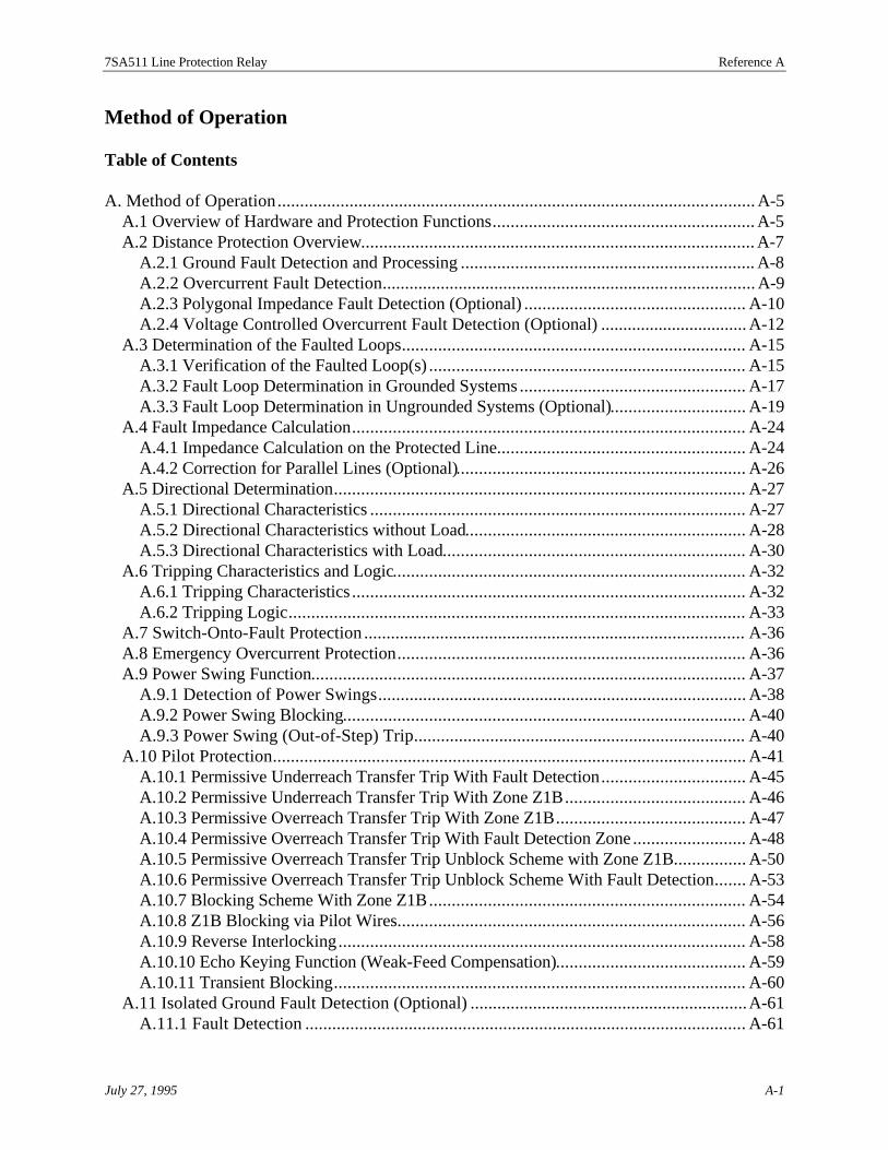
7SA511 Line Protection Relay Reference A
July 27, 1995 A-1
Method of Operation
Table of Contents
A. Method of Operation.......................................................................................................... A-5A.1 Overview of Hardware and Protection Functions.......................................................... A-5A.2 Distance Protection Overview....................................................................................... A-7
A.2.1 Ground Fault Detection and Processing................................................................. A-8A.2.2 Overcurrent Fault Detection................................................................................... A-9A.2.3 Polygonal Impedance Fault Detection (Optional).................................................A-10A.2.4 Voltage Controlled Overcurrent Fault Detection (Optional) .................................A-12
A.3 Determination of the Faulted Loops............................................................................A-15A.3.1 Verification of the Faulted Loop(s)......................................................................A-15A.3.2 Fault Loop Determination in Grounded Systems..................................................A-17A.3.3 Fault Loop Determination in Ungrounded Systems (Optional)..............................A-19
A.4 Fault Impedance Calculation.......................................................................................A-24A.4.1 Impedance Calculation on the Protected Line.......................................................A-24A.4.2 Correction for Parallel Lines (Optional)................................................................A-26
A.5 Directional Determination...........................................................................................A-27A.5.1 Directional Characteristics...................................................................................A-27A.5.2 Directional Characteristics without Load..............................................................A-28A.5.3 Directional Characteristics with Load...................................................................A-30
A.6 Tripping Characteristics and Logic..............................................................................A-32A.6.1 Tripping Characteristics.......................................................................................A-32A.6.2 Tripping Logic.....................................................................................................A-33
A.7 Switch-Onto-Fault Protection .....................................................................................A-36A.8 Emergency Overcurrent Protection.............................................................................A-36A.9 Power Swing Function................................................................................................A-37
A.9.1 Detection of Power Swings..................................................................................A-38A.9.2 Power Swing Blocking.........................................................................................A-40A.9.3 Power Swing (Out-of-Step) Trip..........................................................................A-40
A.10 Pilot Protection.........................................................................................................A-41A.10.1 Permissive Underreach Transfer Trip With Fault Detection................................A-45A.10.2 Permissive Underreach Transfer Trip With Zone Z1B........................................A-46A.10.3 Permissive Overreach Transfer Trip With Zone Z1B..........................................A-47A.10.4 Permissive Overreach Transfer Trip With Fault Detection Zone.........................A-48A.10.5 Permissive Overreach Transfer Trip Unblock Scheme with Zone Z1B................A-50A.10.6 Permissive Overreach Transfer Trip Unblock Scheme With Fault Detection.......A-53A.10.7 Blocking Scheme With Zone Z1B......................................................................A-54A.10.8 Z1B Blocking via Pilot Wires.............................................................................A-56A.10.9 Reverse Interlocking..........................................................................................A-58A.10.10 Echo Keying Function (Weak-Feed Compensation)..........................................A-59A.10.11 Transient Blocking...........................................................................................A-60
A.11 Isolated Ground Fault Detection (Optional) ..............................................................A-61A.11.1 Fault Detection ..................................................................................................A-61

7SA511 Line Protection Relay Method of Operation
A-2 July 27, 1995
A.11.2 Determination of the Faulted Phase....................................................................A-61A.11.3 Directional Determination..................................................................................A-61A.11.4 Ground Fault Location.......................................................................................A-63
A.12 High-Resistance Ground Fault Protection for Grounded Systems (Optional).............A-65A.12.1 Directional Ground Fault Overcurrent Protection with Nondirectional Backup... A-66A.12.2 Directional Comparison Ground Fault Protection...............................................A-67A.12.3 Non-Directional Inverse Time Ground Fault Protection......................................A-68
A.13 Automatic Reclose (Optional)...................................................................................A-69A.13.1 Selectivity During Automatic Reclose................................................................A-71A.13.2 Treatment of Evolving Faults.............................................................................A-73A.13.3 Treatment of Multiple Single-Phase Faults.........................................................A-73A.13.4 Multi-Shot Automatic Reclose...........................................................................A-74A.13.5 Manual Close Onto Fault...................................................................................A-74A.13.6 External Automatic Reclose System...................................................................A-75A.13.7 External Control of the Internal Automatic Reclose............................................A-76A.13.8 Interconnecting Two Automatic Reclose Relays.................................................A-77
A.14 Fault Locating..........................................................................................................A-78A.15 Ancillary Functions...................................................................................................A-79
A.15.1 LEDs and Binary Outputs (Signal Relays)..........................................................A-79A.15.2 Digital Communications.....................................................................................A-79A.15.3 Target Logs .......................................................................................................A-80A.15.4 Waveform Capture.............................................................................................A-80A.15.5 Measured Values and Load Data........................................................................A-80A.15.6 Self-Diagnostics.................................................................................................A-80
List of Figures
Figure A-1 Hardware Structure of the 7SA511 Relay............................................................. A-6Figure A-2. Ground Current Detector Characteristic .............................................................. A-9Figure A-3. Impedance Fault Detection Characteristic..........................................................A-11Figure A-4. Voltage Controlled Overcurrent Fault Detection Characteristic..........................A-13Figure A-5. Phase-to-Phase Short Circuit Loop....................................................................A-16Figure A-6. Phase-to-Ground Short Circuit Loop.................................................................A-17Figure A-7. Ground Fault in an Ungrounded System............................................................A-20Figure A-8. Phase-to-Phase Fault Resistance........................................................................A-25Figure A-9. Phase-to-Ground Fault Resistance.....................................................................A-26Figure A-10. Ground Fault on a Parallel Line.......................................................................A-27Figure A-11. Reference Voltages for Directional Determination...........................................A-28Figure A-12. Relay 7SA511, Directional Characteristics.......................................................A-29Figure A-13. Directional Characteristic with Source Impedance and No Load Transport......A-30Figure A-14. Voltage Phasors and Directional Characteristics for a Loaded Line..................A-31Figure A-15. Tripping Characteristics...................................................................................A-34Figure A-16. Logic Diagram of Distance Protection Tripping...............................................A-35Figure A-17. Logic Diagram of the Switch-Onto-Fault Protection........................................A-36

7SA511 Line Protection Relay Reference A
July 27, 1995 A-3
Figure A-18. Power Swing...................................................................................................A-38Figure A-19. Pickup Characteristic for the Detection of Power Swings.................................A-39Figure A-20. Permissive Underreach Transfer Trip With Fault Detection..............................A-45Figure A-21. Permissive Underreach Transfer Trip With Zone Z1B......................................A-46Figure A-22. Permissive Overreach Transfer Trip With Zone Z1B........................................A-47Figure A-23. Permissive Overreach Transfer Trip With Fault Detection Zone.......................A-48Figure A-24. POTT Unblock Scheme With Zone Z1B..........................................................A-50Figure A-25. Unblocking Logic............................................................................................A-51Figure A-26. Generating the Communications Failure (Fault) Signal F..................................A-51Figure A-27. POTT Unblock With Fault Detection Zone......................................................A-53Figure A-28. Z1B Blocking..................................................................................................A-54Figure A-29. Z1B Blocking via Pilot Wires..........................................................................A-56Figure A-30. Reverse Interlocking Scheme With Distance Zones..........................................A-58Figure A-31. Echo Keying Function.....................................................................................A-59Figure A-32. Transient Blocking With Release Scheme........................................................A-60Figure A-33. Directional Ground Fault Measurement Characteristic for cos f.......................A-62Figure A-34. Faulted Line Location in a Radial System........................................................A-64Figure A-35. Faulted Line Location in a Meshed System......................................................A-64Figure A-36. Directional Ground Fault Protection With Nondirectional Backup...................A-66Figure A-37. Directional Comparison Ground Fault Protection............................................A-67Figure A-38. Automatic Reclose Sequence...........................................................................A-70Figure A-39. Zone Reach Control With the Automatic Reclose Function..............................A-72Figure A-40. Multiple Faults on a Parallel Line.....................................................................A-74Figure A-41. Example of Connections to an External Automatic Reclose System.................A-75Figure A-42. Example of External Control of Internal Automatic Reclose............................A-76Figure A-43. Example of Connections for Dual Automatic Reclose......................................A-77

7SA511 Line Protection Relay Method of Operation
A-4 July 27, 1995
This page intentionally blank

7SA511 Line Protection Relay Reference A
ed torheadckup
the
511
in
nts forto theodule.tion
3
threeond
he threetion
hewing:
A. Method of Operation
A.1 Overview of Hardware and Protection Functions
The 7SA511 relay is a microprocessor-based, high speed, numerical distance relay designprovide fast, reliable, and selective clearance of all kinds of ground and phase faults on ovelines and cables being fed from one point or multiple points. It can also be used as local baand/or bus protection through reverse interlocking or to provide backup protection forgenerators, and it can be installed on grounded or ungrounded systems. Figure A-1 showsbasic structure of the unit.
The relay provides full digital processing of all functions, from data acquisition of measuredvalues to the trip commands for the circuit breaker. Protection functions provide by the 7SArelay are:
· Distance protection (21/21G) with directional discrimination· Power swing protection (78)· Emergency overcurrent protection (50/51/50G/51G)· Pilot protection (85)· High-resistance ground fault protection (50G/51G) with directional discrimination
grounded systems· Automatic reclose (79)· Ground fault detection with directional discrimination in ungrounded (isolated or
compensated) systems
The analog input module (see Figure A-1) contains input amplifiers, sample and hold elemeeach input, multiplexers, and analog/digital converters. Analog current input signals enter inrelay isolating transformers and then pass through anti-aliasing filters to the analog input mThe anti-aliasing filters’ bandwidth and processing speed are optimized to match the protecalgorithms. The input signals are sampled 20 times per power cycle (one sample every 0.8milliseconds at 60 Hz) and converted to digital signals.
The 7SA511 relay has seven voltage transformers and four current transformers. The first voltage transformers are wired in a wye to measure the phase-to-ground voltages. The secthree voltage transformers are wired in a delta to measure the phase-to-phase voltages. Tdelta terminals are internally connected in parallel with the three wye terminals. This connecscheme results in a total of 4 inputs - one for each of the three phases and the neutral. Theremaining voltage transformer input VE is used for measurement of the displacement voltage VE
from the broken-delta windings of the VTs. Three of the five current inputs are for input of tphase currents of the protected line. The remaining current input is used for one of the follo
· Residual current of the protected line· Ground current of a parallel line for parallel line compensation· Neutral current of a grounded infeed transformer for directional ground fault
protection
July 27, 1995 A-5

7SA511 Line Protection Relay Method of Operation
lays.
The relay also has 10 optically isolated binary inputs, 16 LEDs, 5 trip relays, and 11 signal reMicroprocessor
Blocked
Ready
11 Signal Relays(programmable)
A/D Converter
MUX
MUXIsolating
Transformers
Power SystemBus
Line
L1L2L3
LCD
Rear PortSerial Interfacewith isolation
Front PortSerial Interface
5 Trip Relays(programmable)
SubstationControl System
PersonalComputer
10 BinaryInputs
(Programmable)
Power SupplyDC
DC
MembraneKeypad
14 LEDs(programmable)
IL1
VL1
VL2
VL3
VE
IL2
IL3
IE
PowerFlow
Forward
Reverse
P-G
P-G
P-P
P-P
P-P
P-G
Figure A-1 Hardware Structure of the 7SA511 Relay
A-6 July 27, 1995

7SA511 Line Protection Relay Reference A
tection
tacts,,
andrget usingator
lows:
canthe
-
d.
The microprocessor performs all impedance and overcurrent calculations and makes all prologic decisions. The microprocessor also provides the following functions:
· Filtering and formation of the measured quantities· Continuous calculation of the values required for fault detection· Determination of the faulted phases and the direction of faults· Scanning of limit values and time sequences· Controlling of signals and sequences for pilot protection, automatic reclose, etc.· Decision for tripping circuit breakers· Storage of instantaneous current and voltage values during a fault· Storage and issue of messages and fault data for fault analysis
Binary inputs are isolated through optical couplers. Outputs include trip contacts, signal conLEDs, and an alphanumeric LCD on the operator panel. You can program the binary inputsoutput contacts, and LEDs as discussed in Chapter 5, “Programming the Relay.”
Using the operator panel keypad and LCD, you can read or change the system, protection,relay configuration settings, access and read the relay’s measured values, and review the tahistory logs for the last three faults. This interaction with the relay can also be accomplishedDIGSIÒ software on a personal computer connected to the serial interface port on the operpanel (refer to Figure 2-1 in Chapter 2, “Product Description”).
An integrated DC-to-DC converter supplies multiple voltages to the relay subsystems as fol
Voltage Subsystem+24 V Output relays±15 V A/D converters+12 V EEPROMs+ 5 V CPU and associated logic
The relay can withstand a loss of input supply voltage for 50 milliseconds (VH ³ 110 V) withoutgoing out of service (refer to Reference D, “Specifications”).
A.2 Distance Protection Overview
Distance protection is the main function of the 7SA511 relay. Depending on the model, you choose from three different fault detector combinations to ensure the optimal protection for protected system. The fault detector combinations can be any one of the following:
· Overcurrent (7SA511*-**A51-****)· Overcurrent, Voltage-controlled overcurrent, and Polygonal impedance (7SA511*
**A5 2-****)· Overcurrent and Voltage-controlled overcurrent (7SA511*-**A53-****)
In addition to the above fault detectors, an independent distance-to-fault function is provide
July 27, 1995 A-7

7SA511 Line Protection Relay Method of Operation
en
nt
helt.
ase
ts (
withs.
When a fault is detected the following procedures are initiated:
· Trip delays· Determination of the faulted line loop(s)· Release of trip commands· Auxiliary functions· Identification of the faulty phase(s)
The overcurrent fault detection unit is used for high fault current detection. If there is nosignificant difference between normal current (including overload) and short circuit current, ththe voltage controlled overcurrent or polygonal impedance fault detection unit must be used.Power systems with highly fluctuating system impedance or systems using short circuit currelimiting devices also require voltage controlled overcurrent or polygonal impedance faultdetection units.
A.2.1 Ground Fault Detection and ProcessingAn important element for all fault detection methods is the detection of a ground fault since tdetermination of the fault type or faulty line loop depends on whether or not it is a ground fauThe 7SA511 relay is equipped with restraint measurement of the ground current as well asdetection of the displacement voltage. Fault detection is suppressed in the case of single-phground faults in ungrounded or reactance-grounded systems.
The ground current detector monitors the fundamental wave of the total of the phase currenIE
= 3I0) in comparison with the threshold value. It is restrained against faulty pickup caused byasymmetric operating currents or distorted currents in the secondary circuit of the currenttransformers (CTs) resulting from different CT saturation with ground-free short circuits. Theactual pickup value is automatically increased as the phase currents increase. In Figure A-2,an example for setting IE>/IN = 0.2, the horizontal branch is shifted according to different settingThe reset value is 95% of the pickup value.
A-8 July 27, 1995

7SA511 Line Protection Relay Reference A
e
r
l of
isms, akupinction
the
e.
n
d intocord-e-
00
0.2
0.4
0.6
0.8
1.0
1 2 3 4
IE pick-up
IE reset
5 6 7Iph max
IN
IE>IN
Pickup
10%
Figure A-2. Ground Current Detector Characteristic
The displacement voltage detector monitors the fundamental wave of the displacement voltag(VE = 3V0) in comparison with the set threshold value. The reset value is 95% of the pickupvalue.
In grounded systems (solidly or resistance grounded), the pickup of the ground current monitoor the displacement voltage monitor lead to pickup of the ground fault detector. Detection of aground fault on its own is not announced, and it does not lead to a general fault detection signathe distance protection. It does, however, control the other fault detection elements.
In ungrounded systems (isolated or compensated starpoint), the displacement voltage monitornot used for ground fault detection. When a single-phase fault detection occurs in these systesingle-phase ground fault is initially assumed and detection is suppressed to prevent faulty picby the oscillation transients on the occurrence of a simple ground fault. Pickup is enabled agafollowing an adjustable delay time (address 1801); this is necessary so that the distance proteis still able to recognize a double ground fault with one base point on a spur feeder. A groundfault that is already present in the system is detected by the displacement voltage monitor, sodelay is not effective—a fault which now occurs in another phase can only be a double-phaseground fault.
A.2.2 Overcurrent Fault DetectionOvercurrent fault detection in the 7SA511 relay is a phase-dedicated fault detection procedurFollowing digital filtering, the currents in each phase are monitored in comparison with a setthreshold value. A pickup signal is output for the phase(s) for which the set threshold has beeexceeded.
To enable measured value selection, the phase-dedicated fault detection signals are convertephase-loop information (see section A.3). In grounded systems, this process is carried out acing to the ground fault detection function and the parameter, 1PH FAULTS, selected for singl
July 27, 1995 A-9

7SA511 Line Protection Relay Method of Operation
the
ealue
t
-3)
ted
on the
phase pickup without ground fault detection. In ungrounded system, the multi-phase loop isalways selected in the case of a single-phase pickup without ground fault detection.
The faulty phases are indicated (see Table A-1). The overcurrent fault detector is reset whenpickup value is below 95%.
Table A-1. Single-Phase Overcurrent Fault DetectionFault Detection
ModuleGround Fault
DetectionParameter (1705)
1PH FAULTSResultant Loop Annunciation
L1L2L3
nonono
PHASE-PHASE(Uph - Uph)
L3-L1L1-L2L2-L3
L1L2L3
L1L2L3
nonono
PHASE-EARTH *(Uph - E)
L1-EL2-EL3-E
L1L2L3
L1L2L3
yesyesyes
irrelevant L1-EL2-EL3-E
L1, EL2, EL3, E
* Only applicable for grounded systems.
A.2.3 Polygonal Impedance Fault Detection (Optional)Polygonal impedance fault detection is a loop-dedicated fault detection procedure. Either thethree phase-to-phase loops (without ground fault) or the three phase-to-ground loops (withground fault) are monitored depending on the result of the ground fault detection. Formeasurement of a loop impedance, at least one of the assigned phase currents as well as thdifference current decisive for the loop must have exceeded the minimum operating current vIph>.
The impedances are calculated separately for resistance, R, and reactance, X, in cyclic timeintervals and compared with the set values of any of the six line loops for which the currentconditions are met. A measured value step change monitor is used to synchronize themeasurement window on occurrence of a fault. The calculation procedure is the same as thadescribed for distance measurement.
The polygonal impedance fault detector utilizes a special “dog bone” characteristic (Figure Ato provide secure pickup for faults without pickup on load. The X-intersections X+A and X-A aredecisive for the fault reach in the forward and reverse directions respectively. The R-intersectionscan be set differently for multi-phase loops (RA1) and phase-to-ground loops (RA1E). It is thereforepossible, for example, to permit a larger fault resistance tolerance for ground faults (bold dotlines in Figure A-3). Extension of the polygon in the R-direction is only valid when a ground faulthas been detected as described in the previous section.
In order to guarantee the criteria for distinction between load operation and a short-circuit,especially in the case of long, heavily loaded lines, the characteristics can be set dependent
A-10 July 27, 1995

7SA511 Line Protection Relay Reference A
phase angle with the RA2 intersection applicable for phase angles above 45°, and the RA1
intersection applicable for phase angles below 45°.
Forwarddirection
Reversedirection
X
X+A
X-A
RA1
RA2
RAE
R
45°
Figure A-3. Impedance Fault Detection Characteristic
July 27, 1995 A-11

7SA511 Line Protection Relay Method of Operation
6% is
e
he
ntteda highrentnset.
ctedems
seet
easures
faultteristic
ed by
ify the
ectiveea.
To avoid intermittent pickup signals near the perimeter of the characteristic, a hysteresis of provided.
Pickup results for the measurement loop in which the impedance vector lies within the faultdetection polygon (shaded area in Figure A-3). If detection occurs in more than one loop, threlay regards as valid all loops whose impedance is not greater than 150% of that smallestimpedance. This avoids incorrect pickup signals which could be caused by the influence of tfault currents and voltages on the unfaulted line loops, especially in cases of small sourceimpedances.
The impedance fault detection for phase-to-ground loops is supplemented by the overcurreelement (I>>) where pickup of only the overcurrent element leads to detection if the associaimpedance loop has been eliminated as described above. In this manner, double faults with current are also detected even though the fault loop has been eliminated. Since the overcurelement can only re-establish eliminated loops for pickup, erroneous fault detection due to aovercurrent is prevented if the short-circuit currents in the fault-free phases can exceed the overcurrent value on ungrounded feeding transformers or grounded consumer transformers
Impedance fault detection can be used only for ground faults where the phase-to-groundmeasurement is enabled by ground fault detection. Phase-phase faults in this case are detewith high-set overcurrent (I>>) element. This detection program is only of advantage in systwith limiters for ground currents (grounded with low impedance—resistance grounding) where ashort-circuit current, sufficient for pickup by the overcurrent element, flows for phase-to-phafaults but not for phase-to-ground faults. Ground-free faults are thus detected by the high-sovercurrent element (I>>).
Pickup caused by single-phase ground faults in ungrounded systems is suppressed by the mdescribed in section A.2.1.
A.2.4 Voltage Controlled Overcurrent Fault Detection (Optional)Voltage controlled overcurrent (a.k.a. underimpedance) fault detection is a phase-dedicateddetection procedure which also takes loop information into consideration. The basic characis shown in Figure A-4. Phase pickup occurs when the minimum operating current Iph>, isexceeded. Above this current, voltage controlled overcurrent detection, whose slope is definthe parameters V(Iph>) and V(Iph>>), is effective. A high-set overcurrent element I>> issuperimposed in the case of short-circuits of high current. The bold dots in Figure A-4 identsetting parameters which determine the geometry of the current/voltage characteristic.
Fault detection of a phase is reset when the respective current is less than 95%, or the respvoltage is greater than 105%. The shaded area in Figure A-4 identifies the fault detection ar
A-12 July 27, 1995

7SA511 Line Protection Relay Reference A
-
ynded),
ticallyadowskup if
2 310
0
10
20
30
40
50
60
70
Iph>>Iph>
V(Iph>)
V(Iph>>)
I/IN
V
Pickup
Figure A-4. Voltage Controlled Overcurrent Fault Detection Characteristic
Each of the three fault detection modules is controlled by the phase-to-ground voltages (VPh-E) orthe phase-to-phase voltages (VPh-Ph). You must program the relay to indicate whether the phaseto-ground voltages (VPh-E) or the phase-to-phase voltages (VPh-Ph) are decisive, or whether thisdepends on the ground fault detection as described in section A.2.1. Optimum control largeldepends on whether the system neutral is grounded with a low impedance (resistance grouis solidly grounded, or is not grounded (isolated or compensated).
Control with phase-to-ground voltage (VPh-E) is characterized by a high sensitivity to groundshort-circuits and is, therefore, particularly advantageous in grounded systems. It is automaadapted to the existing load conditions (i.e., it becomes more current sensitive during low-looperation), and the pickup threshold is higher in the case of high load currents. Table A-2 shthe assignment of the phase currents, loop voltages and output results with single-phase piccontrol with phase-to-ground voltages is selected.
Table A-2. Voltage Controlled Overcurrent Fault Detection - With Phase-to-Ground VoltagesFault Detection
ModuleMeasuredCurrent
MeasuredVoltage
GroundFault
Detection
Parameter (1705)1PH FAULTS
ResultantLoop
Annunciation
L1L2L3
L1L2L3
L1-EL2-EL3-E
nonono
PHASE-PHASE(Uph - Uph)
L3-L1L1-L2L2-L3
L1L2L3
L1L2L3
L1L2L3
L1-EL2-EL3-E
nonono
PHASE-EARTH*(Uph - E)
L1-EL2-EL3-E
L1L2L3
L1L2L3
L1L2L3
L1-EL2-EL3-E
yesyesyes
irrelevant L1-EL2-EL3-E
L1, EL2, EL3, E
* Only applicable for grounded systems
July 27, 1995 A-13

7SA511 Line Protection Relay Method of Operation
nle A--phase
leitionsingble A-phase
ty foriple,ult
single-
current
t faultows
In grounded systems, the measured line loop depends on the ground fault detection functio(section A.2.1) and the parameter, 1PH FAULTS (address 1705), selected according to Tab2. In ungrounded system, the phase-to-phase loop is always selected in the case of a singlepickup without ground fault detection. The faulty phases are identified.
Sensitivity is particularly high in phase-to-phase faults when controlling with phase-to-phasevoltages (VPh-Ph). This control is advantageous with compensated systems because its principexcludes pickup by single ground faults. It is adapted automatically to the existing load condin the case of two-phase and three-phase faults (i.e., it becomes more current sensitive durlow-load operation), and the pickup threshold is higher in the case of high load currents. Ta3 shows the assignment of the phase currents, loop voltages and output results with single-pickup if control with phase-to-phase voltages is selected.
Table A-3. Voltage Controlled Overcurrent Fault Detection - With Phase-to Phase VoltagesFault
DetectionModule
MeasuredCurrent
MeasuredVoltage
Ground FaultDetection
Parameter(1705)
1PH FAULTS
ResultantLoop
Annunciation
L1L2L3
L1L2L3
L1-L2L2-L3L3-L1
irrelevant irrelevant L1-L2L2-L3L3-L1
L1L2L3
If the voltage loops are set to be dependent on the ground fault detection, the high sensitiviphase-to-ground faults then also applies to phase-to-phase faults. This possibility is, in princindependent of the treatment of the system neutral; it assumes, however, that the ground facriteria according to section A.2.1 have been satisfied safely for all ground faults. Table A-4applies to the fault detection program for phase-to-ground or phase-to-phase voltages with phase pickup.
Table A-4. Voltage Controlled Overcurrent Fault Detection - Phase-to Ground Voltages WithGround Fault and Phase-to-Phase Voltages Without Ground Fault
FaultDetectionModule
MeasuredCurrent
MeasuredVoltage
Ground FaultDetection
Parameter(1705)
1PH FAULTS
ResultantLoop
Annunciation
L1L2L3
L1L2L3
L1-L2L2-L3L3-L1
nonono
irrelevant L1-L2L2-L3L3-L1
L1L2L3
L1L2L3
L1L2L3
L1-EL2-EL3-E
yesyesyes
irrelevant L1-EL2-EL3-E
L1, EL2, EL3, E
It is also possible to control with phase-to-ground voltage loops (VPh-E) when a ground fault hasbeen detected. Detection for phase-to-phase faults then takes place only with high-set over(I>>). This option is advantageous in systems with a low-impedance ground (resistancegrounding) when only ground faults are to be detected by the voltage controlled overcurrendetection. The measured loop is independent of the parameter 1PH FAULTS. Table A-5 sh
A-14 July 27, 1995

7SA511 Line Protection Relay Reference A
p
he
s
rt
the assignment of the phase currents, loop voltages and output results for single-phase pickuwith ground fault detection only.
Table A-5. Single-Phase, Voltage Controlled Overcurrent Fault Detection - Phase-to-GroundVoltage With Ground Fault Detection OnlyFault Detection
ModuleMeasuredCurrent
MeasuredVoltage
Ground FaultDetection
Parameter (1705)1PH FAULTS
ResultantLoop
Annunciation
L1L2L3
L1L2L3
L1-EL2-EL3-E
yesyesyes
irrelevant L1-EL2-EL3-E
L1, EL2, EL3, E
L1L2L3
L1L2L3
L1-EL2-EL3-E
nonono
irrelevant no pickup and annunciationby VPH-E</I>
A.3 Determination of the Faulted Loops
A.3.1 Verification of the Faulted Loop(s)The currents and voltages of the faulty loop are used for calculation of the fault impedance. Tphase selective fault detector determines the faulted loop and determines the correspondingmeasurement values for impedance calculation. The selection of valid short circuit loops varieconsiderably, depending upon whether the system is grounded, isolated, or compensated.
For example, when calculating the impedance of a phase-to-phase loop for a two phase shocircuit in L1-L2 (Figure A-5), the following identity applies:
I Z I Z V VL L L L L L1 2 1 1− = −
where V and I are complex measured values (phasors),and Z = R + jX is the complex line impedance.
The line impedance is
ZV VI IL
L L
L L
= −−
1 2
1 2
.
July 27, 1995 A-15

7SA511 Line Protection Relay Method of Operation
thatase. In
o the
L1
L2
L3
E
ZL
ZL
VL1
VL2
IL1
IL2
Figure A-5. Phase-to-Phase Short Circuit Loop
For calculation of a phase-to-ground loop for a short circuit in L3-E (Figure A-6), observethe impedance of the ground return path is not normally equal to the impedance of the phthe loop equation
I Z I Z VL L E E L E3 3− = − ,
ZE is replaced by ZZ
ZE
LL , which gives us
I Z I ZZZ
VL L E LE
LL E3 3− = − ,
from which you obtain the line impedance
ZV
IZZ
IL
L E
LE
LE
=−
−3
3
,
whereby the factor ZZ
E
L
is dependent only upon the line constants and not on the distance t
fault.
A-16 July 27, 1995

7SA511 Line Protection Relay Reference A
cuit in
) orlay sohe
ctedione
on,. If-
in
L1
L2
L3
E
ZL
ZE
VL3-E
IL3
IE
Figure A-6. Phase-to-Ground Short Circuit Loop
A.3.2 Fault Loop Determination in Grounded SystemsIn power systems with grounded neutrals, each contact of a phase with ground is a short cirthat must be interrupted immediately by the nearest protective device. Fault detection occursthe faulted loop.
With double faults, pickup normally occurs in two phases and ground (overcurrent detectionfor two phase-to-ground loops (impedance detection). In this case, it is possible to set the rethat preference is given to one of the fault loops. Only the phase-to-phase loop, the loop of tleading phase-to-ground, or the loop of the lagging phase-to-ground will be selected.
Note: In grounded power systems, the relay must be connected to three wye-conneVTs with grounded primary common and to three CTs. The common connectfor the CTs should be connected to the ground current input of the relay. If thcurrent input of the relay is fed from other current sources, such as from thecommon connection of the CT set of a parallel line for parallel line compensatithe relay calculates the ground fault from the sum of the three phase currentsthe VTs have residual voltage windings, these should be connected in brokendelta to the voltage input to enable the relay to monitor the VTs’ secondarycircuits.
Table A-6 and Table A-7 show the measurement quantities used for distance measurement grounded systems.
July 27, 1995 A-17

7SA511 Line Protection Relay Method of Operation
Table A-6. Selected Measurement Quantities in Grounded Systems, withOvercurrent Fault Detection (With or Without Voltage Control)
Fault Detection Phases Selected Loop Selected Setting ParameterL1, EL2, EL3, E
L1-EL2-EL3-E
irrelevant
L1, L2L2, L3L1, L3
L1-L2L2-L3L3-L1
irrelevant
L1, L2, EL2, L3, EL1, L3, E
L1-L2L2-L3L3-L1
2PH-E FLTS =PHASE-PHASE
L1, L2, EL2, L3, EL1, L3, E
L1-EL2-EL3-E
2PH-E FLTS =LEADING PH-E
L1, L2, EL2, L3, EL1, L3, E
L2-EL3-EL1-E
2PH-E FLTS =LAGGING PH-E
L1, L2, L3L1, L2, L3, E
L3-L1L3-E
3PH FAULTS =E/F CONTROL
L1, L2, L3L1, L2, L3, E
L3-L1L3-L1
3PH FAULTS =PH-PH ONLY
L1, L2, L3L1, L2, L3, E
L3-EL3-E
3PH FAULTS =PH-E ONLY
A-18 July 27, 1995

7SA511 Line Protection Relay Reference A
n the
etworkltage ofoint, a of one
Table A-7. Selected Measurement Quantities in Grounded Systems, withImpedance Fault Detection
Fault DetectionPhase Loops
Selected Loop Selected Setting Parameter
L1-EL2-EL3-E
L1-EL2-EL3-E
irrelevant
L1-L2L2-L3L3-L1
L1-L2L2-L3L3-L1
irrelevant
L1-E, L2-EL2-E, L3-EL1-E, L3-E
L1-L2L2-L3L3-L1
2PH-E FLTS =PHASE-PHASE
L1-E, L2-EL2-E, L3-EL1-E, L3-E
L1-EL2-EL3-E
2PH-E FLTS =LEADING PH-E
L1-E, L2-EL2-E, L3-EL1-E, L3-E
L2-EL3-EL1-E
2PH-E FLTS =LAGGING PH-E
L1-L2, L2-L3L2-L3, L3-L1L3-L1, L1-L2
L1-L2L2-L3L3-L1
irrelevant
L1-E, L2-E, L3-EL1-L2, L2-L3, L3-L1
L3-EL3-L1
3PH FAULTS =E/F CONTROL
L1-E, L2-E, L3-EL1-L2, L2-L3, L3-L1
L3-L1L3-L1
3PH FAULTS =PH-PH ONLY
L1-E, L2-E, L3-EL1-L2, L2-L3, L3-L1
L3-EL3-E
3PH FAULTS =PH-E ONLY
A.3.3 Fault Loop Determination in Ungrounded Systems (Optional)In isolated or compensated networks, currents resembling a short circuit are not present icase of a single-phase ground fault. Only a displacement of the voltage triangle occurs, asillustrated in Figure A-7, and this condition does not represent any immediate danger to noperation. In this case, the distance protection must not trip since the phase-to-ground vothe faulty phase is zero throughout the network. A trip would lead to, at each measuring pmeasured impedance equal to zero for the faulty phase-to-ground loop. Therefore, pickupsingle phase-to-ground fault detector is avoided in the 7SA511 relay.
July 27, 1995 A-19


![Transmission Line Differential Protection Based on ...discussed line differential protection based on IEC 61850. In [9] an adaptive current line differential protection scheme is proposed](https://img.dokumen.tips/doc/110x75/5e7b1116957fb414ac4ec632/transmission-line-differential-protection-based-on-discussed-line-differential.jpg)