Embed Size (px)
Citation preview
1
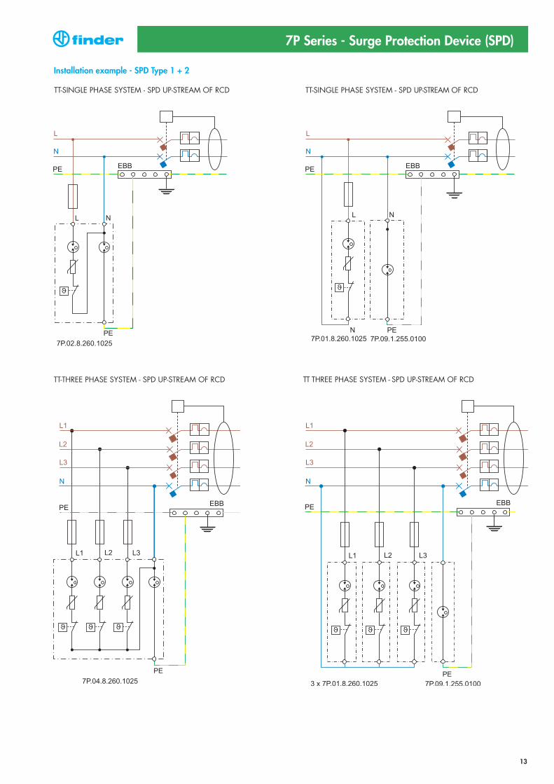
7P.09.1.255.0100 7P.01.8.260.1025 7P.02.8.260.1025
• SPD Type 1+2• Combination of varistor and encapsulated spark gap
• Visual fault signalling varistorstatus
• SPD Type 1• Spark gap module for N-PE application
• SPD Type 1+2• Combination of varistor and encapsulated spark gap + spark gap
• Visual fault signalling for each varistor module
SPD specification
Nominal voltage (UN) V AC
Maximum operating voltage (UC) V AC
Lightning impulse current (10/350 μs) (Iimp) kA
Nominal discharge current (8/20 μs) (In) kA
Maximum discharge current (8/20 μs) (Imax)kA
Voltage protection level (UP) kV
Ability to independently switch off the
following current (Ifi) A
Response time (ta) ns
Short-circuit proof at maximum overcurrent protection kArms
Maximum overcurrent protection
Other technical data
Ambient temperature range °C
Protection degree
Wire size
mm2
AWG
Wire strip length mm
Screw torque Nm
Remote status signalling contact specification
Contact configuration
Rated current A AC/DC
Rated voltage V AC/DC
Wire size (07P.01)
mm2
AWG
Approvals (according to type)
FeaturesSPD Type 1+2 Surge arrester range - single phasesystem / three phase system
• Surge arresters suitable in low-voltage applicationsin order to protect equipment against overvoltage by direct lightning strike, induction overvoltageand switching overvoltage.
• To be installed at the boundary of LPZ 0A - LPZ 1 zones or higher
• Versions with combination of varistor and encapsulated spark gap which eliminates leakagecurrent and ensures high discharge current
• Remote status signalling contact for each varistor module. Connector 07P.01 included
• Visual fault signalling• According to EN 61 643-11• 35 mm rail EN 60715 mounting, 35mm each pole
7P.09.1.255.0100 SPD Type 1, GDT protection for N-PE application only
7P.01.8.260.1025 SPD Type 1+2, varistor unipolar protection suitable to realize single phase or three phase systems (230/400 V) with the GDT protection (7P.09)
7P.02.8.260.1025 SPD Type 1+2 for single phase systrem. Varistor protection L-N + spark gap protection N-PE
7P Series - Surge Protection Device (SPD)
N-PE L-N N-PE
— 230 230 —
255 260 260 255
100 25 25 50
100 30 30 50
100 60 60 100
1.5 1.5 1.5 1.5
100 (@255 V AC)No following No following
100current current
100 100 100 100
— 35 35 —
— 160 A gL/gG 160 A gL/gG —
–40...+80
IP20
solid cable stranded cable
1x1...1x50 1x1...1x35
1x 17...1x1 1x 17...1x2
14
4
— 1 CO (SPDT) 1 CO (SPDT)
— 0.5 - 0.1 0.5 - 0.1
— 250 250
— solid cable stranded cable solid cable stranded cable
— 1.5 1.5 1.5 1.5
— 16 16 16 16
For outline drawing see page 10
7P.09 / 7P.01 / 7P.02Screw terminal
2
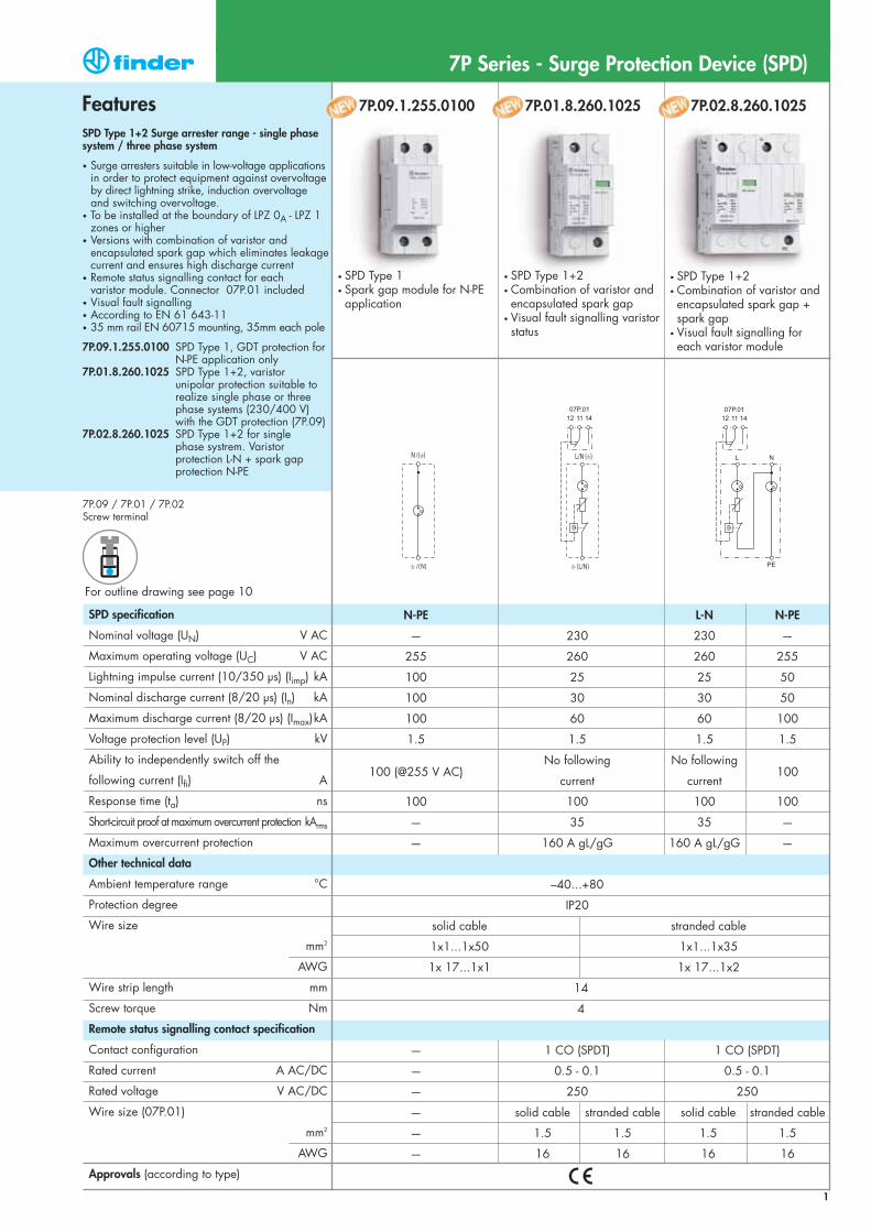
7P.03.8.260.1025 7P.04.8.260.1025 7P.05.8.260.1025
• SPD Type 1+2• 3 x combination of varistor and encapsulated spark gap + 1 encapsulated spark gap
• Visual fault signalling for each varistor module
• SPD Type 1+2• 3 x combination of varistor and encapsulated spark gap
• Visual fault signalling for each varistor module
• SPD Type 1+2• 4 x combination of varistor and encapsulated spark gap
• Visual fault signalling for each varistor module
SPD specification
Nominal voltage (UN) V AC
Maximum operating voltage (UC) V AC
Lightning impulse current (10/350 μs) (Iimp) kA
Nominal discharge current (8/20 μs) (In) kA
Maximum discharge current (8/20 μs) (Imax)kA
Voltage protection level (UP) kV
Ability to independently switch off the
following current (Ifi) A
Response time (ta) ns
Short-circuit proof at maximum overcurrent protection kArms
Maximum overcurrent protection
Other technical data
Ambient temperature range °C
Protection degree
Wire size
mm2
AWG
Wire strip length mm
Screw torque Nm
Remote status signalling contact specification
Contact configuration
Rated current A AC/DC
Rated voltage V AC/DC
Wire size (07P.01)
mm2
AWG
Approvals (according to type)
FeaturesSPD Type 1+2 Surge arrester range - three phasesystem (230/400 V)
• Surge arresters suitable in low-voltage applicationsin order to protect equipment against overvoltage by direct lightning strike, induction overvoltage andswitching overvoltage.
• To be installed at the boundary of LPZ 0A - LPZ 1 zones or higher
• Versions with combination of varistor and encapsulated spark gap which eliminates leakagecurrent and ensures high discharge current
• Remote status signalling contact for each varistor module. Connector 07P.01 included
• Visual fault signalling• According to EN 61 643-11• 35 mm rail EN 60715 mounting, 35mm each pole
7P.03.8.260.1025 SPD Type 1+2 for three phase system without Neutral (PEN conductor). Varistor protection L1, L2, L3-PEN
7P.04.8.260.1025 SPD Type 1+2 for three phase system with Neutral. Varistor protection L1, L2, L3-N + spark gap protection N-PE
7P.05.8.260.1025 SPD Type 1+2 for three phase system with Neutral (varistor N-PE). Varistor protection L1, L2, L3-N + varistor protection N-PE
7P Series - Surge Protection Device (SPD)
L-PEN L-N N-PE
230 230 — 230
260 260 255 260
25 25 100 25
30 30 100 30
60 60 100 60
1.5 1.5 1.5 1.5
No following No following100
No following
current current current
100 100 100 100
35 35 — —
160 A gL/gG 160 A gL/gG — 160 A gL/gG
–40...+80
IP20
solid cable stranded cable
1x1...1x50 1x1...1x35
1x 17...1x1 1x 17...1x2
14
4
1 CO (SPDT) 1 CO (SPDT) 1 CO (SPDT)
0.5 - 0.1 0.5 - 0.1 0.5 - 0.1
250 250 250
solid cable stranded cable solid cable stranded cable solid cable stranded cable
1.5 1.5 1.5 1.5 1.5 1.5
16 16 16 16 16 16
For outline drawing see page 10, 11
7P.03 / 7P.04 / 7P.05Screw terminal
3
SPD specification
Nominal voltage (UN) V AC
Maximum continous operating voltage (UC) V AC/DC
Lightning impulse current (10/350 μs) (Iimp) kA
Nominal discharge current (8/20 μs) (In) kA
Maximum discharge current (8/20 μs) (Imax)kA
Voltage protection level (UP) kV
Ability to independently switch off the
following current (Ifi) A
Response time (ta) ns
Short-circuit proof at maximum overcurrent protection kArms
Maximum overcurrent protection - fuse rating
Replacement modules code
Other technical data
Ambient temperature range °C
Protection degree
Wire size
mm2
AWG
Wire strip length mm
Screw torque Nm
Remote status signalling contact specification
Contact configuration
Rated current A AC/DC
Rated voltage V AC/DC
Wire size (07P.01)
mm2
AWG
Approvals (according to type)
For outline drawing see page 11
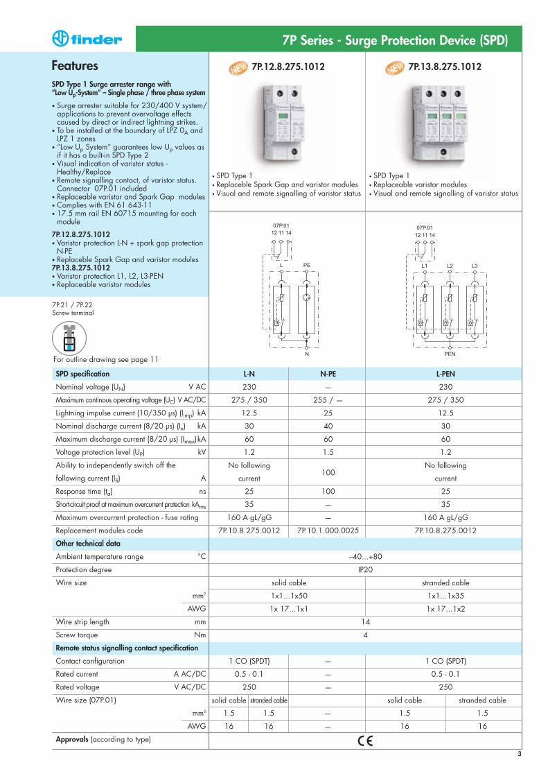
7P.12.8.275.1012 7P.13.8.275.1012
• SPD Type 1• Replaceable varistor modules • Visual and remote signalling of varistor status
• SPD Type 1• Replaceble Spark Gap and varistor modules• Visual and remote signalling of varistor status
FeaturesSPD Type 1 Surge arrester range with “Low Up-System” – Single phase / three phase system
• Surge arrester suitable for 230/400 V system/applications to prevent overvoltage effects caused by direct or indirect lightning strikes.
• To be installed at the boundary of LPZ 0A and LPZ 1 zones
• “Low Up System” guarantees low Up values as if it has a built-in SPD Type 2
• Visual indication of varistor status - Healthy/Replace
• Remote signalling contact, of varistor status. Connector 07P.01 included
• Replaceable varistor and Spark Gap modules• Complies with EN 61 643-11• 17.5 mm rail EN 60715 mounting for each
module
7P.12.8.275.1012• Varistor protection L-N + spark gap protection
N-PE• Replaceble Spark Gap and varistor modules7P.13.8.275.1012• Varistor protection L1, L2, L3-PEN• Replaceable varistor modules
7P Series - Surge Protection Device (SPD)
L-N N-PE L-PEN
230 — 230
275 / 350 255 / — 275 / 350
12.5 25 12.5
30 40 30
60 60 60
1.2 1.5 1.2
No following100
No following
current current
25 100 25
35 — 35
160 A gL/gG — 160 A gL/gG
7P.10.8.275.0012 7P.10.1.000.0025 7P.10.8.275.0012
–40...+80
IP20
solid cable stranded cable
1x1...1x50 1x1...1x35
1x 17...1x1 1x 17...1x2
14
4
1 CO (SPDT) — 1 CO (SPDT)
0.5 - 0.1 — 0.5 - 0.1
250 — 250
solid cable stranded cable solid cable stranded cable
1.5 1.5 — 1.5 1.5
16 16 — 16 16
7P.21 / 7P.22Screw terminal
4
SPD specification
Nominal voltage (UN) V AC
Maximum continous operating voltage (UC) V AC/DC
Lightning impulse current (10/350 μs) (Iimp) kA
Nominal discharge current (8/20 μs) (In) kA
Maximum discharge current (8/20 μs) (Imax)kA
Voltage protection level (UP) kV
Ability to independently switch off the
following current (Ifi) A
Response time (ta) ns
Short-circuit proof at maximum overcurrent protection kArms
Maximum overcurrent protection - fuse rating
Replacement modules code
Other technical data
Ambient temperature range °C
Protection degree
Wire size
mm2
AWG
Wire strip length mm
Screw torque Nm
Remote status signalling contact specification
Contact configuration
Rated current A AC/DC
Rated voltage V AC/DC
Wire size (07P.01)
mm2
AWG
Approvals (according to type)
For outline drawing see page 11
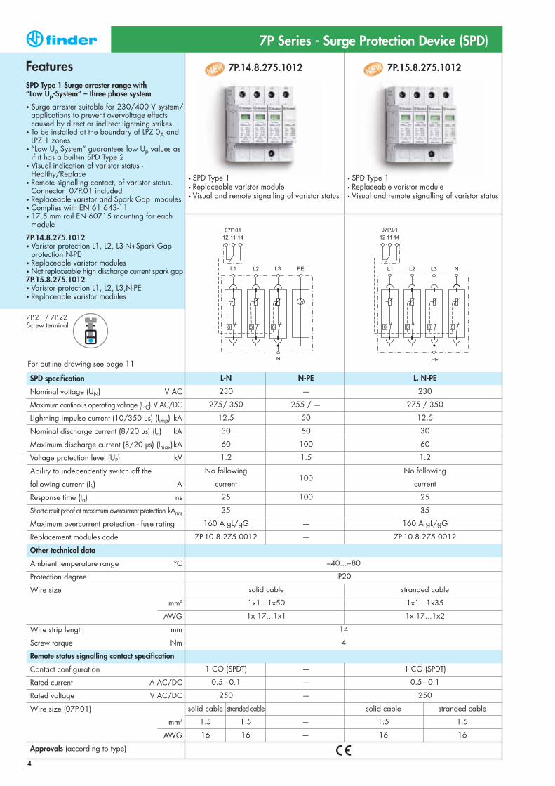
7P.14.8.275.1012 7P.15.8.275.1012
• SPD Type 1• Replaceable varistor module• Visual and remote signalling of varistor status
• SPD Type 1• Replaceable varistor module• Visual and remote signalling of varistor status
FeaturesSPD Type 1 Surge arrester range with “Low Up-System” – three phase system
• Surge arrester suitable for 230/400 V system/applications to prevent overvoltage effects caused by direct or indirect lightning strikes.
• To be installed at the boundary of LPZ 0A and LPZ 1 zones
• “Low Up System” guarantees low Up values as if it has a built-in SPD Type 2
• Visual indication of varistor status - Healthy/Replace
• Remote signalling contact, of varistor status. Connector 07P.01 included
• Replaceable varistor and Spark Gap modules• Complies with EN 61 643-11• 17.5 mm rail EN 60715 mounting for each
module
7P.14.8.275.1012• Varistor protection L1, L2, L3-N+Spark Gap
protection N-PE• Replaceable varistor modules• Not replaceable high discharge current spark gap7P.15.8.275.1012• Varistor protection L1, L2, L3,N-PE• Replaceable varistor modules
7P Series - Surge Protection Device (SPD)
L-N N-PE L, N-PE
230 — 230
275/ 350 255 / — 275 / 350
12.5 50 12.5
30 50 30
60 100 60
1.2 1.5 1.2
No following100
No following
current current
25 100 25
35 — 35
160 A gL/gG — 160 A gL/gG
7P.10.8.275.0012 — 7P.10.8.275.0012
–40...+80
IP20
solid cable stranded cable
1x1...1x50 1x1...1x35
1x 17...1x1 1x 17...1x2
14
4
1 CO (SPDT) — 1 CO (SPDT)
0.5 - 0.1 — 0.5 - 0.1
250 — 250
solid cable stranded cable solid cable stranded cable
1.5 1.5 — 1.5 1.5
16 16 — 16 16
7P.21 / 7P.22Screw terminal
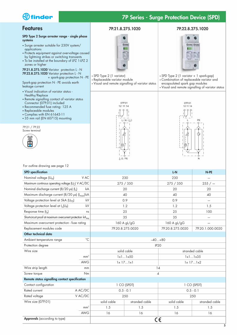
7P.21.8.275.1020 7P.22.8.275.1020
• SPD Type 2 (1 varistor + 1 spark-gap)• Combination of replaceable varistor and encapsulated spark gap modules
• Visual and remote signalling of varistor status
• SPD Type 2 (1 varistor)• Replaceable varistor module• Visual and remote signalling of varistor status
SPD specification
Nominal voltage (UN) V AC
Maximum continous operating voltage (UC) V AC/DC
Nominal discharge current (8/20 μs) (In) kA
Maximum discharge current (8/20 μs) (Imax)kA
Voltage protection level at 5kA (UP5) kV
Voltage protection level at In(UP) kV
Response time (ta) ns
Short-circuit proof at maximum overcurrent protection kArms
Maximum overcurrent protection - fuse rating
Replacement modules code
Other technical data
Ambient temperature range °C
Protection degree
Wire size
mm2
AWG
Wire strip length mm
Screw torque Nm
Remote status signalling contact specification
Contact configuration
Rated current A AC/DC
Rated voltage V AC/DC
Wire size (07P.01)
mm2
AWG
Approvals (according to type)
5
FeaturesSPD Type 2 Surge arrester range - single phase systems
• Surge arrester suitable for 230V system/applications
• Protects equipment against overvoltage causedby lightning strikes or switching transients
• To be installed at the boundary of LPZ 1-LPZ 2 zones or higher
7P.21.8.275.1020 Varistor protection L - N7P.22.8.275.1020 Varistor protection L - N
+ spark-gap protection N - PE
Spark-gap protection N - PE avoids earth leakage current
• Visual indication of varistor status - Healthy/Replace
• Remote signalling contact of varistor status Connector (07P.01) included
• Recommended fuse rating: 125 A• Replaceable modules• Complies with EN 61643-11• 35 mm rail (EN 60715) mounting
7P Series - Surge Protection Device (SPD)
L-N N-PE
230 230 —
275 / 350 275 / 350 255 / —
20 20 20
40 40 40
0.9 0.9 —
1.2 1.2 1.5
25 25 100
35 35 —
160 A gL/gG 160 A gL/gG —
7P.20.8.275.0020 7P.20.8.275.0020 7P.20.1.000.0020
–40...+80
IP20
solid cable stranded cable
1x1...1x50 1x1...1x35
1x 17...1x1 1x 17...1x2
14
4
1 CO (SPDT) 1 CO (SPDT)
0.5 - 0.1 0.5 - 0.1
250 250
solid cable stranded cable solid cable stranded cable
1.5 1.5 1.5 1.5
16 16 16 16
For outline drawing see page 12
7P.21 / 7P.22Screw terminal

6
7P.23.8.275.1020 7P.24.8.275.1020 7P.25.8.275.1020
• SPD Type 2 (3 varistors + 1 spark-gap)
• Combination of replaceable varistor and encapsulated spark gap modules
• Visual and remote signalling of varistor status
• SPD Type 2 (3 varistors)• Replaceable varistor module, 3 pole
• Visual and remote signalling of varistor status
• SPD Type 2 (4 varistors)• Replaceable varistor module, 4 pole
• Visual and remote signalling of varistor status
SPD specification
Nominal voltage (UN) V AC
Maximum continous operating voltage (UC) V AC/DC
Nominal discharge current (8/20 μs) (In) kA
Maximum discharge current (8/20 μs) (Imax)kA
Voltage protection level at 5kA (UP5) kV
Voltage protection level at In (UP) kV
Response time (ta) ns
Short-circuit proof at maximum overcurrent protection kArms
Maximum overcurrent protection - fuse rating
Replacement modules code
Other technical data
Ambient temperature range °C
Protection degree
Wire size
mm2
AWG
Wire strip length mm
Screw torque Nm
Remote status signalling contact specification
Contact configuration
Rated current A AC/DC
Rated voltage V AC/DC
Wire size (07P.01)
mm2
AWG
Approvals (according to type)
FeaturesSPD Type 2 Surge arrester range - three-phase systems
• Surge arrester suitable for 230/400V system/applications
• Protects equipment against overvoltage causedby lightning strikes or switching transients
• To be installed at the boundary of LPZ 1-LPZ 2 zones or higher
7P.23.8.275.1020 Varistor protection L1, L2, L37P.24.8.275.1020 Varistor protection L1, L2, L3 - N,
+ spark-gap protection N - PE7P.25.8.275.1020 Varistor protection L1, L2, L3 - N,
+ varistor protection N - PE
Spark-gap protection N - PE avoids earth leakage current
• Visual indication of varistor status - Healthy/Replace
• Remote signalling contact of varistor statusConnector (07P.01) included
• Recommended fuse rating: 125 A• Replaceable modules • Complies with EN 61643-11• 35 mm rail (EN 60715) mounting
7P Series - Surge Protection Device (SPD)
L-N N-PE L, N-PE
230 230 — 230
275 / 350 275 /350 255 / — 275 / 350
20 20 20 20
40 40 40 40
0.9 0.9 — 0.9
1.2 1.2 1.5 1.2
25 25 100 25
35 35 — 35
160 A gL/gG 160 A gL/gG — 160 A gL/gG
7P.20.8.275.0020 7P.20.8.275.0020 7P.20.1.000.0020 7P.20.8.275.0020
–40...+80
IP20
solid cable stranded cable
1x1...1x50 1x1...1x35
1x 17...1x1 1x 17...1x2
14
4
1 CO (SPDT) 1 CO (SPDT) 1 CO (SPDT)
0.5 - 0.1 0.5 - 0.1 0.5 - 0.1
250 250 250
solid cable stranded cable solid cable stranded cable solid cable stranded cable
1.5 1.5 1.5 1.5 1.5 1.5
16 16 16 16 16 16
For outline drawing see page 12
7P.23.8 / 7P.24 / 7P.25Screw terminal
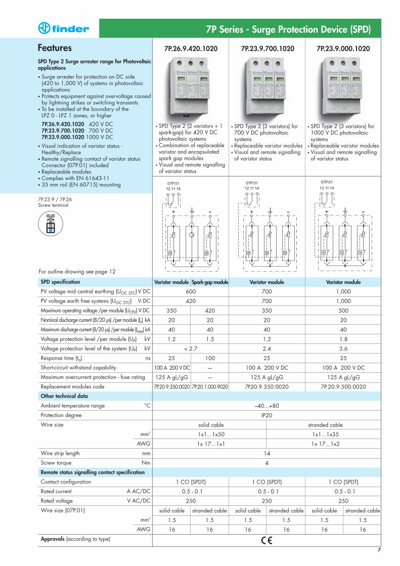
7P.26.9.420.1020 7P.23.9.700.1020 7P.23.9.000.1020
SPD specification
PV voltage mid central earthing (UOC STC)V DC
PV voltage earth free systems (UOC STC) V DC
Maximum operating voltage /per module (UCPV) V DC
Nominal discharge current (8/20 μs) /per module (In) kA
Maximum discharge current (8/20 μs) /per module (Imax) kA
Voltage protection level /per module (UP) kV
Voltage protection level of the system (UP) kV
Response time (ta) ns
Short-circuit withstand capability
Maximum overcurrent protection - fuse rating
Replacement modules code
Other technical data
Ambient temperature range °C
Protection degree
Wire size
mm2
AWG
Wire strip length mm
Screw torque Nm
Remote status signalling contact specification
Contact configuration
Rated current A AC/DC
Rated voltage V AC/DC
Wire size (07P.01)
mm2
AWG
Approvals (according to type)
7
FeaturesSPD Type 2 Surge arrester range for Photovoltaic applications
• Surge arrester for protection on DC side (420 to 1,000 V) of systems in photovoltaic applications
• Protects equipment against overvoltage causedby lightning strikes or switching transients
• To be installed at the boundary of the LPZ 0 - LPZ 1 zones, or higher
7P.26.9.420.1020 420 V DC7P.23.9.700.1020 700 V DC7P.23.9.000.1020 1000 V DC
• Visual indication of varistor status - Healthy/Replace
• Remote signalling contact of varistor statusConnector (07P.01) included
• Replaceable modules• Complies with EN 61643-11• 35 mm rail (EN 60715) mounting
Varistor module Spark-gap module Varistor module Varistor module
600 700 1,000
420 700 1,000
350 420 350 500
20 20 20 20
40 40 40 40
1.2 1.5 1.2 1.8
< 2.7 2.4 3.6
25 100 25 25
100 A 200 V DC — 100 A 200 V DC 100 A 200 V DC
125 A gL/gG — 125 A gL/gG 125 A gL/gG
7P.20.9.350.0020 7P.20.1.000.9020 7P.20.9.350.0020 7P.20.9.500.0020
–40...+80
IP20
solid cable stranded cable
1x1...1x50 1x1...1x35
1x 17...1x1 1x 17...1x2
14
4
1 CO (SPDT) 1 CO (SPDT) 1 CO (SPDT)
0.5 - 0.1 0.5 - 0.1 0.5 - 0.1
250 250 250
solid cable stranded cable solid cable stranded cable solid cable stranded cable
1.5 1.5 1.5 1.5 1.5 1.5
16 16 16 16 16 16
For outline drawing see page 12
7P.23.9 / 7P.26Screw terminal
• SPD Type 2 (2 varistors + 1 spark-gap) for 420 V DC photovoltaic systems
• Combination of replaceable varistor and encapsulated spark gap modules
• Visual and remote signalling of varistor status
• SPD Type 2 (3 varistors) for 1000 V DC photovoltaic systems
• Replaceable varistor modules• Visual and remote signalling of varistor status
• SPD Type 2 (3 varistors) for 700 V DC photovoltaic systems
• Replaceable varistor modules• Visual and remote signalling of varistor status
7P Series - Surge Protection Device (SPD)
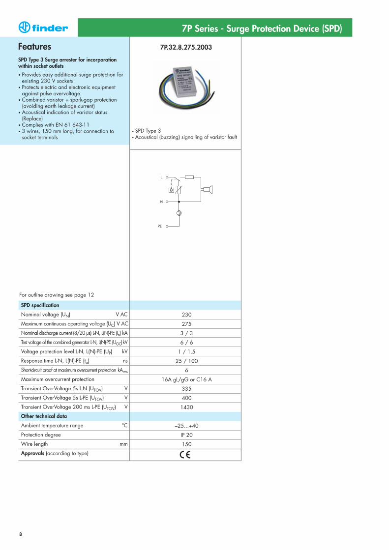
7P.32.8.275.2003
• SPD Type 3• Acoustical (buzzing) signalling of varistor fault
SPD specification
Nominal voltage (UN) V AC
Maximum continuous operating voltage (UC) V AC
Nominal discharge current (8/20 μs) L-N, L(N)-PE (In) kA
Test voltage of the combined generator L-N, L(N)-PE (UOC)kV
Voltage protection level L-N, L(N)-PE (UP) kV
Response time L-N, L(N)-PE (ta) ns
Short-circuit proof at maximum overcurrent protection kArms
Maximum overcurrent protection
Transient OverVoltage 5s L-N (UTOV) V
Transient OverVoltage 5s L-PE (UTOV) V
Transient OverVoltage 200 ms L-PE (UTOV) V
Other technical data
Ambient temperature range °C
Protection degree
Wire length mm
Approvals (according to type)
FeaturesSPD Type 3 Surge arrester for incorporationwithin socket outlets
• Provides easy additional surge protection for existing 230 V sockets
• Protects electric and electronic equipment against pulse overvoltage
• Combined varistor + spark-gap protection (avoiding earth leakage current)
• Acoustical indication of varistor status (Replace)
• Complies with EN 61 643-11• 3 wires, 150 mm long, for connection to
socket terminals
7P Series - Surge Protection Device (SPD)
230
275
3 / 3
6 / 6
1 / 1.5
25 / 100
6
16A gL/gG or C16 A
335
400
1430
–25...+40
IP 20
150
8
For outline drawing see page 12
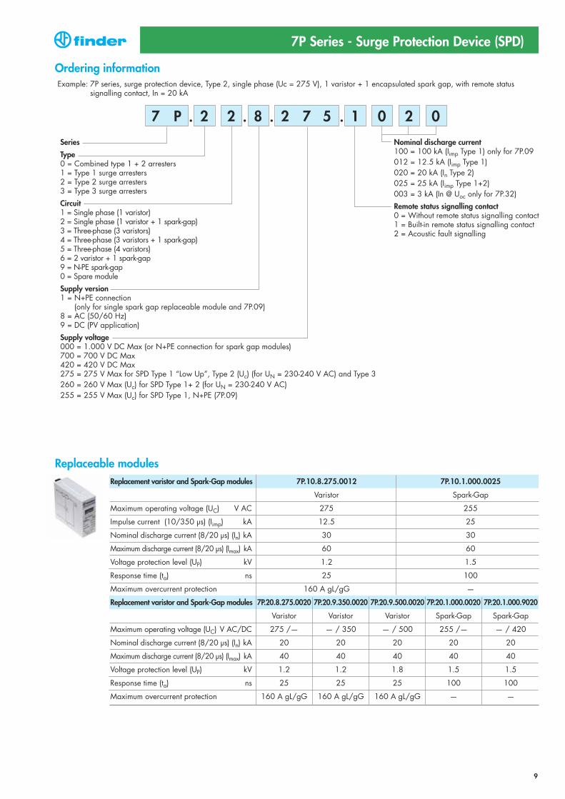
Example: 7P series, surge protection device, Type 2, single phase (Uc = 275 V), 1 varistor + 1 encapsulated spark gap, with remote status signalling contact, In = 20 kA
Nominal discharge current100 = 100 kA (Iimp Type 1) only for 7P.09012 = 12.5 kA (Iimp Type 1)020 = 20 kA (In Type 2)025 = 25 kA (Iimp Type 1+2)003 = 3 kA (In @ Uoc only for 7P.32)
Remote status signalling contact 0 = Without remote status signalling contact1 = Built-in remote status signalling contact2 = Acoustic fault signalling
Series
Type0 = Combined type 1 + 2 arresters1 = Type 1 surge arresters2 = Type 2 surge arresters3 = Type 3 surge arresters
Circuit1 = Single phase (1 varistor)2 = Single phase (1 varistor + 1 spark-gap)3 = Three-phase (3 varistors)4 = Three-phase (3 varistors + 1 spark-gap)5 = Three-phase (4 varistors)6 = 2 varistor + 1 spark-gap9 = N-PE spark-gap0 = Spare module
Supply version1 = N+PE connection
(only for single spark gap replaceable module and 7P.09)8 = AC (50/60 Hz)9 = DC (PV application)
Supply voltage 000 = 1.000 V DC Max (or N+PE connection for spark gap modules)700 = 700 V DC Max420 = 420 V DC Max275 = 275 V Max for SPD Type 1 “Low Up”, Type 2 (Uc) (for UN = 230-240 V AC) and Type 3260 = 260 V Max (Uc) for SPD Type 1+ 2 (for UN = 230-240 V AC)255 = 255 V Max (Uc) for SPD Type 1, N+PE (7P.09)
2 2 1 08 2 0
Ordering information
. . . .2 7 57 P
7P Series - Surge Protection Device (SPD)
9
Replacement varistor and Spark-Gap modules 7P.10.8.275.0012 7P.10.1.000.0025
Varistor Spark-Gap
Maximum operating voltage (UC) V AC 275 255
Impulse current (10/350 μs) (Iimp) kA 12.5 25
Nominal discharge current (8/20 μs) (In) kA 30 30
Maximum discharge current (8/20 μs) (Imax) kA 60 60
Voltage protection level (UP) kV 1.2 1.5
Response time (ta) ns 25 100
Maximum overcurrent protection 160 A gL/gG —
Replacement varistor and Spark-Gap modules 7P.20.8.275.0020 7P.20.9.350.0020 7P.20.9.500.0020 7P.20.1.000.0020 7P.20.1.000.9020
Varistor Varistor Varistor Spark-Gap Spark-Gap
Maximum operating voltage (UC) V AC/DC 275 /— — / 350 — / 500 255 /— — / 420
Nominal discharge current (8/20 μs) (In) kA 20 20 20 20 20
Maximum discharge current (8/20 μs) (Imax) kA 40 40 40 40 40
Voltage protection level (UP) kV 1.2 1.2 1.8 1.5 1.5
Response time (ta) ns 25 25 25 100 100
Maximum overcurrent protection 160 A gL/gG 160 A gL/gG 160 A gL/gG — —
Replaceable modules

7P Series - Surge Protection Device (SPD) - Dimensional data
Outline drawingsType 7P.09Screw terminal
Type 7P.01Screw terminal
10
Type 7P.02Screw terminal
Type 7P.04Screw terminal
Type 7P.03Screw terminal
11
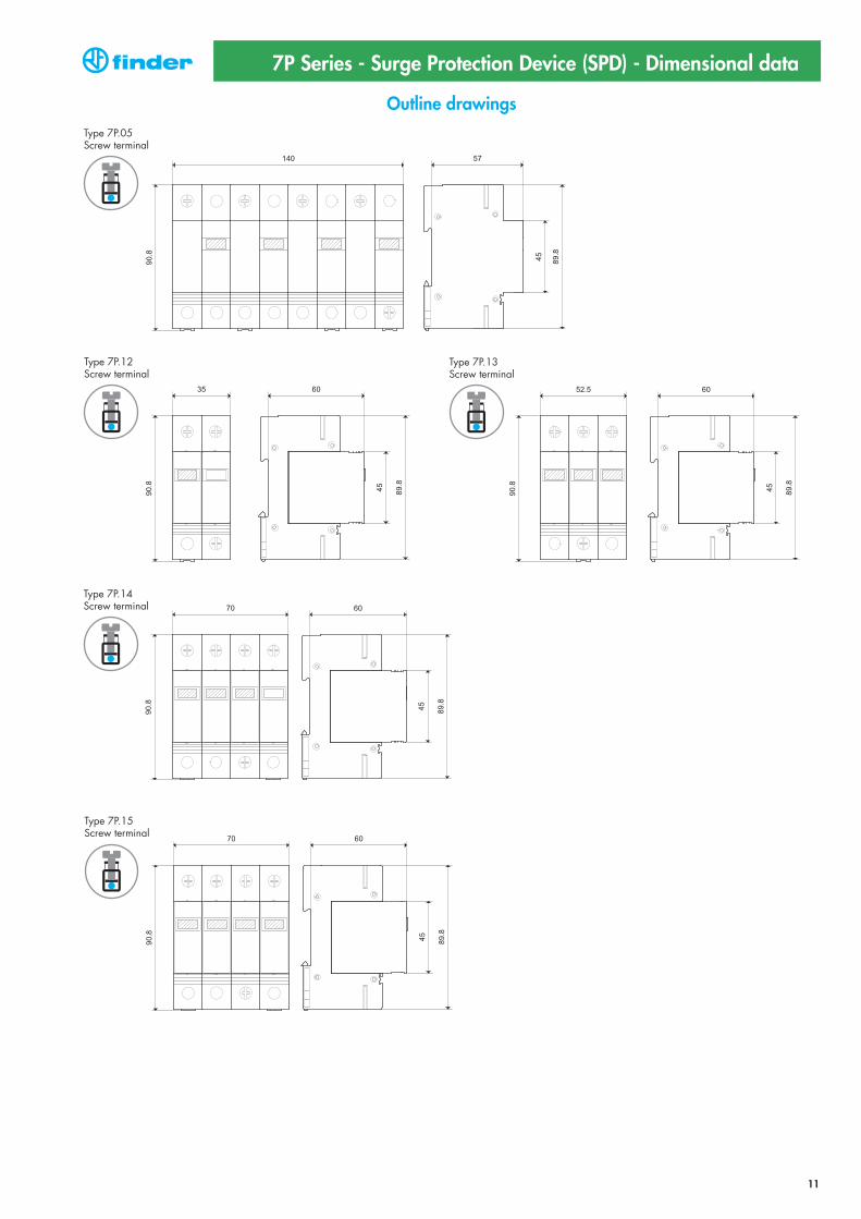
7P Series - Surge Protection Device (SPD) - Dimensional data
Outline drawingsType 7P.05Screw terminal
Type 7P.12Screw terminal
Type 7P.13Screw terminal
Type 7P.14Screw terminal
Type 7P.15Screw terminal

12
7P Series - Surge Protection Device (SPD) - Dimensional data
Outline drawingsType 7P.21Screw terminal
Type 7P.22Screw terminal
Type 7P.23.8Screw terminal
Type 7P.23.9Screw terminal
Type 7P.24Screw terminal
Type 7P.25Screw terminal
Type 7P.26Screw terminal
Type 7P.20Replaceable module
Type 7P.32
07P.01Connector
13
7P Series - Surge Protection Device (SPD)
Installation example - SPD Type 1 + 2
TT-SINGLE PHASE SYSTEM - SPD UP-STREAM OF RCD TT-SINGLE PHASE SYSTEM - SPD UP-STREAM OF RCD
TT THREE PHASE SYSTEM - SPD UP-STREAM OF RCDTT-THREE PHASE SYSTEM - SPD UP-STREAM OF RCD
14
7P Series - Surge Protection Device (SPD)
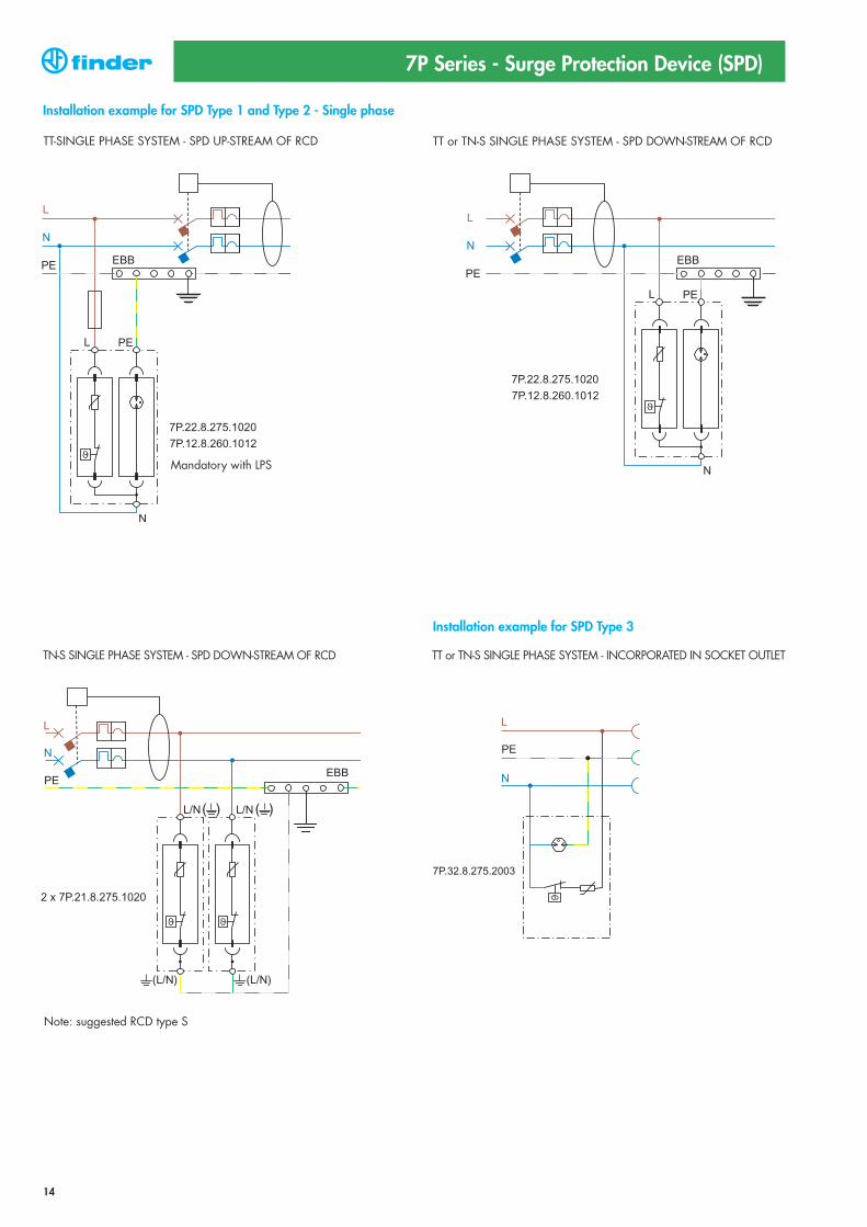
Installation example for SPD Type 1 and Type 2 - Single phase
Installation example for SPD Type 3
TT-SINGLE PHASE SYSTEM - SPD UP-STREAM OF RCD TT or TN-S SINGLE PHASE SYSTEM - SPD DOWN-STREAM OF RCD
TT or TN-S SINGLE PHASE SYSTEM - INCORPORATED IN SOCKET OUTLETTN-S SINGLE PHASE SYSTEM - SPD DOWN-STREAM OF RCD
Note: suggested RCD type S
Mandatory with LPS
15
7P Series - Surge Protection Device (SPD)
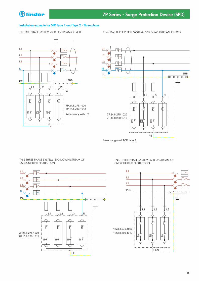
Installation example for SPD Type 1 and Type 2 - Three phase
TT-THREE PHASE SYSTEM - SPD UP-STREAM OF RCD TT or TN-S THREE PHASE SYSTEM - SPD DOWN-STREAM OF RCD
TN-S THREE PHASE SYSTEM - SPD DOWN-STREAM OF OVERCURRENT PROTECTION
TN-C THREE PHASE SYSTEM - SPD UP-STREAM OF OVERCURRENT PROTECTION
Note: suggested RCD type S
Mandatory with LPS

16
7P Series - Surge Protection Device (SPD)
Installation examples - photovoltaic
17
7P Series - Surge Protection Device (SPD)
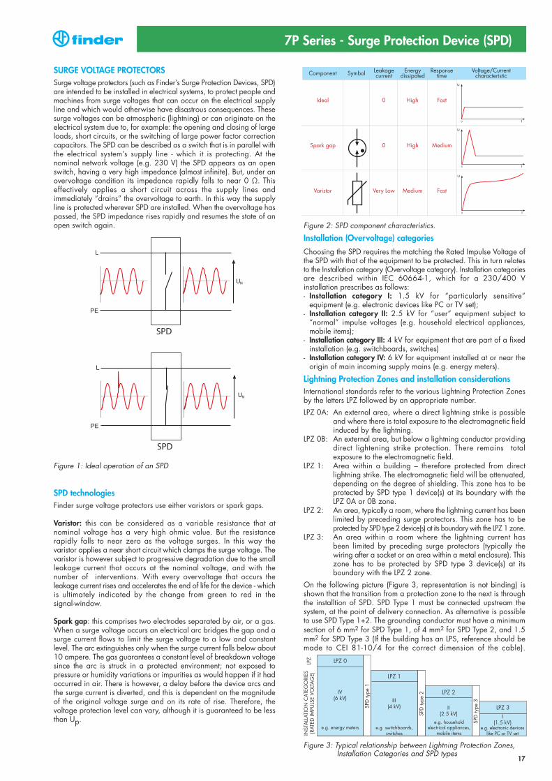
SURGE VOLTAGE PROTECTORSSurge voltage protectors (such as Finder’s Surge Protection Devices, SPD)are intended to be installed in electrical systems, to protect people andmachines from surge voltages that can occur on the electrical supplyline and which would otherwise have disastrous consequences. Thesesurge voltages can be atmospheric (lightning) or can originate on the electrical system due to, for example: the opening and closing of largeloads, short circuits, or the switching of large power factor correctioncapacitors. The SPD can be described as a switch that is in parallel withthe electrical system’s supply line - which it is protecting. At the nominal network voltage (e.g. 230 V) the SPD appears as an openswitch, having a very high impedance (almost infinite). But, under anovervoltage condition its impedance rapidly falls to near 0 Ω. This effectively applies a short circuit across the supply lines and immediately “drains” the overvoltage to earth. In this way the supplyline is protected wherever SPD are installed. When the overvoltage haspassed, the SPD impedance rises rapidly and resumes the state of anopen switch again.
Figure 1: Ideal operation of an SPD
SPD technologiesFinder surge voltage protectors use either varistors or spark gaps.
Varistor: this can be considered as a variable resistance that at nominal voltage has a very high ohmic value. But the resistance rapidly falls to near zero as the voltage surges. In this way the varistor applies a near short circuit which clamps the surge voltage. Thevaristor is however subject to progressive degradation due to the smallleakage current that occurs at the nominal voltage, and with the number of interventions. With every overvoltage that occurs the leakage current rises and accelerates the end of life for the device - whichis ultimately indicated by the change from green to red in the signal-window.
Spark gap: this comprises two electrodes separated by air, or a gas.When a surge voltage occurs an electrical arc bridges the gap and asurge current flows to limit the surge voltage to a low and constant level. The arc extinguishes only when the surge current falls below about10 ampere. The gas guarantees a constant level of breakdown voltagesince the arc is struck in a protected environment; not exposed to pressure or humidity variations or impurities as would happen if it hadoccurred in air. There is however, a delay before the device arcs andthe surge current is diverted, and this is dependent on the magnitudeof the original voltage surge and on its rate of rise. Therefore, the voltage protection level can vary, although it is guaranteed to be lessthan Up.
Figure 2: SPD component characteristics.
Installation (Overvoltage) categories
Choosing the SPD requires the matching the Rated Impulse Voltage ofthe SPD with that of the equipment to be protected. This in turn relatesto the Installation category (Overvoltage category). Installation categoriesare described within IEC 60664-1, which for a 230/400 V installation prescribes as follows:- Installation category I: 1.5 kV for “particularly sensitive”
equipment (e.g. electronic devices like PC or TV set);- Installation category II: 2.5 kV for “user” equipment subject to
“normal” impulse voltages (e.g. household electrical appliances,mobile items);
- Installation category III: 4 kV for equipment that are part of a fixedinstallation (e.g. switchboards, switches)
- Installation category IV: 6 kV for equipment installed at or near theorigin of main incoming supply mains (e.g. energy meters).
Lightning Protection Zones and installation considerationsInternational standards refer to the various Lightning Protection Zonesby the letters LPZ followed by an appropriate number.
LPZ 0A: An external area, where a direct lightning strike is possibleand where there is total exposure to the electromagnetic fieldinduced by the lightning.
LPZ 0B: An external area, but below a lightning conductor providingdirect lightening strike protection. There remains total exposure to the electromagnetic field.
LPZ 1: Area within a building – therefore protected from direct lightning strike. The electromagnetic field will be attenuated,depending on the degree of shielding. This zone has to be protected by SPD type 1 device(s) at its boundary with the LPZ 0A or 0B zone.
LPZ 2: An area, typically a room, where the lightning current has beenlimited by preceding surge protectors. This zone has to be protected by SPD type 2 device(s) at its boundary with the LPZ 1 zone.
LPZ 3: An area within a room where the lightning current hasbeen limited by preceding surge protectors (typically thewiring after a socket or an area within a metal enclosure). Thiszone has to be protected by SPD type 3 device(s) at itsboundary with the LPZ 2 zone.
On the following picture (Figure 3, representation is not binding) isshown that the transition from a protection zone to the next is throughthe installtion of SPD. SPD Type 1 must be connected upstream the system, at the point of delivery connection. As alternative is possibleto use SPD Type 1+2. The grounding conductor must have a minimumsection of 6 mm2 for SPD Type 1, of 4 mm2 for SPD Type 2, and 1.5mm2 for SPD Type 3 (If the building has an LPS, reference should bemade to CEI 81-10/4 for the correct dimension of the cable).
Figure 3: Typical relationship between Lightning Protection Zones, Installation Categories and SPD types
Component
Ideal
Spark gap
Varistor
0
0
Very Low
High
High
Medium
Fast
Medium
Fast
Symbol Leakagecurrent
Energydissipated
Responsetime
Voltage/Currentcharacteristic
INST
ALL
ATIO
N C
ATEG
ORI
ES(R
ATED
IMPU
LSE
VOLT
AG
E)LP
Z
SPD
type
1
SPD
type
2
SPD
type
3
e.g. energy meters
LPZ 0
IV(6 kV) III
(4 kV) II(2.5 kV) I
(1.5 kV)
LPZ 1
LPZ 2
LPZ 3
e.g. electronic deviceslike PC or TV set
e.g. household electrical appliances,
mobile itemse.g. switchboards,
switches

18
7P Series - Surge Protection Device (SPD)
Rated values and marking common to all SPD[Uc] Maximum continuous operating voltage: Under this voltage the SPDis guaranteed to appear as an “open switch”. This voltage is normallyat least equal to the nominal supply voltage (UN) + 10%. For the Finder SPD, Uc is specified as 275 V.
[Up] Voltage protection level: This is the highest voltage level seen acrossthe SPD during its intervention. For example, for Finder SPD Type 2, thismeans that a 4kV overvoltage would be limited by the SPD to a maximum 1.2 kV. Consequently, electronic devices such as PC, TV,stereo, etc. are protected - as their own internal protection will handleovervoltages up to 1.5 kV. To better understand this concept; imagine that the SPD is a switch inseries a low resistance. In the case of an overvoltage the switch closes and all the current goes through the resistance. According toOhm’s law the voltage developed across the resistance will be this resistance x the current (V = R x I), and will be limited to < Up.
Figure 4: Overvoltage limiting
Short circuit proof: A further characteristic, not normally marked on the product but important for its correct installation, is the Short circuit proof at maximum overcurrent protection. This is the maximum short-circuit current that the SPD is able to withstand when it is installed with additional maximum overcurrent protection - such as a fuse rated in accordance with the value stated under the SPD specification. Consequentely the maximum prospective short-circuit current of thesystem at the point of installation of the SPD must not exceed this value.
Rated vaules and marking of SPD Type 1SPD Type 1 must be connected upstream the system, at the point of delivery of power energy. SPD protects building and people from therisk of direct lightning (fire and death) and are characterized by:
[Iimp10/350] Impulse current: Iimp corresponds to the peak value ofa 10/350 μs current impulse waveform. This waveform represents adirect lightning strike and is used in tests to prove the performance ofSPD type 1 devices.
Figure 5: 10/350 μs current waveform
Comparison of the waveforms in figures 5 and 6 shows the much higher energy content controlled by the type 1 SPD.
[In8/20] Nominal discharge current: The peak current (and waveformshape) through the SPD under conditions prescribed by EN 62305 torepresent the surge current as a consequence of a lightning strike to theelectric supply line.
Figure 6: 8/20 μs current waveform
Rated values and marking of SPD Type 2SPD Type 2 devices are designed to remove all the overvoltage fromsupply circuits that are not likely to be directly hit by lightning. SPD Type2 are connected downstream SPD Type 1 or SPD Type 1+2, (minimumdistance 1 m) and they protect machine and tools connected to the grindand reduce the risk of economic loss.SPD Type 2 are characterized by:
[In8/20] Nominal discharge current: The peak current (and waveformshape) through the SPD under conditions prescribed by EN 62305 torepresent the surge current as a consequence of a lightning strike to theelectric supply line.
[Imax8/20] Maximum discharge current: Peak value of the highest current of a 8/20μs waveform that an SPD can discharge at least oncewithout breaking.
Rated values and marking of SPD Type 3SPD type 3 devices are used to protect the end user from overvoltage.They may be installed in supply networks where SDP types 1 and/or2 already exist. They can be installed in fixed or mobile sockets andhave the following characteristic parameters.
Uoc: test voltage. This is the peak value of the no load voltage of thecombined test-generator; this has a waveform of 1.2/50 μs(figure 7) and can supply at the same time current with waveform 8/20μs (figure 6).
Figure 7: 1.2/50 μs voltage waveform
Suggestion for the connectionThe correct connection of SPD requires a shortest as possible connection to the equipotential local bar, to which are connected PEcables of the equipment to be protected. From the equipotential local bar there is a connection to the EBB. The phase wiring remains appropriate to the load.
I (peak)
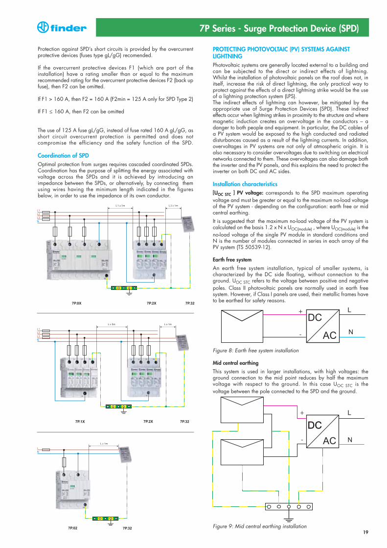
PROTECTING PHOTOVOLTAIC (PV) SYSTEMS AGAINST LIGHTNINGPhotovoltaic systems are generally located external to a building andcan be subjected to the direct or indirect effects of lightning.Whilst the installation of photovoltaic panels on the roof does not, initself, increase the risk of direct lightning, the only practical way to protect against the effects of a direct lightning strike would be the useof a lightning protection system (LPS).The indirect effects of lightning can however, be mitigated by the appropriate use of Surge Protection Devices (SPD). These indirect effects occur when lightning strikes in proximity to the structure and wheremagnetic induction creates an overvoltage in the conductors – a danger to both people and equipment. In particular, the DC cables ofa PV system would be exposed to the high conducted and radiated disturbances caused as a result of the lightning currents. In addition,overvoltages in PV systems are not only of atmospheric origin. It is also necessary to consider overvoltages due to switching on electricalnetworks connected to them. These overvoltages can also damage boththe inverter and the PV panels, and this explains the need to protect theinverter on both DC and AC sides.
Installation characteristics[UOC STC ] PV voltage: corresponds to the SPD maximum operatingvoltage and must be greater or equal to the maximum no-load voltageof the PV system - depending on the configuration: earth free or midcentral earthing.
It is suggested that the maximum no-load voltage of the PV system is calculated on the basis 1.2 x N x UOC(module) , where UOC(module) is theno-load voltage of the single PV module in standard conditions and N is the number of modules connected in series in each array of thePV system (TS 50539-12).
Earth free system
An earth free system installation, typical of smaller systems, ischaracterized by the DC side floating, without connection to theground. UOC STC refers to the voltage between positive and negativepoles. Class II photovoltaic panels are normally used in earth free system. However, if Class I panels are used, their metallic frames haveto be earthed for safety reasons.
Figure 8: Earth free system installation
Mid central earthing
This system is used in larger installations, with high voltages: theground connection to the mid point reduces by half the maximum voltage with respect to the ground. In this case UOC STC is the voltage between the pole connected to the SPD and the ground.
Figure 9: Mid central earthing installation
7P Series - Surge Protection Device (SPD)
Protection against SPD’s short circuits is provided by the overcurrent protective devices (fuses type gL/gG) recomended.
If the overcurrent protective devices F1 (which are part of the installation) have a rating smaller than or equal to the maximum recommended rating for the overcurrent protective devices F2 (back upfuse), then F2 can be omitted.
If F1 > 160 A, then F2 = 160 A (F2min = 125 A only for SPD Type 2)
If F1 ≤ 160 A, then F2 can be omitted
The use of 125 A fuse gL/gG, instead of fuse rated 160 A gL/gG, asshort circuit overcurrent protection is permitted and does not compromise the efficiency and the safety function of the SPD.
Coordination of SPDOptimal protection from surges requires cascaded coordinated SPDs.Coordination has the purpose of splitting the energy associated withvoltage across the SPDs and it is achieved by introducing an impedance between the SPDs, or alternatively, by connecting them using wires having the minimum length indicated in the figures below, in order to use the impedance of its own conductor.
19
20
7P Series - Surge Protection Device (SPD)
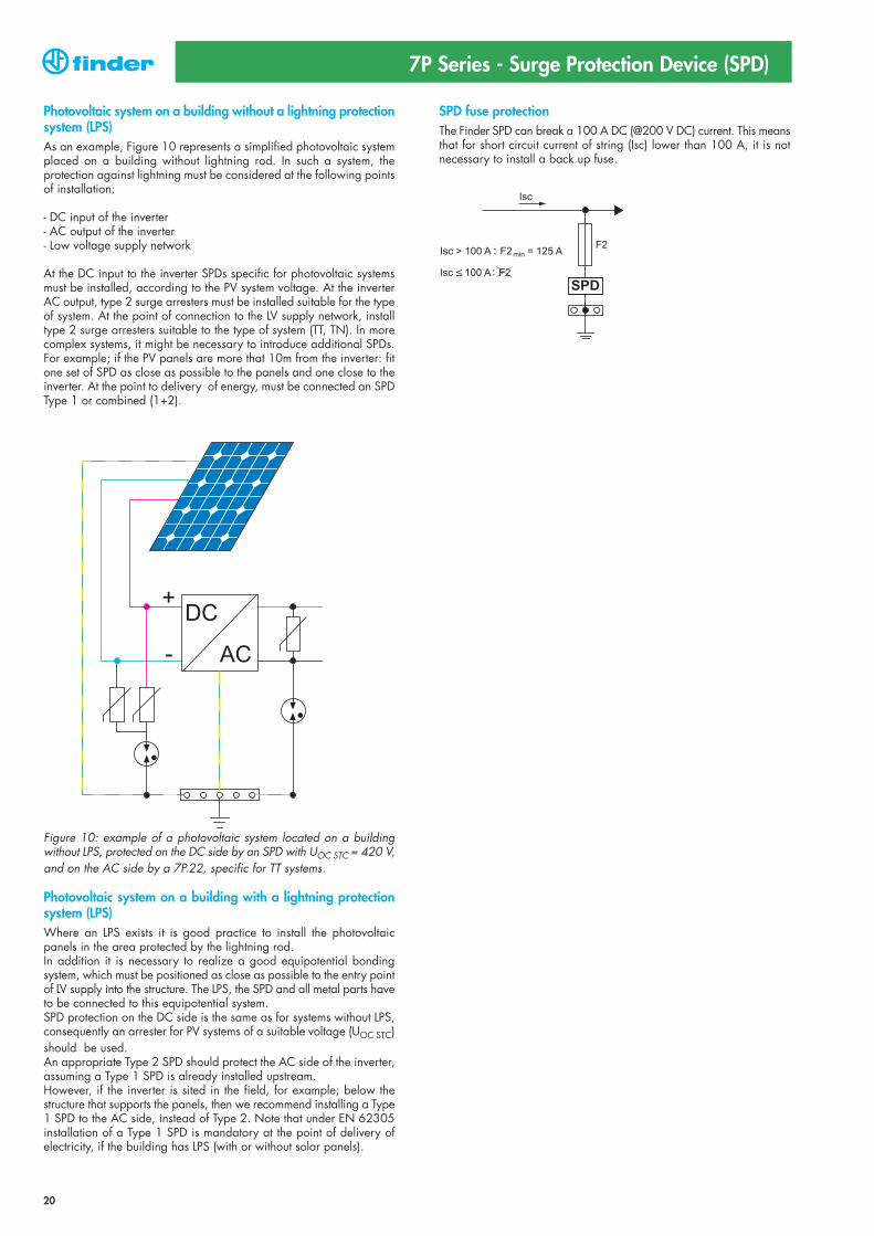
Photovoltaic system on a building without a lightning protectionsystem (LPS)As an example, Figure 10 represents a simplified photovoltaic systemplaced on a building without lightning rod. In such a system, the protection against lightning must be considered at the following pointsof installation:
- DC input of the inverter- AC output of the inverter- Low voltage supply network
At the DC input to the inverter SPDs specific for photovoltaic systemsmust be installed, according to the PV system voltage. At the inverterAC output, type 2 surge arresters must be installed suitable for the typeof system. At the point of connection to the LV supply network, installtype 2 surge arresters suitable to the type of system (TT, TN). In morecomplex systems, it might be necessary to introduce additional SPDs.For example; if the PV panels are more that 10m from the inverter: fitone set of SPD as close as possible to the panels and one close to theinverter. At the point to delivery of energy, must be connected an SPDType 1 or combined (1+2).
Figure 10: example of a photovoltaic system located on a building without LPS, protected on the DC side by an SPD with UOC STC = 420 V,and on the AC side by a 7P.22, specific for TT systems.
Photovoltaic system on a building with a lightning protection system (LPS)Where an LPS exists it is good practice to install the photovoltaic panels in the area protected by the lightning rod.In addition it is necessary to realize a good equipotential bonding system, which must be positioned as close as possible to the entry pointof LV supply into the structure. The LPS, the SPD and all metal parts haveto be connected to this equipotential system.SPD protection on the DC side is the same as for systems without LPS,consequently an arrester for PV systems of a suitable voltage (UOC STC)should be used.An appropriate Type 2 SPD should protect the AC side of the inverter,assuming a Type 1 SPD is already installed upstream. However, if the inverter is sited in the field, for example; below the structure that supports the panels, then we recommend installing a Type1 SPD to the AC side, instead of Type 2. Note that under EN 62305installation of a Type 1 SPD is mandatory at the point of delivery of electricity, if the building has LPS (with or without solar panels).
SPD fuse protectionThe Finder SPD can break a 100 A DC (@200 V DC) current. This meansthat for short circuit current of string (Isc) lower than 100 A, it is not necessary to install a back up fuse.