Embed Size (px)
Citation preview

The Control of Multiple A ctuators using Single IEHE C Pump/Motor
Teshale Bekele, Rafael Åman and Heikki Handroos Laboratory of Intelligent Machines, Lappeenranta University of Technology (LUT) Skinnarilankatu 34,53850 Lappeenranta, Finland, E-Mail: [email protected]
Abstract The awareness and concern of our environment together with legislation have set more
and more tightening demands for energy efficiency of non-road mobile machinery
(NRMM). Integrated electro-hydraulic energy converter (IEHEC) has been developed in
Lappeenranta University of Technology (LUT) /1/. The elimination of resistance flow, and
the recuperation of energy makes it very efficient alternative. The difficulties of IEHEC
machine to step to the market has been the requirement of one IEHEC machine per one
actuator. The idea is to switch IEHEC between two actuators of log crane using fast
on/off valves. The control system architecture is introduced. The system has been
simulated in co-simulation using Simulink/Mevea. The simulated responses of pump-
controlled system is compared to the responses of the conventional valve-controlled
system.
KEYWORDS: IEHEC pump/motor, pump-controlled system, non-road mobile
machinery, fast on/off valve.
1. Introduction
In hybrid technology it is possible to increase the efficiency of the vehicle power
transmission system. It is often also possible to maintain the performance of the vehicle
even when the original internal combustion engine is replaced by a remarkably smaller
one /2/.Improvement of the efficiency of the working hydraulics has an important role
when the target is to reduce working machine’s energy consumption /3/. The new control
method for electro-hydraulic energy converter (IEHEC), (see Fig. 3) is introduced. This
machine has a high power density and allows transformation of electrical energy into
hydraulic energy and vice versa /1/.
There are three major features of IEHEC machine that makes it highly efficient over the
traditional valve control system. The first one: the elimination of resistance flow apparent
in throttle orifices which is known to be the basic problem of load sensing control system.
Group A - Digital Hydraulics | Paper A-4 73
A number of modifications to load-sensing actuation have been proposed by researchers
all over the world in order to minimize metering losses /4/, /5/, /6/, /7/, & /8/. It can be
noted that the control for this specific system is complicated and large number of valves
are required to realize every operating mode. All mentioned improvements on load
sensing system reduces the metering losses but could not eliminate the losses.
Second: the replacement of hydraulic pipelines by electric cable. In non-road mobile
machinery, the fluid power transmission lines are flexible hoses and pipes of small
diameter which causes considerable power losses. In the electric cables the losses
because of their internal resistances are apparent but negligible in comparison with the
losses apparent in the hydraulic transmission lines /9/. In place of using long fluid power
transmission lines, the end actuators can be supplied by the IEHEC, placed directly close
to them.
Thirdly: the recuperation of energy in the form of electricity. Suitable place for this
application in heavy mobile machines are all actuators that carry out work cycle in which
the kinetic and potential energy is available for recovery e.g. lifting cylinders in cranes,
grippers that tend to open by the payload mass and gravity /9/.
The prototype of IEHEC was tested by efficiency and characteristic measurements /10/.
The testing of functionality of IEHEC as a component of working machine and finding of
suitable application area has been the next step. Development of control interface for
hardware-in-the-loop (HIL) simulation of IEHEC has been carried out /11/. Experiment
has been done on applicability (functionality) and efficiency of IEHEC machine in single
actuator /12/.
In this paper, design of the fluid power circuit has been done on the applicability of single
IEHEC machine for multiple actuators. The actuators are separated by using fast on/off
valves. Two different size of asymmetric differential cylinders of log crane have been
used in the experimental set-up. To control the cylinder movement the direction of
rotation and the rotational speed of the IEHEC pump/motor is alternated using the
frequency converter. The experimental set-up has been designed and assembled as
shown in Fig. 1. The circuit diagram of designed fluid power circuit is shown in Fig. 3.
The experimental tests have not been carried out in the physical experimental set-up.
Instead, the virtual prototypes modelled in Mevea software /23/ and in co-simulation
Simulink/Mevea have been used to test the applicability. The attained results have been
compared with the conventional valve controlled system that has been modelled using
Mevea software.
74 10th International Fluid Power Conference | Dresden 2016

Figure 1: The Log Crane test setup
2. IEHEC
The integrated electro-hydraulic energy converter (IEHEC) is the principal component of
the studied multiple actuator system. The designed IEHEC consists of a bent-axis piston
hydraulic machine of 63 cm3/rev and an integrated tooth-coil permanent magnet
synchronous machine, which operates on the same shaft (see Fig. 2) /10/.
The designed solution of IEHEC allows considerably high space savings in the mobile
environment. The compact design of the integrated electrical machine imposes the use
of efficient liquid cooling. The working hydraulic fluid can be used as cooling media. The
hydraulic cooling system increases the power density which allows to use less active
electrical and magnetic materials in the construction of the electrical machine /10/.
Figure 2: prototype of IEHEC
The IEHEC of 26 kW has originally been designed for the power of 45 kW. It weighs only
43 % of a standard 45 kW induction motor coupled with the similar hydraulic machine
and needs only 35 % of the installation length of standard setup. The maximum efficiency
of the prototype is 90% in pumping mode and 86% in regenerating mode /10/.
Group A - Digital Hydraulics | Paper A-4 75

Parameters Value nominal power Flow rate pressure voltage nominal current coolant flow
26kW up to 180 l/min up to 400 bar 400 V 44 A 4 l/m @70o c
Table 1: Parameters of IEHEC /10/
3. Displacement Controlled Hybrid Actuator system
The studied circuit diagram shown in Fig. 3, is electro-hydraulic hybrid actuator system.
The system in question is a pump controlled fluid power system using displacement
control (DC). The control of actuator motion in DC actuation system uses the pump
displacement.
Highly efficient displacement controlled actuation has been studied in /13/. The basis for
the advantages of DC actuation reside in the complete elimination of resistance control.
Figure 3: The studied system circuit diagram
In this system differential volume and volumetric losses are balanced on the low pressure
side. Low pressure is given by the characteristics of low pressure source pump and
accumulator and limited by the pressure relief valve. Two pilot operated check valves
ensure that the low pressure level is always connected to the low pressure of the cylinder.
This depends on the operating quadrant. The four quadrant operation of differential
cylinder in DC solution for linear servo actuator has been proposed in /14/ and /15/. In
this test the low pressure is set to pset=20 bar.
The hydraulic pump-motor used in this system is directly driven by the electrical motor-
generator controlled by a frequency convertor in reference to the actuators piston rod
76 10th International Fluid Power Conference | Dresden 2016

velocities. Hence, the system is capable to recover the energy released in motoring
quadrants and stored into batteries.
The switching of the IEHEC machine between actuators (i.e. lifting and tilting actuators
of log crane) as shown in the Fig.3 is managed by fast on/off solenoid valves. In the
studied system the piston rods of two actuators are initially in fully retracted (lifting) and
in fully extended (tilting) positions. The different position of the actuator piston rod would
require different operating direction of the IEHEC machine which in turns the system
cannot operate for two actuators at a time. This problem can be managed by reverting
the tilting cylinder ports and, thus, the extension of lifting and retraction of tilting would
operate in same direction of rotation of IEHEC. Thus the switching of the actuator can
be managed easily by the fast on/off valves.
4. Modelling of the studied circuit
The opening of the fast on/off 2/2 directional valves are solved using first order dynamics,
Eq. (1).
(1)
Similarly, for the angular speed of the electrical machine
(2)
The pump volume flow is calculated using, Eq. (3)
(3)
And, the cylinder flow is
(4)
The pressure build up in the volumes can be described by the continuity equations of
Merritt, Eq. (5). /16/.
∆ (5)
The compressional volume flow can be described by equation (6).
∆ ∑ ∑ ∑ (6)
, where is externally supplied volume flow into and out of the volume (i.e. accumulator
and actuator flow).
Group A - Digital Hydraulics | Paper A-4 77

The volume flows in and out of each volume can be described in terms corresponding
pressure drop by Eq. (7).
∆ (7)
The volume flows of every orifices in the circuit is approximated by Eq. (7). The
conditional statements and smoothening function have been used to avoid numerical
problems in the simulation.
The force produced by the cylinder can be calculated using the chamber pressures and
the cylinder and piston areas as shown in Eq. (8).
(8)
The oil volume Voil of the pressure accumulator is described using Eq. (9).
(9)
The volume of the gas Vgas is then the differential of maximum volume of pressure vessel
Vmax and oil volume.
(10)
The gas pressure is solved using energy balance equation, Eq. (11).
(11)
H=1*10-5 s Cd=0.6 g = 9.81 m/s2 Llift =0.53 m Ltilt=0.78 m
Be=1.5*109 Pa ρ=860 kg/m3 dcv=20*10-3 m dp-lift=0.1 m dp-tilt=0.09 m
Uin=0…10 V b=5000 Ns/m dpcv=10*10-3 m dr-lift=0.056 m dr-tilt=0.056 m
Cv=4.12*10-8 ω=78.5 rad/s dpr=16*10-3 m T=20 s
Vp=1.003*10-5 m3/rad Vmax=5*10-3 m3
Table 2: Parameters used in the simulation
5. The control of the system
The IEHEC machine is controlled by the ABB ACS800M1 frequency converter. This
frequency controller works based on direct torque control (DTC) of the electrical motor.
For DTC, a typical torque response is 1 to 2 ms when operating below 40 Hz /17/. In
78 10th International Fluid Power Conference | Dresden 2016

simulation time constant of 32ms has been used to control the IEHEC machine. This
value is valid for variable displacement axial piston pump /18/.
The direction of the rotation of the IEHEC machine has to be alternated in order to
change the direction of the volume flow. Due to the combined inertia of rotor, pump shaft
and piston block, the build-up of the angular speed takes longer however, the torque
response is fast enough to build-up the angular speed. According to the design
parameter of the IEHEC machine the machine can speed up at no load from 0 to 1500
rpm by 25 ms. Thus, the used time constant is valid /18/.
The volume flow from/to the IEHEC unit to/from the system actuators are guided by
Rexroth 2/2 directional poppet valve of size NS6 with booster amplifier (fast on/off valves)
with the response time of 10ms, /19/ and /20/. One fast on/off valve allow the maximum
flow of 35 L/min at a pressure drop of 30 bar, and, thus, maximum Q=70 L/min by opening
two valves at a time is possible per actuator.
6. Conventional valve-controlled system modelled using Mevea software
The 3D model of the log crane is created the same way as the model in co-simulation.
The translational forces in the dummies are replaced by hydraulic pressure forces. All
the hydraulic components shown in the conventional valve controlled fluid power circuit
(see Fig. 6) are provided by Mevea software /23/. The forces (F1 and F2) are the external
forces applied on the cylinder rods due to the inertia of the log crane links. The selected
constant pressure pump builds-up 100 bar pressure in volume 1. The direction of the
flow is controlled by 4/3 solenoid directional control valve /21/. The solenoids are working
with a signal input of +/- 10 V. The pressure drop across the valve is 35 bar with nominal
flowrate of 40 l/min. The semi-empirical volume flow coefficient (Cv) is calculated using
Eq. 12. The time constant of a certain valve can be obtained from the Bode-diagram
provided by the valve manufactures. Typically, the frequency from the Bode-diagram is
chosen using the -45o phase shift /22/. The time constant can be calculated using Eq.
13.
c∆ /
(12)
(13)
Group A - Digital Hydraulics | Paper A-4 79
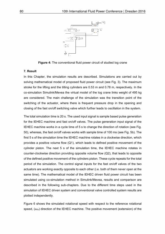
Figure 4: The conventional fluid power circuit of studied log crane
7. Result
In this Chapter, the simulation results are described. Simulations are carried out by
solving mathematical model of proposed fluid power circuit (see Fig. 3). The maximum
stroke for the lifting and the tilting cylinders are 0.53 m and 0.78 m, respectively. In the
co-simulation Simulink/Mevea the virtual model of the log crane links weight of 495 kg
are considered. The main challenge of the simulation was the transition point of the
switching of the actuator, where there is frequent pressure drop in the opening and
closing of the fast on/off switching valve which further leads to oscillation in the system.
The total simulation time is 20 s. The used input signal is sample based pulse generation
for the IEHEC machine and fast on/off valves. The pulse generation input signal of the
IEHEC machine works in a cycle time of 5 s to change the direction of rotation (see Fig.
50), whereas, the fast on/off valves works with sample time of 100 ms (see Fig. 5b). The
first 5 s of the simulation time the IEHEC machine rotates in a clockwise direction, which
provides a positive volume flow (Q1), which leads to defined positive movement of the
cylinder piston. The next 5 s of the simulation time, the IEHEC machine rotates in
counter-clockwise direction providing opposite volume flow (Q2), that leads to opposite
of the defined positive movement of the cylinders piston. These cycle repeats for the total
period of the simulation. The control signal inputs for the fast on/off valves of the two
actuators are working exactly opposite to each other (i.e. both of them never open at the
same time). The mathematical model of the IEHEC driven fluid power circuit has been
simulated using co-simulation method in Simulink/Mevea, results and comparison are
described in the following sub-chapters. Due to the different time steps used in the
simulation of IEHEC driven system and conventional valve controlled system results are
plotted independently.
Figure 6 shows the simulated rotational speed with respect to the reference rotational
speed, (ωin) direction of the IEHEC machine. The positive movement (extension) of the
80 10th International Fluid Power Conference | Dresden 2016

cylinders piston requires more volume flow than the negative movement (retraction).
Thus, the positive movement requires higher rotational speed. Note that the ωin is the
reference for the PI controller that sets the simulated rotational speed of shaft. The
vibration apparent in the graph is natural for this type of fast on/off control.
a)
b)
Figure 5: The control signal input: a) IEHEC machine b) Fast switching on/off valve
zoom out the first 2 s
Figure 6: The simulated angular speed and reference angular speed of IEHEC machine.
7.1. Co-simulation Simulink/Mevea results
The control signal used for the IEHEC machine and fast on/off switch valves are shown
in Fig. 5a and Fig. 5b. The inputs from Mevea simulation model of the log crane is used
instead of constant mass-load used in the Simulink model. Figure 7a shows the piston
position of the actuators. The switching of the IEHEC machine between the actuators
can be seen from the step movement, when the lifting cylinder piston moves, the tilting
cylinder piston stops and vice versa. The positive movement of the cylinders piston are
the extension.
The velocities of the actuator pistons are shown in Fig. 8a. The reduced velocities of the
piston apparent to the plot is because of the piston approaching the end of the cylinder,
which starts to move back and forth due to lack of damping.
Group A - Digital Hydraulics | Paper A-4 81

Figure 9a shows the power consumption of the IEHEC pump in the fluid power circuit.
The different position of the log crane link (i.e. weight to be lifted or lowered) requires
different amount of energy. This is due to different mass moment of inertia of the links at
different lifting position. The maximum power consumption in the co-simulation result is
7 kW. The power consumption never reach’s to zero, because either of the cylinders are
moving in the entire period of the simulation.
7.2. Results of conventional valve-controlled system
The conventional valve controlled fluid power circuit (see Fig. 4). Figure 7b shows the
cylinders piston position. The movement of the actuator pistons are controlled by the 4/3
directional valve. Depending on the valve spool position the negative and positive
movement of the actuator piston can be controlled. The extension of the cylinders piston
is positive movement.
Figure 8b shows the velocity of the actuator piston. The oscillation at the opening and
closing of the valve is apparent to the valve controlled fluid power circuit. The power
consumption of conventional valve controlled fluid power circuit is shown in Fig. 9b. The
fluid power circuit maximum power consumption calculated from the pressure and
flowrate is 9 kW.
a)
b)
Figure 7: Cylinders piston positions: a) co-simulation b) conventional valve control
a)
b)
Figure 8: Cylinders piston velocities: a) co-simulation b) conventional valve control
82 10th International Fluid Power Conference | Dresden 2016
a)
b)
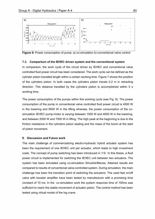
Figure 9: Power consumption of pump: a) co-simulation b) conventional valve control
7.3. Comparison of the IEHEC driven system and the conventional system
In comparison, the work cycle of the circuit driven by IEHEC and conventional valve
controlled fluid power circuit has been considered. The work cycle can be defined as the
cylinder piston travelled length within a certain working time. Figure 7 shows the position
of the cylinders piston. In both cases the cylinders piston travels 0.2 m in retracting
direction. This distance travelled by the cylinders piston is accomplished within 5 s
working time.
The power consumption of the pumps within this working cycle (see Fig. 9). The power
consumption of the pump in conventional valve controlled fluid power circuit is 4500 W
in the lowering and 9000 W in the lifting whereas, the power consumption of the co-
simulation IEHEC pump-motor is varying between 1000 W and 4000 W in the lowering,
and between 2000 W and 7000 W in lifting. The high peak at the beginning is due to the
friction resistance in the cylinders piston sealing and the mass of the boom at the start
of piston movement.
8. Discussion and Future work
The main challenge of commercializing electro-hydraulic hybrid actuator system has
been the requirement of one IEHEC unit per actuator, which leads to high investment
costs. The concept of pump switching has been introduced in /13/. In this thesis, a fluid
power circuit is implemented for switching the IEHEC unit between two actuators. The
system has been simulated using co-simulation Simulink/Mevea. Attained results are
compared to results of conventional valve-controlled system. During simulation, the main
challenge has been the transition point of switching the actuators. The used fast on/off
valve with booster amplifier have been tested by manufacturer with a promising time
constant of 10 ms. In the co-simulation work the system response time of 100ms was
sufficient to reach the stable movement of actuator piston. The control method has been
tested using virtual model of the log crane.
Group A - Digital Hydraulics | Paper A-4 83

The oscillations in the system is apparent to the fluid power circuit in which the fast on/off
valves are used for guiding the volume flow. The fast opening and closing of the on/off
valve causes pressure drops in the system which further increases the oscillations in the
system. The other reason for the oscillation is due to lacking of damping in the system.
In modelling of the studied fluid power circuit the viscous damping in the cylinders has
been the only damping considered in the system. Thus, the PI controller with cylinder
velocities feedback have been added in the modelling of the electrical machine control.
The designed fluid power circuit using IEHEC can operate with less power than the
conventional valve controlled circuit even though, there is frequent opening and closing
of switching valves of the actuators. The IEHEC driven fluid power circuit is 20 % more
efficient than conventional valve controlled fluid power circuit.
9. References /1/ Ponomarev, P., Polikarpova, M., Heinikainen, O., & Pyrhonen, J. 2011. Design
of integrated electro-hydraulic power unit for hybrid mobile working machines.
In Proceedings of the 2011 14th European Conference on Power Electronics
and Applications.
/2/ Callaghan, L., & Lynch, S. 2005. Analysis of electric drive technologies for
transit applications: Battery-electric, hybrid-electric, and fuel cells (No. FTA-MA-
26-7100-05.1).
/3/ Sgro, S. Inderelst, M., Murrenhoff, H. 2010. “Energy Efficient Mobile Working
Machines”, 7th International Fluid Power Conference Aachen, Germany.
/4/ Williamson, C., Ivantysynova, M. 2010. “Power Optimization for Multi-Actuator
Pump Controlled Systems”, 7th International Fluid Power Conference Aachen,
Germany.
/5/ Finzel D., Jang D. and Helduser U. 2010. Electro-hydraulic Dual-circuit System
to Improve the Energy Efficiency of Mobile Machines, in 7th International Fluid
PowerConference, Aachen, Germany.
/6/ Liu S. and Yao B. 2002. Energy-saving Control of Singlerod Hydraulic Cylinders
with Programmable Valves and Improved Working Mode Selection, SAE
Transactions - Journal of Commercial Vehicle, pp. 51-61.
84 10th International Fluid Power Conference | Dresden 2016
/7/ Andersson B. and Martin A. 1996. New Technologies Applied to
Electrohydraulic Controls, in International Off-highway & Powerplant Congress
& Exposition.
/8/ Lumkes J. H. and Andruch J. 2011. Hydraulic Circuit for Reconfigurable and
Efficient Fluid Power Systems, in The Twelfth Scandinavian International
Conference on Fluid Power, Tampere, Finaland.
/9/ Åman, R., Handroos, H., Ponomarev, P., Pyrhönen, J. 2012. ‘Electro-hydraulic
hybrid actuator system using integrated power unit’. Eighth Int. Fluid Power
Conf., Dresden University of Technology, Germany.
/10/ Ponomarev, P., Åman, R., Handroos, H., Immonen, P., Pyrhönen, J., & Laurila,
L. 2014. High power density integrated electro-hydraulic energy converter for
heavy hybrid off-highway working vehicles. IET Electrical Systems in
Transportation, 4(4), 114-121.
/11/ Luostarinen, L., Åman, R., Handroos, H. 2014. Development of Control
Interface for HIL Simulation of Electro-Hydraulic Energy Converter, International
Review on Modelling and Simulations (IREMOS), 7(4), pp. 653-660.
/12/ Åman, R., Ponomarev, P., Luostarinen, L.O., Handroos, H., Pyrhönen, J.,
Laurila. L. 2014. ‘Experimental Analysis on of Electro-Hydraulic Hybrid actuator
System in Off-Highway Working Vehicles’. In: ASME FPNI Ph.D Symposium on
Fluid Power. Lappeenranta, Finland, June 11-13, 2014.
/13/ Busquets, E., & Ivantysynova, M. 2014. The World’s First Displacement-
Controlled Excavator Prototype with Pump Switching-A Study of the
Architecture and Control. In Proceedings of the 9th JFPS International
Symposium on Fluid Power, Matsue (pp. 324-331).
/14/ Rahmfeld, R. 2002. Development and Control of Energy Saving Hydraulic Servo
Drives for Mobile Systems. PhD thesis. Technical University of Hamburg-
Harburg.
/15/ Ivantysynova, M. 1998. Energy saving hydraulic actuators for mobile machines.
1st Bratislavan Fluid Power Symposium, Bratislava, Slovak Republic.
/16/ Merritt, H. 1967. “Hydraulic Control Systems”, John Wiley & Sons.
Group A - Digital Hydraulics | Paper A-4 85

/17/ ABB ACS800 Technical manual [Accessed 14 Oct 2015]. Available at
https://library.e.abb.com/public/0cb03a89ae71bba5c1257b97004fdb01/EN_%
20ACS800_01_HW_K_A4.pdf
/18/ Åman, R., Handroos, H., Ponomarev, P., Pyrhönen, J. 2013. ‘Utilization of
Electro-hydraulic hybrid actuator system in off-Highway Working Vehicles’.
Eighth Int. Conf of Fluid Power Transmission and Control. Hangzhou, China,
April 9-11, 2013.
/19/ Boschrexroth. 2015a. 2/2 directional poppet valve, direct operated with solenoid
actuation.[Accessed 19 Oct.2015]. Available at: http://apps.boschrexroth.com
/products/compact-hydraulics/cv-catalog/pdf/18136-23.pdf
/20/ Boschrexroth. 2015b. Booster amplifier. [Accessed 20 Oct. 2015]. Available at:
https://brmv2.kittelberger.net/modules/BRMV2PDFDownload- internet.dll
/re30260_2012-04.pdf?db=brmv2&lvid=1163141&mvid =11743&clid =20&sid=
A4F064BB05BA 64336328D6C63E2B4E4A.borex-tc&sch =M&id= 11743,20,
1163141
/21/ Boschrexroth, 2015g. 4/3 solenoid directional control valve. [Accessed 3 Nov.
2015]. Available at: https://www.boschrexroth.com/ics/content/UpToDate/PDF/
re29026_2008-07.pdf
/22/ Handroos, H. 2010. "Methods for Combining A Theoretical and Empirical
Approach in Modelling Pressure and Flow Control Valves for CAE-programs for
Fluid Power Circuits." Lappeenranta, Finland.
/23/ Mevea. 2015. Mevea Dump Truck Simulator | Mevea Ltd. [Accessed 23 Nov.
2015]. Available at: http://www.mevea.com/products/training-simulators/
construction-simulators/meveadumptrucksimulator
86 10th International Fluid Power Conference | Dresden 2016

10. Nomenclature
x
A
d
ρ
g
Piston position [m]
Piston velocity [m/s]
Area [m2]
Diameter [mm]
Density [kg/m3]
Gravity [m/s2]
P
P
Be
ω
Uin
T
Vp
L
b
H
Pressure [Pa]
Power [W]
Effective bulk modulus [Pa]
Time constant [s]
Angular speed [rad/s]
Reference signal [V]
Simulation time [s]
Radian volume [m3/rad]
Efficiency [%]
Cylinder stroke [m]
Viscous friction coefficient [Ns/m]
Integrated time step [s]
Group A - Digital Hydraulics | Paper A-4 87

88 10th International Fluid Power Conference | Dresden 2016