Embed Size (px)
Citation preview

FOREWORD
This manual describes the explanation and service procedures concerning themodified portions of the Toyota Battery Forklifts 7FBEU15, 18, 20. For the portionsnot described herein, please refer to the New Model Features and Repair Manualsshown below.
This repair manual contains the information on the vehicles manufactured as ofOctober 2005. Please understand that the description herein may not be applicableto the vehicles produced thereafter. Any change or modifications thereafter will beinformed by Toyota Industrial Vehicles’ Parts & Service News.
The performance values described herein are for standard vehicles under ourspecified test conditions. Since the conditions (weather, road surface, maintenanceand operation) are different in actual use, the values will vary accordingly.
<Reference>New Model Features and Repair Manuals related to this manual are as follows:
NEW MODEL FEATURES7FBEU15, 18, 20 (Pub. No. PU315)
REPAIR MANUAL7FBEU15, 18, 20 (Pub. No. CU330) Vol. 17FBEU15, 18, 20 (Pub. No. CU331) Vol. 2


Service Information Bulletins affecting Models (30-)7FBCU15-32, 7FBEU15-20, 7BNCU15-25 and 8FBCU20-32
Service Information Bulletin1 SIB MA06-001 - 7FBCU Option Menu Changes2 SIB CC06-001 - A5 Error Code Additional Information3 SIB RA06-002 - Tie Rod Change4 SIB FA06-003 - Front Axle Hub Change5 SIB FA06-002 - Changes to Reamer Bolt Torque6 SIB RA04-001 - New Tie Rod End Design7 SIB MA05-009 7FBEU Option Set Menu Changes8 SIB MA05-008 Repair Manual Correction (Front Axle Bearing Preload Specification)9 SIB CE02-002R - 7FBCU 36 to 48 Volt Conversion10 SIB CY04-001 - New V & FSV Lift Cyl. Sealsfor 1~3 Ton 7 Series Trucks11 SIB BF04-003 - Battery Compartment Reinforcement Plate & Battery Stopper Adjust12 SIB DU05-004 - Reduction Gear Change13 SIB ST99-001R - Recommended Special Service Tools14 SIB ST03-001 - 7FBEU SST's for Electrical Troubleshooting15 SIB ST00-001 - 7FBCU & 7FBH SST for Troubleshooting16 SIB CC05-002 - Inching While Braking Option (7FBC(H)U15-32)17 SIB CC05-008 - TMPU Inspection Standards (7FBCU15-55)18 SIB CC05-006 - MB Contactor Cover (7FBCU15-32)19 SIB FA05-001 - Gear Case Change (7FBCU35-55)20 SIB HS05-003 Mini Lever Pressure Relief (7FBEU15-20)21 SIB MS03-001 Introduction of Optional Quad Mast for 7FBEU15~2022 SIB CE05-001 Key Switch Change (All Models)23 SIB CC05-003 Accelerator Pedal Response (Tuning 12) (7FBE(H)U15-20)24 SIB CE05-008 7FBEU Voltage Conversion25 SIB CC05-011 Low Battery Voltage / Performance Reduction26 SIB CC05-007 MB Contactor Cover (7FBEU15-20)27 SIB ST06-001 - Recommended Special Service Tools28 SIB CE05-006 Pump Motor Cooling Fan29 SIB CE05-002 Addiitonal Pump Motor Cooling Fan Kit30 SIB MA07-005 - Maintenance Indicator Changes31 SIB RA07-001 Rear Axle Flange Change32 SIB HS07-001 Addition of Back-Tilt Lock Valve33 SIB CE06-005R - Display Battery Replacement34 SIB CE06-005R Display Battery Replacement35 SIB FA07-001R Front Axle Shaft Change36 SIB CC07-004 - Tuning No. 14 Information37 SIB DM07-001 Modification of Drive Motor Rotation Sensor Bearing Section38 SIB CC08-003R Inching While Braking Option (Tuning Level 13)39 SIB DU08-001R 7BNCU Drive Unit Repair Correction40 SIB ST08-001 Recommended Special Service Tools41 SIB CE08-002R Battery Connector Bracket42 SIB HS08-002 Addition of OPSS Back-tilt Lock Valve

Service Information Bulletins affecting Models (30-)7FBCU15-32, 7FBEU15-20, 7BNCU15-25 and 8FBCU20-32
43 SIB CC08-010 7FB10-J35 Programming Changes44 SIB Option Setting and Tuning Modes (7FB Models)45 SIB BR09-001 7FB Repair Manual Corrections 46 CC09-001 7FB Revision of Repair Manual 47 CC09-003 Error Codes 31-1, 31-2 and 31-348 DU09-003 Gear Case Bolt Torque Change49 CC09-004 5F and 5G codes 50 DM09-001 Drive, Pump and Steer Motor through Bolt Torque51 DM09-002 Pump Motor Cable Clearance52 CC10-001 Flashware v4.2 53 HS10-001 7FBEU Steering Circuit Hydraulic Schematics 54 SIB CE10-004 8FBC(H)U Voltage Conversion55 SIB ST10-001 Measuring Parking Brake Force on 8FBC(H)U Trucks56 SIB BR10-001 Stainless Steel Deadman Switch Mounting Screws57 SIB CC10-005 v3.1 Software Update for Auxiliary Functions58 SIB MA10-002 8FBCU Tuning Modes Explained59 SIB CE10-006 7FBEU Motor Sensor Bearing Change60 SIB CE10-007 8FBCU Height Selector Information61 SIB CE10-008 8FBCU Shock Sensor Information62 SIB MA10-003 8FBCU Auto Speed Control Information63 SIB MA10-004 8FBCU Touch Pad Information64 SIB MA10-006 AC Motor Controller Change65 SIB CE11-001 Clamp Release Interlock (Mini Lever Units)66 SIB MA11-001 Service Hint for Greasing Rear Axle Beam Pivot Pin67 SIB FA11-001 7FBEU Front Axle Repair Kits68 SIB CC11-004 8FBCU Tuning No.1 Explained69 SIB CE11-002 8FBCU Horn Wires Breaking70 SIB CE11-003 Clamp Release Interlock (Standard Lever Units)71 SIB DM11-002 7BNCU New Auxiliary Motor and Pump
Technical News Brief1 TNB - 2001-01 - Curtis Controllers, Reach Truck 24 v. Drive Motor Overheat, EZ Pedal
Option, Over Heating Diagnosis, and 7FBCU Voltage Specs2 TNB - 2004-07 - Hydraulic oil change3 TNB-2006-02 - 7FBEU 6 Bolt Rear Axle Flange4 TNB - 2006-04 - Cast Iron Body Hydraulic Pump5 TNB - 2006-05 - Plate to Prevent Chain Rollback6 TNB - 2006-10 - 7FBCU15-32 Steer Motor Operates After Auto Shutdown Activates7 TNB - 2006-12 - 7FBCU15-18 Excessive Hydraulic Return Circuit Back Pressure8 TNB - 2006-13 - Hydraulic Fluid for Cold Storage

Service Information Bulletins affecting Models (30-)7FBCU15-32, 7FBEU15-20, 7BNCU15-25 and 8FBCU20-32
9 TNB - 2006-01R - 7FBCU/7FBEU 7-Series Electric Lift Truck Erratic Display10 TNB - 2006-09 - 7-Series Electric ROM Write11 TNB-2003-07 - Allowable Variance on Mast Shimming, 7FBEU Counterweight Retention12 TNB-2006-03 - 7FBEU Counterweight Squeaking13 TNB-2003-04 - 7FBEU Steer System – Air Purging Procedure14 TNB-2008-10 7BNCU Steer Sensor Alignment Tool15 TNB-2008-16 Dual Contactor (Units with Pump Chopper)16 TNB-2009-04 7FBEU Static Strap Update
Hotline Tech Tips1 HTT-2004-11 - 7FBCU CB-1 & CB-2; 7FBEU gradeability; 7BNCU tilt speed; Side panels
7FBCU2 HTT-2004-12 - 7FBCU15-32 Power Steer Motor, Load Sensor, ST Card; 7FBEU
gradeability; 7FBCU CB1 and CB23 HTT-2005-01 - 7FBEU Motor Bearing/RPM Sensor; E3 Display on 7FBEU; Hour Meter on
7FBEU and 7FBCU4 HTT-2005-03 - CB-2 Error codes; 7FBNCU Drive Tire Compounds; 7FBCU35-55 Differential
Oil Level5 HTT-2005-05 - 7FBCU/7FBEU, Seat Switch Testing6 HTT-2005-06 - Attachment Installation on 7BPUE, and 7BNCU; 7FBEU and 7FBEHU
Thicker Floor mat; 7FBCU, 7FBEU, and 7FB/H Battery Correction Mode and Lift Interrupt Settings
7 HTT-2005-07 - 7FBCU15-32 CPU Card Installation, Computer Board Replacement8 HTT-2005-08 - 7FBCU15-32, code 64-1, 54-1, and CB1 or 29 HTT-2005-09 - 7FBEU15-20 & 7FBEHU18 units with mini-levers10 HTT-2005-10 - 7FBEU1E-20, 7FBEHU18 Wrench Icon11
HTT-2005-11 - 7FBCU & 7FBEU/HU Load Sensor, Contactor Tip Replacement, Slow Travel12 HTT-2005-12 - 7FBCU20-32: Differential Gear Noises and Gear Number Three Failures;
7FBCU15-32: A8 Error Codes that will not clear with F1 Fuse Replacement13
HTT-2006-01 - 7 Series Electric Lift Truck Erratic Display; 7FBE Drive Unit Part Numbers14 HTT-2006-02 - 7FBCU with CB-1 and CB-2 Error Codes15 HTT-2006-03 - 7FBCU15-55, E2-2 and C2-2,-316 HTT-2006-04 - 7FBCU & 7FBEU OPSS R/M, 7FBCU & 7FBEU Board Replacement17 HTT-2006-05 - 7FBCU, 7FBEU Travel Alarm18 HTT-2006-06 - 7FBCU & 7FBEU Battery Consumption19 HTT-2006-07 - 7FBEU Slow Motor Speed20 HTT-2006-08 - 7FBEU E2-1 Error Code21 HTT-2006-09 - FE-4 Error Codes, 72-4 Error Codes,7FBEU Drive Unit P/N22 HTT-2006-10 - 7FBCU15-32 A5 Error Codes23 HTT-2006-11 - 7FBCU Drive Transistors

Service Information Bulletins affecting Models (30-)7FBCU15-32, 7FBEU15-20, 7BNCU15-25 and 8FBCU20-32
24 HTT-2006-12 - 7FB 61-1 Error Codes, 7FB Load Sensor25 HTT-2007-01 - Hydraulic Oil for Cold Storage; 7FBEU Motor Bearing Seal Install26 HTT-2007-02 - 7FB String Cutters, OPSS Tilt Back Lock Valve added27 HTT-2007-03 - CU322 update; Replacing Interface Card on 7BNCU28 HTT-2007-04 - Class 1 gear case oil29 HTT-2007-05 - 7FBCU Gear Case Sealing30 HTT-2007-06 - Steer Cylinder change31 HTT-2007-07 - Jerky Creep Speed, New Hydraulic Oil32 HTT-2007-08 - Optional 12V Power Supply, DC/MD Card troubleshooting33 HTT-2007-09 - Repair Manual 32234 HTT-2007-10 - Class 1 OPSS II, Load Sensor , and P7 & P8 Current Sensors35 HTT-2007-11 - CU322 Repair manual clarification, 7FBEU 31-1, 31-2, 31-336
HTT-2007-12 - Class 1 Alarm with OPSS37 HTT-2008-01 - Class I Gear Noise38 HTT-2008-02 - Drive Unit Part Numbers, EF-1 & EF-2 Error Codes, Flashware Cable for 39 HTT-2008-03 - 7FBE Error Codes 64-2 & H9-2, 7FBCU15-55 A8, A1 & C3 Error Codes, 40 HTT-2008-04 - No Display with EZ Pedal, (30)7FBCU15-32 Complaint of Low Top Speed 41 HTT-2008-05 - 7FBCU20-32 Battery Slide out Field Installation Kit, (30)7FBCU15-55 Drive 42 HTT-2008-06 - 7FBE Front Hub Induction Hardening and Drive Axle Clattering43 HTT-2008-07 - 7FBCU15-25 Inspecting the EHPS Transistor44 HTT-2008-08 - 7FBE Internal Gear Hardened45 HTT-2008-09 - (30)7FBCU15-32 Error Code C0-(1-6)46 HTT-2008-10 - 7FBE Drive Axle Connector Rod Adjustment47 HTT-2008-11 - Using The SST Tools In Diagnosing Board Issues and UL Ratings48 HTT-2008-12 - Diagnostic Tips49 HTT-2009-01 - Slow Lowering or Incorrect Staging During Lowering50 HTT-2009-02 - C2-2 or C2-3 Error Codes and Trouble Shooting Error Codes H9-1,2,3 Or 64-
1,2,351 HTT-2009-03 - Static Strap Mounting and Lift Interrupt Settings52
HTT-2009-04 - Battery Voltage Setting On PDI, Parking Brake Warning and String Cutters53 HTT-2009-05 - Error Codes After Card Replacement54 HTT-2009-06 - Error Codes A6-1, A6-2, A6-3, A6-5 or A6-6 at Key-On55 HTT-2009-07 - Slow Travel Speed56 HTT-2009-08 - Occurrence of Error Code AO-457 HTT-2009-09 - Jerky Travel at Slow Speeds58 HTT-2009-10 - Gear Case Bolt Torque Increase59 HTT-2009-11 - A5 Error Code On 7FBE and 7FBC Forklifts With OPSS, 5F and 5G Codes
for the 7BNCU Model Forklifts60 HTT-2009-12 - 7FBCU Transistor Test Procedure & Speed Sensor Check61 HTT-2010-01 - FE-4, E2-2, E2-4 Error Codes62 HTT-2010-02 - Switch Adjust, RF Interference on AC Trucks

Service Information Bulletins affecting Models (30-)7FBCU15-32, 7FBEU15-20, 7BNCU15-25 and 8FBCU20-32
63 HTT-2010-03 - Documenting 7FBCU Brake Inspection and Adjustment During PDI, Flashware v4.2
64 HTT-2010-04 - Class I Brush Warning Option 14, 7BNCU Diode Replace Instructions65 HTT-2010-05 - Class I 7FBEU Front Axle Repair Kits66 HTT-2010-06 - Class I AC Drive Motor Over Current Limit Checks, SAS Manual Lowering
Valve67 HTT-2010-07 - 8FBCU Slow Travel or Surging Hydraulics, Setting Time/Date68 HTT-2010-08 - 8FBCU Display, Main CPU and Changing Voltage69 HTT-2010-09 - 8FBCU Measuring Parking Brake Force, 7BNCU Software v3.170 HTT-2010-10 - 8FBCU Service Information Bulletins71 HTT-2010-11 - 8FBCU Slow Attachment Speeds, Seat Switch Failures 72 HTT-2010-12 - 8FBCU Travel Alarm in Both Forward and Reverse73 HTT-2011-01 - Speed Limit Adjustment on 8FBCU74 HTT-2011-02 - Class I-VI Common Electrical Acronyms, 7FBEU Error Codes 72-1, 72-2 or
Missing Manager's Functions75 HTT-2011-03 - Class I 8FBCU Slow Lowering w/Standard Levers76 HTT-2011-04 - Class I 8FBCU H Power Mode, 7FBEU RPM Sensor Bearing Damage77 HTT-2011-05 - Class I Adding Electrical Devices, 78 HTT-2011-06 - Class I Battery Option/Type79 HTT-2011-07 - Class I 7FBCU35-55 Using SST3 On CN11280 HTT-2011-08 - Class I 8FBCU Tuning No. 1, Back to Basics Troubleshooting81 HTT-2011-09 - Class I Important SIBs82 HTT-2011-10 - Class I 8FBC(H)U Controller Software Change83 HTT-2011-11 - Class I Adding Forward Travel Alarm84 HTT-2011-12 - Class I C1-2 Error Codes, Hyd Oil Maint and Diagnosing Intermittent
Complaints85 HTT-2012-01 - Class I 8FBCU Relief Valve Structure, Using DVOM to Check Voltage Drop


NAME SECTION
SECTION INDEX
GENERAL 0OPS & IMPROVEMENTS 1BODY 2APPENDIX 3


0123456789101112131415161718
0-1
GENERALPage
PERIODIC MAINTENANCE............................... 0-2OPS SYSTEM .................................................... 0-2
GENERAL ................................................................... 0-2CHANGES FOR INSTALLATION OF
OPS FUNCTION ...................................................... 0-3SYSTEM CONFIGURATION AND
OPERATION PRINCIPLE ........................................ 0-3DISPLAY ............................................................ 0-5
GENERAL ................................................................... 0-5

0-2
PERIODIC MAINTENANCEComparison with Former Edition: Repair Manual, Pub. No. CU330, Page 0-22
Change:
INSPECTION METHODI : Inspection. Repair or Replacement if required.M : Measurement. Repair or Adjustment if required.T : Retightening C : Cleaning L : Lubrication
OPS SYSTEM
GENERALThe OPS (Operator Presence Sensing) System is equipped as the standard feature on all models. The switch installed on the seat detects the operator, and when the operator is not seated in the normal operatingposition (operator’s seat), the OPS system interrupts the traveling power and restricts load handling operation.When the controller detects the seat switch turned off, it informs OPS operation to the operator by sounding thebuzzer (pi-)* for about 0.5 seconds and the display indication. Moreover, the display indication keeps while turningoff the seat switch. When the controller detects malfunction, the display indicate the diagnosis error code.
*: The buzzer sounds only export model.
Every 6 weeks
Every 3 months
Every 6 months
Every 12 months
Every 250 hours
Every 500 hours
Every 1000 hours
Every 2000 hours
SAFETY DEVICES, ETC.
SEAT
Loosening and damage of mounting I ← ← ←
Seat belt damage and function I ← ← ←
Seat switch function I ← ← ←
OPS Function I ← ← ←
Inspection timing
Item
S P H

0-3
0123456789101112131415161718
CHANGES FOR INSTALLATION OF OPS FUNCTION1. Change in return-to-neutral function
When the key switch or seat switch is turned ON with the direction lever in the forward or reverse position or theaccelerator pedal depressed, traveling is disabled unless the direction lever and accelerator pedal are returnedto the neutral positions.
SYSTEM CONFIGURATION AND OPERATION PRINCIPLENote:When OPS operates, the power assistance of the steering wheel is lost because the pump motor is stopped.(except for Mini-Lever Opt.)
Item Operation explanation
Travel OPSWhen the controller detects the seat switch turned off for two seconds, the drive motor control is stopped. Travel OPS is released by returning the direction lever and accelerator pedal to the neutral position and turning on the seat switch.
Material handling OPS
Standard:When the controller detects the seat switch turned off for two seconds, the movement of lift down and tilt forward is stopped by controlling the lift lock valve, tilt controlling valve. The movement of tilt backward, lift up and attachment is stopped by stopping the pump motor. Material handling OPS is released by passing one second after turning on the seat switch.
Main controller
Seatswitch
DisplayKey switch
Battery
N1
Acceleratorpedal switch
Directionswitch
Oilcontrolvalve
Liftcylinder
TiltcylinderOil
tank
Oilpump
Pumpmotor
Drivemotor
Motor driver
Motor driver

0-4
(*) The buzzer sounds only export model.
SEATSTD equipped seat is the same one equipped on previous model. It has been equipped with non-suspension seatwith seat belt manufactured by Michigan seat.Compared to previous model, variety of optional seat is increased. Optional seats are shown below. (Equipped seatsvary with the specification of option.)All seats equip switches for operator presence sensing system.When replacing seat, always use a genuine TOYOTA seat.Otherwise, the OPS may fail to operate.
Item Operation explanation
Material handling OPS
Note:• Tilt backward
When the tilt lever is operated in the state of OPS operation, the mast might move by the self-weight in the state of backward tilting.
• AttachmentWhen the attachment lever is operated in the state of OPS operation, the attachment mightmove by the self-weight.
Mini lever (OPT):When the controller detects the seat switch turned off for two seconds, the movement of lift, tilt and attachment is stopped by stopping the pump motor control and controlling the proportional solenoid valve. Load handling material handling OPS is released by returning the all hydraulic control levers to the neutral position and turning on the seat switch.(In case of mini lever, it is additional to the condition of releasing material handling OPS to return the all hydraulic control levers to the neutral position. Because the mini lever is small and physical operation force is light, it is considered that the luggage etc. put on the armrest move the mini lever by mistake.)
OPS operation information
(*)
When the controller detects the seat switch turned off, it informs OPS operation to the operator by sounding the buzzer (pi-) for about 0.5 seconds and the display indication. Moreover, the display indication keeps while turning off the seat switch.
Return to neutral warning
When the accelerator pedal is operated with turning on the seat switch without returning the direction lever to the neutral position, it informs the operator that the travel OPS is not released by sounding the buzzer (pipipipi).
Abnormality warning When the controller detects malfunction, the display indicates the diagnosis error code.

0-5
0123456789101112131415161718
DISPLAY
GENERALThe multiple display is provided in two types: standard easy model and optional all-round model.
Function list (only added or modified items):Provided — :Not provided
1. Return-to-neutral warning
(1) When the operator turns the key switch on while depressing the accelerator pedal or turning the directionswitch on to start the vehicle.
(2) After sat up, the operator depresses the accelerator pedal while turning the direction switch on and sittingdown.
2. OPS indicatorOPS indicator is displayed and the buzzer sounds for half seconds when the operator leaves the seat.
Note:The buzzer sounds only export model.
Function Easy model (standard) All-round model (optional)
Status display function 1 OPS indicator
S P H


0123456789101112131415161718
1-1
OPS & IMPROVEMENTSPage
GENERAL .......................................................... 1-2MULTI-DISPLAY FUNCTIONS .......................... 1-3
MULTI-SCREEN DISPLAY......................................... 1-3DIAGNOSIS ................................................................ 1-5MASK FUNCTIONS .................................................... 1-5
TROUBLESHOOTING ....................................... 1-9

1-2
GENERAL
Main controller
Seatswitch
DisplayKey switch
Battery
N1
Acceleratorpedal switch
Directionswitch
Oilcontrolvalve
Liftcylinder
TiltcylinderOil
tank
Oilpump
Pumpmotor
Drivemotor
Motor driver
Motor driver

1-3
0123456789101112131415161718
MULTI-DISPLAY FUNCTIONS
MULTI-SCREEN DISPLAY
GENERAL
Display and ButtonsComparison with Former Edition: Repair Manual, Pub. No. CU331, Page 3-2.
Change:
(1) Parking brake ON indicator (7) Multiple display area
(2) 2-speed travel speed set indicator (8) DOWN button
(3) Diagnosis ON indicator (9) UP button
(4) Overheat warning indicator (10) Power select button
(5) Battery charge indicator (11) Hour meter selector button
(6) Power select indicator
S P H
S E P / 3 0 A M 11 : 0 0S P H
S P H
01 11 : 0 0m p h
S P H
During traveling
S P HS P H
A 1 1 A 1 2 A 1 3
hO.1 2 3 4 5
Upon error occurrence
When OPS is operated
(7) (6) (10) (11)(5)
(1) (2) (3) (4) (8) (9)
Initial screen upon key switch on
A S E Q DU I P P ES
S P H
OT Y O T A
S P H S P H

1-4
GENERAL FUNCTIONSComparison with Former Edition: Repair Manual, Pub. No. CU331, Page 3-7.
Change:: General function : Manager’s function
DISPLAY INDICATION LISTComparison with Former Edition: Repair Manual, Pub. No. CU331, Page 3-8, 9.
Add:
USA model (standard model) Export model
Status display function OPS indicator
ModelFunction
GENERAL Screen
MASK FUNCTION Screen
OPTION SET SEAT BUZZER The buzzer sound before OPS operation.*
To be set by dealer or serviceman
En
ter
pa
ssw
ord
*: The buzzer sound only export model.

1-5
0123456789101112131415161718
DIAGNOSIS
DIAGNOSIS CODE LISTComparison with Former Edition: Repair Manual, Pub. No. CU331, Page 3-26.
Add:
MASK FUNCTIONS
ANALYZER
Vehicle Abnormalities Not Stored in Diag MemoryComparison with Former Edition: Repair Manual, Pub. No. CU331, Page 3-40.
Change:
OPTION SET
OPTION SET Menu ListComparison with Former Edition: Repair Manual, Pub. No. CU331, Page 3-64.
Add:
Display code Diag memorycode Faulty Phenomenon on vehicle Detection controller
A5 A5 Seat switch Seat switch abnormality C/R
Warning indicators Warning method Displayed code
4
Return to neutral warning:Warning buzzer sounds when starting is attempted by turning the key switch or seat switch ON with the direction switch ON or the accelerator pedal depressed.
• BeepShort beeps No display
No. Indication DescriptionSelection
Indication Meaning indication Meaning
OPT-23 SEAT BUZZEREnable/disableThe buzzer sound only export model.
Y Enable N Disable
1-6
Operation Procedure for OPTION SET ScreenComparison with Former Edition: Repair Manual, Pub. No. CU331, Page 3-65, 66, 67.
New:
1. Input the password on the GENERAL screen (see page 3-32) to display the MASK MENU screen.
2. Press button (2) twice to display “3. OPTION SET” and press button (3) (enter) to display the OPTION SETscreen.
3. Press button (3) to display the desired option item to be set on the screen.
4. Functions of buttons on the OPTION SET screen are as follows:• Button (1): N → Y• Button (2): Y → N• Button (3): Enter (to the next item screen)
*: Press button (3) on OPT-23 OPTION SET screen to display the MASK MENU screen.
S P H
=
3 O P T I O N S E T.
=M E N U
MASK MENU screen
Press button (3)
Press
button (3)
Press button (3)
OPT-4 screen
Press button (3)
OPT-2 (H/M START) hour meter starting method:
Press button (2) while keeping button (1) pressed
for 2 seconds or more.
Button (3)
Button (1)
Button (2)
S P H
S P H
< >OD E M O M O D E
P T 1
Y / N
S P HS P H
< >OH / M S T A R T
P T 2
Y / N
S P H
S P H
< >OP / C L O C K
P T 3
Y / N
S P H

1-7
S P H
< >OD E S T I
P T 4
J / I
OPT-3 screen
S P H
< >OB L E V E L
P T 5
Y / N
S P H
< >OM P H
P T 6
Y / N
S P H
< >OC / C N T R E S
P T 7
Y / N
S P H
< >OS H O U O K UT
P T 9
Y / N
S P H
< >OB T Y P E
P T 51
1 / 2
OPT-16 screen
S P H
< >OT I L T F L I M
P T 41
Y / N
S P H
< >OK N O B C O N T
P T 31
Y / N
S P H
< >OT I L T C O N T
P T 21
Y / N
S P H
< >OP A R K I GN E RR
P T 11
Y / N
S P H
< >OS E A T O F FP
P T 01
Y / N
P H
< >OB A T T E YR
P T 8
A / B
S
Press button (3)
Press button (3)
Press button (3)
Press button (3)
Press button (3)
Press button (3)
Press button (3)
Press button (3)
Press button (3)
Press button (3)
Press button (3)
Press button (3)
Not used
Not used
Not used
Button (3)
Button (1) Button (2)
S P H
S P H
S P H
S P H
S P H
S P H S P H
S P H
S P H
S P H
S P H
S P H

1-8
OPT-15 screen
Not used
Not used
Press button (3)
Press button (3)
Press button (3)
Press button (3)
Press button (3)
Not used
ADD:
Press
button (3)
Press button (3)
Button (3)
Button (1)
Button (2)
S P H
< >O3 6 V
P T 61
Y / N
S P H
S P H
< >O2 WA Y V L V EA
P T 71
Y / N
S P H
S P H
< >O4 W A Y V A L V E
P T 81
Y / N
S P H
S P H
< >OU S A
P T 91
Y / N
S P H
S P H
< >OW H E E L I N D
P T 02
Y / N
S P H
S P H
< >OS A S
P T 2 1
Y / N
S P HS P H
< >OF I S H E M A NR
P T 22
Y / N
S P H
MASK MENU screen
Press button (3)
S P HS P H
MENU
< >OS E A T U Z Z E RB
P T 32
Y / N

1-9
TROUBLESHOOTINGDIAGNOSIS CODE LIST
OPS relation
WHEN AN ERROR CODE IS DISPLAYED
Display code Diag memory code Error mode Page
A5 A5 Seat switch abnormality 1-10
WHEN NO ERROR CODE IS DISPLAYED
Display code Vehicle condition Page
Traveling and material handling fail with OPS operation display even after sitting on the seat. 1-12
Harness change relation
WHEN AN ERROR CODE IS DISPLAYED
Display code Diag memory code Error mode Page
61-1, 2 61-1, 2 Load sensor abnormality 1-45
62-1, 2 62-1, 2 Tilt angle sensor abnormality 1-47
63-1, 2, 3 63-1, 2, 3 Tilt switch abnormality 1-14
67-1 67-1 Lifting height switch abnormality 1-49
72-1, 2, 3, 4 72-1, 2, 3, 4 Steering angle sensor abnormality 1-15
73-1, 2, 3 73-1, 2, 3 Steering knob synchronizer solenoid abnormality 1-20
A4 A4 Acceleration switch abnormality 1-22
A6-1, 3, 5 A6-1, 3, 5 Material handling switch abnormality 1-23
C4-1, 2, 3, 4 C4-1, 2, 3, 4 Accelerator potentiometer abnormality 1-25
C7 C7 Direction switch abnormality 1-27
EE-1, 2, 3 EE-1, 2, 3 Abnormal communication from multi-display 1-29
F1-1, 2 F1-1, 2 Main controller →multi-display communication abnormality 1-51
FF FF D15 overcurrent 1-30
H5-1, 2, 3, 4, 5 H5-1, 2, 3, 4, 5 Lift solenoid abnormality 1-31
H6-1, 2, 3, 4, 5 H6-1, 2, 3, 4, 5 Tilt solenoid abnormality 1-34
H7-1, 2, 3, 4, 5 H7-1, 2, 3, 4, 5 Attachment 1 solenoid abnormality 1-37
H8-1, 2, 3, 4, 5 H8-1, 2, 3, 4, 5 Attachment 2 solenoid abnormality 1-40
H9-1, 2, 3 H9-1, 2, 3 Unload valve solenoid abnormality 1-43
WHEN NO ERROR CODE IS DISPLAYED
Display code Vehicle condition Page
— No display on multi-display 1-52
— Only traveling disabled (no motor revolution) 1-53
— Constant automatic fork leveling 1-55

1-10
OPS Relation
WHEN AN ERROR CODE IS DISPLAYED
A5 Seat switch abnormality (STD)
Output when the seat switch is kept ON.
Related Portion
CPU board
CN101-5 (67, LSD)
CN101-16 (51, LS–)
CN161
Seat switch
1
2
5
12
CN22
Condition for Error Detection
Has the operator been sitting on the seat before key switch ON? NormalYES
Disconnect the seat SW harness CN22 and check the LSD.ANL.: I/O MONITOR 2 I/O 2-3LSD ON/OFF check
Seat switch abnormalityLSD: 0
NO
LSD: 1
• CPU-CN22 harness abnormality (potential 67 grounded) or• CPU board abnormality

1-11
A5 Seat switch abnormality (Mini Lever)
Output when the seat switch is kept ON.
Related Portion
CPU board
CN101-5 (67, LSD)
CN101-16 (51, LS–)
CN161
Seat switch
1
2
5
12
CN43CN42
7
8
Condition for Error Detection
Has the operator been sitting on the seat before key switch ON? NormalYES
Disconnect the seat SW harness CN43 and check the LSD.ANL.: I/O MONITOR 2 I/O 2-3LSD ON/OFF check
Seat switch abnormalityLSD: 0
NO
LSD: 1
• CPU-CN43 harness abnormality (potential 67 grounded) or• CPU board abnormality

1-12
WHEN NO ERROR CODE IS DISPLAYED
Traveling and material handling fail with OPS operation display even after sitting on the seat. (STD)
Seat switch OFF or discontinuity.
Related Portion
CPU board
CN101-5 (67, LSD)
CN101-16 (51, LS–)
CN161
Seat switch
1
2
5
12
CN22
Condition for Error Detection
Disconnect CN22, connect SST2 to CN22 and check the LSD.ANL.: I/O MONITOR 2 I/O 2-3LSD ON/OFF check
Seat switch abnormalityLSD: 1
LSD: 0
• CPU-CN22 harness abnormality (potential 67 line discontinuity) or• CPU board abnormality

1-13
Traveling and material handling fail with OPS operation display even after sitting on the seat. (Mini Lever)
Output when seat switch OFF or discontinuity.
Related Portion
CPU board
CN101-5 (67, LSD)
CN101-16 (51, LS–)
CN161
Seat switch
1
2
5
12
CN43CN42
7
8
Condition for Error Detection
Disconnect CN43, connect SST2 to CN43 and check the LSD.ANL.: I/O MONITOR 2 I/O 2-3LSD ON/OFF check
Seat switch abnormalityLSD: 1
LSD: 0
• CPU-CN43 harness abnormality (potential 67 line discontinuity) or• CPU board abnormality

1-14
WHEN AN ERROR CODE IS DISPLAYED
CPU Board
63-1, 2, 3 Tilt switch abnormality
Output when open or short circuit of the tilt switch line from the CPU board to the tilt switch is detected.63-1 Forward and backward tilt switch abnormality63-2 Forward tilt switch abnormality63-3 Backward tilt switch abnormality
Related Portion
CPUboard
CN101-23 (61, LSTF+)
CN101-16 (51, LS–)
CN161Tilt switch
17
13
CN122
11
10
CN102-8 (61, LSTF)
CN101-17 (62, LSTR+)
CN102-9 (62, LSTR)
J21
12 1 J2
CN87
1
3
4
2
Condition for Error Detection
A6-3 error is indicated
No error
The forward and backward tilt switches were turned ON at the same time in the past.(Check adjustment of each switch installation)
Disconnect battery plug.Connect battery plug again and turn key switch ON.
Check if an error is detected when the tilt lever is operated in either direction.
No error
63-1 error is indicated
Perform troubleshooting for A6-3.
• Tilt switch installation defect• Tilt switch abnormality
1 is displayed on either switch.
0 is displayed on either switch after operating the tilt lever several times.
Memory 63-1
Memory 63-2, 63-3
ANL : I/O MONITOR 3 I/O3-3Operate the tilt lever in either direction and check the switch input valve when the tilt lever is neutral position.
Check the diagnosis memory The tilt lever has been turned ON for two minutes or more in the past.

1-15
• 72-1
72-1, 2, 3, 4 Steering angle sensor abnormality
Output when open or short circuit of the sensor line from the CPU board to the steering angle sensor is detected.72-1 Steering angle sensor STS1 abnormality72-2 Steering angle sensor STS2 abnormality72-3 Steering angle sensor STSC abnormality72-4 Steering angle sensor open
Related Portion
CPUboard
CN103-10 (16, D15V)
CN101-16 (51, LS–)
CN162
Steering angle sensor
13
CN101-24 (312, STS1)
CN101-30 (313, STS2)
CN101-21 (314, STSC)
J21
CN161
9
11
8
12
CN124
1
CN120
10
11
12
1 J1
J4
CN19
1
3
4
5
2
Condition for Error Detection
72-1 error is not indicated
72-1 error is indicated
Connect battery plug and turn the key switch ON.Turn the steering wheel.
Connector connection check.
ANL : I/O MONITOR 4 I/O4-1Check the STS1 input value turning the steering wheel.
Remain 1
Remain 0
A
B

1-16
Remain 0
Change to 1
CPU board defect
No continuity
Continuity
Main harness defect
Steering angle sensor defect
Remain 1
No continuity
CPU board defect
Continuity
Change to 0
Main harness defect
Steering angle sensor defect
A B
Disconnect battery plug.Disconnect CN32.Short between CN19-3 and CN19-2 of main harness side with SST2.Connect battery plug and turn the key switch ON.
ANL : I/O MONITOR 4 I/O4-1Check the STS1 input value
Disconnect battery plug.Disconnect CN101.(SST2 is connection state.)CN101-24 (312) b Continuity checkCN101-16 (51)
Disconnect battery plug.Disconnect CN19.Connect battery plug and turn the key switch ON.
ANL : I/O MONITOR 4 I/O4-1Check the STS1 input value
Disconnect battery plug.Disconnect CN19, CN101.CN101-24 (312) b Continuity checkCN101-16 (51)

1-17
• 72-2
72-2 error is not indicated
Remain 0
Remain 1
Connector connection check
72-2 error is indicated
Remain 0
Change to 1
CPU board defect
No continuity
Continuity
Main harness defect
Steering angle sensor defect
Remain 1
No continuity
CPU board defect
Continuity
Change to 0
Main harness defect
Steering angle sensor defect
Connect battery plug and turn the key switch ON.Turn the steering wheel.
ANL : I/O MONITOR 4 I/O4-1Check the STS2 input value
Disconnect battery plug.Disconnect CN32.Short between CN19-2 and CN19-4 of main harness side with SST2.Connect battery plug and turn the key switch ON.
Disconnect battery plug.Disconnect CN101.(SST2 is connection state.)CN101-30 (313) b Continuity checkCN101-16 (51)
ANL : I/O MONITOR 4 I/O4-1Check the STS2 input value turning the steering wheel.
Disconnect battery plug.Disconnect CN19.Connect battery plug and turn the key switch ON.
ANL : I/O MONITOR 4 I/O4-1Check the STS2 input value
Disconnect battery plug.Disconnect CN19, CN101.CN101-30 (313) b Continuity checkCN101-16 (51)

1-18
• 72-3
72-3 error is not indicated
Remain 0
Remain 1
Connector connection check
72-3 error is indicated
Remain 0
Change to 1
CPU board defect
No continuity
Continuity
Main harness defect
Steering angle sensor defect
Remain 1
No continuity
CPU board defect
Continuity
Change to 0
Main harness defect
Steering angle sensor defect
ANL : I/O MONITOR 4 I/O4-1Check the STSC input value
Disconnect battery plug.Disconnect CN32.Short between CN19-2 and CN19-5 of main harness side with SST2.Connect battery plug and turn the key switch ON.
Disconnect battery plug.Disconnect CN101.(SST2 is connection state.)CN101-21 (314) b Continuity measurementCN101-16 (51)
ANL : I/O MONITOR 4 I/O4-1Check the STSC input value turning the steering wheel.
Disconnect battery plug.Disconnect CN19.Connect battery plug and turn the key switch ON.
ANL : I/O MONITOR 4 I/O4-1Check the STSC input value
Disconnect battery plug.Disconnect CN19, CN101.CN101-21 (314) b Continuity measurementCN101-16 (51)
Connect battery plug and turn the key switch ON.Turn the steering wheel to left or right for one round or more.

1-19
• 72-4
Main harness defect
Approx. 0 V
Approx. 15 V
72-4 error is not indicatedConnector connection check
72-4 error is indicated
Perform troubleshooting for 72-1 (STS1), 72-2 (STS2)
CPU board defect
Approx. 15 V
Approx. 0 V
Connect battery plug and turn the key switch ON.Turn the steering wheel.
Disconnect battery plug.Disconnect CN19.Connect battery plug.
Check voltage of power supply for steering angle sensor.CN19-1 (16) b Voltage measurementCN19-2 (51)
Disconnect battery plug.Connect CN19.Connect battery plug and turn the key switch ON.
Disconnect battery plug.Disconnect CN101, CN103.Connect battery plug.Check voltage of power supply for steering angle sensor (at controller side connector).CN103-10 (16) b Continuity checkCN101-16 (51)

1-20
• 73-1
73-1, 2, 3 Steering knob synchronizer solenoid abnormality
Output when open or short circuit of the solenoid line from the CPU board to the steering knob synchronizersolenoid is detected.73-1 Steering knob synchronizer solenoid open73-2 Steering knob synchronizer solenoid short73-3 Drive circuit MOS of steering knob synchronizer solenoid short
Related Portion
CPUboard
CN104-21 (329, SOLST+)CN161
Steering knob synchronizer solenoid
18
CN104-28 (330, SOLST–)20
CN122
4
3
CN98
1
2
Condition for Error Detection
ACTIVE TEST : ACT-2 KSOLTurn the steering knob synchronizer solenoid ON.
73-1 error is indicated.
73-1 error is not indicated.Connector connection check
Other than 9.9 ± 1 Ω (at 25°C)
CPU board defect
Main harness defect
9.9 ± 1 Ω (at 25°C)
Other than 9.9 ± 1 Ω (at 25°C)
9.9 ± 1 Ω (at 25°C)
Steering knob synchronizer solenoid defect
Disconnect battery plug.Disconnect CN98.
Disconnect battery plug.Disconnect CN104.CN104-21 (329) b Resistance measurementCN104-28 (330)
Disconnect CN98.CN98-1 (329) b Resistance measurementCN98-2 (330)

1-21
• 73-2
• 73-3
Disconnect battery plug.Disconnect CN98.Connect battery plug.
ACTIVE TEST : ACT-2 KSOLTurn the steering knob synchronizer solenoid ON.
73-2 error is indicated.
73-2 error is not indicated.Connector connection check
No continuity
Harness defectContinuity
CPU board defect
Disconnect battery plug.Disconnect CN104.CN104-21 (329) b Continuity checkCN104-28 (330)
ACTIVE TEST : ACT-2 KSOLTurn the steering knob synchronizer solenoid ON.
73-2 error is indicated.
73-1 error is indicated.Steering knob synchronizer solenoid defect
ACTIVE TEST : ACT-2 KSOLTurn the steering knob synchronizer solenoid ON.
73-3 error is indicated.
73-3 error is not indicated.Connector connection check
No continuity
Harness defectContinuity
CPU board defect
Disconnect battery plug.Disconnect CN152 and turn the key switch ON.Check continuityCN104-21 (329) to P1CN104-21 (329) to P2CN104-28 (330) to P1CN104-28 (330) to P2

1-22
A4 Acceleration switch abnormality
Output when the acceleration ON signal is detected upon battery plug ON.
Related Portion
CPUboard
CN102-1 (64, SWAC)CN162
Acceleratorpotentiometer
1
CN102-22 (51, POT–)8
CN121
10
4
CN262
1J22 J3
Condition for Error Detection
NO
YESNormal
YES
Adjust acceleration switch
Harness defect
NO
No continuity
Continuity (Less than 20 Ω)
CPU board defect
Was the accelerator pedal operated upon battery plug connection?
Disconnect battery plug and disconnect CN102.CN102-1 (64) b Continuity checkCN102-22 (51)
Disconnect CN26.
Reconnect battery plug.
Is A4 error displayed?
1-23
A6-1, 3, 5 Material handling switch abnormality
Output when the material handling switch ON signal is detected upon battery plug ON.A6-1 Lift switch abnormalityA6-3 Forward and backward tilt switch abnormalityA6-5 Attachment No. 1 switch abnormality
Related Portion
CPUboard
CN101-32 (60, LSL+)
CN161Lift switch
12
CN101-16 (51, LS–)
CN122
CN11
J21
CN102-6 (60, LSL)
CN101-11 (66, LSAT1+)
CN102-10 (63, LSAT1)
CN101-23 (61, LSTF+)
CN102-8 (61, LSTF)
CN101-17 (62, LSTR+)
CN102-9 (62, LSTR)
7
17
13
12
12
9
11
10
1 J2
1
2
CN21
1
2
CN87
1
2
3
4
AttachmentNo.1 switch
Forwardtilt switch
Backwardtilt switch
Condition for Error Detection
NO
YESNormal
YES
Adjust limit switch or switch abnormality.NO
Was the material handling lever operated upon battery plug connection?
Is A6 error displayed?
Disconnect CN11 (A6-1), CN87 (A6-3) or CN21 (A6-5), and connect battery plug.
A

1-24
OK (short circuit)
NG (open circuit)Harness defect
OK (open circuit)
Harness defectNG (short circuit)
A
Disconnect battery plug.Disconnect CN101, CN102.Continuity check• A6-1
CN101-32 (60) to CN102-6 (60)• A6-3
CN101-23 (61) to CN102-8 (61)CN101-17 (62) to CN102-9 (62)
• A6-5CN101-11 (63) to CN102-10 (63)
Continuity check• A6-1
CN102-6 (60) to CN101-16 (51)• A6-3
CN102-8 (61) to CN101-16 (51)CN102-9 (62) to CN101-16 (51)
• A6-5CN102-10 (63) to CN101-16 (51)
CPU board defect

1-25
• C4-1
C4-1, 2, 3, 4 Accelerator potentiometer abnormality
C4-1 Accelerator line (POTA) voltage is below the specified level when the acceleration switch is on.C4-2 Accelerator line (POTA) voltage exceeds the specified level when the acceleration switch is on.C4-3 Accelerator line (POTA) voltage exceeds the specified level when the acceleration switch is off.C4-4 Accelerator line (POTA) voltage is below the specified level when the acceleration switch is being
operated.
Related Portion
CPUboard
CN102-1 (64, SWAC)CN162
1
CN102-2 (52, POTA)
CN102-14 (53, POTA+)Acceleratorpotentiometer
CN102-22 (51, POT–)J22
2
5
8
CN121
10
1
7
4 J3
CN26
2
3
4
1
Condition for Error Detection
Less than 0.3V
0.3 V or moreCPU board defect
The POTA value does not change.
Potentiometer adjustment defect
The POTA value changes.
CN102-2 (52) b Voltage measurementN1
ANL : I/O MONITOR 2 I/O 2-1Check the POTA value when the accelerator switch SWAC is turned from 0 to 1.
ANL : I/O MONITOR 2 I/O 2-1Check the POTA value as the accelerator is depressed further.
Disconnect CN26, and short between POTA and POTA+ with SST8.
Error is indicated
Potentiometer defect
Error is not indicated
4.8 V or more Less than 4.8 V
CPU board defect Main harness defect

1-26
• C4-2
• C4-3
• C4-4If C4-2, 3 occurs at the same time, perform troubleshooting for C4-2, 3 first.
NO
YESAccelerator potentiometer check
Less than 4.5 V
Main harness defectCN102-2 (52) b Voltage measurementN1
Does C4-2 go out after disconnecting CN26?
CPU board defect
4.5 V or more
Less than 2.5 V
Changes to 1.
0 remainsAccelerator switch defect
2.5 V or more
CN102-2 (52) b Voltage measurementN1
ANL : I/O MONITOR 2 I/O2-1Check if the SWAC value changes from 0 to 1 as the accelerator pedal is depressed.
ANL : I/O MONITOR 2 I/O2-1Check maximum POTA value when SWAC is 0.
Does C4-3 go out after disconnecting CN26?
NO
Accelerator potentiometer checkYES
NO
CPU board defect
Main harness defect
Less than 2.5 VIs C4-3 error displayed?
CPU board defect
YES
2.5 V or more
Less than 1.4 V
1.4 V or morePotentiometer adjustment defect
ANL : I/O MONITOR 2 I/O2-1Check the POTA value when the SWAC display is turned from 0 to 1 or from 1 to 0.
CPU board defect

1-27
C7 Direction switch abnormality (STD)
Output when both forward and reverse direction switches are ON.
Related Portion
CPUboard
CN101-1 (45, DSF)CN161
1
CN101-2 (46, DSR)
CN101-16 (51, LS–)
Directionswitch2
12
CN120
2
3
1J21 J1
CN9
5
4
6
Condition for Error Detection
Becomes 0.
DSF or DSR display will be 1.
Direction switch inspection
OK (Approx. 5 V)
CPU board defect
NG (Other than OK)
Disconnect battery plug and disconnect CN9.
ANL : I/O MONITOR 2 I/O2-2Check the value of DSF, DSR.
CN101-1 (45)CN101-2 (46) b Voltage measurementN1
Harness short circuit

1-28
C7 Direction switch abnormality (EZ Pedal)
Output when both forward and reverse direction switches are ON.
Related Portion
CPUboard
CN101-1 (45, DSF)CN161
1
CN101-2 (46, DSR)
CN101-16 (51, LS–)
Directionswitch2
12
CN120
2
3
1J21 J1
CN9
5
4
1
Condition for Error Detection
Becomes 0.
DSF or DSR display will be 1.
Direction switch inspection
OK (Approx. 5 V)
CPU board defect
NG (Other than OK)
Disconnect battery plug and disconnect CN9.
ANL : I/O MONITOR 2 I/O2-2Check the value of DSF, DSR.
CN101-1 (45)CN101-2 (46) b Voltage measurementN1
Harness short circuit

1-29
• EE-1
• EE-3• Reset the tuning value.• If EE-3 is displayed frequently, either the CPU board or the display may be defective.
EE-1, 2, 3 Abnormal communication from multi-display
Output upon detection of communication data abnormality from display.
Related Portion
CPUboard
CN103-13 (144, SMTDK)CN162
17
Display
CN103-14 (143, SDTMK)
CN103-15 (142, SDTMA)
CN103-16 (141, SMTDA)
CN103-10 (16, D15V)
CN103-12 (14, GNDD)
18
14
15
16
13
CN124
2
3
9
8
7
1
CN1
7
4
8
3
1
2
CN70-23
CN70-24
CN70-21
CN70-22
CN-14
CN-30
Condition for Error Detection
Disconnect CN1CN103-10 (16) b Voltage measurementCN103-12 (14)
NO
YESSee F1 error
OK (Approx. 0 Ω)
Connect the display
NG (Other than 0 Ω)
Was the battery plug connected when the display is removed?
YES
• Display defect• CPU board defect
14 V or more Less than 14 V
• Sub harness defect• Display defect
• CPU board defect• Harness defect
Is F1 error displayed?
YES
NO
Does the display turn on upon key switch ON?
NO
Disconnect battery plug and disconnect CN103 and CN70.Check the continuity.CN103-15 (142) to CN70-21 (142)CN103-14 (143) to CN70-24 (143)
• Connector connection defect• Harness defect
• EE-2

1-30
FF D15 overcurrent
Output when overcurrent of D15V power source is detected.
Related Portion
CPUboard
CN103-10 (16, D15V)CN162
13CN103-12 (14, GNDD)
Multi-display board16
J4
CN124
1
7
CN1
2
1
Condition for Error Detection
Approx. 1 kΩ or more
Display defect
Approx. 1 kΩ or less
Disconnect CN70, connect battery plug, and turn key switch ON.
CPU board defect
No error
FF error is indicated.
Disconnect battery plug, disconnect CN103, and measure the resistance between 10 pin and 12 pin of harness side.CN103-10 pin (Tester probe ) b Resistance measurementCN103-12 pin (Tester probe )
Harness defect

1-31
• H5-1
H5-1, 2, 3, 4, 5 Lift solenoid abnormality
Output when open or short circuit is detected in the lift solenoid line from CPU board to the lift solenoid (raise and/or lower).
• Error indication (reference)H5-1 Lift b1 (UP) solenoid open-circuit abnormalityH5-2 Lift b1 (UP) solenoid load short-circuit abnormalityH5-1 Lift a1 (DOWN) solenoid open-circuit abnormalityH5-2 Lift a1 (DOWN) solenoid load short-circuit abnormalityH5-5 Lift solenoid drive circuit MOS short-circuit
Related Portion
CPUboard
CN104-3 (3, SOL1+)CN163
4Lift a1 (DOWN)solenoid
CN104-5 (5, SOLa1)
CN104-4 (4, SOLb1)
CN164
10
CN163
5
CN122
12
11
CN121
5
CN75
4
8
CN74
4
8
J45
Lift b1 (UP)solenoid
Condition for Error Detection
Connect battery plug and turn key switch ON.Lift raising operation. (note that lift on the vehicle is lowered.)
H5-1 error is indicated.
0.1 A or more
Check connector connection
CPU board defect
H5-1 error is not indicated.
H5-1 error is not indicated.
Connect battery plug.Turn key switch ON.Lift raising operation.
ANL : I/O MONITOR3 I/O3-2Check lift solenoid current (during lift raising operation).
0.1 A or less
Disconnect battery plug.Replace CN74 with CN75.(Use SST 20)
Harness defect
Lift b1 (UP) solenoid defect
H5-1 error is indicated.

1-32
• H5-2
• H5-3
Disconnect battery plug.Disconnect CN104.CN104-3 (3) b Continuity checkCN104-4 (4)
H5-2 error is indicated.
Check connector connection
H5-2 error is not indicated.
Continuity
Connect battery plug.Turn key switch ON.Lift raising operation.
H5-2 error is indicated.
Connect battery plug.Turn key switch ON.Lift raising operation.
CPU board defect
Harness defect
No continuity
Disconnect battery plug.Disconnect CN74.
H5-1 error is indicated.
Lift b1 (UP) solenoid defect
Connect battery plug and turn key switch ON.Lift lowering operation. (note that lift on the vehicle is raised.)
H5-3 error is indicated.
0.1 A or more
Check connector connection
CPU board defect
H5-3 error is not indicated.
H5-3 error is not indicated.
Connect battery plug.Turn key switch ON.Lift lowering operation.
ANL : I/O MONITOR3 I/O3-2Check lift solenoid current (during lift lowering operation).
0.1 A or less
Disconnect battery plug.Replace CN74 with CN75.(Use SST 20)
Harness defect
Lift a1 (DOWN) solenoid defect
H5-3 error is indicated.

1-33
• H5-4
• H5-5
Disconnect battery plug.Disconnect CN104.CN104-3 (3) b Continuity checkCN104-5 (5)
H5-4 error is indicated.
Check connector connection
H5-4 error is not indicated.
Continuity
Connect battery plug.Turn key switch ON.Lift lowering operation.
H5-4 error is indicated.
Connect battery plug.Turn key switch ON.Lift lowering operation.
CPU board defect
Harness defect
No continuity
Disconnect battery plug.Disconnect CN75.
H5-3 error is indicated.
Lift a1 (DOWN) solenoid defect
H5-5 error is indicated.
Check connector connection
H5-5 error is not indicated.
10 V or more
Connect battery plug.Turn key switch ON.Lift raising/lowering operation.
CPU board defect
10 V or less
Disconnect battery plug.Disconnect CN104.Connect battery plug and turn key switch ON.Lift lever at neutral position.Check the voltage betweenCN104-3 (3) and CN104-23 (N2), CN104-5 (5) and CN104-23 (N2), CN104-4 (4) and CN104-23 (N2).
Harness defect

1-34
• H6-1
H6-1, 2, 3, 4, 5 Tilt solenoid abnormality
Output when open or short circuit is detected in the tilt solenoid line from CPU board to the tilt solenoid (forwardand/or backward).
• Error indication (reference)H6-1 Tilt a2 (FRONT) solenoid open-circuit abnormalityH6-2 Tilt a2 (FRONT) solenoid load short-circuit abnormalityH6-3 Tilt b2 (REAR) solenoid open-circuit abnormalityH6-4 Tilt b2 (REAR) solenoid load short-circuit abnormalityH6-5 Tilt solenoid drive circuit MOS short-circuit
Related Portion
CPUboard
CN104-6 (6, SOL2+)
Tilt a2 (FRONT)solenoidCN104-7 (7, SOLa2)
CN104-8 (8, SOLb2)11
CN163
6
7
CN75
3
7
CN74
3
7
J46
Tilt b2 (REAR)solenoid
6
CN122
10
9
Condition for Error Detection
Connect battery plug and turn key switch ON.Forward tilt operation. (note that mast is tilted backward on the vehicle.)
H6-1 error is indicated.
0.1 A or more
Check connector connection
CPU board defect
H6-1 error is not indicated.
H6-1 error is not indicated.
Connect battery plug.Turn key switch ON.Forward tilt operation.
ANL : I/O MONITOR3 I/O3-4Check tilt solenoid current (during forward tilt operation).
0.1 A or less
Disconnect battery plug.Replace CN74 with CN75.(Use SST 20)
Harness defect
Tilt a2 (FRONT) solenoid defect
H6-1 error is indicated.
1-35
• H6-2
• H6-3
Disconnect battery plug.Disconnect CN104.CN104-6 (6) b Continuity checkCN104-7 (7)
H6-2 error is indicated.
Check connector connection
H6-2 error is not indicated.
Continuity
Connect battery plug.Turn key switch ON.Forward tilt operation.
H6-2 error is indicated.
Connect battery plug.Turn key switch ON.Forward tilt operation.
CPU board defect
Harness defect
No continuity
Disconnect battery plug.Disconnect CN75.
H6-1 error is indicated.
Tilt a2 (FRONT) solenoid defect
Connect battery plug and turn key switch ON.Backward tilt operation. (note that mast is tilted forward on the vehicle.)
H6-3 error is indicated.
0.1 A or more
Check connector connection
CPU board defect
H6-3 error is not indicated.
H6-3 error is not indicated.
Connect battery plug.Turn key switch ON.Backward tilt operation.
ANL : I/O MONITOR3 I/O3-4Check tilt solenoid current (during backward tilt operation).
0.1 A or less
Disconnect battery plug.Replace CN74 with CN75.(Use SST 20)
Harness defect
Tilt b2 (REAR) solenoid defect
H6-3 error is indicated.
1-36
• H6-4
• H6-5
Disconnect battery plug.Disconnect CN104.CN104-6 (6) b Continuity checkCN104-8 (8)
H6-4 error is indicated.
Check connector connection
H6-4 error is not indicated.
Continuity
Connect battery plug.Turn key switch ON.Backward tilt operation.
H6-4 error is indicated.
Connect battery plug.Turn key switch ON.Forward tilt operation.
CPU board defect
Harness defect
No continuity
Disconnect battery plug.Disconnect CN74.
H6-3 error is indicated.
Tilt b2 (REAR) solenoid defect
H6-5 error is indicated.
Check connector connection
H6-5 error is not indicated.
10 V or more
Connect battery plug.Turn key switch ON.Forward/backward tilt operation.
CPU board defect
10 V or less
Disconnect battery plug.Disconnect CN104.Connect battery plug and turn key switch ON.Tilt lever at neutral position.Check the voltage betweenCN104-6 (6) and CN104-23 (N2), CN104-7 (7) and CN104-23 (N2), CN104-8 (8) and CN104-23 (N2).
Harness defect

1-37
• H7-1
H7-1, 2, 3, 4, 5 Attachment 1 solenoid abnormality
Output when open or short circuit is detected in the attachment 1 solenoid line from the CPU board to theattachment 1 solenoid (raise and/or lower).
• Error indication (reference)H7-1 Attachment 1 a3 solenoid open-circuit abnormalityH7-2 Attachment 1 a3 solenoid load short-circuit abnormalityH7-3 Attachment 1 b3 solenoid open-circuit abnormalityH7-4 Attachment 1 b3 solenoid load short-circuit abnormalityH7-5 Attachment 1 solenoid drive circuit MOS short-circuit
Related Portion
CPUboard
CN104-11 (9, SOL3+)
Attachment 1b3 solenoidCN104-13 (11, SOLb3)
CN104-12 (10, SOLa3)13
CN164
12
14
CN74
2
6
CN75
2
6
J47
Attachment 1a3 solenoid
7
CN122
8
11
CN121
CN122
Condition for Error Detection
Connect battery plug and turn key switch ON.Attachment 1 raising operation.(note that the attachment 1 is lowered on the vehicle.)
H7-1 error is indicated.
0.1 A or more
Check connector connection
CPU board defect
H7-1 error is not indicated.
H7-1 error is not indicated.
Connect battery plug.Turn key switch ON.Attachment 1 raising operation.
0.1 A or less
Disconnect battery plug.Replace CN74 with CN75.(Use SST 20)
Harness defect
Attachment 1 a3 solenoid defect
H7-1 error is indicated.
ANL : I/O MONITOR3 I/O3-6Check attachment 1 solenoid current (during attachment 1 raising operation).

1-38
• H7-2
• H7-3
Disconnect battery plug.Disconnect CN104.CN104-11 (9) b Continuity checkCN104-12 (10)
H7-2 error is indicated.
Check connector connection
H7-2 error is not indicated.
Continuity
Connect battery plug.Turn key switch ON.Attachment 1 raising operation.
H7-2 error is indicated.
Connect battery plug.Turn key switch ON.Attachment 1 raising operation.
CPU board defect
Harness defect
No continuity
Disconnect battery plug.Disconnect CN75.
H7-1 error is indicated.
Attachment 1 a3 solenoid defect
Connect battery plug and turn key switch ON.Attachment 1 lowering operation.(note that the attachment 1 is raised on the vehicle.)
H7-3 error is indicated.
0.1 A or more
Check connector connection
CPU board defect
H7-3 error is not indicated.
H7-3 error is not indicated.
Connect battery plug.Turn key switch ON.Attachment 1 lowering operation.
0.1 A or less
Disconnect battery plug.Replace CN74 with CN75.(Use SST 20)
Harness defect
Attachment 1 b3 solenoid defect
H7-3 error is indicated.
ANL : I/O MONITOR3 I/O3-6Check attachment 1 solenoid current (during attachment 1 lowering operation).

1-39
• H7-4
• H7-5
Disconnect battery plug.Disconnect CN104.CN104-11 (9) b Continuity checkCN104-13 (11)
H7-4 error is indicated.
Check connector connection
H7-4 error is not indicated.
Continuity
Connect battery plug.Turn key switch ON.Attachment 1 lowering operation.
H7-4 error is indicated.
Connect battery plug.Turn key switch ON.Attachment 1 lowering operation.
CPU board defect
Harness defect
No continuity
Disconnect battery plug.Disconnect CN74.
H7-3 error is indicated.
Attachment 1 b3 solenoid defect
H7-5 error is indicated.
Check connector connection
H7-5 error is not indicated.
10 V or more
Connect battery plug.Turn key switch ON.Attachment 1 raising/lowering operation.
CPU board defect
10 V or less
Disconnect battery plug.Disconnect CN104.Connect battery plug and turn key switch ON.Attachment 1 lever at neutral position.Check the voltage betweenCN104-11 (9) and CN104-23 (N2), CN104-12 (10) and CN104-23 (N2), CN104-13 (11) and CN104-23 (N2).
Harness defect

1-40
• H8-1
H8-1, 2, 3, 4, 5 Attachment 2 solenoid abnormality
Output when open or short circuit is detected in the attachment 2 solenoid line from the CPU board to theattachment 2 solenoid (forward and/or backward).
• Error indication (reference)H8-1 Attachment 2 a4 solenoid open-circuit abnormalityH8-2 Attachment 2 a4 solenoid load short-circuit abnormalityH8-3 Attachment 2 b4 solenoid open-circuit abnormalityH8-4 Attachment 2 b4 solenoid load short-circuit abnormalityH8-5 Attachment 2 solenoid drive circuit MOS short-circuit
Related Portion
CPUboard
CN104-16 (34, SOL4+)
Attachment 2a4 solenoidCN104-17 (35, SOLa4)
CN104-18 (36, SOLb4)17
CN164
15
16
CN75
1
5
CN74
1
5
J48
Attachment 2b4 solenoid
12
CN122
6
5
CN121
Condition for Error Detection
Connect battery plug and turn key switch ON.Attachment 2 forward tilt operation. (note that the attachment 2 is tilted backward on the vehicle.)
H8-1 error is indicated.
0.1 A or more
Check connector connection
CPU board defect
H8-1 error is not indicated.
H8-1 error is not indicated.
Connect battery plug.Turn key switch ON.Attachment 2 forward tilt operation.
0.1 A or less
Disconnect battery plug.Replace CN74 with CN75.(Use SST 20)
Harness defect
Attachment 2 a4 solenoid defect
H8-1 error is indicated.
ANL : I/O MONITOR3 I/O3-8Check attachment 2 solenoid current (during attachment 2 forward tilt operation).

1-41
• H8-2
• H8-3
Disconnect battery plug.Disconnect CN104.CN104-16 (34) b Continuity checkCN104-17 (35)
H8-2 error is indicated.
Check connector connection
H8-2 error is not indicated.
Continuity
Connect battery plug.Turn key switch ON.Attachment 2 forward tilt operation.
H8-2 error is indicated.
Connect battery plug.Turn key switch ON.Attachment 2 forward tilt operation.
CPU board defect
Harness defect
No continuity
Disconnect battery plug.Disconnect CN75.
H8-1 error is indicated.
Attachment 2 a4 solenoid defect
Connect battery plug and turn key switch ON.Attachment 2 backward tilt operation. (note that the attachment 2 is tilted forward on the vehicle.)
H8-3 error is indicated.
0.1 A or more
Check connector connection
CPU board defect
H8-3 error is not indicated.
H8-3 error is not indicated.
Connect battery plug.Turn key switch ON.Attachment 2 backward tilt operation.
0.1 A or less
Disconnect battery plug.Replace CN74 with CN75.(Use SST 20)
Harness defect
Attachment 2 b4 solenoid defect
H8-3 error is indicated.
ANL : I/O MONITOR3 I/O3-8Check attachment 2 solenoid current (during attachment 2 backward tilt operation).

1-42
• H8-4
• H8-5
Disconnect battery plug.Disconnect CN104.CN104-16 (34) b Continuity checkCN104-18 (36)
H8-4 error is indicated.
Check connector connection
H8-4 error is not indicated.
Continuity
Connect battery plug.Turn key switch ON.Attachment 2 backward tilt operation.
H8-4 error is indicated.
Connect battery plug.Turn key switch ON.Attachment 2 backward tilt operation.
CPU board defect
Harness defect
No continuity
Disconnect battery plug.Disconnect CN74.
H8-3 error is indicated.
Attachment 2 b4 solenoid defect
Connect battery plug.Turn key switch ON.Attachment 2 forward/backward operation.
H8-5 error is indicated.
Check connector connection
H8-5 error is not indicated.
10 V or more
CPU board defect
10 V or less
Disconnect battery plug.Disconnect CN104.Connect battery plug and turn key switch ON.Attachment 2 lever at neutral position.Check the voltage betweenCN104-16 (34) and CN104-23 (N2), CN104-17 (35) and CN104-23 (N2), CN104-18 (36) and CN104-23 (N2).
Harness defect

1-43
• H9-1
H9-1, 2, 3 Unload valve solenoid abnormality
Output when open or short circuit is detected in the unload valve solenoid line from the CPU board to the unloadvalve solenoid.
• Error indication (reference)H9-1 Unload valve solenoid open-circuit abnormalityH9-2 Unload valve solenoid load short-circuit abnormalityH9-3 Unload valve solenoid drive circuit MOS short-circuit
Related Portion
CPUboard
CN104-26 (12, SOLP+)CN164
Unload valve solenoid
18
CN104-27 (13, SOLP–)19
CN122
2
1
CN76
1
2
Condition for Error Detection
H9-1 error is indicated.
9.9 ± 1Ω (at 25°C)
Check connector connection
CPU board defect
H9-1 error is not indicated.
Other than 9.9 ± 1Ω(at 25°C)
Unload valve solenoid defect
Harness defect
ACTIVE TEST : ACT-3 PSOL Set the unload valve solenoid to ON in the ACTIVE TEST.(Connect battery plug and turn key switch ON.)
Disconnect battery plug.Disconnect CN104.CN104-26 (12) b Harness continuity checkCN104-27 (13)
Disconnect CN76.CN76-1 (12) b Solenoid resistance checkCN76-2 (13)
9.9 ± 1Ω (at 25°C)
Other than 9.9 ± 1Ω(at 25°C)

1-44
• H9-2
• H9-3
H9-2 error is indicated.
Check connector connection
Unload valve solenoid defect
H9-2 error is not indicated.
CPU board defect
Harness defect
ACTIVE TEST : ACT-3 PSOL Set the unload valve solenoid to ON in the ACTIVE TEST.(Connect battery plug and turn key switch ON.)
Disconnect battery plug.Disconnect CN104.CN104-26 (12) b Harness continuity checkCN104-27 (13)
Continuity exists
No continuity
Disconnect battery plug.Disconnect CN76.
ACTIVE TEST : ACT-3 PSOL Set the unload valve solenoid to ON in the ACTIVE TEST.(Connect battery plug and turn key switch ON.)
H9-2 error is indicated.
H9-2 error is not indicated.
H9-3 error is indicated.
Check connector connection
H9-3 error is not indicated.
CPU board defect
Harness defect
ACTIVE TEST : ACT-3 PSOL Set the unload valve solenoid to ON in the ACTIVE TEST.(Connect battery plug and turn key switch ON.)
10 V or more
10 V or less
Disconnect battery plug.Disconnect CN104.Connect battery plug and turn key switch ON.Voltage check (short circuit in the harness) betweenCN104-26 (12) and CN104-23 (N2), CN104-27 (13) and CN104-23 (N2).

1-45
• 61-1
61-1, 2 Load sensor abnormality
Output when the voltage of the load sensor is outside the specified range (open or short).61-1 Load sensor open61-2 Load sensor short
Related Portion
CPUboard
CN102-17 (58, SPL+)CN162
Load sensor
7
CN102-5 (59, SPL)
J22CN102-22 (51, POT–)
4
8
CN121
9
3
4 J3
CN90
4
3
8
CN91
1
2
3
Condition for Error Detection
Disconnect battery plug.Disconnect CN102. (SST2 is connection state.)CN102-17 (58) b Continuity checkCN102-5 (59)
61-2 error is not indicated.
No continuity
• Load sensor defect• Sub harness defect
Main harness defect
Continuity
Main harness defect
CPU board defectNo continuity
Continuity
Disconnect battery plug.Disconnect CN90.Short between CN90-3 and CN90-4 of main harness side with SST2.Connect battery plug and turn the key switch ON.
CN102-5 (59) b Continuity checkCN102-22 (51)
61-2 error is indicated.

1-46
• 61-2
61-2 error remains.
No continuity
Continuity
• Main harness defect
CPU board defect
Continuity
Disconnect battery plug, disconnect CN90, connect battery plug, and turn the key switch ON.
Disconnect battery plug.Disconnect CN102.CN102-17 (58) b Continuity checkCN102-5 (59)
Disconnect battery plug.Disconnect CN102.Short between CN90-3 and CN90-8 of main harness side with SST2.CN102-5 (59) b Continuity checkCN102-22 (51)
No continuity
• Load sensor defect• Sub harness defect
Main harness defect
Change to 61-1 error.

1-47
• 62-1
62-1, 2 Tilt angle sensor abnormality
Output when the voltage of the tilt angle sensor is outside the specified range (open or short).62-1 Tilt angle sensor open62-2 Tilt angle sensor short
Related Portion
CPUboard
CN102-16 (57, POTTA+)CN162
Tilt anglesensor
6
CN102-4 (56, POTTA)
J22CN102-22 (51, POT–)
3
8
CN121
8
2
9 J3
CN8
1
2
3
Condition for Error Detection
(SST2 is connection state.)CN102-4 (56) b Continuity checkCN102-22 (51)
Disconnect battery plug.Disconnect CN102.(SST2 is connection state.)CN102-16 (57) b Continuity checkCN102-4 (56)
62-2 error is not indicated.
No continuity
Tilt angle sensor defect
Main harness defect
Continuity
Main harness defect
CPU board defectNo continuity
Continuity
Disconnect battery plug.Disconnect CN86.Short between CN86-1 and CN86-2 of main harness side with SST2.Connect battery plug and turn key switch ON.
62-2 error is indicated.
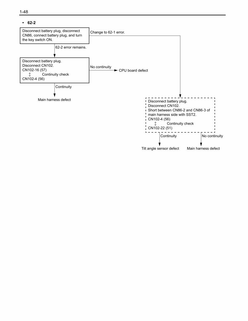
1-48
• 62-2
62-2 error remains.
No continuity
Continuity
Main harness defect
CPU board defect
Continuity
Disconnect battery plug, disconnect CN86, connect battery plug, and turn the key switch ON.
Disconnect battery plug.Disconnect CN102.CN102-16 (57) b Continuity checkCN102-4 (56)
Disconnect battery plug.Disconnect CN102.Short between CN86-2 and CN86-3 of main harness side with SST2.CN102-4 (56) b Continuity checkCN102-22 (51)
No continuity
Tilt angle sensor defect Main harness defect
Change to 62-1 error.

1-49
67-1 Lifting height switch abnormality
Output when open or short circuit of the lifting height switch line from the CPU board to the lifting height switch isdetected.
Related Portion
CPUboard
CN101-20 (91, MH2-1)CN161
Lifting height switch
16
CN101-19 (90, MH1)
J21CN101-16 (51, LS–)
15
12
CN120
6
7
1 J1
CN92
3
2
1
CN90
1
6
2
Condition for Error Detection
Other than MH: 00–
MH: 00–• Sub harness defect• Lifting height switch defect
Other than MH: 00–
Main harness defect
CPU board defectNo continuity
Continuity
ANL : I/O MONITOR 3-11Check the lifting height switch input value.
MH: 00–A
Disconnect battery plug and disconnect CN90.
ANL : I/O MONITOR 3-11Check the lifting height switch input value. (with battery plug connected)
Disconnect battery plug and disconnect CN101, and check the continuity.CN101-20 (91) to CN101-16 (51)CN101-19 (90) to CN101-16 (51)CN101-20 (91) to CN101-19 (90)

1-50
NG• Sub harness defect• Lifting height switch defect
Less than H2000
CPU board defect
Main harness defectNo continuity
Continuity
H2000 or more
A
Check the lifting height upon error indicating.
Disconnect battery plug and CN90, and check continuity.CN90-6 (90) to CN90-2 (51)
[OK] Continuity, [NG] No continuityCN90-1 (91) to CN90-2 (51)
[OK] No continuity, [NG] Continuity
OK
Disconnect battery plug and CN90, and check continuity.CN90-6 (90) to CN90-2 (51)
[OK] No continuity, [NG] ContinuityCN90-1 (91) to CN90-2 (51)
[OK] Continuity, [NG] No continuity
NG
Disconnect battery plug, disconnect CN101 and CN103, and check the continuity.• Short between CN90-6 and CN90-2
of main harness side with SST2.CN101-19 (90) b Continuity checkCN101-16 (51)
• Short between CN90-1 and CN90-2 of main harness side with SST2.CN101-20 (91) b Continuity checkCN101-16 (51)
OK

1-51
Note:Other error codes, if any, are not indicated because of no communication from the CPU board when F1-1occurs. F1-1 is kept indicated on the multi-display screen regardless of key switch ON or OFF.
F1-1, 2 Main controller →multi-display communication abnormality
Output upon detection of communication data abnormality from CPU board.
Related Portion
CPUboard
CN103-16 (141, SMTDA)CN162
Multi-display15
CN103-13 (144, SMTDK)17
CN124
8
2
CN1
3
7
CN70-22 (141, SMTDA)
CN70-23 (144, SMTDK)
Condition for Error Detection
OK
No continuity
Harness defect (Between CN103 and CN70)
Correct the defect
Continuity
NGCN103, CN124, CN70 and CN1 connection condition check
Disconnect battery plug, disconnect CN103 and CN70.CN103-16 (141) b Continuity checkCN70-22 (141)CN103-13 (144) b Continuity checkCN70-23 (144)
• CPU board defect• Multi-display defect

1-52
WHEN NO ERROR CODE IS DISPLAYED
No display on multi-display
• No power supply to multi-display• Multi-display defect
Related Portion
CPUboard
CN103-10 (16, D15V)CN162
Muli-display13
CN103-12 (14, GNDD)16
CN124
1
7
CN1
2
1
CN70-14 (16, D15V)
CN70-30 (14, GNDD)
Condition for Error Detection
OK
CPU board defect
See page 4-145. (Vehicle does not move.)
NG (1. ∞ Ω2. Approx. 0 Ω)
NG
Disconnect battery plug, disconnect CN1 and CN103.1. CN1-2 (16)
b Continuity checkCN103-10 (16)CN1-1 (14) b Continuity checkCN103-12 (14)
2. CN1-2 (16) b Short-circuit checkCN1-1 (14)
Harness defect(Between CN1 and CN103)
It is possible to perform traveling and material handling operation.
Disconnect battery plug, disconnect CN1, and connect battery plug.CN1-2 (16) b Voltage measurementCN1-1 (14)
NG (0 V)
OK (Approx. 15 V)Disconnect battery plug, connect CN1, disconnect CN70, and connect battery plug.CN70-14 (16) b Voltage measurementCN70-30 (14)
OK (Approx. 15 V)
Multi-display defect Harness defect (Between CN1 and CN70)
NG (0 V)
OK ( 1. Approx. 0 Ω2. ∞ Ω)

1-53
Only traveling disabled (no motor revolution)
Related Portion
CPUboard
CN101-1 (45, DSF)CN161
Direction switch
1
CN101-2 (46, DSR)
J1CN101-16 (51, LS–)
CN102-1 (64, SWAC)
CN102-2 (52, POTA)
CN102-14 (53, POTA+)
CN102-22 (51, POT–)
2
12
CN120
2
3
1
CN9
5
4
6
Acceleratorportentiometer
CN162
1
2
5
8
CN121
16
1
7
4 J3
CN262
3
4
1
NO
Accelerator OFF, direction switch OFF, and parking OFF (It returns.)
YES
Changes
Both have no change.
Has beep sound been output?
ANL : I/O MONITOR 2 I/O2-1SWAC and POTA value check with accelerator pedal depressing.
Both change.
ANL : I/O MONITOR 2 I/O2-2DSF and DSR value check with direction switch operation.
Voltage measures with direction switch ON and accelerator ON.P7 , P8 , P9 b Voltage measurementN1 P71 , P81 , P91 b Voltage measurementN1
OK (All approx. 24 V)
A
No change
Other than OK
Accelerator check
Direction switch check
Traveling AC driver defect

1-54
YES
Motor cable and motor checkNO
Rotates
Is there sound from the motor?
Perform troubleshooting for C8
A
Does not rotate
Brake check
Disconnect battery plug.Does front wheels rotate when jack up the vehicle to cause the front wheels to float?

1-55
Constant automatic fork leveling
Related Portion
CPUboard
CN101-18 (70, SWTK) CN161
Knob switch4
CN101-16 (51, LS–)12
CN122
2
1
CN841
2
OFF (display 0)
Tilt cylinder check
Leaned forward from leveling position
ON (display 1)
Perform matching No.1, No.2Lift down the fork and operate the tilt lever to the forward position.
Automatic fork leveling is remained ON
OFF (display 0)
ON (display 1)
Operate normally
Does not stop
ANL : I/O MONITOR 3 I/O3-9Check the valve of automatic fork leveling switch.
Tilt knob switch OFF.
ANL : I/O MONITOR 3 I/O3-9Check the valve of automatic fork leveling switch.
Use it as it is.
CN101-18 b Voltage measurementCN101-16
Approx. 5 V
• Harness defect• Switch defect
Approx. 0 V
CPU board defect
Not leaned forward from leveling position
Does pump motor stop without a turning steering wheel when direction switch is neutral position and the fork is at leveling position?
StopCPU board defect


0123456789101112131415161718
2-1
BODYPage
SEAT SWITCH ................................................... 2-2

2-2
SEAT SWITCHInspection:
Push the seat cushion to check seat switch continuity.
Measuring position : between seat switch CN22-1 and CN22-2
Standard : When not pushed : ∞ ΩWhen pushed : 0 Ω
Note:If the standard is not satisfied, replace the cushion ASSY.
CN43

0123456789101112131415161718
3-1
APPENDIXPage
SST LIST ............................................................ 3-2CONNECTOR DRAWING .................................. 3-3CONNECTING DIAGRAM................................ 3-13ELECTRIC WIRING DIAGRAM ....................... 3-14

3-2
SST LIST
Illust. Part number Part nameSection
1 2
09230-13130-71 AC controller diagnosis kit

3-3
0123456789101112131415161718
CONNECTOR DRAWING
( ):OPT( ):OPT
(41) - (AM) (41) (GR) (CN29-1)
2
1 1
2
NO
1
2
TABP C J NO
1
2
RECP C J
CN3 HORN SW.
12 1 2
J1
RECTAB
2
1
2
1
JCPNOJCPNO
BR
R
65
51 B51
CN120-4Y65
CN6
BLS
BLS
BRAKE SW.
12 1 2
NO
1
TABP C J NO
RECP C J
1
2 2 CN123-1STLS
STLS
111 R
101 Y
111 SL
101 R J9
CN5 STOP LAMP SW.
CN4
CN29-1(-)- AM(-) 41(-) GR(-)
JCP
REC
2
1
NOJCP
TAB
2
1
NO
4
41(-)
1
4
1
KEY SW.
3
8 6
4
7
1
5
2
5 6
1
7
42
8
3
CN1
8 8
6 6
5
4
7
3
5
4
2
1
2
1
JCP
REC
7
3
NOJCP
TABNO
DISPLAY
14 W14 W CN124-7CN70-30
16 R J4
141 V CN124-8
143 SL CN124-3
144 O CN124-2
142 B CN124-9
16 R CN70-14
141 V CN70-22
143 SL CN70-24
144 O CN70-23
142 B CN70-21
48 P HORN48 - HO+
41 GR J641 - HO-
33
4 43 Y CN29-2434 - IG
2
3
2
3
14
13
12
11
10
9
8
7
14 11 10
6 5
13
4
12 9
3
8
2 1
7 7
1 2
8
3
9 12
4
13
5 6
10 11 14
CN8
5
4
3
2
RECJCP
TAB
1
NO
TURN & LIGHT SW.
6
115 - LH
116 - LT
N2 - EL
108 - TR
109 - TL
110 - TB CN12-1GR110
J13G109
J14SL108
J8LN2
CN46-3LG116
CN45-3P115
6
NO
1
P C J
2
3
4
5
7
8
9
10
11
12
13
14
LIFT SW.CN11
NO P C J NO P C J
1
2
1
2
TAB REC
212 1
123456789
18 17 16 15 14 13 12 11 10 10 11 12 13 14 15 16 17 18
987654321
TAB REC
CN9
CN9
DIRECTIONAL SW.
14
13
12
11
10
9
8
7
5
4
3
2
JCP
1
NO
6 51 B J1
43 Y J5VBKY-43
LS--516
NO
1
P C J
2
3
4
5
7
8
9
10
11
12
13
14
15 15
16 16
17 17
18 18
103 P CN123-6DSBU-103
120 Y CN123-5DSFO-120
46 G CN120-3DSR-46
45 W CN120-2DSF-45
43 - VBKY 43 Y J5
60 R CN122-12
51 LG J2
60 R
51 BR
LS L
LS L
6 6
55
44
NO
3
TABP C J NO
3
RECP C J
1
2
1
2
DIRECTIONAL PEDAL
1 2 3
4 5 6
123
456
<OPT>
51 - LS-
120 - DSFO
103 - DSBU
46 - DSR
45 - DSF
43 - VBKY
51 B J1
120 Y CN123-5
103 P CN123-6
46 G CN120-3
45 W CN120-2
43 Y J5

3-4
N2 L CN14-2 J8LN2
12 1 2
NO
1
TABP C J NO
RECP C J
1
2 2
CN20 HEAD LAMP LH
44
33
JCP
2
1
NOJCP
2
1
NO
FR COMBI LHCN18
RECTAB
1 2
3 4
12
34
LF-L
LF-L
LC-L
LC-L104
N2
N2
109 -
-
-
-
FR COMBI LHCN17
2
1
2
1
JCP
REC
3
NOJCP
TAB
3
NO
5 43 2 1 1 2 3
4 5
4 4
5 5
66
66
-
-
-
-108
N2
N2
104 LC-R
LC-R
LF-R
LF-R
4 3
2 1
43
21
TAB REC
CN14 FR COMBI RH
NO
1
2
P C J NO
1
2
P C J
3 3
4 4
HEAD LAMP RHCN16
22
1
JCP
RECNOJCP
TAB
1
NO
212 1
1
2 2
1
CN12
110
43
-
-
FRY
FRY
110
43
GR
Y
CN8-14
J522
1
JCP
RECNOJCP
TAB
1
NO
FLASHER RILAY
6 5 4 3
2 1
6543
21
CN19
55
44
2
1
2
1
JCP
REC
6
3
NOJCP
TAB
6
3
NO
STEERING SENSOR
NO
2
1
TABP C J NO
2
1
RECP C J
PBLS
PB
2 1 21
CN15
-
-
LS
PARKING SW.
6 6
6 6
55
44
54321123
45
NO
3
TABP C J NO
3
RECP C J
1
2
1
2
CN13 FR COMBI RH
N2 L J8
104 O J10
102 G J11
108 SL J14
101 Y J9
N2 W J51
104 G CN14-4
102 Y CN16-1
108 G-Y CN14-1
101 R CN96-7
108 G-Y CN13-4
N2 L CN13-5
N2 W J51
104 G CN13-2
51
66
51 B J1
66 R CN120-8
LH-R102 -
LH-RN2 -
CN13-3102 Y
J51N2 W
N2 L J8
J10O104
102 G J11
J13
J8L
G109
N2
N2 J51W
CN18-4G104
102 Y CN20-1
CN18-1G-Y109
N2 L CN18-2
109 G-Y CN17-4
N2 CN17-5
N2 J51
104 G CN17-2
W
L
16 R J4
51 B J1
312 Y CN120-10
313 V CN120-11
314 L CN120-12
16 - IG
51 - ESS
312 - SS1
313 - SS2
314 - SSC
102 - LH-L
N2 - LH-L
102 Y CN17-3
N2 W J51
SMART ALARM
-N2
-103
BZ
BZ
CN23-2
WN2
O103 J56
J5422
2
1
2
1
1
JCP
RECNOJCP
TAB
1
NO
SEAT SW.CN22
NO P C J NO P C J
1
2
1
2
TAB REC
212 1
ATT SW.CN21
NO P C J NO P C J
1
2
1
2
TAB REC
212 1
NO
1
TABP C J NO
RECP C J
1
1
2
1
2
2 2
198
N2
CN23
CHI
CHI
198
N2
BACK CHIME
63 R
BR51
63 V CN122-9
J2LG51
ATT
ATTLS
LS
DLS-67
51 - DLS
67 L CN161-5
51 B J21
-
-
GR J12
L J31

3-5
0123456789101112131415161718
123456 654
321
TAB
CN29 KEY SW.
REC
2 1 21
NO P C J NO P C J
2 2
1 1
GND
OUT
W
Y317
51-
-317
51
CN32
NO
1
2
TABP C J NO
1
2
RECP C J
1 2 3123
3 316 - VCC 3 316 SL
TIRE ANGLE SENSOR
3 3
NO
3
6
TABP C J NO
3
6
RECP C J
1
2
1
2
4 4
5 5
CN34
J56
R
R
R
R
R
103
108
103
111
104
N2
TRN108 BR CN38-5
O
SL J53
G J55
B/U
STP
TL
103
111
104
EN2 W J54
1 2
4
5 656
12
4
RR COMBI RH
3 34
2 1
4
21
104
111
109
TL
STP
TRN
N2 E
109
104
111
N2
L
L
L
L
CN31
44
2
1
2
1
JCP
REC
3
NOJCP
TAB
3
NO
RR COMBI LH
NO
3
4
TABP C J NO
3
4
RECP C J
1
2
1
2
1 2 3 41234
VC
VTA
IDL
E2
52
64
51
53-
-
-
-
52
64
51
53
CN26 ACCEL
FORWARD CHIMECN24
N2
120
22
2
1
2
1
1
JCP
RECNOJCP
TAB
1
NO
W J3
SL CN121-10
GR CN121-1
O CN121-7
41 GR CN4-1
43 Y CN4-2
41 GR J6
43 Y J5
F6-4 44 J30BR444
3 3
F4,F5,F6 FUSE
P2
NO
1
2
TABP C J NO
1
2
RECP C J
PP2F6- CN136-6
CN27
J29- F5 41 GR
6
5
6
5 41
L
Y CN123-5
J31
P1 W CN136-4- F5P1
P1 B CN136-3- F4P1
101 Y CN123-4101 - F4
J55G
J53SL
CN38-6G-Y
J54W
J22
CN163-13
CN163-14
LW
LW-
-N2
107 CN38-7V107
J54WN2
12 1 2
NO
1
TABP C J NO
RECP C J
1
2 2
CN36 RR WORKING LAMP
11
8 8 N2N2
7 7 107107
6 6 109109
5 5 108108
8 7 6 5 4
3 2
87654
32
NO
3
4
TABP C J NO
3
4
RECP C J
1
2
1
2
CN38
104
198
111
104
198
111
RR UPR
4343 L FB
SL J53
O J56
G J55
BR CN34-5
G-Y CN31-3
V CN36-1
W J54
Y J39
R CN123-1
GR CN165-5
O CN123-3
SL CN123-7
G CN123-8
B CN123-2
L J31
20
21
28
22
23
29
24
25
30
5151
30
25
24
29
23
22
28
21
20
MINI LEVER
51010
5
10 10
9 9
CN41
NO P C J NO P C J
1
2
1
2
TAB REC
876321
8 7 63 2 14
949
3
4
5
6
7
8
3
4
5
6
7
8
R CN161-19
B CN164-2
G CN164-6
O CN161-17
LG CN161-13
Y CN164-7
V CN161-7
L CN164-3
GR CN164-8
W CN164-1
<OPT>
R
B
G
O
LG
Y
V
L
GR
W J49
CN79-1
CN79-3
CN79-2
CN78-1
CN78-3
CN78-2
CN77-1
CN77-3
CN77-2

3-6
12 1 2
51
67
70
31
27
26
MINI LEVER
26
27
31
70
67
518
7
6
5
4
3
8
7
6
5
4
3
84
84 123
5671 2 35 6 7
RECTAB
2
1
2
1
JCPNOJCPNO
CN42
V CN164-4
SL CN164-5
LG CN164-9
BR CN161-14
L CN161-5
B J21
<OPT>
<OPT>
B CN42-8
L CN42-7
SEAT SW
NO
1
2
TABP C J NO
1
2
RECP C J
CN43
67
51 -
- 67
51SOL P
SOL P
V CN80-2
SL CN80-3
LG CN80-1
BR CN85-2
L CN43-1
B CN43-2
CN46
RECTAB
4
1
4
1
TAIL LAMP RELAY
2
3
2
3
-4 4
-3 3
3
2
3
2
HEAD LAMP RELAY
1
4
1
-
4
NO
1
2
TABP C J NO
1
2
RECP C J
-
CN45
CN110-12
J27
CN110-11
CN110-9
SL
P
BR
O
77
78
76
75
77
78
76
75
DM SPEED LH
4 L SSD12 4
3 B SSD1- 3
SSD1+
SSD11
R
W
NO
1
2
TABP C J NO
1
2
RECP C
CN59
J
43
211 2
3 4
CN110-13
J27
W
P
87
78
87
78
DM TEMP LH
NO
1
2
TABP C J NO
1
2
RECP C J
2 1 21
TD1-
TD1+
B
R
CN58
CN111-12
J26
CN111-11
CN111-9
R
P
W
LG83
84
86
85SSP2
SSP-
SSP1
SSP+
85
86
84
83
PM SPEED
4 L 4
3 B 3
R
W
NO
1
2
TABP C J NO
1
2
RECP C
CN56
J
43
211 2
3 4
CN109-12
J28
CN109-11
CN109-9
SL
P
BR
O
43
21 1 2
3 4
J
CN53
81
82
CP
REC
2
1
NOJCP
TAB
2
1
NO
W
R
81
82
SSD21
SSD2+
80
3SSD2-B
80
3
79
4SSD22L
79
4
DM SPEED RH
CN111-13
J26
BR
P
CN55
89
86
JCP
REC
2
1
NOJCP
TAB
2
1
NO
89
86
1 212
B
R
TP-
TP+
PM TEMP
101 Y J9
101 Y J9
115 P CN8-8
102 G J11
101
101
115
102
COIL+
SW+
COIL-
SW-
SW-
COIL-
SW+
COIL+
104
116
101
101
J10O104
CN8-9LG116
J9Y101
J9Y101-
JCP
2
1
NOJCP
2
1
NO
-
33 -
44 -
CN109-13
J28
CN52
88
82
R
B
88
82
TD2+
TD2-
1 212
JCP
REC
2
1
NOJCP
TAB
2
1
NO
DM TEMP RH
R
P
12 21
FAN(EX)
B
BR
J23
J30
39
44
FAN EX (-)B39
R44 FAN EX (+)
CN50
22
1
JCP
RECNOJCP
TAB
1
NO

3-7
SOL P
SOL P 13
12-
-13
12
CN76
JCP
REC
2
1
NOJCP
TAB
2
1
NO
12 21
C/V PRESSURE SOL.
W
G
B
R
CN41-3
CN41-2
CN41-1
J49
28
21
20
51
VC
VTA2
VTA1
E2
28
21
20
51
LIFT LEVER
NO
3
4
TABP C J NO
3
4
RECP C J
1
2
1
2
1 2 3 41234
-
-
-
-
CN77
CN122-2BR
CN122-1LG
<OPT>
<OPT>
W
LG
SL
V
ATT2 LEVER
31
27
26
51 E2
VTA1
VTA2
VC 31
27
51
26
CN42-3
CN42-2
CN42-1
J49
CN80
-
-
-
-
4 3 2 1 4321
2
1
2
1
JCP
REC
4
3
NOJCP
TAB
4
3
NO
W
V
L
GR
J49
30
25
24
51
ATT1 LEVER
51
24
25
30 VC
VTA2
VTA1
E2
CN41-9
CN41-8
CN41-7
NO
3
4
TABP C J NO
3
4
RECP C J
1
2
1
2
1 2 3 41234
-
-
-
-
CN79
Y
LG
O
W
TILT LEVER
51
22
23
29 VC
VTA2
VTA1
E2 51
22
23
29 CN41-6
CN41-5
CN41-4
J49
CN78
-
-
-
-
4 3 2 1 4321
2
1
2
1
JCP
REC
4
3
NOJCP
TAB
4
3
NO
<OPT>
<OPT>
<OPT>
16 16
17 17
18 18
6 6
22
33
6
161718
23
181716
632
-
-
-
-
-
-
-
-
-
-
-
-
-
-
-
-
-
-
-
-
-
-
-
127
126
9 125
8 124
180
138
137
7
4
5
18212
13 181
16
N2
139
140
142
141
144
143
123
122
121
183
184
11
10
14
15
19
20
21
22
23
24
25
26
27
28
29
30 14
1 43 -
2829
13 12 7
30 27 26 25 24 23 22 21 20 19 15
14 11 10 9 8 5 4 1
TAB
REC
30
29
28
27
26
25
24
23
22
21
20
19
15
14
10
11
GNDD 14 W CN1-1
AVD4
AVD3
CHG SW1
CHG SW2
CHG SW3
SL143 CN1-4SDTMK
144SMTDK CN1-7O
SMTDA 141 V CN1-3
SDTMA 142 B CN1-8
SLL
STT
N1
D15V CN1-2R16
AVD1 13
12AVD2
1 4 5 8 9 10 11 14
15 19 20 21 22 23 24 25 26 27 30
7 12 13
2928
NO
TABP C J NO
5
RECP C J
1
4
7
CN70
SL/L+
48V
SL/L-
AVD(+)
8CHG LED1
9CHG LED2
CHG LED3
CHG LED4
DISPLAY
-
-
-
-
-
-
-
-
C/V SOL.(UPR)
4
8
11
36
3
6
9
4
8
11
36
3
6
9
34 34
SOL Lb1 (-)
SOL Tb2 (-)
SOL ATb3 (-)
SOL ATb4 (-)
SOL Lb1 (+)
SOL Ta2 (+)
SOL ATa3 (+)
SOL ATa4 (+)
CN74
NO P C J NO P C J
1
2
1
2
TAB REC
765321
7 6 53 2 14
848
3
4
5
6
7
8
3
4
5
6
7
8
-
-
-
-
-
-
-
-
C/V SOL.(LWR)
3
5
7
10
35
6
9
34
5
7
10
35
3
6
9
34
SOL La1 (-)
SOL Ta2 (-)
SOL ATa3 (-)
SOL ATa4 (-)
SOL Lb1 (+)
SOL Ta2 (+)
SOL ATa3 (+)
SOL ATa4 (+)
CN75
NO P C J NO P C J
1
2
1
2
TAB REC
765321
7 6 53 2 14
848
3
4
5
6
7
8
3
4
5
6
7
8
G J48
L J47
LG J46
R J45
W CN121-12
GR CN121-11
P CN121-6
B CN121-5
G J48
L J47
LG J46
R J45
P CN122-5
BR CN122-7
V CN122-9
O CN122-11
<OPT>
<OPT>
SOLD(-)
SOLD(+) BR701-701
22
JCPNOJCPNO
-51 B51
1 212
REC
TILT KNOB SW.CN84
TAB
CN122-2
J1
BR
W
TILT KNOB SW.
CN42-5
J49
70
51
-
- SWTK(-)51
SWTK(+)70
TAB RECJCP
2
1
NOJCP
2
1
NO
CN85
1 22 1
<OPT>

3-8
1-1
22
JCPNOJCPNO
-
REC
TILT SOL.CN89
TAB
TAB
CN88 LIFT SOL.
REC
2 1 21
-
NO P C J NO P C J
2 2
1 - 1
TILT SW.CN87
4
3
4
2
1
2
1
JCP
REC
3
NOJCP
TABNO
2
43
112
34JCP
REC
2
1
NOJCP
TAB
2
1
NO
CN98
SOL ST-
- SOL ST
1 212
STEERING SOL.
3 2 1 321
SWMH1-902CN90-6O902
JCP
REC
3
1
NOJCP
TAB
3
1
NO
SWMH1CN90-2
CN90-1
-
-91
51R
B91
51
CN92
SWMH1
HEIGHT SW.
CN91-1BR
8 8 51CN91-351 R
7 7
6 6 90CN92-290 O
5 5
NO
3
4
P C J NO
3
4
P C J
1
2
1
2
58
59
51
58
CN91-259 Y
CN92-151 R
91CN92-3B91
8 7 6 54 3 2 1
8765
4321
CN90
RECTAB
MAST HARNESS
321123
CN86
57
51 -
- 57
51VRAT
VRAT
NO
1
3
TABP C J NO
1
3
RECP C J
2 56 - VRAT 2 56
TILT SENSOR
CN90-3Y592SPL-592
JCP
REC
3
1
NOJCP
TAB
3
1
NO
CN90-4SPL
SPL
BR
R51
58-
-51
58
CN91
CN90-8
PRESSURE SENSOR
61 - LSTF 61 O CN122-11
51 LG J2
62 LG CN122-10
51 LG J2
51 - LS-
62 - LSTR
51 - LS-
CN121-9
J3W
CN120-7
CN121-3Y
J1B
CN120-6GR
BR
O
329 B CN122-4
330 GR CN122-3
329
330
L CN121-8
G CN121-2
W J3
1 212
SOL L +
SOL L -
SOL T +
SOL T -
3 P CN163-4
4 LG CN163-5
6 G CN163-6
7 B CN163-7
3
4
6
7
1
32
23
1
<OPT>
7
1 1
7
CMP LAMP SWCN96
LCMP
JCP
RECTAB
JCPNO NO
STPOT--117 SL117
2
1
2
1
3 3
4 4
5 5
6 6
7 101 - SPL 7 101 R CN13-6
8 8
DRIVE CONT.RH
RECTAB
1 2 4 5 67 8 9 10 11 12 13
1245678910111213
3 3
CN109
CN110
33
-
-
-
-
-
-
-
-
-
-
-
-
-
13
13 12 11 10 9 8 76 5 4 2 1
1312111098765421
TABP C J
3
7
REC
1
2
4
5
6
9
8
12
11
10
NO
145
146
147
42
75
78
76
77
87 TD1+
SSD12
SSD11
SSD1-,TD1-
SSD1+
CUDON
KEYSTART
CANGND
CANTRD
CANL
CANH
CUDID1
CUDID0
DRIVE CONT.LH
J66
J65
J64
W
SL
BR
P
O
G
L
V
B
CN58-2
CN59-4
CN59-2
J27
CN59-1
J25
87
77
76
78
75
42
147
146
145
12
11
10
8
9
6
5
4
7
3
2
1
JCPNO
13
13
NO P C J
1
2
3
7
4
5
6
9
8
10
11
12
145
146
147
42
79
82
80
81
88
J25
CN53-1
J28
CN53-2
CN53-4
CN52-2
B
V
L
G
O
P
BR
SL
R
J64
J65
J66
82 CUDID0
CUDID1
CANH
CANL
CANTRD
CANGND
KEYSTART
CUDON
SSD2+
SSD2-,TD2-
SSD21
SSD22
TD2+88
81
80
82
79
42
147
146
145
NO
10
11
12
8
9
6
5
4
2
1
7
3
JCP
13
-
-
-
-
-
-
-
-
-
-
-
-
-
82 P J28

3-9
NO
10
11
12
CN111
8
9
6
5
4
2
1
REC
7
3
JCP
TAB
1 2 4 5 67 8 9 10 11 12 13
1245678910111213
13
-
-
-
-
-
-
-
-
-
-
-
-
-
3 3
KEYSTART
SSP+
SSP-,TP-
SSP1
SSP2
TP+
CANTRD
CANL
CANH
CUPID1
CUPID0
CANGND
CUPON
86
145
146
147
42
83
86
84
85
89
PUMP CONT.
BR
R
W
P
LG
G
L
V
B
P
CN55-2
CN56-4
CN56-2
J26
CN56-1
J26
J66
J65
J64
J25
89
85
84
86
83
42
147
146
145
86
13
NO P C J
1
2
3
7
4
5
6
9
8
10
11
12
85 6 7
4321
11109 12
CN122
12 91011
1234
7 6 58
1212
1111
NO P C J NO
3
7
P C J
1
2
1
2
4
5
3
7
4
5
66
9 9
88
10 10
J21(CN164-19)51(13) LG J2(CN76-2)
70(12) BR CN84-1(CN76-1)
330 GR CN98-2
329 B CN98-1
(35) (P) (CN75-5)
(34) (G) (J48)
(10) (BR) (CN75-6)
(9)
63(7) V CN21-1(CN75-7)
62(6) LG CN87-3(J46)
61(5) O CN87-1(CN75-8)
60(3) R CN11-1(J45)
CN161-14(CN164-18)
CN161-20
CN161-18
(CN164-16)
(CN164-15)
(CN164-13)
(CN164-12)
CN161-7(CN163-7)
CN161-13(CN163-6)
CN161-17(CN164-10)
CN161-19(CN163-4)
51(13) LG
70(12) BR
330 GR
329 B
(35) (P)
(34) (G)
(10) (BR)
(9) (L)
63(7) V
62(6) LG
61(5) O
60(3) R
(L) (J47)
JOINT
TAB REC ( ):OPT( ):OPT
O
W
Y
71
REC
1098 112 3 4 5 6
JC
G CN86-2
CN90-3
J3
CN26-4
GR CN26-3
L CN86-1
BR CN90-4
SL CN26-2CN162-1
CN162-7
CN162-6
CN162-2
CN162-5
J22
CN162-4
CN162-3
J
10
8
9
6
5
4
7
3
2
1
PNO
11
12
JOINT
56
59
51
53
52
57
58
64
TAB
10
8
9
6
5
4
2
1
7
3
CPNO
11
12
56 G
59 Y
51 W
53 O
52 GR
57 L
58 BR
64 SL
CN121
112
23456711 8910
(4) (B) (CN163-5)
(8) (P) (CN164-11)
(4) (B) (CN74-8)
(8) (P) (CN74-7)
(11) (GR) (CN74-6)
(36) (W) (CN74-5)
(11) (GR) (CN164-14)
(36) (W) (CN164-17)
( ):OPT ( ):OPT
12
JOINT
RECTAB
12 91011
8 567
4 3 2 1
CN120
129 10 11
1 2 3 4
765 8
CN19-5L314
CN19-4V313
CN19-3Y312
CN15-2R66
CN90-6O90
CN90-1GR91
CN6-2Y65
CN9-4G46
CN9-5W45
J1B51
10
8
9
6
5
4
2
1
7
3
JCPNO
11
12L314
V313
Y312
R66
O90
GR91
Y65
G46
W45
B51
CN161-8
CN161-11
CN161-9
CN161-4
CN161-15
CN161-16
CN161-3
CN161-2
CN161-1
J21
10
8
9
6
5
4
7
3
2
1
JCPNO
11
12
W55 CPR
CN126
L5522
1
JCP
RECNOJCP
TAB
1
NO
23 2 3
RESISTOR
CN163-8
NO
1
TABP C J NO
RECP C J
1
2 2
CN113
FAN EX (+)44 R
39 B FAN EX (-)
44
39
J30
J23
BR
B
FAN(EX)
1 22 1
B
BR
J23
J30
39
44
FAN EX (-)B39
R44 FAN EX (+)
CN114
22
1
JCP
RECNOJCP
TAB
1
NO
FAN(EX)
2112
3 2 1 1 2 3
NO
1
TABP C J NO
RECP C J
1
2 2
145
146
CN112
145 -
146 -
147 33
R
R
RESISTOR
J66
J65
J64B
V
G
CN136-5GP23P2WP23
11
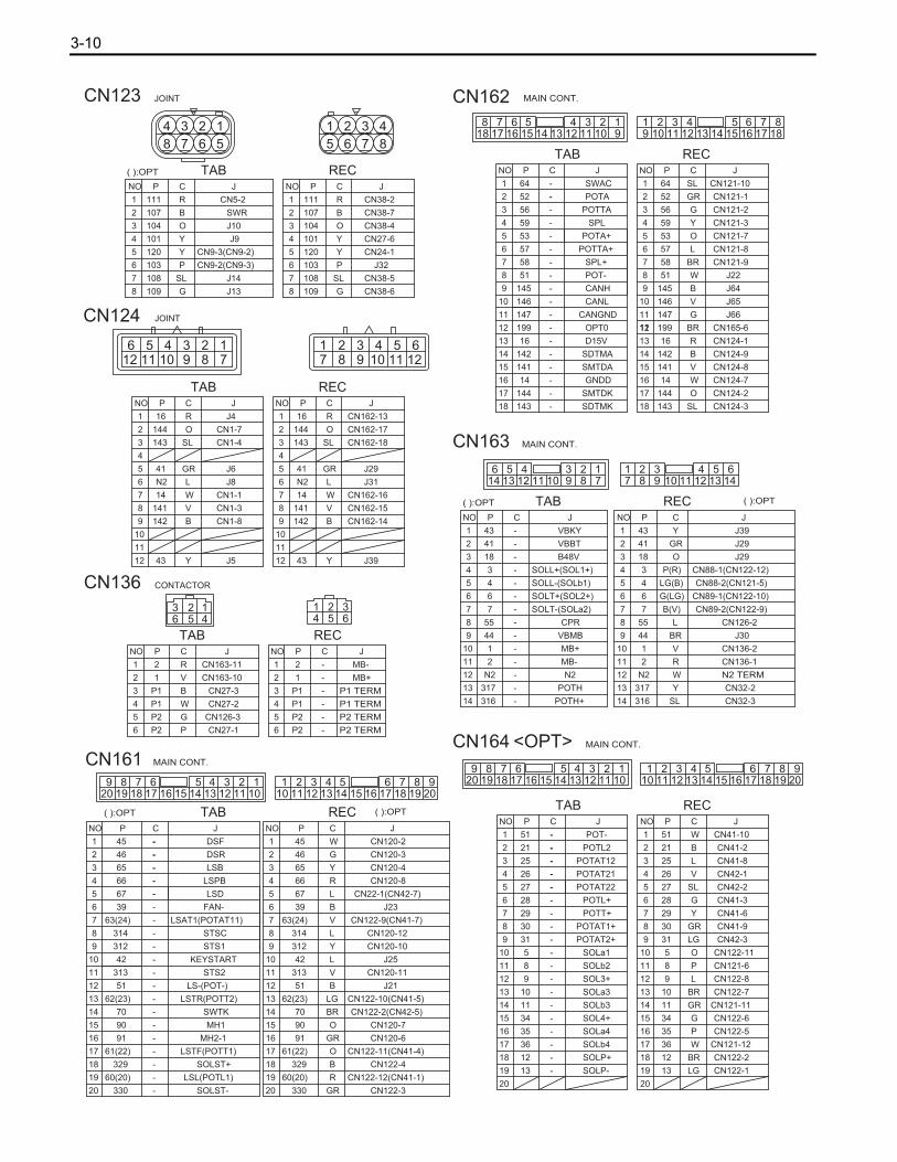
3-10
6
CN124
75432
118 91
106 5 4 3 2
121
10 9 811 7
J5
CN1-8
CN1-3
J4
CN1-1
J8
J6
CN1-4
CN1-7
Y43
B142
V141
R16
W14
LN2
GR41
SL143
O144
J39Y43
CN162-14B142
CN162-15V141
CN162-13R16
CN162-16W14
J31LN2
J29GR41
CN162-18SL143
CN162-17O144
JOINT
1212
1111
NO P C J NO
3
7
P C J
1
2
1
2
4
5
3
7
4
5
66
9 9
88
10 10
TAB REC
12
CN24-1Y120
J32P103
CN38-5SL108
CN38-6G109
CN38-2R111
CN38-7B107
CN38-4O104
101 Y CN27-6
104 O J10
107 B SWR
111 R CN5-2
109 G J13
108 SL J14
103 P CN9-2(CN9-3)
120 Y CN9-3(CN9-2)
J9Y101
( ):OPT RECTAB
JOINT
NO P C J
1
2
3
7
4
5
6
88
6
5
4
7
3
2
1
JCPNO
1
5 76
432
8
CN123
4
8 7
123
56
6 6
55
44
NO
3
TABP C J NO
3
RECP C J
1
2
1
2
CN136 CONTACTOR
1 2 34 5 66 5 4
3 2 1
2 R CN163-11
1 V CN163-10
P1 B CN27-3
P1 W CN27-2
P2 G CN126-3
P2 P CN27-1
2 -
-1
P1 -
-P1
P2 -
P2 -
MB-
MB+
P1 TERM
P1 TERM
P2 TERM
P2 TERM
CN165-6BR19911OPT0-199
( ):OPT
( ):OPT
( ):OPT
( ):OPT
MAIN CONT.
MAIN CONT.
MAIN CONT.
MAIN CONT.
CN121-12W36
CN122-6G34
CN122-7
CN121-11
18 18
CN122-5
17 17
16 16
15 15
14 14
13 13
12 12 CN122-8
11 11 CN121-6
CN41-9
CN41-3
CN42-1
CN41-6
CN42-2
CN41-8POTAT12
1010
8 8
99
6 6
5
4
7
3
5
4
2
1
2
1
JCP
REC
7
3
NOJCP
TABNO
19 19 CN122-1
20 20
POTL2
POT-
POTAT22
POTAT2+
POTAT21
POTL+
POTT+
POTAT1+
SOLa1
SOLb2
SOL3+
SOLa3
SOLb3
SOL4+
SOLa4
SOLP-
SOLb4
51
21
25
26
27
28
29
30
31
8
5
9
10
11
35
13
-
-
-
-
-
-
-
-
-
-
CN41-2
CN41-10
CN122-11
CN42-3
-
-
-
-
-
-
-
-
-
-
-
-
-
W
B
L
V
SL
G
Y
GR
LG
O
P
L
BR
GR
P
LG
12 BR CN122-2SOLP+-
36
34
51
21
25
26
27
28
29
30
31
8
5
9
10
11
35
13
12
CN32-3SL316 - POTH+ 316
329
330
60(20)
91
70
62(23)
51
42
313
312
314
63(24)
39
67
66
65
46
45
90
61(22)
- SOLST+ CN122-4B329
SDTMK 143
144
14
141
142
16
147
146
145
51
58
57
53
59
56
52
64
SL
O
W
V
B
R
G
V
B
W
BR
L
O
Y
G
GR
SL
-143 CN124-3
CN124-2
CN124-8
51 2 3 4 6 7 89 10 11 12 13 14 15 16 17 18
CN124-1
CN124-9
16
142
141
18
14
18
CN124-7
17 17
16 16
15 15
14 14
13 13
12 12
11 11 J66147
51 J22
CN121-8
18 17 16 15 14 13 12 11 10 98 7 6 4 3 2 1
53
CN121-3
CN121-9
CN121-7
CN121-2
CN162
POTTA
1010
8 8
99
58
6 6
5
4
7
3
5
4
2
1
2
1
JCP
REC
7
3
NOJCP
TABNO
57
59
56
5
POTA
SWAC
POTA+
CANH
SPL
POTTA+
SPL+
POT-
CANL
CANGND
D15V
SDTMA
SMTDA
GNDD
52
64
146
145
144 SMTDK
-
-
-
-
-
-
CN121-1
CN121-10
J65
J64
-
-
-
-
-
-
-
-
-
-
-
-
-
-
-
-
-
-
-
-
-
-
-
-
317
N2
2
1
44
55
7
6
4
3
18
41
43
14
13
N2 TERMWN2N2
14
13 317 POTH Y CN32-2
CN88-1(CN122-12)P(R)SOLL+(SOL1+)3
CN89-1(CN122-10)G(LG)SOLT+(SOL2+)6
CN89-2(CN122-9)B(V)SOLT-(SOLa2)7
J30BRVBMB44
CN88-2(CN121-5)LG(B)SOLL-(SOLb1)4
J39YVBKY43
614 13
5124
11 1039 8
271 651
12 12
11 2 MB- 11 R CN136-1
55 CPR L CN126-2
J29
J29
CN163
B48V
VBBT
1010
8 8
99
6 6
5
4
7
3
5
4
2
1
2
1
JCP
REC
7
3
NOJCP
TABNO
O
GR
18
41
2 3 413 147 8 9 10 11 12
CN136-2VMB+1
GR
R
GR
BR
LG
B
V
L
Y
L
V
B
L
R
Y
G
W
-
-
-
-
-
-
-
-
-
-
-
-
-
-
CN120-10
J25
CN120-2
CN120-3
-
-
-
-
-
-
-
-
-
-
330
60(20)
91
70
62(23)
51
42
313
312
314
63(24)
39
67
66
65
46
45
LSTF(POTT1)
SOLST-
LSL(POTL1)
MH2-1
MH1
SWTK
LSTR(POTT2)
LS-(POT-)
STS2
KEYSTART
STSC
LSAT1(POTAT11)
FAN-
LSPB
STS1
LSD
DSF
DSR
CN122-32020
CN122-12(CN41-1)1919
NO
TABP C J NO
3
7
RECP C J
1
2
1
2
4
5
3
7
4
5
66
9 9
88
10 10
LSB CN120-4
CN22-1(CN42-7)
CN122-9(CN41-7)
CN120-8
J23
CN120-12
CN120-111111
J211212
1313
1414
1515
1616
1717
CN120-6
1818
CN122-2(CN42-5)
CN122-10(CN41-5)
90 O CN120-7
61(22) O CN122-11(CN41-4)
181716151413121198764321 5
20191019205 12346789
101112131415161718
CN161<OPT>CN164
18 17 16 15 14 13 12 11 109 8 7 6 4 3 2 15
20 19 10 19 2051 2 3 4 6 7 8 9
11 12 13 14 15 16 17 18

3-11
BACK RELAY
NO
3
6
TABP C J NO
3
6
RECP C J
1
2
1
2
4 4
5 5
CN165
J19
G
103
N1
16
199
43
654321
6 5 43 2 1
O CN9-3
Y
L J11
R J70
CN165-4103
BR CN161-10
103 G CN165-5
198 GR CN38-3
CN38-3GR198OUT-W198
CN161-10BR199 IN-
16
N1
43
IN+
GND
OUT+
J70R
J11L
Y
CN9-3O
123456
1 2 34 5 6
43
199
16
N1
103
W
B
R
W
J19
CN165
55
44
2
1
2
1
JCP
REC
6
3
NOJCP
TAB
6
3
NO
BACK RELAY
EXCEPTEZ PEDAL
EZ PEDAL

3-12
CN165-5
J70
(198,GR)
CN23-1
CN38-3
J66
CN162-11
CN112-3
(147,G)
CN109-6
CN110-6
CN111-6
J65
CN162-10
CN112-2
(146,V)
CN109-4
CN110-4
CN111-4
J64
CN162-9
CN112-1
(145,B)
CN109-3
CN110-3
CN111-3
JOINT
J1
(51,B)
CN90-2
CN120-1
CN6-1
CN9-6(CN9-1)
CN15-1
CN84-2
CN19-2
CN124-1
CN1-2
(16,R)
J4 CN19-1
CN124-12
CN12-2
CN29-2
CN9-8
CN9-7(CN9-6)
(43,Y)
J5
CN29-1J6
(41,GR)
CN3-2
CN124-5
CN13-6
CN45-1
CN46-2CN46-1
SWR
CN5-1
CN123-4
CN45-2
(101,Y)
J9
J8
(N2,L)
CN8-10
CN17-1
CN13-5
CN13-1
CN124-6H
CN17-5
CN123-8
CN8-13
(109,G)
J13 CN17-4
CN13-4
CN123-7
CN8-12
(108,SL)
J14
CN165-2 CN45-4J11
(102,G)
CN13-3
CN17-3
CN122-1
CN21-2
CN87-4
(51,LG)
J2
CN11-2
CN87-2
CN17-2
J10
(104,O)
CN123-3
CN46-4
CN13-2
CN14-3,CN18-3
CN13-1,CN17-1
CN16-2,CN20-2
(N2,W)
J51
J3
(51,W)
CN121-4
CN26-1
CN86-3
CN90-8
J32
(103,P)
CN23-1
CN38-3
CN123-6
CN165-3 CN38-1
CN124-12
CN163-1
(43,Y)
J39
CN50-1 CN113-1
CN163-9
CN27-4
(44,BR)
J30
CN114-1
CN24-2 CN38-8
N2 TERMINAL
CN124-6
CN23-2
(N2,L)
J31
CN38-2
J53
(111,SL)
CN31-2
CN34-2
CN31-1
CN34-1
CN38-4
(104,G)
J55
CN23-2-2
J54
(N2,W)
CN31-4
CN34-6
CN38-8
CN36-2
FB
J22
(51,W)
CN121-4
CN32-1
CN162-8
J27
(78,P)
CN58-1
CN110-10
CN59-3
CN111-2
J26
(86,P)
CN55-1
CN111-10
CN56-3
CN109-1
J28
(82,P)
CN52-1
CN109-10
CN53-3
CN50-2
J23
(39,B)
CN161-6
CN113-2
CN114-2
CN161-12
CN120-1
CN22-2(CN42-8)
(51,B)
J21
CN122-1
CN161-10
CN111-7
J25
(42,L)
CN110-7
CN109-7
J29
(41,GR)
CN27-5
CN124-5
CN163-2
CN163-3
( ):OPT
CN74-2
(9,L)
CN122-8
CN75-2
J47
CN74-3
(6,LG)
CN75-3
J46
CN122-10
(3,R)
J45
CN75-4
CN122-12
CN74-4
(34,G)
J48
CN75-1
CN122-6
CN74-1
(51,W)
CN79-4
CN41-10
CN77-4
J49
CN78-4
CN80-4
CN85-1

3-13
TABREC
TABREC
TABREC
SWK
TABREC
TABREC
FRY
H COM
NO
NC
COM
NO
NC
LSTF
LSTR
SOLLSOLT
TA
BR
EC
TA
BR
EC
TABREC
LF-L
LC-L
LH-L
TABREC
TABREC
TABREC
LSD
TABREC
TABREC
RECTAB
TABREC
RECTAB
TABREC TAB
REC
TABREC
TA
BR
EC
TA
BR
EC
TA
BR
EC
RE
CT
AB
RECTAB
RECTAB
RECTAB
TABREC
TABREC
RE
CT
AB
RE
CT
AB
TA
BR
EC
TA
BR
EC
TA
BR
EC
TABREC
TABREC
TABREC
BATT
AMPRE
CT
AB
RE
CT
AB
TABREC
TABREC
RE
CT
AB
RE
CT
AB
RE
CT
AB
RE
CT
AB
TA
BR
EC
TABREC
TABREC
LBU-RLT-RLST-R
LF-RR LF-LLLT-LLST-L
TABREC
TABREC
TABREC
TABREC
TABREC
TABREC
TABREC
TABREC
TABREC
TABREC
TABREC
SWR
TABREC
TA
BR
EC
COM
NO
NC
RECTAB
TRY
TABRECTAB
REC
TABREC
TABREC
TABREC
TABREC
TABREC
HRY
TABREC
LSD
TABREC
TA
BR
EC
RE
CT
AB
RE
CT
AB
RE
CT
AB
RE
CT
AB
SWL
SWD
SWH
LSPB
DISPLAY
BACKRELAY
TABREC
TABREC
TABREC
FANEX
TA
BR
EC
CN50
CN120CN121
ONLY EZ PEDALCN165
<STD>(EXCEPT MINI -LEVER OPT)
<LEVER CONT. UNIT>
REC
<MINI-LEVER OPT>
SST
CN3
CN19
CN9
CN8
SWL
SWH
SWD
CN164
(101,Y)J9
(107,B)CN123-2
CN43
N2 TERMINAL
<MINI-LEVER OPT>
CN4
<COMPARTMENT LAMP OPT>
(117,SL)
(N1,L)CN96
RECTAB
SWCMP
LCMP
CN27
F6 F4F5
CN45
CN21
CN46
CN124 CN123 CN122
CN98
<KEY-LESS-KEY OPT>
<MINI-LEVER OPT>
CN41CN42
CN85 CN80(4)
CN79(3)
CN78(2)
CN77(1)
LIFT LEVER
TILT LEVER
ATT1 LEVER
ATT2 LEVER
SWTK
CN32
VRAH
CHI
CN24 (F)
CN23(R)
CN31CN34
WL R B
CN36CN23-2
BZ LWFB
CN38
CN22
AMD
RH
AMD
LH
SSD
STMD
W
V
U
CN52
CN53
SSD
STMD
W
V
U
CN58
CN59
W
V
U
+
-
CN110
DRIVE CONTROLUNIT LH
DRIVE CONTROLUNIT RH
CN109
-
+
U
V
W
SSP
STMP
CN55
CN56
U
V
W
-+
P3P1
CN136
CONTACTOR PANEL
+
W
V
U
-
CN111
PUMP CONTROLUNIT
CN163
CN162
CN126
CN161
CN112
R
FANEX
CN114
CN113
FANEX
MAIN CONTROL PANEL
CN9
<DIRECTIONAL CONTROL PEDAL OPT>
SOLST
SPL
SWMH1
CN90
CN91
CN92
CN74
CN75
SOL AT2L
SOL AT1L
SOL TR
SOL LU
SOL AT2U
SOL AT1U
SOL TF
SOL LD
CN76
SOL
CN86
VRAT
TILT
LF-R
LC-R
LH-R
SWK
CN20
CN16
CN12
CN29BR
R
LSATT
LSL
BR
NC
NO
COM
NC
NO
COM
R
(N2,L)J8
(48,P)CN3-1
R
SL
R
BR
CN70
CN15
CN89
CN88
CN87CN11
CN84
CN1
CN26
LSB
LSST
CN6
CN5
CN18
CN17
CN13
CN14
CN4
ACCEL
VRAD
SWTK
CO
NN
ECTI
NG
DIA
GR
AM

3-14
ELEC
TRIC
WIR
ING
DIA
GR
AM

Published by
1st Printing: Dec. 2005
Pub. No. CU341
Printed in Japan
C


