Embed Size (px)
Citation preview
ELEKTROTECHNISCHE WERKEFRITZ DRIESCHER & SÖHNE GMBHD-85366 MOOSBURG • TEL. +49 87 61 6 81-0 • FAX +49 87 61 68 12 30http://www.driescher.com [email protected]
785E3K
WEL
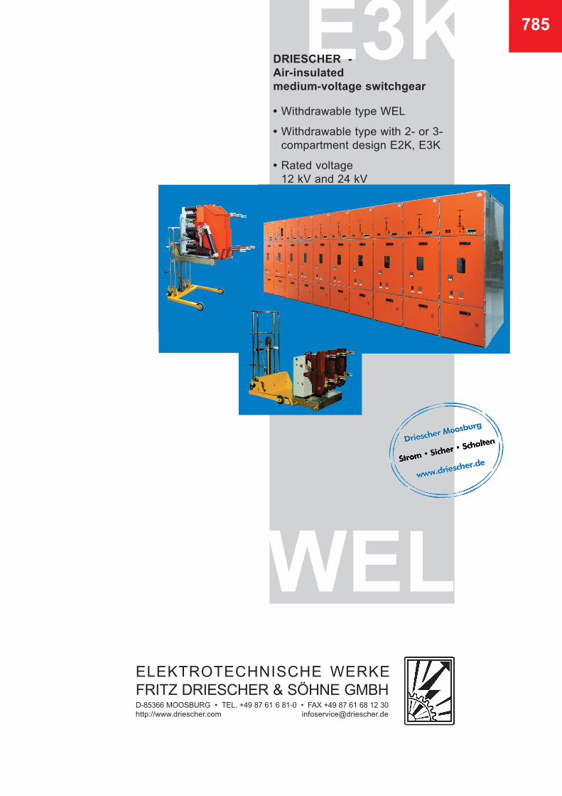
DRIESCHER -
Air-insulated
medium-voltage switchgear
• Withdrawable type WEL
• Withdrawable type with 2- or 3- compartment design E2K, E3K • Rated voltage 12 kV and 24 kV
2
General information
DRIESCHER - Air-insulated medium-voltage switchgear
of withdrawable design
In compliance with EN 62271-200
Content
• 2 General information, operating conditions
• 3 Design features and equipment
• 4 Switchpanels in withdrawable design – circuit-breaker (WEL)
• 6 Switchpanels in withdrawable design – circuit-breaker and compartment design (E2K/E3K)
• 8 The withdrawable unit with circuit-breaker or switch-fuse combination, advantages
These air-insulated medium-voltage switchpanels in withdrawable design have been designed to deliver a very reliable yet cost-efficient power supply and ope-rating safety. The withdrawable design enables a visible isolating distance of the circuit-breaker or switch-fuse combi-nation and consequently and disconnector free design of the switchpanel.
Design forms: Withdrawable design circuit-breaker Type (WEL): - Switch panel with circuit-breaker - With inserting insulating plate - Optionally with earthing switch and motor-operated mechanism, as well as with current and voltage transformers Withdrawable design circuit-breaker / switch-
fuse combination with 2- or 3-compartment
design Type (E2K, E3K):
- Switchpanel with circuit-breaker or switch-disconnector with automatic 2 or 3-chamber partitions.
(in this case the insulating plate is omitted) - optionally with earthing switch and motor-operated mechanism as well as with current and voltage transformers The panel types can be provided as individual panels or as switchgear where the equipment (earthing switch, current and voltage transformers), order of panels etc. can be determined by the customer. The metal encapsulated medium-voltage switch panels are designed to meet the demand in networks of municipal utility corporations and supply corporati-ons in industry and public buildings. The type-tested switchpanels are in compliance with the requirements of DIN EN 62271-200, protection class IP 4X. The resistance to accidental arcs has been rated at 16 kA, 25 kA and 31,5 kA; 1s by a neutral testing insti-tute. The installed switches are designed in complian-ce with the corresponding switchgear standards. Technical data of the installed switches are to be found - in brochurev727 for switch-fuse combination H 27 - in brochure 731 for earthing switches - in brochure 747 for circuit-breakers
The switch panels in withdrawable design are instal-led in closed electrical operating areas which are only to be entered by special staff and appropriately instructed personnel. Installation can be carried out at levels of up to 1000 meters above sea level.
At levels above 1000 meters the rated insulating level of the switchgear must be corrected accor-dingly. The switch panels are designed for use under normal operating conditions in compliance with EN 62271-1.
Operating conditions
785
3
Design features:
• Metal-encapsulated, air-insulated switchpanel • The switchpanel frame is of a screwed, hot-galvanized composite design • Busbar partitioning from panel to panel with FRP-insulating plates and three leadthroughs (optional) • Single-wing, reinforced solid sheet doors (16 kA-31.5 kA) with laminated safety glass and cylinder lock • Integrated secondary device module with separate door in front of busbars • Covers at the top of galvanized steel sheet for pressure relief; closed at the back and open at the bottom (optional full covering at the bottom). Pressure relief can be in upward or downward direction • Connecting cables are conducted into the switch panels from below on two-dimensional adjustable crossbars • All installed switches can be manually operated or with motor-operated mechanism with closed panel door
Equipment:
• In switch panels without chamber partitions there is a insula- ting protective barriere provided. This can be inserted with switchgears in isolated position and with closed doors • In switch panels with 2 or 3-compartments the compartments are automatically covered by a self-closing metal shutter in isolated position. (here the inserting insulating plate is omitted) • Current and voltage transformer • For earthing and short-circuiting there are make-proof earthing switches with motor-operated mechanism available. If required it is possible to install appropriate surge voltage protectors in the panel. • Incorrect operation is ruled out through power-free interlocking of the devices towards each other. • Mimic diagram with integrated mechanical position indicator on the front (electrical position display optional) • available in all RAL colours
Design features and equipment
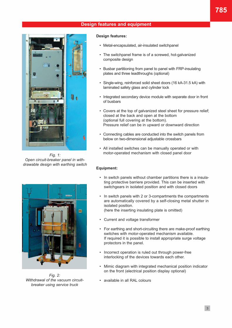
Fig. 1: Open circuit-breaker panel in with-
drawable design with earthing switch
Fig. 2: Withdrawal of the vacuum circuit-
breaker using service truck
785

4
Switchpanels in withdrawable design Type (WEL)
Fig. 3: 12 kV Circuit-breaker panel (WEL)
• Disconnector free, withdrawable design Type (WEL)
• Metal-encapsulated and air-insulated
• High degree of operating safety based on sturdy, patented
2-spindle design of withdrawable cassette
• For partitioning with circuit-breaker in isolated position there is an Insulating protective barrier available for inserting
• All switching operations including the moving of the circuit- breaker into isolated position are carried out behind closed panel doors in order to guarantee maximum personal protection
• Variable locking options for the complete switch panel in order to ensure maximum operating safety
• Protection up to IP4X
• Weight when fully equipped approx. 1000 kg
Technical data of switchpanel
Rated voltage Ur 12 kV 24 kV
Lightning impulse withstand voltage Up 75 kV 125 kV Rated short-duration power-frequency withstand voltage Ud 28 kV 50 kV Rated current Ir 630 A and 1250 A2) Rated short-time current Ik 31.5 kA 31.5 kA Rated short-circuit duration tk 3 s1) 3 s1) Rated peak short-circuit current Ip 80 kA 80 kA Rated frequency fr 50 Hz 50 Hz
1) Rated short-circuit duration under arcing influence 1 s. 2) higher currents upon request
Technical data of switches Vacuum circuit-breaker
Rated voltage Ur 12 kV 24 kV
Rated current Ir up to 1250 A2) up to 1250 A2)
Rated short-time current Ik up to 31.5 kA up to 31.5 kA
Rated peak short-circuit current Ip up to 80 kA up to 80 kA
785

5
Circuit-Breaker
Withdrawable cassette
Earthing switch
Current transformer
Voltage transformer
Secondary relay
Insulating protective barrier
Circuit-breaker in OFF-Position
Circuit-breaker with auxiliary truck
Circuit-breaker in ON-Position
Withdrawable switchpanels (WEL)
12 kV
Width: 800 mm • 900 mm Depth: 1100 mm Height: 2100 mm with simple secondary relay module 2) 2280 mm with updated secondary relay module 2460 mm with high secondary relay module
24 kV Width: 800 mm 1) • 900 mm 1) • 1000 mm Depth: 1100 mm Height: 2100 mm with simple secondary relay module 2280 mm with updated secondary relay module 2460 mm with high secondary relay module
Panel dimensions:
1) These panel widths are equipped with FRP plates for additional insulation 2) Height of relay modules depending on equipment
*
*
The Insulating protective barrier can be inserted when the circuit-breaker is in isolated position (also possible in lockable design)
1
1
2
2
3
3
4
4
5
5
6
6
7
1
2
3
4
5
6
7
785
6
Withdrawable switchpanels in 2- or 3-compartment design (EK)
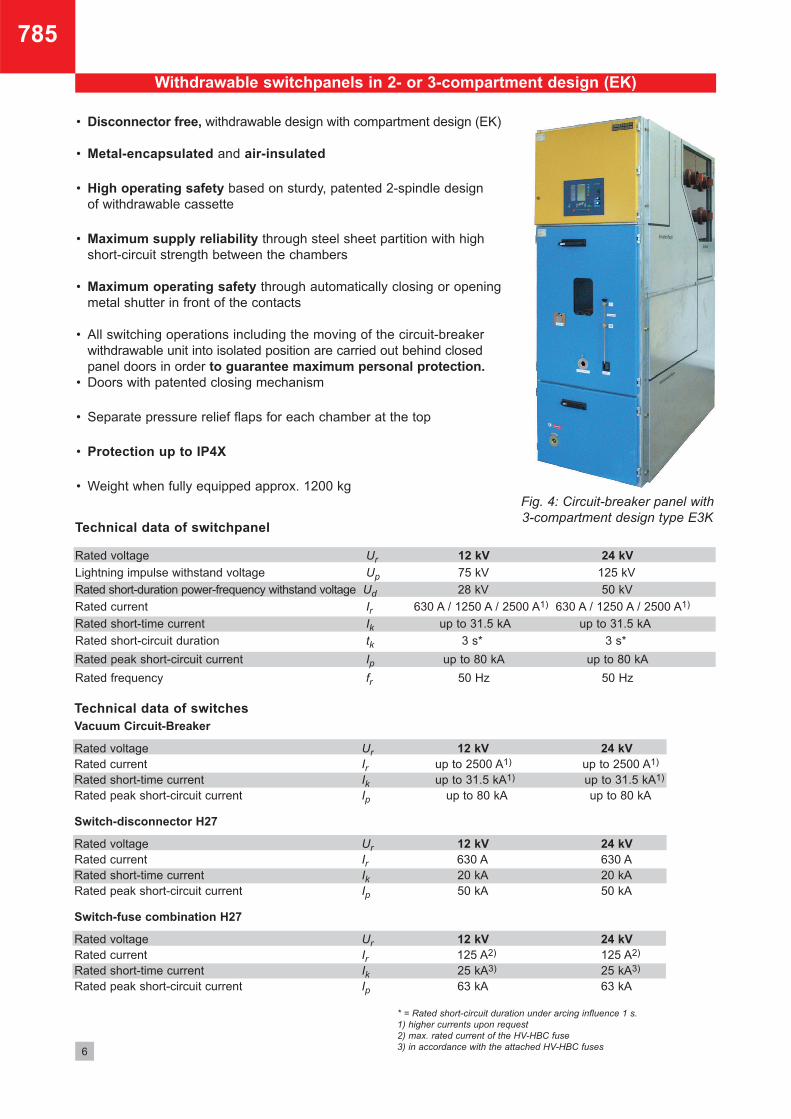
Fig. 4: Circuit-breaker panel with 3-compartment design type E3K
• Disconnector free, withdrawable design with compartment design (EK) • Metal-encapsulated and air-insulated
• High operating safety based on sturdy, patented 2-spindle design of withdrawable cassette
• Maximum supply reliability through steel sheet partition with high short-circuit strength between the chambers • Maximum operating safety through automatically closing or opening metal shutter in front of the contacts • All switching operations including the moving of the circuit-breaker withdrawable unit into isolated position are carried out behind closed panel doors in order to guarantee maximum personal protection. • Doors with patented closing mechanism
• Separate pressure relief flaps for each chamber at the top
• Protection up to IP4X
• Weight when fully equipped approx. 1200 kg
Technical data of switchpanel
Rated voltage Ur 12 kV 24 kV
Lightning impulse withstand voltage Up 75 kV 125 kV
Rated short-duration power-frequency withstand voltage Ud 28 kV 50 kV
Rated current Ir 630 A / 1250 A / 2500 A1) 630 A / 1250 A / 2500 A1)
Rated short-time current Ik up to 31.5 kA up to 31.5 kA
Rated short-circuit duration tk 3 s* 3 s*
Rated peak short-circuit current Ip up to 80 kA up to 80 kA
Rated frequency fr 50 Hz 50 Hz
Technical data of switches Vacuum Circuit-Breaker
Rated voltage Ur 12 kV 24 kV
Rated current Ir up to 2500 A1) up to 2500 A1) Rated short-time current Ik up to 31.5 kA1) up to 31.5 kA1)
Rated peak short-circuit current Ip up to 80 kA up to 80 kA Switch-disconnector H27
Rated voltage Ur 12 kV 24 kV
Rated current Ir 630 A 630 A Rated short-time current Ik 20 kA 20 kA Rated peak short-circuit current Ip 50 kA 50 kA Switch-fuse combination H27
Rated voltage Ur 12 kV 24 kV
Rated current Ir 125 A2) 125 A2) Rated short-time current Ik 25 kA3) 25 kA3) Rated peak short-circuit current Ip 63 kA 63 kA
* = Rated short-circuit duration under arcing influence 1 s. 1) higher currents upon request 2) max. rated current of the HV-HBC fuse 3) in accordance with the attached HV-HBC fuses
785
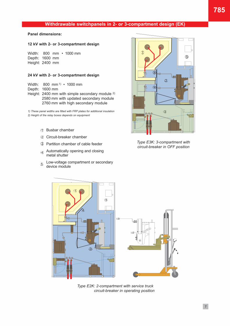
Type E2K: 2-compartment with service truck circuit-breaker in operating position
7
Withdrawable switchpanels in 2- or 3-compartment design (EK)
Type E3K: 3-compartment with circuit-breaker in OFF position
12 kV with 2- or 3-compartment design
Width: 800 mm • 1000 mm Depth: 1600 mm Height: 2400 mm
24 kV with 2- or 3-compartment design
Width: 800 mm 1) • 1000 mm Depth: 1600 mm Height: 2400 mm with simple secondary module 2) 2580 mm with updated secondary module 2760 mm with high secondary module
Panel dimensions:
1) These panel widths are fitted with FRP plates for additional insulation 2) Height of the relay boxes depends on equipment
Busbar chamber Circuit-breaker chamber Partition chamber of cable feeder Automatically opening and closing metal shutter Low-voltage compartment or secondary device module
1
1
2
3
4
4
2
4
1
2
3
4
5
5
5
785
• Separator-free design • All switching operations including the moving of the circuit-breaker into isolated position are carried out behind the closed door on the front to ensure maximum personal protection
• Very safe and reliable moving of the withdrawable
cassette based on the high quality ball-brearing rollers and patented 2-spindle method • Simple operation and optimal access of the
device components • Safe and reliable earthing of withdrawable cassette through the metal rollers • The used DRIESCHER switches are characterized by an exceptionally high service life and minimum
maintenance
• Very flexible based on compact dimensions and many different equipment possibilities
• Cost-efficient, service friendly and variable design through easily removable circuit-breaker by means of: - auxiliary truck equipped with docking unit, also non-tilt, vertically adjustable design with operator friendly features (Page 5) - service truck additionally fitted with an hydraulic unit for lifting and lowering the circuit-breaker (Page 7)
ELEKTROTECHNISCHE WERKEFRITZ DRIESCHER & SÖHNE GMBHD-85366 Moosburg • Phone: +49 8761 681-0 • Fax: +49 8761 681-137www.driescher.com [email protected]
Order no. 3-81707851 • 07-18
Dimensions, weights, diagrams and descriptions in this brochure are non-binding. Subject to change without notice.
Printed on chlorine free bleached paper. For nature´s sake.
STROM • SICHER • SCHALTEN
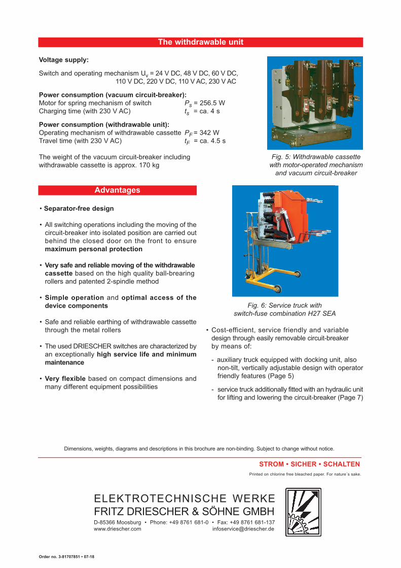
Voltage supply: Switch and operating mechanism Uv = 24 V DC, 48 V DC, 60 V DC, 110 V DC, 220 V DC, 110 V AC, 230 V AC Power consumption (vacuum circuit-breaker): Motor for spring mechanism of switch Ps = 256.5 W Charging time (with 230 V AC) ts = ca. 4 s Power consumption (withdrawable unit): Operating mechanism of withdrawable cassette PF = 342 W Travel time (with 230 V AC) tF = ca. 4.5 s The weight of the vacuum circuit-breaker including withdrawable cassette is approx. 170 kg
The withdrawable unit
Advantages
Fig. 5: Withdrawable cassette with motor-operated mechanism
and vacuum circuit-breaker
Fig. 6: Service truck with switch-fuse combination H27 SEA