Embed Size (px)
Citation preview
National Fire Protection Association 1 Batterymarch Park, Quincy, MA 02169-7471 Phone: 617-770-3000 • Fax: 617-770-0700 • www.nfpa.org
Agenda Technical Committee on Lightning Protection
Standard for the Installation of Lightning Protection Systems Second Draft Meeting
Charlotte, NC July 27 - 30, 2015
Item 15-7-1. Call to Order
Item 15-7-2. Roll Call and Introductions
Item 15-7-3. Approval of Meeting Agenda
Item 15-7-4. Approval of Meeting Minutes
Item 15-7-5. Staff/Chair Remarks
Item 15-7-6. Task Group Reports
Item 15-7-7. Public Comments and Second Revisions
Item 15-7-8. Old Business
Item 15-7-9. New Business
Item 15-7-10. Review Dates and Times for Future Meetings/Conference Calls
Item 15-7-11. Adjournment and Closing Remarks
NFPA 780 FIRST DRAFT MEETING MINUTES Technical Committee on Standard for the
Installation of Lightning Protection Systems September 22 - 26, 2014 Crown Plaza Denver
Denver, CO
Attendance: See attached for both members and guests present. Item 14-9-1 Call to Order
The Technical Committee meeting was called to order at 8:05 am by Chair John Tobias. John provided opening comments and welcomed members and guests. Item 14-9-2 Roll Call and Introductions
All TC members and guests were asked to sign in and verify their affiliation. New committee members were introduced. Item 14-9-3 Approval of Meeting Agenda The meeting agenda was approved. Item 14-9-4 Approval of Meeting Minutes
The meeting minutes of April 30, May 1 & 2, 2014 was approved. Item 14-9-5 Staff/Chair Remarks and Using the New Process The Chair thanked all for their attendance and participation. The Chair made opening remarks and outlined the plan for addressing Public Inputs (PIs) and Committee Inputs (CIs) by task group. NFPA Staff reviewed the First Draft process and operation of the TerraView system for processing items. Item 14-9-6 Task Group Reports Task Group reports were deferred to item 14-9-7. As task groups were operating for approximately six weeks to formulate recommendations on resolution of PIs to the full TC, their work was integrated into item 14-9-7. The following represents the NFPA 780 Task Groups:
Airfield Lighting - Carl J.
Bridges/Piers - Mitch G.
Editorial - Steve H.
Explosives - Jo. C.
Fabric Structures – Doug F.
Grounding & Bonding - Mitch G.
Personal Safety – Steve H.
References – Mark M.
Risk Assessment – Mitch G./Dave M.
Smart Structures – John T.
Solar Panel – Matt C.
Strike Terminations/Tall Structures – Tom H.
Surge Protection – Mitch G.
Tanks – Bruce K.
Watercraft – Ewen T.
Wind Turbine – Matt C. Item 14-9-7 Public Inputs, Committee Inputs and First Revisions

PIs/CI s were grouped into areas of responsibilities assigned to the task groups (see item 14-9-6). 251 PIs and 5 CIs were processed resulting in 132 FRs for Public Comment. Item 14-9-8 Old Business None. Item 14-9-9 New Business
The Chair discussed comments on lightning protection received from industry sources. The TC reviewed these inputs and found many were addressed by PIs currently under consideration. Item 14-9-10 Review Dates and Times for Future Meetings/Conference Calls
No conference calls are scheduled. The next full committee meeting (SDM) is scheduled for July 27 – 31, 2015 in Charlotte, NC. Item 14-9-11 Adjournment and Closing Remarks
The meeting adjourned at 6:30 pm on September 26. The Chair thanked staff and members for their past and continued efforts on NFPA 780.

NFPA 780 First Draft Meeting
Committee Members in Attendance:
John Tobias, Chair US Department of the Army
Samuel Barrack, Principal Consolidated Nuclear Security, LLC
Christopher Batchelor,
Principal
US Department of the Navy
Joanie Campbell, Principal US Department of the Air Force
Josephine Covino, Principal US Department of Defense
Ignacio Cruz, Principal Cruz Associates, Inc.
Robert Daly, Principal Los Alamos National Laboratory
Douglas Franklin, Principal Thompson Lightning Protection, Inc.
Mitchell Guthrie, Principal Engineering Consultant
Thomas Harger, Principal Harger Lightning Protection, Inc.
William Heary, Principal Heary Brothers Lightning Protection
Carl Johnson, II, Principal AVCON, Inc.
David McAfee, Principal Lightning & Fire Protection Consultant
Robley Melton, Principal Alliance for Telecommunications
Industry
Mark Morgan, Principal East Coast Lightning Equipment, Inc.
Luke Pettross, Principal Lightning Eliminators & Consultants,
Inc.
Christine Porter, Principal Intertek Testing Services
Lon Santis, Principal Explosives Risk Managers, LLC
Russell Stubbs, Principal CenturyLink
Ewen Thomson, Principal Marine Lightning Protection, Inc.
Harold VanSickle, Principal Lightning Protection Institute
Richard Bouchard, Alternate Underwriters Laboratories, Inc.
Stephen Humeniuk, Alternate United Lightning Protection Associaton
Paul Svendsen, Alternate National Lightning Protection
Corporation
Richard Roux, Staff Liaison NFPA
Guests in Attendance: Simon Larter Dobbyn Lightning Protection
George Dudkowski Underwriters Laboratories

Public Comment No. 16-NFPA 780-2015 [ Global Input ]
Type your content here ...I was unable to make comments to individual sections of NFPA 780. Icould search for submitted or unsubmitted comments but no where did I see a comment box likethis to actually type in the comments.
1. Section 8.4.1 requires explosives facilities to have a "ground ring conductor." Is a "ground ringconductor" the same as a "ground ring electrode?" Or are they different? Could an explosivesfacility have a ground ring conductor connected to a ground ring electrode, or would that bereduntant? There is no defination of a ground conductor or ground ring conductor in chapter 3. Ifa ground ring conductor is the ground ring electrode why have other grounding methods listed(concrete-encased electrodes (8.4.2), Radials (8.4.4), Plates (8.4.5)?
2. Section 8.7.2 Piers and Wharfs - This seems to require 3 ground loop conductors. One for theLP, one for connecting metal objects on the pier (bollards, safety rails, RR tracks) and if we chose toconnect to a water ground (salt or fresh water) then it requires its own ground loop conductor. Allof these ground loop conductors must be interconnected. A water ground, although very effective,is not listed as one the allowable grounding mediums (hint - include water grounds as authorizedgrounding types). I suggest that we allow piers and wharfs to have one "ground loop electrode"and connect the LP, the RR track and the salt water ground to the same "ground loop electrode."
3. Chapter 4, tables 4.1.1.1.1 and 4.1.1.1.2 - Consider allowing the use of steel (or at least galvinized steel)in LP applications. To do so you'd need to make changes to the two referenced tables as there is no entryfor steel or galvinized steel. Steel is authorized for catenary LP systems but what sizes? What weights per1000 ft? Do we use the copper columns or the aluminum columns? From some internet research I've donesteel is close to the conductivity of aluminum. So, I recommend we use the aluminum column for steelapplication.
4. Section 8.7.3 - I find this section flawed for two reasons, one it addresses all cranes regardless of size oruse, secondly the criteria seems to address static dissipation not lightning protection. If I were to fix this I'drecommend wording that would require application when explosives not in DOT packaging are being liftedby the crane. What risk is there when a bridge crane lifts an ISO container of munitions packaged to DOTstandards on an ammo pier? Chances are we are not loading ammo on a ship during a thunderstorm, buteven if we did the ISO container is a "poor man's faraday cage." Secondly, it would be extremely difficult toelectrically isolate the cable and hook of a crane from the crane frame (as seems to be required in sections8.7.3.1 and 8.7.3.3) and once again I need two separate (but connected) "ground loop conductors." So, if Ihad a bridge crane on an ammo pier would it require 5 separate "ground loop conductors" (3 for the peir and2 for the bridge crane)? From my perspective the only time I'd want to electrically isolate the cable/hookassembly from the boom is if I was concerned about static spark generation....which is not an LP concern.
5. Section 8.10.7.6 Requires the three-point-fall-of-potential test (3pt-T) for grounding systems of explosivesfacilities. I believe that 3 pt-T is not a viable test when you have a ground loop electrode. The 3pt-T seemsto be more designed for a ground rod system. A ground loop electrode system is a giant ground rod lying onits side. It likely measures to the nearest point on the ground loop electrode and not the loop "as a whole." As far as grounding systems go, a ground ring electrode is considered the best grounding system. If aground ring electrode fails a 3pt-T how would you fix it, you already have the best possible system? Withinthe Army explosives community if a ground loop electrode system fails 3pt-T then we then annotate that lasttest value as the new base line and look for further deterioration. Given the fact that the 3pt-T is not a viabletest of the ground loop electrode and the fact that it is considered to be the ultimate grounding system I seeno reason to conduct a 3pt-T on a ground loop electrode system. I ask that the NFPA 780 committee toconsider exempting ground loop electrode grounding systems from 3pt-T.
Submitted by Greg Heles, US Army Technical Center for Explosives Safety, 918 420-8877.
Additional Proposed Changes
File Name Description Approved
Conductivity_comparisons_of_common_metals.docx
National Fire Protection Association Report http://submittals.nfpa.org/TerraViewWeb/ContentFetcher?commentPara...
1 of 100 5/18/2015 3:44 PM

LP_Issues_submitted_to_DOD_LP_Meeting_March_2015.docx
Statement of Problem and Substantiation for Public Comment
1) Term grounding conductor is used but not defined. Is the same as ground loop electrode? 2) Chapter 8 sections on piers and cranes are vague and seem to require excessive grounding/bonding3) NFPA 780 should allow the use of steel in LP applications4) NFPA should rescind the requirement for doing 3-pt test on structures/locations having ground loop electrode systems
Also, see attached documents to this public comment.
Related Item
First Revision No. 30-NFPA 780-2014 [Section No. 8.4.1]
Submitter Information Verification
Submitter Full Name: Greg Heles
Organization: US Army
Street Address:
City:
State:
Zip:
Submittal Date: Wed Mar 25 14:18:12 EDT 2015
National Fire Protection Association Report http://submittals.nfpa.org/TerraViewWeb/ContentFetcher?commentPara...
2 of 100 5/18/2015 3:44 PM

Public Comment No. 56-NFPA 780-2015 [ New Section after 1.6 ]
1.6.1
Periodic inspections or testing of the completed installation for compliance to the current standardshall be done at intervals determined by the authority having jurisdiction.
Statement of Problem and Substantiation for Public Comment
CI # 123 - adds section for industry commentsAdditional wording added for clarification and discussion.
Related Item
Committee Input No. 123-NFPA 780-2014 [New Section after 1.6]
Submitter Information Verification
Submitter Full Name: HAROLD VANSICKLE
Organization: LIGHTNING PROTECTION INSTITUTE
Street Address:
City:
State:
Zip:
Submittal Date: Thu May 07 10:27:18 EDT 2015
National Fire Protection Association Report http://submittals.nfpa.org/TerraViewWeb/ContentFetcher?commentPara...
3 of 100 5/18/2015 3:44 PM

Public Comment No. 66-NFPA 780-2015 [ New Section after 1.6 ]
1.6.1 Periodic inspections or testing for compliance to this standard shall be done at an intervalas determined by the authority having jurisdiction.
Statement of Problem and Substantiation for Public Comment
I support Public Comment 66. Just like your automobile a LPS requires periodic maintenance. To determine what maintenance needs to be performed an inspection is necessary. Periodic inspections should be performed to determine that the LPS complies with this Standard.
Related Item
Committee Input No. 123-NFPA 780-2014 [New Section after 1.6]
Submitter Information Verification
Submitter Full Name: CARL JOHNSON II
Organization: AVCON INC
Affilliation: none
Street Address:
City:
State:
Zip:
Submittal Date: Sat May 09 12:32:08 EDT 2015
National Fire Protection Association Report http://submittals.nfpa.org/TerraViewWeb/ContentFetcher?commentPara...
4 of 100 5/18/2015 3:44 PM

Public Comment No. 99-NFPA 780-2015 [ New Section after 1.6 ]
1.6.1 Periodic Inspection
Periodic inspections or testing for compliance to this standard shall be done at an interval as
determined by the authority having jurisdiction.
Type your content here ...
Statement of Problem and Substantiation for Public Comment
Mandates that the lightning protection system be inspected or test after the original installation , while providing latitude for the interval at which it will be done.
This is very important. Lightning protection system exists on structures that are over one hundred years old. The owners of those facilities think they have effective lightning Protection.
Related Item
Committee Input No. 123-NFPA 780-2014 [New Section after 1.6]
Submitter Information Verification
Submitter Full Name: STEPHEN HUMENIUK
Organization: WARREN LIGHTNING ROD COMPANY
Affilliation: ULPA
Street Address:
City:
State:
Zip:
Submittal Date: Fri May 15 16:32:43 EDT 2015
National Fire Protection Association Report http://submittals.nfpa.org/TerraViewWeb/ContentFetcher?commentPara...
5 of 100 5/18/2015 3:44 PM

Public Comment No. 54-NFPA 780-2015 [ Chapter 2 ]
Chapter 2 Referenced Publications
2.1 General.
The documents or portions thereof listed in this chapter are referenced within this standard and shall beconsidered part of the requirements of this document.
2.2 NFPA Publications.
National Fire Protection Association, 1 Batterymarch Park, Quincy, MA 02169-7471.
NFPA 70® , National Electrical Code®, 2014 edition.
2.3 Other Publications.
2.3.1 IEC Publications.
International Electrotechnical Commission, 3, rue de Varembé, P.O. Box 131, CH-1211 Geneva 20,Switzerland.
IEC 62305-2, Protection Against Lightning—Part 2: Risk Management, Edition 2, 2010.
2.3.2 ISO Publications.
International Organization for Standardization, ISO Central Secretariat, 1, ch. de la Voie-Creuse, CP 56,CH-1211 Geneva 20, BIBC II, 8 , Chemin de Blandonnet , CP 401 , 1214 Vernier, GenevaSwitzerland.
ISO 1496, Series 1 freight containers — Specification and testing — Part 1: General cargo containers forgeneral purposes, 2013.
2.3.3 UL Publications.
Underwriters Laboratories Inc., 333 Pfingsten Road, Northbrook, IL 60062-2096.
ANSI/UL 1449, Standard for Safety for Surge Protective Devices, 4th edition, August 20, 2014.
2.3.4 Other Publications.
Merriam-Webster’s Collegiate Dictionary, 11th edition, Merriam-Webster, Inc., Springfield, MA, 2003.
2.4 References for Extracts in Mandatory Sections.
NFPA 70® , National Electrical Code®, 2014 edition.
NFPA 115, Standard for Laser Fire Protection, 2012 edition.
Statement of Problem and Substantiation for Public Comment
Updated ISO address.
Related Item
First Revision No. 44-NFPA 780-2014 [Section No. 2.3]
Submitter Information Verification
Submitter Full Name: Aaron Adamczyk
Organization: [ Not Specified ]
Street Address:
City:
State:
Zip:
Submittal Date: Sat May 02 15:58:45 EDT 2015
National Fire Protection Association Report http://submittals.nfpa.org/TerraViewWeb/ContentFetcher?commentPara...
6 of 100 5/18/2015 3:44 PM

Public Comment No. 86-NFPA 780-2015 [ Section No. 3.3.17 ]
3.3.17 Grounding Electrode.
The portion of a lightning protection system, such as a ground rod, ground plate electrode, or groundconductor, that is installed for the purpose of allowing allows lightning current flow to flow into the earth.
Statement of Problem and Substantiation for Public Comment
Text changed for readability by the editorial TC
Related Item
First Revision No. 78-NFPA 780-2014 [Section No. 3.3.17]
Submitter Information Verification
Submitter Full Name: STEPHEN HUMENIUK
Organization: WARREN LIGHTNING ROD COMPANY
Affilliation: ULPA
Street Address:
City:
State:
Zip:
Submittal Date: Fri May 15 08:31:33 EDT 2015
National Fire Protection Association Report http://submittals.nfpa.org/TerraViewWeb/ContentFetcher?commentPara...
7 of 100 5/18/2015 3:44 PM

Public Comment No. 62-NFPA 780-2015 [ Section No. 3.3.23 ]
3.3.23 * Light Base.
An enclosure used as (i) a mounting base for airport for airfield light fixtures and assemblies. The unitserves as , (ii) an isolation transformer housing or , (iii) an electrical junction box, or both. The light baseis cylindrically shaped, with a closed bottom, provisions for cable or conduit entry and exit, and provisionsfor grounding, and is provided with a top flange to mate with the fixture or cover (iv) any combination of theforegoing .
Statement of Problem and Substantiation for Public Comment
PI-129 initiated editorial changes to the Light Base definition which resulted in FR-1. The editorial task group discovered an ambiguity in the proposed new definition. This Public Comment is to correct that ambiguity.
Related Public Comments for This Document
Related Comment Relationship
Public Comment No. 63-NFPA 780-2015 [Section No. A.3.3.23]
Related Item
First Revision No. 1-NFPA 780-2014 [Section No. 3.3.22]
Public Input No. 129-NFPA 780-2014 [Section No. 3.3.22]
Submitter Information Verification
Submitter Full Name: CARL JOHNSON II
Organization: AVCON INC
Affilliation: none
Street Address:
City:
State:
Zip:
Submittal Date: Sat May 09 11:01:04 EDT 2015
National Fire Protection Association Report http://submittals.nfpa.org/TerraViewWeb/ContentFetcher?commentPara...
8 of 100 5/18/2015 3:44 PM

Public Comment No. 18-NFPA 780-2015 [ New Section after 3.3.25 ]
3.3.26
3.3.26 Lightning Protection System (for airfield lighting circuits). A complete underground system ofcounterpoise conductors (guard wires, shield wires), grounding electrodes, bonding jumpers, surgeprotective devices, and other connectors and fittings required to complete the system.
Statement of Problem and Substantiation for Public Comment
PI-75 provides as a Statement of Problem and Substantiation for Public Input - “As far as I know there are not any underground lightning protection systems. Word differently.”
During the task group’s deliberation on PI-75 the task group decided that a clarification of the definition of a lightning protection system was necessary.
Related Public Comments for This Document
Related Comment Relationship
Public Comment No. 17-NFPA 780-2015 [Section No. 3.3.25]
Public Comment No. 19-NFPA 780-2015 [Section No. A.3.3.25]
Related Item
Public Input No. 75-NFPA 780-2014 [Section No. 11.1.2]
Submitter Information Verification
Submitter Full Name: Carl Johnson II
Organization: AVCON, Inc.
Affilliation: none
Street Address:
City:
State:
Zip:
Submittal Date: Sat Mar 28 13:50:17 EDT 2015
National Fire Protection Association Report http://submittals.nfpa.org/TerraViewWeb/ContentFetcher?commentPara...
9 of 100 5/18/2015 3:44 PM

Public Comment No. 17-NFPA 780-2015 [ Section No. 3.3.25 ]
3.3.25 * Lightning Protection System (for aboveground structures) .
A complete system of strike termination devices, conductors (which could include conductive structuralmembers), grounding electrodes, interconnecting conductors, surge protective devices, and otherconnectors and fittings required to complete the system.
Statement of Problem and Substantiation for Public Comment
PI-75 provides as a Statement of Problem and Substantiation for Public Input - “As far as I know there are not any underground lightning protection systems. Word differently.”
During the task group’s deliberation on PI-75 the task group decided that a clarification of the definition of a lightning protection system was necessary.
Related Public Comments for This Document
Related Comment Relationship
Public Comment No. 18-NFPA 780-2015 [New Section after3.3.25]
partial public comment to PI-75, LPSdefinition
Public Comment No. 19-NFPA 780-2015 [Section No.A.3.3.25]
Related Item
Public Input No. 75-NFPA 780-2014 [Section No. 11.1.2]
Submitter Information Verification
Submitter Full Name: Carl Johnson II
Organization: AVCON, Inc.
Affilliation: none
Street Address:
City:
State:
Zip:
Submittal Date: Sat Mar 28 13:35:48 EDT 2015
National Fire Protection Association Report http://submittals.nfpa.org/TerraViewWeb/ContentFetcher?commentPara...
10 of 100 5/18/2015 3:44 PM

Public Comment No. 91-NFPA 780-2015 [ Section No. 3.3.28 ]
3.3.28 Magnetically Shielded.
Enclosing all All or part of an object in enclosed in a metallic grid or continuous screen reducesscreen which reduce the effects of the lightning electromagnetic pulse (LEMP) and consequently the failureof electronic system components.
Statement of Problem and Substantiation for Public Comment
The text as previously written was an action and not a statement.
Related Item
First Revision No. 25-NFPA 780-2014 [Section No. 3.3.27]
Submitter Information Verification
Submitter Full Name: STEPHEN HUMENIUK
Organization: WARREN LIGHTNING ROD COMPANY
Affilliation: ULPA
Street Address:
City:
State:
Zip:
Submittal Date: Fri May 15 09:25:53 EDT 2015
National Fire Protection Association Report http://submittals.nfpa.org/TerraViewWeb/ContentFetcher?commentPara...
11 of 100 5/18/2015 3:44 PM

Public Comment No. 92-NFPA 780-2015 [ Section No. 3.3.37 ]
3.3.37 * Solar Panel.
A general term for thermal collectors or photovoltaic (PV) modules. Collectors collect heat by absorbingsunlight and are used in water heater systems, parabolic troughs, parabolic-dish type, evacuated-tubetype, solar air heaters or solar tower systems. Modules convert solar radiation into direct current (dc)electricity.
Statement of Problem and Substantiation for Public Comment
Editorial change made to deleted an explanatory sentence and relocated it to the annex
Related Item
First Revision No. 103-NFPA 780-2014 [New Section after 3.3.32]
Submitter Information Verification
Submitter Full Name: STEPHEN HUMENIUK
Organization: WARREN LIGHTNING ROD COMPANY
Affilliation: ULPA
Street Address:
City:
State:
Zip:
Submittal Date: Fri May 15 09:45:06 EDT 2015
National Fire Protection Association Report http://submittals.nfpa.org/TerraViewWeb/ContentFetcher?commentPara...
12 of 100 5/18/2015 3:44 PM
Public Comment No. 98-NFPA 780-2015 [ Section No. 4.7.5.2 ]
4.7.5.2
Such areas shall be permitted to be protected using taller strike termination devices that create zones ofprotection using the rolling sphere method so the sphere does not contact the flat or gently sloping roofarea .
Statement of Problem and Substantiation for Public Comment
The proposed change is primarily editorial. By definition, a zone of protection identifies that the sphere may not contact the flat or gently sloping roof area so the deleted clause is not necessary..
Related Item
First Revision No. 54-NFPA 780-2014 [Section No. 4.7.5]
Submitter Information Verification
Submitter Full Name: MITCHELL GUTHRIE
Organization: ENGINEERING CONSULTANT
Street Address:
City:
State:
Zip:
Submittal Date: Fri May 15 16:31:59 EDT 2015
National Fire Protection Association Report http://submittals.nfpa.org/TerraViewWeb/ContentFetcher?commentPara...
13 of 100 5/18/2015 3:44 PM

Public Comment No. 102-NFPA 780-2015 [ Section No. 4.7.13.1 ]
4.7.13.1
Where practicable, movable or rotating objects on roofs shall be placed in a zone of protection by usingproperly supported long air terminals or lightning protection masts. strike termina on devices remote from
the movable or rota ng object. .
Statement of Problem and Substantiation for Public Comment
The wording of FR57 indicates that movable or rotating objects on roofs can only be protected using long air terminals or masts and does not acknowledge that protection can be provided by “natural” strike termination devices or other techniques that may also provide the necessary protected area. What is important in this clause is that the devices be provided with a protected area that is not attached to the movable object, not that either long air terminals or masts are the only technique allowed.
Related Item
First Revision No. 57-NFPA 780-2014 [Section No. 4.7.13.1]
Submitter Information Verification
Submitter Full Name: MITCHELL GUTHRIE
Organization: ENGINEERING CONSULTANT
Street Address:
City:
State:
Zip:
Submittal Date: Fri May 15 17:09:01 EDT 2015
National Fire Protection Association Report http://submittals.nfpa.org/TerraViewWeb/ContentFetcher?commentPara...
14 of 100 5/18/2015 3:44 PM

Public Comment No. 27-NFPA 780-2015 [ Section No. 4.7.13.1 ]
4.7.13.1
Where practicable, movable or rotating objects on roofs shall be placed in a zone of protection by usingproperly supported long air terminals or lightning protection masts strike termination devices .
Statement of Problem and Substantiation for Public Comment
The change deleting "such as" now reads that you must only use tall strike terminations or masts, but does not include other items like a catenary. It would be better to say "using strike termination devices", the general term being more inclusive.
Related Item
First Revision No. 57-NFPA 780-2014 [Section No. 4.7.13.1]
Submitter Information Verification
Submitter Full Name: HAROLD VANSICKLE
Organization: LIGHTNING PROTECTION INSTITUTE
Street Address:
City:
State:
Zip:
Submittal Date: Thu Apr 30 10:53:59 EDT 2015
National Fire Protection Association Report http://submittals.nfpa.org/TerraViewWeb/ContentFetcher?commentPara...
15 of 100 5/18/2015 3:44 PM
Public Comment No. 26-NFPA 780-2015 [ Section No. 4.8.2.3 ]
4.8.2.3
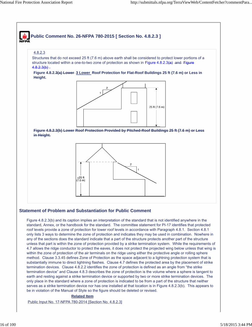
Structures that do not exceed 25 ft (7.6 m) above earth shall be considered to protect lower portions of astructure located within a one-to-two zone of protection as shown in Figure 4.8.2.3(a) and Figure4.8.2.3(b) .
Figure 4.8.2.3(a) Lower 3 Lower Roof Protection for Flat-Roof Buildings 25 ft (7.6 m) or Less inHeight.
Figure 4.8.2.3(b) Lower Roof Protection Provided by Pitched-Roof Buildings 25 ft (7.6 m) or Lessin Height.
Statement of Problem and Substantiation for Public Comment
Figure 4.8.2.3(b) and its caption implies an interpretation of the standard that is not identified anywhere in the standard, Annex, or the handbook for the standard. The committee statement for PI-17 identifies that protected roof levels provide a zone of protection for lower roof levels in accordance with Paragraph 4.8.1. Section 4.8.1 only lists 3 ways to determine the zone of protection and indicates they may be used in combination. Nowhere in any of the sections does the standard indicate that a part of the structure protects another part of the structure unless that part is within the zone of protection provided by a strike termination system. While the requirements of 4.7 allows the ridge conductor to protect the eaves, it does not protect the projected wing below unless that wing is within the zone of protection of the air terminals on the ridge using either the protective angle or rolling sphere method. Clause 3.3.45 defines Zone of Protection as the space adjacent to a lightning protection system that is substantially immune to direct lightning flashes. Clause 4.7 defines the protected area by the placement of strike termination devices. Clause 4.8.2.2 identifies the zone of protection is defined as an angle from “the strike termination device” and Clause 4.8.3 describes the zone of protection is the volume where a sphere is tangent to earth and resting against a strike termination device or supported by two or more strike termination devices. The only place in the standard where a zone of protection is indicated to be from a part of the structure that neither serves as a strike termination device nor has one installed at that location is in Figure 4.8.2.3(b). This appears to be in violation of the Manual of Style so the figure should be deleted or revised.
Related Item
Public Input No. 17-NFPA 780-2014 [Section No. 4.8.2.3]
National Fire Protection Association Report http://submittals.nfpa.org/TerraViewWeb/ContentFetcher?commentPara...
16 of 100 5/18/2015 3:44 PM
Submitter Information Verification
Submitter Full Name: MITCHELL GUTHRIE
Organization: ENGINEERING CONSULTANT
Street Address:
City:
State:
Zip:
Submittal Date: Wed Apr 29 22:59:01 EDT 2015
National Fire Protection Association Report http://submittals.nfpa.org/TerraViewWeb/ContentFetcher?commentPara...
17 of 100 5/18/2015 3:44 PM

Public Comment No. 55-NFPA 780-2015 [ Section No. 4.13.1.1 ]
4.13.1.1
Each down conductor shall terminate into be terminated by a grounding system using one of the followingmethods:
(1) A grounding electrode dedicated to the lightning protection system
(2) A grounding electrode system composed of a ground ring electrode as described in 4.13.4
(3) A grounding system composed of a ground ring electrode as described in 4.13.4 , facilityground mesh
(4) It shall be permi ed that Methods (3) and (4) be supplemented by multiple grounding electrodes.
Statement of Problem and Substantiation for Public Comment
The change made to 4.13.1.1 had the unintended (I hope) result of undoing the change made in the 2014 Edition which allowed the use of a mesh-type ground grid installed for a facility to also be used to ground the lightning protection system. This proposal will correct the oversight by adding a fourth method to retain the ground mesh as an approved grounding method.
Related Item
Public Input No. 134-NFPA 780-2014 [Section No. 4.13.1.1]
First Revision No. 81-NFPA 780-2014 [Section No. 4.13.1.1]
Submitter Information Verification
Submitter Full Name: MITCHELL GUTHRIE
Organization: ENGINEERING CONSULTANT
Street Address:
City:
State:
Zip:
Submittal Date: Sat May 02 20:29:33 EDT 2015
National Fire Protection Association Report http://submittals.nfpa.org/TerraViewWeb/ContentFetcher?commentPara...
18 of 100 5/18/2015 3:44 PM

Public Comment No. 100-NFPA 780-2015 [ New Section after 4.13.1.6 ]
4.13.1.1 A Really Bad Idea
4.13.1.7 Grounding electrodes that will be covered or concealed by the building, structure or finish shallbe
accessible.
Statement of Problem and Substantiation for Public Comment
This would be an extremely onerous requirement since ground electrode are required to be buried except where they are installed on solid bed rock. The terms used in the requirement are vague and nebulous. What Constitutes a "finish"? Also, what does "accessible" mean? This requirement would add unnecessary additional cost to the lightning protection system without adding any functional value. There are frequent installation where fill is being used and finish grade is several stories above where the ground electrode is installed. How would cost effective access to that electrode be provided?
Related Item
Committee Input No. 86-NFPA 780-2014 [New Section after 4.13.1.6]
Submitter Information Verification
Submitter Full Name: STEPHEN HUMENIUK
Organization: WARREN LIGHTNING ROD COMPANY
Affilliation: ULPA
Street Address:
City:
State:
Zip:
Submittal Date: Fri May 15 16:44:49 EDT 2015
National Fire Protection Association Report http://submittals.nfpa.org/TerraViewWeb/ContentFetcher?commentPara...
19 of 100 5/18/2015 3:44 PM

Public Comment No. 57-NFPA 780-2015 [ New Section after 4.13.1.6 ]
4.13.1.7
The grounding electrode system shall have an access point near grade level forfuture testing of a representative grounding electrode or the complete groundingsystem. The access point can either be located at a grounding electrode or a lowpoint in the down conductor. Grounding electrode systems or devices coveredonly by bare earth shall be considered accessible without any addition for testing.
Statement of Problem and Substantiation for Public Comment
CI # 86 for comment by industryExpands on proposal to allow test points and provides clarificaitons
Related Item
Committee Input No. 86-NFPA 780-2014 [New Section after 4.13.1.6]
Submitter Information Verification
Submitter Full Name: HAROLD VANSICKLE
Organization: LIGHTNING PROTECTION INSTITUTE
Street Address:
City:
State:
Zip:
Submittal Date: Thu May 07 10:36:15 EDT 2015
National Fire Protection Association Report http://submittals.nfpa.org/TerraViewWeb/ContentFetcher?commentPara...
20 of 100 5/18/2015 3:44 PM
Public Comment No. 65-NFPA 780-2015 [ New Section after 4.13.1.6 ]
4.13.1.7 Grounding electrodes that will be covered or concealed by the building, structure orfinish shall be accessible.
Statement of Problem and Substantiation for Public Comment
I support this proposed change. Lightning protection system components need to be accessible for inspection. Re-inspection of existing systems is not possible if the grounding electrodes are not accessible. We have tried to evaluate a number of existing LPS on older buildings where the grounding electrodes are not accessible.
Related Item
Committee Input No. 86-NFPA 780-2014 [New Section after 4.13.1.6]
Submitter Information Verification
Submitter Full Name: CARL JOHNSON II
Organization: AVCON INC
Affilliation: none
Street Address:
City:
State:
Zip:
Submittal Date: Sat May 09 12:26:17 EDT 2015
National Fire Protection Association Report http://submittals.nfpa.org/TerraViewWeb/ContentFetcher?commentPara...
21 of 100 5/18/2015 3:44 PM

Public Comment No. 30-NFPA 780-2015 [ Section No. 4.13.8.3.2 ]
4.13.8.3.2
Ground rods in accordance with 4.13.2, ground ring electrodes in accordance with 4.13.4, radials inaccordance with 4.13.5, or ground plate electrodes in accordance with 4.13.6 shall be installed below thestructure in compacted earth and made tight earth tight against the electrode.
Statement of Problem and Substantiation for Public Comment
The wording "and made tight" indicates once the ground device is installed the earth is then moved into position. This doesn't make sense, but neither does using a term like driven into "undisturbed earth, because in this case we are talking about earth under the structure that was probably disturbed and reconfigured during the construction process. This seems the best resolution on the intent.
Related Item
First Revision No. 145-NFPA 780-2014 [Sections 4.18.4.1, 4.18.4.2]
Submitter Information Verification
Submitter Full Name: HAROLD VANSICKLE
Organization: LIGHTNING PROTECTION INSTITUTE
Street Address:
City:
State:
Zip:
Submittal Date: Thu Apr 30 11:19:50 EDT 2015
National Fire Protection Association Report http://submittals.nfpa.org/TerraViewWeb/ContentFetcher?commentPara...
22 of 100 5/18/2015 3:44 PM

Public Comment No. 58-NFPA 780-2015 [ New Section after 4.16.2 ]
4.16.3
4.16.3 Long, Horizontal Metal Bodies on Roofs. Long horizontal grounded metal bodies on roofsshall be bonded in accordance with 4.16.3.1 through 4.16.3.3.
4.16.3.1 Grounded and ungrounded metal bodies on roofs exceeding 60 ft. in horizontal length shall bebonded to the lightning protection system as near as practicable to their extremities unless inherentlybonded through construction at those locations.
4.16.3.2 Horizontal grounded metal bodies that are parallel to a main lightning conductor and that arewithin the bonding distance calculated in 4.16.2.4 or 4.16.2.5 shall be bonded to the main conductor atintervals averaging not more than 100 ft. (30 m) along the main conductor unless inherently bonded throughconstruction at those locations.
4.16.3.3 Horizontal grounded metal bodies that cross a main conductor shall be bonded to the mainconductor where they cross the conductor unless inherently bonded through construction at that location.
Statement of Problem and Substantiation for Public Comment
CI # 93 for industry commentThere are ungrounded metal bodies on roofs or at roof level, exceeding 60 feet in length, that are not a hazard. They are under the zone of protection, beyond the calculated bonding distance, and do not serve as a path to alternate grounded systems. Like the gutter on the back side of my house. Bonding items like this would waste material and labor for no real purpose.
Related Item
Committee Input No. 93-NFPA 780-2014 [New Section after 4.16.2.5.2]
Submitter Information Verification
Submitter Full Name: HAROLD VANSICKLE
Organization: LIGHTNING PROTECTION INSTITUTE
Street Address:
City:
State:
Zip:
Submittal Date: Thu May 07 10:46:02 EDT 2015
National Fire Protection Association Report http://submittals.nfpa.org/TerraViewWeb/ContentFetcher?commentPara...
23 of 100 5/18/2015 3:44 PM
Public Comment No. 64-NFPA 780-2015 [ New Section after 4.16.2.5.2 ]
Committee Input No. 93-NFPA 780-2014 [ New Section after 4.16.2.5.2 ]
4.16.3 Long, Horizontal Metal Bodies on Roofs. Long, horizontal metal bodies on roofsshall be bonded
in accordance with 4.16.3.1 through 4.16.3.3 .
4.16.3.1 Grounded and ungrounded metal bodies on roofs exceeding 60 ft (18 m) inhorizontal length shall
be bonded to the lightning protection system as near as practicable to their extremities unlessinherently
bonded through construction at those locations.
4.16.3.2 Horizontal metal bodies that are parallel to a main lightning conductor and that arewithin the
bonding distance calculated in 4.16.2.4 or 4.16.2.5 shall be bonded to the main conductor atintervals
averaging not more than 100 ft (30 m) along the main conductor unless inherently bondedthrough
construction at those locations.
4.16.3.3. Horizontal metal bodies that cross a main conductor shall be bonded to the mainconductor
where they cross the conductor unless inherently bonded through construction at that location.
Statement of Problem and Substantiation for Public Comment
I support Committee Input No. 93. The proper bonding of long horizontal metallic items on a roof is an important feature of a quality LPS.
Related Item
Committee Input No. 93-NFPA 780-2014 [New Section after 4.16.2.5.2]
Submitter Information Verification
Submitter Full Name: CARL JOHNSON II
Organization: AVCON INC
Affilliation: none
Street Address:
City:
State:
Zip:
Submittal Date: Sat May 09 12:20:56 EDT 2015
National Fire Protection Association Report http://submittals.nfpa.org/TerraViewWeb/ContentFetcher?commentPara...
24 of 100 5/18/2015 3:44 PM

Public Comment No. 101-NFPA 780-2015 [ New Section after 4.16.3.1 ]
4.16.3 Long, Horizontal Metal Bodies on Roofs. Long, horizontal metal bodies on roofsshall be bonded
in accordance with 4.16.3.1 through 4.16.3.3 .
4.16.3.1 Grounded and ungrounded metal bodies on roofs exceeding 60 ft (18 m) inhorizontal length shall
be bonded to the lightning protection system as near as practicable to their extremities unlessinherently
bonded through construction at those locations.
4.16.3.2 Horizontal metal bodies that are parallel to a main lightning conductor and that arewithin the
bonding distance calculated in 4.16.2.4 or 4.16.2.5 shall be bonded to the main conductor atintervals
averaging not more than 100 ft (30 m) along the main conductor unless inherently bondedthrough
construction at those locations.
4.16.3.3. Horizontal metal bodies that cross a main conductor shall be bonded to the mainconductor
where they cross the conductor unless inherently bonded through construction at that location.
Statement of Problem and Substantiation for Public Comment
The current requirements of the standard do not differentiate between vertical or horizontal metal bodies and are applicable to both. As written, further substantiation would need to be provided to justify the additional requirements.This would be best considered in a future revision cycle.
Related Item
Committee Input No. 93-NFPA 780-2014 [New Section after 4.16.2.5.2]
Submitter Information Verification
Submitter Full Name: STEPHEN HUMENIUK
Organization: WARREN LIGHTNING ROD COMPANY
Affilliation: ULPA
Street Address:
City:
State:
Zip:
Submittal Date: Fri May 15 17:03:52 EDT 2015
National Fire Protection Association Report http://submittals.nfpa.org/TerraViewWeb/ContentFetcher?commentPara...
25 of 100 5/18/2015 3:44 PM
Public Comment No. 28-NFPA 780-2015 [ Section No. 4.16.3.3.2 ]
4.16.3.3.2
The bonding connection shall be permitted to be made from the lightning protection system to theungrounded metal body and from the isolated the ungrounded metal body to the grounded metal body.
Statement of Problem and Substantiation for Public Comment
4.16.3.3.2 The bonding connection shall be permitted to be made from the lightning protection system to the ungrounded metal body and from the "isolated" ungrounded metal body to the grounded metal body. The last use of term "isolated" was not changed to "ungrounded". This was in the PI, but not the FR.
Related Item
First Revision No. 92-NFPA 780-2014 [Section No. 4.16.3]
Submitter Information Verification
Submitter Full Name: HAROLD VANSICKLE
Organization: LIGHTNING PROTECTION INSTITUTE
Street Address:
City:
State:
Zip:
Submittal Date: Thu Apr 30 11:00:59 EDT 2015
National Fire Protection Association Report http://submittals.nfpa.org/TerraViewWeb/ContentFetcher?commentPara...
26 of 100 5/18/2015 3:44 PM

Public Comment No. 29-NFPA 780-2015 [ Section No. 4.16.4 ]
4.16.4 Materials.
Conductors used for the bonding of grounded metal bodies or isolated or ungrounded metal bodiesrequiring connection to the lightning protection system shall be sized in accordance with bonding conductorrequirements in Table 4.1.1.1.1 and Table 4.1.1.1.2.
Statement of Problem and Substantiation for Public Comment
use of the term "isolated" was removed from all sections of the document where the term "ungrounded" would better define the metal body in question - with the exception of this paragraph which was missed in the original FR set.
Related Item
First Revision No. 92-NFPA 780-2014 [Section No. 4.16.3]
Submitter Information Verification
Submitter Full Name: HAROLD VANSICKLE
Organization: LIGHTNING PROTECTION INSTITUTE
Street Address:
City:
State:
Zip:
Submittal Date: Thu Apr 30 11:07:58 EDT 2015
National Fire Protection Association Report http://submittals.nfpa.org/TerraViewWeb/ContentFetcher?commentPara...
27 of 100 5/18/2015 3:44 PM
Public Comment No. 103-NFPA 780-2015 [ New Section after 4.20.4 ]
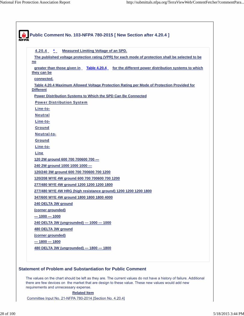
4.20.4 * Measured Limiting Voltage of an SPD.
The published voltage protection rating (VPR) for each mode of protection shall be selected to beno
greater than those given in Table 4.20.4 for the different power distribution systems to whichthey can be
connected.
Table 4.20.4 Maximum Allowed Voltage Protection Rating per Mode of Protection Provided forDifferent
Power Distribution Systems to Which the SPD Can Be Connected
Power Distribution System
Line-to-
Neutral
Line-to-
Ground
Neutral-to-
Ground
Line-to-
Line
120 2W ground 600 700 700600 700 —
240 2W ground 1000 1000 1000 —
120/240 3W ground 600 700 700600 700 1200
120/208 WYE 4W ground 600 700 700600 700 1200
277/480 WYE 4W ground 1200 1200 1200 1800
277/480 WYE 4W HRG (high resistance ground) 1200 1200 1200 1800
347/600 WYE 4W ground 1800 1800 1800 4000
240 DELTA 3W ground
(corner grounded)
— 1000 — 1000
240 DELTA 3W (ungrounded) — 1000 — 1000
480 DELTA 3W ground
(corner grounded)
— 1800 — 1800
480 DELTA 3W (ungrounded) — 1800 — 1800
Statement of Problem and Substantiation for Public Comment
The values on the chart should be left as they are. The current values do not have a history of failure. Additional there are few devices on the market that are design to these value. These new values would add new requirements and unnecessary expense.
Related Item
Committee Input No. 21-NFPA 780-2014 [Section No. 4.20.4]
National Fire Protection Association Report http://submittals.nfpa.org/TerraViewWeb/ContentFetcher?commentPara...
28 of 100 5/18/2015 3:44 PM

Submitter Information Verification
Submitter Full Name: STEPHEN HUMENIUK
Organization: WARREN LIGHTNING ROD COMPANY
Affilliation: ULPA
Street Address:
City:
State:
Zip:
Submittal Date: Fri May 15 17:32:26 EDT 2015
National Fire Protection Association Report http://submittals.nfpa.org/TerraViewWeb/ContentFetcher?commentPara...
29 of 100 5/18/2015 3:44 PM

Public Comment No. 104-NFPA 780-2015 [ Section No. 5.3 ]
5.3 Grain-, Coal-, and Coke-Handling and -Processing Structures.
Provisions shall be made for
F acilities that Handle or Process Combustible or Explosive Dust.5.3.1 Provisions shall be made for grain elevators and other food processing facilities to prevent ignition
of
combustible dust in accordance with this standard and NFPA 61 Standard for the Prevention of Firesand
Dust Explosions in Agricultural and Food Processing Facilities .
5.3.2 Provisions shall be made for coal and coke processing faciliries to prevent ignition of combustible
dust in accordance with this standard and NFPA 122 Standard for Fire Prevention and Control in
Metal/Nonmetal Mining and Metal Mineral Processing Facilities .
5.3.3 Provisions shall be made for the settling and rising of
wood frame elevators as grain, coal, and coke are loaded and
unloaded.
5.3.4 Provisions shall be made for wood working facilities to prevent ignition of combustible dust in
accordance with this standard and NFPA 664 Standard for the Prevention of Fires and Explosions inWood
Processing and Woodworking Facilities .
Statement of Problem and Substantiation for Public Comment
The text covers additional facilities' that are susceptible to fire and explosion from a lightning strike.
Related Item
Committee Input No. 64-NFPA 780-2014 [Section No. 5.3]
Submitter Information Verification
Submitter Full Name: STEPHEN HUMENIUK
Organization: WARREN LIGHTNING ROD COMPANY
Affilliation: ULPA
Street Address:
City:
State:
Zip:
Submittal Date: Fri May 15 17:39:06 EDT 2015
National Fire Protection Association Report http://submittals.nfpa.org/TerraViewWeb/ContentFetcher?commentPara...
30 of 100 5/18/2015 3:44 PM

Public Comment No. 31-NFPA 780-2015 [ Section No. 5.9.4.2 ]
5.9.4.2
A ground grid shall be installed under the fabric structure in accordance with Annex G - Section G .1.1.3.
Statement of Problem and Substantiation for Public Comment
5.9.4.2 "A ground grid shall be installed under the fabric structure." A reference to what is considered a ground grid is needed. The reference in the 2014 document is in Annex G.1.1.3. I am not sure, however, if we can reference Annex material in the requirements or the information in G.1.1.3 might need to be moved up to this section of Chapter 5.
Related Item
First Revision No. 65-NFPA 780-2014 [New Section after 5.8.7]
Submitter Information Verification
Submitter Full Name: HAROLD VANSICKLE
Organization: LIGHTNING PROTECTION INSTITUTE
Street Address:
City:
State:
Zip:
Submittal Date: Thu Apr 30 11:33:37 EDT 2015
National Fire Protection Association Report http://submittals.nfpa.org/TerraViewWeb/ContentFetcher?commentPara...
31 of 100 5/18/2015 3:44 PM

Public Comment No. 32-NFPA 780-2015 [ Section No. 6.1 ]
6.1 General.
A smoke or vent stack as shown in Figure 6.1 shall be classified as heavy duty if the cross-sectional area
of the flue is greater than 500 in.2 (0.3 m2) and the height is greater than 75 ft (23 m), above groundlevel grade level .
Figure 6.1 Heavy-Duty Stack.
Statement of Problem and Substantiation for Public Comment
The term "ground level" could be interpreted to mean grade level, ground floor level, or the level of the highest ground loop - possibly a roof circuit. Reference to the illustration of a free-standing stack would indicate the height is determined above grade.
Related Item
First Revision No. 149-NFPA 780-2014 [Section No. 6.1]
Submitter Information Verification
Submitter Full Name: HAROLD VANSICKLE
National Fire Protection Association Report http://submittals.nfpa.org/TerraViewWeb/ContentFetcher?commentPara...
32 of 100 5/18/2015 3:44 PM
Organization: LIGHTNING PROTECTION INSTITUTE
Street Address:
City:
State:
Zip:
Submittal Date: Thu Apr 30 12:39:23 EDT 2015
National Fire Protection Association Report http://submittals.nfpa.org/TerraViewWeb/ContentFetcher?commentPara...
33 of 100 5/18/2015 3:44 PM

Public Comment No. 35-NFPA 780-2015 [ Section No. 7.2.3 ]
7.2.3 Lightning Protection System.
Protection of structures not considered inherently protected as per Structures not inherently protected per7.2.2 shall be protected in provided with protection in accordance with the requirements of Section 7.3except as modified by requirements for modified for specific types of structures (see Section 7.4).
Statement of Problem and Substantiation for Public Comment
The sentence is confusing as presented.
Related Item
First Revision No. 146-NFPA 780-2014 [Chapter 7]
Submitter Information Verification
Submitter Full Name: HAROLD VANSICKLE
Organization: LIGHTNING PROTECTION INSTITUTE
Street Address:
City:
State:
Zip:
Submittal Date: Thu Apr 30 15:29:20 EDT 2015
National Fire Protection Association Report http://submittals.nfpa.org/TerraViewWeb/ContentFetcher?commentPara...
34 of 100 5/18/2015 3:44 PM

Public Comment No. 36-NFPA 780-2015 [ Section No. 7.3.3.2 ]
7.3.3.2 *
The placement of strike termination devices shall take into consideration that it is possible for sparks ordamaging impact to occur at the striking point attachment point .
Statement of Problem and Substantiation for Public Comment
Matches existing text throughout the document.
Related Item
First Revision No. 146-NFPA 780-2014 [Chapter 7]
Submitter Information Verification
Submitter Full Name: HAROLD VANSICKLE
Organization: LIGHTNING PROTECTION INSTITUTE
Street Address:
City:
State:
Zip:
Submittal Date: Thu Apr 30 15:34:10 EDT 2015
National Fire Protection Association Report http://submittals.nfpa.org/TerraViewWeb/ContentFetcher?commentPara...
35 of 100 5/18/2015 3:44 PM

Public Comment No. 85-NFPA 780-2015 [ Section No. 7.3.3.2 ]
7.3.3.2 *
The placement of strike termination devices shall take into consideration that it is possible for sparks ordamaging impact to occur at the striking the attachment point.
Statement of Problem and Substantiation for Public Comment
Editorial. Attachment point is the preferred term in the standard.
Related Item
Public Input No. 218-NFPA 780-2014 [Sections 7.1, 7.2, 7.3]
First Revision No. 146-NFPA 780-2014 [Chapter 7]
Submitter Information Verification
Submitter Full Name: MITCHELL GUTHRIE
Organization: ENGINEERING CONSULTANT
Street Address:
City:
State:
Zip:
Submittal Date: Fri May 15 08:06:31 EDT 2015
National Fire Protection Association Report http://submittals.nfpa.org/TerraViewWeb/ContentFetcher?commentPara...
36 of 100 5/18/2015 3:44 PM

Public Comment No. 37-NFPA 780-2015 [ Section No. 7.3.4.3 ]
7.3.4.3
Where it is not practicable to install down conductors external to the hazardous location it shall be ensuredthat the auto-ignition temperature for the gas or vapor causing the hazardous environment is not exceeded.
Statement of Problem and Substantiation for Public Comment
It is not practical to include this requirement without identifying for the user a method to calculate the temperature of the down conductor for comparison to the ignition temperature of the hazardous location. If the temperature can not be quantified based on design or material variability, then open down conductors should not be used in this environment. They should be run in hazardous area qualified enclosures.
Related Item
First Revision No. 146-NFPA 780-2014 [Chapter 7]
Submitter Information Verification
Submitter Full Name: HAROLD VANSICKLE
Organization: LIGHTNING PROTECTION INSTITUTE
Street Address:
City:
State:
Zip:
Submittal Date: Thu Apr 30 15:40:31 EDT 2015
National Fire Protection Association Report http://submittals.nfpa.org/TerraViewWeb/ContentFetcher?commentPara...
37 of 100 5/18/2015 3:44 PM

Public Comment No. 59-NFPA 780-2015 [ Section No. 7.3.7 ]
7.3.7 * Grounding.
A ground ring electrode or ground loop conductor supplemented by grounding electrodes as identified in4.13.2 through 4.13.7 shall be provided for structures containing flammable vapors, flammable gases, orliquids that can give off flammable vapors.
Move this paragraph to Chapter 5 or be more specific that this particular paragraph doesn't apply tostorage tanks. Storage tank grounding is handled lower in this Chapter and this could be viewed by readeras confusing or in conflict with another paragraph within this same chapter.
Statement of Problem and Substantiation for Public Comment
Because grounding for tanks is addressed within this same chapter. Having it twice without direction could be confusing.
Related Item
First Revision No. 146-NFPA 780-2014 [Chapter 7]
Submitter Information Verification
Submitter Full Name: MORRIS KLINE
Organization: LIGHTNING MASTER CORPORATION
Street Address:
City:
State:
Zip:
Submittal Date: Fri May 08 09:26:22 EDT 2015
National Fire Protection Association Report http://submittals.nfpa.org/TerraViewWeb/ContentFetcher?commentPara...
38 of 100 5/18/2015 3:44 PM
Public Comment No. 38-NFPA 780-2015 [ Section No. 7.4.1.1 ]
7.4.1.1
Structures containing hazardous (classified) locations used in nonstorage applications shall comply with therequirements of Section 7. 3 unless justified by a lightning risk assessment 2 .
Statement of Problem and Substantiation for Public Comment
Non-storage structures that include hazardous areas are typically processing structures that need protection.
Related Item
First Revision No. 146-NFPA 780-2014 [Chapter 7]
Submitter Information Verification
Submitter Full Name: HAROLD VANSICKLE
Organization: LIGHTNING PROTECTION INSTITUTE
Street Address:
City:
State:
Zip:
Submittal Date: Thu Apr 30 15:57:29 EDT 2015
National Fire Protection Association Report http://submittals.nfpa.org/TerraViewWeb/ContentFetcher?commentPara...
39 of 100 5/18/2015 3:44 PM

Public Comment No. 39-NFPA 780-2015 [ Section No. 7.4.1.2 ]
7.4.1.2 *
For structures in which the hazardous (classified) location exists in only one part of the structure, it shall bepermitted for a risk assessment to utilize the lightning protection zone (LPZ) concept in accordance withIEC 62305-2, Protection Against Lightning—Part 2: Risk Management .
Statement of Problem and Substantiation for Public Comment
Structures that include hazardous locations should have lightning protection.
Related Item
First Revision No. 146-NFPA 780-2014 [Chapter 7]
Submitter Information Verification
Submitter Full Name: HAROLD VANSICKLE
Organization: LIGHTNING PROTECTION INSTITUTE
Street Address:
City:
State:
Zip:
Submittal Date: Thu Apr 30 16:14:15 EDT 2015
National Fire Protection Association Report http://submittals.nfpa.org/TerraViewWeb/ContentFetcher?commentPara...
40 of 100 5/18/2015 3:44 PM
Public Comment No. 40-NFPA 780-2015 [ Section No. 7.4.2.1 ]
7.4.2.1
It shall be permitted for the authority having jurisdiction to waive the requirements of this chapter for sealedSealed metallic tanks, vessels, and process equipment that contain flammable or combustible liquids orflammable gases under pressure are considered to be inherently self-protecting provided the vessel isgrounded (either inherently or by external means) and the walls of the vessel are greater than 3⁄16 in. (4.8mm) thick to prevent puncture by a direct strike in accordance with 7 .2.2.
Statement of Problem and Substantiation for Public Comment
The AHJ can always waive requirements - this does not need to be included here. This statement is already included in 7.2.2, but can be re-emphasized here for this type vessel.
Related Item
First Revision No. 146-NFPA 780-2014 [Chapter 7]
Submitter Information Verification
Submitter Full Name: HAROLD VANSICKLE
Organization: LIGHTNING PROTECTION INSTITUTE
Street Address:
City:
State:
Zip:
Submittal Date: Thu Apr 30 16:19:35 EDT 2015
National Fire Protection Association Report http://submittals.nfpa.org/TerraViewWeb/ContentFetcher?commentPara...
41 of 100 5/18/2015 3:44 PM
Public Comment No. 53-NFPA 780-2015 [ New Section after 7.4.2.2 ]
Add new 7.4.2.2* as follows and renumber existing 7.4.2.2 as 7.4.2.3.
The decision to waive the requirements for protection of storage tanks under pressure shall take intoconsideration the temperature rise of the internal surface of lightning attachment points and the ignitiontemperature of the contents of the tank.
Statement of Problem and Substantiation for Public Comment
7.4.2.1 addresses the issue of burn-through but does not address the issue of hot spots on internal surfaces resulting from the arc root temperature at the attachment point. The proposed new text addresses this issue.
Related Public Comments for This Document
Related Comment Relationship
Public Comment No. 95-NFPA 780-2015 [New Section after A.7.4.1.2]
Public Comment No. 97-NFPA 780-2015 [Section No. O.1.2.8]
Related Item
First Revision No. 146-NFPA 780-2014 [Chapter 7]
Submitter Information Verification
Submitter Full Name: MITCHELL GUTHRIE
Organization: ENGINEERING CONSULTANT
Street Address:
City:
State:
Zip:
Submittal Date: Thu Apr 30 18:01:14 EDT 2015
National Fire Protection Association Report http://submittals.nfpa.org/TerraViewWeb/ContentFetcher?commentPara...
42 of 100 5/18/2015 3:44 PM
Public Comment No. 41-NFPA 780-2015 [ Section No. 7.4.3.1 ]
7.4.3. 1 5 * Fixed Roof Tanks (Metallic) and Tanks with Internal Floating Roofs.
Sliding or fixed contact conductors shall not be mandatory for lightning protection for fixed roof and internalfloating roof tanks.
Statement of Problem and Substantiation for Public Comment
This section is misplaced in the document. You should first define what sliding and fixed contacts are, then it makes sense that you don't need these on a fixed roof tank. I've shown moving it back to 7.4.3.5 to put it before Metallic tanks with nonmetallic roofs, because in reality everything moves up one number if it is deleted as 7.4.3.1.
Related Item
First Revision No. 146-NFPA 780-2014 [Chapter 7]
Submitter Information Verification
Submitter Full Name: HAROLD VANSICKLE
Organization: LIGHTNING PROTECTION INSTITUTE
Street Address:
City:
State:
Zip:
Submittal Date: Thu Apr 30 16:30:43 EDT 2015
National Fire Protection Association Report http://submittals.nfpa.org/TerraViewWeb/ContentFetcher?commentPara...
43 of 100 5/18/2015 3:44 PM

Public Comment No. 43-NFPA 780-2015 [ Section No. 7.4.3.2.2.1 ]
7.4.3.2.2.1
The shunt shall have as short and direct a path as possible from the conductive floating roof to the tankshell.
(A)
The shunts shall be of the minimum length necessary to permit the function of the floating roof assembly.
(B)
The shunts shall be of the minimum length necessary to remain in contact with the shell during the fullhorizontal and vertical design movement of the floating roof.
Statement of Problem and Substantiation for Public Comment
Paragraph 7.4.3.2.2.7 describes shunt length, as does 7.4.3.2.2.1. They should be combined.
Related Item
First Revision No. 146-NFPA 780-2014 [Chapter 7]
Submitter Information Verification
Submitter Full Name: HAROLD VANSICKLE
Organization: LIGHTNING PROTECTION INSTITUTE
Street Address:
City:
State:
Zip:
Submittal Date: Thu Apr 30 16:47:37 EDT 2015
National Fire Protection Association Report http://submittals.nfpa.org/TerraViewWeb/ContentFetcher?commentPara...
44 of 100 5/18/2015 3:44 PM

Public Comment No. 3-NFPA 780-2015 [ Section No. 7.4.3.2.2.3 ]
7.4.3.2.2.3
Above-deck shunts shall be removed when retrofitting existing tanks with submerged shunts.
Add caution note "consult with seal manufacturer prior to removal of above-deck shunts". Some sealmanufacturers could be using shunts as part of their seal system.
Statement of Problem and Substantiation for Public Comment
Because seal manufactures have be providing shunts for static electricity control, they may need to be consulted prior to shunt removal.
Related Item
First Revision No. 146-NFPA 780-2014 [Chapter 7]
Submitter Information Verification
Submitter Full Name: Morris Kline
Organization: Lightning Master Corporation
Street Address:
City:
State:
Zip:
Submittal Date: Tue Feb 24 08:17:21 EST 2015
National Fire Protection Association Report http://submittals.nfpa.org/TerraViewWeb/ContentFetcher?commentPara...
45 of 100 5/18/2015 3:44 PM

Public Comment No. 42-NFPA 780-2015 [ Section No. 7.4.3.2.2.3 ]
7.4.3.2.2. 3 8
Above-deck shunts shall be removed when retrofitting existing tanks with submerged shunts.
Statement of Problem and Substantiation for Public Comment
This paragraph is out of place. The other paragraphs describe the shunt, but this paragraph requires removal of above deck shunts. it doesn't fit here.
Related Item
First Revision No. 146-NFPA 780-2014 [Chapter 7]
Submitter Information Verification
Submitter Full Name: HAROLD VANSICKLE
Organization: LIGHTNING PROTECTION INSTITUTE
Street Address:
City:
State:
Zip:
Submittal Date: Thu Apr 30 16:42:52 EDT 2015
National Fire Protection Association Report http://submittals.nfpa.org/TerraViewWeb/ContentFetcher?commentPara...
46 of 100 5/18/2015 3:44 PM

Public Comment No. 44-NFPA 780-2015 [ Section No. 7.4.3.2.2.7 ]
7.4.3.2.2.7 Shunt Length.
(A)
The shunts shall be of the minimum length necessary to permit the function of the floating roof assembly.
(B)
The shunts shall be of the minimum length necessary to remain in contact with the shell during the fullhorizontal and vertical design movement of the floating roof.
Statement of Problem and Substantiation for Public Comment
Moved to 7.4.3.2.2.1
Related Item
First Revision No. 146-NFPA 780-2014 [Chapter 7]
Submitter Information Verification
Submitter Full Name: HAROLD VANSICKLE
Organization: LIGHTNING PROTECTION INSTITUTE
Street Address:
City:
State:
Zip:
Submittal Date: Thu Apr 30 16:50:58 EDT 2015
National Fire Protection Association Report http://submittals.nfpa.org/TerraViewWeb/ContentFetcher?commentPara...
47 of 100 5/18/2015 3:44 PM
Public Comment No. 45-NFPA 780-2015 [ Section No. 7.4.3.2.2.8 ]
7.4.3.2.2.8 *
The shunts and terminations shall be of sufficient flexibility, cross-sectional area, and corrosion resistanceto maximize service life.
Statement of Problem and Substantiation for Public Comment
This information is already in 7.4.3.2.2.4 & 7.4.3.2.2.5.
Related Item
First Revision No. 146-NFPA 780-2014 [Chapter 7]
Submitter Information Verification
Submitter Full Name: HAROLD VANSICKLE
Organization: LIGHTNING PROTECTION INSTITUTE
Street Address:
City:
State:
Zip:
Submittal Date: Thu Apr 30 16:53:39 EDT 2015
National Fire Protection Association Report http://submittals.nfpa.org/TerraViewWeb/ContentFetcher?commentPara...
48 of 100 5/18/2015 3:44 PM
Public Comment No. 46-NFPA 780-2015 [ Section No. 7.4.3.3.1 ]
7.4.3.3.1
The tank’s floating roof shall be bonded to the tank shell by direct electrical connection such as a bypasswith a Class I main size bypass conductor.
Statement of Problem and Substantiation for Public Comment
The size of the bypass conductor needs to be defined.
Related Item
First Revision No. 146-NFPA 780-2014 [Chapter 7]
Submitter Information Verification
Submitter Full Name: HAROLD VANSICKLE
Organization: LIGHTNING PROTECTION INSTITUTE
Street Address:
City:
State:
Zip:
Submittal Date: Thu Apr 30 16:56:13 EDT 2015
National Fire Protection Association Report http://submittals.nfpa.org/TerraViewWeb/ContentFetcher?commentPara...
49 of 100 5/18/2015 3:44 PM

Public Comment No. 47-NFPA 780-2015 [ Section No. 7.4.3.3.4 ]
7.4.3.3.4
A minimum of two bypass conductors shall be evenly spaced not more than every conductors evenlyspaced on the perimeter shall be provded for all tanks, and an additional bypass conductor shall beprovided for every 100 ft (30 m) around the tank circumference.
Statement of Problem and Substantiation for Public Comment
The intent of the current wording is not clear.
Related Item
First Revision No. 146-NFPA 780-2014 [Chapter 7]
Submitter Information Verification
Submitter Full Name: HAROLD VANSICKLE
Organization: LIGHTNING PROTECTION INSTITUTE
Street Address:
City:
State:
Zip:
Submittal Date: Thu Apr 30 17:00:11 EDT 2015
National Fire Protection Association Report http://submittals.nfpa.org/TerraViewWeb/ContentFetcher?commentPara...
50 of 100 5/18/2015 3:44 PM

Public Comment No. 48-NFPA 780-2015 [ Section No. 7.4.3.3.5.1 ]
7.4.3.3.5.1
A minimum of one bypass A Class I main size bypass conductor shall be installed along and bonded to therolling ladder, if installed .
Statement of Problem and Substantiation for Public Comment
Clarifies the intent this is a current carrying part of the system.
Related Item
First Revision No. 146-NFPA 780-2014 [Chapter 7]
Submitter Information Verification
Submitter Full Name: HAROLD VANSICKLE
Organization: LIGHTNING PROTECTION INSTITUTE
Street Address:
City:
State:
Zip:
Submittal Date: Thu Apr 30 17:11:56 EDT 2015
National Fire Protection Association Report http://submittals.nfpa.org/TerraViewWeb/ContentFetcher?commentPara...
51 of 100 5/18/2015 3:44 PM

Public Comment No. 60-NFPA 780-2015 [ Section No. 7.4.3.4.1 ]
7.4.3.4.1
Any non–fully submerged conductive seal assembly components, including springs, scissor assemblies,and seal membranes, shall be electrically insulated from the tank roof.
This requirement is not practical or achievable in the field. Any assembly that is missed would make thesituation worse. The use of bonding straps as described in Section 7.4.3.2.1.1 should handle this issue.
Statement of Problem and Substantiation for Public Comment
This is handled in another Section of this Chapter (7.4.3.2.1.1
Related Item
First Revision No. 146-NFPA 780-2014 [Chapter 7]
Submitter Information Verification
Submitter Full Name: MORRIS KLINE
Organization: LIGHTNING MASTER CORPORATION
Street Address:
City:
State:
Zip:
Submittal Date: Fri May 08 10:54:36 EDT 2015
National Fire Protection Association Report http://submittals.nfpa.org/TerraViewWeb/ContentFetcher?commentPara...
52 of 100 5/18/2015 3:44 PM
Public Comment No. 4-NFPA 780-2015 [ Section No. 7.4.3.5.1 ]
7.4.3.5.1
Any gauge or guide pole components or assemblies that penetrate the tank’s floating roof shall beelectrically insulated from the tank’s floating roof.
Another method would be to provide seal assembly around guage or guide pole to reduce vapor escape. Otherwise, how can electrical insulation be achieved? This paragraph is not achievable!
Statement of Problem and Substantiation for Public Comment
There is no method of insulating these item.
Related Item
First Revision No. 146-NFPA 780-2014 [Chapter 7]
Submitter Information Verification
Submitter Full Name: Morris Kline
Organization: Lightning Master Corporation
Street Address:
City:
State:
Zip:
Submittal Date: Tue Feb 24 08:31:55 EST 2015
National Fire Protection Association Report http://submittals.nfpa.org/TerraViewWeb/ContentFetcher?commentPara...
53 of 100 5/18/2015 3:44 PM

Public Comment No. 49-NFPA 780-2015 [ Section No. 7.4.3.6.1 ]
7.4.3.6.1
Such tanks shall be provided with strike termination devices The roof area of these tanks shall be placedunder a zone of protection .
Statement of Problem and Substantiation for Public Comment
Air terminals are one way to place the roof under a zone of protection, but other methods may be used - such as an overhead line system.
Related Item
First Revision No. 146-NFPA 780-2014 [Chapter 7]
Submitter Information Verification
Submitter Full Name: HAROLD VANSICKLE
Organization: LIGHTNING PROTECTION INSTITUTE
Street Address:
City:
State:
Zip:
Submittal Date: Thu Apr 30 17:15:50 EDT 2015
National Fire Protection Association Report http://submittals.nfpa.org/TerraViewWeb/ContentFetcher?commentPara...
54 of 100 5/18/2015 3:44 PM

Public Comment No. 50-NFPA 780-2015 [ Section No. 7.4.3.6.2 ]
7.4.3.6.2
Such strike Strike termination devices mounted to the roof shall be bonded to each other, interconnectedby main size conductor, bonded to the metallic sheathing, if any, and connected to the tank shell with mainsize conductor .
Statement of Problem and Substantiation for Public Comment
Better describes the intent.
Related Item
First Revision No. 146-NFPA 780-2014 [Chapter 7]
Submitter Information Verification
Submitter Full Name: HAROLD VANSICKLE
Organization: LIGHTNING PROTECTION INSTITUTE
Street Address:
City:
State:
Zip:
Submittal Date: Thu Apr 30 17:19:24 EDT 2015
National Fire Protection Association Report http://submittals.nfpa.org/TerraViewWeb/ContentFetcher?commentPara...
55 of 100 5/18/2015 3:44 PM

Public Comment No. 51-NFPA 780-2015 [ Section No. 7.4.3.6.4 ]
7.4.3.6.4
Any of the following strike termination devices shall be permitted to be used:
(1) Conducting masts
(2) Overhead ground wires
(3) Combination of masts and overhead ground wires
Statement of Problem and Substantiation for Public Comment
To be correct, you would need to add air terminals to the list of approved strike termination devices available for use, but if you do that, you have just named the full set of strike termination devices, so there is no real reason for this paragraph.
Related Item
First Revision No. 146-NFPA 780-2014 [Chapter 7]
Submitter Information Verification
Submitter Full Name: HAROLD VANSICKLE
Organization: LIGHTNING PROTECTION INSTITUTE
Street Address:
City:
State:
Zip:
Submittal Date: Thu Apr 30 17:24:49 EDT 2015
National Fire Protection Association Report http://submittals.nfpa.org/TerraViewWeb/ContentFetcher?commentPara...
56 of 100 5/18/2015 3:44 PM

Public Comment No. 5-NFPA 780-2015 [ Section No. 7.4.4 ]
7.4.4 Earthen Containers at Atmospheric Pressure Containing Flammable Vapors or Liquids That GiveOff Flammable Vapors.
7.4.4.1
Lined or unlined earthen containers with combustible roofs that enclose flammable vapors or liquids thatcan give off flammable vapors shall be protected by air terminals, separate masts, overhead ground wires,or a combination of these devices.
7.4.4.2
Aboveground nonmetallic tanks shall be protected as described in 7.3.2.
Consider moving this section to Chapter 5.
Statement of Problem and Substantiation for Public Comment
Unlined earthen containers really belong in Chapter 5
Related Item
First Revision No. 146-NFPA 780-2014 [Chapter 7]
Submitter Information Verification
Submitter Full Name: Morris Kline
Organization: Lightning Master Corporation
Street Address:
City:
State:
Zip:
Submittal Date: Tue Feb 24 08:38:20 EST 2015
National Fire Protection Association Report http://submittals.nfpa.org/TerraViewWeb/ContentFetcher?commentPara...
57 of 100 5/18/2015 3:44 PM
Public Comment No. 52-NFPA 780-2015 [ Section No. 7.4.4.2 ]
7.4.4.2
Aboveground nonmetallic tanks shall be protected as described in 7.3. 2.
Statement of Problem and Substantiation for Public Comment
7.3.2 only refers to the zone of protection calculation. Above ground non-metallic tanks would be subject to all requirements of 7.3 - STDs, down conductors, bonding, surge, & grounding.
Related Item
First Revision No. 146-NFPA 780-2014 [Chapter 7]
Submitter Information Verification
Submitter Full Name: HAROLD VANSICKLE
Organization: LIGHTNING PROTECTION INSTITUTE
Street Address:
City:
State:
Zip:
Submittal Date: Thu Apr 30 17:29:04 EDT 2015
National Fire Protection Association Report http://submittals.nfpa.org/TerraViewWeb/ContentFetcher?commentPara...
58 of 100 5/18/2015 3:44 PM

Public Comment No. 87-NFPA 780-2015 [ Section No. 8.5.3.1 ]
8.5.3.1
Metallic masses with a shall not be required to be bonded if the mass has:
(1) A surface area of less than 400 in.2 (0.26 m 26m 2) or a
(2) A volume of less than 1000 in.3 (1.64 × 104 x 1.04 cm3) shall not be required to be bonded.
Statement of Problem and Substantiation for Public Comment
Text was changed to comply with MOS section 1.8.1
Related Item
First Revision No. 33-NFPA 780-2014 [Section No. 8.5.3]
Submitter Information Verification
Submitter Full Name: STEPHEN HUMENIUK
Organization: WARREN LIGHTNING ROD COMPANY
Affilliation: ULPA
Street Address:
City:
State:
Zip:
Submittal Date: Fri May 15 08:59:12 EDT 2015
National Fire Protection Association Report http://submittals.nfpa.org/TerraViewWeb/ContentFetcher?commentPara...
59 of 100 5/18/2015 3:44 PM
Public Comment No. 73-NFPA 780-2015 [ Sections 8.7.1.1, 8.7.1.2 ]
Sections 8.7.1.1, 8.7.1.2
8.7.1.1
Air terminals shall be placed on the headwall , the rear ventilator and any ventilator or other metal bodies(if present), and at . Air terminals on the perimeter or down the center of the magazine roof as required toobtain a 100 ft (30 m) radius zone of protection igloo are not required if a minimum of two feet of earthcovering is maintained .
8.7.1.2
Tall air terminals in the center of the magazine headwall and roof shall be permitted in lieu of perimeter airterminals only if they provide adequate protection in accordance with 8.2.1 . DELETE
Statement of Problem and Substantiation for Public Comment
NFPA 780 mandates the requirement for air terminals either on the perimeter or down the spine of Earth Covered Magazines (ECM) which drives issues for existing ECMs not built to this requirement and ones currently in design for construction. This requirement drives in the neighborhood of 18 additional Air terminals for 80' ECMs over that of the 5 which were the previous guidance (2011 & 2014 versions). Additionally; there was no grandfather clause placed in the NFPA which drives the potential cost for millions of dollars to bring existing LPS up to code on the ~170 ECMs here at Hill AFB. Current opinions/views of local engineers and USAF/AFCEC LPS Engineer (Ms. Campbell) is that this is a misinterpretation of the guidance and LPS is not required to protect the earth covered portions of an ECM.
Related Item
Public Input No. 1-NFPA 780-2013 [Global Input]
Submitter Information Verification
Submitter Full Name: james nudd
Organization: USAF
Street Address:
City:
State:
Zip:
Submittal Date: Wed May 13 10:57:34 EDT 2015
National Fire Protection Association Report http://submittals.nfpa.org/TerraViewWeb/ContentFetcher?commentPara...
60 of 100 5/18/2015 3:44 PM

Public Comment No. 74-NFPA 780-2015 [ Sections 8.7.2, 8.7.3 ]
Sections 8.7.2, 8.7.3
8.7.2 * Piers and Explosives Handling Wharves.
Lightning protection systems shall be required on piers and explosives handling wharves where explosivematerials cannot be moved to a protected area at the approach of a thunderstorm.
8.7.2.1
The portion of the pier or explosives habdling wharf used for explosive material staging shall be providedwith a mast or catenary system unless otherwise specified by the authority having jurisdiction . .
8.7.2.2
The mast or catenary system shall be interconnected with a ground loop conductor a deck–level potentialequalization network .
8.7.2.3
An additional conductor shall be installed along the pier or wharf for bonding of The deck-level potentialequalization network shall consist of interconnected cables and/or natural conductors running along the explosiveshandling wharf to provide interconnection of all permanently installed metal objects on the pier wharf .
8.7.2.4
All pier and wharf ground loop conductors shall be interconnected The deck-level potential equalizationnetwork shall be provided with multiple paths to ground using main-sized conductors or equivalent spaced no greaterthan 100 feet average intervals .
8.7.2.5
A
path to earth consisting of a metal plate bonded to the additional ground loop conductor shall be permittedto create a low-resistance path by submerging in watergrounding electrode shall be provided for each down conductor .
8.7.
3 Cranes.
All cranes shall be provided with inner and outer ground loop conductors interconnected with each other.
National Fire Protection Association Report http://submittals.nfpa.org/TerraViewWeb/ContentFetcher?commentPara...
61 of 100 5/18/2015 3:44 PM

8.7.3.1
The crane shall be bonded to the inner ground loop conductor2.5.1 Approved grounding electrodes shall be ground rods as described in 4.13.2 or ground plateelectrodes as described in 4.13.6 .
8.7.
3
2 .
2
Cranes5.2 The grounding electrodes shall be
relocated into the lightning protection zone of protectioninstalled in the earth at the
approachbase of
a thunderstormthe pilings .
8.7. 2.5. 3
.3 Boom and cable lifting shall be bonded to the outer ground loop conductor
Where it is not practicable to install the approved grounding electrodes in accordance with 8.7.2.5.2, itshall be permitted to create a low-resistance path by submerging the electrodes in water at a depth of noless than low tide of a 100-year drought level .
8.7.
3.3.1
Metal lifting hooks on cranes equipped with hook insulating links shall not be required to be bonded to anyof the ground loop conductors2.6 Cranes shall be bonded to the deck-level potential equalization network .
Statement of Problem and Substantiation for Public Comment
The Task Force on Piers and Wharves was tasked to review the changes made to clauses 8.7.2 and 8.7.3 and develop any recommended changes. It is suggested by the Task Force that “ground loop conductor” is not the best descriptor for grounding systems on piers and explosives handling wharves (EHWs) as the grounding systems may not necessarily be in the form of a loop or clearly fall within the definition of ground loop conductor. It is recommended that the original “ground ring conductor” be instead changed to the term “deck–level potential equalization network.” It is also recommended by the Task Force that since the requirements for cranes in 8.7.3 relate only to cranes on EHWs, the requirements for cranes should be limited to a requirement in 8.7.2 that they be grounded. Operational grounding requirements should be left to AHJs. Finally, editorial changes are recommended to make it clear that the requirements for piers and wharves are applicable to those used in explosives operations.
Related Public Comments for This Document
Related Comment Relationship
Public Comment No. 75-NFPA 780-2015 [New Section after A.8.7.2]
Public Comment No. 76-NFPA 780-2015 [Section No. A.8.7.2]
Related Item
Public Input No. 258-NFPA 780-2014 [Section No. 8.7.2]
Public Input No. 259-NFPA 780-2014 [Section No. 8.7.3]
First Revision No. 37-NFPA 780-2014 [Section No. 8.7.2]
First Revision No. 38-NFPA 780-2014 [Section No. 8.7.3]
Submitter Information Verification
National Fire Protection Association Report http://submittals.nfpa.org/TerraViewWeb/ContentFetcher?commentPara...
62 of 100 5/18/2015 3:44 PM
Submitter FullName:
MITCHELL GUTHRIE
Organization: ENGINEERING CONSULTANT
Affilliation:Submitted on behalf of the Piers and Wharfs Task Force of theExplosives Task Group
Street Address:
City:
State:
Zip:
Submittal Date: Wed May 13 16:31:09 EDT 2015
National Fire Protection Association Report http://submittals.nfpa.org/TerraViewWeb/ContentFetcher?commentPara...
63 of 100 5/18/2015 3:44 PM

Public Comment No. 88-NFPA 780-2015 [ Section No. 8.7.2.5 ]
8.7.2.5
A path to earth consisting of a metal plate bonded to the additional ground loop conductor shall bepermitted to create a low-resistance path by submerging in the loop in water.
Statement of Problem and Substantiation for Public Comment
Text changed by the editorial TC to add clarity as to what was being submerged
Related Item
First Revision No. 37-NFPA 780-2014 [Section No. 8.7.2]
Submitter Information Verification
Submitter Full Name: STEPHEN HUMENIUK
Organization: WARREN LIGHTNING ROD COMPANY
Affilliation: ULPA
Street Address:
City:
State:
Zip:
Submittal Date: Fri May 15 09:10:38 EDT 2015
National Fire Protection Association Report http://submittals.nfpa.org/TerraViewWeb/ContentFetcher?commentPara...
64 of 100 5/18/2015 3:44 PM
Public Comment No. 89-NFPA 780-2015 [ Section No. 8.7.3.3 [Excluding any
Sub-Sections] ]
Boom and cable lifting ?????? shall be bonded to the outer ground loop conductor.
Statement of Problem and Substantiation for Public Comment
Text as written does not make sense
Related Item
Public Input No. 259-NFPA 780-2014 [Section No. 8.7.3]
Submitter Information Verification
Submitter Full Name: STEPHEN HUMENIUK
Organization: WARREN LIGHTNING ROD COMPANY
Affilliation: ULPA
Street Address:
City:
State:
Zip:
Submittal Date: Fri May 15 09:14:22 EDT 2015
National Fire Protection Association Report http://submittals.nfpa.org/TerraViewWeb/ContentFetcher?commentPara...
65 of 100 5/18/2015 3:44 PM

Public Comment No. 90-NFPA 780-2015 [ Section No. 8.7.3.3.1 ]
8.7.3. 3.1 4
Metal lifting hooks on cranes equipped with hook insulating links shall not be required to be bonded to anyof the ground loop conductors.
Statement of Problem and Substantiation for Public Comment
Editorial change made to comply with MOS section 1.8.1.
Related Item
First Revision No. 38-NFPA 780-2014 [Section No. 8.7.3]
Submitter Information Verification
Submitter Full Name: STEPHEN HUMENIUK
Organization: WARREN LIGHTNING ROD COMPANY
Affilliation: ULPA
Street Address:
City:
State:
Zip:
Submittal Date: Fri May 15 09:21:51 EDT 2015
National Fire Protection Association Report http://submittals.nfpa.org/TerraViewWeb/ContentFetcher?commentPara...
66 of 100 5/18/2015 3:44 PM

Public Comment No. 33-NFPA 780-2015 [ Section No. 8.7.5.4.5 ]
8.7.5.4.5
All ground connections shall provide impedance to earth that is as low as practicable.
Statement of Problem and Substantiation for Public Comment
I do not believe this language is enforceable as a requirement.
Related Item
First Revision No. 41-NFPA 780-2014 [Section No. 8.7.5.4.5]
Submitter Information Verification
Submitter Full Name: HAROLD VANSICKLE
Organization: LIGHTNING PROTECTION INSTITUTE
Street Address:
City:
State:
Zip:
Submittal Date: Thu Apr 30 12:59:31 EDT 2015
National Fire Protection Association Report http://submittals.nfpa.org/TerraViewWeb/ContentFetcher?commentPara...
67 of 100 5/18/2015 3:44 PM
Public Comment No. 78-NFPA 780-2015 [ Section No. 8.10.6.3 ]
8.10.6.3
SPDs shall be inspected in accordance with the manufacturer’s instructions at intervals not exceeding 7months or when visual inspection is performed performed and after any suspected lightning strike .
Statement of Problem and Substantiation for Public Comment
The additional text is relocated from 8.10.7.7 as it deals with SPD verification. The inspection cycle is maintained to be 7 months as justified by supporting material associated with PC-77.
Related Public Comments for This Document
Related Comment Relationship
Public Comment No. 77-NFPA 780-2015 [Section No.8.10.7.7]
original location of added text withsubstantiation
Related Item
Public Input No. 201-NFPA 780-2014 [Section No. 8.10.7.7]
First Revision No. 43-NFPA 780-2014 [Section No. 8.10.7.7]
Submitter Information Verification
Submitter Full Name: MITCHELL GUTHRIE
Organization: ENGINEERING CONSULTANT
Street Address:
City:
State:
Zip:
Submittal Date: Thu May 14 00:24:13 EDT 2015
National Fire Protection Association Report http://submittals.nfpa.org/TerraViewWeb/ContentFetcher?commentPara...
68 of 100 5/18/2015 3:44 PM

Public Comment No. 77-NFPA 780-2015 [ Section No. 8.10.7.7 ]
8.10.7.7 *
Unless monitored remotely through a continuous monitoring system, SPDs shall be verified as operablemonthly, or after any suspected lightning strike.
Statement of Problem and Substantiation for Public Comment
Delete 8.10.7.7 and its associated annex material to remove the conflicting requirements with 8.10.6.3. One of these clauses should be deleted and it logically should be 8.10.7.7 because 8.10.7 deals with electrical testing of lightning protection systems, not visual inspections of SPD systems. However, the requirement that a visual inspection be conducted after a suspected lightning strike should be maintained by incorporation into 8.10.6.3. Additionally, there is no technical justification for such a radical reduction in inspection frequency if an inspection is required after it is expected that there has been a direct or nearby strike to the structure.Supporting material addressing the justification for maintaining the 7 month inspection frequency is provided.
Related Public Comments for This Document
Related Comment Relationship
Public Comment No. 78-NFPA 780-2015 [Section No. 8.10.6.3]
Public Comment No. 79-NFPA 780-2015 [Section No. A.8.10.7.7]
Related Item
Public Input No. 201-NFPA 780-2014 [Section No. 8.10.7.7]
First Revision No. 43-NFPA 780-2014 [Section No. 8.10.7.7]
Submitter Information Verification
Submitter Full Name: MITCHELL GUTHRIE
Organization: ENGINEERING CONSULTANT
Street Address:
City:
State:
Zip:
Submittal Date: Wed May 13 23:47:11 EDT 2015
National Fire Protection Association Report http://submittals.nfpa.org/TerraViewWeb/ContentFetcher?commentPara...
69 of 100 5/18/2015 3:44 PM
Public Comment No. 81-NFPA 780-2015 [ Section No. 9.2.3 ]
9.2.3
Air terminations, down conductors, and bonding Lightning protection components for the protection ofmeteorological instruments and aircraft warning lights located on the nacelle shall be provided inaccordance with Chapter 4.
Statement of Problem and Substantiation for Public Comment
Editorial. New term refers to the intended items more clearly.
Related Item
First Revision No. 26-NFPA 780-2014 [Section No. 9.2]
Submitter Information Verification
Submitter Full Name: MATTHEW CAIE
Organization: ERICO INC
Street Address:
City:
State:
Zip:
Submittal Date: Fri May 15 03:02:12 EDT 2015
National Fire Protection Association Report http://submittals.nfpa.org/TerraViewWeb/ContentFetcher?commentPara...
70 of 100 5/18/2015 3:44 PM

Public Comment No. 82-NFPA 780-2015 [ Section No. 9.2.5 ]
9.2.5
The cover for the hub, referred to as the spinner, shall be protected with a strike termination device asrequired in Section 4.6 if its metallic outer thickness is less than 4 . 8mm (3/16 in.)
Statement of Problem and Substantiation for Public Comment
Clarification that additional strike termination device are not required if the spinner meets the minimum metallic thickness requirements.
Related Item
First Revision No. 26-NFPA 780-2014 [Section No. 9.2]
Submitter Information Verification
Submitter Full Name: MATTHEW CAIE
Organization: ERICO INC
Street Address:
City:
State:
Zip:
Submittal Date: Fri May 15 03:04:40 EDT 2015
National Fire Protection Association Report http://submittals.nfpa.org/TerraViewWeb/ContentFetcher?commentPara...
71 of 100 5/18/2015 3:44 PM

Public Comment No. 83-NFPA 780-2015 [ Section No. 12.2.2 ]
12.2.2
Protection shall be provided by either of the following methods:
(1) Direct mounting of strike termination devices to the solar array rack as shown in Figure 12.2.2(a)[ the rack looks to have an optical illusion, is it possible to raise the rack higher up the Solar Panelsupport poles to look more realistic. Also the bonding of the support poles to the ground loop needs tobe illustrated more clearly .]
(2) Locating strike termination devices (including air terminals, masts, and overhead ground wires)adjacent to the solar panels in such a manner as to place the solar panels in a zone of protection asdefined in Section 4.8 and shown in Figure 12.2.2(b) . [ add an annotation to Figure 12.2.2b toindicate that the grounding of the solar panel (all exposed metal parts) is also required underNEC690 ]
Figure 12.2.2(a) Typical Protection Arrangement with Air Terminals Mounted from Rack.
Figure 12.2.2(b) Typical Adjacent Mast Arrangement to Provide Zone of Protection for Solar Array.
Statement of Problem and Substantiation for Public Comment
Additional annotation to the figure to note that this is also an NEC 690 requirement. Also a request to improve the figure to show the rack location higher to just beneath the modules and for the bonding to the ground loop be
National Fire Protection Association Report http://submittals.nfpa.org/TerraViewWeb/ContentFetcher?commentPara...
72 of 100 5/18/2015 3:44 PM

emphasized for clarification.
Related Item
First Revision No. 120-NFPA 780-2014 [Chapter 12]
Submitter Information Verification
Submitter Full Name: MATTHEW CAIE
Organization: ERICO INC
Street Address:
City:
State:
Zip:
Submittal Date: Fri May 15 03:10:32 EDT 2015
National Fire Protection Association Report http://submittals.nfpa.org/TerraViewWeb/ContentFetcher?commentPara...
73 of 100 5/18/2015 3:44 PM

Public Comment No. 84-NFPA 780-2015 [ Section No. 12.4.2.3 ]
12.4.2.3
PV surge protective devices shall be listed for use on PV systems and marked “DC” or “PV SPD.”
Statement of Problem and Substantiation for Public Comment
Propose to remove the reference to DC as the UL1449 standard refers to PV SPD. DC type SPDs are no longer allowed but may be grandfathered.
Related Item
First Revision No. 120-NFPA 780-2014 [Chapter 12]
Submitter Information Verification
Submitter Full Name: MATTHEW CAIE
Organization: ERICO INC
Street Address:
City:
State:
Zip:
Submittal Date: Fri May 15 03:23:02 EDT 2015
National Fire Protection Association Report http://submittals.nfpa.org/TerraViewWeb/ContentFetcher?commentPara...
74 of 100 5/18/2015 3:44 PM

Public Comment No. 63-NFPA 780-2015 [ Section No. A.3.3.23 ]
A.3.3.23 Light Base.
The light base is cylindrically shaped with a closed bottom and a top flange to mate with an airfieldfixture or cover. The light base has provisions for cable or conduit entry and exit and provisions forbonding.
Type L-867 light bases and extensions are used for applications subject to occasional light vehicularloading but no aircraft or other heavy vehicular loading. Type L-868 light bases and extensions are used forapplications subject to aircraft and other heavy vehicular loading. Light bases, which can be fabricated frommetallic or nonmetallic materials, serve as a connection point for the raceway and housing for mounting thelight fixture. Light bases are subject to direct earth burial with or without concrete backfill. Drainconnections, load rings, and other options are available for the light base.
Additional information can be found in FAA Advisory Circular 150/5345-42F 42G , Specification for AirportLight Bases, Transformer Housings, Junction Boxes, and Accessories.
Statement of Problem and Substantiation for Public Comment
PI-129 initiated editorial changes to the Light Base definition which resulted in FR-1. The editorial task group discovered an ambiguity in the proposed new definition. This Public Comment is to correct that ambiguity.The Editorial Task Group noted that part of the original definition included explanatory material. This Public Comment moves the explanatory material to Annex A.
Related Public Comments for This Document
Related Comment Relationship
Public Comment No. 62-NFPA 780-2015 [Section No. 3.3.23] Definition for supporting Annex A material.
Related Item
Public Input No. 129-NFPA 780-2014 [Section No. 3.3.22]
First Revision No. 1-NFPA 780-2014 [Section No. 3.3.22]
Submitter Information Verification
Submitter Full Name: CARL JOHNSON II
Organization: AVCON INC
Affilliation: none
Street Address:
City:
State:
Zip:
Submittal Date: Sat May 09 11:31:34 EDT 2015
National Fire Protection Association Report http://submittals.nfpa.org/TerraViewWeb/ContentFetcher?commentPara...
75 of 100 5/18/2015 3:44 PM

Public Comment No. 19-NFPA 780-2015 [ Section No. A.3.3.25 ]
A.3.3.25 Lightning Protection System.
The term refers to systems as described and detailed in this standard. A traditional lightning protectionsystem used for aboveground structures is described in Chapter 4. Lightning protection systems forunderground airfield lighting circuits are described in Chapter 11.
Statement of Problem and Substantiation for Public Comment
PI-75 provides as a Statement of Problem and Substantiation for Public Input - “As far as I know there are not any underground lightning protection systems. Word differently.”
During the task group’s deliberation on PI-75 the task group decided that a clarification of the definition of a lightning protection system was necessary.
Related Public Comments for This Document
Related Comment Relationship
Public Comment No. 17-NFPA 780-2015 [Section No. 3.3.25]partial public comment to PI-75, LPSdefinition
Public Comment No. 18-NFPA 780-2015 [New Section after3.3.25]
partial public comment to PI-75, LPSdefinition
Related Item
Public Input No. 75-NFPA 780-2014 [Section No. 11.1.2]
Submitter Information Verification
Submitter Full Name: Carl Johnson II
Organization: AVCON, Inc.
Affilliation: none
Street Address:
City:
State:
Zip:
Submittal Date: Sat Mar 28 13:56:01 EDT 2015
National Fire Protection Association Report http://submittals.nfpa.org/TerraViewWeb/ContentFetcher?commentPara...
76 of 100 5/18/2015 3:44 PM

Public Comment No. 94-NFPA 780-2015 [ New Section after A.3.3.33 ]
A.3.3.37 Solar Panel.
Collectors collect heat by absorbing sunlight and are used in water heater systems, parabolic troughs,parabolic-dishes, evacuated-tubes, solar air heaters or solar tower systems. Modules convert solarradiation into direct current (dc) electricity.
Statement of Problem and Substantiation for Public Comment
Editorial change to move explanatory information.
Related Item
First Revision No. 103-NFPA 780-2014 [New Section after 3.3.32]
Submitter Information Verification
Submitter Full Name: STEPHEN HUMENIUK
Organization: WARREN LIGHTNING ROD COMPANY
Affilliation: ULPA
Street Address:
City:
State:
Zip:
Submittal Date: Fri May 15 09:56:16 EDT 2015
National Fire Protection Association Report http://submittals.nfpa.org/TerraViewWeb/ContentFetcher?commentPara...
77 of 100 5/18/2015 3:44 PM
Public Comment No. 95-NFPA 780-2015 [ New Section after A.7.4.1.2 ]
Add following annex text to supplement proposed new 7.4.2.2
A.7.4.2.2 Guthrie and Rousseau, in “ Lightning Related Ignition Mechanism an Associated
Protection Techniques for Storage Applications ” presented at the 9 th Global Conference on ProcessSafety, discusses hot spot temperatures resulting from lightning strikes and gives measured values oftemperatures on the interior of metal plates of various sizes and materials. References where additionalinformation can be obtained are also provided in the paper.
Additional Proposed Changes
File Name Description Approved
GCPS_2013_Final_Paper_-_Presented.pdf Copy of referenced paper.
Statement of Problem and Substantiation for Public Comment
The proposed new 7.4.2.2 indicates consideration be given to the temperature rise of the internal surface of lightning attachment points and the ignition temperature of the contents of the tank when determining to waive lightning protection requirements. The annex material submitted in this comment provides additional information on how hot spots can contribute to ignition of contents relevant to making these determinations..
Related Public Comments for This Document
Related Comment Relationship
Public Comment No. 53-NFPA 780-2015 [New Section after 7.4.2.2] supplementing annex material
Public Comment No. 97-NFPA 780-2015 [Section No. O.1.2.8]
Related Item
First Revision No. 146-NFPA 780-2014 [Chapter 7]
Submitter Information Verification
Submitter Full Name: MITCHELL GUTHRIE
Organization: ENGINEERING CONSULTANT
Street Address:
City:
State:
Zip:
Submittal Date: Fri May 15 14:04:58 EDT 2015
National Fire Protection Association Report http://submittals.nfpa.org/TerraViewWeb/ContentFetcher?commentPara...
78 of 100 5/18/2015 3:44 PM

GCPS 2013 __________________________________________________________________________
Lightning Related Ignition Mechanism and Associated Protection Techniques for Storage Applications
Mitchell Guthrie Engineering Consultant
Blanch, NC USA [email protected]
Alain Rousseau
SEFTIM Vincennes, FRANCE
Presented at American Institute of Chemical Engineers
2013 Spring Meeting 9th Global Congress on Process Safety
San Antonio, Texas April 28 – May 1, 2013
AIChE shall not be responsible for statements or opinions contained in papers or printed in its publications

GCPS 2013 __________________________________________________________________________
Lightning Related Ignition Mechanism and Associated Protection Techniques for Storage Applications
Mitchell Guthrie Engineering Consultant
Blanch, NC USA [email protected]
Alain Rousseau
SEFTIM Vincennes, FRANCE
Keywords: lightning, flammables storage, lightning ignition, grounding, impedance, potential equalization, strike termination
Abstract Lightning can pose a myriad of threats to operations involving flammable vapors and liquids that give off flammable vapors. This paper focuses primarily on storage facilities and associated operations but the principles can be applied to any operation or installation where a flammable environment may exist. General principles of protection from a lightning threat are provided, along with a discussion of specific threats presented by operations in which flammable vapors may be present. The evolution of protection considerations is also discussed. Techniques for protection from direct attachment are provided to address those situations where an external flammable vapor could exist in the vicinity of a storage vessel. Threats produced by nearby lightning and strikes to associated piping and electrical conduits are also addressed. The elimination of both external and internal potential differences that could lead to dangerous arcing is discussed. This paper also provides a discussion of the difference in grounding system impedance versus static grounding techniques as they relate to the dissipation of lightning currents and explains their significance in minimizing the probability of arcing between structural components and systems. The principles discussed are summarized in the context of the development of a lightning protection plan. 1. Introduction The hazard presented by lightning activity to operations associated with the presence of flammable vapors and liquids that give off flammable vapors is well recognized, but the specific threats associated with lightning activity and associated failure mechanisms may not be as well understood. At the request of the American Petroleum Institute (API), the National Fire Protection Association Committee on Lightning Protection (NFPA 780) has established a Task Group to review the requirements of their chapter on the protection of flammable vapors, flammable gases, or liquids that can give off flammable vapors [1]. It is important to note that

GCPS 2013 __________________________________________________________________________
these standards and other recommended practices are developed as “minimum acceptable” requirements. Ignition sensitivity of the contents and configuration of the containment structure may require additional considerations in protecting the contents from a lightning threat.
It is also noted that many incident investigations involving flammable materials which cite lightning as a cause go into little detail in explaining the specific failure mechanism. Those papers that do discuss failure mechanisms generally only speculate as to the cause of the event; which leaves little for those developing standards to determine how the event could have been prevented. This paper provides information that may be of use to investigators of lightning-related incidents in identifying possible ignition mechanisms that may be related to a specific incident. It also provides information that may be helpful in determining specific failure modes when lightning is suspected to be a contributor.
Finally, this paper identifies the basic elements of a lightning protection system for structures used to protect structures containing flammable vapors along with a description of their function in providing protection from lightning. It is intended that this may be useful to those specifying lightning protection and/or assessing the need for additional protection measures.
2. Lightning Threat Mechanisms 2.1 General
Lightning activity can create a variety of threats to operations involving flammable vapors or liquids that may give off flammable vapors. These threats can be manifested in the form of physical (mechanical) damage to structures and their appurtenances, thermal damage including the ignition of contents, and electrical damages due to overvoltages/overcurrents or electrical arcing. The net result of such threats can be loss of productivity, loss of production equipment, release of material and, in worst-case, explosive rupture of containment vessels due to ignition of flammable vapors.
2.2 Physical (mechanical) threat
A direct strike to a storage vessel can lead to the threat of mechanical forces related to the shock wave created by the rapid expansion of air in the channel associated with the return stroke. Significant mechanical forces are also produced when a lightning impulse current is routed through sharp bends in conductors. These forces can be sufficient to separate conductors from fasteners as the electromagnetic forces straighten the bends and in some extreme cases, damage the conductor itself.

GCPS 2013 __________________________________________________________________________
2.3 Thermal threat
The threat of thermal ignition of flammable vapors that may exist in the vicinity of a direct strike attachment point is difficult to mitigate. This is a consideration for both non-metallic and metallic roofs. The temperature in the plasma channel of a return stroke can reach 50,000 degrees. Ignition of a flammable atmosphere can result should the attachment point be in the vicinity of a faulty seal or gasket.
There can also be erosion of metal at the arc attachment point. Burn-through of the metal skin of a storage vessel is possible if the thickness of the shell is too thin. Such a penetration can allow leakage of material into and out of the tank if the hot spot does not ignite the internal contents. It is also important to consider that energies sufficient to burn through the metal may not be required to cause thermal ignition of the contents.
Kern [2] reported that laboratory testing has shown that temperatures at un-punctured interior surfaces opposite to the point of strike exceeded 100⁰ C for 2 mm thick aluminum and stainless
steel metal sheets when subjected to impulse currents. A temperature of 94⁰ C was recorded for 2 mm thick soft steel from the same threat. Of greater importance is the thermal threat presented by strikes with long duration currents which Kern reported can lead to internal temperatures of more than 1000⁰ C without burn-through for some sheets of unspecified metal thickness. Long duration current testing was also conducted on metal sheets of thicknesses specified to meet strike termination requirements. Temperatures recorded for 4 mm thick soft steel and stainless steel reached 950⁰ C with values for 5 mm thick soft steel reaching 750⁰ C and 570⁰ C for stainless steel. The thermal time constant for the steels create concern because these high temperatures can remain on the interior surface for a long time.
2.4 Electrical threat Direct or nearby lightning strikes can produce electrical overvoltages and overcurrents resulting in possible damages to electrical power distribution, instrumentation, and control circuits and associated hardware. The damages could result in electrical data upset, generate erroneous control and instrumentation signals, damage communication hardware, or cause permanent loss to electrical and electronic hardware.
Arcing due to voltage differences between metallic components has been suggested to be the most likely cause of tank fires due to lightning; especially in floating roof tanks. API/EI Research Report 545-A [3] reports that 52 of the 55 rim seal fires investigated as part of the 1997 LASTFIRE survey were caused by lightning. There are a number of scenarios which can produce a threat of electrical arcing. Some of the most common scenarios are discussed below.

GCPS 2013 __________________________________________________________________________
A direct strike to an open-top metal floating roof tank can lead to electrical arcing across the floating roof seals regardless of whether the attachment point is to the tank shell or the floating roof itself. Static bonding cables can possibly limit the sparking but cannot prevent the arcing from such a threat [3].
When impulse currents resulting from direct or nearby lightning strikes are injected onto a grounding electrode, a substantial voltage could be developed. The magnitude of this voltage is a function of the value of peak current and the impedance to remote earth of the grounding system. As the voltage of the grounding system increases from 0 volts to hundreds of thousands or millions of volts, there is a probability of arcing between items connected to the grounding system and any ungrounded conductive items or independently grounded conductive items. This arcing can not only occur between the metal shell of a tank and isolated or insulated conductive items in or on the structure but also occur across flanges with isolating gaskets or piping which is not electrically continuous.
A charged cloud produces a vertical electric field onto the earth’s surface. A resulting charge is distributed over the ground and objects on the ground. Horizontal flat surfaces will exhibit a uniform charge distribution. Structures in the vicinity of a charged cloud will concentrate the local electric field depending upon the geometry of the structure, with maximum charges appearing at the areas of maximum electric field concentration. Typical examples of locations on a storage vessel where maximum charge is likely to concentrate are the rim at the top of the vessel, handrails, lights, or other objects (such as conservation vents, etc.) on the top of the vessel. The slow movement of ground charge provides induction charging of a storage vessel. This charge generally is not significant for fixed roof metallic tanks and should not affect the charging of internal material due to the Faraday-type shield provided by the construction of the vessel. However, it can present a significant threat to a floating roof tank.
The charge that will be induced on the tank is neutralized almost instantaneously by a lightning strike that collapses the field. At that time, a heavy ground current flows to neutralize the ground charge. The voltage on the vessel shell is relaxed by the dissipation of the lightning current into the earth much faster than what is sometimes described in the petroleum industry as “bound” charge in the vapor space and along the oil surface for low conductivity liquids; creating a potential for internal arcing in the storage volume between the liquid surface or charge pockets in the vapor space and the tank shell.
3. Strike Termination 3.1 General
The component of a lightning protection system designed to intercept a downward leader and provide a path to earth of the resulting return stroke(s) is the strike termination system. Types of
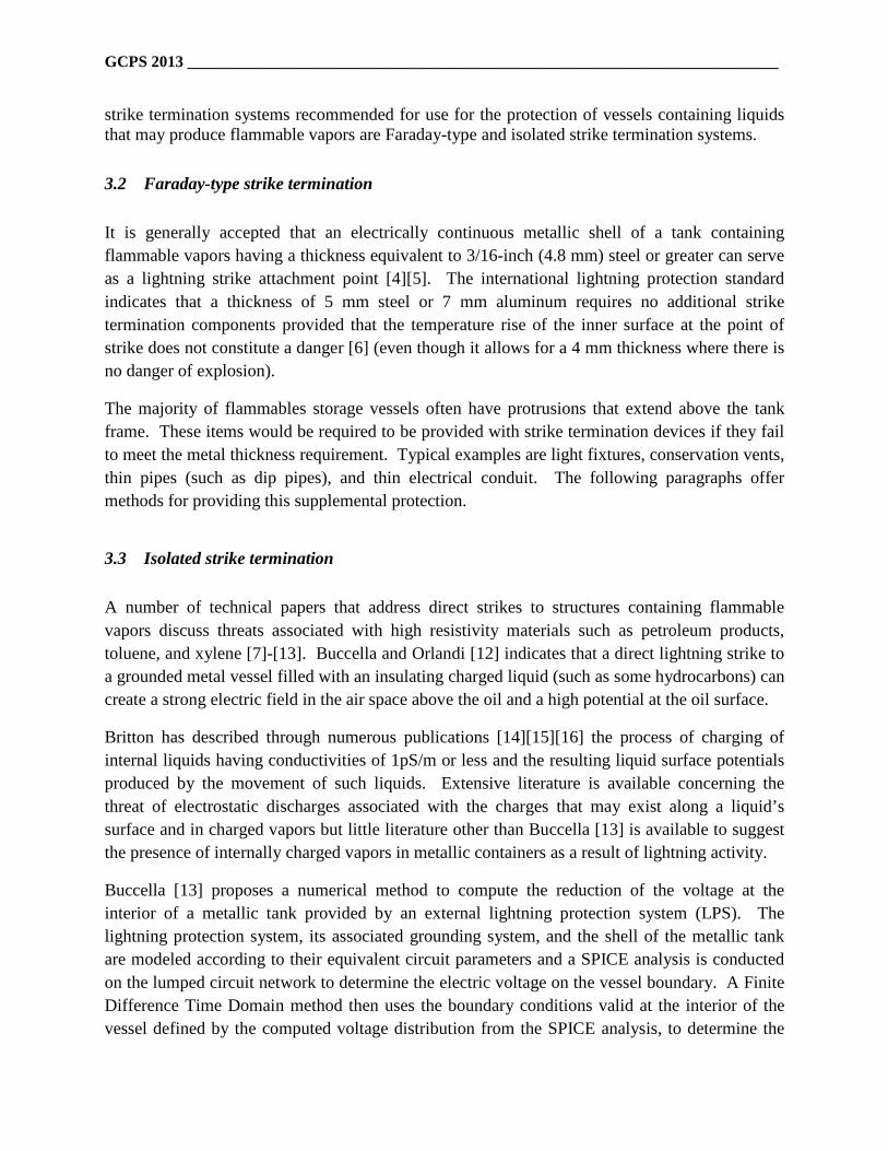
GCPS 2013 __________________________________________________________________________
strike termination systems recommended for use for the protection of vessels containing liquids that may produce flammable vapors are Faraday-type and isolated strike termination systems.
3.2 Faraday-type strike termination It is generally accepted that an electrically continuous metallic shell of a tank containing flammable vapors having a thickness equivalent to 3/16-inch (4.8 mm) steel or greater can serve as a lightning strike attachment point [4][5]. The international lightning protection standard indicates that a thickness of 5 mm steel or 7 mm aluminum requires no additional strike termination components provided that the temperature rise of the inner surface at the point of strike does not constitute a danger [6] (even though it allows for a 4 mm thickness where there is no danger of explosion).
The majority of flammables storage vessels often have protrusions that extend above the tank frame. These items would be required to be provided with strike termination devices if they fail to meet the metal thickness requirement. Typical examples are light fixtures, conservation vents, thin pipes (such as dip pipes), and thin electrical conduit. The following paragraphs offer methods for providing this supplemental protection.
3.3 Isolated strike termination A number of technical papers that address direct strikes to structures containing flammable vapors discuss threats associated with high resistivity materials such as petroleum products, toluene, and xylene [7]-[13]. Buccella and Orlandi [12] indicates that a direct lightning strike to a grounded metal vessel filled with an insulating charged liquid (such as some hydrocarbons) can create a strong electric field in the air space above the oil and a high potential at the oil surface.
Britton has described through numerous publications [14][15][16] the process of charging of internal liquids having conductivities of 1pS/m or less and the resulting liquid surface potentials produced by the movement of such liquids. Extensive literature is available concerning the threat of electrostatic discharges associated with the charges that may exist along a liquid’s surface and in charged vapors but little literature other than Buccella [13] is available to suggest the presence of internally charged vapors in metallic containers as a result of lightning activity.
Buccella [13] proposes a numerical method to compute the reduction of the voltage at the interior of a metallic tank provided by an external lightning protection system (LPS). The lightning protection system, its associated grounding system, and the shell of the metallic tank are modeled according to their equivalent circuit parameters and a SPICE analysis is conducted on the lumped circuit network to determine the electric voltage on the vessel boundary. A Finite Difference Time Domain method then uses the boundary conditions valid at the interior of the vessel defined by the computed voltage distribution from the SPICE analysis, to determine the
GCPS 2013 __________________________________________________________________________
probability of an internal voltage sufficient to initiate an internal spark of sufficient energy to ignite charged vapors that may appear in the vessel.
Buccella uses this method to provide an example of the magnitude by which the isolation of the lightning current from a tank can decrease the voltage on the internal shell of a metal tank. A 5 millimeter thick, 10 meters tall, 6.4 meter diameter steel tank filled to a height of 5 meters with a petroleum product having a conductivity of 1pS/m is considered with a 100 kA lightning impulse current having a rise time of 0.8 microseconds and time to half value of 80 microseconds (similar to those values given in IEC 62305-1 [17] as characteristic of a subsequent stroke). It is shown that a reduction of potential at the inner boundary of the container of about 90% is achieved by a LPS with 5 interconnecting conductive elements isolated from the container as little as 20 centimeters. It was also shown that increasing the spacing to 40 centimeters and/or increasing the number of parallel conductors to 10 provided little additional reduction of voltage potential on the interior of a tank.
Isolated lightning protection systems allowed by NFPA 780 [4] for the protection of structures containing flammable vapors utilize masts and/or overhead (or catenary) wires. IEC 62305-3 [6] requires that all parts of the strike termination devices and down conductors for structures containing hazardous areas shall be located a minimum of 1 m from a hazardous area, where possible.
3.4 Non-isolated or hybrid strike termination Neither United States standards nor the international lightning protection standard specifically allow a lightning protection system with air terminals and down conductors installed directly on a structure containing flammable vapors. However, it is identified in 3.2 above that the metallic shell of a tank could serve as both the strike termination device and down conductor. Buccella [12][13] explains the significant benefit from even a minor isolation of the lightning current from the shell of a tank containing a flammable atmosphere. While the authors concur with Buccella’s assessment that there is benefit to the isolation of lightning current from the shell of a flammables storage vessel that may contain charged liquids or vapors, it is unclear why a Faraday-type strike termination system is allowed and yet it may not be allowed to add an air terminal integral to the structure (properly bonded to the metal shell) to protect protrusions from the metal shell that may not meet the thickness requirements (such as lights, conservation vents, etc.). The limited use of air terminals as a supplement to a Faraday-type system to provide protection for such protrusions could be considered in future revisions of standards.
GCPS 2013 __________________________________________________________________________
4. Grounding The international lightning protection standard for structures with risk of explosion [6] requires that all tanks used for the storage of liquids that can produce flammable vapors or used to store flammable gases shall be grounded at a minimum of one point. It is recommended that this grounding component be a ground ring electrode external to the structure or a foundation earth electrode but allows that a steel tank bottom serve as the ring electrode as long as it maintains contact with the earth. For tanks in tank farms, the tanks shall be interconnected. This interconnection may be provided by electrically continuous piping. Isolated tanks (which are not interconnected with other tanks) require an additional grounding connection only when the diameter or maximum dimension exceeds 20 meters.
NFPA 780 [4] identifies that any of the following methods can provide a minimum acceptable grounding method for aboveground tanks:
(1) a grounded metallic piping system without insulated joints, (2) vertical cylindrical metallic tank of at least 6 meters (20 feet) in diameter resting on earth
or concrete, or at least 15 meters (50 feet) in diameter if resting on bituminous pavement, (3) a minimum of two grounding electrodes at maximum 30 meter (100 feet) intervals along
the perimeter of the tank. For tanks installed where an insulating membrane isolates the tank from remote earth, NFPA 780 requires grounding using method (3) above. Numerous other standards and recommended practices, including API 2003 [5] and API 545 [18], accept the minimum grounding methods identified above although neither API recommended practice identifies a minimum contact dimension (diameter or contact surface area) as in NFPA 780. Unlike NFPA 780 and API 2003, API 545 does not suggest that supplemental grounding be required when there is an elastomeric liner in or under the tank bottom; even though it would be expected to have the effect of reducing the conductivity between the tank floor and the ground. The logic is that additional paths to earth will be provided by piping and cables attached to the tank.
API recommended practices suggest that tank grounding is not an important contributing factor in the prevention of arcing, rim-seal fires, or ignition of the contents in tanks. It is agreed that the grounding method used for storage tanks has little influence on the prevention of rim-seal fires or ignition of vapors in the vicinity of a direct strike but a low impedance grounding system could have a beneficial influence on the maximum level of ground potential rise and the peak voltage that will appear on the shell of the tank. Lowering the peak voltage on the shell of a tank will reduce the probability of arcing to ungrounded or remotely grounded objects as well as between the interior of the tank shell and any charged vapor-air mixtures or liquid surface potential that may exist in the interior of the storage vessel.
It is a common assumption that the low frequency value of grounding system resistance measurements is sufficient to characterize the response of the grounding system from a direct

GCPS 2013 __________________________________________________________________________
lightning strike threat. However, Figure 1 forwards a plot of resistance and impedance versus frequency derived from measurements made on a 6 meter diameter tank sitting on a concrete base which is immersed in a mixture of sand and water [19]. The blue curve represents the overall impedance of the grounding system, the green curve represents the resistive component and the dotted red line represents the negative of the reactive component of the impedance (-X is used for clarity because it mirrors the impedance trace). The grounding system frequency response of this metal tank is similar in characteristics to the limited number of measurements of petroleum or chemical tanks made at locations worldwide (although the specific values change from site to site). As can be observed from the data provided in the figure, a very good grounding system value of approximately 1 ohm begins to increase in impedance at frequencies above 20 kHz due to inductive reactance and exceeds 40 ohms at the highest frequency of 1 MHz. The actual value of voltage that would appear during the onset of a lightning current pulse would be significantly greater than one would assume based on a calculation using only the low frequency value of grounding system resistance.
Figure 1. Impedance versus Frequency for 6 meter diameter metal tank
Grounding system impedance analysis has been reported for several applications [20][21]. However, there is not enough grounding impedance data on metallic tanks sitting on concrete pads to draw clear conclusions as to efficacy of this grounding technique. The data available

GCPS 2013 __________________________________________________________________________
does not appear to suggest that the capacitive effect noted from the impedance measurements reflects that which would be expected from analytical calculations. Additional study is recommended to determine whether this discrepancy is due to the limited amount of data currently analyzed or whether there are other factors such as interconnection of reinforcing steel in the pad, age of the concrete pad, moisture in the concrete, location of insulating membranes, or depth of concrete between the metal tank bottom and reinforcing steel in the concrete pad.
Much literature is available discussing the reduction of the overall resistance of a grounding system due to the ionization of the local earth in the proximity of grounding electrodes conducting significant impulse currents into the earth. The absolute value of the effect of such ionization varies so much by the specifics of each installation that the authors suggest the phenomena be acknowledged but not considered in the design or analysis of the response of the lightning protection grounding system.
5. Potential Equalization 5.1 General It is generally agreed that the most common cause of ignition of flammable atmospheres in and around structures housing materials that may produce flammable vapors is electrical arcing due to voltage differences between conductive objects. The primary method to reduce such electrical arcing is to equalize the potential between the grounding system for such structures and any ungrounded or independently (remotely) grounded metal objects that may be installed in or on the structure.
5.2 General bonding The general bonding requirements for lightning protection systems are applicable as the minimum acceptable potential equalization requirements for structures housing materials which may produce flammable vapors. The installation of a ground loop conductor is recommended for these applications as the primary method for interconnection of incoming conductors. In the case of metallic storage vessels, national and international standards allow metallic shell to serve as the ground loop conductor.
All incoming conductors, including piping and electrical conduit, must be interconnected with this common ground bus regardless of whether it enters the structure above or below earth. Electrically-continuous structural components such as structural steel or significant metallic ladders may be used as bonding points to transition to the equipotential ground bus where allowed by code. Permanent internal metallic components should be welded to the metal frame
GCPS 2013 __________________________________________________________________________
of a steel storage vessel where applicable to decrease the probability of insulation due to contamination from by-products such as wax or corrosive material.
Finally, attention should be paid to the length of conductor used to provide potential equalization. The inductive reactance associated with the length and routing of a conductor could result in a potential difference sufficient to cause arcing at the time of maximum current rate of rise even though it provides an effective bond at lower frequencies associated with significant current flow.
5.3 Floating roof tanks Floating roof tanks provide significant potential equalization challenges. The construction techniques required to create open top floating roof tanks present potential ignition hazards due to arcing across the non-continuous metallic surfaces. In the case of floating-roof tanks, the floating-roof must be effectively bonded to the main tank shell. This bonding is provided through the installation of shunts bonding the floating roof to the tank shell or through a metallic ladder bonded to the shell.
The design of seals and shunts and their relative locations needs to be carefully considered but is outside the scope of this paper. Additional information on the design and testing of shunts for floating roof petroleum applications can be found in API/EI Research Report 545-A [22].
Culham Laboratory conducted lightning current testing on shunt/shell interfaces and identified that flexible bonding conductors of 35 mm width and minimum thickness of 3 mm should be applied between the tank shell and the floating roof at about 1.5 m intervals around the roof periphery [22]. The bonding conductors must be arranged so that they cannot form a re-entrant loop. They also found that some sparking at the shunts cannot be avoided. Culham results indicated that even clean steel shunt/shell interfaces sparked. When these sparks occur in the vicinity of damaged or leaky seals, ignition of flammable vapors will likely occur. For such installations, maintenance of the seals is critical to reducing the susceptibility to direct and nearby lightning strikes. Immersion of the shunts in the liquid is also an option. The immersion will reduce the oxygen to levels below that which would support ignition. However, Culham reported their testing revealed that currents in immersed shunts tended to cause an eruption of fluid, due to the arc pressure. It is unclear as to whether this eruption of fluid would provide sufficient oxygen to support ignition.

GCPS 2013 __________________________________________________________________________
6. Lightning Protection Plan 6.1 General It is recommended that a lightning protection plan be developed for structures containing flammable vapors to identify the need for lightning protection, identify maintenance and inspection procedures, and establish procedures for termination of any necessary operations at the approach of a thunderstorm. Lightning risk assessments are available in both the IEC and NFPA lightning protection standards to support in determining the need for protection of structures by specific application and can also be used to determine any requirements for the termination of operations. Maintenance and Inspection recommendations are discussed below.
6.2 Maintenance and inspection IEC 62305-3 requires that lightning protection and grounding systems installed to protect structures with the risk of explosion (including flammables storage tanks) be inspected at regular periodic intervals. This inspection shall include electrical testing every 12 to 14 months as determined by the authority having jurisdiction. NFPA 780 also provides recommendations for the maintenance and inspection of lightning protection systems but is not specific to flammables applications.
Maintenance and inspection plans for flammables storage areas should be tailored to the specific application and physical limitations of the site. For example, in older plants there may not be available real estate to perform earth resistance testing of grounding systems; even when individual electrodes can be isolated. In those cases, it may be more effective to conduct point-to-point bonding testing. The use of visual inspections to verify the efficacy of bonding connections and critical installations can be very effective in many applications.
Periodic inspections for flammables storage areas should also address the inspection and maintenance of seals for floating roof tanks to minimize the probability of a flammable vapor in the vicinity where sparking may appear between the tank shell and floating roof. This is also critical for all tanks in those locations where direct attachment is most probable.
6.3 Termination of operations
There are some operations that may be susceptible to lightning activity or that may result in the generation of charged vapors. The termination of such operations may be beneficial in reducing the risk of ignition of a flammable atmosphere. For example, the loading operations of materials with conductivities of 1 pS/m or less could create an internal charge cloud that be susceptible to

GCPS 2013 __________________________________________________________________________
internal arcing. A direct or nearby lightning strike could create a collapsing electric field that could lead to an internal arc between the charged vapor and the internal wall of the metal tank, causing ignition of the contents. The use of lightning warning systems in the lightning protection plan can provide advance warning to allow the termination of any necessary operations.
7 Conclusion Some incident investigations citing lightning as a cause of ignition of flammable vapors are unable to identify the specific ignition mechanism because of the damage to the storage vessel. Some, such as Oland [10], cite the possibility that a flanged connection for a level alarm, manway, or PV valve which provided enough of a gap to produce a spark. It is critical in the analysis to not only consider the possibility of the creation of an arc but also consider whether the energy in the arc is sufficient to ignite the atmosphere.
Others cite the possibility of arcing between the tank shell and “bound space charge” inside the tank even though there is no identified charging mechanism to create such a “bound charge.” While the generation of charged liquid surfaces and vapor clouds is acknowledged, the application will produce a relaxation time for such charges. For materials with conductivities of 50 pS/m or more, the relaxation time is less than one second.
In is acknowledged that there are applications where a “minimum acceptable” lightning protection system for a structure containing flammable vapors could consist of nothing more than a 5 mm or more thick steel continuous metallic container sitting on earth, with or without a release prevention barrier membrane. The 5 mm thick shell should be sufficient to prevent burn through and a tank diameter of 6 m or more should provide enough surface area contact with earth to dissipate currents into the earth regardless of whether surface arcing is produced. The majority of these vessels will also contain numerous connections to piping and grounded electrical conduit that will provide additional paths to earth that will act as supplemental grounding electrode. However, it must also be noted that additional considerations may be required depending upon the conductivity and ignition sensitivity of the contents.
The most common failure modes resulting in ignition of flammable atmospheres is generally agreed to be arcing in the vicinity of a flammable vapor. This is most often caused by a difference in potential between ungrounded or independently grounded conductors located close enough that the potential difference exceeds the breakdown voltage of the atmosphere. This can be resolved by either increased bonding or separation of the independently grounded conductors. For floating roof tanks, the design and location of the bonds are critical.
An additional threat that must also be assessed is the thermal threat that can result from a direct strike. The thermal effect of lightning current flow is not thought to be an issue but the actual lightning attachment point may be. If the material thickness is not sufficient, burn through can occur or a hot spot sufficient to ignite the contained vapors can appear on the inner surface of the

GCPS 2013 __________________________________________________________________________
metal. This is best addressed by sufficient thickness of the shell of a tank if a Faraday-type protection system is used or to provide strike termination devices that would terminate the strike prior to attachment to the structure.
It can be shown that isolation of lightning currents from the shell of a metallic tank can reduce the voltage that can appear on the inner shell of a metallic tank. The use of isolated lightning protection systems such as masts or groups of masts interconnected by overhead wires can be particularly useful when the acceptable risk of an event is very low and the contents of the structure contains a liquid of conductivity of 1 pS/m or less. The limited use of air terminals as a supplement to a Faraday-type system to provide protection for such protrusions could be considered in future revisions of standards.
Finally, future study is suggested to determine the efficacy of the grounding electrode represented by a metallic tank sitting on a concrete pad. It is also suggested that standards committees consider the possibility of the use of a hybrid lightning protection system to allow air terminals to be installed on metal tanks to protect protrusions that may not meet the thickness requirements of a Faraday-type system.
8 References [1] “NFPA 780 Report on Comments,” National Fire Protection Association,
www.nfpa.org/Assets/files/AboutTheCodes/780/780_A2013 Report on Comments_(ROC).pdf , 1 February 2013.
[2] Kern, Alexander, “Simulation and measurement of melting effects on metal sheets caused by direct lightning strikes,” Proceedings of International Aerospace and Ground Conference on Lightning and Static Electricity, Cocoa Beach, FL, 16-19 April 1991.
[3] CUL/LT-0234, “Review of Lightning Phenomena and the Interaction with Above Ground Storage Tanks,” API/EI Research Report 545-A, “Verification of lightning protection requirements for above ground hydrocarbon storage tanks,” First Edition, American Petroleum Institute and Energy Institute London, ISBN 978 0 85293 3763, Colchester, UK, October 2009.
[4] NFPA 780, “Standard for the Installation of Lightning Protection Systems,” 2011 Edition, National Fire Protection Association, Quincy, MA, 21 June 2010.
[5] API 2003, “Protections Against Ignitions Arising Out of Static, Lightning, and Stray Currents,” API Recommended Practice, 7th Edition, American Petroleum Institute, Washington, DC, January 2008.
[6] IEC 62305-3, “Protection against lightning; Part 3: Physical damage to structures and life hazard, Annex D: Additional information for LPS in the case of structures with a risk of

GCPS 2013 __________________________________________________________________________
explosion,” Edition 2, International Electrotechnical Commission, Geneva, pp. 52-58, December 2010.
[7] H. Kramer, H. and K. Asano, “lncendivity of sparks from surface of electrostatically charged liquids”, Journal of Electrostatics, Volume 6, pp. 361-371, 1974.
[8] Asano, K. “Relaxation time of space charge in partly filled tank,” IEE Proceedings on Physical Science, Measurement and Instrumentation, Volume 137, Issue 2, pp. 111-l16, March 1990.
[9] Matsubata, Y. and T. B. Jones, “Numerical modeling for potential relaxation of charged oil containers” IEEE Transactions on Industrial Applications, Vol. 29, No. 2, pp. 295-299,1993.
[10] Oland, Jeffrey, “Tank 15 – A Perfect Storm,” 43rd Annual Loss Prevention Symposium, Paper 6F, American Institute of Chemical Engineers, Tampa, FL, April 2009.
[11] HU Hai-yan and LIU Quan-zhen, “Research on Lightning Sparks Discharge and Protection Measures of Large Floating Roof Tank”, International Conference on Lightning Protection, Paper No. 61, Vienna, Austria, 2012.
[12] Buccella, C and A. Orlandi, “An Efficient Technique for the Evaluation of Lightning-Induced Voltage in a Cylindrical Vessel Containing Charged Oil,” IEEE Transactions on Industry Applications, Volume 39, No. 2, pp.368 –373, Mar/Apr 2003.
[13] Buccella, Concettina, “An Accurate Numerical Method to Compute the Effects of the Protections Against Direct Lightning on Charged Liquid Tanks,” IEEE Industry Applications Conference 2002, Conference Record of the 37th IAS Annual Meeting, Volume 2, pp. 1006 – 1011, 13 – 18 October 2002.
[14] Britton, Laurence G. and Jack A. Smith, “Static Hazards of the VAST,” Journal of Loss Prevention in the Process Industries, Volume 25, pp. 309-328, 2012.
[15] Britton, Laurence G., Avoiding static ignition hazards in chemical operations, AIChE-CCPS Concept Book, Center for Chemical Process Safety, New York, 1999.
[16] Britton, L. G., & T.J. Williams, “Some characteristics of liquid-to-metal discharges involving a charged “low risk” oil,” Journal of Electrostatics, Volume 13, pp. 185-207, 1982.
[17] IEC 62305-1, ““Protection against lightning – Part 1: General principles,” 2nd Edition, International Electrotechnical Commission, Geneva, December 2010.

GCPS 2013 __________________________________________________________________________
[18] API 545, “Recommended Practice for Lightning Protection of Aboveground Storage Tanks for Flammable or Combustible Liquids,” First Edition, American Petroleum Institute, Washington, DC, October 2009.
[19] Rousseau, Alain and Pierre Gruet, "Measurement of a lightning earthing system", SIPDA 2005.
[20] Rousseau, Alain, Mitchell Guthrie, and Vladimir Rakov, “High Frequency Earthing Impedance Measurements at Camp Blanding, Florida,” 30th International Conference on Lightning Protection, Cagliari, Italy, September 2010.
[21] Guthrie, Mitchell, John Tobias, and Alain Rousseau, “Grounding System Design and Measurements for Critical Installations,” presented at 33rd Department of Defense Explosives Safety Seminar, Palm Springs, CA, August 2008.
[22] API/EI Research Report 545-A, “Verification of lightning protection requirements for above ground hydrocarbon storage tanks,” First Edition, American Petroleum Institute and Energy Institute London, ISBN 978 0 85293 3763, Colchester, UK, October 2009.
Additional references not cited:
[23] Diego, Arturo Galvan, “Lightning protection of structures with risk of fire and explosion,” Lightning Protection edited by Vernon Cooray, Chapter 17, pp. 821-841.
[24] Grcev, Leonid, “High-frequency grounding,” Lightning Protection edited by Vernon Cooray, Chapter 10, pp. 503-529.
[25] Golde, R.H., Lightning Protection, Chemical Publishing Co., London, 1973.
[26] Rakov, Vladamir and Martin Uman, Lightning, Physics and Effects, Cambridge University Press, ISBN 0521 583276, Cambridge, UK, 2003.

Public Comment No. 75-NFPA 780-2015 [ New Section after A.8.7.2 ]
TITLE OF NEW CONTENT
Type your content here ...
A.8.7.2.4 The conductors between the deck-level potential equalization network and grounding electrodesshould be provided at or near the location of lightning protection masts or catenary cables where practicable.
Statement of Problem and Substantiation for Public Comment
The proposed revision is necessary to provide the recommended interconnections between the deck-level potential equalization network proposed in Public Comment 74, the associated grounding electrodes, and lightning protection systems installed on the structure.
Related Public Comments for This Document
Related Comment Relationship
Public Comment No. 74-NFPA 780-2015 [Sections 8.7.2, 8.7.3] Supporting explanatory material
Related Item
Public Input No. 258-NFPA 780-2014 [Section No. 8.7.2]
First Revision No. 37-NFPA 780-2014 [Section No. 8.7.2]
Submitter Information Verification
Submitter FullName:
MITCHELL GUTHRIE
Organization: ENGINEERING CONSULTANT
Affilliation:Submitted on behalf of the Piers and Wharves Task Force of theExplosives Task Group
Street Address:
City:
State:
Zip:
Submittal Date: Wed May 13 17:10:20 EDT 2015
National Fire Protection Association Report http://submittals.nfpa.org/TerraViewWeb/ContentFetcher?commentPara...
79 of 100 5/18/2015 3:44 PM

Public Comment No. 76-NFPA 780-2015 [ Section No. A.8.7.2 ]
A.8.7.2
The purpose of the lightning protection system on the piers or wharves is requirements expressed in thisparagraph is to protect the explosives positioned on these structures from being ignited by direct lightningstrikes. A ship alongside a pier or wharf Open air explosives staging areas on a wharf will generallyrequire lightning protection from a mast or catenary system. A ship alongside an explosives handling wharfis capable of providing a zone of protection for a section of the pier or wharf. The portion of the pier orwharf used for explosives staging will require lightning protection from a mast or catenarysystem explosives handling wharf and may be considered for providing the protection for an explosives stagingarea .
Statement of Problem and Substantiation for Public Comment
The proposed revision is required to be consistent with the proposed revisions made in Public Comment 74. An additional editorial change was made to better link the purpose of the supplemented requirement and clarify that the existing last sentence is not intended to be mandatory text.
Related Public Comments for This Document
Related Comment Relationship
Public Comment No. 74-NFPA 780-2015 [Sections 8.7.2, 8.7.3] Syncronization of terminology
Related Item
Public Input No. 258-NFPA 780-2014 [Section No. 8.7.2]
First Revision No. 37-NFPA 780-2014 [Section No. 8.7.2]
Submitter Information Verification
Submitter FullName:
MITCHELL GUTHRIE
Organization: ENGINEERING CONSULTANT
Affilliation:Submitted on behalf of the Piers and Wharves Task Force of theExplosives Task Group
Street Address:
City:
State:
Zip:
Submittal Date: Wed May 13 17:32:52 EDT 2015
National Fire Protection Association Report http://submittals.nfpa.org/TerraViewWeb/ContentFetcher?commentPara...
80 of 100 5/18/2015 3:44 PM
Public Comment No. 79-NFPA 780-2015 [ Section No. A.8.10.7.7 ]
A.8.10.7.7
For methods to verify the operation of the SPD, see NFPA 70B.
Statement of Problem and Substantiation for Public Comment
PC-77 deletes 8.10.7.7 which requires removal of the supporting annex text.
Related Public Comments for This Document
Related Comment Relationship
Public Comment No. 77-NFPA 780-2015 [Section No. 8.10.7.7] Deletes 8.10.7.7
Related Item
Public Input No. 201-NFPA 780-2014 [Section No. 8.10.7.7]
First Revision No. 43-NFPA 780-2014 [Section No. 8.10.7.7]
Submitter Information Verification
Submitter Full Name: MITCHELL GUTHRIE
Organization: ENGINEERING CONSULTANT
Street Address:
City:
State:
Zip:
Submittal Date: Thu May 14 00:38:41 EDT 2015
National Fire Protection Association Report http://submittals.nfpa.org/TerraViewWeb/ContentFetcher?commentPara...
81 of 100 5/18/2015 3:44 PM

Public Comment No. 20-NFPA 780-2015 [ Section No. A.11.2.1 ]
A.11.2.1
A typical airfield lighting series (current-driven) circuit is powered by a constant current regulator (CCR) orequivalent power supply. Current is the same at all points in the series circuit. The output voltage is directlyproportional to the load and output current step. The CCR output (primary circuit) is normally ungrounded.The internal overcurrent protection of the CCR or an equivalent power supply monitors the actual outputcurrent. Series airfield lighting circuit overcurrent protection does not rely on a low impedance return path orground connection for proper operation.
The installation of an equipotential airfield lighting counterpoise system on a series circuit also providesequipotential bonding between all elements of the airfield lighting system. The airfield lighting counterpoisesystem maintains all interconnected components at earth potential and protects personnel from possiblecontact with energized metallic light bases, mounting stakes, or fixtures.
Lightning strikes often occur on the pavement, and the counterpoise conductor provides a method ofdissipating the energy as it moves from the pavement surface to the earth.
Statement of Problem and Substantiation for Public Comment
The sentence was moved from A.11.2.1 and placed at the end of A.11.4.2.6.2 during the resolution of PI No. 78 by FR-6. The text was not deleted in A.11.2.1.
Related Item
Public Input No. 78-NFPA 780-2014 [Section No. A.11.2.1]
First Revision No. 6-NFPA 780-2014 [Section No. 11.4]
Submitter Information Verification
Submitter Full Name: Carl Johnson II
Organization: AVCON, Inc.
Affilliation: none
Street Address:
City:
State:
Zip:
Submittal Date: Sat Apr 18 12:48:08 EDT 2015
National Fire Protection Association Report http://submittals.nfpa.org/TerraViewWeb/ContentFetcher?commentPara...
82 of 100 5/18/2015 3:44 PM

Public Comment No. 21-NFPA 780-2015 [ Section No. A.11.4.2.4 ]
A.11.4.2.4
A Chapter 4–compliant lightning protection system and SPDs could be installed at the airfield lighting vaultor other airfield lighting circuit power source.
The need for an airfield lighting vault building lightning protection system, SPDs, or surge arresters shouldbe determined by the Engineer of Record, based on sound engineering practices. Lightning protectionsystems, SPDs, and surge arresters are recommended for high-priority airfield lighting systems and airfieldlighting systems installed in areas with a lightning flash density greater than two flashes per squarekilometer per year.
The criteria in A.11.4.1.1 can be used to determine if the airfield lighting field circuits should be providedwith surge arresters.
A lightning risk assessment performed in accordance with Annex L can be used to determine if the airfieldlighting vault building or equivalent electrical equipment protective structure should be provided with alightning protection system and SPDs in accordance with Chapter 4.
The AHJ can determine and approve the need for the airfield lighting vault building or equivalent electricalequipment protective structure lightning protection system, SPDs, and airfield lighting circuit surgearresters.
Statement of Problem and Substantiation for Public Comment
Completes the renumbering of references necessary in support of FR-6.
Related Item
First Revision No. 6-NFPA 780-2014 [Section No. 11.4]
Submitter Information Verification
Submitter Full Name: Carl Johnson II
Organization: AVCON, Inc.
Affilliation: none
Street Address:
City:
State:
Zip:
Submittal Date: Sat Apr 18 13:12:43 EDT 2015
National Fire Protection Association Report http://submittals.nfpa.org/TerraViewWeb/ContentFetcher?commentPara...
83 of 100 5/18/2015 3:44 PM

Public Comment No. 22-NFPA 780-2015 [ Section No. A.11.4.2.6.1.2 ]
A.11.4.2.6.1.2
Airfield pavement systems design is an intricate engineering solution involving a large number of complexvariables. Operating aircraft and pavement systems interact with each other, which must be addressed bythe pavement design process. Structural designs of airfield pavement systems include determination of theoverall pavement system thickness to achieve the final design objectives. Airfield pavement systems arenormally constructed in courses or layers.
Many factors influence the pavement system layer thicknesses required to provide satisfactory pavementsystem design. Among them are the type of pavement and the load-bearing capacity of the supportingmaterials, key components that affect the structural design of the pavement system.
A typical pavement system design might consist of the following layers:
(1) Conditioned and compacted earth fill and subgrade below the pavement system (typically 100 percentcompaction required)
(2) Enhanced subbase course material, including additional layering, or enhanced existing subgrade
(3) Pavement base course (flexible or semirigid materials to support the pavement surface materials)
(4) Final pavement surface, either hot mix asphalt (HMA), a flexible pavement typically installed inmultiple layers, or Portland cement concrete (PCC), a rigid pavement typically installed in one layer
The thickness of each of the overall pavement layers is determined by the structural requirements of thepavement system based on existing conditions, aircraft sizes and weights, number of repetitions,environmental factors, and other features.
The airfield lighting system is incorporated into the airfield pavement system. The design of the depth andthe height of the various airfield lighting system components, including light bases, light base accessories,conduits, counterpoise conductors, and the like, must be adjusted to integrate the components into thevarying pavement system layer thicknesses. Although reasonable effort should be made to comply with the8 in. (200 mm) requirement contained in 11.4.2.6.1.1, it is for these reasons that the variation described in11.4.2.6.1.2 is necessary.
Statement of Problem and Substantiation for Public Comment
".........Airfield pavement systems are normally constructed in courses or layers.
Many factors influence the pavement system layer thicknesses required to provide satisfactory pavement system design......."
The hard return between the two paragraphs was omitted in the on-line version. The two paragraphs are properly shown in Fr-6
Related Item
First Revision No. 6-NFPA 780-2014 [Section No. 11.4]
Submitter Information Verification
Submitter Full Name: Carl Johnson II
Organization: AVCON, Inc.
Affilliation: none
Street Address:
City:
State:
Zip:
National Fire Protection Association Report http://submittals.nfpa.org/TerraViewWeb/ContentFetcher?commentPara...
84 of 100 5/18/2015 3:44 PM

Submittal Date: Sat Apr 18 18:06:40 EDT 2015
National Fire Protection Association Report http://submittals.nfpa.org/TerraViewWeb/ContentFetcher?commentPara...
85 of 100 5/18/2015 3:44 PM

Public Comment No. 34-NFPA 780-2015 [ Section No. K.3 ]
National Fire Protection Association Report http://submittals.nfpa.org/TerraViewWeb/ContentFetcher?commentPara...
86 of 100 5/18/2015 3:44 PM

K.3 Current Sharing Considerations.
National Fire Protection Association Report http://submittals.nfpa.org/TerraViewWeb/ContentFetcher?commentPara...
87 of 100 5/18/2015 3:44 PM

Annex G of IEC 62305-4, Protection Against Lightning — Part 4: Electrical and Electronic Systems WithinStructures, provides information concerning the current sharing that is likely between the lightningprotection conductors and the PV output circuit cabling, during a lightning event. For this analysis, itconsiders the following two cases:
(1) Where the separation distance(s) cannot be maintained between the lightning protection system andthe photovoltaic modules, and thus equipotential bonding must be applied,
(2) Where the separation distance(s) can be maintained and no bonding between the lightning protectionsystem and the photovoltaic system is required.
Depending on each case, the current sharing of the lightning current to ground is divided between thelightning protection system and the PV output circuit cabling. This in turn affects the selection (class andratings) of SPDs that will be installed on the photovoltaic system. For example, if the separation distancebetween the strike termination devices and the photovoltaic modules cannot be maintained for the specificlightning protection level (LPL) being calculated bonding distance being designed to, then the striketermination devices must be bonded to the photovoltaic module supporting rack. This then implies that thePV output circuit, will also act to carry a portion of the lightning current to ground. In its simplest form, thecurrent sharing can be considered as:
[K.3]
where:
I pk = is the peak lightning discharge current
n = is the number of parallel paths to ground
In this example where bonding is required, n is taken to be equal to the number of down conductors (1),because the PV output circuit is also considered a path to ground. This is a simplistic model but does serveto illustrate that the photovoltaic system can become involved in the conveyance of lightning current toground. This implication then also follows through to the selection of the surge protective devices (SPDs)that will be installed on the PV output circuit. In the preceding example, where the strike termination devicesare bonded to the module racks, the PV output circuit will also convey a portion of the lightning current toground.
Figure K.3 depicts a current sharing concept between the lightning protection and photovoltaic systemsand how this impacts on the various SPDs installed.
Figure K.3 Depiction of a Roof Level PV Installation Showing Typical Lightning CurrentDistribution Among Current Carrying Conductors and SPDs. (Source: modified from IEC 62305-4,Protection Against Lightning — Part 4: Electrical and Electronic Systems Within Structures,edition 3.)
National Fire Protection Association Report http://submittals.nfpa.org/TerraViewWeb/ContentFetcher?commentPara...
88 of 100 5/18/2015 3:44 PM

Statement of Problem and Substantiation for Public Comment
The phrase "calculated bonding distance" carries more meaning to the 780 user than the currently referenced "specific lightning protection level (LPL)".
Related Item
First Revision No. 121-NFPA 780-2014 [New Section after O.3]
Submitter Information Verification
Submitter Full Name: HAROLD VANSICKLE
Organization: LIGHTNING PROTECTION INSTITUTE
Street Address:
City:
State:
Zip:
Submittal Date: Thu Apr 30 14:18:39 EDT 2015
National Fire Protection Association Report http://submittals.nfpa.org/TerraViewWeb/ContentFetcher?commentPara...
89 of 100 5/18/2015 3:44 PM

Public Comment No. 72-NFPA 780-2015 [ Section No. L.2 ]
L.2 Lightning Flash Density ( N G ).
Lightning flash density, the yearly number of flashes to ground per square kilometer, can be found in FigureL.2.
Figure L.2 1997–2014 Average U.S. Lightning Flash Density Map (Flashes per Square Kilometerper Year). (Courtesy Vaisala, Inc.)
Additional Proposed Changes
File Name Description Approved
avg_fd_2005-2014_CONUS_2km_grid.png 2005-2014 Flash Density Map
Statement of Problem and Substantiation for Public Comment
The map submitted during the First Draft Proposal was not the updated map. This is corrected by replacement with the attached map.
Related Item
Public Input No. 244-NFPA 780-2014 [Section No. L.2]
Submitter Information Verification
Submitter FullName:
MITCHELL GUTHRIE
Organization: ENGINEERING CONSULTANT
Affilliation:This submission is made on behalf of the Risk Assessment TaskGroup
Street Address:
City:
State:
Zip:
Submittal Date: Wed May 13 07:47:12 EDT 2015
National Fire Protection Association Report http://submittals.nfpa.org/TerraViewWeb/ContentFetcher?commentPara...
90 of 100 5/18/2015 3:44 PM


Public Comment No. 61-NFPA 780-2015 [ Section No. L.6.6.1.2 ]
L.6.6.1.2
The annual threat of occurrence due to strikes near a structure (NM) is given by the following equation
(see Figure L.6.6.1.2):
[L.6.6.1.2]
where:
NG = lightning ground flash density in flashes/km2/year (see Section L.2)
AM = collection area of flashes near the structure (m2) (see Figure L.6.6.1.2)
AD = equivalent collection area of the structure (m2) (see Figure L.6.6.1.2)
CD = environmental coefficient (see Table L.4.2)
The collection area (AM) for flashes near the structure includes the area extending a distance of 500 m
(1640 ft) around the perimeter of the structure. For cases where NM is negative, a value of 0 is assigned to
NM.
Figure L.6.6.1.2 Collection Areas (AD, AM, AL, ADJ, AI). (Source: IEC.)
Additional Proposed Changes
File Name Description Approved
Figure_L.6.6.1.2.docx
Statement of Problem and Substantiation for Public Comment
Two typos were identified in the Figure L.6.6.1.2 from the figure from the public input. This comment corrects the typos.
Related Item
First Revision No. 137-NFPA 780-2014 [Sections L.6.6.1.2, L.6.6.1.3]
Submitter Information Verification
Submitter Full Name: DAVID MCAFEE
Organization: LIGHTNING FIRE PROTECTION CO
Street Address:
City:
National Fire Protection Association Report http://submittals.nfpa.org/TerraViewWeb/ContentFetcher?commentPara...
91 of 100 5/18/2015 3:44 PM

State:
Zip:
Submittal Date: Fri May 08 13:12:06 EDT 2015
National Fire Protection Association Report http://submittals.nfpa.org/TerraViewWeb/ContentFetcher?commentPara...
92 of 100 5/18/2015 3:44 PM

Figure L.6.6.1.2. On the Figure the Area AI is written with a typo as A1. Change it to AI. In the Notes to Figure L.6.6.1.2, The Area ADJ is written as DJ. Change it to ADJ.

Public Comment No. 67-NFPA 780-2015 [ Section No. L.6.6.1.3 ]
L.6.6.1.3
The annual threat of occurrence due to a strike to an incoming service (N L) is characterized by the
following formula:
[L.6.6.1.3]
where:
N G = lightning ground flash density in flashes/km2/year (see Section L.2)
A I L
= collection area of flashes striking the service (m2) (see Figure L.6.6.1.2)
C D = environmental coefficient of the incoming service (same as for structures per Table L.4.2 )
C T = correction factor for the presence of an HV/LV transformer located between the point of strikeand the structure
Where the value of L C L (used in the determination of A I L ) is not known, a value of 1 km is assumed
for the assessment. A default value of 500 Ωm can be used for soil resistivity (ρ) where this value cannot bedetermined.
If the installation incorporates underground cables run underneath a ground mesh, A I could be assumed to
be 0 for that cable set (N L = 0).
C T applies to line sections between the transformer and the structure. A value of 0.2 is applicable for
installations having a transformer located between the strike and the structure. Otherwise, a value of 1 isassigned to this variable.
Where
A L = 40 x L L
L L = the length of the incoming service (See Figure L.6.6.1.2)
ALSO REPLACE A I IN FORMULA L.6.6.1.3 WITH A L
Statement of Problem and Substantiation for Public Comment
The correct factor in this formula is AL not AI and needs too be replaced in all locations. The definition and formula for LL was left out in the final FIRST DRAFT and is being added.
Related Item
First Revision No. 137-NFPA 780-2014 [Sections L.6.6.1.2, L.6.6.1.3]
Submitter Information Verification
Submitter Full Name: DAVID MCAFEE
Organization: LIGHTNING FIRE PROTECTION CO
Street Address:
City:
State:
Zip:
Submittal Date: Sat May 09 12:48:33 EDT 2015
National Fire Protection Association Report http://submittals.nfpa.org/TerraViewWeb/ContentFetcher?commentPara...
93 of 100 5/18/2015 3:44 PM

Public Comment No. 68-NFPA 780-2015 [ Section No. L.6.6.3.1 ]
L.6.6.3.1 Injury to Humans.
The following equation calculates the value of injury to humans:
[L.6.6.3.1]
where:
L
A
= value for loss of human life LU
= value of loss of living injury to a Humanor living being
r T = reduction factor for type of surface soil or floor(see Table L.6.7.10)
L T = mean value of loss of life (see Table L.6.7.9)
ALSO DELETE " L A =" from formula L.6.6.3.1
Statement of Problem and Substantiation for Public Comment
The factor L SUB A is for loss of life and the factor L SUB U is for injury to living beings. These changes clarify the difference in the two factors.
Related Item
First Revision No. 140-NFPA 780-2014 [Section No. L.6.6.3]
Submitter Information Verification
Submitter Full Name: DAVID MCAFEE
Organization: LIGHTNING FIRE PROTECTION CO
Street Address:
City:
State:
Zip:
Submittal Date: Sat May 09 13:00:27 EDT 2015
National Fire Protection Association Report http://submittals.nfpa.org/TerraViewWeb/ContentFetcher?commentPara...
94 of 100 5/18/2015 3:44 PM

Public Comment No. 69-NFPA 780-2015 [ Section No. L.6.7.1 ]
L.6.7.1
Table L.6.7.1 provides values for the service environmental coefficient (C E D ).
Table L.6.7.1 Service Environmental Coefficient, C E D
Service Environment C E D
Urban with buildings exceeding 20 m high 0.01
Urban — population greater than 50,000 0.1
Suburban — residential on outskirts of cities 0.5
Rural — settled areas outside of towns and cities 1
Statement of Problem and Substantiation for Public Comment
A typo from the FR submittal changed the Environmental Coefficient to C SUB E when the correct factor should be C SUB D. This submittal makes the change back to C SUB D.
Related Item
First Revision No. 141-NFPA 780-2014 [Sections L.6.7.1, L.6.7.2, L.6.7.3]
Submitter Information Verification
Submitter Full Name: DAVID MCAFEE
Organization: LIGHTNING FIRE PROTECTION CO
Street Address:
City:
State:
Zip:
Submittal Date: Sat May 09 13:06:09 EDT 2015
National Fire Protection Association Report http://submittals.nfpa.org/TerraViewWeb/ContentFetcher?commentPara...
95 of 100 5/18/2015 3:44 PM

Public Comment No. 70-NFPA 780-2015 [ Section No. L.6.8 ]
National Fire Protection Association Report http://submittals.nfpa.org/TerraViewWeb/ContentFetcher?commentPara...
96 of 100 5/18/2015 3:44 PM

L.6.8
National Fire Protection Association Report http://submittals.nfpa.org/TerraViewWeb/ContentFetcher?commentPara...
97 of 100 5/18/2015 3:44 PM

Figure L.6.8 provides a worksheet for detailed risk assessment.
Figure L.6.8 Detailed Risk Assessment Worksheet.
National Fire Protection Association Report http://submittals.nfpa.org/TerraViewWeb/ContentFetcher?commentPara...
98 of 100 5/18/2015 3:44 PM

Additional Proposed Changes
File Name Description Approved
Changes_to_Figure_L.docx
Statement of Problem and Substantiation for Public Comment
This comment corrects a typo on page 1 of the Table.This submittal also makes changes to the Loss Factors section to clarify the difference between Loss of Life and Injury and to be consistent with the body text of the Annex is Section L.6.6.3.1
Related Item
First Revision No. 144-NFPA 780-2014 [Section No. L.6.8]
Submitter Information Verification
Submitter Full Name: DAVID MCAFEE
Organization: LIGHTNING FIRE PROTECTION CO
Street Address:
City:
State:
Zip:
Submittal Date: Sat May 09 13:09:44 EDT 2015
National Fire Protection Association Report http://submittals.nfpa.org/TerraViewWeb/ContentFetcher?commentPara...
99 of 100 5/18/2015 3:44 PM
ChangestoFigureL.6.81.OnPage1;StrikesNearanIncomingService CHANGESeeTableL.6.7.2toL.6.7.1Thiscorrectsatypo.ThesubmittalchangedthistoTablel.6.7.1.2.OnPage2;LossFactors;InjuryorLossofLife‐LA–DELETE“Injuryor”ThisclarifiesthatthefactorLAisforLOSSOFLIFE3.OnPage2,InjurytoHumans;DELETEtheFactorLAinTHREEplaces.DELETEthefactorLTandreplaceitwithLU.ThishelpstoclarifythatLUisforinjurytohumans.ThisalsocorrectsatypoasthefactorLTshouldhavebeenLU.TheseitemswerepartofFR‐144.

Public Comment No. 97-NFPA 780-2015 [ Section No. O.1.2.8 ]
O.1.2.8 Other Publications.
López, R. E., and L. R. Holle. “Lightning Casualties and Damages in the United States from 1959 to 1994,”Journal of Climate, 13 Issue 19 (October 2000): 3448–3464.
Moore, C. B., W. Rison, J. Mathis, and G. Aulich. “Lightning Rod Improvement Studies,” Journal of AppliedMeteorology, 39:593–609.
Guthrie, Mitchell and Alain Rousseau, “Lightning Related Ignition Mechanism an Associated Protection
Techniques for Storage Applications,” Proceedings of 9 th Global Conference on Process Safety , May2013.
Statement of Problem and Substantiation for Public Comment
The addition of the citation provides access information for the paper discussed in annex material proposed in PC-95.
Related Public Comments for This Document
Related Comment Relationship
Public Comment No. 53-NFPA 780-2015 [New Section after 7.4.2.2] original text
Public Comment No. 95-NFPA 780-2015 [New Section afterA.7.4.1.2]
annex material containingreference
Related Item
First Revision No. 146-NFPA 780-2014 [Chapter 7]
Submitter Information Verification
Submitter Full Name: MITCHELL GUTHRIE
Organization: ENGINEERING CONSULTANT
Street Address:
City:
State:
Zip:
Submittal Date: Fri May 15 14:46:44 EDT 2015
National Fire Protection Association Report http://submittals.nfpa.org/TerraViewWeb/ContentFetcher?commentPara...
100 of 100 5/18/2015 3:44 PM


![Untitled-3 [] using.pdf · Grounding Conductor Protective Conductor 6. (Ground Rod Grounding Electrode Earth Electrode) 16 (5/8 2.40 7. a18Gi0hñõu (Grounding Electrode](https://img.dokumen.tips/doc/110x75/5f88252e30e96c229e75bb1a/untitled-3-usingpdf-grounding-conductor-protective-conductor-6-ground-rod.jpg)