Embed Size (px)
Citation preview

Dave Collett April 26, 2010 www.convectivedigital.com/guide
For Training Purposes Only
1
Boeing 757-767 Study Guide
Memory Items
Aborted Engine Start
Fuel Control switch (affected side) – CUTOFF
Airspeed Unreliable
Check the pitch attitude and thrust. If pitch attitude or thrust is not normal for phase of flight: Autopilot disengage switch – Push Autothrottle disconnect switch – Push F/D switches (both) – OFF Establish normal pitch attitude and thrust setting for phase of
flight
Cabin Altitude or Rapid
Depressurization
Don the oxygen masks. Establish crew communications.
Dual Engine Failure
Engine Start selectors (both) – FLT Thrust Levers (both) – Idle Fuel Control switches (both) – CUTOFF, then RUN
Engine Fire or Engine Severe
Damage or Separation
Autothrottle Arm switch – OFF Thrust Lever (affected side) – Confirm – Idle
Engine Limit or Surge or Stall
Autothrottle Arm switch – OFF Thrust Lever (affected side) – Confirm – Retard until
indications remain within normal limits or the thrust lever is at Idle
Dave Collett April 26, 2010 www.convectivedigital.com/guide
For Training Purposes Only
2
Recall Limitations
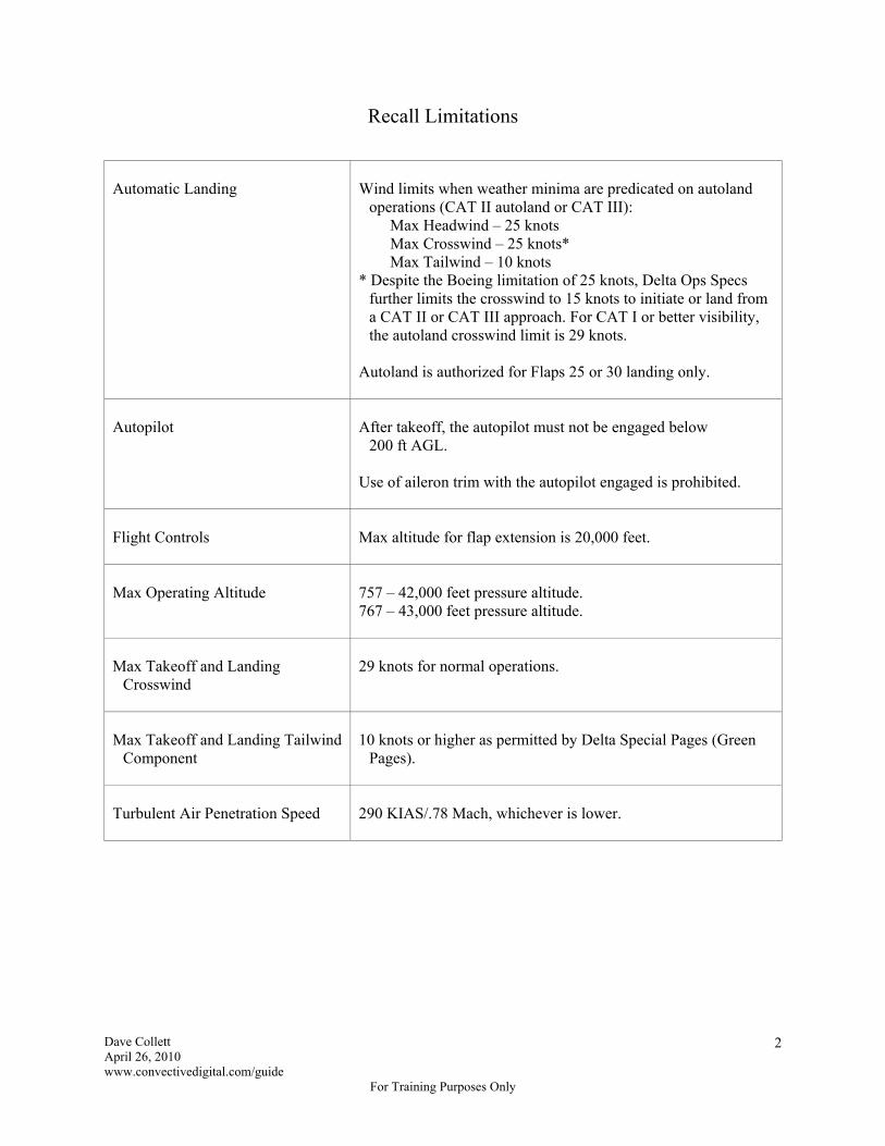
Automatic Landing
Wind limits when weather minima are predicated on autoland
operations (CAT II autoland or CAT III): Max Headwind – 25 knots Max Crosswind – 25 knots* Max Tailwind – 10 knots
* Despite the Boeing limitation of 25 knots, Delta Ops Specs further limits the crosswind to 15 knots to initiate or land from a CAT II or CAT III approach. For CAT I or better visibility, the autoland crosswind limit is 29 knots.
Autoland is authorized for Flaps 25 or 30 landing only.
Autopilot
After takeoff, the autopilot must not be engaged below
200 ft AGL. Use of aileron trim with the autopilot engaged is prohibited.
Flight Controls
Max altitude for flap extension is 20,000 feet.
Max Operating Altitude
757 – 42,000 feet pressure altitude. 767 – 43,000 feet pressure altitude.
Max Takeoff and Landing
Crosswind
29 knots for normal operations.
Max Takeoff and Landing Tailwind
Component
10 knots or higher as permitted by Delta Special Pages (Green
Pages).
Turbulent Air Penetration Speed
290 KIAS/.78 Mach, whichever is lower.

Dave Collett April 26, 2010 www.convectivedigital.com/guide
For Training Purposes Only
3
Non-Recall Limitations
ACARS
ACARS is limited to the transmission and receipt of messages which
will not create an unsafe condition if the message is improperly received, however Pre-Departure, Digital ATIS, Oceanic Clearances, Weight and Balance, and Takeoff Data messages can be transmitted and received over ACARS if they are verified per approved operational procedures.
Aircraft Cooling
When the airplane is electrically powered for more than 20 minutes
on the ground and the outside air temperature is 34ºC (94ºF) or greater, equipment cooling must be provided in accordance with the table in the Limitations section.
Automatic Landing
Do not use the autopilot below 100 feet Radio Altitude at airport
pressure altitudes above 8,400 feet. Do not autoland the aircraft when ground speed exceeds 165 knots.
Door Mounted Escape Slides
Entry door evacuation slide systems must be armed and engagement
of the girt bar with the door sill verified prior to taxi, takeoff or landing whenever passengers are carried.
EGPWS
Do not use the terrain display for navigation. Terrain awareness alerting and terrain display functions are
prohibited within 15 nm of takeoff, approach or landing on a runway or airport not contained in the EGPWS airport database. Crews will be notified of those runways/airports via EFCB or flight plan remarks.
Look-ahead and Terrain alerting and display functions must be inhibited by selecting the Ground Proximity Terrain Override switch to OVRD if: the FMS is operating in IRS NAV only prior to takeoff, FMS position updating is not accomplished or
actual runway position is not verified by ensuring, with the 5 or 10 nm range selected on the EFIS control panel, the airplane is displayed at the appropriate point on the runway symbol
EGT Limitations
EGT limitations vary by airplane and engine. Refer to the
Limitations section. 757 – If start EGT surpasses 485ºC (red radial) but does not exceed
545ºC, engine shut down is not required. Make a logbook entry and contact MCC prior to dispatch for further guidance.
767 – If maximum engine start limits are exceeded, shut down the engine. Maintenance action is required prior to further operation.

Dave Collett April 26, 2010 www.convectivedigital.com/guide
For Training Purposes Only
4
Engine Emergency Conditions
The published operating limits for engines relate to predefined
normal and abnormal operations. If, however, any crew finds itself in a life-threatening situation which requires an application of thrust beyond the certified takeoff limits, they can feel confident that the engine(s) will operate satisfactorily for whatever reasonable time is required to maintain safe control of the aircraft.
Engine Ignition
Continuous ignition must be on (Engine Start Selector in the CONT
position) while operating in severe turbulence. Continuous ignition is automatically provided with the flap lever out
of the UP position or in icing conditions when engine anti-ice is on.
Engine Indicating
The flight crew shall not blank engine vibration display during
takeoff.
Engine Limit Display Markings
Minimum and maximum limits are red. Caution limits are amber.
Flight Controls
Avoid rapid and large alternating control inputs, especially in
combination with large changes in pitch, roll or yaw (e.g. large side slip angles) as they may result in structural failure at any speed, including below VA (maneuvering speed).
Flight Deck Access System
Verify that an operational check of the Flight Deck Access System
has been accomplished according to approved procedures once each flight day.
Fuel System
Use of Jet B and JP4 fuel is prohibited. The maximum fuel temperature is 49ºC (120ºF). The maximum fuel imbalance for dispatch is 1,500 pounds. The minimum inflight fuel tank temperature for Jet A is -37ºC. Other
fuels have lower minimum temperatures. Refer to the Limitations section
If the main tanks are not full, the zero fuel gross weight of the airplane plus the weight of center tank fuel may exceed the maximum zero fuel gross weight by up to 5,000 pounds for takeoff, climb, cruise, descent and landing, provided that the effects of balance (CG) have been considered. Reference SP 12, Center Fuel Tank Procedures.
767-300 – The center tank may contain up to 22,050 pounds of fuel with less than full main tanks provided center tank weight plus actual zero fuel weight does not exceed the maximum zero fuel weight, and center of gravity limits are observed. With the fuel jettison system installed and activated, total fuel must not be less than 10,300 pounds in the main tanks.
Dave Collett April 26, 2010 www.convectivedigital.com/guide
For Training Purposes Only
5
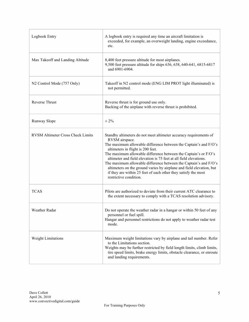
Logbook Entry
A logbook entry is required any time an aircraft limitation is
exceeded, for example, an overweight landing, engine exceedance, etc.
Max Takeoff and Landing Altitude
8,400 feet pressure altitude for most airplanes. 9,500 feet pressure altitude for ships 636, 638, 640-641, 6815-6817
and 6901-6904.
N2 Control Mode (757 Only)
Takeoff in N2 control mode (ENG LIM PROT light illuminated) is
not permitted.
Reverse Thrust
Reverse thrust is for ground use only. Backing of the airplane with reverse thrust is prohibited.
Runway Slope
± 2%
RVSM Altimeter Cross Check Limits
Standby altimeters do not meet altimeter accuracy requirements of
RVSM airspace. The maximum allowable difference between the Captain’s and F/O’s
altimeters in flight is 200 feet. The maximum allowable difference between the Captain’s or F/O’s
altimeter and field elevation is 75 feet at all field elevations. The maximum allowable difference between the Captain’s and F/O’s
altimeters on the ground varies by airplane and field elevation, but if they are within 25 feet of each other they satisfy the most restrictive condition.
TCAS
Pilots are authorized to deviate from their current ATC clearance to
the extent necessary to comply with a TCAS resolution advisory.
Weather Radar
Do not operate the weather radar in a hangar or within 50 feet of any
personnel or fuel spill. Hangar and personnel restrictions do not apply to weather radar test
mode.
Weight Limitations
Maximum weight limitations vary by airplane and tail number. Refer
to the Limitations section. Weights may be further restricted by field length limits, climb limits,
tire speed limits, brake energy limits, obstacle clearance, or enroute and landing requirements.
Dave Collett April 26, 2010 www.convectivedigital.com/guide
For Training Purposes Only
6
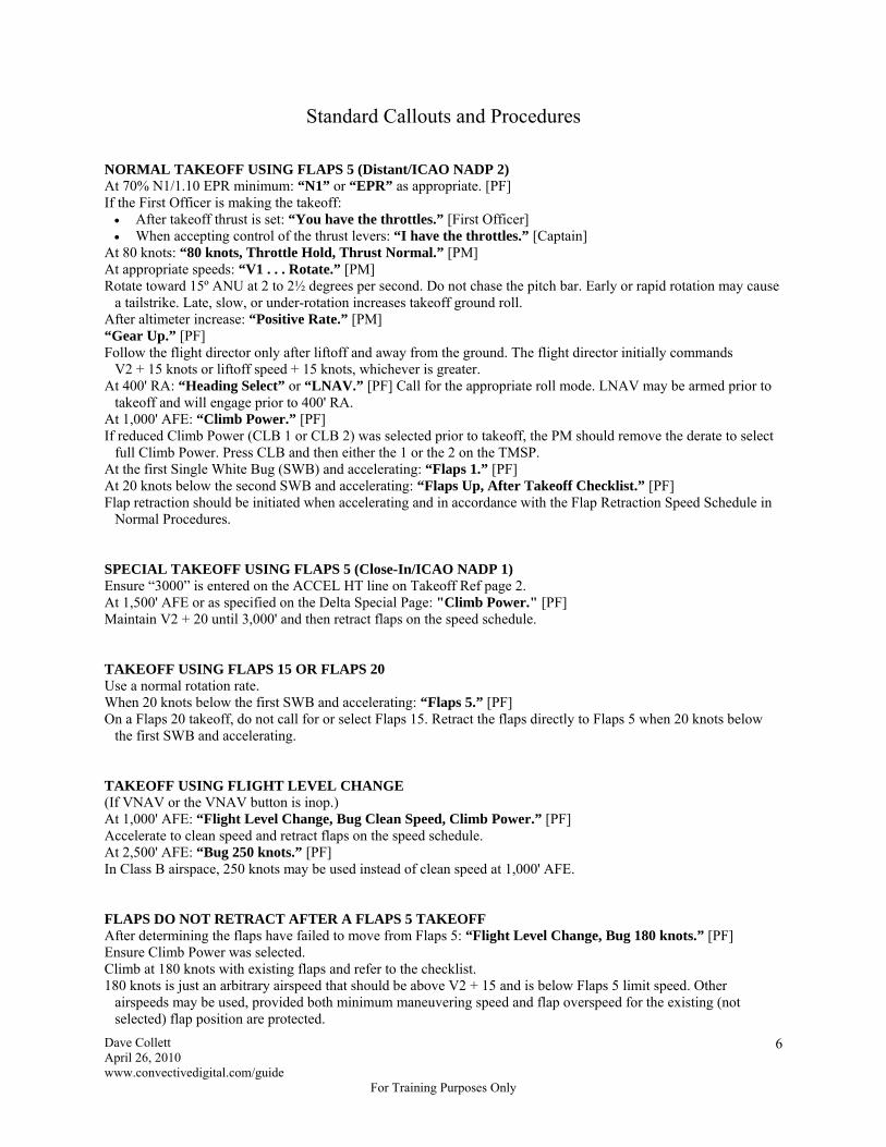
Standard Callouts and Procedures NORMAL TAKEOFF USING FLAPS 5 (Distant/ICAO NADP 2) At 70% N1/1.10 EPR minimum: “N1” or “EPR” as appropriate. [PF] If the First Officer is making the takeoff: After takeoff thrust is set: “You have the throttles.” [First Officer] When accepting control of the thrust levers: “I have the throttles.” [Captain]
At 80 knots: “80 knots, Throttle Hold, Thrust Normal.” [PM] At appropriate speeds: “V1 . . . Rotate.” [PM] Rotate toward 15º ANU at 2 to 2½ degrees per second. Do not chase the pitch bar. Early or rapid rotation may cause
a tailstrike. Late, slow, or under-rotation increases takeoff ground roll. After altimeter increase: “Positive Rate.” [PM] “Gear Up.” [PF] Follow the flight director only after liftoff and away from the ground. The flight director initially commands
V2 + 15 knots or liftoff speed + 15 knots, whichever is greater. At 400' RA: “Heading Select” or “LNAV.” [PF] Call for the appropriate roll mode. LNAV may be armed prior to
takeoff and will engage prior to 400' RA. At 1,000' AFE: “Climb Power.” [PF] If reduced Climb Power (CLB 1 or CLB 2) was selected prior to takeoff, the PM should remove the derate to select
full Climb Power. Press CLB and then either the 1 or the 2 on the TMSP. At the first Single White Bug (SWB) and accelerating: “Flaps 1.” [PF] At 20 knots below the second SWB and accelerating: “Flaps Up, After Takeoff Checklist.” [PF] Flap retraction should be initiated when accelerating and in accordance with the Flap Retraction Speed Schedule in
Normal Procedures. SPECIAL TAKEOFF USING FLAPS 5 (Close-In/ICAO NADP 1) Ensure “3000” is entered on the ACCEL HT line on Takeoff Ref page 2. At 1,500' AFE or as specified on the Delta Special Page: "Climb Power." [PF] Maintain V2 + 20 until 3,000' and then retract flaps on the speed schedule. TAKEOFF USING FLAPS 15 OR FLAPS 20 Use a normal rotation rate. When 20 knots below the first SWB and accelerating: “Flaps 5.” [PF] On a Flaps 20 takeoff, do not call for or select Flaps 15. Retract the flaps directly to Flaps 5 when 20 knots below
the first SWB and accelerating. TAKEOFF USING FLIGHT LEVEL CHANGE (If VNAV or the VNAV button is inop.) At 1,000' AFE: “Flight Level Change, Bug Clean Speed, Climb Power.” [PF] Accelerate to clean speed and retract flaps on the speed schedule. At 2,500' AFE: “Bug 250 knots.” [PF] In Class B airspace, 250 knots may be used instead of clean speed at 1,000' AFE. FLAPS DO NOT RETRACT AFTER A FLAPS 5 TAKEOFF After determining the flaps have failed to move from Flaps 5: “Flight Level Change, Bug 180 knots.” [PF] Ensure Climb Power was selected. Climb at 180 knots with existing flaps and refer to the checklist. 180 knots is just an arbitrary airspeed that should be above V2 + 15 and is below Flaps 5 limit speed. Other
airspeeds may be used, provided both minimum maneuvering speed and flap overspeed for the existing (not selected) flap position are protected.

Dave Collett April 26, 2010 www.convectivedigital.com/guide
For Training Purposes Only
7
LOW ALTITUDE HOLD DOWN (If altitude capture prevents the selection of any other pitch mode.) If ALT CAP occurs before CLB power is selected at 1,000' AFE, the TMC will remain in Takeoff, the
autothrottles will remain in Throttle Hold, and the airplane will accelerate and overspeed the flaps unless pilot action is taken. Either manually retard the throttles to prevent flap overspeed or select CLB power, bug clean speed and engage the autothrottles in SPD. The callout for the latter option is:
At 1,000' AFE: “Climb Power, Bug Clean Speed, Autothrottles – Speed.” [PF] (CBS) If ALT CAP occurs after CLB power is selected at 1,000' AFE, the autothrottles will engage in Speed mode,
the MCP speed window will open to the current airspeed, and the autothrottles will retard to maintain the current speed. In this case, simply rotate the speed bug to clean speed, ensure the autothrottles are in SPD mode and retract the flaps on schedule.
In Class B airspace, 250 knots may be used instead of clean speed at 1,000' AFE. TWO ENGINE GO-AROUND “Missed Approach” or “Go-Around.” [Captain] Press a G/A switch and advance power. The autothrottles will engage if not already engaged unless the A/T ARM
switch is off. Ensure G/A is displayed on the ADI for pitch, roll and A/T modes. Rotate toward 15º ANU and follow the flight director. “Flaps 20.” [PF] After altimeter increase: “Positive Rate.” [PM] “Gear Up.” [PF] Maintain Vref 25/30 + speed additive (orange bug speed) minimum. The pitch bar initially commands the greater of MCP airspeed or the airspeed at time of G/A engagement. The roll bar initially commands the ground track at time of G/A engagement. The autothrottles provide at least a 2,000 fpm rate of climb. If full thrust is desired, manually advance the thrust
levers to maximum go-around thrust. Report the missed approach to ATC. [PM] If conditions permit, the PM should report the missed approach and
receive a clearance before the PF calls for a roll mode so you know whether to fly the published missed approach procedure, runway heading, or some other clearance.
At 400' RA: “Heading Select" or “LNAV.” [PF] Call for the appropriate roll mode. At 1,000' AFE: “Bug Flaps 5 Speed.” [PF] Set the airspeed command bug to Flaps 5 speed (first SWB) at 1,000' AFE and follow the flight director pitch bar as
it lowers the nose to accelerate. Do not call for or select Flight Level Change; stay in G/A for pitch and power. (If you’re pushing a square button on the MCP at 1,000' AFE on a go-around, you’re doing something wrong.)
At 20 knots below the first SWB and accelerating: “Flaps 5.” [PF] Normally fly the missed approach with Flaps 5 and at Flaps 5 speed. The flaps may be retracted on the speed
schedule if desired or if diverting to an alternate airport, but Flaps 5 speed will keep the aircraft slow enough to enter holding at low altitude if necessary. Max holding speed at 6,000' MSL and below is 200 knots.
It’s easiest just to stay in G/A for pitch and power as described above until level off at the missed approach altitude, but selecting VNAV or Flight Level Change is acceptable after reaching the planned flap setting (Flaps 5 or Up) and the appropriate maneuvering speed, if desired.
The autopilot will not engage in G/A mode. If the autopilot is engaged with the Flight Director in G/A, it will engage in Vertical Speed and Heading Hold, so make the necessary changes on the MCP to fly the correct vertical and horizontal path. One method is to engage the autopilot and then reselect Go-Around and the appropriate roll mode.
“After Takeoff Checklist.” [PF]
Dave Collett April 26, 2010 www.convectivedigital.com/guide
For Training Purposes Only
8
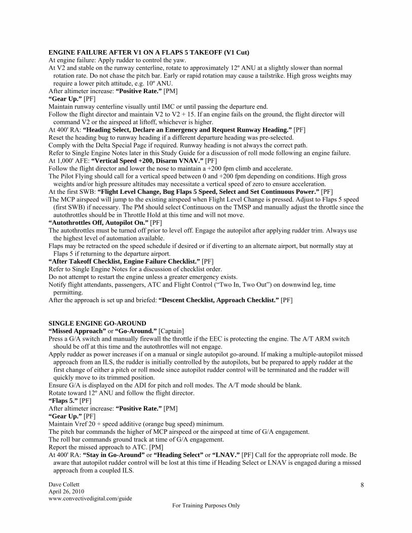
ENGINE FAILURE AFTER V1 ON A FLAPS 5 TAKEOFF (V1 Cut) At engine failure: Apply rudder to control the yaw. At V2 and stable on the runway centerline, rotate to approximately 12º ANU at a slightly slower than normal
rotation rate. Do not chase the pitch bar. Early or rapid rotation may cause a tailstrike. High gross weights may require a lower pitch attitude, e.g. 10º ANU.
After altimeter increase: “Positive Rate.” [PM] “Gear Up.” [PF] Maintain runway centerline visually until IMC or until passing the departure end. Follow the flight director and maintain V2 to V2 + 15. If an engine fails on the ground, the flight director will
command V2 or the airspeed at liftoff, whichever is higher. At 400' RA: “Heading Select, Declare an Emergency and Request Runway Heading.” [PF] Reset the heading bug to runway heading if a different departure heading was pre-selected. Comply with the Delta Special Page if required. Runway heading is not always the correct path. Refer to Single Engine Notes later in this Study Guide for a discussion of roll mode following an engine failure. At 1,000' AFE: “Vertical Speed +200, Disarm VNAV.” [PF] Follow the flight director and lower the nose to maintain a +200 fpm climb and accelerate. The Pilot Flying should call for a vertical speed between 0 and +200 fpm depending on conditions. High gross
weights and/or high pressure altitudes may necessitate a vertical speed of zero to ensure acceleration. At the first SWB: “Flight Level Change, Bug Flaps 5 Speed, Select and Set Continuous Power.” [PF] The MCP airspeed will jump to the existing airspeed when Flight Level Change is pressed. Adjust to Flaps 5 speed
(first SWB) if necessary. The PM should select Continuous on the TMSP and manually adjust the throttle since the autothrottles should be in Throttle Hold at this time and will not move.
“Autothrottles Off, Autopilot On.” [PF] The autothrottles must be turned off prior to level off. Engage the autopilot after applying rudder trim. Always use
the highest level of automation available. Flaps may be retracted on the speed schedule if desired or if diverting to an alternate airport, but normally stay at
Flaps 5 if returning to the departure airport. “After Takeoff Checklist, Engine Failure Checklist.” [PF] Refer to Single Engine Notes for a discussion of checklist order. Do not attempt to restart the engine unless a greater emergency exists. Notify flight attendants, passengers, ATC and Flight Control (“Two In, Two Out”) on downwind leg, time
permitting. After the approach is set up and briefed: “Descent Checklist, Approach Checklist.” [PF] SINGLE ENGINE GO-AROUND “Missed Approach” or “Go-Around.” [Captain] Press a G/A switch and manually firewall the throttle if the EEC is protecting the engine. The A/T ARM switch
should be off at this time and the autothrottles will not engage. Apply rudder as power increases if on a manual or single autopilot go-around. If making a multiple-autopilot missed
approach from an ILS, the rudder is initially controlled by the autopilots, but be prepared to apply rudder at the first change of either a pitch or roll mode since autopilot rudder control will be terminated and the rudder will quickly move to its trimmed position.
Ensure G/A is displayed on the ADI for pitch and roll modes. The A/T mode should be blank. Rotate toward 12º ANU and follow the flight director. “Flaps 5.” [PF] After altimeter increase: “Positive Rate.” [PM] “Gear Up.” [PF] Maintain Vref 20 + speed additive (orange bug speed) minimum. The pitch bar commands the higher of MCP airspeed or the airspeed at time of G/A engagement. The roll bar commands ground track at time of G/A engagement. Report the missed approach to ATC. [PM] At 400' RA: “Stay in Go-Around” or “Heading Select” or “LNAV.” [PF] Call for the appropriate roll mode. Be
aware that autopilot rudder control will be lost at this time if Heading Select or LNAV is engaged during a missed approach from a coupled ILS.

Dave Collett April 26, 2010 www.convectivedigital.com/guide
For Training Purposes Only
9
Comply with engine-out missed approach or engine-out rejected landing procedures on the Delta Special Page, if published. Refer to Single Engine Notes for a discussion of roll mode on a single-engine missed approach.
At 1,000' AFE: “Bug Flaps 5 Speed.” [PF] Set the airspeed command bug to Flaps 5 speed (first SWB) at 1,000' AFE and follow the flight director pitch bar as
it lowers the nose to accelerate. Do not call for or select Flight Level Change; stay in G/A for pitch. (If you’re pushing a square button on the MCP at 1,000' AFE on a go-around, you’re doing something wrong.)
Engage the autopilot after applying rudder trim if it’s not already engaged. Always use the highest level of automation available. The autopilot will not engage in G/A mode, however, and will engage in Vertical Speed and Heading Hold instead, so make the necessary changes on the MCP. One method is to engage the autopilot and then reselect Go-Around and the appropriate roll mode.
Flaps may be retracted on the speed schedule if desired or if diverting to an alternate airport. If diverting, select and set Continuous power on the operating engine for the climb to cruise altitude. Do not keep the engine firewalled.
“After Takeoff Checklist.” [PF] SINGLE ENGINE NOTES A takeoff alternate is required if the weather is below CAT I minimums. After initial rudder input is applied on takeoff, lock your heel to the floor and hold. Initially keep the rudder constant
and control ground track with ailerons after airborne. To aid in aircraft control, do not rotate until heading is stable and airspeed is equal to or greater than VR. Rotation at
V2 is recommended. Use visual references to maintain runway centerline as long as possible. During rotation the rising nose will block airflow to the tail making the rudder less effective. Be ready for an
increase in yaw during initial rotation and apply aileron (preferred) or additional rudder as necessary. Imagine a 747 waiting to cross the runway at the departure end and don’t drift into it after airborne. Maintain
runway centerline visually and “fly through the goalposts.” Departure priorities after an engine failure on takeoff:
1. Delta Special Page engine-out departure procedure 2. straight out until flaps are retracted or minimum safe maneuvering airspeed is reached
Departure priorities for an engine-out missed approach: 1. Delta Special Page engine-out departure procedure 2. published missed approach procedure if directed by the Delta Special Page engine-out departure procedure 3. as requested by ATC only if terrain clearance can be assured
Departure priorities for an engine-out rejected landing in IMC or when terrain clearance cannot be visually assured: 1. Delta Special Page engine-out rejected landing table 2. published missed approach procedure if directed by the Delta Special Page engine-out rejected landing table 3. Delta Special Page engine-out departure procedure 4. as directed by ATC
Selecting the correct roll mode at 400' RA and flying the correct path with an engine failure can be critical for obstacle clearance. Review and brief the Delta Special Pages prior to every takeoff and every approach so you know what roll mode to select and what path to fly if necessary. Do not just automatically fly straight ahead. LNAV or Heading Select and a turn may be required to comply with engine-out restrictions and avoid terrain.
If obstacle clearance is not a factor, however, you can request either runway heading or a straight-out departure. If you request runway heading you must maintain runway heading ±10º to meet Qualification Standards. If you ask for a straight-out departure you must follow the extended runway centerline on the HSI ±10º. When hand flying, requesting runway heading is easier because you can use the flight director to help maintain heading and you don’t have to compensate for wind. If you get off the heading all you need to do is correct back to it. On the other hand, if you request a straight-out departure and get off the extended runway centerline displayed on the HSI, you must correct back to the centerline and then compensate for wind to stay on it. If multiple autopilots are engaged, however, as they might be during a single-engine missed approach from an ILS, requesting a straight-out departure is easier because you can leave the autopilot in G/A and it will follow the ground track at time of engagement, which should be pretty close to the runway centerline. This avoids having to engage Heading Select at 400' RA and losing autopilot rudder control which would require rudder input to prevent the airplane from rolling. Of course, when another pitch or roll mode is selected later in the missed approach or when the autopilot transitions to Altitude Capture approaching the missed approach altitude, autopilot rudder control will be terminated and rudder input will be necessary, but that’s better than at 400' RA. As a general rule, therefore, if obstacle clearance is not a

Dave Collett April 26, 2010 www.convectivedigital.com/guide
For Training Purposes Only
10
factor, request runway heading if an engine fails on takeoff and request a straight-out departure in the event of a missed approach if you’ll be flying a single-engine ILS with the autopilot engaged, as you probably would in the real world.
Both the appropriate Non-Normal checklist and the After Takeoff checklist must be completed and the order is at the Captain’s discretion and depends on the circumstances. For a simple engine failure, completing the After Takeoff checklist first is recommended because you will catch configuration errors and it’s a more normal flow pattern. If the engine is burning or surging, however, completing the Engine Fire or Severe Damage or Separation checklist or the Engine Limit or Surge or Stall checklist first would be more appropriate.
If an engine fails on a Flaps 15 or Flaps 20 takeoff, the procedure is the same except that when 20 knots below the first SWB and accelerating at Vertical Speed +200, call for “Flaps 5.” [PF]
If an engine fails after takeoff below 1,000 feet AFE, apply rudder, lower pitch to approximately 12º ANU, maintain V2 to V2 + 15 and apply normal V1 Cut procedures at 1,000' AFE.
If an engine fails on climbout above 1,000 feet AFE, don’t do the V1 Cut procedures. Just apply rudder and lower the nose to maintain the airspeed for whatever flaps are extended.
A CAT I approach (ILS or non-precision) to a hand-flown landing is the lowest authorized approach on single engine.
Use the autopilot on approach at least until reaching visual conditions. It may be used until just prior to the flare on an ILS if desired.
Autoland is not authorized with an engine inoperative unless the engine fails below Alert Height on a CAT III. To control airspeed during level offs on a single-engine, watch the drum in the airspeed indicator and manually
adjust the thrust lever at a rate which keeps the drum from rotating. The airspeed drum provides better information than the airspeed pointer.
Keep the rudder trimmed or the autopilot will disconnect and the airplane will roll abruptly. Watch the yoke angle, which is a measure of autopilot aileron input, for indications of needed rudder trim and adjust as necessary.
The Fuel Config light will probably illuminate on downwind due to a fuel imbalance. The light must be noted and the imbalance checked, but it is not necessary to balance the fuel. The airplane will be fully controllable even with the imbalance, so leave the fuel pumps on and the fuel crossfeed valve closed. Don’t just open the crossfeed valve and leave it open (like we used to do) because it’s possible for a strong pump on the operating engine side to make the imbalance worse. If diverting to another airport, however, balancing fuel enroute would be appropriate.
On a single-engine ILS, lower the gear and select Flaps 20 at 1½ dots on the glideslope. The airplane will balloon when flaps are extended, especially when extending to Flaps 20. If hand flying, be ready to
compensate with forward yoke pressure to maintain altitude. To meet Qualification Standards, you must control the balloon and intercept the glideslope within 100 feet of your assigned glideslope intercept altitude.
If diverting and using VNAV, select and execute the ENG OUT prompt on the CLB or CRZ page. On climbout during a single-engine missed approach from a coupled ILS, the autopilot is controlling the rudder.
Rudder trim may be pre-set to 10 units so it will be approximately correct at level off when thrust is reduced and rudder control is terminated.
ACARS automatically sends a message to the Company if a fuel control switch is moved to cutoff during flight. Approximate Rudder Trim
Initial climbout – 15 units Level flight – 10 units Final approach – 5 units
Approximate Power Settings
Level flight on downwind: 83% N1 or 1.18 EPR On final approach: 73% N1 or 1.08 EPR
Qualification Standards
On initial climbout: ± 10º of heading or extended runway centerline and V2 to V2 + 15 knots On downwind: ± 10º of heading, ± 10 knots of airspeed and ± 100 feet of altitude Glideslope intercept: within 100 feet of the assigned glideslope intercept altitude (no balloon) On final approach at DH: -5 to +10 knots of airspeed, ± ½ dot on the localizer and ± 1 dot on the glideslope

Dave Collett April 26, 2010 www.convectivedigital.com/guide
For Training Purposes Only
11
Callout Summary NORMAL TAKEOFF USING FLAPS 5 At 70% N1/ 1.1 EPR minimum: “N1” or “EPR.” [PF] If the First Officer is making the takeoff: “You have the throttles.” [First Officer] “I have the throttles.” [Captain]
At 80 knots: “80 knots, Throttle Hold, Thrust Normal.” [PM] At appropriate speeds: “V1 . . . Rotate.” [PM] After altimeter increase: “Positive Rate.” [PM] “Gear Up.” [PF] At 400' RA: “Heading Select” or “LNAV.” [PF] At 1,000' AFE: “Climb Power.” [PF] At the first SWB and accelerating: “Flaps 1.” [PF] At 20 knots below the second SWB and accelerating: “Flaps Up, After Takeoff Checklist.” [PF] NORMAL TAKEOFF USING FLIGHT LEVEL CHANGE At 1,000' AFE: “Flight Level Change, Bug Clean Speed, Climb Power.” [PF] At 2,500' AFE: “Bug 250 knots.” [PF] FLAPS DO NOT RETRACT AFTER A FLAPS 5 TAKEOFF “Flight Level Change, Bug 180 knots.” [PF] IF ALTITUDE CAPTURE OCCURS BEFORE CLIMB POWER IS SELECTED At 1,000' AFE: “Climb Power, Bug Clean Speed, Autothrottles – Speed.” [PF] (CBS) TWO ENGINE GO-AROUND “Missed Approach” or “Go-Around.” [Captain] “Flaps 20.” [PF] After altimeter increase: “Positive Rate.” [PM] “Gear Up.” [PF] At 400' RA: “Heading Select” or “LNAV.” [PF] At 1,000' AFE: “Bug Flaps 5 Speed.” [PF] At 20 knots below the first SWB and accelerating: “Flaps 5.” [PF] “After Takeoff Checklist.” [PF] ENGINE FAILURE AFTER V1 ON A FLAPS 5 TAKEOFF (V1 Cut) After altimeter increase: “Positive Rate.” [PM] “Gear Up.” [PF] At 400' RA: “Heading Select, Declare an Emergency and Request Runway Heading.” [PF] At 1,000' AFE: “Vertical Speed +200, Disarm VNAV.” [PF] At the first SWB: “Flight Level Change, Bug Flaps 5 Speed, Select and Set Continuous Power.” [PF] “Autothrottles Off, Autopilot On.” [PF] “After Takeoff Checklist, Engine Failure Checklist.” [PF] “Descent Checklist, Approach Checklist.” [PF] SINGLE ENGINE GO-AROUND “Missed Approach” or “Go-Around.” [Captain] “Flaps 5.” [PF] After altimeter increase: “Positive Rate.” [PM] “Gear Up.” [PF] At 400' RA: “Stay in Go-Around” or “Heading Select” or “LNAV.” [PF] At 1,000' AFE: “Bug Flaps 5 Speed.” [PF] “After Takeoff Checklist.” [PF]

Dave Collett April 26, 2010 www.convectivedigital.com/guide
For Training Purposes Only
12
REJECTED TAKEOFF Prior to 80 knots, reject the takeoff for: After 80 knots and before V1, reject only for: Master Warning or Caution lights engine failure system failures fire or fire warning unusual noise or vibration predictive windshear warning tire failure if the airplane is unsafe or unable to fly abnormally slow acceleration unsafe takeoff configuration warning After V1, reject only: a side window opening if the airplane is unsafe or unable to fly engine failure fire or fire warning predictive windshear caution or warning Note: Eighty knots is the end of the low speed abort if the airplane is unsafe or unable to fly range and the start of the high speed abort range.
Master Caution/Warning lights and the abort decision: due to the inhibit logic built into the system, if a Master Caution or a Master Warning light illuminates with an
aural confirmation prior to V1, abort the takeoff. note that there are several conditions not monitored by the Master Caution/Warning system, such as engine
failure and smoke in the cockpit, that would require an abort without illumination of the light, but if the light illuminates below V1 with aural confirmation, abort the takeoff.
Cockpit indications for situations requiring an abort between 80 knots and V1: engine failure – there will not be a Master Warning for a simple engine failure. The primary indication will be
a directional control problem with supportive indications from the engine instruments and EICAS messages. There may be a loud bang if the engine failure is preceded by a compressor stall.
fire or fire warning – an engine, APU, wheel well or cargo fire indication will be accompanied by Master Warning lights, fire bell and EICAS messages. A fire in the cockpit, cabin or lav will have smoke or fumes as the primary indication.
predictive windshear (if installed) –a predictive windshear warning will be indicated by the Master Warning light, the red windshear light on the center panel, red WINDSHEAR on the ADI and HSI, and the “Windshear Ahead” aural warning. Note that new predictive windshear warnings are inhibited at 100 knots and will not display until 50' RA after takeoff. Therefore, a new predictive windshear warning can trigger an abort above 80 knots only if it occurs below 100 knots. Furthermore, new predictive windshear cautions are inhibited at 80 knots and will not display until 400' RA, so a new windshear caution should not trigger an abort above 80 knots.
airplane is unsafe or unable to fly – there is no definitive list, so the Captain must evaluate each situation individually, however EICAS indications should only be used as supportive information in conjunction with other primary abnormal indications
summary – above 80 knots, abort only for severe directional control problems (engine failure), the Master Warning with aural confirmation (fire or windshear), smoke or fumes from a fire, or if the airplane won’t fly. EICAS messages should never be the only reason to initiate a high-speed abort.
Situations that normally would not require an abort above 80 knots: generator failure – the instruments will blank momentarily and numerous EICAS messages will appear, but
there will be no directional control problems or engine instrument abnormalities blown tire – a loud bang and light to moderate directional control problems without engine indication
abnormalities indicates a blown tire. Continue the takeoff unless an engine ingested parts of the tire causing an engine failure.
compressor stall – compressor stalls can be minor or severe. A severe compressor stall, indicated by a loud bang, light to moderate directional control problems and abnormal engine indications, would warrant an abort above 80 knots, but a few pops without supporting engine indications could be a blown tire or some other problem. Continue the takeoff and figure it out at a safe altitude.
flight deck window opening – a flight deck window opening does not warrant an abort above 80 knots. Continue the takeoff, refer to the QRH, and close the window at a safe altitude.

Dave Collett April 26, 2010 www.convectivedigital.com/guide
For Training Purposes Only
13
Captain actions: if the Captain is making the takeoff, announce “Abort!” if the First Officer is making the takeoff, announce “Abort, I have the aircraft!” and take positive control close the thrust levers and disconnect the autothrottles apply maximum or RTO braking (not all airplanes have RTO brakes) apply maximum reverse thrust consistent with conditions raise the speedbrake lever if necessary (speedbrakes should have extended when reverse thrust was selected) the Captain has the option to manually deploy the speedbrakes prior to selecting reverse thrust
First Officer actions: if making the takeoff, maintain control until the Captain makes a positive control input and states “I have the
aircraft” verify thrust levers closed, autothrottles disengaged, max or RTO brakes applied, and reverse thrust applied check speedbrakes and call “Speedbrakes Up” or “Speedbrakes Not Up,” as appropriate call out any omitted items call out “80 knots”
Either the Captain or the First Officer (or Relief Pilot) must notify the tower, request emergency equipment if necessary, and make a PA to the flight attendants and passengers as soon as practical. The Captain should assign these duties during the abnormals portion of his briefing. the correct PA when evacuation is not required is “This is the Captain. We have discontinued the takeoff.
Please remain seated with your seat belt fastened.” If assigned this duty, the First Officer will identify himself as the Captain.
the correct PA when evacuation is required is “Easy Victor, Easy Victor, Easy Victor,” which directs the flight attendants to prepare for evacuation. That PA must be followed up with either an evacuation PA or a remain-seated PA as described in Passenger Evacuation later in this Study Guide.
Once the aircraft is stopped: do not set the parking brake unless evacuating ensure the call to tower and the PA described above are completed complete the non-normal checklist in the QRH for the condition that caused the rejected takeoff refer to “Post Reject Considerations” under Rejected Takeoff in the Maneuvers section of the QRH make sure all doors are closed and all passengers are seated prior to taxi
For a rejected takeoff below 80 knots (before Throttle Hold), make sure the autothrottles are disconnected or else
they will advance to takeoff power when released unless reverse thrust was used. Braking action must begin no later than V1. There is no built-in reaction time or decision time at or after V1. As a
technique, the decision must be made no later than 10 knots before V1 to avoid exceeding V1. Braking provides the primary stopping force followed by spoilers and reverse thrust. It may be advisable to stop on the runway for easier evacuation and better access for fire trucks and rescue vehicles.
In many cases the airport authority must make a FOD sweep of the runway after an abort, so clearing the runway right away may not help with traffic flow.
Ground crews should not approach the wheels from the side, i.e. do not face the wheel hubs. Use the Rejected Takeoff Brake Cooling Schedule in the ODM to compute cooling times. Use V1 for the abort
speed if the actual abort speed is unknown. Notify the Dispatcher after all rejected takeoffs. After any rejected takeoff above 80 knots, the crew must seek approval to continue from a Chief Pilot or an
operational general manager. Contact the Duty Pilot or Dispatcher for a phone patch. If the rejected takeoff was for a mechanical problem, make a logbook entry and comply with the MEL if necessary.
The flight may continue after complying with all MEL restrictions. If the rejected takeoff was for a configuration warning and the reason can be positively resolved and corrected,
another takeoff attempt is permitted. If the rejected takeoff was for a configuration warning and the reason cannot be positively resolved by the crew, make a logbook entry and contact the MCC.
File an Air Safety Report (ASR) after all rejected takeoffs. Tower reports them too.

Dave Collett April 26, 2010 www.convectivedigital.com/guide
For Training Purposes Only
14
PASSENGER EVACUATION (“Stop – Configure – Shutdown – Evacuate”) Know this as well as you know the memory items. Use the checklist on the back of the QRH if possible, but know
the correct steps in case the cockpit is dark or full of smoke. 1. Stop – set the parking brake 2. Notify the flight attendants – announce “Easy Victor, Easy Victor, Easy Victor” over the PA 3. Configure – open the outflow valve (Manual then Climb and hold until open) 4. Shutdown – cut off both Fuel Control switches 5. Evacuate – away from any fire. Notify the cabin to evacuate and advise the tower. 6. Override – override and pull all engine and APU fire switches. Discharge the fire bottle(s) only if an engine or
APU fire warning light is illuminated. If required, rotate to the stop and hold for one second. Upon hearing “Easy Victor,” the flight attendants will instruct the passengers to remain seated and then prepare for
evacuation (look out the windows for fire, etc.). The flight crew should follow up with either the evacuation command or the remain seated command within 20-30 seconds. If there is no follow up, the flight attendants will attempt to contact the flight deck for instructions. Without instructions, the flight attendants may initiate the evacuation on their own.
The correct follow-up PA for evacuation is “This is the Captain. Evacuate. Evacuate.” If certain exits are unusable due to fire, etc., state the direction of egress, e.g. “This is the Captain. Using the right exits only, evacuate, evacuate.” State any special instructions, such as the egress direction, before using the word “evacuate,” to help ensure they are heard and understood.
The correct follow-up PA if the evacuation is cancelled is “This is the Captain. Please remain seated.” It is not necessary to lower the speedbrakes or flaps as part of the evacuation checklist because the inboard spoilers
will automatically blow down when the overwing exits (if installed) are opened and the wing slides will allow passengers to slide to the ground.
WINDSHEAR ESCAPE MANEUVER (“Push – Push – Click – Click”) Push – push either G/A switch. When engaged, the go-around mode will provide windshear guidance when
necessary. An airplane-in-windshear warning is not required. Push – aggressively apply max thrust. Firewall if the EECs are protecting the engines. If terrain contact is
imminent, firewall the throttles even if the EECs are not protecting the engines. Click – disconnect the autothrottles. Do not push G/A again after the autothrottles are disconnected because
they will re-engage and retard the thrust levers. Click – disconnect the autopilot. Severe windshear may exceed the performance capability of the AFDS.
Simultaneously roll wings level, rotate toward 15º ANU and then follow flight director guidance. Retract the speedbrakes if extended, but do not change gear or flap configuration. The PM should call out the radio altitude and flight path trend. He should not call out the airspeed or actual vertical
speed, just the radio altitude in feet and whether the airplane is climbing or descending. (e.g. “Five hundred feet, descending. Two hundred feet, climbing.”)
Do not attempt to regain lost airspeed until out of the windshear. Respect the stick shaker. Intermittent stick shaker or initial buffet is the upper limit. Do not stall. Once safely out of the windshear, pull the throttles back to approximately straight up, manually set the pitch to
15º ANU, and continue with what you were doing: if the windshear was encountered on takeoff, call for “VNAV, Climb Power” to re-engage the autothrottles and
re-program flight director guidance, and continue with raising the gear and retracting the flaps if the windshear was encountered on final approach, push the G/A switch again to re-engage the autothrottles
and flight director guidance, call for “Flaps 20, Gear Up” and continue with a go-around Report the windshear to the controlling agency using the word “PIREP.” If windshear is encountered on takeoff prior to V1, there may not be enough runway left to stop if an abort is
initiated at V1. In that case, apply max power, rotate to 15º ANU at VR, and perform the Windshear Escape Maneuver after airborne.
If a decreasing performance windshear (loss of airspeed) is encountered near VR, there may not be enough runway left to accelerate back to VR. If there is insufficient runway left to stop, apply max power and rotate with at least 2,000 feet remaining even if airspeed is low. Higher than normal pitch attitude and control forces may be required for lift off. Perform the Windshear Escape Maneuver after airborne.

Dave Collett April 26, 2010 www.convectivedigital.com/guide
For Training Purposes Only
15
RAPID DESCENT (“Spin – Push – Spin – Pull”) This maneuver is designed to bring the airplane down smoothly to a safe altitude in minimum time with the least
possible passenger discomfort. If the descent is performed because of a rapid loss of cabin pressure, crewmembers should don oxygen masks and establish crew communications at the first indication of a loss of cabin pressurization. Verify cabin pressure is uncontrollable, and if so, begin descent.
The correct procedure with the autopilot and autothrottles engaged is: 1. Spin – spin the MCP altitude to a lower altitude, but use caution. The initial descent altitude over mountainous
terrain may be much higher than 10,000 feet. 2. Push – push Flight Level change 3. Spin – spin the airspeed up to above Mmo/Vmo. Initially spin it above Mmo/Vmo and then adjust to
Mmo/Vmo once the descent is established. 4. Pull – pull the speedbrake lever
If structural integrity is in doubt, limit airspeed and avoid high maneuvering loads. Be deliberate and methodical. Do not be distracted from flying the airplane. Use engine anti-ice and thrust as required if icing conditions are encountered. Reduce airspeed to turbulent air penetration speed (290 KIAS/.78 M, whichever is lower) if necessary. Use of the autopilot is recommended and the autothrottles should be left engaged. The PM should check the lowest safe altitude, notify ATC, obtain a descent clearance and an altimeter setting. The lowest safe altitude and escape procedure are published for Restricted Critical Terrain routes, but for flights
over other mountainous terrain (e.g. the Rockies), pilots must determine the initial lowest safe altitude from the Grid MORA on the high chart and then find a suitable low altitude airway with an MEA below 10,000 feet on the low chart. Have the charts open and available.
Level off at the lowest safe altitude or 10,000 feet, whichever is higher. The PM should call out 2,000 feet above and 1,000 feet above the selected level off altitude. On blended winglet airplanes, speedbrakes may automatically retract to the 50% position when airspeed exceeds
330 knots (757) or 320 knots (767). If this occurs, do not extend the speedbrake lever beyond the 50% position until airspeed is less than 325 knots (757) or 315 knots (767).
Use caution when retracting the speedbrakes during the level off to avoid overspeeding the airplane. Retract the speedbrakes very slowly or, preferably, reduce airspeed during or after the level off and then retract the speedbrakes.
ENGINE FAILURE DURING CRUISE (Driftdown) These are general guidelines for an engine failure at cruise in domestic airspace. Oceanic Engine Out Driftdown
procedures are more complicated. Apply rudder and rudder trim. Approximately 7º of rudder trim will be needed. Disconnect the autothrottles. Select CON power on the TMSP and manually set Max Continuous Thrust on the operating engine. 767: Max Continuous may be selected while in VNAV. Just push the CON button on the TMSP. 757: Max Continuous may not be selected while in VNAV. Another pitch mode must be selected first. One
method is to select ALT HOLD and then press CON on the TMSP. Select ENG OUT on the CRZ page to obtain the current engine out altitude and airspeed. Set the engine out altitude in the MCP window and maintain current altitude while slowing to engine out airspeed. After slowing, descend at engine out airspeed to the engine out altitude using FLCH or VNAV. Remain in Max Continuous Thrust until the airplane accelerates to Long Range Cruise (LRC) airspeed and then
maintain airspeed with manual thrust adjustments. Complete the Engine Failure or Shutdown checklist in the QRH.

Dave Collett April 26, 2010 www.convectivedigital.com/guide
For Training Purposes Only
16
GROUND PROXIMITY WARNING (Terrain Avoidance Maneuver) Accomplish the following maneuver for any of these conditions: “Pull Up” warning “Obstacle, Obstacle, Pull Up” warning “Terrain, Terrain, Pull Up” warning Unacceptable flight toward terrain
Disconnect the autopilot and autothrottles. Make sure the autothrottles do not re-engage and reduce power. Aggressively apply max thrust. Firewall if the EECs are protecting the engines. If terrain contact is imminent,
firewall the throttles even if the EECs are not protecting the engines. Simultaneously roll wings level and initially rotate toward 20º ANU. Do not follow flight director commands. Retract the speedbrakes if extended, but do not change gear or flap configuration. The PM should call out the radio altitude and flight path trend. He should not call out the airspeed or actual vertical
speed, just the radio altitude in feet and whether the airplane is climbing or descending. (e.g. “Five hundred feet, descending. Two hundred feet, climbing.”)
If appropriate, a gentle turn (10-15° of bank) may be initiated toward lower terrain displayed on the HSI. 20º ANU is just an initial target. In many cases the nose can be raised higher; up to the PLI if the flaps are out or up
to intermittent stick shaker or initial buffet if terrain remains a threat. Monitor airspeed and the rate of airspeed decay.
Respect the stick shaker. Intermittent stick shaker is the upper limit. Do not stall. TRAFFIC AVOIDANCE (TCAS Advisories) Comply with the Resolution Advisory (RA) if there is a conflict between the RA and ATC. Inform ATC of the
“TCAS Climb” or “TCAS Descent” as soon as practicable after responding and then, once clear of the conflict, advise ATC you are returning to your previously assigned clearance or a subsequent amended clearance.
If an RA occurs during an ATC breakout from a PRM approach, however, follow the vertical guidance from TCAS and the lateral guidance from the controller.
Once a Resolution Advisory has been issued, do not change vertical speed except to comply with the RA since a TCAS-to-TCAS datalink may be established with the intruder aircraft.
Do not follow flight director commands during an RA until clear of the conflict. TCAS is unaware of aircraft performance limits. Recover from stalls immediately and adjust pitch if high speed
buffet is encountered. TCAS is also unaware of rising terrain and obstacle limited climbouts. Be aware that an aircraft you see might not be the actual intruder aircraft. Pilot actions following TCAS advisories: Traffic Advisory (TA) – look for the traffic and maneuver if necessary. Resolution Advisory Except a Climb Resolution Advisory In Landing Configuration – disengage the autopilot
and autothrottles and smoothly adjust pitch and thrust to comply with the required vertical speed. Maintain planned lateral flight path unless visual contact with the intruder is established and maneuvering is required.
Climb Resolution Advisory In Landing Configuration – disengage the autopilot and autothrottles and advance power to maximum thrust. Raise flaps to 20 and raise pitch to comply with the RA. Raise landing gear after the PF calls out “Positive Rate.” Maintain planned lateral flight path unless visual contact with the intruder is established and maneuvering is required.
Do not follow a Descend Resolution Advisory Issued Below 1,000' AGL.
Dave Collett April 26, 2010 www.convectivedigital.com/guide
For Training Purposes Only
17
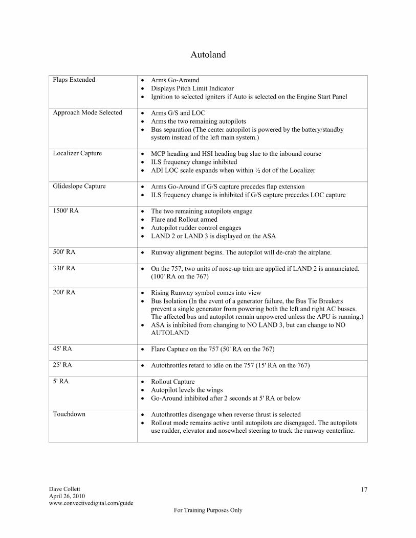
Autoland
Flaps Extended Arms Go-Around Displays Pitch Limit Indicator Ignition to selected igniters if Auto is selected on the Engine Start Panel
Approach Mode Selected Arms G/S and LOC Arms the two remaining autopilots Bus separation (The center autopilot is powered by the battery/standby
system instead of the left main system.)
Localizer Capture MCP heading and HSI heading bug slue to the inbound course ILS frequency change inhibited ADI LOC scale expands when within ½ dot of the Localizer
Glideslope Capture Arms Go-Around if G/S capture precedes flap extension ILS frequency change is inhibited if G/S capture precedes LOC capture
1500' RA The two remaining autopilots engage Flare and Rollout armed Autopilot rudder control engages LAND 2 or LAND 3 is displayed on the ASA
500' RA Runway alignment begins. The autopilot will de-crab the airplane.
330' RA On the 757, two units of nose-up trim are applied if LAND 2 is annunciated. (100' RA on the 767)
200' RA Rising Runway symbol comes into view
Bus Isolation (In the event of a generator failure, the Bus Tie Breakers prevent a single generator from powering both the left and right AC busses. The affected bus and autopilot remain unpowered unless the APU is running.)
ASA is inhibited from changing to NO LAND 3, but can change to NO AUTOLAND
45' RA Flare Capture on the 757 (50' RA on the 767)
25' RA Autothrottles retard to idle on the 757 (15' RA on the 767)
5' RA Rollout Capture
Autopilot levels the wings Go-Around inhibited after 2 seconds at 5' RA or below
Touchdown Autothrottles disengage when reverse thrust is selected Rollout mode remains active until autopilots are disengaged. The autopilots
use rudder, elevator and nosewheel steering to track the runway centerline.
Dave Collett April 26, 2010 www.convectivedigital.com/guide
For Training Purposes Only
18
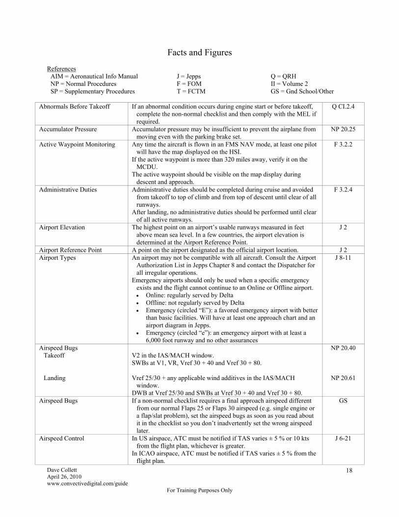
Facts and Figures References
AIM = Aeronautical Info Manual J = Jepps Q = QRH NP = Normal Procedures F = FOM II = Volume 2 SP = Supplementary Procedures T = FCTM GS = Gnd School/Other
Abnormals Before Takeoff If an abnormal condition occurs during engine start or before takeoff,
complete the non-normal checklist and then comply with the MEL if required.
Q CI.2.4
Accumulator Pressure Accumulator pressure may be insufficient to prevent the airplane from moving even with the parking brake set.
NP 20.25
Active Waypoint Monitoring Any time the aircraft is flown in an FMS NAV mode, at least one pilot will have the map displayed on the HSI.
If the active waypoint is more than 320 miles away, verify it on the MCDU.
The active waypoint should be visible on the map display during descent and approach.
F 3.2.2
Administrative Duties Administrative duties should be completed during cruise and avoided from takeoff to top of climb and from top of descent until clear of all runways.
After landing, no administrative duties should be performed until clear of all active runways.
F 3.2.4
Airport Elevation The highest point on an airport’s usable runways measured in feet above mean sea level. In a few countries, the airport elevation is determined at the Airport Reference Point.
J 2
Airport Reference Point A point on the airport designated as the official airport location. J 2 Airport Types An airport may not be compatible with all aircraft. Consult the Airport
Authorization List in Jepps Chapter 8 and contact the Dispatcher for all irregular operations.
Emergency airports should only be used when a specific emergency exists and the flight cannot continue to an Online or Offline airport. Online: regularly served by Delta Offline: not regularly served by Delta Emergency (circled “E”): a favored emergency airport with better
than basic facilities. Will have at least one approach chart and an airport diagram in Jepps.
Emergency (circled “e”): an emergency airport with at least a 6,000 foot runway and no other assurances
J 8-11
Airspeed Bugs Takeoff Landing
V2 in the IAS/MACH window. SWBs at V1, VR, Vref 30 + 40 and Vref 30 + 80. Vref 25/30 + any applicable wind additives in the IAS/MACH
window. DWB at Vref 25/30 and SWBs at Vref 30 + 40 and Vref 30 + 80.
NP 20.40
NP 20.61
Airspeed Bugs If a non-normal checklist requires a final approach airspeed different from our normal Flaps 25 or Flaps 30 airspeed (e.g. single engine or a flap/slat problem), set the airspeed bugs as soon as you read about it in the checklist so you don’t inadvertently set the wrong airspeed later.
GS
Airspeed Control In US airspace, ATC must be notified if TAS varies ± 5 % or 10 kts from the flight plan, whichever is greater.
In ICAO airspace, ATC must be notified if TAS varies ± 5 % from the flight plan.
J 6-21

Dave Collett April 26, 2010 www.convectivedigital.com/guide
For Training Purposes Only
19
Airspeed Limits (U.S.) 250 KIAS below 10,000' MSL within 12 nm of the coastline. 200 KIAS, or minimum speed if greater than 200 knots, at or below
2,500' AGL within 4 nm of the primary airport in Class C or D airspace unless otherwise authorized or required by ATC.
200 KIAS or clean speed or minimum speed, whichever is greater, below Class B airspace or in a Class B VFR corridor.
J 11-NA-27
Airway Course For airways, the displayed FMS course may not be identical to the charted value.
SP 11.20
Airway Width In Class I airspace, the airway includes 4 nm either side of centerline. In Class II airspace, the airway includes 15 nm either side of
centerline. Excursion beyond airway limits is considered a gross navigational
error.
J 7-10
Aisle Stand Do not place items between the pilot seat and the aisle stand because injury may occur when the seat is adjusted.
NP 20.37
Alternate Airport Estimate Enter the alternate as the Destination on Progress page 1. Estimates are for present position direct. Use the Delete key to remove.
SP 11.19
Alternate Airport Required After Takeoff
FAR 121 does not prohibit a flight from continuing to its destination without an alternate once the flight has departed and weather conditions deteriorate to the point where an alternate would have been required for dispatch. The Captain and Dispatcher should discuss the situation and agree to continue to the destination however.
F 5.1.7
Alternate Airport Selected While Airborne
When selecting an alternate airport while airborne, the weather must be at or above normal destination weather minimums. Dispatch alternate weather minimums do not apply.
F 10.2.1
Alternate Airport Weather Minimums
Weather minimums for filing alternates are derived using the Alternate Airport Minimums Tables in Jepps Chapter 2.
If there is no applicable IFR approach, forecast ceiling and visibility must permit a descent from the MEA to land under VFR.
F 5.1.8
Anti-Ice Icing Conditions
Icing conditions exist when OAT (on the ground) or TAT (in flight) is
10°C or below and: visible moisture (clouds, fog with visibility less than 1 statute
mile (1600 m) rain, snow, sleet, ice crystals, etc.) is present, or standing water, ice or snow is present on the ramps, taxiways or
runways
SP 16.1
Dave Collett April 26, 2010 www.convectivedigital.com/guide
For Training Purposes Only
20
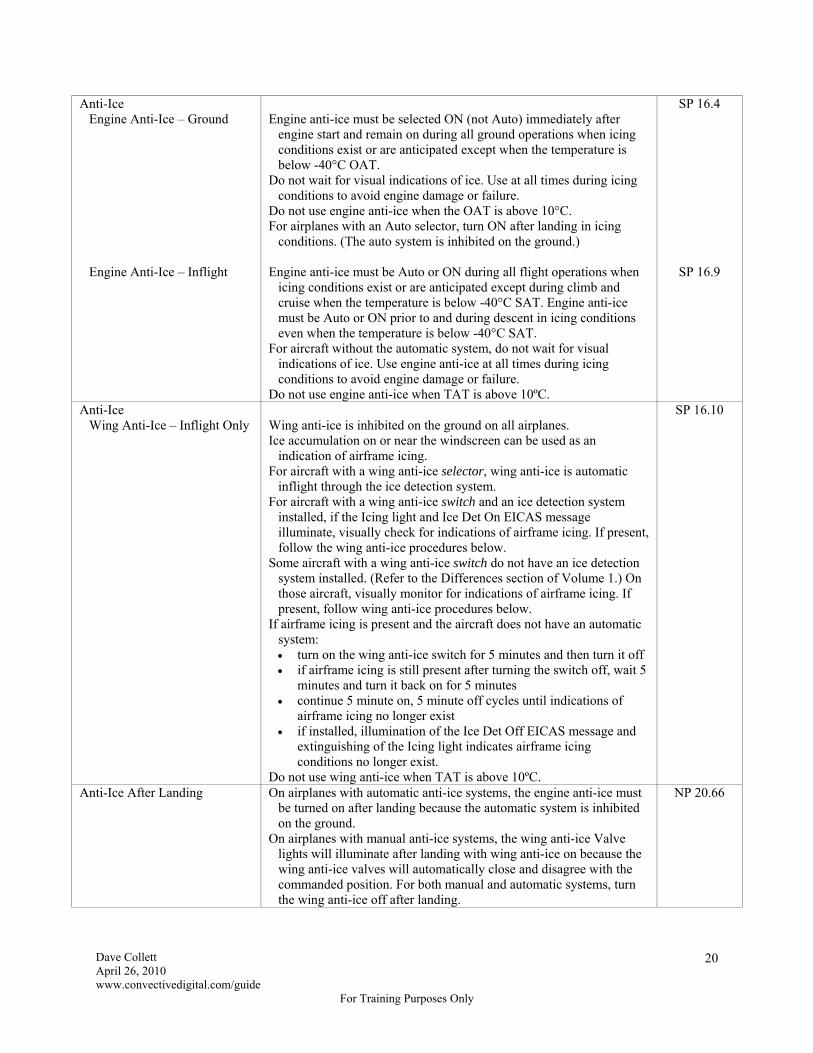
Anti-Ice Engine Anti-Ice – Ground Engine Anti-Ice – Inflight
Engine anti-ice must be selected ON (not Auto) immediately after
engine start and remain on during all ground operations when icing conditions exist or are anticipated except when the temperature is below -40°C OAT.
Do not wait for visual indications of ice. Use at all times during icing conditions to avoid engine damage or failure.
Do not use engine anti-ice when the OAT is above 10°C. For airplanes with an Auto selector, turn ON after landing in icing
conditions. (The auto system is inhibited on the ground.) Engine anti-ice must be Auto or ON during all flight operations when
icing conditions exist or are anticipated except during climb and cruise when the temperature is below -40°C SAT. Engine anti-ice must be Auto or ON prior to and during descent in icing conditions even when the temperature is below -40°C SAT.
For aircraft without the automatic system, do not wait for visual indications of ice. Use engine anti-ice at all times during icing conditions to avoid engine damage or failure.
Do not use engine anti-ice when TAT is above 10ºC.
SP 16.4
SP 16.9
Anti-Ice Wing Anti-Ice – Inflight Only
Wing anti-ice is inhibited on the ground on all airplanes. Ice accumulation on or near the windscreen can be used as an
indication of airframe icing. For aircraft with a wing anti-ice selector, wing anti-ice is automatic
inflight through the ice detection system. For aircraft with a wing anti-ice switch and an ice detection system
installed, if the Icing light and Ice Det On EICAS message illuminate, visually check for indications of airframe icing. If present, follow the wing anti-ice procedures below.
Some aircraft with a wing anti-ice switch do not have an ice detection system installed. (Refer to the Differences section of Volume 1.) On those aircraft, visually monitor for indications of airframe icing. If present, follow wing anti-ice procedures below.
If airframe icing is present and the aircraft does not have an automatic system: turn on the wing anti-ice switch for 5 minutes and then turn it off if airframe icing is still present after turning the switch off, wait 5
minutes and turn it back on for 5 minutes continue 5 minute on, 5 minute off cycles until indications of
airframe icing no longer exist if installed, illumination of the Ice Det Off EICAS message and
extinguishing of the Icing light indicates airframe icing conditions no longer exist.
Do not use wing anti-ice when TAT is above 10ºC.
SP 16.10
Anti-Ice After Landing On airplanes with automatic anti-ice systems, the engine anti-ice must be turned on after landing because the automatic system is inhibited on the ground.
On airplanes with manual anti-ice systems, the wing anti-ice Valve lights will illuminate after landing with wing anti-ice on because the wing anti-ice valves will automatically close and disagree with the commanded position. For both manual and automatic systems, turn the wing anti-ice off after landing.
NP 20.66
Dave Collett April 26, 2010 www.convectivedigital.com/guide
For Training Purposes Only
21
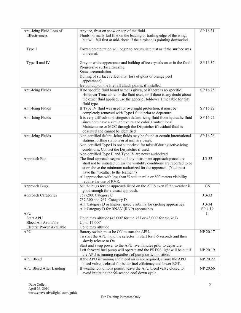
Anti-Icing Fluid Loss of Effectiveness
Type I Type II and IV
Any ice, frost on snow on top of the fluid. Fluids normally fail first on the leading or trailing edge of the wing,
but will fail first at mid-chord if the airplane is pointing downwind. Frozen precipitation will begin to accumulate just as if the surface was
untreated. Gray or white appearance and buildup of ice crystals on or in the fluid. Progressive surface freezing. Snow accumulation. Dulling of surface reflectivity (loss of gloss or orange peel
appearance). Ice buildup on the life raft attach points, if installed.
SP 16.31
SP 16.32
Anti-Icing Fluids If no specific fluid brand name is given, or if there is no specific Holdover Time table for the fluid used, or if there is any doubt about the exact fluid applied, use the generic Holdover Time table for that fluid type.
SP 16.25
Anti-Icing Fluids If Type IV fluid was used for overnight protection, it must be completely removed with Type I fluid prior to departure.
SP 16.22
Anti-Icing Fluids It is very difficult to distinguish de/anti-icing fluid from hydraulic fluid since both have a similar texture and color. Contact local Maintenance or MCC through the Dispatcher if residual fluid is observed and cannot be identified.
SP 16.27
Anti-Icing Fluids Non-certified de/anti-icing fluids may be found at certain international stations, offline stations or at military bases.
Non-certified Type I is not authorized for takeoff during active icing conditions. Contact the Dispatcher if used.
Non-certified Type II and Type IV are never authorized.
SP 16.26
Approach Ban The final approach segment of any instrument approach procedure shall not be initiated unless the visibility conditions are reported to be at or above the minimum authorized for the approach. (You must have the “weather to the feather.”)
All approaches with less than ½ statute mile or 800 meters visibility require the use of RVR.
J 3-32
Approach Bugs Set the bugs for the approach listed on the ATIS even if the weather is good enough for a visual approach.
GS
Approach Categories 757-200: Category C 757-300 and 767: Category D All: Category D or highest speed visibility for circling approaches All: Category D for RNAV (RNP) approaches
J 3-33
J 3-34 SP 4.19
APU Start APU Bleed Air Available Electric Power Available
Up to max altitude (42,000' for the 757 or 43,000' for the 767) Up to 17,000' Up to max altitude
II
APU Battery switch must be ON to start the APU. To start the APU, hold the selector in Start for 3-5 seconds and then
slowly release to On. Start and swap power to the APU five minutes prior to departure. Left forward fuel pump will operate and the PRESS light will be out if
the APU is running regardless of pump switch position.
NP 20.17
NP 20.19
APU Bleed If the APU is running and bleed air is not required, ensure the APU bleed valve is closed for better fuel efficiency and lower EGT.
NP 20.22
APU Bleed After Landing If weather conditions permit, leave the APU bleed valve closed to avoid initiating the 90-second cool down cycle.
NP 20.66

Dave Collett April 26, 2010 www.convectivedigital.com/guide
For Training Purposes Only
22
APU Inop for Pushback If the APU is inop and an engine was started at the gate with external power, the rampers will be unable to open the forward or aft cargo doors to load late bags after pushback because the Ground Handling bus will be unpowered. The Ground Handling bus can only be powered on the ground by either external power or the APU. The bulk cargo door on the 767 can be opened manually however.
II
APU Leaks There should be no leaks from the APU exhaust or drains. NP 20.11 APU On Electrical Power Down Turn the APU selector off and wait until the Run light extinguishes
before turning off Standby Power and the battery. SP 6.3
APU Policy Flight crews should start the APU approximately 5 minutes prior to pushback for all flights unless pre-conditioned air is unavailable or passenger comfort is affected.
Upon arrival, flight crews should time the APU start so the APU reaches operating speed just prior to the aircraft coming to a stop at the gate. (Approximately 1 minute prior to gate arrival.)
The Captain should not depart the airplane with the APU running unless all attempts to connect ground power have failed.
On terminating flights, flight crews should run the Secure checklist and shut down the APU. A terminating flight is defined as the aircraft remaining at the gate more than 2 hours from block-in to block-out time. If ground power is not available, the crew will leave a dark aircraft.
F 3.4.2
APU Starter Duty Cycle 3 start attempts within a 60-minute period. NP 20.17 Assumed Temperature Takeoffs Do not use Assumed Temperature (reduced thrust) when:
restricted at particular airports by the Delta Special Pages unstable weather conditions exist AWABS is inop
NP 20.38
Assumed Temperature Takeoffs Reduced thrust takeoffs are allowed after de/anti-icing provided takeoff performance accounts for the runway surface condition.
SP 16.7
Assumed Temperature Takeoffs Takeoff thrust cannot be less than climb thrust, so in some cases it may be necessary to reduce climb thrust in order to enter a high assumed temperature for a low takeoff thrust.
If the FMS will not accept the desired assumed temperature for takeoff, select CLB 1 and re-enter the assumed temperature. If the FMS still will not accept the desired assumed temperature, select CLB 2 and re-enter. If the FMS still will not accept the assumed temperature, use a higher assumed temperature from the AWABS.
If CLB 1 or CLB 2 was selected prior to takeoff, it should be removed during initial climb. After climb power is selected, push the 1 or 2, as appropriate, on the TMSP to remove the climb derate and select full climb power.
SP 7.4
Attila Any ATC clearance that conflicts with an Attila RTA take precedence and nullify the RTA.
In general, a 0.01 Mach change in airspeed will change a fix ETA by one minute per hour.
On Pegasus airplanes enter the RTA fix and time on Progress page 3.
SP 5.37
Attila Attila should not require a speed change in excess of 5% or 10 knots, eliminating the need to notify ATC.
F 3.4.3
Auto Speedbrake Inop Deploying the speedbrakes manually before nosewheel touchdown on landing may cause a pronounced nose pitch up.
Q 9.4
Autobrake Selection Autobrake selection for landing is “as desired.” NP 20.60
Dave Collett April 26, 2010 www.convectivedigital.com/guide
For Training Purposes Only
23
Autobrakes on Landing Autobrakes on RTO Disarming Autobrakes
(F-STOP) Speedbrakes on RTO Speedbrakes on Landing Armed Not Armed
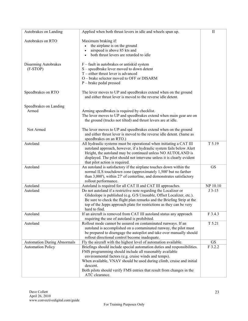
Applied when both thrust levers in idle and wheels spun up. Maximum braking if: the airplane is on the ground airspeed is above 85 kts and both thrust levers are retarded to idle
F – fault in autobrakes or antiskid system S – speedbrake lever moved to down detent T – either thrust lever is advanced O – brake selector moved to OFF or DISARM P – brake pedal pressed The lever moves to UP and speedbrakes extend when on the ground
and either thrust lever is moved to the reverse idle detent. Arming speedbrakes is required by checklist. The lever moves to UP and speedbrakes extend when main gear are on
the ground (trucks not tilted) and thrust levers are at idle. The lever moves to UP and speedbrakes extend when on the ground
and either thrust lever is moved to the reverse idle detent. (Same as speedbrakes on an RTO.)
II
Autoland All hydraulic systems must be operational when initiating a CAT III autoland approach, however, if a hydraulic system fails below Alert Height, the autoland may be continued unless NO AUTOLAND is displayed. The pilot should not intervene unless it is clearly evident that pilot action is required.
T 5.19
Autoland An autoland is satisfactory if the airplane touches down within the normal ILS touchdown zone (approximately 1,500' but no farther than 3,000'), within 27' of centerline, and demonstrates satisfactory rollout performance.
GS
Autoland Autoland is required for all CAT II and CAT III approaches. NP 10.10 Autoland Do not autoland if a restrictive note regarding the Localizer or
Glideslope is published (e.g. G/S Unusable, Offset Localizer, etc.). Be sure to check the flight plan remarks and the Briefing Strip at the top of the Jepps approach plate for restrictions as they can be very hard to find.
J 3-15
Autoland If an aircraft is removed from CAT III autoland status any approach requiring the use of autoland is prohibited.
F 3.4.3
Autoland Rollout mode cannot be assured on contaminated runways. If an autoland is accomplished on a contaminated runway, the pilot must be prepared to disengage the autopilot and take over manually should rollout directional control become inadequate.
T 5.21
Automation During Abnormals Fly the aircraft with the highest level of automation available. GS Automation Policy Briefings should include special automation duties and responsibilities.
FMS programming should include all reasonably available environmental factors (e.g. cruise winds and temps).
When available, VNAV should be used during climb, cruise and initial descent.
Both pilots should verify FMS entries that result from changes in the ATC clearance.
F 3.2.2

Dave Collett April 26, 2010 www.convectivedigital.com/guide
For Training Purposes Only
24
Autopilot and Autothrottles When Not Autolanding
Autopilot on an ILS Autopilot on a Non-ILS Autothrottles
Disconnect prior to the flare. Disconnect no later than MDA/DA - 50' or DDA - 100'. Disconnect prior to the flare or prior to the End-of-Descent point when
using VNAV on non-Pegasus (non-GPS) airplanes.
NP 30.19
Autopilot and Flight Director Required
If operable, both the autopilot and flight director will be used for all ILS approaches when the weather is below RVR 4000 or ¾ mile.
NP 10.10
Autopilot Engagement If the autopilot is desired after takeoff, it is normally engaged after a roll mode and VNAV are selected.
NP 30.16
Autopilot Engagement The autopilot will not engage in either Takeoff or Go-Around mode. If the flight director is in either of these modes and an autopilot is engaged, the autopilot will engage in Vertical Speed and Heading Hold.
II
Autopilot Rudder Control During a multiple-autopilot approach and go-around, the autopilots control the rudder. If on single engine, be prepared to manually apply rudder at the first change of either pitch or roll mode or if the autopilots are disengaged because the rudder will quickly move to its trimmed position and the airplane will roll abruptly.
II
Autopilot, Flight Director and FMS Monitoring
When a mode change is selected or scheduled to occur, the annunciation must be verified on the flight mode annunciation display (scoreboard).
When a thrust reference mode change is selected or scheduled to occur, the annunciation must be verified on the EICAS display.
NP 10.3
Autopilots Required for Autoland
Two (Three required for a CAT III approach). II
Autothrottle Speed Mode In some cases, selecting SPD mode will result in the Vertical Speed window opening and a possible climb or descent away from the selected altitude.
SP 4.5
AWABS It is permissible to relinquish the FDRA and close the cabin door prior to receiving the WDR uplink, but crews must be in possession of both the WDR and the Preface prior to pushback.
If the gate is staffed by more than one agent, the final passenger count may not be known by the agent collecting the FDRA.
F 5.6.1
AWABS Adjustments When needed to increase takeoff performance weight margin, the actual takeoff weight may be reduced by any unused add-on tolerance.
Positive passenger tolerance can be added in any combination to either class or negative passenger tolerance can be subtracted in any combination from either class.
Positive passenger tolerance may be used to account for both cockpit and cabin jumpseat riders. Personnel authorized to sit on the flight deck jumpseat will count as two passengers and personnel not authorized to sit on the flight deck jumpseat will count as one passenger.
Negative passenger tolerance may not be used to remove a jumpseat rider listed as JS on the AWABS. A corrected AWABS is required.
No changes are required if a flight deck or cabin jumpseat rider moves to an open seat in the cabin.
Cargo tolerance is positive only. You cannot subtract cargo. Do not use positive cargo tolerance if negative passenger tolerance was used.
F 5.6.3

Dave Collett April 26, 2010 www.convectivedigital.com/guide
For Training Purposes Only
25
AWABS Corrections Make AWABS corrections in the following order: 1. use tolerances and/or performance notes 2. request an AWABS update via ACARS 3. request a new AWABS if it will not delay departure 4. contact Flight Control
F 5.6.10
AWABS Headwinds and Tailwinds
HW xx is the minimum headwind component required for takeoff. TW xx is the maximum tailwind component already included in the
performance calculations.
F 5.6.5
AWABS Remote Command Processor
The AWABS Remote Command Processor can be used only after the initial WDR is produced.
The codes for all authorized takeoff positions are listed on the WDR Preface, but these codes can also be obtained via uplink by requesting takeoff data for a runway that does not exist, such as Runway 36 in ATL (e.g. enter “88/36/D”).
F 5.6.10
F 5.6.11
Backcourse Localizer Always press B/CRS before pressing LOC. SP 4.11 Bank Limit Selector If the Bank Limit Selector is other than Auto, excessive bank angle
may occur in HDG SEL at high altitudes or airspeeds. NP 20.22
Basic Turbojet Minimums Not less than RVR 4000 (1200 m) or ¾ statute mile visibility and 200' DH or 250' MDH.
J 3-32
Battery Power The battery will last approximately 30 minutes. Flight beyond 30 minutes will result in complete loss of electrical power. On the 767 it will also result in the inability to extend the landing gear and flaps.
Q 6.5
Below Glideslope Alert May be cancelled or inhibited for: localizer or backcourse localizer approach circling from an ILS when conditions require a deliberate approach below G/S unreliable glideslope signal visual contact with the ground during day VMC
Q Man.1.8
Blended Winglet Cost Index During FMS preflight loading, initially enter the Cost Index from the Dispatcher Remarks section of the flight plan. All subsequent changes to the Cost Index must be derived from the ODM.
NP 20.31
Brake Source Light Indicates both normal and alternate brake source pressures are low. If it remains illuminated after selecting Reserve Brakes on the 757 or Reserve Brakes and Steering on the 767, the reserve brakes are still unpressurized and only accumulator braking is available.
II
Brake System Hydraulics 757 (“Right-Left-Right”) 767 (“Royal Crown Cola”)
Normal – Right Alternate – Left (automatic if right hyd system press low) Reserve – Right (press the RESERVE BRAKES switch) Normal – Right Alternate – Center (automatic if right hyd system press low) Reserve – Center (press RESERVE BKS & STEERING switch)
II
Brake Wear Indicators Must extend out of the guides when the parking brake is set. NP 20.10 Braking Action Advisories When braking conditions are less than “Good,” pilots are expected to
provide a PIREP. When tower controllers receive braking action reports from pilots or
airport management using the terms “fair,” “poor” or “nil,” or whenever weather conditions are conducive to deteriorating or rapidly changing braking conditions, the ATIS will include “Braking action advisories are in effect.”
J 4-72
Braking Action Nil Operations at any airport with a report of nil braking action are prohibited.
J 4-72

Dave Collett April 26, 2010 www.convectivedigital.com/guide
For Training Purposes Only
26
Braking Action Report A braking action report to the tower and the company is required when braking action is less than “Good.” Use ACARS for the report if available.
J 6-46
Briefings Departure Briefing (“Threatening WARTS”) Takeoff Briefing (HAA) Approach Briefing (“Threatening NATS”) Leaving the Cockpit
Brief the highest threat. W - Weather and Winds, including Takeoff Alternate A - Abnormal Procedures and Abort Considerations R - Runway Considerations T – Taxi, Terrain and Transition Altitude if not 18,000 feet S - SID/DP and Special Pages Brief the highest threat. H - Heading A - Altitude and Transition Altitude if not 18,000 feet A - Airspeed Restrictions Brief the highest threat. N - NOTAMS A - Approach Chart and Automation T - Transition Level if not FL180, Terrain and Taxi S - Special Pages If one pilot leaves the cockpit, a briefing will be conducted
summarizing automation status, clearance limits, fuel status, etc. When he returns the PF will brief any relevant changes.
F 3.3.2
F 3.3.3
F 3.3.3
F 3.2.8
Bulk Cargo Heat Selector (767) Keep in the VENT position for transporting animals. NP 20.15 Cabin Altitude Warning Outflow Valve Closes Altitude Warning Resets Passenger Masks Drop Passenger Oxygen Duration
10,000' cabin altitude 11,000' cabin altitude (if cabin controller is in Auto) 8,500' cabin altitude 14,000' cabin altitude 12 minutes (22 minutes on some 757s)
II
Cabin Interphone System Inop Ensure all cabin handsets are properly stowed. Q 5.5 Callouts in Visual Conditions On any approach, if the Pilot Flying can maintain visual contact with
the runway, the “Approaching Minimums” and “Minimums” callouts are not required.
The “1,000, cleared to land/no landing clearance” and “500/Checks” callouts are always required however.
NP 10.12
Callouts on Approaches Callouts at 1,000 feet and 500 feet are always made by reference to the radio altimeter.
The “Approaching Minimums” and “Minimums” callouts are made by reference to whichever altimeter (baro or radio) defines the minimums
NP 10.13
NP 10.15 NP 10.16
Canceling IFR Authorized VFR weather conditions exist. In direct communication with CTAF or other service providing traffic
advisories. Within 10 nm of the airport or in visual contact with the landing
runway that can be maintained until landing. Must cancel IFR with the controlling agency.
J 3-72
Cargo Fire After landing, inform ground personnel not to open any cargo door until all passengers and crew are off and fire-fighting equipment is nearby.
Q 8.20
Cargo Fire Detectors Since the cargo fire detectors detect smoke, the fire-extinguishing agent may cause the detectors to indicate a fire still exists even after it has been extinguished.
II
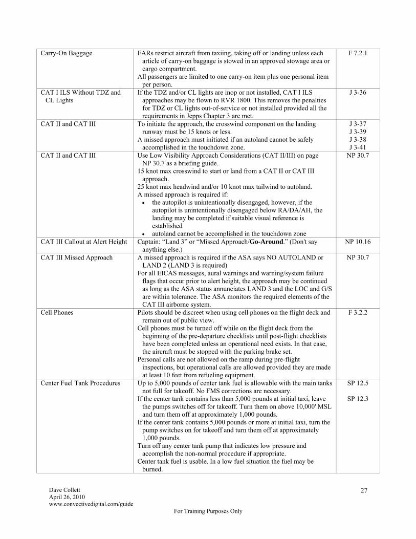
Dave Collett April 26, 2010 www.convectivedigital.com/guide
For Training Purposes Only
27
Carry-On Baggage FARs restrict aircraft from taxiing, taking off or landing unless each article of carry-on baggage is stowed in an approved stowage area or cargo compartment.
All passengers are limited to one carry-on item plus one personal item per person.
F 7.2.1
CAT I ILS Without TDZ and CL Lights
If the TDZ and/or CL lights are inop or not installed, CAT I ILS approaches may be flown to RVR 1800. This removes the penalties for TDZ or CL lights out-of-service or not installed provided all the requirements in Jepps Chapter 3 are met.
J 3-36
CAT II and CAT III To initiate the approach, the crosswind component on the landing runway must be 15 knots or less.
A missed approach must initiated if an autoland cannot be safely accomplished in the touchdown zone.
J 3-37 J 3-39 J 3-38 J 3-41
CAT II and CAT III Use Low Visibility Approach Considerations (CAT II/III) on page NP 30.7 as a briefing guide.
15 knot max crosswind to start or land from a CAT II or CAT III approach.
25 knot max headwind and/or 10 knot max tailwind to autoland. A missed approach is required if: the autopilot is unintentionally disengaged, however, if the
autopilot is unintentionally disengaged below RA/DA/AH, the landing may be completed if suitable visual reference is established
autoland cannot be accomplished in the touchdown zone
NP 30.7
CAT III Callout at Alert Height Captain: “Land 3” or “Missed Approach/Go-Around.” (Don't say anything else.)
NP 10.16
CAT III Missed Approach A missed approach is required if the ASA says NO AUTOLAND or LAND 2 (LAND 3 is required)
For all EICAS messages, aural warnings and warning/system failure flags that occur prior to alert height, the approach may be continued as long as the ASA status annunciates LAND 3 and the LOC and G/S are within tolerance. The ASA monitors the required elements of the CAT III airborne system.
NP 30.7
Cell Phones Pilots should be discreet when using cell phones on the flight deck and remain out of public view.
Cell phones must be turned off while on the flight deck from the beginning of the pre-departure checklists until post-flight checklists have been completed unless an operational need exists. In that case, the aircraft must be stopped with the parking brake set.
Personal calls are not allowed on the ramp during pre-flight inspections, but operational calls are allowed provided they are made at least 10 feet from refueling equipment.
F 3.2.2
Center Fuel Tank Procedures Up to 5,000 pounds of center tank fuel is allowable with the main tanks not full for takeoff. No FMS corrections are necessary.
If the center tank contains less than 5,000 pounds at initial taxi, leave the pumps switches off for takeoff. Turn them on above 10,000' MSL and turn them off at approximately 1,000 pounds.
If the center tank contains 5,000 pounds or more at initial taxi, turn the pump switches on for takeoff and turn them off at approximately 1,000 pounds.
Turn off any center tank pump that indicates low pressure and accomplish the non-normal procedure if appropriate.
Center tank fuel is usable. In a low fuel situation the fuel may be burned.
SP 12.5
SP 12.3

Dave Collett April 26, 2010 www.convectivedigital.com/guide
For Training Purposes Only
28
Chart and Map Utilization For all operations, pilots will have adequate Jeppesen Airway Manual material out of the flight kit and available for immediate reference.
When using a single set of Jepps (e.g. ship set or reroute), both pilots should review the charts, but the pilot flying the approach should have the chart viewable during the approach.
F 3.2.3
Checklist Discipline On the ground, if a checklist item has not been accomplished, the checklist must be stopped until it is accomplished, however the Pushback/Start checklist may be started while awaiting the “Cabin is ready for pushback” report from the Flight Leader.
If all pilots leave the cockpit during or after the Before Start checklist, the entire checklist must be re-accomplished.
Do not start the After Landing checklist until clear of the runway or after the 180º turn during a back taxi.
In flight, if a checklist item has not been accomplished the checklist may be continued and that item listed as “To Go.”
Q CI.1.2
Circling Approaches At FAF and MDA Missed Approach
Gear down. Flaps 20 (Flaps 25/30 optional). Speedbrakes armed. Select landing flaps when turning base if not already selected. Make a climbing turn in the shortest direction toward the landing
runway and then fly the published missed approach for the runway to which the approach was flown.
NP 30.21
Circling Approaches Minimum Visibility Minimum Ceiling MDA
3 sm (4800 m) or CAT D/highest speed visibility, whichever is higher. 1,000' or CAT D/highest speed HAA, whichever is higher. 1,000' HAA or CAT D/highest speed MDA, whichever is higher.
J 3-34
Circling Area Radius 2.3 nm from the runway thresholds at 165 kts max for CAT D. T 5.60 Circling from an ILS Use LOC and V/S or VNAV modes. Do not use Approach mode
because Approach mode will not level off at the MCP altitude and exiting Approach mode requires initiating a go-around or disconnecting the autopilot and turning off the flight directors.
T 5.59
Circuit Breaker Reset Do not reset a tripped fuel boost pump circuit breaker. Flight crew reset of a tripped circuit breaker is not recommended
unless directed by a non-normal checklist, however a tripped circuit breaker may be reset once, after a short cooling period, if the situation resulting from the tripped breaker has a significant adverse effect on safety. A reset should only be accomplished after maintenance and the flight crew have determined it is safe to do so.
The flight crew may cycle the circuit breaker(s) of a degraded or inoperative system (normally only one time per event) provided the Captain determines the affected system is desirable for the conduct of the flight and one of the following conditions exists: the breaker had not previously tripped and there is no specific
non-normal procedure in the checklist prohibiting reset (e.g. fuel boost pump), or
maintenance has determined cycling the circuit breaker is safe. If a circuit breaker is cycled during flight, notify maintenance. A
logbook entry shall be made to document the occurrence.
Q CI.2.4
Clean Aircraft Concept Takeoff is prohibited when frost, ice, snow or slush is adhering to the wings, control surfaces, engine inlets or other critical surfaces of the aircraft.
Do not rely on airflow during takeoff roll to remove frozen precipitation that may be adhering to the aircraft.
SP16.17

Dave Collett April 26, 2010 www.convectivedigital.com/guide
For Training Purposes Only
29
Clear of Runway When clearing a runway during low-visibility operations, the tail of the aircraft will be clear of the runway after the fifth taxiway light passes under the nose.
GS
Clearance Awareness The Captain will repeat the taxi clearance after the F/O has read the clearance back to ATC.
Prior to crossing a runway hold short line to either take off from or cross a runway, both pilots should confirm their location by comparing taxiway and runway identification signs to the taxi chart.
Prior to takeoff, both crew members will confirm alignment of the intended departure runway by reference to the HSI.
Prior to departing the last assigned altitude, both pilots should verify the altitude specified in the clearance has been set correctly by stating the altitude and pointing at the altitude display window. Also ensure the proper altimeter reference (QNH or QNE) is set.
The PF should repeat crossing restrictions, headings, airspeeds and clearance limits
To avoid distracting the PM, the PF should avoid repeating clearances or calling for gear or flap changes while the PM is listening to or reading back a clearance.
F 3.2.4
Cleared for Approach When cleared for an approach via a radar vector to a published segment of the approach, maintain the last assigned altitude until intercepting a published segment and then comply with the published altitudes on the approach.
J 3-101
Climb or Descent Direct Executing CLB DIR or DES DIR deletes all waypoint altitude constraints between the airplane’s current altitude and the MCP altitude.
SP 11.25
Coded Departure Routes An abbreviated clearance used at major airports during bad weather. J 11-NA-27 Coded Departure Routes Approved Coded Departure Routes (CDRs) will be listed in the
Supplemental Route Section of the Flight Plan. If a CDR is listed, the Dispatcher is aware of and approves its use.
F 5.3.11
Cold Temperature Altimeter Corrections
If the airport air temperature is -10°C (14°F) or lower, coordinate with ATC and apply the Cold Temperature Altimeter Corrections in Jepps Chapter 4.
Do not apply corrections to the special cold weather approach charts (blue pages). Corrections have already been applied.
Except in Canada, minimum radar vectoring altitudes are not temperature corrected. Request ATC to provide at least 1000 feet above MVA in cold temperature when vectored below MSA or Grid MORA at night or in IMC and terrain clearance cannot be otherwise assured.
In very cold temperatures, altimeter errors can exceed 1,000 feet resulting in potentially unsafe terrain clearance if no corrections are made.
J 4-61
T 1.23
Cold-Soaked Wings Ice or frost on the upper wing surface should be suspected if: frost or ice is observed on the under side of the wing, and the airplane arrived with a large amount of fuel in the wing tanks
Adding warm fuel to the wing tanks is the quickest way to alleviate a cold-soaked wing condition.
SP 16.17
Complaint Resolution Official The Complaint Resolution Official (CRO) is an employee trained in disability regulations. He should be contacted for guidance on any unresolved issues concerning disabled passengers.
F 7.1.4
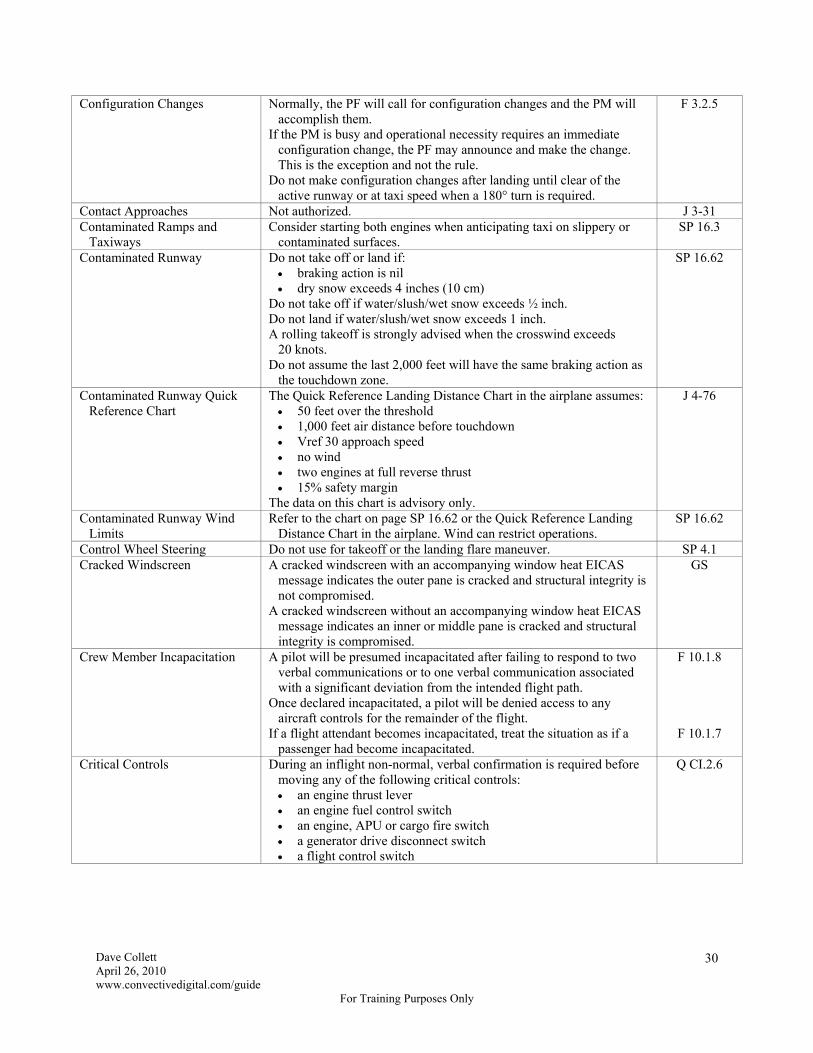
Dave Collett April 26, 2010 www.convectivedigital.com/guide
For Training Purposes Only
30
Configuration Changes Normally, the PF will call for configuration changes and the PM will accomplish them.
If the PM is busy and operational necessity requires an immediate configuration change, the PF may announce and make the change. This is the exception and not the rule.
Do not make configuration changes after landing until clear of the active runway or at taxi speed when a 180° turn is required.
F 3.2.5
Contact Approaches Not authorized. J 3-31 Contaminated Ramps and
Taxiways Consider starting both engines when anticipating taxi on slippery or
contaminated surfaces. SP 16.3
Contaminated Runway Do not take off or land if: braking action is nil dry snow exceeds 4 inches (10 cm)
Do not take off if water/slush/wet snow exceeds ½ inch. Do not land if water/slush/wet snow exceeds 1 inch. A rolling takeoff is strongly advised when the crosswind exceeds
20 knots. Do not assume the last 2,000 feet will have the same braking action as
the touchdown zone.
SP 16.62
Contaminated Runway Quick Reference Chart
The Quick Reference Landing Distance Chart in the airplane assumes: 50 feet over the threshold 1,000 feet air distance before touchdown Vref 30 approach speed no wind two engines at full reverse thrust 15% safety margin
The data on this chart is advisory only.
J 4-76
Contaminated Runway Wind Limits
Refer to the chart on page SP 16.62 or the Quick Reference Landing Distance Chart in the airplane. Wind can restrict operations.
SP 16.62
Control Wheel Steering Do not use for takeoff or the landing flare maneuver. SP 4.1 Cracked Windscreen A cracked windscreen with an accompanying window heat EICAS
message indicates the outer pane is cracked and structural integrity is not compromised.
A cracked windscreen without an accompanying window heat EICAS message indicates an inner or middle pane is cracked and structural integrity is compromised.
GS
Crew Member Incapacitation A pilot will be presumed incapacitated after failing to respond to two verbal communications or to one verbal communication associated with a significant deviation from the intended flight path.
Once declared incapacitated, a pilot will be denied access to any aircraft controls for the remainder of the flight.
If a flight attendant becomes incapacitated, treat the situation as if a passenger had become incapacitated.
F 10.1.8
F 10.1.7
Critical Controls During an inflight non-normal, verbal confirmation is required before moving any of the following critical controls: an engine thrust lever an engine fuel control switch an engine, APU or cargo fire switch a generator drive disconnect switch a flight control switch
Q CI.2.6

Dave Collett April 26, 2010 www.convectivedigital.com/guide
For Training Purposes Only
31
Critical Terrain Technique The following technique can be useful when flying over critical terrain: load the escape route in Route 2 and display it on the Map as
described in SP 11 use the orange bug on the altimeter as a reminder for the direction
of turn. Set 250' for a right turn and 750' for a left turn the PF can set reminders for the initial altitude and airspeed on
his VOR panel. For example, if the initial altitude is 14,000' and the initial airspeed is 310 knots, he can manually set 114.0 as the frequency and 310 as the course and then return the panel to Auto to allow DME-DME updating.
the PM can manually set the appropriate frequency and course for the escape airway on his VOR panel and then also return to Auto
in the event of an emergency descent, the orange bug will point the direction of turn and each pilot can just push Manual on his VOR panel to access reminders for altitude and airspeed and to display a backup for the escape route
airways are 4 nm wide, so use XTK Error to determine when you're on the airway and can continue descent to the minimum altitude
GS
Crosswind Landings During normal operations, Delta pilots are authorized a maximum crosswind limit of 29 knots for takeoff and landing. The airplanes are designed (but not necessarily demonstrated) to higher crosswind limits however. For informational purposes, the max crosswind on wet or dry runways is 40 knots.
T 6.43
Crosswind Landings Sideslip-only (zero crab) landings are not recommended with crosswinds above 28 knots (757-200) or 25 knots (757-300) or 26 kts (767) to avoid scraping a wing or engine on the runway and to maintain adequate control margin.
T 6.43 T 6.44
Cruise and Direct Clearances A “cruise” clearance is a clearance along a published airway that provides a transition to the approach environment. Descent may be initiated at the pilot’s discretion to the applicable minimum IFR altitude along the assigned route of flight. The flight is also cleared for any instrument approach unless restricted by ATC.
A “direct” clearance to an airport or fix is not clearance to descend until on a published segment.
J 3-62
CVR and FDR In flight, the cockpit voice recorder and flight data recorder must remain operative at all times and may not be disabled in flight for any reason.
F 3.4.7
DA and DH DA is Decision Altitude and is determined by reference to the barometric altimeter.
DH is Decision Height and is determined by reference to the radio altimeter.
T 5.9
Dangerous Goods Drill Codes Drill Codes are intended as supplemental guidance and do not replace the appropriate abnormal checklist. Drill Codes are listed on the NOTAC or NOTOC and the corresponding guidance is in the FOM.
F 8.2.2
Departure Clearance If the departure clearance is received via PDC, both pilots should review it.
If the departure clearance is received via radio, both pilots should monitor and confirm the issued clearance.
F 3.2.4
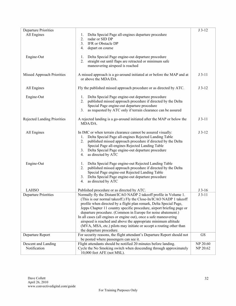
Dave Collett April 26, 2010 www.convectivedigital.com/guide
For Training Purposes Only
32
Departure Priorities All Engines Engine-Out Missed Approach Priorities All Engines Engine-Out Rejected Landing Priorities All Engines Engine-Out LAHSO
1. Delta Special Page all-engines departure procedure 2. radar or SID DP 3. IFR or Obstacle DP 4. depart on course
1. Delta Special Page engine-out departure procedure 2. straight out until flaps are retracted or minimum safe
maneuvering airspeed is reached A missed approach is a go-around initiated at or before the MAP and at
or above the MDA/DA. Fly the published missed approach procedure or as directed by ATC.
1. Delta Special Page engine-out departure procedure 2. published missed approach procedure if directed by the Delta
Special Page engine-out departure procedure 3. as requested by ATC only if terrain clearance can be assured
A rejected landing is a go-around initiated after the MAP or below the
MDA/DA. In IMC or when terrain clearance cannot be assured visually:
1. Delta Special Page all-engines Rejected Landing Table 2. published missed approach procedure if directed by the Delta
Special Page all-engines Rejected Landing Table 3. Delta Special Page engine-out departure procedure 4. as directed by ATC
1. Delta Special Page engine-out Rejected Landing Table 2. published missed approach procedure if directed by the Delta
Special Page engine-out Rejected Landing Table 3. Delta Special Page engine-out departure procedure 4. as directed by ATC
Published procedure or as directed by ATC.
J 3-12
J 3-11
J 3-12
J 3-11
J 3-12
J 3-16 Departure Priorities Normally fly the Distant/ICAO NADP 2 takeoff profile in Volume 1.
(This is our normal takeoff.) Fly the Close-In/ICAO NADP 1 takeoff profile when directed by a flight plan remark, Delta Special Page, Jepps Chapter 11 country specific procedure, airport briefing page or departure procedure. (Common in Europe for noise abatement.)
In all cases (all engines or engine out), once a safe maneuvering airspeed is reached and above the appropriate minimum altitude (MVA, MSA, etc.) pilots may initiate or accept a routing other than the departure procedure.
J 3-11
Departure Report For security reasons, the flight attendant’s Departure Report should not be posted where passengers can see it.
GS
Descent and Landing Notification
Flight attendants should be notified 20 minutes before landing. Cycle the No Smoking switch when descending through approximately
10,000 feet AFE (not MSL).
NP 20.60 NP 20.62
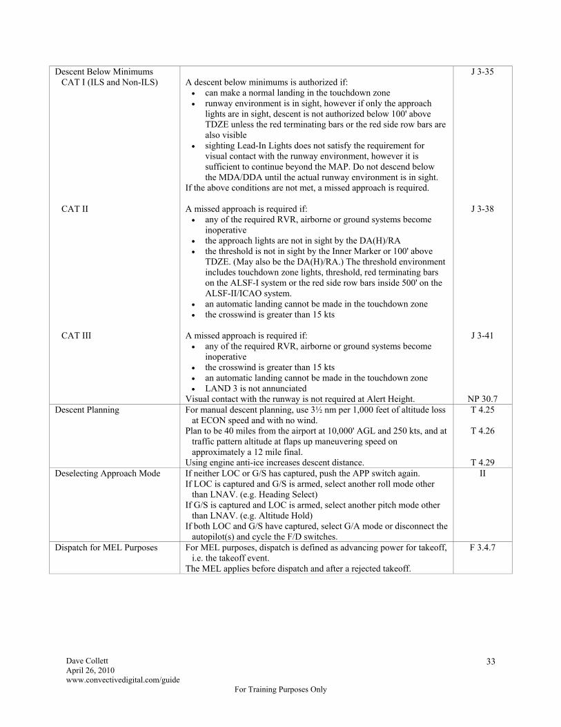
Dave Collett April 26, 2010 www.convectivedigital.com/guide
For Training Purposes Only
33
Descent Below Minimums CAT I (ILS and Non-ILS) CAT II CAT III
A descent below minimums is authorized if: can make a normal landing in the touchdown zone runway environment is in sight, however if only the approach
lights are in sight, descent is not authorized below 100' above TDZE unless the red terminating bars or the red side row bars are also visible
sighting Lead-In Lights does not satisfy the requirement for visual contact with the runway environment, however it is sufficient to continue beyond the MAP. Do not descend below the MDA/DDA until the actual runway environment is in sight.
If the above conditions are not met, a missed approach is required. A missed approach is required if: any of the required RVR, airborne or ground systems become
inoperative the approach lights are not in sight by the DA(H)/RA the threshold is not in sight by the Inner Marker or 100' above
TDZE. (May also be the DA(H)/RA.) The threshold environment includes touchdown zone lights, threshold, red terminating bars on the ALSF-I system or the red side row bars inside 500' on the ALSF-II/ICAO system.
an automatic landing cannot be made in the touchdown zone the crosswind is greater than 15 kts
A missed approach is required if: any of the required RVR, airborne or ground systems become
inoperative the crosswind is greater than 15 kts an automatic landing cannot be made in the touchdown zone LAND 3 is not annunciated
Visual contact with the runway is not required at Alert Height.
J 3-35
J 3-38
J 3-41
NP 30.7 Descent Planning For manual descent planning, use 3½ nm per 1,000 feet of altitude loss
at ECON speed and with no wind. Plan to be 40 miles from the airport at 10,000' AGL and 250 kts, and at
traffic pattern altitude at flaps up maneuvering speed on approximately a 12 mile final.
Using engine anti-ice increases descent distance.
T 4.25
T 4.26
T 4.29 Deselecting Approach Mode If neither LOC or G/S has captured, push the APP switch again.
If LOC is captured and G/S is armed, select another roll mode other than LNAV. (e.g. Heading Select)
If G/S is captured and LOC is armed, select another pitch mode other than LNAV. (e.g. Altitude Hold)
If both LOC and G/S have captured, select G/A mode or disconnect the autopilot(s) and cycle the F/D switches.
II
Dispatch for MEL Purposes For MEL purposes, dispatch is defined as advancing power for takeoff, i.e. the takeoff event.
The MEL applies before dispatch and after a rejected takeoff.
F 3.4.7
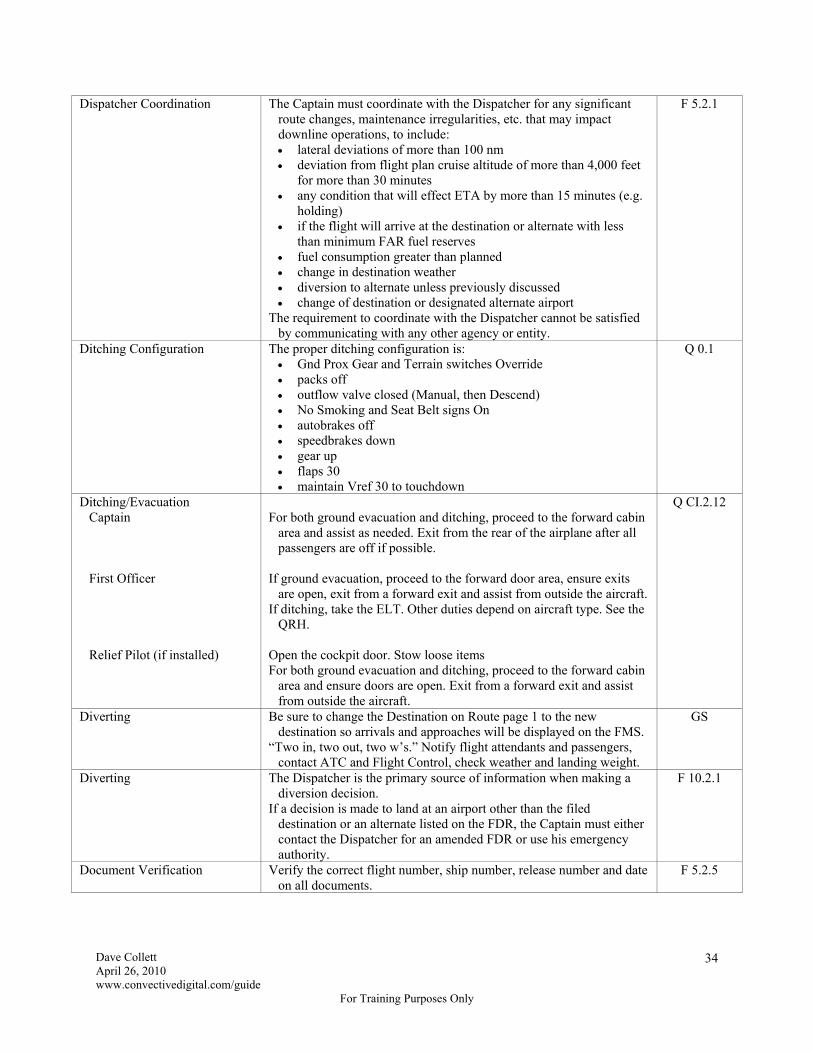
Dave Collett April 26, 2010 www.convectivedigital.com/guide
For Training Purposes Only
34
Dispatcher Coordination The Captain must coordinate with the Dispatcher for any significant route changes, maintenance irregularities, etc. that may impact downline operations, to include: lateral deviations of more than 100 nm deviation from flight plan cruise altitude of more than 4,000 feet
for more than 30 minutes any condition that will effect ETA by more than 15 minutes (e.g.
holding) if the flight will arrive at the destination or alternate with less
than minimum FAR fuel reserves fuel consumption greater than planned change in destination weather diversion to alternate unless previously discussed change of destination or designated alternate airport
The requirement to coordinate with the Dispatcher cannot be satisfied by communicating with any other agency or entity.
F 5.2.1
Ditching Configuration The proper ditching configuration is: Gnd Prox Gear and Terrain switches Override packs off outflow valve closed (Manual, then Descend) No Smoking and Seat Belt signs On autobrakes off speedbrakes down gear up flaps 30 maintain Vref 30 to touchdown
Q 0.1
Ditching/Evacuation Captain First Officer Relief Pilot (if installed)
For both ground evacuation and ditching, proceed to the forward cabin
area and assist as needed. Exit from the rear of the airplane after all passengers are off if possible.
If ground evacuation, proceed to the forward door area, ensure exits
are open, exit from a forward exit and assist from outside the aircraft. If ditching, take the ELT. Other duties depend on aircraft type. See the
QRH. Open the cockpit door. Stow loose items For both ground evacuation and ditching, proceed to the forward cabin
area and ensure doors are open. Exit from a forward exit and assist from outside the aircraft.
Q CI.2.12
Diverting Be sure to change the Destination on Route page 1 to the new destination so arrivals and approaches will be displayed on the FMS.
“Two in, two out, two w’s.” Notify flight attendants and passengers, contact ATC and Flight Control, check weather and landing weight.
GS
Diverting The Dispatcher is the primary source of information when making a diversion decision.
If a decision is made to land at an airport other than the filed destination or an alternate listed on the FDR, the Captain must either contact the Dispatcher for an amended FDR or use his emergency authority.
F 10.2.1
Document Verification Verify the correct flight number, ship number, release number and date on all documents.
F 5.2.5

Dave Collett April 26, 2010 www.convectivedigital.com/guide
For Training Purposes Only
35
Dry Microburst Conditions Be alert for dry microbursts in the following conditions: surface temperature above 75°F dew point spread of 30° to 50°F convective activity in the area with high cloud bases virga or scattered light rain radar returns of weak cells from 5,000' to 15,000' AGL
GS
Duct Leak (767 Only) Flight longer than 6 hours with a Bleed Duct Leak or a Body Duct Leak light illuminated may result in structural damage.
Q 2.4
EICAS Messages After dispatch (thrust levers advanced for takeoff), it is not required to check status messages because any message concerning the safe continuation of the flight will appear as an EICAS alert message (warning, caution or advisory). On some 757s, however, the only indication of impending fuel filter bypass will be a status message, so look at them anyway.
During engine start and prior to takeoff, any alert message requires the appropriate non-normal procedure followed by checking the MEL. The MEL must be checked prior to takeoff.
Check status messages after shutdown and record in the logbook. Do not attempt to erase these messages.
NP 10.2
NP 20.71
EICAS Messages Cancel EICAS messages after completing the appropriate abnormal checklist.
GS
EICAS Status Messages Attempt to erase all status messages that appear prior to dispatch. If a status message cannot be erased, contact Maintenance. Do not erase status messages that appear after dispatch. Inform
Maintenance and record in the logbook. To erase status messages, accomplish the following on the auxiliary
panel: 1. press the ECS/MSG switch 2. press the AUTO EVENT READ switch 3. press and hold the ERASE switch for 3 seconds
SP 15.1
Electrical Outlets The 115-volt outlets on the aircraft may not be used to power or charge any personal electronic devices.
F 7.1.9
Electronic Equipment The following electronic equipment is installed: 1 ADF (two on the 767ER) 2 Air Data Computers (ADC) 3 Autopilots 2 DMEs 2 EICAS Computers 3 Flight Control Computers (FCC) 2 Flight Management Computers (FMC) 2 GPSs (if installed) 3 ILSs 3 Inertial Reference Units (IRU) 1 Marker Beacon Receiver 2 Multi-Purpose Control Display Units (MCDU) 3 Radio Altimeters 3 Symbol Generators 1 Thrust Management Computer (TMC) 2 Transponders 2 VORs
II
Emergency Briefing The Captain should brief the Flight Leader on the following (TTSR): T – type of emergency T – time available for cabin preparation S – special instructions (signal to brace/evacuate, usable exits, etc.) R – repeat the information back to the Captain
F 10.1.3

Dave Collett April 26, 2010 www.convectivedigital.com/guide
For Training Purposes Only
36
Emergency Communications Notify: flight attendants passengers “Two In, Two Out” ATC Flight Control
F 10.1.2
Emergency Declaration Guidelines
Red Emergency – the Captain believes circumstances may lead to personnel injury or aircraft damage. A red emergency requires special handling by ATC, fire trucks, and the flight attendants to prepare the cabin for an emergency landing/ditching and evacuation.
Yellow Emergency – an emergency is declared but the safety of the aircraft or passengers is not deemed to be in peril and the Captain expects a successful landing. Fire trucks may or may not be required and the flight attendants will not prepare the cabin for an emergency landing.
Medical Emergency – there is a death, injury or illness on board. A medical emergency must be declared if priority handling is requested from ATC.
If an emergency is declared, the Captain must submit an ASR within 24 hours of returning to base. (There are plenty of other things that require an ASR too. See FOM chapter 11.)
Do not use the terms red or yellow emergency with ATC.
F 10.1.2
F 10.1.1
Emergency Landing Preparation If circumstances permit, the Captain will notify the Dispatcher of the time, place and reason for the intended landing.
Direct the flight attendants to take appropriate precautions for the passengers.
Loosen ties and remove sharp objects. Notify the tower and fire department of the location and type of any
dangerous goods. For an overweight landing, refer to the QRH and the FOM. If a forced landing appears imminent and the aircraft is below
1,000 feet AGL, announce “Brace for landing” over the PA.
F 10.1.4
Emergency Lights Emergency lights must be armed for taxi, takeoff and landing. They do not need to be armed during passenger boarding or deplaning.
F 3.4.5
Emergency Medical Equipment The Captain has final authority in the decision to release medical equipment. If a sealed kit or medical equipment is opened and used: contact UPMC enter a description of the circumstances and the name of the
person authorized to use the kit in the aircraft logbook contact Flight Control to coordinate a replacement
The Enhanced Emergency Medical Kit may be released to individuals possessing medical licenses, certificates or other identification. The Captain may also release it to other individuals who appear to have the necessary medical knowledge or skills.
F 7.4.3
F 7.4.4
Emergency Signal Three distinct soundings of the flight attendant call system. Repeat as necessary.
F 10.1.3
ENG STATOR Message On the 757, the L or R ENG STATOR EICAS messages indicates the EEC is unable to control the stator vane actuator. Any thrust lever movement or changes to anti-ice, air conditioning pack or recirc fan configuration may cause engine flameout. If the EICAS message remains, restart is not possible.
II
Engine Battery Start There is a procedure in SP 7 for starting an engine from the ship’s battery if electrical power from the APU or external power is not available.
SP 7.1

Dave Collett April 26, 2010 www.convectivedigital.com/guide
For Training Purposes Only
37
Engine Compressor Surge or Stall
If an engine compressor surge or stall occurs during ground ops or if a takeoff is rejected due to a compressor surge or stall, a maintenance inspection is required before flight.
F 3.4.9
Engine Control Panel Position the Ignition Selector to 1 for the Captain’s leg and 2 for the First Officer’s leg. Select Single for GE FADEC engines.
NP 20.18
Engine Crossbleed Start The APU must be shut down or the APU bleed switch must be OFF. The area behind the airplane should be considered, but crossbleed
thrust is usually less than breakaway thrust for single-engine taxi. Advance the operating engine to approximately 70% N2.
SP 7.3
Engine Exceedance on Takeoff If an engine exceedance occurs on takeoff after thrust is set and the takeoff is continued, do not retard the thrust lever in an attempt to control the exceedance because it invalidates takeoff performance. Wait until at least 400' AGL and airspeed is acceptable before retarding the thrust lever and accomplishing any required checklist.
T 3.6
Engine Failure (Dual Engine) Do not delay. Accomplish the Dual Engine Failure memory items and establish the appropriate airspeed immediately to take advantage of high engine RPM and improve the chances of a successful restart.
Attempt a windmill restart using memory procedures before starting the APU. If a windmill restart is not successful, start the APU as soon as practical to provide power for subsequent start attempts.
T 8.10
Engine Failure on CAT II or III Approach
CAT II autoland approaches are not authorized if an engine fails prior to selecting landing flaps. If an engine fails after landing flaps are selected, however, disconnect the autothrottles, leave the flaps at 25/30 and make a normal autoland with manual throttle.
CAT III autoland approaches are not authorized if an engine fails prior to Alert Height. If an engine fails below Alert Height, however, disconnect the autothrottles, leave the flaps at 25/30 and make a normal autoland with manual throttle.
T 5.32
Engine Failure on Final Approach
If an engine fails on final approach after landing flaps are selected, a landing may be made with Flaps 25/30 if desired. It is usually preferable to accelerate to 15 knots above the Vref 25/30 bug speed, retract the flaps to 20 and continue the approach at Flaps 20 however.
If an engine fails after selecting landing flaps and a go-around is desired, follow normal go-around procedures and retract flaps to 20.
If an engine fails and the flaps are retracted to 20 and then a go-around is desired, follow single-engine go-around procedures and retract flaps to 5.
T 5.34
Engine Failure on Go-Around If an engine fails during a two-engine go-around, perform the normal go-around procedures. Maintain Flaps 20 and Vref 25/30 + wind correction until initial maneuvering is complete and a safe altitude is reached.
T 5.81
Engine Failure, Surge or Stall If an engine fails, is shutdown, is being operated at reduced thrust due to a malfunction, or experiences a stall/surge and climb/cruise power cannot be reestablished, land at the nearest suitable airport in point of time.
If an engine surges or stalls and climb or cruise power can be re-established, do not initiate an ocean crossing and coordinate with the Dispatcher for the best course of action.
F 10.1.11
Engine Flameout Protection (767s With GE Engines Only)
In visible moisture with TAT below 10ºC and near convective activity, turn engine anti-ice ON when thrust is reduced for descent or for a speed reduction of greater than 10 knots, even if the SAT is below -40ºC. If at or below 22,000 feet, turn wing anti-ice ON as well. Even if the airplane has the automatic systems, turn the switches ON.
Do not operate engine or wing anti-ice when the TAT is above 10ºC.
SP 16.56
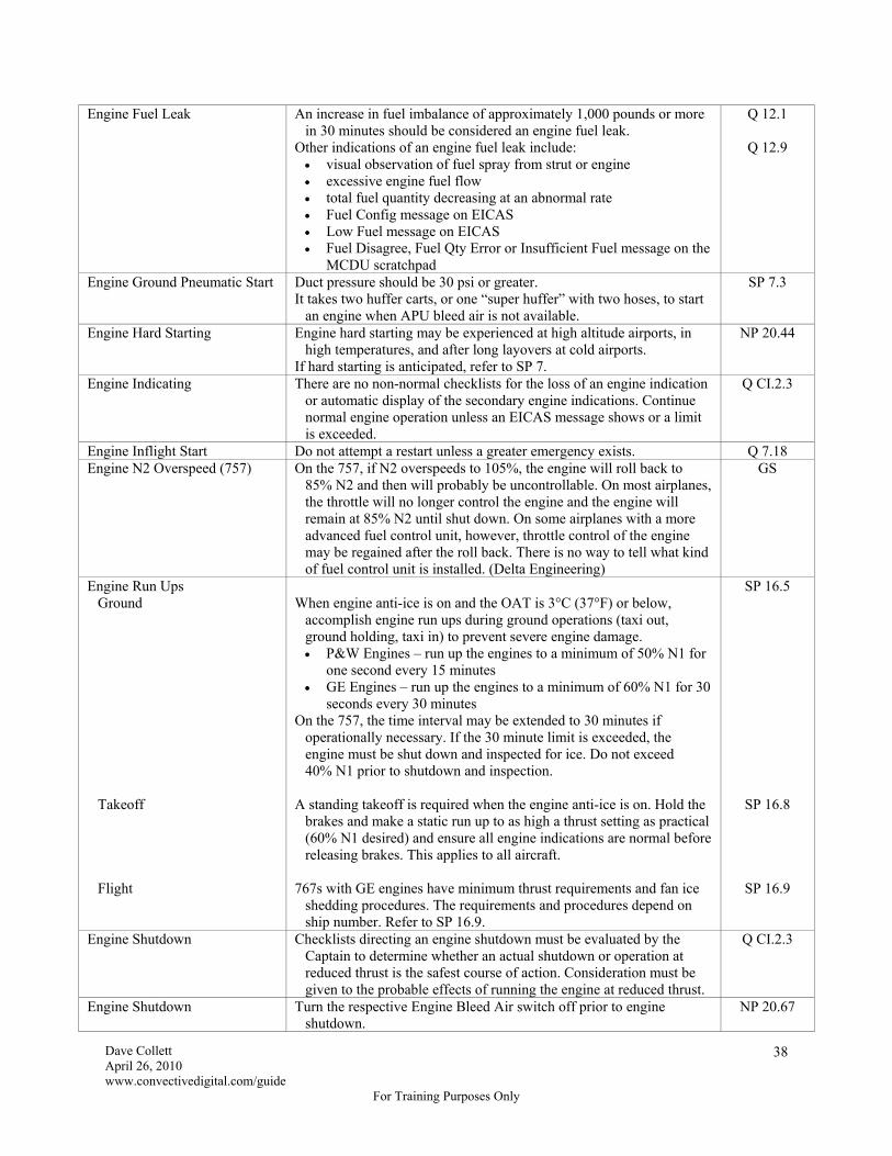
Dave Collett April 26, 2010 www.convectivedigital.com/guide
For Training Purposes Only
38
Engine Fuel Leak An increase in fuel imbalance of approximately 1,000 pounds or more in 30 minutes should be considered an engine fuel leak.
Other indications of an engine fuel leak include: visual observation of fuel spray from strut or engine excessive engine fuel flow total fuel quantity decreasing at an abnormal rate Fuel Config message on EICAS Low Fuel message on EICAS Fuel Disagree, Fuel Qty Error or Insufficient Fuel message on the
MCDU scratchpad
Q 12.1
Q 12.9
Engine Ground Pneumatic Start Duct pressure should be 30 psi or greater. It takes two huffer carts, or one “super huffer” with two hoses, to start
an engine when APU bleed air is not available.
SP 7.3
Engine Hard Starting Engine hard starting may be experienced at high altitude airports, in high temperatures, and after long layovers at cold airports.
If hard starting is anticipated, refer to SP 7.
NP 20.44
Engine Indicating There are no non-normal checklists for the loss of an engine indication or automatic display of the secondary engine indications. Continue normal engine operation unless an EICAS message shows or a limit is exceeded.
Q CI.2.3
Engine Inflight Start Do not attempt a restart unless a greater emergency exists. Q 7.18 Engine N2 Overspeed (757) On the 757, if N2 overspeeds to 105%, the engine will roll back to
85% N2 and then will probably be uncontrollable. On most airplanes, the throttle will no longer control the engine and the engine will remain at 85% N2 until shut down. On some airplanes with a more advanced fuel control unit, however, throttle control of the engine may be regained after the roll back. There is no way to tell what kind of fuel control unit is installed. (Delta Engineering)
GS
Engine Run Ups Ground Takeoff Flight
When engine anti-ice is on and the OAT is 3°C (37°F) or below,
accomplish engine run ups during ground operations (taxi out, ground holding, taxi in) to prevent severe engine damage. P&W Engines – run up the engines to a minimum of 50% N1 for
one second every 15 minutes GE Engines – run up the engines to a minimum of 60% N1 for 30
seconds every 30 minutes On the 757, the time interval may be extended to 30 minutes if
operationally necessary. If the 30 minute limit is exceeded, the engine must be shut down and inspected for ice. Do not exceed 40% N1 prior to shutdown and inspection.
A standing takeoff is required when the engine anti-ice is on. Hold the
brakes and make a static run up to as high a thrust setting as practical (60% N1 desired) and ensure all engine indications are normal before releasing brakes. This applies to all aircraft.
767s with GE engines have minimum thrust requirements and fan ice
shedding procedures. The requirements and procedures depend on ship number. Refer to SP 16.9.
SP 16.5
SP 16.8
SP 16.9
Engine Shutdown Checklists directing an engine shutdown must be evaluated by the Captain to determine whether an actual shutdown or operation at reduced thrust is the safest course of action. Consideration must be given to the probable effects of running the engine at reduced thrust.
Q CI.2.3
Engine Shutdown Turn the respective Engine Bleed Air switch off prior to engine shutdown.
NP 20.67

Dave Collett April 26, 2010 www.convectivedigital.com/guide
For Training Purposes Only
39
Engine Start Start selector to GND Fuel Control to Run Engine Start Abort Conditions Pratt & Whitney Engines Starter Duty Cycle
Verify N2 rotation and oil pressure rise At 25% N2 or max motoring with 757 - 18% N2 minimum (magenta radial) 767 - 15% N2 minimum (magenta radial)
Oil pressure does not rise after selecting GND Fuel flow is abnormally high or fluctuating EGT fails to rise within 20 seconds of selecting RUN EGT rises rapidly or approaches the limit N1 fails to increase after EGT rise EGT quickly nears or exceeds the start limit Oil pressure indication is not normal by the time the engine is
stabilized at idle Do not advance thrust beyond that required for taxi until oil
temperature reaches 50°C. Continuous for 5 minutes Cool 30 seconds per minute of operation After 2 consecutive 5-minute cycles, cool for 10 minutes prior to each
subsequent starter duty cycle.
NP 20.44
NP 20.45
Engine Start It’s possible for the TMC to dump the assumed temperature when power swaps during engine start, so check EICAS to make sure the correct takeoff power is set after both engines are started.
It’s also possible for the autobrakes to return to Off from RTO during power swaps, but autobrakes are on the After Start checklist.
GS
Engine Start (767 only) Attempting to configure the aircraft (lower flaps) during engine start may result in a slow or hot start. (Flap extension causes the Air Demand Pump to operate, which reduces airflow from the APU to the engine starter and may cause a hot start or a hung start.)
NP 20.44
Engine Start Stabilized An engine is stabilized after start when the maximum EGT limit radial (red radial) disappears and after the starting EGT peaks.
NP 20.45
Engine Tailpipe Fire Complete the Engine Tailpipe Fire checklist only if a fire is reported and there is no engine fire warning. If an engine fire warning is present, complete the Engine Fire or Severe Damage or Separation memory items and checklist.
Q 8.8
Engine Thrust Control The Engine Limit or Surge or Stall checklist is written to include situations where the engine does not respond to thrust lever movement. In some situations, however, immediate engine shutdown may be necessary to maintain directional control.
T 8.9
Engine Warm Up and Cool Down Times
Warm Up: 5 minutes desired, 3 minutes minimum Cool Down: 3 minutes or gate arrival
NP 20.50 NP 20.70
Equipment Overheat Avionics on Standby Busses Avionics not on Standby
Busses
Reliable for 90 minutes (includes standby flight instruments) Imminent failure (includes EFIS displays)
Q 2.13
Equipment VALVE Light (767) An equipment cooling valve is not in the commanded position. If the light remains on 30 seconds after selecting STBY, the airplane
may not pressurize. Do not take off.
Q 2.26
Escape slides Escape slides and powered door opening disarm automatically when doors are opened from outside the aircraft.
SP 1.3

Dave Collett April 26, 2010 www.convectivedigital.com/guide
For Training Purposes Only
40
Expected Takeoff Report An Expected Takeoff (ETO) report is required when the time between pushback and takeoff exceeds, or is expected to exceed, the taxi time shown on the flight plan plus 15 minutes. However, ACARS doesn’t know the expected taxi time and will prompt for an ETO report 15 minutes after pushback even if it’s not required yet.
J 6-44
False Glideslope An incorrect final approach fix crossing altitude indicates a possible false glideslope capture (or an incorrect altimeter setting). Do not continue the approach unless in visual conditions.
T 5.16
Fast/Slow Indicator The Fast/Slow indicator on the ADI is anticipatory. Use it as a trend indicator for setting power instead of waiting for the airspeed to respond. It works especially well on single-engine approaches.
GS
Fighter Pilots Beware Boeing seems pretty serious about not using too much rudder. In addition to the warning in Limitations, the following admonitions are published in various places:
Approach to Stall Recovery
Lateral control is maintained with ailerons. Rudder control should not be used because it causes yaw and the resultant roll is undesirable.
Upset Recovery
Careful use of rudder to aid roll control should be considered only if roll control is ineffective and the airplane is not stalled. Warning: Excessive use of pitch trim or rudder may aggravate an upset situation or may result in loss of control and/or high structural loads.
Recovery from a Fully Developed Stall
Finally, if normal pitch control then roll control is ineffective, careful rudder input in the direction of the desired roll may be required to initiate a rolling maneuver recovery. Warning: Only a small amount of rudder is needed. Too much rudder applied too quickly or held too long may result in loss of lateral and directional control.
Upset Recovery
The manufacturer strongly recommends that rudder not be used in stall or unusual attitude recoveries. Ailerons/spoilers should provide the rolling moment in either case. If, however, the application of full lateral control (ailerons) is not sufficient, it may be necessary to judiciously apply some rudder in the direction of the desired roll. Caution: It is important to use the rudder in a manner that avoids large sideslip angles and the resulting excessive roll rates. If the pilot reacts to an abrupt roll onset with a large rudder input followed by a large rudder input in the opposite direction, the resulting yaw amplitude oscillations may be beyond the structural design limits of the aircraft.
Q Man.1.1
Q Man.1.12
T 7.22
T 7.29

Dave Collett April 26, 2010 www.convectivedigital.com/guide
For Training Purposes Only
41
Final Approach Segment Non-Precision Precision
Starts at the FAF or the FAP FAF – Maltese Cross FAP – on course inbound (5-5-1 dot or “5-5-½ alive”)
Starts at the FAF or FAP (ICAO), which is defined as on the localizer
with the glideslope centered at the published glideslope intercept altitude. When ATC directs a lower-than-published glide slope intercept altitude, it is the resultant actual point of glide slope intercept.
J 3-32
Fire Extinguisher If a fire extinguisher is discharged in the cockpit, wear oxygen masks set to 100% oxygen with Emergency selected.
II
Fire Extinguishers Halon Water
All fires, but primarily on electrical, fuel and grease fires. Fabric, paper and wood fires only.
II
Fire Fighting Remove power source from electrical fires as soon as possible. Avoid discharging fire extinguishers directly on people due to possible
suffocating effects. (A weapon against terrorists.) Do not discharge too close to a fire as the discharge may scatter the
fire. Stay away from the fuel source. Avoid breathing vapors, fumes and heated smoke as much as possible.
II
Fire in a Laptop or PED Isolate the burning unit if at all possible. A water fire extinguisher or any non-flammable liquid will be most
effective at cooling the fire and keeping it from spreading. If water is not available or the flames persist, use a Halon fire
extinguisher.
F 7.1.10
Fire Switches Engine APU Forward Cargo Aft Cargo
Silences the fire bell Arms both fire bottles Closes engine and spar fuel valves (6 items) Closes the bleed valve Trips the generator Shuts off fluid to the engine-driven hydraulic pump Silences the fire bell (and nose gear horn if on the ground) Arms the APU fire bottle(s) Shuts down the APU (backs up auto shutdown if on the ground with
both engines shut down) Closes the APU fuel valve (6 items) Trips the APU generator Closes the APU bleed valve Arms all cargo fire extinguisher bottles Arms the compartment extinguisher valve Turns off both recirc fans Arms all cargo fire extinguisher bottles Arms the compartment extinguisher valve Turns off the right recirc fan (757) or both recirc fans (767) Inhibits high flow from both packs (767 only)
II
Fire Testing Engine, APU and Cargo – 19 lights and a bell Wheel well – 5 lights and a bell
SP 8.1 SP 8.2

Dave Collett April 26, 2010 www.convectivedigital.com/guide
For Training Purposes Only
42
First Flight of the Day/ETOPS Checks
The First Flight of the Day/ETOPS checks need only be accomplished prior to the first flight after midnight local time or prior to an ETOPS flight.
NP 20.14
First Officer Minimums Lowest Vis for Takeoff Lowest Vis for Approach
RVR 1600 (500 m) or ¼ sm (400 m) RVR 1800 (550 m) or ½ sm (800 m) and 200' HAT (CAT I ILS)
J 3-21
J 3-33 First Officer Takeoff If the First Officer is making the takeoff, he must keep his hand on the
thrust levers until takeoff power is set. After takeoff thrust is set, he must verbalize the transfer of thrust lever control to the Captain. The Captain’s hand must then remain on the thrust levers until V1.
NP 20.56
Flap Extension Schedule Flap Retraction Schedule
The command bug speed may be set as desired by the PF. Call for flap extension to the next flap setting prior to slowing below
the maneuvering speed for the existing flap position. Do not use flaps as drag devices. Slow using the speedbrakes instead. As the aircraft decelerates: select Flaps 1 at Vref 30 + 80 select Flaps 5 at Vref 30 + 60 select Flaps 15 or 20 at Vref 30 + 40 select Flaps 25 or 30 at Vref 30 + 20
With the aircraft accelerating: select Flaps 5 at Vref 30 + 20 on a Flaps 15 or 20 takeoff select Flaps 1 at Vref 30 + 40
select Flaps Up at Vref 30 + 60
NP 20.62
NP 20.58
Flap Movement at the Gate Do not move the flaps on the ground without appropriate clearance from ground personnel.
NP 20.25
Flap or Slat Malfunction A landing configuration warning will occur on a go-around if the gear is raised with the flap position greater than 20.
T 8.16
Flaps 25 Landing Considerations
Using Flaps 25 for final approach and landing reduces fuel burn significantly as compared to Flaps 30, however Flaps 30 should be used for all 757-300 aircraft and 767 aircraft equipped with steel brakes.
Flights are dispatched to land with Flaps 30, but both Flaps 30 and Flaps 25 landing distances are in the ODM.
Flaps 25 may be used without reference to the ODM provided the conditions in the chart in Normal Procedures are met.
NP 30.14
Flight Attendant Briefing Topics should include: All Flights security considerations flight deck entry/exit procedures planned flight time and altitude enroute/destination weather including turbulence requirement for passenger overwater briefing coordination of PAs, including warm weather PA extra crew members for international operations, confirm with the Flight Leader that
all flight attendants have the required documentation (passports, visas, vaccinations, etc.)
First Flight of the Day or After a Crew Change Seat Belt/No Smoking sign use review cabin discrepancies passenger misconduct procedures
F 3.3.1

Dave Collett April 26, 2010 www.convectivedigital.com/guide
For Training Purposes Only
43
Flight Attendant Initiated Evacuation
In an emergency situation, if the flight crew has not provided necessary direction, the Flight Leader will attempt to contact the cockpit. In a life threatening situation (fire, smoke or structural damage) and once the aircraft has come to a complete and final stop, flight attendants have the authority to initiate evacuation without instructions from the cockpit.
F 10.1.5
Flight Attendant Staffing 757-200 757-300 and 767ER 767 Boarding and Deplaning Through Flights
4 for dispatch, 2 for through flights 5 for dispatch, 2 for through flights 6 for dispatch, 3 for through flights The minimum number of flight attendants for dispatch must be on
board during boarding and deplaning. The minimum number of flight attendants for through flights must be
on board during enroute stopovers when passengers are on board and not boarding or deplaning.
F 3.2.10
Flight Control Computers Autopilot engagement requires at least two Flight Control Computers (FCCs). The left and center FCCs are powered by the left AC bus, so all autopilots will be inop with a failed left AC bus. The right FCC is on the right AC bus, so the left and center autopilots will be available with a failed right AC bus. The right autopilot will be inoperative, however.
II
Flight Deck Door Lock Fail Light Auto Unlk Light Deny Switch
Indicates failure of the door locking mechanism. Door is not
electronically locked. Indicates access code has been entered and door will unlock in 30-60
seconds unless Deny is selected. Cancels keypad entry request and starts a 5 minute keypad lockout
period to deny cockpit access. Hold for one second.
II
Flight Director On the ground, when the flight director is turned on it should command wings level, 8° ANU and the flight mode annunciations should be TO, TO, FD.
NP 20.35
Flight Director Guidance on Departure
When hand-flying a departure, the flight director will not provide lead turn guidance in LNAV mode. If engaged, however, the autopilot will lead the flight director and fly the programmed ground track. Therefore, the autopilot is recommended for RNAV departures, strict noise abatement departures and other departure procedures where ground track is critical.
GS
Flight Director Guidance on Takeoff and Go-Around
On takeoff the flight director commands V2 + 15 knots or liftoff speed + 15 knots, whichever is higher. If the current airspeed remains above the target speed for 5 seconds, the target speed resets to the current airspeed up to a maximum of V2 + 25 knots. If the MCP airspeed is manually increased, the flight director will command the increased airspeed.
On go-around the autothrottles provide a climb of at least 2,000 fpm and the flight director commands a climb at current airspeed or MCP airspeed, whichever is higher. If the airspeed increases above the initial target speed and remains there for 5 seconds, the target speed resets to the current airspeed up to a maximum of MCP speed plus 25 knots. If the initial go-around speed was above MCP speed plus 25 knots, that speed is maintained.
On takeoff the flight director commands the ground track at time of lift off.
On go-around the flight director commands the ground track at time of engagement.
II

Dave Collett April 26, 2010 www.convectivedigital.com/guide
For Training Purposes Only
44
Flight Dispatch Release Amendments
An amendment to the FDR is required for: ship change Dispatcher-approved MEL additions and deletions CDL additions and deletions route changes in excess of FOM guidance takeoff or destination alternate additions or deletions return to the gate or return to the departure airport for any reason weight changes that exceed the maximum takeoff weight fuel overfills or additions of more than 1,000 pounds for narrow
body or 1,500 pounds for wide body any other appropriate circumstances
F 5.2.4
Flight Level Change Flight Level Change has logic to allow shallow climbs and descents for small altitude changes. There is no need to use Vertical Speed for passenger comfort.
T 1.35
Flight Level Change Flight Level Change uses a two minute rule (125 seconds) to prevent the autothrottles from using full climb or idle power for small altitude changes.
GS
Flight Watch Communications between the airplane and the company must be possible at all times to comply with FAR flight watch requirements.
Whenever the engines are running, the First Officer shall maintain flight watch requirements by: ensuring ACARS is operating properly (NO COMM not
displayed) or using SATCOM or selecting the proper VHF/HF frequency with a successful
SELCAL check or selecting the proper VHF/HF frequency and maintaining a
listening watch If both HF radios are being used for ATC, you are complying with
flight watch requirements. Delta knows where you are and can contact you through ATC.
J 6-41
Flights Without Flight Attendants
Secure the cabin (carts, galleys, overhead bins, closets, lavs, etc.) and arm at least the 1L and 1R doors.
Disarm the doors after block-in and signal the agent when it is safe to open the main entry door.
SP 1.1
FMS Anomaly Going direct to a fix with Abeam Points selected will cause temperatures entered on the Wind page to zero out, possibly leading to an Insufficient Fuel warning. Temperatures need to be reentered for accurate fuel calculations.
FCB 08-13
FMS Anomaly In rare cases, the FMS will not go directly to the fix you entered. If there is a fix with a step climb between the aircraft’s present position and the desired direct fix, sometimes some FMSs will go to the step climb fix first and then to the desired direct fix, which could lead to a violation. Always check the FMS routing after executing. (Yes, it really happens sometimes.)
GS
FMS Database Do not assume the first NAVAID or fix listed in the FMS is the correct one.
J 7-4
FMS Time Calculations The FMS will calculate two different estimates for the active waypoint. The time shown on the HSI is based only on current winds. The time shown on the CDU is based on a mixture of current winds and forecast winds loaded into the FMS. The mixture depends on the distance to the active waypoint. If the waypoint is a long way away, most of the time calculation will be based on forecast winds. If the waypoint is close, most of the calculation will be based on current winds.
GS

Dave Collett April 26, 2010 www.convectivedigital.com/guide
For Training Purposes Only
45
FMS Wind Extrapolation If an aircraft climbs above the highest loaded forecast wind, the FMS uses the highest loaded forecast wind without extrapolation. For example, if winds at FL350 are loaded and the aircraft climbs to FL370, the FMS uses the winds at FL350 without extrapolation.
If an aircraft descends below the lowest loaded forecast wind, the FMS keeps the direction constant but extrapolates the speed uniformly to zero at the surface. For example, if winds at FL270 are loaded and the aircraft descends to FL250, the FMS will use winds from the same direction but extrapolated to a lower speed.
GS
FMS Wind Propagation The wind entry at a waypoint is propagated forward to all downtrack waypoints until the next entry or the top of descent. In addition, the wind entry at a waypoint is propagated backward to the airplane’s present position if no other entries have been made. This can cause problems with FMC time calculations if not corrected. For example, assume a flight intends to cross the Atlantic at FL330 and then step to FL350 over Europe. The crew loads strong forecast winds into the FMS at FL330 for the crossing and light winds at FL350 for the journey across Europe. In this case, the light winds at FL350 will propagate all the way back across the Atlantic. If the flight is cleared to actually cross the ocean at FL350 instead of FL330, the FMS will be using light winds for its calculations and the time estimates will be wrong. The solution, of course, is to load the correct winds for the actual flight level flown.
GS
Food Consumption Pilots should not eat identical meals from the same kitchen within 6 hours of flight.
Pilots may eat the same meal in flight provided the meals are staggered so that one pilot is monitoring the aircraft at all times.
Crew members should not eat any food provided by a passenger.
F 3.2.14
Frost Takeoff with a light coating of frost up to 1/8 inch (3 mm) thick on the lower wing surfaces due to cold fuel is permissible, however all leading edge devices, all control surfaces, upper wing surfaces, and winglet surfaces must be free of snow and ice.
Thin hoar frost is acceptable on the upper surface of the fuselage provided all vents and ports are clear. Thin hoarfrost is a uniform white deposit of fine crystalline texture, which usually occurs on exposed surfaces on a cold and cloudless night, and which is thin enough to distinguish surface features underneath, such as paint lines, markings or lettering.
If the hoar frost extends down to the window area, the fuselage must be de-iced.
SP 16.2
SP 16.17
Fuel Burn to an Alternate Fuel burn to an alternate airport is calculated at planned landing weight from a static takeoff at the destination airport and then flying normal climb, cruise and descent profiles to the alternate via the shortest available route while observing overwater and area navigation restrictions.
F 5.3.9
Fuel Cap Requirements Flight crews are responsible for checking the fuel cap requirement on the Fuel Service Record. Only the 767ER requires fuel caps.
When Electronic Fuel Service Record procedures are used, fuel tolerance and fuel cap compliance are verified electronically.
F 5.4.10
Fuel Config Light 1,800 pound fuel imbalance (757). 2,000 ± 500 pound fuel imbalance (767). 1,200 lbs or more in the center tank with center fuel pumps off. 2,200 lbs or less in a main tank (LOW FUEL message too).
II
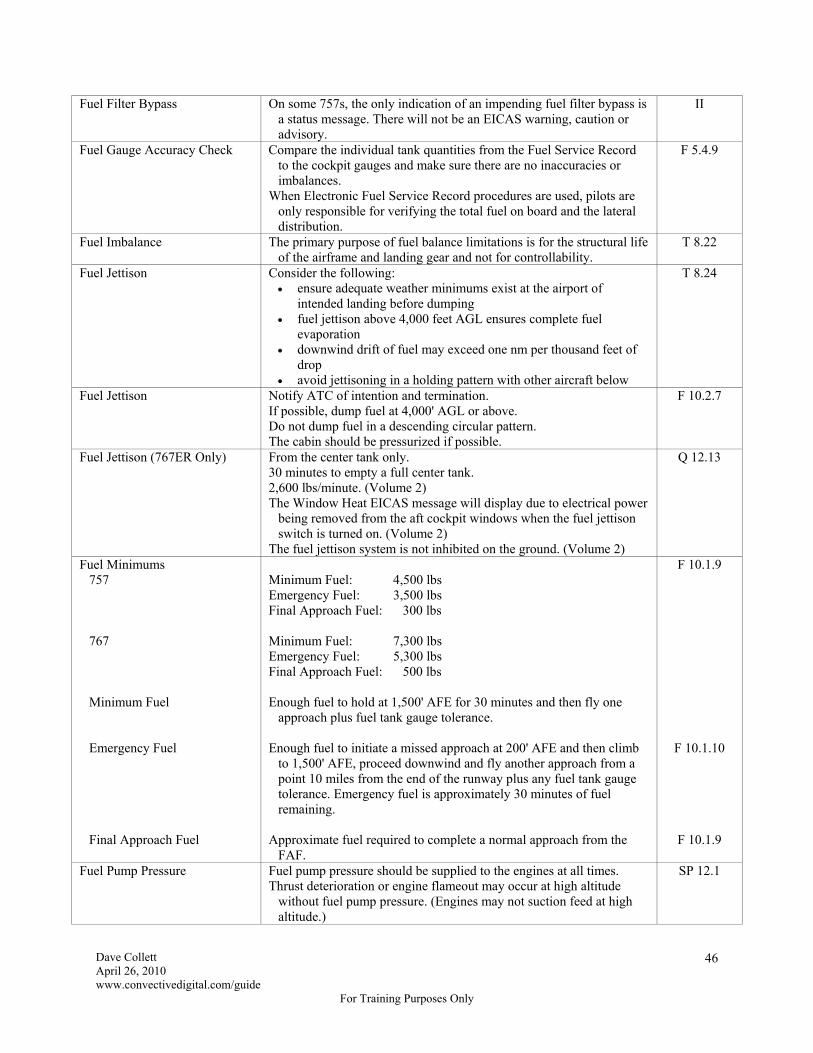
Dave Collett April 26, 2010 www.convectivedigital.com/guide
For Training Purposes Only
46
Fuel Filter Bypass On some 757s, the only indication of an impending fuel filter bypass is a status message. There will not be an EICAS warning, caution or advisory.
II
Fuel Gauge Accuracy Check Compare the individual tank quantities from the Fuel Service Record to the cockpit gauges and make sure there are no inaccuracies or imbalances.
When Electronic Fuel Service Record procedures are used, pilots are only responsible for verifying the total fuel on board and the lateral distribution.
F 5.4.9
Fuel Imbalance The primary purpose of fuel balance limitations is for the structural life of the airframe and landing gear and not for controllability.
T 8.22
Fuel Jettison Consider the following: ensure adequate weather minimums exist at the airport of
intended landing before dumping fuel jettison above 4,000 feet AGL ensures complete fuel
evaporation downwind drift of fuel may exceed one nm per thousand feet of
drop avoid jettisoning in a holding pattern with other aircraft below
T 8.24
Fuel Jettison Notify ATC of intention and termination. If possible, dump fuel at 4,000' AGL or above. Do not dump fuel in a descending circular pattern. The cabin should be pressurized if possible.
F 10.2.7
Fuel Jettison (767ER Only) From the center tank only. 30 minutes to empty a full center tank. 2,600 lbs/minute. (Volume 2) The Window Heat EICAS message will display due to electrical power
being removed from the aft cockpit windows when the fuel jettison switch is turned on. (Volume 2)
The fuel jettison system is not inhibited on the ground. (Volume 2)
Q 12.13
Fuel Minimums 757 767 Minimum Fuel Emergency Fuel Final Approach Fuel
Minimum Fuel: 4,500 lbs Emergency Fuel: 3,500 lbs Final Approach Fuel: 300 lbs Minimum Fuel: 7,300 lbs Emergency Fuel: 5,300 lbs Final Approach Fuel: 500 lbs Enough fuel to hold at 1,500' AFE for 30 minutes and then fly one
approach plus fuel tank gauge tolerance. Enough fuel to initiate a missed approach at 200' AFE and then climb
to 1,500' AFE, proceed downwind and fly another approach from a point 10 miles from the end of the runway plus any fuel tank gauge tolerance. Emergency fuel is approximately 30 minutes of fuel remaining.
Approximate fuel required to complete a normal approach from the
FAF.
F 10.1.9
F 10.1.10
F 10.1.9
Fuel Pump Pressure Fuel pump pressure should be supplied to the engines at all times. Thrust deterioration or engine flameout may occur at high altitude
without fuel pump pressure. (Engines may not suction feed at high altitude.)
SP 12.1
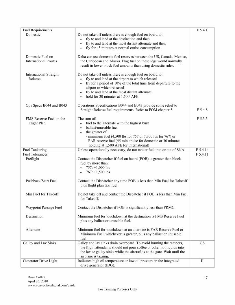
Dave Collett April 26, 2010 www.convectivedigital.com/guide
For Training Purposes Only
47
Fuel Requirements Domestic Domestic Fuel on
International Routes International Straight
Release Ops Specs B044 and B043 FMS Reserve Fuel on the
Flight Plan
Do not take off unless there is enough fuel on board to: fly to and land at the destination and then fly to and land at the most distant alternate and then fly for 45 minutes at normal cruise consumption
Delta can use domestic fuel reserves between the US, Canada, Mexico,
the Caribbean and Alaska. Flag fuel on these legs would normally result in lower block fuel amounts than using domestic rules.
Do not take off unless there is enough fuel on board to: fly to and land at the airport to which released fly for a period of 10% of the total time from departure to the
airport to which released fly to and land at the most distant alternate hold for 30 minutes at 1,500' AFE
Operations Specifications B044 and B043 provide some relief to
Straight Release fuel requirements. Refer to FOM chapter 5. The sum of: fuel to the alternate with the highest burn ballast/unusable fuel the greater of:
- minimum fuel (4,500 lbs for 757 or 7,300 lbs for 767) or - FAR reserve fuel (45 min cruise for domestic or 30 minutes
holding at 1,500 AFE for international)
F 5.4.1
F 5.4.8
F 5.3.5
Fuel Tankering Unless operationally necessary, do not tanker fuel into or out of SNA. F 5.4.14 Fuel Tolerances Preflight Pushback/Start Fuel Min Fuel for Takeoff Waypoint Passage Fuel Destination Alternate
Contact the Dispatcher if fuel on board (FOB) is greater than block
fuel by more than: 757: +1,000 lbs 767: +1,500 lbs
Contact the Dispatcher any time FOB is less than Min Fuel for Takeoff
plus flight plan taxi fuel. Do not take off and contact the Dispatcher if FOB is less than Min Fuel
for Takeoff. Contact the Dispatcher if FOB is significantly less than PRMG. Minimum fuel for touchdown at the destination is FMS Reserve Fuel
plus any ballast or unusable fuel. Minimum fuel for touchdown at an alternate is FAR Reserve Fuel or
Minimum Fuel, whichever is greater, plus any ballast or unusable fuel.
F 5.4.11
Galley and Lav Sinks Galley and lav sinks drain overboard. To avoid burning the rampers, the flight attendants should not pour coffee or other hot liquids into the lav or galley sinks while the aircraft is at the gate. Wait until the airplane is taxiing.
GS
Generator Drive Light Indicates high oil temperature or low oil pressure in the integrated drive generator (IDG).
II

Dave Collett April 26, 2010 www.convectivedigital.com/guide
For Training Purposes Only
48
Go-Around and Missed Approach
The terms “Go-Around” and “Missed Approach” are synonymous. NP 10.12
Go-Around Armed Go-Around is armed when the flaps are extended on any approach or at glideslope capture on an ILS if glideslope capture occurs first.
II
Go-Around Call Any pilot may call a Go-Around and the call must be honored. F 3.4.9 Grooved Runways and Porous
Friction Overlays When wet, grooved runways and runways with a porous friction
overlay provide braking action approximately equal to a dry runway. 757-300 aircraft, however, may not consider a wet runway to be dry
even if the runway is grooved or has a porous friction overlay.
F 5.6.15
Headsets and Boom Microphones
Headsets and boom microphones are required below 18,000 feet including accomplishing checklists on the ground through completion of the Shutdown checklist.
F 3.4.6
HF Emergency Frequency 2182 kHz. Monitored by Coast Guard Rescue Coordination Centers, Coast Guard
units, most commercial coast stations and some ships. Range is generally less than 300 miles. Merchant ships may be contacted on 4125 kHz or 2182 kHz. Some ships can provide a homing signal on 410 kHz.
J 9 US-13
Q CI.2.11
HF Radio Check An HF radio preflight check is not required if it can be determined the HF radio was used on the last flight and was not written up in the logbook.
A SELCAL check is not a required component of the HF radio check. If the coupler tone, side tone and audio reception are heard, the HF
radio is considered to be working and the flight may proceed. You must obtain two-way HF radio communications before entering
areas requiring HF communications. A successful SELCAL check is desired to preclude maintaining a listening watch.
J 6-6
HF Radios Do not operate the HF radio while fueling is in progress. USB is preferable for HF communications. AM should be off. Decreasing sensitivity too far prevents reception, including SELCAL
monitoring of the HF radio.
SP 5.40
Holding Maintain clean configuration if holding in icing conditions or turbulence.
T 4.30
Holding Fix The holding fix must be a route waypoint (on the Legs page) or the present position to use the FMS for holding.
SP 11.19
Holding Speed Not Available If holding speed is not available from the FMC, refer to the ODM for the correct speed. If time does not permit immediate reference to the ODM, the following schedule may be used temporarily: flaps up maneuvering speed at low altitudes Vref 30 + 100 knots above FL 250
T 4.31
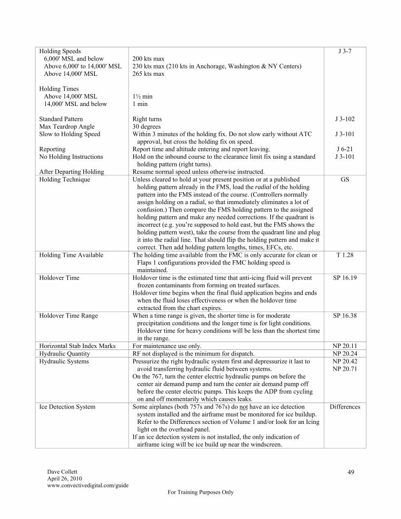
Dave Collett April 26, 2010 www.convectivedigital.com/guide
For Training Purposes Only
49
Holding Speeds 6,000' MSL and below Above 6,000' to 14,000' MSL Above 14,000' MSL Holding Times Above 14,000' MSL 14,000' MSL and below Standard Pattern Max Teardrop Angle Slow to Holding Speed Reporting No Holding Instructions After Departing Holding
200 kts max 230 kts max (210 kts in Anchorage, Washington & NY Centers) 265 kts max 1½ min 1 min Right turns 30 degrees Within 3 minutes of the holding fix. Do not slow early without ATC
approval, but cross the holding fix on speed. Report time and altitude entering and report leaving. Hold on the inbound course to the clearance limit fix using a standard
holding pattern (right turns). Resume normal speed unless otherwise instructed.
J 3-7
J 3-102
J 3-101
J 6-21 J 3-101
Holding Technique Unless cleared to hold at your present position or at a published holding pattern already in the FMS, load the radial of the holding pattern into the FMS instead of the course. (Controllers normally assign holding on a radial, so that immediately eliminates a lot of confusion.) Then compare the FMS holding pattern to the assigned holding pattern and make any needed corrections. If the quadrant is incorrect (e.g. you’re supposed to hold east, but the FMS shows the holding pattern west), take the course from the quadrant line and plug it into the radial line. That should flip the holding pattern and make it correct. Then add holding pattern lengths, times, EFCs, etc.
GS
Holding Time Available The holding time available from the FMC is only accurate for clean or Flaps 1 configurations provided the FMC holding speed is maintained.
T 1.28
Holdover Time Holdover time is the estimated time that anti-icing fluid will prevent frozen contaminants from forming on treated surfaces.
Holdover time begins when the final fluid application begins and ends when the fluid loses effectiveness or when the holdover time extracted from the chart expires.
SP 16.19
Holdover Time Range When a time range is given, the shorter time is for moderate precipitation conditions and the longer time is for light conditions. Holdover time for heavy conditions will be less than the shortest time in the range.
SP 16.38
Horizontal Stab Index Marks For maintenance use only. NP 20.11 Hydraulic Quantity RF not displayed is the minimum for dispatch. NP 20.24 Hydraulic Systems Pressurize the right hydraulic system first and depressurize it last to
avoid transferring hydraulic fluid between systems. On the 767, turn the center electric hydraulic pumps on before the
center air demand pump and turn the center air demand pump off before the center electric pumps. This keeps the ADP from cycling on and off momentarily which causes leaks.
NP 20.42 NP 20.71
Ice Detection System Some airplanes (both 757s and 767s) do not have an ice detection system installed and the airframe must be monitored for ice buildup. Refer to the Differences section of Volume 1 and/or look for an Icing light on the overhead panel.
If an ice detection system is not installed, the only indication of airframe icing will be ice build up near the windscreen.
Differences

Dave Collett April 26, 2010 www.convectivedigital.com/guide
For Training Purposes Only
50
Icing The greatest threat of inflight icing is between 0°C and -15°C OAT. The threat decreases as the OAT decreases to -40°C.
Operations into known severe icing conditions are prohibited. Make a report to both ATC and Flight Control when encountering
moderate or severe icing.
J 4-49
J 4-51 J 4-52
ILS Critical Signal Areas Protected when the ceiling is less than 800' or the visibility is 2 sm or less. Autoland approaches can be flown without contacting ATC.
In foreign countries, however, notify ATC if an autoland will be conducted and the ceiling is 200' or greater and visibility is greater than RVR 2000 (600 meters).
J 3-15
Increased Rotation Speed for Windshear
If unstable weather conditions exist, it may be advisable to increase rotation speed. Set V1, VR and V2 based on actual takeoff weight and obtain an increased rotation speed from the ODM based on RATOW from the AWABS. The increased rotation speed may not be more than 20 knots above the actual VR. Mentally note the increased rotation speed and rotate at that speed using a normal rotation rate.
If actual windshear is encountered above the normal VR, do not attempt to accelerate to the increased VR, but rotate without hesitation.
SP 16.59
In-Range Report On the In Range Report, fill in the total number of wheelchairs required at the destination and any unaccompanied minors that are not already on the Flight Attendant’s Departure Report.
SP 5.27
Intercepting a Radial Outbound Use HDG Select to comply with the ATC clearance. Deselect LNAV if armed. Manually tune the VOR frequency and radial. Select the DIR/INTC page. enter the VOR in the DIRECT TO box at 6L execute create a place-radial/distance waypoint from the VOR (e.g.
ATL180/99) insert the created waypoint at L2, which is below the VOR on L1 execute
Select the DIR/INTC page. line select the created waypoint at L2 to the scratch pad and insert
in the INTC LEG TO box at 6R. Do not enter a course. check the HSI for accuracy. The dashed green and white lines
should overlay. execute
Arm LNAV. Some FMSs do not have a DIR/INTC key or DIR/INTC page. Use the
LEGS page instead.
GS
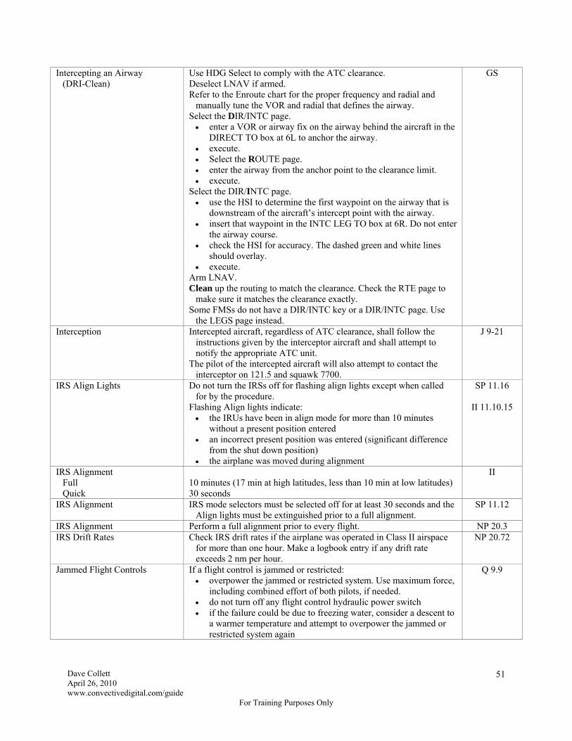
Dave Collett April 26, 2010 www.convectivedigital.com/guide
For Training Purposes Only
51
Intercepting an Airway (DRI-Clean)
Use HDG Select to comply with the ATC clearance. Deselect LNAV if armed. Refer to the Enroute chart for the proper frequency and radial and
manually tune the VOR and radial that defines the airway. Select the DIR/INTC page. enter a VOR or airway fix on the airway behind the aircraft in the
DIRECT TO box at 6L to anchor the airway. execute. Select the ROUTE page. enter the airway from the anchor point to the clearance limit. execute.
Select the DIR/INTC page. use the HSI to determine the first waypoint on the airway that is
downstream of the aircraft’s intercept point with the airway. insert that waypoint in the INTC LEG TO box at 6R. Do not enter
the airway course. check the HSI for accuracy. The dashed green and white lines
should overlay. execute.
Arm LNAV. Clean up the routing to match the clearance. Check the RTE page to
make sure it matches the clearance exactly. Some FMSs do not have a DIR/INTC key or a DIR/INTC page. Use
the LEGS page instead.
GS
Interception Intercepted aircraft, regardless of ATC clearance, shall follow the instructions given by the interceptor aircraft and shall attempt to notify the appropriate ATC unit.
The pilot of the intercepted aircraft will also attempt to contact the interceptor on 121.5 and squawk 7700.
J 9-21
IRS Align Lights Do not turn the IRSs off for flashing align lights except when called for by the procedure.
Flashing Align lights indicate: the IRUs have been in align mode for more than 10 minutes
without a present position entered an incorrect present position was entered (significant difference
from the shut down position) the airplane was moved during alignment
SP 11.16
II 11.10.15
IRS Alignment Full Quick
10 minutes (17 min at high latitudes, less than 10 min at low latitudes) 30 seconds
II
IRS Alignment IRS mode selectors must be selected off for at least 30 seconds and the Align lights must be extinguished prior to a full alignment.
SP 11.12
IRS Alignment Perform a full alignment prior to every flight. NP 20.3 IRS Drift Rates Check IRS drift rates if the airplane was operated in Class II airspace
for more than one hour. Make a logbook entry if any drift rate exceeds 2 nm per hour.
NP 20.72
Jammed Flight Controls If a flight control is jammed or restricted: overpower the jammed or restricted system. Use maximum force,
including combined effort of both pilots, if needed. do not turn off any flight control hydraulic power switch if the failure could be due to freezing water, consider a descent to
a warmer temperature and attempt to overpower the jammed or restricted system again
Q 9.9
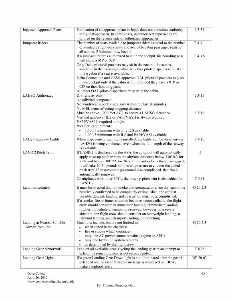
Dave Collett April 26, 2010 www.convectivedigital.com/guide
For Training Purposes Only
52
Jeppesen Approach Plates Publication of an approach plate in Jepps does not constitute authority to fly that approach. In some cases, unauthorized approaches are printed on the reverse side of authorized approaches.
J 3-31
Jumpseat Riders The number of seats available to jumpseat riders is equal to the number of available flight deck seats and available cabin passenger seats in all cabins. (Unlimited flow back.)
If a jumpseat rider is authorized to sit in the cockpit, his boarding pass will show a 01P or 02P.
Only Delta pilots/dispatchers may sit in the cockpit if a seat is available in the passenger cabin. All other pilots/dispatchers must sit in the cabin if a seat is available.
Delta Connection and CASS-approved OAL pilots/dispatchers may sit in the cockpit only if the cabin is full provided they have a 01P or 02P on their boarding pass.
All other OAL pilots/dispatchers must sit in the cabin.
F 4.3.1
F 4.3.5
LAHSO Authorized Dry runway only. No tailwind component. No windshear report or advisory within the last 20 minutes. No MEL items affecting stopping distance. Must be above 1,000 feet AGL to accept a LAHSO clearance. Vertical guidance (ILS or PAPI/VASI) is always required. PAPI/VASI is required at night. Weather Requirements: 1,500/5 minimum with only ILS available 1,000/3 minimum with ILS and PAPI/VASI available
J 3-15
J 3-16
LAHSO Runway Lights When in-pavement lighting is installed, the lights will be on whenever LAHSO is being conducted, even when the full length of the runway is available.
J 3-16
LAND 2 Pitch Trim If LAND 2 is displayed on the ASA, the autopilot will automatically apply nose-up pitch trim as the airplane descends below 330' RA for 757s and below 100' RA for 767s. If the autopilot is then disengaged, it will take 20-30 pounds of forward pressure to counter the added pitch trim. If an automatic go-around is accomplished, the trim is automatically removed.
On airplanes with older FCCs, the nose up pitch trim is also added for LAND 3.
II
T 5.31
Land Immediately It must be stressed that for smoke that continues or a fire that cannot be positively confirmed to be completely extinguished, the earliest possible descent, landing and evacuation must be accomplished.
If a smoke, fire or fumes situation becomes uncontrollable, the flight crew should consider an immediate landing. “Immediate landing” implies immediate diversion to a runway, however, in a severe situation, the flight crew should consider an overweight landing, a tailwind landing, an off-airport landing, or a ditching.
Q CI.2.3
Landing at Nearest Suitable Airport Required
Situations include, but are not limited to: when stated in the checklist fire or smoke which continues only one AC power source remains (engine or APU) only one hydraulic system remains as determined by the flight crew
Q CI.2.3
Landing Gear Abnormals Land on all available gear. Cycling the landing gear in an attempt to extend the remaining gear is not recommended.
T 8.28
Landing Gear Lights If a green Landing Gear Down light is not illuminated after the gear is extended and no Gear Disagree message is displayed on EICAS, make a logbook entry.
NP 20.63
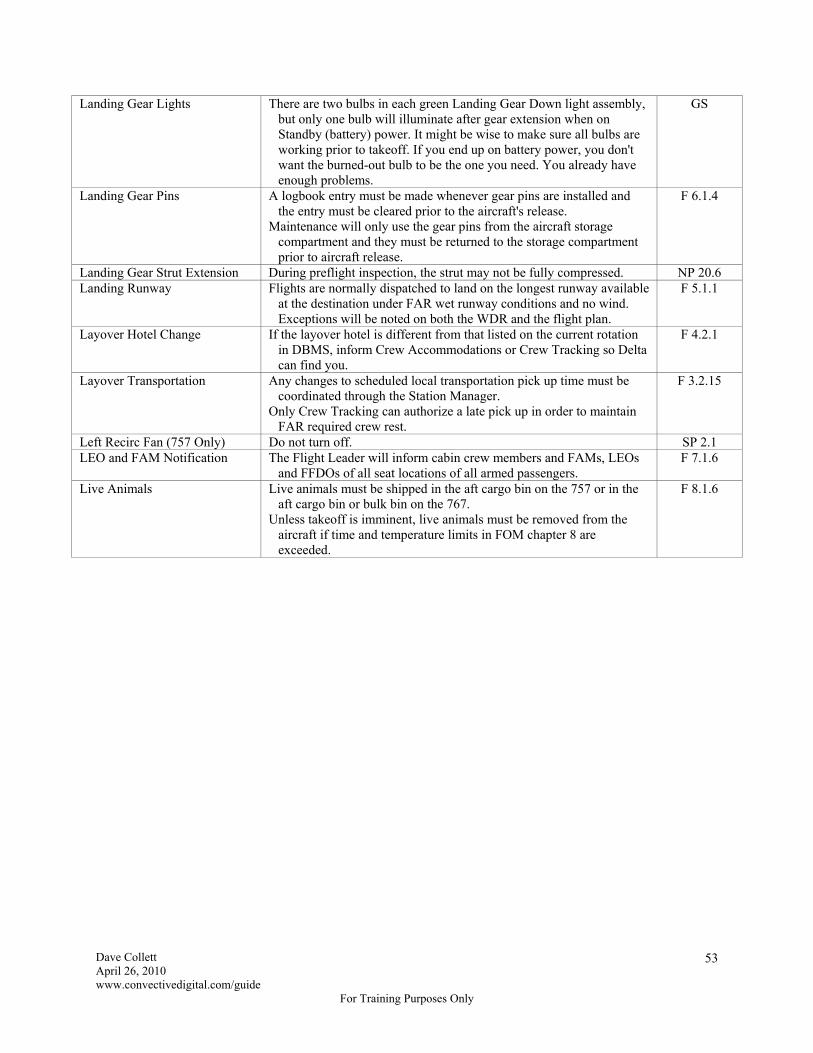
Dave Collett April 26, 2010 www.convectivedigital.com/guide
For Training Purposes Only
53
Landing Gear Lights There are two bulbs in each green Landing Gear Down light assembly, but only one bulb will illuminate after gear extension when on Standby (battery) power. It might be wise to make sure all bulbs are working prior to takeoff. If you end up on battery power, you don't want the burned-out bulb to be the one you need. You already have enough problems.
GS
Landing Gear Pins A logbook entry must be made whenever gear pins are installed and the entry must be cleared prior to the aircraft's release.
Maintenance will only use the gear pins from the aircraft storage compartment and they must be returned to the storage compartment prior to aircraft release.
F 6.1.4
Landing Gear Strut Extension During preflight inspection, the strut may not be fully compressed. NP 20.6 Landing Runway Flights are normally dispatched to land on the longest runway available
at the destination under FAR wet runway conditions and no wind. Exceptions will be noted on both the WDR and the flight plan.
F 5.1.1
Layover Hotel Change If the layover hotel is different from that listed on the current rotation in DBMS, inform Crew Accommodations or Crew Tracking so Delta can find you.
F 4.2.1
Layover Transportation Any changes to scheduled local transportation pick up time must be coordinated through the Station Manager.
Only Crew Tracking can authorize a late pick up in order to maintain FAR required crew rest.
F 3.2.15
Left Recirc Fan (757 Only) Do not turn off. SP 2.1 LEO and FAM Notification The Flight Leader will inform cabin crew members and FAMs, LEOs
and FFDOs of all seat locations of all armed passengers. F 7.1.6
Live Animals Live animals must be shipped in the aft cargo bin on the 757 or in the aft cargo bin or bulk bin on the 767.
Unless takeoff is imminent, live animals must be removed from the aircraft if time and temperature limits in FOM chapter 8 are exceeded.
F 8.1.6

Dave Collett April 26, 2010 www.convectivedigital.com/guide
For Training Purposes Only
54
LNAV Departure Accomplish the following if LNAV will be used for departure (may or may not be an RNAV departure):
Verify the selected runway, departure and associated first fix in the
FMS match the latest ATC departure clearance. Pegasus Airplanes (GPS) if GPS NAV is on, the N1/EPR update function is inhibited if GPS NAV is off, the N1/EPR update function works. Follow
the procedures for PIP airplanes below. PIP Airplanes (no GPS) the FMC updates the airplane’s position to the runway landing
threshold when the N1/EPR switch is pressed. The PM should check runway position on the HSI after the switch is pressed.
if departing from a location other than the runway landing threshold, a position shift value must be entered on the POS SHIFT line on the Takeoff Ref page. This value will be negative if taking off prior to the landing threshold and positive if taking off after the landing threshold. (For example, enter -32 for a takeoff using the full length of Rwy 31L at JFK because the takeoff point is 3,200 feet prior to the landing threshold. Similarly, enter 18 for a taxiway Lima takeoff on Rwy 31L because Lima is 1800 feet beyond the landing threshold.)
do not enter a named intersection or any letters on the POS SHIFT line because they will inhibit the runway update function
All Non-Pegasus Airplanes (no GPS) when approaching the departure runway, check aircraft position
versus runway position on the HSI 10 nm scale if the autothrottles or N1/EPR switch are inop, the FMS will not
update the aircraft’s position to the landing runway threshold. In this case, verify the aircraft symbol is in close proximity to the departure end of the runway symbol with the HSI in the 10 nm scale. Do not use LNAV for departure if the FMS position is incorrect.
the FMS will begin searching for suitable radio updates after the aircraft reaches 100 knots on takeoff roll
NP 30.2
NP 30.3
Logbook Entries If the aircraft has departed the gate and MEL/CDL procedures have been applied, logbook entries and placarding may be delayed until after airborne, however they must be completed before flight termination.
F 3.4.8
Long-Range Navigation System A long-range navigation system (LRNS) is defined as: one FMS and one CDU supported by one or more IRUs or
GPS, or one CDU with alternate nav capability supported by its IRU
(following dual FMC failure with Alternate Nav selected) Not all aircraft have CDUs with alternate nav capability.
GS

Dave Collett April 26, 2010 www.convectivedigital.com/guide
For Training Purposes Only
55
Lost Comm (USA) Squawk 7600 (not 7700 first for simple lost comm). Maintain VFR and land as soon as practical. Note that VFR is not
authorized in Class A airspace. If unable to maintain VFR: route: assigned, vectored, expected or filed. (AVEF) altitude: highest of assigned, minimum or expected
Procedures in Europe and ICAO airspace are different. Refer to Jepps Chapter 9.
J 9-3
J 9-4
Low Fuel Avoid high nose up attitudes and excessive acceleration and deceleration.
Q 12.19
Low Pressure Compressor On the 757, when engine anti-ice will be required and OAT is 3°C or below, perform a visual check for ice build up on the first stage of the low pressure compressor stator. Refer to SP 16.3 for a graphic.
SP 16.3
Low Visibility Runway Requirements
To operate below RVR 4000 (1200 m) or ¾ mile (1200 m) visibility, runway length must be 15% over the FAR dry runway length.
Typically, Delta flights are dispatched to the longest runway assuming wet/low minima conditions. There will be a remark on the flight plan if not the case.
J 3-35
Maintenance Irregularities In Flight
Time permitting, the Captain should contact the MCC for irregularities that occur in flight, especially if the irregularity may lead to a diversion or air turnback.
F 3.4.9
Manual Engine Performance Report
If necessary, complete once every three hours in cruise. Turn the autothrottles off and allow the engines to stabilize 3-5
minutes before taking the snapshot.
SP 7.6
Maximum Altitude When at or near the FMC maximum altitude, it is possible for LNAV inputs (e.g. bank angles) to exceed the capability of the airplane, leading to loss of altitude or airspeed.
Turbulence at or near the maximum altitude can momentarily increase the airplane’s angle of attack and activate the stick shaker.
T 4.9
MCDU Failure Do not enter Class II or MNPS airspace with only one MCDU on any aircraft. Note that a failed MCDU is not the same as a failed FMC.
GS
MCDU Loading If the airplane has a Hybrid MCDU with Alternate Navigation capability, a good technique is to load your best guess for the arrival and approach at the destination in case you lose both FMCs enroute. That way, the approach and arrival will already be stored in the MCDU.
GS
MCDU Operations Before taxi, either the Captain or the First Officer may make MCDU entries and the other pilot must verify.
Make MCDU entries before taxi or while stopped, if possible. If entries are necessary during taxi, the First Officer will make the entries and the Captain will verify.
If flight, MCDU entries should normally be made by the PM as directed by the PF, but during low workload times, either pilot may make entries. No matter who makes the entry, however, revision to the lateral or vertical path should be verified and acknowledged by both pilots.
NP 10.3
MCP Updating When the airplane is being flown manually, the PM should make all updates to the MCP except that the PF can engage the autopilot and/or flight director.
When the airplane is being flown with the autopilot on, the PF may make MCP changes or instruct the PM to do so.
NP 10.2
Medical Emergencies In the event of a medical emergency, the cockpit must be locked down and communications with the flight attendants accomplished via interphone. (Basically, lock down the cockpit for anything unusual.)
F 7.4.1

Dave Collett April 26, 2010 www.convectivedigital.com/guide
For Training Purposes Only
56
MEL Repair Categories A: As specified in the Remarks or Exceptions column B: 3 days excluding the date of the writeup C: 10 days excluding the date of the writeup D: 120 days excluding the date of the writeup
GS
Microburst Alert Flights may not depart from or commence the final approach to a runway where Doppler radar has issued a Microburst Alert.
If ATC issues a Microburst Alert for the runway of intended landing, a go-around must be executed. If the flight path becomes marginal, accomplish the Windshear Escape Maneuver.
J 4-44
Microbursts The phase of a microburst that is hazardous to aircraft typically lasts 5 minutes or less. For this reason, PIREPs from preceding aircraft must be considered carefully. Microburst activity may be increasing and subsequent encounters could be more severe.
J 4-45
Minimum Altitudes Grid Minimum Off-Route
Altitude (Grid MORA) Minimum IFR Altitude Minimum Enroute Altitude
(MEA) Minimum Obstruction
Clearance Altitude (MOCA) Minimum Reception Altitude
(MRA) Minimum Crossing Altitude
(MCA) Minimum Safe Altitude
(MSA)
Provides 2,000 feet in mountainous and/or high-elevation terrain or
1,000 feet in non-mountainous and/or low-elevation terrain above the highest obstruction within the section outlined by the latitude and longitude lines. The Grid MORA does not provide NAVAID or communications coverage. Derived by Jeppesen or State Authorities.
Grid MORAs are red if the altitude is above 14,000' MSL indicating passenger oxygen is required and green if the altitude is below 14,000' MSL.
In the USA, 2,000 feet in designated mountainous terrain or 1,000 feet
in non-mountainous terrain above the highest obstruction within 4 nm of the course to be flown.
Lowest published altitude between radio fixes that meets obstruction
clearance requirements and in the USA assures acceptable navigation signal coverage.
Lowest published altitude between radio fixes that meets obstacle
clearance requirements for the entire route segment and in the USA provides acceptable navigation signal coverage within 22 nm of the VOR.
Lowest altitude at which an intersection can be determined. The lowest altitude at certain fixes which an aircraft must cross when
proceeding in the direction of a higher MEA. Unless otherwise noted, provides 1,000 feet obstacle clearance within
25 nm of the navigation facility upon which the MSA is predicated. This altitude is for emergency use only and does not guarantee NAVAID reception. If the MSA is divided into sectors with different altitudes, the altitudes in those sectors are minimum sector altitudes.
J 2
J 8
Minimum Pavement Width 757-200 757-300 767
120 feet for a 180° turn. 141 feet for a 180° turn. 146 feet for a 180° turn.
T 2.9
Minimum Stopping Distance Speedbrakes fully deployed, maximum reverse thrust and maximum manual anti-skid braking (not max autobrakes) provides minimum stopping distance.
T 6.29

Dave Collett April 26, 2010 www.convectivedigital.com/guide
For Training Purposes Only
57
Missed Approach Do not automatically set the highest altitude on the missed approach procedure in the MCP window. The procedure may have an intermediate level off, such as “climb to 1,000 feet until intercepting the 190° radial and then climb to 3,000 feet,” and, since you will be in G/A mode on a missed approach, the autopilot/flight director will not level off at the intermediate altitude unless you set it in the MCP window. In the above example, you would set 1,000 feet in the MCP window until intercepting the radial and then set 3,000 feet and continue the climb. If you initially set 3,000 feet, the airplane will ignore the 1,000 foot restriction and climb directly to 3,000 feet, thus causing an altitude bust.
GS
Missed Approach When flying a published missed approach, the vertical portion may be initiated at, or prior to, minimums, but the lateral portion may not be initiated until the MAP.
SP 4.13
Movement Area Non-Movement Area
Any part of the airport used for taxiing, takeoff or landing exclusive of aprons and parking areas and is under the control of ATC.
Taxiways and apron areas not under the control of ATC.
J 3-94
Navigation Class I Class II ETOPS Equal Time Point (ETP) Required Adequate Airport Suitable Airport
Operations on any segment which is entirely within the usable range of
standard navigation facilities (VOR, VOR/DME, NDB). Operations conducted on any segment which takes place outside the
usable range of standard navigation facilities. Any flight where the planned route places the aircraft more than 60
minutes from an adequate airport in still air with one engine out. There is a 75 minute exemption for WATRS operations.
Designate an ETP on any flight where the planned route places the
aircraft more than 60 minutes from an adequate airport in still air with one engine out (an ETOPS flight). Suitable airports must be designated.
An airport that meets FAA safety requirements and with a runway that
is sufficiently long and wide. The aircraft must be able to land within 60% of the available landing distance.
An adequate airport with weather reports and/or forecasts indicating
weather and field conditions are suitable for an engine-out approach at the time of arrival (CAT I).
J 7-26
J 7-27
J 7-41
J 7-42
J 7-51
Negative Pressure Doors On the 767, negative pressure relief doors on the right forward fuselage will not be closed if the cargo door is open.
NP 20.8
Non-Normal Checklists Only a few situations, such as Cabin Altitude, require an immediate response. Usually time is available to assess the situation before taking corrective action.
As a general rule: fly the airplane cancel the warning identify the emergency or non-normal accomplish the recall items from memory if necessary read the checklist do not hurry
Q CI.2.5
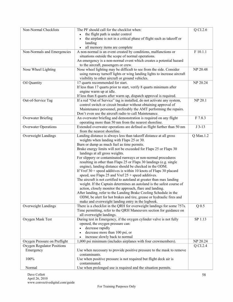
Dave Collett April 26, 2010 www.convectivedigital.com/guide
For Training Purposes Only
58
Non-Normal Checklists The PF should call for the checklist when: the flight path is under control the airplane is not in a critical phase of flight such as takeoff or
landing all memory items are complete
Q CI.2.6
Non-Normals and Emergencies A non-normal is an event created by conditions, malfunctions or situations outside the scope of normal operations.
An emergency is a non-normal event which creates a potential hazard to the aircraft, passengers or crew.
F 10.1.1
Nose Wheel Lighting Nose wheel lighting may be difficult to see from the side. Consider using runway turnoff lights or wing landing lights to increase aircraft visibility to other aircraft or ground vehicles.
NP 20.48
Oil Quantity 17 quarts recommended for start. If less than 17 quarts prior to start, verify 8 quarts minimum after
engine warm up at idle. If less than 8 quarts after warm up, dispatch approval is required.
NP 20.24
Out-of-Service Tag If a red “Out of Service” tag is installed, do not activate any system, control switch or circuit breaker without obtaining approval of Maintenance personnel, preferably the AMT performing the repairs.
Don’t even use the aircraft radio to call Maintenance.
NP 20.1
Overwater Briefing An overwater briefing and demonstration is required on any flight operating more than 50 nm from the nearest shoreline.
F 7.8.3
Overwater Operations Extended overwater operations are defined as flight further than 50 nm from the nearest shoreline.
J 3-13
Overweight Landings Landing distance is always less than takeoff distance at all gross weights when landing with Flaps 25 or 30.
Burn or dump as much fuel as time permits. Brake energy limits will not be exceeded for Flaps 25 or Flaps 30
landings at all gross weights. For slippery or contaminated runways or non-normal procedures
resulting in other than Flaps 25 or Flaps 30 landings (e.g. single engine), landing distance should be checked in the ODM.
If Vref 30 + speed additives is within 10 knots of Flaps 30 placard speed, use Flaps 25 and Vref 25 + speed additives.
The aircraft is not certified to autoland at greater than max landing weight. If the Captain determines an autoland is the safest course of action, closely monitor the approach, flare and landing.
After landing, refer to the Landing Brake Cooling Schedule in the ODM, be alert for hot brakes and tire, grease or hydraulic fires and make and overweight landing entry in the logbook.
Q Man.1.2
Overweight Landings There is a checklist in the QRH for overweight landings for some 757s. Time permitting, refer to the QRH Maneuvers section for guidance on
all overweight landings.
Q 0.5
Oxygen Mask Test During test in Emergency, if the oxygen cylinder valve is not fully opened, the oxygen pressure can: decrease rapidly decrease more than 100 psi, or increase slowly back to normal
SP 1.13
Oxygen Pressure on Preflight 1,000 psi minimum (includes airplanes with four crewmembers). NP 20.24 Oxygen Regulator Positions Emergency 100% Normal
Use when necessary to provide positive pressure to the mask to remove
contaminants. Use when positive pressure is not required but flight deck air is
contaminated. Use when prolonged use is required and the situation permits.
Q CI.2.4

Dave Collett April 26, 2010 www.convectivedigital.com/guide
For Training Purposes Only
59
Oxygen Requirements One Pilot in the Seat Both Pilots in the Seats Cabin above 10,000 feet
Seated pilot will use oxygen when above FL 250. One pilot will use oxygen when above FL 410. All pilots will use oxygen.
F 3.4.10
PA Quiet Hours 10 p.m. to 8 a.m. (local). When top of climb to top of descent is over 5 hours.
F 7.8.3
Packs and Bleeds Do not use the APU for bleed air with anti-ice on. Operating both packs from a single engine bleed source is acceptable
except during icing conditions. During single-engine taxi with anti-ice on, operate only one pack (with
the APU bleed valve closed and engine bleed valve open). During both single- and two-engine taxi, if environmental conditions
allow, operating only one pack will provide additional fuel savings.
NP 20.46
NP 20.47
Packs Off Takeoff Normally use the Packs Off Takeoff procedure for all airplanes if required to increase performance or to prevent EGT overtemps.
If needed, the 757 also has an APU to Pack Takeoff procedure for use at a few high elevation airports to prevent the cabin from exceeding 10,000' during takeoff and initial climbout. This is a rare situation and, if used, ensure the APU On performance penalties are manually applied to the AWABS.
An ENG BLEED OFF message may display during takeoff roll. This indication is acceptable for Packs Off takeoffs.
SP 2.2
Parking Brake When the wind, including gusts, exceeds 30 knots or if the ramp is icy, leave the parking brake set at the gate.
F 6.1.9
Passenger Baggage Do not store any item belonging to a passenger in the cockpit. F 7.2.2 Passenger Deplaning During
IROPS Coordinate with the Flight Leader and gate agent and consider
deplaning if a delay is expected to exceed 40 minutes. F 7.1.12
Passenger Initiated Evacuation Upon being notified of a passenger initiated evacuation the Captain should: configure the aircraft for evacuation, if possible (engines) make a PA advising passengers the evacuation is not necessary
and to remain in their seats
F 10.1.6
Passenger Oxygen Do not activate the passenger oxygen system in a smoke or fumes situation. It mixes cabin air with oxygen so it will not help the passengers and it is an extreme fire hazard.
Q CI.2.18
Passenger Standing During Ground Movement
Bring the aircraft to a stop when it is safe to do so. F 7.1.6
Phone Patch Other than calls to ATC, once out of the gate, all operationally significant calls must be routed through Atlanta Radio for transcribing. Do not call Flight Control, Maintenance, etc., directly.
J 6-41

Dave Collett April 26, 2010 www.convectivedigital.com/guide
For Training Purposes Only
60
Pilot Responses Gnd Proximity Caution (Multiple Advisories) Gnd Proximity Warning (“Pull Up.” May include
“Obstacle” or “Terrain.”) Predictive Windshear Caution (“Monitor Radar Display”) Predictive Windshear
Warning on T/O (“Windshear Ahead,
Windshear Ahead”) Predictive Windshear
Warning on Approach (“Go-Around, Windshear
Ahead”) Windshear Indications Microburst Alert for Landing
Runway (Issued by ATC)
Correct the flight path or configuration Terrain Avoidance Maneuver Maneuver as required to avoid the windshear If prior to V1, abort the takeoff If after V1, perform the Windshear Escape Maneuver Windshear Escape Maneuver or normal go-around at pilot’s discretion Windshear Escape Maneuver Windshear indications include unacceptable flight path deviations
below 1,000' AGL in excess of: ± 15 kts indicated airspeed ± 500 fpm vertical speed ± 5 degrees of pitch 1 dot deviation from the glideslope unusual throttle position for a significant period of time and/or Windshear siren and “Windshear, Windshear, Windshear.”
Mandatory go-around. Windshear Escape Maneuver if flight path
becomes marginal.
Q Man.1.8
Q Man.1.9
Q Man.1.14
J 4-46
Post Accident or Incident After landing and clear of the runway or after a ground accident/incident resulting in substantial aircraft damage, pull the Cockpit Voice Recorder circuit breaker. Do not deactivate the Cockpit Voice Recorder in flight.
Do not make any statements to the public or press. Refer all questions to Corporate Communications.
Refer to the FOM for checklists and report submission requirements.
F 10.3.2
F 10.3.4
Precipitation Limits Do not take off during heavy freezing drizzle, heavy ice pellets, moderate or heavy freezing rain.
In flight, moderate to heavy rain, hail or sleet should be avoided to the maximum extent possible. If unavoidable, place the Engine Start Selectors to CONT.
SP 16.19
SP 16.56
PRM Breakout Procedures All breakouts must be hand-flown. Disengage the autopilot. The PM should turn off both flight directors. Maneuver as directed by ATC. If a controller breakout is accompanied by a TCAS RA: follow vertical guidance from TCAS follow horizontal guidance from the controller
Vertical speed should not exceed 1,000 fpm on a descending breakout.
NP 30.6

Dave Collett April 26, 2010 www.convectivedigital.com/guide
For Training Purposes Only
61
Procedure Turns (Domestic) Entry Airspeed Entry Turn Proceeding Outbound Descent 45°/180° Procedure Turn
Procedure Turns are not required when: receiving radar vectors to final approach flying a NoPT routing cleared for a straight-in approach cleared for approach from a holding pattern with the holding fix
collocated with the FAF and the holding course aligned with the final approach course
Maneuvering speed or holding speed, but not greater than 200 kts. Same as a holding pattern entry. Max angle for teardrop is 30°. If an entry turn in the shorter direction places the aircraft on the non-
maneuvering side, correct back to the procedure turn course using an intercept angle of at least 20 degrees.
If the inbound course is intercepted outbound, maintain course and turn inbound on the maneuvering side.
Use timing, DME, etc. to remain within the published distance. If timing, start timing outbound abeam the procedure turn fix or wings
level outbound if abeam cannot be determined. Begin descent from the procedure turn fix altitude when outbound
abeam the procedure turn fix or wings level outbound if the abeam point cannot be determined.
If flying a 45/180 procedure turn, begin descent from the IAF altitude when outbound abeam and on a parallel or intercept heading to the outbound track.
Descend from the procedure turn altitude or any altitude past the IAF when established on the appropriate published segment of the approach.
The 45°/180° course reversal is optional in U.S. airspace. Intercept and maintain the outbound track as soon as possible after
passing the procedure turn fix. To make the course reversal, fly outbound on the 45° leg for
45 seconds before turning inbound. Make the 180° turn back inbound as depicted.
Descend as necessary on the outbound track to the specified altitude. If further descent is necessary after the inbound turn, do not descend until established on the inbound track, which is defined as within half scale deflection on an ILS or VOR and within 5° on an NDB.
Maximum descent rates to guarantee obstacle clearance are: 1,197 fpm on the outbound track 755 fpm on the inbound track
J 3-104
J 3-105
Pushback Without Tug Communications
If the interphone communications are inop, the Captain and ramp agent will conduct a face-to-face review of hand signals to be used.
If the Captain requires an emergency stop he should flash the taxi light repeatedly until the aircraft comes to a complete stop.
F 6.1.1
Radar Contact on Departure “Radar contact” on departure does not mean the controller is providing obstacle clearance. Obstacle clearance begins when the controller starts giving navigational guidance.
AIM 5-2-8 c2

Dave Collett April 26, 2010 www.convectivedigital.com/guide
For Training Purposes Only
62
Radio and Baro Bugs CAT I ILS CAT II CAT II RA Not Auth CAT III Straight-In Non-ILS Circling Visual
Baro at published DA, Radio off Baro at field elevation, Radio at published RA Baro at published DA, Radio off Baro at field elevation, Radio at 50 feet Baro at published DA, DDA or MDA, Radio off Baro at higher of published MDA or field elevation + 1,000', Radio off Baro at published mins for the approach used to back up the visual
approach. Set field elevation if no approach is available. Radio off.
NP 20.60
Ram Air Turbine Deploys automatically inflight if both engines fail. Automatic deployment is inhibited on the ground, but manual
deployment is possible. Use caution. Powers the flight control portion of center hydraulic system only. Requires airspeed above 130 kts to maintain aircraft control.
II
Raw Data On all non-RNAV approaches pilots must monitor applicable raw data to determine course guidance and FMS map validity at the FAF.
One pilot must display raw data associated with the approach. Localizer course deviation may be monitored on the ADI. Localizer DME is monitored by selecting ILS or APP on the EFIS
Control Panel. VOR or NDB course raw data may be monitored on the RDMI. If
desired, VOR course and DME raw data may be monitored by selecting VOR on the EFIS Control Panel.
For non-ILS or ILS-G/S Out approaches, raw data monitoring of the MAP is not required due to the accuracy of FMC positioning
SP 4.9
SP 4.13
Raw Data On ILS-DME approaches, one pilot must select ILS or APP (not Map) on his EFIS control panel to display DME from the localizer on the RDMI to legally fly the approach.
To monitor raw data on a VOR approach, select Manual on the VOR control panel and tune the correct VOR frequency. This prevents the FMS from auto-tuning the VOR to another station. You can then monitor raw data on either the RDMI or the HSI with VOR selected on the EFIS control panel.
For DME distances to a VOR station, it is also necessary to select Manual on the VOR control panel and manually tune the VOR frequency to force the appropriate DME to the RDMI and prevent the VOR from auto-tuning to another station.
Selecting Manual on the VOR panel will cause the tuned VOR station and the selected course to be displayed on the map. This is not raw data. It’s just a computer-generated display based on FMS position. If the FMS position is wrong, the display will be wrong. To actually check raw data, use the RDMI or select VOR mode and dial in the desired course.
On NDB approaches, make sure the NDB is tuned and the left VOR/ADF selector on the RDMI is in ADF.
GS
Resume Normal Speed “Resume Normal Speed” from ATC means that any previously issued speed adjustment is removed and the pilot is cleared to fly the published speed on the route (STAR, SID, etc.) or, if there is no published speed, any speed desired as long as it complies with FAR speed limits.
GS
Revising an ETA Advise ATC when the ETA given is in error by three minutes or more. Not required in the US when in radar contact.
J 6-21

Dave Collett April 26, 2010 www.convectivedigital.com/guide
For Training Purposes Only
63
RNAV Departure Ensure any critical DMEs identified in the procedure are operative unless the aircraft has GPS. Critical DMEs do not apply if GPS is operative.
For non-GPS aircraft with the autothrottle or N1/EPR switch inop, consider a Fast Realignment of the IRSs immediately prior to pushback.
All Non-Pegasus Airplanes (no GPS) when approaching the departure runway, check aircraft position
versus runway position on the HSI 10 nm scale if the autothrottles or N1/EPR switch are inop, the FMS will not
update the aircraft’s position to the landing runway threshold. In this case, verify the aircraft symbol is in close proximity to the departure end of the runway symbol with the HSI in the 10 nm scale.
if the aircraft map position is greater than 1,000 feet from the actual runway takeoff position, or cannot be determined, do not accept an RNAV departure and request radar vectors to the first fix
the FMS will begin searching for suitable radio updates after the aircraft reaches 100 knots on takeoff roll
If the departure procedure and clearance require an LNAV track from
the runway, arm LNAV before takeoff. Listen carefully to the takeoff clearance. “Delta 1234, cleared for
takeoff” is the standard clearance to fly the published RNAV SID assigned by Clearance Delivery or on the PDC. If not cleared for the RNAV departure, the takeoff clearance will include a heading to fly or some other clearance. (In ATL and DFW, the takeoff clearance for an RNAV departure will include the first RNAV fix, e.g. “Delta 1234, RNAV to FUTBL, runway 27R, cleared for takeoff”).
Use of the autopilot is highly encouraged. Engage it at 1,000' AFE after LNAV and VNAV are engaged.
Expect the FMS to use turn anticipation for fly-by waypoints (waypoints on the chart without a circle around them).
RNAV SIDs and STARs are based on maintaining path accuracy within 0.5 nm. On the HSI 10 nm scale, the base of the airplane symbol is approximately 1 nm across and pilots may use the airplane symbol or the Progress page to monitor the path.
SP 11.52
SP 11.53
SP 11.54
Rudder Effectiveness The rudder becomes effective at between 40 and 60 knots on takeoff and is effective until approximately 60 knots on landing.
T 3.6 T 6.28
Rudder Trim on Single Engine In flight, correct rudder input approximately centers the control wheel. T 3.37 Runway Change Items A ■ indicates items on the checklists that should be considered for re-
accomplishment in the event of a runway change. If the landing runway is changed and the Captain determines the
runway change can be accomplished visually, the runway change items may be waived.
Q CI.1.4
Runway Definitions A dry runway is a runway that is dry and the visibility is RVR 4000/ ¾ sm or greater.
A wet runway is a runway that is wet or the visibility is less than RVR 4000/ ¾ sm. The ARM refers to this as wet/low minima.
A short runway is a runway less than 7,000 feet for 757-300 and 767 aircraft and less than 6,000 feet for 757-200 aircraft. The Captain must discuss the situation with the Dispatcher unless there is guidance on the Delta Special Page.
F 5.1.1

Dave Collett April 26, 2010 www.convectivedigital.com/guide
For Training Purposes Only
64
Runway Dependent STAR Runway Dependent STARs require the pilot to select a specific runway in order for the FMC to properly load the entire STAR.
The entire loading procedure must be re-accomplished if the runway or arrival changes to prevent an incorrect routing or inadequate obstacle clearance.
SP 11.24
Runway Edge Lights Runway edge lights are required for all takeoff and landing operations: between sunset and sunrise (night) between sunrise and sunset (day) when the visibility is reported
less than 2 statute miles.
J 3-6
Runway Heading Magnetic heading of the runway centerline, not the runway number. AIM PCG Runway Use After Snow
Plowing Takeoff on runways that have been plowed is authorized provided the
runway is plowed at least 50 feet on both sides of the centerline and snow or ice outside the plowed area but within 75 feet of the centerline is no more than 6 inches high.
F 5.1.3
Runway Width The minimum runway width is 148 feet (45 meters). F 5.1.3 Seat Belt and No Smoking
Signs Flight attendants may leave their seats after takeoff before the seat belt
sign is turned off unless the Captain has informed them to remain seated until advised.
If the seat belt sign is turned on in flight, the flight attendants should be notified if it is necessary for them to be seated.
A customer service PA should be made if the flight attendants are required to remain seated for an extended period.
F 3.4.12
F 3.3.6
Secure Checklist Accomplish the Secure Checklist only when: requested by Maintenance or Operations the aircraft is to remain for two hours or more, or the aircraft is to remain overnight
Perform a post flight walk around if at a limited or non-maintenance station.
NP 20.73
Sequenced Flashers Not required for any domestic approach, but may be required in some foreign countries for some approaches.
J 3-38
Serious Passenger Misconduct Serious passenger misconduct is defined as injuring another passenger or crew member, subjecting a passenger or crew member to a credible threat of injury, interfering with a crew member’s duties, or refusing to comply with Federal regulations.
F 7.3.1
Sidestep Approaches The landing runway must not be more than 1,200 feet from the approach runway.
If the sidestep is a published instrument approach procedure there will be weather minimums on the approach plate.
If the sidestep is an informal maneuver it must be conducted in VMC and with the agreement of both ATC and the aircrew.
Any time an aircraft is flying an instrument approach in IMC and plans to land on another runway it is considered a circling approach unless sidestep minimums are published for the runway of intended landing.
J 3-112
SMGCS Some procedures may take effect at RVR 1200 even though a SMGCS chart is only required below RVR 500.
The SMGCS chart, if available, should be referenced for any CAT III approach and for any taxi out for takeoff when the visibility is reported below RVR 1200.
If the visibility is below RVR 500, the ATIS will state that low visibility procedures are in progress and pilots will notify ATC of their approach minima.
At no time will a pilot cross an illuminated red stop bar.
J 3-91
J 3-93 SMGCS Taxi Lines Yellow taxi lines painted on taxiways used for SMGCS movement are
12 inches wide and highlighted in black paint. GS
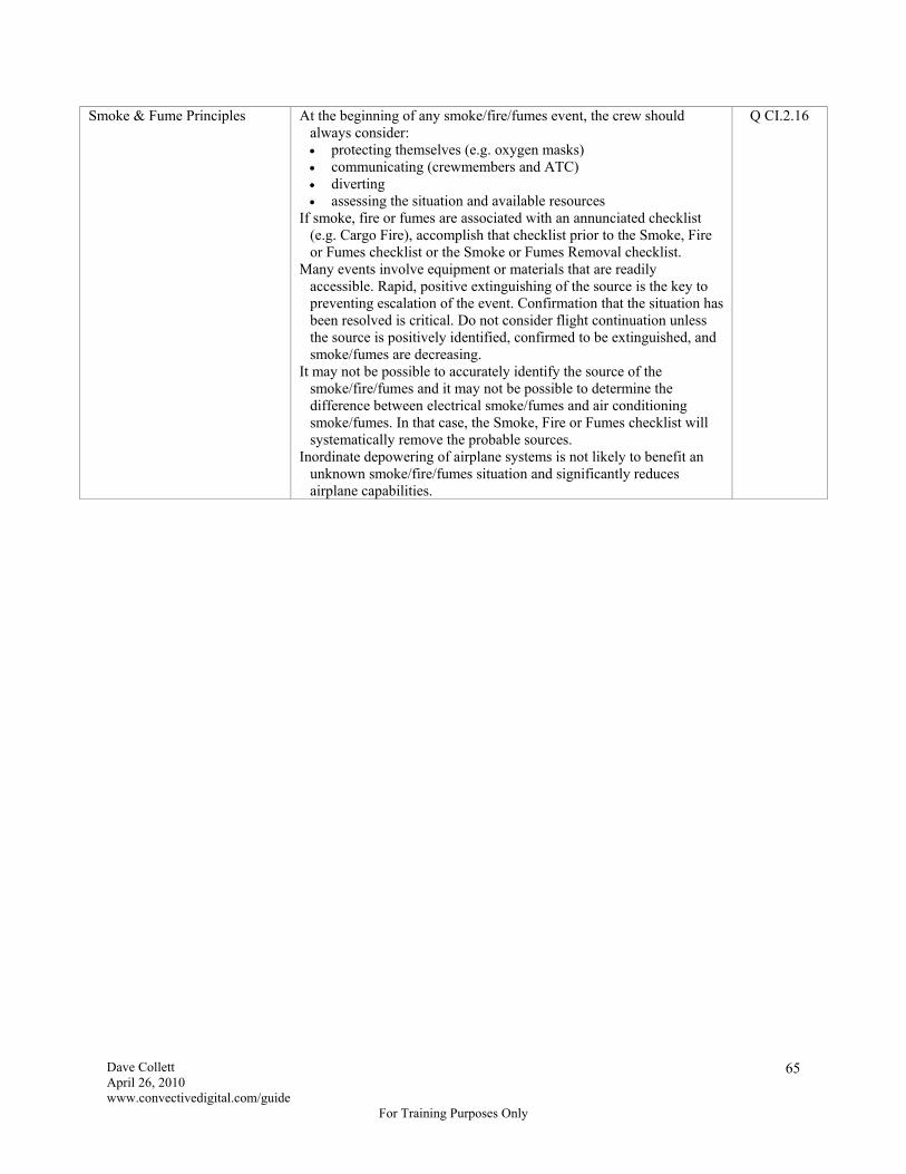
Dave Collett April 26, 2010 www.convectivedigital.com/guide
For Training Purposes Only
65
Smoke & Fume Principles At the beginning of any smoke/fire/fumes event, the crew should always consider: protecting themselves (e.g. oxygen masks) communicating (crewmembers and ATC) diverting assessing the situation and available resources
If smoke, fire or fumes are associated with an annunciated checklist (e.g. Cargo Fire), accomplish that checklist prior to the Smoke, Fire or Fumes checklist or the Smoke or Fumes Removal checklist.
Many events involve equipment or materials that are readily accessible. Rapid, positive extinguishing of the source is the key to preventing escalation of the event. Confirmation that the situation has been resolved is critical. Do not consider flight continuation unless the source is positively identified, confirmed to be extinguished, and smoke/fumes are decreasing.
It may not be possible to accurately identify the source of the smoke/fire/fumes and it may not be possible to determine the difference between electrical smoke/fumes and air conditioning smoke/fumes. In that case, the Smoke, Fire or Fumes checklist will systematically remove the probable sources.
Inordinate depowering of airplane systems is not likely to benefit an unknown smoke/fire/fumes situation and significantly reduces airplane capabilities.
Q CI.2.16

Dave Collett April 26, 2010 www.convectivedigital.com/guide
For Training Purposes Only
66
Smoke & Fume Priorities The following information is critical for survival in a smoke/fumes situation.
Pilots should remain at their stations. Crews are reminded that after making a preliminary assessment of the
situation, a diversion may be necessary. The flight crew should don oxygen masks any time smoke/fire/fumes
are detected on the flight deck. If smoke/fire/fumes are detected in other parts of the aircraft, crew judgment will determine if oxygen masks are necessary.
For smoke/fire/fumes in the cabin, continuous communication with a designated flight attendant is essential. Flight attendants should inspect the entire cabin to locate the source and report it to the pilots. Move passengers away from the source.
Without delay or analysis, perform the initial steps of the Smoke, Fire or Fumes checklist to remove the most probable sources.
Once a fire or a concentration of smoke/fumes is detected, continuing the flight to the destination is not recommended unless the source is positively identified, visually confirmed to be extinguished and the smoke/fumes are decreasing. If the initial steps of the checklist do not positively identify and remove the smoke/fumes, a diversion is necessary.
“Visually confirmed to be extinguished” means that a crewmember can see the source and that it has been extinguished. For example, smoke coming from an oven that stops after power is removed is a situation where the source is visually confirmed to be extinguished. On the other hand, if smoke stops after depowering a system (e.g. a recirc fan) the source is not “positively identified and visually confirmed to be extinguished” and a diversion is necessary.
The flight crew must continually evaluate the situation to determine if further actions are necessary.
Complete the Smoke or Fumes Removal checklist only when the smoke/fumes are the greatest threat or after the source is confirmed to be extinguished. This checklist may make the situation worse by fanning or masking the ignition source.
Do not activate the passenger oxygen system. It mixes cabin air with oxygen so it will not help the passengers and it is an extreme fire hazard.
Q CI.2.17
Smoke, Fire or Fumes Checklist Unless smoke, fire or fumes are associated with an annunciated checklist (e.g. Cargo Fire), start with the Smoke, Fire or Fumes checklist. Do not start with the Smoke or Fumes Removal checklist.
If directed to the Smoke or Fumes Removal checklist, do not delay landing to complete it.
Q 8.10
Q 8.30
Snow or Ice on Runway If there is snow or ice on the runway, no flight may take off or land without a current field condition report or braking action report.
F 5.1.3
Special VFR Not authorized. J 3-72 Special Winter Operations
Airports Certain airports are designated as Special Winter Operations Airports
(SWOA) and have additional restrictions when snow, ice or slush is on the runway or if freezing precipitation is falling and accumulating. Refer to the flowchart in Jepps Chapter 4 for details.
J 4-50
Speed Intervention Speed intervention may cause a loss of VNAV PATH during descent, resulting in a violation of a crossing restriction altitude.
SP 4.3
Speed Intervention The FMC does not use the speed set on the MCP for fuel or ETA predictions so FMC predictions are not accurate if speed intervention is used for an extended period of time.
II
Speedbrake Arming Arming the speedbrake prior to landing is required by checklist. NP 20.63

Dave Collett April 26, 2010 www.convectivedigital.com/guide
For Training Purposes Only
67
Speedbrake Retraction Use caution when retracting the speedbrakes close to Vmo/Mmo or a flap limit speed. The airplane will accelerate after retraction and may overspeed the airframe or flaps.
GS
Speedbrakes on Blended Winglet Airplanes
On blended winglet airplanes, speedbrakes may automatically retract to the 50% position when airspeed exceeds 330 knots (757) or 320 knots (767). If this occurs, do not extend the speedbrake lever beyond the 50% position until airspeed is less than 325 knots (757) or 315 knots (767).
Q 2.2
Sports Scores When you request sports scores from ATLXGDL, be sure to use the word “scores” in the message. If you do, the message will be automatically routed to Atlanta Radio operators who will provide the scores. If you don’t, the message will only go to the Dispatcher who will have to forward it.
GS
Spring-Loaded Latch A bronze-colored spring-loaded safety latch is required for galley carts in the aft galley that could roll down the aisle if not restrained.
GS
Stabilized Approach At 1,000 feet AGL At 500 feet AGL At 100 feet HAT Crossing Runway Threshold
Configured for landing. Maintaining a stabilized descent rate not to exceed 1,000 fpm unless a
published approach procedure requires a sink rate greater than 1,000 fpm and a special briefing was conducted.
If IMC, on target airspeed or reducing toward it. If IMC, established on course. On target airspeed within tolerance (-5/+10 knots) Engines stabilized at the thrust setting required to maintain the desired
airspeed and descent rate. If VMC, lined up with the runway unless local procedures dictate
otherwise. The cockpit must be tracking so as to remain within the lateral confines
of the extended runway. Stabilized on target airspeed within tolerance. On a stabilized flight path. Positioned to make a normal landing within the touchdown zone.
NP 30.4
Standard Takeoff Minimums RVR 5000 (1500 m) or 1 statute mile (1600 m) J 3-21 Standby Power Consider that a normal descent from cruise altitude takes about 25
minutes and the battery will only last about 30 minutes after an electrical failure. An expeditious descent and divert might be wise.
GS
Standby Power Check Required prior to the first flight of the day. The aircraft must be on the ground with all busses powered. Standby Power Selector – BAT. Observe the battery DISCH light (APU BAT DISCH and MAIN
BAT DISCH lights on 757-300 aircraft) illuminates and the standby power OFF light remains extinguished
Standby Power Selector – AUTO. Observe the battery DISCH light (APU BAT DISCH and MAIN
BAT DISCH lights on 757-300 aircraft) extinguishes and the standby power OFF light remains extinguished
SP 6.6

Dave Collett April 26, 2010 www.convectivedigital.com/guide
For Training Purposes Only
68
Step Down Altitudes on Approaches
When cleared for an ILS approach, you may not descend below the step-down altitudes prior to the FAF. In some cases, following the glideslope prior to the “feather” will take you below step-down altitudes and may result in a violation or unsafe terrain clearance. A good technique is to fly the localizer while complying with the step-down altitudes with VNAV, V/S or Flight Level Change and then arm Approach mode at the feather. If you do intercept the glideslope prior to the feather, use raw data to ensure compliance with the step-down altitudes and deviate from the glideslope if necessary.
When cleared for a visual approach to an airport in Class B airspace, you must remain above the floor of the Class B during the approach. In some cases, following the ILS glideslope prior to the feather will take you out the bottom of the Class B and, once again, may result in a violation. (LAS 25L/R and SLC 16L are two examples.) Therefore, even on a visual approach, ensure compliance with the step-down altitudes on the ILS approach plate. (Refer to the Visual Approach section in Ops Specs.)
Class B airspace is depicted on low altitude charts and area charts.
GS
Sterile Cockpit Crew members will only conduct activities related to the safe operation of the aircraft during critical phases of flight (pushback, taxi, takeoff, landing and flight below 10,000' AFE).
When the aircraft is stopped during taxi, PAs promoting public relations are permissible.
F 3.2.16
Supplementary Procedures At the discretion of the Captain, procedures in the Supplementary Procedures section may be completed by recall, by reviewing the procedure prior to accomplishment, or by reference to the procedure during accomplishment.
SP 05.1
Tailstrike on Takeoff Do not pressurize the airplane due to possible structural damage. Q 0.0 Takeoff A standing takeoff is required whenever engine anti-ice is on.
The Captain will make a static takeoff whenever the visibility is below RVR 1600.
SP 16.8 J 3-4
Takeoff Do not turn below 400 feet AFE unless specified in the published departure procedure or specifically cleared by ATC.
Some engine-out procedures require a turn at a specified distance and may therefore require a turn below 400 feet AFE.
J 3-11
Takeoff For an immediate turn after takeoff, maintain initial climb speed with takeoff flaps while maneuvering. Follow AFDS bank limits.
NP 30.16
Takeoff Rolling – maintain normal taxi speed while entering the runway. When the airplane is aligned with the centerline, release the nosewheel tiller and apply thrust. There is no need to stop.
Static – stop the airplane aligned with the centerline, release the nosewheel tiller, release brakes and apply thrust. There is no need to hold the brakes while applying thrust. This satisfies the requirement for a static takeoff during low visibility.
Standing – align the airplane with the centerline, release the nosewheel tiller and hold the brakes while advancing power to at least 60% N1. When the engines are stabilized, release brakes and promptly advance thrust levers to takeoff thrust. This takeoff is required if engine anti-ice is on.
T 3.5
Takeoff When an immediate turn after takeoff is necessary, the desired heading may be preset on the MCP before takeoff.
T 3.33
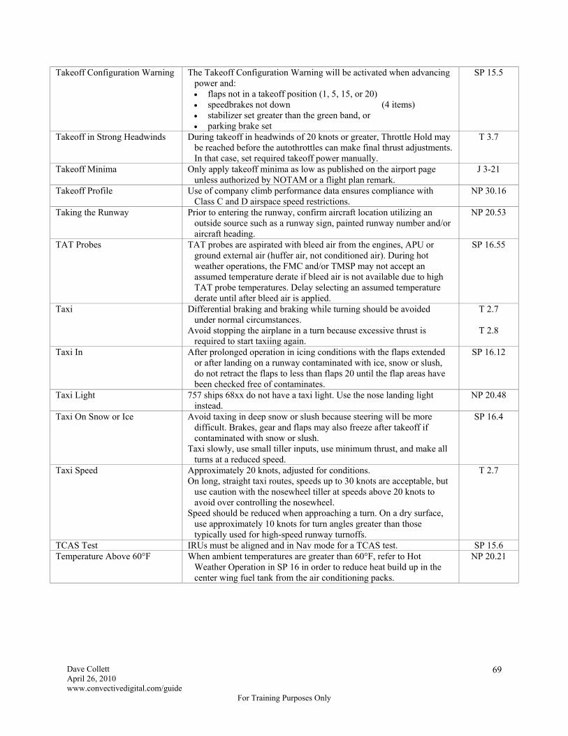
Dave Collett April 26, 2010 www.convectivedigital.com/guide
For Training Purposes Only
69
Takeoff Configuration Warning The Takeoff Configuration Warning will be activated when advancing power and: flaps not in a takeoff position (1, 5, 15, or 20) speedbrakes not down (4 items) stabilizer set greater than the green band, or parking brake set
SP 15.5
Takeoff in Strong Headwinds During takeoff in headwinds of 20 knots or greater, Throttle Hold may be reached before the autothrottles can make final thrust adjustments. In that case, set required takeoff power manually.
T 3.7
Takeoff Minima Only apply takeoff minima as low as published on the airport page unless authorized by NOTAM or a flight plan remark.
J 3-21
Takeoff Profile Use of company climb performance data ensures compliance with Class C and D airspace speed restrictions.
NP 30.16
Taking the Runway Prior to entering the runway, confirm aircraft location utilizing an outside source such as a runway sign, painted runway number and/or aircraft heading.
NP 20.53
TAT Probes TAT probes are aspirated with bleed air from the engines, APU or ground external air (huffer air, not conditioned air). During hot weather operations, the FMC and/or TMSP may not accept an assumed temperature derate if bleed air is not available due to high TAT probe temperatures. Delay selecting an assumed temperature derate until after bleed air is applied.
SP 16.55
Taxi Differential braking and braking while turning should be avoided under normal circumstances.
Avoid stopping the airplane in a turn because excessive thrust is required to start taxiing again.
T 2.7
T 2.8
Taxi In After prolonged operation in icing conditions with the flaps extended or after landing on a runway contaminated with ice, snow or slush, do not retract the flaps to less than flaps 20 until the flap areas have been checked free of contaminates.
SP 16.12
Taxi Light 757 ships 68xx do not have a taxi light. Use the nose landing light instead.
NP 20.48
Taxi On Snow or Ice Avoid taxing in deep snow or slush because steering will be more difficult. Brakes, gear and flaps may also freeze after takeoff if contaminated with snow or slush.
Taxi slowly, use small tiller inputs, use minimum thrust, and make all turns at a reduced speed.
SP 16.4
Taxi Speed Approximately 20 knots, adjusted for conditions. On long, straight taxi routes, speeds up to 30 knots are acceptable, but
use caution with the nosewheel tiller at speeds above 20 knots to avoid over controlling the nosewheel.
Speed should be reduced when approaching a turn. On a dry surface, use approximately 10 knots for turn angles greater than those typically used for high-speed runway turnoffs.
T 2.7
TCAS Test IRUs must be aligned and in Nav mode for a TCAS test. SP 15.6 Temperature Above 60°F When ambient temperatures are greater than 60°F, refer to Hot
Weather Operation in SP 16 in order to reduce heat build up in the center wing fuel tank from the air conditioning packs.
NP 20.21

Dave Collett April 26, 2010 www.convectivedigital.com/guide
For Training Purposes Only
70
Terrain Alerts During RNP Operations
During low RNP operations (RNP less than 0.3), crews may experience momentary caution-level terrain alerts. If these alerts are of short duration and have ceased, crews should verify they are on the correct path and consider continuing the approach in LNAV and VNAV. The risks of terrain contact during the terrain avoidance maneuver may be higher than continuing on the required track.
Warning-level terrain alerts always require immediate action. The most appropriate action depends on where the terrain avoidance maneuver is initiated.
T 7.25
Thrust Reverser Movement of the reverse thrust lever could result in operation of the engine thrust reverser even with the engine shut down.
NP 20.25
Thrust Reversers on Landing After reverse thrust is initiated, a full stop landing must be made. Initiate movement toward reverse idle by 80 knots and reach the
reverse idle detent prior to taxi speed. The PM should call “80 knots.”
Stow the thrust reversers after the engines have decelerated to idle.
NP 20.65
Thunderstorms Enroute
Do not operate through an area of thunderstorms unless separations between individual thunderstorm cells are at least: 5 miles if below 10,000 feet 10 miles if between 10,000 and 25,000 feet 20 miles if at or above 25,000 feet
Avoid flying directly over the top of a thunderstorm cell within 5,000 feet of the radar return.
When possible, detour between the cells of a squall line rather than over them.
Deviate upwind when possible. Turbulence can be expected downwind from the storm 1 nm for each
knot of wind at altitude. To avoid hail, do not fly under the anvil or in cirrus or cirrostratus
layers downwind of the storm top. Hail has been encountered as much as 20 miles downwind from large
thunderstorms.
J 4-42
J 4-43
Thunderstorms Near Airport Delay or conduct the departure or arrival from a different direction if significant thunderstorm activity is within 15 miles of the airport.
Takeoffs and landings will not be attempted when a thunderstorm is within 3 miles of the intended flight path. Special consideration should be given to delaying or diverting when heavy rain associated with a thunderstorm is within the airport boundary or on the approach or departure path.
J 4-42
Touchdown Zone The first 3,000 feet or first third of the runway, whichever is less. NP 30.5 Touchdown Zone Elevation
(TDZE) The highest elevation in the first 3,000 feet of the landing surface. J 13
Transition Altitude and Transition Level
Transition altitude is the altitude climbing through which the altimeters must be set to 29.92 or 1013 (QNE).
Transition level is the flight level descending through which the altimeters must be reset to the local altimeter setting (QNH).
J 3-51
Transition Altitude and Transition Level Callouts
“Altimeters set to 29.92” when approaching transition altitude on climbout and “Altimeters set to _____” when approaching transition level on descent are required callouts in addition to the altimeter settings in the Climb and Descent checklists.
NP 10.13
Transponder Codes Emergency Radio Failure Unlawful Interference Oceanic
7700 7600 (do not squawk 7700 first for simple lost comm) 7500 2000 (except in WATRS, see LA(H/L) 5/6 chart)
J 3-17

Dave Collett April 26, 2010 www.convectivedigital.com/guide
For Training Purposes Only
71
Transponder Source Selector During preflight, set 1 or L if the left or center autopilot will be used and set 2 or R if the right autopilot will be used.
NP 20.27
Turbulence An encounter with severe or extreme turbulence requires a logbook entry and a special aircraft structural inspection.
J 4-32
Turbulence LeHi – if the aircraft is drifting left it indicates you are flying toward a high pressure ridge and the tropopause is climbing. Descend to avoid or minimize tropopause turbulence.
RiLo – if the aircraft is drifting right it indicates you are flying toward a low pressure trough and the tropopause is descending. Climb to avoid or minimize tropopause turbulence.
GS
Turbulence The autopilot may remain engaged during light to moderate turbulence unless airspeed, altitude or attitude deviations require manual control.
Normally fly the turbulent air penetration speed (290 kts/.78 M, whichever is less), but below 10,000 feet MSL a speed of 240-250 knots provides adequate buffet margin.
Severe turbulence should be avoided if at all possible, but if it cannot be avoided, descending approximately 4,000 feet below optimum altitude will increase buffet margin.
Autothrottles should be off in severe turbulence.
SP 16.57
Turbulence When dealing with turbulence associated with westerly jet stream winds: consider changing altitude or course if the wind is a headwind or
tailwind maintain course if the wind is a crosswind and consider climbing
if OAT is rising and descending if OAT is decreasing
GS
Turbulence Notification Pilots will make a PA when the seat belt sign is turned on. When encountering or anticipating moderate or severe turbulence,
direct the flight attendants to discontinue cabin service and be seated.
F 3.3.5
Unacceptable Passengers Unacceptable passengers include those: whose behavior indicates they may be hazardous to other
passengers who refuse to permit a search of their person or property for
explosives or weapons who are unruly, obnoxious or disorderly who appear to be intoxicated or under the influence of drugs who are not wearing some type of footwear who are naked above the waist who are stretcher patients who refuse to produce positive identification who have a malodorous condition unless due to disability
F 7.1.1
Unaccompanied Passenger Baggage
Convene the Security Conflict Team if a security concern arises. On domestic flights, baggage may travel unaccompanied provided a
TSA-approved screening method or a provision of Delta’s security program has been applied.
On international flights, a positive passenger/checked baggage match will be accomplished in addition to other forms of screening. Baggage of passengers involuntarily denied boarding may remain on the aircraft, but baggage of passengers removed from the flight or denied boarding for other reasons (e.g. abusive, medical, etc.) should be removed.
F 7.2.2 F 7.2.3
University of Pittsburgh Medical Center
On WiFi equipped airplanes, the flight attendants have the capability to connect directly to UPMC through Atlanta Radio using the Aircell phone service.
UPMC is the primary source of medical guidance. Onboard medical assistance should be considered secondary.
F 7.4.1
F 7.4.2

Dave Collett April 26, 2010 www.convectivedigital.com/guide
For Training Purposes Only
72
Unoccupied Jumpseats At each unoccupied seat, the safety belt and non-retracting shoulder harness, if installed, must be secured so as not to interfere with crew members in the performance of their duties. (Fasten the seat belt on the jumpseat when not being used.)
FAR 121.311
Unreliable Airspeed Indicator Differing from the standby airspeed indicator by more than 15 knots. Additional evidence is listed in the Airspeed Unreliable checklist in the
QRH.
Q 10.2
Unruly Passengers Pilots will not leave the cockpit to deal with passenger problems. F 7.3.1 Unscheduled Pressurization Do not leave the airplane unattended with a pack operating and all
doors closed. Accidental closure of the outflow valve can cause unscheduled pressurization. (Pop!)
SP 16.15
Valve Lights All Valve lights in the cockpit indicate a disagreement between the valve position and the commanded position.
GS
VASIs and PAPIs Two-Bar VASI Three-Bar VASI PAPI
Two-bar VASI systems are not recommended. Red over white is low. Red over two whites is on glidepath. Two white and two red is on glidepath.
T 6.4
Vertical Speed Mode No automatic low speed (stall) protection and permits flight away from the selected altitude. Always select a new level off altitude prior to engaging Vertical Speed mode.
SP 4.3
VFR Climb If specific VFR climb procedures are not published on the Delta Special Page, a VFR climb may only be requested after takeoff when the aircraft is cleaned up and accelerating, and when 2,000 feet terrain separation can be ensured.
VFR conditions and cloud clearances must be maintained throughout the climb.
Pilots are responsible for: VFR traffic avoidance ensuring terrain and obstacle clearance any restriction issued by ATC intercepting the route of flight during or after completing the
VFR climb
J 3-71
VFR Pattern Left traffic at 1,500' AFE unless otherwise specified. J 3-64 VHF Guard Monitoring In general, unless needed for ATC or Company communications,
monitor 121.5 on VHF radio #2. J 6-46
Visibility If RVR or RVV is reported, it controls for the specified runway. If RVR or RVV is not reported, use Prevailing Visibility.
J 3-4
Visibility On all approaches, if the aircraft is established on the final approach segment and the controlling visibility decreases below the authorized minima, the approach may be continued to the applicable AH/DH/MDA for the approach being conducted.
Specific foreign country exceptions may apply.
J 3-33 J 3-37 J 3-39
Visibility Prevailing Visibility – the greatest horizontal visibility equaled or exceeded throughout at least half the horizon circle which need not necessarily be continuous.
Runway Visibility Value (RVV) – the visibility determined for a particular runway by a transmissometer. The meter provides a continuous indication of the visibility (reported in miles or fractions of miles) for the runway.
Runway Visual Range (RVR) – an instrumentally derived value that represents the horizontal distance a pilot will see down the runway from the approach end. RVR, in contrast to prevailing visibility and RVV, is based on what a pilot in a moving aircraft should see looking down the runway.
AIM PCG
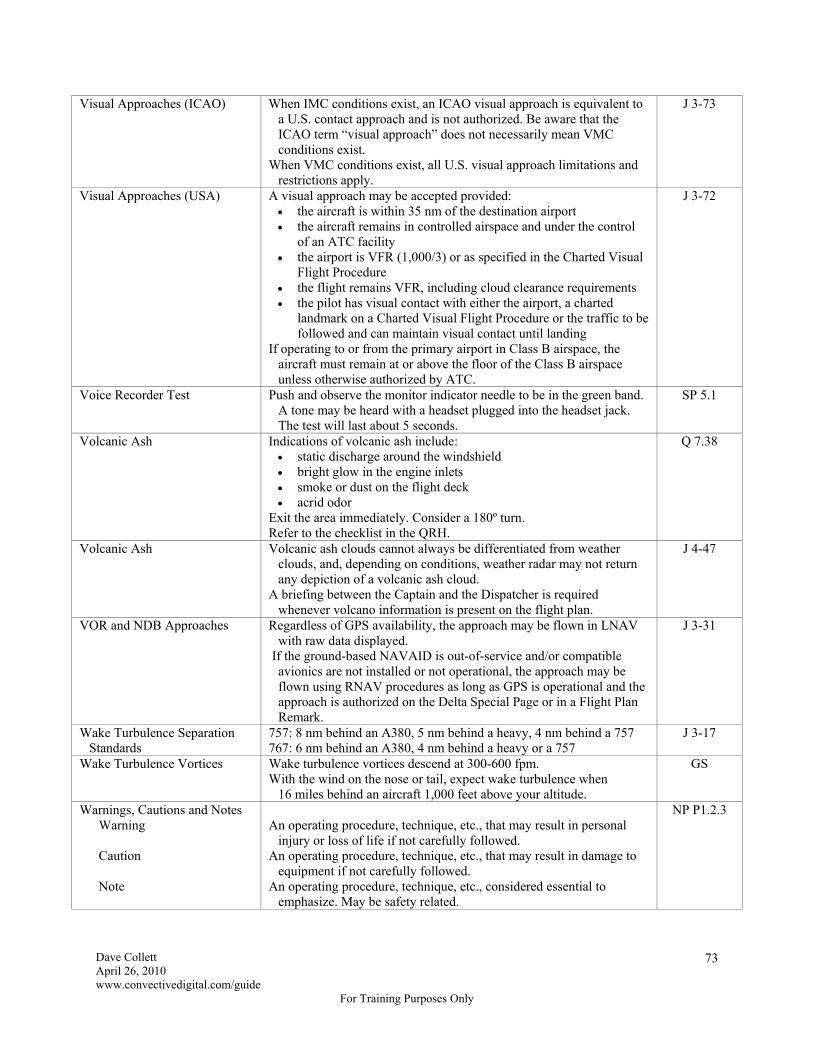
Dave Collett April 26, 2010 www.convectivedigital.com/guide
For Training Purposes Only
73
Visual Approaches (ICAO) When IMC conditions exist, an ICAO visual approach is equivalent to a U.S. contact approach and is not authorized. Be aware that the ICAO term “visual approach” does not necessarily mean VMC conditions exist.
When VMC conditions exist, all U.S. visual approach limitations and restrictions apply.
J 3-73
Visual Approaches (USA) A visual approach may be accepted provided: the aircraft is within 35 nm of the destination airport the aircraft remains in controlled airspace and under the control
of an ATC facility the airport is VFR (1,000/3) or as specified in the Charted Visual
Flight Procedure the flight remains VFR, including cloud clearance requirements the pilot has visual contact with either the airport, a charted
landmark on a Charted Visual Flight Procedure or the traffic to be followed and can maintain visual contact until landing
If operating to or from the primary airport in Class B airspace, the aircraft must remain at or above the floor of the Class B airspace unless otherwise authorized by ATC.
J 3-72
Voice Recorder Test Push and observe the monitor indicator needle to be in the green band. A tone may be heard with a headset plugged into the headset jack. The test will last about 5 seconds.
SP 5.1
Volcanic Ash Indications of volcanic ash include: static discharge around the windshield bright glow in the engine inlets smoke or dust on the flight deck acrid odor
Exit the area immediately. Consider a 180º turn. Refer to the checklist in the QRH.
Q 7.38
Volcanic Ash Volcanic ash clouds cannot always be differentiated from weather clouds, and, depending on conditions, weather radar may not return any depiction of a volcanic ash cloud.
A briefing between the Captain and the Dispatcher is required whenever volcano information is present on the flight plan.
J 4-47
VOR and NDB Approaches Regardless of GPS availability, the approach may be flown in LNAV with raw data displayed.
If the ground-based NAVAID is out-of-service and/or compatible avionics are not installed or not operational, the approach may be flown using RNAV procedures as long as GPS is operational and the approach is authorized on the Delta Special Page or in a Flight Plan Remark.
J 3-31
Wake Turbulence Separation Standards
757: 8 nm behind an A380, 5 nm behind a heavy, 4 nm behind a 757 767: 6 nm behind an A380, 4 nm behind a heavy or a 757
J 3-17
Wake Turbulence Vortices Wake turbulence vortices descend at 300-600 fpm. With the wind on the nose or tail, expect wake turbulence when
16 miles behind an aircraft 1,000 feet above your altitude.
GS
Warnings, Cautions and Notes Warning Caution Note
An operating procedure, technique, etc., that may result in personal
injury or loss of life if not carefully followed. An operating procedure, technique, etc., that may result in damage to
equipment if not carefully followed. An operating procedure, technique, etc., considered essential to
emphasize. May be safety related.
NP P1.2.3

Dave Collett April 26, 2010 www.convectivedigital.com/guide
For Training Purposes Only
74
Water and Waste Tanks For long range flights and oceanic departures, potable water tanks should be serviced to 75% or greater. Waste tanks should be empty.
Check potable water quantity after landing and make a logbook entry if excessive water use (e.g. less than 30 gallons remaining after an ocean crossing) is observed.
NP 20.1
NP 20.72
Weather Deviations in Oceanic Airspace
If weather conditions require a deviation from track greater than 2 nm and unable to obtain an ATC clearance: broadcast position, flight level and intentions on 121.5, 123.45 or
126.9 as appropriate watch for conflicting traffic visually and with TCAS turn on all exterior lights remain at assigned altitude for deviations less than or equal to
10 nm for deviations greater than 10 nm, descend 300' if deviating north
of track or climb 300' if deviating south of track. When returning to track, be at the assigned flight level when within 10 nm.
keep trying to get an ATC clearance Refer to the enroute chart and/or Jepps Chapter 11 for theater-specific
procedures.
J 7-11
Weather Radar At reduced levels of Gain, some weather targets will disappear from the indicator. Targets which are displayed will understate the true strength of the weather. Return Gain to Auto immediately after using manual Gain.
Expect attenuation any time weather targets reach Level 3 (red), when the radome is wet or ice covered, or when operating within precipitation.
Attenuation may be identified by: crescent-shaped returns, concave on the back side absence of returns or shadow beyond the target use ground returns to confirm radar penetration and locate radar
shadows Radar shadows are areas of unknown weather intensity. Never
penetrate a storm that produces a radar shadow. When convective storms reach Level 3 (red), expect moderate to
severe turbulence in all areas of the storm, including Level 1 (green) and Level 2 (yellow) areas.
Absence of indicated turbulence in TURB mode does not mean it is safe to penetrate a weather area that by other indications is hazardous.
SP 11.9
SP 11.10
SP 11.11
Weather Radar Failure Flight through an area where a convective Turbulence Plot is in effect with weather radar failure is prohibited.
J 4-41
Weather Radar on 757s Without Center Radar Screen
To ensure the radar is not transmitting, ensure WX (cyan) is not displayed on the HSI with WXR selected and ensure TEST mode is selected on the weather radar control panel.
NP 20.67
Weather Reports Whether VMC or IMC, pilots will not take off or conduct approaches to any airport without a valid report of airport weather conditions.
A valid report is complete, current and from an approved source.
F 5.5.2

Dave Collett April 26, 2010 www.convectivedigital.com/guide
For Training Purposes Only
75
Weather Requirements Basic Dispatch Exemption 3585 (Domestic
Only) Extended Overwater Dispatch Takeoff Alternate Destination Alternate Domestic Exemption 8575 (Lower 48 Usually) Exemption 9962 (Lower 48 Usually) International >6 hours International ≤ 6 hours Alaska
The destination airport must have weather reports, forecasts or a
combination of both, which indicate conditions will be at or above the authorized minimums at the estimated time of arrival. If there is no applicable IFR approach, weather reports and/or forecasts must indicate a ceiling and visibility permitting a descent from the MEA to land under VFR.
Under certain conditions, Exemption 3585 allows dispatch with
conditional phrases like “Tempo” and “Prob30” in the forecast for the destination and/or first alternate. A second alternate is required when this exemption is used. (Seeing two alternates is the only way you'll know this exemption was used.)
A flight may be dispatched for overwater operations to a destination
forecast to be below landing minimums provided the filed alternate airport meets alternate weather criteria.
A takeoff alternate is required if you are unable to return to the airfield
of departure for a CAT I or better approach (precision or non- precision). The alternate must be within one hour in still air with an engine out.
For the ETA ±1 hr, if the ceiling will be less than 2,000 feet or if
visibility will be less than 3 sm, an alternate is required (1-2-3 rule). No alternate is required if for the ETA ±1 hr, the ceiling will be at least
1,000 feet and the visibility will be at least 2 sm. Exemption 8575 may only be used if a CAT II approach is available and no thunderstorms are in the forecast. The flight plan will contain a remark if dispatched under Exemption 8575. (1-1-2, CAT II, no TRW rule.)
No alternate is required if for the ETA ±1 hr, the ceiling will be at least
1,000 feet and the visibility will be at least 3 sm. Exemption 9962 may only be used if a CAT I approach with minimums of 200'/RVR 2000 or lower is available and no thunderstorms are in the forecast. The flight plan will contain a remark if dispatched under Exemption 9962.
An alternate is always required. For ETA ±1 hr, if ceiling is less than 2,000 feet or 1,500 feet above
lowest HAT/HAA, whichever is greater, or visibility is less than 3 sm or 2 sm above lowest required visibility, whichever is lower, an alternate is required.
An alternate is required between October 1 and May 1 for airports in
Alaska.
F 5.1.4
F 5.1.5
F 5.1.6
F 5.1.5
F 5.1.7
J 3-19

Dave Collett April 26, 2010 www.convectivedigital.com/guide
For Training Purposes Only
76
Wind Additive on Final Autolanding Not Autolanding Abnormals
Vref 25/30 + 5. Autothrottles will automatically increase speed for
gusts. Half the steady headwind component plus all the gust not to exceed
Vref 25/30 + 20 with Vref + 5 minimum. (For a 90º crosswind, the headwind component is zero, but you still add all the gust up to 20 knots.) This applies even with the autothrottles on during the approach if they will be turned off for landing.
Wind additives are also added to approach speeds adjusted by an
abnormal procedure.
T 1.17
Wind Component Maximum gust velocity in the least favorable direction will be used to compute the crosswind component.
Steady state wind velocity will be used to compute the headwind or tailwind component.
J 3-3
Windshear Severe windshear is defined as windshear that produces airspeed changes of greater than 15 knots or vertical speed changes greater than 500 fpm.
SP 16.58
Windshield Wipers Do not use on a dry windshield. SP 3.1 Wing Anti-Ice On 757-300 aircraft, the flaps up maneuver margin to stick shaker is
reduced if wing anti-ice is on. Additional airspeed (up to 5 knots) may be added to the flaps up maneuvering speed to ensure full maneuver margin.
SP 16.11
Wingspans Wingspans (rounded up) 757 with a conventional wing – 125 feet 757 with winglets – 135 feet 767 with a conventional wing – 157 feet 767 with winglets– 167 feet
II
Worn Tire A worn tire is defined as: any tread groove worn away completely around the tire any layer of cord showing any questionable cut any appearance of improper inflation any wheel through-bolt or nut that is missing or damaged
NP 20.6
Worn Tire Deferral A worn tire with cord showing may be deferred if: there is no more than one layer of cord completely worn through no other tire condition irregularities exist the tire is deferred in accordance with TOPP 40-40-05
FOB 08-03
Worn Tire Reporting Deferred worn tires (yellow MCO placard) must be inspected prior to each flight and the completed inspection must be reported to MCC. ACARS is preferred, but a phone call or radio call is acceptable.
EFCB 10-02
Worst Permissible Weather Takeoff: RVR 500 with HIRL and CL Landing: RVR 300 with CAT III autoland
J 3-4
Y* MEL Items MEL items listed as Y* in the Flight Crew May Placard column may be placarded by the flight crew at Delta maintenance stations with the cabin door open with MCC approval.
GS
Yaw Damper INOP Lights Remain illuminated until the IRUs are aligned. NP 20.15 Yellow MCO Placards When enroute to a non-maintenance station with a yellow placard
requiring a repetitive check by other than a crew member, the inbound crew must notify the MCC and/or stations personnel through Flight Control.
F 3.4.9

Dave Collett April 26, 2010 www.convectivedigital.com/guide
For Training Purposes Only
77
Systems Review
The Systems Review does not include 757-300 information yet. Overhead Panel Lights
ACCESS DOORS the forward equipment bay and/or the electrical equipment (E/E) door is not closed,
latched and locked AIL LOCK (767) the aileron lockout actuator disagrees with the commanded position
ANTISKID a fault is detected in the antiskid system
AOA LIGHTS a probe is not being heated
AUTO SPDBRK a fault is detected in the automatic speedbrake system
CARGO DOORS a cargo door is not closed, latched and locked
EMER DOORS an emergency door or a wing slide door is not closed, latched and locked
ENTRY DOORS an entry door is not closed, latched and locked
MACH SPD TRIM (757) the mach/speed trim system is inoperative
PITOT LIGHTS a probe is not being heated
RUDDER RATIO the rudder ratio system is inoperative or not receiving left system hydraulic pressure
SPOILERS one or more spoiler pairs are not in the commanded position
STAB TRIM stabilizer trim rate is ½ the normal control wheel trim rate
TAT LIGHT the TAT probe is not being heated
UNSCHED STAB TRIM an uncommanded stabilizer motion is detected Forward Panel Lights
A/P DISC an autopilot was automatically or manually disconnected
A/T DISC the autothrottles have disconnected
ALT ALERT between a 250' and a 750' deviation from the selected altitude
AUTO PILOT a degraded operating condition exists in the engaged autopilot. An alternate
autopilot may be available. AUTOBRAKES autobrakes are disarmed or inoperative
BRAKE SOURCE both normal and alternate brake system pressures are low
BRAKE TEMP a brake temperature is in the high range (5 or higher)
CABIN ALT cabin altitude has exceeded 10,000 feet
CONFIG a configuration warning exists
ENG OIL PRESS oil pressure is at or below minimum or a switch has malfunctioned
FIRE an engine, APU, wheel well or cargo fire is detected
FMC there is a message in the FMC scratchpad
GND PROX a ground proximity caution exists
OVRSPD the airplane is exceeding Mmo or Vmo
PULL UP the GPWS barometric or radio altitude descent rate is excessive or a look-ahead
terrain warning (if installed) is active
SPEED BRAKES the speedbrakes are extended while airborne with the flaps in a landing position or
when the radio altitude is 800' or below WHL WELL FIRE a fire is detected in one or both main gear wheel wells
WINDSHEAR a windshear condition is detected
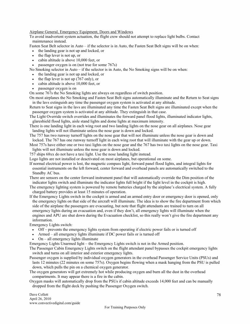
Dave Collett April 26, 2010 www.convectivedigital.com/guide
For Training Purposes Only
78
Airplane General, Emergency Equipment, Doors and Windows To avoid inadvertent system actuation, the flight crew should not attempt to replace light bulbs. Contact
maintenance instead. Fasten Seat Belt selector in Auto – if the selector is in Auto, the Fasten Seat Belt signs will be on when: the landing gear is not up and locked, or the flap lever is not up, or cabin altitude is above 10,000 feet, or passenger oxygen is on (not true for some 767s)
No Smoking selector in Auto – if the selector is in Auto, the No Smoking signs will be on when: the landing gear is not up and locked, or the flap lever is not up (767 only), or cabin altitude is above 10,000 feet, or passenger oxygen is on
On some 767s the No Smoking lights are always on regardless of switch position. On most airplanes the No Smoking and Fasten Seat Belt signs automatically illuminate and the Return to Seat signs
in the lavs extinguish any time the passenger oxygen system is activated at any altitude. Return to Seat signs in the lavs are illuminated any time the Fasten Seat Belt signs are illuminated except when the
passenger oxygen system is activated at any altitude. They extinguish in that case. The Light Override switch overrides and illuminates the forward panel flood lights, illuminated indicator lights,
glareshield flood lights, aisle stand lights and dome lights at maximum intensity. There is one landing light in each wing root and two landing lights on the nose gear on all airplanes. Nose gear
landing lights will not illuminate unless the nose gear is down and locked. The 757 has two runway turnoff lights on the nose gear that will not illuminate unless the nose gear is down and
locked. The 767 has one runway turnoff light in each wing root that will illuminate with the gear up or down. Most 757s have either one or two taxi lights on the nose gear and the 767 has two taxi lights on the nose gear. Taxi
lights will not illuminate unless the nose gear is down and locked. 757 ships 68xx do not have a taxi light. Use the nose landing light instead. Logo lights are not installed or deactivated on most airplanes, but operational on some. If normal electrical power is lost, the magnetic compass light, forward panel flood lights, and integral lights for
essential instruments on the left forward, center forward and overhead panels are automatically switched to the Standby AC bus.
There are sensors on the center forward instrument panel that will automatically override the Dim position of the indicator lights switch and illuminate the indicator lights full bright if the light level in the cockpit is high.
The emergency lighting system is powered by remote batteries charged by the airplane’s electrical system. A fully charged battery provides at least 15 minutes of operation.
If the Emergency Lights switch in the cockpit is armed and an armed entry door or emergency door is opened, only the emergency lights on that side of the aircraft will illuminate. The idea is to show the fire department from which side of the airplane the passengers are evacuating, but note that flight attendants are trained to turn on all emergency lights during an evacuation and, even if they don’t, all emergency lights will illuminate when the engines and APU are shut down during the Evacuation checklist, so this really won’t give the fire department any information.
Emergency Lights switch: Off – prevents the emergency lights system from operating if electric power fails or is turned off Armed – all emergency lights illuminate if DC power fails or is turned off On – all emergency lights illuminate
Emergency Lights Unarmed light – the Emergency Lights switch is not in the Armed position. The Passenger Cabin Emergency Lights switch on the flight attendant panel bypasses the cockpit emergency lights
switch and turns on all interior and exterior emergency lights. Passenger oxygen is supplied by individual oxygen generators in the overhead Passenger Service Units (PSUs) and
lasts 12 minutes (22 minutes on some 757s). Oxygen begins flowing when a mask hanging from the PSU is pulled down, which pulls the pin on a chemical oxygen generator.
The oxygen generators will get extremely hot while producing oxygen and burn all the dust in the overhead compartments. It may appear there is a fire in the cabin.
Oxygen masks will automatically drop from the PSUs if cabin altitude exceeds 14,000 feet and can be manually dropped from the flight deck by pushing the Passenger Oxygen switch.

Dave Collett April 26, 2010 www.convectivedigital.com/guide
For Training Purposes Only
79
The Passenger Oxygen On light indicates the signal has been sent to open the PSU doors. Do not activate the passenger oxygen system during a smoke or fumes situation. It mixes cabin air with oxygen and
therefore does not provide any protection for the passengers. It is also an extreme fire hazard. An Emergency Locator Transmitter (ELT) is located in the cockpit and should be taken by the F/O after ditching.
There is also a second ELT in the cabin. Flight deck windows can be opened from inside for emergency escape, but cannot be opened from outside the
airplane. No rescue from outside. Flight deck windows can also be opened and closed in flight at speeds below 250 knots (below clean speed
recommended) if the airplane is unpressurized. If the forward windows are damaged, forward visibility is possible by looking out an open side window.
The flight deck door will unlock when power is removed from the airplane. Decompression panels will open to equalize pressure in the event of a rapid decompression.
Entry doors have power assist to aid in opening the door and deploying the slide in the event of an emergency. Escape slides at the entry doors are also configured as life rafts. There is an additional life raft stored in a ceiling
compartment. Wing slides are not life rafts and may not be used as flotation devices. Emergency door slides on 757 ships 68xx are not life rafts, but may be used as auxiliary flotation devices. Escape slides have manual inflation handles in case the slide does not automatically inflate. On the 757, the slide rafts are too small to hold a survival kit, so a raft survival kit is stored in an overhead
compartment near each entry door. Don’t forget it. If armed, the escape slide automatically disarms if the door is opened from outside the airplane. Entry Doors – six on the 757 and either four or six on the 767. If an entry door is not closed, latched and locked, the
Entry Doors light on the overhead panel will illuminate and EICAS will show which door(s) are open. Emergency Doors – four overwing emergency doors on most 757s, two emergency doors aft of the wing on 757
ships 68xx, and either two or four overwing emergency doors on the 767. Emergency doors are armed at all times and opening an emergency door will automatically deploy the door slide or the wing slide. If an emergency door or a wing slide door is not closed, latched and locked, the Emer Doors light on the overhead panel will illuminate and EICAS will give the location. If more than one door is open, a single EICAS message will indicate multiple doors.
Cargo Doors – two cargo doors (forward and aft) on the 757 and three cargo doors (forward, aft and bulk) on the 767. If a cargo door is not closed, latched and locked, the Cargo Doors light on the overhead panel will illuminate and EICAS will give the location. If more than one door is open, a single EICAS message will indicate multiple doors.
Forward and aft cargo doors are normally operated electrically (Ground Handling bus), but may be operated manually if necessary. The bulk cargo door on the 767 is operated manually.
Access Doors – two access doors (forward equipment bay and electrical equipment (E/E) compartment) on all airplanes. If an access door is not closed, latched and locked, the Access Doors light on the overhead panel will illuminate and EICAS will give the location. If both doors are open, the EICAS message will be Access Doors.
Potable water is stored in a single tank behind the aft cargo compartment. There are two water service panels – one on the right forward fuselage just behind and below the 1R door and one at the rear of the aircraft on the bottom centerline under the aft service doors.
Each lav and each galley has a water shutoff valve and a drain valve for isolation purposes. Water from galley and lav sinks is drained overboard through two heated drain masts on the bottom of the airplane. Lavs on the 757 have individual, self-contained waste tanks and are serviced from three service panels; one on the
forward left side, one on the mid left side, just forward of the wing, and one on the rear left side near the aft potable water service panel.
The 767 uses a vacuum pump or cabin differential pressure to route lav waste to two storage tanks located in the bulk cargo compartment. All 767ERs and some 767–300s have two waste tank sensors in each tank. If a sensor indicates the tank is full, the Lav Inop light illuminates and the lavs on that tank are shut down. Pressing the Sensor Off switch allows the lavs to be used provided the tank is not completely full. A Sensor Foul light illuminates if a sensor becomes fouled or dirty and may shut down all lavs on that tank.
On some airplanes, the flight deck speakers are muted when any transmission is made with the boom mic or hand mic. Therefore, at least one pilot must have his headset on to monitor the radios if the boom mic or hand mic is used for PAs or interphone communication. The speaker does not mute if the handset on the aft pedestal is used or if the audio panel mic switch is in OXY.

Dave Collett April 26, 2010 www.convectivedigital.com/guide
For Training Purposes Only
80
Air Conditioning Two identical air conditioning packs cool bleed air from the engines, APU or high-pressure air from a ground source
(huffer cart). Bleed air is pre-cooled before entering a pack. The two packs are controlled by two identical pack controllers and pack output is automatically increased during
high pack demand times (failed opposite pack or failed recirc fan) and automatically reduced during times of high bleed air demand (failed engine).
With the pack selector in Off, the pack valve is closed and the Pack Off light is illuminated. With the pack selector in Auto, pack output temperature is determined by the compartment requiring the coolest air
and then warm trim air is added to the other compartments as determined by their individual zone temperature controllers to maintain the desired temperature in those compartments.
With the pack selector in the Standby mode (not in Auto), pack output temperature is determined by the position of the pack selector: N (normal) – pack output is a constant, moderate temperature C (cool) – pack output is full cold W (warm) – pack output is full warm
The Pack Inop light and a Pack Temp EICAS message will illuminate for all pack control system faults and overheats. If the problem was an automatic control system fault or a pack outlet temperature overheat, the pack will continue operating in an uncontrolled, degraded mode and flight crew action is necessary. If the problem was an internal pack overheat, the pack valve will close and the Pack Inop light will be accompanied by a Pack Off light and a Pack Off EICAS message. This is the classic pack trip and the pack may be reset with the pack reset switch after it has cooled to a temperature below the overheat level. Pack Inop light only – controller fault or outlet overheat Pack Inop and Pack Off lights – pack trip caused by an internal overheat
Air from the packs flows to a mix manifold where it is mixed with returning air from the recirc fans and distributed to the cabin, however the flight deck receives 100% fresh air from the left pack at a slightly higher pressure to keep smoke and fumes out of the flight deck. If the left pack is inop, the flight deck receives air from the mix manifold.
The terms “compartment” and “zone” are used interchangeably in the Boeing manuals for the temperature control compartments.
The 757 is divided into three compartments (flight deck, forward cabin, aft cabin) and the 767 is divided into four compartments (flight deck, forward cabin, mid cabin, aft cabin). Each compartment has a temperature controller to control the temperature in that compartment by adding warm trim air if necessary. The 757 temperature controllers have Auto and Off positions for all compartments and the 767 temperature controllers have Auto and Manual positions for the flight deck compartment and Auto and Off positions for the other zones. The manual position allows manual control of the flight deck trim air valve, if necessary, and there is a trim air valve position indicator next to the control.
Compartment Temperature Controls: Auto – automatic temperature control selectable between 65ºF and 85ºF (18ºC and 30ºC) Off – compartment trim air valve is closed (all compartments except 767 flight deck) Man – compartment trim air valve is controlled manually (767 flight deck compartment only)
The Compartment Temperature Inop light will illuminate to indicate: a fault in zone temperature controller the zone temperature controller switch is off (except a flight deck controller on the 767) the trim air switch is off (all compartment Inop lights would be on in this case)
If the trim air switch is off, the cabin temperature controller attempts to maintain all compartments at an average temperature.
Recirc fans allow the packs to be operated at a reduced flow by returning cabin air to the mix manifold. On the 757, the left recirc fan draws air through the forward E/E system and should not be turned off because that will cause the overboard exhaust valve to latch open requiring maintenance action to reset. Other recirc fans may be turned off to provide a more rapid exchange of air in the cabin.
The gasper system (if installed) draws air from the forward cabin overhead air conditioning ducts and discharges it from the gasper outlets on the passenger service units.
Shoulder heaters electrically warm the air in the cockpit side window diffusers. The High setting is only available in flight, but the Low setting is available in flight or on the ground.
Foot heaters electrically warm the cockpit floorboards (no air flow) and are only available in flight.

Dave Collett April 26, 2010 www.convectivedigital.com/guide
For Training Purposes Only
81
Equipment Cooling - 757 On the 757, the equipment cooling system supplies cooling air to the forward equipment racks and flight deck
avionics. The system has a supply fan (actually two fans; normal and alternate) that draws air from the cabin and forces it through the equipment racks and avionics and then the left recirc fan returns the air to the air conditioning mix manifold. If differential pressure in the system is low (left recirc fan not operating), the overboard exhaust valve latches open and most of the air is exhausted overboard. As previously mentioned, the left recirc fan should not be turned off because resetting the overboard exhaust valve requires maintenance action.
Overheat light – insufficient airflow for equipment cooling due to a failure of the supply fan or the overboard exhaust valve is not open with the left recirc fan off or failed. The Overheat light is accompanied by the Equipment Overheat EICAS message and a ground crew call horn if on the ground. If the Overheat light remains illuminated, avionics not on the Standby busses (e.g. EFIS flight instruments) are subject to imminent failure. Avionics on the Standby busses (e.g. standby flight instruments) are reliable for 90 minutes.
Alternate switch – turns on the alternate supply fan or opens the overboard exhaust valve as necessary. Smoke light – smoke is detected in the equipment cooling ducts and the system automatically attempts to remove it
by turning the recirc fan off, switching one or both packs to high flow and latching the overboard exhaust valve open. Smoke removal is completely automatic, however the source of the smoke should be investigated.
Equipment Cooling - 767 Just like the 757, the equipment cooling system supplies cooling air to the forward equipment racks and flight deck
avionics on the 767. System operation is automatic with the Equipment Cooling selector in Auto. On the ground, the system considers
engine and pack operation, skin temperature and outside temperature to determine the correct system configuration and a supply fan and an exhaust fan either recirculate cooling air or port it overboard as necessary. In flight, only the exhaust fan operates and cooling air is recirculated.
Equipment Cooling Selector: Auto – positions the cooling system for “automatic operation” and provides “best cooling for the conditions” Standby – positions the cooling system for “inboard air flow” and provides “maximum cooling” Override – positions the cooling system for “reverse air flow” and provides “differential pressure cooling”
No Cooling light – no reverse airflow through the E/E compartment avionics after selecting Override. The light is only active in Override. If the No Cooling light remains illuminated, avionics not on the Standby busses (e.g. EFIS flight instruments) are subject to imminent failure. Avionics on the Standby busses (e.g. standby flight instruments) are reliable for 90 minutes.
Valve light – equipment cooling valves are not in their commanded position. Overheat light – high temperature or low airflow in the equipment cooling system. Smoke light – smoke is detected in the forward equipment cooling ducts. In general, for Equipment Cooling Non-Normals on the 767, “point the switch at the light:” for Valve or Overheat lights – go to Standby for the Smoke light – go to Override
Cargo Heat Cargo heat on the 757 is completely automatic. On the 767, bleed air is used to heat the forward, aft and bulk cargo compartments. With the Cargo Heat switches
on, bleed air is ducted to each compartment through a shutoff valve and a heat control valve. The heat control valve modulates to maintain the temperature in the compartment within a “standard control range,” the lower limit of which is above approximately 45º F. (The actual range is not specified.) If the temperature exceeds the standard control range, such as would happen if the heat control valve failed open, the Overheat light illuminates. If the temperature continues to rise and exceeds approximately 90º F, the shutoff valve closes and bleed air is removed. When the temperature decreases back into the standard control range, the Overheat light extinguishes, the shutoff valve reopens and bleed air is reapplied. Cargo compartment temperature will then cycle between the standard control range and 90º F.
The Bulk Cargo Heat selector on the P-61 panel reprograms the Heat Control valve for the bulk cargo compartment to maintain above approximately 65ºF and turns on a vent fan to allow carrying animals.
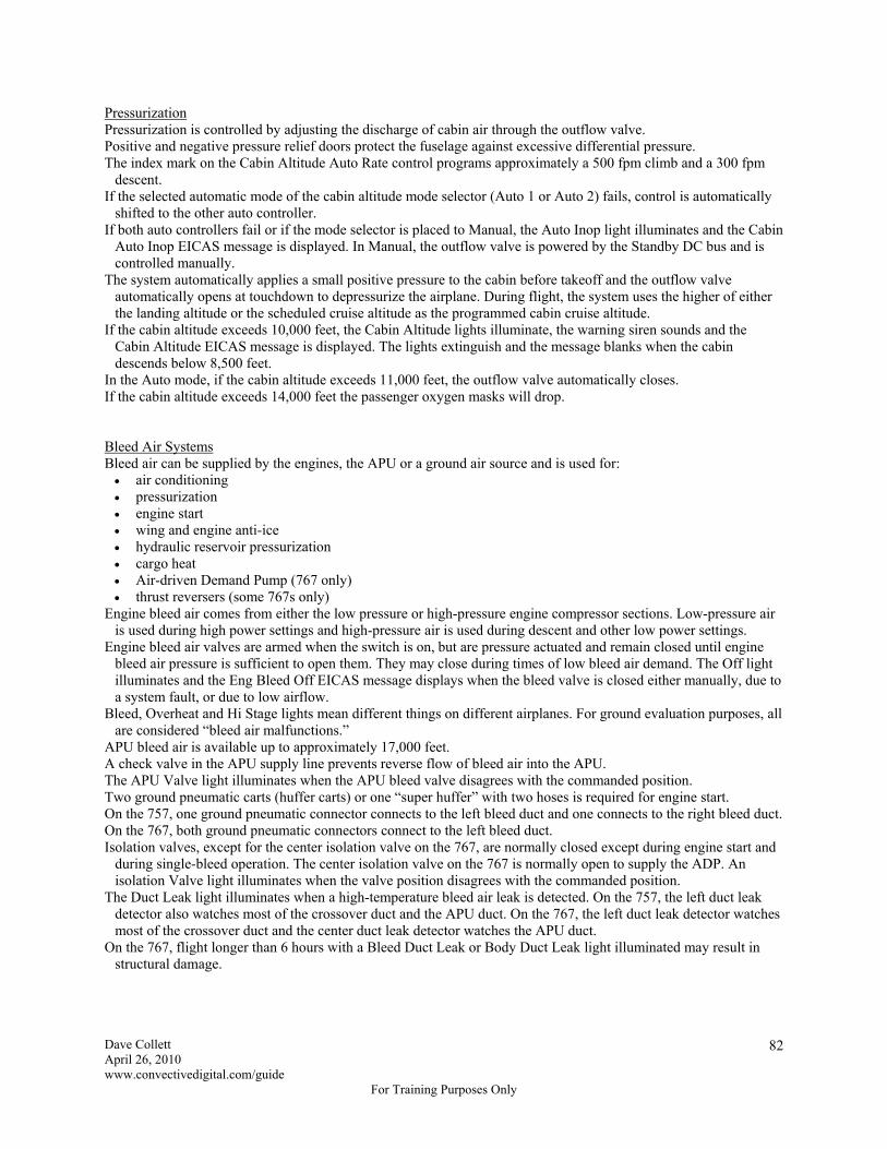
Dave Collett April 26, 2010 www.convectivedigital.com/guide
For Training Purposes Only
82
Pressurization Pressurization is controlled by adjusting the discharge of cabin air through the outflow valve. Positive and negative pressure relief doors protect the fuselage against excessive differential pressure. The index mark on the Cabin Altitude Auto Rate control programs approximately a 500 fpm climb and a 300 fpm
descent. If the selected automatic mode of the cabin altitude mode selector (Auto 1 or Auto 2) fails, control is automatically
shifted to the other auto controller. If both auto controllers fail or if the mode selector is placed to Manual, the Auto Inop light illuminates and the Cabin
Auto Inop EICAS message is displayed. In Manual, the outflow valve is powered by the Standby DC bus and is controlled manually.
The system automatically applies a small positive pressure to the cabin before takeoff and the outflow valve automatically opens at touchdown to depressurize the airplane. During flight, the system uses the higher of either the landing altitude or the scheduled cruise altitude as the programmed cabin cruise altitude.
If the cabin altitude exceeds 10,000 feet, the Cabin Altitude lights illuminate, the warning siren sounds and the Cabin Altitude EICAS message is displayed. The lights extinguish and the message blanks when the cabin descends below 8,500 feet.
In the Auto mode, if the cabin altitude exceeds 11,000 feet, the outflow valve automatically closes. If the cabin altitude exceeds 14,000 feet the passenger oxygen masks will drop. Bleed Air Systems Bleed air can be supplied by the engines, the APU or a ground air source and is used for: air conditioning pressurization engine start wing and engine anti-ice hydraulic reservoir pressurization cargo heat Air-driven Demand Pump (767 only) thrust reversers (some 767s only)
Engine bleed air comes from either the low pressure or high-pressure engine compressor sections. Low-pressure air is used during high power settings and high-pressure air is used during descent and other low power settings.
Engine bleed air valves are armed when the switch is on, but are pressure actuated and remain closed until engine bleed air pressure is sufficient to open them. They may close during times of low bleed air demand. The Off light illuminates and the Eng Bleed Off EICAS message displays when the bleed valve is closed either manually, due to a system fault, or due to low airflow.
Bleed, Overheat and Hi Stage lights mean different things on different airplanes. For ground evaluation purposes, all are considered “bleed air malfunctions.”
APU bleed air is available up to approximately 17,000 feet. A check valve in the APU supply line prevents reverse flow of bleed air into the APU. The APU Valve light illuminates when the APU bleed valve disagrees with the commanded position. Two ground pneumatic carts (huffer carts) or one “super huffer” with two hoses is required for engine start. On the 757, one ground pneumatic connector connects to the left bleed duct and one connects to the right bleed duct. On the 767, both ground pneumatic connectors connect to the left bleed duct. Isolation valves, except for the center isolation valve on the 767, are normally closed except during engine start and
during single-bleed operation. The center isolation valve on the 767 is normally open to supply the ADP. An isolation Valve light illuminates when the valve position disagrees with the commanded position.
The Duct Leak light illuminates when a high-temperature bleed air leak is detected. On the 757, the left duct leak detector also watches most of the crossover duct and the APU duct. On the 767, the left duct leak detector watches most of the crossover duct and the center duct leak detector watches the APU duct.
On the 767, flight longer than 6 hours with a Bleed Duct Leak or Body Duct Leak light illuminated may result in structural damage.
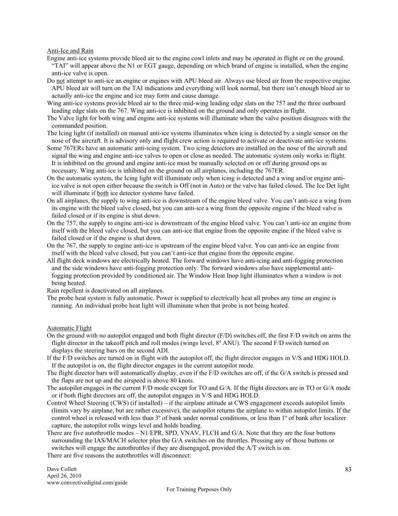
Dave Collett April 26, 2010 www.convectivedigital.com/guide
For Training Purposes Only
83
Anti-Ice and Rain Engine anti-ice systems provide bleed air to the engine cowl inlets and may be operated in flight or on the ground.
“TAI” will appear above the N1 or EGT gauge, depending on which brand of engine is installed, when the engine anti-ice valve is open.
Do not attempt to anti-ice an engine or engines with APU bleed air. Always use bleed air from the respective engine. APU bleed air will turn on the TAI indications and everything will look normal, but there isn’t enough bleed air to actually anti-ice the engine and ice may form and cause damage.
Wing anti-ice systems provide bleed air to the three mid-wing leading edge slats on the 757 and the three outboard leading edge slats on the 767. Wing anti-ice is inhibited on the ground and only operates in flight.
The Valve light for both wing and engine anti-ice systems will illuminate when the valve position disagrees with the commanded position.
The Icing light (if installed) on manual anti-ice systems illuminates when icing is detected by a single sensor on the nose of the aircraft. It is advisory only and flight crew action is required to activate or deactivate anti-ice systems.
Some 767ERs have an automatic anti-icing system. Two icing detectors are installed on the nose of the aircraft and signal the wing and engine anti-ice valves to open or close as needed. The automatic system only works in flight. It is inhibited on the ground and engine anti-ice must be manually selected on or off during ground ops as necessary. Wing anti-ice is inhibited on the ground on all airplanes, including the 767ER.
On the automatic system, the Icing light will illuminate only when icing is detected and a wing and/or engine anti-ice valve is not open either because the switch is Off (not in Auto) or the valve has failed closed. The Ice Det light will illuminate if both ice detector systems have failed.
On all airplanes, the supply to wing anti-ice is downstream of the engine bleed valve. You can’t anti-ice a wing from its engine with the bleed valve closed, but you can anti-ice a wing from the opposite engine if the bleed valve is failed closed or if its engine is shut down.
On the 757, the supply to engine anti-ice is downstream of the engine bleed valve. You can’t anti-ice an engine from itself with the bleed valve closed, but you can anti-ice that engine from the opposite engine if the bleed valve is failed closed or if the engine is shut down.
On the 767, the supply to engine anti-ice is upstream of the engine bleed valve. You can anti-ice an engine from itself with the bleed valve closed, but you can’t anti-ice that engine from the opposite engine.
All flight deck windows are electrically heated. The forward windows have anti-icing and anti-fogging protection and the side windows have anti-fogging protection only. The forward windows also have supplemental anti-fogging protection provided by conditioned air. The Window Heat Inop light illuminates when a window is not being heated.
Rain repellent is deactivated on all airplanes. The probe heat system is fully automatic. Power is supplied to electrically heat all probes any time an engine is
running. An individual probe heat light will illuminate when that probe is not being heated. Automatic Flight On the ground with no autopilot engaged and both flight director (F/D) switches off, the first F/D switch on arms the
flight director in the takeoff pitch and roll modes (wings level, 8º ANU). The second F/D switch turned on displays the steering bars on the second ADI.
If the F/D switches are turned on in flight with the autopilot off, the flight director engages in V/S and HDG HOLD. If the autopilot is on, the flight director engages in the current autopilot mode.
The flight director bars will automatically display, even if the F/D switches are off, if the G/A switch is pressed and the flaps are not up and the airspeed is above 80 knots.
The autopilot engages in the current F/D mode except for TO and G/A. If the flight directors are in TO or G/A mode or if both flight directors are off, the autopilot engages in V/S and HDG HOLD.
Control Wheel Steering (CWS) (if installed) – if the airplane attitude at CWS engagement exceeds autopilot limits (limits vary by airplane, but are rather excessive), the autopilot returns the airplane to within autopilot limits. If the control wheel is released with less than 3º of bank under normal conditions, or less than 1º of bank after localizer capture, the autopilot rolls wings level and holds heading.
There are five autothrottle modes – N1/EPR, SPD, VNAV, FLCH and G/A. Note that they are the four buttons surrounding the IAS/MACH selector plus the G/A switches on the throttles. Pressing any of those buttons or switches will engage the autothrottles if they are disengaged, provided the A/T switch is on.
There are five reasons the autothrottles will disconnect:

Dave Collett April 26, 2010 www.convectivedigital.com/guide
For Training Purposes Only
84
A/T Arm switch is turned off A/T Disconnect switch on a throttle is pushed a thrust reverser is deployed TMC failure loss of the primary engine parameter (EPR or N1) in an EEC
N1/EPR switch – the autothrottles drive to and hold the reference N1/EPR displayed on EICAS subject to maximum speed limits.
SPD Switch – the autothrottles maintain the speed or Mach displayed in the MCP window subject to maximum and minimum speed limits.
IAS/Mach changeover – IAS changes to Mach in climb at approximately .80 M, and Mach changes to IAS in descent at approximately 300 KIAS.
LNAV will engage if the airplane is within 2½ nm of the active route. Otherwise it just arms. LNAV will maintain the present heading when: passing the last waypoint prior to a route discontinuity passing the last active route waypoint passing the last offset route waypoint activating an inactive route or activating an airway intercept and not within LNAV capture criteria
On 767s, pressing VNAV changes the thrust reference from TO to CLB on takeoff if above 400' RA. On 757s, Climb mode must be manually selected on the Thrust Mode Select Panel.
Bank Limit Selector in Auto – the bank used in HDG SEL mode varies with airspeed from 15-25º. It has no effect on other roll modes.
Vertical Speed – in Vertical Speed mode, the airplane will fly away from a captured altitude and there is no high or low speed protection. Use with caution.
Heading Hold switch – the autopilot or flight director will roll wings level and then hold that heading. Altitude Hold switch – the autopilot or flight director will hold, or return to, the altitude at the time the switch was
pressed. LOC capture can occur when the intercept track angle is within 120º of the localizer course. G/S capture can occur when the intercept track angle is within 80º of the localizer course. Either LOC or G/S can be captured first. If neither LOC or G/S has been captured, press the APP switch again or select another pitch or roll mode to disarm
Approach mode. With only LOC or G/S captured, select another roll or pitch mode (as appropriate) to disarm Approach mode. After LOC and G/S capture, the only way to deselect Approach mode is to disengage the autopilot and cycle both
flight director switches or by selecting G/A mode. On a backcourse localizer approach, press the B/CRS switch before the LOC switch because, if LOC is armed first,
it’s possible for the autopilot or flight director to capture the front course in the instant before B/CRS is pushed and the airplane will proceed in the wrong direction. Push the buttons in alphabetical order or in the same order as you say the name of the approach, i.e. “Backcourse Localizer.”
A/P Disconnect light – an autopilot was automatically or manually disconnected. Auto Pilot light – if an autoflight failure affects only the active mode, the autopilot will remain engaged in an
attitude stabilizing mode, the discrete Auto Pilot light will illuminate and an amber line will be drawn through the degraded mode annunciation. If the fault is not common to all autopilots, a different autopilot may be operational.
A/T Disconnect light – the autothrottles were disconnected. Three independent Flight Control Computers (FCCs) control three independent sets of autopilot servos to the
ailerons and elevators. Autopilot rudder control is used only during multiple-autopilot ILS approaches. Nosewheel steering is used by the autopilot during landing rollout after an autoland. Autopilot engagement requires at least two FCCs. Since the left and center FCCs are powered by the left AC bus, all
autopilots will be inop with a left AC bus failure. The left and center autopilots will work if the right AC bus is inop.
During an ILS approach with all three autopilots engaged, separate electrical power sources power the three FCCs and autopilots. The left autopilot is on the left main system, the center autopilot is on the Hot Battery bus and Standby AC bus through the standby inverter (the battery/standby system), and the right autopilot is on the right main system. See the Electrical section for more information.
Changes to autoland status below 200' RA are inhibited except for a transition to NO AUTOLAND.
Dave Collett April 26, 2010 www.convectivedigital.com/guide
For Training Purposes Only
85
On takeoff, the flight director commands V2 + 15 knots or liftoff speed + 15 knots, whichever is greater. If the current speed remains above the target speed for 5 seconds, the target speed resets to the current speed up to a maximum of V2 + 25 knots.
Go-Around arms in flight whenever the flaps are extended (Flaps 1 or greater) or at glideslope capture. Pressing a G/A switch engages the autothrottles to provide a climb of at least 2,000 fpm, causes the autopilot and/or flight director to command a climb at current airspeed or MCP airspeed, whichever is higher, and maintain the ground track at time of engagement. If the airspeed increases above the initial target speed and remains there for 5 seconds, the target speed resets to the current airspeed up to a maximum of MCP speed plus 25 knots. If the initial go-around speed was above MCP speed plus 25 knots, that speed is maintained.
Elevator authority is limited during single autopilot operation and may not be sufficient to counteract pitch up or pitch down during go-around or level off under certain conditions. Always be prepared to disconnect the autopilot and fly manually if necessary.
Altitude capture from a climb that requires a significant airspeed increase or thrust reduction may result in the autopilot descending away from the selected altitude in an attempt to increase airspeed. Once again, always be prepared to disconnect the autopilot and fly manually if necessary.
If LAND 2 is displayed on the ASA, the autopilot will automatically apply nose-up pitch trim as the airplane descends below 330' RA for 757s and below 100' RA for 767s. If the autopilot is then disengaged, it will take 20-30 pounds of forward pressure to counter the added pitch trim. If an automatic go-around is accomplished, the added trim is automatically removed.
During an autoland, G/A is inhibited after 2 seconds at or below 5' RA. If a G/A switch is pushed after that time, the flight director will command go-around pitch, but the autothrottles will not automatically advance.
During a multiple-autopilot approach and missed approach, the autopilots control the rudder. If on single engine, be prepared to manually apply rudder at the first change of either pitch or roll mode or if the autopilots are disengaged because the rudder will quickly move to its trimmed position and the airplane will roll abruptly.
Communications Nav Filter Selector – filters VOR, ADF and ILS audio: Voice – only voice transmissions can be heard Both – both voice and station identifiers can be heard Range – only station identifiers can be heard
Flight Interphone switch on the overhead panel (if installed) – connects the flight and cabin interphone systems together.
Service Interphone switch on the P-61 panel – On will add additional external (unpressurized area) headphone jacks to the cabin interphone system. The jack on the APU ground control panel on the nosewheel strut is part of the flight interphone system, however, and will work with the Service Interphone switch off.
Alert Call switch – calls all flight attendant stations. Cockpit Voice Recorder – all inputs are recorded continuously any time electrical power is applied to the airplane. Cockpit Voice Recorder test – during test, the needle displaces to the green band if all four channels are operating.
To erase, hold the erase switch for 2 seconds while on the ground with AC power applied and the parking brake set.
Flight Recorder – with the switch on the P-61 panel in Normal, the Flight Recorder is on any time an engine is running or any time in flight with electrical power available. The On position of the switch will manually turn it on and the Test position is for maintenance use only.
HF radios (if installed) use a common antenna. When one radio is transmitting, the antenna is disconnected from the other radio and it cannot be used to transmit or receive. Both radios can receive simultaneously, however, if neither is transmitting.
Decreasing HF sensitivity too far prevents reception, including SELCAL reception. Cabin PA priorities: flight deck announcements cabin announcements made from a flight attendant station pre-recorded announcements boarding music
Dave Collett April 26, 2010 www.convectivedigital.com/guide
For Training Purposes Only
86
Electrical APU and Engine Generator Control switches arm the generator breakers to close automatically when generator
power is available. Turning the switch off opens the generator breaker and resets fault trip circuitry. The switches are normally left on.
APU Generator Off light – the APU generator breaker is open due to a fault with the APU running or the switch is selected off. The light is normally off when the APU is off.
Engine Generator Off light – the engine generator breaker is open due to a fault or the engine is shut down. The light is normally on when the engine is shut down.
Bus Tie Switches in Auto: arm the automatic AC bus tie circuits arm the automatic DC bus tie circuits arm the automatic Flight Instrument Transfer bus circuits
Bus Tie Switches Off commands the AC bus tie, the DC bus tie and the Flight Instrument Transfer bus tie to open and resets fault trip circuitry.
AC Bus Isolation light – the bus tie switch is off or a fault has occurred automatically opening the bus tie breakers and isolating the busses.
AC Bus Off light – the left or right main AC bus is unpowered. External Power Avail light – external power is plugged in and power quality is acceptable. External Power On light – external power is powering a bus or busses. The external power switch manually applies or removes external power from the electrical system. It has priority
and will trip off any existing power source. Utility Bus switches connect or disconnect the Utility busses and Galley busses from the main AC busses and reset
overload and load shed circuitry. Utility Bus Off lights – the Utility busses and Galley busses are unpowered. Generator Drive lights – high oil temperature or low oil pressure in the Integrated Drive Generator (IDG). Generator Drive Disconnect switches disconnect the IDG from the engine. IDGs can only be reconnected on the
ground. Battery Switch On – allows the main battery to power the Battery bus and the Standby AC and DC busses if main
AC power is lost. Also allows the APU to be started. Battery Switch Off light – the battery switch is off. Battery Discharge light – the main battery is discharging. If the main battery is the only source of electrical power, it should power the standby system for approximately 30
minutes. On the 767, when the battery is depleted after 30 minutes, the gear and flaps cannot be lowered. Standby Power Selector: Off – Standby AC and DC busses are unpowered Auto – Standby AC and DC busses automatically transfer to battery power if normal AC power is lost Bat – Standby AC and DC busses manually connected to the main battery even if normal power is available
Standby Power Bus Off light – the Standby AC and/or Standby DC bus is unpowered. The entire airplane electrical load can be powered by any two main airplane AC power sources (left and right IDGs
and the APU generator) or by external power. Power sources operate isolated from each other. An Integrated Drive Generator (IDG) incorporates a generator and a constant speed drive in a single casing. The right IDG normally powers the Right AC bus and the left IDG normally powers the left AC bus. The APU generator is electrically identical to the IDG generators and can power either or both main AC busses and
may be used in flight as a replacement for a failed IDG. The priority for powering main AC busses is the respective IDG, APU generator and then the opposite IDG. If the APU is started with the APU Generator Control Switch on, the APU will automatically power both main AC
busses only if they are unpowered. The APU will not automatically disconnect other power sources. For example, if external power is powering the main AC busses and APU power becomes available, external power will continue powering the busses until deselected.
If starting an engine with external power connected, the engine generator will automatically take over its busses, leaving the opposite busses on external power. If the second engine is started while on external power, its generator will automatically take over its busses and the external power On light will extinguish. The Avail light will be on until external power is removed. There is no load shedding during engine start from external power.
Dave Collett April 26, 2010 www.convectivedigital.com/guide
For Training Purposes Only
87
If starting an engine with APU power, the engine will automatically take over its busses, leaving the opposite busses on the APU. Both Utility busses will shed during start of the first engine and re-power once the engine is supplying power. During start of the second engine, only the Utility bus on that side will shed and automatically re-power once the engine is supplying power. That engine will also automatically power its busses after engine start and the APU will be disconnected, however the APU generator Off light will not illuminate and the APU will continue running.
The main purpose of the bus tie system is to make sure the AC and DC busses are powered by any available source. Ground school functions of the bus tie system (PPI+3): prevents paralleling powers AC busses isolates faults allows the DC bus tie breaker to close with the loss of DC power allows the Captain’s flight instruments to remain powered with loss of the left AC bus allows the First Officer’s flight instruments to remain powered with loss of the right AC bus
A fault will illuminate the bus tie Isolation light and lock the bus tie breaker open, unpowering the bus. The bus tie breaker will not close until the fault is corrected.
Flight Instrument Transfer busses – the Captain’s flight instruments are powered by the Captain’s Flight Instrument Transfer bus, which is normally powered by the left AC bus. The First Officer’s flight instruments are powered by the F/O’s Flight Instrument Transfer bus, which is normally powered by the right AC bus. If the Bus Tie switches are in Auto and a main AC bus becomes unpowered, the affected Flight Instrument Transfer bus automatically switches to the other main AC bus and remains powered.
Utility busses – left and right Utility busses are powered by their respective main AC busses. Galley busses are powered by their respective Utility busses. Ground Handling Bus – provides power for cargo doors, cargo handling and fuel servicing. It can only be powered
on the ground by either the APU or external power and will be powered whenever the APU is running or when the external power Avail light is illuminated. The APU or external power does not have to be selected. If starting at the gate with an inop APU, late bags cannot be added after pushback because neither the APU or external power is available.
Ground Service bus – normally powered by the right AC bus whenever the right electrical system is powered. If the right electrical system is not powered, the ground service switch on the forward flight attendant panel will switch the Ground Service bus to the Ground Handling bus and allow the APU or external power to power it on the ground. The Ground Service bus powers the main battery charger, the APU battery charger and misc. cabin and system loads. (BELL: battery chargers, equipment cooling fan, left forward boost pump, lights.)
Autopilot power sources: the left and center autopilots are normally powered by the left main system and the right autopilot is normally
powered by the right main system when Approach mode is selected at any altitude, the autopilot power sources separate (Bus Separation). The
left main system powers the left autopilot and the Captain’s Flight Instrument Transfer bus. The right main system powers the right autopilot and the First Officer’s Flight Instrument Transfer bus, and the battery/standby system (Hot Battery bus and Standby AC bus through the standby inverter) powers the center autopilot.
if a single generator fails prior to 200' RA on the approach, the bus tie breakers close to power the unpowered AC and DC busses, the center autopilot switches back to the left main system and NO LAND 3 appears on the Autoland Status Annunciator (ASA)
below 200' RA on the approach, the bus tie breakers will not close if a generator is lost (Bus Isolation). The left or right AC bus and the associated left or right autopilot will remain unpowered, the flight instruments will remain powered through the Flight Instrument Transfer bus system, and the autoland will continue using only two autopilots. The ASA is inhibited from changing to NO LAND 3 below 200' RA, but it can change to NO AUTOLAND if additional failures occur.
if the APU is running, it can power an unpowered left or right AC bus in the event of a generator failure Bus Separation and Bus Isolation only occur on ILS approaches after Approach mode is selected when the autopilots are disengaged or when another pitch or roll mode is selected after an autopilot go-around
is performed, the electrical system reverts to normal, non-isolated operation Note: the Boeing books don’t mention them, but Delta drawings show a center AC bus and a center DC bus, which
power the center autopilot and center FCC. The center AC bus is normally powered by the left AC bus and the
Dave Collett April 26, 2010 www.convectivedigital.com/guide
For Training Purposes Only
88
center DC bus is normally powered by the left DC bus through the Battery bus. When Approach mode is selected, the center AC bus switches to the standby inverter through the Standby AC bus, the center DC bus switches to the Hot Battery bus, and the Battery bus also switches to the Hot Battery bus, thus causing bus separation. Even after bus separation, however, the center AC and DC busses are actually powered by the right main system through the battery charger and are backed up by the battery. (The drawings are available on DeltaNet as Ground School Handouts on the B757 and B767 Fleet page and are nice to have as you review this section.)
Bus Separation – if you’re “separated,” you might get back together. Bus Isolation – if you’re “isolated,” you’re not getting back together and your wife gets the house. If the left AC bus faults below 200' RA on a multiple autopilot approach, bus isolation will keep the center and right
autopilots engaged. If a go-around is made and another roll mode is selected at 400' RA, the system will revert back to non-isolated operation and all autopilots will disengage. It might be wise to delay selecting another roll mode in this case.
If the left AC bus faults above 200' RA, even if on a multiple autopilot approach, all autopilots disengage and the airplane must be hand flown.
Electrical load shedding occurs automatically to ensure power is available to critical and essential equipment. Load shedding priority – Galley busses first, then Utility busses. Utility busses are followed by individual equipment
items powered by the main AC busses. When additional power becomes available, systems are restored in the opposite order.
Load shedding examples: C2 electric hydraulic pump prior to engine start center tank fuel pumps prior to engine start Utility bus(ses) during engine start Utility busses after a generator failure center tank fuel pump after an engine failure cabin ceiling lights after an engine failure
Utility bus load shedding (BOSS): B – both thrust levers advanced to the takeoff range on the ground when on a single power source O – overload (electrical loads exceed the power available) S – starting engines with the APU providing electrical power S – single generator in flight
DC busses are powered by Transformer-Rectifier Units (TRUs) which are powered by their respective main AC bus. If a TRU fails, its DC bus is powered by the opposite DC bus through the DC bus tie if the Bus Tie switches are in
Auto. There are no flight deck controls for the main DC system. The left DC bus powers the Battery bus, which powers the Standby DC bus, provided the Standby Power switch is
in Auto. With the Battery switch on and the Standby Power switch in Auto, the main aircraft battery can act as a backup
source of power for the Hot Battery bus, Battery bus, Standby DC bus, and Standby AC bus through the standby inverter for approximately 30 minutes after the loss of all generators. Flight beyond 30 minutes in this situation will result in complete electrical failure. (On some aircraft the battery should never be the only source of electric power due to the Hydraulic Driven Generator.)
On a 767, complete electrical failure will result in the inability to extend the gear and flaps. The ADP requires DC power to operate and when the battery is depleted, the ADP air supply valve will close and the center hydraulic system will depressurize. Gear and flaps will not extend by either the normal or alternate method if this happens. (Center system hydraulics will not be available for normal gear and flap extension and electric power will not be available for alternate gear extension.)
If the airplane is on Standby power, all the CRT screens will be blank. (“Nobody can watch TV.”) If any ADI or HSI is powered (“If anybody can watch TV”), the airplane is not on Standby power.
IRS power sources – normally the IRUs operate on AC power from the left and right electrical systems and the main aircraft battery is an alternate power source. The ON DC light illuminates if the AC power source is lost and DC power is being used. The DC FAIL light illuminates if the DC power source is lost and normal AC power is being used. Both lights will be extinguished if both AC and DC power are either available or not available.
Aircraft without an HDG – on Standby power, the left and center IRUs will shut down after 5 minutes to save battery power and the right IRU will operate until the battery is depleted. (The right IRU is needed to provide heading information to the Captain’s RDMI card, which is available on Standby power.)
Dave Collett April 26, 2010 www.convectivedigital.com/guide
For Training Purposes Only
89
Aircraft with an HDG – on Standby power, the right IRU will shut down after 5 minutes to save battery power and the left and center IRUs will continue operating until battery depletion. If the HDG is operative, however, the aircraft will not be on Standby power and the left IRU will be powered by the Left AC Transfer Bus and the center IRU will be powered by the Hot Battery Bus. (Refer to the Differences section in Volume 1.)
With the aircraft powered normally, turning the Standby Power switch off will only unpower the Standby AC and DC busses.
The Battery position on the Standby Power switch insures the battery can power the Standby busses in case the automatic feature fails. It also disconnects the battery charger from the battery system, so the Standby busses will be powered by the battery even if normal power is available. In this case, the Standby busses will be unpowered when the battery is depleted after 30 minutes even though generator power may be available.
The battery/standby system consists of: the Hot Battery bus the Battery bus (4 busses) the Standby AC bus the Standby DC bus
Hot Battery bus – powers items that must be continuously powered, such as the clock, and is powered by the main battery prior to establishing electrical power. After establishing electrical power, the Hot Battery bus is powered by the main battery charger which is powered by the Ground Service bus, which is powered by either the right AC bus or the Ground Handling bus.
Battery bus – powered by the main battery through the Hot Battery bus prior to establishing electrical power if the Battery Switch is on. After establishing electrical power, the left DC bus powers the Battery bus and the main battery provides a backup source of power through the Hot Battery bus.
Standby AC bus – normally powered by the left AC bus, but can be powered by the main battery through the Hot Battery bus, Battery bus and standby inverter. If the Standby Power Selector is in BAT, the main battery powers the Standby AC bus through the standby inverter and the battery charger is removed from the circuit.
Standby DC bus – normally powered by the left DC bus through the Battery bus, but can be powered by the main battery through the Hot Battery bus and Battery bus. If the Standby Power Selector is in BAT, the main battery powers the Standby DC bus and the battery charger is removed from the circuit.
Items available on Standby Power until battery depletion (approximately 30 minutes): adequate lighting all IRUs for 5 minutes either the right IRU or the left and center IRUs
after 5 minutes fuel quantity indications manual pressurization controls and indicators left VOR (no DME) Master Warning and Caution standby flight instruments standby engine instruments engine oil pressure lights
center ILS Captain’s marker beacon lights Captain’s RDMI card and number 1 needle gear handle and half the green lights flap operation but no indication alternate stab trim manual speedbrakes fire detection and protection left VHF comm PA interphone
767ER Differences The 767ER and a few domestic 767s have a Hydraulic Driven Generator (HDG) as an additional source of electric
power. If both main AC busses are lost, after a 10-15 second delay, the HDG will automatically power the busses necessary for ETOPS operation, including either the Captain’s or F/O’s EFIS, without a time limit. The Air-driven Demand Pump (ADP) will turn on any time the HDG is operating because the center electric hydraulic pumps will be unpowered. The HDG will automatically shut down if power from an engine generator or the APU is restored. If the HDG fails, the aircraft main battery will power the Hot Battery bus, the Battery bus and Standby AC and Standby DC busses for 30 minutes. Only standby flight instruments and other items powered by Standby Power will be available in that case.

Dave Collett April 26, 2010 www.convectivedigital.com/guide
For Training Purposes Only
90
The HDG is powered by the center hydraulic system and starts automatically if both left and right AC busses are unpowered. The HDG provides power to: the Hot Battery bus the Battery bus the Standby AC bus (7 busses) the Standby DC bus the left AC Transfer bus the right AC Transfer bus either the Captain’s or First Officer’s Flight Instrument Transfer bus
The HDG provides less DC power than the main battery so when the HDG first starts operating the Battery Discharge light may illuminate until the battery drains to the power level produced by the HDG.
AC Transfer Busses – left and right AC Transfer busses power items necessary for ETOPS that are not powered by the battery/standby system. They are normally powered by the left and right AC busses but will be powered by the hydraulic driven generator if both AC busses are unpowered. They do not transfer to the opposite main bus like the Flight Instrument Transfer busses, but only to the HDG if both main AC busses are unpowered.
Flight Instrument Transfer Busses – if power is lost to both main AC busses, either the Captain’s or the First Officer’s flight instruments are powered by the HDG depending on the position of the Flight Instrument Bus Power switch. If the switch is off, the Captain’s instruments will be powered. If the switch is placed to the ALTN position, the First Officer’s flight instruments will be powered after a 10-15 second loss of all electronic flight instruments.
If on HDG power, the EFIS screens may blank on a go-around as the gear is retracted. 757 Differences 757 aircraft certified for ETOPS also have an HDG as an additional source of electrical power. It is powered by the
left hydraulic system and activates automatically when both left and right main AC busses are unpowered. The HDG on the 757 supplies power to the same seven busses as the HDG on the 767ER, with one exception. There
is no Flight Instrument Bus Power switch on the 757. If the HDG is operating, it will provide power to the Captain’s Flight Instrument Transfer bus with no option to power the First Officer’s instruments.
The 757 HDG also provides less DC power than the main battery so when the HDG first starts operating the Battery Discharge light may illuminate until the battery drains to the power level produced by the HDG.

Dave Collett April 26, 2010 www.convectivedigital.com/guide
For Training Purposes Only
91
Electrical System Summary Bus or Component Normal Power Source Backup Power Source(s)
Left AC bus Left IDG APU or right AC bus through the bus tie
Right AC bus Right IDG APU or left AC bus through the bus tie
Capt Flt Inst Transfer bus Left AC bus Right AC bus or HDG if both busses unpowered*
F/O Flt Inst Transfer bus Right AC bus Left AC bus or HDG if both busses unpowered*
Ground Service bus Right AC bus Ground Handling bus through switch on F/A panel
Ground Handling bus External power or APU None, only powered on the ground
Left Utility bus Left AC bus None
Right Utility bus Right AC bus None
Left Galley bus Left Utility bus None
Right Galley bus Right Utility bus None
Left TRU Left AC bus None
Right TRU Right AC bus None
Left DC bus Left TRU Right DC bus through the bus tie
Right DC bus Right TRU Left DC bus through the bus tie
Main Battery Charger Ground Service bus None
APU Battery Charger Ground Service bus None
Hot Battery bus Main Battery Charger Main Battery or HDG**
Battery bus Left DC bus Main Battery through the Hot Battery bus or HDG**
Standby AC bus Left AC bus Main Battery through Standby Inverter or HDG**
Standby DC bus Battery bus Main Battery or HDG**
HDG Aircraft Only
Left AC Transfer bus Left AC bus HDG only if both AC busses unpowered
Right AC Transfer bus Right AC bus HDG only if both AC busses unpowered * Either the Captain’s or First Officer’s Flight Instrument Transfer bus on 767 aircraft with an HDG installed. On
the 757 with an HDG installed, only the Captain’s Flight Instrument Transfer bus can be powered from the HDG. ** If installed. Engines The 757 is powered by two Pratt & Whitney PW2037 engines rated at 37,000 pounds of takeoff thrust each. Domestic 767s are powered by two General Electric CF6-80A2 engines rated at 49,200 pounds of takeoff thrust
each. 767ERs are powered either by two General Electric CF6-80C2 engines or by two Pratt & Whitney PW4060 engines,
all of which are rated at 60,200 pounds of takeoff thrust each. The N1 and N2 rotors are mechanically independent. The N2 rotor drives the accessory gearbox. EPR, N1 and EGT are the primary engine indications for Pratt & Whitney engines and N1 and EGT are the primary
engine indications for General Electric engines. Primary engine indications are always displayed on the upper EICAS display.
Secondary engine indications (N2, fuel flow, oil pressure, oil temperature, oil quantity and vibration) are automatically displayed on the lower EICAS display when: displays initially receive electrical power a secondary engine parameter is exceeded
TAI will be displayed above the N1 indicator (P&W) or EGT indicator (GE) when engine anti-ice is on. On the 757, if only a single source of engine bleed air is available, a TAI bug will be displayed on the appropriate
N1 gauge showing the minimum N1 required for anti-ice operation. Normal operating ranges are displayed on engine instruments in white.
Dave Collett April 26, 2010 www.convectivedigital.com/guide
For Training Purposes Only
92
Oil pressure and oil temperature have caution ranges indicated by amber bands. If the caution range is reached, the readout, readout box and pointer all change to amber.
EGT has a max continuous limit indicated by an amber band. If EGT reaches the max continuous limit, the readout, readout box, pointer and dial all change to amber, however the EGT indication is inhibited from changing to amber for five minutes during takeoff or go-around. On some engines, the inhibit is extended to 10 minutes after an engine failure.
N1, EGT, N2, oil pressure and oil temperature have operating limits indicated by red lines. If an operating limit is reached, the readout, readout box and pointer all change to red.
Maximum EPR or maximum N1is the maximum certified thrust limit for all phases of flight and varies with ambient conditions. It is calculated by the Electronic Engine Controller (EEC) or Thrust Management Computer (TMC). If the EEC is operating normally, the thrust levers can be moved to the forward stop and max EPR or max N1 will not be exceeded.
Maximum EPR/N1 is indicated by an amber line on the EPR/N1 dial and indications do not change color when the maximum is reached.
The “crow’s foot” is the reference or target EPR/N1. If it’s green, it’s a reference EPR/N1 calculated by the Thrust Management Computer. If it’s magenta, it’s a target EPR/N1 calculated by the FMC.
The command sector is a white band that shows the difference between commanded thrust and actual thrust during throttle movement.
REV is displayed above the EPR/N1 gauge when the reverser is activated. It will be amber when the reverser is in transit and green when the reverser is fully deployed.
The Thrust Management Computer calculates the reference EPR/N1 for takeoff, climb, cruise, continuous and go-around thrust. These modes can be selected on the Thrust Mode Select Panel (TMSP).
Assumed temperature for a reduced power takeoff may be set on the TMSP or in the FMS. Reference EPR/N1 can be manually set for one or both engines using the knob on the engine indication control
panel, however the autothrottles will not respond to a manually set EPR/N1. Electronic Engine Controller (EEC) Summary: all EECs are powered by a dedicated permanent magnet alternator (PMA) which is independent of airplane
power all EECs are Full Authority Digital Electronic Control (FADEC) except on the domestic 767 (GE engines with
the On-Inop switch). The thrust system on these airplanes is a hydromechanical engine fuel control with an EEC unit that provides trim inputs to drive the engine to an EEC-computed thrust level
EPR is the primary mode for P&W engines and N1 is the primary mode for GE engines autothrottles need the primary mode. If it’s lost, the autothrottles won’t work. on the 757, the EEC switch is a power switch. It allows maintenance to power the EEC with ship’s power. on the domestic 767 (GE engines), the EEC switch is an On-Off switch on the 767ER (P&W and GE), the EEC switch is a mode switch. It allows switching to the Alternate mode no EECs will prevent EGT overtemps all EECs will prevent N1 overspeeds P&W EECs will prevent EPR overboosts EECs will not prevent N2 overspeeds (schoolhouse answer) EECs on 767ER aircraft have Supplemental Control Units (SCU) to automatically transfer EEC power to the
Hot Battery bus if the PMA fails On the 757, if N2 overspeeds to 105%, the engine will roll back to 87% N2 and be uncontrollable. The throttle will
not control the engine and the engine will remain at 87% N2 until shut down. It must be shut down and restarted to clear the fault. That would be exciting on takeoff and, according to a ground school instructor, every time it’s happened the airplane ran off the runway.
On the 767 P&W, if N2 overspeeds, the engine rolls back to idle. On the 757, the fuel control selects minimum ground idle, minimum flight idle and approach idle, as necessary. On the 767, there are only two idle speeds and the EEC selects either minimum idle or approach idle as necessary.
On some airplanes, rotating the engine start selectors to CONT will manually select approach idle. Standby Engine Indicator (SEI) – in Auto, the display will be blank with AC power on the airplane and EICAS
operative.

Dave Collett April 26, 2010 www.convectivedigital.com/guide
For Training Purposes Only
93
Standby engine indications will be displayed when: AC power is lost (i.e. on Standby power) EICAS has failed either CRT has failed and Status is selected on the ground
On all airplanes, the start valves are downstream of the engine bleed valves. You can start an engine with its bleed valve closed, which is what we normally do.
A max start limit (red radial) is displayed on the EGT indicator when the fuel control is in Cutoff and remains displayed during start until the engine stabilizes in idle. The EGT indication changes to red if the EGT start limit is reached during starting.
During start, the Engine Start Selectors control the start valve and the Fuel Control Switches control ignition and fuel flow.
Minimum N2 for selecting Run during start is displayed as a magenta Fuel On command bug on the N2 indicator, even though normal fuel-on N2 is 25%.
Max motoring speed is when engine acceleration is less than 1% in 5 seconds. Fuel Control Switch in Run – opens engine and spar fuel valves and activates selected ignitors if armed. Engine Start Valve light – the start valve is not in the commanded position or the valve is open with N2 above 50%. Ignitor Selector: 757s and some 767s – selects one ignitor (1 or 2) or both ignitors in each engine to operate when directed by
the Engine Start Selector some 767s – selects one ignitor (Single) or both ignitors in each engine to operate when directed by the Engine
Start Selector. In Single, the ignitor automatically alternates with each engine start. on all airplanes, both ignitors operate when the Engine Start Selector is in FLT regardless of this switch
position Engine Start Selector: GND – opens the start valve and arms the selected ignitor(s), magnetically held until 50% N2 AUTO – released to AUTO at 50% N2 on start, closes the start valve and terminates ignition. Selected ignitors
(one or both) operate when flaps are extended (Flaps 1 or greater) or when the engine anti-ice is on. OFF – no ignition CONT – selected ignitors (one or both) operate continuously. No time limit. FLT – both ignitors operate continuously regardless of Ignition Selector position. No time limit.
Starter Duty Cycle: continuous for 5 minutes cool 30 seconds for each minute of operation after two consecutive 5-minute cycles, cool for 10 minutes before each additional 5-minute cycle
757 Stable start – 1, 2, 3, 6, 1 on the engine instruments for EPR, N1, EGT, N2 and fuel flow respectively. Starter Re-Engagement: recommended starter re-engagement speed (moving Engine Start Selector to GND) is 0% N2 normal starter re-engagement speed is 0-20% N2 engaging the starter with N2 above 20% is not recommended except in case of fire engaging the starter with N2 above 30% may result in starter or gearbox damage
The Inflight Start Envelope is displayed inflight when the fire handle is in, the fuel control switch is in cutoff, N2 is below idle, and both Primary and Secondary EICAS are displayed. If the current airspeed is too low for a windmilling start, X-BLD is displayed above the N2 counter and the Fuel On command bug is displayed on the N2 gauge.
Auto Relight – some 767s with GE engines have an auto relight feature. In flight or on the ground, if N2 drops below idle speed, the EEC will energize both ignitors in the engine.
Each engine has two ignitors. Dual ignitors are always used for inflight starts. Main AC is the normal power source for the ignitors and Standby AC is the backup source. Engine and Spar fuel valves are controlled by the fuel control switch and the fire handle. Eng Valve and Spar Valve lights illuminate momentarily as the valves open or close. Constant illumination indicates
the valve does not agree with the commanded position. Fuel filters and oil filters will bypass if they become clogged. 767s and some 757s display an EICAS message if a fuel filter is clogged, but on some 757s, the only indication of a
clogged fuel filter is a Status message (or engine flameout). Oil heats the fuel and fuel cools the oil in the fuel/oil heat exchanger. Automatic full-time fuel heat.

Dave Collett April 26, 2010 www.convectivedigital.com/guide
For Training Purposes Only
94
There are two independent oil pressure sensors. One supplies information to the oil pressure gauge and the other supplies information to the discrete oil pressure light on the forward panel and for the EICAS low oil pressure message. Actual low oil pressure would show on all three.
The white band at the bottom of the oil quantity indication is for crew awareness only. There is no minimum oil quantity inflight, so there are no flight crew procedures based solely on low oil quantity.
Thrust Reversers are hydraulically operated on the 757 and some 767s, and pneumatically operated on some 767s. They are available only on the ground. An interlock prevents inadvertent actuation and electromechanical locks protect in the event of additional system failures.
767s have an auto restow feature to apply hydraulic or pneumatic pressure if an uncommanded thrust reverser unlock is sensed.
When the reverse thrust levers are pulled aft to the interlock position, the autothrottles disengage, if engaged, and the speedbrakes deploy if not already deployed.
On the 767, the REV ISLN light above the fuel control switches indicates a fault is detected in the thrust reverser system. It will be accompanied by a REV ISLN VAL EICAS message. Additional system failures may cause inflight deployment, however the light and the associated EICAS messages are inhibited in flight. On the 757, there is no discrete light above the fuel control switches, but the EICAS message will be displayed if on the ground.
On the Vibration indicator, the vibration source with the highest vibration (N1 or N2 for P&W engines; FAN, LPT or N2 for GE engines), is displayed. If the vibration source is unknown, the average vibration is displayed and BB, for “broadband,” is indicated.
There are no vibration limitations and no flight crew procedures based solely on vibration indications. APU The APU generator can supply power for all of the airplane’s electrical needs up to the maximum operating altitude. The APU can supply bleed air to run both air conditioning packs or start a single engine. Bleed air is available up to
approximately 17,000 feet. Fuel is provided from the left wing tank through a DC fuel pump if only battery power is available or from the left
forward AC fuel pump if AC power is available. The aircraft battery (Battery switch On) and the APU battery are required to start the APU on the ground. The
purpose of the APU battery is to start the APU without draining the aircraft battery. Placing the APU switch to Start begins a start cycle which opens the APU inlet door, opens the APU fuel valve and
turns on the AC or DC electric fuel pump. The APU Fault light will flash momentarily during start as the fuel valve opens. The Run light will flash twice, the first time is a self-test and the second time is starter engagement.
The APU Run light will illuminate when the APU is at operating speed. The APU starter duty cycle is three start attempts in a 60-minute period. Turning the APU switch off will close the APU bleed valve if open and start a 90 second cool down. If the APU
bleed valve has been closed for 90 seconds or more before the switch is turned off, the APU will shut down immediately.
The APU Fault light will illuminate momentarily during start and shut down as the fuel valve opens or closes. If the APU is turned off and the APU Run light is still illuminated (during the cool down), turning the switch to Start
and releasing it to On will cancel the shut down signal and the APU will keep running. If a fault is detected, the APU Fault light on the APU panel and an APU Fault EICAS message will illuminate and
the APU will shut down without the 90-second cooling period. The APU Fault light and APU Fault EICAS message are inhibited when the APU switch is Off. The Fault system can be reset by turning the APU switch to Off and then back to On. If the Fault light is
extinguished after selecting On, one restart may be attempted. However, if an APU Fuel Valve message is displayed on EICAS, the fuel valve disagrees with the commanded position and a restart should not be attempted.
The APU will shut down automatically without the 90-second cool down if a fire is detected when on the ground with both engines shut down.

Dave Collett April 26, 2010 www.convectivedigital.com/guide
For Training Purposes Only
95
Fire Protection Discrete Fire Warning light on the forward panel – an engine, APU, wheel well or cargo fire is detected (any fire
except lav, cabin, or cockpit fire). Discrete Wheel Well Fire Warning light on the forward panel – a fire is detected in one or both main gear wheel
wells. There is no detection in the nose gear wheel well. Engine Overheat light on the Engine Fire Panel – an engine overheat is detected. Engine Fire Warning light in the Engine Fire Switch – an engine fire is detected. Fuel Control Switch Fire light – an engine fire is detected. Engine Bottle Discharged light – the bottle has discharged or has low pressure. Engine Fire Switch: arms both engine fire bottles silences the fire bell closes the engine and spar fuel valves (6 items) closes the engine bleed valve trips the generator shuts off hydraulic fluid to the engine-driven hydraulic pump
APU Fire Bottle Discharged light on the Cargo and APU Fire Panel – the bottle has discharged or has low pressure. APU Fire Warning light in the APU Fire Switch – an APU fire is detected. APU Fire switch: arms the APU fire bottle(s) silences the fire bell shuts down the APU (6 items) closes the APU fuel valve closes the APU bleed valve trips the APU generator
Cargo Fire Warning light – smoke is detected in the associated cargo compartment (FWD or AFT). Cargo Fire Bottle Discharged light – the bottle has discharged or has low pressure. Forward Cargo Fire Arm switch: arms all cargo fire bottles for the forward cargo compartment turns off both recirc fans silences the fire bell
Aft Cargo Fire Arm switch: arms all cargo fire bottles for the aft cargo compartment turns off the right recirc fan on the 757 and both recirc fans on the 767 silences the fire bell inhibits high flow from both packs (767 only)
Ground school summary of Cargo Fire Arm switches – “bells, bottles, fans and valves” bells – silences the fire bell bottles – arms all fire bottles fans
- on the 757, turns off both recirc fans if the forward cargo compartment is armed and only the right recirc fan if the aft cargo compartment is armed. The left recirc fan is part of the E/E cooling system, so Boeing wants to have it on if at all possible. It will be turned off for a fire warning (smoke) in the forward cargo compartment because that’s close to the E/E compartment, but not for a fire warning in the aft cargo compartment.
- on the 767, E/E cooling is not a problem, so both recirc fans turn off for a fire warning in either the forward or aft cargo compartments
valves - on the 757, the E/E compartment overboard exhaust valve will latch open if the left recirc fan is turned off
(forward cargo compartment fire warning only) - on the 767, all cargo compartment inflow and outflow valves close to avoid feeding the fire with oxygen and
to keep Halon from the fire bottles inside the compartment There are fire detection and extinguishing systems for the engines, APU, cargo compartments and lavs, and overheat
detection systems for the engines, struts and pneumatic ducts in the wing and body areas.

Dave Collett April 26, 2010 www.convectivedigital.com/guide
For Training Purposes Only
96
Fire and overheat bells or beepers can be silenced, but warning or caution lights remain illuminated as long as the fire or overheat is detected.
The SYS FAIL light indicates complete failure of the detection system for an engine fire, engine overheat, APU fire or cargo fire detection system, but not the wheel well fire detection system. Note the vertical white line on the Fire/Overheat Test Panel between the WHL WELL test switch and the ENG/APU/CARGO test switch. It indicates the wheel well detection system is not included in System Fail monitoring.
System Fail Reset switch – extinguishes the Fail light and resets the system to monitor other fire/overheat systems. The engines have two detector loops in each nacelle that detect both fire and overheat. A fire is a warning and an
overheat is a caution. Both loops must sense a fire or overheat before the signal is sent. The APU has two detector loops in the APU compartment that detect fire only. Both loops must sense a fire before
the signal is sent. Each cargo compartment has two smoke detectors. Both detectors must sense a fire before the signal is sent. The main wheel wells have a single-loop fire detection system, but no extinguishing system. The detection system
will not detect hot brakes without an associated fire. The nose gear wheel well does not have a detection system. There are two engine fire bottles. Either or both bottles can be discharged into either engine. Some airplanes have two APU fire bottles and some airplanes have only one APU fire bottle. The APU automatically shuts down if a fire is detected on the ground if both engines are shut down. In addition to the cockpit warnings for APU fire, the horn on the nose gear strut sounds intermittently and the fire
warning light on the APU ground control panel illuminates if a fire is detected on the ground. Engine/APU Fire switches – the engine and APU fire switches are mechanically locked down to prevent inadvertent
activation. If a fire is detected, the switch is electrically unlocked and may be pulled up. The fire switch may also be manually unlocked by pushing the override switch located beneath it.
On the 757, pressing the Number 1 cargo fire discharge switch discharges the first bottle into the selected compartment immediately. The second bottle is manually discharged at a later time into the same compartment to maintain the required concentration of extinguishing agent in the compartment.
On the 767, there is only one cargo fire discharge switch. Pressing the switch discharges the first bottle into the selected compartment immediately. The second bottle is automatically discharged at a later time at a reduced discharge rate into the same compartment. The 767ER actually has three fire extinguisher bottles. The second and third ones are discharged automatically at a later time.
Since the cargo fire detectors detect smoke, the fire-extinguishing agent may cause the detectors to indicate a fire still exists even after it has been extinguished.
Each lavatory has a single smoke detector that will sound in the lavatory if smoke is detected. Each lavatory also has a single fire extinguisher in the waste container that will discharge automatically if necessary. There are no cockpit indications for lavatory smoke or fire.
The engine and APU fire detectors are continuously monitored for faults and tested automatically whenever power is first applied or transferred from one source to another, and may also be tested manually with the test switch.
The cargo compartment smoke detectors are tested only when power is first applied or transferred from one source to another, or when tested manually with the test switch.
The wheel well fire detection system is not monitored and is tested only when the test switch is pressed. Flight Controls Moving the control column opposite the direction of trim will stop trimming. Some airplanes have Alternate Stab Trim levers and some have Alternate Stab Trim switches on the control stand.
Both will override or neutralize conflicting trim commands. The levers mechanically signal stab movement and the switches electrically signal stab movement.
The green band on the Stab Trim indicator indicates the allowable takeoff trim range. An Off flag in the Stab Trim indicator means the indicator is inop. Missing data in the indicator means other
malfunctions exist. Stab Trim Cutout switches – in Norm, hydraulic pressure is supplied to the related stab trim control module. In
Cutout, hydraulic pressure to the stab trim module is shut off. Unscheduled Stab Trim light – an uncommanded stabilizer motion is detected. Stab Trim light – the stabilizer trim rate is ½ the normal control wheel trim rate. Mach Speed Trim light (757 only) – the mach/speed trim system is inoperative. Yaw Damper switches – turn the yaw dampers on and off.
Dave Collett April 26, 2010 www.convectivedigital.com/guide
For Training Purposes Only
97
Yaw Damper Inop light – the yaw damper is off or inoperative. Rudder Ratio light – the rudder ratio system has failed or left hydraulic system pressure is not available. Flight Control Shutoff switches on the Accessory panel open and close the flight control hydraulic valves to the
wings and tail. Speed Brakes light – the speedbrakes are extended while airborne with the flaps in a landing position or when the
radio altitude is 800 feet or below. Auto Speedbrake light – a fault is detected in the automatic speedbrake system or, on aircraft with blended winglets,
the speedbrake load activation system is detected. Spoilers light – one or more spoiler pairs are not in the commanded position. Aileron Lockout light (767 only) – the aileron lockout actuator disagrees with the commanded position. Trailing Edge light – a flap disagree or asymmetry exists or the flap load relief system is not operating when
required. Leading Edge light – a slat disagree or asymmetry exists. There is no manual reversion on these airplanes. Spoilers operate differentially to assist ailerons for roll control and symmetrically as speedbrakes. The control columns and wheels are connected through jam override mechanisms. If a jam occurs, applying force to
the other column or wheel will overcome the jam, although some control effectiveness may be lost. The rudder pedals are rigidly connected between the two sides. All airplanes have two elevators, a moveable horizontal stabilizer, and a single rudder. The 757 has two ailerons and
ten spoilers. The 767 has four ailerons and 12 spoilers. The 757 has a mach/speed trim system that automatically moves the stabilizer when the autopilot is not engaged to improve speed stability. Aircraft with blended winglets have a Speedbrake Load Alleviation System to protect the wing from a high gross
weight, high speed, pitch up maneuver. Under certain circumstances, speedbrake lever travel is restricted to 50%. If the speedbrake lever is moved past the 50% position, it will automatically return to 50%. The pilot may override the system with additional force and hold the lever at positions greater than 50% (but that’s probably a bad idea).
Two elevator feel systems provide artificial feel forces to the control columns. The 757 elevator feel system uses the center and right hydraulic systems and the 767 elevator feel uses the left and center hydraulic systems. (These are the same hydraulic systems used by stab trim and they’re printed on the console under the stab trim cutout switches.) Mechanical springs provide elevator feel if both hydraulic systems to the elevator feel system are inop.
Stab trim is powered by the center and right hydraulic systems on the 757 and by the left and center hydraulic systems on the 767. (Just look at the console; the hydraulic systems are printed under the cutout switches.) There are two trim modules, one for each hydraulic source.
The Stab Cutout switches can be used to remove hydraulic power to the trim control modules. Types of trim: Electric trim – uses the dual pitch trim switches on the control wheel Alternate trim – uses the levers or switches on the control stand. Alternate trim overrides or neutralizes any
other conflicting trim inputs Automatic trim – used by the autopilot. Automatic trim uses only one control module and trims at ½ the
normal control wheel or alternate trim rate. Mach/speed trim (757 only) – automatic trim when the autopilot is not engaged using one control module at ½ the
normal control wheel trim rate to improve speed stability. All other trim methods inhibit mach/speed trim. The left autopilot can only use the trim module under the left cutoff switch (center hydraulics on the 757, left
hydraulics on the 767) and the right autopilot can only use the trim module under the right cutoff switch (right hydraulics on the 757, center hydraulics on the 767). The center autopilot, however, can use the trim module under either cutoff switch.
If a single autopilot is engaged, electric trimming causes it to disengage. If multiple autopilots are engaged, the electric trim switches are inhibited. Alternate trimming does not cause autopilot disengagement, but will cause the Unscheduled Stab Trim light to
illuminate. Pitch Enhancement System (PES) (767 only) – the PES uses a hydraulic motor in the right hydraulic system to drive
a pump in the left system (it’s a Power Transfer Unit) that uses trapped left trim fluid to trim the stabilizer. It automatically operates if both left and center hydraulic systems fail and uses the electric trim switches to trim the stab at ¼ the normal rate. Alternate and automatic trim will be inoperative.
Roll control is provided by ailerons and spoilers. Control wheel forces increase as control displacement increases.
Dave Collett April 26, 2010 www.convectivedigital.com/guide
For Training Purposes Only
98
One of the three hydraulic systems is necessary to set aileron trim. If aileron trim is changed with an autopilot engaged, the control wheel and ailerons will move to the new trimmed
position when the autopilot is disengaged. Prohibited by airplane limitations. Aileron Lockout (767 only) – the aileron lockout system permits full travel of the outboard ailerons at low airspeeds
and locks them out at high airspeeds. The Ail Lock light indicates the aileron lockout actuator is not in the commanded position. There may be too much or too little movement of the outboard ailerons.
The rudder ratio system uses left hydraulic pressure and inputs from the air data computer to reduce rudder displacement at high airspeeds. The Rudder Ratio light indicates the system has failed and the left hydraulic actuator to the rudder has been automatically depressurized to reduce rudder throw at high airspeeds.
The yaw dampers improve turn coordination and Dutch roll damping. The Inop light illuminates when a yaw damper is inoperative or when the IRUs are aligning.
On the 757, the number 4 and 9 spoiler panels do not operate in flight, but all panels extend on the ground. On the 767, all panels extend both in flight and on the ground.
If the speedbrakes are armed, the lever will move to Up and the speedbrakes will extend on landing when the main gear are on the ground (not tilted) and the thrust levers are at idle. If the speedbrakes are not armed, the lever will move to UP and the speedbrakes will extend when on the ground (landing or rejected takeoff) and either thrust lever is moved to the reverse idle detent.
The Auto Speedbrakes light will illuminate to indicate a fault in the auto speedbrake system that may result in the loss of auto speedbrake extension. If the speedbrake lever is armed, the light may indicate a fault that could extend the speedbrakes in flight. The lever should be placed in the Down position and the speedbrakes should be operated manually.
Flaps are measured in units, not degrees. Flaps 30 on a 767ER is much more extension than Flaps 30 on a domestic airplane.
Flaps 1, 5, 15 and 20 are takeoff flap positions. Flaps 25 and 30 are normal landing flap positions. Flaps 20 is used for some non-normal landings.
757 Slat and Flap Sequencing: Up to 1: flaps move to 1, slats move to the midrange position after the flaps have moved some 1 to 5, 15 and 20: slats stay in the midrange position, flaps move to the commanded position 20 to 25: slats move to the landing position, flaps move to 25 25 to 30: slats stay in the landing position, flaps move to 30 the sequence is reversed during flap retraction
767 Slat and Flap Sequencing: Up to 1: slats move to the midrange position, flaps stay up 1 to 5, 15 and 20: slats stay in the midrange position, flaps move to the commanded position and inboard
ailerons droop 20 to 25: slats move to the landing position, flaps move to 25 25 to 30: slats stay in the landing position, flaps move to 30 the sequence is reversed during flap retraction
The gate at Flaps 20 prevents inadvertent retraction of flaps beyond the go-around position. The gate at Flaps 1 prevents inadvertent retraction of the slats.
Flap Load Relief – on the 757 and a few 767s, if the flaps are at 30 and Flaps 30 speed is exceeded, the flaps automatically retract to 25. On most 767s, if the flaps are at 25 or 30 and the placard airspeed is exceeded, the flaps automatically retract to 20. The flaps will automatically re-extend when airspeed is reduced. If the Flap Load Relief fails to operate when it should, the Trailing Edge light will illuminate and the Flap Ld Relief EICAS message will display.
Autoslats (757 only) – if the slats are in the midrange position and a stall signal is received from the stall warning system, the slats will automatically extend to the landing position. The slats will automatically retract to the midrange position a few seconds after the stall signal is removed.
Nudger (767 only) – if the flaps are retracted and the angle of attack continues to increase after a stall warning, a control column nudger moves the control column forward. Flaps must be up for the nudger to operate.

Dave Collett April 26, 2010 www.convectivedigital.com/guide
For Training Purposes Only
99
The Alternate Flaps switch “removes hydraulic power and arms the selected electric actuator.” (schoolhouse answer) The Alternate Flap switches: disable normal control arm the alternate mode engage the electric motors the flap lever no longer controls both the flaps and slats (757) or the selected flaps or slats (767)
On the 757, there is only one hydraulic shutoff valve and either ALTN TE or LE switch shuts off hydraulics to both the flaps and slats. The flap lever no longer controls the flaps and slats when either ALTN switch is selected.
On the 767, there are two hydraulic shutoff valves, one for the flaps and one for the slats. The ALTN switch shuts off either the flaps or the slats, depending on which switch is selected. The flap lever will continue to control whichever system is not selected.
Alternate flap and slat extension is limited to Flaps 20. On the 757, the LE slats extend to the landing position at Flaps 20 when the alternate extension system is used. During alternate flap/slat operation, the only protection provided is LE Slat Asymmetry protection on the 757
(schoolhouse answer). Flap and slat operating times are greatly increased when using the alternate mode. Flap and slat operating times are also greatly increased in the normal mode when the HDG is operating on the
767ER. Leading Edge Slat Disagree – the slats are not driving toward their commanded position and disagree with the flap
lever. On the 757, hydraulic power to both flaps and slats is automatically shut off. Leading Edge Slat Asymmetry – the slats are not extending symmetrically. On the 757, hydraulic power to both
flaps and slats is automatically shut off. On the 767, hydraulic power to the slats is automatically shut off. Trailing Edge Flap Disagree – the flaps are not driving toward their commanded position and disagree with the flap
lever. On the 757, hydraulic power to both flaps and slats is automatically shut off. Trailing Edge Flap Asymmetry – the flaps are not extending symmetrically. On the 757, hydraulic power to both
flaps and slats is automatically shut off. On the 767, hydraulic power to the flaps is automatically shut off. Leading Edge and/or Trailing Edge Disagreements may occur if the flap lever is out of a detent for an extended
time. In this case, putting the lever in the detent will solve the problem. Flight Management and Navigation The FMS is a “goes to” machine. It only goes direct to waypoints or goes inbound on a course to a waypoint. All
courses entered on the DIR/INTC page must be courses TO a waypoint, not the radial from a waypoint. Waypoint Format Examples: Place Radial/Distance – LAX 090/50 Place Radial/Place Radial – LAX360/SBA090 Latitude and Longitude – N3739.5W08245.8 Waypoints along route – VXV/50 or VXV/-25
Altitude Constraints on the Legs page: Cross at 14,000 – enter 140 At or below 14,000 – enter 140B At or above 14,000 – enter 140A Between 14,000 and 16,000 – enter 140A160B (A before B – alphabetical order)
Speed constraints must be accompanied by an altitude constraint, but altitude constraints don’t require a speed constraint.
CLB DIR and DES DIR – when executed, all altitude constraints between the airplane’s current altitude and the MCP altitude are deleted and the airplane climbs or descends directly to the MCP altitude.
Any changes to a holding pattern made after entering holding will become effective after the airplane passes the holding fix again, i.e. during the next turn in holding.
Exit Hold – the airplane will turn immediately toward the holding fix, terminate the pattern and continue on the programmed route.
To cancel a holding pattern – use the waypoint bypass or delete waypoint procedure on the Hold At line. FMS Offset routes – if the offset route is more than 2.5 miles from the original course, the FMS computes a 45-
degree intercept to it. If the offset route is 2.5 miles or less from the original course, the FMS computes a 10

Dave Collett April 26, 2010 www.convectivedigital.com/guide
For Training Purposes Only
100
degree intercept. The same intercept angles are used when returning to the original route from an offset. Max offset is 20 nm. To delete an offset, use the Delete key or enter a 0 for the offset mileage on Route page 1.
Pressing the Activate button for RTE 2 automatically brings up the DIR/INTC page for Route 2 so you can select the appropriate fix before executing the new route.
Fuel quantity USE prompts on Progress page 2 are only displayed if the difference between the Totalizer and Calculated fuel is 3,000 pounds or more. There will be an alert message in the scratch pad directing you to Progress page 2 in this case.
If an FMC fails, its LNAV and VNAV will be inop. Select the opposite autopilot and opposite FMC to use LNAV and VNAV from the other FMC.
Some aircraft have two independent Standby Navigation systems in case both FMCs fail. Select CDU-L and CDU-R to access the IRS-based Standby Navigation systems. Only the IRS-Legs page and IRS-Progress page will be operational and all new waypoints must be entered as latitude and longitude. As a technique, make sure you load your best guess for the arrival and approach at the destination when doing the FMS preflight on these aircraft so if both FMCs fail enroute that data will already be transferred to the Standby Nav system.
Three Inertial Reference Units (IRUs) are installed. IRUs provide data to the RDMI, HSI, ADI and VSI. (You can remember this because IRU starts with “I” and all the
other instruments end in “I.”) The left IRU provides data to the Captain’s ADI, HSI, VSI and the F/O’s RDMI. The right IRU provides data to the F/O’s ADI, HSI, VSI and the Captain’s RDMI. The center IRU is an alternate source of data for either or both pilot’s instruments. Full alignment requires present position to be entered and takes 10 minutes to complete. Quick alignment takes 30
seconds. (Alignment actually depends on latitude. It will be faster than 10 minutes at the equator and the IRUs won’t align at all at the North Pole.)
Track, Wind and Heading on the overhead IRS panel are all referenced to True North. Flashing Align lights indicate: the IRUs have been in align mode for more than 10 minutes without a present position entered an incorrect present position was entered (significant difference from the shut down position) the airplane was moved during alignment
The ON DC light during alignment means the IRU is testing its backup source of DC power. The ON DC light during operation means the IRU has lost its primary source of power (AC) and is operating on
backup DC power from the battery. DC FAIL light – the IRU has lost its backup source power (DC) but is operating normally on AC power. Loss of both AC and DC power to the IRU – all lights for the IRU on the overhead panel will be out and flags will
appear in the affected instruments (ADI, HSI, VSI, opposite RDMI) if power to those instruments is available. FAULT light – a fault is detected and the IRU must be considered unreliable. When on Standby power (ON DC lights illuminated), some airplanes will depower the right IRU after 5 minutes and
some airplanes will depower the left and center IRUs after 5 minutes to save battery power. The remaining IRU or IRUs will stay powered until battery depletion. Refer to the Differences section in Volume 1.
IRUs cannot be realigned in flight, but if power is restored after they have shut down, they can be re-powered and used in Attitude mode. Maintain straight and level flight for 30 seconds while attitude is measured. Heading must be entered manually on the overhead panel.
Two Air Data Computers (ADCs) are installed, left and right. The ADCs receive pitot and static inputs from their respective pitot static probes and ports.
Airspeed indicators and altimeters receive information from their respective Air Data Computer, with the opposite ADC serving as an alternate source.
The light on the altimeter indicates approaching an MCP selected altitude. It comes on 750 feet prior to the selected altitude and goes off 250 feet prior to the selected altitude. The light on the altimeter, the Altitude alert light on the forward panel, an EICAS message, the Master Caution light and beeper activate when deviating 250 feet from the MCP altitude. Caution and alerts are inhibited with the gear down except for the light on the altimeter.
Each VSI receives inputs from its respective IRU, which gets inputs from its respective ADC, with the center IRU serving as an alternate source.
Standby Attitude Indicator – ILS and B/CRS positions display information from the center ILS. Data comes directly from the center ILS without passing through a symbol generator, so the Standby Attitude Indicator may show ILS problems before the ADI.

Dave Collett April 26, 2010 www.convectivedigital.com/guide
For Training Purposes Only
101
Bars on the Standby Attitude Indicator are deviation indicators only. They are not flight director commands and will not guide you to the course or glideslope.
The Standby Altimeter uses the alternate static source with no ADC corrections. The Standby Airspeed Indicator uses the alternate static source and right aux pitot boom with no ADC corrections. Flight Recorder – with the switch in Normal the Flight Recorder is on any time an engine is running or any time in
flight with electrical power available. The ON position of the switch will manually turn it on and the Test position is for maintenance use only.
Cockpit Voice Recorder – all inputs are recorded continuously any time electrical power is applied to the airplane. Cockpit Voice Recorder test – during test, the needle displaces to the green band if all four channels are operating.
To erase, hold the erase switch for 2 seconds while on the ground with AC power applied and the parking brake set. (Erased and recorded-over data can often be recovered however.)
The Electronic Flight Instrument System (EFIS) consists of an ADI and an HSI for each pilot. There are three Symbol Generators to create images on the EFIS. The left Symbol Generator receives inputs from the left IRU, left ILS and left radio altimeter. The center Symbol Generator receives inputs from the center IRU, center ILS and center radio altimeter. The right Symbol Generator receives inputs from the right IRU, right ILS and right radio altimeter. Normally the left Symbol Generator supplies inputs to the Captain’s EFIS and the right Symbol Generator supplies
inputs to the F/O’s EFIS. The center Symbol Generator can be used as a backup for either or both. The ADI receives attitude and ground speed information from its respective IRU through the symbol generator. Instrument Source Selectors: for F/D flags or no F/D bars, select a different flight director for Map or Vtrack on the HSI, select the alternate FMC for symbol generator, ILS or Radio Altimeter problems, select the alternate EFI for attitude, heading, vertical speed and opposite RDMI heading problems, select the alternate IRS for airspeed, altimeter and flight instrument problems, select the alternate Air Data computer
“SIR EFI” is a good way to remember what the EFI source switch controls. It will select the center symbol generator, the center ILS and the center radio altimeter.
The Thrust Management Computer provides inputs to the Fast/Slow speed indicator on the ADI. Radio altitude is displayed in the upper right corner of the ADI when below 2,500 feet AGL. DH alerting resets when climbing 75 feet above the set DH on a go-around or after touchdown on landing. Selecting a negative DH hides the DH display. LOC and G/S scales appear when an ILS frequency is tuned. The LOC pointer appears when the signal is received
and the G/S pointer appears if the signal is received and on a front course intercept heading. The runway symbol appears when below 2,500 feet AGL and rises to meet the airplane symbol when below 200 feet
AGL. Two Flight Management Computers (FMC) are installed. In flight, the Flight Management System (FMS) will automatically tune two DMEs from a VOR or Localizer to
create a radio position. The radio position is averaged with the inertial position from the IRUs to create the FMS position, which the FMS assumes is the airplane’s actual present position.
The FMS will autotune the DMEs only when in the Map or Plan mode. Any time a VOR is tuned, either manually or automatically, the correct DME is also tuned. The Captain’s HSI receives map data from the left FMC through the left symbol generator. The F/O’s HSI receives
map data from the right FMC through the right symbol generator. Full and Expanded VOR and ILS modes – actual heading is at the top of the case, the magenta captain’s bars are the
MCP heading and the white drift angle pointer is the aircraft’s actual track computed by the IRS. Map mode has aircraft track (not heading) at the top. The white line in the middle of the HSI is the aircraft track, the
white triangle is aircraft heading, and the magenta captain’s bars are MCP heading. Trend vector – each segment is 30 seconds long. A maximum of three will be displayed. Green NAVAIDS (two) displayed on the HSI are the ones being automatically tuned for DME updating by the FMS
or were manually tuned from the VOR panel. Full deflection on the VNAV vertical deviation scale (football) indicates a deviation of 400 feet or more. NAVAID Select – all NAVAIDs are displayed if the range is set at 40 nm or less. If the range is set at greater than
40 nm only the high-altitude NAVAIDS are displayed. Airport Select – all airports in the FMC database are displayed if in range.
Dave Collett April 26, 2010 www.convectivedigital.com/guide
For Training Purposes Only
102
Waypoint Select – waypoints (intersections not necessarily on the flight path) are shown in blue but only if the range is 40 nm or less.
Data from the left VOR is displayed on the Captain’s HSI if a VOR mode is selected and data from the right VOR is displayed on the F/O’s HSI if a VOR mode is selected.
All three ILS receivers are simultaneously tuned with the panel on the pedestal. Left LOC and G/S are displayed on the Captain’s ADI and HSI and right LOC and G/S are displayed on the F/O’s ADI and HSI. Center LOC and G/S raw data is displayed on the Standby Attitude indicator when ILS is selected on the instrument.
Each ILS receiver supplies data to its respective Flight Control Computer (FCC). Turning the ILS tuning knob counterclockwise turns off the ILS receivers, removes displays from the instruments
and shows Park or dashes in the tuning window. DME on the RDMI is controlled by the HSI mode selector. In VOR, MAP and PLAN modes the DME is to the
VOR station currently tuned, either manually or automatically. In ILS modes, the DME is to the tuned ILS and an L for “Localizer” is indicated before the mileage number. Dashes appear if the DME information is not available and the window is blank if the DME is inop.
Except for the 767ER, only a left ADF is installed, but the control head still has two windows and a transfer switch. Selecting ADF on the right pointer on the RDMI freezes the wide needle in its last position and the Bearing Pointer flag appears.
ADF/ANT switch – ADF sends bearing information to the RDMI. ANT is for better audio reception, but no bearing data is sent to the RDMI. The Tone switch should normally be off.
767ER Differences – two ADFs are installed and bearing to tuned ADF stations is displayed on the HSI (green arrows) regardless of HSI mode selection. The RDMIs will show bearing to both stations if ADF is selected for both pointers. To park the ADF and remove the green arrows from the HSI, tune to frequency 100.0.
Fuel Do not reset any fuel boost pump circuit breaker. Left and right pump Press light – pump output pressure is low. The pump switch may be on or off. Center pump Press light – pump output pressure is low or the associated engine N2 is below 50% with the pump
switch on. Center Press lights are inhibited when the pump switches are off. Crossfeed Valve light – a crossfeed valve is not in the commanded position. Fuel Config light: 757: 1,800 lb fuel imbalance 767: 2,000 ± 500 lb fuel imbalance less than 2,200 lbs in either main tank (Low Fuel EICAS message too) center tank pumps off with more than 1,200 lbs in the center tank
Fuel Temperature – fuel temperature in the right main fuel tank (757) or left main fuel tank (767). Fuel Jettison (767ER only): Fuel Jettison switch – turns on jettison pumps and opens both jettison transfer valves Fuel Jettison Fault light – jettison pumps and/or transfer valves disagree with jettison switch position Fuel Jettison Nozzle switch – opens the respective jettison nozzle Fuel Jettison Nozzle Valve light – the jettison nozzle valve is not in the commanded position
Each fuel tank has two AC-powered fuel pumps. A single pump can supply sufficient fuel pressure to operate one engine under all conditions.
Center tank pumps have approximately twice the output pressure of the main tank pumps and will override them so that center tank fuel is used before main tank fuel.
When center tank pump switches are off, the low pressure lights and EICAS messages are inhibited. To reduce electrical loads, center tank pumps are inhibited when the associated engine N2 is below 50%, so a center
tank pump will be off, even with the switch on, when the respective engine is shut down. When the engine accelerates through 50% N2 on start, the pump will operate.
Left and/or Right Fuel System Pressure EICAS messages will display if all fuel pumps have low output pressure or if all fuel pumps on one side have low output pressure and the crossfeed valve(s) is closed. Fuel pump low pressure messages are inhibited by low fuel system messages.
APU fuel is supplied from the left fuel manifold. The left main fuel tank has a DC-powered fuel pump to automatically supply the APU when AC power is not available and the APU selector is on. There are no controls

Dave Collett April 26, 2010 www.convectivedigital.com/guide
For Training Purposes Only
103
or indications for this pump. If AC power is available and the APU selector is on, the left forward AC fuel pump operates automatically regardless of switch position and the DC pump is turned off.
Some airplanes have two crossfeed valves and some airplanes have one crossfeed valve. On airplanes with two valves, only one is required to successfully crossfeed. A Valve light indicates the valve does not agree with the commanded position.
Fuel system low pressure messages are inhibited with the crossfeed valve(s) open. Most 757 aircraft are equipped with a center tank fuel scavenge system which transfers fuel from the center tank to
the left main tank at approximately 400 pph beginning when the left main tank is approximately half empty. (Volume 1, Supplementary Procedures.)
767ER aircraft are equipped with a center tank fuel scavenge system which transfers fuel from the center tank to both main tanks at approximately 800 pph when the main tanks are less than half full. (Volume 1, Supplementary Procedures.)
Engines may suction feed directly from the fuel tanks if fuel pump pressure is low, however, at high altitude, thrust deterioration or flameout may occur due to dissolved air in the fuel coming out of solution and restricting fuel flow through the suction feed line. Eventually, the dissolved air in the fuel will deplete and the engine may be capable of suction feed at cruise power.
Fuel Tank Capacities
Airplane Left Main Right Main Center Total
Some 757s 14,600 14,600 46,400 75,600
Some 757s 14,600 14,600 46,200 75,400
Some 757s 15,000 15,000 47,000 77,000
767-300 40,669 40,669 30,552 111,890
767ER 40,669 40,669 80,400 161,738 Fuel tank capacities are printed on the Delta panel charts in the Training Center. Just read it off the chart during an
oral. Fuel Jettison (767ER only) – fuel jettison is from the center tank only and dumps at approximately 2,600 lbs per
minute. Fuel will jettison on the ground if the nozzles are open and the pumps are on. The FMC discontinues fuel value calculations and uses the totalizer value during fuel jettison. When fuel jettison is
complete the calculated value will reset to the totalizer value. Hydraulics System Pressure light – system pressure is low. Reservoir light – on the 757, reservoir quantity or pressure is low. On the 767, reservoir quantity only is low. Engine Pump switch – On allows the pump to pressurize when the engine rotates. Off depressurizes the pump but
cooling fluid is still circulated through it. Electric Pump switch – turns the electric pump on or off. Electric and Air Demand Pump switches (767): Off – pump is off Auto – the left and right pumps operate only when engine pump pressure is low. The center ADP pump will
operate only when both center electric pump pressures are low or when high load items are selected. On – pump operates continuously
Pump Pressure light – pump output pressure is low. For demand pumps, the light only illuminates if the pump has been signaled to operate and its output pressure is low.
Pump Overheat light – pump temperature is high. Hydraulic Quantity on the Status page – 1.00 is the normal service level. RF is displayed when the reservoir requires
refilling. Ram Air Turbine (RAT) switch – manually deploys the RAT. The RAT will deploy in the air or on the ground. Ram Air Turbine Unlocked light – the RAT is not stowed and locked. Ram Air Turbine Pressure light (green) – the RAT is deployed and producing hydraulic pressure. There are three independent hydraulic systems; left, center and right. Flight controls are distributed so that any one hydraulic system can provide adequate controllability.

Dave Collett April 26, 2010 www.convectivedigital.com/guide
For Training Purposes Only
104
Hydraulic system reservoirs are pressurized by the bleed air system. Fluid to engine-driven hydraulic pumps flows through a shutoff valve controlled by the engine fire switch. Pulling
the fire switch shuts off the flow of fluid to the pump. This is different than turning the pump switch off. Cooling fluid still circulates when the pump is turned off, but all fluid is shut off when the fire switch is pulled.
High load hydraulic items are “flaps, slats, gear and steer.” On the 767, you can add “ground spoilers” to high load items when talking about when the ADP operates.
757 Hydraulic Systems
Left Center Right One engine-driven pump One electric pump Flight controls Left autopilot Flaps and slats Landing Gear Alternate Brakes Nosewheel steering Left thrust reverser Rudder ratio HDG (some 757s only) PTU pump to receive power from
the right system A standpipe protects fluid for use by
the PTU for the flaps and slats, landing gear, and nosewheel steering in case of a left system leak.
Two electric pumps Flight controls Center autopilot Stab trim Elevator feel Ram Air Turbine A standpipe protects fluid for the
RAT in case of a center system leak.
One engine-driven pump One electric pump Flight controls Right autopilot Stab trim Elevator feel Normal brakes Reserve brakes Autobrakes Brake accumulator Right thrust reverser PTU motor to transfer power to the
left system A standpipe protects fluid for use by
the Reserve brakes in case of a right system leak.
A Hydraulic Driven Generator (HDG) is installed on some 757s and is automatically powered by the left hydraulic
system when electrical power is lost to both main AC busses. The Power Transfer Unit (PTU) is a hydraulic motor-pump that transfers hydraulic power from the right system to
the left system if necessary. It is automatically activated if the left engine fails or if the left engine-driven pump output pressure is low. When activated, the PTU supplements the left electric hydraulic pump to operate the flaps and slats, landing gear, and nosewheel steering (“flaps, slats, gear & steer”), and the HDG on some 757 aircraft. PTU operation is inhibited if the right engine is not operating.
Power Transfer Unit (PTU) switch – if Off, the PTU only operates when automatically activated. If On, the PTU operates if the right engine is operating.
The standpipe in the left system protects fluid to operate the flaps, slats, landing gear and nosewheel steering with the PTU in case of a left system leak.
The Ram Air Turbine will provide hydraulic power to the flight control portion of the center hydraulic system only. It deploys automatically in flight if both engines fail (N2 below 50%) and will provide adequate hydraulic power at airspeeds above 130 knots. The RAT is inhibited from automatically deploying on the ground and, once deployed in flight, it cannot be retracted.
The standpipe in the center hydraulic system protects fluid for the RAT in case of a center system leak. The standpipe in the right hydraulic system protects fluid for the reserve brakes in case of a right system leak.
Pushing the Reserve Brakes switch configures the system to use the protected fluid, activates the right system electric pump regardless of switch position, and isolates the pump output to the reserve brakes. (Reserve brakes on the 757 are just the normal brakes powered by the standpipe fluid and isolated output from the electric pump.)
All standpipes protect approximately 10% of the hydraulic fluid quantity.

Dave Collett April 26, 2010 www.convectivedigital.com/guide
For Training Purposes Only
105
767 Hydraulic Systems Left Center Right
One engine-driven pump One electric demand pump Flight controls Left autopilot Stab trim Elevator feel Rudder ratio Left thrust reverser (some airplanes) PTU to receive power for the Pitch
Enhancement System There is no standpipe.
Two electric pumps One Air Demand Pump (ADP) Flight controls Center autopilot Stab trim Elevator feel Landing gear Flaps and slats Nosewheel steering Alternate brakes Reserve brakes and steering Ram Air Turbine HDG (some 767s only) Tailskid A standpipe protects fluid for the
Reserve Brakes and Steering in case of a center system leak.
One engine-driven pump One electric demand pump Flight controls Right autopilot Normal brakes Autobrakes Brake accumulator Right thrust reverser (some
airplanes) PTU to transfer power for the Pitch
Enhancement System There is no standpipe.
The electric and air demand pumps provide additional hydraulic power either on demand or continuously during
periods of high system demand. They are also backups for the engine-driven and electric hydraulic pumps. The left electric demand pump is inhibited during the start of either engine on the ground when only one generator is operating.
The Air-driven Demand Pump (ADP) operates as a demand pump when center electric pump output pressures are low or as an anticipatory pump when high load items (flaps, slats, gear, nosewheel steering and ground spoilers) are selected. It also operates continuously when the HDG (if installed) is operating because the electric pumps will be unpowered.
If center hydraulic quantity is sensed low (approximately 50%), the center number one (C1) pump is automatically isolated. Pressing the Reserve Brakes and Steering switch allows the C1 pump to use standpipe fluid to power the reserve brakes and steering system. (Reserve brakes on the 767 are just the alternate brakes powered by the standpipe fluid and the isolated C1 pump.)
Reserve Brakes and Steering Isolation light on the P-61 panel – the center number one (C1) electric hydraulic pump is isolated to provide hydraulic pressure to the reserve brakes and steering system.
Reserve Brakes and Steering Reset/Disable switch on the P-61 panel – resets or disables the automatic isolation feature of the center hydraulic system. In Norm, the isolation feature is armed for automatic operation.
A Hydraulic Driven Generator (HDG) is installed on some 767s and is automatically powered by the center hydraulic system when electrical power is lost to both main AC busses. The ADP will then operate continuously to ensure there is sufficient hydraulic pressure to drive the HDG. (Actually, it will operate because the electric pumps are unpowered and center system pressure is low.)
The Ram Air Turbine provides hydraulic pressure to the flight controls on the center hydraulic system only. It operates just like the 757 RAT except that fluid for the RAT is not protected by a standpipe.
Landing Gear Doors light – a landing gear door is not closed. Gear light – the landing gear position disagrees with the landing gear lever position. Nose, Left and Right Down lights – the associated landing gear is down and locked. Brake Temp light – a wheel brake is in the high range (5 or above). Tailskid light (767 only) – the tailskid position disagrees with the landing gear lever position. Gear Lever – Up retracts, Down extends and Off removes hydraulic pressure to the landing gear system. Lock Override – pushing the lock override releases the landing gear lever lock.

Dave Collett April 26, 2010 www.convectivedigital.com/guide
For Training Purposes Only
106
Alternate Gear Extend switch – in Off the landing gear lever operates normally, in Down the gear is extended by the alternate system.
Nosewheel steering tiller – turns the nosewheel up to 65º in either direction and overrides rudder pedal steering. Rudder pedal steering – turns the nosewheel up to 7º in either direction. Autobrakes light – autobrakes are disarmed or inop. Parking Brake light – the parking brakes are set. Brake Pressure indicator – shows brake accumulator pressure. The amber band indicates the pre-charge only and no
brake pressure is available in this range. Brake Source light – both normal and alternate brake system pressures are low. If the light remains illuminated after
selecting Reserve Brakes (757) or Reserve Brakes and Steering (767), only accumulator pressure is available for braking.
Reserve Brakes switch (757) – allows the use of reserve fluid protected by the standpipe in the right hydraulic system, activates the right electric hydraulic pump regardless of switch position and isolates the output of that pump to power the normal brake system. (Reserve brakes use the normal brake system on the 757.)
Reserve Brakes and Steering switch (767) – provides pressure to the alternate brake system and nosewheel steering using the C1 electric pump and isolated (standpipe) fluid in the center hydraulic reservoir. (Reserve brakes use the alternate brake system on the 767.)
Reserve Brakes and Steering Valve light (767) – if the light is illuminated with the switch off, the valves disagree with the position commanded by the automatic isolation feature. If the light is illuminated with the switch on, the valves disagree with the manually selected position.
Antiskid light on the overhead panel – a fault is detected in the antiskid system. Antiskid switch (some airplanes) on and off positions turn the antiskid system on and off. Off light in the switch – the antiskid is turned off, or the antiskid is inop due to a fault, or the parking brake
valve is not open with the parking brake released. (The parking brake valve closes to apply the parking brake, so in the last case, the valve did not open when the parking brake was released and the parking brakes are still applied. Do not taxi.)
Antiskid lights – “Little light, little problem. Big light, big problem.” The little light on the overhead panel is a fault and the big light in the antiskid switch on the overhead panel (if installed) means the antiskid is inop or off.
Antiskid always stops working below 8 knots or you could never stop the airplane. Brake Temperature on EICAS – indicates the relative value of brake temperature. 0-2 is the initial range (cool
brakes), 3-4 is the normal range and the box turns white for the first brake on each truck that exceeds 2, 5-9 is the high range and the box and number are white for each brake above 5. Five and above also turns on the Brake Temp light near the landing gear handle. The Brake Temperature Monitoring System is not installed on some 757s.
The 757 normally uses the left hydraulic system to raise and lower the gear and the 767 normally uses the center hydraulic system.
The air/ground system uses tilt sensors on each main landing gear to configure airplane systems to the appropriate air or ground status. The nose air/ground system uses nose gear strut compression sensors to control stall warning and portions of the caution and warning system. An EICAS message of Air/Gnd Sys or Nose A/G Sys indicates that some portion of the sensing system has failed and some systems will not operate normally. Do not take off.
The landing gear lever is held in the down position by the automatic lever lock while on the ground. The lever lock is automatically released by air/ground sensing after takeoff and can also be manually released by pushing the lock override button near the gear handle.
Gear Retraction – the doors open, the main gear tilt, automatic wheel brakes are applied, the Gear and Doors lights illuminate, the gear hydraulically retracts into the wells and the doors close. After retraction the gear are held in place by uplocks and hydraulic pressure is removed from the system by placing the gear handle to Off. Lights and EICAS messages will indicate any gear or door that is not fully retracted or closed after the normal transit time.
The 757 gear is held up by gear and door uplocks. The 767 gear is held up by locked gear doors. There are door uplocks, but no gear uplocks. Gear Extension – the doors open, the gear unlock, the Gear and Doors lights illuminate, the gear are hydraulically
powered down and locked, the trucks tilt to the flight position, and the doors close. Lights and EICAS messages will indicate any gear that is not down and locked or any door that is not closed after the normal transit time.

Dave Collett April 26, 2010 www.convectivedigital.com/guide
For Training Purposes Only
107
757 Alternate Extension – “Electro-hydraulic.” Alternate extension uses a dedicated DC electric hydraulic pump that uses isolated fluid in the supply line to the pump to release all gear and door uplocks. The gear then free-fall to the down and locked position and all hydraulically powered gear doors remain open.
767 Alternate Extension – “Electro-mechanical.” Alternate extension uses an electric motor to trip the door uplocks for each gear. (There are no gear uplocks.) The gear then free-fall to the down and locked position and all hydraulically powered gear doors remain open.
According to a ground school instructor, every time alternate extension has been used on a 767, the nose gear has not locked down and collapsed on landing, usually at low speed and with minor damage.
On the 767, flight beyond 30 minutes on Standby (battery) power will result in complete electrical failure and the inability to extend the gear and flaps. The ADP requires DC power to operate and when the battery is depleted, the ADP air supply valve will close and the center hydraulic system will depressurize. The gear and flaps will not extend by either the normal or alternate methods if this happens.
Nosewheel steering is powered by the left hydraulic system on the 757 and the center hydraulic system on the 767. The nosewheel tiller can turn the nose gear 65º in either direction and the rudder pedals can turn the nose gear 7º in either direction. The tiller overrides rudder pedal steering.
757 Brake Sources: “Right – Left – Right” (marching) Normal – right hydraulic system Alternate – left hydraulic system Reserve – right hydraulic system
757 Brake Systems: Normal – the normal brake system is powered by the right hydraulic system. Alternate – if the right hydraulic pressure is low, the alternate brakes on the left hydraulic system are
automatically selected and hydraulic pressure is routed through the alternate antiskid valves to the brakes. Reserve – if both normal and alternate brake system pressures (right and left hydraulics) are low, the Brake
Source light illuminates. Pressing the Reserve Brakes switch turns on the right system electric pump regardless of pump switch position and configures that pump to use the isolated fluid protected by the standpipe in the right hydraulic reservoir exclusively to pressurize the normal brakes. (The reserve brakes use the normal brakes system.) The Brake Source light will extinguish when pressure is available. If it doesn’t, only accumulator pressure is available.
Accumulator – if normal, alternate and reserve brake hydraulic pressure is lost, the accumulator can provide several braking applications or parking brake application. The amber band on the accumulator gauge represents pre-charge pressure only and no braking is available in this range.
767 Brake Sources: “Royal Crown Cola” Normal – right hydraulic system Alternate – center hydraulic system Reserve – center hydraulic system
767 Brake Systems: Normal – the normal brakes system is powered by the right hydraulic system. Alternate – if the right hydraulic pressure is low, the alternate brakes on the center hydraulic system are
automatically selected and hydraulic pressure is routed through the alternate antiskid valves to the brakes. Reserve – if both normal and alternate brake system pressures (right and center hydraulics) are low, the Brake
Source light illuminates. If the center hydraulic system quantity is sensed low, the C1 electric pump is automatically isolated. Pressing the Reserve Brakes and Steering switch then uses the C1 pump and isolated standpipe fluid in the center hydraulic system exclusively for the alternate brakes system and nosewheel steering. (Reserve brakes use the alternate brakes system.) The Brake Source light will extinguish when pressure is available. If is doesn’t, nosewheel steering is not available and only accumulator pressure is available for the brakes. The Valve light in the switch will illuminate if the valves disagree with the automatically or manually commanded position.
Accumulator – if normal, alternate and reserve brake hydraulic pressure is lost, the accumulator can provide several braking applications or parking brake application. The amber band on the accumulator gauge represents pre-charge pressure only and no braking is available in this range.
On all airplanes, the only way to tell if normal brakes have failed and alternate brakes are selected is to observe a right System Low Pressure EICAS message. There are no other cockpit indications or controls.
The antiskid system requires three things – wheel speed from the transducers, the antiskid controller and IRS data.
Dave Collett April 26, 2010 www.convectivedigital.com/guide
For Training Purposes Only
108
Antiskid Protection - antiskid brakes are available with normal, alternate, reserve and accumulator braking systems. Antiskid protection is always available unless it’s turned off or failed.
The normal brake system provides individual antiskid protection to each main gear wheel and the alternate brake system provides antiskid protection to laterally paired wheels. Touchdown, hydroplaning and locked wheel protection are provided.
The autobrake system operates only when the normal brake system is functioning. Antiskid is provided with autobrakes.
Theoretically, it’s possible to use autobrakes with reserve brakes on the 757 because reserve brakes use the normal brakes system, but it is prohibited by procedure.
Rejected takeoff – with RTO selected, the autobrakes will provide maximum braking if: the airplane is on the ground groundspeed is above 85 knots both thrust levers are retarded to idle
If a rejected takeoff is initiated below 85 knots, the RTO function will not operate. Autobrakes on landing – autobrake application begins when: both thrust levers are retarded to idle the wheels have spun up
On landing, autobrake deceleration is limited until the pitch angle is one degree or less and then increases to the selected level.
On dry runways, the Max Auto position for landing is less than max braking produced by full rudder pedal braking. The Autobrake selector sets a deceleration rate and autobrake pressure is reduced as thrust reversers and spoilers
contribute to the total deceleration. Autobrakes will disarm after application for (F-STOP):
F – faults in the autobrake or antiskid systems S – if the speedbrake lever is moved forward T – if either thrust lever is advanced O – if the selector is moved to OFF or DISARM P – if a brake pedal is pressed
The parking brake may be set with either the normal or alternate brake system pressurized. If the normal and alternate brake systems are not pressurized, parking brake pressure is maintained by the accumulator. The accumulator is pressurized by the right hydraulic system on both airplanes and accumulator pressure is shown on the BRAKE PRESS indicator.
Brake Temperatures: initial range is 0-2 normal range is 3-4 overheat range is 5-9, the Brake Temp light illuminates
Brake temperatures are not instantaneous and will build for 10-15 minutes after brakes are applied. Tailskid (767 only) – the tailskid uses the main landing gear activation system and the center hydraulic system. Warning Systems EICAS Event Record – manually records the last EICAS event into memory. Only the last manually-recorded event
will be retained. EICAS will also automatically record events as necessary. EICAS Computer Selector – Auto selects the left EICAS computer but will automatically switch to the right
computer if the left fails. Cancel and Recall switches – Cancel displays the next page of EICAS messages when additional pages exist and
then cancels caution and advisory messages when the last page is reached. Warning messages will not cancel however. Recall displays previously cancelled messages if the condition still exists.
PULL UP light on the forward panel and on the ADI – the GPWS barometric or radio altitude descent rate is excessive or a look-ahead terrain warning (if installed) is active.
WINDSHEAR light on the forward panel and on the ADI – a windshear condition is detected. CONFIG light on the forward panel – a configuration warning exists. OVRSPD light on the forward panel – the airplane is exceeding Mmo or Vmo. ALT ALERT light on the forward panel – between a 250' and 750' deviation from the selected altitude. FLAP OVRD switch on the forward panel – inhibits Too Low Flaps and Too Low Terrain cautions.

Dave Collett April 26, 2010 www.convectivedigital.com/guide
For Training Purposes Only
109
GEAR OVRD switch on the forward panel – inhibits Too Low Gear and Too Low Terrain cautions and inhibits landing configuration siren.
TERR OVRD switch on the forward panel – inhibits EGPWS look-ahead terrain alerts and display (if installed). GND PROX light and switch on the forward panel – the light indicates a ground proximity caution exists and the
switch will inhibit glideslope cautions below 1,000' RA. Terrain Caution (if installed) – 40-60 seconds from impact with terrain shown as solid amber on the HSI. Terrain Warning (if installed) – 20-30 seconds from impact with terrain shown as solid red on the HSI. EICAS warnings are in red, cautions and advisories are in amber, and communication messages are in white. Status messages indicate conditions requiring MEL reference for dispatch. They are not considered crew alerts. The most recent EICAS message is displayed at the top of its respective level, so the problem that initially triggered
the messages is at the bottom. Run that checklist first. EICAS warnings can only be cleared by correcting the condition causing the warning. Cautions and advisories can
be cleared with the Cancel button. Engine Shutdown Inhibits – Master Caution lights and beeper are inhibited when the airplane is on the ground and
both Fuel Control switches are in cutoff. Engine Start Inhibits – most new caution and advisory EICAS alerts are inhibited during ground engine start until
the engine reaches idle RPM or the start is aborted or 5 minutes elapse from the time of start switch engagement. Takeoff Inhibits: Master Warning lights and fire bell are inhibited for fire from rotation until 400' RA or 20 seconds after
takeoff, whichever occurs first. EICAS messages will appear, but the Master Warning and fire bell will not activate until after the inhibit expires.
Master Caution lights and beeper are inhibited from 80 kts until 400' RA or 20 seconds after takeoff, whichever occurs first. If the takeoff is rejected, the inhibit remains until airspeed is below 75 kts. EICAS messages appear during the inhibit, but the Master Caution lights and beeper will not activate until out of the inhibit range.
advisory and communication alert messages may or may not be inhibited depending on the airplane Landing Inhibits - Communication alert messages, except CABIN ALERT, are inhibited from 800' RA to 75 kts. The Takeoff Configuration Warning system is armed when the airplane is on the ground and thrust is in the takeoff
range on either engine. Any existing takeoff configuration warnings are terminated at main gear lift off. Takeoff Configuration Warnings: flaps not in a takeoff position (1, 5, 15 or 20) parking brake set speedbrake lever not down (4 items) stabilizer not in the green band
Landing Configuration Warning activates if the airplane is in flight and any landing gear is not down and locked and either: flap lever is in a landing position (25 or 30) or any throttle is in idle below 800' RA.
The flap lever warning cannot be silenced, but pushing the Master Caution reset switch will silence the warning for idle thrust.
Stall warning is provided by two independent stick shakers that are activated in flight and deactivated on the ground through air/ground logic based on nose gear strut extension.
On the 757, if the slats are in the midrange position and the left hydraulic system is pressurized, the slats will extend to the landing position during a stall warning and then retract back to the midrange position when the stall warning ceases (Autoslat operation). The flap lever will not move.
On the 757, slats may extend during testing of the stall system if the left hydraulic system is pressurized. Use caution on the ground.
On the 767, if the flaps are retracted and the angle of attack continues to increase after a stall warning, a control column nudger moves the control column forward. Flaps must be up for the nudger to operate.
Overspeed Warning – Master Warning, EICAS message, discrete light and siren when airspeed exceeds Vmo/Mmo.

Dave Collett April 26, 2010 www.convectivedigital.com/guide
For Training Purposes Only
110
Altitude Alerting: ALT light on the altimeter 750' prior to a selected altitude ALT light clears 250' prior to a selected altitude Master Caution, Altitude Alert and ALT light if deviating more than 250' from a selected altitude if deviating more than 750' from the selected altitude, the alert cancels altitude alerting is inhibited in flight with all landing gear down and locked
Two types of GPWS alerts: Radio Altitude-Based Alerts (GPWS) – multiple warnings and cautions based on radio altitude and ILS
glideslope deviations Look-Ahead Terrain Alerts (EGPWS) – multiple warnings and cautions based on aircraft position in reference
to an onboard terrain database. - the terrain database does not include man-made obstructions - terrain within 2,000' of the airplane’s altitude can be displayed - terrain and weather radar cannot be shown at the same time - Terrain Caution – 40-60 seconds from impact with terrain shown as solid amber - Pull Up Warning – 20-30 seconds from impact with terrain shown as solid red - terrain ahead may exceed the airplane’s climb capability - both types of GPWS alerts are inhibited by an actual windshear warning (airplane in windshear)
Two types of windshear warnings: Reactive Windshear Warnings (airplane in windshear) are provided by the GPWS system and are available
below 1,500' RA on takeoff or landing. Detection begins at rotation. Predictive Windshear Alerts and Warnings use the weather radar to detect windshear ahead of the airplane. The
Predictive Windshear System is not installed on all airplanes. - some level of moisture or particulate matter must be present for detection - not all windshear will be detected - predictive windshear alerts are issued below 1,200' RA - the weather radar begins scanning automatically (even if turned off) when the thrust levers are set for
takeoff or when below 2,300' RA - alerts are available 12 seconds after the radar begins scanning and can be enabled earlier on the ground by
manually turning on the weather radar - new predictive windshear cautions are inhibited during takeoff and landing between 80 kts and 400' RA - new predictive windshear warnings are inhibited during takeoff and landing between 100 kts and 50' RA - predictive windshear alerts are inhibited by actual windshear warnings (airplane in windshear) and both
types of GPWS alerts TCAS Proximate Traffic – traffic within six miles and 1,200' vertically. TCAS Traffic Advisory (TA) – prediction that another airplane will enter protected airspace in 35-45 seconds. TCAS Resolution Advisory (RA) – prediction that another airplane will enter protected airspace in 20-30 seconds. All TCAS alerts are inhibited by GPWS and windshear warnings. TCAS is inhibited during takeoff and landing. Increase Descent RAs are inhibited below 1,450' RA, Descend RAs
are inhibited below 1,100' RA and all RAs are inhibited below 1,000' RA. All TCAS voice annunciations are inhibited below 500' RA.
Explicit hoc totum Pro Christi da mihi potum
Translation: “That finishes the lot. For Christ’s sake, give me a drink!”
Found at the end of a long manuscript copied by a Mediaeval clerk.


![767 INDEX [] · 767 INDEX ... index](https://img.dokumen.tips/doc/110x75/5e6407d785e377181b6fee19/767-index-767-index-index-.jpg)

![757-767 Study Guide[1]](https://img.dokumen.tips/doc/110x75/543d0b2ab1af9fc42e8b48db/757-767-study-guide1.jpg)


