Embed Size (px)
Citation preview

�
inst
ruct
ion
man
ual
inst
ruct
ion
man
ual
7550 SERIES52 HEAVY DUTY, 53 HEAVY DUTY
AND 54 HEAVY DUTY POWER FRAMES
GUSHER PUMPS, INC.115 INDUSTRIAL DRIVEWILLIAMSTOWN, KY 41097PHONE: 859-824-3100FAX: 859-824-7428www.gusher.com
MAINTENANCE • INSTALLATION • OPERATIONS

�
INDEX
Warranty..................................................................................................................................................................................�.Receiving.and.Inspection........................................................................................................................................................�.Installation. Pump.Positioning..............................................................................................................................................................3.. Pipe.Connection................................................................................................................................................................3. Impeller.Adjustment..........................................................................................................................................................3. Coupling.Alignment...........................................................................................................................................................3.Maintenance. Lubrication........................................................................................................................................................................4. Coupling.Alignment...........................................................................................................................................................3.Disassembly. Chair.and.Drive.Motor.......................................................................................................................................................5. Barrel.and.Drive.Motor......................................................................................................................................................5. Pump..............................................................................................................................................................................5-6Bearing.Installation..................................................................................................................................................................7.Trouble.Shooting.....................................................................................................................................................................8.Exploded.Views. 5�V.Heavy.Duty.Power.Frame.........................................................................................................................................9. 53V.&.54V.Heavy.Duty.Power.Frame.............................................................................................................................�0. 5�.Heavy.Duty.Non-Centerline.......................................................................................................................................��Parts.List..5�.HD.Power.Frame.............................................................................................................................................��Parts.List.53.&.54.HD.Power.Frame.....................................................................................................................................�3Parts.List.7550.Non-Centerline.............................................................................................................................................�4Maintenance.History..............................................................................................................................................................�5Engineering.Data...........................................................................................................................................�5,.�6,.�7,.�8,.�9
WARRANTYGusher.Pumps,.Inc..will.replace.or.repair,.within.one.year.of.shipment.from.our.plant,.any.pump.in.our.judgement.that.has.failed.due.to.defects.in.materials.or.workmanship,.provided.the.pump.has.been.properly.installed.and.maintained.and.has.not.been.subject.to.abuse..These.pumps.must.return.to.Gusher.Pumps,.Inc..with.complete.history.of.service.for.inspection.and.warranty.consideration..Gusher.Pumps,.Inc..does.not.accept.the.responsibility.for.transportation.to.and.from.our.plant..
Furthermore,.we.do.not.assume.any.responsibility.for.con-sequential.damage.or.loss.of.production.
RECEIVING AND INSPECTIONThe. utmost. care. has. been. taken. at. the. factory. to. as-sure.proper.coupling.alignment.and. impeller.adjustment..However,.due.to.circumstances.beyond.our.control,.YOU.MUST.inspect.the.pump.upon.receipt.and.follow.the.instal-lation.instructions.completely.before.start-up.
RECEIVING:�... Rotate.shaft.by.hand..If.it.does.not.rotate.freely:. a... Check.impeller.adjustment.. b... Check.for.bent.coupling.guard.. c... Check.slinger.(#8).. d... Check.for.bent.shaft.(#I).
�... Check.for.cracked.or.damaged.parts..If.upon.receipt,.you find the pump damaged, file a claim with the deliv-ering.carrier.
3... If.drive.motor.has.been.supplied,.check.the.R.P.M..and.horsepower.to.be.sure.it.is.correct.as.ordered.
4... Check.the.pump.name.tag.to.be.sure.we.haveshipped.correctly.as.ordered:. a... Model.Number. b... Head.in.feet.(Ft..Hd.). c... Gallons.per.minute.(G.P.M.).. d... Construction:. .. �.. .All.iron.. .. �... All.iron.with.stainless.steel.shaft.and.impeller.. .. 3... All.stainless.steel..5... If.there.is.anything.that.appears.to.be.incorrect,.call.the.
factory.immediately.

3
INSTALLATIONAfter.careful.preliminary.inspection,.you.may.proceed.with.the.installation.of.the.pump.into.your.system.�... Lower.the.pump.into.system.2. Make sure mounting plate (#37) is setting firmly on the
support.channels..(It.may.be.necessary.to.use.metal.shims.to.level.plate.).
3... Secure. mounting. plate. (#37). by. using. hold-down.screws.in.all.four.corners..Again,.care.must.be.taken.to make sure plate is firm and level. DO NOT force bowed.plate.level..Use.metal.shims.if.necessary..
4... Making.pipe.connections:.. a... Extreme. care. must. be. taken. to. support. piping.
without.causing.any.strain.on.the.pump... b... Install. pipe. hanger. on. the. discharge. pipe. so. all.
piping.weight.is.supported.by.the.hanger.and.not.be.the.pump.or.the.casing..
. c... Bolt. holes. must. line-up. without. prying. to. insert.bolts..
d. When tightening flange bolts, pipe flanges must not.be.forced.together..
. e... Check. valve. should. be. placed. in. discharge. line.between.gate.valve.and.pump.discharge.pipe. to.prevent.liquid.from.running.back.through.the.pump.and.causing.reverse.rotation..This.is.extremely.im-portant.in.applications.with.intermittent.duty.where.the.pump.may.be.rotating.backwards.when.service.is.resumed..This.will.cause.damage.to.the.pump.and.the.drive.motor..
. f... Pressure. gauge. should. be. located. at. the. pump.discharge,. as. all. performance. data. is. taken. at.pump.discharge..
. g... If. intake. piping. is. used. to. pump. the. tank. down,.It. must. also. be. supported. independently. of. the.pump..
5... Remove.coupling.guard.and.rotate.coupling.by.hand..Pump.should.rotate.freely.at.this.point..If. it.does.not,.check.for:.
. a... Piping. strain:. without. exception,. piping. must. not.rest.on.pump.in.any.manner..(SEE.ITEM.#4.of.the.INSTALLATION.SECTION.).
. b... Impeller.adjustment:.
. . �... Disconnect.coupling.(#3�).and.remove.sleeve.(#3�a)..
. . �... Loosen.three.locking.screws.(#57)..
. . 3.. .Loosen.three.adjusting.screws.(#55)..
. . 4... Lightly. tap. shaft. (#I). until. impeller. (#��). bot-.toms on the intake flange (#13).
. . 5... Tighten. three.adjusting.screws.by.hand.until.they.touch.ball.bearing.housing.(#5)..
. . 6... Tighten. three. adjusting. screws. �/4. turn. (ap-.proximately. .0�6”).by.alternating. from.one.screw.to.the.next,.until.all.three.screws.have.been.turned.�/4.turn..
. . 7... Tighten. locking. screws. (#57). and. jamb. nuts.(#56)..
. . 8... Rotate. coupling.by.hand. to.be. sure. impeller.(#12) does not rub intake flange (#13). If impeller does.rub,.repeat.steps.#�.through.#7..
. . 9... Connect.Coupling..
. c... Slinger.adjustment:.The.slinger. (#8). is.set.at. the.factory. and. normally. causes. no. problems,. but.should. be. checked. when. unit. is. inspected. upon.arrival.at.your.plant.site.and.before.unit.is.lowered.into.position.in.your.system..
. d... Coupling.alignment.-SEE.ITEM.#6.below:.6... Coupling.alignment:.MUST.BE.CHECKED.before.and.
after.system.start-up... a... Check. parallel. alignment. by. placing. a. straight-.
edge across the two coupling flanges and measuring the.maximum.offset.at.various.points.around.the.pe-riphery.of.the.coupling..If.the.maximum.offset.exceeds..0�0”,.realign.the.coupling..
. b... Check. angular. alignment. with. a. micrometer. or.caliper. Measure from the outside of the one flange to.the.outside.of.the.other.at.intervals.around.the.pe-riphery.of.the.coupling..Determine.the.maximum.and.minimum.dimensions..DO.NOT.rotate..The.difference.between.the.maximum.and.the.minimum.must.not.ex-ceed..0�0”..If.a.correction.is.necessary,.be.sure.to.re-check.the.parallel.alignment..

4
. c... If. coupling. alignment. is. out,. adjustment. can. be.made.by.the.following.steps..
. . �.. LATERAL.PARALLEL.MISALIGNMENT.is.ad-justed. by. loosening. the. four. motor. retaining.bolts.(#49).after.which.you.loosen.the.lateral.adjusting.screws.(#58).on.the.side.of.the.mo-tor. that.has. to.be.shifted.and. tighten. the. re-maining.lateral.adjustment.screws.until.lateral.parallel.alignment.is.achieved..(SEE.FIG.#3).If.misalignment.is.our.more.than..0�0”.SEE.#5..
NOTES:.. �... DO..NOT.LOOSEN.THE.FOUR.MOTOR.SCREWS.
TO.MUCH,.AS.THIS.WILL.CAUSE.DIFFICULTY.WHEN. TRYING. TO. ALIGN. COUPLING.. Motor.screws.must.be.snug.so.a.slight.force.must.be.ap-plied.to.move.motor..
. . �.. HORIZONTAL. PARALLEL. MISALIGNMENT.is.adjusted.by.loosening.the.four.motor.retain-ing.bolts.(#49).after.which.you.add.or.subtract.shims. from. between. motor. base. and. motor.support. pads. (#50).. (SEE. FIG. #�). If. more..�875. of. an. inch. total. shims. are. required. or.alignment. cannot. be. achieved. without. any.shims,.SEE.#5..Tighten.all.screws.before.op-erating.pump..
. . 3.. LATERAL.ANGULAR.MISALIGNMENT.is.ad-justed. by. loosening. the. four. motor. retaining.bolts.(#49).after.which.you.loosen.the.angular.alignment.screws. (#59).on. the.side.of.motor.that.has.to.be.lowered.and.tighten.the.angular.alignment.screws.on.side.of.motor.that.has.to.be.raised,.until.angular.alignment.is.achieved..(SEE.FIG.#3).Tighten.all.screws.before.oper-ating..
. . 4... HORIZONTAL. ANGULAR. MISALIGNMENT.is. adjusted. by. loosening. the. four. motor. re-.taining.bolts.(#49).after.which.you.add.or.sub-.tract.shims.from.between.motor.base.and.mo-tor.support.pads.(#50)..(SEE.FIG.#�).Tighten.all.screws.before.operating.pump..
. . 5.. If. lateral. alignment. and. horizontal. parallel.alignment.cannot.be.achieved.with.the.above.steps.use.the.following.operation..Loosen.nuts.or.screws.that.hold.bearing.housing.to.mount-ing.plate..Tap.ball.bearing.housing. (#5).with.lead.hammer.to.move.coupling.into.alignment..If.unable.to.align.coupling.by.tapping.the.ball.bearing.housing.then.insert.a.prybar.between.the.ball. bearing.housing.and. the.burned.out.hole.in.the.mounting.plate.(#37).and.shift.cou-pling. into. alignment. by. prying. housing. from.one. position. to. another. as. required.. Tighten.all.screws.before.operating.pump..
. �.. If.an.adjustment.in.either.parallel.or.angular.align-ment.is.required,.you.must.check.both.after.adjust-ment.is.made..
. 3... Coupling. alignment. must. be. checked. after. sys-.tem. has. been. operating. for. 300. hours.. Then. as.a. preventative. maintenance. procedure,. it. should.be.checked.every.��00.hours.of.normal.operation..More.sever.duty.operation.requires.more.frequent.attention..
7... Make.electrical.connection.to.conform.with.state.and.local. codes.. (It. is. advised. to. use. approximately. 4’.length of flexible conduit to facilitate removal of chair, if.repair.is.required.).
Upon.initial.start-up,.pumps.may.seem.to.run.tight.and.hot..This.is.caused.by.breaking-in.of.oil.seals.and.ball.bearings..Pump.will.operate.normally.after.approximately.�50.hours.of.service..Ball.bearings.should.not.run.over.��50.F..When.checking.temperature.use.a.pyrometer..
MAINTENANCE �... Lubrication.-all.pumps.are.lubricated.at.the.factory.and.
should. not. require. additional. lubrication. for. approxi-mately.��00.hours.of.run.at.�750.R.P.M..OR.600.hours.if. run. at. 3450. R.P.M.. A. well. planned. maintenance.schedule.can.only.be.devised.after.careful.observation.of the pump for the first six months of operation and the.lubrication.that.has.been.required..Each.pump.in-stallation.is.unique.and.requires.a.different.lubrication.schedule compatible with that specific operation. Use Chevron.SRI.#�.ball.bearing.grease..DO.NOT.OVER.GREASE.as.it.will.cause.ball.bearings.to.run.hot..

5
. To.lubricate:
. . a... Remove.pipe.plug. from.back.of. ball. bearing.housing.(#5).
b. Fill with grease until fresh grease flows from opening.
. . c... If.automatic.lubrication.system.is.being.used,.reliefs.must.be.placed.in.the.tapped.hole.(�/8”.N.P.T.).
�... Coupling.alignment:.This.must.be.checked.before.and.after.system.start-up;.after.300.hours.of.operation;.and.again.after.��00.hours.of.operation..Follow.procedure.given.in.ITEM.#6.of.the.INSTALLATION.SECTION.of.this.manual..Again,.we.recommend.strongly.that.a.rou-tine. preventative. maintenance. schedule. be. devised.and.followed.to.achieve.optimum.life.and.performance.from.the.pump.
DISASSEMBLYA..CHAIR.AND.DRIVE.MOTOR.. �... Disconnect. electrical. leads.. During. installation. it.
was advised to allow sufficient flexible conduit (ap-proximately. 4. feet). to. allow. removal. without. dis-connection.of.electrical.leads..
. �... Remove.coupling.guard..
. 3... Disconnect.coupling.(#3�)..
. 4. ..Remove.four.motor.retaining.bolts.(#49)..Motor.can.now.be.removed.from.chair..
. 5... Break.welds.loose.that.hold.discharge.pipe.cover.plate.to.mounting.plate.(#37)..
. 6... Remove.bolts.&.nuts. that.hold.discharge.pipe. to.impeller.housing.(#��)..
. 7. ..Remove.discharge.pipe.5�VHD.Power.Frame.. a... Remove.bolts,.nuts.&.washer.that.hold.chair.(#34).
to.stem.(#7)... b... Remove.chair.(#34).from.pump..53VHD.&.54VHD.Power.Frames. a. Remove intake flange (#13).. . NOT.APPLICABLE.ON.ALL.MODELS... b... Remove.impeller.housing.(#��)... c... Remove.impeller.retaining.nut.(#40)... d... Remove.impeller.retaining.washer.(#�8).. . NOT.APPLICABLE.ON.ALL.MODELS... e... Remove.impeller.(#��)... f... Remove.impeller.drive.key.(#�9).and.tape.it.to.the.
hub.of.the.impeller.so.it.will.not.get.lost... g... Loosen.set.screws.in.slinger.(#8)... h... Remove.stem.plate.(#4�).. . NOT.APPLICABLE.ON.ALL.MODELS... i... Remove.stem.(#7)... j... Remove.power.frame.assembly.from.chair.(#34)..
B..BARREL.AND.DRIVE.MOTOR.. �... Disconnect.electrical.leads..During.installation.it.is.
advisable to allow sufficient flexible conduit (ap-proximately. 4. feet). to. allow. removal. without. dis-connection.of.the.electrical.leads..
. �... Remove.coupling.guard.
. 3... Disconnect.coupling.(#3�).
. 4... Remove. bolts. that. hold. barrel. (#36). to. bearing.housing.(#5).
. 5... Remove.barrel.(#36).&.motor.from.power.frame..C... PUMP.DISASSEMBLYRead.thoroughly.before.disassembly.. �... 5�VHD.barrel.mount.or.chair.mount.. . a... Follow.steps.in.section.A.or.B. . b... Remove. bolts. nuts. and. washers. that. hold.
discharge.pipe.to.the.impeller.housing.(#��)..Remove. bolts,. nuts. and. washers. that. hold.mounting. plate. (#37). to. stem. (#7).. Remove.mounting.plate.(#37)..(Barrel.mount.only.)
c. Remove intake flange (#13). . . NOT.APPLICABLE.ON.ALL.MODELS.. . d... Remove.impeller.housing.(#��).. . e... Remove.impeller.retaining.screw.(#�6).. . f... Remove.impeller.retaining.washer.(#�8).. . g... Remove.impeller.(#��).. . h... Remove. impeller. drive. key. (#�9).. Tape. it. to.
the.hub.of.the.impeller.so.it.will.not.get.lost.. . i... Loosen.set.screw.in.slinger.(#8).. . j... Remove.stem.plate.(#4�).. . . NOT.APPLICABLE.ON.ALL.MODELS.. . k... Remove.stem.(#7).. . I.. Remove.ball.bearing.retainer.(#�).. . m...Slide.shaft.(#�),.telescoping.ball.bearing.hous-
ing.(#5a),.ball.bearing.(#6),.grease.and.radial.bearing.retainer.(#6�).and.radial.bearing.(#4).out.of.bearing.housing.(#5).as.one.unit.
. . n... Remove.ball.bearing.lock.nut.(#3).from.shaft.(#�)..
. . o... Remove.ball.bearing.(#6).from.shaft.(#�).
. . p... Remove. telescoping. ball. bearing. housing.(#5a).from.shaft.(#�).
. . q... Remove. oil. seal. (#��). from. telescoping. ball.bearing.housing.(#5a).
. . r... Remove.grease.and.radial.ball.bearing.retain-er.(#6�).and.radial.ball.bearing.(#4).together.from.shaft.(#I).
. . s... Remove.oil.seal.(#��).from.ball.bearing.hous-ing.(#5).
. . t... Remove.throttle.bushing.retainer.(#9).
. . . NOT.APPLICABLE.ON.ALL.MODELS..
. . u... Remove.throttle.bushing.(#�0)..

6
. �... 53VHD.&.54VHD.chair.mount..
. . a... Follow.steps.in.section.A..
. . b... Remove.3.bolts.(#57)..SEE.FIG.#�..
. . c... Slide. shaft. (#I),. ball. bearing. retainer. (#�),.thrust.ball.bearing.(#6).and.radial.ball.bearing.(#4). out. of. ball. bearing. housing. (#5). as. one.unit..
. . d... Remove.ball.bearing.retainer.(#�)..
. . e... Slide. telescoping. ball. bearing. housing. (#5a).down.off.of.the.thrust.bearing.(#6)..
. . f... Remove.ball.bearing.housing.(#3).from.shaft.(#I.)..
. . g... Remove. thrust. ball. bearing. (#6). from. shaft.(#�)..
. . h... Slide. telescoping. ball. bearing. housing. (#5a).off.shaft.(#�)..
. . i... Remove. bearing. and. grease. retainer. (#6�).and. radial. ball. bearing. (#4). from. shaft. (#�)..Remove.both.at. the.same. time.so.as.not. to.damage.retainer..
. . j.. Remove. oil. seal. (#��). from. telescoping. ball.bearing.housing.(#5a)..
. . k... Remove.oil.seal.(#��).from.ball.bearing.hous-ing.(#5).
. . l... Remove.throttle.bushing.retainer.(#9).
. . . NOT.APPLICABLE.ON.ALL.MODELS..
. . m...Remove.throttle.bushing.(#�0)..
. 3..53VHD.&.54VHD.barrel.mount.
. . a... Follow.steps.in.section.B..
. . b... Break. welds. loose. that. hold. discharge. pipe.cover.plate.to.mounting.plate.(#37)..
. . c... Remove. bolts. and. nuts. that. hold. discharge.pipe.to.impeller.housing.(#��)..
. . d... Remove.discharge.pipe.. e. Remove intake flange (#13).. . . NOT.APPLICABLE.ON.ALL.MODELS... . f... Remove.impeller.housing.(#��)... . g... Remove.impeller.retaining.nut.(#40)... . h... Remove.impeller.retaining.washer.(#�8).. . . NOT.APPLICABLE.ON.ALL.MODELS... . i... Remove.impeller.(#��)... . j... Remove.impeller.drive.key.(#�9).and.tape.it.to.
the.hub.of.the.impeller.so.it.will.not.get.lost... . k... Loosen.set.screws.in.slinger.(#8)... . I... Remove.stem.plate.(#4�)... . . NOT.APPLICABLE.ON.ALL.MODELS... . m...Remove.stem.(#7). . n.. Remove. power. frame. from. mounting. plate.
(#37). . o.. Remove.3.bolts.(#57)..SEE.FIG.#�.. . p.. Slide. shaft. (#I),. ball. bearing. retainer. (#�),.
thrust.ball.bearing.(#6).and.radial.ball.bearing.(#4). out. of. ball. bearing. housing. (#5). as. one.unit..
. . q... Remove.ball.bearing.retainer.(#�)..
. . r... Slide. telescoping. ball. bearing. housing. (#5a).down.off.of.the.thrust.bearing.(#6)..
. . s... Remove.ball.bearing.lock.nut.(#3).from.shaft.(#�)..
. . t... Remove. thrust. ball. bearing. (#6). from. shaft.(#�)..
. . u... Slide. telescoping. ball. bearing. housing. (#5a).off.shaft.(#�)..
. . v... Remove. bearing. and. grease. retainer. (#6�).and. radial. ball. bearing. (#4). from. shaft. (#�)..Remove.both.at. the.same. time.so.as.not. to.damage.retainer..
. . w... Remove. oil. seal. (#��). from. telescoping. ball.bearing.housing.(#5a)..
. . x... Remove.oil.seal.(#��).from.ball.bearing.hous-ing.(#5)..
. . y... Remove.throttle.bushing.retainer.(#9).
. . . NOT.APPLICABLE.ON.ALL.MODELS..
. . z.. Remove.throttle.bushing.(#�0).TO.REASSEMBLE.PUMP.REVERSE.THE.PROCEDURE.USED.WHILE.MAKING.SURE.OF.THE.FOLLOWING... �... For.bearing.installation.see.page.7... �... Check.grease.seals.(#��).and.(#��).for.wear..Re-
place.if.worn... 3... Install.retainer.(#6�).and.telescoping.ball.bearing.
housing. (#5a).on.shaft. (#I)..Before.putting.bear-.ing.(#6).on.shaft.(#�)..
. 4... Install.slinger.(#8).on.shaft.(#�).while.connecting.stem.(#7).to.bearing.housing.(#5)..
. 5... Check.throttle.bushing.for.wear..Replace.if.worn..There.are. two.different.versions.of. throttle.bush-ings..One.is.a.TEFLON.TYPE.that.has.a.retainer..The.other.is.a.CARBON.TYPE.that.is.pressed.in.place..
. 6... Clearance. between. impeller. and. housing. or. in-.take flange should not exceed .015”. To adjust clearance. see. INSTALLATION. on. page. 3,. sec-.tion.5b.(for.SE.models.only)..
CERTAIN. MODELS. HAVE. AN. ENCLOSED. IMPELLER..THESE. MODELS. ARE. SUPPLIED. WITH. A. CARBON.WEAR.RING.(#�7).THAT.IS.PRESS.FITTED.INTO.THE.INTAKE.FLANGE.(#�3)..UPON.DISASSEMBLY.CHECK.THE.WEAR.RING.FOR.WEAR..REPLACE.IF.WORN..

7
BEARING INSTALLATION Begin. by. cleaning. your. work. area. thoroughly,. contami-.nants.can.cause.bearing.failures.as.fast.as.any.other.rea-son..When.a.bearing.is.installed,.the.mounting.force.should.be.applied.against.the.ring,.and.only.the.ring,.which.is.being.press-fitted. A bearing should never be forced onto a shaft by.pressure.or.hammer.blows.applied.to.the.other.ring,.nor.should the bearing be press-fitted into housing by force al-lied.to.the.inner.ring..Using.an.arbor.press,. the.bearing.may.be.laid.on.a.face.block.which.contacts.only.the.bearing.inner.ring.and.which.has. a. hole. diameter. greater. than. the. bearing. bore,. as.shown.in.FIG..�0..The.shaft.is.pressed.through.the.bear-.ing until it is seated firmly against the shaft shoulder. If.the.shaft.is.not.too.long,.it.can.be.supported.beneath.the.table.of.the.arbor.press.and.the.bearing.pressed.onto.it.by.ram.pressure.against.a.piece.of.soft.metal.tubing,.as.shown.in.FIG..��..The.tubing.must.be.clean,.inside.and.out,.and.
the.diameter.of.the.tubing.should.be.slightly.greater.than.the.bearing.bore..The.end.of.the.tubing.should.be.square.(with corners chamfered to avoid flaking) and should con-tact.only.the.bearing.inner.ring..The.shaft.must.be.held.in.line.with. the.ram.of. the.arbor.press. to.avoid.cocking. the.bearing.on.the.shaft.seat..When.an.arbor.press.is.not.available,.the.bearing.can.be.driven.onto.the.shaft.seat.by.light.hammer.blows.against.the.end.of. the.soft.metal. tubing..These.blows.should.be.made.alternately.against.opposite.sides.of.the.tubing.face,.and.great.care.must.be.taken.to.avoid.cocking.the.bearing.as.it.is.driven.onto.the.shaft.seat..When.a.ball.bearing.is.installed.into.the.housing.it.is.nor-.mally a slip fit, however if force is necessary to install bear-ing. the. force. should. be. exerted. on. the. outer. ring. of. the.bearing.as.shown.in.FIG..��..Again.the.force.must.be.ap-plied.evenly.so.as.not.to.cock.the.bearing.in.the.bore..

8
NO WATER DELIVERED. (1)Pumpnotprimed.+(2)Speedtolow. (3)Dischargeheadtoohigh. (4)Suctionlineorsuctionstrainerisclogged. (5)Impellercompletelyclogged. (6)Wrongdirectionofrotation. (7)Toomuchclearancebetweenimpellerandintakeflange.
NOT ENOUGH WATER DELIVERED. (1)Airleaksinsuctionorstuffingboxes.+(2)Speedtoolow. (3)Dischargeheadhigherthananticipated. (4)Toomuchclearancebetweenimpellerandintakeflange. (5)Impellerpartiallyclogged. (6)Notenoughsuctionheadforhotwater. (7)Mechanicaldefects: Wearringisworn. Impellerdamaged. (8)Impellerdiametertoosmall. (9)Footvalvetoosmall. (10)Footvalveorsuctionopeningnotsubmergeddeepenough.
NOT ENOUGH PRESSURE. +(1)Speedtoolow. (2)Airinwater. (3)Mechanicaldefects: Wearringisworn. Impellerdamaged. (4)Impellerdiametertoosmall.
VIBRATION. (1)Bentshaft. (2)Pipestrain. (3)Impellerclogged. (4)Couplingalignmentoff.
PUMP WORKS FOR A WHILE AND THEN LOSES SUCTION. (1)Leakysuctionline. (2)Watersealplugged. (3)Impellerclogged. (4)Airorgassesinliquid.
PUMP TAKES TOO MUCH POWER. +(1)Speedtoohigh. (2)Headlowerthanrating,pumpstoomuchwater. (3)Specificgravityorviscositytoohigh. (4)Mechanicaldefects: Shaftbent. Powerframeinbind. Wearringisworn. (5)Impellerdiametertoolarge. (6)Pumpdeliveringtoomanygallons.
+Whendirectlyconnectedtoelectricmotors,checkforfullvoltageacrossallelectricalleads.
TROUBLE SHOOTING

9
52 HD

�0
53 HD & 54 HD

��
52 HD NON-CL

��
52 HD POWER FRAME
Model Throttle Mounting Stem Plate Impeller Impeller Impeller Drive Key Impeller Impeller Grease Bushing Plate Housing Hsg. Nut Washer Pack Gasket
CL1x1.5-6 62001-C 47027-1 NA 25100-J-5 27100A 61171 71099(2) 68137 68510 71421
CL1.5x3-6 62001-C 47027-1 NA 25101-J-1 27101A 61171 71099(2) 68137 68510 71421
CL2x3-6 62001-C 47027-1 NA 25102-J-1 27102A 61171 71099(2) 68137 68510 71421
CL1x1.5-8 62001-C 47027-1 21104-H 25103-J-1 27103A 61108 71099(2) 68137 68510 71421
CL1.5x3-8 62001-C 47027-1 21104-H 25104-J-2 27104A 61103 71099(2) 68137 68510 71421
CL3x4-7 62001-C 47027-2 21108-H 25106-J-1 27106A 61108 71099(2) 68137 68510 71421
CL2x3-8 62001-C 47027-2 21108-H 25107-J-1 27107A 61108 71099(2) 68137 68510 71421
CL3x4-8 62001-C 47027-2 21108-H 25108-J-4 27108A 61108 71099(2) 68137 68510 71421
CL3x4-8B 62001-C 47207-2 21108-H 25109-J-4 27109A 61108 71099(2) 68137 68510 71421
CL1x2-10 62001-C 47027-1 21111-H 25110-J-1 27110A 61115 71099(2) 68137 68510 71421
CL1.5x3-10 62001-C 47027-1 21111-H 25111-J-4 27111A 61115 71099(2) 68137 68510 71421
CL2x3-10 62001-C 47027-2 21111-H 25112-J-2 27112A 61115 71099(2) 68137 68510 71421
CL3x4-10 62001-C 47027-2 21220-H 25113-J-1 27113A 61115 71099(2) 68137 68510 71421
CL3x4-10B 62001-C 47027-2 21220-H 25114-J-1 27114A 61115 71099(2) 68137 68510 71421
CL4x6-10 62001-C 47027-2 21220-H 25115-J-7 27115A 61115 71099(2) 68137 68510 71421
CL1.5x3-13 62001-C 47027-2 21173-H 25416-J-1 27116A 61116 71099-2(2) 68137 68510 71421
CL2x3-13 62001-C 47027-2 21173-H-8 25117-J-6 27117A-2 61116 71099-2(2) 68137 68510 71421
CL3x4-13 62001-C 47027-2 21170-H 25118-J-1 27118A 61116 71099(2) 68137 68510 71421
CL4x6-13 62001-C 47027-2 21170-H 25119-J-6 27119A 61116 71099(2) 68137 68510 71421
*Forspecificpartnumberspleaseprovideserialnumber.
Model Shaft Radial Thrust Locknut Cartridge Brg. Brg./Grs. Brg. Brg.Hsg Cartridge Slinger Bearing Bearing Housing Retainer Retainer Oil Seal Oil Seal
CL1x1.5-6 100098 41211 41308-DR 68100 51019 51231 14003 14079 83006 83000 58002
CL1.5x3-6 100098 41211 41308-DR 68100 51019 51231 14003 14079 83006 83000 58002
CL2x3-6 100098 41211 41308-DR 68100 51019 51231 14003 14079 83006 83000 58002
CL1x1.5-8 100098 41211 41308-DR 68100 51019 51231 14003 14079 83006 83000 58002
CL1.5x3-8 100098 41211 41308-DR 68100 51019 51231 14003 14079 83006 83000 58002
CL3x4-7 100098 41211 41308-DR 68100 51019 51231 14003 14079 83006 83000 58002
CL2x3-8 100098 41211 41308-DR 68100 51019 51231 14003 14079 83006 83000 58002
CL3x4-8 100098 41211 41308-DR 68100 51019 51231 14003 14079 83006 83000 58002
CL3x4-8B 100098 41211 41308-DR 68100 51019 51231 14003 14079 83006 83000 58002
CL1x2-10 100098 41211 41308-DR 68100 51019 51231 14003 14079 83006 83000 58002
CL1.5x3-10 100098 41211 41308-DR 68100 51019 51231 14003 14079 83006 83000 58002
CL2x3-10 100098 41211 41308-DR 68100 51019 51231 14003 14079 83006 83000 58002
CL3x4-10 100098 41211 41308-DR 68100 51019 51231 14003 14079 83006 83000 58002
CL3x4-10B 100098 41211 41308-DR 68100 51019 51231 14003 14079 83006 83000 58002
CL4x6-10 100098 41211 41308-DR 68100 51019 51231 14003 14079 83006 83000 58002
CL1.5x3-13 100098 41211 41308-DR 68100 51019 51231 14003 14079 83006 83000 58002
CL2x3-13 100098 41211 41308-DR 68100 51019 51231 14003 14079 83006 83000 58002
CL3x4-13 100098 41211 41308-DR 68100 51019 51231 14003 14079 83006 83000 58002
CL4x6-13 100098 41211 41308-DR 68100 51019 51231 14003 14079 83006 83000 58002

�3
53 HD POWER FRAME
Model Shaft Grease Bearing Stem Stem Plate Impeller Impeller Retainer Retainer Hsg.
CL3x4-16E 100025-CRS 14080-CI 14083-CI 17143-HRS 21141-H-4-DI 25132E-DI-K-1 27132EA-DI
CL5x6-16E 100025-CRS 14080-CI 14083-CI 17143-HRS 21141-H-4-DI 25141E-DI-K-1 27141EA-DI
CL6x8-13 100025-CRS 14080-CI 14083-CI 17171-HRS 21136-H-10-CI 251020-DI-K-7 27120A-8-DI
*Forspecificpartnumberspleaseprovideserialnumber.
Ball Brg. Lock Long Key Oil Seal Oil Seal Mtg. Plate Wear Grease PipeNut Ring Pack
68100-1 71099-1 83010 83011 47128-HRS 65132 71422 90558+16
68100-1 71099-1 83010 83011 65141 71422 90402
68100-1 71099-1 83010 83011 71422 90436
Model Ball Ball Main Bearing Slinger Slinger Imp. Carbon Bushing Bearing Bearing Bearing Hsg. Hsg. Radial Thrust Hsg. Gasket
CL3x4-16E 41316-0 41312-DR-0 51080-CI 51083-CI 58053-RUB 58055-HRS 61141 62025-C
CL5x6-16E 41316-0 41312-DR-O 51080-CI 51083-CI 58055-HRS 58055-HRS 61141 62025-CI
CL6x8-13 41316-0 41312-DR-0 51080-CI 51083-CI 58053-RUB 58055 61116 62025-C
54 HD POWER FRAME
Model Shaft RAD THR Stem Stem Plate Impeller Impeller Bearing Bearing Hsg. Retainer Retainer
CL3x4-16E 100035-CRS 14081-CI 14082-CI 17273-HRS 21141-H-3-DI 25132E-DI-M-1 27132EA-DI
CL5x6-16E 100035-CRS 14081-CI 14082-CI 17273-HRS 21141-H-3-DI 25141E-DI-M-1 27141EA-DI
CL6x8-13 100035-CRS 14081-CI 14082-CI 19269-HRS 21136-H-20-CI 25120-DI-M-7 27120A-8-DI
CL6X8-15 100035-CRS 14081-CI 14082-CI 17262-FSS 25122-DI-M-1 27122A-DI
CL8X10-13 100035-CRS 14081-CI 14082-CI 21136-H-13-CI 25121-DI-M 27121A-DI
CL8X10-15 100035-CRS 14081-CI 14082-CI 21122-H-3-HRS 25123-DI-M 27123A-DI
CL8X10-15B 100035-CRS 14081-CI 14082-CI 17261-HRS 25124-DI-M 27124A-DI
Model Ball Main Ball Bearing Slinger Slinger Imp. Carbon Bearing Bearing Bearing Hsg. Hsg. Bushing Radial Hsg. Thrust Gasket
CL3x4-16E 41319-0 51081-CI 41314-DR-0 51082-CI 58054-CI 58071L-RUB 61141 62054-C
CL5x6-16E 41319-0 51081-CI 41314-DR-0 51082-CI 58054-CI 58071L-RUB 61141 62054-C
CL6x8-13 41319-0 51081-CI 41314-DR-0 51082-CI 58054-CI 58071L-RUB 61116 62054-C
CL6X8-15 41319-0 51081-CI 41314-DR-0 51082-CI 58054-CI 58071l-RUB 61122 62054-C
CL8X10-13 41319-0 51081-CI 41314-DR-0 51082-CI 58054-CI 58071L-RUB 61116 62054-C
8X10-15 41319-0 51081-CI 41314-DR-0 51082-CI 58054-CI 58071L 61122 62054-C
8X10-15B 41319-0 51081-CI 41314-DR-0 51082-CL 58054-CI 58071L 61122 62054-C
Model Long Key Oil Seal Oil Seal Wear Ring Grease Pack Pipe
CL3x4-16E 71099-1 83012 83013 65132 71422 90558
CL5x6-16E 71099-1 83012 83013 65141 71422 90402
CL6x8-13 71099-1 83012 83013 71422 90436
CL6X8-15 71099-1 83012 83012 71422
CL8X10-13 71099-1 83012 83013 71422
8X10-15 71099-1 83012 83013 71422 90617
8X10-15B 71099-1 83012 83013 71422 90600
�4
*Forspecificpartnumberspleaseprovideserialnumber.
Model 52VHD 53VHD 54VHD1.25x1.5-7 17005 17171 -1.5x2-7 17005 17171 -2x2.5-7 17005 17171 -2.5x3-7 17005 17171 -3x4-7 17005 17171 -4x5-7 17005 17171 -1.25x1.5-9 17005 17171 -5x6-9 17005 17171 -1.5x2-10 17005 17171 -2x2.5-10 17005 17171 -2.5x3-10 17005 17171 -3x4-10 17005 17171 -5x6-10 17005 17171 -4x5-11 17005 17171 -6x8-11 17005 17171 -3x4-13 17005 17171 -4x4-13 17005 17171 -5x6-13 17005 17171 -6x6-14 17005 17171 -
7550 NON-CENTERLINE Model #11 Impeller #12 #13 #27 #38 #39 #41
Housing Impeller Intake Wear Impeller Stem Pit. Stem Flange Ring Hsg. Gasket Plate Gasket1.25x1.5-7 27037 25015 33015 - 61013 61149 21037H1.5x2-7 27039 25016 33016 - 61013 61149 21037H2x2.5-7 27041 25017 33017 - 61013 61149 21037H2.5x3-7 27043 25018 33018 - 61013 61149 21037H3x4-7 27013 25013 33013 - 61013 - -4x5-7 27047 25020 33020 - 61013 61149 21037H1.25x1.5-9 27038 25011 33011 - 61011 61011 21038H5x6-9 27049 25022 33022 - 61011 61011 21038H1.5x2-10 27040 25009 33009 - 61007 61007 21040H2x2.5-10 27042 25010 33010 - 61007 61007 21040H2.5x3-10 27044 25007 33001 - 61007 61007 21040H3x4-10 27046 25006 33000 - 61007 61007 21040H5x6-10 27053 25023 33023 65012 61007 61007 21040H4x5-11 27048 25008 33008 - 61008 61008 21048H6x8-11 27300-1 25027 - - 61008 - 21048H-13x4-13 27051-1 25019 33019 65019 61012 61012 21051H4x5-13 27052-1 25021 33021 65019 61012 61012 21051H5x6-13 27154 25012 33012 65012 61012 61012 21051H6x6-14 27024 25024 - - 61024 - -
Part # Description 52VHD Power 53HVD Power 53VHD Power 54VHD Power Frame Frame Frame Frame 6x6-14E1 Shaft 100098 100025 100034 1000352 BallBrg.Retainer 14003 14083 14083 140823 LockNut 68100 68100-1 68100-1 68100-24 RadialBallBrg. 41211 41316 41316 413195 BallBrg.Housing 51231-CI 51080 51080 510815A TelescopingBallBearingHousing 51019 51083 51083 510826 TrustBallBrg. 41308-DR 41312-DR 41312-DR 41314-DR8 Slinger 58002 58055 58054 580549 BushingRetainer 71003 71003-1 71091 7109110 ThrottleBushing(Teflon) 62001 62001-7 62024 6205410 ThrottleBushing(Carbon) 62001-C 62025 ---------- 62054-C14 Slinger --------- 58053 58053 58071L16 ImpellerRetainingNut 68137 -------- -------- ---------18 ImpellerRetainingWasher 68510 ------- -------- 68024-319 ImpellerDriveKey 71099 71099-1 71099-1 71099-121 OilSeal 83000 83010 83010 8301222 OilSeal 83006 83011 83011 8301340 ImpellerRetainingNut -------- 71213 71213 7121361 Grease&RadialBrg.Retainer 14079 14080 14080 14081

�5
COUPLING ALIGNMENT ParallelAlignment AngularAlignment
Date Amt. Date Amt. Date Amt. Date Amt. Date Amt. Date Amt.Checked Out Checked Out Checked Out Checked Out Checked Out Checked Out
NOTES:__________________________________________________________________________________________________________________
__________________________________________________________________________________________________________________________
__________________________________________________________________________________________________________________________
__________________________________________________________________________________________________________________________
__________________________________________________________________________________________________________________________
__________________________________________________________________________________________________________________________
__________________________________________________________________________________________________________________________
SERIALNO.________________________________________________________________________________________________________
MODELNO.__________________________________________IMP.DIA.____________________________________________________
OPERATINGCOND._____________________GPM@_____________________FT.THD
HP._____________________________________________SPEED/RPM_______________________________________________________
Start-UpDate_______________________________________AmpsatStart-Up_______________________________________________
PressureatStart-Up_________________________________________________________________________________________________
MAINTENANCE HISTORY
ENGINEERING DATA
POWER FRAME 52HD 53HD 54HD1.RADIALBRG. 41211 41316 413192.THRUSTBRG. 41308-DR 41312-DR 41314-DR3.BALLBRG.SPAN 9.032 12.750 12.7504.SHAFTDIA’S. @RADIALBRG. 2.1655 3.1497 3.7403 @THRUSTBRG. 1.5750 2.3623 2.7560 @THROTTLEBUSHING 1.735 1.875* 2.500 @IMPELLER 1.375 1.500 1.750 BET.BALLBRG’S. 1.937 3.125 3.625 BET.RADIALBRG. &THROTTLESLV. 2.250 3.250 4.250 *2.010(6x6-14)
GREASE LUBRICATION
DATE GREASED DATE GREASED DATE GREASED
TYPE GREASE USED ___________________________________________________________________________________________________

�6
. Convert. Volume.and.weight.equivalents-any.liquid. *Weight equivalent basis water at 60oF (15.6oC)
. toConvert. U.S.. Imperial. Cubic. Cubic. . Cubic. . U.S.. Kilo-from. gallons. gallons. inches. feet. Liters. meters. Pounds. tons. grams.U.S..gallons....................... . �.. 0.83�7. �3�.. 0.�3368. 3.7854. 0.0037854. 8.338. 0.004�7. 3.78�Imperial.gallons................. . �.�0094. �.. �77.39. 0.�6054. 4.546. 0.004546. �0.0�34. 0.005. 4.54�Cubic.inches...................... . 0.0043�9. 0.003605. �.. 0.0005787. 0.0�6387. 0.0000�6387. 0.036095. 55409. 0.0�637�Cubic.feet.......................... . 7.4805�. 6.��9. �7�8. �.. �8.3�7. 0.0�83�. 6�.37�4. 0.03��9. �8.�9�Liters.................................. . 0.�64�. 0.��00. 6�.0�4. 0.0353�5. �.. 0.00�. �.�0�9. 0.00��. 0.�000Cubic.meters..................... . �64.�. ��0.0. 6�0�4. 35.3�5. �000.. �.. ��0�.65. �.�0�33. �000.0Pounds*............................. . 0.��99. 0.09987. �7.7�. 0.0�6033. .4539. .000454. �.. 0.0005. 0.45359U.S.tons*........................... . �39.87. �99.7. 55409. 3�.066. 907.9. 0.908. �000. �.. 907.�Kilograms*......................... . 0.�644. 0.��0�. 6�.08. 0.03534. �.000. .00�. �.�05. 0.00��. �.*Volume.and.weight.equivalents.basis.water.600F.(�5.60C);.for.weights.and.volumes.at.other.temperatures.see.page.4-4..
Frequently Used Formulas & EquivalentsHEAD & PRESSURE
FORMULA
. (Head.in.psi).x.�.3�
. Head.in.feet.=. (Sp..Gr.)
. (Head.in.ft).x.(Sp..Gr.)
. Head.in.psi.=. �.3�
NET POSITIVE SUCTION HEAD . Flooded.suction:. Suction.lift:. . NPSH..=..ha..-..hv..+..hs..-..hf. . NPSH..=..ha..-..hv..-..hs..-..hf.. ha.=.the.absolute.pressure.in.feet.of.liquid.on.the.surface.of.the.supply.liquid.. hv.=.the.vapor.pressure.of.the.liquid.being.pumped.expressed.in.feet.of.head.. hs.=.the.height.in.feet.of.the.supply.liquid.surface.with.respect.to.the.pump.inlet.. hf.=.suction.line.friction.losses.expressed.in.feet.of.head... These.calculations.yield.the.available.net.positive.suction.head.for.a.given.system... This. must. be. compared. to. the. required. net. positive. suction. head. NPSHR.. calculated.by.the.manufacturer..NPSHA.must.exceed.NPSHR..
Convertto
ConvertfromIb/in�.....................Ib/ft�.....................Atmospheres.......kg/cm�..................kg/m�....................in..water*.............ft..water*..............in..mercury...........mm.mercury.........Bars.....................MPa.....................
PRESSURE EQUIVALENT TABLE
Ib/in�
. �
. 0.0069444
. �4.696
. �4.��33
. 0.00�4��
. 0.03609�
. 0.43�78�
. 0.49��54
. 0.0�93368
. �4.5038
.�45.038
lb/ft�
. �44
. �
. ���6.��
. �048.�55
. 0.�04768
. 5.�97�
. 6�.3�05
. 70.7�6�
. �.78450
. �088.55
.�0885.5
Atmos-pheres
. 0.068046
. 0.000473
. �
. 0.96784
. 0.0000968
. 0.00�454
. 0.0�9449
. 0.0334��
. 0.00�3�58
. 0.9869�
. 9.869�
kg/cm�
. 0.070307
. 0.000488
. �.033�
. �.
. 0.000�
. 0.00�53
. 0.03043
. 0.03453
. 0.00�3595
. �.0�97�
.�0.�97�
kg/m�
. 703.070
. 4.88�4�
.�033�.�7
.�0000.
. �.
. �5.375
. 304.�75
. 345.3�6
. �3.59509
.�0�97.�
.�0�97�.0
in.water(68F)0
. �7.7�76
. 0.�9�6
.407.484
.394.38
. 0.03944
. �.
. ��.
. �3.6�85
. 0.536�6
.40�.�56
.40��.56
ft.water(68F)0
. �.3�06
. 0.0�605
. 33.9570
. 3�.8650
. 0.003�87
. 0.08333
. �.
. �.�349
. 0.044680
. 33.5�30
.335.�30
inmercury
(3�F). �.0360�. 0.0�4�39. �9.9��. �8.959. 0.00�896. 0.073430. 0.88��5. �.. 0.03937. �9.5300.�95.300
mmmercury
(3�F). 5�.7�50. 0.359�3. 760. 735.559. 0.073556. �.865�. ��.38�3. �5.40005. �.. 750.06�.7500.6�
Bars‡
. 0.06895
. 0.000479
. �.0�3�5
. 0.98067
. 0.000098
. 0.00�49
. 0.0�9839
. 0.033864
. 0.00�333
. �.
.�0.0
Mega-Pascals(MPa).‡
. 0.006895
. 0.0000479
. 0.�0�3�5
. 0.098067
. 0.0000098
. 0.000�49
. 0.00�9839
. 0.0033864
. 0.000�333
. 0.�0
. �.
*Water.at.68F.(�0.C)...mercury.at.3�F.(0.C)...�.MPa.(MegaPascal).=.�0.Bars.=.�,000,000.N/m�.(Newtons/meter�)Courtesy.of.Crane.Co..Technical.Paper.4�0.
FLOW EQUIVALENTS
. Convert. . . . . Cu.
. to. U.S.. Imp.. U.S.. Cu..ft. meters. Liters.Convert. . gal/. gal/. million. per..sec.. per.. per.from. . min.. min.. gal/day. (sec.-ft.). hour. sec..
U.S..gal/min.................................................. .. �.. 0.83�7. 0.00�44. 0.00��3. 0.��7�. 0.063�Imp..gal/min.................................................. .. �.�0�. �.. 0.00�73. 0.00�676. 0.�7�7. 0.0758U.S..million.gal/day....................................... . 694.4. 578.�5. �.. �.547. �57.7. 43.8Cu..ft/sec...................................................... . 448.83. 373.7. 0.646. �.. 0.060. �8.3�Cu..m/sec..................................................... . �585�. �3�00. ��.83. 35.35. 3600. �000Cu..m/min..................................................... . �64.�. ��0. 0.3804. 0.5886. 60.0. �6.667Cu..m/hr........................................................ . 4.403. 3.67. 0.00634. 0.0098�. �. 0.�778Liters/sec...................................................... . �5.85. �3.�0. 0.0��8. 0.0353. 3.60. �Liters/min...................................................... . 0.�64�. 0.��0. 0.000380. 0.000589. 0.060. 0.0�67
VOLUME & WEIGHT EQUIVALENTS
VACUUM PRESSURE EQUIVALENTS �.atmosphere.=.�9.9�.in.Hg.=.760mm.Hg.=.�4.7.psi.. x.in..Hg.vacuum.=.(�9.9�.-x).in.Hg.absolute�.mm.Hg.=.�.Torr.=.(3.937.x.�0.�).in.Hg.=.�000µHg.=.�.333.millibars.. y.mm.Hg.vacuum.=.(760.-y).mm.Hg.absolute�.bar.=.�03.millibars.=.�06.microbars.=.750.06.mrn.Hg.. z.PSIG.=.(z.+.�4.7).PSIA�.microbar.=.0.75.micron. W.PSIA.=.(w.-�4.7).PSIG�.inch.Hg.=.�54x.�0�.mm.Hg

�7
GENERAL ENGINEERING DATA
VISCOUSLIQUIDSVISCOSITYMEASURESALIQUID’SRESISTANCETOFLOW
VISCOSITYCONVERSIONTABLE
CHART II
*Poises.and.centipoises.are.given.for.oil.of..8.spec..Gravity,.Relationship:.centistokes.X.specific.gravity.=.centipoises.
. SAYBOLT REDWOOD TYPICAL UNIVERSAL CENTI CENTI* ENGLER NO. 1 LIQUIDS SSU STOKES STOKES POISES* POISES SECONDS SECONDS AT 700F
PUMPINGVISCOUSLIQUIDSWITHCENTRIFUGALPUMPS
30 100 250 500 750 1000 1500 2000
--. 3. 8. �4. �9.. �3.. 30.. 40
--. �.. 5.. ��.. �4.. �8.. �3.. 30
--. �0.. �0.. 30.. 50.. 65.. 85.. �00
CONVERSIONCHARTBARS. x. �4.5. =. LBS./.SQ..INCHCELSIUS. =. .556. X. (0F.-3�)CUBIC.METRE.PER.HOUR. x. 4.403. =. GALLONS-U.S..PER.MINUTEFAHRENHEIT. =. (�.8.x.0C). +. 3�FEET.. x. .3048. =. METERSFEET.OF.WATER. x. .4335. =. LBS./.SQ..INCHGALLONS-IMPERIAL. x. �.�0095. =. GALLONS-U.S.GALLONS-U.S.. x. .83�67. =. GALLONS-IMPERIALGALLONS-U.S... x. 3.785. =. LITRESGALLONS-U.S..PER.MINUTE.. x. .��7�. =.. CUBIC.METRE.PER.HOURHORSE.POWER.. x. .746. =.. KILOWATTINCHES.. x. �5.4. =.. MILLIMETRESKILOWATT.. x. �.34048. =.. HORSE.POWERLITRES.. x. .�64�. =.. GALLONS-U.S.METRES.. x. 3.�8�. =.. FEETMILLIMETRES.. x. .03937. =.. INCHESPOUNDS./.SQ..INCH.. x. �.307. =.. FEET.OF.WATERPOUNDS./.SQ..INCH.. x. .0689. =.. BARS
. VISCOSITY SSU
Flow.ReductionGPM.%Head.ReductionFeet.%HorsepowerIncrease.%.
. 3�. .0�0. �.00. .008. .8. 54. �9. WATER
. 35. .0�5. �.56. .0�0. �.05. 59. 3�.�. KEROSENE
. 50. .074. 7.40. .059. 5.9�. 80. 44.3. NO..�.FUEL.OIL
. 80. .�57. �5.7. .��6. ��.6. ��5. 69.�. NO..4.FUEL.OIL
. �00. .�0�. �0.�. .�6�. �6.�. �50. 85.6. TRANSFORMER.OIL
. �00. .43�. 43.�. .346. 34.6. �95. �70. HYDRAULIC.OIL
. 300. .654. 65.4. .5��. 5�.�. 470. �54. SAE.�0W.OIL
. 500. �.�0. ��0. .88. 88.0. 760. 4�3. SAE.�0.OIL
. �,000. �.�6. ��0. �.73. �73. �,500. 896. SAE.�0.OIL
. �,000. 4.40. 440. 3.5�. 35�. 3,000. �,690. SAE.30.OIL
. 5,000. �0.8. �,080. 8.80. 880. 7,500. 4,�30. SAE.50.OIL
. �0,000. ��.6. �,�60. �7.0. �,760. �5,000. 8,460. SAE.60-70-.OIL
. 50,000. �08. �0,800. 88. 8,800. 75.000. 43,660. MOLASSES.B
. �00,000. ��6. ��,600. �73. �7,300. �50,000. 88,�60. MOLASSES.C
�8
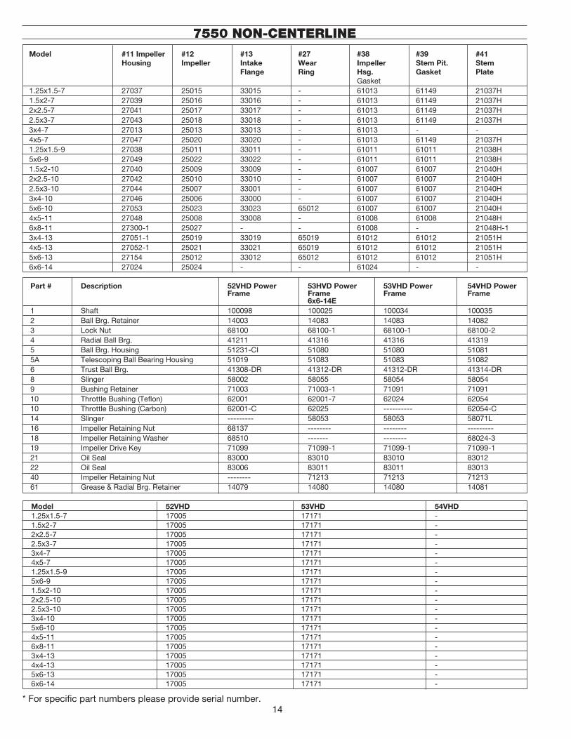
ENGINEER ING DATA CAPACITY AND HEAD IN FEET . . .Gallons per minute (G.P.M.) and Foot heads in the performance charts in this catalog were compiled from actual tests. The Maximum G.P.M. shown is the pump capacity at rated horsepower. The maximum Head in Feet is at full rated speed (60 cycle current). For Maximum G.P.M. all piping should be straight, short and large as possible. Heads and G.P.M. are based on tests with specific gravity of 1 and a temperature of 70°F.HOW TO FIGURE HEAD.. 1. Determine static lift (height liquid is to be raised above reservoir)
2. Determine friction loss (losses due to piping depend on size, length and condition of piping system in relation to G.P.M. needed, see table below. Friction losses also include loss due to valves and fittings)
3. Determine velocity head (refer to table below)
4. Total all three of the above and compare to performance chart. Select pump which delivers total head at desired G.P.M.
Vel......�8.0�
VH
=
Friction of Water in 900 Elbows
(...)PIPE FRICTION Loss.of.Head.In.Feet,.Per.�00.Ft..of.�5-year-old.Ordinary.
Iron.Pipe.Due.to.Friction.
. �.. �.05. �.�. ....... ....... ....... ....... ....... ....... ....... ....... ....... ....... ....... ....... ....... .......
. �.. �.�0. 7.4. �.�0. �.9. ....... ....... ....... ....... ....... ....... ....... ....... ....... ....... ....... ......
. 3.. 3.�6. �5.8. �.80. 4.�. �.��. �.�6. ....... ....... ....... ....... ....... ....... ....... ....... ....... .........
. 4. 4.��. �7.0. �.4�. 7.0. �.49. �.�4. 0.86. 0.57.. 0.63. 0.�6. ....... ....... ....... ....... ....... ......
. 5. 5.�6. 4�.0. 3.0�. �0.5. �.86. 3.�5. �.07. 0.84. 0.79. 0.39. ....... ....... ....... ....... ....... ......
. �0. �0.5�. �47.0. 6.0�. 38.0. 3.7�. ��.7. �.�4. 3.05. �.57. �.43. �.0�. 0.5. 0.65. 0.�7. 0.45. 0.07
. �5. ....... ....... 9.0�. 80.0. 5.60. �5.0. 3.�. 6.5. �.36. 3.0. �.53. �.0. 0.98. 0.36. 0.68. 0.�5
. �0. ....... ....... ��.03. �36.0. 7.44. 4�.0. 4.�9. ��.�. ....... ....... ....... �.83. �.3�. 0.6�. 0.9�. 0.�5
. �5. ....... ....... ....... ....... 9.30. 64.9. 5.36. �6.6. 3.94. 7.8. �.55. �.73. �.63. 0.9�. �.�3. 0.38
. 30.. ....... ....... ....... ....... ��.�5. 89.0. 6.43. �3.5. 4.7�. ��.0. 3.06. 3.84. �.96. �.�9. �.36. 0.54
. 35. ....... ....... ....... ....... �3.0�. ��9.0. 7.5�. 3�.�. 5.5�. �4.7. 3.57. 5.�. �.�0. �.7�. �.59. 0.7�
. 40. ....... ....... ....... ....... �4.88. �5�.0. 8.58. 40.0. 6.3. �8.8. 4.08. 6.6. �.6�. �.�0. �.8�. 0.9�
. 45. ....... ....... ....... ....... ....... ....... 9.65. 50.. 7.08. �3.�. 4.60. 8.�. �.94. �.80. �.05. �.�5
. 50. ....... ....... ....... ....... ....... ....... �0.7�. 60.. 7.87. �8.4. 5.��. 9.9. 3.�7. 3.3�. �.�7. �.38
. 70. ....... ....... ....... ....... ....... ....... �5.0�. ��3.. ��.0�. 53.0. 7.�5. �8.4. 4.58. 6.�. 3.�8. �.57
. 90.. ....... ....... ....... ....... ....... ....... ....... ....... �4.�7. 84.0. 9.�9. �9.4. 5.88. 9.8. 4.09. 4.08
.�00.. ....... ....... ....... ....... ....... ....... ....... ....... �5.74. �0�.0. �0.��. 35.8. 6.54. ��.0. 4.54. 4.96
.��0.. ....... ....... ....... ....... ....... ....... ....... ....... �8.89. �43.0. ��.�5. 50.0. 7.84. �6.8. 5.45. 7.0
.�40.. ....... ....... ....... ....... ....... ....... ....... ....... ��.04. �90.0. �4.30. 67.0. 9.�5. ��.3. 6.35. 9.�
.�60.. ....... ....... ....... ....... ....... ....... ....... ....... ....... ....... �6.34. 86.0. �0.46. �9.0. 7.�6. ��.8
.�80.. ....... ....... ....... ....... ....... ....... ....... ....... ....... ....... �8.38. �07.0. ��.76. 35.7. 8.�7. �4.8
.�00.. ....... ....... ....... ....... ....... ....... ....... ....... ....... ....... �0.4�. ��9.0. �3.07. 43.�. 9.08. �7.8
.��0.. ....... ....... ....... ....... ....... ....... ....... ....... ....... ....... ��.47. �54.0. �4.38. 5�.0. 9.99. ��.3
.�40.. ....... ....... ....... ....... ....... ....... ....... ....... ....... ....... �4.5�. �8�.0. �5.69. 6�.0. �0.89. �5.�
.�60.. ....... ....... ....... ....... ....... ....... ....... ....... ....... ....... �6.55. ���.0. �6.99. 70.0. ��.80. �9.�
.�80.. ....... ....... ....... ....... ....... ....... ....... ....... ....... ....... ....... ....... �8.30. 8�.0. ��.7�. 33.4
.300. ....... ....... ....... ....... ....... ....... ....... ....... ....... ....... ....... ....... �9.6�. 9�.0. �3.6�. 38.0
Vel.. Fric.. Vel.. Fric.. Vel.. Fric.. Vel.. Fric.. Vel.. Fric.. VeI.. Fric.. Vel.. Fric.. Vel.. Fric..Gallons
perMinute
�/�”.Pipe. 3/4”.Pipe. �”.Pipe. �.�/4”.Pipe. �.�/�”.Pipe. �”.Pipe. �.�/�.Pipe. 3”.Pipe
Size.of.Elbow,Inches........................ . �/�. 3/4. �. �.�/4. �.�/�. �. �.�/�. 3. 4. 5. 6Friction.EquivalentFeet.Straight.Pipe...... . 5. 6. 6. 8. 8. 8. ��. �5. �6. �8. �8
To Compute Break Horse Power . GPM.x.H.x.S.G.BHP.=.. 3960.X.pump.Eff.*S.G. = Specific Gravity,BHP.=..Break.Horse.Power,GPM.=..Gallons.per.Minute,H.=..Head.in.FeetEff. = EfficiencyHorse.Power.and.Pressure.(PSI).vary.in.directproportion.to.the.Specific.Gravity.
Effect of Speed Changes
�..Capacity.(GPM).is.directly.proportional.to. the.change.in.speed.�..Head.is.proportional.to.the.square.of.the. change.in.speed.
3..Horse.Power.is.proportional.to.the.cube.of. the.change.in.speed.
Loss.of.Head.in.Feet,.Per.�00.Ft..of.�5-year-oldOrdinary.Iron.Pipe.Due.to.Friction..
. 40.. �.0�. 0.��. ....... ....... ....... .......
.. 45.. �.�7. 0.�8. ....... ....... ....... ......
. 50.. �.�8. 0.34. ....... ....... ....... ......
. 70. �.79. 0.63. �.�4. 0.��. ....... ......
. 75. �.9�. 0.73. �.��. 0.�4. ....... ......
. �00. �.55. �.�3. �.63. 0.39. �.�4. 0.�4
. ��0. 3.06. �.7�. �.96. 0.57. �.4�. 0.�5
. ��5. 3.�9. �.86. �.04. 0.64. �.48. 0.�8
. �50. 3.84. �.55. �.45. 0.88. �.7�. 0.3�
. �75.. 4.45. 3.36. �.86. �.�8. �.00. 0.48
. �00. 5.��. 4.37. 3.�7. �.48. �.�8. 0.6�
. ��5. 6.3�. 6.6�. 3.67. �.86. �.57. 0.74
. �50. 6.40. 6.7�. 4.08. �.�4. �.80. 0.9�
. �75. 7.03. 7.99. 4.50. �.7�. 3.06. �.�5
. 300. 7.66. 9.38. 4.90. 3.�5. 3.40. �.�9.
. 350.. 8.90. ��.3�. 5.7�. 4.�9. 3.98. �.69.
. 400.. �0.�0. �5.8�. 6.54. 5.33. 4.54. �.��.
. 450.. ��.50. �9.74. 7.35. 6.65. 5.��. �.74
. 475.. ��.30. ��.96. 7.88. 7.��. 5.55. 3.��
. 500.. ��.77. �4.08. 8.�7. 8.��. 5.60. 3.�6
. 550.. ....... ....... 9.09. 9.66. 6.�6. 3.93
. 600.. ....... ....... 9.80. ��.34. 6.7�. 4.70
. 650.. ....... ....... �0.6�. �3.�6. 7.�8. 5.60
. 700.. ....... ....... ��.44. �5.��. 7.84. 6.38
. 750.. ....... ....... ��.�6. �7.��. 8.50. 7.00
. 800.. ....... ....... ....... ....... 9.08. 7.90
. 850. ....... ....... ....... ....... 9.58. 8.75
. 900. ....... ....... ....... ....... �0.30. �0.��
. 950. ....... ....... ....... ....... �0.7�. �0.7�
.�000. ....... ....... ....... ....... ��.3�. ��.04��00. ....... ....... ....... ....... ��.50. �4.3���00. ....... ....... ....... ....... �3.5�. �6.69
.Vel.. Fric.. Vel.. Fric.. Vel.. Fric.
Gallonsper
Minute
. 4”.Pipe. 5”.Pipe. 6”.Pipe
Pipe Friction (Continued)

�9
THEORETICAL DISCHARGE OF NOZZLES IN U. S. GALLONS PER MINUTE
NOTE-The actual quantities will vary from these figures, the amount of variation depending upon the shape of nozzle and size of pipe at the point.where the pressure is determined. With smooth taper nozzles the actual discharge is about 94 per cent of the figures given in the labels.
. �0. �3.�. 38.6. 0.37. �.48. 3.3�. 5.9�. �3.3. �3.6. 36.9. 53.�. 7�.4
. �5. 34.6. 47.�5. 0.45. �.84. 4.06. 7.�4. �6.3. �8.9. 45.�. 65.0. 88.5.
. �0. 46.�. 54.55. 0.5�. �.09. 4.69. 8.35. �8.8. 33.4. 5�.�. 75.�. �0�
. �5. 57.7. 6�.0. 0.58. �.34. 5.�5. 9.34. ��.0. 37.3. 58.3. 84.0. ��4.
. 30. 69.3. 66.85. 0.64. �.56. 5.75. �0.�. �3.0. 40.9. 63.9. 9�.0. ��5.
. 35. 80.8. 7�.�. 0.69. �.77. 6.��. ��.�. �4.8. 44.�. 69.0. 99.5. �35
. 40. 9�.4. 77.�. 0.74. �.96. 6.64. ��.8. �6.6. 47.3. 73.8. �06. �45.
. 45. �03.9. 8�.8. 0.78. 3.�3. 7.03. ��.5. �8.�. 50.�. 78.�. ��3. �53.
. 50. ��5.5. 86.�5. 0.83. 3.30. 7.4�. �3.�. �9.7. 5�.8. 8�.5. ��9. �6�.
. 55. ��7.0. 90.4. 0.87. 3.46. 7.77. �3.8. 3�.�. 55.3. 86.4. ��5. �69.
. 60. �38.6. 94.5. 0.90. 3.6�. 8.��. �4.5. 3�.5. 57.8. 90.4. �30. �77
. 65. �50.�. 98.3. 0.94. 3.77. 8.45. �5.�. 33.8. 60.�. 94.0. �36. �84.
. 70. �6�.7. �0�.�. 0.98. 3.9�. 8.78. �5.7. 35.�. 6�.5. 97.7. �4�. �9�.
. 75. �73.�. �05.7. �.0�. 4.05. 9.08. �6.�. 36.4. 64.7. �0�. �46. �98.
. 80. �84.8. �09.�. �.05. 4.�8. 9.39. �6.7. 37.6. 66.8. �04. �50. �05.
. 85. �96.3. ���.5. �.08. 4.3�. 9.67. �7.3. 38.8. 68.9. �08. �55. ���.
. 90. �07.9. ��5.8. �.��. 4.43. 9.95. �7.7. 39.9. 70.8. ���. �60. ��7.
. 95. ��9.4. ��9.0. �.�4. 4.56. �0.�. �8.�. 4�.0. 7�.8. ��4. �64. ��3.
. �00. �30.9. ���.0. �.�7. 4.67. �0.0. �8.7. 4�.�. 74.7. ��7. �68. ��9.
. �05. �4�.4. ��5.0. �.�0. 4.79. �0.8. �9.�. 43.�. 76.5. ��0. �7�. �34.
. ��0. �54.0. ��8.0. �.�3. 4.90. ��.0. �9.6. 44.�. 78.4. ���. �76. �40.
. ��5. �65.5. �30.9. �.�5. 5.0�. ��.�. �0.0. 45.�. 80.�. ��5. �80. �45.
. ��0. �77.�. �33.7. �.�8. 5.��. ��.5. �0.5. 46.0. 8�.8. ��8. �84. �5�.
. ��5. �88.6. �36.4. �.3�. 5.��. ��.7. �0.9. 47.0. 83.5. �30. �88. �56.
. �30. 300.�. �39.�. �.33. 5.33. ��.0. ��.3. 48.0. 85.�. �33. �9�. �6�.
. �35. 3��.7. �4�.8. �.36. 5.43. ��.�. ��.7. 48.9. 86.7. �36. �95. �66.
. �40. 3�3.3. �44.3. �.38. 5.53. ��.4. ��.�. 49.8. 88.4. �38. �99. �7�.
. �45. 334.8. �46.9. �.4�. 5.6�. ��.6. ��.5. 50.6. 89.9. �40. �0�. �75.
. �50. 346.4. �49.5. �.43. 5.7�. ��.9. ��.9. 5�.5. 9�.5. �43. �06. �80.
. �75. 404.�. �6�.4. �.55. 6.�8. �3.9. �4.7. 55.6. 98.8. �54. ���. 30�.
. �00. 46�.9. �7�.6. �.65. 6.6�. �4.8. �6.4. 59.5. �06. �65. �38. 3�3
HEAD DIAMETER.OF.NOZZL.IN.INCHESVelocity.ofDischarge
FeetPer.Second
Pounds Feet 1/16 1/8 3/16 1/4 3/8 1/2 5/8 3/4 7/8
. �0. �3.�. 38.6. 94.5. ��0. �48. �79. ��3. �89. 378. 479. 59�
. �5. 34.6. 47.�5. ��6. �47. �8�. ��9. �60. 354. 463. 585. 7�3.
. �0. 46.�. 54.55. �34. �69. �09. �53. 30�. 409. 535. 676. 835
. �5. 57.7. 6�.0.. �49. �89. �34. �83. 336. 458. 598. 756. 934
. 30. 69.3. 66.85.. �64. �07. �56. 309. 368. 50�. 655. 8�8. �0�3
. 35. 80.8. 7�.�. �77. ��4. �77. 334. 398. 54�. 708. 895. ��06
. 40. 9�.4. 77.�.. �88. �39. �96. 357. 4�5. 578. 756. 957. ��8�
. 45. �03.9. 8�.8.. �00. �53. 3�3. 379. 45�. 6�3. 80�. �0�5. ��5�
. 50. ��5.5. 86.�5.. ���. �67. 330. 399. 475. 647. 845. �070. �3�0
. 55. ��7.0. 90.0.. ���. �80. 346. 4�8. 498. 678. 886. ����. �365
. 60. �38.6. 94.5. �3�. �93. 36�. 438. 5��. 708. 9�6. ��7�. �447
. 65. �50.�. 98.3.. �4�. 305. 376. 455. 54�. 737. 964. ���0. �506
. 70. �6�.7. �0�.�.. �50. 3�7. 39�. 473. 563. 765. �00�. ��67. �565
. 75. �73.�. �05.7.. �59. 3�7. 404. 489. 58�. 79�. �037. �3�0. �6�9
. 80. �84.8. �09.�.. �67. 338. 4�8. 505. 60�. 8�8. �0�0. �354. �67�
. 85. �96.3. ���.5.. �76. 349. 43�. 5��. 6�0. 844. ��03. �395. �7�3
. 90. �07.9. ��5.8.. �84. 359. 443. 536. 638. 868. ��36. �436. �773
. 95. ��9.4. ��9.0.. �9�. 369. 456. 55�. 656. 89�. ��68. �476. �8�4
. �00. �30.9. ���.0.. �99. 378. 467. 565. 67�. 9�5. ��96. �5��. �870
. �05. �4�.4. ��5.0.. 306. 388. 479. 579. 689. 937. ���6. �550. �9�6
. ��0. �54.0. ��8.0.. 3�4. 397. 490. 593. 705. 960. ��55. �588. �96�
. ��5. �65.5. �30.9.. 3�0. 406. 50�. 606. 7�0. 980. ��8�. �6��. �005
. ��0. �77.�. �33.7.. 3�7. 4�4. 5��. 6�9. 736. �00�. �3�0. �639. �050
. ��5. �88.6. �36.4.. 334. 4�3. 5��. 63�. 75�. �0��. �338. �690. �090
. �30. 300.�. �39.�.. 34�. 43�. 533. 645. 767. �043. �365. �7�6. ��3�
. �35. 3��.7. �4�.8.. 347. 439. 543. 656. 780. �063. �390. �759. ��73
. �40. 3�3.3. �44.3.. 354. 448. 553. 668. 795. �08�. �4�5. �790. ����
. �45. 334.8. �46.9.. 360. 455. 56�. 680. 809. ��00. �400. �8�0. ��50
. �50. 346.4. �49.5.. 366. 463. 57�. 69�. 8�4. ���0. �466. �853. ��90
. �75. 404.�. �6�.4.. 395. 500. 6�8. 747. 890. ���0. �58�. �000. �473
. �00. 46�.9. �7�.6. 4�3. 535. 660. 799. 950. ��94. �69�. ��40. �645
HEAD DIAMETER.OF.NOZZL.IN.INCHESVelocity.ofDischarge
FeetPer.Second
Pounds Feet 1 11/8 11/4 13/8 11/2 13/4 2 21/4 21/2

�0
Ruthman...Another Word for Innovation
It began in 1913, servicing me-chanical components of thesteamboatsontheOhioRiver.Thecompanyfounder,AloisRuthman,wasamanofvisionandsawpartof the futureof thecompanywasinthedevelopmentofareliablein-dustrialpump.
In1924,withtheconceptionofthefirstverticalballbearingseal-lesscentrifugalpump,RuthmanPumpandEngineeringfurtheredthedesignonaunitwithaonepiecemotordrivenshaft.Thepumpwascalled“Gusher”,givingbirthtothetradenameGush-erPumps,andthecoiningoftheterm“coolantpump”.
Wantingtocarryonthetraditionofqualityandreliabilitystartedbyhisfather,ThomasR.Ruthmanjoinedthecompanyin1949.Intheearly1990’sThomasR.Ruthman’sson,ThomasG.Ruthmanjoinedthecompany,continuingthissametradition.MaintainingthereputationofGusherPumpsbyinnovationandcustomerser-vice,thecompanyhasgrowntoservicecompaniesworldwide.
Gusher Pumps is a Division ofRuthman CompaniesCorporate Headquarters1212StrengStreetCincinnati,OH45233Phone:513-559-1901Fax:513-559-0035Web:www.ruthmancompanies.com
Gusher Pumps of Dry Ridge22RuthmanDriveDryRidge,KY41035Phone:859-824-5001Fax:859-824-3011Web:www.gusher.com
Gusher Pumps of Williamstown115IndustrialDriveWilliamstown,KY41097Phone:859-824-3100Fax:859-824-7248Web:www.gusher.com
Gusher Pumps of Cincinnati1212StrengStreetCincinnati,OH45233Phone:513-559-1901Fax:513-559-0035Web:www.gusher.com
Gusher Pumps of California8226SaltLakeAvenueCudahy,CA90201Phone:323-773-0847Fax:323-773-0958Email:[email protected]
Gusher Pumps of New Castle403NorthNinthStreetNewCastle,IN47362Phone:765-529-5624Fax:765-521-0008Email:[email protected]
BSM Pump Corp.180FrenchtownRoadNorthKingstown,RI02852Phone:401-471-6350Fax:401-471-6370Web:www.bsmpump.com
Nagle Pumps1249CenterAvenueChicagoHeights,IL60411Phone:708-754-2940Fax:708-754-2944Web:www.naglepumps.com
Wagner Processing – Bay Area23510BernhardtStreetHayward,CA94545Phone:510-786-3929Fax:510-786-3722Web:www.wagnerprocess.com
Wagner Processing – Central Valley3675N.WilcoxStreet#CStockton,CA95215Phone:209-931-0100Fax:209-931-7910Web: www.wagnerprocess.com
Great Lakes Pump & Supply Co.1075NaughtonTroy,MI48083Phone:248-528-9100Fax:248-528-9015Web:www.greatlakespump.com
Process Systems, Inc.Michigan, Main Headquarters23633PinewoodWarren,MI48091Phone:586-757-5711Fax:586-758-6996Web: www.INFOatpsi4pumps.comIndiana485NStateRoute3431SouthMellott,IN47958Phone:765-295-2206Fax:765-295-2243Web:www.process-systems-inc.com
Worldwide:
Ruthmann PumpenNorthbergerStrabe60EschweilerGermanyD-52249Phone:+49(0)240355950Fax:+49(0)2403559520Web:www.ruthmannpumpen.deBirmingham PumpUnit7NetworkParkDuddestonMillRoadSaltley,BirminghamEnglandB81AUPhone:+44(0)1215033000Fax:+44(0)1215033002Web:www.birminghampumps.co.uk
Guan Shen Industrial Pumps(Shanghai) Company
Gusher Pumps (Shanghai) Co., Ltd.BuildingD,Room416No.188EastJiagwanRoadShanghai,200081P.R.CHINA
Phone: 86-21-33872056Phone:86-21-33872058Fax: 86-21-33872057
86-21-33872056 86-21-33872058 86-21-33872057