Embed Size (px)
Citation preview
75178 Federal Register / Vol. 80, No. 230 / Tuesday, December 1, 2015 / Rules and Regulations
ENVIRONMENTAL PROTECTION AGENCY
40 CFR Parts 60 and 63
[EPA–HQ–OAR–2010–0682; FRL–9935–40– OAR]
RIN 2060–AQ75
Petroleum Refinery Sector Risk and Technology Review and New Source Performance Standards
AGENCY: Environmental Protection Agency (EPA). ACTION: Final rule.
SUMMARY: This action finalizes the residual risk and technology review conducted for the Petroleum Refinery source categories regulated under national emission standards for hazardous air pollutants (NESHAP) Refinery MACT 1 and Refinery MACT 2. It also includes revisions to the Refinery MACT 1 and MACT 2 rules in accordance with provisions regarding establishment of MACT standards. This action also finalizes technical corrections and clarifications for the new source performance standards (NSPS) for petroleum refineries to improve consistency and clarity and address issues related to a 2008 industry petition for reconsideration. Implementation of this final rule will result in projected reductions of 5,200 tons per year (tpy) of hazardous air pollutants (HAP) which will reduce cancer risk and chronic health effects. DATES: This final action is effective on February 1, 2016. The incorporation by reference of certain publications for part 63 listed in the rule is approved by the Director of the Federal Register as of February 1, 2016. The incorporation by reference of certain publications for part 60 listed in the rule were approved by the Director of the Federal Register as of June 24, 2008. ADDRESSES: The Environmental Protection Agency (EPA) has established a docket for this action under Docket ID No. EPA–HQ–OAR–2010–0682. All documents in the docket are listed on the www.regulations.gov Web site. Although listed in the index, some information is not publicly available, e.g., confidential business information (CBI) or other information whose disclosure is restricted by statute. Certain other material, such as copyrighted material, is not placed on the Internet and will be publicly available only in hard copy form. Publicly available docket materials are available either electronically through http://www.regulations.gov, or in hard copy at the EPA Docket Center, WJC
West Building, Room Number 3334, 1301 Constitution Ave. NW., Washington, DC. The Public Reading Room hours of operation are 8:30 a.m. to 4:30 p.m. Eastern Standard Time (EST), Monday through Friday. The telephone number for the Public Reading Room is (202) 566–1744, and the telephone number for the Air and Radiation Docket and Information Center is (202) 566–1742. FOR FURTHER INFORMATION CONTACT: For questions about this final action, contact Ms. Brenda Shine, Sector Policies and Programs Division, Refining and Chemicals Group (E143–01), Office of Air Quality Planning and Standards, U.S. Environmental Protection Agency, Research Triangle Park, North Carolina, 27711; telephone number: (919) 541– 3608; fax number: (919) 541–0246; and email address: [email protected]. For specific information regarding the risk modeling methodology, contact Mr. Ted Palma, Health and Environmental Impacts Division (C539–02), Office of Air Quality Planning and Standards, U.S. Environmental Protection Agency, Research Triangle Park, North Carolina 27711; telephone number: (919) 541– 5470; fax number: (919) 541–0840; and email address: [email protected]. For information about the applicability of the NESHAP to a particular entity, contact Ms. Maria Malave, Office of Enforcement and Compliance Assurance, U.S. Environmental Protection Agency, William Jefferson Clinton Building, 1200 Pennsylvania Ave. NW., Washington, DC 20460; telephone number: (202) 564–7027; fax number: (202) 564–0050; and email address: [email protected]. SUPPLEMENTARY INFORMATION:
Preamble Acronyms and Abbreviations. We use multiple acronyms and terms in this preamble. While this list may not be exhaustive, to ease the reading of this preamble and for reference purposes, the EPA defines the following terms and acronyms here: 10/25 tpy emissions equal to or greater than
10 tons per year of a single pollutant or 25 tons per year of cumulative pollutants
AEGL acute exposure guideline levels APCD air pollution control devices API American Petroleum Institute BAAQMD Bay Area Air Quality
Management District BDT best demonstrated technology BLD bag leak detectors BSER best system of emission reductions Btu/ft2 British thermal units per square foot Btu/scf British thermal units per standard
cubic foot CAA Clean Air Act CBI confidential business information CCU catalytic cracking units CDX Central Data Exchange
CEDRI Compliance and Emissions Data Reporting Interface
CEMS continuous emission monitoring system
CFR Code of Federal Regulations CO carbon monoxide CO2 carbon dioxide CO2e carbon dioxide equivalents COMS continuous opacity monitoring
system COS carbonyl sulfide CPMS continuous parameter monitoring
system CRA Congressional Review Act CRU catalytic reforming units CS2 carbon disulfide DCU delayed coking units EPA Environmental Protection Agency ERPG emergency response and planning
guidelines ERT Electronic Reporting Tool ESP electrostatic precipitator FCCU fluid catalytic cracking unit FGCD fuel gas combustion device FMP flare management plan FR Federal Register FTIR Fourier transform infrared
spectroscopy GC gas chromatograph GHG greenhouse gases H2S hydrogen sulfide HAP hazardous air pollutants HCl hydrogen chloride HCN hydrogen cyanide HF hydrogen fluoride HFC highest fenceline concentration HI hazard index HQ hazard quotient ICR information collection request IRIS Integrated Risk Information System km kilometers LAER lowest achievable emission rate lb/day pounds per day LDAR leak detection and repair LEL lower explosive limit LTD long tons per day MACT maximum achievable control
technology MIR maximum individual risk mph miles per hour MPV miscellaneous process vent NAICS North American Industry
Classification System NESHAP National Emissions Standards for
Hazardous Air Pollutants NFS near-field interfering source NHVCZ combustion zone net heating value Ni nickel NOX nitrogen oxides NRDC Natural Resources Defense Council NSPS new source performance standards NTTAA National Technology Transfer and
Advancement Act OAQPS Office of Air Quality Planning and
standards OECA Office of Enforcement and
Compliance Assurance OEHHA Office of Environmental Health
Hazard Assessment OEL open-ended line OMB Office of Management and Budget PM particulate matter PM2.5 particulate matter 2.5 micrometers in
diameter and smaller ppbv parts per billion by volume ppm parts per million
VerDate Sep<11>2014 23:11 Nov 30, 2015 Jkt 238001 PO 00000 Frm 00002 Fmt 4701 Sfmt 4700 E:\FR\FM\01DER2.SGM 01DER2tkel
ley
on D
SK
3SP
TV
N1P
RO
D w
ith R
ULE
S2

75179 Federal Register / Vol. 80, No. 230 / Tuesday, December 1, 2015 / Rules and Regulations
1 This term is common vernacular to describe the variety of devices regulated as pressure relief valves subject to the requirements in 40 CFR part 63 subpart CC.
ppmv parts per million by volume PRA Paperwork Reduction Act PRD pressure relief device 1 psia pounds per square inch absolute psig pounds per square inch gauge REL reference exposure level REM Model Refinery Emissions Model RFA Regulatory Flexibility Act RTC response to comment RTR Risk and Technology Review SAB Science Advisory Board SBA Small Business Administration SCAQMD South Coast Air Quality
Management District SCR selective catalytic reduction SISNOSE significant economic impact on a
substantial number of small entities SO2 sulfur dioxide SRP sulfur recovery plant SRU sulfur recovery unit SSM startup, shutdown and malfunction TOSHI target organ-specific hazard index tpy tons per year UMRA Unfunded Mandates Reform Act URE unit risk estimate UV–DOAS ultraviolet differential optical
absorption spectroscopy VCS voluntary consensus standards VOC volatile organic compounds °F degrees Fahrenheit DC the concentration difference between
the highest measured concentration and the lowest measured concentration
mg/m3 micrograms per cubic meter
Background Information. On June 30, 2014, the EPA proposed revisions to both of the petroleum refinery NESHAP based on our residual risk and technology review (RTR). In that action, we also proposed to revise the NESHAP pursuant to CAA section 112(d)(2) and (3), to revise the SSM provisions in the NESHAP, and to make technical corrections to the NSPS to address issues related to reconsideration of the final NSPS subpart Ja rule in 2008. In this action, we are finalizing decisions and revisions for these rules. We summarize some of the more significant comments received regarding the proposed rule and provide our responses in this preamble. A summary of all other public comments on the proposal and the EPA’s responses to those comments is provided in the ‘‘Response to Comment’’ document, which is available in Docket ID No. EPA–HQ–OAR–2010–0682. The ‘‘track changes’’ version of the regulatory language that incorporates the changes in this final action is also available in the docket for this rulemaking.
Organization of this Document. This preamble is organized as follows: I. General Information
A. Does this action apply to me? B. Where can I get a copy of this document
and other related information?
C. Judicial Review and Administrative Reconsideration
II. Background A. What is the statutory authority for this
action? B. How do the NESHAP and NSPS regulate
air pollutant emissions from refineries? C. What changes did we propose for the
Petroleum Refinery NESHAP and NSPS in our June 30, 2014 RTR proposal?
III. What is included in this final rule? A. What are the final NESHAP
amendments based on the risk review for the Petroleum Refinery source categories?
B. What are the final NESHAP amendments based on the technology review for the Petroleum Refinery source categories?
C. What are the final NESHAP amendments pursuant to section 112(d)(2) & (3) for the Petroleum Refinery source categories?
D. What are the final NESHAP amendments addressing emissions during periods of SSM?
E. What other revisions to the NESHAP and NSPS are being promulgated?
F. What are the requirements for submission of performance test data to the EPA?
G. What are the effective and compliance dates of the NESHAP and NSPS?
H. What materials are being incorporated by reference?
IV. What is the rationale for our final decisions and amendments to the Petroleum Refinery NESHAP and NSPS?
A. Residual Risk Review for the Petroleum Refinery Source Categories
B. Technology Review for the Petroleum Refinery Source Categories
C. Refinery MACT Amendments Pursuant to CAA section 112(d)(2) and (d)(3)
D. NESHAP Amendments Addressing Emissions During Periods of SSM
E. Technical Amendments to Refinery MACT 1 and 2
F. Technical Amendments to Refinery NSPS Subparts J and Ja
V. Summary of Cost, Environmental, and Economic Impacts and Additional Analyses Conducted
A. What are the affected facilities, the air quality impacts and cost impacts?
B. What are the economic impacts? C. What are the benefits? D. Impacts of This Rulemaking on
Environmental Justice Populations E. Impacts of This Rulemaking on
Children’s Health VI. Statutory and Executive Order Reviews
A. Executive Orders 12866: Regulatory Planning and Review and Executive Order 13563: Improving Regulation and Regulatory Review
B. Paperwork Reduction Act (PRA) C. Regulatory Flexibility Act (RFA) D. Unfunded Mandates Reform Act
(UMRA) E. Executive Order 13132: Federalism F. Executive Order 13175: Consultation
and Coordination With Indian Tribal Governments
G. Executive Order 13045: Protection of Children From Environmental Health Risks and Safety Risks
H. Executive Order 13211: Actions Concerning Regulations That Significantly Affect Energy Supply, Distribution or Use
I. National Technology Transfer and Advancement Act (NTTAA) and 1 CFR part 51
J. Executive Order 12898: Federal Actions To Address Environmental Justice in Minority Populations and Low-Income Populations
K. Congressional Review Act (CRA)
I. General Information
A. Does this action apply to me?
Regulated Entities. Categories and entities potentially regulated by this action are shown in Table 1 of this preamble.
TABLE 1—INDUSTRIAL SOURCE CAT-EGORIES AFFECTED BY THIS FINAL ACTION
NESHAP and source category NAICS a Code
Petroleum Refining Industry ......... 324110
a North American Industry Classification System.
Table 1 of this preamble is not intended to be exhaustive, but rather to provide a guide for readers regarding entities likely to be affected by the final action for the source categories listed. To determine whether your facility is affected, you should examine the applicability criteria in the appropriate NESHAP or NSPS. If you have any questions regarding the applicability of any aspect of these NESHAP or NSPS, please contact the appropriate person listed in the preceding FOR FURTHER INFORMATION CONTACT section of this preamble.
B. Where can I get a copy of this document and other related information?
In addition to being available in the docket, an electronic copy of this final action will also be available on the Internet through the Technology Transfer Network (TTN) Web site, a forum for information and technology exchange in various areas of air pollution control. Following signature by the EPA Administrator, the EPA will post a copy of this final action at: http://www.epa.gov/ttn/atw/petref.html. Following publication in the Federal Register, the EPA will post the Federal Register version and key technical documents at this same Web site.
Additional information is available on the RTR Web site at http://www.epa.gov/ttn/atw/rrisk/rtrpg.html. This information includes an overview of the RTR program, links to project Web sites
VerDate Sep<11>2014 23:11 Nov 30, 2015 Jkt 238001 PO 00000 Frm 00003 Fmt 4701 Sfmt 4700 E:\FR\FM\01DER2.SGM 01DER2tkel
ley
on D
SK
3SP
TV
N1P
RO
D w
ith R
ULE
S2
75180 Federal Register / Vol. 80, No. 230 / Tuesday, December 1, 2015 / Rules and Regulations
2 The U.S. Court of Appeals has affirmed this approach of implementing CAA section 112(f)(2)(A): NRDC v. EPA, 529 F.3d 1077, 1083 (D.C. Cir. 2008) (‘‘If EPA determines that the existing technology-based standards provide an ‘ample margin of safety,’ then the Agency is free to readopt those standards during the residual risk rulemaking.’’).
for the RTR source categories, and detailed emissions and other data we used as inputs to the risk assessments.
C. Judicial Review and Administrative Reconsideration
Under CAA section 307(b)(1), judicial review of this final action is available only by filing a petition for review in the United States Court of Appeals for the District of Columbia Circuit by February 1, 2016. Under CAA section 307(b)(2), the requirements established by this final rule may not be challenged separately in any civil or criminal proceedings brought by the EPA to enforce the requirements.
Section 307(d)(7)(B) of the CAA further provides that ‘‘[o]nly an objection to a rule or procedure which was raised with reasonable specificity during the period for public comment (including any public hearing) may be raised during judicial review.’’ This section also provides a mechanism for the EPA to reconsider the rule ‘‘[i]f the person raising an objection can demonstrate to the Administrator that it was impracticable to raise such objection within [the period for public comment] or if the grounds for such objection arose after the period for public comment (but within the time specified for judicial review) and if such objection is of central relevance to the outcome of the rule.’’ Any person seeking to make such a demonstration should submit a Petition for Reconsideration to the Office of the Administrator, U.S. EPA, Room 3000, WJC Building, 1200 Pennsylvania Ave. NW., Washington, DC 20460, with a copy to both the person(s) listed in the preceding FOR FURTHER INFORMATION CONTACT section, and the Associate General Counsel for the Air and Radiation Law Office, Office of General Counsel (Mail Code 2344A), U.S. EPA, 1200 Pennsylvania Ave. NW., Washington, DC 20460.
II. Background
A. What is the statutory authority for this action?
1. NESHAP Section 112 of the CAA establishes a
two-stage regulatory process to address emissions of hazardous air pollutants (HAP) from stationary sources. In the first stage, we must identify categories of sources emitting one or more of the HAP listed in CAA section 112(b) and then promulgate technology-based NESHAP for those sources. ‘‘Major sources’’ are those that emit, or have the potential to emit, any single HAP at a rate of 10 tons per year (tpy) or more, or 25 tpy or more of any combination of
HAP. For major sources, these standards are commonly referred to as maximum achievable control technology (MACT) standards and must reflect the maximum degree of emission reductions of HAP achievable (after considering cost, energy requirements, and non-air quality health and environmental impacts). In developing MACT standards, CAA section 112(d)(2) directs the EPA to consider the application of measures, processes, methods, systems or techniques, including but not limited to those that reduce the volume of or eliminate HAP emissions through process changes, substitution of materials, or other modifications; enclose systems or processes to eliminate emissions; collect, capture, or treat HAP when released from a process, stack, storage, or fugitive emissions point; are design, equipment, work practice, or operational standards; or any combination of the above.
For these MACT standards, the statute specifies certain minimum stringency requirements, which are referred to as MACT floor requirements, and which may not be based on cost considerations. See CAA section 112(d)(3). For new sources, the MACT floor cannot be less stringent than the emission control achieved in practice by the best-controlled similar source. The MACT standards for existing sources can be less stringent than floors for new sources, but they cannot be less stringent than the average emission limitation achieved by the best- performing 12-percent of existing sources in the category or subcategory (or the best-performing 5 sources for categories or subcategories with fewer than 30 sources). In developing MACT standards, we must also consider control options that are more stringent than the floor, under CAA section 112(d)(2). We may establish standards more stringent than the floor, based on the consideration of the cost of achieving the emissions reductions, any non-air quality health and environmental impacts, and energy requirements.
In the second stage of the regulatory process, the CAA requires the EPA to undertake 2 different analyses, which we refer to as the technology review and the residual risk review. Under the technology review, we must review the technology-based standards and revise them ‘‘as necessary (taking into account developments in practices, processes, and control technologies)’’ no less frequently than every eight years, pursuant to CAA section 112(d)(6). Under the residual risk review, we must evaluate the risk to public health remaining after application of the
technology-based standards and revise the standards, if necessary, to provide an ample margin of safety to protect public health or to prevent, taking into consideration costs, energy, safety and other relevant factors, an adverse environmental effect. The residual risk review is required within eight years after promulgation of the technology- based standards, pursuant to CAA section 112(f). In conducting the residual risk review, if the EPA determines that the current standards provide an ample margin of safety to protect public health, it is not necessary to revise the MACT standards pursuant to CAA section 112(f).2 For more information on the statutory authority for this rule, see 79 FR 36879.
2. NSPS Section 111 of the CAA establishes
mechanisms for controlling emissions of air pollutants from stationary sources. Section 111(b) of the CAA provides authority for the EPA to promulgate NSPS that apply only to newly constructed, reconstructed and modified sources. Once the EPA has elected to set NSPS for new and modified sources in a given source category, CAA section 111(d) calls for regulation of existing sources, with certain exceptions explained below.
Specifically, section 111(b) of the CAA requires the EPA to establish emission standards for any category of new and modified stationary sources that the Administrator, in his or her judgment, finds ‘‘causes, or contributes significantly to, air pollution which may reasonably be anticipated to endanger public health or welfare.’’ The EPA has previously made endangerment findings under this section of the CAA for more than 60 stationary source categories and subcategories that are now subject to NSPS.
Section 111 of the CAA gives the EPA significant discretion to identify the affected facilities within a source category that should be regulated. To define the affected facilities, the EPA can use size thresholds for regulation and create subcategories based on source type, class or size. Emission limits also may be established either for equipment within a facility or for an entire facility. For listed source categories, the EPA must establish ‘‘standards of performance’’ that apply
VerDate Sep<11>2014 23:11 Nov 30, 2015 Jkt 238001 PO 00000 Frm 00004 Fmt 4701 Sfmt 4700 E:\FR\FM\01DER2.SGM 01DER2tkel
ley
on D
SK
3SP
TV
N1P
RO
D w
ith R
ULE
S2
75181 Federal Register / Vol. 80, No. 230 / Tuesday, December 1, 2015 / Rules and Regulations
3 Specific statutory and regulatory provisions define what constitutes a modification or reconstruction of a facility. 40 CFR 60.14 provides that an existing facility is modified and, therefore, subject to an NSPS, if it undergoes any physical change in the method of operation which increases the amount of any air pollutant emitted by such source or which results in the emission of any air pollutant not previously emitted. 40 CFR 60.15, in turn, provides that a facility is reconstructed if components are replaced at an existing facility to such an extent that the capital cost of the new equipment/components exceed 50-percent of what is believed to be the cost of a completely new facility.
to sources that are constructed, modified or reconstructed after the EPA proposes the NSPS for the relevant source category.3
The EPA also has significant discretion to determine the appropriate level for the standards. Section 111(a)(1) of the CAA provides that NSPS are to reflect the degree of emission limitation achievable through the application of the best system of emission reduction which (taking into account the cost of achieving such reduction and any non- air quality health and environmental impact and energy requirements) the Administrator determines has been adequately demonstrated. This level of control is commonly referred to as best demonstrated technology (BDT) or the best system of emission reduction (BSER). The standard that the EPA develops, based on the BSER achievable at that source, is commonly a numerical emission limit, expressed as a performance level (i.e., a rate-based standard). Generally, the EPA does not prescribe a particular technological system that must be used to comply with a NSPS. Rather, sources remain free to elect whatever combination of measures will achieve equivalent or greater control of emissions.
Costs are also considered in evaluating the appropriate standard of performance for each category or subcategory. The EPA generally compares control options and estimated costs and emission impacts of multiple, specific emission standard options under consideration. As part of this analysis, the EPA considers numerous factors relating to the potential cost of the regulation, including industry organization and market structure, control options available to reduce emissions of the regulated pollutant(s) and costs of these controls.
B. How do the NESHAP and NSPS regulate air pollutant emissions from refineries?
The EPA promulgated the petroleum refinery NESHAP pursuant to CAA section 112(d)(2) and (3) for refineries located at major sources in two separate rules. On August 18, 1995, the first
petroleum refinery MACT standard was promulgated in 40 CFR part 63, subpart CC (60 FR 43620). This rule is known as ‘‘Refinery MACT 1’’ and covers the ‘‘Sources Not Distinctly Listed,’’ meaning it includes all emissions sources from petroleum refinery process units, except those listed separately under the section 112(c) source category list and expected to be regulated by other MACT standards (for example, boilers and process heaters). Some of the emission sources regulated in Refinery MACT 1 include miscellaneous process vents (MPV), storage vessels, wastewater, equipment leaks, gasoline loading racks, marine tank vessel loading and heat exchange systems.
On April 11, 2002 (67 FR 17762), EPA promulgated a second MACT standard regulating certain process vents that were listed as a separate source category under CAA section 112(c) and that were not addressed as part of the Refinery MACT 1. This standard, which is referred to as ‘‘Refinery MACT 2’’, covers process vents on catalytic cracking units (CCU) (including FCCU), CRU and SRU and is codified as 40 CFR part 63, subpart UUU.
Finally, on October 28, 2009, we revised Refinery MACT 1 by adding MACT standards for heat exchange systems, which the EPA had not addressed in the original 1995 Refinery MACT 1 rule (74 FR 55686). In this same 2009 action, we updated the cross- references to the General Provisions in 40 CFR part 63. On June 20, 2013 (78 FR 37133), we promulgated minor revisions to the heat exchange provisions of Refinery MACT 1.
On September 27, 2012, Air Alliance Houston, California Communities Against Toxics and other environmental and public health groups filed a lawsuit alleging that the EPA missed statutory deadlines to review and revise Refinery MACT 1 and 2. The EPA reached an agreement to settle that litigation and entered into a Consent Decree. The Consent Decree provides for the Administrator to sign a final action no later than September 30, 2015.
Refinery NSPS subparts J and Ja regulated criteria pollutant emissions, including particulate matter (PM), sulfur dioxide (SO2), nitrogen oxides (NOX) and carbon monoxide (CO) from FCCU catalyst regenerators, fuel gas combustion devices (FGCD) and sulfur recovery plants. Refinery NSPS subpart Ja also regulates criteria pollutant emissions from fluid coking units and DCU.
The NSPS for petroleum refineries (40 CFR part 60, subpart J) were promulgated in 1974, amended in 1976 and amended again in 2008, following
a review of the standards. As part of the review that led to the 2008 amendments to the Refinery NSPS subpart J, the EPA developed separate standards of performance for new process units (40 CFR part 60, subpart Ja). However, the EPA received multiple petitions for reconsideration on issues related to those standards. The Administrator granted the petitions for reconsideration. The EPA addressed petition issues related to process heaters and flares by promulgating amendments to the Refinery NSPS subparts J and Ja on September 12, 2012 (77 FR 56422). In this action, we are finalizing technical corrections and clarifications to NSPS subparts J and Ja raised by American Petroleum Institute (API) in their 2008 petition for reconsideration that were not addressed by the final NSPS amendments of 2012.
The petroleum refining industry consists of facilities that engage in converting crude oil into refined products, including liquefied petroleum gas, gasoline, kerosene, aviation fuel, diesel fuel, fuel oils, lubricating oils and feedstocks for the petrochemical industry. Currently, 142 facilities have emission sources regulated by either or both Refinery MACT 1 and 2.
Petroleum refinery activities start with the receipt of crude oil for storage at the refinery, include all the petroleum handling and refining operations, and terminate with loading of refined products into pipelines, tank or rail cars, tank trucks, or ships or barges that take products from the refinery to distribution centers. Petroleum-specific process units include FCCU and CRU. Other units and processes found at petroleum refineries (as well as at many other types of manufacturing facilities) include storage vessels and wastewater treatment plants. HAP emitted by this industry include organics (e.g., acetaldehyde, benzene, formaldehyde, hexane, phenol, naphthalene, 2- methylnaphthalene, dioxins, furans, ethyl benzene, toluene and xylene); reduced sulfur compounds (i.e., carbonyl sulfide (COS), carbon disulfide (CS2))); inorganics (e.g., hydrogen chloride (HCl), hydrogen cyanide (HCN), chlorine, hydrogen fluoride (HF)); and metals (e.g., antimony, arsenic, beryllium, cadmium, chromium, cobalt, lead, mercury, manganese and nickel (Ni)). This industry also emits criteria pollutants and other non-HAP, including NOX, PM, SO2, volatile organic compounds (VOC), CO, greenhouse gases (GHG) and total reduced sulfur.
VerDate Sep<11>2014 23:11 Nov 30, 2015 Jkt 238001 PO 00000 Frm 00005 Fmt 4701 Sfmt 4700 E:\FR\FM\01DER2.SGM 01DER2tkel
ley
on D
SK
3SP
TV
N1P
RO
D w
ith R
ULE
S2
75182 Federal Register / Vol. 80, No. 230 / Tuesday, December 1, 2015 / Rules and Regulations
C. What changes did we propose for the Petroleum Refinery NESHAP and NSPS in our June 30, 2014, RTR proposal?
On June 30, 2014, the EPA published a proposed rule in the Federal Register addressing the RTR for the Petroleum Refinery NESHAP, 40 CFR part 63, subparts CC and UUU. The proposal also included changes pursuant to section 112(d)(2) and (3) and technical revisions to the NSPS. Specifically, we proposed:
(1) Pursuant to CAA sections 112(d)(2) and (3):
a. Refinery MACT 1: • Adding MACT Standards for DCU
decoking operations. • Adding operational requirements
for flares used as APCD in Refinery MACT 1 and 2.
• Adding requirements and clarifications for vent control bypasses in Refinery MACT 1.
b. Refinery MACT 2: • Revising the CRU purge vent
exemption. (2) Pursuant to CAA sections
112(d)(6) and 112(f)(2): • Revising Refinery MACT 1 to cross-
reference the corresponding storage vessel requirements in the Generic MACT (40 CFR part 63, subpart WW, as applicable), and revising the definition of Group 1 storage vessels to include smaller capacity storage vessels and to include storage vessels storing materials with lower vapor pressures.
(3) Pursuant to CAA section 112(d)(6): a. Refinery MACT 1: • Allowing refineries to meet the leak
detection and repair (LDAR) requirements in Refinery MACT 1 by monitoring for leaks using optical gas imaging in place of EPA Method 21, once the monitoring protocol set forth in Appendix K is promulgated.
• Amending the Marine Tank Vessel Loading Operations NESHAP, 40 CFR part 63, subpart Y, to delete the exclusion for marine vessel loading operations at petroleum refineries.
• Establishing a fenceline monitoring work practice standard to improve the management of fugitive emissions.
b. Refinery MACT 2: • Incorporating requirements
consistent with those in Refinery NSPS subpart Ja for FCCU including:
• Requiring the use of 3-hour averages rather than daily averages for parameter operating limits (e.g., depending on the type of control device: Opacity, total power, secondary current, pressure drop, and/or liquid-to-gas ratio).
• Removing the Refinery NSPS subpart J incremental PM emissions allowance for post combustion devices
when burning liquid or solid fuels, and removing the 30 percent opacity limit for units complying with NSPS subpart J.
• Adding requirements for FCCU controls to include bag leak detectors (BLD) as an option to continuous opacity monitoring system (COMS).
• Incorporating total power and the secondary current operating limits for electrostatic precipitators (ESP).
• Requiring daily checks of the air or water pressure to the spray nozzles on jet ejector-type wet scrubber or other type of wet scrubber equipped with atomizing spray nozzles.
• Requiring FCCU periodic performance testing on a frequency of once every 5 years, as opposed to the current rule, which only requires an initial performance test.
• Including a correlation equation for the use of oxygen-enriched air for SRU.
• Allowing SRU subject to Refinery NSPS subpart Ja with a capacity greater than 20 long tons per day (LTD) to comply with Refinery NSPS subpart Ja as a means of complying with Refinery MACT 2.
(4) Other proposed changes include: • Removing exemptions from the rule
requirements for periods of SSM in order to ensure that the NESHAP are consistent with the court decision in Sierra Club v. EPA, 551 F. 3d 1019 (D.C. Cir. 2008).
• Clarifying requirements related to open-ended valves or lines.
• Adding electronic reporting requirements.
• Updating the General Provisions cross-reference tables.
• Making technical corrections and clarifications to NSPS subparts J and Ja.
III. What is included in this final rule?
This action finalizes the EPA’s determinations pursuant to the RTR provisions of CAA section 112 for the Petroleum Refinery source categories and amends the Petroleum Refinery NESHAP based on those determinations. This action also finalizes other changes to the NESHAP including revising Refinery MACT 1 and 2 pursuant to CAA section 112 (d)(2) and (3), including revising requirements for flares and pressure relief devices (PRD). This action finalizes changes to the SSM provisions to ensure that the subparts are consistent with the court decision in Sierra Club v. EPA, 551 F. 3d 1019 (D.C. Cir. 2008), adds electronic reporting requirements in Refinery MACT 1 and 2; and updates the General Provisions cross-reference tables. Finally, this action finalizes technical corrections and clarifications to Refinery NSPS
subparts J and Ja to address issues raised in the reconsideration of these rules.
A. What are the final NESHAP amendments based on the risk review for the Petroleum Refinery source categories?
The EPA is promulgating final amendments to the Petroleum Refinery NESHAP pursuant to CAA section 112(f) that expand the existing Refinery MACT 1 control requirements and extend these requirements to smaller tanks and tanks with lower vapor pressures. Specifically, consistent with the proposal, the EPA is amending Refinery MACT 1 by revising the definition of Group 1 storage vessels to include storage vessels with capacities greater than or equal to 20,000 gallons but less than 40,000 gallons if the maximum true vapor pressure is 1.0 psia or greater and to include storage tanks greater than 40,000 gallons if the maximum true vapor pressure is 0.75 psia or greater. The EPA is also adding a cross-reference to the storage vessel requirements in the Generic MACT (40 CFR part 63, subpart WW and subpart CC), which include requirements for guide pole controls and other fittings as well as inspection requirements. After considering the public comments, the final amendments include minor changes from our proposed requirements to clarify language and correct typographical and referencing errors.
B. What are the final NESHAP amendments based on the technology review for the Petroleum Refinery source categories?
1. Refinery MACT 1
We determined that there are developments in practices, processes and control technologies that warrant revisions to the MACT standards for this source category. Therefore, to satisfy the requirements of CAA section 112(d)(6), we are revising the MACT standards to amend 40 CFR part 63, subpart Y to delete the exclusion for marine vessel loading operations at petroleum refineries. Removing this exclusion will require small marine vessel loading operations (i.e., operations with HAP emissions less than 10/25 tpy) and offshore marine vessel loading operations to use submerged filling based on the cargo filling line requirements in 46 CFR 153.282, as proposed.
We are also finalizing a fenceline monitoring work practice standard to improve the management of fugitive emissions and finalizing EPA Methods 325A and 325B to support the work
VerDate Sep<11>2014 23:11 Nov 30, 2015 Jkt 238001 PO 00000 Frm 00006 Fmt 4701 Sfmt 4700 E:\FR\FM\01DER2.SGM 01DER2tkel
ley
on D
SK
3SP
TV
N1P
RO
D w
ith R
ULE
S2

75183 Federal Register / Vol. 80, No. 230 / Tuesday, December 1, 2015 / Rules and Regulations
practice, with some changes from proposal to address issues raised by commenters. Key revisions include: New provisions for reduced monitoring for facilities with consistently low fenceline concentrations; requirements for alternatives to passive monitoring; revised placement guidance to allow perimeter monitoring within a facility’s property boundary provided all sources are encompassed within the monitoring perimeter; reductions in the number of monitors required for subareas and segregated areas; clarifications on monitor placement for internal roadways or other right-of-ways and marine docks; and revised timelines for submitting periodic reports (quarterly rather than semiannually) and implementing the work practice standard (2 years after promulgation rather than 3 years as proposed). We are also revising Refinery MACT 1 storage vessel requirements as described above under the risk review, as proposed.
2. Refinery MACT 2 We determined that there are
developments in practices, processes and control technologies that warrant revisions to the MACT standards for this source category. Therefore, to satisfy the requirements of CAA section 112(d)(6), we are revising the Refinery MACT 2 standard for FCCU subject to Refinery NSPS subpart J or those electing to comply with the Refinery NSPS subpart J requirements. As proposed, we are removing the incremental PM limit when burning liquid or solid fuels. We are finalizing a 20-percent opacity operating limit evaluated on a 3-hour average, which differs from the proposal to eliminate the 30-percent opacity limit and instead allow only for a site-specific opacity operating limit or control device parameter monitoring. As proposed, we are finalizing requirements to make Refinery MACT 2 consistent with Refinery NSPS subpart Ja for FCCU by including 3-hour averages rather than daily averages for parameter operating limits, and by including 3-hour averages rather than daily averages for the site- specific opacity operating limit. We are also finalizing requirements, as proposed, for FCCU controls to include adding BLD as an option to COMS, incorporating total power and the secondary current operating limits for ESP and requiring daily checks of the air or water pressure to the spray nozzles on jet ejector-type wet scrubbers or other types of wet scrubbers equipped with atomizing spray nozzles.
Finally, we are finalizing, as proposed, requirements for FCCU periodic performance testing at a frequency of once every 5 years rather
than the current requirements for a one- time initial performance test. However, for owners or operators complying with the Refinery NSPS subpart J option (with the 20-percent opacity operating limit discussed above), if the PM emissions are within 80-percent of the PM limit during any periodic performance test (i.e., emissions exceed 0.8 lb PM/1,000 lbs of coke burn-off), the refinery owner or operator must conduct subsequent performance tests on an annual basis. Based on comments received, we are also adding requirements in the final rule for owners or operators of FCCU to conduct a one- time test for HCN emissions from the FCCU concurrent with their first periodic performance test, which must be conducted on or before August 1, 2017 for all FCCU subject to Refinery MACT 2.
For SRU, as proposed, we are finalizing a correlation equation for the use of oxygen-enriched air. Additionally, as proposed, we are finalizing requirements to allow sulfur recovery plants subject to Refinery NSPS subpart Ja with a capacity greater than 20 LTD to comply with Refinery NSPS subpart Ja as a means of complying with Refinery MACT 2.
C. What are the final NESHAP amendments pursuant to section 112(d)(2) & (3) for the Petroleum Refinery source categories?
1. Refinery MACT 1
We are finalizing MACT standards for DCU decoking operations that require that each coke drum be depressured to a closed blowdown system until the coke drum pressure is 2 psig with minor revisions from proposal. Specifically, we are finalizing provisions for existing DCU affected sources to average over a 60-cycle (i.e., 60 batch) basis to comply with the 2 psig limit, rather than the proposed requirement to meet the 2 psig limit on a per venting event basis. In addition, we are finalizing requirements for new DCU affected sources to depressure to 2.0 psig on a per-event, not-to-exceed basis, adding one significant digit to the limit for new DCU affected sources. For both new and existing DCU affected sources, we are finalizing specific provisions for DCU with water overflow design and for double quenching.
We are finalizing operational requirements and the associated monitoring, recordkeeping and reporting requirements for flares used as APCD in Refinery MACT 1 and 2 with revisions to the requirements proposed. Prior to these amendments, Refinery MACT 1 and 2 cross-referenced the
General Provisions requirements at 40 CFR 63.11(b). As proposed, this final action replaces the cross reference to the General Provisions and incorporates enhanced flare operational requirements directly into the Refinery MACT regulations. As proposed, the final rule amendments require that refinery flares operate with continuously lit pilot flames at all times. Consistent with our proposal, we are finalizing requirements for flares to operate with no visible emissions and comply with consolidated requirements related to flare tip velocity, but in the final rule these direct emissions limits apply when flare vent gas flow is below the smokeless capacity of the flare rather than at all times. Above the smokeless capacity of the flare, we are establishing a work practice standard related to the visible emissions and velocity limits; these work practice standards are described in more detail in section III.D.1 of this preamble.
We are finalizing new operational requirements related to combustion zone gas properties with revisions from proposal. In response to comments on the proposal, we are finalizing requirements that flares meet a minimum operating limit of 270 BTU/scf NHVcz on a 15-minute average, and are allowing refinery owners or operators to use a corrected heat content of 1,212 BTU/scf for hydrogen to demonstrate compliance with this operating limit. We had proposed two separate sets of limits, one being more stringent if an olefins/hydrogen mixture was present in the waste gas. For each set of limits, we proposed three different alternative combustion zone operating limits: One based on the combustion zone net heat content with no correction for the heat content of hydrogen, one based on the lower flammability limit and one based on the combustibles concentration. We proposed that these limits be determined on a 15-minute ‘‘feed-forward’’ block average approach (i.e., compositional data are collected every 15 minutes, after which adjustments are made). We have included an additional option for refiners to comply where more frequent data are collected (using direct net heating value monitoring) to calculate the combustion limit using net heating value data from the same 15-minute block period. We are simplifying the compliance approach to a single operating limit based only on the combustion zone net heating value (with a hydrogen correction). As proposed, we are requiring refinery owners or operators to characterize the composition of waste gas, assist gas and
VerDate Sep<11>2014 23:11 Nov 30, 2015 Jkt 238001 PO 00000 Frm 00007 Fmt 4701 Sfmt 4700 E:\FR\FM\01DER2.SGM 01DER2tkel
ley
on D
SK
3SP
TV
N1P
RO
D w
ith R
ULE
S2
75184 Federal Register / Vol. 80, No. 230 / Tuesday, December 1, 2015 / Rules and Regulations
fuel to demonstrate compliance with the operational requirements.
As proposed, we are also finalizing in this rule a burden reduction option to use grab sampling every 8 hours rather than continuous vent gas composition or heat content monitors. We are also including, based on public comment, provisions to conduct limited initial sampling and process knowledge to characterize flare gas composition for flares in ‘‘dedicated’’ service as an alternative to collecting grab samples during each specific event. We are finalizing a requirement for daily visible emissions observations as proposed, but, based on public comment, we are allowing owners or operators to use video surveillance cameras to demonstrate compliance with the visible emissions limit as an alternative to the daily visible emissions observations.
For PRD, we are finalizing requirements for monitoring systems that are capable of identifying and recording the time and duration of each pressure release to the atmosphere, as proposed. Certain PRD with low set pressures or low emission potential or in liquid service would not be subject to these monitoring requirements. We are finalizing requirements to minimize or prevent atmospheric releases of HAP through PRD. Instead of the proposed prohibition on such releases, we are finalizing work practice requirements that require both preventive measures as well as root cause analysis and corrective action that will incentivize refinery owners or operators to eliminate the causes of the releases.
We are finalizing requirements for bypass lines with minor revisions from those proposed. Specifically, we are not adopting the proposed requirement to install quantitative flow monitors and thus are leaving in place the requirement to use flow indicators on bypass lines. In addition, we are maintaining the requirements to estimate and report the quantity of organic HAP released. In response to public comment, we are also clarifying changes to remove the proposed reference to air intrusion and specifying that reporting of bypasses is only required when ‘‘regulated material’’ is discharged to the atmosphere as a result of a bypass of a control device.
We are also finalizing revisions to the definition of miscellaneous process vent, as proposed. These revisions include deletion of exclusions associated with episodic releases and vents from in situ sampling systems. As proposed, the final amendments require that these vents must meet the standards applicable to MPV.
2. Refinery MACT 2
For CRU vents, we are finalizing the vessel pressure limit exclusion of 5 psig to apply only to passive depressurization, as proposed.
D. What are the final NESHAP amendments addressing emissions during periods of SSM?
We are finalizing, as proposed, changes to Refinery MACT 1 and 2 to eliminate the SSM exemption. Consistent with Sierra Club v. EPA, 551 F. 3d 1019 (D.C. Cir. 2008), the EPA has established standards in this rule that apply at all times. EPA is revising Table 6 of subpart CC of 40 CFR part 63 and Table 44 to subpart UUU of 40 CFR part 63 (the General Provisions Applicability Tables) to change several references related to requirements that apply during periods of SSM. We also are eliminating or revising certain recordkeeping and reporting requirements related to the eliminated SSM exemptions. We also are removing or modifying inappropriate, unnecessary or redundant language in the absence of the SSM exemption. Further, for certain emission sources in both MACT 1 and 2, we are establishing standards to address emissions during these periods. These are described below.
1. Refinery MACT 1
We are finalizing a work practice standard for PRD that requires refinery owners or operators to establish prevention measures for each PRD in organic HAP service. Under the work practice standard, where a direct release occurs, the refinery is required to perform root cause analysis and implement corrective action. The work practice standard also limits the number of events that a PRD may release to the atmosphere during a 3-year period, as explained further in the section IV.D. of this preamble.
We are also finalizing a work practice standard for emergency flaring events that requires refinery owners or operators to establish prevention measures, including the development of a flare management plan (FMP), and perform root cause analysis and implement corrective action following flaring events during which the velocity of waste gas going to the flare or visible emissions limits (i.e., opacity) at the flare tip are exceeded, and to limit the number of these events allowed in a 3- year period, as explained further in section IV.D. of this preamble. Both of these work practice standards are consistent with the EPA’s goal to improve the effectiveness of the rules.
These requirements will provide a strong incentive for facilities, over time, to better operate their processes to prevent PRD and flare releases.
We are also finalizing requirements for opening process equipment to the atmosphere during maintenance events after draining and purging to a closed system, provided the hydrocarbon content is less than or equal to 10- percent of the lower explosive limit (LEL). For those situations where 10- percent LEL cannot be demonstrated, the equipment may be opened and vented to the atmosphere if the pressure is less than or equal to 5 psig, provided there is no active purging of the equipment to the atmosphere until the LEL criterion is met. This 5 psig allowance is only available during shutdown. We are also providing additional allowances for situations where it is not technically feasible to depressurize a control system where there is no more than 72 lbs VOC per day vented to the atmosphere, consistent with our Group 1 applicability cutoff for control of process vents, or for catalyst changeout activities where hydrotreater pyrophoric catalyst must be purged. Provisions to demonstrate that process equipment is opened only after the LEL, pressure or mass in the vessel requirement is met includes documenting the procedures for equipment openings and procedures for verifying that the openings meet the specific, above-discussed requirements using site-specific procedures used to de-inventory equipment for safety purposes (i.e., hot work or vessel entry procedures).
2. Refinery MACT 2 The Refinery MACT 2 standards
regulate all HAP emissions from the three refinery process vents subject to Refinery MACT 2. For FCCU, the standard specifies a CO limit as a surrogate for organic HAP and specifies a PM limit (or Ni limit) as a surrogate for metal HAP. Compliance with the organic HAP emissions limit is demonstrated using a continuous CO monitor; compliance with the metal HAP emissions limit is demonstrated using either COMS or control device parameter monitoring systems (CPMS). At proposal, with the removal of the exemptions in the Refinery MACT 2 rule for periods of startup and shutdown, we recognized the need for alternative standards during some startup and shutdown situations, and we proposed alternative requirements.
For this final rule, we are including a 1-percent minimum oxygen limit as an alternative to the 500 ppmv hourly CO limit during FCCU startup for partial
VerDate Sep<11>2014 23:11 Nov 30, 2015 Jkt 238001 PO 00000 Frm 00008 Fmt 4701 Sfmt 4700 E:\FR\FM\01DER2.SGM 01DER2tkel
ley
on D
SK
3SP
TV
N1P
RO
D w
ith R
ULE
S2
75185 Federal Register / Vol. 80, No. 230 / Tuesday, December 1, 2015 / Rules and Regulations
burn FCCU with CO boilers, as proposed. We are extending that alternative limit to all FCCU and extending it to apply during shutdown.
We are not finalizing the proposed alternative opacity limit for FCCU during startup. Instead, based on public comments received, we are finalizing an alternative minimum cyclone face velocity limit as a means to demonstrate compliance with the PM limit during both startup and shutdown, regardless of the type of FCCU and its control device. We are finalizing alternative standards for sulfur recovery plant (SRP) incinerator temperature and excess oxygen limits during SRP shutdown, as proposed, and we are extending the proposed alternative standards to startup as well.
E. What other revisions to the NESHAP and NSPS are being promulgated?
We are finalizing technical amendments to NSPS subparts J and Ja with limited changes from what we proposed. First, in response to comments, we are revising the NSPS requirements that a flow sensor have a ‘‘measurement sensitivity’’ of no more than 5-percent of the flow rate to an ‘‘accuracy’’ requirement that the flow sensor have an accuracy of 5-percent of the flow rate. This change will make the requirements more clear and consistent between the flow meter requirements in the NSPS and the MACT standards since it is the same flow meter subject to these requirements. We are also revising flare flow rate accuracy requirements in Refinery NSPS subpart Ja to make them consistent with those we are finalizing in Refinery MACT 1. Finally, we are revising 40 CFR 60.101a(b) to begin as ‘‘Except for flares and delayed coking units . . .’’ to correct an inadvertent error. We proposed revisions to this sentence solely to allow sources subject to Refinery NSPS subpart J to comply with the provisions in Refinery NSPS subpart Ja instead. However, the words ‘‘and delayed coking units’’ were inadvertently omitted from the initial part of the sentence. Thus, as intended, we are finalizing revisions to this sentence to allow sources subject to Refinery NSPS subpart J to comply with the provisions in Refinery NSPS subpart Ja.
F. What are the requirements for submission of performance test data to the EPA?
As proposed, the EPA is taking a step to increase the ease and efficiency of data submittal and data accessibility. Specifically, the EPA is finalizing the requirement for owners or operators of
Petroleum Refinery facilities to submit electronic copies of certain required performance test reports through the EPA’s Central Data Exchange (CDX) using the Compliance and Emissions Data Reporting Interface (CEDRI). The EPA believes that the electronic submittal of the reports addressed in this rulemaking will increase the usefulness of the data contained in those reports, is in keeping with current trends in data availability, will further assist in the protection of public health and the environment and will ultimately result in less burden on the regulated community. Electronic reporting can also eliminate paper- based, manual processes, thereby saving time and resources, simplifying data entry, eliminating redundancies, minimizing data reporting errors and providing data quickly and accurately to the affected facilities, air agencies, the EPA and the public.
As mentioned in the preamble of the proposal, the EPA Web site that stores the submitted electronic data, WebFIRE, will be easily accessible to everyone and will provide a user-friendly interface that any stakeholder could access. By making the records, data and reports addressed in this rulemaking readily available, the EPA, the regulated community and the public will benefit when the EPA conducts its CAA- required technology and risk-based reviews. As a result of having reports readily accessible, our ability to carry out comprehensive reviews will be increased and achieved within a shorter period of time.
We anticipate fewer or less substantial information collection requests (ICRs) in conjunction with prospective CAA- required technology and risk-based reviews may be needed. We expect this to result in a decrease in time spent by industry to respond to data collection requests. We also expect the ICRs to contain less extensive stack testing provisions, as we will already have stack test data electronically. Reduced testing requirements would be a cost savings to industry. The EPA should also be able to conduct these required reviews more quickly. While the regulated community may benefit from a reduced burden of ICRs, the general public benefits from the agency’s ability to provide these required reviews more quickly, resulting in increased public health and environmental protection.
Air agencies could benefit from more streamlined and automated review of the electronically submitted data. Having reports and associated data in electronic format will facilitate review through the use of software ‘‘search’’ options, as well as the downloading and
analyzing of data in spreadsheet format. The ability to access and review air emission report information electronically will assist air agencies to more quickly and accurately determine compliance with the applicable regulations, potentially allowing a faster response to violations which could minimize harmful air emissions. This benefits both air agencies and the general public.
For a more thorough discussion of electronic reporting required by this rule, see the discussion in the preamble of the proposal. In summary, in addition to supporting regulation development, control strategy development, and other air pollution control activities, having an electronic database populated with performance test data will save industry, air agencies, and the EPA significant time, money, and effort while improving the quality of emission inventories, air quality regulations, and enhancing the public’s access to this important information.
G. What are the effective and compliance dates of the NESHAP and NSPS?
The final amendments to the NESHAP and NSPS in this action are effective on February 1, 2016. As proposed, new sources must comply with these requirements by the effective date of the final rule or upon startup, whichever is later.
As proposed, existing sources are required to comply with the final DCU and CRU requirements no later than 3 years after the effective date of the final rule. Similarly, as proposed, owners or operators are required to comply with the new operating and monitoring requirements for existing flares no later than 3 years after the effective date of the final rule.
We proposed to provide 3 years from the effective date of the final rule for refinery owners or operators to install and begin monitoring (collecting samples) around the fenceline of their existing facility. If refinery owners and operators determined that a site-specific monitoring plan was needed, they would also need to submit and receive approval for such a plan during the 3- year compliance period. Based on information submitted during the comment period, we are finalizing requirements that refinery owners or operators begin collecting samples around the fenceline within 2 years of the effective date of the final rule. Based on information submitted during the comment period, 1 year is sufficient time to identify proper monitoring locations and to install the required monitoring stations around the facility
VerDate Sep<11>2014 23:11 Nov 30, 2015 Jkt 238001 PO 00000 Frm 00009 Fmt 4701 Sfmt 4700 E:\FR\FM\01DER2.SGM 01DER2tkel
ley
on D
SK
3SP
TV
N1P
RO
D w
ith R
ULE
S2
75186 Federal Register / Vol. 80, No. 230 / Tuesday, December 1, 2015 / Rules and Regulations
4 The requirements in § 63.655(i)(5)(iii)(G) associated with this incorporation by reference have not changed, but are being modified to properly be incorporated into § 63.14(s).
fenceline. However, owners or operators may need additional monitoring systems to account for near-field interfering sources (NFS), for which the development and approval of a site- specific fenceline monitoring plan is required. We expect that the site- specific fenceline monitoring plans can take an additional year to develop, submit and obtain approval. Consequently, we are providing 2 years from the effective date of the final rule for refinery owners or operators to install and begin collecting samples around the fenceline of their facility.
As proposed, we are requiring that existing sources comply with the submerged filling requirement for marine vessel loading on the effective date of the final rule.
As proposed, we are providing 18 months after the effective date of the final rule to conduct required performance tests and comply with any revised operating limits for FCCU.
We proposed to require refinery owners or operators to comply with the revisions to the SSM provisions of Refinery MACT 1 and 2 on the effective date of the final rule. As proposed, this final rule requires refinery owners or operators to comply with the limits in Refinery MACT 2 or the alternative limits in this final rule during startup and shutdown for FCCU and SRU on the effective date of the final rule.
The flare work practice standards for high-load flaring events (events exceeding the smokeless capacity of the flare) require development of FMP (or revision of an existing plan) to specifically consider emergency shutdown and other high load events. In this FMP, refinery owners or operators must consider measures that can be implemented to reduce the frequency and magnitude of these high-load flaring events. This may include installation of a flare gas recovery system. Additionally, the work practice standards will require refinery owners or operators to identify and implement measures that may involve process changes. Therefore, we are establishing a compliance date of 3 years from the effective date of the final rule for refinery owners or operators to comply with the work practice standards for high load flaring events. We also note that this compliance period is consistent with the compliance time provided for the flare operating limits.
For atmospheric PRD in HAP service we are establishing a work practice standard that requires a process hazard analysis and implementation of a minimum of three redundant measures to prevent atmospheric releases. Alternately, refinery owners or
operators may elect to install closed vent systems to route these PRD to a flare, drain (for liquid thermal relief valves) or other control system. We anticipate that sources will need to identify the most appropriate preventive measures or control approach; design, install and test the system; install necessary process instrumentation and safety systems; and may need to time installations with equipment shutdown or maintenance outages. Therefore, we have established a compliance date of 3 years from the effective date of the final rule for refinery owners or operators to comply with the work practice standards for atmospheric PRD.
As proposed, we are requiring compliance with the electronic reporting provisions for performance tests conducted for Refinery MACT 1 and 2 on the effective date of the final rule.
Finally, we are finalizing additional requirements for storage vessels under CAA sections 112(d)(6) and (f)(2) with a compliance date 90 days after the effective date of the final rule, as proposed.
H. What materials are being incorporated by reference?
In this final rule, the EPA is including regulatory text that includes incorporation by reference. In accordance with requirements of 1 CFR 51.5, the EPA is incorporating by reference the following documents described in the amendments to 40 CFR 63.14:
• ASTM D1945–03 (Reapproved 2010), Standard Test Method for Analysis of Natural Gas by Gas Chromatography, (Approved January 1, 2010).
• ASTM D1945–14, Standard Test Method for Analysis of Natural Gas by Gas Chromatography.
• ASTM D6196–03 (Reapproved 2009), Standard Practice for Selection of Sorbents, Sampling, and Thermal Desorption Analysis Procedures for Volatile Organic Compounds in Air, (Approved March 1, 2009).
• ASTM D6348–03 (Reapproved 2010), Standard Test Method for Determination of Gaseous Compounds by Extractive Direct Interface Fourier Transform Infrared (FTIR) Spectroscopy, including Annexes A1 through A8, (Approved October 1, 2010).
• ASTM D6348–12e1, Standard Test Method for Determination of Gaseous Compounds by Extractive Direct Interface Fourier Transform Infrared (FTIR) Spectroscopy.
• ASTM D6420–99 (Reapproved 2010), Standard Test Method for Determination of Gaseous Organic
Compounds by Direct Interface Gas Chromatography-Mass Spectrometry.
• ASTM UOP539–12, Refinery Gas Analysis by GC.
• BS EN 14662–4:2005, Ambient air quality—Standard method for the measurement of benzene concentrations—Part 4: Diffusive sampling followed by thermal desorption and gas chromatography, June 27, 2005.
• EPA–454/B–08–002, Quality Assurance Handbook for Air Pollution Measurement Systems, Volume IV: Meteorological Measurements, Version 2.0 (Final), March 2008.
• EPA–454/R–99–005, Meteorological Monitoring Guidance for Regulatory Modeling Applications, February 2000.
• ISO 16017–2:2003(E): Indoor, ambient and workplace air—Sampling and analysis of volatile organic compounds by sorbent tube/thermal desorption/capillary gas chromatography—Part 2: Diffusive sampling, May 15, 2003.
• Air Stripping Method (Modified El Paso Method) for Determination of Volatile Organic Compound Emissions from Water Sources’’ Revision Number One, dated January 2003, Sampling Procedures Manual, Appendix P: Cooling Tower Monitoring, prepared by Texas Commission on Environmental Quality, January 31, 2003.4
The EPA has made, and will continue to make, these documents available electronically through www.regulations.gov and/or in hard copy at the appropriate EPA office (see the ADDRESSES section of this preamble for more information).
IV. What is the rationale for our final decisions and amendments to the Petroleum Refinery NESHAP and NSPS?
A. Residual Risk Review for the Petroleum Refinery Source Categories
1. What did we propose pursuant to CAA section 112(f) for the Petroleum Refinery source categories?
The results of our residual risk review for the Petroleum Refinery source categories were published in the June 30, 2014 proposal at (79 FR 36934 through 36942), and included assessment of chronic and acute inhalation risk, as well as multipathway and environmental risk, to inform our decisions regarding acceptability and ample margin of safety. The results indicated that both the actual and
VerDate Sep<11>2014 23:11 Nov 30, 2015 Jkt 238001 PO 00000 Frm 00010 Fmt 4701 Sfmt 4700 E:\FR\FM\01DER2.SGM 01DER2tkel
ley
on D
SK
3SP
TV
N1P
RO
D w
ith R
ULE
S2
75187 Federal Register / Vol. 80, No. 230 / Tuesday, December 1, 2015 / Rules and Regulations
allowable inhalation cancer risks to the individual most exposed are no greater than approximately 100-in-1 million, which is the presumptive limit of acceptability. In addition, the maximum chronic non-cancer target organ-specific hazard index (TOSHI) due to inhalation exposures was less than 1. The evaluation of acute non-cancer risks, which was conservative, showed acute risks below a level of concern. Based on the results of the refined site-specific multipathway analysis, we also concluded that the ingestion cancer risk to the individual most exposed through ingestion is considerably less than 100- in-1 million. In determining risk acceptability, we also evaluated population impacts because of the large number of people living near facilities in the source category. We estimated that 5-million people are exposed to increased cancer risks of greater than 1- in-1 million and 100,000 people are exposed to increased cancer risks of greater than 10-in-1 million, but, as noted previously, no individual is exposed to increased cancer risks of greater than 100-in-1 million. Considering the above information, we proposed that the risks remaining after implementation of the existing NESHAP for the Refinery MACT 1 and 2 source categories is acceptable. However, we noted that the risks based on allowable emissions are at the presumptive limit of acceptable risk, and that a large number of people are exposed to risks of greater than 1-in-1 million, and we solicited comment on whether EPA should conclude that the risk was unacceptable based on the health information before the Agency. We also proposed that the original Refinery MACT 1 and 2 MACT standards, along with the proposed requirements for storage vessels, provide an ample margin of safety to protect public health. Finally, we proposed that it is not necessary to set a more stringent standard to prevent, taking into consideration costs, energy, safety, and other relevant factors, an adverse environmental effect.
2. How did the risk review change for the Petroleum Refinery source categories?
As part of the final risk assessment, we conducted a screening level analysis of how the information we received during the public comment period, along with the changes we are making to the proposed rule, would change our proposed risk estimates (More details can be found in the ‘‘Final Residual Risk Assessment for the Petroleum Refining Source Sector’’, Docket ID No. EPA– HQ–OAR–2010–0682).
First, we received approximately 20 emissions inventory updates for specific facilities. These updates included revised emission estimates, revised release latitude/longitude locations and other release characteristic revisions. The updates provided evidence that the quantity of HAP emitted at these specific facilities is lower than considered in the risk modeling for the proposed rule. Our assessment of the effects of these changes suggests that the cancer maximum individual risk (MIR) based on actual emissions may be closer to 40-in-1 million, as opposed to 60-in- 1 million, as projected at proposal. We did not quantify the reductions in chronic or acute non-cancer risks from these updates. We calculated allowable emissions using the Refinery Emissions Model (REM), which estimates emissions based on each refinery’s capacities and throughputs [See discussion at 79 FR 36888, June 30, 2014.] The allowable emission estimates for point and fugitive sources were not specific to a particular latitude/longitude location so we assumed them to release from the centroid of the facility. Therefore, the predicted cancer MIR of approximately 100-in-1 million based on allowable emissions and reported in the proposal risk characterization does not change based on the submitted emissions revisions. We did not quantify changes to other actual risk metrics as part of the screening level analysis (i.e., incidence, populations in risk bins, multipathway and ecological analyses), but we would expect some minor reductions from those presented in the proposed risk characterization.
Second, we are establishing work practice standards in the final rule for PRD releases and emergency flaring events, which under the proposed rule would not have been allowed. Thus, because we did not consider such non- routine emissions under our risk evaluation for the proposed rule, we performed a screening assessment of risk associated with these non-routine events for the final rule. [We provide further details on the screening approach in ‘‘Final Residual Risk Assessment for the Petroleum Refining Source Sector’’ in Docket ID No. EPA– HQ–OAR–2010–0682.] We extracted information on these events from the 2011 Petroleum Refinery ICR data that included the process unit identification, mass of emissions, duration of release, and description of the incident. We identified the highest HAP mass releases for both PRDs and flares from these non-routine events. We assumed these HAP emission releases could
occur at any facility in the source category. Our analysis suggests that these HAP emissions could increase the MIR based on actual emissions by as much as 2-in-1 million. Because the PRD and flaring events were the worst case HAP mass emission release events reported in the 2011 Refinery ICR for the source category, we are assuming that actual and allowable risks are no different for these events (i.e., a MIR of 2-in-1 million). A MIR increase of 2-in- 1 million attributable to these events, added to our previous estimate for allowable risk at proposal will not appreciably change our proposed determination that the MIR based on allowable emissions are approximately 100-in-1 million. We note that the MIR estimate attributable to these non- routine PRD and flaring events was estimated using a conservative, screening-level assessment, while the MIR estimate at proposal was based on a refined risk assessment. By adding a screening estimate to a refined risk estimate, we are merely defining an upper limit that we expect the combined risks from both the routine and non-routine emissions to be. Similarly, we estimate chronic non- cancer hazard index (HI) values attributable to the additional exposures resulting from non-routine flaring and PRD HAP emissions to be well below 1 (HIimmune-system of 0.007) such that there is no appreciable change in the maximum chronic non-cancer HI of 0.9 estimated at proposal for routine emissions, which was based on neurological effects.
The screening analysis projects that the maximum predicted acute non- cancer risk from non-routine PRD and flare emissions results in a hazard quotient (HQ) based on a recommended reference exposure level limit (REL) of up to 14 from benzene emissions. While the analysis shows that there is a potential for HQs exceeding 1 for benzene, because of the many uncertainties and conservative nature of this screening analysis, the likelihood of such exposure and risk are low. At proposal, we projected a HQ based on the REL for benzene of up to 2 from routine emissions. If we conservatively combine the routine and non-routine emissions analyses, we would expect the potential for HQs based on the REL for benzene to have the potential to increase above 2. However, as projected at proposal, we estimate that the acute HQs calculated using acute exposure guideline levels (AEGL) and emergency response and planning guidelines (ERPG) values for all pollutants including benzene would still be well
VerDate Sep<11>2014 23:11 Nov 30, 2015 Jkt 238001 PO 00000 Frm 00011 Fmt 4701 Sfmt 4700 E:\FR\FM\01DER2.SGM 01DER2tkel
ley
on D
SK
3SP
TV
N1P
RO
D w
ith R
ULE
S2

75188 Federal Register / Vol. 80, No. 230 / Tuesday, December 1, 2015 / Rules and Regulations
5 Integrated Risk Information System (IRIS). IRIS Guidance documents available at http://www.epa.gov/iris/backgrd.html.
6 http://yosemite.epa.gov/sab/sabproduct.nsf/0/b031ddf79cffded38525734f00649caf!OpenDocument&TableRow=2.3#2.
below 1 considering both routine and non-routine emissions.
Considering all of these factors, we do not project risks to be significantly different from what we proposed. Based on the risk analysis, as informed by the screening level analysis based on information obtained during the comment period, we are finalizing our determination that the risk remaining after promulgation of the NESHAP is acceptable.
3. What key comments did we receive on the risk review and what are our responses?
We received numerous comments on the residual risk assessment analyses and results. We summarize the key comments received below, along with our responses. A complete summary of all public comments received and our responses are in the ‘‘Response to Comment’’ Document in the public docket (Docket ID No. EPA–HQ–OAR– 2010–0682).
Comment: Several commenters agreed that the EPA has correctly concluded that the proposed rule requirements protect the public with an ample margin of safety from refinery emissions. Other commenters noted that EPA found residual risks remaining after implementation of the MACT standards to be acceptable, and in light of the acceptability determination argued that the proposed changes to the rule are not justified. The commenters noted that the EPA’s detailed emissions inventory assessment and risk modeling results demonstrated that, at every U.S. refinery, category-specific risks are below the EPA’s presumptive limit of acceptable risk (i.e., cancer risk of less than 100-in-1 million).
Other commenters stated the EPA’s risk estimates are understated and that the EPA should reduce the benchmark of what it considers acceptable lifetime cancer risk instead of the upper limit of 100-in-1 million. One commenter provided an extensive critique of the cancer, chronic and acute affects levels used in the risk assessment and recommended that the EPA use California Office of Environmental Health Hazard Assessment’s (OEHHA) new toxicity values for several chemicals. The commenter provided some references for the approaches used to derive the California values. The commenter also asserted that risks would be unacceptable had these more protective values been used in the risk assessment. Some commenters stated the risks from petroleum refinery emissions are underestimated because the EPA did not but should have included interaction of multiple
pollutants, accounted for exposure to multiple sources, and assessed the cumulative risks from facility-wide emissions and multiple nearby sources impacting an area.
Response: The approximately 100-in- 1 million benchmark was established in the Benzene NESHAP (54 FR 38044, September 14, 1989), which Congress specifically referenced in CAA section 112(f)(2)(B). While this presumptive level provides a benchmark for judging the acceptability of MIR, it is important to recognize that it does not constitute a rigid line for making that determination. The EPA considers the specific uncertainties of the emissions, health effects and risk information for the source category in question when deciding whether the risk posed by that source category is acceptable. In addition, the source category-specific decision of what constitutes an acceptable level of risk is a holistic one; that is, the EPA considers all potential health impacts—chronic and acute, cancer and non-cancer, and multipathway—along with their uncertainties, when determining whether the source category presents an unacceptable risk.
Regarding the comment that in light of the acceptability determination the proposed changes to the rule are not justified, we note that we also are required to ensure that the standards provide an ample margin of safety to protect public health. That analysis is separate from the acceptability analysis, and the determination of acceptability does not automatically lead us to conclude that the standards provide an ample margin of safety to protect public health.
Regarding the comments that the EPA should use the new California OEHHA values, we disagree. The EPA’s chemical-specific toxicity values are derived using risk assessment guidelines and approaches that are well established and vetted through the scientific community, and follow rigorous peer review processes.5 The RTR program gives preference to the EPA values for use in risk assessments and uses other values, as appropriate, when those values are derived with methods and peer review processes consistent with those followed by the EPA. The approach for selecting appropriate toxicity values for use in the RTR Program has been endorsed by the Science Advisory Board (SAB).6
The EPA scientists reviewed the information provided by the commenter regarding the California values and concluded that further information is needed to evaluate the scientific basis and rationale for the recent changes in California OEHHA risk assessment methods. The EPA will work on gathering the necessary information to conduct an evaluation of the scientific merit and the appropriateness of the use of California OEHHA’s new toxicity values in the agency decisions. Until the EPA has completed its evaluation, it is premature to determine what role these values might play in the RTR process. Therefore, the EPA did not use the new California OEHHA toxicity values as part of this current action. For more detailed responses regarding appropriate reference values for specific pollutants, see the ‘‘Response to Comment’’ document in the public docket (Docket ID No. EPA–HQ–OAR– 2010–0682).
Concerning comments that we should consider aggregate risks from multiple pollutants and sources, we note that we have done this to the extent it is appropriate to do so. We modeled whole-facility risks for both chronic cancer and non-cancer impacts to understand the risk contribution of the sources within the Petroleum Refinery source categories. The individual cancer risks for the source categories were aggregated for all carcinogens. In assessing non-cancer hazard from chronic exposures to pollutants that have similar modes of action or (where this information is absent) that affect the same target organ, we summed the HQs. This process creates, for each target organ, a TOSHI, defined as the sum of HQs for individual HAP that affect the same organ or organ system. Whole- facility risks were estimated based on the 2011 ICR emissions data obtained from facilities, which included emissions from all sources at the refinery, not just Refinery MACT 1 and 2 emission sources (e.g., emissions were included for combustion units and units subject to the Hazardous Organic NESHAP, if present at the refinery). We disagree with the commenter’s assertion that additional quantitative assessment of risks from sources outside the source category is required under the statute. The statute requires the EPA to provide the quantitative risk information necessary to inform RTR regulatory decisions, and to this end, the EPA conducted a comprehensive assessment of the risks associated with exposure to the HAP emitted by the source category and supplemented that with additional
VerDate Sep<11>2014 23:11 Nov 30, 2015 Jkt 238001 PO 00000 Frm 00012 Fmt 4701 Sfmt 4700 E:\FR\FM\01DER2.SGM 01DER2tkel
ley
on D
SK
3SP
TV
N1P
RO
D w
ith R
ULE
S2

75189 Federal Register / Vol. 80, No. 230 / Tuesday, December 1, 2015 / Rules and Regulations
information available about other possible concurrent and relevant risks.
Further, the risk assessment modeling accounts for the effects of multiple facilities that may be in close proximity when estimating concentration and risk impacts at each block centroid. When evaluating the risks associated with a particular source category, we combined the impacts of all facilities within the same source category and assessed chronic exposure and risk for all census blocks with at least one resident (i.e., locations where people may reasonably be assumed to reside). The MIR considers the combined impacts of all sources in the category that may be in close proximity (i.e., cumulative impact of all refineries).
Comment: Several commenters stated that the EPA underestimated exposure because emissions are underreported and underestimated. The commenters noted that for the risk assessment for the refineries rule, the EPA evaluated (1) the emissions reported to the agency pursuant to the 2011 Petroleum Refinery ICR as sources’ ‘‘actual’’ emissions, and (2) the emissions the EPA estimates that the existing standards currently allow sources to emit using the REM, which it describes as ‘‘allowable’’ emissions. According to the commenters, both the EPA’s ‘‘actual’’ and ‘‘allowable’’ emissions data sets are incomplete and undercount emissions, causing the EPA to significantly underestimate the resulting risk in its risk analysis. For example, the commenters noted that the EPA assumed the flare destruction efficiency to be 98 percent, while the EPA’s own estimates suggest flare efficiency is 93.9 percent. The commenters also noted that the EPA has further understated risks by ignoring emissions during unplanned SSM events and by ignoring HAP for which no reference values are established. One commenter cited the TCEQ Emissions Event Database as evidence that SSM emissions are a severe public health problem because data show that nearly 1 million pounds of HAP are reported from Texas refineries between 2009 and 2013. According to these commenters, the EPA needs to adopt standards that provide greater protection, including protection from the risks of accidents.
Response: We used the best and most robust facility-specific HAP emissions inventory available to us, which was the 2011 ICR, in performing the analysis for the proposed rule. We conducted a thorough and exhaustive review of the data submitted through the ICR and we followed up on source-specific information on a facility-by-facility basis, as documented in the ‘‘Emissions Data Quality Memorandum and
Development of the Risk Model Input File’’ (see Docket ID No. EPA–HQ– OAR–2010–0682–0076). In addition, we took steps ahead of issuing the 2011 ICR to make sure that facilities could, as accurately as practicable, estimate their HAP emissions for purposes of responding to the inventory portion of that ICR. We prepared a Refinery Protocol to provide guidance to refinery owners or operators to use the best available, site-specific data when developing their emissions inventory, to ensure all emission sources are included in the inventory, and to have a consistent set of emission factors that all respondents use if no site-specific emissions data were available. If site- specific emissions data were available, sites were to use these data preferentially over the default factors. We developed the default factors provided in the protocol from the best data available at the time.
The ICR-submitted information for allowable emissions did not include emission estimates for all HAP and all emission sources. Consequently, we used the REM to estimate allowable emissions. The REM relies on model plants that vary based on throughput capacity. Each model plant contains process-specific default emission factors, adjusted for compliance with the Refinery MACT 1 and 2 emission standards.
We agree with the commenters that studies have shown that many refinery flares are operating less efficiently than 98 percent. Prior to proposing this rule, we conducted a flare ad hoc peer review to advise the EPA on factors affecting flare performance (see discussion in the June 30, 2014, proposal at 79 FR 36905). However, we disagree with the commenters that the risk analysis should consider this level of performance since the existing MACT standard does not allow it. For purposes of the risk analysis, we evaluate whether it is necessary to tighten the existing MACT standard in order to provide an ample margin of safety. Thus, in reviewing whether the existing standards provide an ample margin of safety, we review the level of emissions the MACT standards allow. In the present case, we considered the level of performance assumed in establishing the MACT standard for purposes of determining whether the MACT standard provides an ample margin of safety. However, we did recognize that facilities were experiencing performance issues with flares and that many flares were not meeting the assumed performance level at the time we promulgated the MACT standard. Thus, we proposed, and are finalizing,
revisions to the flare operating requirements to ensure that the flares meet the required performance level. These provisions are consistent with the EPA’s goals to improve the effectiveness of our rules.
Similarly, we do not include startup, shutdown (including maintenance events) and malfunction emissions that are not allowed under the standard as part of our evaluation of whether the standards provide an ample margin of safety. Regarding the HAP emissions from SSM events that the commenter is concerned with, we note that our review of the TCEQ incident database indicates that many of the large reported release events were of SO2 emissions and only a few had significant HAP emissions.
Because in the final rule we are establishing work practice standards for PRD and emergency flaring events, we performed a screening-level risk analysis to address changes in facility HAP emission releases due to these events. Details on this analysis are presented in the final risk report for the source category (For more details see Appendix 13 of the ‘‘Final Residual Risk Assessment for the Petroleum Refining Source Sector,’’ Docket ID No. EPA– HQ–OAR–2010–0682).
As for HAP with no reference value, the SAB addressed this issue in its May 7, 2010, response to the EPA Administrator. In that response, the SAB Panel recommended that, for HAP that do not have dose-response values from the EPA’s list, the EPA should consider and use, as appropriate, additional sources for such values that have undergone adequate and rigorous scientific peer review. The SAB panel further recommended that the inclusion of additional sources of dose-response values into the EPA’s list should be adequately documented in a transparent manner in any residual risk assessment case study. We agree with this approach and have considered other sources of dose-response data when conducting our risk determinations under RTR. However, in some instances no sources of information beyond the EPA’s list are available. Compounds without health benchmarks are typically those without significant health effects compared to compounds with health benchmarks, and in such cases we assume these compounds will have a negligible contribution to the overall health risks from the source category. A tabular summary of HAPs that have dose response values for which an exposure assessment was conducted is presented in Table 3.1–1 of the ‘‘Final Residual Risk Assessment for the Petroleum Refining Source Sector’’, Docket ID No. EPA–HQ–OAR–2010–0682.
VerDate Sep<11>2014 23:11 Nov 30, 2015 Jkt 238001 PO 00000 Frm 00013 Fmt 4701 Sfmt 4700 E:\FR\FM\01DER2.SGM 01DER2tkel
ley
on D
SK
3SP
TV
N1P
RO
D w
ith R
ULE
S2
75190 Federal Register / Vol. 80, No. 230 / Tuesday, December 1, 2015 / Rules and Regulations
Comment: A few commenters asserted that the EPA should decide that it is unjust and inconsistent with the CAA’s health protection purpose to allow the high health risks caused by refineries to fall disproportionately on communities of color and lower income communities who are least equipped to deal with the resulting health effects. Because of that disparity, the commenter stated that the EPA should recognize that the risks found are unacceptable and set stronger national standards for all exposed Americans.
Response: For this rulemaking, the EPA conducted both pre- and post- control risk-based assessments with analysis of various socio-economic factors for populations living near petroleum refineries (see Docket ID Nos. EPA–HQ–OAR–2010–0682–0226 and –0227) and determined that there are more African-Americans, Other and multiracial groups, Hispanics, low- income individuals, and individuals with less than a high school diploma compared to national averages. In determining the need for tighter residual risk standards, the EPA strives to limit to no higher than 100-in-1 million the estimated cancer risk for persons living near a plant if exposed to the maximum pollutant concentration for 70 years and to protect the greatest number of persons to an individual lifetime risk of no higher than 1-in-1 million. Although we consider the risk for all people regardless of racial or socioeconomic status, communities near petroleum refineries will particularly benefit from the risk reductions associated with this rule. In particular, as discussed later, the fenceline monitoring work practice standard will be a further improvement in the way fugitive emissions are managed and will provide an extra measure of protection for surrounding communities.
4. What is the rationale for our final decisions for the risk review?
As described in section IV.A.2 of this preamble, we performed a screening- level analysis to assess the risks associated with inventory updates we received for specific facilities and with emissions events that were previously not included in the risk assessment because the proposed rule did not allow them. Because we are finalizing work practice standards to regulate emission events associated with PRD releases and emergency flaring, we considered the effect these work practice standards would have on risks. As discussed in section IV.A.2 of this preamble, we project that accounting for these emergency events in the baseline risks after implementation of the MACT
standards does not appreciably change the risks, and at most, could increase the proposed rule estimate of MIR by approximately 2-in-1 million. Therefore, we would project that any controls applied to these emergency events, including the work practice standards for PRDs and emergency flaring in this final rule, would not appreciably change the proposed post-control risks. Although we would anticipate minimal additional risk reductions, we reviewed more stringent alternatives to the work practice standards for PRD releases and emergency flaring events included in this final rule, and we found that the costs of increasing flare capacity to control all PRD releases and to eliminate all visible emissions during emergency flaring were too high. We estimate the capital costs of applying the velocity and visible emissions limit at all times would be approximately $3 billion, and we estimate that the costs of controlling all PRD releases with flares would be approximately $300 million. [See the discussion in the ‘‘Flare Control Option Impacts for Final Refinery Sector Rule’’, Docket ID No. EPA–HQ–OAR–2010– 0682 and the PRD work practice standard discussion in section IV.C of this preamble.] Further, we did not receive comments on additional control technologies that we should have considered for other emission sources (e.g., tanks, DCUs) beyond those considered and described at proposal. Consequently, as discussed in section IV.A.2, we conclude that the risks from the Petroleum Refinery source categories are acceptable and that, with the additional requirements for storage vessels that we are finalizing, as proposed, the Refinery MACT 1 and 2 rules provide an ample margin of safety to protect public health. We also maintain, based on the rationale presented in the preamble to the proposed rule, that the current standards prevent, taking into consideration costs, energy, safety and other relevant factors, an adverse environmental effect.
B. Technology Review for the Petroleum Refinery Source Categories
1. What did we propose pursuant to CAA section 112(d)(6) for the Refinery MACT 1 (40 CFR part 63, subpart CC) source category?
The results of our technology review for the Petroleum Refinery source categories were published in the June 30, 2014, proposal at (79 FR 36913 through 36928). The technology review was conducted for both MACT source categories as described below.
a. Refinery MACT 1
Refinery MACT 1 sources include MPV, storage vessels, equipment leaks, gasoline loading racks, marine vessel loading operations, cooling towers/heat exchange systems and wastewater. Based on technology reviews for the sources described above, we proposed that it was not necessary to revise Refinery MACT 1 requirements for MPV, gasoline loading racks, cooling towers/heat exchange systems, and wastewater. For storage vessels, we proposed revisions pursuant to the technology review. Specifically, we proposed to cross-reference the storage vessel requirements in the Generic MACT (40 CFR part 63, subpart WW) to require controls on floating roof fittings (e.g., guidepoles, ladder wells and access hatches) and to revise the definition of Group 1 storage vessels to include smaller tanks with lower vapor pressures. For equipment leaks, we proposed to allow refineries to meet LDAR requirements in Refinery MACT 1 by monitoring for leaks via optical gas imaging in place of the EPA Method 21, using monitoring requirements to be specified in a not-yet-proposed appendix K to 40 CFR part 60. For marine vessel loading, we proposed to amend the Marine Tank Vessel Loading Operations MACT standards (40 CFR part 63, subpart Y) to require small marine vessel loading operations (i.e., operations with HAP emissions less than 10/25 tpy) and offshore marine vessel loading operations at petroleum refineries to use submerged filling based on the cargo filling line requirements in 46 CFR 153.282.
We also proposed an additional work practice standard under the technology review to manage fugitive emissions from the entire petroleum refinery through a fenceline monitoring and corrective action standard. As part of the work practice standard, we specified the monitoring technology and approach that must be used, and we developed a fenceline benzene concentration action level above which refinery owners or operators would be required to implement corrective action to reduce their fenceline concentration to below this action level. The action level we proposed was consistent with the emissions projected from fugitive sources compliant with the provisions of the refinery MACT standards as modified by the additional controls proposed for storage vessels.
b. Refinery MACT 2
The Refinery MACT 2 source category regulates HAP emissions from FCCU, CRU and SRU process vents. We
VerDate Sep<11>2014 23:11 Nov 30, 2015 Jkt 238001 PO 00000 Frm 00014 Fmt 4701 Sfmt 4700 E:\FR\FM\01DER2.SGM 01DER2tkel
ley
on D
SK
3SP
TV
N1P
RO
D w
ith R
ULE
S2
75191 Federal Register / Vol. 80, No. 230 / Tuesday, December 1, 2015 / Rules and Regulations
proposed to revise Refinery MACT 2 to incorporate the developments in monitoring practices and control technologies reflected in Refinery NSPS subpart Ja (73 FR 35838). This included proposing to incorporate the Refinery NSPS subpart Ja PM limit for new FCCU sources and to revise the monitoring provisions in Refinery MACT 2 to require all FCCU sources to meet operating limits consistent with the requirements in Refinery NSPS subpart Ja. The existing MACT standard provided that a refiner could demonstrate compliance with the PM limit in the MACT by meeting the 30- percent opacity limit requirement of Refinery NSPS subpart J; we proposed to eliminate that provision and instead establish control device operating limits or site-specific opacity limits similar to those required in Refinery NSPS subpart Ja. We also proposed to incorporate the use of 3-hour averages rather than daily averages for monitoring data to demonstrate compliance with the FCCU site-specific opacity and Ni operating limits. We proposed additional control device-specific monitoring alternatives for various control devices on FCCU, including BLD monitoring as an option to COMs for owners or operators of FCCU using fabric filter-type control systems, and total power and secondary current operating limits for owners or operators of ESPs. We also proposed to add a requirement to perform daily checks of the air or water pressure to atomizing spray nozzles for owners or operators of FCC wet gas scrubbers. Finally, we proposed to require a performance test once every 5 years for all FCCU in place of the one-time performance test required by the current Refinery MACT 2.
At proposal, we did not identify any developments in practices, processes and control technologies for CRU process vents based on our technology review. For SRU, we proposed to include the Refinery NSPS subpart Ja allowance for oxygen-enriched air as a development in practice and to allow SRU to comply with Refinery NSPS subpart Ja as a means of complying with Refinery MACT 2.
2. How did the technology review change for the Petroleum Refinery source categories?
a. Refinery MACT 1
We are finalizing most of our technology review decisions for Refinery MACT 1 emissions sources as proposed; however, as described briefly below, we are revising certain proposed requirements.
We are not taking final action adopting the use of appendix K to 40 CFR part 60 for optical gas imaging for refinery equipment subject to the LDAR requirements in Refinery MACT 1 because we have not yet proposed appendix K.
After considering the public comments, we are finalizing the proposed fenceline monitoring requirements, with a few revisions. First, we have made numerous clarifications in this final rule to the language for the fenceline monitoring siting method and analytical method (i.e., Methods 325 A and B, respectively). Specific comments on these methods, along with our responses and explanations of the revisions to the regulatory text are discussed in the ‘‘Response to Comment’’ document. Second, we are finalizing a revised compliance schedule for fenceline monitoring, which will require refinery owners or operators to have the fenceline monitors in place and collecting benzene concentration data no later than 2 years from the effective date of the final rule, as opposed to 3 years in the proposed rule. Third, we have removed the requirement for refinery owners or operators to obtain the EPA approval for the corrective action plan. Fourth, we are requiring the submittal of the fenceline monitoring data on a quarterly basis, as opposed to on a semiannual basis as proposed. Fifth, we are providing guidelines for operators to use in requesting use of an alternative fenceline monitoring technology to the passive sorbent samplers set forth in Method 325B. Finally, to reduce the burden of monitoring, we are finalizing provisions that would allow refinery owners or operators to reduce the frequency of fenceline monitoring for areas that consistently stay well below the fenceline benzene concentration action level. Specifically, we are allowing refinery owners or operators to monitor every other two weeks (i.e., skip period monitoring) if over a two-year period, each sample collected at a specific monitoring location is at or below 0.9 mg/m3. If every sample collected from that sampling location during the subsequent 2-years is at or below 0.9 mg/ m3, the monitoring frequency may be reduced from every other two weeks to quarterly. After an additional two years, the monitoring can be reduced to semiannually and finally to annually, provided the samples continue to be at or below 0.9 mg/m3 during all sampling events at that location. If at any time a sample for a monitoring location that is monitored at a reduced frequency
returns a concentration greater than 0.9 mg/m3, the owner or operator must return to the original sampling requirements for one quarter (monitor every two weeks for the next six monitoring periods for that location); if every sample collected from this quarter is at or below 0.9 ug/m3, then the sampling frequency reverts back to the reduced monitoring frequency for that monitoring location; if not then the sampling frequency reverts back to the original biweekly monitoring frequency.
b. Refinery MACT 2 We are finalizing, as proposed, our
determination that it is not necessary to revise the requirements for CRU pursuant to the technology review and we are finalizing our determination that it is necessary to revise the MACT for SRU and FCCU. For SRU, we are finalizing the revisions as proposed. For FCCU, we are making modifications to the proposed requirements in light of public comment.
As discussed previously, we proposed to remove the alternative in Refinery MACT 2 for owners or operators to demonstrate compliance with the PM limits on FCCU by meeting a 30-percent opacity standard as provided in Refinery NSPS subpart J and instead make the FCCU operating limits in Refinery MACT 2 consistent with Refinery NSPS subpart Ja. Based on the Refinery NSPS subpart J review in 2008, we determined that a 30-percent opacity limit does not adequately assure compliance with the PM emissions limit (see discussion in the proposed rule at 79 FR 36929, June 30, 2014). Thus, we included other monitoring approaches in Refinery NSPS subpart Ja.
Comments received on this proposal, along with data available to the Agency, confirmed that the 30-percent opacity standard is not adequate on its own to demonstrate compliance with the PM (or metal HAP) emissions limit in Refinery MACT 2. We also received comments that the site-specific opacity alternative, which is the only compliance option proposed for FCCU with tertiary cyclones, would essentially require owners or operators with these FCCU configurations to meet an opacity limit of 10-percent. According to commenters, opacity increases with decreasing particle size, so that it is common to exceed 10-percent opacity during soot blowing or other similar events that produce very fine particulates even though mass emissions have not changed appreciably.
Based on the available data, we have determined that a 20-percent opacity operating limit is well correlated with
VerDate Sep<11>2014 23:11 Nov 30, 2015 Jkt 238001 PO 00000 Frm 00015 Fmt 4701 Sfmt 4700 E:\FR\FM\01DER2.SGM 01DER2tkel
ley
on D
SK
3SP
TV
N1P
RO
D w
ith R
ULE
S2

75192 Federal Register / Vol. 80, No. 230 / Tuesday, December 1, 2015 / Rules and Regulations
facilities meeting a limit of 1.0 lb PM/ 1,000 lbs coke burn-off. Therefore, we are retaining the option in Refinery MACT 2 to comply with Refinery NSPS subpart J except we are adding a 20- percent opacity operating limit in Refinery MACT 2, evaluated on a 3-hour basis. To ensure that FCCU owners or operators complying with the Refinery NSPS subpart J option can meet the 1.0 lb PM/1,000 lbs emissions limit at all times, we are finalizing requirements that owners or operators conduct the performance test during higher PM periods, such as soot blowing. Where the PM emissions are within 80-percent of the PM limit during any periodic performance test, we are requiring the refinery owner or operator to conduct subsequent performance tests on an annual basis instead of on a 5-year basis.
We are finalizing our proposed requirement that compliance with the control device operating limits in the other compliance alternatives be demonstrated on a 3-hour basis, instead of the 24-hour basis currently allowed in Refinery MACT 2.
3. What key comments did we receive on the technology review, and what are our responses?
a. Refinery MACT 1
The majority of comments received regarding the proposed amendments to Refinery MACT 1 pursuant to our technology review dealt with the proposed fenceline monitoring requirements. The primary comments on the fenceline monitoring requirements are in this section along with our responses. Comment summaries and the EPA’s responses for additional issues raised regarding the proposed requirements resulting from our technology review are in the ‘‘Response to Comment’’ document in the public docket (Docket ID No. EPA– HQ–OAR–2010–0682).
i. Legal Authority and Need for Fenceline Monitoring
Comment: Numerous commenters claimed that the proposed fenceline monitoring program would unlawfully impose what is effectively an ambient air quality standard for benzene, which is not authorized by CAA section 112, which only authorizes the control of emission sources. The commenters argued it is an ambient standard because sources are required to meet the benzene level set or ‘‘perform injunctive relief which may or may not address the source of the benzene.’’ The commenter quoted language from the proposal as support that EPA has described the benzene level as an ambient standard:
‘‘We are proposing a HAP concentration to be measured in the ambient air around a refinery, that if exceeded, would trigger corrective action to minimize fugitive emissions.’’ 79 FR at 36920 (June 30, 2014). The commenter further noted that this requirement is not just ‘‘monitoring’’ because it establishes a ‘‘not-to-be exceeded’’ level. Therefore, the commenters stated, the EPA should not finalize this portion of the proposal.
Response: We disagree with the comment that the fenceline proposal is an ambient air standard. First, the owner or operator must place the monitors on the facility fenceline to measure emissions from the facility, i.e., on the property of the refiner. While we recognize that we used the term ‘‘ambient air’’ in the preamble to the proposal, we note that the placement requirements for the monitors make clear that the monitors are not monitoring ambient air, which EPA has defined at 40 CFR 50.1(e) as ‘‘that portion of the atmosphere, external to buildings, to which the general public has access.’’ Second, the proposed EPA Method 325A sets out procedures to subtract background concentrations and contributions to the fenceline benzene concentrations from non-refinery emission sources, so that the benzene concentrations measured are attributable to the refinery. In other words, the fenceline monitoring work practice standard uses a benzene concentration difference, referred to as the DC (essentially an upwind and downwind concentration difference) to isolate the refinery’s emissions contribution.
Furthermore, we disagree that the fact that refiners are required to perform corrective action if the fenceline benzene concentration action level is exceeded makes the benzene action level an ambient standard. As an initial matter sources are not directly responsible for demonstrating that an area is meeting an ambient standard; rather that burden falls on states. See e.g., CAA section 110(a)(2). Moreover, the ‘‘corrective action’’ is simply that sources must ensure that fugitive emission sources on the property are not emitting HAP at levels that will result in exceedances of the fenceline benzene concentration action level. In other words, the purpose of the fenceline monitoring work practice is to ensure that sources are limiting HAP emissions at the fenceline, which are solely attributable to emissions from sources within the facility. In fact, the fenceline benzene concentration action level was established using emissions inventories reported by the facilities, assuming
compliance with the MACT standards. Finally, monitoring is conducted as part of the work practice standard to identify sources that will require additional controls to reduce their impact on the fenceline benzene concentration. In that sense, the fenceline monitoring work practice standard is not different than, for example, our MACT standard for refinery heat exchangers. If a facility is exceeding the relevant cooling water pollutant concentration ‘‘level’’ when it performs a periodic test, it must undertake corrective action to bring the concentration down below the action level.
Comment: Several commenters noted that EPA’s authority under section 112(d) is to set ‘‘emissions standards’’ and quoted the CAA definition of that term: ‘‘A requirement . . . which limits the quantity, rate, or concentration of emissions of air pollutants on a continuous basis, including any requirement relating to the operation or maintenance of a source to assure continuous emission reduction, and any design, equipment, work practice or operational standard promulgated under this Act.’’ 42 U.S.C. 7602(k). The commenters argued that the proposed fenceline monitoring standard does not meet this definition because it would not ‘‘limit the quantity, rate, or concentration of emissions’’ from any given emissions point. Also, the commenters claimed that the EPA did not designate fenceline monitoring as a work practice under CAA section 112(h) since the EPA did not even mention CAA section 112(h), nor did it conduct any analysis to show that fenceline monitoring meets the CAA section 112(h) factors.
Response: We disagree with the commenters’ assertion that the proposed fenceline monitoring work practice standard is not authorized under CAA section 112(d)(6). Contrary to the commenter’s claims, we specifically proposed the fenceline monitoring standard under CAA section 112(d)(6) to be a work practice standard that is applied broadly to fugitive emissions sources located at petroleum refineries. As discussed above, the proposed standard does more than impose monitoring as some commenters suggested; it also will limit emissions from refineries because it requires the owner or operator to identify and reduce HAP emissions through a monitoring and repair program, as do many work practice standards authorized under CAA Section 112(h) and 112(d).
We note that the sources addressed by the fenceline monitoring standard— refinery fugitive emissions sources such as wastewater collection and treatment
VerDate Sep<11>2014 23:11 Nov 30, 2015 Jkt 238001 PO 00000 Frm 00016 Fmt 4701 Sfmt 4700 E:\FR\FM\01DER2.SGM 01DER2tkel
ley
on D
SK
3SP
TV
N1P
RO
D w
ith R
ULE
S2
75193 Federal Register / Vol. 80, No. 230 / Tuesday, December 1, 2015 / Rules and Regulations
operations, equipment leaks, heat exchange systems and storage vessels in the Refinery MACT 1 rule—are already subject to work practice standards. Our review of these requirements indicates that this fenceline monitoring work practice standard would be a further improvement in the way fugitive emissions are managed and would provide an extra measure of protection for surrounding communities. The commenter claims EPA did not analyze how the fenceline monitoring requirement meets the criteria in section 112(h). However, that is a misinterpretation of how the criteria apply. The criteria are assessed with regard to whether it is feasible to ‘‘prescribe or enforce an emission standard for a source’’, and do not apply to the work practice standard. Consistent with the criteria in section 112(h)(2), we determined and established that work practice standards are appropriate for these Refinery MACT fugitive emissions at the time we established the initial MACT standard. In the proposal, (79 FR at 36919, June 30, 2014), we reaffirmed that it is impracticable to directly measure fugitive emission sources at refineries but did not consider it necessary to reiterate these findings as part of this proposal to revise the existing MACT for these sources under CAA section 112(d)(6). We note that the commenters do not provide any grounds to support a reevaluation of whether these fugitive emission sources are appropriately regulated by a work practice standard.
Comment: Several commenters questioned the EPA’s authority under the CAA to promulgate a rule that amounts to an ongoing information gathering and reporting obligation. The commenters stated that the EPA has not demonstrated that the proposed fenceline monitoring program represents an actual emission reduction technology improvement. A commenter stated that compliance assurance methods, including monitoring, for fugitive emissions and other emission standards are established as part of the emission standard and EPA’s authority to gather information that is not directly required for compliance with a specific standard but is related to air emissions is found in CAA section 114. Under CAA section 114, the requirement must be related to one of the stated purposes and must be reasonable. The commenter did not believe that the EPA has demonstrated that the costs of fenceline monitoring are reasonable in light of the information already available to the EPA and in light of many other means by
which the EPA could obtain such information.
Response: We disagree with the commenters’ assertion that the authority for the fenceline monitoring requirement falls under CAA section 114 and not CAA section 112(d) because it is an ‘‘ongoing information gathering and reporting obligation.’’ The issue here is not whether EPA could have required the fenceline monitoring requirement under CAA section 114, but rather did EPA support that it was a development in processes practices or controls technology under section 112(d)(6).
As an initial matter, we disagree with the commenters’ characterization of the fenceline monitoring standard as ‘‘an information gathering and reporting obligation.’’ We have repeatedly stated that we consider the fenceline monitoring requirement to be a work practice standard that will ensure sources take corrective action if monitored benzene levels (as a surrogate for HAP emissions from fugitive emissions sources) exceed the fenceline benzene concentration action level. The standard requires refinery owners or operators to monitor the benzene concentration at the refinery perimeter, to evaluate the refinery’s contribution as estimated by taking the concentration difference between the highest and lowest concentrations (DC) in each period, and to conduct root cause analysis and take corrective action to minimize emissions if the concentration difference is higher (on an annual average) than the benzene concentration action level. Thus, the fenceline monitoring requirement goes well beyond ‘‘information gathering and reporting.’’
In addition, the commenters again read section 112(d)(6) too narrowly by suggesting that a program considered as a development must be a ‘‘technology’’ improvement. Section 112(d)(6) of the CAA requires the EPA to review and revise the MACT standards, as necessary, taking into account developments in ‘‘practices, processes and control technologies.’’ Consistent with our long-standing practice for the technology review of MACT standards, in section III.C of the proposal (see 79 FR 36900, June 30, 2014), we list five types of ‘‘developments’’ we consider. Fenceline monitoring fits squarely within two of those five types of developments (emphasis added):
• Any add-on control technology or other equipment that was not identified and considered during development of the original MACT standards.
• Any work practice or operational procedure that was not identified or
considered during development of the original MACT standards.
As used here, ‘‘other equipment’’ is clearly separate from and in addition to ‘‘add-on control’’ technology and is broad enough to include monitoring equipment. In this case, fenceline monitoring is a type of equipment that we did not identify and consider during development of the original MACT standards. Additionally, the fenceline standard is a work practice standard, involving monitoring, root cause analysis and corrective action not identified at the time of the original MACT standards. Therefore, the fenceline requirements are a development in practices that will improve how facilities manage fugitive emissions and EPA appropriately relied on section 112(d)(6) in requiring this standard.
Comment: Some commenters contended that because the fenceline monitoring standard is in essence an ambient standard, the only justification that can be used to support it would be under CAA section 112(f)(2). The commenters stated that EPA determined that the MACT standards pose an acceptable level of risk and protect the public health with an ample margin of safety and thus, section 112(f) does not support imposition of the fenceline monitoring requirement. Several commenters stated that the Agency expressly acknowledges that imposition of additional emission standards for fugitive emissions from refinery sources are not warranted under CAA section 112(f). Some commenters suggested that because the existing MACT standards protect public health with an ample margin of safety, the fenceline monitoring requirement imposes an unnecessary burden on industry because it is not necessary to achieve acceptable risk or provide an ample margin of safety.
Response: EPA is not relying on section 112(f)(2) as the basis for the fenceline monitoring requirement. As provided in a previous response to comment, we disagree with the commenters that the fenceline monitoring requirement is an ambient standard and therefore, we do not need to consider what authority would be appropriate for establishing an ambient standard that would apply to fugitive sources of emissions at refineries. We also disagree with the commenters who suggest that EPA may not require fenceline monitoring pursuant to section 112(d)(6) because EPA has not determined that fenceline monitoring is necessary to ensure an acceptable level of risk or the provide an ample margin of safety. Section 112(d)(6) does not
VerDate Sep<11>2014 23:11 Nov 30, 2015 Jkt 238001 PO 00000 Frm 00017 Fmt 4701 Sfmt 4700 E:\FR\FM\01DER2.SGM 01DER2tkel
ley
on D
SK
3SP
TV
N1P
RO
D w
ith R
ULE
S2
75194 Federal Register / Vol. 80, No. 230 / Tuesday, December 1, 2015 / Rules and Regulations
require EPA to factor in the health considerations provided in section 112(f)(2) when making a determination whether it is ‘‘necessary’’ to revise the MACT.
Comment: Commenters stated that the pilot studies undertaken by the EPA and pilot studies undertaken by the refining industry (see the API Fenceline Study in the docket for this rulemaking) demonstrate either that there is no underestimation of emissions and thus, no need for the fenceline monitoring work practice standard, or that fenceline benzene data cannot be used to validate emission estimates. Commenters stated that none of the refineries in the API study of the proposed refinery fenceline standard had study-averaged DC concentrations that exceeded the proposed action level of 9 mg/m3 and thus the study provides some evidence that U.S. refineries are not underestimating emissions. Furthermore, the commenter stated that there is significant ambient air monitoring performed that further supports low benzene concentrations in the vicinities of refineries and cited ambient monitoring data collected by the Southeast Texas Regional Planning Commission Air Quality Group and the Texas Commission on Environmental Quality (TCEQ).
Response: We disagree that the API fenceline study demonstrates that there is no underestimation of emissions. The API report referred to by the commenter actually shows higher DC concentrations than what we expected, when we compare the distribution of DC’s presented in the API fenceline study to the distribution of benzene concentrations at the 142 refineries we modeled (see memorandum ‘‘Fenceline Ambient Benzene Concentrations Surrounding Petroleum Refineries’’, EPA–HQ–OAR–2010–0682–0208). [Note that API did not identify the facilities in their study, so we were not able to perform a one-to-one comparison of the measured DC concentrations with the modeled fenceline concentrations.] Furthermore, the API conducted the study primarily during the fall and winter months (October to March) when the ambient temperatures are lower than the annual averages. While this may not impact equipment leak emissions, temperature can have a significant impact on emissions from storage vessels and wastewater treatment systems, so it is likely that the annual average DC for the facilities tested could be higher than the ‘‘winter’’ averages measured in the API study. Based on our review of the API study data, we interpret the results to indicate that there may be higher concentrations of
benzene on the fenceline attributable to fugitive emissions than anticipated at some facilities. These studies are an indication that the standard we are finalizing will achieve the goal of ensuring that the owners or operators manage fugitive emissions within the refinery.
This regulatory approach also fits with the EPA’s goals to improve the effectiveness of rules. Specifically, in this case, we are improving the effectiveness of the rule in two ways. First, we are establishing a fenceline benzene trigger to manage overall fugitive HAP emissions, rather than establishing further requirements on many individual emission points. Secondly, the rule incentivizes facilities to reduce fugitive HAP emissions below the fenceline benzene trigger by providing regulatory options for reduced monitoring.
Regarding ambient monitoring data, we note that existing ambient monitors are not located at the fenceline; they are located away from sources, and concentrations typically decrease exponentially with distance from the emissions source. We are encouraged that data referenced by the commenter indicate that ambient levels of benzene are within levels that are protective of human health in communities, but note that analysis of benzene concentrations in communities does not necessarily indicate that refineries located near these communities are adequately managing their fugitive HAP emissions.
Comment: Several commenters reiterated that they do not believe the proposed fenceline monitoring is a technology development for equipment leaks, storage vessels or wastewater sources. However, if the EPA finalizes the fenceline monitoring requirements, the commenters suggested that there is no longer a need or regulatory basis for imposing both the fenceline monitoring requirements and the existing MACT standards for fugitive HAP emission sources. Thus, the EPA should remove the current MACT requirements for LDAR, storage vessels and wastewater handling and treatment from Refinery MACT 1 if the EPA promulgates fenceline monitoring. Addition of fenceline monitoring on top of the existing MACT requirements, they argue, would violate the Executive Order 12866 mandate to avoid redundant, costly regulatory requirements that provide no emission reductions.
Response: We disagree that the fenceline monitoring standards we are finalizing in this rule are redundant to MACT emissions standards for fugitive HAP emissions sources. The MACT
standards impose requirements on fugitive HAP emissions sources consistent with the requirements in CAA section 112(d)(2) & (3), and the fenceline monitoring requirement is not a replacement for those requirements. Rather, based on our review of these standards, we concluded that fenceline monitoring is a development in practices, processes or control technologies that would improve management of fugitive emissions in a cost-effective manner. In selecting this development as an across-the-board means of improving management of fugitive emissions, we rejected other more costly developments that would have applied independently to each fugitive emissions source. Requiring refineries to establish a fenceline monitoring program that identifies HAP emission sources that cause elevated benzene concentrations at the fenceline and correcting high emissions through a more focused effort augments but does not replace the existing requirements. We found that, through early identification of significant fugitive HAP releases through fenceline monitoring, compliance with the existing MACT standards for these emissions sources could be improved and that it was necessary to revise the existing standards because fenceline monitoring is a cost-effective development in processes, practices, and control technologies.
We note that the existing MACT requirements are based on the MACT floor (the best performers), and as such, provide a significant degree of emission reductions from the baseline. The action level for the fenceline work practice standard, by contrast, is not based on the best performers but rather on the highest value expected on the fenceline from any refinery, based on the modeling of refinery emission inventories. As such it is not representative of the best performers and could not be justified as meeting the requirements of section 112(d)(2)and (3). If we were to remove the existing standards for fugitive emission sources at the refinery, we would not be able to justify that sources are meeting the level of control we identified as the MACT floor when we first promulgated the MACT. Nor could we justify the fenceline monitoring program we are promulgating as representing the MACT floor because we considered cost (and not the best performers as previously noted) in identifying the components of the program. Although the fenceline monitoring standard on its own cannot be justified as meeting the MACT floor requirement for each of the separate
VerDate Sep<11>2014 23:11 Nov 30, 2015 Jkt 238001 PO 00000 Frm 00018 Fmt 4701 Sfmt 4700 E:\FR\FM\01DER2.SGM 01DER2tkel
ley
on D
SK
3SP
TV
N1P
RO
D w
ith R
ULE
S2
75195 Federal Register / Vol. 80, No. 230 / Tuesday, December 1, 2015 / Rules and Regulations
types of fugitive emission sources, that does not mean that it is not an effective enhancement of those MACT requirements. To the contrary, it works in tandem with the existing MACT requirements to provide improved management of fugitive emissions and, in that sense, it is precisely the type of program that we believe Congress had in mind when enacting section 112(d)(6).
ii. Rule Should Require Real-Time Monitoring Technology for Fenceline Monitoring.
Comment: Numerous commenters stated that the proposed fenceline standards, which require monitoring using 2-week integrated passive samplers, are flawed and weak for a number of reasons, including that the monitoring method does not provide real-time data, does not provide adequate spatial coverage of the fenceline, and does not provide a mechanism to identify the specific emission source impacting the fenceline to manage fugitive emissions. Several commenters suggested that this monitoring technology is not state of the art. They claimed that there are superior systems in place at refineries that are technically and economically feasible, including at Shell Deer Park, Texas; BP Whiting, Indiana; and Chevron Richmond, California. Further, they claimed that these systems more effectively achieve the objective of reducing fugitive emissions. They claimed several systems are superior to the proposed system, including open- path systems such as ultraviolet differential optical absorption (UV DOAS) and Fourier transform infrared spectroscopy (FTIR), as well as point monitors such as gas chromatographs. A number of commenters suggested that open-path monitors should be required, stating that this technology is capable of providing real-time analysis and data on air pollution, is able to analyze multiple pollutants simultaneously at low, near- ambient concentrations, and is capable of providing more complete geographic coverage.
The commenters also stated that the benefits of real-time monitors are particularly important in communities close to refineries, where they believe refinery emissions are a major source of toxic pollutants and short-term upset events that can have significant public health impacts. In particular, the commenters stated that open-path monitors promote an individual’s right- to-know, in real-time, about harmful pollution events affecting their communities, and will allow refinery owners or operators to immediately identify fugitive emissions and
undertake swift corrective action to reduce these emissions. Some commenters suggested that, if the EPA rejects these open-path real-time monitors, then at a minimum the EPA should require the use of active daily monitoring, such as auto-gas chromatograph (GC) systems.
Finally, a number of commenters recommended that the EPA provide sufficient flexibility in its regulations to allow state and local jurisdictions to develop, demonstrate, and subsequently require the use of alternative monitoring programs, provided these monitoring programs are at least equivalent to those in the final rule.
Response: We understand that many commenters believe real-time monitoring would not only help refinery owners or operators in identifying emission sources, but also would warn the community of releases in real time.
Both open-path systems and active sampling systems (such as auto-GCs) mentioned by the commenters, are monitoring systems capable of yielding monitoring data quickly—ranging from a few minutes to about a day. However, these ‘‘real-time’’ systems have not been demonstrated to be able to achieve all of the goals stated by the commenters— specifically, able to provide real-time analysis and data on multiple pollutants simultaneously at low-, near-ambient concentrations, with more complete geographic (or spatial) coverage of the fenceline.
The real-time open-path systems suggested by the commenters are all limited in that they are not sensitive enough to detect benzene at the levels needed to ensure that fenceline monitoring achieves its intended goal. The fenceline monitoring system needs to be capable of measuring at sub-ppbv levels—well below the 9 mg/m3 fenceline benzene concentration action level in the final rule, in order to determine the DC. In the proposal, we discussed two open-path monitoring technologies, FTIR and UV–DOAS. For the proposed rule, we analyzed the feasibility of employing UV–DOAS over FTIR because the UV–DOAS is more sensitive to detection of benzene than FTIR, as we described in the proposal. We reviewed performance data on several UV–DOAS systems in support of the proposed rule, and for this final rule, we considered information submitted during the comment period. We found that the lowest detection limit reported for any commercially-available UV–DOAS system is on the order of 3 ppbv over a 200-meter path length, whereas the fenceline benzene concentration action level is 2.8 ppbv (equivalent concentration to 9 mg/m3).
This system is being installed at the Shell Deer Park refinery but has not been field validated yet. Thus, we do not yet know the detection capabilities of the system, as installed. Based on the lowest reported detection limit, it cannot achieve the detection levels needed to demonstrate compliance with the fenceline standard in this final rule. This system also will only cover approximately 5 percent of the fenceline at Shell Deer Park, instead of the full fenceline coverage of the passive diffusive tube monitoring system we proposed. Facilities would have to deploy a monitoring system consisting of many open-path monitors to achieve the same spatial coverage as the passive diffusive tube monitoring system.
For the final rule, we also reviewed other UV–DOAS systems in operation at refineries that commenters identified. However, reported detection limits for these systems are even higher than for the type of system being installed at Shell Deer Park. For example, we reviewed the open-path UV–DOAS system information from BP Whiting and found that they were able to verify a detection limit of 8 ppbv path average concentration for benzene over a 1,500- meter optical path. This is well above the 2.8 ppbv fenceline benzene concentration action level, let alone the sub-ppbv levels necessary to determine the DC. Moreover, this system, though commercially available, was optimized by developing alternative software to improve the detection limit (see memorandum ‘‘Meeting Minutes for April 21, 2015, Meeting Between the U.S. EPA and BP Whiting’’ in Docket ID No. EPA–HQ–OAR–2010–0682). Thus, the system, as installed, would not be readily available to other refineries. We reviewed data for the UV–DOAS system at the Chevron Richmond refinery and found that this system, with optical path lengths ranging from 500 to 1,000 meters, has a reported benzene detection limit of 5 ppbv averaged over the path length. Again, this is above the fenceline benzene concentration action level at the fenceline established in this final rule. In addition, we could not find any information to support the reported detection limit. We note that the public Web site operated by the City of Richmond, California indicates that information provided by the system is informational only, not quality assured, and not to be used for emergency response or health purposes.
We also disagree with the commenter’s claim that if the EPA does not finalize requirements for real-time open-path monitors then, at a minimum, the EPA should require active daily monitoring. There are two methods of
VerDate Sep<11>2014 23:11 Nov 30, 2015 Jkt 238001 PO 00000 Frm 00019 Fmt 4701 Sfmt 4700 E:\FR\FM\01DER2.SGM 01DER2tkel
ley
on D
SK
3SP
TV
N1P
RO
D w
ith R
ULE
S2
75196 Federal Register / Vol. 80, No. 230 / Tuesday, December 1, 2015 / Rules and Regulations
active monitoring. One method, which we will refer to as the ‘‘auto-GC method,’’ uses a dedicated gas chromatograph at each monitoring location and can return ambient air concentration results multiple times a day or even hourly. The other method, which we refer to as ‘‘method 2,’’ uses an active pump to collect gas in a sorbent tube or in an evacuated canister over a 1-day period, for later analysis at a central location. While active sampling monitoring networks are capable of measuring multiple pollutants and would likely be able to detect benzene at sub-ppbv levels as necessary to demonstrate compliance with the fenceline requirements in this final rule, they consist of discreet monitors and would not provide any better spatial coverage of the refinery fenceline than a passive diffusive tube monitoring network. Further, as shown in Table 9 of the proposed rule (see 79 FR 36923, June 30, 2014), like open-path systems, an active sampling monitoring network would cost many times that of a passive diffusive tube monitoring network. At proposal, we estimated the costs of active daily sampling based on ‘‘method 2’’ to be approximately 10 times higher than for the proposed passive monitoring (see memorandum ‘‘Fenceline Monitoring Technical Support Document’’, Docket ID No. EPA–HQ–OAR–2010–0682–0210). We note that this type of active daily sampling based on method 2 does not necessarily yield results within 24 hours as the sample analysis would be conducted separately. We did not specifically estimate the costs of an auto-GC alternative, but the capital costs would be at least 20 to 30 times that for the passive diffusive tube system, would require shelters and power supplies at all monitoring locations and would have operating costs similar to the ‘‘method 2’’ active monitoring option we considered.
To date, there are no commercially- available, real-time open-path monitors capable of detecting benzene at the sub- ppbv levels necessary to demonstrate compliance with the fenceline requirements in this final rule. Only a system that can detect such levels will result in effective action by facilities to identify and control fugitive emissions in excess of those contemplated by the MACT standards. Further, active monitoring systems, while potentially capable of detecting benzene at sub- ppbv levels, like open-path systems, become very costly when enough monitors are located around the facility to approach the spatial coverage of the passive diffusive tubes. However, we
believe that the state of technology is advancing and that the capabilities of these systems will continue to improve and that the costs will likely decrease. If a refinery owner or operator can demonstrate that a particular technology would be able to comply with the fenceline standards, the owner or operator can request the use of an alternative test method under the provisions of 40 CFR 63.7(f). A discussion of the specific requirements for these requests can be found in the first comment and response summary of Chapter 8.3 of the ‘‘Response to Comment’’ document.
Comment: One commenter stated that the required monitoring should include real-time monitoring of all chemicals released by refineries that pose risks to human health. The commenter stated that the limited scope of monitoring required by the proposed rule appears to be guided by the EPA’s judgment that fugitive, or ‘‘unintended’’ emissions pose the greatest threat to public health. On the contrary, communities may well suffer from the effects of chemicals released into the air under normal, permitted emissions. A more expansive monitoring strategy would account for both routine and fugitive emissions.
Several commenters noted that monitoring is limited to benzene as opposed to multiple HAP. One commenter noted that ill health experienced by refinery neighbors is due in large part to the synergistic effects of multiple chemicals. Therefore, the commenter stated that it is essential that the rule require monitoring of the full range of chemicals with health implications. Other commenters recommended that the fenceline monitoring requirement be amended to include additional contaminants, such as VOC, that may negatively impact human health and the environment. Conversely, other commenters stated that the EPA has appropriately selected benzene as a target analyte and surrogate for HAP emissions from petroleum refineries, as benzene is a common constituent in refinery feedstocks and numerous refinery streams, and is present in most HAP- containing streams in a refinery.
Response: As part of the CAA section 112(d)(6) technology review, the EPA identified the fenceline monitoring standard as a development in practices, processes or control technologies that could improve management of fugitive HAP emissions. Thus, to the extent the commenter is suggesting that the EPA require the fenceline monitoring system to monitor for emissions of non-HAP pollutants, such request goes beyond the scope of our action. Furthermore, to the
extent that the commenter is raising health concerns, although we address residual risk remaining after implementation of the MACT standards under CAA section 112(f)(2), we note that the MACT standards themselves, including this requirement, are aimed at protecting public health, especially in surrounding communities. As we explained in the proposal, and as we determine for this final rule, the MACT standards as modified by additional requirements for storage vessels, provide an ample margin of safety to protect public health. We did not propose and are not finalizing a fenceline monitoring requirement as necessary to provide an ample margin of safety under CAA section 112(f)(2).
Petroleum refining emissions can contain hundreds of different compounds, including many different HAP, and no single method can detect every HAP potentially emitted from refineries. While several HAP are amenable to quantification via passive diffusive tube monitoring using the same adsorbent tubes used for benzene (e.g., toluene, xylenes and ethyl benzene, which have uptake rates in Table 12.1 in Method 325B), we selected benzene as a surrogate because it is present in nearly all refinery fugitive emissions. By selecting a single HAP as a surrogate for all fugitive HAP, we are able to establish a clear action level, which simplifies the determination of compliance for refinery owners or operators and simplifies the ability of regulators and the public to determine whether sources are complying with the work practice standard. As described in the proposal preamble, benzene is ubiquitous at refineries and present in nearly all refinery process streams, including crude oil, gasoline and wastewater. Additionally, benzene is primarily emitted from ground level, fugitive sources that are the focus of the work practice standard. Thus, we conclude that monitoring of benzene is appropriate and sufficient to identify emission events for which the monitoring program is targeting. Consequently, we are not requiring quantification of other pollutants although refinery owners or operators could choose to analyze the diffusive tube samples for additional HAP in conducting root cause analysis and corrective action.
iii. Fenceline Monitoring Action Level Comment: Several commenters stated
that the action level for fenceline monitoring (i.e., 9 mg/m3 or 2.8 ppbv), was set too high. Some of these commenters noted that the EPA selected 9 mg/m3 as the highest modeled benzene
VerDate Sep<11>2014 23:11 Nov 30, 2015 Jkt 238001 PO 00000 Frm 00020 Fmt 4701 Sfmt 4700 E:\FR\FM\01DER2.SGM 01DER2tkel
ley
on D
SK
3SP
TV
N1P
RO
D w
ith R
ULE
S2

75197 Federal Register / Vol. 80, No. 230 / Tuesday, December 1, 2015 / Rules and Regulations
7 To the extent that the commenters are suggesting that EPA must re-perform the MACT floor analysis for purposes of setting a standard pursuant to section 112(d)(6), we note that the D.C. Circuit has rejected this argument numerous times, most recently in National Association for Surface Finishing et al. v. EPA No. 12–1459 in the U.S. Court of Appeals for the District of Columbia.
8 Although we did not establish this limit to address residual risk under CAA section 112(f)(2), the limit was derived from the same inventory used for our risk modelling. Thus, based on our current reference concentration for benzene, the 9 mg/m3 action level will also ensure that people living near the refinery will not be exposed to cancer risks exceeding 100-in-1 million.
concentration at any refinery fenceline. One commenter stated that this was arbitrary and capricious and stated the action threshold level makes little sense because only 2 of the 142 modeled facilities are expected to have fenceline concentrations above 4 mg/m3. Several commenters noted that the average modeled benzene concentration is 0.8 mg/m3, which is more than an order of magnitude less than the proposed fenceline benzene concentration action level.
Two commenters argued for a lower action level threshold, citing the proposed California OEHHA rule, which finalized new and revised benzene reference exposure levels (REL) that are more stringent than the ones the EPA used in the residual risk assessment supporting the proposed rule.
Two commenters stated that while the fenceline benzene concentration action level of 9 mg/m3 is relatively protective compared to standards adopted by many states, including Louisiana and Texas, it is still 80-percent higher than the European Union’s standard of 5 mg/m3. The commenter urged the agency to consider adopting a stricter standard comparable to what other industrialized nations use.
Several commenters stated that the EPA’s 9 mg/m3 action level is inconsistent with the statutory text and objectives of CAA sections 112(d) and (f), which direct the EPA to focus on the best-performing, lowest-emitting sources, in order to require the ‘‘maximum achievable’’ emission reductions. The commenters stated that the EPA promulgated the 9 mg/m3 limit without properly following the statutory requirements for establishing MACT floor limits, pointing out that the EPA made no determination of whether or not these general models were representative of the emissions levels actually achieved by the submitting refinery, and no connection was drawn between the best performing sources and the eventual 9 mg/m3 limit.
On the other hand, several commenters opposed the 9 mg/m3 action level suggesting that it was not achievable and that it is arbitrary. Some commenters noted that emission/dispersion models are always very site- specific and do not necessarily yield a result that is reliable or reproducible. Several commenters stated that additional studies are necessary to allow the agency to account for these variables and set a more appropriate concentration corrective action level. Commenters suggested a 2-year data gathering effort at all refineries and data evaluation before determining a specific threshold to use.
Several commenters recommended action levels ranging from 15 mg/m3 to 20 mg/m3 of benzene to account for the variability expected in monitoring data. The commenters stated that modeling biases have underestimated the necessary action level to achieve the stated goals of the program.
Response: First, it is important to note that the purpose of the standard has not changed between proposal and promulgation, namely that it is a technology-based standard that is an advancement in practices to manage fugitive emissions. It is not intended to be a separate or new MACT standard promulgated pursuant to CAA sections 112(d)(2) and (3) for which a ‘‘floor’’ analysis would be required.7 Nor is it a standard that we are promulgating pursuant to CAA section 112(f)(2) as necessary to provide an ample margin of safety to protect public health or prevent an adverse environmental effect.8 Thus, claims that a standard should reflect European Union health- based standards or the California OEHHA rule are misplaced. We also disagree with the suggestion that the proposed monitoring requirement will allow for higher emissions. As noted elsewhere, we are retaining all of the source-specific requirements for fugitive emissions sources that exist in Refinery MACT 1.
We disagree with the commenters that suggest that the proposed action level of 9 mg/m3 is too low and may not be achievable even for well-performing facilities. As discussed in the preamble for the proposed rule, we selected the 9 mg/m3 benzene action level because it is the highest value on the fenceline predicted by the dispersion modeling and, thus, is a level that we estimate that no refinery should exceed when in full compliance with the MACT standards, as amended by this final rule. All of the results of our pilot study, the API study, and the other ambient monitoring data near refineries clearly indicate that this level is achievable. Furthermore, we expect the fenceline concentration difference measured following the procedures in the final
rule to be indicative of refinery source contributions and we have provided procedures to isolate these concentrations from outside sources, as well as background.
We expect that the fenceline monitoring standard will result in improved fugitive HAP emissions management as it will alert the refinery owners or operators of fugitive sources releasing high levels of HAPs, such as large leaks, faulty tank seals, etc.
iv. Fenceline Monitoring Root Cause Analysis and Corrective Action Provisions
Comment: A number of commenters objected to the proposal’s ‘‘open-ended’’ provisions allowing the EPA to direct refinery owners or operators to change their operations in order to achieve the fenceline limit, with no regulatory limits on costs and without consideration of the impact to safe operations or operability of the plant. Another commenter stated that the EPA must properly assess the costs associated with the root cause analysis/ corrective action requirements and should establish a cost effectiveness threshold for any required root cause analysis/corrective action to ensure that limited resources are effectively and efficiently applied for the control of emissions.
One commenter stated the proposed fenceline benzene concentration action level is effectively an ambient air standard, because corrective action to achieve that level is required and that if a facility’s initial corrective action is unsuccessful, the rule provides that further action is required and the EPA must approve that further corrective action plan. Thus, the commenter argued, the EPA would essentially be able to dictate corrective actions, with no bounds on what could be required and no consideration of whether any cost-effective actions are available to assure the action level is met. The commenter continued that such a requirement converts a work practice program to an emission limitation and such ambient air limits are not authorized by CAA section 112. Several commenters noted that LDAR and current work practice programs have no similar requirement for the EPA approval, and the commenters suggested that the requirement for the EPA approval of any second corrective action should not be included in 40 CFR 63.658(h).
Another commenter recommended that, if after corrective action, a facility still has an exceedance for the next sampling episode, then the facility should be required to do more than it
VerDate Sep<11>2014 23:11 Nov 30, 2015 Jkt 238001 PO 00000 Frm 00021 Fmt 4701 Sfmt 4700 E:\FR\FM\01DER2.SGM 01DER2tkel
ley
on D
SK
3SP
TV
N1P
RO
D w
ith R
ULE
S2
75198 Federal Register / Vol. 80, No. 230 / Tuesday, December 1, 2015 / Rules and Regulations
did after the first root cause analysis, as the prior corrective action clearly did not correct the problem. The commenter stated that one corrective action measure the EPA should include in all such instances is higher-quality monitoring such as UV–DOAS for at least 1 year to monitor, identify, correct and assure ongoing compliance after the exceedance problem is fixed.
Response: The ‘‘on-going’’ requirement to achieve the fenceline benzene concentration action level is no different in concept from the LDAR requirements for equipment or heat exchange systems in the Refinery MACT 1 rule, which requires the refinery owner or operator to repair the source of the emissions regardless of what it takes until compliance with the standard is achieved.
We disagree with the claim that the EPA must assess the costs associated with the root cause analysis/corrective action requirements and establish a cost effectiveness threshold for any required root cause analysis/corrective action to ensure that limited resources are effectively and efficiently applied for the control of emissions. We did not attempt to project the costs of the root cause analysis/corrective action for at least two reasons. First, based on the dispersion modeling of the benzene emissions reported in response to the inventory section of the 2011 ICR, we project that no refinery should exceed that fenceline benzene concentration action level if in full compliance with the MACT standards, as amended by this action. Thus, assuming compliance with the MACT standards, we would expect that there are no costs for root cause analysis/corrective action. To the extent that there are exceedances of the action level, the premise of the fenceline monitoring is to provide the refinery owners or operators with the flexibility to identify the most efficient approaches to reduce the emissions that are impacting the fenceline level. Since the choice of control is a very site-specific decision, we would have no way to know how to estimate the costs. Thus, the source is in the best position to ensure that resources are effectively and efficiently spent to address any exceedance.
We intended the proposed requirement for refinery owners or operators to submit a corrective action plan for the EPA approval to provide the Administrator with information that they were making a good-faith effort to reduce emissions below the fenceline benzene concentration action level, as expeditiously as practicable. However, we understand the importance for refinery owners or operators to begin
corrective action as soon as possible, without having to wait for the EPA approval. Therefore, we are finalizing the requirement for refinery owners or operators to submit such plans but we are not finalizing the requirement that the EPA must approve the plan prior to the corrective action being taken.
We previously responded to comments regarding UV–DOAS or other open-path monitoring systems in this section, explaining that the current detection limits for these systems exceeds the action level threshold and, thus, these systems would not provide usable data to inform corrective action. Thus, we disagree that the EPA should require these systems for all facilities whose first attempt at corrective action is ineffective.
v. Fenceline Monitor Siting Requirements
Comment: Numerous commenters provided suggestions on, or requested clarification of, the monitor siting requirements. Several commenters stated that proposed Method 325A uses the terms ‘‘fenceline or property boundary,’’ while it should consistently use the term ‘‘property boundary’’ or even ‘‘property line’’ as the fenceline location. Several commenters stated that Sections 8.2.2.1.4 and 8.2.2.3 of Draft Method 325A specify that samplers be placed just beyond the intersection where the measured angle intersects the property boundary and this could require placing monitors on other people’s property, in a road, in a water body or in a railroad right-of-way. The commenters suggested that facilities should be allowed to place monitors at any vector location that meets other requirements between the property boundary and the source nearest the property boundary. They stated that facilities need this clarification to avoid obstructions (e.g., buildings or trees) that may be at the property line.
Numerous commenters requested that the rule clarify where monitors need to be placed in special circumstance, such as refineries bisected by a road, railroad or other public right-of-way or a boundary next to a navigable waterway. Several commenters stated that refiners should not need to place monitors on these property boundaries or other property boundaries where there are no residences within 500 feet of the property line. Commenters also asked if areas that had non-refinery operations, but are still inside the property boundary, would be included for purposes of determining where to site monitors.
A few commenters expressed concern about the approach for determining the
number of required monitors at a site based on the acreage, noting that it is unfair to small facilities and will leave gaps in monitoring coverage for very large facilities. Some commenters recommended amending the proposed rule to require the placement of fenceline monitors at fixed distances along facilities’ perimeters with no maximum number of monitors. Some commenters stated that the rule should specify an acceptable range on the 2,000-foot spacing requirement or the radial placement requirement as it may be necessary to address accessibility or safety concerns. Several commenters suggested that a lower minimum number of sampling monitors should be required for very small refineries or small ‘‘subareas.’’ These commenters noted that refineries often include disconnected parcels that can be very small (e.g., 10 acres or less). If each disconnected parcel must be treated as a separate subarea, then both sampler siting options in Draft Method 325A would result in unnecessarily large numbers of samplers extremely close together. Some commenters recommended that Method 325A specify that samplers need not be placed closer than 500 feet (versus the normal 2,000-foot interval specified in Option 2) along the fenceline from an adjoining sampler, regardless of whether the radial or linear approach is used and should waive the minimum number of samplers specified in Sections 8.2.2.1.1, 8.2.2.2.1, and 8.2.3.1. Another commenter added that the rule should waive the requirement for additional samplers in Sections 8.2.2.1.5 and 8.2.3.5 if the 500-foot minimum spacing criterion is compromised.
Response: We agree that the Method 325A should provide clear and consistent language. We have revised the language to be consistent in referring to the ‘‘property boundary’’. We have also revised the Method to allow placement of monitors at any radial distance along either a vector location or linear location (that meets the other placement requirements) between the property boundary and the source nearest the property boundary. That is, the monitors do not need to be placed exactly on the property boundary or outside of the property boundary. They may be placed within the property closer to the center of the plant as long as the monitor is still external to all potential emission sources. We do note that if the monitors are placed farther in from the property boundary, the owner or operator should take care to ensure, if possible, that the radial distance from the sources to the monitors is at least 50
VerDate Sep<11>2014 23:11 Nov 30, 2015 Jkt 238001 PO 00000 Frm 00022 Fmt 4701 Sfmt 4700 E:\FR\FM\01DER2.SGM 01DER2tkel
ley
on D
SK
3SP
TV
N1P
RO
D w
ith R
ULE
S2
75199 Federal Register / Vol. 80, No. 230 / Tuesday, December 1, 2015 / Rules and Regulations
meters. If the perimeter line of the actual placement of the fenceline monitors is closer than 50 meters to one or more sources, then the additional monitor citing requirements will apply. We have revised subparagraphs of Section 8.2.2 to provide this allowance. This clarification should address issues related to obstructions such as tall walls located at the facility boundary.
We intended that the fenceline monitoring would create a monitoring perimeter capable of detecting emissions from all fugitive emission sources at the refinery facility. We have long established that a road or other right of way that bisects a plant site does not make the plant site two separate facilities, and, thus, would not be considered part of the property boundary. As we agree that monitors need only be placed around the property boundary of the facility, it would not be necessary to place monitors along a road or other right-of- way that bisects a facility. We have clarified this in the final rule and Method 325A.
If the facility is bounded by a waterway on one or more sides, then the shoreline is the facility boundary and monitors should be placed along this boundary. If the waterway bisects the facility, the waterway would be considered internal to the facility and monitors would only be needed at the facility perimeter.
Regarding the comment that monitors should not be required where there is no residence within 500 feet of the property line, we disagree. We proposed and are finalizing the fenceline monitoring standards under CAA section 112(d)(6) as a means to improve fugitive HAP emissions management, regardless of whether there are people living near a given boundary of the facility.
Regarding the clarification requested about monitor placement considering non-refinery operations, the property boundary monitors should be placed outside of all sources at the refinery. This is because moving the monitoring line inward to exclude the non-refinery source could lead to an underestimation of the DC compared to the monitoring external of the entire site. If the non- refinery source is suspected of contributing significantly to the maximum concentration measured at the fenceline, a site-specific monitoring plan and monitoring location specific near-field interfering source (NFS) corrections will be needed to address this situation.
Section 8.2.3 of Method 325A includes language to provide some flexibility when using the linear
placement (±10% or ±250 feet). We consider it reasonable to provide similar placement allowance criteria for the radial placement option (±1 degree). We are not providing requirements that would allow small area refineries to use fewer than 12 monitoring sites. We do not consider that any refinery would be so small as to warrant fewer than 12 monitors; however, we did not necessarily consider very small subareas for irregularly shaped facilities or segregated operations. When considering these subareas, we agree that fewer than 12 monitoring sites should be appropriate. Therefore, we have provided that monitors do not need to be placed closer than 152 meters (500 feet) (or 76 meters (250 feet) if known sources are within 50 meters (162 feet) of the monitoring perimeter, which is likely for these subareas or segregated areas) with a stipulation that a minimum of 3 monitoring locations be used per subarea or segregated area. We note, however, that this distance provision does not obviate the near source extra monitoring siting requirements or the requirement to have a minimum of three monitors per subarea or segregated area.
If facility owners or operators have questions regarding the required locations of monitors for a specific application, they should contact the EPA (or designated authority) to resolve questions about acceptable monitoring placement.
vi. Compliance Time for Fenceline Monitoring Requirements
Comment: Some commenters supported EPA’s proposal to provide 3 years to put a fenceline monitoring program in place, but the commenters believe that timing is unclear in the proposed regulatory language, which appears in Table 11 to subpart CC, and requested that the EPA add the initial compliance date to 40 CFR 63.658(a). One commenter stated that instituting this program for all 142 major source U.S. refineries would require considerable time. Based on their experience with their pilot study, one commenter noted that commercially available weather guards meeting the specifications of proposed Method 325A are not available and would need to be fabricated. Additionally, a commenter stated that only a limited number of laboratories in the U.S. are able to perform the necessary analyses. According to the commenter, considerable time and effort will be needed to qualify additional laboratories and to expand the capacity of existing laboratories to handle the samples from 142 refineries.
Other commenters disagreed with the EPA’s proposed compliance time and suggested that the EPA shorten the timeline for implementation at refineries so that possible corrective action occurs much sooner than proposed. The commenters suggested that deployment of passive samplers can proceed more promptly than proposed, especially since the EPA has simultaneously proposed specific ‘‘monitor siting and sample collection requirements as EPA method 325A of 40 CFR part 63, Appendix A, and specific methods analyzing the sorbent tube samples as EPA Method 325B of 40 CFR part 63, Appendix A.’’ Moreover, the commenter noted, a principal reason that the EPA selected passive monitors over active monitors was due to the relative ‘‘ease of deployment.’’ The commenter claimed this ease of deployment rationale is undermined by a 3-year grace period to deploy passive monitors when the EPA is providing very specific criteria for their use. The commenter suggested that the EPA require full compliance with the passive monitoring requirement within 1 year of the effective date of the rule.
Response: While we realize that it will take some time for the refinery owners or operators to understand the final rule and develop a compliant monitoring program, we agree that in requiring the passive sampler monitoring system, we recognized the ease of implementation and deployment. Although industry commenters identified issues they faced in the API pilot study while trying to implement the monitoring method, we note that the 12 facilities that participated in the API pilot study installed the fenceline monitors and began sampling in late 2013 with relative ease and within months of obtaining the draft methods. Thus, we disagree with the suggestion that 3 years is insufficient and agree with other commenters that 3 years is in fact too long. However, we also are aware that the API pilot facilities used the direct DC approach proposed and did not attempt to develop site-specific monitoring programs to correct for interfering near-field sources. Although we expect that facilities could complete direct implementation of the proposed fenceline monitoring requirement within 1 year after the effective date of the rule, as suggested by some commenters, facilities that choose to develop a site-specific monitoring plan would need a longer period of time. Therefore, we are finalizing requirements that specify that facilities must begin monitoring for the official
VerDate Sep<11>2014 23:11 Nov 30, 2015 Jkt 238001 PO 00000 Frm 00023 Fmt 4701 Sfmt 4700 E:\FR\FM\01DER2.SGM 01DER2tkel
ley
on D
SK
3SP
TV
N1P
RO
D w
ith R
ULE
S2
75200 Federal Register / Vol. 80, No. 230 / Tuesday, December 1, 2015 / Rules and Regulations
determination of DC values no later than 2 years after the effective date of the rule.
vii. Fenceline Monitoring Recordkeeping and Reporting Requirements
Comment: Some commenters suggested that facilities should be required to submit the monitoring data via the ERT only if they exceed the fenceline benzene concentration action level and that all remaining data should be kept on-site and available for inspection or upon request of the EPA, citing that this is consistent with EPA’s semiannual NESHAP reporting of only exceptions (i.e., deviations). Other commenters requested that the EPA only post the rolling annual average concentration values and not the 2-week monitoring data. These commenters indicated concern that if errors are present in the raw data that are submitted semiannually to the EPA, the data, errors and all, will be released to the public and correcting them will not take place or will not take place in a timely manner. One commenter added that there is very little useful information that can be gleaned from the raw data and posting it simply invites misunderstandings.
Commenters also stated that the EPA should adopt reporting requirements to ensure that facilities report the monitoring data appropriately. Specifically, commenters recommended that 40 CFR 63.655(h)(8)(i) should be clarified to only require reporting of valid data and cautioned that data should be processed to allow accurate calculations of annual averages to be used for reporting and evaluation. To accomplish this, commenters recommended that the rule provide 75 days from the end of a 6-month sampling period to report to the EPA, rather than the proposed 45-day period, in order to provide adequate time to obtain quality-assured results for all 2- week sampling periods.
One commenter applauded the proposal’s requirements for electronic reporting of the fenceline concentration data and making the resulting information publicly available. However, the commenter recommended that the EPA consider a more truncated data reporting period that is more consistent with the associated milestones of collecting a 14-day sampling episode. As is, the commenter claimed, the proposed rule would have a lag time of up to 7.5 months between data collection and posting. The commenter indicated that data reporting on a more frequent schedule will not only provide transparency, but will
provide states and local agencies with information about air quality at refineries at a frequency that could allow informed activities to address leaks much more quickly and protect public health.
Response: We disagree with the commenters who suggest that facilities only report the rolling annual average or only exceedances of the fenceline benzene concentration action level because the commenters believe there is little information to be gleaned from the raw data. Monitoring data are useful in understanding emissions, testing programs, and in determining and ensuring compliance. We generally require reporting of all test data, not just values calculated from test data and/or where a facility exceeds an emissions or operating limit. For example, when we conduct risk and technology reviews for source categories, we are adding requirements for facilities to submit performance test data into the ERT, not just performance test data that indicates an exceedance of an applicable requirement. In the Mercury and Air Toxics Rule, we require facilities to report direct measurements made with CEMS, such as gas concentrations, and we require hourly reporting of all measured and calculated emissions values (see discussion at 77 FR 9374, February 16, 2012). In particular, for the fenceline monitoring requirements in this final rule, we offer facilities options for delineating background benzene emissions and benzene emissions not attributable to the refinery, and we offer options for reduced monitoring, making it even more necessary that we have all of the data to review to ensure that testing and analyses are being done correctly and in compliance with the requirements set out in the regulations, and that root cause analyses and corrective actions are being performed where necessary. Therefore, as proposed, we are finalizing the requirements that facilities report the individual 2-week sampling period results for each monitor, in addition to the calculated DC values in their quarterly reporting.
Regarding commenters’ concerns that facilities post accurate data and have sufficient time to perform quality assurance on the data, in the final rule, we have established provisions for how sources are to address outliers and data corrections. Additionally, as proposed, we do not require an initial report until facilities have collected 1 year of data so that facilities do not report the data until a rolling annual average value can be determined. This will allow refinery staff and analytical laboratories to iron out any issues that might arise as they
implement these methods for the first time. Once this initial data collection period is complete, we anticipate that data quality issues should be infrequent. Therefore, we are providing a 45-day period following each quarterly period before facilities must submit the monitoring results, which should provide facilities adequate time to correct any data errors prior to reporting the data.
Regarding comments that suggest reporting each 2-week sample result soon after its collection, we disagree. This frequency would put undue burden on the refinery owners or operators in trying to collect, review and quality assure the data prior to reporting. However, we agree with commenters that more frequent reporting of the fenceline monitoring data would be useful. Therefore, we have revised the reporting frequency for the fenceline monitoring data to be quarterly in the final rule rather than semiannually as proposed. Additionally, we understand that there is a lot of interest in how these data will be presented to the public, and we plan to reach out to all stakeholders on appropriate approaches for presenting this information in ways that are helpful and informative.
b. Refinery MACT 2 This section provides comment and
responses for the key comments received regarding the technology review amendments proposed for Refinery MACT 2. Comment summaries and the EPA’s responses for additional issues raised regarding the proposed requirements resulting from our technology review are in the ‘‘Response to Comment’’ document in the public docket (Docket ID No. EPA–HQ–OAR– 2010–0682).
i. FCCU We received comments on the
consideration of developments in pollution controls, the averaging time for FCCU PM limits, and the FCCU opacity limit, as discussed below.
Comment: One commenter stated that the EPA failed to consider developments in pollution controls for HAP from FCCUs for two reasons. First, the commenter contended that cost is not a valid consideration to evaluate if a ‘‘development’’ in pollution control is necessary pursuant to section 7412(d)(2), (3), (6), unless the EPA is setting a ‘‘beyond-the-floor’’ requirement.
Second, the commenter claimed that the EPA’s review of developments is nearly 10 years old and misses some important pollution control
VerDate Sep<11>2014 23:11 Nov 30, 2015 Jkt 238001 PO 00000 Frm 00024 Fmt 4701 Sfmt 4700 E:\FR\FM\01DER2.SGM 01DER2tkel
ley
on D
SK
3SP
TV
N1P
RO
D w
ith R
ULE
S2
75201 Federal Register / Vol. 80, No. 230 / Tuesday, December 1, 2015 / Rules and Regulations
improvements in the industry. For example, the commenter noted that Valero Benicia installed a combination of controls in 2012 including a scrubber, SCR and CO Boiler that combine exhaust streams from the FCCU and coking and reportedly eliminate HAP emissions entirely from these sources.
The commenter also asserted that EPA consent decrees impose lower effective limits on PM than the EPA considered under the technology review. The commenter identified the BP Whiting facility as subject to 0.7 lb PM/1,000 lbs coke burn-off at one FCCU and 0.9 lb PM/1,000 lbs coke burn-off at another and claimed these limits are lower than the 1.0 lb PM/1,000 lbs coke burn-off limit currently mandated by Refinery MACT 2.
Response: We disagree that we cannot consider costs when determining if it is necessary to revise an existing MACT standard based on developments in practices, processes and control technologies. The commenter suggests that we cannot consider costs because of the requirements in CAA section 112(d)(2) and (3) for establishing initial MACT standards and which do not allow for consideration of costs until the second, ‘‘beyond the floor’’ phase of the analysis. As discussed previously in this preamble where we respond to comments on the fenceline monitoring requirements, to the extent that the commenters are suggesting that EPA must re-perform the MACT floor analysis for purposes of setting a standard pursuant to section 112(d)(6), we note that the D.C. Circuit has rejected this argument numerous times, most recently in National Association for Surface Finishing et al. v. EPA No. 12–1459 in the U.S. Court of Appeals for the District of Columbia.
Regarding the claim that the EPA did not consider the types of controls at the Valero and BP facilities, we disagree. The control measures for both of those facilities are controls that existed at the time of the development of the MACT standard. Thus, we did not identify these technologies as developments in control technologies during the technology review. However, we did identify developments in processes or practices that reflect better control by the existing technology and we reviewed modified emission limits that reflect that better level of control. The commenter suggested that we failed to consider a level of zero when the Valero facility was able to achieve zero emissions through a combined SCR, boiler and scrubber. However, the commenter provided no information to support such a claim and we are skeptical that such a result could be
achieved. We note that the SCR is designed specifically to reduce NOX emissions, and would not be capable of reducing significantly, much less eliminating completely, HAP emissions. Similarly, based on our long-standing understanding of the processes, neither a boiler nor a scrubber could achieve such a result. Regarding the level of emissions achieved at the BP Whiting facility, we note that we evaluated control systems that can meet 0.5 lb PM/ 1,000 lb coke burn-off, which is a lower limit than that at BP Whiting. We determined that these were cost- effective to require for new units that are installing a new control system. However, we determined that retrofitting controls designed to meet a PM limit of 1.0 lb PM/1,000 lbs coke burn-off to now meet a limit of 0.5 lb PM/1,000 lbs coke burn-off was not cost-effective when considering PM and PM2.5 emissions reductions. We projected the cost of the 0.5 lb PM/1,000 lbs coke burn-off limit in retrofit cases to be $23,000 per ton PM emissions reduced. To meet a limit of 0.7 lb PM/ 1,000 lbs coke burn-off or 0.9 lb PM/1,000 lbs coke burn-off, as is the case for BP Whiting, the retrofit costs would be similar to this 0.5 lb PM/1,000 lb coke burn-off option, but the reductions would be even less, resulting in costs over $23,000 per ton. As metal HAP content of FCCU PM is approximately 0.1 to 0.2-percent of the total PM, the cost of requiring this lower limit for existing FCCU is over $10 million per ton of metal HAP reduced. Therefore, we determined that it is not necessary to revise the PM standard for existing FCCU sources.
Comment: Refinery MACT 2 requires the owner or operator to demonstrate compliance with the PM FCCU limits by complying with the operating limits established during the performance test on a daily (i.e., 24-hour) average basis. Several commenters objected to the EPA’s proposal to revise this requirement to a 3-hour averaging time. Commenters restated EPA’s arguments for 3-hour averaging time as: (1) Daily average could allow FCCUs to exceed limits for short periods while still complying with the daily average, (2) consistency with NSPS subpart Ja and (3) consistency with duration of testing. The commenters stated that the EPA had not provided any data that show that the daily average could allow FCCUs to exceed limits for short periods and, therefore, the EPA is using a hypothetical compliance assurance argument to change emission limits. The commenters stated that a change in emission limits is not authorized by
CAA section 112 because the emission limitations in Refinery MACT 2 for FCCUs were established as daily averages following the floor and ample margin of safety requirements in section 112(d)(2) of the CAA.
The commenters also state that the EPA’s additional arguments for the change to a 3-hour average are irrelevant and legally deficient. The commenters stated that the combination of a numerical emission limit and an averaging period frames the stringency of a limitation and that a reduction in either of those factors results in a significant lowering of the operating limit. The commenters conclude that the EPA has proposed to change the stringency of the requirements without justification, and the CAA requires that such a change in stringency be justified pursuant to CAA section 112(d)(6) or (f)(2). The commenters stated that increasing stringency for consistency with NSPS rules is not a criterion for a CAA section 112(d)(6) action. Rather that section requires a change to be due to ‘‘developments.’’ The only change in technology since the 2002 promulgation of Refinery MACT 2 is the availability of PM continuous emission monitoring system (CEMS), which is unproven.
One commenter noted that changing the averaging time is a very significant modification considering that the compliance limits would apply for periods of SSM. This commenter stated that it is unlikely that existing operations can consistently be in compliance with a new 3-hour average since the current daily averaging was put in place to recognize that there will be periods of operating variability that do not represent the longer term performance of an FCCU. The commenters recommended that the EPA retain the daily averaging requirement.
Response: We disagree with the commenters’ statement that reducing the averaging time from a 24-hour basis to a 3-hour basis for demonstrating compliance with the FCCU PM emission limit, using operating limits established during the performance test, is a change to the MACT floor. The emission limit of 1.0 lb PM/1,000 lbs coke burn-off is the MACT floor, and we are not changing the PM emissions limit (or alternate Ni limits) in Table 1 to subpart UUU (except to remove the incremental PM limit that did not comport with the MACT floor emissions limitation).
However, whether or not it is a change from the MACT floor is not relevant. Pursuant to CAA section 112(d)(6), the EPA must revise MACT standards ‘‘as necessary’’ considering developments in practices, processes and control technologies. For this
VerDate Sep<11>2014 23:11 Nov 30, 2015 Jkt 238001 PO 00000 Frm 00025 Fmt 4701 Sfmt 4700 E:\FR\FM\01DER2.SGM 01DER2tkel
ley
on D
SK
3SP
TV
N1P
RO
D w
ith R
ULE
S2
75202 Federal Register / Vol. 80, No. 230 / Tuesday, December 1, 2015 / Rules and Regulations
exercise, we considered any of the following to be a ‘‘development’’:
• Any add-on control technology or other equipment that was not identified and considered during development of the original MACT standards.
• Any improvements in add-on control technology or other equipment (that were identified and considered during development of the original MACT standards) that could result in additional emissions reduction.
• Any work practice or operational procedure that was not identified or considered during development of the original MACT standards.
• Any process change or pollution prevention alternative that could be broadly applied to the industry and that was not identified or considered during development of the original MACT standards.
• Any significant changes in the cost (including cost effectiveness) of applying controls (including controls the EPA considered during the development of the original MACT standards).
In determining whether there are ‘‘developments,’’ we review, among other things, EPA regulations promulgated after adoption of the MACT, such as the NSPS we identified in this instance. We identified the enhanced monitoring requirements for these operating limits as a development in practices that will help ensure FCCU owners or operators are properly operating control devices and, thus, are meeting the PM emission limit at all times. We further determined that this enhanced monitoring was cost effective and proposed that it was necessary to revise the existing standard pursuant to CAA section 112(d)(6).
While we do not have continuous PM emissions data that show actual deviations of the PM limit, we do not need such data in order to conclude that such deviations could occur when daily averages are used. The Refinery MACT 2 (i.e., subpart UUU) rule requires owners or operators to establish operating limits based on three 1-hour runs during the performance test. As a matter of simple mathematics, a source could demonstrate that it is meeting the operating limit based on a 24-hour average but could be exceeding the 1.0 lb PM/1,000 lbs coke burn-off emission limit based on a 24-hour average or for one or more individual 3-hour periods during that 24-hour average. For example, an owner or operator could operate with a power input 5-percent higher than the operating limit for 23 hours, have the ESP off (zero power) for one hour, and still comply with a 24- hour average operating limit. However,
it would be difficult for this same unit to meet the 1.0 lb PM/1,000 lbs coke burn-off emissions limit over a 24-hour period, and it certainly would not meet the limit for every 3-hour period during that day. As the operating limit can be established to correspond with 1.0 lb PM/1,000 lbs coke burn-off, the 5- percent higher power input would likely correspond with a 0.95 lb PM/1,000 lbs coke burn-off emissions rate (5-percent lower). Uncontrolled emissions are typically 6 to 8 lbs/1,000 lbs coke burn-off. Thus, this unit would have emissions averaging approximately 1.2 lbs PM/1,000 lbs coke burn-off during this 24-hour period [i.e., (0.95*23+7)/24], but would be in compliance with the 24-hour average operating limit. The unit would obviously also be out of compliance with the 3-hour average over the period when the power was turned off. We also have concerns that the operating limits are not always linear with the emissions, so that the longer averaging times do not effectively ensure compliance with the PM emissions limit. Therefore, as proposed, we are finalizing the requirement for owners or operators to comply with the operating limits on a 3-hour basis, rather than the 24-hour basis currently in the rule.
Comment: The technology review for FCCUs resulted in the EPA proposing to remove the 30-percent opacity alternative limit for demonstrating compliance with the PM emissions limit that is available for refineries complying with the Refinery NSPS 40 CFR part 63, subpart J. Two commenters supported the EPA’s proposed removal of the 30- percent opacity limit for FCCUs. Other commenters stated that current technology is good enough for a 10- or 20-percent opacity limit. On the other hand, several commenters stated that the proposed removal of the 30-percent opacity limit must meet the criteria specified in CAA section 112(d)(6) and (f)(2), which requires analysis of the statutory basis, environmental impacts, costs, operational and compliance feasibility and impacts, that the EPA has not conducted. The commenters claimed that had the EPA conducted a proper analysis, the EPA would have determined that the proposed change to remove the 30-percent opacity limit is not necessary or supportable. Additionally, these commenters stated that since the underlying PM emissions limit is unchanged, there is no emission reduction justification for this proposed change, and the change would not meet the CAA section 112(d)(6) requirement of being cost effective. The commenters also noted that processes or practices for
existing FCCUs have not changed, as required for a CAA section 112(d)(6) revision.
Several commenters urged the EPA to maintain the 30-percent opacity limit for these FCCUs. As a practicable and cost-effective alternative to address the EPA’s concern as to whether compliance with a 30-percent opacity limit ensures compliance with the PM emissions limit, commenters suggested annual performance tests to confirm that the FCCU is meeting the PM emissions limit, rather than performance tests every 5 years, as proposed.
One commenter stated that the EPA never intended for the opacity limit in Refinery NSPS subpart J to be used to demonstrate compliance with the PM emissions limit, but instead to assure the PM controls operate properly. The commenter stated that the EPA’s conclusion that the 30-percent opacity limit may not be sufficiently stringent to ensure compliance with the underlying PM emissions limit is based on a false premise as to the purpose of the opacity standard because as the EPA states, ‘‘Opacity of emissions is indicative of whether control equipment is properly maintained and operated.’’
Several commenters stated that the proposed elimination of the 30-percent opacity limit currently in Refinery MACT 2 leaves existing FCCUs that use cyclones with no viable alternative approach to demonstrate compliance with the PM emissions limit without adding or replacing controls. They stated the other approaches for demonstrating compliance with the PM emissions limit in Refinery MACT 2 (such as development of a site-specific opacity limit) do not work for them. The commenters stated that although they believe that more frequent performance tests would show that the FCCUs are in fact meeting the PM emissions limit, the absence of the 30-percent opacity limit would force FCCUs using cyclones for PM control to install additional, costly PM controls (e.g., ESPs or wet gas scrubbers). They projected that these additional controls would cost tens of millions of dollars per FCCU and would require at least 3 years of compliance time. Additionally, one commenter stated that even FCCUs with additional downstream PM controls would not be able to achieve a site-specific limit at all times and needed the availability of the alternative 30-percent opacity limit. One commenter estimated that installing an ESP to meet the proposed 10-percent opacity limit would cost approximately $121,000/ton, assuming a 32 tpy PM emission reduction. The commenter noted that the ESP would also increase GHG emissions and require more energy
VerDate Sep<11>2014 23:11 Nov 30, 2015 Jkt 238001 PO 00000 Frm 00026 Fmt 4701 Sfmt 4700 E:\FR\FM\01DER2.SGM 01DER2tkel
ley
on D
SK
3SP
TV
N1P
RO
D w
ith R
ULE
S2

75203 Federal Register / Vol. 80, No. 230 / Tuesday, December 1, 2015 / Rules and Regulations
9 Compliance Investigations and Enforcement of Existing Air Emission Regulations at Region 5 Petroleum Refineries. U.S. Environmental Protection Agency, Region 5—Air and Radiation, Chicago, Illinois. March 9, 1998.
resources from the facility. The commenter concluded that installing an ESP is neither cost effective nor appropriate considering non-air quality environmental and health impacts and energy requirements, and recommended that the EPA maintain the current NSPS subpart J alternative limits and add additional alternative limits into Refinery MACT 2 only as optional limits for demonstrating compliance with the PM emissions limit.
Response: In promulgating Refinery MACT 2, the EPA identified the 1.0 lb PM/1,000 lbs coke burn-off limit as the MACT floor but allowed a compliance option for FCCUs subject to Refinery NSPS subpart J to comply with an opacity limit up to 30 percent with one 6-minute allowance to exceed the 30- percent opacity in any 1-hour period. As stated in the proposal, compliance studies have shown that the 30-percent opacity limit does not correlate well with the 1.0 lb PM/1,000 lbs coke burn- off limit, and that an FCCU can comply with the 30-percent opacity limit while its emissions exceed the PM emissions limit.9 Regardless of whether the 30- percent opacity limit in Refinery NSPS subpart J was designed to ‘‘ensure that the control device was operated properly,’’ Refinery MACT 2 allows sources subject to NSPS subpart J to use the 30-percent opacity limit to demonstrate continuous compliance with the PM emissions limit. We have determined that the 30-percent opacity limit is inadequate for the purpose of demonstrating continuous compliance with the PM emissions limits in Refinery MACT 2. As such, we proposed to remove this opacity limit and require the owner or operator to either demonstrate compliance with the PM emissions limit by continuously monitoring the control device parameters established during the performance test or establish and monitor a site-specific opacity limit. For clarity, we note that we proposed to allow a site-specific opacity limit, not a 10-percent opacity limit as some commenters suggest. The site-specific opacity limit can be significantly higher than 10 percent, but it cannot be lower than 10 percent.
While the compliance study indicates that a 30-percent opacity limit does not correlate well with a 1.0 lb PM/1,000 lbs coke burn-off emissions limit, further review of this same study indicates that a 20-percent opacity limit provides a reasonable correlation with units
meeting the 1.0 lb PM/1,000 lbs coke burn-off emissions limit. We also reviewed the data submitted by the commenters regarding PM emissions and opacity correlation. While the data suggest that there is variability and uncertainty in the PM/opacity correlation, the data do not support that a 30-percent opacity limit would ensure compliance even when considering the uncertainty associated with the PM/opacity correlation. Based on the variability of the 3-run average opacity limits, we determined that, if the 3-hour average opacity exceeded 20-percent, then it was highly likely (98 to 99- percent confidence) that the FCCU emissions from the unit tested would exceed the PM emissions limit.
After considering the public comments, reviewing the data submitted with those comments, and further review of the compliance study, in this final rule we are adding a 20-percent opacity limit, evaluated on a 3-hour average basis for units subject to NSPS subpart J. As we noted above, a 20- percent opacity limit provides a reasonable correlation with the PM emissions limit, and an exceedance of this 20-percent opacity limit will provide evidence that the PM emissions limit is exceeded. However, it is possible that units could still exceed the PM emissions limit while complying with the 20-percent opacity limit, if those units operate close to the 1 lb PM/ 1,000 lbs coke burn-off emissions limit. To address this concern, we considered the commenters’ suggestion to require a performance test annually rather than once every 5 years. Some commenters suggested that this option specifically apply to FCCUs with cyclones, but this option is applicable to any control system operating very near the PM emissions limit and using an opacity limit to demonstrate continuous compliance. We have determined that the Refinery NSPS subpart J compliance procedures in Refinery MACT 2, in combination with a 20-percent opacity limit demonstrated on a 3-hour average basis and with annual performance tests when a test indicates PM emissions are greater than 80-percent of the limit (i.e., 0.80 lb PM/1,000 lbs coke burn-off), will ensure continuous compliance with the PM emissions limit. FCCUs with measured PM emissions during the performance test at or below 0.80 lb PM/ 1000 lbs of coke burn-off will remain subject to the requirement to conduct performance tests once every 5 years, consistent with the requirements we proposed.
We do not agree with commenters that the proposed opacity revision would add significant cost or
compliance burden. The control device- specific monitoring parameters that were proposed rely on parameters commonly used to control the operation of the control device, so the monitoring systems should be already available. Further, since we are merely changing the opacity limit, we expect these units will already have opacity monitoring systems needed to demonstrate compliance with the PM emissions limit and would not incur costs for new equipment.
Comment: Several commenters stated that they agree with the EPA’s determination in the proposal that the current CO limits provide adequate control of HCN. Two commenters stated that there are limited HCN emissions data and that more data are needed before the Agency can appropriately determine whether an HCN standard is necessary and justified. One commenter noted that the process undertaken by the EPA to estimate HCN emissions was flawed, and likely overestimates HCN emissions significantly. Another commenter stated that they performed HCN stack testing at three refineries and subsequent modeling at two refineries and concluded that the ambient HCN emissions were well below the applicable health limits.
In contrast, some commenters expressed concerns about high HCN levels. One commenter stated that the EPA should consider re-evaluating the benefit of low NOX emissions from the FCCU, if that is indeed the cause of higher HCN emissions, because exposing people to HCN is not acceptable. The commenter also noted that the community now also has the increased dangers of storing and transporting aqueous ammonia, which is used in some cases to achieve low NOX emissions from the FCCU.
One commenter stated that the EPA must set stronger HCN standards on FCCU emissions because of the high release amounts reported, the fact that non-cancer risk is driven by emissions of HCN from FCCU, and the fact that the EPA has never set standards for HCN emissions. The commenter provided a report that they believe shows that the EPA has not shown that CO is a reasonable or lawful surrogate to control HCN and has not shown that the conditions necessary for a surrogate are met with regard to CO and HCN, which is an inorganic nonmetallic HAP. Further, the report indicates that SCR is a reasonable and cost effective method for controlling HCN and that the EPA failed to review and consider other viable methods to control HCN and must do so to satisfy its legal obligations in this rulemaking.
VerDate Sep<11>2014 23:11 Nov 30, 2015 Jkt 238001 PO 00000 Frm 00027 Fmt 4701 Sfmt 4700 E:\FR\FM\01DER2.SGM 01DER2tkel
ley
on D
SK
3SP
TV
N1P
RO
D w
ith R
ULE
S2
75204 Federal Register / Vol. 80, No. 230 / Tuesday, December 1, 2015 / Rules and Regulations
10 U.S. EPA, 2001. Petroleum Refineries: Catalytic Cracking Units, Catalytic Reforming Units, and Sulfur Recovery Units—Background Information for Promulgated Standards and Response to Comments. Final Report.EPA–453/R–01–011. June. p. 1–19.
Response: At the time we promulgated the MACT, we determined that the control strategy used by the best performing facilities to reduce organic HAP emissions was the use of complete combustion, which occurs when the CO concentration is reduced to 500 ppmv (see the proposal for Refinery MACT 2 at 63 FR 48899, September 11, 1998). We rejected arguments that some facilities operate at CO levels well below 500 ppmv and, thus, the MACT floor should be set at a lower CO concentration because once CO concentrations reached 500 ppmv, there was no longer a correlation between reduced CO concentrations and reduced HAP concentrations. And, in fact, emissions of certain HAP, such as formaldehyde, tended to increase as CO concentrations were reduced below 500 ppmv.10
In the current rulemaking action, we determined at the time of the proposed rule that this also holds true for HCN emissions. That is, once CO emissions are reduced to below 500 ppmv (i.e., complete combustion is achieved), we no longer see a direct correlation between CO concentrations and HCN emissions.
All of the HCN emissions data we have were reported from units operating at or below the 500 ppmv CO limit (i.e., in the complete combustion range), so it is not surprising that there is not a strong correlation between CO and HCN from the FCCU ICR source test data. However, catalyst vendor data and combustion kinetic theory support the fact that, in the partial burn mode (with CO concentrations of 2 to 6-percent, which is 20,000 to 60,000 ppmv), HCN concentrations exiting the FCCU regenerator are much greater than for units using complete combustion FCCU regenerators or the concentration exiting a post-combustion device used in conjunction with a partial burn FCCU regenerator. Therefore, we maintain that complete combustion is the primary control needed to achieve controlled levels of HCN emissions.
We initially thought the higher levels of HCN emissions that were reported by sources achieving complete combustion might be due to a switch away from platinum-based combustion promoters to palladium-based combustion promoters. However, many of the units that were tested and that had some of the lowest HCN emissions used palladium-based oxygen promoters. Therefore, it appears unlikely that
palladium-based catalyst promoters are linked to the higher HCN emissions. We also evaluated one commenter’s argument that CO is not a good surrogate for HCN emissions, but that SCR are a reasonable and cost-effective control strategy. We are not aware of any data that suggest that an SCR removes HCN and the commenter did not provide any support for that premise. At proposal, we evaluated HCN control on units using extra oxygen or converting back to platinum- based promoters to oxidize any HCN formed. This would cause more NOX formation, which would then require post-combustion NOX control, such as an SCR. However, if HCN emissions are not a function of CO concentration beyond that required to achieve complete combustion (as noted by the commenter), then more aggressive combustion conditions and the use of an SCR (to remove the NOX formed) may not be a viable control strategy. Therefore, considering all of the data currently available and the comments received regarding HCN emissions and controls, we maintain that the only proven control technique is the use of complete combustion as defined by a CO level of 500 ppmv or less. We are not establishing a more stringent CO level because, once complete combustion is achieved, (i.e., CO concentrations drop below 500 ppmv), no further reduction in HCN emissions are achieved.
For the purposes of Refinery MACT 2, we consider the emission limits and operating requirements for organic HAP in Tables 8 through 14 to subpart UUU of part 63 adequate to also limit HCN emissions.
Finally, we understand concerns about the reported HCN emissions being higher than anticipated and the need for more data to better determine HCN emissions levels. To address these concerns, we are finalizing a requirement that facility owners or operators conduct a performance test for HCN from all FCCU at the same time they conduct the first PM performance test on the FCCU following promulgation of this rule. Facility owners or operators that conducted a performance test for HCN from a FCCU in response to the refinery ICR or subsequent to the 2011 Petroleum Refinery ICR following appropriate methods are not required to retest that FCCU.
4. What is the rationale for our final approach for the technology review?
a. Refinery MACT 1 We did not receive substantive
comments concerning our proposal that it was not necessary to revise Refinery MACT 1 requirements for MPV, gasoline loading racks and cooling towers/heat exchange systems. Based on the rationale provided in the preamble to the proposed rule, we are taking final action concluding that it is not necessary pursuant to CAA section 112(d)(6) to revise the MACT requirements for MPV, gasoline loading racks and cooling towers/heat exchange systems emission sources at refineries.
We proposed that the options for additional wastewater controls are not cost effective and thus it was not necessary to revise the MACT for these emission sources. We received public comments suggesting that emissions from wastewater systems are higher than modeled and that we should develop additional technology standards for wastewater treatment systems regardless of cost. As we discussed in the proposal, emissions from wastewater are difficult to measure and emission estimates rely on process data and empirical correlations, which introduces uncertainty into the estimates. Although we do not have evidence, based on the process data we collected, that emissions are higher than modeled at proposal, we note that the fenceline monitoring program effectively ensures that wastewater emissions are not significantly greater than those included in the emissions inventory and modeled in the risk assessment. Furthermore, we believe that cost is a valid consideration in determining whether it is necessary within the meaning of section 112(d)(6) to revise requirements and that we are not required to establish additional controls regardless of cost. Consequently, we conclude that it is not necessary to revise the Refinery MACT 1 requirements for wastewater systems pursuant to CAA section 112(d)(6).
For storage vessels, we identified a number of options, including requiring tank fitting controls for external and internal floating roof tanks, controlling smaller tanks with lower vapor pressures and requiring additional monitoring to prevent roof landings, liquid level overfills and to identify leaking vents as developments in practices, processes and control technology. We proposed to cross- reference the storage vessel requirements in the Generic MACT (effectively requiring additional control for tank roof fittings) and to revise the
VerDate Sep<11>2014 23:11 Nov 30, 2015 Jkt 238001 PO 00000 Frm 00028 Fmt 4701 Sfmt 4700 E:\FR\FM\01DER2.SGM 01DER2tkel
ley
on D
SK
3SP
TV
N1P
RO
D w
ith R
ULE
S2
75205 Federal Register / Vol. 80, No. 230 / Tuesday, December 1, 2015 / Rules and Regulations
definition of Group 1 storage vessels to include smaller tanks with lower vapor pressures. We received comments that we could have required additional controls on tanks and monitoring for landings, overfills and leaking vents described above. We also received comments related to clarifications of specific rule references and overlap provisions. We addressed these comments in the ‘‘Response to Comments’’ document, and we maintain that the additional control options described by the commenters (tank roof landing/degassing requirements or use of geodesic domes to retrofit external floating roofs) are not cost-effective. Consequently, based on the rationale provided in the preamble to the proposed rule and our consideration of public comments, we are finalizing the requirements as proposed with minor clarifications of the rule references. However, as with wastewater systems, we note that the fenceline monitoring program will ensure that the owner or operator is effectively managing fugitive emissions sources and should detect landings, overfills, and leaking vents.
For equipment leaks, we identified specific developments in practices, processes and control technologies that included requiring repair of leaking components at lower leak definitions, requiring monitoring of connectors, and allowing the use of the optical imaging camera as an alternative method of monitoring for leaks. We proposed to establish an alternative method for refineries to meet LDAR requirements in Refinery MACT 1. This alternative would allow refineries to monitor for leaks via optical gas imaging in place of EPA Method 21, using monitoring requirements to be specified in a not yet proposed appendix K to 40 CFR part 60. However, the development of appendix K is taking longer than anticipated. Therefore, we are not finalizing this alternative monitoring method in Refinery MACT 1.
We received comments suggesting that additional requirements be imposed to further reduce emissions from leaking equipment components, such as requiring ‘‘leakless’’ equipment, reducing the leak threshold, and eliminating delay of repair provisions. As provided in the ‘‘Response to Comments’’ document, we do not agree that these additional requirements are cost-effective. Based on the rationale provided in the preamble to the proposed rule and our consideration of public comments, we conclude that it is not necessary to revise the Refinery MACT 1 requirements for equipment leaks. Again, however, the fenceline monitoring program is intended to
ensure that large leaks from fugitive emissions sources, including equipment leaks, are more quickly identified and repaired, thereby helping to reduce emissions from leaking equipment components.
For marine vessel loading, we identified control of marine vessel loading operations with HAP emissions of less than 10/25 tpy and the use of lean oil absorption systems as developments that we considered in the technology review. We proposed to amend 40 CFR part 63, subpart Y to require small marine vessel loading operations (i.e., operations with HAP emissions less than 10/25 tpy) and offshore marine vessel loading operations to use submerged filling based on the cargo filling line requirements in 46 CFR 153.282. We received comments that other options considered during the technology review of the standard were cost- effective for small marine vessel loading operations and should be required. As provided in the ‘‘Response to Comments,’’ we continue to believe those other controls are not cost- effective because of the high costs of controls for limited additional organic HAP emission reduction. Therefore, we are finalizing these amendments as proposed.
Finally, we proposed that it was necessary to revise the MACT to require fenceline monitoring as a means to manage fugitive emissions from the entire petroleum refinery, which includes sources such as wastewater collection and treatment operations, equipment leaks and storage vessels. We received numerous comments regarding the proposed requirement to conduct fenceline monitoring, many of which we address above and the remainder of which we respond to in the ‘‘Response to Comments’’ document. After considering comments, we maintain that the proposed work practice standard is authorized under section 112 of the CAA and will improve fugitive management at the refinery. Therefore, we are finalizing the key components of fenceline monitoring work practice as proposed. These requirements include the use of passive diffusive tube samplers (although we are providing a mechanism to request approval for alternative monitoring systems provided certain criteria are met), the 9 mg/m3 on a rolling annual average basis action level, and the need to perform corrective action to comply with the action level.
Based on public comments received, we are making numerous revisions to clarify the fenceline monitor siting requirements. This includes provisions
to allow siting of monitors within the property boundary as long as all emissions sources at the refinery are included within the monitoring perimeter. We are also clarifying that we do not consider public roads or public waterways that bisect a refinery to be property boundaries, and owners or operators do not need to place monitors along the internal public right-of-ways. We are also providing provisions to allow fixed placement of monitors at 500 feet intervals (with a minimum of 3 monitors) for subareas or segregated areas. If an emissions source is near the monitoring perimeter, an additional monitor siting requirement would still apply. The 500 feet provision is provided to reduce burden for facilities with irregular shapes or noncontiguous property areas that we did not fully consider at proposal.
We also received comments on the compliance time and reporting requirements associated with the fenceline monitoring provisions. Upon consideration of public comments, we have revised the compliance period to 2 years after the effective date of the final rule. Thus, beginning no later than 2 years after the effective date of the rule, the source must have a fenceline monitoring system that is collecting samples such that the first rolling annual average DC value would be completed no later than 3 years after the effective date of the final rule. Facilities will have 45 days after the completion of the first year of sampling, as proposed, to submit the initial data set. We are reducing the proposed compliance period from 3 years to 2 years because the passive diffusive tube monitors are easy to deploy and pilot study demonstrations indicate that significant time is not needed to deploy the monitors. However, the reduced compliance period still provides time to resolve site-specific monitor placement issues and to provide time to develop and implement a site-specific monitoring plan, if needed. We are increasing the fenceline monitoring reporting frequency (after the first year of data collection) from semiannually to quarterly to provide more timely dissemination of the data collected via this monitoring program.
b. Refinery MACT 2 We proposed to revise Refinery
MACT 2 to incorporate the developments in monitoring practices and control technologies reflected in the Refinery NSPS subpart Ja limits and monitoring provisions (73 FR 35838, June 24, 2008). We are finalizing most of these provisions as proposed. Specifically, we are incorporating the
VerDate Sep<11>2014 23:11 Nov 30, 2015 Jkt 238001 PO 00000 Frm 00029 Fmt 4701 Sfmt 4700 E:\FR\FM\01DER2.SGM 01DER2tkel
ley
on D
SK
3SP
TV
N1P
RO
D w
ith R
ULE
S2
75206 Federal Register / Vol. 80, No. 230 / Tuesday, December 1, 2015 / Rules and Regulations
11 The EPA has authority under CAA section 112(d)(2) and (d)(3) to set MACT standards for previously unregulated emission points. EPA also retains the discretion to revise a MACT standard under the authority of section 112(d)(2) and (3), see Portland Cement Ass’n v. EPA, 665 F.3d 177, 189 (D.C. Cir. 2011), such as when it identifies an error in the original standard. See also Medical Waste Institute v. EPA, 645 F. 3d at 426 (upholding EPA action establishing MACT floors, based on post- compliance data, when originally-established floors were improperly established).
Refinery NSPS subpart Ja PM limit for new FCCU sources. We are also finalizing compliance options for FCCU that are not subject to Refinery NSPS subpart J or Ja. These options would allow such sources to elect to comply with the Refinery NSPS subpart Ja monitoring provisions to demonstrate compliance with the emissions PM limit. We are revising the averaging period for the control device operating limits or site-specific opacity limits to be on a 3-hour average basis in order to more directly link the operating limit to the duration of the performance test runs, on which they are based, as proposed. We are incorporating additional control device-specific monitoring alternatives for various control devices on FCCU, including BLD monitoring as an option to COMS for owners or operators of FCCU using fabric filter-type control systems and total power and secondary current operating limits for owners or operators of ESPs. We are adding an additional requirement to perform daily checks of the air or water pressure to atomizing spray nozzles for owners or operators of FCCU wet gas scrubbers not subject to the pressure drop operating limit, as proposed. Finally, we finalizing requirements to conduct a performance test at least once every 5 years for all FCCU, as proposed. These requirements are being finalized to ensure that control devices are continuously operated in a manner similar to the operating conditions of the performance test and to ensure that the emissions limits, which are assessed based on the results of three 1-hour test runs, are achieved at all times.
We also proposed to eliminate the Refinery NSPS subpart J compliance option that allows refineries to meet the 30-percent opacity emissions limit requirement and revise the MACT to include control device operating limits or site-specific opacity limits identical to those required in Refinery NSPS subpart Ja. We received numerous comments, particularly from owners or operators of FCCU that employ tertiary cyclones to control FCCU PM emissions. According to the commenters, opacity is not a direct indicator of PM emissions because finer particles will increase opacity readings without a corresponding mass increase in PM emissions. Additionally, the commenters stated that the site-specific opacity limit generally leads to a site- specific operating limit of 10-percent opacity, which is too stringent and does not adequately account for variability between PM emissions and opacity readings. According to the commenters,
FCCU with tertiary cyclones would need to be retrofitted with expensive and costly controls in order to meet the 10-percent opacity limit, even though they are meeting the 1 lb/1000 lbs coke burn PM emissions limit. It was not our intent to require units to retrofit their controls simply to meet the site-specific opacity limit. However, the existing 30- percent opacity limit in the subpart J compliance option is not adequate to ensure compliance with the PM emissions limit at all times. After reviewing the public comments and available data, we determined that, rather than removing the subpart J compliance option altogether, it is sufficient to add an opacity operating limit of 20-percent opacity determined on a 3-hour average basis to the existing subpart J compliance option and to require units complying with this operating limit to conduct annual performance tests (rather than one every 5 years) when the PM emissions measured during the source test are greater than 0.80 lb PM/1,000 lbs coke burn-off. These provisions improve assurance that these units are, in fact, achieving the required PM emissions limitation without requiring units to retrofit controls due to variability in the correlation of PM emissions and opacity.
We did not propose to revise the organic HAP emissions limits for FCCU to further address HCN emissions. We received numerous comments on this issue. We continue to believe that complete combustion is the appropriate control needed to control HCN emissions. Consequently, for the purposes of Refinery MACT 2, we are not changing the MACT standards to further reduce emissions of HCN. However, we understand that there are uncertainties and high variability in HCN emissions measured from FCCU. In order to address the need for more data to better characterize HCN emissions levels, we are finalizing a requirement for refinery owners or operators to conduct a performance test for HCN from all FCCU (except those units that were tested previously using acceptable methods as outlined in the 2011 Refinery ICR) during the first PM test required as part of the on-going compliance requirements for FCCU metal HAP emissions. These data will be useful to the EPA in understanding HCN emissions from FCU and may help to inform future regulatory reviews for this source category.
We proposed that there have been no developments in practices, processes, and control technologies for CRU based on our technology review and that therefore it is not necessary to revise
these standards. Based on the rationale provided in the preamble to the proposed rule and our consideration of public comments, we are finalizing our conclusion.
For SRU, we identified the Refinery NSPS subpart Ja allowance for oxygen- enriched air as a development in practice and we proposed that it was necessary to revise the MACT to allow SRU to comply with Refinery subpart Ja as a means of complying with Refinery MACT 2. The key issue identified by commenters was that Refinery NSPS subpart Ja includes a flow monitoring alternative for determining the average oxygen concentration in the enriched air stream and that this was not included in the proposed amendments to Refinery MACT 2. This was an oversight on our part. We are, based on the rationale provided in the preamble to the proposed rule and our consideration of public comments, finalizing the SRU revisions as proposed but with inclusion of the flow monitoring alternative provisions that are in Refinery NSPS subpart Ja for this source.
C. Refinery MACT Amendments Pursuant to CAA Section 112(d)(2) and (d)(3)
1. What did we propose pursuant to CAA section 112(d)(2) and (d)(3) for the Petroleum Refinery source categories?
We proposed the following revisions to the Refinery MACT 1 and 2 standards pursuant to CAA section 112(d)(2) and (3) 11: (1) Adding MACT standards for DCU decoking operations; (2) revising the CRU purge vent pressure exemption; (3) adding operational requirements for flares used as APCD in Refinery MACT 1 and 2; and (4) adding requirements and clarifications for vent control bypasses in Refinery MACT 1.
For DCU, we proposed to require that prior to venting or draining, each coke drum must be depressured to a closed blowdown system until the coke drum vessel pressure is 2 psig or less. As proposed, the 2 psig limit would apply to each vessel opening/venting/draining event at new or existing affected DCU facilities.
For the CRU, we proposed to require that any emissions during the active
VerDate Sep<11>2014 23:11 Nov 30, 2015 Jkt 238001 PO 00000 Frm 00030 Fmt 4701 Sfmt 4700 E:\FR\FM\01DER2.SGM 01DER2tkel
ley
on D
SK
3SP
TV
N1P
RO
D w
ith R
ULE
S2

75207 Federal Register / Vol. 80, No. 230 / Tuesday, December 1, 2015 / Rules and Regulations
purging or depressuring of CRU vessels meet the applicable organic HAP emission limitations in Tables 15 and 16 to subpart UUU regardless of the vessel pressure.
For flares, we proposed to remove cross references to the General Provisions requirements for flares used as control devices at 40 CFR 63.11(b) and to incorporate enhanced flare operational requirements directly into the Refinery MACT rules. The proposed rule amendments included:
• A ban on flaring of halogenated vent streams.
• A requirement to operate with continuously lit pilot flames at all times and to equip the pilot system with an automated device to relight the pilot if it is extinguished.
• A requirement to operate with no visible emissions except for periods not to exceed a total of 5 minutes during any 2 consecutive hours and to monitor for visible emissions daily.
• A requirement to operate with the flare tip velocity less than 60-feet-per- second or the velocity limit calculated by an equation provided in the proposed rule.
• A requirement to meet one of three combustion zone gas properties operating limits based on the net heating value, lower flammability limit, or combustion concentration. Owners or operators could elect to comply with any one of the three limits at any time. Two separate sets of operating limits were proposed: One for gas streams not meeting all three ‘‘hydrogen-olefin interaction criteria’’ specified in the rule and a more stringent set of limits for gas streams meeting all three hydrogen- olefin interaction criteria. The combustion zone net heating value considered steam assist rates but not ‘‘perimeter air’’ assist rates.
• For air-assisted flares, a requirement to meet an additional ‘‘dilution parameter’’ operating limit determined based on the combustion zone net heating values above, the diameter of the flare and the perimeter air assist rates.
The proposed amendments for flares also included detailed monitoring requirements to determine these operating parameters either through continuous parameter monitoring systems or grab sampling, detailed calculation instructions for determining these parameters on a 15-minute block average, and detailed recordkeeping and reporting requirements. We also proposed provisions to allow owners or operators to request alternative emissions limitations that would apply in place of the proposed operating limits.
We proposed to revise the definition of MPV to remove the current exclusion for in situ sampling systems (onstream analyzers). We also proposed to limit the exclusion for gaseous streams routed to a fuel gas system to apply only to those systems for which any flares receiving gas from the fuel gas system are in compliance with the proposed flare monitoring and operating limits. We note that we also proposed revisions related to monitoring of bypass lines, but these revisions were proposed to address concerns related to SSM releases and are described in further detail in section IV.D. of this preamble.
We proposed that emissions of HAP may not be discharged to the atmosphere from PRD in organic HAP service to address concerns related to SSM releases. To ensure compliance with this proposed amendment, we proposed to require that sources monitor PRD using a system that is capable of identifying and recording the time and duration of each pressure release and of notifying operators that a pressure release has occurred. This proposed requirement was addressed in section IV.A.4. of the preamble for the proposal.
2. How did the revisions pursuant to CAA section 112(d)(2) and (3) change since proposal?
We proposed identical standards for existing and new DCU decoking operations, but we are finalizing standards for new and existing sources that are not identical. We are finalizing provisions that will require owners or operators of existing DCU sources to comply with a 2 psig limit averaged over 60 cycles (i.e., 60 venting events), rather than meet the 2 psig limit on a per venting event basis, as proposed. We are finalizing provisions that will require owners or operators of new DCU sources to comply with a 2.0 psig limit on a per event, not-to-exceed basis. We are adding one significant digit to the limit for new DCU affected sources because our re-review of permit requirements conducted in response to comments identified that the best performing DCU source is required to comply with a 2.0 psig limit on a per event basis. In response to comments regarding the proposed prohibition on draining prior to achieving the pressure limit, we are finalizing specific provisions for DCU with water overflow design and for double quenching.
For flares, we are not finalizing the ban that we proposed on halogenated vent streams and we are not finalizing the proposed requirement to equip the flare pilot system with an automated device to relight an extinguished pilot.
We are revising the MACT to include the proposed no visible emissions limit and the flare tip velocity limit as direct emissions limits only when the flare vent gas flow rate is below the smokeless capacity of the flare. Under the revised standard, when the flare is operating above the smokeless capacity, an exceedance of the no visible emission limit and/or flare tip velocity limit is not a violation of the standard but instead triggers a work practice standard. Flares operate above the smokeless capacity only when there is an emergency release event and thus the work practice standard is intended to address emissions during such emergency release events. (See section IV.D. of this preamble for more details regarding this work practice standard). We are also adding provisions that would allow sources to use video surveillance of the flare as an alternative to daily Method 22 visible emissions observations.
For flares, we are also simplifying the combustion zone gas property operating limits by finalizing a requirement only for the net heating value of the combustion zone gas. We are finalizing requirements that flares meet a minimum operating limit of 270 BTU/scf NHVcz on a 15-minute average, as proposed, and we are allowing refinery owners or operators to use a corrected heat content of 1212 BTU/scf for hydrogen to demonstrate compliance with this operating limit. We are not finalizing separate combustion zone operating limits for gases meeting the hydrogen-olefin interaction criteria that were proposed. We are also not finalizing the alternative combustion zone operating limits based on lower flammability limit or combustibles concentration.
We are finalizing ‘‘dilution parameter’’ requirements for air-assisted flares, but we are providing a limit only for the net heating value dilution parameter. Similar to the requirements we are finalizing for the combustion zone parameters, we are finalizing requirements that flares meet a minimum operating limit of 22 BTU/ft2 NHVdil on a 15-minute average, as proposed, and we are allowing refinery owners or operators to use a corrected heat content of 1,212 BTU/scf for hydrogen to demonstrate compliance with this operating limit. We are not finalizing separate dilution parameter operating limits for gases meeting the hydrogen-olefin interaction criteria that were proposed. We are also not finalizing the alternative dilution parameter operating limits based on lower flammability limit or combustibles concentration.
VerDate Sep<11>2014 23:11 Nov 30, 2015 Jkt 238001 PO 00000 Frm 00031 Fmt 4701 Sfmt 4700 E:\FR\FM\01DER2.SGM 01DER2tkel
ley
on D
SK
3SP
TV
N1P
RO
D w
ith R
ULE
S2
75208 Federal Register / Vol. 80, No. 230 / Tuesday, December 1, 2015 / Rules and Regulations
We are providing an alternative to use initial sampling period and process knowledge for flares in dedicated service as an alternative to continuous or on-going grab sample requirements for determining waste gas net heat content.
We are finalizing revisions to the definition of MPV, as proposed.
We are establishing work practice standards that apply to PRD releases in place of the proposed prohibition on PRD releases to the atmosphere. The work practice standards that we are finalizing for PRD require refiners to establish proactive, preventative measures for each PRD to identify and correct direct releases of HAP to the atmosphere as a result of pressure release events. Over time, these proactive measures will reduce the occurrence of releases and the magnitude of releases when they occur, while avoiding the environmental disbenefits of having additional flare capacity on standby to control these unpredictable and infrequent events. Refinery owners or operators will be required to perform a root cause analysis/corrective action following such pressure release events. In addition, a second release event in a 3- year period from the same PRD with the same root cause on the same equipment is a deviation of the work practice standard. A third release event in a 3-year period from the same PRD is a deviation of the work practice standard regardless of the root cause. PRD release events related to force majeure events are not considered in these hard limits.
3. What key comments did we receive on the proposed revisions pursuant to CAA section 112(d)(2) and (3) and what are our responses?
i. DCU
Comment: Several commenters argued that the EPA incorrectly set the MACT floor emission limitation for DCU. Commenters noted that CAA section 112(d)(3)(A) states that the MACT limit for existing sources ‘‘shall not be less stringent, and may be more stringent than the average emission limitation achieved by the best performing 12- percent of the existing sources’’ excluding those first achieving that level within 18 months prior to proposal or 30 months prior to promulgation, whichever is later. According to the commenters, the EPA failed to follow this procedure in setting the 2 psig vent limit as a MACT floor because the EPA incorrectly considered permit limits and other non-performance based criteria instead of basing the MACT floor on the actual performance of sources.
Commenters stated that the EPA improperly considered permit limits that should have been excluded from consideration, as well as considering permit limits for closed facilities instead of using more accurate data from operating DCUs at sources that submitted actual emissions data. Specifically, commenters stated that the DCU at the non-operational plant (Hovensa) should not be included. One commenter noted that they operate one of the South Coast DCU listed as subject to a 2 psig limit and asserted that it does not currently meet that emission limitation. The commenter claimed that significant capital investment would be required in order for the DCU to comply with the 2 psig limit. According to one commenter, data for six of the eight DCU they claim the EPA considered for the MACT floor should not be counted in determining the limit that represents the average emission limitation actually achieved 18 months prior to the proposal.
Response: CAA section 112(d)(3)(A) states that the existing source standard shall not be less stringent than the average emission limitation achieved by the best performing 12-percent of the existing sources (for which the Administrator has emissions information), excluding those sources that have, within 18 months before the emission standard is proposed or within 30 months before such standard is promulgated, whichever is later, first achieved a level of emission rate or emission reduction which complies, or would comply if the source is not subject to such standard, with the lowest achievable emission rate (as defined by section 171) applicable to the source category and prevailing at the time, in the category or subcategory for categories and subcategories with 30 or more sources. We consider a 2 psig emissions limitation to be equivalent to the lowest achievable emission rate (LAER) emission limits. Thus, we agree with the commenter that sources that first meet the 2 psig limit on or after December 30, 2012, should be excluded from the MACT floor analysis. We also agree that under CAA section 112(d)(3)(A), the MACT floor analysis focuses on those sources that are achieving the emission limit (i.e., the emission limitation ‘‘achieved by . . . ’’). The EPA has previously determined that the 6th-percentile unit is a reasonable estimate of the average emission limitation achieved by the best performing 12-percent of sources especially when averaging across units with and without control requirements. As noted in our DCU MACT floor
analysis memorandum (Docket ID No. EPA–HQ–OAR–2010–0682–0203), the 6th-percentile is represented by the fifth-best performing DCU. If we exclude the two South Coast refineries and the two Marathon Garyville DCU because these sources were not implementing the 2 psig permit limit prior to December 30, 2012, the fifth-best performing DCU would be represented by the Bay Area refineries (4.6 psig). However, based on the 2011 Petroleum Refinery ICR responses, 25 out of 75 (33- percent) DCU have a ‘‘typical coke drum pressure when first vented to the atmosphere’’ of 2 psig or less and 10 out of 75 (13-percent) DCU have a ‘‘typical coke drum pressure when first vented to the atmosphere’’ of 1 psig or less. While we acknowledge that these data represent ‘‘typical’’ operations and not necessarily a never-to-be-exceeded emissions limitation, we conclude that this information is sufficient for us to conclude that the average emission limitation achieved by the best performing 12-percent of sources is consistent with a 2 psig emissions limitation. This is because facility owners or operators commonly target to operate at approximately half the allowable emissions limit to ensure that they can comply with the emissions limit at all times. Therefore, we maintain that an average venting pressure of 2 psig is the MACT floor level for decoking operation at existing sources based on the ICR responses and considering the average performance expected.
Comment: Four commenters suggested that the 2 psig limit, if finalized, should be based on a rolling 30-day average per DCU rather than a never to be exceeded ‘‘instantaneous’’ standard. According to the commenters, an instantaneous standard is unnecessary to address HAPs with chronic health impacts and adds cost and compliance challenges. According to the commenters, chronic health impacts are not materially affected by short-term variability, but instead depend on the average concentration of exposure over a 70-year lifetime; therefore, there is no health based or environmental reason for requiring an instantaneous limit. The commenters noted that there would be additional capital costs to comply with a 2 psig not-to-be-exceeded limit compared to a 30-day average 2 psig limit vent pressure. One commenter specifically requested that the EPA also confirm that a pressure of 2.4 psig is compliant with the 2 psig limit vent pressure. Another commenter also requested clarification that the vent pressure can be rounded to
VerDate Sep<11>2014 23:11 Nov 30, 2015 Jkt 238001 PO 00000 Frm 00032 Fmt 4701 Sfmt 4700 E:\FR\FM\01DER2.SGM 01DER2tkel
ley
on D
SK
3SP
TV
N1P
RO
D w
ith R
ULE
S2
75209 Federal Register / Vol. 80, No. 230 / Tuesday, December 1, 2015 / Rules and Regulations
one significant figure when determining compliance.
Response: For new sources, the MACT floor emission limit for DCU is based on the best-performing source. Based on this and other comments received, we again reviewed existing permit conditions. Based on this review, we found that one of the permit requirements specified the pressure limit as 2.0 psig for each coke drum venting event. Therefore, we are finalizing the new source MACT floor as 2.0 psig on a per coke drum venting event basis.
As discussed in response to the previous comment, we are basing the MACT floor for existing source DCU on responses we received from the 2011 Petroleum Refinery ICR. Because the ICR requested the ‘‘typical coke drum pressure when first vented to the atmosphere,’’ we do not consider the information provided in ICR responses to reflect a ‘‘never-to-be-exceeded’’ limit. Therefore, we evaluated whether it is reasonable to allow averaging, and if so, what averaging period should be provided.
Health risks are not considered in establishing MACT requirements, so we do not consider the argument that chronic effects are evaluated over a 70- year period to be relevant to a determination of the MACT floor. However, a primary consideration regarding averaging periods is how the averaging period was considered in setting the floor and whether the intended reductions will occur under a different averaging period. According to the heat balance method for estimating DCU emissions, DCU decoking operations emissions are directly proportional to the average bed temperature. While the relationship is not exactly linear, the average bed temperature is expected to be a function of the venting pressure. Moreover, the shape of the pressure-temperature correlation curve is such that the emissions at 6 psig are almost exactly but not quite three times the emissions at 2 psig. Given the expected linearity of the emissions with venting pressures, we are not concerned with an occasional venting event above 2 psig because the average emissions from a facility meeting an average 2 psig pressure limit would be identical to the emissions achieved by a facility that vented each time at 2 psig. That is, given the expected linearity in the projected DCU emissions to the venting pressure, we conclude that it is reasonable to allow averaging across events and that the precise averaging period is not a critical concern.
Most industry commenters requested a 30-day average. However, different facilities have different numbers of DCU, different numbers of drums per DCU and different cycle times. Consequently, basing the averaging period across a given time period would result in significantly different number of venting events included in a 30-day average for different facilities and generally provide more flexibility to larger refineries and less flexibility to smaller refineries. Based on the ICR responses, almost half of all DCU operate with two drums and about 90- percent of DCU have two to four coke drums; however, a few DCU have six or even eight drums. Also, based on the ICR responses, the average complete coke drum cycle time is 32 hours, but can be as short as 18 hours and as long as 48 hours. Reviewing the ICR responses, we found that a 30-day average would include 30 events for some facilities and more than 250 events at other facilities.
Since the existing source MACT standards apply ‘‘in combination’’ to ‘‘all releases associated with decoking operations’’ at a given facility, we determined that it was reasonable to consider an averaging period that applies to the number of venting events from all coke drums at the facility rather than to all coke drums for a specific DCU for a specified period of time. This provides a more consistent basis for the averaging period and allows the same operational flexibility for small refineries as large refineries. Based on the ICR responses, the median (typical) DCU has 60 venting events in a 30-day period. Providing an averaging period of 60 venting events provides a more consistent averaging basis for all facilities, regardless of the number of DCU at the facility and the number of drums and cycle times for different DCU. Additionally, it eliminates issues with respect to how to handle operating days versus non-operating days, e.g., in the event of a turn-around resulting in a limited number of venting events in a 30-calendar day period. Therefore, we are establishing a 2 psig limit based on a 60-event average considering all coke drum venting events at an existing source and we are finalizing a 2.0 psig limit on a per coke drum venting event for DCU at new sources.
We have consistently maintained our policy to round to the last digit provided in the emission limit, a pressure of 2.4 psig would round to 2 psig and would be compliant with a requirement to depressure each coke drum to a closed blowdown system until the coke drum vessel pressure is 2 psig or less, but it would not be
compliant with the revised new source provision to depressure until the coke drum vessel pressure is 2.0 psig or less. A coke drum pressure of 2.04, however, would be compliant with the revised new source requirement pressure limit of 2.0 psig.
ii. Refinery Flares Comment: Several commenters
suggested that the proposed flare operating limits were too complex. The commenters recommended that the EPA eliminate the dual flare combustion zone heat content limits related to the proposed hydrogen-olefin interaction criteria and instead finalize a single combustion zone net heating value of approximately 200 BTU/scf, which would minimize the unnecessary burning of supplemental gas but still ensure good combustion efficiency.
A few commenters suggested that the EPA based the proposed combustion zone limits on an invalid data analysis, that the 1 minute PFTIR data should not be used to establish combustion efficiency correlations, and that the emission limits should be set so as to provide an equal chance of false positives and negatives. A few commenters suggested that the EPA should assign hydrogen a heating value of 1,212 BTU/scf to more accurately reflect its flammability in a NHV basis and that doing so is consistent with some recent flare consent decrees and would help reduce natural gas supplementation for facilities complying only with the NHVcz metric.
Several commenters suggested that neither scientific literature nor the available flare test data support the EPA’s claim of an adverse hydrogen- olefin interaction on combustion efficiency and that the EPA should not finalize the more restrictive combustion zone operating limits for all flare types. These commenters suggested that the EPA did not provide any evidence the assumed hydrogen-olefin effect actually exists; that statistical analysis demonstrates the EPA developed their limit based on random differences in data; that the PFTIR data analysis method of using the individual minute- by-minute data instead of the test average data is flawed and leads to invalid conclusions; and that proper analysis of the data demonstrates the more stringent operating limits for hydrogen-olefin conditions cannot be supported.
Some commenters suggested that there is evidence to support more stringent flare combustion zone limits for a narrowly defined high concentration propylene-only condition as outlined in some of the recent flare
VerDate Sep<11>2014 23:11 Nov 30, 2015 Jkt 238001 PO 00000 Frm 00033 Fmt 4701 Sfmt 4700 E:\FR\FM\01DER2.SGM 01DER2tkel
ley
on D
SK
3SP
TV
N1P
RO
D w
ith R
ULE
S2
75210 Federal Register / Vol. 80, No. 230 / Tuesday, December 1, 2015 / Rules and Regulations
consent decrees but that the flare test data do not support more stringent operating limits for the proposed hydrogen-olefins criteria by the EPA. Additionally, one commenter suggested that if the EPA decides to proceed with the more restrictive combustion zone limits for the hydrogen-olefins interaction cases then the final rule should not expand beyond an interaction between hydrogen and propylene.
Several commenters suggested that the proposed 15-minute feed forward averaging time for flares (e.g., combustion zone parameters, air-assist dilution parameters and associated flow rates) is arbitrary, unrealistic and unworkable and that the feed forward compliance determination should not be finalized and, if it is finalized, the averaging time should be extended to 1-hour, 3-hour, or 24-hour. To support these suggested averaging periods, commenters claimed that typical standards for combustion devices are averaged over these suggested timeframes, noting as an example, recent refinery flare consent decrees that contain a 3-hour average. The commenters also asserted that both a GC and calorimeter will be needed to obtain data rapidly enough to try and maintain a 15-minute average; that the feed forward approach requires calculation artifices to attempt to correct for the fact that compliance cannot be determined until the averaging period is over; and that a longer averaging time is needed for instrument and control response time.
Response: In addressing these comments, we further analyzed the flare emissions test data. First, to address concerns that the minute-by-minute analysis produced flawed results, we re- compiled the data into approximate ‘‘15-minute averages’’ to the extent practical based on the duration of a given test run (e.g., a 10-minute run was used as 1 run and a 32-minute run was divided into 2 runs of 16 minutes each). We do not find significant differences in the data or that different conclusions would be drawn from the data based on this approach as compared with the minute-by-minute analysis used for the proposed rule.
Next, we evaluated the 15-minute run data using the normal net heating value for hydrogen of 274 Btu/scf, which is the value we used in the analysis for the proposed rule and also evaluated the data using the 1,212 Btu/scf, the value recommended by some commenters. The 1,212 Btu/scf value is based on a comparison between the lower flammability limit and net heating value of hydrogen compared to light organic
compounds and has been used in several consent decrees to which the EPA is a party. Based on our analysis, we determined that using a 1,212 Btu/ scf value for hydrogen greatly improves the correlation between combustion efficiency and the combustion zone net heating value over the entire array of data. Using the net heating value of 1,212 Btu/scf for hydrogen also greatly reduced the number of ‘‘type 2 failures’’ (instances when the combustion efficiency is high, but the gas does not meet the NHVcz limit). One of the primary motivations for the proposed approach to provide alternative limits based on lower flammability limits and combustibles concentrations was to reduce these type 2 failures. Therefore, we proposed all three of these parameters (i.e., NHVcz, LFL and total combustibles) and allowed flare owners or operators to comply with any of the parameter limits at any time. When using the net heating value of 1,212 Btu/ scf for hydrogen, the other two alternatives no longer provide any improvement in the ability to predict good flare performance. Consequently, we are simplifying the operating limits to use only NHVcz.
Next, we re-evaluated whether to finalize the proposed dual combustion zone operating limits for refinery flares that met certain hydrogen-olefins interactions or to finalize a single combustion zone net heating value limit. The newly re-compiled PFTIR run average flare dataset suggests that higher operating limits may be appropriate for some olefin-hydrogen mixtures. However, the dataset using 15-minute test average runs is much smaller than the set using 1-minute runs and thus creates a greater level of uncertainty. In addition, we cannot definitively conclude that a dual combustion zone limit for refinery flares meeting certain hydrogen-olefins interactions is appropriate given these uncertainties. Thus, in order to minimize these uncertainties and streamline the compliance requirements, we used all of the 15-minute test run average data together as a single dataset in an effort to determine an appropriate, singular combustion zone net heating value operational limit.
Finally, we conducted a Monte Carlo analysis to help assess the impacts of extending the averaging time on the test average flare dataset of 15-minute runs to 1-hour or 3-hour averaging time alternatives. While we consider it reasonable to provide a longer averaging time for logistical reasons, the Monte Carlo analysis demonstrated, consistent with concerns described in our proposal, that short periods of poor
performance can dramatically limit the ability of a flare to achieve the desired control efficiency. Consequently, we find it necessary to finalize the proposed 15-minute averaging period to ensure that the 98-percent control efficiency for flares is achieved at all times. However, we understand that flare vent gas flow and composition are variable. While a short averaging time is needed to ensure adequate control given this variability, we also understand the complications that this variability places on flare process control in efforts to meet the NHVcz limit. Therefore, we are clarifying that the 270 Btu/scf NHVcz value is an operational limit that must be calculated according to the requirements in this rule. We also clarify that compliance with this operational limit must be evaluated using the equations and calculation methods provided in the rule. We proposed a feed forward calculation method to allow refinery owners or operators a means by which to adjust steam (or air) and, if necessary, supplemental natural gas flow, in order to meet the limit. In other words, ‘‘feed forward’’ refers to the fact that the rule requires the refinery owners or operators to use the net heating value of the vent gas (NHVvg) going into the flare in one 15-minute period to adjust the assist media (i.e., steam or air) and/or the supplemental gas in the next 15- minute period, as necessary for the equation in the rule to calculate an NHVcz limit of 270 BTU/scf or greater. We recognize that when a subsequent measurement value is determined, the instantaneous NHVcz based on that compositional analysis and the flow rates that exist at the time may not be above 270 Btu/scf. We clarify that this is not a deviation of the operating limit. Rather, the owner or operator is only required to make operational adjustments based on that information to achieve, at a minimum, the net heating value limit for the subsequent 15-minute block average. Failure to make adjustments to assist media or supplemental natural gas using the equation provided for calculating an NHVcz limit of 270 BTU/scf, using the NHVvg from the previous period, would be a deviation of the operating limit.
Alternatively, if the owner or operator is able to directly measure the NHVvg on a more frequent basis, such as with a calorimeter (and optional hydrogen analyzer), the process control system is able to adjust more quickly, and the owner or operator can make adjustments to assist media or supplemental natural gas more quickly. In this manner, the owner or operator is not limited by
VerDate Sep<11>2014 23:11 Nov 30, 2015 Jkt 238001 PO 00000 Frm 00034 Fmt 4701 Sfmt 4700 E:\FR\FM\01DER2.SGM 01DER2tkel
ley
on D
SK
3SP
TV
N1P
RO
D w
ith R
ULE
S2
75211 Federal Register / Vol. 80, No. 230 / Tuesday, December 1, 2015 / Rules and Regulations
relying on NHVvg data that may not represent the current conditions. Therefore, the owner or operator may opt to use the NHVvg from the same period to comply with the operating limit.
Based on the results of all of our analyses, the EPA is finalizing a single minimum NHVcz operating limit for flares subject to the Petroleum Refinery MACT standards of 270 BTU/scf during any 15-minute period. The agency believes, given the results from the various data analyses conducted, that this operating limit is appropriate, reasonable and will ensure that refinery flares meet 98-percent destruction efficiency at all times when operated in concert with the other suite of requirements refinery flares need to achieve (e.g., flare tip velocity requirements, visible emissions requirements, and continuously lit pilot flame requirements). For more detail regarding our data re-analysis, please see the memorandum titled ‘‘Flare Control Option Impacts for Final Refinery Sector Rule’’ in Docket ID No. EPA–HQ–OAR–2010–0682.
Comment: Numerous commenters objected to the proposed requirements to have the velocity and visible emissions limits apply at all times for flares. Commenters suggested that flares are not designed to meet the visible emissions and flare tip velocity requirements when being operated beyond their smokeless capacity and suggested several alternative approaches: remove the visible emissions and flare tip velocity requirements from the rule altogether; exempt flares from these requirements during emergencies; or add a requirement to maintain a visible flame present at all times or include a work practice standard in the rule when flares are operated beyond their smokeless capacity at full hydraulic load. The commenters identified full hydraulic load as the maximum flow the flare can receive based on the piping diameter of the flare header and operating pressure of processes connected to the flare header system. They also specified that full hydraulic load would only occur if all sources connected to the flare header vented at the same time, which might result from an emergency shutdown due to a plant-wide power failure. According to commenters, flares are typically designed to operate in a smokeless manner at 20 to 30-percent of full hydraulic load. Thus, they claimed, flares have two different design capacities: A ‘‘smokeless capacity’’ to handle normal operations and typical process variations and a ‘‘hydraulic load capacity’’ to handle very large volumes
of gases discharged to the flare as a result of an emergency shutdown. According to commenters, this is inherent in all flare designs and it has not previously been an issue because the flare operating limits did not apply during malfunction events. However, if flares are required to operate in a smokeless capacity during emergency releases, the commenters claimed that refineries would have to quadruple the number of flares at each refinery to control an event that may occur once every 2 to 5 years.
To support their suggestions, commenters pointed out that flaring during emergencies is the optimum way of handling very large releases and that the flare test data clearly demonstrate that visible emissions and/or high flare tip velocity do not suggest poor destruction efficiency during such events. The commenters also argued that operators should not have conflicting safety and environmental considerations to deal with during these times. The commenters stated that refiners are still subject to a civil suit even if the EPA uses its enforcement discretion where such a release would violate the limit and in order to avoid such liability, many new flares would have to be built. Commenters estimated that 500 new large flare systems at a capital cost in excess of $10–20 billion would need to be built because of the amount of smokeless design capacity that would be needed and that this significant investment would take the industry at least a decade to install.
Response: At the time of the proposed rule, we did not have any information indicating that flares were commonly operated during emergency releases at exit velocities greater than 400 ft/sec (which is 270 miles per hour (mph)). Similarly, we did not have information to indicate that flares were commonly designed to have a smokeless capacity that is only 20 to 30-percent of their ‘‘hydraulic load capacity.’’ While we are uncertain that refineries actually would install additional flares to the degree the commenters claim, based on the possibility that there may be an event every 2 to 5 years that would result in a deviation of the smokeless limit, we also recognize that it would be environmentally detrimental to operate hundreds of flares on hot standby in an effort to never have any releases to a flare that exceed the smokeless capacity of that flare. This is because operating hundreds of new flares to prevent smoking during these rare events will generate more ongoing emissions from idling flares than the no visible emissions limit might prevent during one of these events. Therefore, we
considered alternative operating limits or alternative standards that could apply during these emergency release events.
As an alternative to the proposed requirement that flares meet the visible emissions and velocity limits at all times, we considered a work practice standard for the limited times when the flow to the flare exceeds the smokeless capacity of the flare. Owners or operators of flares would establish the smokeless capacity of the flare based on design specification of the flare. Below this smokeless capacity, the velocity and visible emissions standards would apply as proposed. Above the smokeless capacity, flares would be required to perform root cause analysis and take corrective action to prevent the recurrence of a similarly caused event. Multiple events from the same flare in a given time period would be a deviation of the work practice standard. Force majeure events would not be included in the event count for this requirement.
Based on industry claims that there is a hydraulic load flaring event, on average, every 4.4 years, we assumed the best performers would have no more than one event every 6 years, or a probability of 16.7-percent of having an event in any given year. We found that, over a long period of time such as 20 years, half of these best performers would have 2 events in a 3 year period, which would still result in over half the ‘‘best performing’’ flares having a deviation of the work practice standard if it was limited to 2 events in 3 years. Conversely, only 6 percent would have 3 events in 3 years over this same time horizon. Based on this analysis, 3 events in 3 years would appear to be ‘‘achievable’’ for the average of the best performing flares.
Pursuant to CAA section 112(d)(2) and (3), we are finalizing a work practice standard for flares that is based on the best practices of the industry, and considers the rare hydraulic load events that inevitably occur at even the best performing facilities.
The best performing facilities have flare management plans that include measures to minimize flaring during events that may cause a significant release of material to a flare. Therefore, we are requiring owners or operators of affected flares to develop a flare management plan specifically to identify procedures that will be followed to limit discharges to the flare as a result of process upsets or malfunctions that cause the flare to exceed its smokeless capacity. We are specifically requiring refinery owners or operators to implement appropriate prevention measures applicable to these
VerDate Sep<11>2014 23:11 Nov 30, 2015 Jkt 238001 PO 00000 Frm 00035 Fmt 4701 Sfmt 4700 E:\FR\FM\01DER2.SGM 01DER2tkel
ley
on D
SK
3SP
TV
N1P
RO
D w
ith R
ULE
S2

75212 Federal Register / Vol. 80, No. 230 / Tuesday, December 1, 2015 / Rules and Regulations
emergency flaring events (similar to the prevention measures we are requiring in this final rule to minimize the likelihood of a PRD release). Refiners will be required to develop a flare minimization plan that describes these proactive measures and reports smokeless capacity. Refiners will need to conduct a specific root cause analysis and take corrective action for any flare event above smokeless design capacity that also exceeds the velocity and/or visible emissions limit. If the root cause analysis indicates that the exceedance is caused by operator error or poor maintenance, the exceedance is a deviation from the work practice standard. A second event within a rolling 3-year period from the same root cause on the same equipment is a deviation from the standard. Events caused by force majeure, which is defined in this subpart, would be excluded from a determination of whether there has been a second event. Finally, and again excluding force majeure events, a third opacity or velocity limit exceedance occurring from the same flare in a rolling 3-year period is a deviation of the work practice standard, regardless of the cause.
Comment: Several commenters suggested that the EPA should revise the combustion efficiency requirements to apply only to steam-assisted flares used as Refinery MACT control devices during periods of time that the flares are controlling Refinery MACT regulated streams. One commenter suggested that the EPA misused the TCEQ data in proposing the NHVcz metric and that the proposed limits are overly conservative. The commenter requested that the EPA work with stakeholders to conduct additional testing to determine what, if any, operating parameters are appropriate and necessary to achieve an adequate destruction efficiency for non- steam-assisted flares.
Response: We disagree with the commenters that the combustion efficiency requirements should apply only to steam-assisted flares. The available data (for runs where steam assist is turned off) as well as the available combustion theories suggest that the combustion zone net heating value minimum limit, which is the vent gas net heating value for unassisted or perimeter air-assisted flares, is necessary to ensure proper flare performance. While we agree that additional data on air-assisted flares would allow for a more robust analysis, the data we do have strongly indicate that air-assisted flares can be over- assisted and that the combustion efficiency of air-assisted flares that are
over-assisted is below 98-percent control efficiency.
Comment: A few commenters suggested that the proposed flare regulations should not apply to part 63, subpart R (gasoline loading) and subpart Y (marine vessel loading) facilities, and to part 61, subpart FF (benzene waste) facilities. The commenters recommended that flares associated with gasoline loading, marine vessel loading and wastewater treatment emissions need to comply only with the General Provisions for flares. Some of these commenters argued that these sources are more consistent in flow and composition than other refinery sources, so the new requirements are not necessary to ensure good combustion for these ‘‘dedicated’’ flares. Some commenters suggested that operators of flares with consistent flow and composition be allowed to use process knowledge or engineering judgment rather than be required to install continuous monitors or be subject to ongoing grab sampling requirements.
Some commenters noted that the required control efficiency for some refinery emissions sources subject to subpart CC sources is 95-percent. One commenter also requested that the EPA provide overlap provisions so flares used to control sources from different MACT sources would not have duplicative requirements.
Response: The regulatory revisions that we are finalizing apply to petroleum refinery sources subject to part 63, subparts CC and UUU. Gasoline loading, marine vessel loading and wastewater treatment operations that are part of the refinery affected source as defined at 40 CFR 63.640 are subject to subpart CC. Gasoline loading, marine vessel loading and wastewater treatment operations located at non-refinery source categories are not subject to part 63, subpart CC and, thus, would not be subject to the revisions to subpart CC being finalized in this action. To the extent that the commenters are requesting that the EPA establish flare requirements that would apply to flares that are not part of the refinery affected source, that request is beyond the scope of this rulemaking, which only addresses revisions to Refinery MACT 1 and 2. When we issue rules addressing requirements for other sources with flares, we will consider issues similar to those we considered in this action and determine at that time whether revisions to those other flare requirements are necessary.
The commenters note that some subpart CC emissions sources have only a control efficiency requirement of 95- percent. While this may be true, where
the owner or operator chooses to control these sources through the use of a flare, operation of that flare was subject to operational requirements in the General Provisions at 40 CFR 63.11 and the best performing flares were achieving 98- percent control at the time the General Provisions were promulgated. At the time the General Provisions were promulgated, we received no comments that the EPA should set different operational limits for flares that are controlling emissions from sources where the standard may vary by level of control efficiency and we see no basis to do so now. The purpose of the revisions to the flare operating requirements is to ensure that flares are operating consistent with the MACT floor requirements for any and all sources that may use flares as a control device (79 FR 36905, June 30, 2014). As the MACT floor control requirements of certain refinery sources that allow the use of a flare as a control device is 98- percent, we established operational limits to ensure flares used as control devices meet this MACT requirement.
To the extent that the commenters are requesting that the EPA establish an alternative monitoring approach for flares in dedicated service that have consistent composition and flow, we agree that these types of flares, which have limited flare vent gas streams, do not need to have the same type of on- going monitoring requirements as those with more variable waste streams. Thus, we are establishing an option that refinery owners or operators can use to demonstrate compliance with the operating requirements for flares that are in dedicated service to a specific emission source, such as a wastewater treatment operation. Refinery owners or operators will need to submit an application for the use of this alternative. The application must include a description of the system, characterization of the vent gases that could be routed to the flare based on a minimum of 7 grab samples (14 daily grab samples for continuously operated flares) and specification of the net heating value that will be used for all flaring events (based on the minimum net heating value of the grab samples). We are also allowing engineering estimates to characterize the amount of gas flared and the amount of assist gas introduced into the system. For example, the use of fan curves to estimate air assist rates is acceptable. Flare owners or operators would use the net heating value determined from the initial sampling phase and measured or estimated flare vent gas and assist gas
VerDate Sep<11>2014 23:11 Nov 30, 2015 Jkt 238001 PO 00000 Frm 00036 Fmt 4701 Sfmt 4700 E:\FR\FM\01DER2.SGM 01DER2tkel
ley
on D
SK
3SP
TV
N1P
RO
D w
ith R
ULE
S2

75213 Federal Register / Vol. 80, No. 230 / Tuesday, December 1, 2015 / Rules and Regulations
flow rates, if applicable, to demonstrate compliance with the standards.
Comment: A few commenters suggested that the EPA’s proposed work practice and monitoring standards for flares are CAA section 112(d) ‘‘developments’’ required by law and supported by the evidence, and reflect best practices at many refineries today. One commenter suggested that the EPA must allow companies with consent decrees to meet their consent decree requirements as an alternative compliance approach and in lieu of the proposed requirements.
Response: We proposed the enhanced monitoring requirements and operating limits under authority of CAA sections 112(d)(2) and (d)(3) to ensure that flares used to control regulated Refinery MACT 1 or 2 gas streams are meeting the prescribed control efficiencies established at the time the MACT standard was promulgated. And, we continue to believe that these revisions are appropriate under CAA sections 112(d)(2) and (d)(3). The commenter has not suggested, and we do not believe, that the revisions promulgated would differ in substance if they were instead promulgated under CAA section 112(d)(6).
In general, we expect that the NHVcz monitoring requirements that we are finalizing for flares will be consistent with the requirements in various consent decrees. However, we have not conducted a rigorous evaluation of equivalency between various requirements and therefore we are not at this time providing an allowance for flare owners or operators to comply with the NHVcz operating limits and any provisions for necessary monitoring needed in the consent decree in lieu of the NHVcz limits and monitoring requirements established in this rule. In the event that an owner or operator wishes to continue complying only with the requirements of a consent decree, the rule contains provisions by which owner or operator can seek approval for alternative limits that are at least equivalent to the performance achieved from complying with the operating limits included in the final rule.
iii. Pressure Relief Devices Comment: Several commenters
suggested that the EPA develop a work practice approach for atmospheric PRD rather than a prohibition on releases. One commenter recommended that the EPA establish a work practice standard for atmospheric PRDs that requires refiners to implement a base level of preventative measures including: Basic process controls, instrumented alarms, documented and verified routine
inspection and maintenance programs, safety-instrumented systems, disposal systems, provide redundant equipment, increase vessel design pressure and systems that reduce fire exposure on equipment. Additionally, the commenter recommended that the EPA require refiners to perform root cause analysis and implement corrective action in the event of a release. The commenter stated these requirements would be similar to the root cause analysis/corrective action requirements recently promulgated for flares under NSPS subpart Ja and provided specific regulatory language for a proposed work practice approach. (See section 2.4.1.8 in Docket item EPA–HQ–OAR–2010– 0682–0583.) One commenter requested that the EPA allow a process for companies to submit an application for case-by-case limits to be approved by the agency, either the EPA or a delegated state similar to the alternate NOX limits for process heaters provided in NSPS subpart Ja. This commenter recommended that the EPA establish reasonable work practice standards, specifically suggesting that the EPA develop work practice standards consistent with API 521. The commenter stated that the EPA should provide an implementation period for compliance that goes beyond the timeframe provided under CAA section 112(d). The commenter added that the EPA should adopt specified changes to the definition of an atmospheric pressure relief safety valve and provided suggested regulatory language for a proposed work practice standard for PRDs in EPA–HQ–OAR–2010–0682– 0549.
Another commenter stated that the EPA should require, as the Bay Area Air Quality Management District (BAAQMD) does, that any refinery that has a reportable PRD event must take certain steps to prevent such releases in the future (BAAQMD Rule 8–28–304). In particular, such a refinery must create a Process Hazard Analysis, meet the Prevention Measures Procedures specified in section 8–28–405, and conduct a failure analysis of the incident, to prevent recurrence of similar incidents (Id. Reg. section 8–28– 304.1). If a second release occurs, then, within one year, the facility must vent its PRDs to a vapor recovery or disposal system that meets certain requirements (Id. Reg. section 8–28–304.2). The commenter asserted that the EPA’s prohibition on releases to the atmosphere from PRD will ensure that refineries take the necessary steps to prevent such releases, or install control devices so that any releases from PRDs
that must occur are vented through a control device to reduce the amount of toxic air pollution they emit. At a minimum, the commenter stated, the EPA must prohibit these uncontrolled emissions and require monitoring and reporting to assure compliance and ensure that the emission standards apply at all times, as required by the Act. The commenter argued that the EPA must also, however, consider requiring the additional developments that have been put into place in the BAAQMD and also require control devices to be used for all PRD, as some local air districts require. In addition, the commenter supported the EPA’s monitoring and reporting requirements for PRD releases and the proposed electronic reporting requirements, which the EPA recognized are needed to assure compliance and assist with future rulemakings and as that provision requires, the EPA also must make all information reported publicly available online promptly and in an accessible and understandable format.
Response: We agree that, under the proposal, refineries would consider installing add-on controls to comply with the prohibition on atmospheric releases from PRDs. In addition, they would consider venting these control devices to existing control devices, including flares. However, it may not be feasible to vent some or all of the PRDs to existing flares if the flares are near their hydraulic load capacity based on the processes already connected to the flares. Flares have negative secondary impacts when operated at idle conditions for the vast majority of time, which could be the case if they were installed solely to address PRD releases. These secondary impacts result from GHG, CO and NOX emissions. Some PRDs may vent materials that are not compatible with flare control and would need to be vented to other controls.
To estimate the impact of the proposed prohibition on venting PRDs to the atmosphere, we estimated that at least one new flare per facility would be required to handle releases from PRDs, based on the number of atmospheric PRDs reported at refineries; that 60- percent of the PRDs could be piped to existing controls at minimal costs and the other 40-percent would have to be piped to new flares; and that, on average, each new flare would service 40 PRDs. Based on these assumptions, 151 new flares would be needed or approximately one new flare per refinery. At a capital cost of $2 million for each new flare, which would not include long pipe runs, if needed, to PRD that are dispersed across the plant, we estimate that the capital cost of the
VerDate Sep<11>2014 23:11 Nov 30, 2015 Jkt 238001 PO 00000 Frm 00037 Fmt 4701 Sfmt 4700 E:\FR\FM\01DER2.SGM 01DER2tkel
ley
on D
SK
3SP
TV
N1P
RO
D w
ith R
ULE
S2
75214 Federal Register / Vol. 80, No. 230 / Tuesday, December 1, 2015 / Rules and Regulations
prohibition on venting to the atmosphere would exceed $300 million. Considering the fuel needed (approximately 50,000 scf/day per flare) and a natural gas price of $4.50 per 1,000 scf, we estimate the annual operating cost for these new flares to be $12 million.
PRDs are unique in that they are designed for the purpose of releasing or ‘‘popping’’ as a safety measure to address pressure build-up in various systems—pipes, tanks, reactors—at a facility. These pressure build-ups are typically a sign of a malfunction of the underlying equipment. While it would be difficult to regulate most malfunction events because they are unpredictable and can vary widely, in the case of PRDs, they are equipment installed specifically to release during malfunctions and as such, we have information on PRDs in our 2011 Refinery ICR and through the SCAAMD and BAAQ rules to establish standards for them. After reviewing these comments, we thus examined whether it would be feasible to regulate these devices under CAA section 112(d)(2) and (3).
After reviewing the comments, we agree with the commenters who suggest that the BAAQMD rule, as well as a similar South Coast Air Quality Management District (SCAQMD) rule that address PRD releases (SCAQMD Rule 1173), provide work practice standards that reflect the level of control that applies to the best performers. Consequently, we developed a work practice standard for PRD based on a detailed MACT analysis considering the requirements in these rules. Our rationale for the selected MACT requirements is provided in section IV.C.4 of this preamble. The work practice standards that we are finalizing for PRDs require refiners to establish proactive measures for each affected PRD to prevent direct release of HAP to the atmosphere as a result of pressure release events. In the event of an atmospheric release, we are requiring refinery owners or operators to conduct root cause analysis to determine the cause of a PRD release event. If the root cause was due to operator error or negligence, then the release would be a deviation of the standard. For any other release (not including those caused by force majeure events), the owner or operator would have to implement corrective action. A second release due to the same root cause for the same equipment in a 3-year period would be a deviation of the work practice standard. Finally, a third release in a 3- year period would be a deviation of the work practice standard, regardless of the
root cause. Force majeure events would not count in determining whether there has been a second or third event.
With respect to defining ‘‘atmospheric pressure relief safety valve’’ as suggested by the commenter, we note that the June 30, 2014, proposed amendments in 40 CFR 63.648(j) used the term ‘‘relief valve’’ because this was a defined term in Refinery MACT 1. However, the proposed amendments included clauses such as ‘‘if the relief valve does not consist of or include a rupture disk.’’ Thus, we specifically intended to apply the pressure relief management requirements broadly to ‘‘pressure relief devices’’ and not just ‘‘valves.’’ To clarify this, we have revised the regulatory language to use the term ‘‘pressure relief device’’ rather than ‘‘relief valve’’ to clearly include rupture disks or similar types of equipment that may be used for pressure relief.
4. What is the rationale for our final approach and final decisions for the revisions pursuant to CAA section 112(d)(2) and (3)?
We revised the MACT floor determination for DCU sources. CAA section 112(d)(3)(A) requires the MACT floor for existing sources to exclude ‘‘. . . those sources that have, within 18 months before the emission standard is proposed or within 30 months before such standard is promulgated, whichever is later, first achieved a level of emission rate or emission reduction which complies, or would comply if the source is not subject to such standard, with the lowest achievable emission rate (as defined by section 171) applicable to the source category and prevailing at the time, in the category or subcategory for categories and subcategories with 30 or more sources.’’ Because we have determined that a 2 psig emissions limitation is equivalent with a LAER emission limit for DCU, we revised the MACT floor analysis in order to exclude sources that first met the 2 psig limit on or after December 30, 2012. For existing sources, based on the revised MACT analysis, we concluded that the MACT floor is still 2 psig. However, because the information on which we relied was submitted in response to the 2011 Petroleum Refinery ICR which requested ‘‘typical’’ venting pressures and because providing an allowance to average across venting periods does not reduce the emissions reductions achieved, we are providing a 60-event averaging period for existing sources in response to public comments received.
For new DCU sources, our revised analysis identified one DCU subject to permit emission limitations of 2.0 psig
pressure limit prior to venting on a per event basis. Under CAA section 112(d)(3), the MACT standard for new sources cannot be less stringent than the emission control achieved in practice by the best-controlled similar source. Thus, we are finalizing a limit of 2.0 for new DCU sources. We note that as 2.0 psig limit is more stringent than a 2 psig limit because of the rounding convention of rounding to the number of significant digits for which the standard is expressed. For example, a 2.4 psig venting pressure is compliant with a 2 psig limit, while it is not compliant with a 2.0 psig limit.
We evaluated the costs of requiring existing sources to meet a 2.0 psig limit as a beyond-the-MACT-floor option. We determined the incremental cost of going from a 2 psig limit with an allowance to average over 60 events to a 2.0 psig limit on a per event basis was approximately $70,000 per ton of HAP reduced considering VOC credits. Based on this high incremental cost- effectiveness, we concluded that the MACT floor requirement for existing DCU sources was MACT. As discussed in detail in the proposal, we do not consider it technically feasible to meet a 1 psig pressure limit (effectively a 1.4 psig limit) on a not-to-be-exceeded basis. Thus, we rejected this beyond the floor control option for both existing and new DCU sources. See the memorandum titled ‘‘Reanalysis of MACT for Delayed Coking Unit Decoking Operations’’ in Docket ID No. EPA–HQ–OAR–2010–0682 for additional details regarding our re- analysis of MACT for DCU decoking operations.
In response to comments received on the prohibition of draining prior to achieving the proposed pressure limit (see Section 7.2.1 in the ‘‘National Emission Standards for Hazardous Air Pollutants from Petroleum Refineries— Background Information for Final Amendments: Summary of Public Comments and Responses’’ in Docket ID No. EPA–HQ–OAR–2010–0682), we are providing specific provisions to allow for draining under special conditions. The specific provision and our rationale for providing them are provided below.
First, we learned that certain DCU are designed to completely fill the drum with water and allow the water to overflow in the overhead line and drain to a receiving tank in order to more effectively cool the coke bed. Owners or operators of this DCU design were concerned that the water overflow may be considered a drain and also stated that overhead temperature rather than pressure would be a better indicator of effective bed cooling. In reviewing this
VerDate Sep<11>2014 23:11 Nov 30, 2015 Jkt 238001 PO 00000 Frm 00038 Fmt 4701 Sfmt 4700 E:\FR\FM\01DER2.SGM 01DER2tkel
ley
on D
SK
3SP
TV
N1P
RO
D w
ith R
ULE
S2

75215 Federal Register / Vol. 80, No. 230 / Tuesday, December 1, 2015 / Rules and Regulations
type of DCU design, we find that this design has some unique advantages to traditional DCU to effect better cooling of the coke drum, and therefore we do not want to preclude its use. Based on saturated steam properties, we determined that an overhead temperature of 220 °F would achieve equivalent or greater emissions reductions than a 2 psig pressure limitation and an overhead temperature of 218 °F would achieve equivalent or greater emissions reductions than a 2.0 psig pressure limitation. Therefore, we are including these temperature limits as alternatives to the 2 or 2.0 psig pressure limitations for existing and new DCU affected sources, respectively. With respect to the overflow ‘‘drain,’’ we remain concerned with emissions from draining superheated water. However, if submerged fill is used in the atmospheric tank receiving the overflow water, the superheated water will be cooled by the water within the tank and emissions that occur during the conventional draining of water (from the flashing of superheated water into steam) can be prevented. Therefore, we are allowing the use of water overflow provided the overflow ‘‘drain’’ water is hard-piped to the receiving tank via a submerged fill pipe (pipe below the existing liquid level) whenever the overflow water exceeds 220 °F.
Second, we received comments that, for conventional DCU (those not designed to allow water overflow), there is a limit to the maximum water level in the drum, which limits to some extent how much cooling water can be added to the coke drum. In rare cases, the coke drum does not cool sufficiently using the typical cooling steps. In this case, the common industry practice is to partially drain the coke drum and refill it with additional cooling water. This ‘‘double-quench’’ process is needed for safety reasons to sufficiently cool the coke drum contents prior to the decoking operations. Therefore, commenters requested provisions to allow double-quenching of the coke drum. We recognize the safety issues associated with coke blow-out during coke cutting if there is a portion of the coke bed that is not sufficiently cooled and we agree that double-quenching is an effective means to cool the coke drum in those rare instances that the typical cooling cycle does not sufficiently cool the coke drum contents, so we considered granting the commenters’ request. As noted previously, the primary concern with early draining of the coke drum is the emissions that are expected to occur as a result of draining superheated water.
We recognize, however, that the water temperature near the bottom of the coke drum is typically much lower than at the top of the coke drum. If the temperature of the water drained from the bottom of the coke drum remains below 210 °F, this would minimize steam flashing and associated HAP emissions since the water drained would not be superheated. We conclude that the use of double quenching is appropriate for cases when the coke drum is not sufficiently cooled using the normal cooling procedures provided the temperature of the water drained remains below 210 °F, and it is consistent with the practices of the best performing sources. Consequently, we are finalizing provisions to allow the use of double-quenching for DCU provided the temperature of the water drained remains below 210 °F.
For the CRU, we are finalizing the proposed revisions to require CRU that employ active purging to meet the MACT emissions limitations in Tables 15 and 16 in subpart UUU at all times regardless of vessel pressure. We received limited comments regarding our proposal; these comments generally concerned the costs associated with the proposed emissions limitations. As discussed in our proposal, and based on data submitted in response to the ICR, emissions using active purging are much higher than those not using active purging. In the original rule, we based the MACT floor on the best performing facilities that used sequential pressurizations and depressurizations rather than active purging. Thus, in the proposal, we concluded that allowing owners or operators to actively purge while at low pressures was inconsistent with the MACT floor emissions limitations achieved by the best performing 12-percent of sources when the MACT floor was originally established. As we are simply requiring these facilities to meet the same emission levels determined to be MACT, we do not consider costs of potential additional controls to be a viable rationale to allow these units to emit several times more HAP than the units upon which the MACT requirements were based and the emissions levels achieved in practice by the vast majority of other CRU sources.
For flares, we are finalizing proposed revisions to include detailed flare monitoring and operating requirements. We are including the flaring provisions for refineries in the Refinery MACT rules and removing the cross-references to the flaring requirements in the General Provisions. The final regulatory requirements differ from the proposed requirements in several respects. First,
we are not finalizing the ban on halogenated vent streams because we did not include sufficient justification or include cost estimates for this proposed provision and we did not include any monitoring requirements to ensure compliance with this ban on halogenated vent streams.
We are finalizing the proposed no visible emissions limit and the flare tip velocity limit but they will apply only when the flare vent gas flow rate is below the smokeless capacity of the flare. We received a number of comments stating that the no visible emissions limit and the flare tip velocity limit cannot be met during large malfunctions and emergency shutdown events. In response to comments, we are finalizing work practice standards for emergency flaring events using the proposed no visible emission limit and flare tip velocity limit as thresholds in the final rule to trigger root cause analysis when the flare vent gas flow rate is above the smokeless capacity of the flare. The final work practice standard includes requirements to develop a flare management plan, to implement prevention measures, and to perform root cause analysis and implement corrective action following each flaring event that exceeds the smokeless capacity of the flare. There is also a limit on the number of these flaring events that a given flare may have in the 3-year period. We are establishing these provisions because we now recognize that flares have two different design capacities: A smokeless design capacity and a hydraulic load capacity. We determined that the proposed visible emissions limit and the flare tip velocity limit for very large flow events are not the MACT floor for such events. The final work practice standards for flaring events are based on the best performing facilities and will result in emission reductions in a technically feasible manner without any negative secondary impacts.
We consider it appropriate to establish a work practice standard for flares as provided in CAA section 112(h). While it is possible to monitor gaseous streams going into the flare (as we have required for the flare operating requirements) it is not possible to design and construct a conveyance to capture the emissions from a flare. While knowledge of the composition and flow of gases entering the flare provides a reasonable basis for establishing operating requirements for normal operations, we have no data on flare performance under conditions in the hydraulic load range. While smoke in the flare exhaust is an indication of incomplete combustion, it is uncertain
VerDate Sep<11>2014 23:11 Nov 30, 2015 Jkt 238001 PO 00000 Frm 00039 Fmt 4701 Sfmt 4700 E:\FR\FM\01DER2.SGM 01DER2tkel
ley
on D
SK
3SP
TV
N1P
RO
D w
ith R
ULE
S2
75216 Federal Register / Vol. 80, No. 230 / Tuesday, December 1, 2015 / Rules and Regulations
how much deterioration of HAP destruction efficiency occurs during a smoking event. We also consider that the application of a measurement methodology for flare exhaust is not practicable due to technological and economic limitations. Passive FTIR has been used to determine combustion efficiency in flare exhaust, but these are essentially manual tests, and the measurement accuracy is dependent on how well the monitor is aligned with the flare exhaust plume. Changes in wind direction require manual movement of the monitoring system. It is also unclear if these systems can accurately measure combustion efficiency during high smoking events. These systems also require very specialized expertise, and we consider that it is both technologically and economically infeasible to measure flare exhaust emissions, particularly during high load events. Consequently, for emergency flare releases, we conclude that it is appropriate to establish a work practice standard as provided in CAA section 112(h).
We also received comments that the daily visible emissions observations were burdensome and unnecessary and some commenters suggested that facilities be allowed to use video surveillance cameras. We concluded that video surveillance cameras would be at least as effective as the proposed daily 5-minute visible emissions observations using Method 22. We are finalizing the proposed visible emissions monitoring requirements Method 22 and the alternative of using video surveillance cameras.
We are simplifying the combustion zone gas property operating limits in response to public comments received. Specifically, we are finalizing requirements that all flares meet a minimum operating limit of 270 BTU/scf NHVcz on a 15-minute average, and we are providing that refiners use a corrected heat content of 1,212 BTU/scf for hydrogen to demonstrate compliance with this operating limit. We determined that a corrected heat content of 1212 BTU/scf for hydrogen provided a better indication of flare performance than without the correction. We also determined that the other combustion zone parameters, which were primarily proposed to provide suitable methods for flares that had high hydrogen concentrations, were no longer necessary when a 1,212 Btu/scf net heating value is used for hydrogen. Therefore, we are not finalizing the alternative combustion zone operating limits based on lower flammability limit or combustibles concentration. We are also not finalizing separate combustion
zone operating limits for gases meeting the proposed hydrogen-olefin interaction criteria. In our revised analysis of the data, we analyzed all of the data together and determined the 270 Btu/scf NHVcz operating limit provided in the final rule would adequately ensure that flares achieve the desired 98-percent control efficiency regardless of the composition of gas sent to the flare.
For air-assisted flares, we are finalizing the additional ‘‘dilution parameter’’ operating limit only for the net heating value dilution parameter, NHVdil. Similar to the requirements we are finalizing for the combustion zone parameters, we are finalizing requirements that flares meet a minimum operating limit of 22 BTU/ft2 NHVdil on a 15-minute average, and we are providing that refiners use a corrected heat content of 1,212 BTU/scf for hydrogen to demonstrate compliance with this operating limit. For the reasons explained above, we are not finalizing the proposed alternative dilution parameter operating limits based on lower flammability limit or combustibles concentration, and we are not finalizing separate dilution parameter operating limits for gases meeting the proposed hydrogen-olefin interaction criteria.
For flares in dedicated service, we are establishing an alternative to continuous or on-going grab sample requirements for determining waste gas net heating content to reduce the burden of sampling for flare waste gases that have consistent compositions. Flares in dedicated service can use initial sampling period and process knowledge to determine a fixed net heating value of the flare vent gas to be used in the calculations of NHVcz and, if applicable, NHVdil.
We are revising the definition of MPV to remove the exemption for in situ sampling systems for the reasons provided in the proposed rule.
We received comments recommending that a work practice standard be adopted for PRD rather than the proposed prohibition of atmospheric PRD releases. Commenters stated that the prohibition was infeasible due to the proposed immediate timing of the requirement and impractical due to cost considerations. After reviewing these comments as well as the BAAQMD rule (Regulation 8, Rule 8–28–304) and the SCAQMD rule (Rule 1173), we have determined that the work practice standards in these rules reflect the level of control that applies to the best performers. Therefore, we proceeded to evaluate appropriate MACT
requirements based on the provisions in these rules.
The BAAQMD rule requires sources to implement a minimum of three prevention measures to limit the possibility of a release. The BAAQMD uses a ‘‘release event’’ threshold of 10 lbs/day of organic or inorganic pollutants; the SCAQMD rule effectively uses a release event threshold of 500 lbs VOC/day. When a release event occurs, both rules require that the refiner perform a root cause analysis and take corrective action (including additional prevention measures). In addition, both rules require piping the PRD to a flare if there are more than two release events (releases above a certain release size threshold) in a 5-year period. Both rules include a number of exemptions for certain types of PRD that are not expected to release significant amounts of pollutants to the air or that are not feasible to control because of pressure considerations. These include PRD associated with storage tanks, vacuum systems and equipment in heavy liquid service as well as liquid thermal relief valves that are vented to process drains.
There are five refineries subject to the BAAQMD rule and seven refineries subject to the SCAQMD rule, accounting for 8-percent of refineries nationwide and representing the industry’s best performers. We consider the BAAQMD rule to be the more stringent of the two because this rule requires sources to implement a minimum of three prevention measures to limit the possibility of a release (the SCAQMD rule has no similar requirement) and uses a lower mass threshold for what is considered a ‘‘release event’’ (10 lbs/day of organic or inorganic pollutants versus the 500 lbs VOC release threshold in the SCAQMD rule). Therefore, the BAAQMD rule is considered to be the MACT floor requirement for PRDs associated with new affected sources and the SCAQMD rule is considered to be the MACT floor for PRDs associated with existing affected sources.
In general, an open PRD is essentially the same as a miscellaneous process vent that is vented directly to the atmosphere. Consistent with our treatment of miscellaneous process vents and consistent with the two California rules, we believe that it is appropriate to exclude certain types of PRD that have very low potential to emit based on their type of service, size and/ or pressure. For example, PRD that have a potential to emit less than 72 pounds per day of VOC, considering the size of the valve opening, design release pressure, and equipment contents, would be considered in a similar manner as Group 2 miscellaneous
VerDate Sep<11>2014 23:11 Nov 30, 2015 Jkt 238001 PO 00000 Frm 00040 Fmt 4701 Sfmt 4700 E:\FR\FM\01DER2.SGM 01DER2tkel
ley
on D
SK
3SP
TV
N1P
RO
D w
ith R
ULE
S2
75217 Federal Register / Vol. 80, No. 230 / Tuesday, December 1, 2015 / Rules and Regulations
12 The SCAQMD rule requires PRD to be vented to a flare or other control device if there is a single release in excess of 2,000 pounds of VOC in a 24- hour period or three releases in excess of 500 pounds of VOC in a 5-year period or, alternatively, pay a $350,000 fee. Thus, the SCAQMD rule would allow, for example, two releases of over 500 pounds of VOC each within a 5-year period without any penalty provided a third event did not occur. If a third event did occur, the refinery owner or operator would then have to vent the PRD to a flare or other control system or pay a fee ($350,000) for the third release over 500 pounds of VOC.
process vents and would not require additional control. The two California rule requirements do not apply to PRD on storage tanks and vacuum systems. Most of these PRD have a design release pressure of 2.5 psig and thus have a very limited potential to emit. It is technically infeasible to pipe these sources to a flare (or other similar control system) because the back pressure in the flare header system generally exceeds 2.5 psig. We note that some storage tanks can operate at elevated pressure (i.e., pressure tanks). Therefore, rather than follow exactly the requirements in the California rules, we determined it more practical to exclude PRD with design release pressure of less than 2.5 psig.
Any release from a PRD in heavy liquid service would have a visual indication of a leak and any repairs to the valve would have to be further inspected and, if necessary, repaired under the existing equipment leak provisions. Therefore, consistent with the BAAQMD rule, we are exempting PRD in heavy liquid service from the work practice standards we are establishing in this final rule.
Both the BAAQMD and SCAQMD rules exempt thermal expansion valves that are ‘‘vented to process drains or back to the pipeline.’’ We are unclear what is meant by ‘‘vented to process drains’’; however, if a liquid is released from a PRD via hard-piping to a drain system that meets the control requirements specified in Refinery MACT 1, we consider that these PRD are controlled and they would not be subject to the work practice standard established in this final rule. Similarly, all PRD in light liquid service that are hard-piped to a controlled drain system (or back to the process or pipeline) are otherwise subject to a MACT requirement and would not be subject to the work practice standard.
In considering thermal relief valves not vented to process drains or back to the pipeline, we expect that releases from these thermal relief valves will be small and generally under the release event thresholds specified in the California rules. Therefore, the work practice standards do not apply to PRD that are designed solely to release due to liquid thermal expansion.
The primary goal of the PRD work practice standard is to reduce the size and frequency of releases. The SCAQMD rule is targeted towards fairly large releases (compared to the direct PRD releases reported in response to the Refinery ICR), so it will reduce the frequency of large releases, but it does little to reduce the frequency of smaller releases. To more effectively reduce the
size and frequency of all releases, we consider it important to require the implementation of prevention measures (as required in the BAAQMD rule) and require root cause analysis and corrective action for PRD releases from all PRD subject to the work practice standard. While we recognize that if a PRD opens for a short period of time, the release might be below the release thresholds in the SCAQMD rules, we believe the release may be indicative of an important issue or design flaw. Because the potential for large emissions exist from the PRD subject to the work practice standard, we think it is reasonable to require a root cause analysis be conducted and appropriate corrective action implemented to potentially identify this issue and prevent a second release which, if the issue remains uncorrected, could be significant.
Requiring that prevention measures be implemented on all PRD subject to the work practice standard and not establishing a release threshold for release events is a variation from the SCAQMD rule. However, we also considered the allowable release frequency. We believe that our adoption of this approach is balanced by our not adopting the SCAQMD provisions requiring that PRD be vented to a flare or other control system or that refiners pay a fee if there are multiple releases of a certain size within a specified timeframe.12 In place of this system, we are limiting the number of events from each PRD that can occur in a 3 year time period (2, if root causes are different), and in place of a fine, or routing to control, stating that the 3rd release in 3 years for any root cause is a deviation of the standard.
Because we are not including a size threshold for release events as in the SCAQMD rule, it is natural to assume release events would occur more frequently than release events subject to the SCAQMD rules. Also, based on our Monte Carlo analysis of random rare events, we note that it is quite likely to have two or three events in a 5-year period when a long time horizon (e.g., 20 years) is considered. Therefore, considering our analysis of emergency
flaring events and the lack of a 500 lb/ day release threshold, we considered it reasonable to use a 3-year period rather than a 5-year period as the basis of a deviation of the work practice standard.
The SCAQMD work practice standards do not apply to releases that are demonstrated to ‘‘result from natural disasters, acts of war or terrorism, or external power curtailment beyond the refinery’s control, excluding power curtailment due to an interruptible service agreement.’’ These types of events, which we are referring to as ‘‘force majeure’’ events, are beyond the control of the refinery owner or operator. We are providing that these events should not be included in the event count, but that they would be subject to the root cause analysis in order to confirm whether the release was caused by a force majeure event.
Consistent with the requirements in the SCAQMD rule, we are requiring refinery owners or operators to conduct a root cause analysis for a PRD release event. If the root cause was due to operator error or negligence, then the release would be a deviation of the standard. For any other release (not including those caused by force majeure events), the owner or operator would have to implement corrective action. We consider that a second release due to the same root cause for the same equipment in a 3-year period would be a deviation of the work practice standard. This provision will help ensure that root cause/corrective action are conducted effectively. Finally, a third release in a 3-year period (not including those caused by force majeure events) would be a deviation of the work practice standard, regardless of the root cause. While we are using a 3-year interval rather than the 5-year interval provided in the SCAQMD, we consider that the requirements as included in this final rule (i.e., the inclusion of prevention measure requirements and no thresholds for release events) will achieve equivalent if not greater emissions reductions than the SCAQMD rule. We also consider that, given the prevention measure requirements and a 3-year period, there is less likelihood of unusual random events that happen over a short period of time that may cause refinery owners or operators to feel compelled to vent the PRD to a flare to eliminate concerns regarding potential non-compliance. Thus, we project that the requirements that we have included in the final rule will achieve emissions reductions commensurate to or exceeding the requirements in the SCAQMD rule (that serves as the MACT floor for existing sources) but will achieve those
VerDate Sep<11>2014 23:11 Nov 30, 2015 Jkt 238001 PO 00000 Frm 00041 Fmt 4701 Sfmt 4700 E:\FR\FM\01DER2.SGM 01DER2tkel
ley
on D
SK
3SP
TV
N1P
RO
D w
ith R
ULE
S2
75218 Federal Register / Vol. 80, No. 230 / Tuesday, December 1, 2015 / Rules and Regulations
reductions in a more cost-effective manner.
We also considered requiring all PRD to be vented through a closed vent system to a control device as an alternative beyond-the-MACT floor requirement. While this requirement would provide additional emission reductions beyond those we are establishing as the MACT floor, these reduction come at significant costs. Capital costs for requiring control of all atmospheric PRD is estimated to be approximately $300 million compared to $11 million for the requirements described above. The total annualized cost for requiring control of all atmospheric PRD is estimated to be approximately $41 million/year compared to $3.3 million/year for the requirements described above. We estimate that the incremental cost- effectiveness of requiring control of all atmospheric PRD compared to the requirements described above exceeds $1 million per ton of HAP reduced. Consequently, we conclude that this is not a cost-effective option for existing sources.
The final requirements that we have developed for PRD achieve equal or greater emission reductions than those achieved by the SCAQMD rule (MACT floor). To the extent those requirements are more stringent that the SCAQMD, they are cost-effective. We could not identify an alternative requirement that provided further emission reductions in a cost-effective manner. Thus, we conclude that the work practice standards described above represent MACT for existing sources.
The BAAQMD rule, which represents the requirements applicable to the best performing sources, is the basis for new source MACT for PRD. Based on the specific provisions for PRD in the BAAQMD rule, we conclude that the MACT floor requirement is to have all PRD in HAP service associated with a new affected source vented through a closed vent system to a control device. As with existing sources, the PRD WPS would also contain the same exclusions (e.g., heavy liquid service PRDs, thermal expansion valves, liquid PRDs that are hard-piped to controlled drains, PRD with release pressures of less than 2.5 psig, PRD with emission potential of less than 72 lbs/day, and PRD on mobile equipment). These provisions are similar to the applicability provisions of the BAAQMD rule. Thus, we retain the same applicability of the work practice standard for PRDs on new or existing equipment, but all affected PRD on a new source would be required to be controlled. This is essentially equivalent to the proposed requirement of no
atmospheric releases. We could not identify a control option more stringent than the BAAQMD rule as applied to new sources. Therefore, we conclude that venting all PRD in HAP service through a closed vent system to a flare or similar control system is MACT for PRD associated with new affected sources.
We consider it appropriate to establish a work practice standard for PRD as provided in CAA section 112(h). While it may be possible to design and construct a conveyance for PRD releases, we consider that the application of a measurement methodology for PRDs is not practicable due to technological and economic limitations. First, it is not practicable to use a measurement methodology for PRD releases. The venting time can be very short and may vary widely in composition and flow rate. The often- short duration of an event makes it infeasible to collect a grab sample of the gases when a release occurs, and a single grab sample would not account for potential variation in vent gas composition. It would be economically prohibitive to construct an appropriate conveyance and install and operate continuous monitoring systems for each individual PRD in order to attempt to quantitatively measure a release event that may occur only a few times in a 3- year period. Additionally, we have not identified an available, technically feasible continuous emission monitoring systems that can determine a mass VOC or HAP release quantity accurately given the flow, composition and composition variability of potential PRD releases from refineries. Consequently, we conclude that it is appropriate to establish a work practice standard for PRD releases as provided in CAA section 112(h).
D. NESHAP Amendments Addressing Emissions During Periods of SSM
1. What amendments did we propose to address emissions during periods of SSM?
We proposed to eliminate the SSM exemption in 40 CFR part 63, subparts CC and UUU. Consistent with Sierra Club v. EPA, we proposed standards in these rules that apply at all times. We also proposed several revisions to Table 6 of subpart CC of 40 CFR part 63 and to Table 44 to subpart UUU of 40 CFR part 63 (the General Provisions Applicability tables for each subpart), including eliminating the incorporation of the General Provisions’ requirement that the source develop an SSM plan, and eliminating and revising certain recordkeeping and reporting
requirements related to the SSM exemption.
For Refinery MACT 1, we proposed that the use of a bypass at any time to divert a Group 1 miscellaneous process vent to the atmosphere is a deviation of the emission standard, and specified that refiners install, maintain and operate a continuous parameter monitoring system (CPMS) for flow that is capable of recording the volume of gas that bypasses the APCD.
We also proposed to revise the definition of MPV to remove the exclusion for ‘‘Episodic or non-routine releases such as those associated with startup, shutdown, malfunction, maintenance, depressuring and catalyst transfer operations.’’ We also proposed that the control requirements for Group 1 MPV apply at all times, including startup and shutdowns.
For Refinery MACT 2, we proposed alternate standards for three emission sources for periods of startup or shutdown. We proposed PM standards for startup of FCCU controlled with an ESP under Refinery MACT 2 because of safety concerns associated with operating an ESP during an FCCU startup. For FCCU controlled by an ESP, we proposed a 30-percent opacity limit (on a 6-minute rolling average basis) during the period that torch oil is used during FCCU startup. For startup of FCCU without a post-combustion device under Refinery MACT 2, we proposed a CO standard based on an excess oxygen concentration of 1 volume percent (dry basis) based on a 1-hour average. For periods of SRU shutdown, we proposed to allow diverting the SRU purge gases to a flare meeting the design and operating requirements in 40 CFR 63.670 (or, for a limited transitional time period, 40 CFR 63.11) or to a thermal oxidizer operated at a minimum temperature of 1,200 °F and a minimum outlet oxygen concentration of 2 volume percent (dry basis). For other emission sources in Refinery MACT 2, we proposed that the requirements that apply during normal operations should apply during startup and shutdown.
2. How did the SSM provisions change since proposal?
a. Refinery MACT 1
We proposed that when process equipment is opened to the atmosphere (e.g., for maintenance), the existing MPV emissions limits apply. In this final rule, we are instead finalizing startup and shutdown provisions that apply to these venting events. These startup and shutdown provisions are work practice standards that allow refinery owners or operators to open process equipment
VerDate Sep<11>2014 23:11 Nov 30, 2015 Jkt 238001 PO 00000 Frm 00042 Fmt 4701 Sfmt 4700 E:\FR\FM\01DER2.SGM 01DER2tkel
ley
on D
SK
3SP
TV
N1P
RO
D w
ith R
ULE
S2
75219 Federal Register / Vol. 80, No. 230 / Tuesday, December 1, 2015 / Rules and Regulations
during startup and shutdown provided that the equipment is drained and purged to a closed system until the hydrocarbon content is less than or equal to 10-percent of the LEL. For those situations where 10-percent LEL cannot be demonstrated (no direct measurement location), the equipment may be opened and vented to the atmosphere if the pressure is less than or equal to 5 psig. Active purging of the equipment is only allowed after the 10- percent LEL level is achieved, regardless of the pressure of the equipment/vessel. We are establishing a separate requirement for very small process equipment, defined as equipment where it is physically impossible to release more than 72 lbs VOC per equipment opening based on the size and contents of the equipment. This definition is consistent with the Group 1 applicability cutoff for control of miscellaneous process vents. We also developed requirements specific to catalyst changeout activities where pyrophoric catalyst (e.g., hydrotreater or hydrocracker catalysts) must be purged using recovered hydrogen. These provisions include: Documenting the procedures for equipment openings and procedures for verifying that events meet the specific conditions above using site procedures used to de-inventory equipment for safety purposes (i.e., hot work or vessel entry procedures) and documenting any deviations from the work practice standard requirements.
b. Refinery MACT 2
We are expanding the proposed 1- percent minimum oxygen operating limit alternative for organic HAP to apply for all FCCU startup and shutdown events (rather than only partial burn FCCU with CO boilers during startup). We are replacing the proposed opacity limit alternative to the metal HAP standard with a minimum cyclone face velocity limit and we are extending that alternative limit to all FCCU (regardless of control device) for both startup and shutdown in this final rule.
We are extending the proposed alternative for SRU to monitor incinerator temperature and excess oxygen limits during SRU shutdowns to also apply during periods of startup.
3. What key comments did we receive on the SSM revisions and what are our responses?
a. Refinery MACT 1
Comment: Many commenters stated that the proposed extension of the MPV definition to episodic maintenance startup and shutdown vents and
elimination of the SSM exception for storage tanks would create hundreds or thousands of new vents per refinery per year and generate massive on-going burdens. The commenters argued that the EPA has not included in the record any analysis of the potential environmental benefits, costs or operational and compliance feasibility and impacts associated with this requirement and that many of these requirements will result in delayed and extended equipment and process outages. One commenter asserted that the EPA has articulated no justification for applying emission standards to these events, nor any analysis consistent with CAA section 112 for a determination that MACT standards are appropriately applied to these emission events under the criteria in CAA section 112(d).
Many commenters stated that every time a vessel is opened for inspection or maintenance each vent point will have to be evaluated as a potential MPV or storage tank vent. If a particular vent point (e.g., bleeder) used for maintenance, startup or shutdown handles material that is initially greater than 20 ppm HAP, then it is a MPV. If there is a potential to emit greater than or equal 72 lbs/day of VOC, then it is a Group 1 MPV and must be controlled. If there is a potential of less than 72 lb/ day VOC release, then it is a Group 2 MPV and subject to recordkeeping requirements. Commenters stated that in a refinery there would be tens or more such activities per day associated with normal maintenance and inspection; during turnarounds, there could be hundreds of such MPVs. Commenters added that these MPVs may then need to be individually accounted for and permitted creating an unnecessary permitting and recordkeeping burden for these periodic emissions.
Commenters recommended a general set of work practice requirements for maintenance, startup and shutdown of vents, based on state requirements, that do not impose the permitting, notice and evaluation requirements associated with identifying these vents individually. Commenters explained that states have dealt with these episodic vents by establishing them as a special class of process vent with limited recordkeeping requirements and subject to a work practice standard, rather than the normal MPV requirements. A key element of these work practices is clear identification of the criteria for releasing these vents to the atmosphere and for routing these vents to control after hydrocarbon is reintroduced, which the commenters asserted the current rule does not provide. Commenters proposed that a
work practice standard could include removing process liquids to the extent practical and depressuring smaller volume equipment until a pressure of <5 psig is achieved and/or purging and depressuring to a control device until the vent has a hydrocarbon concentration of less than 10-percent of the LEL. The commenters suggested that these standards should provide clear easily monitored criteria for when this equipment can be vented to the atmosphere, and should not impose the permitting, notice and evaluation requirements associated with identifying these vents as individual MPVs. One commenter provided draft regulatory language for a work practice requirement.
Response: We proposed to eliminate the episodic and non-routine emission exclusion in order to ensure that the MACT includes emission limits that apply at all times consistent with the holding in Sierra Club. At the time of the proposal, we expected that essentially all SSM event emissions would be routed to flares that are subject to the MACT standards and, thus, would serve to control these emissions. However, we recognize that maintenance activities that require equipment openings are a separate class of startup/shutdown emissions because there must be a point in time when the vessel can be opened and any emissions vented to the atmosphere. We acknowledge that it would require a significant effort to identify and characterize each of these potential release points for permitting purposes.
In considering these comments and whether we should establish a separate limit that would apply to these equipment openings, we reviewed state permit requirements and the practices employed by the best performing sources. We found that some state or local agencies required depressuring to 5 psig prior to atmospheric releases while others required the gases to have organic concentrations at or below 10- percent of LEL prior to atmospheric venting. In the final rule, we are establishing a requirement that prior to opening process equipment to the atmosphere, the equipment must first be drained and purged to a closed system so that the hydrocarbon content is less than or equal to 10-percent of the LEL. For those situations where 10-percent LEL cannot be demonstrated, the equipment may be opened and vented to the atmosphere if the pressure is less than or equal to 5 psig, provided there is no active purging of the equipment to the atmosphere until the LEL criterion is met. For equipment where it is not technically possible to depressurize to a
VerDate Sep<11>2014 23:11 Nov 30, 2015 Jkt 238001 PO 00000 Frm 00043 Fmt 4701 Sfmt 4700 E:\FR\FM\01DER2.SGM 01DER2tkel
ley
on D
SK
3SP
TV
N1P
RO
D w
ith R
ULE
S2
75220 Federal Register / Vol. 80, No. 230 / Tuesday, December 1, 2015 / Rules and Regulations
control system, we allow venting to the atmosphere where there is no more than 72 lbs VOC per day potential, consistent with our Group 1 applicability cutoff for control of process vents. For catalyst changeout activities where hydrotreater pyrophoric catalyst must be purged we have provided limited allowances for direct venting. Provisions to demonstrate compliance with this work practice include documenting the procedures for equipment openings and procedures for verifying that events meet the specific conditions above using site procedures used to de-inventory equipment for safety purposes (i.e., hot work or vessel entry procedures).
b. Refinery MACT 2 Comment: Several commenters noted
that there was a proposed specific alternative metal HAP/PM standard for startup of an FCCU controlled with an ESP, but took issue with the fact that no alternative PM limits were proposed for startup of FCCU equipped with other types of PM controls, or for any FCCU during periods of shutdown or hot standby. Regarding the proposed alternative for startup, which would provide an alternative in the form of an opacity limit when torch oil is in use, commenters stated that there are serious process safety concerns which prevent most FCCU ESPs from being operated when torch oil is in the regenerator, that is, during periods of startup, shutdown and hot standby. To avoid the possibility of a fire and explosion, the commenters claimed ESPs are usually de-energized and bypassed during these periods and, consequently, these FCCUs are generally unable to meet the proposed 30-percent opacity limit.
Several commenters stated that the EPA’s limits on FCCU opacity during SSM are unreasonable and ignore the technical requirements for transitional operations of those units. The commenters indicated that they have ESPs located downstream of the CO boiler and claimed that for safety reasons the CO boiler cannot operate during startup, shutdown or hot standby. Further, a commenter indicated that the ESP cannot operate if the CO boiler is not operating and thus both the CO boiler and the ESP must be bypassed during startup, shutdown, and hot standby operations.
Another commenter stated that the EPA offers no data to support the achievability of this requirement in practice and discusses information for 26 startup/shutdown events that found that none complied with a 30-percent opacity requirement. Several commenters also noted that experience has shown that the 30-percent opacity
limit is unachievable during these periods for FCCUs controlled with tertiary cyclones, when regenerator gas flow is below cyclone minimum design flow.
Several commenters suggested that the EPA establish a standard based on the operation of FCCU catalyst regenerators’ internal cyclones that function to retain the catalyst in the regenerators and thereby minimize catalyst and metal HAP emissions from the regenerators. Additional control to meet the Refinery MACT 2 emission limit of not more than 1.0 lb PM/1,000 lbs coke burn-off is provided by a bag house, wet gas scrubber (WGS), ESP or tertiary (external) cyclone. The efficiency of a cyclone is a function of the inlet gas velocity. Assuring adequate velocity to the internal cyclones ensures that the catalyst sent to these additional controls is minimized and ensures that they are operating as effectively as possible. Similarly, even if the FCCU cannot meet the normal opacity limits during startup, shutdown or hot standby (e.g. due to the ESP being off-line for safety reasons or the tertiary cyclones or WGS operating at non-routine conditions), assuring adequate velocity to the internal regenerator cyclones will control and minimize particulate emissions. Several commenters stated support for another commenter’s position that all FCCUs should be allowed the option of complying with a 20 feet/second minimum inlet velocity to the primary regenerator cyclones during periods of startup and shutdown, including hot standby, and these commenters provided additional technical explanations in their comments.
On the other hand, some commenters seemed to support the proposed opacity limits, but suggested minor revisions. One commenter noted that the SCAQMD has granted Valero’s request for variances from visible emission standards during startup of the FCCU of up to 65-percent opacity for up to five minutes, in aggregate, during any 1-hour period, and 30-percent as an hourly average for the remaining period, during startup events. The application of this variance reflects the unavailability and/ or ineffectiveness of the ESP during the startup condition. Another commenter recommended that either the opacity standard should be raised or the time period for averaging should be extended so FCCUs can be operated safely during SSM events and still remain in compliance.
Response: We have reviewed the data submitted by the commenters to support their assertion that the 30-percent opacity limit (determined on a 6-minute
average basis) is not achievable during startup and shutdown events. While the data are limited, and it is unclear if the data provided are indicative of the performance achieved by the best performing sources, we do not have adequate data to refute the assertion that the 30-percent opacity limit (determined on a 6-minute average basis) is not achievable during startup and shutdown events. We considered the two options suggested by the commenters, the minimum velocity for the internal FCCU regenerator cyclones and the 30-percent hourly average opacity limit excluding 5 minutes not exceeding 65-percent opacity. Again, due to the limited data available during startup and shutdown events, we are not able to determine which requirement would provide greater HAP emissions reduction. However, we note that some facilities may not be required to have an opacity monitoring system in place and opacity monitoring is not applicable for FCCU controlled with wet scrubbers. Therefore, we find that the minimum internal cyclone inlet velocity requirement is more broadly applicable than the opacity limit. Also, based on the data provided by the commenters, the minimum internal cyclone inlet velocity requirement will provide PM (and therefore metal HAP) emissions reductions during startup and shutdown periods. Therefore, considering the available data, we conclude that MACT for FCCU startup and shutdown events is maintaining the minimum internal cyclone inlet velocity of 20 feet/second.
Comment: Several commenters stated that the EPA should provide alternate standards for startups of FCCU equipped with CO boilers and for any FCCU during periods of shutdown and hot standby. The commenters stated that the EPA incorrectly assumes that refiners are able to safely and reliably start up their FCCU with flue gas boilers in service and meet the normal operating limit of 500 ppm CO. They claimed that most refiners are unable to reliably start up their FCCU with flue gas boilers in service due to the design of the boiler and the fact that many boilers are not able to safely and reliably handle the transient FCCU operations that can occur during startup, shutdown, and hot standby. One commenter stated that FCCU built with CO boilers experience issues with flame stability due to fluctuating flue gas compositions and rates when starting up and shutting down. Accordingly, the commenter stated, startup and shutdown activities at FCCU using a boiler as an APCD are not currently meeting the Refinery MACT 2 standard
VerDate Sep<11>2014 23:11 Nov 30, 2015 Jkt 238001 PO 00000 Frm 00044 Fmt 4701 Sfmt 4700 E:\FR\FM\01DER2.SGM 01DER2tkel
ley
on D
SK
3SP
TV
N1P
RO
D w
ith R
ULE
S2
75221 Federal Register / Vol. 80, No. 230 / Tuesday, December 1, 2015 / Rules and Regulations
of 500 ppm CO on a 1-hour basis, and this level of control does not qualify as the MACT floor. The commenter gave examples of facilities where FCCU, including those equipped with post- combustion control systems, do not consistently demonstrate compliance with a 500 ppm CO concentration standard during all startup and shutdown events.
Commenters stated that reliable boiler operation is critical to the overall refinery steam system and refineries must avoid jeopardizing boiler operation to prevent major upsets of process operations. A major upset or site-wide shutdown could result in flaring and emissions of HAP far in excess of that emitted while bypassing the CO boiler.
Commenters stated that combustion of torch oil in the FCCU regenerator during startup is one of the primary reasons the CO limit cannot be met during these operations. Torch oil is also used during shutdown to control the cooling rate (and potential equipment damage) and during hot standby and, thus, the normal CO standard cannot be met at these times either. Hot standby is used to hold an FCCU regenerator at operating temperature for outages where a regenerator shutdown is not needed and to avoid full FCCU shutdowns. Full cold shutdown also increases personnel exposures associated with removing catalyst and securing equipment. Additionally, this can produce additional emissions over maintaining the unit in hot standby. Commenters claimed that because of the variability of CO during torch oil operations, it is not possible for the EPA to establish a CAA section 112(d) standard for startup and shutdown activities at FCCU because refineries cannot measure a constant level of emissions reductions.
The commenters recommended expansion of the proposed standard of greater than 1-percent hourly average excess regenerator oxygen to all FCCU, including units with fired boilers. These commenters suggested that maintaining an adequate level of excess oxygen for the combustion of fuel in the regenerator is the best way to minimize CO and organic HAP emissions from FCCU during these periods.
Response: After reviewing the comments and discussing CO boiler operations with facility operators, we agree that the 1-percent minimum oxygen limit should be more broadly applicable to FCCU startup and shutdown regardless of the control device configuration and have revised the final rule accordingly.
Comment: Several commenters stated that the proposed alternative standards
for SRP shutdowns should be extended to startups as well since the normal SRP emission limitation cannot always be achieved during SRP startups. Several commenters gave examples of startup activities where this relief is needed, and noted there may be other startup activities that also need this relief.
Response: For the control of sulfur HAP, we determined that incineration effectively controls these HAP. We were not aware that there would be unusual sulfur loads in the SRU tail gas during startup. We agree that the alternative standard we proposed for periods of shutdown is also the MACT floor for periods of startup because incineration meeting the limits proposed will achieve the MACT control requirements for sulfur HAP during periods of either startup or shutdown even though sulfur loadings during these periods may be elevated. For many SRU configurations, compliance during normal operations is demonstrated by monitoring SO2 emissions. However, during startup and shutdown, high sulfur loadings in the SRU tail gas entering the incinerator will cause high SO2 emissions even though sulfur HAP emissions are well controlled. Consequently, the proposed incinerator operating limits provide a better indication of sulfur HAP control during startup and shutdown than SO2 emissions. Owners or operators that use incinerators or thermal oxidizers during normal operations may meet the site- specific temperature and excess oxygen operating limits that were determined based on their performance test during periods of startup and shutdown.
4. What is the rationale for our final approach and final decisions to address emissions during periods of SSM?
a. Refinery MACT 1
We did not receive comments regarding the proposed amendments to Table 6 of subpart CC of 40 CFR part 63; therefore, for the reasons provided in the preamble to the proposed rule, we finalizing these amendments as proposed.
We determined that it was overly burdensome and in most cases technically infeasible to consider every potential equipment or vessel opening and classify these ‘‘openings’’ (newly classified as MPV in the proposal) as either Group 1 or Group 2 MPV. We also determined that it is not always technically feasible, depending on the opening, to demonstrate compliance with the MPV emissions limitations. After considering the public comments, we determined it was appropriate to establish separate startup and shutdown provisions for MPV associated with
process equipment openings. We reviewed state and local requirements and based the final rule requirements on the emissions limitations required to be followed by the best performing sources. Therefore, we are finalizing requirements for refinery owners or operators to open process equipment during these startup and shutdown events without directly permitting these ‘‘vents’’ as Group 1 or Group 2 MPV provided that the equipment is drained and purged to a closed system until the hydrocarbon content is less than or equal to 10-percent of the LEL. As described in further detail previously in this section, we have provided provisions for special cases where the 10-percent LEL limit cannot be demonstrated and provisions for less significant equipment openings, consistent with the practices used by the best performing facilities.
b. Refinery MACT 2 We did not receive significant
comments regarding the proposed amendments to Table 44 to subpart UUU of 40 CFR part 63; therefore, we finalizing these amendments as proposed.
In response to comments, we determined that the limited provisions that were provided for startup only or for shutdown only were too limited and we have expanded the proposed provisions to both startup and shutdown regardless of control device used. For the FCCU organic HAP emissions limit, we are finalizing an alternative limit for periods of startup of no less than 1-percent oxygen in the exhaust gas as proposed, but we are extending that alternative limit to shutdown and to all FCCU in this final rule.
For the FCCU metal HAP emissions limit, we proposed a specific startup limit for FCCU controlled be an ESP of 30-percent opacity. We received comments along with limited data suggesting that this limit was not achievable. Commenters suggested that the best performing units maintain a minimum face velocity of at least 20 feet/second to minimize catalyst PM losses during startup and shutdowns. Operators of wet scrubbers also noted that they cannot maintain pressure drops and that one cannot meet the PM emissions limit normalized by coke burn-off rate when the coke burn-off rate approaches zero. Consequently, commenters stated that the alternative limits should be provided for startup and shutdown regardless of control device. Upon consideration of the comments, we determined that it was necessary to revise the proposed
VerDate Sep<11>2014 23:11 Nov 30, 2015 Jkt 238001 PO 00000 Frm 00045 Fmt 4701 Sfmt 4700 E:\FR\FM\01DER2.SGM 01DER2tkel
ley
on D
SK
3SP
TV
N1P
RO
D w
ith R
ULE
S2

75222 Federal Register / Vol. 80, No. 230 / Tuesday, December 1, 2015 / Rules and Regulations
alternative to be based on minimum inlet face velocity to the FCCU regenerator internal cyclones and provide the alternative for both startup and shutdown. We also expanded this limit to all FCCU; however, we also required FCCU with wet scrubbers to meet only the liquid to gas ratio operating limit during periods of startup and shutdown to allow wet scrubbers to use a consistent compliance method at all times.
For SRU, we are finalizing an alternative standard during periods of startup and shutdown to use a flare that meets the operating limits included in the final rule or a thermal oxidizer or incinerator operated at a minimum hourly average temperature of 1,200 °F and a minimum hourly average outlet oxygen concentration of 2 volume percent (dry basis). We proposed these alternatives for periods of shutdown only, but based on comments received regarding startup issues, we determined that high sulfur loadings can occur during periods of startup and that the alternative limit proposed was appropriate for both startup and shutdown.
E. Technical Amendments to Refinery MACT 1 and 2
1. What other amendments did we propose for Refinery MACT 1 and 2?
We proposed a number of amendments to Refinery MACT 1 and 2 to address technical issues such as rule language clarifications and reference corrections. First, we proposed to amend Refinery MACT 1 to clarify what is meant by ‘‘seal’’ for open-ended valves and lines that are ‘‘sealed’’ by the cap, blind flange, plug, or second valve by stating that sealed means when there are no detectable emissions from the open-ended valve or line at or above an instrument reading of 500 ppm. Second, we also proposed electronic reporting requirements where owners or operators of petroleum refineries must submit electronic copies of required performance test and performance evaluation reports for compliance with Refinery MACT 1 and 2 by direct computer-to-computer electronic transfer using EPA-provided software. Third, we proposed to update the General Provisions Tables 6 (for Refinery MACT 1) and 44 (for Refinery MACT 2) to correct cross references and to incorporate additional sections of the General Provisions that are necessary to implement these rules.
2. How did the other amendments for Refinery MACT 1 and 2 change since proposal?
We are not finalizing the definition of ‘‘seal’’ for open-ended lines as proposed. We are finalizing changes to update the General Provisions cross- reference tables as proposed, with one minor change to provide an option for the administrator to issue guidance on performance test reporting timeframes in order to address issues relating to submittal of data to the ERT.
3. What key comments did we receive on the other amendments for Refinery MACT 1 and 2 and what are our responses?
Comment: Numerous commenters objected to the proposal to clarify the meaning of ‘‘seal’’ as it relates to open- ended line (OEL) standards. Commenters contend that there is no basis for the EPA to assert that the proposed definition merely ‘‘clarifies’’ an established interpretation of the term ‘‘seal’’ and stated that the proposed revision constitutes an illegal change in the requirements for OELs, and the clarification should not be finalized.
One commenter stated that none of the MACT standards in place before this proposal have stated or suggested that a ‘‘sealed’’ OEL is one with detectable emissions below 500 ppm. This commenter added this unique interpretation of the requirement to ‘‘seal’’ an OEL with a cap or plug is incompatible with the historical interpretation of this requirement by affected facilities and by the EPA, and the EPA has not issued any sort of definitive guidance or interpretation setting out this position. The commenter detailed numerous references to considerations the EPA has made relative to OEL requirements in LDAR programs. In addition to the examples cited, the commenter noted that in 2006, the EPA proposed to add a ‘‘no detectible emissions’’ limit and monitoring requirement for OELs to NSPS VV (71 FR 65317, November 7, 2006). Two commenters noted that the proposed monitoring was not finalized in either NSPS VV or VVa (72 FR 64860, November 16, 2007) because it was not considered BDT due to the low emission reductions and the cost effectiveness of the requirement. Another commenter agreed that there is no explanation provided for why this information could now support the need for a new OEL seal standard that requires monitoring to ensure compliance when it was deemed to be unjustified previously.
In addition, the commenter collected OEL monitoring data and submitted it to
the EPA (see Docket Item No. EPA–HQ– OAR–2010–0869–0058). Based on these data, the commenter asserted that the existence of leaks from OELs that are not properly sealed is extremely low.
The commenter noted that the EPA is claiming this change is only a clarification of current requirements, allowing the EPA to bypass the need to cite a CAA authorization for this change to the existing CAA section 112(d)(2) standard or meet the process requirements associated with such a change, including providing emission reduction, cost and burden estimates in the record and the associated PRA Information Collection Request (ICR).
Several commenters claimed that this clarification would result in retroactive impact and also addressed the implication of the proposed change on other fugitive emissions standards. One commenter stated that the EPA cannot retroactively reinterpret the OEL requirements or define the word ‘‘seal’’ and added that the EPA should account for the thousands of additional monitoring events per year per refinery that this new requirement would add to LDAR programs and provide proper cost justification under CAA sections 112(d)(6) or 112(f)(2).
Several commenters also stated that the proposed definition will effectively change all equipment leak rules in parts 40 CFR parts 60, 61 and 63 and the change should not be finalized. One commenter added that by claiming this change is only a clarification of current requirements, the EPA would set a precedent applicable to all OELs in all industries subject to any similar OEL equipment leak requirement.
Response: We have decided not to finalize the proposed clarification of the term ‘‘seal’’ for OELs at this time. The fenceline monitoring requirements we are finalizing will detect any significant leaks from a cap, blind flange, plug or second valve that does not properly seal an OEL, as well as significant leaks from numerous other types of fugitive emission sources.
Comment: A few commenters stated that the proposed use of the ERT is not appropriate because the costs and burdens imposed are additive to the costs of producing and submitting the written report, and there is no benefit that justifies the additional cost. One commenter also stated that the EPA has not developed or articulated a reasonable approach to using information that would be uploaded to the ERT. The commenters recommended that the EPA remove this portion of the proposal until the ERT is demonstrated to handle all the information from refinery performance
VerDate Sep<11>2014 23:11 Nov 30, 2015 Jkt 238001 PO 00000 Frm 00046 Fmt 4701 Sfmt 4700 E:\FR\FM\01DER2.SGM 01DER2tkel
ley
on D
SK
3SP
TV
N1P
RO
D w
ith R
ULE
S2

75223 Federal Register / Vol. 80, No. 230 / Tuesday, December 1, 2015 / Rules and Regulations
13 EPA’s ‘‘Final Plan for Periodic Retrospective Reviews,’’ August 2011. Available at: http://www.epa.gov/regdarrt/retrospective/documents/eparetroreviewplan-aug2011.pdf.
14 Digital Government: Building a 21st Century Platform to Better Serve the American People, May 2012. Available at: https://www.whitehouse.gov/sites/default/files/omb/egov/digital-government/digital-government-strategy.pdf.
tests (rather than only portions), thereby eliminating the need for both written and electronic reporting and until the Agency demonstrates that it is using the electronic data to develop improved air quality emission factors.
Other commenters stated that the ERT requirement does not supersede or replace any state reporting requirements and thus the regulated industry will be subject to dual reporting requirements. These commenters disagreed with the preamble claim that eliminating the recordkeeping requirements for performance test reports is a burden savings, and stated that it may duplicate burdens already borne by the regulated community.
The commenters expressed further concern that duplicative reporting requirements will strain the regulated industry to comply with deadlines established by rule for report submittals. One commenter stated that there is no mechanism for obtaining extensions for special circumstances. Under proposed 40 CFR 63.655(h)(9)(i), all reports are due in 60 days. The commenter claimed that by not referencing reporting requirements to the General Provisions in 40 CFR 63.10(d)(2), there is no allowance for obtaining additional time due to unforeseen circumstances or due to the difficulties involved with completing particularly complex reports.
One commenter stated that the primary performance test method (Method 18) required for determining compliance is not currently included in the list of methods supported by the ERT. The commenter stated that the regulated community’s experience with Method 18 is that it is a very broad methodology and can be exceptionally complex to execute and to report. The commenter stated that the EPA is aware that Method 18 reporting is complex, that it may be difficult to incorporate into the ERT, and that no time schedule has been defined for development or implementation for this method.
The commenter also stated that without formal notice of changes to the ERT, the regulated community is at risk of non-compliance. The only way for the regulated community to know that changes have occurred in the ERT is to monitor the Web site directly because the EPA does not formally announce changes to the ERT in the Federal Register. As such, it would be possible for a regulated entity to be unaware of changes made such as the incorporation of Method 18. The commenter expressed concern that the proposal language is an open-ended commitment subject to change without notice. The commenter stated that the EPA should
clearly indicate when facilities would be required to use the ERT when new test methods are included in the ERT.
Response: We disagree that use of the ERT for completing stack test reports is an added cost and burden. While the requirement to report the results of stack tests with the ERT does not supersede state reporting requirements, we are aware of several states that already require the use of the ERT, and we are aware of more states that are considering requiring its use. We note that where states will not accept an electronic ERT submittal, the ERT provides an option to print the report, and the printed report can be mailed to the state agency. We have no reason to believe that the time savings in the ability to reuse data elements within reports does not, at a minimum, offset the cost incurred by printing out and mailing a copy of the report and the commenters have provided no support for their cost claims.
Furthermore, based on the analysis performed for the Electronic Reporting and Recordkeeping Requirements for the New Source Performance Standards Rulemaking (ERRRNSPS) (80 FR 15100), electronic reporting results in an overall cost savings to industry when annualized over a 20-year period. The cost savings is achieved through means such as standardization of data, embedded quality assurance checks, automatic calculation routines and reduced data entry through the ability to reuse data in files instead of starting from scratch with each test. As outlined in the ERRRNSPS, there are many benefits to electronic reporting. These benefits span all users of the data—the EPA, state and local regulators, the regulated entities and the public. We note that in the preamble to this proposed rule we provided a number of reasons why the use of the ERT will provide benefit going forward and that most of the benefits we outlined were longer-term benefits (e.g., reducing burden of future information collection requests). Additionally, we note that in 2011, in response to Executive Order 13563, the EPA developed a plan 13 to periodically review its regulations to determine if they should be modified, streamlined, expanded or repealed in an effort to make regulations more effective and less burdensome. The plan includes replacing outdated paper reporting with electronic reporting. In keeping with this plan and the White House’s Digital
Government Strategy, 14 in 2013 the EPA issued an agency-wide policy specifying that new regulations will require reports to be electronic to the maximum extent possible. By requiring electronic submission of stack test reports in this rule, we are taking steps to implement this policy. We also disagree that we have not developed or articulated a reasonable approach to using information that would be uploaded to the ERT. To the contrary, we have discussed at length our plans for the use of stack test data collected via the ERT. In 2009, we published an advanced notice of proposed rulemaking (74 FR 52723) for the Emissions Factors Program Improvements. In that notice, we first outlined our intended approach for revising our emissions factors development procedures. This approach included using stack test data collected with the ERT. We reiterated this position in our ‘‘Recommended Procedures for the Development of Emissions Factors and Use of the WebFIRE Database’’ (http://www.epa.gov/ttn/chief/efpac/procedures/procedures81213.pdf), which was subject to public notice and comment before being finalized in 2013. Finally, we discussed uses of these data in the preamble to the proposed rule and at length in the preamble to the ERRRNSPS.
We think that it is a circular argument to say that the agency should eliminate the use of the ERT until it demonstrates that it is using the electronic data. It would be impossible for the agency to use data that it does not have. We can only use electronic data once we have electronic data. We do note that we are nearing completion of programming the WebFIRE database with our new emissions factor development procedures and anticipate running the routines on existing data sets in the near future.
We continue to improve and upgrade the ERT on an ongoing basis. The current version of the ERT supports 41 methods, including EPA Methods 1–4, 5, 5B, 5F, 25A 26, and 26A. We note that the ERT does not currently support EPA Method 18, and for performance tests using Method 18, the source will still have to produce a paper report. However, we are aware of the need to add Method 18 to the ERT, and we are currently looking at developing this capability. As noted in the ERRRNSPS, when new methods are added to the
VerDate Sep<11>2014 23:11 Nov 30, 2015 Jkt 238001 PO 00000 Frm 00047 Fmt 4701 Sfmt 4700 E:\FR\FM\01DER2.SGM 01DER2tkel
ley
on D
SK
3SP
TV
N1P
RO
D w
ith R
ULE
S2
75224 Federal Register / Vol. 80, No. 230 / Tuesday, December 1, 2015 / Rules and Regulations
ERT, we will not only post them to the Web site; we will also send out a listserv notice to the Clearinghouse for Inventories and Emissions Factors (CHIEF) listserv. Information on joining the CHIEF listserv can be found at http://www.epa.gov/ttn/chief/listserv.html#chief. We are requiring the use of the ERT if the method is supported by the ERT, as listed on the ERT Web site (http://www.epa.gov/ttn/chief/ert/ert_info.html) at the time of the test. We do not agree that it is overly burdensome to check a Web site for updates prior to conducting a performance test.
We did revise the MACT 1 and 2 tables referencing reporting requirements to the general provisions (Table 6 for Refinery MACT 1 and Table 44 for Refinery MACT 2) to provide flexibility in the 60-day reporting timeline to accommodate unforeseen circumstances or difficulties involved with completing particularly complex reports.
4. What is the rationale for our final approach and final decisions for the other amendments for Refinery MACT 1 and 2?
We are not finalizing the definition of seal, as proposed. The fenceline monitoring work practice standard will detect any significant leaks from a cap, blind flange, plug or second valve that does not properly seal an OEL, as well as significant leaks from numerous other types of fugitive emission sources.
We are finalizing requirements for electronic reporting, as proposed, with a minor clarification. Specifically, we are revising Tables 6 in subpart CC and 44 in subpart UUU, which cross-reference the applicable provisions in the General Provisions to provide flexibility in the ERT 60-day reporting timeline. Refiners can seek approval from the EPA or a delegated state additional time for submittal of data due to unforeseen circumstances or due to the difficulties involved with completing particularly complex reports.
F. Technical Amendments to Refinery NSPS Subparts J and Ja
1. What amendments did we propose for Refinery NSPS Subparts J and Ja?
We proposed a number of amendments to Refinery NSPS subparts J and Ja to address reconsideration issues and minor technical clarifications. First, we proposed revisions to 40 CFR 60.100a(b) to include a provision that sources subject to Refinery NSPS subpart J could elect to comply instead with the provisions of Refinery NSPS subpart Ja.
Second, we proposed a series of amendments to the requirements for SRP in 40 CFR 60.102a, to clarify the applicable emission limits for different types of SRP based on whether oxygen enrichment is used. The amendments proposed also clarified that emissions averaging across a group of emission points within a given SRP is allowed for each of the different types of SRP, and that emissions averaging is specific to the SO2 or reduced sulfur standards (and not to the 10 ppmv hydrogen sulfide (H2S) limit). We also proposed a series of corresponding amendments in 40 CFR 60.106a to clarify the monitoring requirements, particularly when oxygen enrichment or emissions averaging is used. We also proposed clarifications in 40 CFR 60.106a to consistently use the term ‘‘reduced sulfur compounds’’ when referring to the emission limits and monitoring devices needed to comply with the reduced sulfur compound emission limits for sulfur recovery plants with reduction control systems not followed by incineration.
Third, we proposed amendments to 40 CFR 60.102a(g)(1) to clarify that CO boilers, while part of the FCCU affected facility, can also be FGCD.
Fourth, we proposed several revisions to 40 CFR 60.104a to clarify the performance testing requirements. We proposed revision to 40 CFR 60.104a(a) to clarify that an initial compliance demonstration is needed for the H2S concentration limit in 40 CFR 60.103a(h). We proposed revisions to the annual PM testing requirement in 40 CFR 60.104a(b) to clarify that annually means once per calendar year, with an interval of at least 8 months but no more than 16 months between annual tests. We also proposed to amend 40 CFR 60.104a(f) to clarify that the provisions of that paragraph are specific to owners or operators of an FCCU or FCU that use a cyclone to comply with the PM emissions limit in 40 CFR 60.102a(b)(1) and not to facilities electing to comply with the PM emissions limit using a PM CEMS. We also proposed to amend 40 CFR 60.104a(j) to delete the requirements to measure flow for the H2S concentration limit for fuel gas.
Fifth, we proposed several amendments to clarify the requirements for control device operating parameters in 40 CFR 60.105a. Specifically, we proposed amendments to 40 CFR 60.105a(b)(1)(ii)(A) to require corrective action be completed to repair faulty (leaking or plugged) air or water lines within 12 hours of identification of an abnormal pressure reading during the daily checks. We also proposed revisions to 40 CFR 60.105a(i) to specify that periods when abnormal pressure
readings for a jet ejector-type wet scrubber (or other type of wet scrubber equipped with atomizing spray nozzles) are not corrected within 12 hours of identification and periods when a bag leak detection system alarm (for a fabric filter) is not alleviated within the time period specified in the rule are considered to be periods of excess emissions.
We also proposed amendments to 40 CFR 60.105(b)(1)(iv) and 60.107a(b)(1)(iv) to provide flexibility in span range to accommodate different manufacturers of the length-of-stain tubes. We also proposed to delete the last sentence in 40 CFR 60.105(b)(3)(iii).
Finally, we proposed clarification to the performance test requirements for the H2S concentration limit for affected flares in 40 CFR 60.107a(e)(1)(ii) and (e)(2)(ii) to remove the distinction between flares with or without routine flow.
2. How did the amendments to Refinery NSPS Subparts J and Ja change since proposal?
We are making very few changes to the amendments proposed for Refinery NSPS subparts J and Ja. In response to comments, we are revising the NSPS requirements to replace the ‘‘measurement sensitivity’’ requirements with accuracy requirements consistent with those used in Refinery MACT 1 and 2. Specifically, we are revising 40 CFR 60.106a(a)(6)(i)(B) and (7)(i)(B) to require use of a flow sensor meeting an accuracy requirement of ±5-percent over the normal range of flow measured or 10-cubic-feet-per-minute, whichever is greater. We are also revising the flare accuracy requirements in 40 CFR 60.107a(f)(1)(ii) to require use of a flow sensor meeting an accuracy requirement of ±20-percent of the flow rate at velocities ranging from 0.1 to 1 feet per second and an accuracy of ±5-percent of the flow rate for velocities greater than 1-feet-per-second.
Finally, we are revising 40 CFR 60.101a(b) to correct an inadvertent error where the phrase ‘‘and delayed coking units’’ was not included in the proposed sentence revision.
3. What key comments did we receive on the amendments to Refinery NSPS Subparts J and Ja and what are our responses?
Comment: Two commenters noted concern with the term ‘‘measurement sensitivity’’ in proposed 40 CFR 60.106a(a)(6)(i)(B) and (a)(7)(i)(B) for sulfur recovery unit monitoring alternatives and in existing regulations 40 CFR 60.107a(f)(1)(ii) for flares because ‘‘sensitivity’’ is not a term
VerDate Sep<11>2014 23:11 Nov 30, 2015 Jkt 238001 PO 00000 Frm 00048 Fmt 4701 Sfmt 4700 E:\FR\FM\01DER2.SGM 01DER2tkel
ley
on D
SK
3SP
TV
N1P
RO
D w
ith R
ULE
S2

75225 Federal Register / Vol. 80, No. 230 / Tuesday, December 1, 2015 / Rules and Regulations
found on typical monitoring system data sheets. Typical flow meter characteristics include terms such as accuracy and resolution and the commenters requested that the EPA revise the terminology to match the wording found in 40 CFR part 63, subpart CC, Table 13 for flow meters (i.e., accuracy requirements). Additionally, several commenters suggested that the EPA flow monitor accuracy specifications are inconsistent with those in the SCAQMD Flare Rule and many refinery consent decrees. The commenters recommended revising both the flare flow meter sensitivity specification and accuracy specification in Refinery MACT 1 Table 13 and in Refinery NSPS subpart Ja to be consistent with the accuracy specification from the Shell Deer Park Consent Decree, Appendix 1.10, which specifies the required flare flow meter accuracy as ‘‘±20% of reading over the velocity range of 0.1–1 feet per second (ft/s) and ±5% of reading over the velocity range of 1–250 ft/s.’’
Response: We proposed the term ‘‘measurement sensitivity’’ in proposed 40 CFR 60.106a(a)(6)(i)(B) and (a)(7)(i)(B) to be internally consistent within Refinery NSPS subpart Ja [i.e., consistent with the existing language in § 60.107a(f)(1)(ii)]. However, we agree with the commenters that this term may be unclear. This term is not defined in Refinery NSPS subpart Ja and it is not commonly used in the flow monitoring system’s technical specification sheets. Therefore, to be consistent with the terminology used by instrument vendors and used in Refinery MACT 1 and 2, we are revising these sections to replace the term ‘‘measurement sensitivity’’ with ‘‘accuracy.’’ We are also revising the flow rate accuracy provisions specific for flares to provide an accuracy requirement of ±20-percent over the velocity range of 0.1–1 ft/s and ±5% for velocities exceeding 1 ft/s in 40 CFR 60.107a(f)(1)(ii) and in Table 13 of subpart CC. We are providing this provision specifically for flares because they commonly operate at high turndown ratios. For other flow measurements, we are retaining the 10- cubic-foot-per-minute accuracy requirement. We are also clarifying that the ±5-percent accuracy requirement for the SRU alternatives apply to the ‘‘the normal range of flow measured’’
consistent with the requirements in Refinery MACT 1 and 2.
Comment: One commenter stated that in the proposed revisions to 40 CFR 60.100a, (79 FR 36956), the EPA proposes to remove the phrase ‘‘and delayed coker units’’ from 40 CFR 60.100a(b). However, we state the compliance date for both flares and delayed coker units separately in the same paragraph. The commenter believes the EPA should explain the reason for and implications of the removal of this phrase.
Response: The removal of the phrase ‘‘and delayed coking units’’ from the first sentence in 40 CFR 60.100a(b) was an inadvertent error. The only revision that we intended to make in 40 CFR 60.100a was to allow owners or operators subject to subpart J to elect to comply with the requirements in subpart Ja. In the final amendments, we have included the phrase ‘‘and delayed coking units’’ in the first sentence in 40 CFR 60.100a(b).
4. What is the rationale for our final approach and final decisions for the amendments to Refinery NSPS Subparts J and Ja?
We are finalizing amendments for Refinery NSPS subparts J and Ja as proposed with minor revisions. In response to comments, we are revising the ‘‘measurement sensitivity’’ requirements to be an ‘‘accuracy’’ requirement. This change will make the requirements more clear and consistent between the flow meter requirements in the NSPS and the MACT standards since the same flow meter will be subject to each of these requirements. We are also providing a dual accuracy requirement for flare flow meters. This accuracy requirement is necessary because flares, which can have large diameters to accommodate high flows, are commonly operated at low flow rates. Together, this makes it technically infeasible for many flares to meet the lower flow 10 cfm accuracy requirement. Therefore, we are providing specific accuracy requirements for flares of ±20-percent over the velocity range of 0.1–1 ft/s and ±5-percent for velocities exceeding 1 ft/ s, consistent with recent consent decrees and equipment vendor specifications.
Finally, we are revising the introductory phrase in the first sentence
in 40 CFR 60.101a(b) to read ‘‘Except for flares and delayed coking units . . .’’ to correct an inadvertent error. We intended to revise this sentence only to include the proposed provision to allow sources subject to Refinery NSPS subpart J to comply with Refinery NSPS subpart Ja. The redline text posted on our Web site showed no revisions to this introductory phrase, but the amendatory text did not include the words ‘‘and delayed coking units’’ in this phrase. This was an inadvertent error, which we are correcting in the final rule.
V. Summary of Cost, Environmental and Economic Impacts and Additional Analyses Conducted
A. What are the affected facilities, the air quality impacts and cost impacts?
The sources affected by significant amendments to the petroleum refinery standards include flares, storage vessels, pressure relief devices, fugitive emissions and DCU. The amendments for other sources subject to one or more of the petroleum refinery standards are expected to have minimal air quality and cost impacts.
The total capital investment cost of the final amendments and standards is estimated at $283 million, $112 million from the final amendments for storage vessels, DCU and fenceline monitoring and $171 million from standards to ensure compliance. We estimate annualized costs of the final amendments for storage vessels, DCU and fenceline monitoring to be approximately $13.0 million, which includes an estimated $11.0 million for recovery of lost product and the annualized cost of capital. We also estimated annualized costs of the final standards to ensure compliance to be approximately $50.2 million. The final amendments for storage vessels, DCU and fenceline monitoring would achieve a nationwide HAP emission reduction of 1,323 tpy, with a concurrent reduction in VOC emissions of 16,660 tpy and a reduction in methane emissions of 8,700 metric tonnes per year. Table 2 of this preamble summarizes the cost and emission reduction impacts of the final amendments, and Table 3 of this preamble summarizes the costs of the final standards to ensure compliance.
VerDate Sep<11>2014 23:11 Nov 30, 2015 Jkt 238001 PO 00000 Frm 00049 Fmt 4701 Sfmt 4700 E:\FR\FM\01DER2.SGM 01DER2tkel
ley
on D
SK
3SP
TV
N1P
RO
D w
ith R
ULE
S2

75226 Federal Register / Vol. 80, No. 230 / Tuesday, December 1, 2015 / Rules and Regulations
TABLE 2—NATIONWIDE IMPACTS OF FINAL AMENDMENTS (2010$)
Affected source Total capital investment (million $)
Total annualized cost without
credit (million $/yr)
Product recovery
credit (million $/yr)
Total annualized
costs (million $/yr)
Methane emission
reductions (metric tpy)
VOC emission
reductions (tpy)
Cost effective-
ness ($/ton VOC)
HAP emission
reductions (tpy)
Cost effective-
ness ($/ton HAP)
Storage Vessels ........................ 18.5 3.13 (8.16) (5.03) .................... 14,600 (345) 910 (5,530) Delayed Coking Units ............... 81 14.5 (2.80) 11.7 8,700 2,060 5,680 413 28,330 Fugitive Emissions (Fenceline
Monitoring) ............................. 12.5 6.36 .................... 6.36 .................... .................... .................... .................... ....................
Total ................................... 112 24.0 (11.0) 13.0 8,700 16,660 780 1,323 9,830
TABLE 3—NATIONWIDE COSTS OF FINAL AMENDMENTS TO ENSURE COMPLIANCE (2010$)
Affected Source Total capital investment (million $)
Total annualized cost without
credit (million $/yr)
Product recovery
credit (million $/yr)
Total annualized
costs (million $/yr)
Relief Device Monitoring .................................................................................. 11.1 3.3 ........................ 3.3 Flare Monitoring ............................................................................................... 160 46.5 ........................ 46.5 FCCU Testing .................................................................................................. ........................ 0.4 ........................ 0.4
Total .......................................................................................................... 171 50.2 ........................ 50.2
The impacts shown in Table 2 do not include costs, product recovery credits, or emissions reductions associated with any root cause analysis or corrective action taken in response to the final amendments for fenceline monitoring. The impacts shown in Table 3 do not include (i) the costs or emissions reductions associated with any root cause analysis and corrective action taken in response to the final source performance testing at the FCCUs, or (ii) emissions reductions associated with corrective action taken in response to pressure relief device or (iii) emissions reductions associated with the flare operating and monitoring provisions. The operational and monitoring requirements for flares at refineries have the potential to reduce excess emissions from flares by up to approximately 3,900 tpy of HAP and 33,000 tpy of VOC. The operational and monitoring requirements for flares also have the potential to reduce methane emissions by 25,800 metric tonnes per year while increasing emissions of carbon dioxide (CO2) and nitrous oxide by 267,000 metric tonnes per year and 2 metric tonnes per year, respectively, yielding a net reduction in GHG emissions of 377,000 metric tonnes per year of CO2 equivalents (CO2e).
B. What are the economic impacts?
We performed a national economic impact analysis for petroleum product producers. All petroleum product refiners will incur annual compliance costs of less than 1-percent of their sales. For all firms, the minimum cost- to-sales ratio is <0.01-percent; the
maximum cost-to-sales ratio is 0.87- percent; and the mean cost-to-sales ratio is 0.03-percent. Therefore, the overall economic impact of this proposed rule should be minimal for the refining industry and its consumers.
In addition, the EPA performed a screening analysis for impacts on small businesses by comparing estimated annualized engineering compliance costs at the firm-level to firm sales. The screening analysis found that the ratio of compliance cost to firm revenue falls below 1-percent for the 28 small companies likely to be affected by the proposal. For small firms, the minimum cost-to-sales ratio is <0.01-percent; the maximum cost-to-sales ratio is 0.62- percent; and the mean cost-to-sales ratio is 0.07-percent.
More information and details of this analysis is provided in the technical document ‘‘Economic Impact Analysis for Petroleum Refineries Proposed Amendments to the National Emissions Standards for Hazardous Air Pollutants’’, which is available in the docket for this rule (Docket ID No. EPA– HQ–OAR–2010–0682).
C. What are the benefits?
The final rule is anticipated to result in a reduction of 1,323 tpy of HAP (based on allowable emissions under the MACT standards) and 16,660 tpy of VOC, not including potential emission reductions that may occur as a result of the operating and monitoring requirements for flares and fugitive emission sources via fenceline monitoring. These avoided emissions will result in improvements in air
quality and reduced negative health effects associated with exposure to air pollution of these emissions; however, we have not quantified or monetized the benefits of reducing these emissions for this rulemaking.
D. Impacts of This Rulemaking on Environmental Justice Populations
To examine the potential impacts on vulnerable populations (minority, low- income and indigenous communities) that might be associated with the Petroleum Refinery source categories addressed in this final rule, we evaluated the percentages of various social, demographic and economic groups in the at-risk populations living near the facilities where these sources are located and compared them to national averages. Our analysis of the demographics of the population with estimated risks greater than 1-in-1 million indicates potential disparities in risks between demographic groups including the African American, Other and Multiracial, Hispanic, Below the Poverty Level, and Over 25 without a High School Diploma when compared to the nationwide percentages of those groups. These groups will benefit the most from the emission reductions achieved by this final rulemaking, which is projected to result in 1 million fewer people exposed to risks greater than 1-in-1 million.
Additionally, these communities will benefit from this rulemaking, as this rulemaking for the first time ever requires fenceline monitoring, and reporting of fenceline data. The agency during the pre-proposal period and
VerDate Sep<11>2014 23:11 Nov 30, 2015 Jkt 238001 PO 00000 Frm 00050 Fmt 4701 Sfmt 4700 E:\FR\FM\01DER2.SGM 01DER2tkel
ley
on D
SK
3SP
TV
N1P
RO
D w
ith R
ULE
S2
75227 Federal Register / Vol. 80, No. 230 / Tuesday, December 1, 2015 / Rules and Regulations
during the comment period received feedback from communities on the importance of having fenceline monitoring in their communities and the importance of communities having access to this data. The EPA believes that vulnerable communities will benefit from this data and the requirements that EPA has put in place in this rulemaking to manage fugitive emissions.
E. Impacts of This Rulemaking on Children’s Health
Under Executive Order 13045 the EPA must evaluate the effects of the planned regulation on children’s health and safety. This action’s health and risk assessments are contained in section IV.A of this preamble. We believe we have adequately estimated risk for children, and we do not believe that the environmental health risks addressed by this action present a disproportionate risk to children. When the EPA derives exposure reference concentrations and unit risk estimates (URE) for HAP, it also considers the most sensitive populations identified (i.e., children) in the available literature, and importantly, these are the values used in our risk assessments. With regard to children’s potentially greater susceptibility to non- cancer toxicants, the assessments rely on the EPA (or comparable) hazard identification and dose-response values which have been developed to be protective for all subgroups of the general population, including children. With respect to cancer, the EPA uses the age-dependent adjustment factor approach, and applies these factors to carcinogenic pollutants that are known to act via mutagenic mode of action. Further details are provided in the ‘‘Final Residual Risk Assessment for the Petroleum Refining Source Sector’’, Docket ID No. EPA–HQ–OAR–2010– 0682.
VI. Statutory and Executive Order Reviews
A. Executive Orders 12866: Regulatory Planning and Review and Executive Order 13563: Improving Regulation and Regulatory Review
This action is an economically significant regulatory action that was submitted to the Office of Management and Budget (OMB) for review. Any changes made in response to OMB recommendations have been documented in the docket. The EPA prepared an analysis of the potential costs and benefits associated with this action. This analysis, ‘‘Economic Impact Analysis: Petroleum Refineries—Final Amendments to the National Emissions
Standards for Hazardous Air Pollutants and New Source Performance Standards’’ is available in Docket ID Number EPA–HQ–OAR–2010–0682.
B. Paperwork Reduction Act (PRA) The information collection
requirements in this rule have been submitted for approval to the Office of Management and Budget (OMB) under the Paperwork Reduction Act, 44 U.S.C. 3501 et se. The information collection requirements are not enforceable until OMB approves them.
Adequate recordkeeping and reporting are necessary to ensure compliance with these standards as required by the CAA. The ICR information collected from recordkeeping and reporting requirements is also used for prioritizing inspections and is of sufficient quality to be used as evidence in court.
The ICR document prepared by the EPA for the amendments to the Petroleum Refinery MACT standards for 40 CFR part 63, subpart CC has been assigned the EPA ICR number 1692.08. Burden changes associated with these amendments would result from new monitoring, recordkeeping and reporting requirements. The estimated annual increase in recordkeeping and reporting burden hours is 99,722 hours; the frequency of response is quarterly and semiannual for reports for all respondents that must comply with the rule’s reporting requirements; and the estimated average number of likely respondents per year is 95 (this is the average in the second year). The cost burden to respondents resulting from the collection of information includes the total capital cost annualized over the equipment’s expected useful life (about $18 million, which includes monitoring equipment for fenceline monitoring, pressure relief devices, and flares), a total operation and maintenance component (about $21 million per year for fenceline and flare monitoring), and a labor cost component (about $8.3 million per year, the cost of the additional 99,722 labor hours). Burden is defined at 5 CFR 1320.3(b).
The ICR document prepared by the EPA for the amendments to the Petroleum Refinery MACT standards for 40 CFR part 63, subpart UUU has been assigned the EPA ICR number 1844.06. Burden changes associated with these amendments would result from new testing, recordkeeping and reporting requirements being finalized with this action. The estimated average burden per response is 25 hours; the frequency of response ranges from annually up to every 5 years for respondents that have
FCCU, and the estimated average number of likely respondents per year is 67. The cost burden to respondents resulting from the collection of information includes the performance testing costs (approximately $778,000 per year over the first 3 years for the initial PM and one-time HCN performance tests and $235,000 per year starting in the fourth year), and a labor cost component (approximately $410,000 per year for 4,940 additional labor hours). Burden is defined at 5 CFR 1320.3(b).
An agency may not conduct or sponsor, and a person is not required to respond to, a collection of information unless it displays a currently valid OMB control number. The OMB control numbers for EPA’s regulations in 40 CFR are listed in 40 CFR part 9. When this ICR is approved by OMB, the Agency will publish a technical amendment to 40 CFR part 9 in the Federal Register to display the OMB control number for the approved information collection requirements contained in this final rule.
C. Regulatory Flexibility Act (RFA) I certify that this action will not have
a significant economic impact on a substantial number of small entities (SISNOSE) under the RFA. The small entities subject to the requirements of this action are small businesses, small organizations and small governmental jurisdictions. For purposes of assessing the impacts of this rule on small entities, a small entity is defined as: (1) A small business in the petroleum refining industry having 1,500 or fewer employees (Small Business Administration (SBA), 2011); (2) a small governmental jurisdiction that is a government of a city, county, town, school district or special district with a population of less than 50,000; and (3) a small organization that is any not-for- profit enterprise which is independently owned and operated and is not dominant in its field. Details of this analysis are presented in the economic impact analysis which can be found in the docket for this rule (Docket ID No. EPA–HQ–OAR–2010–0682).
D. Unfunded Mandates Reform Act (UMRA)
This action does not contain an unfunded mandate of $100 million or more as described in UMRA, 2 U.S.C. 1531–1538, and does not significantly or uniquely affect small governments. As discussed earlier in this preamble, these amendments result in nationwide costs of $63.2 million per year for the private sector. Additionally, the rule contains no requirements that apply to small
VerDate Sep<11>2014 23:11 Nov 30, 2015 Jkt 238001 PO 00000 Frm 00051 Fmt 4701 Sfmt 4700 E:\FR\FM\01DER2.SGM 01DER2tkel
ley
on D
SK
3SP
TV
N1P
RO
D w
ith R
ULE
S2

75228 Federal Register / Vol. 80, No. 230 / Tuesday, December 1, 2015 / Rules and Regulations
governments and does not impose obligations upon them.
E. Executive Order 13132: Federalism
This action does not have federalism implications. It will not have substantial direct effects on the states, on the relationship between the national government and the states, or on the distribution of power and responsibilities among the various levels of government.
F. Executive Order 13175: Consultation and Coordination With Indian Tribal Governments
This action does not have tribal implications, as specified in Executive Order 13175. The final amendments impose no requirements on tribal governments. Thus, Executive Order 13175 does not apply to this action. Consistent with the EPA Policy on Consultation and Coordination with Indian Tribes, the EPA consulted with tribal officials during the development of the proposed rule and specifically solicited comment on the proposed amendments from tribal officials.
G. Executive Order 13045: Protection of Children From Environmental Health Risks and Safety Risks
This action is not subject to Executive Order 13045 because the EPA does not believe the environmental health or safety risks addressed by this action present a disproportionate risk to children. This action’s health and risk assessments are contained in section IV.A of this preamble.
H. Executive Order 13211: Actions Concerning Regulations That Significantly Affect Energy Supply, Distribution or Use
This action is not a ‘‘significant energy action’’ because it is not likely to have a significant adverse effect on the supply, distribution or use of energy. The overall economic impact of this final rule should be minimal for the refining industry and its consumers.
I. National Technology Transfer and Advancement Act (NTTAA) and 1 CFR Part 51
This rulemaking involves technical standards. Therefore, the EPA conducted searches for the Petroleum Refinery Sector Risk and Technology Review and New Source Performance Standards through the Enhanced National Standards Systems Network (NSSN) Database managed by the American National Standards Institute (ANSI). We also contacted voluntary consensus standards (VCS) organizations and accessed and
searched their databases. We conducted searches for EPA Methods 18, 22, 320, 325A, and 325B of 40 CFR parts 60 and 63, appendix A. No applicable VCS were identified for EPA Method 22.
The following voluntary consensus standards were identified as acceptable alternatives to the EPA test methods for the purpose of this rule.
The voluntary consensus standard ISO 16017–2:2003(E) ‘‘Air quality— Sampling and analysis of volatile organic compounds in ambient air, indoor air and workplace air by sorbent tube/thermal desorption/capillary gas chromatography. Part 2: Diffusive sampling’’ is an acceptable alternative to Method 325A, Sections 1.2, 6.1 and 6.5 and Method 325B Sections 1.3, 7.1.2, 7.1.3, 7.1.4, 12.2.4, 13.0, A.1.1, and A.2. This voluntary consensus standard gives general guidance for the sampling and analysis of volatile organic compounds in air. It is applicable to indoor, ambient and workplace air. This standard is available at International Organization for Standardization, ISO Central Secretariat, Chemin de Blandonnet 8, CP 401, 1214 Vernier, Geneva, Switzerland. See https://www.iso.org.
The voluntary consensus standard BS EN 14662–4:2005 ‘‘Ambient Air Quality: Standard Method for the Measurement of Benzene Concentrations—Part 4: Diffusive Sampling Followed By Thermal Desorption and Gas Chromatography’’ is an acceptable alternative to Method 325A, Section 1.2 and Method 325B, Sections 1.3, 7.1.3, 7.1.4, 12.2.4, 13.0, A.1.1, and A.2. This voluntary consensus standard gives general guidance for the sampling and analysis of benzene in air by diffusive sampling, thermal desorption and capillary gas chromatography. This standard is available the European Committee for Standardization, Avenue Marnix 17—B–1000 Brussels. See https://www.cen.eu.
The voluntary consensus standard ASTM D6420–99 (2010) ‘‘Test Method for Determination of Gaseous Organic Compounds by Direct Interface Gas Chromatography/Mass Spectrometry’’ is an acceptable alternative to EPA Method 18. This voluntary consensus standard employs a direct interface gas chromatography/mass spectrometer (GCMS) to identify and quantify a list of 36 volatile organic compounds (the compounds are listed in the method).
The voluntary consensus standard ASTM D6196–03 (Reapproved 2009) ‘‘Standard Practice for Selection of Sorbents, Sampling, and Thermal Desorption Analysis Procedures for Volatile Organic Compounds in Air’’ is an acceptable alternative to Method 325A, Sections 1.2 and 6.1, and Method
325B, Sections 1.3, 7.1.2, 7.1.3, 7.1.4, 13.0, A.1.1, and A.2. This voluntary consensus standard is intended to assist in the selection of sorbents and procedures for the sampling and analysis of ambient, indoor, and workplace atmospheres for a variety of common volatile organic compounds.
The voluntary consensus standards ASTM D1945–03 and later revision ASTM D1945–14 ‘‘Standard Test Method for Analysis of Natural Gas by Gas Chromatography’’ are acceptable for natural gas analysis. This voluntary consensus standard covers the determination of the chemical composition of natural gases and similar gaseous mixtures. This test method may be abbreviated for the analysis of lean natural gases containing negligible amounts of hexanes and higher hydrocarbons, or for the determination of one or more components, as required.
The voluntary consensus standard ASTM UOP539–12 ‘‘Refinery Gas Analysis by GC’’ is acceptable for refinery gas analysis. This voluntary consensus standard is for determining the composition of refinery gas streams or vaporized liquefied petroleum gas using a preconfigured, commercially available gas chromatograph.
The voluntary consensus standard ASTM D6348–03 (Reapproved 2010) including Annexes A1 through A8, ‘‘Determination of Gaseous Compounds by Extractive Direct Interface Fourier Transform (FTIR) Spectroscopy’’ is an acceptable alternative to EPA Method 320. This voluntary consensus standard is a field test method that employs an extractive sampling system to direct stationary source effluent to an FTIR spectrometer for the identification and quantification of gaseous compounds. This field test method provides near real time analysis of extracted gas samples from stationary sources.
The voluntary consensus standard ASTM D6348–12e1 ‘‘Determination of Gaseous Compounds by Extractive Direct Interface Fourier Transform (FTIR) Spectroscopy’’ is an acceptable alternative to EPA Method 320 with the following two caveats: (1) The test plan preparation and implementation in the Annexes to ASTM D 6348–03 (Reapproved 2010), Sections A1 through A8 are mandatory; and (2) In ASTM D6348–03 (Reapproved 2010) Annex A5 (Analyte Spiking Technique), the percent (%) R must be determined for each target analyte (Equation A5.5). In order for the test data to be acceptable for a compound, %R must be 70% ≥ R ≤ 130%. If the %R value does not meet this criterion for a target compound, the test data is not acceptable for that compound and the test must be repeated
VerDate Sep<11>2014 23:11 Nov 30, 2015 Jkt 238001 PO 00000 Frm 00052 Fmt 4701 Sfmt 4700 E:\FR\FM\01DER2.SGM 01DER2tkel
ley
on D
SK
3SP
TV
N1P
RO
D w
ith R
ULE
S2
75229 Federal Register / Vol. 80, No. 230 / Tuesday, December 1, 2015 / Rules and Regulations
for that analyte (i.e., the sampling and/ or analytical procedure should be adjusted before a retest). The %R value for each compound must be reported in the test report, and all field measurements must be corrected with the calculated %R value for that compound by using the following equation:
Reported Result = (Measured Concentration in the Stack × 100)/ % R.
This voluntary consensus standard is a field test method that employs an extractive sampling system to direct stationary source effluent to an FTIR spectrometer for the identification and quantification of gaseous compounds. This field test method provides near real time analysis of extracted gas samples from stationary sources.
The EPA solicited comments on VCS and invited the public to identify potentially-applicable VCS; however, we did not receive comments regarding this aspect of 40 CFR part 60, subparts J and Ja, and part 63, subparts CC, UUU, and Y. Under 40 CFR 63.7(f) and 63.8(f), a source may apply to the EPA for permission to use alternative test methods or alternative monitoring requirements in place of any required testing methods, performance specifications, or procedures in this final rule.
J. Executive Order 12898: Federal Actions To Address Environmental Justice in Minority Populations and Low-Income Populations
Executive Order 12898 (59 FR 7629; February 16, 1994) establishes federal executive policy on environmental justice. Its main provision directs federal agencies, to the greatest extent practicable and permitted by law, to make environmental justice part of their mission by identifying and addressing, as appropriate, disproportionately high and adverse human health or environmental effects of their programs, policies and activities on minority populations and low-income populations in the U.S. The EPA defines environmental justice as the fair treatment and meaningful involvement of all people regardless of race, color, national origin or income with respect to the development, implementation and enforcement of environmental laws, regulations and policies. The EPA has this goal for all communities and persons by working to ensure that everyone enjoys the same degree of protection from environmental and health hazards and equal access to the decision-making process to have a
healthy environment in which to live, learn and work.
The EPA believes the human health or environmental risk addressed by this action will not have potential disproportionately high and adverse human health or environmental effects on minority, low-income or indigenous populations. As discussed in section V.D. of this preamble, the EPA conducted an analysis of the characteristics of the population with greater than 1-in-1 million risk living within 50 km of the 142 refineries affected by this rulemaking and determined that there are more African- Americans, Other and multiracial groups, Hispanics, low-income individuals, individuals with less than a high school diploma compared to national averages. Therefore, these populations are expected to experience the benefits of the risk reductions associated with this rule. The results of this evaluation are contained in two technical reports, ‘‘Risk and Technology Review—Analysis of Socio-Economic Factors for Populations Living Near Petroleum Refineries’’, available in the docket for this action (See Docket ID Nos. EPA–HQ–OAR–2010–0682–0226 and -0227). Additionally, a discussion of the final risk analysis is included in Sections IV.A and V.D of this preamble.
The EPA has determined that this final rule will not have disproportionately high and adverse human health or environmental effects on minority, low-income or indigenous populations because it maintains or increases the level of environmental protection for all affected populations without having any disproportionately high and adverse human health or environmental effects on any population, including any minority, low-income or indigenous populations. Further, the EPA believes that implementation of this rule will provide an ample margin of safety to protect public health of all demographic groups.
K. Congressional Review Act (CRA)
This action is subject to the CRA, and the EPA will submit a rule report to each House of the Congress and to the Comptroller General of the United States. This action is a ‘‘major rule’’ as defined by 5 U.S.C. 804(2).
List of Subjects
40 CFR Part 60
Environmental protection, Administrative practice and procedures, Air pollution control, Hazardous substances, Incorporation by reference, Intergovernmental relations, Reporting and recordkeeping requirements.
40 CFR Part 63
Environmental protection, Administrative practice and procedures, Air pollution control, Hazardous substances, Incorporation by reference, Intergovernmental relations, Reporting and recordkeeping requirements.
Dated: September 29, 2015. Gina McCarthy, Administrator.
For the reasons stated in the preamble, title 40, chapter I, of the Code of Federal Regulations is amended as follows:
PART 60—STANDARDS OF PERFORMANCE FOR NEW STATIONARY SOURCES
■ 1. The authority citation for part 60 continues to read as follows:
Authority: 42 U.S.C. 7401 et seq.
Subpart J—Standards of Performance for Petroleum Refineries
■ 2. Section 60.105 is amended by revising paragraphs (b)(1)(iv) and (b)(3)(iii) to read as follows:
§ 60.105 Monitoring of emissions and operations.
* * * * * (b) * * * (1) * * * (iv) The supporting test results from
sampling the requested fuel gas stream/ system demonstrating that the sulfur content is less than 5 ppmv. Sampling data must include, at minimum, 2 weeks of daily monitoring (14 grab samples) for frequently operated fuel gas streams/systems; for infrequently operated fuel gas streams/systems, seven grab samples must be collected unless other additional information would support reduced sampling. The owner or operator shall use detector tubes (‘‘length-of-stain tube’’ type measurement) following the ‘‘Gas Processors Association Standard 2377– 86 (incorporated by reference—see § 60.17), using tubes with a maximum span between 10 and 40 ppmv inclusive when 1≤N≤10, where N = number of pump strokes, to test the applicant fuel gas stream for H2S; and * * * * *
(3) * * * (iii) If the operation change results in
a sulfur content that is outside the range of concentrations included in the original application and the owner or operator chooses not to submit new information to support an exemption, the owner or operator must begin H2S monitoring using daily stain sampling to demonstrate compliance using length-of
VerDate Sep<11>2014 23:11 Nov 30, 2015 Jkt 238001 PO 00000 Frm 00053 Fmt 4701 Sfmt 4700 E:\FR\FM\01DER2.SGM 01DER2tkel
ley
on D
SK
3SP
TV
N1P
RO
D w
ith R
ULE
S2

75230 Federal Register / Vol. 80, No. 230 / Tuesday, December 1, 2015 / Rules and Regulations
stain tubes with a maximum span between 200 and 400 ppmv inclusive when 1≤N≤5, where N = number of pump strokes. The owner or operator must begin monitoring according to the requirements in paragraph (a)(1) or (2) of this section as soon as practicable but in no case later than 180 days after the operation change. During daily stain tube sampling, a daily sample exceeding 162 ppmv is an exceedance of the 3- hour H2S concentration limit. * * * * *
Subpart Ja—Standards of Performance for Petroleum Refineries for Which Construction, Reconstruction, or Modification Commenced After May 14, 2007
■ 3. Section 60.100a is amended by revising the first sentence of paragraph (b) to read as follows:
§ 60.100a Applicability, designation of affected facility, and reconstruction.
* * * * * (b) Except for flares and delayed
coking units, the provisions of this subpart apply only to affected facilities under paragraph (a) of this section which either commence construction, modification or reconstruction after May 14, 2007, or elect to comply with the provisions of this subpart in lieu of complying with the provisions in subpart J of this part. * * * * * * * * ■ 4. Section 60.101a is amended by: ■ a. Revising the definition of ‘‘Corrective action’’; and ■ b. Adding, in alphabetical order, a definition for ‘‘Sour water’’.
The revision and addition read as follows:
§ 60.101a Definitions.
* * * * *
Corrective action means the design, operation and maintenance changes that one takes consistent with good engineering practice to reduce or eliminate the likelihood of the recurrence of the primary cause and any other contributing cause(s) of an event identified by a root cause analysis as having resulted in a discharge of gases from an affected facility in excess of specified thresholds. * * * * *
Sour water means water that contains sulfur compounds (usually H2S) at concentrations of 10 parts per million by weight or more. * * * * * ■ 5. Section 60.102a is amended by revising paragraphs (b)(1)(i) and (iii), (f), and (g)(1) introductory text to read as follows:
§ 60.102a Emissions limitations.
* * * * * (b) * * * (1) * * * (i) 1.0 gram per kilogram (g/kg) (1
pound (lb) per 1,000 lb) coke burn-off or, if a PM continuous emission monitoring system (CEMS) is used, 0.040 grain per dry standard cubic feet (gr/dscf) corrected to 0 percent excess air for each modified or reconstructed FCCU. * * * * *
(iii) 1.0 g/kg (1 lb/1,000 lb) coke burn- off or, if a PM CEMS is used, 0.040 grain per dry standard cubic feet (gr/dscf) corrected to 0 percent excess air for each affected FCU. * * * * *
(f) Except as provided in paragraph (f)(3) of this section, each owner or operator of an affected sulfur recovery plant shall comply with the applicable emission limits in paragraph (f)(1) or (2) of this section.
(1) For a sulfur recovery plant with a design production capacity greater than 20 long tons per day (LTD), the owner or operator shall comply with the applicable emission limit in paragraph (f)(1)(i) or (ii) of this section. If the sulfur recovery plant consists of multiple process trains or release points, the owner or operator shall comply with the applicable emission limit for each process train or release point individually or comply with the applicable emission limit in paragraph (f)(1)(i) or (ii) as a flow rate weighted average for a group of release points from the sulfur recovery plant provided that flow is monitored as specified in § 60.106a(a)(7); if flow is not monitored as specified in § 60.106a(a)(7), the owner or operator shall comply with the applicable emission limit in paragraph (f)(1)(i) or (ii) for each process train or release point individually. For a sulfur recovery plant with a design production capacity greater than 20 long LTD and a reduction control system not followed by incineration, the owner or operator shall also comply with the H2S emission limit in paragraph (f)(1)(iii) of this section for each individual release point.
(i) For a sulfur recovery plant with an oxidation control system or a reduction control system followed by incineration, the owner or operator shall not discharge or cause the discharge of any gases into the atmosphere (SO2) in excess of the emission limit calculated using Equation 1 of this section. For Claus units that use only ambient air in the Claus burner or that elect not to monitor O2 concentration of the air/oxygen mixture used in the Claus burner or for non-Claus sulfur recovery plants, this SO2 emissions limit is 250 ppmv (dry basis) at zero percent excess air.
Where: ELS = Emission limit for large sulfur recovery
plant, ppmv (as SO2, dry basis at zero percent excess air);
k1 = Constant factor for emission limit conversion: k1 = 1 for converting to the SO2 limit for a sulfur recovery plant with an oxidation control system or a reduction control system followed by incineration and k1 = 1.2 for converting to the reduced sulfur compounds limit for a sulfur recovery plant with a reduction control system not followed by incineration; and
%O2 = O2 concentration of the air/oxygen mixture supplied to the Claus burner, percent by volume (dry basis). If only
ambient air is used for the Claus burner or if the owner or operator elects not to monitor O2 concentration of the air/oxygen mixture used in the Claus burner or for non-Claus sulfur recovery plants, use 20.9% for %O2.
(ii) For a sulfur recovery plant with a reduction control system not followed by incineration, the owner or operator shall not discharge or cause the discharge of any gases into the atmosphere containing reduced sulfur compounds in excess of the emission limit calculated using Equation 1 of this section. For Claus units that use only
ambient air in the Claus burner or for non-Claus sulfur recovery plants, this reduced sulfur compounds emission limit is 300 ppmv calculated as ppmv SO2 (dry basis) at 0-percent excess air.
(iii) For a sulfur recovery plant with a reduction control system not followed by incineration, the owner or operator shall not discharge or cause the discharge of any gases into the atmosphere containing hydrogen sulfide (H2S) in excess of 10 ppmv calculated as ppmv SO2 (dry basis) at zero percent excess air.
VerDate Sep<11>2014 23:11 Nov 30, 2015 Jkt 238001 PO 00000 Frm 00054 Fmt 4701 Sfmt 4700 E:\FR\FM\01DER2.SGM 01DER2 ER
01D
E15
.000
</G
PH
>
tkel
ley
on D
SK
3SP
TV
N1P
RO
D w
ith R
ULE
S2

75231 Federal Register / Vol. 80, No. 230 / Tuesday, December 1, 2015 / Rules and Regulations
(2) For a sulfur recovery plant with a design production capacity of 20 LTD or less, the owner or operator shall comply with the applicable emission limit in paragraph (f)(2)(i) or (ii) of this section. If the sulfur recovery plant consists of multiple process trains or release points, the owner or operator may comply with the applicable emission limit for each process train or release point individually or comply with the applicable emission limit in paragraph (f)(2)(i) or (ii) as a flow rate weighted average for a group of release points from the sulfur recovery plant provided that flow is monitored as specified in
§ 60.106a(a)(7); if flow is not monitored as specified in § 60.106a(a)(7), the owner or operator shall comply with the applicable emission limit in paragraph (f)(2)(i) or (ii) for each process train or release point individually. For a sulfur recovery plant with a design production capacity of 20 LTD or less and a reduction control system not followed by incineration, the owner or operator shall also comply with the H2S emission limit in paragraph (f)(2)(iii) of this section for each individual release point.
(i) For a sulfur recovery plant with an oxidation control system or a reduction
control system followed by incineration, the owner or operator shall not discharge or cause the discharge of any gases into the atmosphere containing SO2 in excess of the emission limit calculated using Equation 2 of this section. For Claus units that use only ambient air in the Claus burner or that elect not to monitor O2 concentration of the air/oxygen mixture used in the Claus burner or for non-Claus sulfur recovery plants, this SO2 emission limit is 2,500 ppmv (dry basis) at zero percent excess air.
Where: ESS = Emission limit for small sulfur recovery
plant, ppmv (as SO2, dry basis at zero percent excess air);
k1 = Constant factor for emission limit conversion: k1 = 1 for converting to the SO2 limit for a sulfur recovery plant with an oxidation control system or a reduction control system followed by incineration and k1 = 1.2 for converting to the reduced sulfur compounds limit for a sulfur recovery plant with a reduction control system not followed by incineration; and
%O2 = O2 concentration of the air/oxygen mixture supplied to the Claus burner, percent by volume (dry basis). If only ambient air is used in the Claus burner or if the owner or operator elects not to monitor O2 concentration of the air/oxygen mixture used in the Claus burner or for non-Claus sulfur recovery plants, use 20.9% for %O2.
(ii) For a sulfur recovery plant with a reduction control system not followed by incineration, the owner or operator shall not discharge or cause the discharge of any gases into the atmosphere containing reduced sulfur compounds in excess of the emission limit calculated using Equation 2 of this section. For Claus units that use only ambient air in the Claus burner or for non-Claus sulfur recovery plants, this reduced sulfur compounds emission limit is 3,000 ppmv calculated as ppmv SO2 (dry basis) at zero percent excess air.
(iii) For a sulfur recovery plant with a reduction control system not followed by incineration, the owner or operator shall not discharge or cause the discharge of any gases into the atmosphere containing H2S in excess of 100 ppmv calculated as ppmv SO2 (dry basis) at zero percent excess air.
(3) The emission limits in paragraphs (f)(1) and (2) of this section shall not apply during periods of maintenance of
the sulfur pit, which shall not exceed 240 hours per year. The owner or operator must document the time periods during which the sulfur pit vents were not controlled and measures taken to minimize emissions during these periods. Examples of these measures include not adding fresh sulfur or shutting off vent fans.
(g) * * * (1) Except as provided in (g)(1)(iii) of
this section, for each fuel gas combustion device, the owner or operator shall comply with either the emission limit in paragraph (g)(1)(i) of this section or the fuel gas concentration limit in paragraph (g)(1)(ii) of this section. For CO boilers or furnaces that are part of a fluid catalytic cracking unit or fluid coking unit affected facility, the owner or operator shall comply with the fuel gas concentration limit in paragraph (g)(1)(ii) for all fuel gas streams combusted in these units. * * * * * ■ 6. Section 60.104a is amended by: ■ a. Revising the first sentence of paragraph (a) and paragraphs (b), (f) introductory text, and (h) introductory text; ■ b. Adding paragraph (h)(6); and ■ c. Removing and reserving paragraphs (j)(1) through (3).
The revisions and additions read as follows:
§ 60.104a Performance tests.
(a) The owner or operator shall conduct a performance test for each FCCU, FCU, sulfur recovery plant and fuel gas combustion device to demonstrate initial compliance with each applicable emissions limit in § 60.102a and conduct a performance test for each flare to demonstrate initial compliance with the H2S concentration
requirement in § 60.103a(h) according to the requirements of § 60.8. * * *
(b) The owner or operator of a FCCU or FCU that elects to monitor control device operating parameters according to the requirements in § 60.105a(b), to use bag leak detectors according to the requirements in § 60.105a(c), or to use COMS according to the requirements in § 60.105a(e) shall conduct a PM performance test at least annually (i.e., once per calendar year, with an interval of at least 8 months but no more than 16 months between annual tests) and furnish the Administrator a written report of the results of each test. * * * * *
(f) The owner or operator of an FCCU or FCU that uses cyclones to comply with the PM per coke burn-off emissions limit in § 60.102a(b)(1) shall establish a site-specific opacity operating limit according to the procedures in paragraphs (f)(1) through (3) of this section. * * * * *
(h) The owner or operator shall determine compliance with the SO2 emissions limits for sulfur recovery plants in § 60.102a(f)(1)(i) and (f)(2)(i) and the reduced sulfur compounds and H2S emissions limits for sulfur recovery plants in § 60.102a(f)(1)(ii), (f)(1)(iii), (f)(2)(ii), and (f)(2)(iii) using the following methods and procedures: * * * * *
(6) If oxygen or oxygen-enriched air is used in the Claus burner and either Equation 1 or 2 of this subpart is used to determine the applicable emissions limit, determine the average O2 concentration of the air/oxygen mixture supplied to the Claus burner, in percent by volume (dry basis), for the performance test using all hourly average O2 concentrations determined
VerDate Sep<11>2014 23:11 Nov 30, 2015 Jkt 238001 PO 00000 Frm 00055 Fmt 4701 Sfmt 4700 E:\FR\FM\01DER2.SGM 01DER2 ER
01D
E15
.001
</G
PH
>
tkel
ley
on D
SK
3SP
TV
N1P
RO
D w
ith R
ULE
S2
75232 Federal Register / Vol. 80, No. 230 / Tuesday, December 1, 2015 / Rules and Regulations
during the test runs using the procedures in § 60.106a(a)(5) or (6). * * * * * ■ 7. Section 60.105a is amended by: ■ a. Revising paragraphs (b)(1)(i), (b)(1)(ii)(A), (b)(2), (h)(1), (h)(3)(i), and (i)(1); ■ b. Redesignating paragraphs (i)(2) through (6) as (i)(3) through (7); ■ c. Adding paragraph (i)(2); and ■ d. Revising newly redesignated paragraph (i)(7).
The revisions and additions read as follows:
§ 60.105a Monitoring of emissions and operations for fluid catalytic cracking units (FCCU) and fluid coking units (FCU).
* * * * * (b) * * * (1) * * * (i) For units controlled using an
electrostatic precipitator, the owner or operator shall use CPMS to measure and record the hourly average total power input and secondary current to the entire system.
(ii) * * * (A) As an alternative to pressure drop,
the owner or operator of a jet ejector type wet scrubber or other type of wet scrubber equipped with atomizing spray nozzles must conduct a daily check of the air or water pressure to the spray nozzles and record the results of each check. Faulty (e.g., leaking or plugged) air or water lines must be repaired within 12 hours of identification of an abnormal pressure reading. * * * * *
(2) For use in determining the coke burn-off rate for an FCCU or FCU, the owner or operator shall install, operate, calibrate, and maintain an instrument for continuously monitoring the concentrations of CO2, O2 (dry basis), and if needed, CO in the exhaust gases prior to any control or energy recovery system that burns auxiliary fuels. A CO monitor is not required for determining coke burn-off rate when no auxiliary fuel is burned and a continuous CO monitor is not required in accordance with paragraph (h)(3) of this section.
(i) The owner or operator shall install, operate, and maintain each CO2 and O2 monitor according to Performance Specification 3 of appendix B to this part.
(ii) The owner or operator shall conduct performance evaluations of each CO2 and O2 monitor according to the requirements in § 60.13(c) and Performance Specification 3 of appendix B to this part. The owner or operator shall use Method 3 of appendix A–3 to this part for conducting the relative accuracy evaluations.
(iii) If a CO monitor is required, the owner or operator shall install, operate, and maintain each CO monitor according to Performance Specification 4 or 4A of appendix B to this part. If this CO monitor also serves to demonstrate compliance with the CO emissions limit in § 60.102a(b)(4), the span value for this instrument is 1,000 ppm; otherwise, the span value for this instrument should be set at approximately 2 times the typical CO concentration expected in the FCCU of FCU flue gas prior to any emission control or energy recovery system that burns auxiliary fuels.
(iv) If a CO monitor is required, the owner or operator shall conduct performance evaluations of each CO monitor according to the requirements in § 60.13(c) and Performance Specification 4 of appendix B to this part. The owner or operator shall use Method 10, 10A, or 10B of appendix A– 3 to this part for conducting the relative accuracy evaluations.
(v) The owner or operator shall comply with the quality assurance requirements of procedure 1 of appendix F to this part, including quarterly accuracy determinations for CO2 and CO monitors, annual accuracy determinations for O2 monitors, and daily calibration drift tests. * * * * *
(h) * * * (1) The owner or operator shall
install, operate, and maintain each CO monitor according to Performance Specification 4 or 4A of appendix B to this part. The span value for this instrument is 1,000 ppmv CO. * * * * *
(3) * * * (i) The demonstration shall consist of
continuously monitoring CO emissions for 30 days using an instrument that meets the requirements of Performance Specification 4 or 4A of appendix B to this part. The span value shall be 100 ppmv CO instead of 1,000 ppmv, and the relative accuracy limit shall be 10 percent of the average CO emissions or 5 ppmv CO, whichever is greater. For instruments that are identical to Method 10 of appendix A–4 to this part and employ the sample conditioning system of Method 10A of appendix A–4 to this part, the alternative relative accuracy test procedure in section 10.1 of Performance Specification 2 of appendix B to this part may be used in place of the relative accuracy test. * * * * *
(i) * * * (1) If a CPMS is used according to
paragraph (b)(1) of this section, all 3- hour periods during which the average PM control device operating
characteristics, as measured by the continuous monitoring systems under paragraph (b)(1), fall below the levels established during the performance test. If the alternative to pressure drop CPMS is used for the owner or operator of a jet ejector type wet scrubber or other type of wet scrubber equipped with atomizing spray nozzles, each day in which abnormal pressure readings are not corrected within 12 hours of identification.
(2) If a bag leak detection system is used according to paragraph (c) of this section, each day in which the cause of an alarm is not alleviated within the time period specified in paragraph (c)(3) of this section. * * * * *
(7) All 1-hour periods during which the average CO concentration as measured by the CO continuous monitoring system under paragraph (h) of this section exceeds 500 ppmv or, if applicable, all 1-hour periods during which the average temperature and O2 concentration as measured by the continuous monitoring systems under paragraph (h)(4) of this section fall below the operating limits established during the performance test. ■ 8. Section 60.106a is amended by: ■ a. Revising paragraph (a)(1)(i); ■ b. Adding paragraphs (a)(1)(iv) through (vii); ■ c. Revising paragraphs (a)(2) introductory text, (a)(2)(i) and (ii), and the first sentence of paragraph (a)(2)(iii); ■ d. Removing paragraphs (a)(2)(iv) and (v); ■ e. Redesignating paragraphs (a)(2)(vi) through (ix) as (a)(2)(iv) through (vii); ■ f. Revising the first sentence of paragraph (a)(3) introductory text and paragraph (a)(3)(i); ■ g. Adding paragraphs (a)(4) through (7); and ■ h. Revising paragraphs (b)(2) and (3).
The revisions and additions read as follows:
§ 60.106a Monitoring of emissions and operations for sulfur recovery plants.
(a) * * * (1) * * * (i) The span value for the SO2 monitor
is two times the applicable SO2 emission limit at the highest O2 concentration in the air/oxygen stream used in the Claus burner, if applicable. * * * * *
(iv) The owner or operator shall install, operate, and maintain each O2 monitor according to Performance Specification 3 of appendix B to this part.
(v) The span value for the O2 monitor must be selected between 10 and 25 percent, inclusive.
VerDate Sep<11>2014 23:11 Nov 30, 2015 Jkt 238001 PO 00000 Frm 00056 Fmt 4701 Sfmt 4700 E:\FR\FM\01DER2.SGM 01DER2tkel
ley
on D
SK
3SP
TV
N1P
RO
D w
ith R
ULE
S2
75233 Federal Register / Vol. 80, No. 230 / Tuesday, December 1, 2015 / Rules and Regulations
(vi) The owner or operator shall conduct performance evaluations for the O2 monitor according to the requirements of § 60.13(c) and Performance Specification 3 of appendix B to this part. The owner or operator shall use Methods 3, 3A, or 3B of appendix A–2 to this part for conducting the relative accuracy evaluations. The method ANSI/ASME PTC 19.10–1981 (incorporated by reference—see § 60.17) is an acceptable alternative to EPA Method 3B of appendix A–2 to this part.
(vii) The owner or operator shall comply with the applicable quality assurance procedures of appendix F to this part for each monitor, including annual accuracy determinations for each O2 monitor, and daily calibration drift determinations.
(2) For sulfur recovery plants that are subject to the reduced sulfur compounds emission limit in § 60.102a(f)(1)(ii) or (f)(2)(ii), the owner or operator shall install, operate, calibrate, and maintain an instrument for continuously monitoring and recording the concentration of reduced sulfur compounds and O2 emissions into the atmosphere. The reduced sulfur compounds emissions shall be calculated as SO2 (dry basis, zero percent excess air).
(i) The span value for the reduced sulfur compounds monitor is two times the applicable reduced sulfur compounds emission limit as SO2 at the highest O2 concentration in the air/oxygen stream used in the Claus burner, if applicable.
(ii) The owner or operator shall install, operate, and maintain each reduced sulfur compounds CEMS according to Performance Specification 5 of appendix B to this part.
(iii) The owner or operator shall conduct performance evaluations of each reduced sulfur compounds monitor according to the requirements in § 60.13(c) and Performance Specification 5 of appendix B to this part. * * * * * * * *
(3) In place of the reduced sulfur compounds monitor required in paragraph (a)(2) of this section, the owner or operator may install, calibrate, operate, and maintain an instrument using an air or O2 dilution and oxidation system to convert any reduced sulfur to SO2 for continuously monitoring and recording the concentration (dry basis, 0 percent excess air) of the total resultant SO2. * * *
(i) The span value for this monitor is two times the applicable reduced sulfur
compounds emission limit as SO2 at the highest O2 concentration in the air/oxygen stream used in the Claus burner, if applicable. * * * * *
(4) For sulfur recovery plants that are subject to the H2S emission limit in § 60.102a(f)(1)(iii) or (f)(2)(iii), the owner or operator shall install, operate, calibrate, and maintain an instrument for continuously monitoring and recording the concentration of H2S, and O2 emissions into the atmosphere. The H2S emissions shall be calculated as SO2 (dry basis, zero percent excess air).
(i) The span value for this monitor is two times the applicable H2S emission limit.
(ii) The owner or operator shall install, operate, and maintain each H2S CEMS according to Performance Specification 7 of appendix B to this part.
(iii) The owner or operator shall conduct performance evaluations for each H2S monitor according to the requirements of § 60.13(c) and Performance Specification 7 of appendix B to this part. The owner or operator shall use Methods 11 or 15 of appendix A–5 to this part or Method 16 of appendix A–6 to this part for conducting the relative accuracy evaluations. The method ANSI/ASME PTC 19.10–1981 (incorporated by reference—see § 60.17) is an acceptable alternative to EPA Method 15A of appendix A–5 to this part.
(iv) The owner or operator shall install, operate, and maintain each O2 monitor according to Performance Specification 3 of appendix B to this part.
(v) The span value for the O2 monitor must be selected between 10 and 25 percent, inclusive.
(vi) The owner or operator shall conduct performance evaluations for the O2 monitor according to the requirements of § 60.13(c) and Performance Specification 3 of appendix B to this part. The owner or operator shall use Methods 3, 3A, or 3B of appendix A–2 to this part for conducting the relative accuracy evaluations. The method ANSI/ASME PTC 19.10–1981 (incorporated by reference—see § 60.17) is an acceptable alternative to EPA Method 3B of appendix A–2 to this part.
(vii) The owner or operator shall comply with the applicable quality assurance procedures of appendix F to this part for each monitor, including annual accuracy determinations for each O2 monitor, and daily calibration drift determinations.
(5) For sulfur recovery plants that use oxygen or oxygen enriched air in the
Claus burner and that elects to monitor O2 concentration of the air/oxygen mixture supplied to the Claus burner, the owner or operator shall install, operate, calibrate, and maintain an instrument for continuously monitoring and recording the O2 concentration of the air/oxygen mixture supplied to the Claus burner in order to determine the allowable emissions limit.
(i) The owner or operator shall install, operate, and maintain each O2 monitor according to Performance Specification 3 of appendix B to this part.
(ii) The span value for the O2 monitor shall be 100 percent.
(iii) The owner or operator shall conduct performance evaluations for the O2 monitor according to the requirements of § 60.13(c) and Performance Specification 3 of appendix B to this part. The owner or operator shall use Methods 3, 3A, or 3B of appendix A–2 to this part for conducting the relative accuracy evaluations. The method ANSI/ASME PTC 19.10–1981 (incorporated by reference—see § 60.17) is an acceptable alternative to EPA Method 3B of appendix A–2 to this part.
(iv) The owner or operator shall comply with the applicable quality assurance procedures of appendix F to this part for each monitor, including annual accuracy determinations for each O2 monitor, and daily calibration drift determinations.
(v) The owner or operator shall use the hourly average O2 concentration from this monitor for use in Equation 1 or 2 of § 60.102a(f), as applicable, for each hour and determine the allowable emission limit as the arithmetic average of 12 contiguous 1-hour averages (i.e., the rolling 12-hour average).
(6) As an alternative to the O2 monitor required in paragraph (a)(5) of this section, the owner or operator may install, calibrate, operate, and maintain a CPMS to measure and record the volumetric gas flow rate of ambient air and oxygen-enriched gas supplied to the Claus burner and calculate the hourly average O2 concentration of the air/oxygen mixture used in the Claus burner as specified in paragraphs (a)(6)(i) through (iv) of this section in order to determine the allowable emissions limit as specified in paragraphs (a)(6)(v) of this section.
(i) The owner or operator shall install, calibrate, operate and maintain each flow monitor according to the manufacturer’s procedures and specifications and the following requirements.
(A) Locate the monitor in a position that provides a representative measurement of the total gas flow rate.
VerDate Sep<11>2014 23:11 Nov 30, 2015 Jkt 238001 PO 00000 Frm 00057 Fmt 4701 Sfmt 4700 E:\FR\FM\01DER2.SGM 01DER2tkel
ley
on D
SK
3SP
TV
N1P
RO
D w
ith R
ULE
S2

75234 Federal Register / Vol. 80, No. 230 / Tuesday, December 1, 2015 / Rules and Regulations
(B) Use a flow sensor meeting an accuracy requirement of ±5 percent over the normal range of flow measured or 10 cubic feet per minute, whichever is greater.
(C) Use a flow monitor that is maintainable online, is able to continuously correct for temperature, pressure and, for ambient air flow monitor, moisture content, and is able to record dry flow in standard conditions (as defined in § 60.2) over one-minute averages.
(D) At least quarterly, perform a visual inspection of all components of the
monitor for physical and operational integrity and all electrical connections for oxidation and galvanic corrosion if the flow monitor is not equipped with a redundant flow sensor.
(E) Recalibrate the flow monitor in accordance with the manufacturer’s procedures and specifications biennially (every two years) or at the frequency specified by the manufacturer.
(ii) The owner or operator shall use 20.9 percent as the oxygen content of the ambient air.
(iii) The owner or operator shall use product specifications (e.g., as reported
in material safety data sheets) for percent oxygen for purchased oxygen. For oxygen produced onsite, the percent oxygen shall be determined by periodic measurements or process knowledge.
(iv) The owner or operator shall calculate the hourly average O2 concentration of the air/oxygen mixture used in the Claus burner using Equation 10 of this section:
Where: %O2 = O2 concentration of the air/oxygen
mixture used in the Claus burner, percent by volume (dry basis);
20.9 = O2 concentration in air, percent dry basis;
Qair = Volumetric flow rate of ambient air used in the Claus burner, dscfm;
%O2,oxy = O2 concentration in the enriched oxygen stream, percent dry basis; and
Qoxy = Volumetric flow rate of enriched oxygen stream used in the Claus burner, dscfm.
(v) The owner or operator shall use the hourly average O2 concentration determined using Equation 8 of § 60.104a(d)(8) for use in Equation 1 or 2 of § 60.102a(f), as applicable, for each hour and determine the allowable emission limit as the arithmetic average of 12 contiguous 1-hour averages (i.e., the rolling 12-hour average).
(7) Owners or operators of a sulfur recovery plant that elects to comply with the SO2 emission limit in § 60.102a(f)(1)(i) or (f)(2)(i) or the
reduced sulfur compounds emission limit in § 60.102a(f)(1)(ii) or (f)(2)(ii) as a flow rate weighted average for a group of release points from the sulfur recovery plant rather than for each process train or release point individually shall install, calibrate, operate, and maintain a CPMS to measure and record the volumetric gas flow rate of each release point within the group of release points from the sulfur recovery plant as specified in paragraphs (a)(7)(i) through (iv) of this section.
(i) The owner or operator shall install, calibrate, operate and maintain each flow monitor according to the manufacturer’s procedures and specifications and the following requirements.
(A) Locate the monitor in a position that provides a representative measurement of the total gas flow rate.
(B) Use a flow sensor meeting an accuracy requirement of ±5 percent over
the normal range of flow measured or 10 cubic feet per minute, whichever is greater.
(C) Use a flow monitor that is maintainable online, is able to continuously correct for temperature, pressure, and moisture content, and is able to record dry flow in standard conditions (as defined in § 60.2) over one-minute averages.
(D) At least quarterly, perform a visual inspection of all components of the monitor for physical and operational integrity and all electrical connections for oxidation and galvanic corrosion if the flow monitor is not equipped with a redundant flow sensor.
(E) Recalibrate the flow monitor in accordance with the manufacturer’s procedures and specifications biennially (every two years) or at the frequency specified by the manufacturer.
(ii) The owner or operator shall correct the flow to 0 percent excess air using Equation 11 of this section:
Where: Qadj = Volumetric flow rate adjusted to 0
percent excess air, dry standard cubic feet per minute (dscfm);
Cmeas = Volumetric flow rate measured by the flow meter corrected to dry standard conditions, dscfm;
20.9c = 20.9 percent O2¥0.0 percent O2 (defined O2 correction basis), percent;
20.9 = O2 concentration in air, percent; and %O2 = O2 concentration measured on a dry
basis, percent.
(iii) The owner or operator shall calculate the flow weighted average SO2 or reduced sulfur compounds concentration for each hour using Equation 12 of this section:
VerDate Sep<11>2014 23:11 Nov 30, 2015 Jkt 238001 PO 00000 Frm 00058 Fmt 4701 Sfmt 4725 E:\FR\FM\01DER2.SGM 01DER2 ER
01D
E15
.002
</G
PH
>E
R01
DE
15.0
03<
/GP
H>
ER
01D
E15
.004
</G
PH
>
tkel
ley
on D
SK
3SP
TV
N1P
RO
D w
ith R
ULE
S2
75235 Federal Register / Vol. 80, No. 230 / Tuesday, December 1, 2015 / Rules and Regulations
Where: Cave = Flow weighted average concentration
of the pollutant, ppmv (dry basis, zero percent excess air). The pollutant is either SO2 (if complying with the SO2 emission limit in § 60.102a(f)(1)(i) or (f)(2)(i)) or reduced sulfur compounds (if complying with the reduced sulfur compounds emission limit in § 60.102a(f)(1)(ii) or (f)(2)(ii));
N = Number of release points within the group of release points from the sulfur recovery plant for which emissions averaging is elected;
Cn = Pollutant concentration in the nth release point within the group of release points from the sulfur recovery plant for which emissions averaging is elected, ppmv (dry basis, zero percent excess air);
Qadj,n = Volumetric flow rate of the nth release point within the group of release points from the sulfur recovery plant for which emissions averaging is elected, dry standard cubic feet per minute (dscfm, adjusted to 0 percent excess air).
(iv) For sulfur recovery plants that use oxygen or oxygen enriched air in the Claus burner, the owner or operator shall use Equation 10 of this section and the hourly emission limits determined in paragraph (a)(5)(v) or (a)(6)(v) of this section in-place of the pollutant concentration to determine the flow weighted average hourly emission limit for each hour. The allowable emission limit shall be calculated as the arithmetic average of 12 contiguous 1- hour averages (i.e., the rolling 12-hour average).
(b) * * * (2) All 12-hour periods during which
the average concentration of reduced sulfur compounds (as SO2) as measured by the reduced sulfur compounds continuous monitoring system required under paragraph (a)(2) or (3) of this section exceeds the applicable emission limit; or
(3) All 12-hour periods during which the average concentration of H2S as measured by the H2S continuous monitoring system required under paragraph (a)(4) of this section exceeds
the applicable emission limit (dry basis, 0 percent excess air). ■ 9. Section 60.107a is amended by revising paragraphs (a)(1)(i) and (ii), (b)(1)(iv), the first sentence of paragraph (b)(3)(iii), (d)(3), (e)(1) introductory text, (e)(1)(ii), (e)(2) introductory text, (e)(2)(ii), (e)(2)(vi)(C), (e)(3), (f)(1)(ii), and (h)(5) to read as follows:
§ 60.107a Monitoring of emissions and operations for fuel gas combustion devices and flares.
(a) * * * (1) * * * (i) The owner or operator shall install,
operate, and maintain each SO2 monitor according to Performance Specification 2 of appendix B to this part. The span value for the SO2 monitor is 50 ppmv SO2.
(ii) The owner or operator shall conduct performance evaluations for the SO2 monitor according to the requirements of § 60.13(c) and Performance Specification 2 of appendix B to this part. The owner or operator shall use Methods 6, 6A, or 6C of appendix A–4 to this part for conducting the relative accuracy evaluations. The method ANSI/ASME PTC 19.10–1981 (incorporated by reference—see § 60.17) is an acceptable alternative to EPA Method 6 or 6A of appendix A–4 to this part. Samples taken by Method 6 of appendix A–4 to this part shall be taken at a flow rate of approximately 2 liters/min for at least 30 minutes. The relative accuracy limit shall be 20 percent or 4 ppmv, whichever is greater, and the calibration drift limit shall be 5 percent of the established span value. * * * * *
(b) * * * (1) * * * (iv) The supporting test results from
sampling the requested fuel gas stream/ system demonstrating that the sulfur content is less than 5 ppmv H2S. Sampling data must include, at
minimum, 2 weeks of daily monitoring (14 grab samples) for frequently operated fuel gas streams/systems; for infrequently operated fuel gas streams/ systems, seven grab samples must be collected unless other additional information would support reduced sampling. The owner or operator shall use detector tubes (‘‘length-of-stain tube’’ type measurement) following the ‘‘Gas Processors Association Standard 2377–86 (incorporated by reference— see § 60.17), using tubes with a maximum span between 10 and 40 ppmv inclusive when 1≤N≤10, where N = number of pump strokes, to test the applicant fuel gas stream for H2S; and * * * * *
(3) * * * (iii) If the operation change results in
a sulfur content that is outside the range of concentrations included in the original application and the owner or operator chooses not to submit new information to support an exemption, the owner or operator must begin H2S monitoring using daily stain sampling to demonstrate compliance using length- of-stain tubes with a maximum span between 200 and 400 ppmv inclusive when 1≤N≤5, where N = number of pump strokes. * * * * * * * *
(d) * * * (3) As an alternative to the
requirements in paragraph (d)(2) of this section, the owner or operator of a gas- fired process heater shall install, operate and maintain a gas composition analyzer and determine the average F factor of the fuel gas using the factors in Table 1 of this subpart and Equation 13 of this section. If a single fuel gas system provides fuel gas to several process heaters, the F factor may be determined at a single location in the fuel gas system provided it is representative of the fuel gas fed to the affected process heater(s).
Where:
Fd = F factor on dry basis at 0% excess air, dscf/MMBtu.
Xi = mole or volume fraction of each component in the fuel gas.
MEVi = molar exhaust volume, dry standard cubic feet per mole (dscf/mol).
MHCi = molar heat content, Btu per mole (Btu/mol).
1,000,000 = unit conversion, Btu per MMBtu.
* * * * * (e) * * * (1) Total reduced sulfur monitoring
requirements. The owner or operator shall install, operate, calibrate and maintain an instrument or instruments for continuously monitoring and recording the concentration of total
reduced sulfur in gas discharged to the flare. * * * * *
(ii) The owner or operator shall conduct performance evaluations of each total reduced sulfur monitor according to the requirements in § 60.13(c) and Performance Specification 5 of appendix B to this part. The owner or operator of each total
VerDate Sep<11>2014 23:11 Nov 30, 2015 Jkt 238001 PO 00000 Frm 00059 Fmt 4701 Sfmt 4700 E:\FR\FM\01DER2.SGM 01DER2 ER
01D
E15
.005
</G
PH
>
tkel
ley
on D
SK
3SP
TV
N1P
RO
D w
ith R
ULE
S2
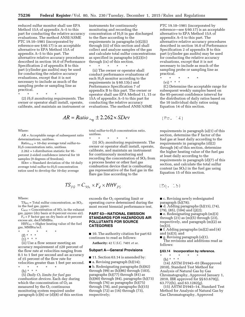
75236 Federal Register / Vol. 80, No. 230 / Tuesday, December 1, 2015 / Rules and Regulations
reduced sulfur monitor shall use EPA Method 15A of appendix A–5 to this part for conducting the relative accuracy evaluations. The method ANSI/ASME PTC 19.10–1981 (incorporated by reference-see § 60.17) is an acceptable alternative to EPA Method 15A of appendix A–5 to this part. The alternative relative accuracy procedures described in section 16.0 of Performance Specification 2 of appendix B to this part (cylinder gas audits) may be used for conducting the relative accuracy evaluations, except that it is not necessary to include as much of the sampling probe or sampling line as practical. * * * * *
(2) H2S monitoring requirements. The owner or operator shall install, operate, calibrate, and maintain an instrument or
instruments for continuously monitoring and recording the concentration of H2S in gas discharged to the flare according to the requirements in paragraphs (e)(2)(i) through (iii) of this section and shall collect and analyze samples of the gas and calculate total sulfur concentrations as specified in paragraphs (e)(2)(iv) through (ix) of this section. * * * * *
(ii) The owner or operator shall conduct performance evaluations of each H2S monitor according to the requirements in § 60.13(c) and Performance Specification 7 of appendix B to this part. The owner or operator shall use EPA Method 11, 15 or 15A of appendix A–5 to this part for conducting the relative accuracy evaluations. The method ANSI/ASME
PTC 19.10–1981 (incorporated by reference—see § 60.17) is an acceptable alternative to EPA Method 15A of appendix A–5 to this part. The alternative relative accuracy procedures described in section 16.0 of Performance Specification 2 of appendix B to this part (cylinder gas audits) may be used for conducting the relative accuracy evaluations, except that it is not necessary to include as much of the sampling probe or sampling line as practical. * * * * *
(vi) * * * (C) Determine the acceptable range for
subsequent weekly samples based on the 95-percent confidence interval for the distribution of daily ratios based on the 10 individual daily ratios using Equation 14 of this section.
Where:
AR = Acceptable range of subsequent ratio determinations, unitless.
RatioAvg = 10-day average total sulfur-to- H2S concentration ratio, unitless.
2.262 = t-distribution statistic for 95- percent 2-sided confidence interval for 10 samples (9 degrees of freedom).
SDev = Standard deviation of the 10 daily average total sulfur-to-H2S concentration ratios used to develop the 10-day average
total sulfur-to-H2S concentration ratio, unitless.
* * * * * (3) SO2 monitoring requirements. The
owner or operator shall install, operate, calibrate, and maintain an instrument for continuously monitoring and recording the concentration of SO2 from a process heater or other fuel gas combustion device that is combusting gas representative of the fuel gas in the flare gas line according to the
requirements in paragraph (a)(1) of this section, determine the F factor of the fuel gas at least daily according to the requirements in paragraphs (d)(2) through (4) of this section, determine the higher heating value of the fuel gas at least daily according to the requirements in paragraph (d)(7) of this section, and calculate the total sulfur content (as SO2) in the fuel gas using Equation 15 of this section.
Where: TSFG = Total sulfur concentration, as SO2,
in the fuel gas, ppmv. CSO2 = Concentration of SO2 in the exhaust
gas, ppmv (dry basis at 0-percent excess air). Fd = F factor gas on dry basis at 0-percent
excess air, dscf/MMBtu. HHVFG = Higher heating value of the fuel
gas, MMBtu/scf.
* * * * * (f) * * * (1) * * * (ii) Use a flow sensor meeting an
accuracy requirement of ±20 percent of the flow rate at velocities ranging from 0.1 to 1 feet per second and an accuracy of ±5 percent of the flow rate for velocities greater than 1 feet per second. * * * * *
(h) * * * (5) Daily O2 limits for fuel gas
combustion devices. Each day during which the concentration of O2 as measured by the O2 continuous monitoring system required under paragraph (c)(6) or (d)(8) of this section
exceeds the O2 operating limit or operating curve determined during the most recent biennial performance test.
PART 63—NATIONAL EMISSION STANDARDS FOR HAZARDOUS AIR POLLUTANTS FOR SOURCE CATEGORIES
■ 10. The authority citation for part 63 continues to read as follows:
Authority: 42 U.S.C. 7401 et se.
Subpart A—General Provisions
■ 11. Section 63.14 is amended by: ■ a. Revising paragraph (h)(14); ■ b. Redesignating paragraphs (h)(82) through (99) as (h)(86) through (103), paragraphs (h)(77) through (81) as (h)(80) through (84), paragraphs (h)(73) through (76) as paragraphs (h)(75) through (78), and paragraphs (h)(15) through (72) as (16) through (73), respectively;
■ c. Revising newly redesignated paragraph (h)(78); ■ d. Adding paragraphs (h)(15), (74), (79), (85), (104) and (j)(2); ■ e. Redesignating paragraph (m)(3) through (21) as (m)(5) through (23), respectively, and paragraph (m)(2) as (m)(3). ■ f. Adding paragraphs (m)(2) and (4) and (n)(3); and ■ g. Revising paragraph (s)(1).
The revisions and additions read as follows:
§ 63.14 Incorporation by reference. * * * * *
(h) * * * (14) ASTM D1945–03 (Reapproved
2010), Standard Test Method for Analysis of Natural Gas by Gas Chromatography, Approved January 1, 2010, IBR approved for §§ 63.670(j), 63.772(h), and 63.1282(g).
(15) ASTM D1945–14, Standard Test Method for Analysis of Natural Gas by Gas Chromatography, Approved
VerDate Sep<11>2014 23:11 Nov 30, 2015 Jkt 238001 PO 00000 Frm 00060 Fmt 4701 Sfmt 4700 E:\FR\FM\01DER2.SGM 01DER2 ER
01D
E15
.006
</G
PH
>E
R01
DE
15.0
07<
/GP
H>
tkel
ley
on D
SK
3SP
TV
N1P
RO
D w
ith R
ULE
S2
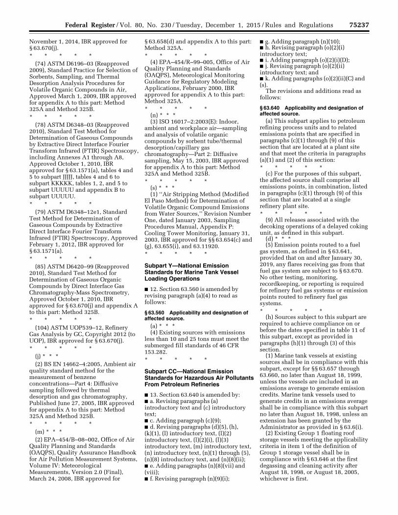
75237 Federal Register / Vol. 80, No. 230 / Tuesday, December 1, 2015 / Rules and Regulations
November 1, 2014, IBR approved for § 63.670(j). * * * * *
(74) ASTM D6196–03 (Reapproved 2009), Standard Practice for Selection of Sorbents, Sampling, and Thermal Desorption Analysis Procedures for Volatile Organic Compounds in Air, Approved March 1, 2009, IBR approved for appendix A to this part: Method 325A and Method 325B. * * * * *
(78) ASTM D6348–03 (Reapproved 2010), Standard Test Method for Determination of Gaseous Compounds by Extractive Direct Interface Fourier Transform Infrared (FTIR) Spectroscopy, including Annexes A1 through A8, Approved October 1, 2010, IBR approved for § 63.1571(a), tables 4 and 5 to subpart JJJJJ, tables 4 and 6 to subpart KKKKK, tables 1, 2, and 5 to subpart UUUUU and appendix B to subpart UUUUU. * * * * *
(79) ASTM D6348–12e1, Standard Test Method for Determination of Gaseous Compounds by Extractive Direct Interface Fourier Transform Infrared (FTIR) Spectroscopy, Approved February 1, 2012, IBR approved for § 63.1571(a). * * * * *
(85) ASTM D6420–99 (Reapproved 2010), Standard Test Method for Determination of Gaseous Organic Compounds by Direct Interface Gas Chromatography-Mass Spectrometry, Approved October 1, 2010, IBR approved for § 63.670(j) and appendix A to this part: Method 325B. * * * * *
(104) ASTM UOP539–12, Refinery Gas Analysis by GC, Copyright 2012 (to UOP), IBR approved for § 63.670(j). * * * * *
(j) * * * (2) BS EN 14662–4:2005, Ambient air
quality standard method for the measurement of benzene concentrations—Part 4: Diffusive sampling followed by thermal desorption and gas chromatography, Published June 27, 2005, IBR approved for appendix A to this part: Method 325A and Method 325B. * * * * *
(m) * * * (2) EPA–454/B–08–002, Office of Air
Quality Planning and Standards (OAQPS), Quality Assurance Handbook for Air Pollution Measurement Systems, Volume IV: Meteorological Measurements, Version 2.0 (Final), March 24, 2008, IBR approved for
§ 63.658(d) and appendix A to this part: Method 325A. * * * * *
(4) EPA–454/R–99–005, Office of Air Quality Planning and Standards (OAQPS), Meteorological Monitoring Guidance for Regulatory Modeling Applications, February 2000, IBR approved for appendix A to this part: Method 325A. * * * * *
(n) * * * (3) ISO 16017–2:2003(E): Indoor,
ambient and workplace air—sampling and analysis of volatile organic compounds by sorbent tube/thermal desorption/capillary gas chromatography—Part 2: Diffusive sampling, May 15, 2003, IBR approved for appendix A to this part: Method 325A and Method 325B. * * * * *
(s) * * * (1) ‘‘Air Stripping Method (Modified
El Paso Method) for Determination of Volatile Organic Compound Emissions from Water Sources,’’ Revision Number One, dated January 2003, Sampling Procedures Manual, Appendix P: Cooling Tower Monitoring, January 31, 2003, IBR approved for §§ 63.654(c) and (g), 63.655(i), and 63.11920. * * * * *
Subpart Y—National Emission Standards for Marine Tank Vessel Loading Operations
■ 12. Section 63.560 is amended by revising paragraph (a)(4) to read as follows:
§ 63.560 Applicability and designation of affected source.
(a) * * * (4) Existing sources with emissions
less than 10 and 25 tons must meet the submerged fill standards of 46 CFR 153.282. * * * * *
Subpart CC—National Emission Standards for Hazardous Air Pollutants From Petroleum Refineries
■ 13. Section 63.640 is amended by: ■ a. Revising paragraphs (a) introductory text and (c) introductory text; ■ c. Adding paragraph (c)(9); ■ d. Revising paragraphs (d)(5), (h), (k)(1), (l) introductory text, (l)(2) introductory text, (l)(2)(i), (l)(3) introductory text, (m) introductory text, (n) introductory text, (n)(1) through (5), (n)(8) introductory text, and (n)(8)(ii); ■ e. Adding paragraphs (n)(8)(vii) and (viii); ■ f. Revising paragraph (n)(9)(i);
■ g. Adding paragraph (n)(10); ■ h. Revising paragraph (o)(2)(i) introductory text; ■ i. Adding paragraph (o)(2)(i)(D); ■ j. Revising paragraph (o)(2)(ii) introductory text; and ■ k. Adding paragraphs (o)(2)(ii)(C) and (s).
The revisions and additions read as follows:
§ 63.640 Applicability and designation of affected source.
(a) This subpart applies to petroleum refining process units and to related emissions points that are specified in paragraphs (c)(1) through (9) of this section that are located at a plant site and that meet the criteria in paragraphs (a)(1) and (2) of this section: * * * * *
(c) For the purposes of this subpart, the affected source shall comprise all emissions points, in combination, listed in paragraphs (c)(1) through (9) of this section that are located at a single refinery plant site. * * * * *
(9) All releases associated with the decoking operations of a delayed coking unit, as defined in this subpart.
(d) * * * (5) Emission points routed to a fuel
gas system, as defined in § 63.641, provided that on and after January 30, 2019, any flares receiving gas from that fuel gas system are subject to § 63.670. No other testing, monitoring, recordkeeping, or reporting is required for refinery fuel gas systems or emission points routed to refinery fuel gas systems. * * * * *
(h) Sources subject to this subpart are required to achieve compliance on or before the dates specified in table 11 of this subpart, except as provided in paragraphs (h)(1) through (3) of this section.
(1) Marine tank vessels at existing sources shall be in compliance with this subpart, except for §§ 63.657 through 63.660, no later than August 18, 1999, unless the vessels are included in an emissions average to generate emission credits. Marine tank vessels used to generate credits in an emissions average shall be in compliance with this subpart no later than August 18, 1998, unless an extension has been granted by the Administrator as provided in § 63.6(i).
(2) Existing Group 1 floating roof storage vessels meeting the applicability criteria in item 1 of the definition of Group 1 storage vessel shall be in compliance with § 63.646 at the first degassing and cleaning activity after August 18, 1998, or August 18, 2005, whichever is first.
VerDate Sep<11>2014 23:11 Nov 30, 2015 Jkt 238001 PO 00000 Frm 00061 Fmt 4701 Sfmt 4700 E:\FR\FM\01DER2.SGM 01DER2tkel
ley
on D
SK
3SP
TV
N1P
RO
D w
ith R
ULE
S2
75238 Federal Register / Vol. 80, No. 230 / Tuesday, December 1, 2015 / Rules and Regulations
(3) An owner or operator may elect to comply with the provisions of § 63.648(c) through (i) as an alternative to the provisions of § 63.648(a) and (b). In such cases, the owner or operator shall comply no later than the dates specified in paragraphs (h)(3)(i) through (iii) of this section.
(i) Phase I (see table 2 of this subpart), beginning on August 18, 1998;
(ii) Phase II (see table 2 of this subpart), beginning no later than August 18, 1999; and
(iii) Phase III (see table 2 of this subpart), beginning no later than February 18, 2001. * * * * *
(k) * * * (1) The reconstructed source,
addition, or change shall be in compliance with the new source requirements in item (1), (2), or (3) of table 11 of this subpart, as applicable, upon initial startup of the reconstructed source or by August 18, 1995, whichever is later; and * * * * *
(l) If an additional petroleum refining process unit is added to a plant site or if a miscellaneous process vent, storage vessel, gasoline loading rack, marine tank vessel loading operation, heat exchange system, or decoking operation that meets the criteria in paragraphs (c)(1) through (9) of this section is added to an existing petroleum refinery or if another deliberate operational process change creating an additional Group 1 emissions point(s) (as defined in § 63.641) is made to an existing petroleum refining process unit, and if the addition or process change is not subject to the new source requirements as determined according to paragraph (i) or (j) of this section, the requirements in paragraphs (l)(1) through (4) of this section shall apply. Examples of process changes include, but are not limited to, changes in production capacity, or feed or raw material where the change requires construction or physical alteration of the existing equipment or catalyst type, or whenever there is replacement, removal, or addition of recovery equipment. For purposes of this paragraph (l) and paragraph (m) of this section, process changes do not include: Process upsets, unintentional temporary process changes, and changes that are within the equipment configuration and operating conditions documented in the Notification of Compliance Status report required by § 63.655(f). * * * * *
(2) The added emission point(s) and any emission point(s) within the added or changed petroleum refining process
unit shall be in compliance with the applicable requirements in item (4) of table 11 of this subpart by the dates specified in paragraph (l)(2)(i) or (ii) of this section.
(i) If a petroleum refining process unit is added to a plant site or an emission point(s) is added to any existing petroleum refining process unit, the added emission point(s) shall be in compliance upon initial startup of any added petroleum refining process unit or emission point(s) or by the applicable compliance date in item (4) of table 11 of this subpart, whichever is later. * * * * *
(3) The owner or operator of a petroleum refining process unit or of a storage vessel, miscellaneous process vent, wastewater stream, gasoline loading rack, marine tank vessel loading operation, heat exchange system, or decoking operation meeting the criteria in paragraphs (c)(1) through (9) of this section that is added to a plant site and is subject to the requirements for existing sources shall comply with the reporting and recordkeeping requirements that are applicable to existing sources including, but not limited to, the reports listed in paragraphs (l)(3)(i) through (vii) of this section. A process change to an existing petroleum refining process unit shall be subject to the reporting requirements for existing sources including, but not limited to, the reports listed in paragraphs (l)(3)(i) through (vii) of this section. The applicable reports include, but are not limited to: * * * * *
(m) If a change that does not meet the criteria in paragraph (l) of this section is made to a petroleum refining process unit subject to this subpart, and the change causes a Group 2 emission point to become a Group 1 emission point (as defined in § 63.641), then the owner or operator shall comply with the applicable requirements of this subpart for existing sources, as specified in item (4) of table 11 of this subpart, for the Group 1 emission point as expeditiously as practicable, but in no event later than 3 years after the emission point becomes Group 1. * * * * *
(n) Overlap of this subpart with other regulations for storage vessels. As applicable, paragraphs (n)(1), (3), (4), (6), and (7) of this section apply for Group 2 storage vessels and paragraphs (n)(2) and (5) of this section apply for Group 1 storage vessels.
(1) After the compliance dates specified in paragraph (h) of this section, a Group 2 storage vessel that is subject to the provisions of 40 CFR part
60, subpart Kb, is required to comply only with the requirements of 40 CFR part 60, subpart Kb, except as provided in paragraph (n)(8) of this section. After the compliance dates specified in paragraph (h) of this section, a Group 2 storage vessel that is subject to the provisions of 40 CFR part 61, subpart Y, is required to comply only with the requirements of 40 CFR part 61, subpart Y, except as provided in paragraph (n)(10) of this section.
(2) After the compliance dates specified in paragraph (h) of this section, a Group 1 storage vessel that is also subject to 40 CFR part 60, subpart Kb, is required to comply only with either 40 CFR part 60, subpart Kb, except as provided in paragraph (n)(8) of this section or this subpart. After the compliance dates specified in paragraph (h) of this section, a Group 1 storage vessel that is also subject to 40 CFR part 61, subpart Y, is required to comply only with either 40 CFR part 61, subpart Y, except as provided in paragraph (n)(10) of this section or this subpart.
(3) After the compliance dates specified in paragraph (h) of this section, a Group 2 storage vessel that is part of a new source and is subject to 40 CFR 60.110b, but is not required to apply controls by 40 CFR 60.110b or 60.112b, is required to comply only with this subpart.
(4) After the compliance dates specified in paragraph (h) of this section, a Group 2 storage vessel that is part of a new source and is subject to 40 CFR 61.270, but is not required to apply controls by 40 CFR 61.271, is required to comply only with this subpart.
(5) After the compliance dates specified in paragraph (h) of this section, a Group 1 storage vessel that is also subject to the provisions of 40 CFR part 60, subpart K or Ka, is required to only comply with the provisions of this subpart. * * * * *
(8) Storage vessels described by paragraph (n)(1) of this section are to comply with 40 CFR part 60, subpart Kb, except as provided in paragraphs (n)(8)(i) through (vi) of this section. Storage vessels described by paragraph (n)(2) electing to comply with part 60, subpart Kb of this chapter shall comply with subpart Kb except as provided in paragraphs (n)(8)(i) through (viii) of this section. * * * * *
(ii) If the owner or operator determines that it is unsafe to perform the seal gap measurements required in § 60.113b(b) of this chapter or to inspect the vessel to determine compliance with
VerDate Sep<11>2014 23:11 Nov 30, 2015 Jkt 238001 PO 00000 Frm 00062 Fmt 4701 Sfmt 4700 E:\FR\FM\01DER2.SGM 01DER2tkel
ley
on D
SK
3SP
TV
N1P
RO
D w
ith R
ULE
S2
75239 Federal Register / Vol. 80, No. 230 / Tuesday, December 1, 2015 / Rules and Regulations
§ 60.113b(a) of this chapter because the roof appears to be structurally unsound and poses an imminent danger to inspecting personnel, the owner or operator shall comply with the requirements in either § 63.120(b)(7)(i) or (ii) of subpart G (only up to the compliance date specified in paragraph (h) of this section for compliance with § 63.660, as applicable) or either § 63.1063(c)(2)(iv)(A) or (B) of subpart WW. * * * * *
(vii) To be in compliance with § 60.112b(a)(1)(iv) or (a)(2)(ii) of this chapter, guidepoles in floating roof storage vessels must be equipped with covers and/or controls (e.g., pole float system, pole sleeve system, internal sleeve system or flexible enclosure system) as appropriate to comply with the ‘‘no visible gap’’ requirement.
(viii) If a flare is used as a control device for a storage vessel, on and after January 30, 2019, the owner or operator must meet the requirements of § 63.670 instead of the requirements referenced from part 60, subpart Kb of this chapter for that flare.
(9) * * * (i) If the owner or operator determines
that it is unsafe to perform the seal gap measurements required in § 60.113a(a)(1) of this chapter because the floating roof appears to be structurally unsound and poses an imminent danger to inspecting personnel, the owner or operator shall comply with the requirements in either § 63.120(b)(7)(i) or (ii) of subpart G (only up to the compliance date specified in paragraph (h) of this section for compliance with § 63.660, as applicable) or either § 63.1063(c)(2)(iv)(A) or (B) of subpart WW. * * * * *
(10) Storage vessels described by paragraph (n)(1) of this section are to comply with 40 CFR part 61, subpart Y, except as provided in paragraphs (n)(10)(i) through (vi) of this section. Storage vessels described by paragraph (n)(2) electing to comply with 40 CFR part 61, subpart Y, shall comply with subpart Y except as provided for in paragraphs (n)(10)(i) through (viii) of this section.
(i) Storage vessels that are to comply with § 61.271(b) of this chapter are exempt from the secondary seal requirements of § 61.271(b)(2)(ii) of this chapter during the gap measurements for the primary seal required by § 61.272(b) of this chapter.
(ii) If the owner or operator determines that it is unsafe to perform the seal gap measurements required in § 61.272(b) of this chapter or to inspect
the vessel to determine compliance with § 61.272(a) of this chapter because the roof appears to be structurally unsound and poses an imminent danger to inspecting personnel, the owner or operator shall comply with the requirements in either § 63.120(b)(7)(i) or (ii) of subpart G (only up to the compliance date specified in paragraph (h) of this section for compliance with § 63.660, as applicable) or either § 63.1063(c)(2)(iv)(A) or (B) of subpart WW.
(iii) If a failure is detected during the inspections required by § 61.272(a)(2) of this chapter or during the seal gap measurements required by § 61.272(b)(1) of this chapter, and the vessel cannot be repaired within 45 days and the vessel cannot be emptied within 45 days, the owner or operator may utilize up to two extensions of up to 30 additional calendar days each. The owner or operator is not required to provide a request for the extension to the Administrator.
(iv) If an extension is utilized in accordance with paragraph (n)(10)(iii) of this section, the owner or operator shall, in the next periodic report, identify the vessel, provide the information listed in § 61.272(a)(2) or (b)(4)(iii) of this chapter, and describe the nature and date of the repair made or provide the date the storage vessel was emptied.
(v) Owners and operators of storage vessels complying with 40 CFR part 61, subpart Y, may submit the inspection reports required by § 61.275(a), (b)(1), and (d) of this chapter as part of the periodic reports required by this subpart, rather than within the 60-day period specified in § 61.275(a), (b)(1), and (d) of this chapter.
(vi) The reports of rim seal inspections specified in § 61.275(d) of this chapter are not required if none of the measured gaps or calculated gap areas exceed the limitations specified in § 61.272(b)(4) of this chapter. Documentation of the inspections shall be recorded as specified in § 61.276(a) of this chapter.
(vii) To be in compliance with § 61.271(a)(6) or (b)(3) of this chapter, guidepoles in floating roof storage vessels must be equipped with covers and/or controls (e.g., pole float system, pole sleeve system, internal sleeve system or flexible enclosure system) as appropriate to comply with the ‘‘no visible gap’’ requirement.
(viii) If a flare is used as a control device for a storage vessel, on and after January 30, 2019, the owner or operator must meet the requirements of § 63.670 instead of the requirements referenced from part 61, subpart Y of this chapter for that flare.
(o) * * * (2) * * * (i) Comply with paragraphs
(o)(2)(i)(A) through (D) of this section. * * * * *
(D) If a flare is used as a control device, on and after January 30, 2019, the flare shall meet the requirements of § 63.670. Prior to January 30, 2019, the flare shall meet the applicable requirements of 40 CFR part 61, subpart FF, and subpart G of this part, or the requirements of § 63.670.
(ii) Comply with paragraphs (o)(2)(ii)(A) through (C) of this section. * * * * *
(C) If a flare is used as a control device, on and after January 30, 2019, the flare shall meet the requirements of § 63.670. Prior to January 30, 2019, the flare shall meet the applicable requirements of 40 CFR part 61, subpart FF, and subpart G of this part, or the requirements of § 63.670. * * * * *
(s) Overlap of this subpart with other regulation for flares. On January 30, 2019, flares that are subject to the provisions of 40 CFR 60.18 or 63.11 and subject to this subpart are required to comply only with the provisions specified in this subpart. Prior to January 30, 2019, flares that are subject to the provisions of 40 CFR 60.18 or 63.11 and elect to comply with the requirements in §§ 63.670 and 63.671 are required to comply only with the provisions specified in this subpart. ■ 14. Section 63.641 is amended by: ■ a. Adding, in alphabetical order, definitions of ‘‘Assist air,’’ ‘‘Assist steam,’’ ‘‘Center steam,’’ ‘‘Closed blowdown system,’’ ‘‘Combustion zone,’’ ‘‘Combustion zone gas,’’ ‘‘Decoking operations,’’ ‘‘Delayed coking unit,’’ ‘‘Flare,’’ ‘‘Flare purge gas,’’ ‘‘Flare supplemental gas,’’ ‘‘Flare sweep gas,’’ ‘‘Flare vent gas,’’ ‘‘Flexible enclosure device,’’ ‘‘Force majeure event,’’ ‘‘Lower steam,’’ ‘‘Net heating value,’’ ‘‘Perimeter assist air,’’ ‘‘Pilot gas,’’ ‘‘Premix assist air,’’ ‘‘Regulated material,’’ ‘‘Thermal expansion relief valve,’’ ‘‘Total steam,’’ and ‘‘Upper steam’’; and ■ b. Revising the definitions of ‘‘Delayed coker vent,’’ ‘‘Emission point,’’ ‘‘Group 1 storage vessel,’’ ‘‘Miscellaneous process vent,’’ ‘‘Periodically discharged,’’ and ‘‘Reference control technology for storage vessels.’’
The revisions and additions read as follows:
§ 63.641 Definitions.
* * * * * Assist air means all air that
intentionally is introduced prior to or at
VerDate Sep<11>2014 23:11 Nov 30, 2015 Jkt 238001 PO 00000 Frm 00063 Fmt 4701 Sfmt 4700 E:\FR\FM\01DER2.SGM 01DER2tkel
ley
on D
SK
3SP
TV
N1P
RO
D w
ith R
ULE
S2
75240 Federal Register / Vol. 80, No. 230 / Tuesday, December 1, 2015 / Rules and Regulations
a flare tip through nozzles or other hardware conveyance for the purposes including, but not limited to, protecting the design of the flare tip, promoting turbulence for mixing or inducing air into the flame. Assist air includes premix assist air and perimeter assist air. Assist air does not include the surrounding ambient air.
Assist steam means all steam that intentionally is introduced prior to or at a flare tip through nozzles or other hardware conveyance for the purposes including, but not limited to, protecting the design of the flare tip, promoting turbulence for mixing or inducing air into the flame. Assist steam includes, but is not necessarily limited to, center steam, lower steam and upper steam. * * * * *
Center steam means the portion of assist steam introduced into the stack of a flare to reduce burnback.
Closed blowdown system means a system used for depressuring process vessels that is not open to the atmosphere and is configured of piping, ductwork, connections, accumulators/knockout drums, and, if necessary, flow inducing devices that transport gas or vapor from process vessel to a control device or back into the process. * * * * *
Combustion zone means the area of the flare flame where the combustion zone gas combines for combustion.
Combustion zone gas means all gases and vapors found just after a flare tip. This gas includes all flare vent gas, total steam, and premix air. * * * * *
Decoking operations means the sequence of steps conducted at the end of the delayed coking unit’s cooling cycle to open the coke drum to the atmosphere in order to remove coke from the coke drum. Decoking operations begin at the end of the cooling cycle when steam released from the coke drum is no longer discharged via the unit’s blowdown system but instead is vented directly to the atmosphere. Decoking operations include atmospheric depressuring (venting), deheading, draining, and decoking (coke cutting).
Delayed coker vent means a miscellaneous process vent that contains uncondensed vapors from the delayed coking unit’s blowdown system. Venting from the delayed coker vent is typically intermittent in nature, and occurs primarily during the cooling cycle of a delayed coking unit coke drum when vapor from the coke drums cannot be sent to the fractionator column for product recovery. The emissions from the decoking operations,
which include direct atmospheric venting, deheading, draining, or decoking (coke cutting), are not considered to be delayed coker vents.
Delayed coking unit means a refinery process unit in which high molecular weight petroleum derivatives are thermally cracked and petroleum coke is produced in a series of closed, batch system reactors. A delayed coking unit includes, but is not limited to, all of the coke drums associated with a single fractionator; the fractionator, including the bottoms receiver and the overhead condenser; the coke drum cutting water and quench system, including the jet pump and coker quench water tank; and the coke drum blowdown recovery compressor system. * * * * *
Emission point means an individual miscellaneous process vent, storage vessel, wastewater stream, equipment leak, decoking operation or heat exchange system associated with a petroleum refining process unit; an individual storage vessel or equipment leak associated with a bulk gasoline terminal or pipeline breakout station classified under Standard Industrial Classification code 2911; a gasoline loading rack classified under Standard Industrial Classification code 2911; or a marine tank vessel loading operation located at a petroleum refinery. * * * * *
Flare means a combustion device lacking an enclosed combustion chamber that uses an uncontrolled volume of ambient air to burn gases. For the purposes of this rule, the definition of flare includes, but is not necessarily limited to, air-assisted flares, steam- assisted flares and non-assisted flares.
Flare purge gas means gas introduced between a flare header’s water seal and the flare tip to prevent oxygen infiltration (backflow) into the flare tip. For a flare with no water seal, the function of flare purge gas is performed by flare sweep gas and, therefore, by definition, such a flare has no flare purge gas.
Flare supplemental gas means all gas introduced to the flare in order to improve the combustible characteristics of combustion zone gas.
Flare sweep gas means, for a flare with a flare gas recovery system, the gas intentionally introduced into the flare header system to maintain a constant flow of gas through the flare header in order to prevent oxygen buildup in the flare header; flare sweep gas in these flares is introduced prior to and recovered by the flare gas recovery system. For a flare without a flare gas recovery system, flare sweep gas means
the gas intentionally introduced into the flare header system to maintain a constant flow of gas through the flare header and out the flare tip in order to prevent oxygen buildup in the flare header and to prevent oxygen infiltration (backflow) into the flare tip.
Flare vent gas means all gas found just prior to the flare tip. This gas includes all flare waste gas (i.e., gas from facility operations that is directed to a flare for the purpose of disposing of the gas), that portion of flare sweep gas that is not recovered, flare purge gas and flare supplemental gas, but does not include pilot gas, total steam or assist air.
Flexible enclosure device means a seal made of an elastomeric fabric (or other material) which completely encloses a slotted guidepole or ladder and eliminates the vapor emission pathway from inside the storage vessel through the guidepole slots or ladder slots to the outside air. * * * * *
Force majeure event means a release of HAP, either directly to the atmosphere from a relief valve or discharged via a flare, that is demonstrated to the satisfaction of the Administrator to result from an event beyond the refinery owner or operator’s control, such as natural disasters; acts of war or terrorism; loss of a utility external to the refinery (e.g., external power curtailment), excluding power curtailment due to an interruptible service agreement; and fire or explosion originating at a near or adjoining facility outside of the refinery owner or operator’s control that impacts the refinery’s ability to operate. * * * * *
Group 1 storage vessel means: (1) Prior to February 1, 2016: (i) A storage vessel at an existing
source that has a design capacity greater than or equal to 177 cubic meters and stored-liquid maximum true vapor pressure greater than or equal to 10.4 kilopascals and stored-liquid annual average true vapor pressure greater than or equal to 8.3 kilopascals and annual average HAP liquid concentration greater than 4 percent by weight total organic HAP;
(ii) A storage vessel at a new source that has a design storage capacity greater than or equal to 151 cubic meters and stored-liquid maximum true vapor pressure greater than or equal to 3.4 kilopascals and annual average HAP liquid concentration greater than 2 percent by weight total organic HAP; or
(iii) A storage vessel at a new source that has a design storage capacity greater than or equal to 76 cubic meters and less than 151 cubic meters and stored-
VerDate Sep<11>2014 23:11 Nov 30, 2015 Jkt 238001 PO 00000 Frm 00064 Fmt 4701 Sfmt 4700 E:\FR\FM\01DER2.SGM 01DER2tkel
ley
on D
SK
3SP
TV
N1P
RO
D w
ith R
ULE
S2
75241 Federal Register / Vol. 80, No. 230 / Tuesday, December 1, 2015 / Rules and Regulations
liquid maximum true vapor pressure greater than or equal to 77 kilopascals and annual average HAP liquid concentration greater than 2 percent by weight total organic HAP.
(2) On and after February 1, 2016: (i) A storage vessel at an existing
source that has a design capacity greater than or equal to 151 cubic meters (40,000 gallons) and stored-liquid maximum true vapor pressure greater than or equal to 5.2 kilopascals (0.75 pounds per square inch) and annual average HAP liquid concentration greater than 4 percent by weight total organic HAP;
(ii) A storage vessel at an existing source that has a design storage capacity greater than or equal to 76 cubic meters (20,000 gallons) and less than 151 cubic meters (40,000 gallons) and stored- liquid maximum true vapor pressure greater than or equal to 13.1 kilopascals (1.9 pounds per square inch) and annual average HAP liquid concentration greater than 4 percent by weight total organic HAP;
(iii) A storage vessel at a new source that has a design storage capacity greater than or equal to 151 cubic meters (40,000 gallons) and stored-liquid maximum true vapor pressure greater than or equal to 3.4 kilopascals (0.5 pounds per square inch) and annual average HAP liquid concentration greater than 2 percent by weight total organic HAP; or
(iv) A storage vessel at a new source that has a design storage capacity greater than or equal to 76 cubic meters (20,000 gallons) and less than 151 cubic meters (40,000 gallons) and stored-liquid maximum true vapor pressure greater than or equal to 13.1 kilopascals (1.9 pounds per square inch) and annual average HAP liquid concentration greater than 2 percent by weight total organic HAP. * * * * *
Lower steam means the portion of assist steam piped to an exterior annular ring near the lower part of a flare tip, which then flows through tubes to the flare tip, and ultimately exits the tubes at the flare tip. * * * * *
Miscellaneous process vent means a gas stream containing greater than 20 parts per million by volume organic HAP that is continuously or periodically discharged from a petroleum refining process unit meeting the criteria specified in § 63.640(a). Miscellaneous process vents include gas streams that are discharged directly to the atmosphere, gas streams that are routed to a control device prior to discharge to the atmosphere, or gas streams that are
diverted through a product recovery device prior to control or discharge to the atmosphere. Miscellaneous process vents include vent streams from: Caustic wash accumulators, distillation tower condensers/accumulators, flash/knockout drums, reactor vessels, scrubber overheads, stripper overheads, vacuum pumps, steam ejectors, hot wells, high point bleeds, wash tower overheads, water wash accumulators, blowdown condensers/accumulators, and delayed coker vents. Miscellaneous process vents do not include:
(1) Gaseous streams routed to a fuel gas system, provided that on and after January 30, 2019, any flares receiving gas from the fuel gas system are in compliance with § 63.670;
(2) Pressure relief device discharges; (3) Leaks from equipment regulated
under § 63.648; (4) [Reserved] (5) In situ sampling systems (onstream
analyzers) until January 30, 2019. After this date, these sampling systems will be included in the definition of miscellaneous process vents;
(6) Catalytic cracking unit catalyst regeneration vents;
(7) Catalytic reformer regeneration vents;
(8) Sulfur plant vents; (9) Vents from control devices such as
scrubbers, boilers, incinerators, and electrostatic precipitators applied to catalytic cracking unit catalyst regeneration vents, catalytic reformer regeneration vents, and sulfur plant vents;
(10) Vents from any stripping operations applied to comply with the wastewater provisions of this subpart, subpart G of this part, or 40 CFR part 61, subpart FF;
(11) Emissions associated with delayed coking unit decoking operations;
(12) Vents from storage vessels; (13) Emissions from wastewater
collection and conveyance systems including, but not limited to, wastewater drains, sewer vents, and sump drains; and
(14) Hydrogen production plant vents through which carbon dioxide is removed from process streams or through which steam condensate produced or treated within the hydrogen plant is degassed or deaerated.
Net heating value means the energy released as heat when a compound undergoes complete combustion with oxygen to form gaseous carbon dioxide and gaseous water (also referred to as lower heating value). * * * * *
Perimeter assist air means the portion of assist air introduced at the perimeter
of the flare tip or above the flare tip. Perimeter assist air includes air intentionally entrained in lower and upper steam. Perimeter assist air includes all assist air except premix assist air.
Periodically discharged means discharges that are intermittent and associated with routine operations, maintenance activities, startups, shutdowns, malfunctions, or process upsets. * * * * *
Pilot gas means gas introduced into a flare tip that provides a flame to ignite the flare vent gas. * * * * *
Premix assist air means the portion of assist air that is introduced to the flare vent gas, whether injected or induced, prior to the flare tip. Premix assist air also includes any air intentionally entrained in center steam. * * * * *
Reference control technology for storage vessels means either:
(1) For Group 1 storage vessels complying with § 63.660:
(i) An internal floating roof, including an external floating roof converted to an internal floating roof, meeting the specifications of § 63.1063(a)(1)(i) and (b);
(ii) An external floating roof meeting the specifications of § 63.1063(a)(1)(ii), (a)(2), and (b); or
(iii) [Reserved] (iv) A closed-vent system to a control
device that reduces organic HAP emissions by 95 percent, or to an outlet concentration of 20 parts per million by volume (ppmv).
(v) For purposes of emissions averaging, these four technologies are considered equivalent.
(2) For all other storage vessels: (i) An internal floating roof meeting
the specifications of § 63.119(b) of subpart G except for § 63.119(b)(5) and (6);
(ii) An external floating roof meeting the specifications of § 63.119(c) of subpart G except for § 63.119(c)(2);
(iii) An external floating roof converted to an internal floating roof meeting the specifications of § 63.119(d) of subpart G except for § 63.119(d)(2); or
(iv) A closed-vent system to a control device that reduces organic HAP emissions by 95 percent, or to an outlet concentration of 20 parts per million by volume.
(v) For purposes of emissions averaging, these four technologies are considered equivalent. * * * * *
Regulated material means any stream associated with emission sources listed
VerDate Sep<11>2014 23:11 Nov 30, 2015 Jkt 238001 PO 00000 Frm 00065 Fmt 4701 Sfmt 4700 E:\FR\FM\01DER2.SGM 01DER2tkel
ley
on D
SK
3SP
TV
N1P
RO
D w
ith R
ULE
S2

75242 Federal Register / Vol. 80, No. 230 / Tuesday, December 1, 2015 / Rules and Regulations
in § 63.640(c) required to meet control requirements under this subpart as well as any stream for which this subpart or a cross-referencing subpart specifies that the requirements for flare control devices in § 63.670 must be met. * * * * *
Thermal expansion relief valve means a pressure relief valve designed to protect equipment from excess pressure due to thermal expansion of blocked liquid-filled equipment or piping due to ambient heating or heat from a heat tracing system. Pressure relief valves designed to protect equipment from excess pressure due to blockage against a pump or compressor or due to fire contingency are not thermal expansion relief valves. * * * * *
Total steam means the total of all steam that is supplied to a flare and includes, but is not limited to, lower steam, center steam and upper steam.
Upper steam means the portion of assist steam introduced via nozzles located on the exterior perimeter of the upper end of the flare tip. * * * * * ■ 15. Section 63.642 is amended by: ■ a. Adding paragraph (b); ■ b. Revising paragraphs (d)(3), (e), (i), (k) introductory text, (k)(1), (l) introductory text, and (l)(2); and ■ c. Adding paragraph (n).
The revisions and additions read as follows:
§ 63.642 General standards.
* * * * * (b) The emission standards set forth in
this subpart shall apply at all times. * * * * *
(d) * * * (3) Performance tests shall be
conducted according to the provisions of § 63.7(e) except that performance tests shall be conducted at maximum representative operating capacity for the process. During the performance test, an owner or operator shall operate the control device at either maximum or minimum representative operating conditions for monitored control device parameters, whichever results in lower emission reduction. An owner or operator shall not conduct a performance test during startup, shutdown, periods when the control device is bypassed or periods when the process, monitoring equipment or control device is not operating properly. The owner/operator may not conduct performance tests during periods of malfunction. The owner or operator must record the process information that is necessary to document operating conditions during the test and include
in such record an explanation to support that the test was conducted at maximum representative operating capacity. Upon request, the owner or operator shall make available to the Administrator such records as may be necessary to determine the conditions of performance tests. * * * * *
(e) All applicable records shall be maintained as specified in § 63.655(i). * * * * *
(i) The owner or operator of an existing source shall demonstrate compliance with the emission standard in paragraph (g) of this section by following the procedures specified in paragraph (k) of this section for all emission points, or by following the emissions averaging compliance approach specified in paragraph (l) of this section for specified emission points and the procedures specified in paragraph (k)(1) of this section. * * * * *
(k) The owner or operator of an existing source may comply, and the owner or operator of a new source shall comply, with the applicable provisions in §§ 63.643 through 63.645, 63.646 or 63.660, 63.647, 63.650, and 63.651, as specified in § 63.640(h).
(1) The owner or operator using this compliance approach shall also comply with the requirements of §§ 63.648 and/ or 63.649, 63.654, 63.655, 63.657, 63.658, 63.670 and 63.671, as applicable. * * * * *
(l) The owner or operator of an existing source may elect to control some of the emission points within the source to different levels than specified under §§ 63.643 through 63.645, 63.646 or 63.660, 63.647, 63.650, and 63.651, as applicable according to § 63.640(h), by using an emissions averaging compliance approach as long as the overall emissions for the source do not exceed the emission level specified in paragraph (g) of this section. The owner or operator using emissions averaging shall meet the requirements in paragraphs (l)(1) and (2) of this section. * * * * *
(2) Comply with the requirements of §§ 63.648 and/or 63.649, 63.654, 63.652, 63.653, 63.655, 63.657, 63.658, 63.670 and 63.671, as applicable. * * * * *
(n) At all times, the owner or operator must operate and maintain any affected source, including associated air pollution control equipment and monitoring equipment, in a manner consistent with safety and good air pollution control practices for
minimizing emissions. The general duty to minimize emissions does not require the owner operator to make any further efforts to reduce emissions if levels required by the applicable standard have been achieved. Determination of whether a source is operating in compliance with operation and maintenance requirements will be based on information available to the Administrator which may include, but is not limited to, monitoring results, review of operation and maintenance procedures, review of operation and maintenance records, and inspection of the source. ■ 16. Section 63.643 is amended by revising paragraphs (a) introductory text and (a)(1) and adding paragraph (c) to read as follows:
§ 63.643 Miscellaneous process vent provisions.
(a) The owner or operator of a Group 1 miscellaneous process vent as defined in § 63.641 shall comply with the requirements of either paragraph (a)(1) or (2) of this section or, if applicable, paragraph (c) of this section. The owner or operator of a miscellaneous process vent that meets the conditions in paragraph (c) of this section is only required to comply with the requirements of paragraph (c) of this section and § 63.655(g)(13) and (i)(12) for that vent.
(1) Reduce emissions of organic HAP’s using a flare. On and after January 30, 2019, the flare shall meet the requirements of § 63.670. Prior to January 30, 2019, the flare shall meet the requirements of § 63.11(b) of subpart A or the requirements of § 63.670. * * * * *
(c) An owner or operator may designate a process vent as a maintenance vent if the vent is only used as a result of startup, shutdown, maintenance, or inspection of equipment where equipment is emptied, depressurized, degassed or placed into service. The owner of operator does not need to designate a maintenance vent as a Group 1 or Group 2 miscellaneous process vent. The owner or operator must comply with the applicable requirements in paragraphs (c)(1) through (3) of this section for each maintenance vent.
(1) Prior to venting to the atmosphere, process liquids are removed from the equipment as much as practical and the equipment is depressured to a control device, fuel gas system, or back to the process until one of the following conditions, as applicable, is met.
(i) The vapor in the equipment served by the maintenance vent has a lower
VerDate Sep<11>2014 23:11 Nov 30, 2015 Jkt 238001 PO 00000 Frm 00066 Fmt 4701 Sfmt 4700 E:\FR\FM\01DER2.SGM 01DER2tkel
ley
on D
SK
3SP
TV
N1P
RO
D w
ith R
ULE
S2
75243 Federal Register / Vol. 80, No. 230 / Tuesday, December 1, 2015 / Rules and Regulations
explosive limit (LEL) of less than 10 percent.
(ii) If there is no ability to measure the LEL of the vapor in the equipment based on the design of the equipment, the pressure in the equipment served by the maintenance vent is reduced to 5 psig or less. Upon opening the maintenance vent, active purging of the equipment cannot be used until the LEL of the vapors in the maintenance vent (or inside the equipment if the maintenance is a hatch or similar type of opening) equipment is less than 10 percent.
(iii) The equipment served by the maintenance vent contains less than 72 pounds of VOC.
(iv) If the maintenance vent is associated with equipment containing pyrophoric catalyst (e.g., hydrotreaters and hydrocrackers) at refineries that do not have a pure hydrogen supply, the LEL of the vapor in the equipment must be less than 20 percent, except for one event per year not to exceed 35 percent.
(2) Except for maintenance vents complying with the alternative in paragraph (c)(1)(iii) of this section, the owner or operator must determine the LEL or, if applicable, equipment pressure using process instrumentation or portable measurement devices and follow procedures for calibration and maintenance according to manufacturer’s specifications.
(3) For maintenance vents complying with the alternative in paragraph (c)(1)(iii) of this section, the owner or operator shall determine mass of VOC in the equipment served by the maintenance vent based on the equipment size and contents after considering any contents drained or purged from the equipment. Equipment size may be determined from equipment design specifications. Equipment contents may be determined using process knowledge. ■ 17. Section 63.644 is amended by revising paragraphs (a) introductory text, (a)(2), and (c) to read as follows:
§ 63.644 Monitoring provisions for miscellaneous process vents.
(a) Except as provided in paragraph (b) of this section, each owner or operator of a Group 1 miscellaneous process vent that uses a combustion device to comply with the requirements in § 63.643(a) shall install the monitoring equipment specified in paragraph (a)(1), (2), (3), or (4) of this section, depending on the type of combustion device used. All monitoring equipment shall be installed, calibrated, maintained, and operated according to manufacturer’s specifications or other written procedures that provide adequate assurance that the equipment
will monitor accurately and, except for CPMS installed for pilot flame monitoring, must meet the applicable minimum accuracy, calibration and quality control requirements specified in table 13 of this subpart. * * * * *
(2) Where a flare is used prior to January 30, 2019, a device (including but not limited to a thermocouple, an ultraviolet beam sensor, or an infrared sensor) capable of continuously detecting the presence of a pilot flame is required, or the requirements of § 63.670 shall be met. Where a flare is used on and after January 30, 2019, the requirements of § 63.670 shall be met. * * * * *
(c) The owner or operator of a Group 1 miscellaneous process vent using a vent system that contains bypass lines that could divert a vent stream away from the control device used to comply with paragraph (a) of this section either directly to the atmosphere or to a control device that does not comply with the requirements in § 63.643(a) shall comply with either paragraph (c)(1) or (2) of this section. Use of the bypass at any time to divert a Group 1 miscellaneous process vent stream to the atmosphere or to a control device that does not comply with the requirements in § 63.643(a) is an emissions standards violation. Equipment such as low leg drains and equipment subject to § 63.648 are not subject to this paragraph (c).
(1) Install, calibrate and maintain a flow indicator that determines whether a vent stream flow is present at least once every hour. A manual block valve equipped with a valve position indicator may be used in lieu of a flow indicator, as long as the valve position indicator is monitored continuously. Records shall be generated as specified in § 63.655(h) and (i). The flow indicator shall be installed at the entrance to any bypass line that could divert the vent stream away from the control device to the atmosphere; or
(2) Secure the bypass line valve in the non-diverting position with a car-seal or a lock-and-key type configuration. A visual inspection of the seal or closure mechanism shall be performed at least once every month to ensure that the valve is maintained in the non-diverting position and that the vent stream is not diverted through the bypass line. * * * * *
■ 18. Section 63.645 is amended by revising paragraphs (e)(1) and (f)(2) to read as follows:
§ 63.645 Test methods and procedures for miscellaneous process vents.
* * * * * (e) * * * (1) Methods 1 or 1A of 40 CFR part
60, appendix A–1, as appropriate, shall be used for selection of the sampling site. For vents smaller than 0.10 meter in diameter, sample at the center of the vent. * * * * *
(f) * * * (2) The gas volumetric flow rate shall
be determined using Methods 2, 2A, 2C, 2D, or 2F of 40 CFR part 60, appendix A–1 or Method 2G of 40 CFR part 60, appendix A–2, as appropriate. * * * * * ■ 19. Section 63.646 is amended by adding introductory text and revising paragraph (b)(2) to read as follows:
§ 63.646 Storage vessel provisions. Upon a demonstration of compliance
with the standards in § 63.660 by the compliance dates specified in § 63.640(h), the standards in this section shall no longer apply. * * * * *
(b) * * * (2) When an owner or operator and
the Administrator do not agree on whether the annual average weight percent organic HAP in the stored liquid is above or below 4 percent for a storage vessel at an existing source or above or below 2 percent for a storage vessel at a new source, an appropriate method (based on the type of liquid stored) as published by EPA or a consensus-based standards organization shall be used. Consensus-based standards organizations include, but are not limited to, the following: ASTM International (100 Barr Harbor Drive, P.O. Box CB700, West Conshohocken, Pennsylvania 19428–B2959, (800) 262– 1373, http://www.astm.org), the American National Standards Institute (ANSI, 1819 L Street NW., 6th floor, Washington, DC 20036, (202) 293–8020, http://www.ansi.org), the American Gas Association (AGA, 400 North Capitol Street NW., 4th Floor, Washington, DC 20001, (202) 824–7000, http://www.aga.org), the American Society of Mechanical Engineers (ASME, Three Park Avenue, New York, NY 10016– 5990, (800) 843–2763, http://www.asme.org), the American Petroleum Institute (API, 1220 L Street NW., Washington, DC 20005–4070, (202) 682–8000, http://www.api.org), and the North American Energy Standards Board (NAESB, 801 Travis Street, Suite 1675, Houston, TX 77002, (713) 356–0060, http://www.naesb.org). * * * * *
VerDate Sep<11>2014 23:11 Nov 30, 2015 Jkt 238001 PO 00000 Frm 00067 Fmt 4701 Sfmt 4700 E:\FR\FM\01DER2.SGM 01DER2tkel
ley
on D
SK
3SP
TV
N1P
RO
D w
ith R
ULE
S2
75244 Federal Register / Vol. 80, No. 230 / Tuesday, December 1, 2015 / Rules and Regulations
■ 20. Section 63.647 is amended by: ■ a. Revising paragraph (a); ■ b. Redesignating paragraph (c) as paragraph (d); and ■ c. Adding paragraph (c).
The revisions and additions read as follows:
§ 63.647 Wastewater provisions. (a) Except as provided in paragraphs
(b) and (c) of this section, each owner or operator of a Group 1 wastewater stream shall comply with the requirements of §§ 61.340 through 61.355 of this chapter for each process wastewater stream that meets the definition in § 63.641. * * * * *
(c) If a flare is used as a control device, on and after January 30, 2019, the flare shall meet the requirements of § 63.670. Prior to January 30, 2019, the flare shall meet the applicable requirements of part 61, subpart FF of this chapter, or the requirements of § 63.670. * * * * * ■ 21. Section 63.648 is amended by: ■ a. Adding paragraph (a)(3); ■ b. Revising paragraph (c) introductory text; and ■ c. Adding paragraphs (c)(11) and (12) and (j).
The revisions and additions read as follows:
§ 63.648 Equipment leak standards. (a) * * * (3) If a flare is used as a control
device, on and after January 30, 2019, the flare shall meet the requirements of § 63.670. Prior to January 30, 2019, the flare shall meet the applicable requirements of part 60, subpart VV of this chapter, or the requirements of § 63.670. * * * * *
(c) In lieu of complying with the existing source provisions of paragraph (a) in this section, an owner or operator may elect to comply with the requirements of §§ 63.161 through 63.169, 63.171, 63.172, 63.175, 63.176, 63.177, 63.179, and 63.180 of subpart H except as provided in paragraphs (c)(1) through (12) and (e) through (i) of this section. * * * * *
(11) [Reserved] (12) If a flare is used as a control
device, on and after January 30, 2019, the flare shall meet the requirements of § 63.670. Prior to January 30, 2019, the flare shall meet the applicable requirements of §§ 63.172 and 63.180, or the requirements of § 63.670. * * * * *
(j) Except as specified in paragraph (j)(4) of this section, the owner or
operator must comply with the requirements specified in paragraphs (j)(1) and (2) of this section for pressure relief devices, such as relief valves or rupture disks, in organic HAP gas or vapor service instead of the pressure relief device requirements of § 60.482–4 or § 63.165, as applicable. Except as specified in paragraphs (j)(4) and (5) of this section, the owner or operator must also comply with the requirements specified in paragraph (j)(3) of this section for all pressure relief devices.
(1) Operating requirements. Except during a pressure release, operate each pressure relief device in organic HAP gas or vapor service with an instrument reading of less than 500 ppm above background as detected by Method 21 of 40 CFR part 60, appendix A–7.
(2) Pressure release requirements. For pressure relief devices in organic HAP gas or vapor service, the owner or operator must comply with the applicable requirements in paragraphs (j)(2)(i) through (iii) of this section following a pressure release.
(i) If the pressure relief device does not consist of or include a rupture disk, conduct instrument monitoring, as specified in § 60.485(b) or § 63.180(c), as applicable, no later than 5 calendar days after the pressure relief device returns to organic HAP gas or vapor service following a pressure release to verify that the pressure relief device is operating with an instrument reading of less than 500 ppm.
(ii) If the pressure relief device includes a rupture disk, either comply with the requirements in paragraph (j)(2)(i) of this section (not replacing the rupture disk) or install a replacement disk as soon as practicable after a pressure release, but no later than 5 calendar days after the pressure release. The owner or operator must conduct instrument monitoring, as specified in § 60.485(b) or § 63.180(c), as applicable, no later than 5 calendar days after the pressure relief device returns to organic HAP gas or vapor service following a pressure release to verify that the pressure relief device is operating with an instrument reading of less than 500 ppm.
(iii) If the pressure relief device consists only of a rupture disk, install a replacement disk as soon as practicable after a pressure release, but no later than 5 calendar days after the pressure release. The owner or operator may not initiate startup of the equipment served by the rupture disk until the rupture disc is replaced. The owner or operator must conduct instrument monitoring, as specified in § 60.485(b) or § 63.180(c), as applicable, no later than 5 calendar days after the pressure relief device returns to
organic HAP gas or vapor service following a pressure release to verify that the pressure relief device is operating with an instrument reading of less than 500 ppm.
(3) Pressure release management. Except as specified in paragraphs (j)(4) and (5) of this section, the owner or operator shall comply with the requirements specified in paragraphs (j)(3)(i) through (v) of this section for all pressure relief devices in organic HAP service no later than January 30, 2019.
(i) The owner or operator must equip each affected pressure relief device with a device(s) or use a monitoring system that is capable of:
(A) Identifying the pressure release; (B) Recording the time and duration
of each pressure release; and (C) Notifying operators immediately
that a pressure release is occurring. The device or monitoring system may be either specific to the pressure relief device itself or may be associated with the process system or piping, sufficient to indicate a pressure release to the atmosphere. Examples of these types of devices and systems include, but are not limited to, a rupture disk indicator, magnetic sensor, motion detector on the pressure relief valve stem, flow monitor, or pressure monitor.
(ii) The owner or operator must apply at least three redundant prevention measures to each affected pressure relief device and document these measures. Examples of prevention measures include:
(A) Flow, temperature, level and pressure indicators with deadman switches, monitors, or automatic actuators.
(B) Documented routine inspection and maintenance programs and/or operator training (maintenance programs and operator training may count as only one redundant prevention measure).
(C) Inherently safer designs or safety instrumentation systems.
(D) Deluge systems. (E) Staged relief system where initial
pressure relief valve (with lower set release pressure) discharges to a flare or other closed vent system and control device.
(iii) If any affected pressure relief device releases to atmosphere as a result of a pressure release event, the owner or operator must perform root cause analysis and corrective action analysis according to the requirement in paragraph (j)(6) of this section and implement corrective actions according to the requirements in paragraph (j)(7) of this section. The owner or operator must also calculate the quantity of organic HAP released during each pressure
VerDate Sep<11>2014 23:11 Nov 30, 2015 Jkt 238001 PO 00000 Frm 00068 Fmt 4701 Sfmt 4700 E:\FR\FM\01DER2.SGM 01DER2tkel
ley
on D
SK
3SP
TV
N1P
RO
D w
ith R
ULE
S2
75245 Federal Register / Vol. 80, No. 230 / Tuesday, December 1, 2015 / Rules and Regulations
release event and report this quantity as required in § 63.655(g)(10)(iii). Calculations may be based on data from the pressure relief device monitoring alone or in combination with process parameter monitoring data and process knowledge.
(iv) The owner or operator shall determine the total number of release events occurred during the calendar year for each affected pressure relief device separately. The owner or operator shall also determine the total number of release events for each pressure relief device for which the root cause analysis concluded that the root cause was a force majeureevent, as defined in this subpart.
(v) Except for pressure relief devices described in paragraphs (j)(4) and (5) of this section, the following release events are a violation of the pressure release management work practice standards.
(A) Any release event for which the root cause of the event was determined to be operator error or poor maintenance.
(B) A second release event not including force majeure events from a single pressure relief device in a 3 calendar year period for the same root cause for the same equipment.
(C) A third release event not including force majeure events from a single pressure relief device in a 3 calendar year period for any reason.
(4) Pressure relief devices routed to a control device. If all releases and potential leaks from a pressure relief device are routed through a closed vent system to a control device, back into the process or to the fuel gas system, the owner or operator is not required to comply with paragraph (j)(1), (2), or (3) (if applicable) of this section. Both the closed vent system and control device (if applicable) must meet the requirements of § 63.644. When complying with this paragraph (j)(4), all references to ‘‘Group 1 miscellaneous process vent’’ in § 63.644 mean ‘‘pressure relief device.’’ If a pressure relief device complying with this paragraph (j)(4) is routed to the fuel gas system, then on and after January 30, 2019, any flares receiving gas from that fuel gas system must be in compliance with § 63.670.
(5) Pressure relief devices exempted from pressure release management requirements. The following types of pressure relief devices are not subject to the pressure release management requirements in paragraph (j)(3) of this section.
(i) Pressure relief devices in heavy liquid service, as defined in § 63.641.
(ii) Pressure relief devices that only release material that is liquid at
standard conditions (1 atmosphere and 68 degrees Fahrenheit) and that are hard-piped to a controlled drain system (i.e., a drain system meeting the requirements for Group 1 wastewater streams in § 63.647(a)) or piped back to the process or pipeline.
(iii) Thermal expansion relief valves. (iv) Pressure relief devices designed
with a set relief pressure of less than 2.5 psig.
(v) Pressure relief devices that do not have the potential to emit 72 lbs/day or more of VOC based on the valve diameter, the set release pressure, and the equipment contents.
(vi) Pressure relief devices on mobile equipment.
(6) Root cause analysis and corrective action analysis. A root cause analysis and corrective action analysis must be completed as soon as possible, but no later than 45 days after a release event. Special circumstances affecting the number of root cause analyses and/or corrective action analyses are provided in paragraphs (j)(6)(i) through (iv) of this section.
(i) You may conduct a single root cause analysis and corrective action analysis for a single emergency event that causes two or more pressure relief devices installed on the same equipment to release.
(ii) You may conduct a single root cause analysis and corrective action analysis for a single emergency event that causes two or more pressure relief devices to release, regardless of the equipment served, if the root cause is reasonably expected to be a force majeure event, as defined in this subpart.
(iii) Except as provided in paragraphs (j)(6)(i) and (ii) of this section, if more than one pressure relief device has a release during the same time period, an initial root cause analysis shall be conducted separately for each pressure relief device that had a release. If the initial root cause analysis indicates that the release events have the same root cause(s), the initially separate root cause analyses may be recorded as a single root cause analysis and a single corrective action analysis may be conducted.
(7) Corrective action implementation. Each owner or operator required to conduct a root cause analysis and corrective action analysis as specified in paragraphs (j)(3)(iii) and (j)(6) of this section shall implement the corrective action(s) identified in the corrective action analysis in accordance with the applicable requirements in paragraphs (j)(7)(i) through (iii) of this section.
(i) All corrective action(s) must be implemented within 45 days of the
event for which the root cause and corrective action analyses were required or as soon thereafter as practicable. If an owner or operator concludes that no corrective action should be implemented, the owner or operator shall record and explain the basis for that conclusion no later than 45 days following the event.
(ii) For corrective actions that cannot be fully implemented within 45 days following the event for which the root cause and corrective action analyses were required, the owner or operator shall develop an implementation schedule to complete the corrective action(s) as soon as practicable.
(iii) No later than 45 days following the event for which a root cause and corrective action analyses were required, the owner or operator shall record the corrective action(s) completed to date, and, for action(s) not already completed, a schedule for implementation, including proposed commencement and completion dates. ■ 22. Section 63.649 is amended by revising definition of Cc term in the equation in paragraph (c)(6)(i) to read as follows:
§ 63.649 Alternative means of emission limitation: Connectors in gas/vapor service and light liquid service.
* * * * * (c) * * * (6) * * * (i) * * *
Cc = Optional credit for removed connectors = 0.67 × net number (i.e., the total number of connectors removed minus the total added) of connectors in organic HAP service removed from the process unit after the applicability date set forth in § 63.640(h)(3)(iii) for existing process units, and after the date of start-up for new process units. If credits are not taken, then Cc = 0.
* * * * * ■ 23. Section 63.650 is amended by revising paragraph (a) and adding paragraph (d) to read as follows:
§ 63.650 Gasoline loading rack provisions.
(a) Except as provided in paragraphs (b) through (d) of this section, each owner or operator of a Group 1 gasoline loading rack classified under Standard Industrial Classification code 2911 located within a contiguous area and under common control with a petroleum refinery shall comply with subpart R of this part, §§ 63.421, 63.422(a) through (c) and (e), 63.425(a) through (c) and (e) through (i), 63.427(a) and (b), and 63.428(b), (c), (g)(1), (h)(1) through (3), and (k). * * * * *
VerDate Sep<11>2014 23:11 Nov 30, 2015 Jkt 238001 PO 00000 Frm 00069 Fmt 4701 Sfmt 4700 E:\FR\FM\01DER2.SGM 01DER2tkel
ley
on D
SK
3SP
TV
N1P
RO
D w
ith R
ULE
S2
75246 Federal Register / Vol. 80, No. 230 / Tuesday, December 1, 2015 / Rules and Regulations
(d) If a flare is used as a control device, on and after January 30, 2019, the flare shall meet the requirements of § 63.670. Prior to January 30, 2019, the flare shall meet the applicable requirements of subpart R of this part, or the requirements of § 63.670. ■ 24. Section 63.651 is amended by revising paragraphs (a) and (d) and adding paragraph (e) to read as follows:
§ 63.651 Marine tank vessel loading operation provisions.
(a) Except as provided in paragraphs (b) through (e) of this section, each owner or operator of a marine tank vessel loading operation located at a petroleum refinery shall comply with the requirements of §§ 63.560 through 63.568. * * * * *
(d) The compliance time of 4 years after promulgation of 40 CFR part 63, subpart Y, does not apply. The compliance time is specified in § 63.640(h)(1).
(e) If a flare is used as a control device, on and after January 30, 2019, the flare shall meet the requirements of § 63.670. Prior to January 30, 2019, the flare shall meet the applicable requirements of subpart Y of this part, or the requirements of § 63.670. ■ 25. Section 63.652 is amended by: ■ a. Revising paragraph (a); ■ b. Removing and reserving paragraph (f)(2); and ■ c. Revising paragraphs (g)(2)(iii)(B)(1), (h)(3), (k) introductory text, and (k)(3).
The revisions and additions read as follows:
§ 63.652 Emissions averaging provisions. (a) This section applies to owners or
operators of existing sources who seek to comply with the emission standard in § 63.642(g) by using emissions averaging according to § 63.642(l) rather than following the provisions of §§ 63.643 through 63.645, 63.646 or 63.660, 63.647, 63.650, and 63.651. Existing marine tank vessel loading operations located at the Valdez Marine Terminal source may not comply with the standard by using emissions averaging. * * * * *
(g) * * * (2) * * * (iii) * * * (B) * * * (1) The percent reduction shall be
measured according to the procedures in § 63.116 of subpart G if a combustion control device is used. For a flare meeting the criteria in § 63.116(a) of subpart G or § 63.670, as applicable, or a boiler or process heater meeting the criteria in § 63.645(d) or § 63.116(b) of
subpart G, the percentage of reduction shall be 98 percent. If a noncombustion control device is used, percentage of reduction shall be demonstrated by a performance test at the inlet and outlet of the device, or, if testing is not feasible, by a control design evaluation and documented engineering calculations. * * * * *
(h) * * * (3) Emissions from storage vessels
shall be determined as specified in § 63.150(h)(3) of subpart G, except as follows:
(i) For storage vessels complying with § 63.646:
(A) All references to § 63.119(b) in § 63.150(h)(3) of subpart G shall be replaced with: § 63.119(b) or § 63.119(b) except for § 63.119(b)(5) and (6).
(B) All references to § 63.119(c) in § 63.150(h)(3) of subpart G shall be replaced with: § 63.119(c) or § 63.119(c) except for § 63.119(c)(2).
(C) All references to § 63.119(d) in § 63.150(h)(3) of subpart G shall be replaced with: § 63.119(d) or § 63.119(d) except for § 63.119(d)(2).
(ii) For storage vessels complying with § 63.660:
(A) Section 63.1063(a)(1)(i), (a)(2), and (b) or § 63.1063(a)(1)(i) and (b) shall apply instead of § 63.119(b) in § 63.150(h)(3) of subpart G.
(B) Section 63.1063(a)(1)(ii), (a)(2), and (b) shall apply instead of § 63.119(c) in § 63.150(h)(3) of subpart G.
(C) Section 63.1063(a)(1)(i), (a)(2), and (b) or § 63.1063(a)(1)(i) and (b) shall apply instead of § 63.119(d) in § 63.150(h)(3) of subpart G. * * * * *
(k) The owner or operator shall demonstrate that the emissions from the emission points proposed to be included in the average will not result in greater hazard or, at the option of the State or local permitting authority, greater risk to human health or the environment than if the emission points were controlled according to the provisions in §§ 63.643 through 63.645, 63.646 or 63.660, 63.647, 63.650, and 63.651, as applicable. * * * * *
(3) An emissions averaging plan that does not demonstrate an equivalent or lower hazard or risk to the satisfaction of the State or local permitting authority shall not be approved. The State or local permitting authority may require such adjustments to the emissions averaging plan as are necessary in order to ensure that the average will not result in greater hazard or risk to human health or the environment than would result if the emission points were controlled
according to §§ 63.643 through 63.645, 63.646 or 63.660, 63.647, 63.650, and 63.651, as applicable. * * * * * ■ 26. Section 63.653 is amended by revising paragraphs (a) introductory text, (a)(3)(i) and (ii), and (a)(7) to read as follows:
§ 63.653 Monitoring, recordkeeping, and implementation plan for emissions averaging.
(a) For each emission point included in an emissions average, the owner or operator shall perform testing, monitoring, recordkeeping, and reporting equivalent to that required for Group 1 emission points complying with §§ 63.643 through 63.645, 63.646 or 63.660, 63.647, 63.650, and 63.651, as applicable. The specific requirements for miscellaneous process vents, storage vessels, wastewater, gasoline loading racks, and marine tank vessels are identified in paragraphs (a)(1) through (7) of this section. * * * * *
(3) * * * (i) Perform the monitoring or
inspection procedures in § 63.646 and either § 63.120 of subpart G or § 63.1063 of subpart WW, as applicable; and
(ii) For closed vent systems with control devices, conduct an initial design evaluation as specified in § 63.646 and either § 63.120(d) of subpart G or § 63.985(b) of subpart SS, as applicable. * * * * *
(7) If an emission point in an emissions average is controlled using a pollution prevention measure or a device or technique for which no monitoring parameters or inspection procedures are specified in §§ 63.643 through 63.645, 63.646 or 63.660, 63.647, 63.650, and 63.651, as applicable, the owner or operator shall establish a site-specific monitoring parameter and shall submit the information specified in § 63.655(h)(4) in the Implementation Plan. * * * * * ■ 27. Section 63.655 is amended by: ■ a. Revising paragraphs (f) introductory text, (f)(1) introductory text, (f)(1)(i)(A) introductory text, (f)(1)(i)(A)(2) and (3), (f)(1)(i)(B) introductory text, (f)(1)(i)(B)(2), (f)(1)(i)(D)(2), (f)(1)(iv) introductory text, and (f)(1)(iv)(A); ■ b. Adding paragraphs (f)(1)(vii) and (viii); ■ c. Revising paragraphs (f)(2) introductory text, (f)(3) introductory text, the first sentence of (f)(6), (g) introductory text, (g)(1) through (5), (g)(6)(i)(D), (g)(6)(iii), and (g)(7)(i);
VerDate Sep<11>2014 23:11 Nov 30, 2015 Jkt 238001 PO 00000 Frm 00070 Fmt 4701 Sfmt 4700 E:\FR\FM\01DER2.SGM 01DER2tkel
ley
on D
SK
3SP
TV
N1P
RO
D w
ith R
ULE
S2
75247 Federal Register / Vol. 80, No. 230 / Tuesday, December 1, 2015 / Rules and Regulations
■ d. Adding paragraphs (g)(10) through (14); ■ e. Removing and reserving paragraph (h)(1); ■ f. Revising paragraphs (h)(2) introductory text, (h)(2)(i)(B), (h)(2)(ii), and (h)(5)(iii); ■ g. Adding paragraphs (h)(8) and (9) and (i) introductory text; ■ h. Revising paragraph (i)(1) introductory text and paragraph (i)(1)(ii); ■ i. Adding paragraphs (i)(1)(v) and (vi); ■ j. Redesignating paragraphs (i)(4) and (5) as paragraphs (i)(5) and (6), respectively; ■ k. Adding paragraph (i)(4); ■ l. Revising newly redesignated paragraph (i)(5) introductory text; and ■ m. Adding paragraphs (i)(7) through (12).
The revisions and additions read as follows:
§ 63.655 Reporting and recordkeeping requirements.
* * * * * (f) Each owner or operator of a source
subject to this subpart shall submit a Notification of Compliance Status report within 150 days after the compliance dates specified in § 63.640(h) with the exception of Notification of Compliance Status reports submitted to comply with § 63.640(l)(3) and for storage vessels subject to the compliance schedule specified in § 63.640(h)(2). Notification of Compliance Status reports required by § 63.640(l)(3) and for storage vessels subject to the compliance dates specified in § 63.640(h)(2) shall be submitted according to paragraph (f)(6) of this section. This information may be submitted in an operating permit application, in an amendment to an operating permit application, in a separate submittal, or in any combination of the three. If the required information has been submitted before the date 150 days after the compliance date specified in § 63.640(h), a separate Notification of Compliance Status report is not required within 150 days after the compliance dates specified in § 63.640(h). If an owner or operator submits the information specified in paragraphs (f)(1) through (5) of this section at different times, and/or in different submittals, later submittals may refer to earlier submittals instead of duplicating and resubmitting the previously submitted information. Each owner or operator of a gasoline loading rack classified under Standard Industrial Classification Code 2911 located within a contiguous area and under common control with a petroleum refinery subject to the standards of this subpart shall submit
the Notification of Compliance Status report required by subpart R of this part within 150 days after the compliance dates specified in § 63.640(h).
(1) The Notification of Compliance Status report shall include the information specified in paragraphs (f)(1)(i) through (viii) of this section.
(i) * * * (A) Identification of each storage
vessel subject to this subpart, and for each Group 1 storage vessel subject to this subpart, the information specified in paragraphs (f)(1)(i)(A)(1) through (3) of this section. This information is to be revised each time a Notification of Compliance Status report is submitted for a storage vessel subject to the compliance schedule specified in § 63.640(h)(2) or to comply with § 63.640(l)(3). * * * * *
(2) For storage vessels subject to the compliance schedule specified in § 63.640(h)(2) that are not complying with § 63.646, the anticipated compliance date.
(3) For storage vessels subject to the compliance schedule specified in § 63.640(h)(2) that are complying with § 63.646 and the Group 1 storage vessels described in § 63.640(l), the actual compliance date.
(B) If a closed vent system and a control device other than a flare is used to comply with § 63.646 or § 63.660, the owner or operator shall submit: * * * * *
(2) The design evaluation documentation specified in § 63.120(d)(1)(i) of subpart G or § 63.985(b)(1)(i) of subpart SS (as applicable), if the owner or operator elects to prepare a design evaluation; or * * * * *
(D) * * * (2) All visible emission readings, heat
content determinations, flow rate measurements, and exit velocity determinations made during the compliance determination required by § 63.120(e) of subpart G or § 63.987(b) of subpart SS or § 63.670(h), as applicable; and * * * * *
(iv) For miscellaneous process vents controlled by flares, initial compliance test results including the information in paragraphs (f)(1)(iv)(A) and (B) of this section.
(A) All visible emission readings, heat content determinations, flow rate measurements, and exit velocity determinations made during the compliance determination required by §§ 63.645 and 63.116(a) of subpart G or § 63.670(h), as applicable; and * * * * *
(vii) For pressure relief devices in organic HAP service subject to the requirements in § 63.648(j)(3)(i) and (ii), this report shall include the information specified in paragraphs (f)(1)(vii)(A) and (B) of this section.
(A) A description of the monitoring system to be implemented, including the relief devices and process parameters to be monitored, and a description of the alarms or other methods by which operators will be notified of a pressure release.
(B) A description of the prevention measures to be implemented for each affected pressure relief device.
(viii) For each delayed coking unit, identification of whether the unit is an existing affected source or a new affected source and whether monitoring will be conducted as specified in § 63.657(b) or (c).
(2) If initial performance tests are required by §§ 63.643 through 63.653, the Notification of Compliance Status report shall include one complete test report for each test method used for a particular source. On and after February 1, 2016, performance tests shall be submitted according to paragraph (h)(9) of this section. * * * * *
(3) For each monitored parameter for which a range is required to be established under § 63.120(d) of subpart G or § 63.985(b) of subpart SS for storage vessels or § 63.644 for miscellaneous process vents, the Notification of Compliance Status report shall include the information in paragraphs (f)(3)(i) through (iii) of this section. * * * * *
(6) Notification of Compliance Status reports required by § 63.640(l)(3) and for storage vessels subject to the compliance dates specified in § 63.640(h)(2) shall be submitted no later than 60 days after the end of the 6-month period during which the change or addition was made that resulted in the Group 1 emission point or the existing Group 1 storage vessel was brought into compliance, and may be combined with the periodic report. * * *
(g) The owner or operator of a source subject to this subpart shall submit Periodic Reports no later than 60 days after the end of each 6-month period when any of the information specified in paragraphs (g)(1) through (7) of this section or paragraphs (g)(9) through (14) of this section is collected. The first 6- month period shall begin on the date the Notification of Compliance Status report is required to be submitted. A Periodic Report is not required if none of the events identified in paragraphs (g)(1)
VerDate Sep<11>2014 23:11 Nov 30, 2015 Jkt 238001 PO 00000 Frm 00071 Fmt 4701 Sfmt 4700 E:\FR\FM\01DER2.SGM 01DER2tkel
ley
on D
SK
3SP
TV
N1P
RO
D w
ith R
ULE
S2
75248 Federal Register / Vol. 80, No. 230 / Tuesday, December 1, 2015 / Rules and Regulations
through (7) of this section or paragraphs (g)(9) through (14) of this section occurred during the 6-month period unless emissions averaging is utilized. Quarterly reports must be submitted for emission points included in emission averages, as provided in paragraph (g)(8) of this section. An owner or operator may submit reports required by other regulations in place of or as part of the Periodic Report required by this paragraph (g) if the reports contain the information required by paragraphs (g)(1) through (14) of this section.
(1) For storage vessels, Periodic Reports shall include the information specified for Periodic Reports in paragraphs (g)(2) through (5) of this section. Information related to gaskets, slotted membranes, and sleeve seals is not required for storage vessels that are part of an existing source complying with § 63.646.
(2) Internal floating roofs. (i) An owner or operator who elects to comply with § 63.646 by using a fixed roof and an internal floating roof or by using an external floating roof converted to an internal floating roof shall submit the results of each inspection conducted in accordance with § 63.120(a) of subpart G in which a failure is detected in the control equipment.
(A) For vessels for which annual inspections are required under § 63.120(a)(2)(i) or (a)(3)(ii) of subpart G, the specifications and requirements listed in paragraphs (g)(2)(i)(A)(1) through (3) of this section apply.
(1) A failure is defined as any time in which the internal floating roof is not resting on the surface of the liquid inside the storage vessel and is not resting on the leg supports; or there is liquid on the floating roof; or the seal is detached from the internal floating roof; or there are holes, tears, or other openings in the seal or seal fabric; or there are visible gaps between the seal and the wall of the storage vessel.
(2) Except as provided in paragraph (g)(2)(i)(A)(3) of this section, each Periodic Report shall include the date of the inspection, identification of each storage vessel in which a failure was detected, and a description of the failure. The Periodic Report shall also describe the nature of and date the repair was made or the date the storage vessel was emptied.
(3) If an extension is utilized in accordance with § 63.120(a)(4) of subpart G, the owner or operator shall, in the next Periodic Report, identify the vessel; include the documentation specified in § 63.120(a)(4) of subpart G; and describe the date the storage vessel was emptied and the nature of and date the repair was made.
(B) For vessels for which inspections are required under § 63.120(a)(2)(ii), (a)(3)(i), or (a)(3)(iii) of subpart G (i.e., internal inspections), the specifications and requirements listed in paragraphs (g)(2)(i)(B)(1) and (2) of this section apply.
(1) A failure is defined as any time in which the internal floating roof has defects; or the primary seal has holes, tears, or other openings in the seal or the seal fabric; or the secondary seal (if one has been installed) has holes, tears, or other openings in the seal or the seal fabric; or, for a storage vessel that is part of a new source, the gaskets no longer close off the liquid surface from the atmosphere; or, for a storage vessel that is part of a new source, the slotted membrane has more than a 10 percent open.
(2) Each Periodic Report shall include the date of the inspection, identification of each storage vessel in which a failure was detected, and a description of the failure. The Periodic Report shall also describe the nature of and date the repair was made.
(ii) An owner or operator who elects to comply with § 63.660 by using a fixed roof and an internal floating roof shall submit the results of each inspection conducted in accordance with § 63.1063(c)(1), (d)(1), and (d)(2) of subpart WW in which a failure is detected in the control equipment. For vessels for which inspections are required under § 63.1063(c) and (d), the specifications and requirements listed in paragraphs (g)(2)(ii)(A) through (C) of this section apply.
(A) A failure is defined in § 63.1063(d)(1) of subpart WW.
(B) Each Periodic Report shall include a copy of the inspection record required by § 63.1065(b) of subpart WW when a failure occurs.
(C) An owner or operator who elects to use an extension in accordance with § 63.1063(e)(2) of subpart WW shall, in the next Periodic Report, submit the documentation required by § 63.1063(e)(2).
(3) External floating roofs. (i) An owner or operator who elects to comply with § 63.646 by using an external floating roof shall meet the periodic reporting requirements specified in paragraphs (g)(3)(i)(A) through (C) of this section.
(A) The owner or operator shall submit, as part of the Periodic Report, documentation of the results of each seal gap measurement made in accordance with § 63.120(b) of subpart G in which the seal and seal gap requirements of § 63.120(b)(3), (4), (5), or (6) of subpart G are not met. This documentation shall include the
information specified in paragraphs (g)(3)(i)(A)(1) through (4) of this section.
(1) The date of the seal gap measurement.
(2) The raw data obtained in the seal gap measurement and the calculations described in § 63.120(b)(3) and (4) of subpart G.
(3) A description of any seal condition specified in § 63.120(b)(5) or (6) of subpart G that is not met.
(4) A description of the nature of and date the repair was made, or the date the storage vessel was emptied.
(B) If an extension is utilized in accordance with § 63.120(b)(7)(ii) or (b)(8) of subpart G, the owner or operator shall, in the next Periodic Report, identify the vessel; include the documentation specified in § 63.120(b)(7)(ii) or (b)(8) of subpart G, as applicable; and describe the date the vessel was emptied and the nature of and date the repair was made.
(C) The owner or operator shall submit, as part of the Periodic Report, documentation of any failures that are identified during visual inspections required by § 63.120(b)(10) of subpart G. This documentation shall meet the specifications and requirements in paragraphs (g)(3)(i)(C)(1) and (2) of this section.
(1) A failure is defined as any time in which the external floating roof has defects; or the primary seal has holes or other openings in the seal or the seal fabric; or the secondary seal has holes, tears, or other openings in the seal or the seal fabric; or, for a storage vessel that is part of a new source, the gaskets no longer close off the liquid surface from the atmosphere; or, for a storage vessel that is part of a new source, the slotted membrane has more than 10 percent open area.
(2) Each Periodic Report shall include the date of the inspection, identification of each storage vessel in which a failure was detected, and a description of the failure. The Periodic Report shall also describe the nature of and date the repair was made.
(ii) An owner or operator who elects to comply with § 63.660 by using an external floating roof shall meet the periodic reporting requirements specified in paragraphs (g)(3)(ii)(A) and (B) of this section.
(A) For vessels for which inspections are required under § 63.1063(c)(2), (d)(1), and (d)(3) of subpart WW, the owner or operator shall submit, as part of the Periodic Report, a copy of the inspection record required by § 63.1065(b) of subpart WW when a failure occurs. A failure is defined in § 63.1063(d)(1).
VerDate Sep<11>2014 23:11 Nov 30, 2015 Jkt 238001 PO 00000 Frm 00072 Fmt 4701 Sfmt 4700 E:\FR\FM\01DER2.SGM 01DER2tkel
ley
on D
SK
3SP
TV
N1P
RO
D w
ith R
ULE
S2
75249 Federal Register / Vol. 80, No. 230 / Tuesday, December 1, 2015 / Rules and Regulations
(B) An owner or operator who elects to use an extension in accordance with § 63.1063(e)(2) or (c)(2)(iv)(B) of subpart WW shall, in the next Periodic Report, submit the documentation required by those paragraphs.
(4) [Reserved] (5) An owner or operator who elects
to comply with § 63.646 or § 63.660 by installing a closed vent system and control device shall submit, as part of the next Periodic Report, the information specified in paragraphs (g)(5)(i) through (v) of this section, as applicable.
(i) The Periodic Report shall include the information specified in paragraphs (g)(5)(i)(A) and (B) of this section for those planned routine maintenance operations that would require the control device not to meet the requirements of either § 63.119(e)(1) or (2) of subpart G, § 63.985(a) and (b) of subpart SS, or § 63.670, as applicable.
(A) A description of the planned routine maintenance that is anticipated to be performed for the control device during the next 6 months. This description shall include the type of maintenance necessary, planned frequency of maintenance, and lengths of maintenance periods.
(B) A description of the planned routine maintenance that was performed for the control device during the previous 6 months. This description shall include the type of maintenance performed and the total number of hours during those 6 months that the control device did not meet the requirements of either § 63.119(e)(1) or (2) of subpart G, § 63.985(a) and (b) of subpart SS, or § 63.670, as applicable, due to planned routine maintenance.
(ii) If a control device other than a flare is used, the Periodic Report shall describe each occurrence when the monitored parameters were outside of the parameter ranges documented in the Notification of Compliance Status report. The description shall include: Identification of the control device for which the measured parameters were outside of the established ranges, and causes for the measured parameters to be outside of the established ranges.
(iii) If a flare is used prior to January 30, 2019 and prior to electing to comply with the requirements in § 63.670, the Periodic Report shall describe each occurrence when the flare does not meet the general control device requirements specified in § 63.11(b) of subpart A and shall include: Identification of the flare that does not meet the general requirements specified in § 63.11(b) of subpart A, and reasons the flare did not meet the general requirements specified in § 63.11(b) of subpart A.
(iv) If a flare is used on or after the date for which compliance with the requirements in § 63.670 is elected, which can be no later than January 30, 2019, the Periodic Report shall include the items specified in paragraph (g)(11) of this section.
(v) An owner or operator who elects to comply with § 63.660 by installing an alternate control device as described in § 63.1064 of subpart WW shall submit, as part of the next Periodic Report, a written application as described in § 63.1066(b)(3) of subpart WW.
(6) * * * (i) * * * (D) For data compression systems
under paragraph (h)(5)(iii) of this section, an operating day when the monitor operated for less than 75 percent of the operating hours or a day when less than 18 monitoring values were recorded. * * * * *
(iii) For periods in closed vent systems when a Group 1 miscellaneous process vent stream was detected in the bypass line or diverted from the control device and either directly to the atmosphere or to a control device that does not comply with the requirements in § 63.643(a), report the date, time, duration, estimate of the volume of gas, the concentration of organic HAP in the gas and the resulting mass emissions of organic HAP that bypassed the control device. For periods when the flow indicator is not operating, report the date, time, and duration.
(7) * * * (i) Results of the performance test
shall include the identification of the source tested, the date of the test, the percentage of emissions reduction or outlet pollutant concentration reduction (whichever is needed to determine compliance) for each run and for the average of all runs, and the values of the monitored operating parameters. * * * * *
(10) For pressure relief devices subject to the requirements § 63.648(j), Periodic Reports must include the information specified in paragraphs (g)(10)(i) through (iii) of this section.
(i) For pressure relief devices in organic HAP gas or vapor service, pursuant to § 63.648(j)(1), report any instrument reading of 500 ppm or greater.
(ii) For pressure relief devices in organic HAP gas or vapor service subject to § 63.648(j)(2), report confirmation that any monitoring required to be done during the reporting period to show compliance was conducted.
(iii) For pressure relief devices in organic HAP service subject to
§ 63.648(j)(3), report each pressure release to the atmosphere, including duration of the pressure release and estimate of the mass quantity of each organic HAP released, and the results of any root cause analysis and corrective action analysis completed during the reporting period, including the corrective actions implemented during the reporting period and, if applicable, the implementation schedule for planned corrective actions to be implemented subsequent to the reporting period.
(11) For flares subject to § 63.670, Periodic Reports must include the information specified in paragraphs (g)(11)(i) through (iv) of this section.
(i) Records as specified in paragraph (i)(9)(i) of this section for each 15- minute block during which there was at least one minute when regulated material is routed to a flare and no pilot flame is present.
(ii) Visible emission records as specified in paragraph (i)(9)(ii)(C) of this section for each period of 2 consecutive hours during which visible emissions exceeded a total of 5 minutes.
(iii) The 15-minute block periods for which the applicable operating limits specified in § 63.670(d) through (f) are not met. Indicate the date and time for the period, the net heating value operating parameter(s) determined following the methods in § 63.670(k) through (n) as applicable.
(iv) For flaring events meeting the criteria in § 63.670(o)(3):
(A) The start and stop time and date of the flaring event.
(B) The length of time for which emissions were visible from the flare during the event.
(C) The periods of time that the flare tip velocity exceeds the maximum flare tip velocity determined using the methods in § 63.670(d)(2) and the maximum 15-minute block average flare tip velocity recorded during the event.
(D) Results of the root cause and corrective actions analysis completed during the reporting period, including the corrective actions implemented during the reporting period and, if applicable, the implementation schedule for planned corrective actions to be implemented subsequent to the reporting period.
(12) For delayed coking units, the Periodic Report must include the information specified in paragraphs (g)(12)(i) through (iv) of this section.
(i) For existing source delayed coking units, any 60-cycle average exceeding the applicable limit in § 63.657(a)(1).
(ii) For new source delayed coking units, any direct venting event
VerDate Sep<11>2014 23:11 Nov 30, 2015 Jkt 238001 PO 00000 Frm 00073 Fmt 4701 Sfmt 4700 E:\FR\FM\01DER2.SGM 01DER2tkel
ley
on D
SK
3SP
TV
N1P
RO
D w
ith R
ULE
S2
75250 Federal Register / Vol. 80, No. 230 / Tuesday, December 1, 2015 / Rules and Regulations
exceeding the applicable limit in § 63.657(a)(2).
(iii) The total number of double quenching events performed during the reporting period.
(iv) For each double quenching draining event when the drain water temperature exceeded 210 °F, report the drum, date, time, the coke drum vessel pressure or temperature, as applicable, when pre-vent draining was initiated, and the maximum drain water temperature during the pre-vent draining period.
(13) For maintenance vents subject to the requirements in § 63.643(c), Periodic Reports must include the information specified in paragraphs (g)(13)(i) through (iv) of this section for any release exceeding the applicable limits in § 63.643(c)(1). For the purposes of this reporting requirement, owners or operators complying with § 63.643(c)(1)(iv) must report each venting event for which the lower explosive limit is 20 percent or greater.
(i) Identification of the maintenance vent and the equipment served by the maintenance vent.
(ii) The date and time the maintenance vent was opened to the atmosphere.
(iii) The lower explosive limit, vessel pressure, or mass of VOC in the equipment, as applicable, at the start of atmospheric venting. If the 5 psig vessel pressure option in § 63.643(c)(1)(ii) was used and active purging was initiated while the lower explosive limit was 10 percent or greater, also include the lower explosive limit of the vapors at the time active purging was initiated.
(iv) An estimate of the mass of organic HAP released during the entire atmospheric venting event.
(14) Any changes in the information provided in a previous Notification of Compliance Status report.
(h) * * * (2) For storage vessels, notifications of
inspections as specified in paragraphs (h)(2)(i) and (ii) of this section.
(i) * * * (B) Except as provided in paragraph
(h)(2)(i)(C) of this section, if the internal inspection required by § 63.120(a)(2), (a)(3), or (b)(10) of subpart G or § 63.1063(d)(1) of subpart WW is not planned and the owner or operator could not have known about the inspection 30 calendar days in advance of refilling the vessel with organic HAP, the owner or operator shall notify the Administrator at least 7 calendar days prior to refilling of the storage vessel. Notification may be made by telephone and immediately followed by written documentation demonstrating why the inspection was unplanned. This
notification, including the written documentation, may also be made in writing and sent so that it is received by the Administrator at least 7 calendar days prior to the refilling. * * * * *
(ii) In order to afford the Administrator the opportunity to have an observer present, the owner or operator of a storage vessel equipped with an external floating roof shall notify the Administrator of any seal gap measurements. The notification shall be made in writing at least 30 calendar days in advance of any gap measurements required by § 63.120(b)(1) or (2) of subpart G or § 63.1062(d)(3) of subpart WW. The State or local permitting authority can waive this notification requirement for all or some storage vessels subject to the rule or can allow less than 30 calendar days’ notice. * * * * *
(5) * * * (iii) An owner or operator may use an
automated data compression recording system that does not record monitored operating parameter values at a set frequency (for example, once every hour) but records all values that meet set criteria for variation from previously recorded values.
(A) The system shall be designed to: (1) Measure the operating parameter
value at least once every hour. (2) Record at least 24 values each day
during periods of operation. (3) Record the date and time when
monitors are turned off or on. (4) Recognize unchanging data that
may indicate the monitor is not functioning properly, alert the operator, and record the incident.
(5) Compute daily average values of the monitored operating parameter based on recorded data.
(B) You must maintain a record of the description of the monitoring system and data compression recording system including the criteria used to determine which monitored values are recorded and retained, the method for calculating daily averages, and a demonstrations that they system meets all criteria of paragraph (h)(5)(iii)(A) of this section. * * * * *
(8) For fenceline monitoring systems subject to § 63.658, within 45 calendar days after the end of each quarterly reporting period covered by the periodic report, each owner or operator shall submit the following information to the EPA’s Compliance and Emissions Data Reporting Interface (CEDRI). (CEDRI can be accessed through the EPA’s Central Data Exchange (CDX) (https://cdx.epa.gov/). The owner or operator need not transmit this data prior to obtaining 12 months of data.
(i) Individual sample results for each monitor for each sampling period during the quarterly reporting period. For the first reporting period and for any period in which a passive monitor is added or moved, the owner or operator shall report the coordinates of all of the passive monitor locations. The owner or operator shall determine the coordinates using an instrument with an accuracy of at least 3 meters. Coordinates shall be in decimal degrees with at least five decimal places.
(ii) The biweekly annual average concentration difference (Dc) values for benzene for the quarterly reporting period.
(iii) Notation for each biweekly value that indicates whether background correction was used, all measurements in the sampling period were below detection, or whether an outlier was removed from the sampling period data set.
(9) On and after February 1, 2016, if required to submit the results of a performance test or CEMS performance evaluation, the owner or operator shall submit the results according to the procedures in paragraphs (h)(9)(i) and (ii) of this section.
(i) Within 60 days after the date of completing each performance test as required by this subpart, the owner or operator shall submit the results of the performance tests following the procedure specified in either paragraph (h)(9)(i)(A) or (B) of this section.
(A) For data collected using test methods supported by the EPA’s Electronic Reporting Tool (ERT) as listed on the EPA’s ERT Web site (http://www.epa.gov/ttn/chief/ert/index.html) at the time of the test, the owner or operator must submit the results of the performance test to the EPA via the CEDRI. (CEDRI can be accessed through the EPA’s CDX.) Performance test data must be submitted in a file format generated through the use of the EPA’s ERT or an alternate electronic file format consistent with the extensible markup language (XML) schema listed on the EPA’s ERT Web site. If an owner or operator claims that some of the performance test information being submitted is confidential business information (CBI), the owner or operator must submit a complete file generated through the use of the EPA’s ERT or an alternate electronic file consistent with the XML schema listed on the EPA’s ERT Web site, including information claimed to be CBI, on a compact disc, flash drive or other commonly used electronic storage media to the EPA. The electronic storage media must be clearly marked as CBI and mailed to U.S. EPA/OAQPS/
VerDate Sep<11>2014 23:11 Nov 30, 2015 Jkt 238001 PO 00000 Frm 00074 Fmt 4701 Sfmt 4700 E:\FR\FM\01DER2.SGM 01DER2tkel
ley
on D
SK
3SP
TV
N1P
RO
D w
ith R
ULE
S2
75251 Federal Register / Vol. 80, No. 230 / Tuesday, December 1, 2015 / Rules and Regulations
CORE CBI Office, Attention: Group Leader, Measurement Policy Group, MD C404–02, 4930 Old Page Rd., Durham, NC 27703. The same ERT or alternate file with the CBI omitted must be submitted to the EPA via the EPA’s CDX as described earlier in this paragraph (h)(9)(i)(A).
(B) For data collected using test methods that are not supported by the EPA’s ERT as listed on the EPA’s ERT Web site at the time of the test, the owner or operator must submit the results of the performance test to the Administrator at the appropriate address listed in § 63.13.
(ii) Within 60 days after the date of completing each CEMS performance evaluation as required by this subpart, the owner or operator must submit the results of the performance evaluation following the procedure specified in either paragraph (h)(9)(ii)(A) or (B) of this section.
(A) For performance evaluations of continuous monitoring systems measuring relative accuracy test audit (RATA) pollutants that are supported by the EPA’s ERT as listed on the EPA’s ERT Web site at the time of the evaluation, the owner or operator must submit the results of the performance evaluation to the EPA via the CEDRI. (CEDRI can be accessed through the EPA’s CDX.) Performance evaluation data must be submitted in a file format generated through the use of the EPA’s ERT or an alternate file format consistent with the XML schema listed on the EPA’s ERT Web site. If an owner or operator claims that some of the performance evaluation information being submitted is CBI, the owner or operator must submit a complete file generated through the use of the EPA’s ERT or an alternate electronic file consistent with the XML schema listed on the EPA’s ERT Web site, including information claimed to be CBI, on a compact disc, flash drive or other commonly used electronic storage media to the EPA. The electronic storage media must be clearly marked as CBI and mailed to U.S. EPA/OAQPS/CORE CBI Office, Attention: Group Leader, Measurement Policy Group, MD C404– 02, 4930 Old Page Rd., Durham, NC 27703. The same ERT or alternate file with the CBI omitted must be submitted to the EPA via the EPA’s CDX as described earlier in this paragraph (h)(9)(ii)(A).
(B) For any performance evaluations of continuous monitoring systems measuring RATA pollutants that are not supported by the EPA’s ERT as listed on the EPA’s ERT Web site at the time of the evaluation, the owner or operator must submit the results of the
performance evaluation to the Administrator at the appropriate address listed in § 63.13.
(i) Recordkeeping. Each owner or operator of a source subject to this subpart shall keep copies of all applicable reports and records required by this subpart for at least 5 years except as otherwise specified in paragraphs (i)(1) through (12) of this section. All applicable records shall be maintained in such a manner that they can be readily accessed within 24 hours. Records may be maintained in hard copy or computer-readable form including, but not limited to, on paper, microfilm, computer, flash drive, floppy disk, magnetic tape, or microfiche.
(1) Each owner or operator subject to the storage vessel provisions in § 63.646 shall keep the records specified in § 63.123 of subpart G except as specified in paragraphs (i)(1)(i) through (iv) of this section. Each owner or operator subject to the storage vessel provisions in § 63.660 shall keep records as specified in paragraphs (i)(1)(v) and (vi) of this section. * * * * *
(ii) All references to § 63.122 in § 63.123 of subpart G shall be replaced with § 63.655(e). * * * * *
(v) Each owner or operator of a Group 1 storage vessel subject to the provisions in § 63.660 shall keep records as specified in § 63.1065 or § 63.998, as applicable.
(vi) Each owner or operator of a Group 2 storage vessel shall keep the records specified in § 63.1065(a) of subpart WW. If a storage vessel is determined to be Group 2 because the weight percent total organic HAP of the stored liquid is less than or equal to 4 percent for existing sources or 2 percent for new sources, a record of any data, assumptions, and procedures used to make this determination shall be retained. * * * * *
(4) For each closed vent system that contains bypass lines that could divert a vent stream away from the control device and either directly to the atmosphere or to a control device that does not comply with the requirements in § 63.643(a), the owner or operator shall keep a record of the information specified in either paragraph (i)(4)(i) or (ii) of this section, as applicable.
(i) The owner or operator shall maintain records of periods when flow was detected in the bypass line, including the date and time and the duration of the flow in the bypass line. For each flow event, the owner or operator shall maintain records
sufficient to determine whether or not the detected flow included flow of a Group 1 miscellaneous process vent stream requiring control. For periods when the Group 1 miscellaneous process vent stream requiring control is diverted from the control device and released either directly to the atmosphere or to a control device that does not comply with the requirements in § 63.643(a), the owner or operator shall include an estimate of the volume of gas, the concentration of organic HAP in the gas and the resulting emissions of organic HAP that bypassed the control device using process knowledge and engineering estimates.
(ii) Where a seal mechanism is used to comply with § 63.644(c)(2), hourly records of flow are not required. In such cases, the owner or operator shall record the date that the monthly visual inspection of the seals or closure mechanisms is completed. The owner or operator shall also record the occurrence of all periods when the seal or closure mechanism is broken, the bypass line valve position has changed or the key for a lock-and-key type lock has been checked out. The owner or operator shall include an estimate of the volume of gas, the concentration of organic HAP in the gas and the resulting mass emissions of organic HAP from the Group 1 miscellaneous process vent stream requiring control that bypassed the control device or records sufficient to demonstrate that there was no flow of a Group 1 miscellaneous process vent stream requiring control during the period.
(5) The owner or operator of a heat exchange system subject to this subpart shall comply with the recordkeeping requirements in paragraphs (i)(5)(i) through (v) of this section and retain these records for 5 years. * * * * *
(7) Each owner or operator subject to the delayed coking unit decoking operations provisions in § 63.657 must maintain records specified in paragraphs (i)(7)(i) through (iii) of this section.
(i) The average pressure or temperature, as applicable, for the 5- minute period prior to venting to the atmosphere, draining, or deheading the coke drum for each cooling cycle for each coke drum.
(ii) If complying with the 60-cycle rolling average, each 60-cycle rolling average pressure or temperature, as applicable, considering all coke drum venting events in the existing affected source.
(iii) For double-quench cooling cycles:
VerDate Sep<11>2014 23:11 Nov 30, 2015 Jkt 238001 PO 00000 Frm 00075 Fmt 4701 Sfmt 4700 E:\FR\FM\01DER2.SGM 01DER2tkel
ley
on D
SK
3SP
TV
N1P
RO
D w
ith R
ULE
S2
75252 Federal Register / Vol. 80, No. 230 / Tuesday, December 1, 2015 / Rules and Regulations
(A) The date, time and duration of each pre-vent draining event.
(B) The pressure or temperature of the coke drum vessel, as applicable, for the 15 minute period prior to the pre-vent draining.
(C) The drain water temperature at 1- minute intervals from the start of pre- vent draining to the complete closure of the drain valve.
(8) For fenceline monitoring systems subject to § 63.658, each owner or operator shall keep the records specified in paragraphs (i)(8)(i) through (x) of this section on an ongoing basis.
(i) Coordinates of all passive monitors, including replicate samplers and field blanks, and if applicable, the meteorological station. The owner or operator shall determine the coordinates using an instrument with an accuracy of at least 3 meters. The coordinates shall be in decimal degrees with at least five decimal places.
(ii) The start and stop times and dates for each sample, as well as the tube identifying information.
(iii) Sampling period average temperature and barometric pressure measurements.
(iv) For each outlier determined in accordance with Section 9.2 of Method 325A of appendix A of this part, the sampler location of and the concentration of the outlier and the evidence used to conclude that the result is an outlier.
(v) For samples that will be adjusted for a background, the location of and the concentration measured simultaneously by the background sampler, and the perimeter samplers to which it applies.
(vi) Individual sample results, the calculated Dc for benzene for each sampling period and the two samples used to determine it, whether background correction was used, and the annual average Dc calculated after each sampling period.
(vii) Method detection limit for each sample, including co-located samples and blanks.
(viii) Documentation of corrective action taken each time the action level was exceeded.
(ix) Other records as required by Methods 325A and 325B of appendix A of this part.
(x) If a near-field source correction is used as provided in § 63.658(i), records of hourly meteorological data, including temperature, barometric pressure, wind speed and wind direction, calculated daily unit vector wind direction and daily sigma theta, and other records specified in the site-specific monitoring plan.
(9) For each flare subject to § 63.670, each owner or operator shall keep the
records specified in paragraphs (i)(9)(i) through (xii) of this section up-to-date and readily accessible, as applicable.
(i) Retain records of the output of the monitoring device used to detect the presence of a pilot flame as required in § 63.670(b) for a minimum of 2 years. Retain records of each 15-minute block during which there was at least one minute that no pilot flame is present when regulated material is routed to a flare for a minimum of 5 years.
(ii) Retain records of daily visible emissions observations or video surveillance images required in § 63.670(h) as specified in the paragraphs (i)(9)(ii)(A) through (C), as applicable, for a minimum of 3 years.
(A) If visible emissions observations are performed using Method 22 at 40 CFR part 60, appendix A–7, the record must identify whether the visible emissions observation was performed, the results of each observation, total duration of observed visible emissions, and whether it was a 5-minute or 2-hour observation. If the owner or operator performs visible emissions observations more than one time during a day, the record must also identify the date and time of day each visible emissions observation was performed.
(B) If video surveillance camera is used, the record must include all video surveillance images recorded, with time and date stamps.
(C) For each 2 hour period for which visible emissions are observed for more than 5 minutes in 2 consecutive hours, the record must include the date and time of the 2 hour period and an estimate of the cumulative number of minutes in the 2 hour period for which emissions were visible.
(iii) The 15-minute block average cumulative flows for flare vent gas and, if applicable, total steam, perimeter assist air, and premix assist air specified to be monitored under § 63.670(i), along with the date and time interval for the 15-minute block. If multiple monitoring locations are used to determine cumulative vent gas flow, total steam, perimeter assist air, and premix assist air, retain records of the 15-minute block average flows for each monitoring location for a minimum of 2 years, and retain the 15-minute block average cumulative flows that are used in subsequent calculations for a minimum of 5 years. If pressure and temperature monitoring is used, retain records of the 15-minute block average temperature, pressure and molecular weight of the flare vent gas or assist gas stream for each measurement location used to determine the 15-minute block average cumulative flows for a minimum of 2 years, and retain the 15-minute block
average cumulative flows that are used in subsequent calculations for a minimum of 5 years.
(iv) The flare vent gas compositions specified to be monitored under § 63.670(j). Retain records of individual component concentrations from each compositional analyses for a minimum of 2 years. If NHVvg analyzer is used, retain records of the 15-minute block average values for a minimum of 5 years.
(v) Each 15-minute block average operating parameter calculated following the methods specified in § 63.670(k) through (n), as applicable.
(vi) [Reserved] (vii) All periods during which
operating values are outside of the applicable operating limits specified in § 63.670(d) through (f) when regulated material is being routed to the flare.
(viii) All periods during which the owner or operator does not perform flare monitoring according to the procedures in § 63.670(g) through (j).
(ix) Records of periods when there is flow of vent gas to the flare, but when there is no flow of regulated material to the flare, including the start and stop time and dates of periods of no regulated material flow.
(x) Records when the flow of vent gas exceeds the smokeless capacity of the flare, including start and stop time and dates of the flaring event.
(xi) Records of the root cause analysis and corrective action analysis conducted as required in § 63.670(o)(3), including an identification of the affected facility, the date and duration of the event, a statement noting whether the event resulted from the same root cause(s) identified in a previous analysis and either a description of the recommended corrective action(s) or an explanation of why corrective action is not necessary under § 63.670(o)(5)(i).
(xii) For any corrective action analysis for which implementation of corrective actions are required in § 63.670(o)(5), a description of the corrective action(s) completed within the first 45 days following the discharge and, for action(s) not already completed, a schedule for implementation, including proposed commencement and completion dates.
(10) [Reserved] (11) For each pressure relief device
subject to the pressure release management work practice standards in § 63.648(j)(3), the owner or operator shall keep the records specified in paragraphs (i)(11)(i) through (iii) of this section.
(i) Records of the prevention measures implemented as required in § 63.648(j)(3)(ii), if applicable.
VerDate Sep<11>2014 23:11 Nov 30, 2015 Jkt 238001 PO 00000 Frm 00076 Fmt 4701 Sfmt 4700 E:\FR\FM\01DER2.SGM 01DER2tkel
ley
on D
SK
3SP
TV
N1P
RO
D w
ith R
ULE
S2
75253 Federal Register / Vol. 80, No. 230 / Tuesday, December 1, 2015 / Rules and Regulations
(ii) Records of the number of releases during each calendar year and the number of those releases for which the root cause was determined to be a force majeure event. Keep these records for the current calendar year and the past five calendar years.
(iii) For each release to the atmosphere, the owner or operator shall keep the records specified in paragraphs (i)(11)(iii)(A) through (D) of this section.
(A) The start and end time and date of each pressure release to the atmosphere.
(B) Records of any data, assumptions, and calculations used to estimate of the mass quantity of each organic HAP released during the event.
(C) Records of the root cause analysis and corrective action analysis conducted as required in § 63.648(j)(3)(iii), including an identification of the affected facility, the date and duration of the event, a statement noting whether the event resulted from the same root cause(s) identified in a previous analysis and either a description of the recommended corrective action(s) or an explanation of why corrective action is not necessary under § 63.648(j)(7)(i).
(D) For any corrective action analysis for which implementation of corrective actions are required in § 63.648(j)(7), a description of the corrective action(s) completed within the first 45 days following the discharge and, for action(s) not already completed, a schedule for implementation, including proposed commencement and completion dates.
(12) For each maintenance vent opening subject to the requirements in § 63.643(c), the owner or operator shall keep the applicable records specified in (i)(12)(i) through (v) of this section.
(i) The owner or operator shall maintain standard site procedures used to deinventory equipment for safety purposes (e.g., hot work or vessel entry procedures) to document the procedures used to meet the requirements in § 63.643(c). The current copy of the procedures shall be retained and available on-site at all times. Previous versions of the standard site procedures, is applicable, shall be retained for five years.
(ii) If complying with the requirements of § 63.643(c)(1)(i) and the lower explosive limit at the time of the vessel opening exceeds 10 percent, identification of the maintenance vent, the process units or equipment associated with the maintenance vent, the date of maintenance vent opening, and the lower explosive limit at the time of the vessel opening.
(iii) If complying with the requirements of § 63.643(c)(1)(ii) and either the vessel pressure at the time of the vessel opening exceeds 5 psig or the lower explosive limit at the time of the active purging was initiated exceeds 10 percent, identification of the maintenance vent, the process units or equipment associated with the maintenance vent, the date of maintenance vent opening, the pressure of the vessel or equipment at the time of discharge to the atmosphere and, if applicable, the lower explosive limit of the vapors in the equipment when active purging was initiated.
(iv) If complying with the requirements of § 63.643(c)(1)(iii), identification of the maintenance vent, the process units or equipment associated with the maintenance vent, the date of maintenance vent opening, and records used to estimate the total quantity of VOC in the equipment at the time the maintenance vent was opened to the atmosphere for each applicable maintenance vent opening.
(v) If complying with the requirements of § 63.643(c)(1)(iv), identification of the maintenance vent, the process units or equipment associated with the maintenance vent, records documenting the lack of a pure hydrogen supply, the date of maintenance vent opening, and the lower explosive limit of the vapors in the equipment at the time of discharge to the atmosphere for each applicable maintenance vent opening.
■ 28. Section 63.656 is amended by revising paragraph (c)(1) to read as follows:
§ 63.656 Implementation and enforcement.
* * * * * (c) * * * (1) Approval of alternatives to the
requirements in §§ 63.640, 63.642(g) through (l), 63.643, 63.646 through 63.652, 63.654, 63.657 through 63.660, and 63.670. Where these standards reference another subpart, the cited provisions will be delegated according to the delegation provisions of the referenced subpart. Where these standards reference another subpart and modify the requirements, the requirements shall be modified as described in this subpart. Delegation of the modified requirements will also occur according to the delegation provisions of the referenced subpart. * * * * *
■ 29. Section 63.657 is added to read as follows:
§ 63.657 Delayed coking unit decoking operation standards.
(a) Except as provided in paragraphs (e) and (f) of this section, each owner or operator of a delayed coking unit shall depressure each coke drum to a closed blowdown system until the coke drum vessel pressure or temperature measured at the top of the coke drum or in the overhead line of the coke drum as near as practical to the coke drum meets the applicable limits specified in paragraph (a)(1) or (2) of this section prior to venting to the atmosphere, draining or deheading the coke drum at the end of the cooling cycle.
(1) For delayed coking units at an existing affected source, meet either:
(i) An average vessel pressure of 2 psig determined on a rolling 60-event average; or
(ii) An average vessel temperature of 220 degrees Fahrenheit determined on a rolling 60-event average.
(2) For delayed coking units at a new affected source, meet either:
(i) A vessel pressure of 2.0 psig for each decoking event; or
(ii) A vessel temperature of 218 degrees Fahrenheit for each decoking event.
(b) Each owner or operator of a delayed coking unit complying with the pressure limits in paragraph (a)(1)(i) or (a)(2)(i) of this section shall install, operate, calibrate, and maintain a monitoring system, as specified in paragraphs (b)(1) through (5) of this section, to determine the coke drum vessel pressure.
(1) The pressure monitoring system must be in a representative location (at the top of the coke drum or in the overhead line as near as practical to the coke drum) that minimizes or eliminates pulsating pressure, vibration, and, to the extent practical, internal and external corrosion.
(2) The pressure monitoring system must be capable of measuring a pressure of 2.0 psig within ±0.5 psig.
(3) The pressure monitoring system must be verified annually or at the frequency recommended by the instrument manufacturer. The pressure monitoring system must be verified following any period of more than 24 hours throughout which the pressure exceeded the maximum rated pressure of the sensor, or the data recorder was off scale.
(4) All components of the pressure monitoring system must be visually inspected for integrity, oxidation and galvanic corrosion every 3 months, unless the system has a redundant pressure sensor.
(5) The output of the pressure monitoring system must be reviewed
VerDate Sep<11>2014 23:11 Nov 30, 2015 Jkt 238001 PO 00000 Frm 00077 Fmt 4701 Sfmt 4700 E:\FR\FM\01DER2.SGM 01DER2tkel
ley
on D
SK
3SP
TV
N1P
RO
D w
ith R
ULE
S2

75254 Federal Register / Vol. 80, No. 230 / Tuesday, December 1, 2015 / Rules and Regulations
daily to ensure that the pressure readings fluctuate as expected between operating and cooling/decoking cycles to verify the pressure taps are not plugged. Plugged pressure taps must be unplugged or otherwise repaired prior to the next operating cycle.
(c) Each owner or operator of a delayed coking unit complying with the temperature limits in paragraph (a)(1)(ii) or (a)(2)(ii) of this section shall install, operate, calibrate, and maintain a continuous parameter monitoring system to measure the coke drum vessel temperature (at the top of the coke drum or in the overhead line as near as practical to the coke drum) according to the requirements specified in table 13 of this subpart.
(d) The owner or operator of a delayed coking unit shall determine the coke drum vessel pressure or temperature, as applicable, on a 5-minute rolling average basis while the coke drum is vented to the closed blowdown system and shall use the last complete 5-minute rolling average pressure or temperature just prior to initiating steps to isolate the coke drum prior to venting, draining or deheading to demonstrate compliance with the requirements in paragraph (a) of this section. Pressure or temperature readings after initiating steps to isolate the coke drum from the closed blowdown system just prior to atmospheric venting, draining, or deheading the coke drum shall not be used in determining the average coke drum vessel pressure or temperature for the purpose of compliance with the requirements in paragraph (a) of this section.
(e) The owner or operator of a delayed coking unit using the ‘‘water overflow’’ method of coke cooling must hardpipe the overflow water or otherwise prevent exposure of the overflow water to the atmosphere when transferring the overflow water to the overflow water storage tank whenever the coke drum vessel temperature exceeds 220 degrees Fahrenheit. The overflow water storage tank may be an open or fixed-roof tank provided that a submerged fill pipe (pipe outlet below existing liquid level in the tank) is used to transfer overflow water to the tank. The owner or operator of a delayed coking unit using the ‘‘water overflow’’ method of coke cooling shall determine the coke drum vessel temperature as specified in paragraphs (c) and (d) of this section regardless of the compliance method used to demonstrate compliance with the requirements in paragraph (a) of this section.
(f) The owner or operator of a delayed coking unit may partially drain a coke drum prior to achieving the applicable
limits in paragraph (a) of this section in order to double-quench a coke drum that did not cool adequately using the normal cooling process steps provided that the owner or operator meets the conditions in paragraphs (f)(1) and (2) of this section.
(1) The owner or operator shall install, operate, calibrate, and maintain a continuous parameter monitoring system to measure the drain water temperature at the bottom of the coke drum or in the drain line as near as practical to the coke drum according to the requirements specified in table 13 of this subpart.
(2) The owner or operator must maintain the drain water temperature below 210 degrees Fahrenheit during the partial drain associated with the double-quench event. ■ 30. Section 63.658 is added to read as follows:
§ 63.658 Fenceline monitoring provisions. (a) The owner or operator shall
conduct sampling along the facility property boundary and analyze the samples in accordance with Methods 325A and 325B of appendix A of this part and paragraphs (b) through (k) of this section.
(b) The target analyte is benzene. (c) The owner or operator shall
determine passive monitor locations in accordance with Section 8.2 of Method 325A of appendix A of this part.
(1) As it pertains to this subpart, known sources of VOCs, as used in Section 8.2.1.3 in Method 325A of appendix A of this part for siting passive monitors means a wastewater treatment unit, process unit, or any emission source requiring control according to the requirements of this subpart, including marine vessel loading operations. For marine loading operations that are located offshore, one passive monitor should be sited on the shoreline adjacent to the dock.
(2) The owner or operator may collect one or more background samples if the owner or operator believes that an offsite upwind source or an onsite source excluded under § 63.640(g) may influence the sampler measurements. If the owner or operator elects to collect one or more background samples, the owner of operator must develop and submit a site-specific monitoring plan for approval according to the requirements in paragraph (i) of this section. Upon approval of the site- specific monitoring plan, the background sampler(s) should be operated co-currently with the routine samplers.
(3) The owner or operator shall collect at least one co-located duplicate sample
for every 10 field samples per sampling period and at least two field blanks per sampling period, as described in Section 9.3 in Method 325A of appendix A of this part. The co-located duplicates may be collected at any one of the perimeter sampling locations.
(4) The owner or operator shall follow the procedure in Section 9.6 of Method 325B of appendix A of this part to determine the detection limit of benzene for each sampler used to collect samples, background samples (if the owner or operator elects to do so), co- located samples and blanks.
(d) The owner or operator shall collect and record meteorological data according to the applicable requirements in paragraphs (d)(1) through (3) of this section.
(1) If a near-field source correction is used as provided in paragraph (i)(1) of this section or if an alternative test method is used that provides time- resolved measurements, the owner or operator shall:
(i) Use an on-site meteorological station in accordance with Section 8.3 of Method 325A of appendix A of this part.
(ii) Collect and record hourly average meteorological data, including temperature, barometric pressure, wind speed and wind direction and calculate daily unit vector wind direction and daily sigma theta.
(2) For cases other than those specified in paragraph (d)(1) of this section, the owner or operator shall collect and record sampling period average temperature and barometric pressure using either an on-site meteorological station in accordance with Section 8.3 of Method 325A of appendix A of this part or, alternatively, using data from a United States Weather Service (USWS) meteorological station provided the USWS meteorological station is within 40 kilometers (25 miles) of the refinery.
(3) If an on-site meteorological station is used, the owner or operator shall follow the calibration and standardization procedures for meteorological measurements in EPA– 454/B–08–002 (incorporated by reference—see § 63.14).
(e) The owner of operator shall use a sampling period and sampling frequency as specified in paragraphs (e)(1) through (3) of this section.
(1) Sampling period. A 14-day sampling period shall be used, unless a shorter sampling period is determined to be necessary under paragraph (g) or (i) of this section. A sampling period is defined as the period during which sampling tube is deployed at a specific sampling location with the diffusive
VerDate Sep<11>2014 23:11 Nov 30, 2015 Jkt 238001 PO 00000 Frm 00078 Fmt 4701 Sfmt 4700 E:\FR\FM\01DER2.SGM 01DER2tkel
ley
on D
SK
3SP
TV
N1P
RO
D w
ith R
ULE
S2
75255 Federal Register / Vol. 80, No. 230 / Tuesday, December 1, 2015 / Rules and Regulations
sampling end cap in-place and does not include the time required to analyze the sample. For the purpose of this subpart, a 14-day sampling period may be no shorter than 13 calendar days and no longer than 15 calendar days, but the routine sampling period shall be 14 calendar days.
(2) Base sampling frequency. Except as provided in paragraph (e)(3) of this section, the frequency of sample collection shall be once each contiguous 14-day sampling period, such that the beginning of the next 14-day sampling period begins immediately upon the completion of the previous 14-day sampling period.
(3) Alternative sampling frequency for burden reduction. When an individual monitor consistently achieves results at or below 0.9 mg/m3, the owner or operator may elect to use the applicable minimum sampling frequency specified in paragraphs (e)(3)(i) through (v) of this section for that monitoring site. When calculating Dc for the monitoring period when using this alternative for burden reduction, zero shall be substituted for the sample result for the monitoring site for any period where a sample is not taken.
(i) If every sample at a monitoring site is at or below 0.9 mg/m3 for 2 years (52 consecutive samples), every other sampling period can be skipped for that monitoring site, i.e., sampling will occur approximately once per month.
(ii) If every sample at a monitoring site that is monitored at the frequency specified in paragraph (e)(3)(i) of this section is at or below 0.9 mg/m3 for 2 years (i.e., 26 consecutive ‘‘monthly’’ samples), five 14-day sampling periods can be skipped for that monitoring site following each period of sampling, i.e., sampling will occur approximately once per quarter.
(iii) If every sample at a monitoring site that is monitored at the frequency specified in paragraph (e)(3)(ii) of this section is at or below 0.9 mg/m3 for 2 years (i.e., 8 consecutive quarterly samples), twelve 14-day sampling periods can be skipped for that monitoring site following each period of sampling, i.e., sampling will occur twice a year.
(iv) If every sample at a monitoring site that is monitored at the frequency specified in paragraph (e)(3)(iii) of this section is at or below 0.9 mg/m3 for an 2 years (i.e., 4 consecutive semi-annual samples), only one sample per year is required for that monitoring site. For yearly sampling, samples shall occur at least 10 months but no more than 14 months apart.
(v) If at any time a sample for a monitoring site that is monitored at the
frequency specified in paragraphs (e)(3)(i) through (iv) of this section returns a result that is above 0.9 mg/m3, the sampling site must return to the original sampling requirements of contiguous 14-day sampling periods with no skip periods for one quarter (six 14-day sampling periods). If every sample collected during this quarter is at or below 0.9 mg/m3 , the owner or operator may revert back to the reduced monitoring schedule applicable for that monitoring site prior to the sample reading exceeding 0.9 mg/m3 If any sample collected during this quarter is above 0.9 mg/m3, that monitoring site must return to the original sampling requirements of contiguous 14-day sampling periods with no skip periods for a minimum of two years. The burden reduction requirements can be used again for that monitoring site once the requirements of paragraph (e)(3)(i) of this section are met again, i.e., after 52 contiguous 14-day samples with no results above 0.9 mg/m3 .
(f) Within 45 days of completion of each sampling period, the owner or operator shall determine whether the results are above or below the action level as follows:
(1) The owner or operator shall determine the facility impact on the benzene concentration (Dc) for each 14- day sampling period according to either paragraph (f)(1)(i) or (ii) of this section, as applicable.
(i) Except when near-field source correction is used as provided in paragraph (i) of this section, the owner or operator shall determine the highest and lowest sample results for benzene concentrations from the sample pool and calculate Dc as the difference in these concentrations. The owner or operator shall adhere to the following procedures when one or more samples for the sampling period are below the method detection limit for benzene:
(A) If the lowest detected value of benzene is below detection, the owner or operator shall use zero as the lowest sample result when calculating Dc.
(B) If all sample results are below the method detection limit, the owner or operator shall use the method detection limit as the highest sample result.
(ii) When near-field source correction is used as provided in paragraph (i) of this section, the owner or operator shall determine Dc using the calculation protocols outlined in the approved site- specific monitoring plan and in paragraph (i) of this section.
(2) The owner or operator shall calculate the annual average Dc based on the average of the 26 most recent 14- day sampling periods. The owner or operator shall update this annual
average value after receiving the results of each subsequent 14-day sampling period.
(3) The action level for benzene is 9 micrograms per cubic meter (mg/m3) on an annual average basis. If the annual average Dc value for benzene is less than or equal to 9 mg/m3, the concentration is below the action level. If the annual average Dc value for benzene is greater than 9 mg/m3, the concentration is above the action level, and the owner or operator shall conduct a root cause analysis and corrective action in accordance with paragraph (g) of this section.
(g) Within 5 days of determining that the action level has been exceeded for any annual average Dc and no longer than 50 days after completion of the sampling period, the owner or operator shall initiate a root cause analysis to determine the cause of such exceedance and to determine appropriate corrective action, such as those described in paragraphs (g)(1) through (4) of this section. The root cause analysis and initial corrective action analysis shall be completed and initial corrective actions taken no later than 45 days after determining there is an exceedance. Root cause analysis and corrective action may include, but is not limited to:
(1) Leak inspection using Method 21 of part 60, appendix A–7 of this chapter and repairing any leaks found.
(2) Leak inspection using optical gas imaging and repairing any leaks found.
(3) Visual inspection to determine the cause of the high benzene emissions and implementing repairs to reduce the level of emissions.
(4) Employing progressively more frequent sampling, analysis and meteorology (e.g., using shorter sampling periods for Methods 325A and 325B of appendix A of this part, or using active sampling techniques).
(h) If, upon completion of the corrective action analysis and corrective actions such as those described in paragraph (g) of this section, the Dc value for the next 14-day sampling period for which the sampling start time begins after the completion of the corrective actions is greater than 9 mg/ m3 or if all corrective action measures identified require more than 45 days to implement, the owner or operator shall develop a corrective action plan that describes the corrective action(s) completed to date, additional measures that the owner or operator proposes to employ to reduce fenceline concentrations below the action level, and a schedule for completion of these measures. The owner or operator shall submit the corrective action plan to the
VerDate Sep<11>2014 23:11 Nov 30, 2015 Jkt 238001 PO 00000 Frm 00079 Fmt 4701 Sfmt 4700 E:\FR\FM\01DER2.SGM 01DER2tkel
ley
on D
SK
3SP
TV
N1P
RO
D w
ith R
ULE
S2

75256 Federal Register / Vol. 80, No. 230 / Tuesday, December 1, 2015 / Rules and Regulations
Administrator within 60 days after receiving the analytical results indicating that the Dc value for the 14- day sampling period following the completion of the initial corrective action is greater than 9 mg/m3 or, if no initial corrective actions were identified, no later than 60 days following the completion of the corrective action analysis required in paragraph (g) of this section.
(i) An owner or operator may request approval from the Administrator for a site-specific monitoring plan to account for offsite upwind sources or onsite sources excluded under § 63.640(g) according to the requirements in paragraphs (i)(1) through (4) of this section.
(1) The owner or operator shall prepare and submit a site-specific monitoring plan and receive approval of the site-specific monitoring plan prior to using the near-field source alternative calculation for determining Dc provided in paragraph (i)(2) of this section. The site-specific monitoring plan shall include, at a minimum, the elements specified in paragraphs (i)(1)(i) through (v) of this section. The procedures in Section 12 of Method 325A of appendix A of this part are not required, but may be used, if applicable, when determining near-field source contributions.
(i) Identification of the near-field source or sources. For onsite sources, documentation that the onsite source is excluded under § 63.640(g) and identification of the specific provision in § 63.640(g) that applies to the source.
(ii) Location of the additional monitoring stations that shall be used to determine the uniform background concentration and the near-field source concentration contribution.
(iii) Identification of the fenceline monitoring locations impacted by the near-field source. If more than one near- field source is present, identify the near- field source or sources that are expected to contribute to the concentration at that monitoring location.
(iv) A description of (including sample calculations illustrating) the planned data reduction and calculations to determine the near-field source concentration contribution for each monitoring location.
(v) If more frequent monitoring or a monitoring station other than a passive diffusive tube monitoring station is proposed, provide a detailed description of the measurement methods, measurement frequency, and recording frequency for determining the uniform background or near-field source concentration contribution.
(2) When an approved site-specific monitoring plan is used, the owner or operator shall determine Dc for comparison with the 9 mg/m3 action level using the requirements specified in paragraphs (i)(2)(i) through (iii) of this section.
(i) For each monitoring location, calculate Dci using the following equation.
Dci = MFCi ¥ NFSi ¥ UB Where: Dci = The fenceline concentration, corrected
for background, at measurement location i, micrograms per cubic meter (mg/m3).
MFCi = The measured fenceline concentration at measurement location i, mg/m3.
NFSi = The near-field source contributing concentration at measurement location i determined using the additional measurements and calculation procedures included in the site-specific monitoring plan, mg/m3. For monitoring locations that are not included in the site-specific monitoring plan as impacted by a near-field source, use NFSi = 0 mg/ m3.
UB = The uniform background concentration determined using the additional measurements included in the site- specific monitoring plan, mg/m3. If no additional measurements are specified in the site-specific monitoring plan for determining the uniform background concentration, use UB = 0 mg/m3.
(ii) When one or more samples for the sampling period are below the method detection limit for benzene, adhere to the following procedures:
(A) If the benzene concentration at the monitoring location used for the uniform background concentration is below the method detection limit, the owner or operator shall use zero for UB for that monitoring period.
(B) If the benzene concentration at the monitoring location(s) used to determine the near-field source contributing concentration is below the method detection limit, the owner or operator shall use zero for the monitoring location concentration when calculating NFSi for that monitoring period.
(C) If a fenceline monitoring location sample result is below the method detection limit, the owner or operator shall use the method detection limit as the sample result.
(iii) Determine Dc for the monitoring period as the maximum value of Dci from all of the fenceline monitoring locations for that monitoring period.
(3) The site-specific monitoring plan shall be submitted and approved as described in paragraphs (i)(3)(i) through (iv) of this section.
(i) The site-specific monitoring plan must be submitted to the Administrator for approval.
(ii) The site-specific monitoring plan shall also be submitted to the following address: U.S. Environmental Protection Agency, Office of Air Quality Planning and Standards, Sector Policies and Programs Division, U.S. EPA Mailroom (E143–01), Attention: Refinery Sector Lead, 109 T.W. Alexander Drive, Research Triangle Park, NC 27711. Electronic copies in lieu of hard copies may also be submitted to [email protected].
(iii) The Administrator shall approve or disapprove the plan in 90 days. The plan shall be considered approved if the Administrator either approves the plan in writing, or fails to disapprove the plan in writing. The 90-day period shall begin when the Administrator receives the plan.
(iv) If the Administrator finds any deficiencies in the site-specific monitoring plan and disapproves the plan in writing, the owner or operator may revise and resubmit the site- specific monitoring plan following the requirements in paragraphs (i)(3)(i) and (ii) of this section. The 90-day period starts over with the resubmission of the revised monitoring plan.
(4) The approval by the Administrator of a site-specific monitoring plan will be based on the completeness, accuracy and reasonableness of the request for a site-specific monitoring plan. Factors that the Administrator will consider in reviewing the request for a site-specific monitoring plan include, but are not limited to, those described in paragraphs (i)(4)(i) through (v) of this section.
(i) The identification of the near-field source or sources. For onsite sources, the documentation provided that the onsite source is excluded under § 63.640(g).
(ii) The monitoring location selected to determine the uniform background concentration or an indication that no uniform background concentration monitor will be used.
(iii) The location(s) selected for additional monitoring to determine the near-field source concentration contribution.
(iv) The identification of the fenceline monitoring locations impacted by the near-field source or sources.
(v) The appropriateness of the planned data reduction and calculations to determine the near-field source concentration contribution for each monitoring location.
(vi) If more frequent monitoring is proposed, the adequacy of the description of the measurement and
VerDate Sep<11>2014 23:11 Nov 30, 2015 Jkt 238001 PO 00000 Frm 00080 Fmt 4701 Sfmt 4700 E:\FR\FM\01DER2.SGM 01DER2tkel
ley
on D
SK
3SP
TV
N1P
RO
D w
ith R
ULE
S2
75257 Federal Register / Vol. 80, No. 230 / Tuesday, December 1, 2015 / Rules and Regulations
recording frequency proposed and the adequacy of the rationale for using the alternative monitoring frequency.
(j) The owner or operator shall comply with the applicable recordkeeping and reporting requirements in § 63.655(h) and (i).
(k) As outlined in § 63.7(f), the owner or operator may submit a request for an alternative test method. At a minimum, the request must follow the requirements outlined in paragraphs (k)(1) through (7) of this section.
(1) The alternative method may be used in lieu of all or a partial number of passive samplers required in Method 325A of appendix A of this part.
(2) The alternative method must be validated according to Method 301 in appendix A of this part or contain performance based procedures and indicators to ensure self-validation.
(3) The method detection limit must nominally be at least an order of magnitude below the action level, i.e., 0.9 mg/m3 benzene. The alternate test method must describe the procedures used to provide field verification of the detection limit.
(4) The spatial coverage must be equal to or better than the spatial coverage provided in Method 325A of appendix A of this part.
(i) For path average concentration open-path instruments, the physical path length of the measurement shall be no more than a passive sample footprint (the spacing that would be provided by the sorbent traps when following Method 325A). For example, if Method 325A requires spacing monitors A and B 610 meters (2000 feet) apart, then the physical path length limit for the measurement at that portion of the fenceline shall be no more than 610 meters (2000 feet).
(ii) For range resolved open-path instrument or approach, the instrument or approach must be able to resolve an average concentration over each passive sampler footprint within the path length of the instrument.
(iii) The extra samplers required in Sections 8.2.1.3 of Method 325A may be omitted when they fall within the path length of an open-path instrument.
(5) At a minimum, non-integrating alternative test methods must provide a minimum of one cycle of operation (sampling, analyzing, and data recording) for each successive 15- minute period.
(6) For alternative test methods capable of real time measurements (less than a 5 minute sampling and analysis cycle), the alternative test method may allow for elimination of data points corresponding to outside emission sources for purpose of calculation of the
high point for the two week average. The alternative test method approach must have wind speed, direction and stability class of the same time resolution and within the footprint of the instrument.
(7) For purposes of averaging data points to determine the Dc for the 14- day average high sample result, all results measured under the method detection limit must use the method detection limit. For purposes of averaging data points for the 14-day average low sample result, all results measured under the method detection limit must use zero. ■ 31. Section 63.660 is added to read as follows:
§ 63.660 Storage vessel provisions. On and after the applicable
compliance date for a Group 1 storage vessel located at a new or existing source as specified in § 63.640(h), the owner or operator of a Group 1 storage vessel that is part of a new or existing source shall comply with the requirements in subpart WW or SS of this part according to the requirements in paragraphs (a) through (i) of this section.
(a) As used in this section, all terms not defined in § 63.641 shall have the meaning given them in subpart A, WW, or SS of this part. The definitions of ‘‘Group 1 storage vessel’’ (paragraph (2)) and ‘‘Storage vessel’’ in § 63.641 shall apply in lieu of the definition of ‘‘Storage vessel’’ in § 63.1061.
(1) An owner or operator may use good engineering judgment or test results to determine the stored liquid weight percent total organic HAP for purposes of group determination. Data, assumptions, and procedures used in the determination shall be documented.
(2) When an owner or operator and the Administrator do not agree on whether the annual average weight percent organic HAP in the stored liquid is above or below 4 percent for a storage vessel at an existing source or above or below 2 percent for a storage vessel at a new source, an appropriate method (based on the type of liquid stored) as published by EPA or a consensus-based standards organization shall be used. Consensus-based standards organizations include, but are not limited to, the following: ASTM International (100 Barr Harbor Drive, P.O. Box CB700, West Conshohocken, Pennsylvania 19428–B2959, (800) 262– 1373, http://www.astm.org), the American National Standards Institute (ANSI, 1819 L Street NW., 6th Floor, Washington, DC 20036, (202) 293–8020, http://www.ansi.org), the American Gas Association (AGA, 400 North Capitol
Street NW., 4th Floor, Washington, DC 20001, (202) 824–7000, http://www.aga.org), the American Society of Mechanical Engineers (ASME, Three Park Avenue, New York, NY 10016– 5990, (800) 843–2763, http://www.asme.org), the American Petroleum Institute (API, 1220 L Street NW., Washington, DC 20005–4070, (202) 682–8000, http://www.api.org), and the North American Energy Standards Board (NAESB, 801 Travis Street, Suite 1675, Houston, TX 77002, (713) 356–0060, http://www.naesb.org).
(b) A floating roof storage vessel complying with the requirements of subpart WW of this part may comply with the control option specified in paragraph (b)(1) of this section and, if equipped with a ladder having at least one slotted leg, shall comply with one of the control options as described in paragraph (b)(2) of this section.
(1) In addition to the options presented in §§ 63.1063(a)(2)(viii)(A) and (B) and 63.1064, a floating roof storage vessel may comply with § 63.1063(a)(2)(vii) using a flexible enclosure device and either a gasketed or welded cap on the top of the guidepole.
(2) Each opening through a floating roof for a ladder having at least one slotted leg shall be equipped with one of the configurations specified in paragraphs (b)(2)(i) through (iii) of this section.
(i) A pole float in the slotted leg and pole wipers for both legs. The wiper or seal of the pole float must be at or above the height of the pole wiper.
(ii) A ladder sleeve and pole wipers for both legs of the ladder.
(iii) A flexible enclosure device and either a gasketed or welded cap on the top of the slotted leg.
(c) For the purposes of this subpart, references shall apply as specified in paragraphs (c)(1) through (6) of this section.
(1) All references to ‘‘the proposal date for a referencing subpart’’ and ‘‘the proposal date of the referencing subpart’’ in subpart WW of this part mean June 30, 2014.
(2) All references to ‘‘promulgation of the referencing subpart’’ and ‘‘the promulgation date of the referencing subpart’’ in subpart WW of this part mean February 1, 2016.
(3) All references to ‘‘promulgation date of standards for an affected source or affected facility under a referencing subpart’’ in subpart SS of this part mean February 1, 2016.
(4) All references to ‘‘the proposal date of the relevant standard established pursuant to CAA section 112(f)’’ in
VerDate Sep<11>2014 23:11 Nov 30, 2015 Jkt 238001 PO 00000 Frm 00081 Fmt 4701 Sfmt 4700 E:\FR\FM\01DER2.SGM 01DER2tkel
ley
on D
SK
3SP
TV
N1P
RO
D w
ith R
ULE
S2
75258 Federal Register / Vol. 80, No. 230 / Tuesday, December 1, 2015 / Rules and Regulations
subpart SS of this part mean June 30, 2014.
(5) All references to ‘‘the proposal date of a relevant standard established pursuant to CAA section 112(d)’’ in subpart SS of this part mean July 14, 1994.
(6) All references to the ‘‘required control efficiency’’ in subpart SS of this part mean reduction of organic HAP emissions by 95 percent or to an outlet concentration of 20 ppmv.
(d) For an uncontrolled fixed roof storage vessel that commenced construction on or before June 30, 2014, and that meets the definition of ‘‘Group 1 storage vessel’’, paragraph (2), in § 63.641 but not the definition of ‘‘Group 1 storage vessel’’, paragraph (1), in § 63.641, the requirements of § 63.982 and/or § 63.1062 do not apply until the next time the storage vessel is completely emptied and degassed, or January 30, 2026, whichever occurs first.
(e) Failure to perform inspections and monitoring required by this section shall constitute a violation of the applicable standard of this subpart.
(f) References in § 63.1066(a) to initial startup notification requirements do not apply.
(g) References to the Notification of Compliance Status in § 63.999(b) mean the Notification of Compliance Status required by § 63.655(f).
(h) References to the Periodic Reports in §§ 63.1066(b) and 63.999(c) mean the Periodic Report required by § 63.655(g).
(i) Owners or operators electing to comply with the requirements in subpart SS of this part for a Group 1 storage vessel must comply with the requirements in paragraphs (i)(1) through (3) of this section.
(1) If a flare is used as a control device, the flare shall meet the requirements of § 63.670 instead of the flare requirements in § 63.987.
(2) If a closed vent system contains a bypass line, the owner or operator shall comply with the provisions of either § 63.983(a)(3)(i) or (ii) for each closed vent system that contains bypass lines that could divert a vent stream either directly to the atmosphere or to a control device that does not comply with the requirements in subpart SS of this part. Except as provided in paragraphs (i)(2)(i) and (ii) of this section, use of the bypass at any time to divert a Group 1 storage vessel to either directly to the atmosphere or to a control device that does not comply with the requirements in subpart SS of this part is an emissions standards violation. Equipment such as low leg drains and equipment subject to
§ 63.648 are not subject to this paragraph (i)(2).
(i) If planned routine maintenance of the control device cannot be performed during periods that storage vessel emissions are vented to the control device or when the storage vessel is taken out of service for inspections or other planned maintenance reasons, the owner or operator may bypass the control device.
(ii) Periods for which storage vessel control device may be bypassed for planned routine maintenance of the control device shall not exceed 240 hours per calendar year.
(3) If storage vessel emissions are routed to a fuel gas system or process, the fuel gas system or process shall be operating at all times when regulated emissions are routed to it. The exception in § 63.984(a)(1) does not apply. ■ 32. Section 63.670 is added to read as follows:
§ 63.670 Requirements for flare control devices.
On or before January 30, 2019, the owner or operator of a flare used as a control device for an emission point subject to this subpart shall meet the applicable requirements for flares as specified in paragraphs (a) through (q) of this section and the applicable requirements in § 63.671. The owner or operator may elect to comply with the requirements of paragraph (r) of this section in lieu of the requirements in paragraphs (d) through (f) of this section, as applicable.
(a) [Reserved] (b) Pilot flame presence. The owner or
operator shall operate each flare with a pilot flame present at all times when regulated material is routed to the flare. Each 15-minute block during which there is at least one minute where no pilot flame is present when regulated material is routed to the flare is a deviation of the standard. Deviations in different 15-minute blocks from the same event are considered separate deviations. The owner or operator shall monitor for the presence of a pilot flame as specified in paragraph (g) of this section.
(c) Visible emissions. The owner or operator shall specify the smokeless design capacity of each flare and operate with no visible emissions, except for periods not to exceed a total of 5 minutes during any 2 consecutive hours, when regulated material is routed to the flare and the flare vent gas flow rate is less than the smokeless design capacity of the flare. The owner or operator shall monitor for visible
emissions from the flare as specified in paragraph (h) of this section.
(d) Flare tip velocity. For each flare, the owner or operator shall comply with either paragraph (d)(1) or (2) of this section, provided the appropriate monitoring systems are in-place, whenever regulated material is routed to the flare for at least 15-minutes and the flare vent gas flow rate is less than the smokeless design capacity of the flare.
(1) Except as provided in paragraph (d)(2) of this section, the actual flare tip velocity (Vtip) must be less than 60 feet per second. The owner or operator shall monitor Vtipusing the procedures specified in paragraphs (i) and (k) of this section.
(2) Vtip must be less than 400 feet per second and also less than the maximum allowed flare tip velocity (Vmax) as calculated according to the following equation. The owner or operator shall monitor Vtip using the procedures specified in paragraphs (i) and (k) of this section and monitor gas composition and determine NHVvg using the procedures specified in paragraphs (j) and (l) of this section.
Where: Vmax = Maximum allowed flare tip velocity,
ft/sec. NHVvg = Net heating value of flare vent gas,
as determined by paragraph (l)(4) of this section, Btu/scf.
1,212 = Constant. 850 = Constant.
(e) Combustion zone operating limits. For each flare, the owner or operator shall operate the flare to maintain the net heating value of flare combustion zone gas (NHVcz) at or above 270 British thermal units per standard cubic feet (Btu/scf) determined on a 15-minute block period basis when regulated material is routed to the flare for at least 15-minutes. The owner or operator shall monitor and calculate NHVcz as specified in paragraph (m) of this section.
(f) Dilution operating limits for flares with perimeter assist air. For each flare actively receiving perimeter assist air, the owner or operator shall operate the flare to maintain the net heating value dilution parameter (NHVdil) at or above 22 British thermal units per square foot (Btu/ft2) determined on a 15-minute block period basis when regulated material is being routed to the flare for at least 15-minutes. The owner or operator shall monitor and calculate NHVdil as specified in paragraph (n) of this section.
VerDate Sep<11>2014 23:11 Nov 30, 2015 Jkt 238001 PO 00000 Frm 00082 Fmt 4701 Sfmt 4700 E:\FR\FM\01DER2.SGM 01DER2 ER
01D
E15
.008
</G
PH
>
tkel
ley
on D
SK
3SP
TV
N1P
RO
D w
ith R
ULE
S2

75259 Federal Register / Vol. 80, No. 230 / Tuesday, December 1, 2015 / Rules and Regulations
(g) Pilot flame monitoring. The owner or operator shall continuously monitor the presence of the pilot flame(s) using a device (including, but not limited to, a thermocouple, ultraviolet beam sensor, or infrared sensor) capable of detecting that the pilot flame(s) is present.
(h) Visible emissions monitoring. The owner or operator shall monitor visible emissions while regulated materials are vented to the flare. An initial visible emissions demonstration must be conducted using an observation period of 2 hours using Method 22 at 40 CFR part 60, appendix A–7. Subsequent visible emissions observations must be conducted using either the methods in paragraph (h)(1) of this section or, alternatively, the methods in paragraph (h)(2) of this section. The owner or operator must record and report any instances where visible emissions are observed for more than 5 minutes during any 2 consecutive hours as specified in § 63.655(g)(11)(ii).
(1) At least once per day, conduct visible emissions observations using an observation period of 5 minutes using Method 22 at 40 CFR part 60, appendix A–7. If at any time the owner or operator sees visible emissions, even if the minimum required daily visible emission monitoring has already been performed, the owner or operator shall immediately begin an observation period of 5 minutes using Method 22 at 40 CFR part 60, appendix A–7. If visible emissions are observed for more than one continuous minute during any 5- minute observation period, the observation period using Method 22 at 40 CFR part 60, appendix A–7 must be extended to 2 hours or until 5-minutes of visible emissions are observed.
(2) Use a video surveillance camera to continuously record (at least one frame every 15 seconds with time and date stamps) images of the flare flame and a reasonable distance above the flare flame at an angle suitable for visual emissions observations. The owner or operator must provide real-time video surveillance camera output to the control room or other continuously manned location where the camera images may be viewed at any time.
(i) Flare vent gas, steam assist and air assist flow rate monitoring. The owner or operator shall install, operate, calibrate, and maintain a monitoring system capable of continuously measuring, calculating, and recording the volumetric flow rate in the flare header or headers that feed the flare as well as any supplemental natural gas used. Different flow monitoring methods may be used to measure different gaseous streams that make up
the flare vent gas provided that the flow rates of all gas streams that contribute to the flare vent gas are determined. If assist air or assist steam is used, the owner or operator shall install, operate, calibrate, and maintain a monitoring system capable of continuously measuring, calculating, and recording the volumetric flow rate of assist air and/or assist steam used with the flare. If pre-mix assist air and perimeter assist are both used, the owner or operator shall install, operate, calibrate, and maintain a monitoring system capable of separately measuring, calculating, and recording the volumetric flow rate of premix assist air and perimeter assist air used with the flare. Continuously monitoring fan speed or power and using fan curves is an acceptable method for continuously monitoring assist air flow rates.
(1) The flow rate monitoring systems must be able to correct for the temperature and pressure of the system and output parameters in standard conditions (i.e., a temperature of 20 °C (68 °F) and a pressure of 1 atmosphere).
(2) Mass flow monitors may be used for determining volumetric flow rate of flare vent gas provided the molecular weight of the flare vent gas is determined using compositional analysis as specified in paragraph (j) of this section so that the mass flow rate can be converted to volumetric flow at standard conditions using the following equation.
Where: Qvol = Volumetric flow rate, standard cubic
feet per second. Qmass = Mass flow rate, pounds per second. 385.3 = Conversion factor, standard cubic
feet per pound-mole. MWt = Molecular weight of the gas at the
flow monitoring location, pounds per pound-mole.
(3) Mass flow monitors may be used for determining volumetric flow rate of assist air or assist steam. Use equation in paragraph (i)(2) of this section to convert mass flow rates to volumetric flow rates. Use a molecular weight of 18 pounds per pound-mole for assist steam and use a molecular weight of 29 pounds per pound-mole for assist air.
(4) Continuous pressure/temperature monitoring system(s) and appropriate engineering calculations may be used in lieu of a continuous volumetric flow monitoring systems provided the molecular weight of the gas is known. For assist steam, use a molecular weight of 18 pounds per pound-mole. For assist air, use a molecular weight of 29 pounds
per pound-mole. For flare vent gas, molecular weight must be determined using compositional analysis as specified in paragraph (j) of this section.
(j) Flare vent gas composition monitoring. The owner or operator shall determine the concentration of individual components in the flare vent gas using either the methods provided in paragraph (j)(1) or (2) of this section, to assess compliance with the operating limits in paragraph (e) of this section and, if applicable, paragraphs (d) and (f) of this section. Alternatively, the owner or operator may elect to directly monitor the net heating value of the flare vent gas following the methods provided in paragraphs (j)(3) of this section and, if desired, may directly measure the hydrogen concentration in the flare vent gas following the methods provided in paragraphs (j)(4) of this section. The owner or operator may elect to use different monitoring methods for different gaseous streams that make up the flare vent gas using different methods provided the composition or net heating value of all gas streams that contribute to the flare vent gas are determined.
(1) Except as provided in paragraphs (j)(5) and (6) of this section, the owner or operator shall install, operate, calibrate, and maintain a monitoring system capable of continuously measuring (i.e., at least once every 15- minutes), calculating, and recording the individual component concentrations present in the flare vent gas.
(2) Except as provided in paragraphs (j)(5) and (6) of this section, the owner or operator shall install, operate, and maintain a grab sampling system capable of collecting an evacuated canister sample for subsequent compositional analysis at least once every eight hours while there is flow of regulated material to the flare. Subsequent compositional analysis of the samples must be performed according to Method 18 of 40 CFR part 60, appendix A–6, ASTM D6420–99 (Reapproved 2010), ASTM D1945–03 (Reapproved 2010), ASTM D1945–14 or ASTM UOP539–12 (all incorporated by reference—see § 63.14).
(3) Except as provided in paragraphs (j)(5) and (6) of this section, the owner or operator shall install, operate, calibrate, and maintain a calorimeter capable of continuously measuring, calculating, and recording NHVvg at standard conditions.
(4) If the owner or operator uses a continuous net heating value monitor according to paragraph (j)(3) of this section, the owner or operator may, at their discretion, install, operate, calibrate, and maintain a monitoring
VerDate Sep<11>2014 23:11 Nov 30, 2015 Jkt 238001 PO 00000 Frm 00083 Fmt 4701 Sfmt 4700 E:\FR\FM\01DER2.SGM 01DER2 ER
01D
E15
.009
</G
PH
>
tkel
ley
on D
SK
3SP
TV
N1P
RO
D w
ith R
ULE
S2
75260 Federal Register / Vol. 80, No. 230 / Tuesday, December 1, 2015 / Rules and Regulations
system capable of continuously measuring, calculating, and recording the hydrogen concentration in the flare vent gas.
(5) Direct compositional or net heating value monitoring is not required for purchased (‘‘pipeline quality’’) natural gas streams. The net heating value of purchased natural gas streams may be determined using annual or more frequent grab sampling at any one representative location. Alternatively, the net heating value of any purchased natural gas stream can be assumed to be 920 Btu/scf.
(6) Direct compositional or net heating value monitoring is not required for gas streams that have been demonstrated to have consistent composition (or a fixed minimum net heating value) according to the methods in paragraphs (j)(6)(i) through (v) of this section.
(i) The owner or operator shall submit to the Administrator a written application for an exemption from monitoring. The application must contain the following information:
(A) A description of the flare gas stream/system to be considered, including submission of a portion of the appropriate piping diagrams indicating the boundaries of the flare gas stream/ system and the affected flare(s) to be considered;
(B) A statement that there are no crossover or entry points to be introduced into the flare gas stream/system (this should be shown in the piping diagrams) prior to the point where the flow rate of the gas streams is measured;
(C) An explanation of the conditions that ensure that the flare gas net heating value is consistent and, if flare gas net heating value is expected to vary (e.g., due to product loading of different material), the conditions expected to produce the flare gas with the lowest net heating value;
(D) The supporting test results from sampling the requested flare gas stream/ system for the net heating value. Sampling data must include, at minimum, 2 weeks of daily measurement values (14 grab samples) for frequently operated flare gas streams/systems; for infrequently operated flare gas streams/systems, seven grab samples must be collected unless other additional information would support reduced sampling. If the flare gas stream composition can vary, samples must be taken during those conditions expected to result in lowest net heating value identified in paragraph (j)(6)(i)(C) of this section. The owner or operator shall determine net heating value for the gas stream using
either gas composition analysis or net heating value monitor (with optional hydrogen concentration analyzer) according to the method provided in paragraph (l) of this section; and
(E) A description of how the 2 weeks (or seven samples for infrequently operated flare gas streams/systems) of monitoring results compares to the typical range of net heating values expected for the flare gas stream/system going to the affected flare (e.g., ‘‘the samples are representative of typical operating conditions of the flare gas stream going to the loading rack flare’’ or ‘‘the samples are representative of conditions expected to yield the lowest net heating value of the flare gas stream going to the loading rack flare’’).
(F) The net heating value to be used for all flows of the flare vent gas from the flare gas stream/system covered in the application. A single net heating value must be assigned to the flare vent gas either by selecting the lowest net heating value measured in the sampling program or by determining the 95th percent confidence interval on the mean value of all samples collected using the t-distribution statistic (which is 1.943 for 7 grab samples or 1.771 for 14 grab samples).
(ii) The effective date of the exemption is the date of submission of the information required in paragraph (j)(6)(i) of this section.
(iii) No further action is required unless refinery operating conditions change in such a way that affects the exempt fuel gas stream/system (e.g., the stream composition changes). If such a change occurs, the owner or operator shall follow the procedures in paragraph (j)(6)(iii)(A), (B), or (C) of this section.
(A) If the operation change results in a flare vent gas net heating value that is still within the range of net heating values included in the original application, the owner or operator shall determine the net heating value on a grab sample and record the results as proof that the net heating value assigned to the vent gas stream in the original application is still appropriate.
(B) If the operation change results in a flare vent gas net heating value that is lower than the net heating value assigned to the vent gas stream in the original application, the owner or operator may submit new information following the procedures of paragraph (j)(6)(i) of this section within 60 days (or within 30 days after the seventh grab sample is tested for infrequently operated process units).
(C) If the operation change results in a flare vent gas net heating value has greater variability in the flare gas stream/system such the owner or
operator chooses not to submit new information to support an exemption, the owner or operator must begin monitoring the composition or net heat content of the flare vent gas stream using the methods in this section (i.e., grab samples every 8 hours until such time a continuous monitor, if elected, is installed).
(k) Calculation methods for cumulative flow rates and determining compliance with Vtip operating limits. The owner or operator shall determine Vtip on a 15-minute block average basis according to the following requirements.
(1) The owner or operator shall use design and engineering principles to determine the unobstructed cross sectional area of the flare tip. The unobstructed cross sectional area of the flare tip is the total tip area that vent gas can pass through. This area does not include any stability tabs, stability rings, and upper steam or air tubes because flare vent gas does not exit through them.
(2) The owner or operator shall determine the cumulative volumetric flow of flare vent gas for each 15-minute block average period using the data from the continuous flow monitoring system required in paragraph (i) of this section according to the following requirements, as applicable. If desired, the cumulative flow rate for a 15-minute block period only needs to include flow during those periods when regulated material is sent to the flare, but owners or operators may elect to calculate the cumulative flow rates across the entire 15-minute block period for any 15-minute block period where there is regulated material flow to the flare.
(i) Use set 15-minute time periods starting at 12 midnight to 12:15 a.m., 12:15 a.m. to 12:30 a.m. and so on concluding at 11:45 p.m. to midnight when calculating 15-minute block average flow volumes.
(ii) If continuous pressure/temperature monitoring system(s) and engineering calculations are used as allowed under paragraph (i)(4) of this section, the owner or operator shall, at a minimum, determine the 15-minute block average temperature and pressure from the monitoring system and use those values to perform the engineering calculations to determine the cumulative flow over the 15-minute block average period. Alternatively, the owner or operator may divide the 15- minute block average period into equal duration subperiods (e.g., three 5- minute periods) and determine the average temperature and pressure for each subperiod, perform engineering calculations to determine the flow for each subperiod, then add the volumetric
VerDate Sep<11>2014 23:11 Nov 30, 2015 Jkt 238001 PO 00000 Frm 00084 Fmt 4701 Sfmt 4700 E:\FR\FM\01DER2.SGM 01DER2tkel
ley
on D
SK
3SP
TV
N1P
RO
D w
ith R
ULE
S2
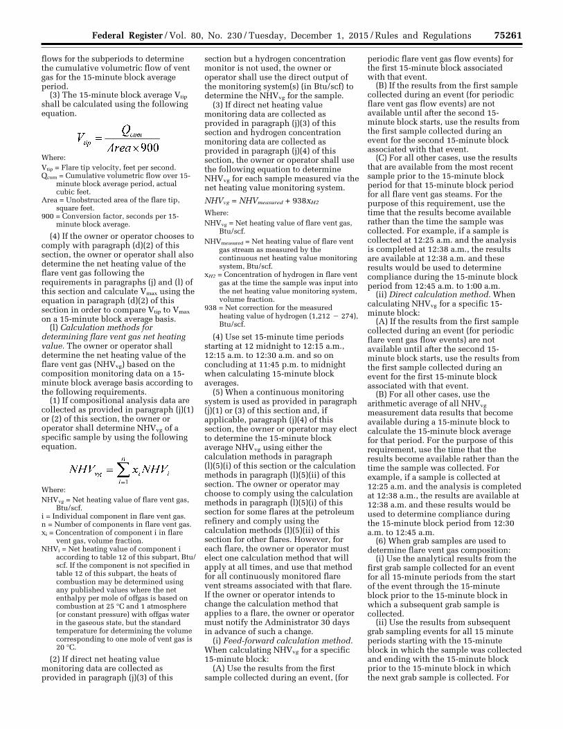
75261 Federal Register / Vol. 80, No. 230 / Tuesday, December 1, 2015 / Rules and Regulations
flows for the subperiods to determine the cumulative volumetric flow of vent gas for the 15-minute block average period.
(3) The 15-minute block average Vtip shall be calculated using the following equation.
Where: Vtip = Flare tip velocity, feet per second. Qcum = Cumulative volumetric flow over 15-
minute block average period, actual cubic feet.
Area = Unobstructed area of the flare tip, square feet.
900 = Conversion factor, seconds per 15- minute block average.
(4) If the owner or operator chooses to comply with paragraph (d)(2) of this section, the owner or operator shall also determine the net heating value of the flare vent gas following the requirements in paragraphs (j) and (l) of this section and calculate Vmax using the equation in paragraph (d)(2) of this section in order to compare Vtip to Vmax on a 15-minute block average basis.
(l) Calculation methods for determining flare vent gas net heating value. The owner or operator shall determine the net heating value of the flare vent gas (NHVvg) based on the composition monitoring data on a 15- minute block average basis according to the following requirements.
(1) If compositional analysis data are collected as provided in paragraph (j)(1) or (2) of this section, the owner or operator shall determine NHVvg of a specific sample by using the following equation.
Where: NHVvg = Net heating value of flare vent gas,
Btu/scf. i = Individual component in flare vent gas. n = Number of components in flare vent gas. xi = Concentration of component i in flare
vent gas, volume fraction. NHVi = Net heating value of component i
according to table 12 of this subpart, Btu/ scf. If the component is not specified in table 12 of this subpart, the heats of combustion may be determined using any published values where the net enthalpy per mole of offgas is based on combustion at 25 °C and 1 atmosphere (or constant pressure) with offgas water in the gaseous state, but the standard temperature for determining the volume corresponding to one mole of vent gas is 20 °C.
(2) If direct net heating value monitoring data are collected as provided in paragraph (j)(3) of this
section but a hydrogen concentration monitor is not used, the owner or operator shall use the direct output of the monitoring system(s) (in Btu/scf) to determine the NHVvg for the sample.
(3) If direct net heating value monitoring data are collected as provided in paragraph (j)(3) of this section and hydrogen concentration monitoring data are collected as provided in paragraph (j)(4) of this section, the owner or operator shall use the following equation to determine NHVvg for each sample measured via the net heating value monitoring system.
NHVvg = NHVmeasured + 938xH2
Where: NHVvg = Net heating value of flare vent gas,
Btu/scf. NHVmeasured = Net heating value of flare vent
gas stream as measured by the continuous net heating value monitoring system, Btu/scf.
xH2 = Concentration of hydrogen in flare vent gas at the time the sample was input into the net heating value monitoring system, volume fraction.
938 = Net correction for the measured heating value of hydrogen (1,212 ¥ 274), Btu/scf.
(4) Use set 15-minute time periods starting at 12 midnight to 12:15 a.m., 12:15 a.m. to 12:30 a.m. and so on concluding at 11:45 p.m. to midnight when calculating 15-minute block averages.
(5) When a continuous monitoring system is used as provided in paragraph (j)(1) or (3) of this section and, if applicable, paragraph (j)(4) of this section, the owner or operator may elect to determine the 15-minute block average NHVvg using either the calculation methods in paragraph (l)(5)(i) of this section or the calculation methods in paragraph (l)(5)(ii) of this section. The owner or operator may choose to comply using the calculation methods in paragraph (l)(5)(i) of this section for some flares at the petroleum refinery and comply using the calculation methods (l)(5)(ii) of this section for other flares. However, for each flare, the owner or operator must elect one calculation method that will apply at all times, and use that method for all continuously monitored flare vent streams associated with that flare. If the owner or operator intends to change the calculation method that applies to a flare, the owner or operator must notify the Administrator 30 days in advance of such a change.
(i) Feed-forward calculation method. When calculating NHVvg for a specific 15-minute block:
(A) Use the results from the first sample collected during an event, (for
periodic flare vent gas flow events) for the first 15-minute block associated with that event.
(B) If the results from the first sample collected during an event (for periodic flare vent gas flow events) are not available until after the second 15- minute block starts, use the results from the first sample collected during an event for the second 15-minute block associated with that event.
(C) For all other cases, use the results that are available from the most recent sample prior to the 15-minute block period for that 15-minute block period for all flare vent gas steams. For the purpose of this requirement, use the time that the results become available rather than the time the sample was collected. For example, if a sample is collected at 12:25 a.m. and the analysis is completed at 12:38 a.m., the results are available at 12:38 a.m. and these results would be used to determine compliance during the 15-minute block period from 12:45 a.m. to 1:00 a.m.
(ii) Direct calculation method. When calculating NHVvg for a specific 15- minute block:
(A) If the results from the first sample collected during an event (for periodic flare vent gas flow events) are not available until after the second 15- minute block starts, use the results from the first sample collected during an event for the first 15-minute block associated with that event.
(B) For all other cases, use the arithmetic average of all NHVvg measurement data results that become available during a 15-minute block to calculate the 15-minute block average for that period. For the purpose of this requirement, use the time that the results become available rather than the time the sample was collected. For example, if a sample is collected at 12:25 a.m. and the analysis is completed at 12:38 a.m., the results are available at 12:38 a.m. and these results would be used to determine compliance during the 15-minute block period from 12:30 a.m. to 12:45 a.m.
(6) When grab samples are used to determine flare vent gas composition:
(i) Use the analytical results from the first grab sample collected for an event for all 15-minute periods from the start of the event through the 15-minute block prior to the 15-minute block in which a subsequent grab sample is collected.
(ii) Use the results from subsequent grab sampling events for all 15 minute periods starting with the 15-minute block in which the sample was collected and ending with the 15-minute block prior to the 15-minute block in which the next grab sample is collected. For
VerDate Sep<11>2014 23:11 Nov 30, 2015 Jkt 238001 PO 00000 Frm 00085 Fmt 4701 Sfmt 4700 E:\FR\FM\01DER2.SGM 01DER2 ER
01D
E15
.010
</G
PH
>E
R01
DE
15.0
11<
/GP
H>
tkel
ley
on D
SK
3SP
TV
N1P
RO
D w
ith R
ULE
S2
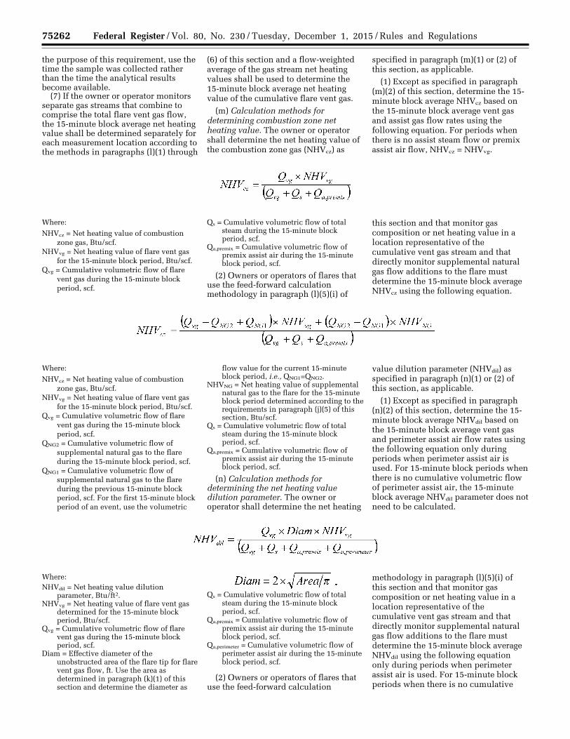
75262 Federal Register / Vol. 80, No. 230 / Tuesday, December 1, 2015 / Rules and Regulations
the purpose of this requirement, use the time the sample was collected rather than the time the analytical results become available.
(7) If the owner or operator monitors separate gas streams that combine to comprise the total flare vent gas flow, the 15-minute block average net heating value shall be determined separately for each measurement location according to the methods in paragraphs (l)(1) through
(6) of this section and a flow-weighted average of the gas stream net heating values shall be used to determine the 15-minute block average net heating value of the cumulative flare vent gas.
(m) Calculation methods for determining combustion zone net heating value. The owner or operator shall determine the net heating value of the combustion zone gas (NHVcz) as
specified in paragraph (m)(1) or (2) of this section, as applicable.
(1) Except as specified in paragraph (m)(2) of this section, determine the 15- minute block average NHVcz based on the 15-minute block average vent gas and assist gas flow rates using the following equation. For periods when there is no assist steam flow or premix assist air flow, NHVcz = NHVvg.
Where:
NHVcz = Net heating value of combustion zone gas, Btu/scf.
NHVvg = Net heating value of flare vent gas for the 15-minute block period, Btu/scf.
Qvg = Cumulative volumetric flow of flare vent gas during the 15-minute block period, scf.
Qs = Cumulative volumetric flow of total steam during the 15-minute block period, scf.
Qa,premix = Cumulative volumetric flow of premix assist air during the 15-minute block period, scf.
(2) Owners or operators of flares that use the feed-forward calculation methodology in paragraph (l)(5)(i) of
this section and that monitor gas composition or net heating value in a location representative of the cumulative vent gas stream and that directly monitor supplemental natural gas flow additions to the flare must determine the 15-minute block average NHVcz using the following equation.
Where:
NHVcz = Net heating value of combustion zone gas, Btu/scf.
NHVvg = Net heating value of flare vent gas for the 15-minute block period, Btu/scf.
Qvg = Cumulative volumetric flow of flare vent gas during the 15-minute block period, scf.
QNG2 = Cumulative volumetric flow of supplemental natural gas to the flare during the 15-minute block period, scf.
QNG1 = Cumulative volumetric flow of supplemental natural gas to the flare during the previous 15-minute block period, scf. For the first 15-minute block period of an event, use the volumetric
flow value for the current 15-minute block period, i.e., QNG1=QNG2.
NHVNG = Net heating value of supplemental natural gas to the flare for the 15-minute block period determined according to the requirements in paragraph (j)(5) of this section, Btu/scf.
Qs = Cumulative volumetric flow of total steam during the 15-minute block period, scf.
Qa,premix = Cumulative volumetric flow of premix assist air during the 15-minute block period, scf.
(n) Calculation methods for determining the net heating value dilution parameter. The owner or operator shall determine the net heating
value dilution parameter (NHVdil) as specified in paragraph (n)(1) or (2) of this section, as applicable.
(1) Except as specified in paragraph (n)(2) of this section, determine the 15- minute block average NHVdil based on the 15-minute block average vent gas and perimeter assist air flow rates using the following equation only during periods when perimeter assist air is used. For 15-minute block periods when there is no cumulative volumetric flow of perimeter assist air, the 15-minute block average NHVdil parameter does not need to be calculated.
Where: NHVdil = Net heating value dilution
parameter, Btu/ft2. NHVvg = Net heating value of flare vent gas
determined for the 15-minute block period, Btu/scf.
Qvg = Cumulative volumetric flow of flare vent gas during the 15-minute block period, scf.
Diam = Effective diameter of the unobstructed area of the flare tip for flare vent gas flow, ft. Use the area as determined in paragraph (k)(1) of this section and determine the diameter as
Qs = Cumulative volumetric flow of total steam during the 15-minute block period, scf.
Qa,premix = Cumulative volumetric flow of premix assist air during the 15-minute block period, scf.
Qa,perimeter = Cumulative volumetric flow of perimeter assist air during the 15-minute block period, scf.
(2) Owners or operators of flares that use the feed-forward calculation
methodology in paragraph (l)(5)(i) of this section and that monitor gas composition or net heating value in a location representative of the cumulative vent gas stream and that directly monitor supplemental natural gas flow additions to the flare must determine the 15-minute block average NHVdil using the following equation only during periods when perimeter assist air is used. For 15-minute block periods when there is no cumulative
VerDate Sep<11>2014 23:11 Nov 30, 2015 Jkt 238001 PO 00000 Frm 00086 Fmt 4701 Sfmt 4700 E:\FR\FM\01DER2.SGM 01DER2 ER
01D
E15
.012
</G
PH
>E
R01
DE
15.0
13<
/GP
H>
ER
01D
E15
.014
</G
PH
>E
R01
DE
15.0
15<
/GP
H>
tkel
ley
on D
SK
3SP
TV
N1P
RO
D w
ith R
ULE
S2
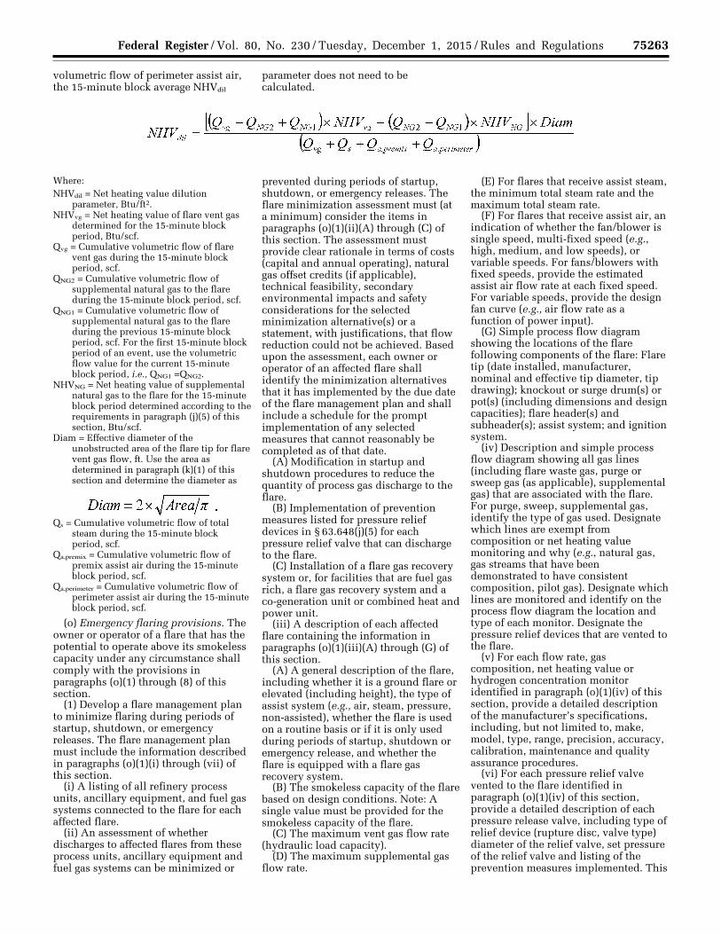
75263 Federal Register / Vol. 80, No. 230 / Tuesday, December 1, 2015 / Rules and Regulations
volumetric flow of perimeter assist air, the 15-minute block average NHVdil
parameter does not need to be calculated.
Where: NHVdil = Net heating value dilution
parameter, Btu/ft2. NHVvg = Net heating value of flare vent gas
determined for the 15-minute block period, Btu/scf.
Qvg = Cumulative volumetric flow of flare vent gas during the 15-minute block period, scf.
QNG2 = Cumulative volumetric flow of supplemental natural gas to the flare during the 15-minute block period, scf.
QNG1 = Cumulative volumetric flow of supplemental natural gas to the flare during the previous 15-minute block period, scf. For the first 15-minute block period of an event, use the volumetric flow value for the current 15-minute block period, i.e., QNG1 =QNG2.
NHVNG = Net heating value of supplemental natural gas to the flare for the 15-minute block period determined according to the requirements in paragraph (j)(5) of this section, Btu/scf.
Diam = Effective diameter of the unobstructed area of the flare tip for flare vent gas flow, ft. Use the area as determined in paragraph (k)(1) of this section and determine the diameter as
Qs = Cumulative volumetric flow of total steam during the 15-minute block period, scf.
Qa,premix = Cumulative volumetric flow of premix assist air during the 15-minute block period, scf.
Qa,perimeter = Cumulative volumetric flow of perimeter assist air during the 15-minute block period, scf.
(o) Emergency flaring provisions. The owner or operator of a flare that has the potential to operate above its smokeless capacity under any circumstance shall comply with the provisions in paragraphs (o)(1) through (8) of this section.
(1) Develop a flare management plan to minimize flaring during periods of startup, shutdown, or emergency releases. The flare management plan must include the information described in paragraphs (o)(1)(i) through (vii) of this section.
(i) A listing of all refinery process units, ancillary equipment, and fuel gas systems connected to the flare for each affected flare.
(ii) An assessment of whether discharges to affected flares from these process units, ancillary equipment and fuel gas systems can be minimized or
prevented during periods of startup, shutdown, or emergency releases. The flare minimization assessment must (at a minimum) consider the items in paragraphs (o)(1)(ii)(A) through (C) of this section. The assessment must provide clear rationale in terms of costs (capital and annual operating), natural gas offset credits (if applicable), technical feasibility, secondary environmental impacts and safety considerations for the selected minimization alternative(s) or a statement, with justifications, that flow reduction could not be achieved. Based upon the assessment, each owner or operator of an affected flare shall identify the minimization alternatives that it has implemented by the due date of the flare management plan and shall include a schedule for the prompt implementation of any selected measures that cannot reasonably be completed as of that date.
(A) Modification in startup and shutdown procedures to reduce the quantity of process gas discharge to the flare.
(B) Implementation of prevention measures listed for pressure relief devices in § 63.648(j)(5) for each pressure relief valve that can discharge to the flare.
(C) Installation of a flare gas recovery system or, for facilities that are fuel gas rich, a flare gas recovery system and a co-generation unit or combined heat and power unit.
(iii) A description of each affected flare containing the information in paragraphs (o)(1)(iii)(A) through (G) of this section.
(A) A general description of the flare, including whether it is a ground flare or elevated (including height), the type of assist system (e.g., air, steam, pressure, non-assisted), whether the flare is used on a routine basis or if it is only used during periods of startup, shutdown or emergency release, and whether the flare is equipped with a flare gas recovery system.
(B) The smokeless capacity of the flare based on design conditions. Note: A single value must be provided for the smokeless capacity of the flare.
(C) The maximum vent gas flow rate (hydraulic load capacity).
(D) The maximum supplemental gas flow rate.
(E) For flares that receive assist steam, the minimum total steam rate and the maximum total steam rate.
(F) For flares that receive assist air, an indication of whether the fan/blower is single speed, multi-fixed speed (e.g., high, medium, and low speeds), or variable speeds. For fans/blowers with fixed speeds, provide the estimated assist air flow rate at each fixed speed. For variable speeds, provide the design fan curve (e.g., air flow rate as a function of power input).
(G) Simple process flow diagram showing the locations of the flare following components of the flare: Flare tip (date installed, manufacturer, nominal and effective tip diameter, tip drawing); knockout or surge drum(s) or pot(s) (including dimensions and design capacities); flare header(s) and subheader(s); assist system; and ignition system.
(iv) Description and simple process flow diagram showing all gas lines (including flare waste gas, purge or sweep gas (as applicable), supplemental gas) that are associated with the flare. For purge, sweep, supplemental gas, identify the type of gas used. Designate which lines are exempt from composition or net heating value monitoring and why (e.g., natural gas, gas streams that have been demonstrated to have consistent composition, pilot gas). Designate which lines are monitored and identify on the process flow diagram the location and type of each monitor. Designate the pressure relief devices that are vented to the flare.
(v) For each flow rate, gas composition, net heating value or hydrogen concentration monitor identified in paragraph (o)(1)(iv) of this section, provide a detailed description of the manufacturer’s specifications, including, but not limited to, make, model, type, range, precision, accuracy, calibration, maintenance and quality assurance procedures.
(vi) For each pressure relief valve vented to the flare identified in paragraph (o)(1)(iv) of this section, provide a detailed description of each pressure release valve, including type of relief device (rupture disc, valve type) diameter of the relief valve, set pressure of the relief valve and listing of the prevention measures implemented. This
VerDate Sep<11>2014 23:11 Nov 30, 2015 Jkt 238001 PO 00000 Frm 00087 Fmt 4701 Sfmt 4700 E:\FR\FM\01DER2.SGM 01DER2 ER
01D
E15
.016
</G
PH
>E
R01
DE
15.0
17<
/GP
H>
tkel
ley
on D
SK
3SP
TV
N1P
RO
D w
ith R
ULE
S2
75264 Federal Register / Vol. 80, No. 230 / Tuesday, December 1, 2015 / Rules and Regulations
information may be maintained in an electronic database on-site and does not need to be submitted as part of the flare management plan unless requested to do so by the Administrator.
(vii) Procedures to minimize or eliminate discharges to the flare during the planned startup and shutdown of the refinery process units and ancillary equipment that are connected to the affected flare, together with a schedule for the prompt implementation of any procedures that cannot reasonably be implemented as of the date of the submission of the flare management plan.
(2) Each owner or operator required to develop and implement a written flare management plan as described in paragraph (o)(1) of this section must submit the plan to the Administrator as described in paragraphs (o)(2)(i) through (iii) of this section.
(i) The owner or operator must develop and implement the flare management plan no later than January 30, 2019 or at startup for a new flare that commenced construction on or after February 1, 2016.
(ii) The owner or operator must comply with the plan as submitted by the date specified in paragraph (o)(2)(i) of this section. The plan should be updated periodically to account for changes in the operation of the flare, such as new connections to the flare or the installation of a flare gas recovery system, but the plan need be re- submitted to the Administrator only if the owner or operator alters the design smokeless capacity of the flare. The owner or operator must comply with the updated plan as submitted.
(iii) All versions of the plan submitted to the Administrator shall also be submitted to the following address: U.S. Environmental Protection Agency, Office of Air Quality Planning and Standards, Sector Policies and Programs Division, U.S. EPA Mailroom (E143–01), Attention: Refinery Sector Lead, 109 T.W. Alexander Drive, Research Triangle Park, NC 27711. Electronic copies in lieu of hard copies may also be submitted to [email protected].
(3) The owner or operator of a flare subject to this subpart shall conduct a root cause analysis and a corrective action analysis for each flow event that contains regulated material and that meets either the criteria in paragraph (o)(3)(i) or (ii) of this section.
(i) The vent gas flow rate exceeds the smokeless capacity of the flare and visible emissions are present from the flare for more than 5 minutes during any 2 consecutive hours during the release event.
(ii) The vent gas flow rate exceeds the smokeless capacity of the flare and the 15-minute block average flare tip velocity exceeds the maximum flare tip velocity determined using the methods in paragraph (d)(2) of this section.
(4) A root cause analysis and corrective action analysis must be completed as soon as possible, but no later than 45 days after a flare flow event meeting the criteria in paragraph (o)(3)(i) or (ii) of this section. Special circumstances affecting the number of root cause analyses and/or corrective action analyses are provided in paragraphs (o)(4)(i) through (v) of this section.
(i) You may conduct a single root cause analysis and corrective action analysis for a single continuous flare flow event that meets both of the criteria in paragraphs (o)(3)(i) and (ii) of this section.
(ii) You may conduct a single root cause analysis and corrective action analysis for a single continuous flare flow event regardless of the number of 15-minute block periods in which the flare tip velocity was exceeded or the number of 2 hour periods that contain more the 5 minutes of visible emissions.
(iii) You may conduct a single root cause analysis and corrective action analysis for a single event that causes two or more flares that are operated in series (i.e., cascaded flare systems) to have a flow event meeting the criteria in paragraph (o)(3)(i) or (ii) of this section.
(iv) You may conduct a single root cause analysis and corrective action analysis for a single event that causes two or more flares to have a flow event meeting the criteria in paragraph (o)(3)(i) or (ii) of this section, regardless of the configuration of the flares, if the root cause is reasonably expected to be a force majeure event, as defined in this subpart.
(v) Except as provided in paragraphs (o)(4)(iii) and (iv) of this section, if more than one flare has a flow event that meets the criteria in paragraph (o)(3)(i) or (ii) of this section during the same time period, an initial root cause analysis shall be conducted separately for each flare that has a flow event meeting the criteria in paragraph (o)(3)(i) or (ii) of this section. If the initial root cause analysis indicates that the flow events have the same root cause(s), the initially separate root cause analyses may be recorded as a single root cause analysis and a single corrective action analysis may be conducted.
(5) Each owner or operator of a flare required to conduct a root cause analysis and corrective action analysis as specified in paragraphs (o)(3) and (4)
of this section shall implement the corrective action(s) identified in the corrective action analysis in accordance with the applicable requirements in paragraphs (o)(5)(i) through (iii) of this section.
(i) All corrective action(s) must be implemented within 45 days of the event for which the root cause and corrective action analyses were required or as soon thereafter as practicable. If an owner or operator concludes that no corrective action should be implemented, the owner or operator shall record and explain the basis for that conclusion no later than 45 days following the event.
(ii) For corrective actions that cannot be fully implemented within 45 days following the event for which the root cause and corrective action analyses were required, the owner or operator shall develop an implementation schedule to complete the corrective action(s) as soon as practicable.
(iii) No later than 45 days following the event for which a root cause and corrective action analyses were required, the owner or operator shall record the corrective action(s) completed to date, and, for action(s) not already completed, a schedule for implementation, including proposed commencement and completion dates.
(6) The owner or operator shall determine the total number of events for which a root cause and corrective action analyses was required during the calendar year for each affected flare separately for events meeting the criteria in paragraph (o)(3)(i) of this section and those meeting the criteria in paragraph (o)(3)(ii) of this section. For the purpose of this requirement, a single root cause analysis conducted for an event that met both of the criteria in paragraphs (o)(3)(i) and (ii) of this section would be counted as an event under each of the separate criteria counts for that flare. Additionally, if a single root cause analysis was conducted for an event that caused multiple flares to meet the criteria in paragraph (o)(3)(i) or (ii) of this section, that event would count as an event for each of the flares for each criteria in paragraph (o)(3) of this section that was met during that event. The owner or operator shall also determine the total number of events for which a root cause and correct action analyses was required and the analyses concluded that the root cause was a force majeure event, as defined in this subpart.
(7) The following events would be a violation of this emergency flaring work practice standard.
(i) Any flow event for which a root cause analysis was required and the root
VerDate Sep<11>2014 23:11 Nov 30, 2015 Jkt 238001 PO 00000 Frm 00088 Fmt 4701 Sfmt 4700 E:\FR\FM\01DER2.SGM 01DER2tkel
ley
on D
SK
3SP
TV
N1P
RO
D w
ith R
ULE
S2
75265 Federal Register / Vol. 80, No. 230 / Tuesday, December 1, 2015 / Rules and Regulations
cause was determined to be operator error or poor maintenance.
(ii) Two visible emissions exceedance events meeting the criteria in paragraph (o)(3)(i) of this section that were not caused by a force majeure event from a single flare in a 3 calendar year period for the same root cause for the same equipment.
(iii) Two flare tip velocity exceedance events meeting the criteria in paragraph (o)(3)(ii) of this section that were not caused by a force majeure event from a single flare in a 3 calendar year period for the same root cause for the same equipment.
(iv) Three visible emissions exceedance events meeting the criteria in paragraph (o)(3)(i) of this section that were not caused by a force majeure event from a single flare in a 3 calendar year period for any reason.
(v) Three flare tip velocity exceedance events meeting the criteria in paragraph (o)(3)(ii) of this section that were not caused by a force majeure event from a single flare in a 3 calendar year period for any reason.
(p) Flare monitoring records. The owner or operator shall keep the records specified in § 63.655(i)(9).
(q) Reporting. The owner or operator shall comply with the reporting requirements specified in § 63.655(g)(11).
(r) Alternative means of emissions limitation. An owner or operator may request approval from the Administrator for site-specific operating limits that shall apply specifically to a selected flare. Site-specific operating limits include alternative threshold values for the parameters specified in paragraphs (d) through (f) of this section as well as threshold values for operating parameters other than those specified in paragraphs (d) through (f) of this section. The owner or operator must demonstrate that the flare achieves 96.5 percent combustion efficiency (or 98 percent destruction efficiency) using the site-specific operating limits based on a performance evaluation as described in paragraph (r)(1) of this section. The request shall include information as described in paragraph (r)(2) of this section. The request shall be submitted and followed as described in paragraph (r)(3) of this section.
(1) The owner or operator shall prepare and submit a site-specific test plan and receive approval of the site- specific performance evaluation plan prior to conducting any flare performance evaluation test runs intended for use in developing site- specific operating limits. The site- specific performance evaluation plan shall include, at a minimum, the
elements specified in paragraphs (r)(1)(i) through (ix) of this section. Upon approval of the site-specific performance evaluation plan, the owner or operator shall conduct performance evaluation test runs for the flare following the procedures described in the site-specific performance evaluation plan.
(i) The design and dimensions of the flare, flare type (air-assisted only, steam- assisted only, air- and steam-assisted, pressure-assisted, or non-assisted), and description of gas being flared, including quantity of gas flared, frequency of flaring events (if periodic), expected net heating value of flare vent gas, minimum total steam assist rate.
(ii) The operating conditions (vent gas compositions, vent gas flow rates and assist flow rates, if applicable) likely to be encountered by the flare during normal operations and the operating conditions for the test period.
(iii) A description of (including sample calculations illustrating) the planned data reduction and calculations to determine the flare combustion or destruction efficiency.
(iv) Site-specific operating parameters to be monitored continuously during the flare performance evaluation. These parameters may include but are not limited to vent gas flow rate, steam and/ or air assist flow rates, and flare vent gas composition. If new operating parameters are proposed for use other than those specified in paragraphs (d) through (f) of this section, an explanation of the relevance of the proposed operating parameter(s) as an indicator of flare combustion performance and why the alternative operating parameter(s) can adequately ensure that the flare achieves the required combustion efficiency.
(v) A detailed description of the measurement methods, monitored pollutant(s), measurement locations, measurement frequency, and recording frequency proposed for both emission measurements and flare operating parameters.
(vi) A description of (including sample calculations illustrating) the planned data reduction and calculations to determine the flare operating parameters.
(vii) The minimum number and length of test runs and range of operating values to be evaluated during the performance evaluation. A sufficient number of test runs shall be conducted to identify the point at which the combustion/destruction efficiency of the flare deteriorates.
(viii) [Reserved] (ix) Test schedule.
(2) The request for flare-specific operating limits shall include sufficient and appropriate data, as determined by the Administrator, to allow the Administrator to confirm that the selected site-specific operating limit(s) adequately ensures that the flare destruction efficiency is 98 percent or greater or that the flare combustion efficiency is 96.5 percent or greater at all times. At a minimum, the request shall contain the information described in paragraphs (r)(2)(i) through (iv) of this section.
(i) The design and dimensions of the flare, flare type (air-assisted only, steam- assisted only, air- and steam-assisted, pressure-assisted, or non-assisted), and description of gas being flared, including quantity of gas flared, frequency of flaring events (if periodic), expected net heating value of flare vent gas, minimum total steam assist rate.
(ii) Results of each performance evaluation test run conducted, including, at a minimum:
(A) The measured combustion/destruction efficiency.
(B) The measured or calculated operating parameters for each test run. If operating parameters are calculated, the raw data from which the parameters are calculated must be included in the test report.
(C) Measurement location descriptions for both emission measurements and flare operating parameters.
(D) Description of sampling and analysis procedures (including number and length of test runs) and any modifications to standard procedures. If there were deviations from the approved test plan, a detailed description of the deviations and rationale why the test results or calculation procedures used are appropriate.
(E) Operating conditions (e.g., vent gas composition, assist rates, etc.) that occurred during the test.
(F) Quality assurance procedures. (G) Records of calibrations. (H) Raw data sheets for field
sampling. (I) Raw data sheets for field and
laboratory analyses. (J) Documentation of calculations. (iii) The selected flare-specific
operating limit values based on the performance evaluation test results, including the averaging time for the operating limit(s), and rationale why the selected values and averaging times are sufficiently stringent to ensure proper flare performance. If new operating parameters or averaging times are proposed for use other than those specified in paragraphs (d) through (f) of this section, an explanation of why the
VerDate Sep<11>2014 23:11 Nov 30, 2015 Jkt 238001 PO 00000 Frm 00089 Fmt 4701 Sfmt 4700 E:\FR\FM\01DER2.SGM 01DER2tkel
ley
on D
SK
3SP
TV
N1P
RO
D w
ith R
ULE
S2
75266 Federal Register / Vol. 80, No. 230 / Tuesday, December 1, 2015 / Rules and Regulations
alternative operating parameter(s) or averaging time(s) adequately ensures the flare achieves the required combustion efficiency.
(iv) The means by which the owner or operator will document on-going, continuous compliance with the selected flare-specific operating limit(s), including the specific measurement location and frequencies, calculation procedures, and records to be maintained.
(3) The request shall be submitted as described in paragraphs (r)(3)(i) through (iv) of this section.
(i) The owner or operator may request approval from the Administrator at any time upon completion of a performance evaluation conducted following the methods in an approved site-specific performance evaluation plan for an operating limit(s) that shall apply specifically to that flare.
(ii) The request must be submitted to the Administrator for approval. The owner or operator must continue to comply with the applicable standards for flares in this subpart until the requirements in § 63.6(g)(1) are met and a notice is published in the Federal Register allowing use of such an alternative means of emission limitation.
(iii) The request shall also be submitted to the following address: U.S. Environmental Protection Agency, Office of Air Quality Planning and Standards, Sector Policies and Programs Division, U.S. EPA Mailroom (E143–01), Attention: Refinery Sector Lead, 109 T.W. Alexander Drive, Research Triangle Park, NC 27711. Electronic copies in lieu of hard copies may also be submitted to [email protected].
(iv) If the Administrator finds any deficiencies in the request, the request must be revised to address the deficiencies and be re-submitted for approval within 45 days of receipt of the notice of deficiencies. The owner or operator must comply with the revised request as submitted until it is approved.
(4) The approval process for a request for a flare-specific operating limit(s) is described in paragraphs (r)(4)(i) through (iii) of this section.
(i) Approval by the Administrator of a flare-specific operating limit(s) request will be based on the completeness, accuracy and reasonableness of the request. Factors that the EPA will consider in reviewing the request for approval include, but are not limited to, those described in paragraphs (r)(4)(i)(A) through (C) of this section.
(A) The description of the flare design and operating characteristics.
(B) If a new operating parameter(s) other than those specified in paragraphs (d) through (f) of this section is proposed, the explanation of how the proposed operating parameter(s) serves a good indicator(s) of flare combustion performance.
(C) The results of the flare performance evaluation test runs and the establishment of operating limits that ensures that the flare destruction efficiency is 98 percent or greater or that the flare combustion efficiency is 96.5 percent or greater at all times.
(D) The completeness of the flare performance evaluation test report.
(ii) If the request is approved by the Administrator, a flare-specific operating limit(s) will be established at the level(s) demonstrated in the approved request.
(iii) If the Administrator finds any deficiencies in the request, the request must be revised to address the deficiencies and be re-submitted for approval. ■ 33. Section 63.671 is added to read as follows:
§ 63.671 Requirements for flare monitoring systems.
(a) Operation of CPMS. For each CPMS installed to comply with applicable provisions in § 63.670, the owner or operator shall install, operate, calibrate, and maintain the CPMS as specified in paragraphs (a)(1) through (8) of this section.
(1) Except for CPMS installed for pilot flame monitoring, all monitoring equipment must meet the applicable minimum accuracy, calibration and quality control requirements specified in table 13 of this subpart.
(2) The owner or operator shall ensure the readout (that portion of the CPMS that provides a visual display or record) or other indication of the monitored operating parameter from any CPMS required for compliance is readily accessible onsite for operational control or inspection by the operator of the source.
(3) All CPMS must complete a minimum of one cycle of operation (sampling, analyzing and data recording) for each successive 15- minute period.
(4) Except for periods of monitoring system malfunctions, repairs associated with monitoring system malfunctions and required monitoring system quality assurance or quality control activities (including, as applicable, calibration checks and required zero and span adjustments), the owner or operator shall operate all CPMS and collect data continuously at all times when regulated emissions are routed to the flare.
(5) The owner or operator shall operate, maintain, and calibrate each CPMS according to the CPMS monitoring plan specified in paragraph (b) of this section.
(6) For each CPMS except for CPMS installed for pilot flame monitoring, the owner or operator shall comply with the out-of-control procedures described in paragraph (c) of this section.
(7) The owner or operator shall reduce data from a CPMS as specified in paragraph (d) of this section.
(8) The CPMS must be capable of measuring the appropriate parameter over the range of values expected for that measurement location. The data recording system associated with each CPMS must have a resolution that is equal to or better than the required system accuracy.
(b) CPMS monitoring plan. The owner or operator shall develop and implement a CPMS quality control program documented in a CPMS monitoring plan that covers each flare subject to the provisions in § 63.670 and each CPMS installed to comply with applicable provisions in § 63.670. The owner or operator shall have the CPMS monitoring plan readily available on- site at all times and shall submit a copy of the CPMS monitoring plan to the Administrator upon request by the Administrator. The CPMS monitoring plan must contain the information listed in paragraphs (b)(1) through (5) of this section.
(1) Identification of the specific flare being monitored and the flare type (air- assisted only, steam-assisted only, air- and steam-assisted, pressure-assisted, or non-assisted).
(2) Identification of the parameter to be monitored by the CPMS and the expected parameter range, including worst case and normal operation.
(3) Description of the monitoring equipment, including the information specified in paragraphs (b)(3)(i) through (vii) of this section.
(i) Manufacturer and model number for all monitoring equipment components installed to comply with applicable provisions in § 63.670.
(ii) Performance specifications, as provided by the manufacturer, and any differences expected for this installation and operation.
(iii) The location of the CPMS sampling probe or other interface and a justification of how the location meets the requirements of paragraph (a)(1) of this section.
(iv) Placement of the CPMS readout, or other indication of parameter values, indicating how the location meets the requirements of paragraph (a)(2) of this section.
VerDate Sep<11>2014 23:11 Nov 30, 2015 Jkt 238001 PO 00000 Frm 00090 Fmt 4701 Sfmt 4700 E:\FR\FM\01DER2.SGM 01DER2tkel
ley
on D
SK
3SP
TV
N1P
RO
D w
ith R
ULE
S2
75267 Federal Register / Vol. 80, No. 230 / Tuesday, December 1, 2015 / Rules and Regulations
(v) Span of the CPMS. The span of the CPMS sensor and analyzer must encompass the full range of all expected values.
(vi) How data outside of the span of the CPMS will be handled and the corrective action that will be taken to reduce and eliminate such occurrences in the future.
(vii) Identification of the parameter detected by the parametric signal analyzer and the algorithm used to convert these values into the operating parameter monitored to demonstrate compliance, if the parameter detected is different from the operating parameter monitored.
(4) Description of the data collection and reduction systems, including the information specified in paragraphs (b)(4)(i) through (iii) of this section.
(i) A copy of the data acquisition system algorithm used to reduce the measured data into the reportable form of the standard and to calculate the applicable averages.
(ii) Identification of whether the algorithm excludes data collected during CPMS breakdowns, out-of- control periods, repairs, maintenance periods, instrument adjustments or checks to maintain precision and accuracy, calibration checks, and zero (low-level), mid-level (if applicable) and high-level adjustments.
(iii) If the data acquisition algorithm does not exclude data collected during CPMS breakdowns, out-of-control periods, repairs, maintenance periods, instrument adjustments or checks to maintain precision and accuracy, calibration checks, and zero (low-level), mid-level (if applicable) and high-level adjustments, a description of the procedure for excluding this data when the averages calculated as specified in paragraph (e) of this section are determined.
(5) Routine quality control and assurance procedures, including descriptions of the procedures listed in paragraphs (b)(5)(i) through (vi) of this section and a schedule for conducting these procedures. The routine procedures must provide an assessment of CPMS performance.
(i) Initial and subsequent calibration of the CPMS and acceptance criteria.
(ii) Determination and adjustment of the calibration drift of the CPMS.
(iii) Daily checks for indications that the system is responding. If the CPMS system includes an internal system check, the owner or operator may use the results to verify the system is responding, as long as the system provides an alarm to the owner or operator or the owner or operator checks the internal system results daily for
proper operation and the results are recorded.
(iv) Preventive maintenance of the CPMS, including spare parts inventory.
(v) Data recording, calculations and reporting.
(vi) Program of corrective action for a CPMS that is not operating properly.
(c) Out-of-control periods. For each CPMS installed to comply with applicable provisions in § 63.670 except for CPMS installed for pilot flame monitoring, the owner or operator shall comply with the out-of-control procedures described in paragraphs (c)(1) and (2) of this section.
(1) A CPMS is out-of-control if the zero (low-level), mid-level (if applicable) or high-level calibration drift exceeds two times the accuracy requirement of table 13 of this subpart.
(2) When the CPMS is out of control, the owner or operator shall take the necessary corrective action and repeat all necessary tests that indicate the system is out of control. The owner or operator shall take corrective action and conduct retesting until the performance requirements are below the applicable limits. The beginning of the out-of- control period is the hour a performance check (e.g., calibration drift) that indicates an exceedance of the performance requirements established in this section is conducted. The end of the out-of-control period is the hour following the completion of corrective action and successful demonstration that the system is within the allowable limits. The owner or operator shall not use data recorded during periods the CPMS is out of control in data averages and calculations, used to report emissions or operating levels, as specified in paragraph (d)(3) of this section.
(d) CPMS data reduction. The owner or operator shall reduce data from a CPMS installed to comply with applicable provisions in § 63.670 as specified in paragraphs (d)(1) through (3) of this section.
(1) The owner or operator may round the data to the same number of significant digits used in that operating limit.
(2) Periods of non-operation of the process unit (or portion thereof) resulting in cessation of the emissions to which the monitoring applies must not be included in the 15-minute block averages.
(3) Periods when the CPMS is out of control must not be included in the 15- minute block averages.
(e) Additional requirements for gas chromatographs. For monitors used to determine compositional analysis for net heating value per § 63.670(j)(1), the
gas chromatograph must also meet the requirements of paragraphs (e)(1) through (3) of this section.
(1) The quality assurance requirements are in table 13 of this subpart.
(2) The calibration gases must meet one of the following options:
(i) The owner or operator must use a calibration gas or multiple gases that include all of compounds listed in paragraphs (e)(2)(i)(A) through (K) of this section that may be reasonably expected to exist in the flare gas stream and optionally include any of the compounds listed in paragraphs (e)(2)(i)(L) through (O) of this section. All of the calibration gases may be combined in one cylinder. If multiple calibration gases are necessary to cover all compounds, the owner or operator must calibrate the instrument on all of the gases.
(A) Hydrogen. (B) Methane. (C) Ethane. (D) Ethylene. (E) Propane. (F) Propylene. (G) n-Butane. (H) iso-Butane. (I) Butene (general). It is not necessary
to separately speciate butene isomers, but the net heating value of trans-butene must be used for co-eluting butene isomers.
(J) 1,3-Butadiene. It is not necessary to separately speciate butadiene isomers, but you must use the response factor and net heating value of 1,3-butadiene for co-eluting butadiene isomers.
(K) n-Pentane. Use the response factor for n-pentane to quantify all C5+ hydrocarbons.
(L) Acetylene (optional). (M) Carbon monoxide (optional). (N) Propadiene (optional). (O) Hydrogen sulfide (optional). (ii) The owner or operator must use a
surrogate calibration gas consisting of hydrogen and C1 through C5 normal hydrocarbons. All of the calibration gases may be combined in one cylinder. If multiple calibration gases are necessary to cover all compounds, the owner or operator must calibrate the instrument on all of the gases.
(3) If the owner or operator chooses to use a surrogate calibration gas under paragraph (e)(2)(ii) of this section, the owner or operator must comply with paragraphs (e)(3)(i) and (ii) of this section.
(i) Use the response factor for the nearest normal hydrocarbon (i.e., n- alkane) in the calibration mixture to quantify unknown components detected in the analysis.
(ii) Use the response factor for n- pentane to quantify unknown
VerDate Sep<11>2014 23:11 Nov 30, 2015 Jkt 238001 PO 00000 Frm 00091 Fmt 4701 Sfmt 4700 E:\FR\FM\01DER2.SGM 01DER2tkel
ley
on D
SK
3SP
TV
N1P
RO
D w
ith R
ULE
S2
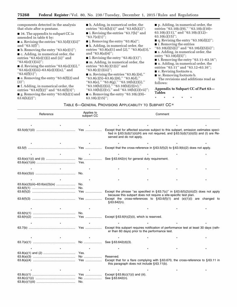
75268 Federal Register / Vol. 80, No. 230 / Tuesday, December 1, 2015 / Rules and Regulations
components detected in the analysis that elute after n-pentane. ■ 34. The appendix to subpart CC is amended in table 6 by: ■ a. Revising the entries ‘‘63.5(d)(1)(ii)’’ and ‘‘63.5(f)’’; ■ b. Removing the entry ‘‘63.6(e)(1)’’; ■ c. Adding, in numerical order, the entries ‘‘63.6(e)(1)(i) and (ii)’’ and ‘‘63.6(e)(1)(iii)’’; ■ d. Revising the entries ‘‘63.6(e)(3)(i),’’ ‘‘63.6(e)(3)(iii)–63.6(e)(3)(ix),’’ and ‘‘63.6(f)(1)’’; ■ e. Removing the entry ‘‘63.6(f)(2) and (3)’’; ■ f. Adding, in numerical order, the entries ‘‘63.6(f)(2)’’ and ‘‘63.6(f)(3)’’; ■ g. Removing the entry ‘‘63.6(h)(1) and 63.6(h)(2)’’;
■ h. Adding, in numerical order, the entries ‘‘63.6(h)(1)’’ and ‘‘63.6(h)(2)’’; ■ i. Revising the entries ‘‘63.7(b)’’ and ‘‘63.7(e)(1)’’; ■ j. Removing the entry ‘‘63.8(a)’’; ■ k. Adding, in numerical order, the entries ‘‘63.8(a)(1) and (2),’’ ‘‘63.8(a)(3),’’ and ‘‘63.8(a)(4)’’; ■ l. Revising the entry ‘‘63.8(c)(1)’’; ■ m. Adding, in numerical order, the entries ‘‘63.8(c)(1)(i)’’ and ‘‘63.8(c)(1)(iii)’’; ■ n. Revising the entries ‘‘63.8(c)(4),’’ ‘‘63.8(c)(5)–63.8(c)(8),’’ ‘‘63.8(d),’’ ‘‘63.8(e),’’ ‘‘63.8(g),’’ ‘‘63.10(b)(2)(i),’’ ‘‘63.10(b)(2)(ii),’’ ‘‘63.10(b)(2)(iv),’’ ‘‘63.10(b)(2)(v),’’ and ‘‘63.10(b)(2)(vii)’’; ■ o. Removing the entry ‘‘63.10(c)(9)– 63.10(c)(15)’’;
■ p. Adding, in numerical order, the entries ‘‘63.10(c)(9),’’ ‘‘63.10(c)(10)– 63.10(c)(11),’’ and ‘‘63.10(c)(12)– 63.10(c)(15)’’; ■ q. Revising the entry ‘‘63.10(d)(2)’’; ■ r. Removing the entries ‘‘63.10(d)(5)(i)’’ and ‘‘63.10(d)(5)(ii)’’; ■ s. Adding, in numerical order, the entry ‘‘63.10(d)(5)’’; ■ t. Removing the entry ‘‘63.11–63.16’’; ■ u. Adding, in numerical order, the entries ‘‘63.11’’ and ‘‘63.12–63.16’’; ■ v. Revising footnote a. ■ w. Removing footnote b.
The revisions and additions read as follows:
Appendix to Subpart CC of Part 63— Tables
* * * * *
TABLE 6—GENERAL PROVISIONS APPLICABILITY TO SUBPART CC a
Reference Applies to subpart CC Comment
* * * * * * * 63.5(d)(1)(ii) ............................................. Yes ................... Except that for affected sources subject to this subpart, emission estimates speci-
fied in § 63.5(d)(1)(ii)(H) are not required, and § 63.5(d)(1)(ii)(G) and (I) are Re-served and do not apply.
* * * * * * * 63.5(f) ....................................................... Yes ................... Except that the cross-reference in § 63.5(f)(2) to § 63.9(b)(2) does not apply.
* * * * * * * 63.6(e)(1)(i) and (ii) .................................. No ..................... See § 63.642(n) for general duty requirement. 63.6(e)(1)(iii) ............................................. Yes.
* * * * * * * 63.6(e)(3)(i) .............................................. No.
* * * * * * * 63.6(e)(3)(iii)–63.6(e)(3)(ix) ...................... No. 63.6(f)(1) .................................................. No. 63.6(f)(2) .................................................. Yes ................... Except the phrase ‘‘as specified in § 63.7(c)’’ in § 63.6(f)(2)(iii)(D) does not apply
because this subpart does not require a site-specific test plan. 63.6(f)(3) .................................................. Yes ................... Except the cross-references to § 63.6(f)(1) and (e)(1)(i) are changed to
§ 63.642(n).
* * * * * * * 63.6(h)(1) ................................................. No. 63.6(h)(2) ................................................. Yes ................... Except § 63.6(h)(2)(ii), which is reserved.
* * * * * * * 63.7(b) ...................................................... Yes ................... Except this subpart requires notification of performance test at least 30 days (rath-
er than 60 days) prior to the performance test.
* * * * * * * 63.7(e)(1) ................................................. No ..................... See § 63.642(d)(3).
* * * * * * * 63.8(a)(1) and (2) ..................................... Yes. 63.8(a)(3) ................................................. No ..................... Reserved. 63.8(a)(4) ................................................. Yes ................... Except that for a flare complying with § 63.670, the cross-reference to § 63.11 in
this paragraph does not include § 63.11(b).
* * * * * * * 63.8(c)(1) .................................................. Yes ................... Except § 63.8(c)(1)(i) and (iii). 63.8(c)(1)(i) .............................................. No ..................... See § 63.642(n). 63.8(c)(1)(iii) ............................................. No.
VerDate Sep<11>2014 23:11 Nov 30, 2015 Jkt 238001 PO 00000 Frm 00092 Fmt 4701 Sfmt 4700 E:\FR\FM\01DER2.SGM 01DER2tkel
ley
on D
SK
3SP
TV
N1P
RO
D w
ith R
ULE
S2

75269 Federal Register / Vol. 80, No. 230 / Tuesday, December 1, 2015 / Rules and Regulations
TABLE 6—GENERAL PROVISIONS APPLICABILITY TO SUBPART CC a—Continued
Reference Applies to subpart CC Comment
* * * * * * * 63.8(c)(4) .................................................. Yes ................... Except that for sources other than flares, this subpart specifies the monitoring
cycle frequency specified in § 63.8(c)(4)(ii) is ‘‘once every hour’’ rather than ‘‘for each successive 15-minute period.’’
63.8(c)(5)–63.8(c)(8) ................................ No ..................... This subpart specifies continuous monitoring system requirements. 63.8(d) ...................................................... No ..................... This subpart specifies quality control procedures for continuous monitoring sys-
tems. 63.8(e) ...................................................... Yes.
* * * * * * * 63.8(g) ...................................................... No ..................... This subpart specifies data reduction procedures in §§ 63.655(i)(3) and 63.671(d).
* * * * * * * 63.10(b)(2)(i) ............................................ No. 63.10(b)(2)(ii) ........................................... No ..................... § 63.655(i) specifies the records that must be kept.
* * * * * * * 63.10(b)(2)(iv) .......................................... No. 63.10(b)(2)(v) ........................................... No.
* * * * * * * 63.10(b)(2)(vii) .......................................... No ..................... § 63.655(i) specifies records to be kept for parameters measured with continuous
monitors.
* * * * * * * 63.10(c)(9) ................................................ No ..................... Reserved. 63.10(c)(10)–63.10(c)(11) ........................ No ..................... § 63.655(i) specifies the records that must be kept. 63.10(c)(12)–63.10(c)(15) ........................ No.
* * * * * * * 63.10(d)(2) ............................................... No ..................... Although § 63.655(f) specifies performance test reporting, EPA may approve other
timeframes for submittal of performance test data.
* * * * * * * 63.10(d)(5) ............................................... No ..................... § 63.655(g) specifies the reporting requirements.
* * * * * * * 63.11 ........................................................ Yes ................... Except that flares complying with § 63.670 are not subject to the requirements of
§ 63.11(b). 63.12–63.16 ............................................. Yes.
a Wherever subpart A of this part specifies ‘‘postmark’’ dates, submittals may be sent by methods other than the U.S. Mail (e.g., by fax or cou-rier). Submittals shall be sent by the specified dates, but a postmark is not required.
■ 35. The appendix to subpart CC is amended in table 10 by: ■ a. Redesignating the entry ‘‘Flare’’ as ‘‘Flare (if meeting the requirements of §§ 63.643 and 63.644)’’; ■ b. Adding the entry ‘‘Flare (if meeting the requirements of §§ 63.670 and
63.671)’’ after newly redesignated entry ‘‘Flare (if meeting the requirements of §§ 63.643 and 63.644)’’; ■ c. Revising the entry ‘‘All control devices’’; and ■ d. Revising footnote i.
The revisions and additions read as follows:
Appendix to Subpart CC of Part 63— Tables
* * * * *
TABLE 10—MISCELLANEOUS PROCESS VENTS—MONITORING, RECORDKEEPING AND REPORTING REQUIREMENTS FOR COMPLYING WITH 98 WEIGHT-PERCENT REDUCTION OF TOTAL ORGANIC HAP EMISSIONS OR A LIMIT OF 20 PARTS PER MILLION BY VOLUME
Control device Parameters to be monitored a Recordkeeping and reporting requirements for monitored parameters
* * * * * * * Flare (if meeting the requirements
of §§ 63.670 and 63.671).The parameters specified in
§ 63.670.1. Records as specified in § 63.655(i)(9). 2. Report information as specified in § 63.655(g)(11)—PR.g
All control devices .......................... Presence of flow diverted to the at-mosphere from the control de-vice (§ 63.644(c)(1)) or
1. Hourly records of whether the flow indicator was operating and whether flow was detected at any time during each hour.
Record and report the times and durations of all periods when the vent stream is diverted through a bypass line or the monitor is not operating—PR.g
VerDate Sep<11>2014 23:11 Nov 30, 2015 Jkt 238001 PO 00000 Frm 00093 Fmt 4701 Sfmt 4700 E:\FR\FM\01DER2.SGM 01DER2tkel
ley
on D
SK
3SP
TV
N1P
RO
D w
ith R
ULE
S2
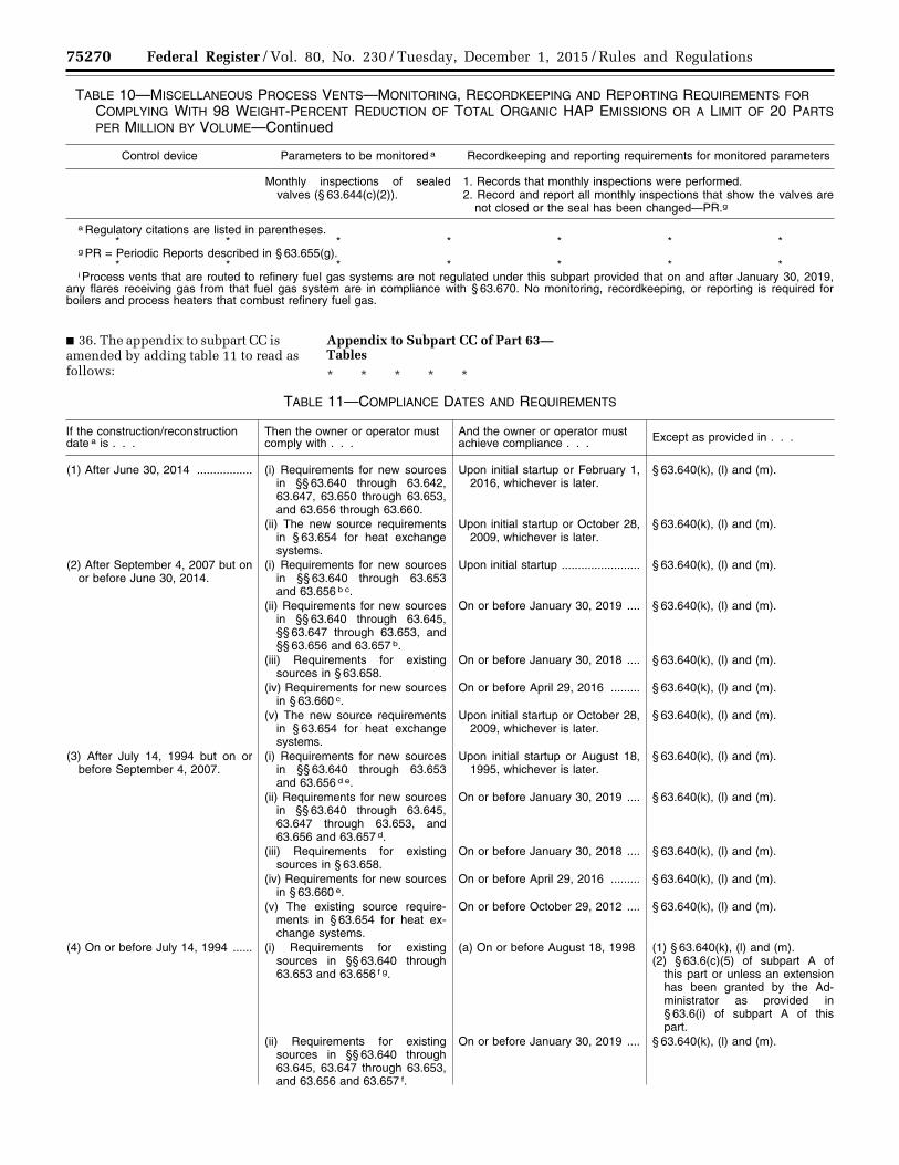
75270 Federal Register / Vol. 80, No. 230 / Tuesday, December 1, 2015 / Rules and Regulations
TABLE 10—MISCELLANEOUS PROCESS VENTS—MONITORING, RECORDKEEPING AND REPORTING REQUIREMENTS FOR COMPLYING WITH 98 WEIGHT-PERCENT REDUCTION OF TOTAL ORGANIC HAP EMISSIONS OR A LIMIT OF 20 PARTS PER MILLION BY VOLUME—Continued
Control device Parameters to be monitored a Recordkeeping and reporting requirements for monitored parameters
Monthly inspections of sealed valves (§ 63.644(c)(2)).
1. Records that monthly inspections were performed. 2. Record and report all monthly inspections that show the valves are
not closed or the seal has been changed—PR.g
a Regulatory citations are listed in parentheses. * * * * * * *
g PR = Periodic Reports described in § 63.655(g). * * * * * * *
i Process vents that are routed to refinery fuel gas systems are not regulated under this subpart provided that on and after January 30, 2019, any flares receiving gas from that fuel gas system are in compliance with § 63.670. No monitoring, recordkeeping, or reporting is required for boilers and process heaters that combust refinery fuel gas.
■ 36. The appendix to subpart CC is amended by adding table 11 to read as follows:
Appendix to Subpart CC of Part 63— Tables
* * * * *
TABLE 11—COMPLIANCE DATES AND REQUIREMENTS
If the construction/reconstruction date a is . . .
Then the owner or operator must comply with . . .
And the owner or operator must achieve compliance . . . Except as provided in . . .
(1) After June 30, 2014 ................. (i) Requirements for new sources in §§ 63.640 through 63.642, 63.647, 63.650 through 63.653, and 63.656 through 63.660.
Upon initial startup or February 1, 2016, whichever is later.
§ 63.640(k), (l) and (m).
(ii) The new source requirements in § 63.654 for heat exchange systems.
Upon initial startup or October 28, 2009, whichever is later.
§ 63.640(k), (l) and (m).
(2) After September 4, 2007 but on or before June 30, 2014.
(i) Requirements for new sources in §§ 63.640 through 63.653 and 63.656 b c.
Upon initial startup ........................ § 63.640(k), (l) and (m).
(ii) Requirements for new sources in §§ 63.640 through 63.645, §§ 63.647 through 63.653, and §§ 63.656 and 63.657 b.
On or before January 30, 2019 .... § 63.640(k), (l) and (m).
(iii) Requirements for existing sources in § 63.658.
On or before January 30, 2018 .... § 63.640(k), (l) and (m).
(iv) Requirements for new sources in § 63.660 c.
On or before April 29, 2016 ......... § 63.640(k), (l) and (m).
(v) The new source requirements in § 63.654 for heat exchange systems.
Upon initial startup or October 28, 2009, whichever is later.
§ 63.640(k), (l) and (m).
(3) After July 14, 1994 but on or before September 4, 2007.
(i) Requirements for new sources in §§ 63.640 through 63.653 and 63.656 d e.
Upon initial startup or August 18, 1995, whichever is later.
§ 63.640(k), (l) and (m).
(ii) Requirements for new sources in §§ 63.640 through 63.645, 63.647 through 63.653, and 63.656 and 63.657 d.
On or before January 30, 2019 .... § 63.640(k), (l) and (m).
(iii) Requirements for existing sources in § 63.658.
On or before January 30, 2018 .... § 63.640(k), (l) and (m).
(iv) Requirements for new sources in § 63.660 e.
On or before April 29, 2016 ......... § 63.640(k), (l) and (m).
(v) The existing source require-ments in § 63.654 for heat ex-change systems.
On or before October 29, 2012 .... § 63.640(k), (l) and (m).
(4) On or before July 14, 1994 ...... (i) Requirements for existing sources in §§ 63.640 through 63.653 and 63.656 f g.
(a) On or before August 18, 1998 (1) § 63.640(k), (l) and (m). (2) § 63.6(c)(5) of subpart A of
this part or unless an extension has been granted by the Ad-ministrator as provided in § 63.6(i) of subpart A of this part.
(ii) Requirements for existing sources in §§ 63.640 through 63.645, 63.647 through 63.653, and 63.656 and 63.657 f.
On or before January 30, 2019 .... § 63.640(k), (l) and (m).
VerDate Sep<11>2014 23:11 Nov 30, 2015 Jkt 238001 PO 00000 Frm 00094 Fmt 4701 Sfmt 4700 E:\FR\FM\01DER2.SGM 01DER2tkel
ley
on D
SK
3SP
TV
N1P
RO
D w
ith R
ULE
S2
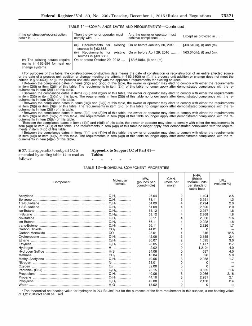
75271 Federal Register / Vol. 80, No. 230 / Tuesday, December 1, 2015 / Rules and Regulations
TABLE 11—COMPLIANCE DATES AND REQUIREMENTS—Continued
If the construction/reconstruction date a is . . .
Then the owner or operator must comply with . . .
And the owner or operator must achieve compliance . . . Except as provided in . . .
(iii) Requirements for existing sources in § 63.658.
On or before January 30, 2018 .... § 63.640(k), (l) and (m).
(iv) Requirements for existing sources in § 63.660 g.
On or before April 29, 2016 ......... § 63.640(k), (l) and (m).
(v) The existing source require-ments in § 63.654 for heat ex-change systems
On or before October 29, 2012 .... § 63.640(k), (l) and (m).
a For purposes of this table, the construction/reconstruction date means the date of construction or reconstruction of an entire affected source or the date of a process unit addition or change meeting the criteria in § 63.640(i) or (j). If a process unit addition or change does not meet the criteria in § 63.640(i) or (j), the process unit shall comply with the applicable requirements for existing sources.
b Between the compliance dates in items (2)(i) and (2)(ii) of this table, the owner or operator may elect to comply with either the requirements in item (2)(i) or item (2)(ii) of this table. The requirements in item (2)(i) of this table no longer apply after demonstrated compliance with the re-quirements in item (2)(ii) of this table.
c Between the compliance dates in items (2)(i) and (2)(iv) of this table, the owner or operator may elect to comply with either the requirements in item (2)(i) or item (2)(iv) of this table. The requirements in item (2)(i) of this table no longer apply after demonstrated compliance with the re-quirements in item (2)(iv) of this table.
d Between the compliance dates in items (3)(i) and (3)(ii) of this table, the owner or operator may elect to comply with either the requirements in item (3)(i) or item (3)(ii) of this table. The requirements in item (3)(i) of this table no longer apply after demonstrated compliance with the re-quirements in item (3)(ii) of this table.
e Between the compliance dates in items (3)(i) and (3)(iv) of this table, the owner or operator may elect to comply with either the requirements in item (3)(i) or item (3)(iv) of this table. The requirements in item (3)(i) of this table no longer apply after demonstrated compliance with the re-quirements in item (3)(iv) of this table.
f Between the compliance dates in items (4)(i) and (4)(ii) of this table, the owner or operator may elect to comply with either the requirements in item (4)(i) or item (4)(ii) of this table. The requirements in item (4)(i) of this table no longer apply after demonstrated compliance with the require-ments in item (4)(ii) of this table.
g Between the compliance dates in items (4)(i) and (4)(iv) of this table, the owner or operator may elect to comply with either the requirements in item (4)(i) or item (4)(iv) of this table. The requirements in item (4)(i) of this table no longer apply after demonstrated compliance with the re-quirements in item (4)(iv) of this table.
■ 37. The appendix to subpart CC is amended by adding table 12 to read as follows:
Appendix to Subpart CC of Part 63— Tables
* * * * *
TABLE 12—INDIVIDUAL COMPONENT PROPERTIES
Component Molecular formula
MWi (pounds per pound-mole)
CMNi (mole per
mole)
NHVi (British
thermal units per standard cubic foot)
LFLi (volume %)
Acetylene ............................................................................. C2H2 ............... 26.04 2 1,404 2.5 Benzene ............................................................................... C6H6 ............... 78.11 6 3,591 1.3 1,2-Butadiene ...................................................................... C4H6 ............... 54.09 4 2,794 2.0 1,3-Butadiene ...................................................................... C4H6 ............... 54.09 4 2,690 2.0 iso-Butane ............................................................................ C4H10 ............. 58.12 4 2,957 1.8 n-Butane .............................................................................. C4H10 ............. 58.12 4 2,968 1.8 cis-Butene ............................................................................ C4H8 ............... 56.11 4 2,830 1.6 iso-Butene ............................................................................ C4H8 ............... 56.11 4 2,928 1.8 trans-Butene ........................................................................ C4H8 ............... 56.11 4 2,826 1.7 Carbon Dioxide .................................................................... CO2 ................ 44.01 1 0 ∞ Carbon Monoxide ................................................................ CO ................. 28.01 1 316 12.5 Cyclopropane ....................................................................... C3H6 ............... 42.08 3 2,185 2.4 Ethane ................................................................................. C2H6 ............... 30.07 2 1,595 3.0 Ethylene ............................................................................... C2H4 ............... 28.05 2 1,477 2.7 Hydrogen ............................................................................. H2 ................... 2.02 0 1,212a 4.0 Hydrogen Sulfide ................................................................. H2S ................ 34.08 0 587 4.0 Methane ............................................................................... CH4 ................ 16.04 1 896 5.0 Methyl-Acetylene ................................................................. C3H4 ............... 40.06 3 2,088 1.7 Nitrogen ............................................................................... N2 ................... 28.01 0 0 ∞ Oxygen ................................................................................ O2 ................... 32.00 0 0 ∞ Pentane+ (C5+) ................................................................... C5H12 ............. 72.15 5 3,655 1.4 Propadiene .......................................................................... C3H4 ............... 40.06 3 2,066 2.16 Propane ............................................................................... C3H8 ............... 44.10 3 2,281 2.1 Propylene ............................................................................. C3H6 ............... 42.08 3 2,150 2.4 Water ................................................................................... H2O ................ 18.02 0 0 ∞
a The theoretical net heating value for hydrogen is 274 Btu/scf, but for the purposes of the flare requirement in this subpart, a net heating value of 1,212 Btu/scf shall be used.
VerDate Sep<11>2014 23:11 Nov 30, 2015 Jkt 238001 PO 00000 Frm 00095 Fmt 4701 Sfmt 4700 E:\FR\FM\01DER2.SGM 01DER2tkel
ley
on D
SK
3SP
TV
N1P
RO
D w
ith R
ULE
S2
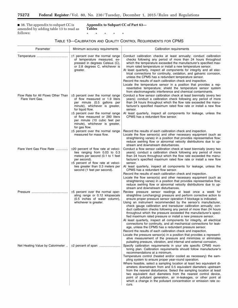
75272 Federal Register / Vol. 80, No. 230 / Tuesday, December 1, 2015 / Rules and Regulations
■ 38. The appendix to subpart CC is amended by adding table 13 to read as follows:
Appendix to Subpart CC of Part 63— Tables
* * * * *
TABLE 13—CALIBRATION AND QUALITY CONTROL REQUIREMENTS FOR CPMS
Parameter Minimum accuracy requirements Calibration requirements
Temperature .................................... ±1 percent over the normal range of temperature measured, ex-pressed in degrees Celsius (C), or 2.8 degrees C, whichever is greater.
Conduct calibration checks at least annually; conduct calibration checks following any period of more than 24 hours throughout which the temperature exceeded the manufacturer’s specified max-imum rated temperature or install a new temperature sensor.
At least quarterly, inspect all components for integrity and all elec-trical connections for continuity, oxidation, and galvanic corrosion, unless the CPMS has a redundant temperature sensor.
Record the results of each calibration check and inspection. Locate the temperature sensor in a position that provides a rep-
resentative temperature; shield the temperature sensor system from electromagnetic interference and chemical contaminants.
Flow Rate for All Flows Other Than Flare Vent Gas.
±5 percent over the normal range of flow measured or 1.9 liters per minute (0.5 gallons per minute), whichever is greater, for liquid flow.
Conduct a flow sensor calibration check at least biennially (every two years); conduct a calibration check following any period of more than 24 hours throughout which the flow rate exceeded the manu-facturer’s specified maximum rated flow rate or install a new flow sensor.
±5 percent over the normal range of flow measured or 280 liters per minute (10 cubic feet per minute), whichever is greater, for gas flow.
At least quarterly, inspect all components for leakage, unless the CPMS has a redundant flow sensor.
±5 percent over the normal range measured for mass flow.
Record the results of each calibration check and inspection. Locate the flow sensor(s) and other necessary equipment (such as
straightening vanes) in a position that provides representative flow; reduce swirling flow or abnormal velocity distributions due to up-stream and downstream disturbances.
Flare Vent Gas Flow Rate .............. ±20 percent of flow rate at veloci-ties ranging from 0.03 to 0.3 meters per second (0.1 to 1 feet per second).
±5 percent of flow rate at veloci-ties greater than 0.3 meters per second (1 feet per second).
Conduct a flow sensor calibration check at least biennially (every two years); conduct a calibration check following any period of more than 24 hours throughout which the flow rate exceeded the manu-facturer’s specified maximum rated flow rate or install a new flow sensor.
At least quarterly, inspect all components for leakage, unless the CPMS has a redundant flow sensor.
Record the results of each calibration check and inspection. Locate the flow sensor(s) and other necessary equipment (such as
straightening vanes) in a position that provides representative flow; reduce swirling flow or abnormal velocity distributions due to up-stream and downstream disturbances.
Pressure .......................................... ±5 percent over the normal oper-ating range or 0.12 kilopascals (0.5 inches of water column), whichever is greater.
Review pressure sensor readings at least once a week for straightline (unchanging) pressure and perform corrective action to ensure proper pressure sensor operation if blockage is indicated.
Using an instrument recommended by the sensor’s manufacturer, check gauge calibration and transducer calibration annually; con-duct calibration checks following any period of more than 24 hours throughout which the pressure exceeded the manufacturer’s speci-fied maximum rated pressure or install a new pressure sensor.
At least quarterly, inspect all components for integrity, all electrical connections for continuity, and all mechanical connections for leak-age, unless the CPMS has a redundant pressure sensor.
Record the results of each calibration check and inspection. Locate the pressure sensor(s) in a position that provides a represent-
ative measurement of the pressure and minimizes or eliminates pulsating pressure, vibration, and internal and external corrosion.
Net Heating Value by Calorimeter .. ±2 percent of span ........................ Specify calibration requirements in your site specific CPMS moni-toring plan. Calibration requirements should follow manufacturer’s recommendations at a minimum.
Temperature control (heated and/or cooled as necessary) the sam-pling system to ensure proper year-round operation.
Where feasible, select a sampling location at least two equivalent di-ameters downstream from and 0.5 equivalent diameters upstream from the nearest disturbance. Select the sampling location at least two equivalent duct diameters from the nearest control device, point of pollutant generation, air in-leakages, or other point at which a change in the pollutant concentration or emission rate oc-curs.
VerDate Sep<11>2014 23:11 Nov 30, 2015 Jkt 238001 PO 00000 Frm 00096 Fmt 4701 Sfmt 4700 E:\FR\FM\01DER2.SGM 01DER2tkel
ley
on D
SK
3SP
TV
N1P
RO
D w
ith R
ULE
S2

75273 Federal Register / Vol. 80, No. 230 / Tuesday, December 1, 2015 / Rules and Regulations
TABLE 13—CALIBRATION AND QUALITY CONTROL REQUIREMENTS FOR CPMS—Continued
Parameter Minimum accuracy requirements Calibration requirements
Net Heating Value by Gas Chro-matograph.
As specified in Performance Spec-ification 9 of 40 CFR part 60, appendix B
Follow the procedure in Performance Specification 9 of 40 CFR part 60, appendix B, except that a single daily mid-level calibration check can be used (rather than triplicate analysis), the multi-point calibration can be conducted quarterly (rather than monthly), and the sampling line temperature must be maintained at a minimum temperature of 60 °C (rather than 120 °C).
Hydrogen analyzer .......................... ±2 percent over the concentration measured or 0.1 volume per-cent, whichever is greater.
Specify calibration requirements in your site specific CPMS moni-toring plan. Calibration requirements should follow manufacturer’s recommendations at a minimum.
Select the sampling location at least two equivalent duct diameters from the nearest control device, point of pollutant generation, air in- leakages, or other point at which a change in the pollutant con-centration occurs.
Subpart UUU-—National Emission Standards for Hazardous Air Pollutants for Petroleum Refineries: Catalytic Cracking Units, Catalytic Reforming Units, and Sulfur Recovery Units
■ 39. Section 63.1562 is amended by revising paragraphs (b)(3) and (f)(5) to read as follows:
§ 63.1562 What parts of my plant are covered by this subpart? * * * * *
(b) * * * (3) The process vent or group of
process vents on Claus or other types of sulfur recovery plant units or the tail gas treatment units serving sulfur recovery plants that are associated with sulfur recovery. * * * * *
(f) * * * (5) Gaseous streams routed to a fuel
gas system, provided that on and after January 30, 2019, any flares receiving gas from the fuel gas system are subject to § 63.670. ■ 40. Section 63.1564 is amended by: ■ a. Revising paragraphs (a)(1) and (2); ■ b. Adding paragraph (a)(5); ■ c. Removing the equation following paragraph (b)(4)(ii) and adding it after paragraph (b)(4)(iii) introductory text; ■ d. Revising paragraphs (b)(2), (b)(4)(i) and (ii), and (b)(4)(iv); and ■ e. Adding paragraph (c)(5).
The revisions and additions read as follows:
§ 63.1564 What are my requirements for metal HAP emissions from catalytic cracking units?
(a) * * *
(1) Except as provided in paragraph (a)(5) of this section, meet each emission limitation in Table 1 of this subpart that applies to you. If your catalytic cracking unit is subject to the NSPS for PM in § 60.102 of this chapter or is subject to § 60.102a(b)(1) of this chapter, you must meet the emission limitations for NSPS units. If your catalytic cracking unit is not subject to the NSPS for PM, you can choose from the four options in paragraphs (a)(1)(i) through (vi) of this section:
(i) You can elect to comply with the NSPS for PM in § 60.102 of this chapter (Option 1a);
(ii) You can elect to comply with the NSPS for PM coke burn-off emission limit in § 60.102a(b)(1) of this chapter (Option 1b);
(iii) You can elect to comply with the NSPS for PM concentration limit in § 60.102a(b)(1) of this chapter (Option 1c);
(iv) You can elect to comply with the PM per coke burn-off emission limit in § 60.102a(b)(1) of this chapter (Option 2);
(v) You can elect to comply with the Nickel (Ni) lb/hr emission limit (Option 3); or
(vi) You can elect to comply with the Ni per coke burn-off emission limit (Option 4).
(2) Comply with each operating limit in Table 2 of this subpart that applies to you. When a specific control device may be monitored using more than one continuous parameter monitoring system, you may select the parameter with which you will comply. You must provide notice to the Administrator (or
other designated authority) if you elect to change the monitoring option. * * * * *
(5) During periods of startup, shutdown and hot standby, you can choose from the two options in paragraphs (a)(5)(i) and (ii) of this section:
(i) You can elect to comply with the requirements in paragraphs (a)(1) and (2) of this section, except catalytic cracking units controlled using a wet scrubber must maintain only the liquid to gas ratio operating limit (the pressure drop operating limit does not apply); or
(ii) You can elect to maintain the inlet velocity to the primary internal cyclones of the catalytic cracking unit catalyst regenerator at or above 20 feet per second.
(b) * * * (2) Conduct a performance test for
each catalytic cracking unit according to the requirements in § 63.1571 and under the conditions specified in Table 4 of this subpart. * * * * *
(4) * * * (i) If you elect Option 1b or Option 2
in paragraph (a)(1)(ii) or (iv) of this section, compute the PM emission rate (lb/1,000 lb of coke burn-off) for each run using Equations 1, 2, and 3 (if applicable) of this section and the site- specific opacity limit, if applicable, using Equation 4 of this section as follows:
Where:
Rc = Coke burn-off rate, kg/hr (lb/hr);
Qr = Volumetric flow rate of exhaust gas from catalyst regenerator before adding air or
gas streams. Example: You may measure upstream or downstream of an
VerDate Sep<11>2014 23:11 Nov 30, 2015 Jkt 238001 PO 00000 Frm 00097 Fmt 4701 Sfmt 4700 E:\FR\FM\01DER2.SGM 01DER2 ER
01D
E15
.018
</G
PH
>
tkel
ley
on D
SK
3SP
TV
N1P
RO
D w
ith R
ULE
S2
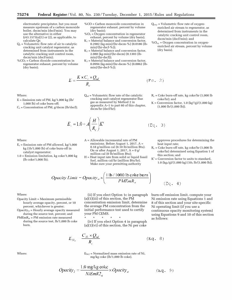
75274 Federal Register / Vol. 80, No. 230 / Tuesday, December 1, 2015 / Rules and Regulations
electrostatic precipitator, but you must measure upstream of a carbon monoxide boiler, dscm/min (dscf/min). You may use the alternative in either § 63.1573(a)(1) or (2), as applicable, to calculate Qr;
Qa = Volumetric flow rate of air to catalytic cracking unit catalyst regenerator, as determined from instruments in the catalytic cracking unit control room, dscm/min (dscf/min);
%CO2 = Carbon dioxide concentration in regenerator exhaust, percent by volume (dry basis);
%CO = Carbon monoxide concentration in regenerator exhaust, percent by volume (dry basis);
%O2 = Oxygen concentration in regenerator exhaust, percent by volume (dry basis);
K1 = Material balance and conversion factor, 0.2982 (kg-min)/(hr-dscm-%) (0.0186 (lb- min)/(hr-dscf-%));
K2 = Material balance and conversion factor, 2.088 (kg-min)/(hr-dscm) (0.1303 (lb- min)/(hr-dscf));
K3 = Material balance and conversion factor, 0.0994 (kg-min)/(hr-dscm-%) (0.0062 (lb- min)/(hr-dscf-%));
Qoxy = Volumetric flow rate of oxygen- enriched air stream to regenerator, as determined from instruments in the catalytic cracking unit control room, dscm/min (dscf/min); and
%Oxy = Oxygen concentration in oxygen- enriched air stream, percent by volume (dry basis).
Where:
E = Emission rate of PM, kg/1,000 kg (lb/ 1,000 lb) of coke burn-off;
Cs = Concentration of PM, g/dscm (lb/dscf);
Qsd = Volumetric flow rate of the catalytic cracking unit catalyst regenerator flue gas as measured by Method 2 in appendix A–1 to part 60 of this chapter, dscm/hr (dscf/hr);
Rc = Coke burn-off rate, kg coke/hr (1,000 lb coke/hr); and
K = Conversion factor, 1.0 (kg2/g)/(1,000 kg) (1,000 lb/(1,000 lb)).
Where:
Es = Emission rate of PM allowed, kg/1,000 kg (1b/1,000 lb) of coke burn-off in catalyst regenerator;
1.0 = Emission limitation, kg coke/1,000 kg (lb coke/1,000 lb);
A = Allowable incremental rate of PM emissions. Before August 1, 2017, A = 0.18 g/million cal (0.10 lb/million Btu). On or after August 1, 2017, A = 0 g/ million cal (0 lb/million Btu);
H = Heat input rate from solid or liquid fossil fuel, million cal/hr (million Btu/hr). Make sure your permitting authority
approves procedures for determining the heat input rate;
Rc = Coke burn-off rate, kg coke/hr (1,000 lb coke/hr) determined using Equation 1 of this section; and
K′ = Conversion factor to units to standard, 1.0 (kg2/g)/(1,000 kg) (103 lb/(1,000 lb)).
Where:
Opacity Limit = Maximum permissible hourly average opacity, percent, or 10 percent, whichever is greater;
Opacityst = Hourly average opacity measured during the source test, percent; and
PMEmRst = PM emission rate measured during the source test, lb/1,000 lb coke burn.
(ii) If you elect Option 1c in paragraph (a)(1)(iii) of this section, the PM concentration emission limit, determine the average PM concentration from the initial performance test used to certify your PM CEMS. * * * * *
(iv) If you elect Option 4 in paragraph (a)(1)(vi) of this section, the Ni per coke
burn-off emission limit, compute your Ni emission rate using Equations 1 and 8 of this section and your site-specific Ni operating limit (if you use a continuous opacity monitoring system) using Equations 9 and 10 of this section as follows:
Where: ENi2 = Normalized mass emission rate of Ni, mg/kg coke (lb/1,000 lb coke).
VerDate Sep<11>2014 23:11 Nov 30, 2015 Jkt 238001 PO 00000 Frm 00098 Fmt 4701 Sfmt 4725 E:\FR\FM\01DER2.SGM 01DER2 ER
01D
E15
.019
</G
PH
>E
R01
DE
15.0
20<
/GP
H>
ER
01D
E15
.021
</G
PH
>E
R01
DE
15.0
22<
/GP
H>
ER
01D
E15
.023
</G
PH
>
tkel
ley
on D
SK
3SP
TV
N1P
RO
D w
ith R
ULE
S2
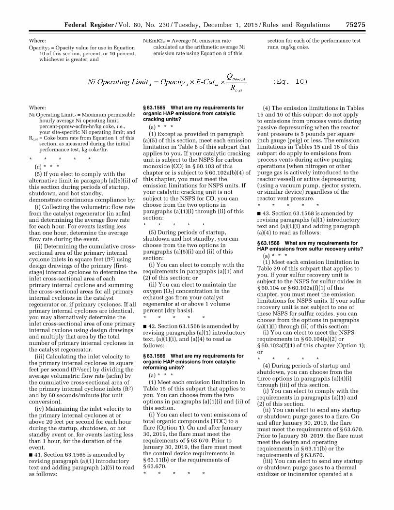
75275 Federal Register / Vol. 80, No. 230 / Tuesday, December 1, 2015 / Rules and Regulations
Where: Opacity2 = Opacity value for use in Equation
10 of this section, percent, or 10 percent, whichever is greater; and
NiEmR2st = Average Ni emission rate calculated as the arithmetic average Ni emission rate using Equation 8 of this
section for each of the performance test runs, mg/kg coke.
Where: Ni Operating Limit2 = Maximum permissible
hourly average Ni operating limit, percent-ppmw-acfm-hr/kg coke, i.e., your site-specific Ni operating limit; and
Rc,st = Coke burn rate from Equation 1 of this section, as measured during the initial performance test, kg coke/hr.
* * * * * (c) * * * (5) If you elect to comply with the
alternative limit in paragraph (a)(5)(ii) of this section during periods of startup, shutdown, and hot standby, demonstrate continuous compliance by:
(i) Collecting the volumetric flow rate from the catalyst regenerator (in acfm) and determining the average flow rate for each hour. For events lasting less than one hour, determine the average flow rate during the event.
(ii) Determining the cumulative cross- sectional area of the primary internal cyclone inlets in square feet (ft2) using design drawings of the primary (first- stage) internal cyclones to determine the inlet cross-sectional area of each primary internal cyclone and summing the cross-sectional areas for all primary internal cyclones in the catalyst regenerator or, if primary cyclones. If all primary internal cyclones are identical, you may alternatively determine the inlet cross-sectional area of one primary internal cyclone using design drawings and multiply that area by the total number of primary internal cyclones in the catalyst regenerator.
(iii) Calculating the inlet velocity to the primary internal cyclones in square feet per second (ft2/sec) by dividing the average volumetric flow rate (acfm) by the cumulative cross-sectional area of the primary internal cyclone inlets (ft2) and by 60 seconds/minute (for unit conversion).
(iv) Maintaining the inlet velocity to the primary internal cyclones at or above 20 feet per second for each hour during the startup, shutdown, or hot standby event or, for events lasting less than 1 hour, for the duration of the event. ■ 41. Section 63.1565 is amended by revising paragraph (a)(1) introductory text and adding paragraph (a)(5) to read as follows:
§ 63.1565 What are my requirements for organic HAP emissions from catalytic cracking units?
(a) * * * (1) Except as provided in paragraph
(a)(5) of this section, meet each emission limitation in Table 8 of this subpart that applies to you. If your catalytic cracking unit is subject to the NSPS for carbon monoxide (CO) in § 60.103 of this chapter or is subject to § 60.102a(b)(4) of this chapter, you must meet the emission limitations for NSPS units. If your catalytic cracking unit is not subject to the NSPS for CO, you can choose from the two options in paragraphs (a)(1)(i) through (ii) of this section: * * * * *
(5) During periods of startup, shutdown and hot standby, you can choose from the two options in paragraphs (a)(5)(i) and (ii) of this section:
(i) You can elect to comply with the requirements in paragraphs (a)(1) and (2) of this section; or
(ii) You can elect to maintain the oxygen (O2) concentration in the exhaust gas from your catalyst regenerator at or above 1 volume percent (dry basis). * * * * * ■ 42. Section 63.1566 is amended by revising paragraphs (a)(1) introductory text, (a)(1)(i), and (a)(4) to read as follows:
§ 63.1566 What are my requirements for organic HAP emissions from catalytic reforming units?
(a) * * * (1) Meet each emission limitation in
Table 15 of this subpart that applies to you. You can choose from the two options in paragraphs (a)(1)(i) and (ii) of this section.
(i) You can elect to vent emissions of total organic compounds (TOC) to a flare (Option 1). On and after January 30, 2019, the flare must meet the requirements of § 63.670. Prior to January 30, 2019, the flare must meet the control device requirements in § 63.11(b) or the requirements of § 63.670. * * * * *
(4) The emission limitations in Tables 15 and 16 of this subpart do not apply to emissions from process vents during passive depressuring when the reactor vent pressure is 5 pounds per square inch gauge (psig) or less. The emission limitations in Tables 15 and 16 of this subpart do apply to emissions from process vents during active purging operations (when nitrogen or other purge gas is actively introduced to the reactor vessel) or active depressuring (using a vacuum pump, ejector system, or similar device) regardless of the reactor vent pressure. * * * * * ■ 43. Section 63.1568 is amended by revising paragraphs (a)(1) introductory text and (a)(1)(i) and adding paragraph (a)(4) to read as follows:
§ 63.1568 What are my requirements for HAP emissions from sulfur recovery units?
(a) * * * (1) Meet each emission limitation in
Table 29 of this subpart that applies to you. If your sulfur recovery unit is subject to the NSPS for sulfur oxides in § 60.104 or § 60.102a(f)(1) of this chapter, you must meet the emission limitations for NSPS units. If your sulfur recovery unit is not subject to one of these NSPS for sulfur oxides, you can choose from the options in paragraphs (a)(1)(i) through (ii) of this section:
(i) You can elect to meet the NSPS requirements in § 60.104(a)(2) or § 60.102a(f)(1) of this chapter (Option 1); or * * * * *
(4) During periods of startup and shutdown, you can choose from the three options in paragraphs (a)(4)(i) through (iii) of this section.
(i) You can elect to comply with the requirements in paragraphs (a)(1) and (2) of this section.
(ii) You can elect to send any startup or shutdown purge gases to a flare. On and after January 30, 2019, the flare must meet the requirements of § 63.670. Prior to January 30, 2019, the flare must meet the design and operating requirements in § 63.11(b) or the requirements of § 63.670.
(iii) You can elect to send any startup or shutdown purge gases to a thermal oxidizer or incinerator operated at a
VerDate Sep<11>2014 23:11 Nov 30, 2015 Jkt 238001 PO 00000 Frm 00099 Fmt 4701 Sfmt 4700 E:\FR\FM\01DER2.SGM 01DER2 ER
01D
E15
.024
</G
PH
>
tkel
ley
on D
SK
3SP
TV
N1P
RO
D w
ith R
ULE
S2
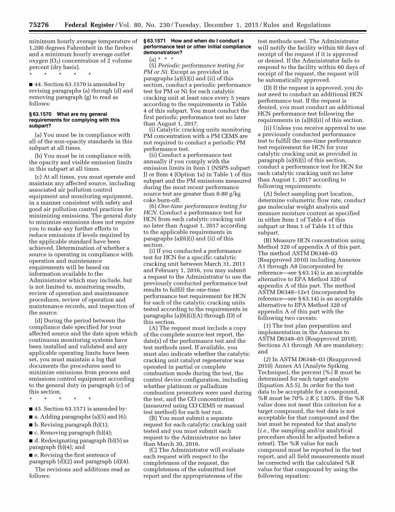
75276 Federal Register / Vol. 80, No. 230 / Tuesday, December 1, 2015 / Rules and Regulations
minimum hourly average temperature of 1,200 degrees Fahrenheit in the firebox and a minimum hourly average outlet oxygen (O2) concentration of 2 volume percent (dry basis). * * * * *
■ 44. Section 63.1570 is amended by revising paragraphs (a) through (d) and removing paragraph (g) to read as follows:
§ 63.1570 What are my general requirements for complying with this subpart?
(a) You must be in compliance with all of the non-opacity standards in this subpart at all times.
(b) You must be in compliance with the opacity and visible emission limits in this subpart at all times.
(c) At all times, you must operate and maintain any affected source, including associated air pollution control equipment and monitoring equipment, in a manner consistent with safety and good air pollution control practices for minimizing emissions. The general duty to minimize emissions does not require you to make any further efforts to reduce emissions if levels required by the applicable standard have been achieved. Determination of whether a source is operating in compliance with operation and maintenance requirements will be based on information available to the Administrator which may include, but is not limited to, monitoring results, review of operation and maintenance procedures, review of operation and maintenance records, and inspection of the source.
(d) During the period between the compliance date specified for your affected source and the date upon which continuous monitoring systems have been installed and validated and any applicable operating limits have been set, you must maintain a log that documents the procedures used to minimize emissions from process and emissions control equipment according to the general duty in paragraph (c) of this section. * * * * *
■ 45. Section 63.1571 is amended by: ■ a. Adding paragraphs (a)(5) and (6); ■ b. Revising paragraph (b)(1); ■ c. Removing paragraph (b)(4); ■ d. Redesignating paragraph (b)(5) as paragraph (b)(4); and ■ e. Revising the first sentence of paragraph (d)(2) and paragraph (d)(4).
The revisions and additions read as follows:
§ 63.1571 How and when do I conduct a performance test or other initial compliance demonstration?
(a) * * * (5) Periodic performance testing for
PM or Ni. Except as provided in paragraphs (a)(5)(i) and (ii) of this section, conduct a periodic performance test for PM or Ni for each catalytic cracking unit at least once every 5 years according to the requirements in Table 4 of this subpart. You must conduct the first periodic performance test no later than August 1, 2017.
(i) Catalytic cracking units monitoring PM concentration with a PM CEMS are not required to conduct a periodic PM performance test.
(ii) Conduct a performance test annually if you comply with the emission limits in Item 1 (NSPS subpart J) or Item 4 (Option 1a) in Table 1 of this subpart and the PM emissions measured during the most recent performance source test are greater than 0.80 g/kg coke burn-off.
(6) One-time performance testing for HCN. Conduct a performance test for HCN from each catalytic cracking unit no later than August 1, 2017 according to the applicable requirements in paragraphs (a)(6)(i) and (ii) of this section.
(i) If you conducted a performance test for HCN for a specific catalytic cracking unit between March 31, 2011 and February 1, 2016, you may submit a request to the Administrator to use the previously conducted performance test results to fulfill the one-time performance test requirement for HCN for each of the catalytic cracking units tested according to the requirements in paragraphs (a)(6)(i)(A) through (D) of this section.
(A) The request must include a copy of the complete source test report, the date(s) of the performance test and the test methods used. If available, you must also indicate whether the catalytic cracking unit catalyst regenerator was operated in partial or complete combustion mode during the test, the control device configuration, including whether platinum or palladium combustion promoters were used during the test, and the CO concentration (measured using CO CEMS or manual test method) for each test run.
(B) You must submit a separate request for each catalytic cracking unit tested and you must submit each request to the Administrator no later than March 30, 2016.
(C) The Administrator will evaluate each request with respect to the completeness of the request, the completeness of the submitted test report and the appropriateness of the
test methods used. The Administrator will notify the facility within 60 days of receipt of the request if it is approved or denied. If the Administrator fails to respond to the facility within 60 days of receipt of the request, the request will be automatically approved.
(D) If the request is approved, you do not need to conduct an additional HCN performance test. If the request is denied, you must conduct an additional HCN performance test following the requirements in (a)(6)(ii) of this section.
(ii) Unless you receive approval to use a previously conducted performance test to fulfill the one-time performance test requirement for HCN for your catalytic cracking unit as provided in paragraph (a)(6)(i) of this section, conduct a performance test for HCN for each catalytic cracking unit no later than August 1, 2017 according to following requirements:
(A) Select sampling port location, determine volumetric flow rate, conduct gas molecular weight analysis and measure moisture content as specified in either Item 1 of Table 4 of this subpart or Item 1 of Table 11 of this subpart.
(B) Measure HCN concentration using Method 320 of appendix A of this part. The method ASTM D6348–03 (Reapproved 2010) including Annexes A1 through A8 (incorporated by reference—see § 63.14) is an acceptable alternative to EPA Method 320 of appendix A of this part. The method ASTM D6348–12e1 (incorporated by reference—see § 63.14) is an acceptable alternative to EPA Method 320 of appendix A of this part with the following two caveats:
(1) The test plan preparation and implementation in the Annexes to ASTM D6348–03 (Reapproved 2010), Sections A1 through A8 are mandatory; and
(2) In ASTM D6348–03 (Reapproved 2010) Annex A5 (Analyte Spiking Technique), the percent (%) R must be determined for each target analyte (Equation A5.5). In order for the test data to be acceptable for a compound, %R must be 70% ≥ R ≤ 130%. If the %R value does not meet this criterion for a target compound, the test data is not acceptable for that compound and the test must be repeated for that analyte (i.e., the sampling and/or analytical procedure should be adjusted before a retest). The %R value for each compound must be reported in the test report, and all field measurements must be corrected with the calculated %R value for that compound by using the following equation:
VerDate Sep<11>2014 23:11 Nov 30, 2015 Jkt 238001 PO 00000 Frm 00100 Fmt 4701 Sfmt 4700 E:\FR\FM\01DER2.SGM 01DER2tkel
ley
on D
SK
3SP
TV
N1P
RO
D w
ith R
ULE
S2
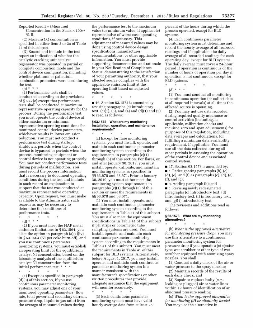
75277 Federal Register / Vol. 80, No. 230 / Tuesday, December 1, 2015 / Rules and Regulations
Reported Result = (Measured Concentration in the Stack × 100÷/ % R.
(C) Measure CO concentration as specified in either Item 2 or 3a of Table 11 of this subpart.
(D) Record and include in the test report an indication of whether the catalytic cracking unit catalyst regenerator was operated in partial or complete combustion mode and the control device configuration, including whether platinum or palladium combustion promoters were used during the test.
(b) * * * (1) Performance tests shall be
conducted according to the provisions of § 63.7(e) except that performance tests shall be conducted at maximum representative operating capacity for the process. During the performance test, you must operate the control device at either maximum or minimum representative operating conditions for monitored control device parameters, whichever results in lower emission reduction. You must not conduct a performance test during startup, shutdown, periods when the control device is bypassed or periods when the process, monitoring equipment or control device is not operating properly. You may not conduct performance tests during periods of malfunction. You must record the process information that is necessary to document operating conditions during the test and include in such record an explanation to support that the test was conducted at maximum representative operating capacity. Upon request, you must make available to the Administrator such records as may be necessary to determine the conditions of performance tests. * * * * *
(d) * * * (2) If you must meet the HAP metal
emission limitations in § 63.1564, you elect the option in paragraph (a)(1)(iv) in § 63.1564 (Ni per coke burn-off), and you use continuous parameter monitoring systems, you must establish an operating limit for the equilibrium catalyst Ni concentration based on the laboratory analysis of the equilibrium catalyst Ni concentration from the initial performance test. * * * * * * * *
(4) Except as specified in paragraph (d)(3) of this section, if you use continuous parameter monitoring systems, you may adjust one of your monitored operating parameters (flow rate, total power and secondary current, pressure drop, liquid-to-gas ratio) from the average of measured values during
the performance test to the maximum value (or minimum value, if applicable) representative of worst-case operating conditions, if necessary. This adjustment of measured values may be done using control device design specifications, manufacturer recommendations, or other applicable information. You must provide supporting documentation and rationale in your Notification of Compliance Status, demonstrating to the satisfaction of your permitting authority, that your affected source complies with the applicable emission limit at the operating limit based on adjusted values. * * * * * ■ 46. Section 63.1572 is amended by revising paragraphs (c) introductory text, (c)(1), (3), and (4) and (d)(1) and (2) to read as follows:
§ 63.1572 What are my monitoring installation, operation, and maintenance requirements?
* * * * * (c) Except for flare monitoring
systems, you must install, operate, and maintain each continuous parameter monitoring system according to the requirements in paragraphs (c)(1) through (5) of this section. For flares, on and after January 30, 2019, you must install, operate, calibrate, and maintain monitoring systems as specified in §§ 63.670 and 63.671. Prior to January 30, 2019, you must either meet the monitoring system requirements in paragraphs (c)(1) through (5) of this section or meet the requirements in §§ 63.670 and 63.671.
(1) You must install, operate, and maintain each continuous parameter monitoring system according to the requirements in Table 41 of this subpart. You must also meet the equipment specifications in Table 41 of this subpart if pH strips or colormetric tube sampling systems are used. You must install, operate, and maintain each continuous parameter monitoring system according to the requirements in Table 41 of this subpart. You must meet the requirements in Table 41 of this subpart for BLD systems. Alternatively, before August 1, 2017, you may install, operate, and maintain each continuous parameter monitoring system in a manner consistent with the manufacturer’s specifications or other written procedures that provide adequate assurance that the equipment will monitor accurately. * * * * *
(3) Each continuous parameter monitoring system must have valid hourly average data from at least 75
percent of the hours during which the process operated, except for BLD systems.
(4) Each continuous parameter monitoring system must determine and record the hourly average of all recorded readings and if applicable, the daily average of all recorded readings for each operating day, except for BLD systems. The daily average must cover a 24-hour period if operation is continuous or the number of hours of operation per day if operation is not continuous, except for BLD systems. * * * * *
(d) * * * (1) You must conduct all monitoring
in continuous operation (or collect data at all required intervals) at all times the affected source is operating.
(2) You may not use data recorded during required quality assurance or control activities (including, as applicable, calibration checks and required zero and span adjustments) for purposes of this regulation, including data averages and calculations, for fulfilling a minimum data availability requirement, if applicable. You must use all the data collected during all other periods in assessing the operation of the control device and associated control system. ■ 47. Section 63.1573 is amended by: ■ a. Redesignating paragraphs (b), (c), (d), (e), and (f) as paragraphs (c), (d), (e), (f), and (g); ■ b. Adding paragraph (b); and ■ c. Revising newly redesignated paragraphs (c) introductory text, (d) introductory text, (f) introductory text, and (g)(1) introductory text.
The revisions and additions read as follows:
§ 63.1573 What are my monitoring alternatives?
* * * * * (b) What is the approved alternative
for monitoring pressure drop? You may use this alternative to a continuous parameter monitoring system for pressure drop if you operate a jet ejector type wet scrubber or other type of wet scrubber equipped with atomizing spray nozzles. You shall:
(1) Conduct a daily check of the air or water pressure to the spray nozzles;
(2) Maintain records of the results of each daily check; and
(3) Repair or replace faulty (e.g., leaking or plugged) air or water lines within 12 hours of identification of an abnormal pressure reading.
(c) What is the approved alternative for monitoring pH or alkalinity levels? You may use the alternative in
VerDate Sep<11>2014 23:11 Nov 30, 2015 Jkt 238001 PO 00000 Frm 00101 Fmt 4701 Sfmt 4700 E:\FR\FM\01DER2.SGM 01DER2tkel
ley
on D
SK
3SP
TV
N1P
RO
D w
ith R
ULE
S2
75278 Federal Register / Vol. 80, No. 230 / Tuesday, December 1, 2015 / Rules and Regulations
paragraph (c)(1) or (2) of this section for a catalytic reforming unit. * * * * *
(d) Can I use another type of monitoring system? You may use an automated data compression system. An automated data compression system does not record monitored operating parameter values at a set frequency (e.g., once every hour) but records all values that meet set criteria for variation from previously recorded values. You must maintain a record of the description of the monitoring system and data recording system, including the criteria used to determine which monitored values are recorded and retained, the method for calculating daily averages, and a demonstration that the system meets all of the criteria in paragraphs (d)(1) through (5) of this section: * * * * *
(f) How do I request to monitor alternative parameters? You must submit a request for review and approval or disapproval to the Administrator. The request must include the information in paragraphs (f)(1) through (5) of this section. * * * * *
(g) * * * (1) You may request alternative
monitoring requirements according to the procedures in this paragraph if you meet each of the conditions in paragraphs (g)(1)(i) through (iii) of this section: * * * * * ■ 48. Section 63.1574 is amended by revising paragraphs (a)(3) introductory text and (f)(1) to read as follows:
§ 63.1574 What notifications must I submit and when?
(a) * * * (3) If you are required to conduct an
initial performance test, performance evaluation, design evaluation, opacity observation, visible emission observation, or other initial compliance demonstration, you must submit a notification of compliance status according to § 63.9(h)(2)(ii). You can submit this information in an operating permit application, in an amendment to an operating permit application, in a separate submission, or in any combination. In a State with an approved operating permit program where delegation of authority under section 112(l) of the CAA has not been requested or approved, you must provide a duplicate notification to the applicable Regional Administrator. If the required information has been submitted previously, you do not have to provide a separate notification of compliance status. Just refer to the
earlier submissions instead of duplicating and resubmitting the previously submitted information. * * * * *
(f) * * * (1) You must submit the plan to your
permitting authority for review and approval along with your notification of compliance status. While you do not have to include the entire plan in your permit under part 70 or 71 of this chapter, you must include the duty to prepare and implement the plan as an applicable requirement in your part 70 or 71 operating permit. You must submit any changes to your permitting authority for review and approval and comply with the plan as submitted until the change is approved. * * * * * ■ 49. Section 63.1575 is amended by: ■ a. Revising paragraphs (d) introductory text and (d)(1) and (2); ■ b. Adding paragraph (d)(4); ■ c. Revising paragraph (e) introductory text; ■ d. Removing and reserving paragraph (e)(1); ■ e. Revising paragraphs (e)(4) and (6) and (f)(1) and (2); ■ f. Removing and reserving paragraph (h); and ■ g. Adding paragraph (k).
The revisions and additions read as follows:
§ 63.1575 What reports must I submit and when? * * * * *
(d) For each deviation from an emission limitation and for each deviation from the requirements for work practice standards that occurs at an affected source where you are not using a continuous opacity monitoring system or a continuous emission monitoring system to comply with the emission limitation or work practice standard in this subpart, the semiannual compliance report must contain the information in paragraphs (c)(1) through (3) of this section and the information in paragraphs (d)(1) through (4) of this section.
(1) The total operating time of each affected source during the reporting period and identification of the sources for which there was a deviation.
(2) Information on the number, date, time, duration, and cause of deviations (including unknown cause, if applicable). * * * * *
(4) The applicable operating limit or work practice standard from which you deviated and either the parameter monitor reading during the deviation or a description of how you deviated from the work practice standard.
(e) For each deviation from an emission limitation occurring at an affected source where you are using a continuous opacity monitoring system or a continuous emission monitoring system to comply with the emission limitation, you must include the information in paragraphs (c)(1) through (3) of this section, in paragraphs (d)(1) through (3) of this section, and in paragraphs (e)(2) through (13) of this section. * * * * *
(4) An estimate of the quantity of each regulated pollutant emitted over the emission limit during the deviation, and a description of the method used to estimate the emissions. * * * * *
(6) A breakdown of the total duration of the deviations during the reporting period and into those that are due to control equipment problems, process problems, other known causes, and other unknown causes. * * * * *
(f) * * * (1) You must include the information
in paragraph (f)(1)(i) or (ii) of this section, if applicable.
(i) If you are complying with paragraph (k)(1) of this section, a summary of the results of any performance test done during the reporting period on any affected unit. Results of the performance test include the identification of the source tested, the date of the test, the percentage of emissions reduction or outlet pollutant concentration reduction (whichever is needed to determine compliance) for each run and for the average of all runs, and the values of the monitored operating parameters.
(ii) If you are not complying with paragraph (k)(1) of this section, a copy of any performance test done during the reporting period on any affected unit. The report may be included in the next semiannual compliance report. The copy must include a complete report for each test method used for a particular kind of emission point tested. For additional tests performed for a similar emission point using the same method, you must submit the results and any other information required, but a complete test report is not required. A complete test report contains a brief process description; a simplified flow diagram showing affected processes, control equipment, and sampling point locations; sampling site data; description of sampling and analysis procedures and any modifications to standard procedures; quality assurance procedures; record of operating conditions during the test; record of
VerDate Sep<11>2014 23:11 Nov 30, 2015 Jkt 238001 PO 00000 Frm 00102 Fmt 4701 Sfmt 4700 E:\FR\FM\01DER2.SGM 01DER2tkel
ley
on D
SK
3SP
TV
N1P
RO
D w
ith R
ULE
S2
75279 Federal Register / Vol. 80, No. 230 / Tuesday, December 1, 2015 / Rules and Regulations
preparation of standards; record of calibrations; raw data sheets for field sampling; raw data sheets for field and laboratory analyses; documentation of calculations; and any other information required by the test method.
(2) Any requested change in the applicability of an emission standard (e.g., you want to change from the PM standard to the Ni standard for catalytic cracking units or from the HCl concentration standard to percent reduction for catalytic reforming units) in your compliance report. You must include all information and data necessary to demonstrate compliance with the new emission standard selected and any other associated requirements. * * * * *
(k) Electronic submittal of performance test and CEMS performance evaluation data. For performance tests or CEMS performance evaluations conducted on and after February 1, 2016, if required to submit the results of a performance test or CEMS performance evaluation, you must submit the results according to the procedures in paragraphs (k)(1) and (2) of this section.
(1) Within 60 days after the date of completing each performance test as required by this subpart, you must submit the results of the performance tests following the procedure specified in either paragraph (k)(1)(i) or (ii) of this section.
(i) For data collected using test methods supported by the EPA’s Electronic Reporting Tool (ERT) as listed on the EPA’s ERT Web site (http://www.epa.gov/ttn/chief/ert/index.html) at the time of the test, you must submit the results of the performance test to the EPA via the Compliance and Emissions Data Reporting Interface (CEDRI). (CEDRI can be accessed through the EPA’s Central Data Exchange (CDX) (https://cdx.epa.gov/).) Performance test data must be submitted in a file format generated through use of the EPA’s ERT or an alternate electronic file format consistent with the extensible markup language (XML) schema listed on the EPA’s ERT Web site. If you claim that some of the performance test information being submitted is confidential business information (CBI), you must submit a complete file generated through the use of the EPA’s ERT or an alternate electronic file consistent with the XML schema listed on the EPA’s ERT Web site, including information claimed to be CBI, on a compact disc, flash drive or other commonly used electronic storage
media to the EPA. The electronic storage media must be clearly marked as CBI and mailed to U.S. EPA/OAQPS/CORE CBI Office, Attention: Group Leader, Measurement Policy Group, MD C404– 02, 4930 Old Page Rd., Durham, NC 27703. The same ERT or alternate file with the CBI omitted must be submitted to the EPA via the EPA’s CDX as described earlier in this paragraph (k)(1)(i).
(ii) For data collected using test methods that are not supported by the EPA’s ERT as listed on the EPA’s ERT Web site at the time of the test, you must submit the results of the performance test to the Administrator at the appropriate address listed in § 63.13.
(2) Within 60 days after the date of completing each CEMS performance evaluation required by § 63.1571(a) and (b), you must submit the results of the performance evaluation following the procedure specified in either paragraph (k)(2)(i) or (ii) of this section.
(i) For performance evaluations of continuous monitoring systems measuring relative accuracy test audit (RATA) pollutants that are supported by the EPA’s ERT as listed on the EPA’s ERT Web site at the time of the evaluation, you must submit the results of the performance evaluation to the EPA via the CEDRI. (CEDRI is accessed through the EPA’s CDX.) Performance evaluation data must be submitted in a file format generated through the use of the EPA’s ERT or an alternate file format consistent with the XML schema listed on the EPA’s ERT Web site. If you claim that some of the performance evaluation information being submitted is CBI, you must submit a complete file generated through the use of the EPA’s ERT or an alternate electronic file consistent with the XML schema listed on the EPA’s ERT Web site, including information claimed to be CBI, on a compact disc, flash drive or other commonly used electronic storage media to the EPA. The electronic storage media must be clearly marked as CBI and mailed to U.S. EPA/ OAQPS/CORE CBI Office, Attention: Group Leader, Measurement Policy Group, MD C404–02, 4930 Old Page Rd., Durham, NC 27703. The same ERT or alternate file with the CBI omitted must be submitted to the EPA via the EPA’s CDX as described earlier in this paragraph (k)(2)(i).
(ii) For any performance evaluations of continuous monitoring systems measuring RATA pollutants that are not supported by the EPA’s ERT as listed on the EPA’s ERT Web site at the time of the evaluation, you must submit the results of the performance evaluation to the Administrator at the appropriate address listed in § 63.13.
■ 50. Section 63.1576 is amended by revising paragraphs (a)(2) and (b)(3) and (5) to read as follows:
§ 63.1576 What records must I keep, in what form, and for how long?
(a) * * * (2) The records specified in
paragraphs (a)(2)(i) through (iv) of this section.
(i) Record the date, time, and duration of each startup and/or shutdown period, recording the periods when the affected source was subject to the standard applicable to startup and shutdown.
(ii) In the event that an affected unit fails to meet an applicable standard, record the number of failures. For each failure record the date, time and duration of each failure.
(iii) For each failure to meet an applicable standard, record and retain a list of the affected sources or equipment, an estimate of the volume of each regulated pollutant emitted over any emission limit and a description of the method used to estimate the emissions.
(iv) Record actions taken to minimize emissions in accordance with § 63.1570(c) and any corrective actions taken to return the affected unit to its normal or usual manner of operation. * * * * *
(b) * * * (3) The performance evaluation plan
as described in § 63.8(d)(2) for the life of the affected source or until the affected source is no longer subject to the provisions of this part, to be made available for inspection, upon request, by the Administrator. If the performance evaluation plan is revised, you must keep previous (i.e., superseded) versions of the performance evaluation plan on record to be made available for inspection, upon request, by the Administrator, for a period of 5 years after each revision to the plan. The program of corrective action should be included in the plan required under § 63.8(d)(2). * * * * *
(5) Records of the date and time that each deviation started and stopped. * * * * * ■ 51. Section 63.1579 is amended by: ■ a. Revising the introductory text; ■ b. Adding, in alphabetical order, a new definition of ‘‘Hot standby’’; and ■ c. Revising the definitions of ‘‘Deviation’’ and ‘‘PM’’.
The revisions read as follows:
§ 63.1579 What definitions apply to this subpart?
Terms used in this subpart are defined in the Clean Air Act (CAA), in 40 CFR 63.2, the General Provisions of
VerDate Sep<11>2014 23:11 Nov 30, 2015 Jkt 238001 PO 00000 Frm 00103 Fmt 4701 Sfmt 4700 E:\FR\FM\01DER2.SGM 01DER2tkel
ley
on D
SK
3SP
TV
N1P
RO
D w
ith R
ULE
S2
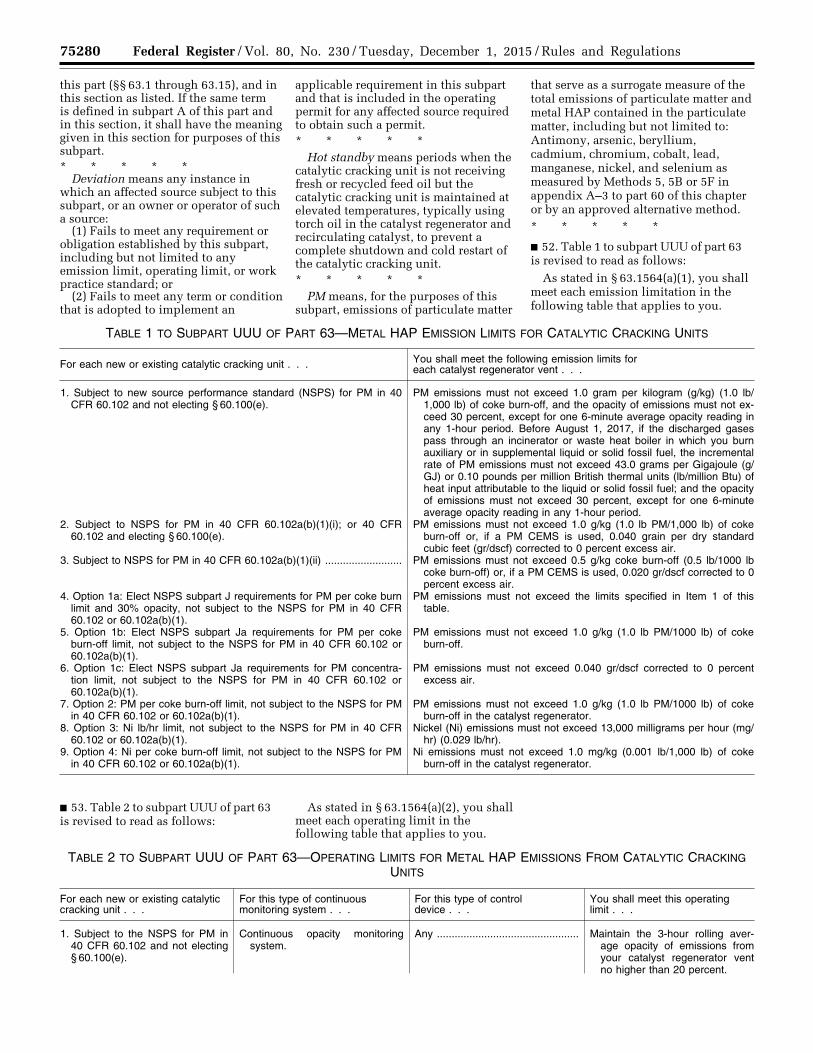
75280 Federal Register / Vol. 80, No. 230 / Tuesday, December 1, 2015 / Rules and Regulations
this part (§§ 63.1 through 63.15), and in this section as listed. If the same term is defined in subpart A of this part and in this section, it shall have the meaning given in this section for purposes of this subpart. * * * * *
Deviation means any instance in which an affected source subject to this subpart, or an owner or operator of such a source:
(1) Fails to meet any requirement or obligation established by this subpart, including but not limited to any emission limit, operating limit, or work practice standard; or
(2) Fails to meet any term or condition that is adopted to implement an
applicable requirement in this subpart and that is included in the operating permit for any affected source required to obtain such a permit. * * * * *
Hot standby means periods when the catalytic cracking unit is not receiving fresh or recycled feed oil but the catalytic cracking unit is maintained at elevated temperatures, typically using torch oil in the catalyst regenerator and recirculating catalyst, to prevent a complete shutdown and cold restart of the catalytic cracking unit. * * * * *
PM means, for the purposes of this subpart, emissions of particulate matter
that serve as a surrogate measure of the total emissions of particulate matter and metal HAP contained in the particulate matter, including but not limited to: Antimony, arsenic, beryllium, cadmium, chromium, cobalt, lead, manganese, nickel, and selenium as measured by Methods 5, 5B or 5F in appendix A–3 to part 60 of this chapter or by an approved alternative method. * * * * *
■ 52. Table 1 to subpart UUU of part 63 is revised to read as follows:
As stated in § 63.1564(a)(1), you shall meet each emission limitation in the following table that applies to you.
TABLE 1 TO SUBPART UUU OF PART 63—METAL HAP EMISSION LIMITS FOR CATALYTIC CRACKING UNITS
For each new or existing catalytic cracking unit . . . You shall meet the following emission limits for each catalyst regenerator vent . . .
1. Subject to new source performance standard (NSPS) for PM in 40 CFR 60.102 and not electing § 60.100(e).
PM emissions must not exceed 1.0 gram per kilogram (g/kg) (1.0 lb/1,000 lb) of coke burn-off, and the opacity of emissions must not ex-ceed 30 percent, except for one 6-minute average opacity reading in any 1-hour period. Before August 1, 2017, if the discharged gases pass through an incinerator or waste heat boiler in which you burn auxiliary or in supplemental liquid or solid fossil fuel, the incremental rate of PM emissions must not exceed 43.0 grams per Gigajoule (g/GJ) or 0.10 pounds per million British thermal units (lb/million Btu) of heat input attributable to the liquid or solid fossil fuel; and the opacity of emissions must not exceed 30 percent, except for one 6-minute average opacity reading in any 1-hour period.
2. Subject to NSPS for PM in 40 CFR 60.102a(b)(1)(i); or 40 CFR 60.102 and electing § 60.100(e).
PM emissions must not exceed 1.0 g/kg (1.0 lb PM/1,000 lb) of coke burn-off or, if a PM CEMS is used, 0.040 grain per dry standard cubic feet (gr/dscf) corrected to 0 percent excess air.
3. Subject to NSPS for PM in 40 CFR 60.102a(b)(1)(ii) .......................... PM emissions must not exceed 0.5 g/kg coke burn-off (0.5 lb/1000 lb coke burn-off) or, if a PM CEMS is used, 0.020 gr/dscf corrected to 0 percent excess air.
4. Option 1a: Elect NSPS subpart J requirements for PM per coke burn limit and 30% opacity, not subject to the NSPS for PM in 40 CFR 60.102 or 60.102a(b)(1).
PM emissions must not exceed the limits specified in Item 1 of this table.
5. Option 1b: Elect NSPS subpart Ja requirements for PM per coke burn-off limit, not subject to the NSPS for PM in 40 CFR 60.102 or 60.102a(b)(1).
PM emissions must not exceed 1.0 g/kg (1.0 lb PM/1000 lb) of coke burn-off.
6. Option 1c: Elect NSPS subpart Ja requirements for PM concentra-tion limit, not subject to the NSPS for PM in 40 CFR 60.102 or 60.102a(b)(1).
PM emissions must not exceed 0.040 gr/dscf corrected to 0 percent excess air.
7. Option 2: PM per coke burn-off limit, not subject to the NSPS for PM in 40 CFR 60.102 or 60.102a(b)(1).
PM emissions must not exceed 1.0 g/kg (1.0 lb PM/1000 lb) of coke burn-off in the catalyst regenerator.
8. Option 3: Ni lb/hr limit, not subject to the NSPS for PM in 40 CFR 60.102 or 60.102a(b)(1).
Nickel (Ni) emissions must not exceed 13,000 milligrams per hour (mg/hr) (0.029 lb/hr).
9. Option 4: Ni per coke burn-off limit, not subject to the NSPS for PM in 40 CFR 60.102 or 60.102a(b)(1).
Ni emissions must not exceed 1.0 mg/kg (0.001 lb/1,000 lb) of coke burn-off in the catalyst regenerator.
■ 53. Table 2 to subpart UUU of part 63 is revised to read as follows:
As stated in § 63.1564(a)(2), you shall meet each operating limit in the following table that applies to you.
TABLE 2 TO SUBPART UUU OF PART 63—OPERATING LIMITS FOR METAL HAP EMISSIONS FROM CATALYTIC CRACKING UNITS
For each new or existing catalytic cracking unit . . .
For this type of continuous monitoring system . . .
For this type of control device . . .
You shall meet this operating limit . . .
1. Subject to the NSPS for PM in 40 CFR 60.102 and not electing § 60.100(e).
Continuous opacity monitoring system.
Any ................................................ Maintain the 3-hour rolling aver-age opacity of emissions from your catalyst regenerator vent no higher than 20 percent.
VerDate Sep<11>2014 23:11 Nov 30, 2015 Jkt 238001 PO 00000 Frm 00104 Fmt 4701 Sfmt 4700 E:\FR\FM\01DER2.SGM 01DER2tkel
ley
on D
SK
3SP
TV
N1P
RO
D w
ith R
ULE
S2

75281 Federal Register / Vol. 80, No. 230 / Tuesday, December 1, 2015 / Rules and Regulations
TABLE 2 TO SUBPART UUU OF PART 63—OPERATING LIMITS FOR METAL HAP EMISSIONS FROM CATALYTIC CRACKING UNITS—Continued
For each new or existing catalytic cracking unit . . .
For this type of continuous monitoring system . . .
For this type of control device . . .
You shall meet this operating limit . . .
2. Subject to NSPS for PM in 40 CFR 60.102a(b)(1)(i) or electing § 60.100(e).
a. PM CEMS ................................. Any ................................................ Not applicable.
b. Continuous opacity monitoring system used to comply with a site-specific opacity limit.
Cyclone or electrostatic precipi-tator.
Maintain the 3-hour rolling aver-age opacity of emissions from your catalyst regenerator vent no higher than the site-specific opacity limit established during the performance test.
c. Continuous parameter moni-toring systems.
Electrostatic precipitator ............... i. Maintain the daily average coke burn-off rate or daily average flow rate no higher than the limit established in the perform-ance test.
ii. Maintain the 3-hour rolling aver-age total power and secondary current above the limit estab-lished in the performance test.
d. Continuous parameter moni-toring systems.
Wet scrubber ................................ i. Maintain the 3-hour rolling aver-age liquid-to-gas ratio above the limit established in the per-formance test.
ii. Except for periods of startup, shutdown, and hot standby, maintain the 3-hour rolling aver-age pressure drop above the limit established in the perform-ance test.1
e. Bag leak detection (BLD) sys-tem.
Fabric filter .................................... Maintain particulate loading below the BLD alarm set point estab-lished in the initial adjustment of the BLD system or allowable seasonal adjustments.
3. Subject to NSPS for PM in 40 CFR 60.102a(b)(1)(ii).
Any ................................................ Any ................................................ The applicable operating limits in Item 2 of this table.
4. Option 1a: Elect NSPS subpart J requirements for PM per coke burn limit, not subject to the NSPS for PM in 40 CFR 60.102 or 60.102a(b)(1).
Any ................................................ Any ................................................ See Item 1 of this table.
5. Option 1b: Elect NSPS subpart Ja requirements for PM per coke burn-off limit, not subject to the NSPS for PM in 40 CFR 60.102 or 60.102a(b)(1).
Any ................................................ Any ................................................ The applicable operating limits in Item 2.b, 2.c, 2.d, and 2.e of this table.
6. Option 1c: Elect NSPS subpart Ja requirements for PM con-centration limit, not subject to the NSPS for PM in 40 CFR 60.102 or 60.102a(b)(1).
PM CEMS ..................................... Any ................................................ Not applicable.
7. Option 2: PM per coke burn-off limit not subject to the NSPS for PM in 40 CFR 60.102 or 60.102a(b)(1).
a. Continuous opacity monitoring system used to comply with a site-specific opacity limit.
Cyclone, fabric filter, or electro-static precipitator.
See Item 2.b of this table. Alter-natively, before August 1, 2017, you may maintain the hourly average opacity of emissions from your catalyst generator vent no higher than the site- specific opacity limit established during the performance test.
b. Continuous parameter moni-toring systems.
i. Electrostatic precipitator ............ (1) See Item 2.c.i of this table. (2) See item 2.c.ii of this table. Al-
ternatively, before August 1, 2017, you may maintain the daily average voltage and sec-ondary current above the limit established in the performance test.
VerDate Sep<11>2014 23:11 Nov 30, 2015 Jkt 238001 PO 00000 Frm 00105 Fmt 4701 Sfmt 4700 E:\FR\FM\01DER2.SGM 01DER2tkel
ley
on D
SK
3SP
TV
N1P
RO
D w
ith R
ULE
S2

75282 Federal Register / Vol. 80, No. 230 / Tuesday, December 1, 2015 / Rules and Regulations
TABLE 2 TO SUBPART UUU OF PART 63—OPERATING LIMITS FOR METAL HAP EMISSIONS FROM CATALYTIC CRACKING UNITS—Continued
For each new or existing catalytic cracking unit . . .
For this type of continuous monitoring system . . .
For this type of control device . . .
You shall meet this operating limit . . .
ii. Wet scrubber ............................ (1) See Item 2.d.i of this table. Al-ternatively, before August 1, 2017, you may maintain the daily average liquid-to-gas ratio above the limit established in the performance test.
(2) See Item 2.d.ii of the table. Al-ternatively, before August 1, 2017, you may maintain the daily average pressure drop above the limit established in the performance test (not appli-cable to a wet scrubber of the non-venturi jet-ejector design).
c. Bag leak detection (BLD) sys-tem.
Fabric filter .................................... See item 2.e of this table.
8. Option 3: Ni lb/hr limit not sub-ject to the NSPS for PM in 40 CFR 60.102.
a. Continuous opacity monitoring system.
Cyclone, fabric filter, or electro-static precipitator.
Maintain the 3-hour rolling aver-age Ni operating value no high-er than the limit established during the performance test. Al-ternatively, before August 1, 2017, you may maintain the daily average Ni operating value no higher than the limit established during the perform-ance test.
b. Continuous parameter moni-toring systems.
i. Electrostatic precipitator ............ (1) See Item 2.c.i of this table. (2) Maintain the monthly rolling
average of the equilibrium cata-lyst Ni concentration no higher than the limit established during the performance test.
(3) See Item 2.c.ii of this table. Al-ternatively, before August 1, 2017, you may maintain the daily average voltage and sec-ondary current (or total power input) above the established during the performance test.
ii. Wet scrubber ............................ (1) Maintain the monthly rolling average of the equilibrium cata-lyst Ni concentration no higher than the limit established during the performance test.
(2) See Item 2.d.i of this table. Al-ternatively, before August 1, 2017, you may maintain the daily average liquid-to-gas ratio above the limit established dur-ing the performance test.
(3) See Item 2.d.ii of this table. Al-ternatively, before August 1, 2017, you may maintain the daily average pressure drop above the limit established dur-ing the performance test (not applicable to a non-venturi wet scrubber of the jet-ejector de-sign).
c. Bag leak detection (BLD) sys-tem.
Fabric filter .................................... See item 2.e of this table.
VerDate Sep<11>2014 23:11 Nov 30, 2015 Jkt 238001 PO 00000 Frm 00106 Fmt 4701 Sfmt 4700 E:\FR\FM\01DER2.SGM 01DER2tkel
ley
on D
SK
3SP
TV
N1P
RO
D w
ith R
ULE
S2
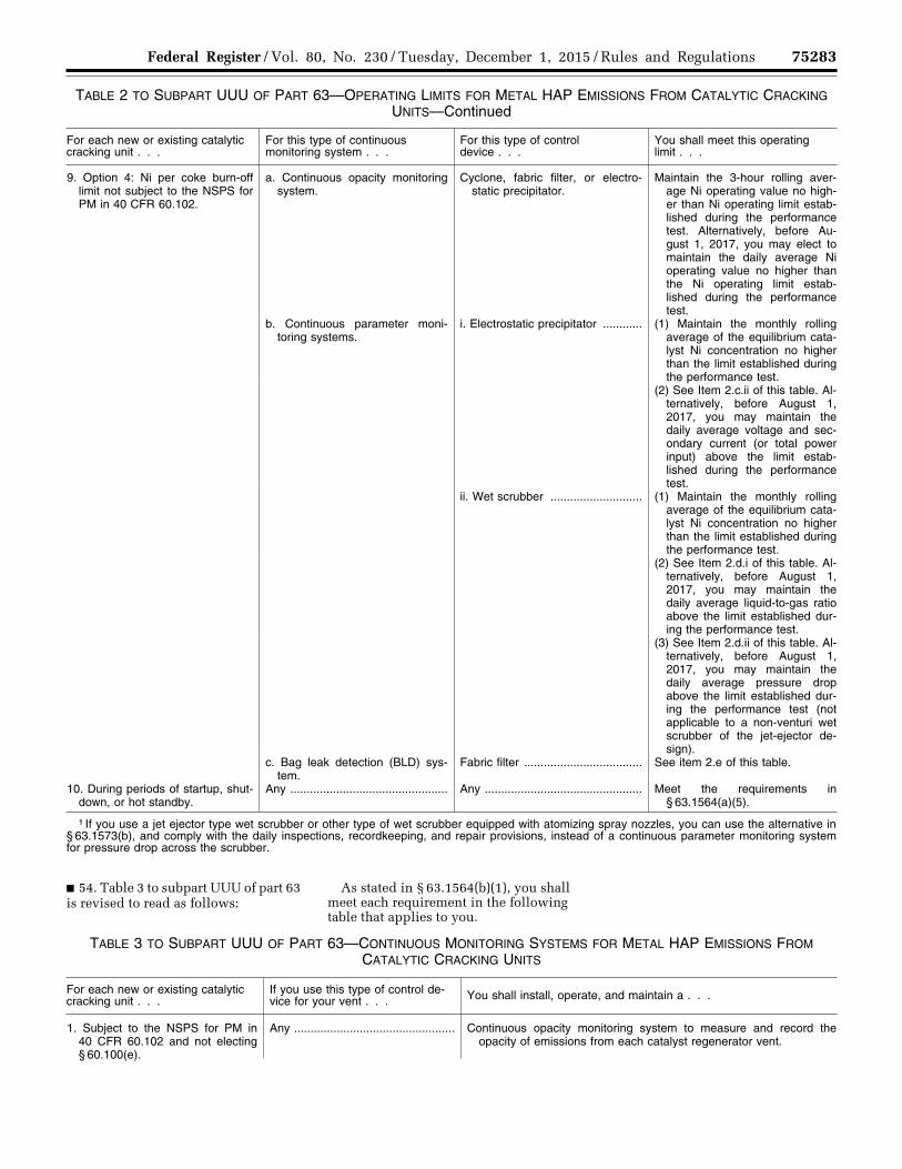
75283 Federal Register / Vol. 80, No. 230 / Tuesday, December 1, 2015 / Rules and Regulations
TABLE 2 TO SUBPART UUU OF PART 63—OPERATING LIMITS FOR METAL HAP EMISSIONS FROM CATALYTIC CRACKING UNITS—Continued
For each new or existing catalytic cracking unit . . .
For this type of continuous monitoring system . . .
For this type of control device . . .
You shall meet this operating limit . . .
9. Option 4: Ni per coke burn-off limit not subject to the NSPS for PM in 40 CFR 60.102.
a. Continuous opacity monitoring system.
Cyclone, fabric filter, or electro-static precipitator.
Maintain the 3-hour rolling aver-age Ni operating value no high-er than Ni operating limit estab-lished during the performance test. Alternatively, before Au-gust 1, 2017, you may elect to maintain the daily average Ni operating value no higher than the Ni operating limit estab-lished during the performance test.
b. Continuous parameter moni-toring systems.
i. Electrostatic precipitator ............ (1) Maintain the monthly rolling average of the equilibrium cata-lyst Ni concentration no higher than the limit established during the performance test.
(2) See Item 2.c.ii of this table. Al-ternatively, before August 1, 2017, you may maintain the daily average voltage and sec-ondary current (or total power input) above the limit estab-lished during the performance test.
ii. Wet scrubber ............................ (1) Maintain the monthly rolling average of the equilibrium cata-lyst Ni concentration no higher than the limit established during the performance test.
(2) See Item 2.d.i of this table. Al-ternatively, before August 1, 2017, you may maintain the daily average liquid-to-gas ratio above the limit established dur-ing the performance test.
(3) See Item 2.d.ii of this table. Al-ternatively, before August 1, 2017, you may maintain the daily average pressure drop above the limit established dur-ing the performance test (not applicable to a non-venturi wet scrubber of the jet-ejector de-sign).
c. Bag leak detection (BLD) sys-tem.
Fabric filter .................................... See item 2.e of this table.
10. During periods of startup, shut-down, or hot standby.
Any ................................................ Any ................................................ Meet the requirements in § 63.1564(a)(5).
1 If you use a jet ejector type wet scrubber or other type of wet scrubber equipped with atomizing spray nozzles, you can use the alternative in § 63.1573(b), and comply with the daily inspections, recordkeeping, and repair provisions, instead of a continuous parameter monitoring system for pressure drop across the scrubber.
■ 54. Table 3 to subpart UUU of part 63 is revised to read as follows:
As stated in § 63.1564(b)(1), you shall meet each requirement in the following table that applies to you.
TABLE 3 TO SUBPART UUU OF PART 63—CONTINUOUS MONITORING SYSTEMS FOR METAL HAP EMISSIONS FROM CATALYTIC CRACKING UNITS
For each new or existing catalytic cracking unit . . .
If you use this type of control de-vice for your vent . . . You shall install, operate, and maintain a . . .
1. Subject to the NSPS for PM in 40 CFR 60.102 and not electing § 60.100(e).
Any ................................................. Continuous opacity monitoring system to measure and record the opacity of emissions from each catalyst regenerator vent.
VerDate Sep<11>2014 23:11 Nov 30, 2015 Jkt 238001 PO 00000 Frm 00107 Fmt 4701 Sfmt 4700 E:\FR\FM\01DER2.SGM 01DER2tkel
ley
on D
SK
3SP
TV
N1P
RO
D w
ith R
ULE
S2
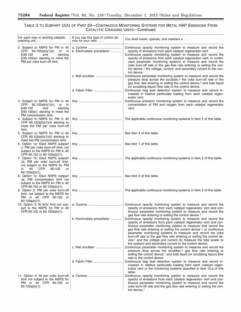
75284 Federal Register / Vol. 80, No. 230 / Tuesday, December 1, 2015 / Rules and Regulations
TABLE 3 TO SUBPART UUU OF PART 63—CONTINUOUS MONITORING SYSTEMS FOR METAL HAP EMISSIONS FROM CATALYTIC CRACKING UNITS—Continued
For each new or existing catalytic cracking unit . . .
If you use this type of control de-vice for your vent . . . You shall install, operate, and maintain a . . .
2. Subject to NSPS for PM in 40 CFR 60.102a(b)(1)(i); or in § 60.102 and electing § 60.100(e); electing to meet the PM per coke burn-off limit.
a. Cyclone ......................................b. Electrostatic precipitator ............
Continuous opacity monitoring system to measure and record the opacity of emissions from each catalyst regenerator vent.
Continuous opacity monitoring system to measure and record the opacity of emissions from each catalyst regenerator vent; or contin-uous parameter monitoring systems to measure and record the coke burn-off rate or the gas flow rate entering or exiting the con-trol device,1 the voltage, current, and secondary current to the con-trol device.
c. Wet scrubber ............................. Continuous parameter monitoring system to measure and record the pressure drop across the scrubber,2 the coke burn-off rate or the gas flow rate entering or exiting the control device,3 and total liquid (or scrubbing liquor) flow rate to the control device.
d. Fabric Filter ............................... Continuous bag leak detection system to measure and record in-creases in relative particulate loading from each catalyst regen-erator vent.
3. Subject to NSPS for PM in 40 CFR 60.102a(b)(1)(i); or in § 60.102 and electing § 60.100(e); electing to meet the PM concentration limit.
Any ................................................. Continuous emission monitoring system to measure and record the concentration of PM and oxygen from each catalyst regenerator vent.
4. Subject to NSPS for PM in 40 CFR 60.102a(b)(1)(ii) electing to meet the PM per coke burn-off limit.
Any ................................................. The applicable continuous monitoring systems in item 2 of this table.
5. Subject to NSPS for PM in 40 CFR 60.102a(b)(1)(ii) electing to meet the PM concentration limit.
Any ................................................. See item 3 of this table.
6. Option 1a: Elect NSPS subpart J, PM per coke burn-off limit, not subject to the NSPS for PM in 40 CFR 60.102 or 60.120a(b)(1).
Any ................................................. See item 1 of this table.
7. Option 1b: Elect NSPS subpart Ja, PM per coke burn-off limit, not subject to the NSPS for PM in 40 CFR 60.102 or 60.120a(b)(1).
Any ................................................. The applicable continuous monitoring systems in item 2 of this table.
8. Option 1c: Elect NSPS subpart Ja, PM concentration limit not subject to the NSPS for PM in 40 CFR 60.102 or 60.120a(b)(1).
Any ................................................. See item 3 of this table.
9. Option 2: PM per coke burn-off limit, not subject to the NSPS for PM in 40 CFR 60.102 or 60.120a(b)(1).
Any ................................................. The applicable continuous monitoring systems in item 2 of this table.
10. Option 3: Ni lb/hr limit not sub-ject to the NSPS for PM in 40 CFR 60.102 or 60.102a(b)(1).
a. Cyclone ...................................... Continuous opacity monitoring system to measure and record the opacity of emissions from each catalyst regenerator vent and con-tinuous parameter monitoring system to measure and record the gas flow rate entering or exiting the control device.1
b. Electrostatic precipitator ............ Continuous opacity monitoring system to measure and record the opacity of emissions from each catalyst regenerator vent and con-tinuous parameter monitoring system to measure and record the gas flow rate entering or exiting the control device 1; or continuous parameter monitoring systems to measure and record the coke burn-off rate or the gas flow rate entering or exiting the control de-vice 1 and the voltage and current (to measure the total power to the system) and secondary current to the control device.
c. Wet scrubber ............................. Continuous parameter monitoring system to measure and record the pressure drop across the scrubber,2 gas flow rate entering or exiting the control device,1 and total liquid (or scrubbing liquor) flow rate to the control device.
d. Fabric Filter ............................... Continuous bag leak detection system to measure and record in-creases in relative particulate loading from each catalyst regen-erator vent or the monitoring systems specified in item 10.a of this table.
11. Option 4: Ni per coke burn-off limit not subject to the NSPS for PM in 40 CFR 60.102 or 60.102a(b)(1).
a. Cyclone ...................................... Continuous opacity monitoring system to measure and record the opacity of emissions from each catalyst regenerator vent and con-tinuous parameter monitoring system to measure and record the coke burn-off rate and the gas flow rate entering or exiting the con-trol device.1
VerDate Sep<11>2014 23:11 Nov 30, 2015 Jkt 238001 PO 00000 Frm 00108 Fmt 4701 Sfmt 4700 E:\FR\FM\01DER2.SGM 01DER2tkel
ley
on D
SK
3SP
TV
N1P
RO
D w
ith R
ULE
S2
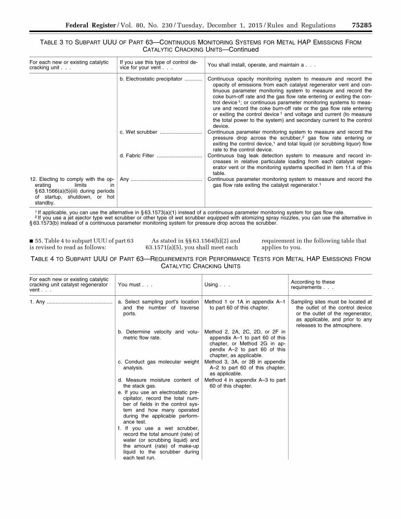
75285 Federal Register / Vol. 80, No. 230 / Tuesday, December 1, 2015 / Rules and Regulations
TABLE 3 TO SUBPART UUU OF PART 63—CONTINUOUS MONITORING SYSTEMS FOR METAL HAP EMISSIONS FROM CATALYTIC CRACKING UNITS—Continued
For each new or existing catalytic cracking unit . . .
If you use this type of control de-vice for your vent . . . You shall install, operate, and maintain a . . .
b. Electrostatic precipitator ............ Continuous opacity monitoring system to measure and record the opacity of emissions from each catalyst regenerator vent and con-tinuous parameter monitoring system to measure and record the coke burn-off rate and the gas flow rate entering or exiting the con-trol device 1; or continuous parameter monitoring systems to meas-ure and record the coke burn-off rate or the gas flow rate entering or exiting the control device 1 and voltage and current (to measure the total power to the system) and secondary current to the control device.
c. Wet scrubber ............................. Continuous parameter monitoring system to measure and record the pressure drop across the scrubber,2 gas flow rate entering or exiting the control device,1 and total liquid (or scrubbing liquor) flow rate to the control device.
d. Fabric Filter ............................... Continuous bag leak detection system to measure and record in-creases in relative particulate loading from each catalyst regen-erator vent or the monitoring systems specified in item 11.a of this table.
12. Electing to comply with the op-erating limits in § 63.1566(a)(5)(iii) during periods of startup, shutdown, or hot standby.
Any ................................................. Continuous parameter monitoring system to measure and record the gas flow rate exiting the catalyst regenerator.1
1 If applicable, you can use the alternative in § 63.1573(a)(1) instead of a continuous parameter monitoring system for gas flow rate. 2 If you use a jet ejector type wet scrubber or other type of wet scrubber equipped with atomizing spray nozzles, you can use the alternative in
§ 63.1573(b) instead of a continuous parameter monitoring system for pressure drop across the scrubber.
■ 55. Table 4 to subpart UUU of part 63 is revised to read as follows:
As stated in §§ 63.1564(b)(2) and 63.1571(a)(5), you shall meet each
requirement in the following table that applies to you.
TABLE 4 TO SUBPART UUU OF PART 63—REQUIREMENTS FOR PERFORMANCE TESTS FOR METAL HAP EMISSIONS FROM CATALYTIC CRACKING UNITS
For each new or existing catalytic cracking unit catalyst regenerator vent . . .
You must . . . Using . . . According to these requirements . . .
1. Any ............................................. a. Select sampling port’s location and the number of traverse ports.
Method 1 or 1A in appendix A–1 to part 60 of this chapter.
Sampling sites must be located at the outlet of the control device or the outlet of the regenerator, as applicable, and prior to any releases to the atmosphere.
b. Determine velocity and volu-metric flow rate.
Method 2, 2A, 2C, 2D, or 2F in appendix A–1 to part 60 of this chapter, or Method 2G in ap-pendix A–2 to part 60 of this chapter, as applicable.
c. Conduct gas molecular weight analysis.
Method 3, 3A, or 3B in appendix A–2 to part 60 of this chapter, as applicable.
d. Measure moisture content of the stack gas.
Method 4 in appendix A–3 to part 60 of this chapter.
e. If you use an electrostatic pre-cipitator, record the total num-ber of fields in the control sys-tem and how many operated during the applicable perform-ance test.
f. If you use a wet scrubber, record the total amount (rate) of water (or scrubbing liquid) and the amount (rate) of make-up liquid to the scrubber during each test run.
VerDate Sep<11>2014 23:11 Nov 30, 2015 Jkt 238001 PO 00000 Frm 00109 Fmt 4701 Sfmt 4700 E:\FR\FM\01DER2.SGM 01DER2tkel
ley
on D
SK
3SP
TV
N1P
RO
D w
ith R
ULE
S2
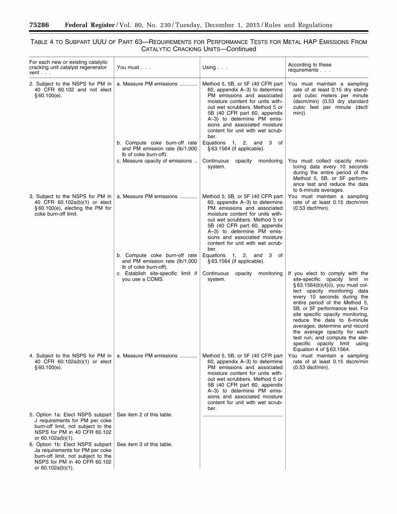
75286 Federal Register / Vol. 80, No. 230 / Tuesday, December 1, 2015 / Rules and Regulations
TABLE 4 TO SUBPART UUU OF PART 63—REQUIREMENTS FOR PERFORMANCE TESTS FOR METAL HAP EMISSIONS FROM CATALYTIC CRACKING UNITS—Continued
For each new or existing catalytic cracking unit catalyst regenerator vent . . .
You must . . . Using . . . According to these requirements . . .
2. Subject to the NSPS for PM in 40 CFR 60.102 and not elect § 60.100(e).
a. Measure PM emissions ............ Method 5, 5B, or 5F (40 CFR part 60, appendix A–3) to determine PM emissions and associated moisture content for units with-out wet scrubbers. Method 5 or 5B (40 CFR part 60, appendix A–3) to determine PM emis-sions and associated moisture content for unit with wet scrub-ber.
You must maintain a sampling rate of at least 0.15 dry stand-ard cubic meters per minute (dscm/min) (0.53 dry standard cubic feet per minute (dscf/min)).
b. Compute coke burn-off rate and PM emission rate (lb/1,000 lb of coke burn-off).
Equations 1, 2, and 3 of § 63.1564 (if applicable).
c. Measure opacity of emissions .. Continuous opacity monitoring system.
You must collect opacity moni-toring data every 10 seconds during the entire period of the Method 5, 5B, or 5F perform-ance test and reduce the data to 6-minute averages.
3. Subject to the NSPS for PM in 40 CFR 60.102a(b)(1) or elect § 60.100(e), electing the PM for coke burn-off limit.
a. Measure PM emissions ............ Method 5, 5B, or 5F (40 CFR part 60, appendix A–3) to determine PM emissions and associated moisture content for units with-out wet scrubbers. Method 5 or 5B (40 CFR part 60, appendix A–3) to determine PM emis-sions and associated moisture content for unit with wet scrub-ber.
You must maintain a sampling rate of at least 0.15 dscm/min (0.53 dscf/min).
b. Compute coke burn-off rate and PM emission rate (lb/1,000 lb of coke burn-off).
Equations 1, 2, and 3 of § 63.1564 (if applicable).
c. Establish site-specific limit if you use a COMS.
Continuous opacity monitoring system.
If you elect to comply with the site-specific opacity limit in § 63.1564(b)(4)(i), you must col-lect opacity monitoring data every 10 seconds during the entire period of the Method 5, 5B, or 5F performance test. For site specific opacity monitoring, reduce the data to 6-minute averages; determine and record the average opacity for each test run; and compute the site- specific opacity limit using Equation 4 of § 63.1564.
4. Subject to the NSPS for PM in 40 CFR 60.102a(b)(1) or elect § 60.100(e).
a. Measure PM emissions ............ Method 5, 5B, or 5F (40 CFR part 60, appendix A–3) to determine PM emissions and associated moisture content for units with-out wet scrubbers. Method 5 or 5B (40 CFR part 60, appendix A–3) to determine PM emis-sions and associated moisture content for unit with wet scrub-ber.
You must maintain a sampling rate of at least 0.15 dscm/min (0.53 dscf/min).
5. Option 1a: Elect NSPS subpart J requirements for PM per coke burn-off limit, not subject to the NSPS for PM in 40 CFR 60.102 or 60.102a(b)(1).
See item 2 of this table. .......................................................
6. Option 1b: Elect NSPS subpart Ja requirements for PM per coke burn-off limit, not subject to the NSPS for PM in 40 CFR 60.102 or 60.102a(b)(1).
See item 3 of this table.
VerDate Sep<11>2014 23:11 Nov 30, 2015 Jkt 238001 PO 00000 Frm 00110 Fmt 4701 Sfmt 4700 E:\FR\FM\01DER2.SGM 01DER2tkel
ley
on D
SK
3SP
TV
N1P
RO
D w
ith R
ULE
S2
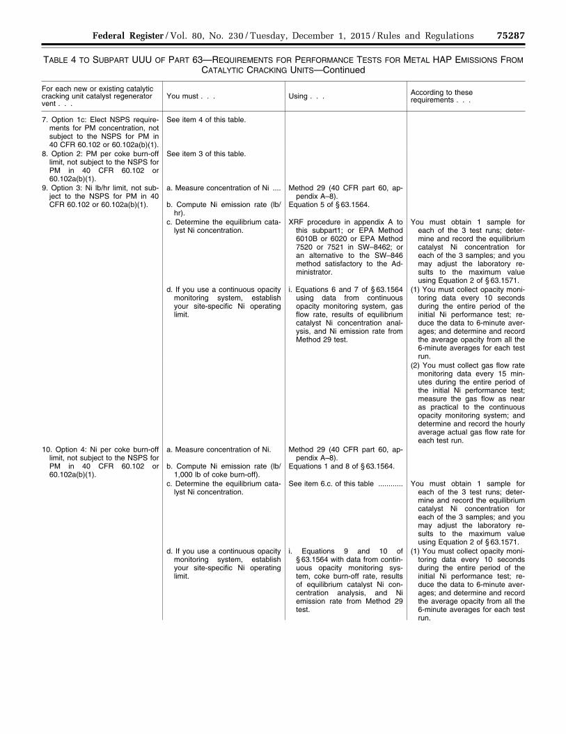
75287 Federal Register / Vol. 80, No. 230 / Tuesday, December 1, 2015 / Rules and Regulations
TABLE 4 TO SUBPART UUU OF PART 63—REQUIREMENTS FOR PERFORMANCE TESTS FOR METAL HAP EMISSIONS FROM CATALYTIC CRACKING UNITS—Continued
For each new or existing catalytic cracking unit catalyst regenerator vent . . .
You must . . . Using . . . According to these requirements . . .
7. Option 1c: Elect NSPS require-ments for PM concentration, not subject to the NSPS for PM in 40 CFR 60.102 or 60.102a(b)(1).
See item 4 of this table.
8. Option 2: PM per coke burn-off limit, not subject to the NSPS for PM in 40 CFR 60.102 or 60.102a(b)(1).
See item 3 of this table.
9. Option 3: Ni lb/hr limit, not sub-ject to the NSPS for PM in 40 CFR 60.102 or 60.102a(b)(1).
a. Measure concentration of Ni ....
b. Compute Ni emission rate (lb/hr).
Method 29 (40 CFR part 60, ap-pendix A–8).
Equation 5 of § 63.1564.
c. Determine the equilibrium cata-lyst Ni concentration.
XRF procedure in appendix A to this subpart1; or EPA Method 6010B or 6020 or EPA Method 7520 or 7521 in SW–8462; or an alternative to the SW–846 method satisfactory to the Ad-ministrator.
You must obtain 1 sample for each of the 3 test runs; deter-mine and record the equilibrium catalyst Ni concentration for each of the 3 samples; and you may adjust the laboratory re-sults to the maximum value using Equation 2 of § 63.1571.
d. If you use a continuous opacity monitoring system, establish your site-specific Ni operating limit.
i. Equations 6 and 7 of § 63.1564 using data from continuous opacity monitoring system, gas flow rate, results of equilibrium catalyst Ni concentration anal-ysis, and Ni emission rate from Method 29 test.
(1) You must collect opacity moni-toring data every 10 seconds during the entire period of the initial Ni performance test; re-duce the data to 6-minute aver-ages; and determine and record the average opacity from all the 6-minute averages for each test run.
(2) You must collect gas flow rate monitoring data every 15 min-utes during the entire period of the initial Ni performance test; measure the gas flow as near as practical to the continuous opacity monitoring system; and determine and record the hourly average actual gas flow rate for each test run.
10. Option 4: Ni per coke burn-off limit, not subject to the NSPS for PM in 40 CFR 60.102 or 60.102a(b)(1).
a. Measure concentration of Ni.
b. Compute Ni emission rate (lb/1,000 lb of coke burn-off).
Method 29 (40 CFR part 60, ap-pendix A–8).
Equations 1 and 8 of § 63.1564.
c. Determine the equilibrium cata-lyst Ni concentration.
See item 6.c. of this table ............ You must obtain 1 sample for each of the 3 test runs; deter-mine and record the equilibrium catalyst Ni concentration for each of the 3 samples; and you may adjust the laboratory re-sults to the maximum value using Equation 2 of § 63.1571.
d. If you use a continuous opacity monitoring system, establish your site-specific Ni operating limit.
i. Equations 9 and 10 of § 63.1564 with data from contin-uous opacity monitoring sys-tem, coke burn-off rate, results of equilibrium catalyst Ni con-centration analysis, and Ni emission rate from Method 29 test.
(1) You must collect opacity moni-toring data every 10 seconds during the entire period of the initial Ni performance test; re-duce the data to 6-minute aver-ages; and determine and record the average opacity from all the 6-minute averages for each test run.
VerDate Sep<11>2014 23:11 Nov 30, 2015 Jkt 238001 PO 00000 Frm 00111 Fmt 4701 Sfmt 4700 E:\FR\FM\01DER2.SGM 01DER2tkel
ley
on D
SK
3SP
TV
N1P
RO
D w
ith R
ULE
S2
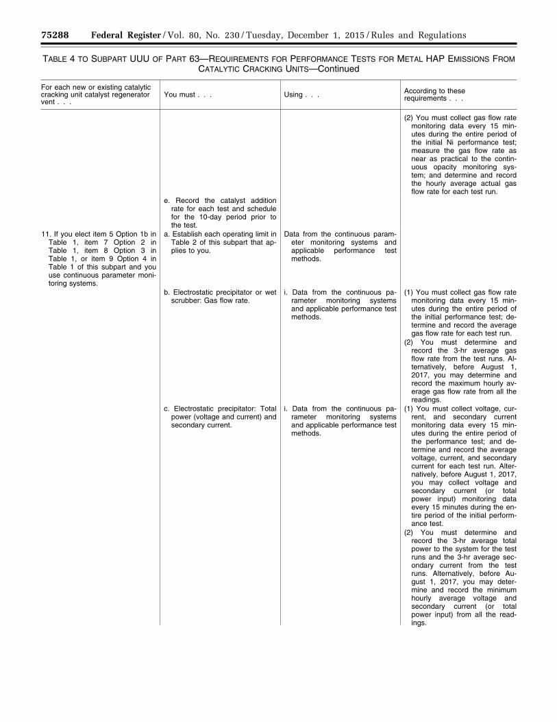
75288 Federal Register / Vol. 80, No. 230 / Tuesday, December 1, 2015 / Rules and Regulations
TABLE 4 TO SUBPART UUU OF PART 63—REQUIREMENTS FOR PERFORMANCE TESTS FOR METAL HAP EMISSIONS FROM CATALYTIC CRACKING UNITS—Continued
For each new or existing catalytic cracking unit catalyst regenerator vent . . .
You must . . . Using . . . According to these requirements . . .
(2) You must collect gas flow rate monitoring data every 15 min-utes during the entire period of the initial Ni performance test; measure the gas flow rate as near as practical to the contin-uous opacity monitoring sys-tem; and determine and record the hourly average actual gas flow rate for each test run.
e. Record the catalyst addition rate for each test and schedule for the 10-day period prior to the test.
11. If you elect item 5 Option 1b in Table 1, item 7 Option 2 in Table 1, item 8 Option 3 in Table 1, or item 9 Option 4 in Table 1 of this subpart and you use continuous parameter moni-toring systems.
a. Establish each operating limit in Table 2 of this subpart that ap-plies to you.
Data from the continuous param-eter monitoring systems and applicable performance test methods.
b. Electrostatic precipitator or wet scrubber: Gas flow rate.
i. Data from the continuous pa-rameter monitoring systems and applicable performance test methods.
(1) You must collect gas flow rate monitoring data every 15 min-utes during the entire period of the initial performance test; de-termine and record the average gas flow rate for each test run.
(2) You must determine and record the 3-hr average gas flow rate from the test runs. Al-ternatively, before August 1, 2017, you may determine and record the maximum hourly av-erage gas flow rate from all the readings.
c. Electrostatic precipitator: Total power (voltage and current) and secondary current.
i. Data from the continuous pa-rameter monitoring systems and applicable performance test methods.
(1) You must collect voltage, cur-rent, and secondary current monitoring data every 15 min-utes during the entire period of the performance test; and de-termine and record the average voltage, current, and secondary current for each test run. Alter-natively, before August 1, 2017, you may collect voltage and secondary current (or total power input) monitoring data every 15 minutes during the en-tire period of the initial perform-ance test.
(2) You must determine and record the 3-hr average total power to the system for the test runs and the 3-hr average sec-ondary current from the test runs. Alternatively, before Au-gust 1, 2017, you may deter-mine and record the minimum hourly average voltage and secondary current (or total power input) from all the read-ings.
VerDate Sep<11>2014 23:11 Nov 30, 2015 Jkt 238001 PO 00000 Frm 00112 Fmt 4701 Sfmt 4700 E:\FR\FM\01DER2.SGM 01DER2tkel
ley
on D
SK
3SP
TV
N1P
RO
D w
ith R
ULE
S2
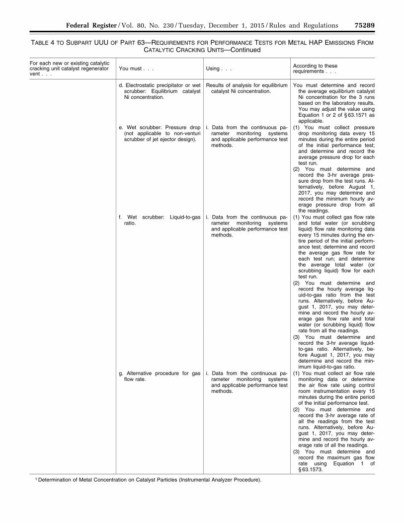
75289 Federal Register / Vol. 80, No. 230 / Tuesday, December 1, 2015 / Rules and Regulations
TABLE 4 TO SUBPART UUU OF PART 63—REQUIREMENTS FOR PERFORMANCE TESTS FOR METAL HAP EMISSIONS FROM CATALYTIC CRACKING UNITS—Continued
For each new or existing catalytic cracking unit catalyst regenerator vent . . .
You must . . . Using . . . According to these requirements . . .
d. Electrostatic precipitator or wet scrubber: Equilibrium catalyst Ni concentration.
Results of analysis for equilibrium catalyst Ni concentration.
You must determine and record the average equilibrium catalyst Ni concentration for the 3 runs based on the laboratory results. You may adjust the value using Equation 1 or 2 of § 63.1571 as applicable.
e. Wet scrubber: Pressure drop (not applicable to non-venturi scrubber of jet ejector design).
i. Data from the continuous pa-rameter monitoring systems and applicable performance test methods.
(1) You must collect pressure drop monitoring data every 15 minutes during the entire period of the initial performance test; and determine and record the average pressure drop for each test run.
(2) You must determine and record the 3-hr average pres-sure drop from the test runs. Al-ternatively, before August 1, 2017, you may determine and record the minimum hourly av-erage pressure drop from all the readings.
f. Wet scrubber: Liquid-to-gas ratio.
i. Data from the continuous pa-rameter monitoring systems and applicable performance test methods.
(1) You must collect gas flow rate and total water (or scrubbing liquid) flow rate monitoring data every 15 minutes during the en-tire period of the initial perform-ance test; determine and record the average gas flow rate for each test run; and determine the average total water (or scrubbing liquid) flow for each test run.
(2) You must determine and record the hourly average liq-uid-to-gas ratio from the test runs. Alternatively, before Au-gust 1, 2017, you may deter-mine and record the hourly av-erage gas flow rate and total water (or scrubbing liquid) flow rate from all the readings.
(3) You must determine and record the 3-hr average liquid- to-gas ratio. Alternatively, be-fore August 1, 2017, you may determine and record the min-imum liquid-to-gas ratio.
g. Alternative procedure for gas flow rate.
i. Data from the continuous pa-rameter monitoring systems and applicable performance test methods.
(1) You must collect air flow rate monitoring data or determine the air flow rate using control room instrumentation every 15 minutes during the entire period of the initial performance test.
(2) You must determine and record the 3-hr average rate of all the readings from the test runs. Alternatively, before Au-gust 1, 2017, you may deter-mine and record the hourly av-erage rate of all the readings.
(3) You must determine and record the maximum gas flow rate using Equation 1 of § 63.1573.
1 Determination of Metal Concentration on Catalyst Particles (Instrumental Analyzer Procedure).
VerDate Sep<11>2014 23:11 Nov 30, 2015 Jkt 238001 PO 00000 Frm 00113 Fmt 4701 Sfmt 4700 E:\FR\FM\01DER2.SGM 01DER2tkel
ley
on D
SK
3SP
TV
N1P
RO
D w
ith R
ULE
S2

75290 Federal Register / Vol. 80, No. 230 / Tuesday, December 1, 2015 / Rules and Regulations
2 EPA Method 6010B, Inductively Coupled Plasma-Atomic Emission Spectrometry, EPA Method 6020, Inductively Coupled Plasma-Mass Spec-trometry, EPA Method 7520, Nickel Atomic Absorption, Direct Aspiration, and EPA Method 7521, Nickel Atomic Absorption, Direct Aspiration are included in ‘‘Test Methods for Evaluating Solid Waste, Physical/Chemical Methods,’’ EPA Publication SW–846, Revision 5 (April 1998). The SW– 846 and Updates (document number 955–001–00000–1) are available for purchase from the Superintendent of Documents, U.S. Government Publishing Office, Washington, DC 20402, (202) 512–1800; and from the National Technical Information Services (NTIS), 5285 Port Royal Road, Springfield, VA 22161, (703) 487–4650. Copies may be inspected at the EPA Docket Center, William Jefferson Clinton (WJC) West Building, (Air Docket), Room 3334, 1301 Constitution Ave. NW., Washington, DC; or at the Office of the Federal Register, 800 North Capitol Street NW., Suite 700, Washington, DC.
■ 56. Table 5 to subpart UUU of part 63 is revised to read as follows:
As stated in § 63.1564(b)(5), you shall meet each requirement in the following table that applies to you.
TABLE 5 TO SUBPART UUU OF PART 63—INITIAL COMPLIANCE WITH METAL HAP EMISSION LIMITS FOR CATALYTIC CRACKING UNITS
For each new and existing catalytic cracking unit catalyst regenerator vent . . .
For the following emission limit . . . You have demonstrated initial compliance if . . .
1. Subject to the NSPS for PM in 40 CFR 60.102 and not electing § 60.100(e).
PM emissions must not exceed 1.0 g/kg (1.0 lb/1,000 lb) of coke burn-off, and the opacity of emissions must not exceed 30 percent, except for one 6-minute average opacity reading in any 1-hour period. Before August 1, 2017, if the discharged gases pass through an incinerator or waste heat boiler in which you burn auxiliary or supplemental liquid or solid fossil fuel, the in-cremental rate of PM must not exceed 43.0 g/GJ or 0.10 lb/mil-lion Btu of heat input attributable to the liquid or solid fossil fuel; and the opacity of emissions must not exceed 30 percent, ex-cept for one 6-minute average opacity reading in any 1-hour period.
You have already conducted a performance test to demonstrate initial compliance with the NSPS and the measured PM emission rate is less than or equal to 1.0 g/kg (1.0 lb/1,000 lb) of coke burn-off in the catalyst regenerator. As part of the Notification of Compliance Status, you must certify that your vent meets the PM limit. You are not required to do another performance test to demonstrate initial compliance. You have already conducted a performance test to demonstrate initial compliance with the NSPS and the average hourly opacity is no more than 30 percent, except that one 6- minute average in any 1-hour period can exceed 30 percent. As part of the Notification of Compliance Status, you must certify that your vent meets the 30 percent opacity limit. As part of your Notifi-cation of Compliance Status, you certify that your continuous opac-ity monitoring system meets the requirements in § 63.1572.
2. Subject to NSPS for PM in 40 CFR 60.102a(b)(1)(i); or in § 60.102 and electing § 60.100(e); electing to meet the PM per coke burn-off limit.
PM emissions must not exceed 1.0 g/kg (1.0 lb PM/1,000 lb) of coke burn-off.
You have already conducted a performance test to demonstrate initial compliance with the NSPS and the measured PM emission rate is less than or equal to 1.0 g/kg (1.0 lb/1,000 lb) of coke burn-off in the catalyst regenerator. As part of the Notification of Compliance Status, you must certify that your vent meets the PM limit. You are not required to do another performance test to demonstrate initial compliance. As part of your Notification of Compliance Status, you certify that your BLD; CO2, O2, or CO monitor; or continuous opac-ity monitoring system meets the requirements in § 63.1572.
3. Subject to NSPS for PM in 40 CFR 60.102a(b)(1)(i), electing to meet the PM per coke burn-off limit.
PM emissions must not exceed 0.5 g/kg (0.5 lb PM/1,000 lb) of coke burn-off).
You have already conducted a performance test to demonstrate initial compliance with the NSPS and the measured PM emission rate is less than or equal to 1.0 g/kg (1.0 lb/1,000 lb) of coke burn-off in the catalyst regenerator. As part of the Notification of Compliance Status, you must certify that your vent meets the PM limit. You are not required to do another performance test to demonstrate initial compliance. As part of your Notification of Compliance Status, you certify that your BLD; CO2, O2, or CO monitor; or continuous opac-ity monitoring system meets the requirements in § 63.1572.
4. Subject to NSPS for PM in 40 CFR 60.102a(b)(1)(i), electing to meet the PM concentration limit.
If a PM CEMS is used, 0.040 grain per dry standard cubic feet (gr/dscf) corrected to 0 percent excess air.
You have already conducted a performance test to demonstrate initial compliance with the NSPS and the measured PM concentration is less than or equal to 0.040 grain per dry standard cubic feet (gr/dscf) corrected to 0 percent excess air. As part of the Notification of Compliance Status, you must certify that your vent meets the PM limit. You are not required to do another performance test to demonstrate initial compliance. As part of your Notification of Com-pliance Status, you certify that your PM CEMS meets the require-ments in § 63.1572.
VerDate Sep<11>2014 23:11 Nov 30, 2015 Jkt 238001 PO 00000 Frm 00114 Fmt 4701 Sfmt 4700 E:\FR\FM\01DER2.SGM 01DER2tkel
ley
on D
SK
3SP
TV
N1P
RO
D w
ith R
ULE
S2

75291 Federal Register / Vol. 80, No. 230 / Tuesday, December 1, 2015 / Rules and Regulations
TABLE 5 TO SUBPART UUU OF PART 63—INITIAL COMPLIANCE WITH METAL HAP EMISSION LIMITS FOR CATALYTIC CRACKING UNITS—Continued
For each new and existing catalytic cracking unit catalyst regenerator vent . . .
For the following emission limit . . . You have demonstrated initial compliance if . . .
5. Subject to NSPS for PM in 40 CFR 60.102a(b)(1)(ii), electing to meet the PM concentration limit.
If a PM CEMS is used, 0.020 gr/dscf corrected to 0 percent ex-cess air.
You have already conducted a performance test to demonstrate initial compliance with the NSPS and the measured PM concentration is less than or equal to 0.020 gr/dscf corrected to 0 percent excess air. As part of the Notification of Compliance Status, you must cer-tify that your vent meets the PM limit. You are not required to do another performance test to demonstrate initial compliance. As part of your Notification of Compliance Status, you certify that your PM CEMS meets the requirements in § 63.1572.
6. Option 1a: Elect NSPS subpart J requirements for PM per coke burn-off limit, not subject to the NSPS for PM in 40 CFR 60.102 or 60.102a(b)(1).
PM emissions must not exceed 1.0 gram per kilogram (g/kg) (1.0 lb/1,000 lb) of coke burn- off, and the opacity of emissions must not exceed 30 percent, ex-cept for one 6-minute average opacity reading in any 1-hour period. Before August 1, 2017, PM emission must not exceed 1.0 g/kg (1.0 lb/1,000 lb) of coke burn-off in the catalyst regen-erator; if the discharged gases pass through an incinerator or waste heat boiler in which you burn auxiliary or supplemental liquid or solid fossil fuel, the in-cremental rate of PM must not exceed 43.0 g/GJ (0.10 lb/mil-lion Btu) of heat input attrib-utable to the liquid or solid fossil fuel; and the opacity of emis-sions must not exceed 30 per-cent, except for one 6-minute average opacity reading in any 1-hour period.
The average PM emission rate, measured using EPA Method 5, 5B, or 5F (for a unit without a wet scrubber) or 5 or 5B (for a unit with a wet scrubber) (40 CFR part 60, appendix A–3), over the period of the initial performance test, is no higher than 1.0 g/kg coke burn- off (1.0 lb/1,000 lb) in the catalyst regenerator. The PM emission rate is calculated using Equations 1, 2, and 3 of § 63.1564. As part of the Notification of Compliance Status, you must certify that your vent meets the PM limit. The average hourly opacity is no more than 30 percent, except that one 6-minute average in any 1-hour period can exceed 30 percent. As part of the Notification of Com-pliance Status, you must certify that your vent meets the 30 per-cent opacity limit. If you use a continuous opacity monitoring sys-tem, your performance evaluation shows the system meets the ap-plicable requirements in § 63.1572.
7. Option 1b: Elect NSPS subpart Ja requirements for PM per coke burn-off limit, not subject to the NSPS for PM in 40 CFR 60.102 or 60.102a(b)(1).
PM emissions must not exceed 1.0 g/kg (1.0 lb/1,000 lb) of coke burn-off.
The average PM emission rate, measured using EPA Method 5, 5B, or 5F (for a unit without a wet scrubber) or 5 or 5B (for a unit with a wet scrubber) (40 CFR part 60, appendix A–3), over the period of the initial performance test, is no higher than 1.0 g/kg coke burn- off (1.0 lb/1,000 lb) in the catalyst regenerator. The PM emission rate is calculated using Equations 1, 2, and 3 of § 63.1564. If you use a BLD; CO2, O2, CO monitor; or continuous opacity monitoring system, your performance evaluation shows the system meets the applicable requirements in § 63.1572.
8. Option 1c: Elect NSPS subpart Ja requirements for PM con-centration limit, not subject to the NSPS for PM in 40 CFR 60.102 or 60.102a(b)(1).
PM emissions must not exceed 0.040 gr/dscf corrected to 0 per-cent excess air.
The average PM concentration, measured using EPA Method 5, 5B, or 5F (for a unit without a wet scrubber) or Method 5 or 5B (for a unit with a wet scrubber) (40 CFR part 60, appendix A–3), over the period of the initial performance test, is less than or equal to 0.040 gr/dscf corrected to 0 percent excess air. Your performance eval-uation shows your PM CEMS meets the applicable requirements in § 63.1572.
9. Option 2: PM per coke burn-off limit, not subject to the NSPS for PM in 40 CFR 60.102 or 60.102a(b)(1).
PM emissions must not exceed 1.0 g/kg (1.0 lb/1,000 lb) of coke burn-off.
The average PM emission rate, measured using EPA Method 5, 5B, or 5F (for a unit without a wet scrubber) or 5 or 5B (for a unit with a wet scrubber) (40 CFR part 60, appendix A–3), over the period of the initial performance test, is no higher than 1.0 g/kg coke burn- off (1.0 lb/1,000 lb) in the catalyst regenerator. The PM emission rate is calculated using Equations 1, 2, and 3 of § 63.1564. If you use a BLD; CO2, O2, CO monitor; or continuous opacity monitoring system, your performance evaluation shows the system meets the applicable requirements in § 63.1572.
10. Option 3: Ni lb/hr limit, not sub-ject to the NSPS for PM in 40 CFR 60.102 or 60.102a(b)(1).
Nickel (Ni) emissions from your catalyst regenerator vent must not exceed 13,000 mg/hr (0.029 lb/hr).
The average Ni emission rate, measured using Method 29 (40 CFR part 60, appendix A–8) over the period of the initial performance test, is not more than 13,000 mg/hr (0.029 lb/hr). The Ni emission rate is calculated using Equation 5 of § 63.1564; and if you use a BLD; CO2, O2, or CO monitor; or continuous opacity monitoring system, your performance evaluation shows the system meets the applicable requirements in § 63.1572.
VerDate Sep<11>2014 23:11 Nov 30, 2015 Jkt 238001 PO 00000 Frm 00115 Fmt 4701 Sfmt 4700 E:\FR\FM\01DER2.SGM 01DER2tkel
ley
on D
SK
3SP
TV
N1P
RO
D w
ith R
ULE
S2
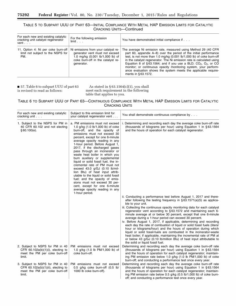
75292 Federal Register / Vol. 80, No. 230 / Tuesday, December 1, 2015 / Rules and Regulations
TABLE 5 TO SUBPART UUU OF PART 63—INITIAL COMPLIANCE WITH METAL HAP EMISSION LIMITS FOR CATALYTIC CRACKING UNITS—Continued
For each new and existing catalytic cracking unit catalyst regenerator vent . . .
For the following emission limit . . . You have demonstrated initial compliance if . . .
11. Option 4: Ni per coke burn-off limit not subject to the NSPS for PM.
Ni emissions from your catalyst re-generator vent must not exceed 1.0 mg/kg (0.001 lb/1,000 lb) of coke burn-off in the catalyst re-generator.
The average Ni emission rate, measured using Method 29 (40 CFR part 60, appendix A–8) over the period of the initial performance test, is not more than 1.0 mg/kg (0.001 lb/1,000 lb) of coke burn-off in the catalyst regenerator. The Ni emission rate is calculated using Equation 8 of § 63.1564; and if you use a BLD; CO2, O2, or CO monitor; or continuous opacity monitoring system, your perform-ance evaluation shows the system meets the applicable require-ments in § 63.1572.
■ 57. Table 6 to subpart UUU of part 63 is revised to read as follows:
As stated in § 63.1564(c)(1), you shall meet each requirement in the following table that applies to you.
TABLE 6 TO SUBPART UUU OF PART 63—CONTINUOUS COMPLIANCE WITH METAL HAP EMISSION LIMITS FOR CATALYTIC CRACKING UNITS
For each new and existing catalytic cracking unit . . .
Subject to this emission limit for your catalyst regenerator vent . . . You shall demonstrate continuous compliance by . . .
1. Subject to the NSPS for PM in 40 CFR 60.102 and not electing § 60.100(e).
a. PM emissions must not exceed 1.0 g/kg (1.0 lb/1,000 lb) of coke burn-off, and the opacity of emissions must not exceed 30 percent, except for one 6-minute average opacity reading in any 1-hour period. Before August 1, 2017, if the discharged gases pass through an incinerator or waste heat boiler in which you burn auxiliary or supplemental liquid or solid fossil fuel, the in-cremental rate of PM must not exceed 43.0 g/GJ (0.10 lb/mil-lion Btu) of heat input attrib-utable to the liquid or solid fossil fuel; and the opacity of emis-sions must not exceed 30 per-cent, except for one 6-minute average opacity reading in any 1-hour period.
i. Determining and recording each day the average coke burn-off rate (thousands of kilograms per hour) using Equation 1 in § 63.1564 and the hours of operation for each catalyst regenerator.
ii. Conducting a performance test before August 1, 2017 and there-after following the testing frequency in § 63.1571(a)(5) as applica-ble to your unit.
iii. Collecting the continuous opacity monitoring data for each catalyst regenerator vent according to § 63.1572 and maintaining each 6- minute average at or below 30 percent, except that one 6-minute average during a 1-hour period can exceed 30 percent.
iv. Before August 1, 2017, if applicable, determining and recording each day the rate of combustion of liquid or solid fossil fuels (liters/hour or kilograms/hour) and the hours of operation during which liquid or solid fossil-fuels are combusted in the incinerator-waste heat boiler; if applicable, maintaining the incremental rate of PM at or below 43 g/GJ (0.10 lb/million Btu) of heat input attributable to the solid or liquid fossil fuel.
2. Subject to NSPS for PM in 40 CFR 60.102a(b)(1)(i), electing to meet the PM per coke burn-off limit.
PM emissions must not exceed 1.0 g/kg (1.0 lb PM/1,000 lb) of coke burn-off.
Determining and recording each day the average coke burn-off rate (thousands of kilograms per hour) using Equation 1 in § 63.1564 and the hours of operation for each catalyst regenerator; maintain-ing PM emission rate below 1.0 g/kg (1.0 lb PM/1,000 lb) of coke burn-off; and conducting a performance test once every year.
3. Subject to NSPS for PM in 40 CFR 60.102a(b)(1)(ii), electing to meet the PM per coke burn-off limit.
PM emissions must not exceed 0.5 g/kg coke burn-off (0.5 lb/1000 lb coke burn-off).
Determining and recording each day the average coke burn-off rate (thousands of kilograms per hour) using Equation 1 in § 63.1564 and the hours of operation for each catalyst regenerator; maintain-ing PM emission rate below 0.5 g/kg (0.5 lb/1,000 lb) of coke burn- off; and conducting a performance test once every year.
VerDate Sep<11>2014 23:11 Nov 30, 2015 Jkt 238001 PO 00000 Frm 00116 Fmt 4701 Sfmt 4700 E:\FR\FM\01DER2.SGM 01DER2tkel
ley
on D
SK
3SP
TV
N1P
RO
D w
ith R
ULE
S2
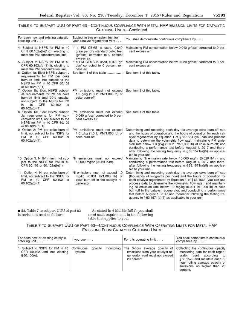
75293 Federal Register / Vol. 80, No. 230 / Tuesday, December 1, 2015 / Rules and Regulations
TABLE 6 TO SUBPART UUU OF PART 63—CONTINUOUS COMPLIANCE WITH METAL HAP EMISSION LIMITS FOR CATALYTIC CRACKING UNITS—Continued
For each new and existing catalytic cracking unit . . .
Subject to this emission limit for your catalyst regenerator vent . . . You shall demonstrate continuous compliance by . . .
4. Subject to NSPS for PM in 40 CFR 60.102a(b)(1)(i), electing to meet the PM concentration limit.
If a PM CEMS is used, 0.040 grain per dry standard cubic feet (gr/dscf) corrected to 0 percent excess air.
Maintaining PM concentration below 0.040 gr/dscf corrected to 0 per-cent excess air.
5. Subject to NSPS for PM in 40 CFR 60.102a(b)(1)(ii), electing to meet the PM concentration limit.
If a PM CEMS is used, 0.020 gr/dscf corrected to 0 percent ex-cess air.
Maintaining PM concentration below 0.020 gr/dscf corrected to 0 per-cent excess air.
6. Option 1a: Elect NSPS subpart J requirements for PM per coke burn-off limit, not subject to the NSPS for PM in 40 CFR 60.102 or 60.102a(b)(1).
See item 1 of this table ................. See item 1 of this table.
7. Option 1b: Elect NSPS subpart Ja requirements for PM per coke burn-off limit and 30% opacity, not subject to the NSPS for PM in 40 CFR 60.102 or 60.102a(b)(1).
PM emissions must not exceed 1.0 g/kg (1.0 lb PM/1,000 lb) of coke burn-off.
See item 2 of this table.
8. Option 1c: Elect NSPS subpart Ja requirements for PM con-centration limit, not subject to the NSPS for PM in 40 CFR 60.102 or 60.102a(b)(1).
PM emissions must not exceed 0.040 gr/dscf corrected to 0 per-cent excess air.
See item 4 of this table.
9. Option 2: PM per coke burn-off limit, not subject to the NSPS for PM in 40 CFR 60.102 or 60.102a(b)(1).
PM emissions must not exceed 1.0 g/kg (1.0 lb PM/1,000 lb) of coke burn-off.
Determining and recording each day the average coke burn-off rate and the hours of operation and the hours of operation for each cat-alyst regenerator by Equation 1 of § 63.1564 (you can use process data to determine the volumetric flow rate); maintaining PM emis-sion rate below 1.0 g/kg (1.0 lb PM/1,000 lb) of coke burn-off; and conducting a performance test before August 1, 2017 and there-after following the testing frequency in § 63.1571(a)(5) as applica-ble to your unit.
10. Option 3: Ni lb/hr limit, not sub-ject to the NSPS for PM in 40 CFR 60.102 or 60.102a(b)(1).
Ni emissions must not exceed 13,000 mg/hr (0.029 lb/hr).
Maintaining Ni emission rate below 13,000 mg/hr (0.029 lb/hr); and conducting a performance test before August 1, 2017 and there-after following the testing frequency in § 63.1571(a)(5) as applica-ble to your unit.
11. Option 4: Ni per coke burn-off limit, not subject to the NSPS for PM in 40 CFR 60.102 or 60.102a(b)(1).
Ni emissions must not exceed 1.0 mg/kg (0.001 lb/1,000 lb) of coke burn-off in the catalyst re-generator.
Determining and recording each day the average coke burn-off rate (thousands of kilograms per hour) and the hours of operation for each catalyst regenerator by Equation 1 of § 63.1564 (you can use process data to determine the volumetric flow rate); and maintain-ing Ni emission rate below 1.0 mg/kg (0.001 lb/1,000 lb) of coke burn-off in the catalyst regenerator; and conducting a performance test before August 1, 2017 and thereafter following the testing fre-quency in § 63.1571(a)(5) as applicable to your unit.
■ 58. Table 7 to subpart UUU of part 63 is revised to read as follows:
As stated in § 63.1564(c)(1), you shall meet each requirement in the following table that applies to you.
TABLE 7 TO SUBPART UUU OF PART 63—CONTINUOUS COMPLIANCE WITH OPERATING LIMITS FOR METAL HAP EMISSIONS FROM CATALYTIC CRACKING UNITS
For each new or existing catalytic cracking unit . . . If you use . . . For this operating limit . . . You shall demonstrate continuous
compliance by . . .
1. Subject to NSPS for PM in 40 CFR 60.102 and not electing § 60.100(e).
Continuous opacity monitoring system.
The 3-hour average opacity of emissions from your catalyst re-generator vent must not exceed 20 percent.
Collecting the continuous opacity monitoring data for each regen-erator vent according to § 63.1572 and maintain each 3- hour rolling average opacity of emissions no higher than 20 percent.
VerDate Sep<11>2014 23:11 Nov 30, 2015 Jkt 238001 PO 00000 Frm 00117 Fmt 4701 Sfmt 4700 E:\FR\FM\01DER2.SGM 01DER2tkel
ley
on D
SK
3SP
TV
N1P
RO
D w
ith R
ULE
S2
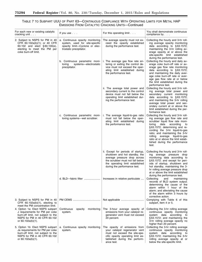
75294 Federal Register / Vol. 80, No. 230 / Tuesday, December 1, 2015 / Rules and Regulations
TABLE 7 TO SUBPART UUU OF PART 63—CONTINUOUS COMPLIANCE WITH OPERATING LIMITS FOR METAL HAP EMISSIONS FROM CATALYTIC CRACKING UNITS—Continued
For each new or existing catalytic cracking unit . . . If you use . . . For this operating limit . . . You shall demonstrate continuous
compliance by . . .
2. Subject to NSPS for PM in 40 CFR 60.102a(b)(1); or 40 CFR 60.102 and elect § 60.100(e), electing to meet the PM per coke burn-off limit.
a. Continuous opacity monitoring system, used for site-specific opacity limit—Cyclone or elec-trostatic precipitator.
The average opacity must not ex-ceed the opacity established during the performance test.
Collecting the hourly and 3-hr roll-ing average opacity monitoring data according to § 63.1572; maintaining the 3-hr rolling av-erage opacity at or above the site-specific limit established during the performance test.
b. Continuous parametric moni-toring systems—electrostatic precipitator.
i. The average gas flow rate en-tering or exiting the control de-vice must not exceed the oper-ating limit established during the performance test.
Collecting the hourly and daily av-erage coke burn-off rate or av-erage gas flow rate monitoring data according to § 63.1572; and maintaining the daily aver-age coke burn-off rate or aver-age gas flow rate at or below the limit established during the performance test.
ii. The average total power and secondary current to the control device must not fall below the operating limit established dur-ing the performance test.
Collecting the hourly and 3-hr roll-ing average total power and secondary current monitoring data according to § 63.1572; and maintaining the 3-hr rolling average total power and sec-ondary current at or above the limit established during the per-formance test.
c. Continuous parametric moni-toring systems—wet scrubber.
i. The average liquid-to-gas ratio must not fall below the oper-ating limit established during the performance test.
Collecting the hourly and 3-hr roll-ing average gas flow rate and scrubber liquid flow rate moni-toring data according to § 63.1572; determining and re-cording the 3-hr liquid-to-gas ratio; and maintaining the 3-hr rolling average liquid-to-gas ratio at or above the limit estab-lished during the performance test.
ii. Except for periods of startup, shutdown and hot standby, the average pressure drop across the scrubber must not fall below the operating limit established during the performance test.
Collecting the hourly and 3-hr roll-ing average pressure drop monitoring data according to § 63.1572; and except for peri-ods of startup, shutdown and hot standby, maintaining the 3- hr rolling average pressure drop at or above the limit established during the performance test.
d. BLD—fabric filter ...................... Increases in relative particulate .... Collecting and maintaining records of BLD system output; determining the cause of the alarm within 1 hour of the alarm; and alleviating the cause of the alarm within 3 hours by corrective action.
3. Subject to NSPS for PM in 40 CFR 60.102a(b)(1), electing to meet the PM concentration limit.
PM CEMS ..................................... Not applicable ............................... Complying with Table 6 of this subpart, item 4 or 5.
4. Option 1a: Elect NSPS subpart J requirements for PM per coke burn-off limit, not subject to the NSPS for PM in 40 CFR 60.102 or 60.102a(b)(1).
Continuous opacity monitoring system.
The 3-hour average opacity of emissions from your catalyst re-generator vent must not exceed 20 percent.
Collecting the 3-hr rolling average continuous opacity monitoring system data according to § 63.1572; and maintaining the 3-hr rolling average opacity no higher than 20 percent.
5. Option 1b: Elect NSPS subpart Ja requirements for PM per coke burn-off limit, not subject to the NSPS for PM in 40 CFR 60.102 or 60.102a(b)(1).
a. Continuous opacity monitoring system.
The opacity of emissions from your catalyst regenerator vent must not exceed the site-spe-cific opacity operating limit es-tablished during the perform-ance test.
Collecting the 3-hr rolling average continuous opacity monitoring system data according to § 63.1572; maintaining the 3-hr rolling average opacity at or below the site-specific limit.
VerDate Sep<11>2014 23:11 Nov 30, 2015 Jkt 238001 PO 00000 Frm 00118 Fmt 4701 Sfmt 4700 E:\FR\FM\01DER2.SGM 01DER2tkel
ley
on D
SK
3SP
TV
N1P
RO
D w
ith R
ULE
S2

75295 Federal Register / Vol. 80, No. 230 / Tuesday, December 1, 2015 / Rules and Regulations
TABLE 7 TO SUBPART UUU OF PART 63—CONTINUOUS COMPLIANCE WITH OPERATING LIMITS FOR METAL HAP EMISSIONS FROM CATALYTIC CRACKING UNITS—Continued
For each new or existing catalytic cracking unit . . . If you use . . . For this operating limit . . . You shall demonstrate continuous
compliance by . . .
b. Continuous parametric moni-toring systems—electrostatic precipitator.
See item 2.b of this table ............. See item 2.b of this table.
c. Continuous parametric moni-toring systems—wet scrubber.
See item 2.c of this table ............. See item 2.c of this table.
d. BLD—fabric filter ...................... See item 2.d of this table ............. See item 2.d of this table. 6. Option 1c: Elect NSPS subpart
Ja requirements for PM con-centration limit, not subject to the NSPS for PM in 40 CFR 60.102 or 60.102a(b)(1).
PM CEMS ..................................... Not applicable ............................... Complying with Table 6 of this subpart, item 4.
7. Option 2: PM per coke burn-off limit, not subject to the NSPS for PM in 40 CFR 60.102 or 60.102a(b)(1).
a. Continuous opacity monitoring system.
The opacity of emissions from your catalyst regenerator vent must not exceed the site-spe-cific opacity operating limit es-tablished during the perform-ance test.
Collecting the hourly and 3-hr roll-ing average continuous opacity monitoring system data accord-ing to § 63.1572; and maintain-ing the 3-hr rolling average opacity at or below the site-spe-cific limit established during the performance test. Alternatively, before August 1, 2017, col-lecting the hourly average con-tinuous opacity monitoring sys-tem data according to § 63.1572; and maintaining the hourly average opacity at or below the site-specific limit.
b. Continuous parameter moni-toring systems—electrostatic precipitator.
i. The average coke burn-off rate or average gas flow rate enter-ing or exiting the control device must not exceed the operating limit established during the per-formance test.
Collecting the hourly and daily av-erage coke burn-off rate or gas flow rate monitoring data ac-cording to § 63.1572; and main-taining the daily coke burn-off rate or average gas flow rate at or below the limit established during the performance test.
ii. The average total power (volt-age and current) and secondary current to the control device must not fall below the oper-ating limit established during the performance test.
Collecting the hourly and 3-hr roll-ing average total power and secondary current monitoring data according to § 63.1572; and maintaining the 3-hr rolling average total power and sec-ondary current at or above the limit established during the per-formance test. Alternatively, be-fore August 1, 2017, collecting the hourly and daily average voltage and secondary current (or total power input) monitoring data according to § 63.1572; and maintaining the daily aver-age voltage and secondary cur-rent (or total power input) at or above the limit established dur-ing the performance test.
VerDate Sep<11>2014 23:11 Nov 30, 2015 Jkt 238001 PO 00000 Frm 00119 Fmt 4701 Sfmt 4700 E:\FR\FM\01DER2.SGM 01DER2tkel
ley
on D
SK
3SP
TV
N1P
RO
D w
ith R
ULE
S2

75296 Federal Register / Vol. 80, No. 230 / Tuesday, December 1, 2015 / Rules and Regulations
TABLE 7 TO SUBPART UUU OF PART 63—CONTINUOUS COMPLIANCE WITH OPERATING LIMITS FOR METAL HAP EMISSIONS FROM CATALYTIC CRACKING UNITS—Continued
For each new or existing catalytic cracking unit . . . If you use . . . For this operating limit . . . You shall demonstrate continuous
compliance by . . .
c. Continuous parameter moni-toring systems—wet scrubber.
i. The average liquid-to-gas ratio must not fall below the oper-ating limit established during the performance test.
Collecting the hourly and 3-hr roll-ing average gas flow rate and scrubber liquid flow rate moni-toring data according to § 63.1572; determining and re-cording the 3-hr liquid-to-gas ratio; and maintaining the 3-hr rolling average liquid-to-gas ratio at or above the limit estab-lished during the performance test. Alternatively, before Au-gust 1, 2017, collecting the hourly average gas flow rate and water (or scrubbing liquid) flow rate monitoring data ac-cording to § 63.1572 1; deter-mining and recording the hourly average liquid-to-gas ratio; de-termining and recording the daily average liquid-to-gas ratio; and maintaining the daily aver-age liquid-to-gas ratio above the limit established during the performance test.
ii. Except for periods of startup, shutdown and hot standby, the average pressure drop across the scrubber must not fall below the operating limit established during the performance test.
Collecting the hourly and 3-hr roll-ing average pressure drop monitoring data according to § 63.1572; and except for peri-ods of startup, shutdown and hot standby, maintaining the 3- hr rolling average pressure drop at or above the limit established during the performance test. Al-ternatively, before August 1, 2017, collecting the hourly and daily average pressure drop monitoring data according to § 63.1572; and maintaining the daily average pressure drop above the limit established dur-ing the performance test.
d. BLD—fabric filter ...................... See item 2.d of this table ............. See item 2.d of this table. 8. Option 3: Ni lb/hr limit not sub-
ject to the NSPS for PM in 40 CFR 60.102.
a. Continuous opacity monitoring system.
i. The daily average Ni operating value must not exceed the site- specific Ni operating limit estab-lished during the performance test.
(1) Collecting the hourly average continuous opacity monitoring system data according to § 63.1572; determining and re-cording equilibrium catalyst Ni concentration at least once a week 2; collecting the hourly av-erage gas flow rate monitoring data according to § 63.1572 1; and determining and recording the hourly average Ni operating value using Equation 11 of § 63.1564.
VerDate Sep<11>2014 23:11 Nov 30, 2015 Jkt 238001 PO 00000 Frm 00120 Fmt 4701 Sfmt 4700 E:\FR\FM\01DER2.SGM 01DER2tkel
ley
on D
SK
3SP
TV
N1P
RO
D w
ith R
ULE
S2
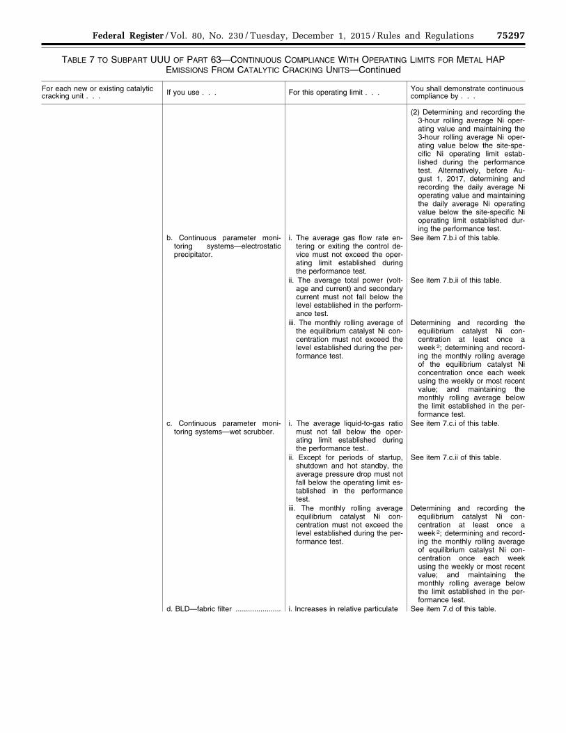
75297 Federal Register / Vol. 80, No. 230 / Tuesday, December 1, 2015 / Rules and Regulations
TABLE 7 TO SUBPART UUU OF PART 63—CONTINUOUS COMPLIANCE WITH OPERATING LIMITS FOR METAL HAP EMISSIONS FROM CATALYTIC CRACKING UNITS—Continued
For each new or existing catalytic cracking unit . . . If you use . . . For this operating limit . . . You shall demonstrate continuous
compliance by . . .
(2) Determining and recording the 3-hour rolling average Ni oper-ating value and maintaining the 3-hour rolling average Ni oper-ating value below the site-spe-cific Ni operating limit estab-lished during the performance test. Alternatively, before Au-gust 1, 2017, determining and recording the daily average Ni operating value and maintaining the daily average Ni operating value below the site-specific Ni operating limit established dur-ing the performance test.
b. Continuous parameter moni-toring systems—electrostatic precipitator.
i. The average gas flow rate en-tering or exiting the control de-vice must not exceed the oper-ating limit established during the performance test.
See item 7.b.i of this table.
ii. The average total power (volt-age and current) and secondary current must not fall below the level established in the perform-ance test.
See item 7.b.ii of this table.
iii. The monthly rolling average of the equilibrium catalyst Ni con-centration must not exceed the level established during the per-formance test.
Determining and recording the equilibrium catalyst Ni con-centration at least once a week 2; determining and record-ing the monthly rolling average of the equilibrium catalyst Ni concentration once each week using the weekly or most recent value; and maintaining the monthly rolling average below the limit established in the per-formance test.
c. Continuous parameter moni-toring systems—wet scrubber.
i. The average liquid-to-gas ratio must not fall below the oper-ating limit established during the performance test..
See item 7.c.i of this table.
ii. Except for periods of startup, shutdown and hot standby, the average pressure drop must not fall below the operating limit es-tablished in the performance test.
See item 7.c.ii of this table.
iii. The monthly rolling average equilibrium catalyst Ni con-centration must not exceed the level established during the per-formance test.
Determining and recording the equilibrium catalyst Ni con-centration at least once a week 2; determining and record-ing the monthly rolling average of equilibrium catalyst Ni con-centration once each week using the weekly or most recent value; and maintaining the monthly rolling average below the limit established in the per-formance test.
d. BLD—fabric filter ...................... i. Increases in relative particulate See item 7.d of this table.
VerDate Sep<11>2014 23:11 Nov 30, 2015 Jkt 238001 PO 00000 Frm 00121 Fmt 4701 Sfmt 4700 E:\FR\FM\01DER2.SGM 01DER2tkel
ley
on D
SK
3SP
TV
N1P
RO
D w
ith R
ULE
S2

75298 Federal Register / Vol. 80, No. 230 / Tuesday, December 1, 2015 / Rules and Regulations
TABLE 7 TO SUBPART UUU OF PART 63—CONTINUOUS COMPLIANCE WITH OPERATING LIMITS FOR METAL HAP EMISSIONS FROM CATALYTIC CRACKING UNITS—Continued
For each new or existing catalytic cracking unit . . . If you use . . . For this operating limit . . . You shall demonstrate continuous
compliance by . . .
ii. The monthly rolling average of the equilibrium catalyst Ni con-centration must not exceed the level established during the per-formance test.
Determining and recording the equilibrium catalyst Ni con-centration at least once a week 2; determining and record-ing the monthly rolling average of the equilibrium catalyst Ni concentration once each week using the weekly or most recent value; and maintaining the monthly rolling average below the limit established in the per-formance test.
9. Option 4: Ni per coke burn-off limit not subject to the NSPS for PM in 40 CFR 60.102.
a. Continuous opacity monitoring system.
i. The daily average Ni operating value must not exceed the site- specific Ni operating limit estab-lished during the performance test.
(1) Collecting the hourly average continuous opacity monitoring system data according to § 63.1572; collecting the hourly average coke burn rate and hourly average gas flow rate monitoring data according to § 63.15721; determining and re-cording equilibrium catalyst Ni concentration at least once a week 2; and determining and re-cording the hourly average Ni operating value using Equation 12 of § 63.1564.
(2) Determining and recording the 3-hour rolling average Ni oper-ating value and maintaining the 3-hour rolling average Ni oper-ating value below the site-spe-cific Ni operating limit estab-lished during the performance test Alternatively, before August 1, 2017, determining and re-cording the daily average Ni op-erating value and maintaining the daily average Ni operating value below the site-specific Ni operating limit established dur-ing the performance test.
b. Continuous parameter moni-toring systems—electrostatic precipitator.
i. The average gas flow rate to the control device must not ex-ceed the level established in the performance test.
See item 7.b.i of this table.
ii. The average voltage and sec-ondary current (or total power input) must not fall below the level established in the perform-ance test.
See item 7.b.ii of this table.
iii. The monthly rolling average equilibrium catalyst Ni con-centration must not exceed the level established during the per-formance test.
See item 8.b.iii of this table.
c. Continuous parameter moni-toring systems—wet scrubber.
i. The average liquid-to-gas ratio must not fall below the oper-ating limit established during the performance test.
See item 7.c.i of this table.
ii. Except for periods of startup, shutdown and hot standby, the daily average pressure drop must not fall below the oper-ating limit established in the performance test.
See item 7.c.ii of this table.
VerDate Sep<11>2014 23:11 Nov 30, 2015 Jkt 238001 PO 00000 Frm 00122 Fmt 4701 Sfmt 4700 E:\FR\FM\01DER2.SGM 01DER2tkel
ley
on D
SK
3SP
TV
N1P
RO
D w
ith R
ULE
S2
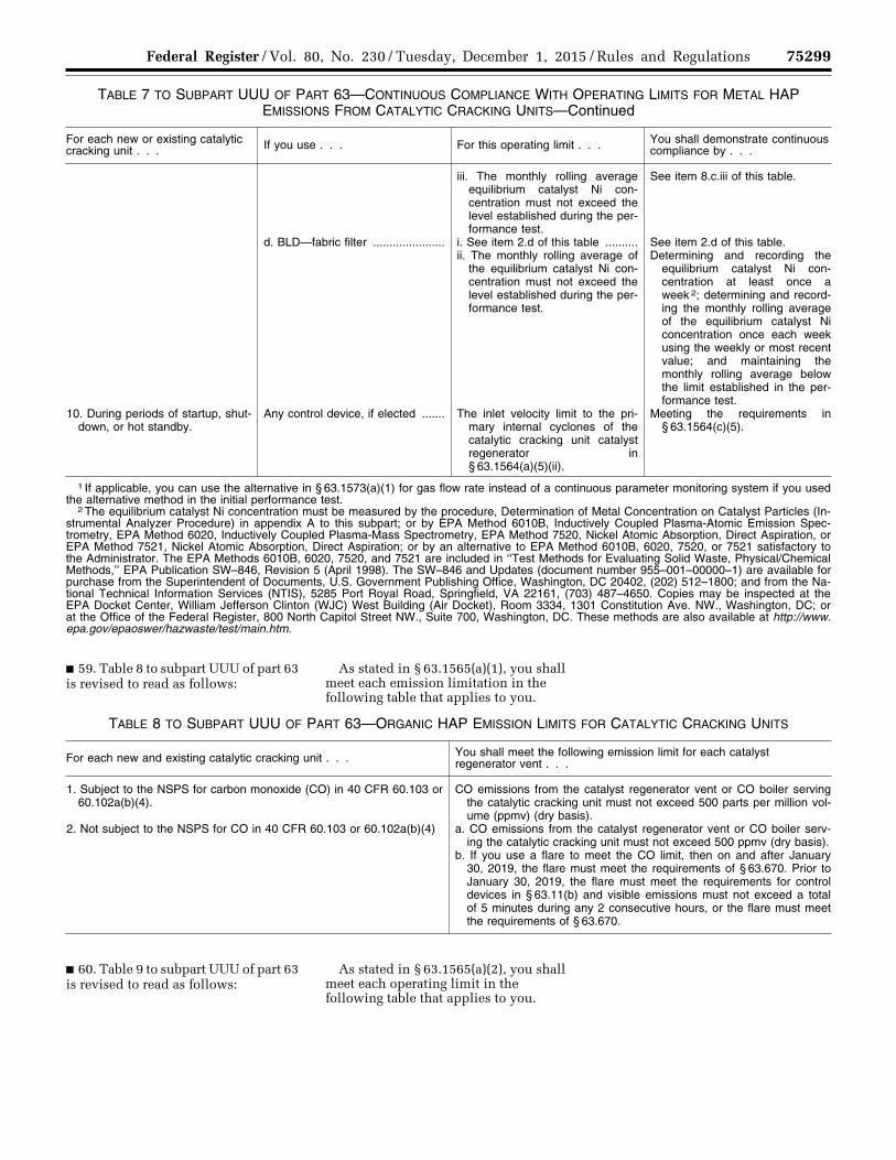
75299 Federal Register / Vol. 80, No. 230 / Tuesday, December 1, 2015 / Rules and Regulations
TABLE 7 TO SUBPART UUU OF PART 63—CONTINUOUS COMPLIANCE WITH OPERATING LIMITS FOR METAL HAP EMISSIONS FROM CATALYTIC CRACKING UNITS—Continued
For each new or existing catalytic cracking unit . . . If you use . . . For this operating limit . . . You shall demonstrate continuous
compliance by . . .
iii. The monthly rolling average equilibrium catalyst Ni con-centration must not exceed the level established during the per-formance test.
See item 8.c.iii of this table.
d. BLD—fabric filter ...................... i. See item 2.d of this table .......... See item 2.d of this table. ii. The monthly rolling average of
the equilibrium catalyst Ni con-centration must not exceed the level established during the per-formance test.
Determining and recording the equilibrium catalyst Ni con-centration at least once a week 2; determining and record-ing the monthly rolling average of the equilibrium catalyst Ni concentration once each week using the weekly or most recent value; and maintaining the monthly rolling average below the limit established in the per-formance test.
10. During periods of startup, shut-down, or hot standby.
Any control device, if elected ....... The inlet velocity limit to the pri-mary internal cyclones of the catalytic cracking unit catalyst regenerator in § 63.1564(a)(5)(ii).
Meeting the requirements in § 63.1564(c)(5).
1 If applicable, you can use the alternative in § 63.1573(a)(1) for gas flow rate instead of a continuous parameter monitoring system if you used the alternative method in the initial performance test.
2 The equilibrium catalyst Ni concentration must be measured by the procedure, Determination of Metal Concentration on Catalyst Particles (In-strumental Analyzer Procedure) in appendix A to this subpart; or by EPA Method 6010B, Inductively Coupled Plasma-Atomic Emission Spec-trometry, EPA Method 6020, Inductively Coupled Plasma-Mass Spectrometry, EPA Method 7520, Nickel Atomic Absorption, Direct Aspiration, or EPA Method 7521, Nickel Atomic Absorption, Direct Aspiration; or by an alternative to EPA Method 6010B, 6020, 7520, or 7521 satisfactory to the Administrator. The EPA Methods 6010B, 6020, 7520, and 7521 are included in ‘‘Test Methods for Evaluating Solid Waste, Physical/Chemical Methods,’’ EPA Publication SW–846, Revision 5 (April 1998). The SW–846 and Updates (document number 955–001–00000–1) are available for purchase from the Superintendent of Documents, U.S. Government Publishing Office, Washington, DC 20402, (202) 512–1800; and from the Na-tional Technical Information Services (NTIS), 5285 Port Royal Road, Springfield, VA 22161, (703) 487–4650. Copies may be inspected at the EPA Docket Center, William Jefferson Clinton (WJC) West Building (Air Docket), Room 3334, 1301 Constitution Ave. NW., Washington, DC; or at the Office of the Federal Register, 800 North Capitol Street NW., Suite 700, Washington, DC. These methods are also available at http://www.epa.gov/epaoswer/hazwaste/test/main.htm.
■ 59. Table 8 to subpart UUU of part 63 is revised to read as follows:
As stated in § 63.1565(a)(1), you shall meet each emission limitation in the following table that applies to you.
TABLE 8 TO SUBPART UUU OF PART 63—ORGANIC HAP EMISSION LIMITS FOR CATALYTIC CRACKING UNITS
For each new and existing catalytic cracking unit . . . You shall meet the following emission limit for each catalyst regenerator vent . . .
1. Subject to the NSPS for carbon monoxide (CO) in 40 CFR 60.103 or 60.102a(b)(4).
CO emissions from the catalyst regenerator vent or CO boiler serving the catalytic cracking unit must not exceed 500 parts per million vol-ume (ppmv) (dry basis).
2. Not subject to the NSPS for CO in 40 CFR 60.103 or 60.102a(b)(4) a. CO emissions from the catalyst regenerator vent or CO boiler serv-ing the catalytic cracking unit must not exceed 500 ppmv (dry basis).
b. If you use a flare to meet the CO limit, then on and after January 30, 2019, the flare must meet the requirements of § 63.670. Prior to January 30, 2019, the flare must meet the requirements for control devices in § 63.11(b) and visible emissions must not exceed a total of 5 minutes during any 2 consecutive hours, or the flare must meet the requirements of § 63.670.
■ 60. Table 9 to subpart UUU of part 63 is revised to read as follows:
As stated in § 63.1565(a)(2), you shall meet each operating limit in the following table that applies to you.
VerDate Sep<11>2014 23:11 Nov 30, 2015 Jkt 238001 PO 00000 Frm 00123 Fmt 4701 Sfmt 4700 E:\FR\FM\01DER2.SGM 01DER2tkel
ley
on D
SK
3SP
TV
N1P
RO
D w
ith R
ULE
S2
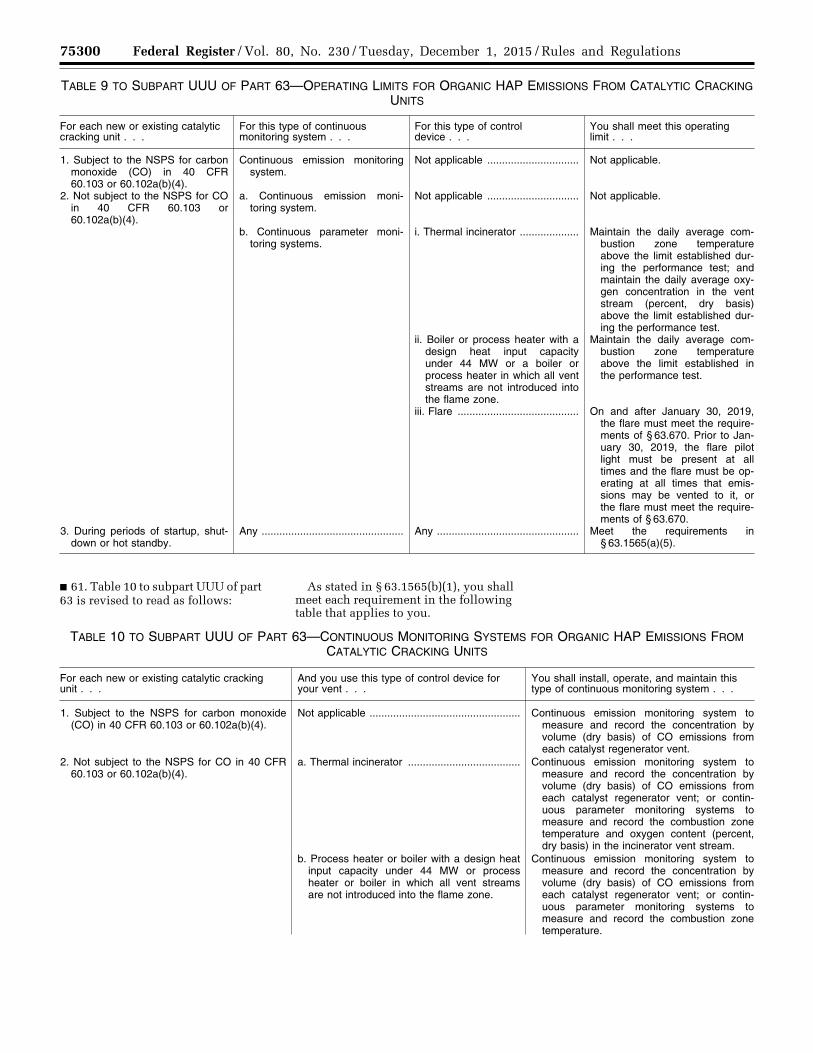
75300 Federal Register / Vol. 80, No. 230 / Tuesday, December 1, 2015 / Rules and Regulations
TABLE 9 TO SUBPART UUU OF PART 63—OPERATING LIMITS FOR ORGANIC HAP EMISSIONS FROM CATALYTIC CRACKING UNITS
For each new or existing catalytic cracking unit . . .
For this type of continuous monitoring system . . .
For this type of control device . . .
You shall meet this operating limit . . .
1. Subject to the NSPS for carbon monoxide (CO) in 40 CFR 60.103 or 60.102a(b)(4).
Continuous emission monitoring system.
Not applicable ............................... Not applicable.
2. Not subject to the NSPS for CO in 40 CFR 60.103 or 60.102a(b)(4).
a. Continuous emission moni-toring system.
Not applicable ............................... Not applicable.
b. Continuous parameter moni-toring systems.
i. Thermal incinerator .................... Maintain the daily average com-bustion zone temperature above the limit established dur-ing the performance test; and maintain the daily average oxy-gen concentration in the vent stream (percent, dry basis) above the limit established dur-ing the performance test.
ii. Boiler or process heater with a design heat input capacity under 44 MW or a boiler or process heater in which all vent streams are not introduced into the flame zone.
Maintain the daily average com-bustion zone temperature above the limit established in the performance test.
iii. Flare ......................................... On and after January 30, 2019, the flare must meet the require-ments of § 63.670. Prior to Jan-uary 30, 2019, the flare pilot light must be present at all times and the flare must be op-erating at all times that emis-sions may be vented to it, or the flare must meet the require-ments of § 63.670.
3. During periods of startup, shut-down or hot standby.
Any ................................................ Any ................................................ Meet the requirements in § 63.1565(a)(5).
■ 61. Table 10 to subpart UUU of part 63 is revised to read as follows:
As stated in § 63.1565(b)(1), you shall meet each requirement in the following table that applies to you.
TABLE 10 TO SUBPART UUU OF PART 63—CONTINUOUS MONITORING SYSTEMS FOR ORGANIC HAP EMISSIONS FROM CATALYTIC CRACKING UNITS
For each new or existing catalytic cracking unit . . .
And you use this type of control device for your vent . . .
You shall install, operate, and maintain this type of continuous monitoring system . . .
1. Subject to the NSPS for carbon monoxide (CO) in 40 CFR 60.103 or 60.102a(b)(4).
Not applicable ................................................... Continuous emission monitoring system to measure and record the concentration by volume (dry basis) of CO emissions from each catalyst regenerator vent.
2. Not subject to the NSPS for CO in 40 CFR 60.103 or 60.102a(b)(4).
a. Thermal incinerator ...................................... Continuous emission monitoring system to measure and record the concentration by volume (dry basis) of CO emissions from each catalyst regenerator vent; or contin-uous parameter monitoring systems to measure and record the combustion zone temperature and oxygen content (percent, dry basis) in the incinerator vent stream.
b. Process heater or boiler with a design heat input capacity under 44 MW or process heater or boiler in which all vent streams are not introduced into the flame zone.
Continuous emission monitoring system to measure and record the concentration by volume (dry basis) of CO emissions from each catalyst regenerator vent; or contin-uous parameter monitoring systems to measure and record the combustion zone temperature.
VerDate Sep<11>2014 23:11 Nov 30, 2015 Jkt 238001 PO 00000 Frm 00124 Fmt 4701 Sfmt 4700 E:\FR\FM\01DER2.SGM 01DER2tkel
ley
on D
SK
3SP
TV
N1P
RO
D w
ith R
ULE
S2
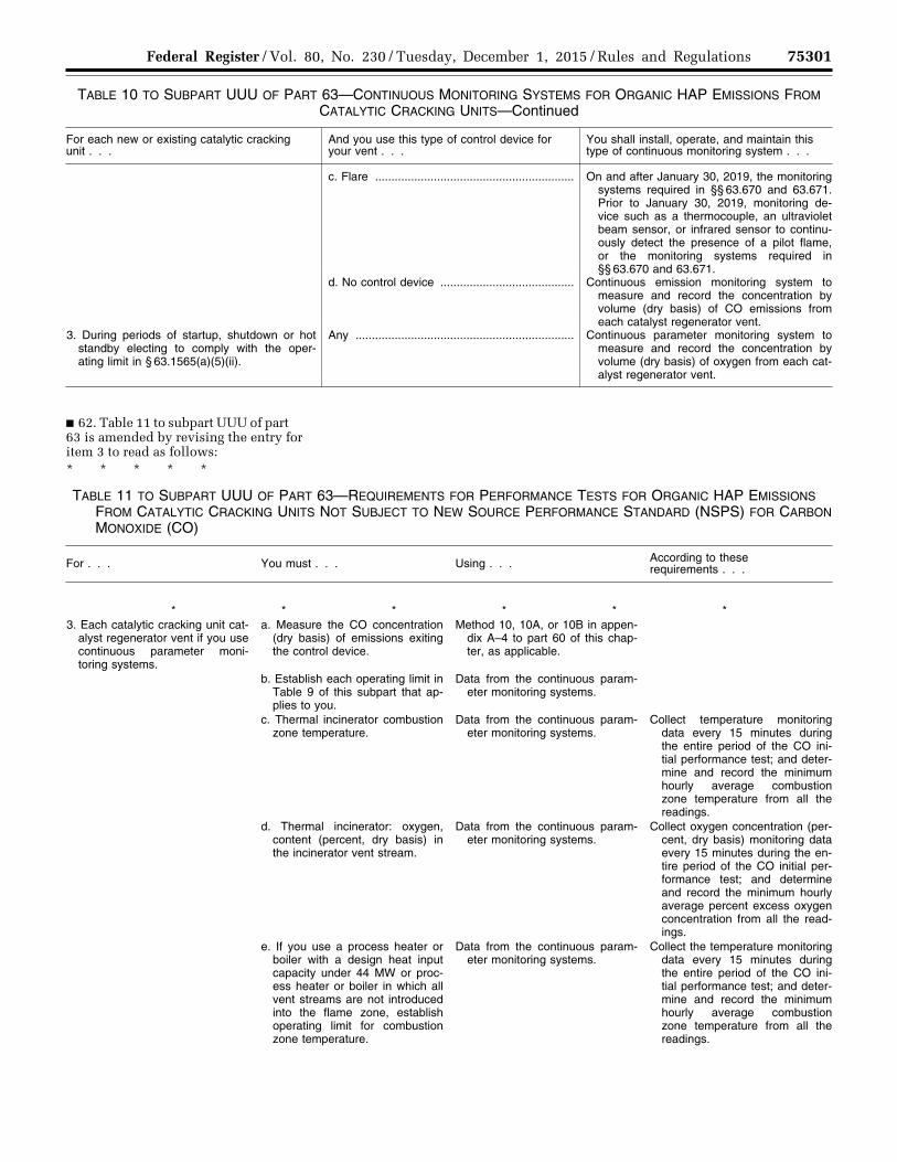
75301 Federal Register / Vol. 80, No. 230 / Tuesday, December 1, 2015 / Rules and Regulations
TABLE 10 TO SUBPART UUU OF PART 63—CONTINUOUS MONITORING SYSTEMS FOR ORGANIC HAP EMISSIONS FROM CATALYTIC CRACKING UNITS—Continued
For each new or existing catalytic cracking unit . . .
And you use this type of control device for your vent . . .
You shall install, operate, and maintain this type of continuous monitoring system . . .
c. Flare ............................................................. On and after January 30, 2019, the monitoring systems required in §§ 63.670 and 63.671. Prior to January 30, 2019, monitoring de-vice such as a thermocouple, an ultraviolet beam sensor, or infrared sensor to continu-ously detect the presence of a pilot flame, or the monitoring systems required in §§ 63.670 and 63.671.
d. No control device ......................................... Continuous emission monitoring system to measure and record the concentration by volume (dry basis) of CO emissions from each catalyst regenerator vent.
3. During periods of startup, shutdown or hot standby electing to comply with the oper-ating limit in § 63.1565(a)(5)(ii).
Any ................................................................... Continuous parameter monitoring system to measure and record the concentration by volume (dry basis) of oxygen from each cat-alyst regenerator vent.
■ 62. Table 11 to subpart UUU of part 63 is amended by revising the entry for item 3 to read as follows: * * * * *
TABLE 11 TO SUBPART UUU OF PART 63—REQUIREMENTS FOR PERFORMANCE TESTS FOR ORGANIC HAP EMISSIONS FROM CATALYTIC CRACKING UNITS NOT SUBJECT TO NEW SOURCE PERFORMANCE STANDARD (NSPS) FOR CARBON MONOXIDE (CO)
For . . . You must . . . Using . . . According to these requirements . . .
* * * * * * 3. Each catalytic cracking unit cat-
alyst regenerator vent if you use continuous parameter moni-toring systems.
a. Measure the CO concentration (dry basis) of emissions exiting the control device.
Method 10, 10A, or 10B in appen-dix A–4 to part 60 of this chap-ter, as applicable.
b. Establish each operating limit in Table 9 of this subpart that ap-plies to you.
Data from the continuous param-eter monitoring systems.
c. Thermal incinerator combustion zone temperature.
Data from the continuous param-eter monitoring systems.
Collect temperature monitoring data every 15 minutes during the entire period of the CO ini-tial performance test; and deter-mine and record the minimum hourly average combustion zone temperature from all the readings.
d. Thermal incinerator: oxygen, content (percent, dry basis) in the incinerator vent stream.
Data from the continuous param-eter monitoring systems.
Collect oxygen concentration (per-cent, dry basis) monitoring data every 15 minutes during the en-tire period of the CO initial per-formance test; and determine and record the minimum hourly average percent excess oxygen concentration from all the read-ings.
e. If you use a process heater or boiler with a design heat input capacity under 44 MW or proc-ess heater or boiler in which all vent streams are not introduced into the flame zone, establish operating limit for combustion zone temperature.
Data from the continuous param-eter monitoring systems.
Collect the temperature monitoring data every 15 minutes during the entire period of the CO ini-tial performance test; and deter-mine and record the minimum hourly average combustion zone temperature from all the readings.
VerDate Sep<11>2014 23:11 Nov 30, 2015 Jkt 238001 PO 00000 Frm 00125 Fmt 4701 Sfmt 4700 E:\FR\FM\01DER2.SGM 01DER2tkel
ley
on D
SK
3SP
TV
N1P
RO
D w
ith R
ULE
S2
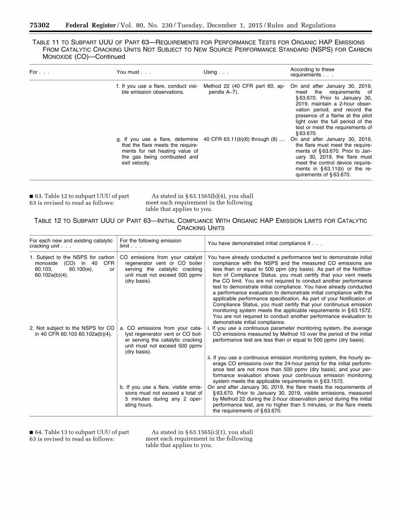
75302 Federal Register / Vol. 80, No. 230 / Tuesday, December 1, 2015 / Rules and Regulations
TABLE 11 TO SUBPART UUU OF PART 63—REQUIREMENTS FOR PERFORMANCE TESTS FOR ORGANIC HAP EMISSIONS FROM CATALYTIC CRACKING UNITS NOT SUBJECT TO NEW SOURCE PERFORMANCE STANDARD (NSPS) FOR CARBON MONOXIDE (CO)—Continued
For . . . You must . . . Using . . . According to these requirements . . .
f. If you use a flare, conduct visi-ble emission observations.
Method 22 (40 CFR part 60, ap-pendix A–7).
On and after January 30, 2019, meet the requirements of § 63.670. Prior to January 30, 2019, maintain a 2-hour obser-vation period; and record the presence of a flame at the pilot light over the full period of the test or meet the requirements of § 63.670.
g. If you use a flare, determine that the flare meets the require-ments for net heating value of the gas being combusted and exit velocity.
40 CFR 63.11(b)(6) through (8) .... On and after January 30, 2019, the flare must meet the require-ments of § 63.670. Prior to Jan-uary 30, 2019, the flare must meet the control device require-ments in § 63.11(b) or the re-quirements of § 63.670.
■ 63. Table 12 to subpart UUU of part 63 is revised to read as follows:
As stated in § 63.1565(b)(4), you shall meet each requirement in the following table that applies to you.
TABLE 12 TO SUBPART UUU OF PART 63—INITIAL COMPLIANCE WITH ORGANIC HAP EMISSION LIMITS FOR CATALYTIC CRACKING UNITS
For each new and existing catalytic cracking unit . . .
For the following emission limit . . . You have demonstrated initial compliance if . . .
1. Subject to the NSPS for carbon monoxide (CO) in 40 CFR 60.103, 60.100(e), or 60.102a(b)(4).
CO emissions from your catalyst regenerator vent or CO boiler serving the catalytic cracking unit must not exceed 500 ppmv (dry basis).
You have already conducted a performance test to demonstrate initial compliance with the NSPS and the measured CO emissions are less than or equal to 500 ppm (dry basis). As part of the Notifica-tion of Compliance Status, you must certify that your vent meets the CO limit. You are not required to conduct another performance test to demonstrate initial compliance. You have already conducted a performance evaluation to demonstrate initial compliance with the applicable performance specification. As part of your Notification of Compliance Status, you must certify that your continuous emission monitoring system meets the applicable requirements in § 63.1572. You are not required to conduct another performance evaluation to demonstrate initial compliance.
2. Not subject to the NSPS for CO in 40 CFR 60.103 60.102a(b)(4).
a. CO emissions from your cata-lyst regenerator vent or CO boil-er serving the catalytic cracking unit must not exceed 500 ppmv (dry basis).
i. If you use a continuous parameter monitoring system, the average CO emissions measured by Method 10 over the period of the initial performance test are less than or equal to 500 ppmv (dry basis).
ii. If you use a continuous emission monitoring system, the hourly av-erage CO emissions over the 24-hour period for the initial perform-ance test are not more than 500 ppmv (dry basis); and your per-formance evaluation shows your continuous emission monitoring system meets the applicable requirements in § 63.1572.
b. If you use a flare, visible emis-sions must not exceed a total of 5 minutes during any 2 oper-ating hours.
On and after January 30, 2019, the flare meets the requirements of § 63.670. Prior to January 30, 2019, visible emissions, measured by Method 22 during the 2-hour observation period during the initial performance test, are no higher than 5 minutes, or the flare meets the requirements of § 63.670.
■ 64. Table 13 to subpart UUU of part 63 is revised to read as follows:
As stated in § 63.1565(c)(1), you shall meet each requirement in the following table that applies to you.
VerDate Sep<11>2014 23:11 Nov 30, 2015 Jkt 238001 PO 00000 Frm 00126 Fmt 4701 Sfmt 4700 E:\FR\FM\01DER2.SGM 01DER2tkel
ley
on D
SK
3SP
TV
N1P
RO
D w
ith R
ULE
S2
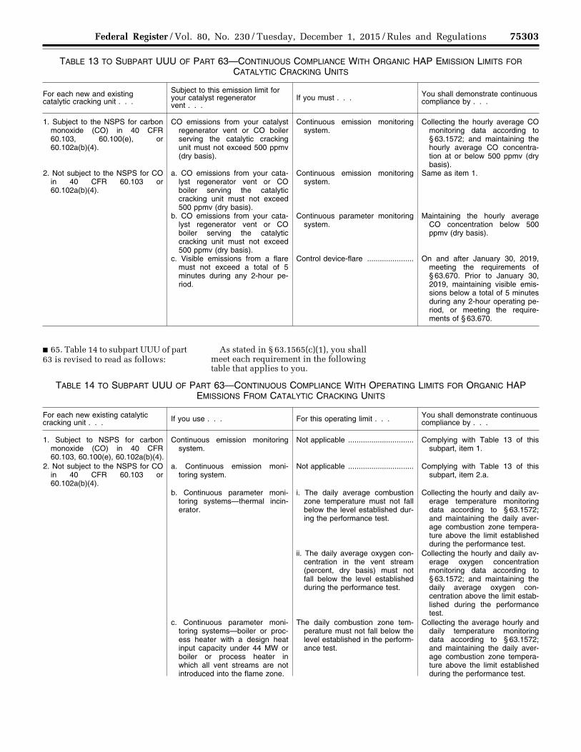
75303 Federal Register / Vol. 80, No. 230 / Tuesday, December 1, 2015 / Rules and Regulations
TABLE 13 TO SUBPART UUU OF PART 63—CONTINUOUS COMPLIANCE WITH ORGANIC HAP EMISSION LIMITS FOR CATALYTIC CRACKING UNITS
For each new and existing catalytic cracking unit . . .
Subject to this emission limit for your catalyst regenerator vent . . .
If you must . . . You shall demonstrate continuous compliance by . . .
1. Subject to the NSPS for carbon monoxide (CO) in 40 CFR 60.103, 60.100(e), or 60.102a(b)(4).
CO emissions from your catalyst regenerator vent or CO boiler serving the catalytic cracking unit must not exceed 500 ppmv (dry basis).
Continuous emission monitoring system.
Collecting the hourly average CO monitoring data according to § 63.1572; and maintaining the hourly average CO concentra-tion at or below 500 ppmv (dry basis).
2. Not subject to the NSPS for CO in 40 CFR 60.103 or 60.102a(b)(4).
a. CO emissions from your cata-lyst regenerator vent or CO boiler serving the catalytic cracking unit must not exceed 500 ppmv (dry basis).
Continuous emission monitoring system.
Same as item 1.
b. CO emissions from your cata-lyst regenerator vent or CO boiler serving the catalytic cracking unit must not exceed 500 ppmv (dry basis).
Continuous parameter monitoring system.
Maintaining the hourly average CO concentration below 500 ppmv (dry basis).
c. Visible emissions from a flare must not exceed a total of 5 minutes during any 2-hour pe-riod.
Control device-flare ...................... On and after January 30, 2019, meeting the requirements of § 63.670. Prior to January 30, 2019, maintaining visible emis-sions below a total of 5 minutes during any 2-hour operating pe-riod, or meeting the require-ments of § 63.670.
■ 65. Table 14 to subpart UUU of part 63 is revised to read as follows:
As stated in § 63.1565(c)(1), you shall meet each requirement in the following table that applies to you.
TABLE 14 TO SUBPART UUU OF PART 63—CONTINUOUS COMPLIANCE WITH OPERATING LIMITS FOR ORGANIC HAP EMISSIONS FROM CATALYTIC CRACKING UNITS
For each new existing catalytic cracking unit . . . If you use . . . For this operating limit . . . You shall demonstrate continuous
compliance by . . .
1. Subject to NSPS for carbon monoxide (CO) in 40 CFR 60.103, 60.100(e), 60.102a(b)(4).
Continuous emission monitoring system.
Not applicable ............................... Complying with Table 13 of this subpart, item 1.
2. Not subject to the NSPS for CO in 40 CFR 60.103 or 60.102a(b)(4).
a. Continuous emission moni-toring system.
Not applicable ............................... Complying with Table 13 of this subpart, item 2.a.
b. Continuous parameter moni-toring systems—thermal incin-erator.
i. The daily average combustion zone temperature must not fall below the level established dur-ing the performance test.
Collecting the hourly and daily av-erage temperature monitoring data according to § 63.1572; and maintaining the daily aver-age combustion zone tempera-ture above the limit established during the performance test.
ii. The daily average oxygen con-centration in the vent stream (percent, dry basis) must not fall below the level established during the performance test.
Collecting the hourly and daily av-erage oxygen concentration monitoring data according to § 63.1572; and maintaining the daily average oxygen con-centration above the limit estab-lished during the performance test.
c. Continuous parameter moni-toring systems—boiler or proc-ess heater with a design heat input capacity under 44 MW or boiler or process heater in which all vent streams are not introduced into the flame zone.
The daily combustion zone tem-perature must not fall below the level established in the perform-ance test.
Collecting the average hourly and daily temperature monitoring data according to § 63.1572; and maintaining the daily aver-age combustion zone tempera-ture above the limit established during the performance test.
VerDate Sep<11>2014 23:11 Nov 30, 2015 Jkt 238001 PO 00000 Frm 00127 Fmt 4701 Sfmt 4700 E:\FR\FM\01DER2.SGM 01DER2tkel
ley
on D
SK
3SP
TV
N1P
RO
D w
ith R
ULE
S2
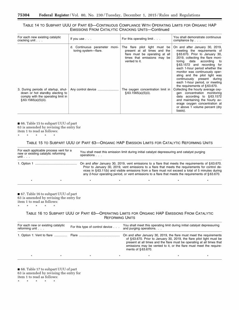
75304 Federal Register / Vol. 80, No. 230 / Tuesday, December 1, 2015 / Rules and Regulations
TABLE 14 TO SUBPART UUU OF PART 63—CONTINUOUS COMPLIANCE WITH OPERATING LIMITS FOR ORGANIC HAP EMISSIONS FROM CATALYTIC CRACKING UNITS—Continued
For each new existing catalytic cracking unit . . . If you use . . . For this operating limit . . . You shall demonstrate continuous
compliance by . . .
d. Continuous parameter moni-toring system—flare.
The flare pilot light must be present at all times and the flare must be operating at all times that emissions may be vented to it.
On and after January 30, 2019, meeting the requirements of § 63.670. Prior to January 30, 2019, collecting the flare moni-toring data according to § 63.1572 and recording for each 1-hour period whether the monitor was continuously oper-ating and the pilot light was continuously present during each 1-hour period, or meeting the requirements of § 63.670.
3. During periods of startup, shut-down or hot standby electing to comply with the operating limit in § 63.1565(a)(5)(ii).
Any control device ........................ The oxygen concentration limit in § 63.1565(a)(5)(ii).
Collecting the hourly average oxy-gen concentration monitoring data according to § 63.1572 and maintaining the hourly av-erage oxygen concentration at or above 1 volume percent (dry basis).
■ 66. Table 15 to subpart UUU of part 63 is amended by revising the entry for item 1 to read as follows: * * * * *
TABLE 15 TO SUBPART UUU OF PART 63—ORGANIC HAP EMISSION LIMITS FOR CATALYTIC REFORMING UNITS
For each applicable process vent for a new or existing catalytic reforming unit . . .
You shall meet this emission limit during initial catalyst depressuring and catalyst purging operations . . .
1. Option 1 ................................................ On and after January 30, 2019, vent emissions to a flare that meets the requirements of § 63.670. Prior to January 30, 2019, vent emissions to a flare that meets the requirements for control de-vices in § 63.11(b) and visible emissions from a flare must not exceed a total of 5 minutes during any 2-hour operating period, or vent emissions to a flare that meets the requirements of § 63.670.
* * * * * * *
■ 67. Table 16 to subpart UUU of part 63 is amended by revising the entry for item 1 to read as follows: * * * * *
TABLE 16 TO SUBPART UUU OF PART 63—OPERATING LIMITS FOR ORGANIC HAP EMISSIONS FROM CATALYTIC REFORMING UNITS
For each new or existing catalytic reforming unit . . . For this type of control device . . . You shall meet this operating limit during initial catalyst depressuring
and purging operations. . .
1. Option 1: Vent to flare ............... Flare ............................................... On and after January 30, 2019, the flare must meet the requirements of § 63.670. Prior to January 30, 2019, the flare pilot light must be present at all times and the flare must be operating at all times that emissions may be vented to it, or the flare must meet the require-ments of § 63.670.
* * * * * * *
■ 68. Table 17 to subpart UUU of part 63 is amended by revising the entry for item 1 to read as follows: * * * * *
VerDate Sep<11>2014 23:11 Nov 30, 2015 Jkt 238001 PO 00000 Frm 00128 Fmt 4701 Sfmt 4700 E:\FR\FM\01DER2.SGM 01DER2tkel
ley
on D
SK
3SP
TV
N1P
RO
D w
ith R
ULE
S2

75305 Federal Register / Vol. 80, No. 230 / Tuesday, December 1, 2015 / Rules and Regulations
TABLE 17 TO SUBPART UUU OF PART 63—CONTINUOUS MONITORING SYSTEMS FOR ORGANIC HAP EMISSIONS FROM CATALYTIC REFORMING UNITS
For each applicable process vent for a new or existing catalytic reforming unit . . .
If you use this type of control device . . .
You shall install and operate this type of continuous monitoring system . . .
1. Option 1: Vent to a flare ............ Flare ............................................... On and after January 30, 2019, the monitoring systems required in §§ 63.670 and 63.671. Prior to January 30, 2019, monitoring device such as a thermocouple, an ultraviolet beam sensor, or infrared sensor to continuously detect the presence of a pilot flame, or the monitoring systems required in §§ 63.670 and 63.671.
* * * * * * *
■ 69. Table 18 to subpart UUU of part 63 is amended by revising the column
headings and the entry for item 1 to read as follows: * * * * *
TABLE 18 TO SUBPART UUU OF PART 63—REQUIREMENTS FOR PERFORMANCE TESTS FOR ORGANIC HAP EMISSIONS FROM CATALYTIC REFORMING UNITS
For each new or existing catalytic reforming unit . . . You must . . . Using . . . According to these
requirements . . .
1. Option 1: Vent to a flare ........... a. Conduct visible emission obser-vations.
Method 22 (40 CFR part 60, ap-pendix A–7).
On and after January 30, 2019, the flare must meet the require-ments of § 63.670. Prior to Jan-uary 30, 2019, 2-hour observa-tion period. Record the pres-ence of a flame at the pilot light over the full period of the test, or the requirements of § 63.670.
b. Determine that the flare meets the requirements for net heating value of the gas being com-busted and exit velocity.
40 CFR 63.11(b)(6) through (8) .... On and after January 30, 2019, the flare must meet the require-ments of § 63.670. Prior to Jan-uary 30, 2019, the flare must meet the control device require-ments in § 63.11(b) or the re-quirements of § 63.670.
* * * * * * *
■ 70. Table 19 to subpart UUU of part 63 is amended by revising the entry for item 1 to read as follows: * * * * *
TABLE 19 TO SUBPART UUU OF PART 63—INITIAL COMPLIANCE WITH ORGANIC HAP EMISSION LIMITS FOR CATALYTIC REFORMING UNITS
For each applicable process vent for a new or existing catalytic reforming unit . . . For the following emission limit . . . You have demonstrated initial compliance
if . . .
Option 1 ............................................................ Visible emissions from a flare must not exceed a total of 5 minutes during any 2 consecu-tive hours.
On and after January 30, 2019, the flare meets the requirements of § 63.670. Prior to January 30, 2019, visible emissions, meas-ured using Method 22 over the 2-hour ob-servation period of the performance test, do not exceed a total of 5 minutes, or the flare meets the requirements of § 63.670.
* * * * * * *
■ 71. Table 20 to subpart UUU of part 63 is amended by revising the entry for item 1 to read as follows: * * * * *
VerDate Sep<11>2014 23:11 Nov 30, 2015 Jkt 238001 PO 00000 Frm 00129 Fmt 4701 Sfmt 4700 E:\FR\FM\01DER2.SGM 01DER2tkel
ley
on D
SK
3SP
TV
N1P
RO
D w
ith R
ULE
S2
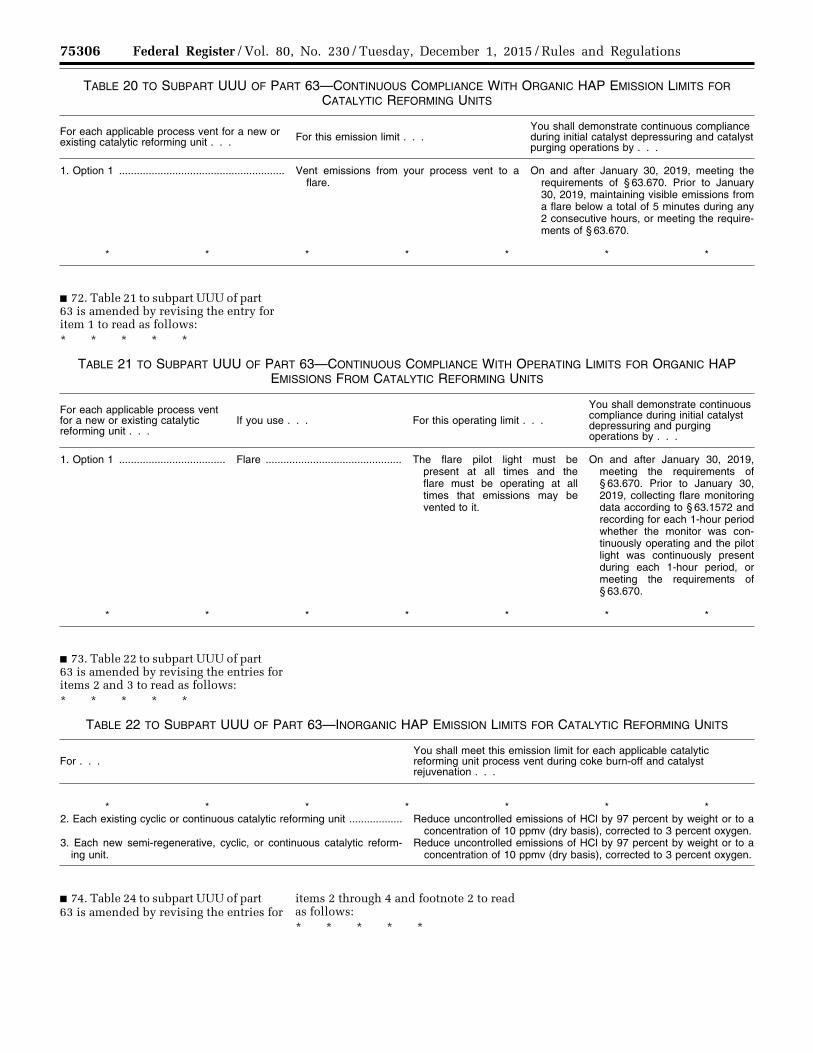
75306 Federal Register / Vol. 80, No. 230 / Tuesday, December 1, 2015 / Rules and Regulations
TABLE 20 TO SUBPART UUU OF PART 63—CONTINUOUS COMPLIANCE WITH ORGANIC HAP EMISSION LIMITS FOR CATALYTIC REFORMING UNITS
For each applicable process vent for a new or existing catalytic reforming unit . . . For this emission limit . . .
You shall demonstrate continuous compliance during initial catalyst depressuring and catalyst purging operations by . . .
1. Option 1 ........................................................ Vent emissions from your process vent to a flare.
On and after January 30, 2019, meeting the requirements of § 63.670. Prior to January 30, 2019, maintaining visible emissions from a flare below a total of 5 minutes during any 2 consecutive hours, or meeting the require-ments of § 63.670.
* * * * * * *
■ 72. Table 21 to subpart UUU of part 63 is amended by revising the entry for item 1 to read as follows: * * * * *
TABLE 21 TO SUBPART UUU OF PART 63—CONTINUOUS COMPLIANCE WITH OPERATING LIMITS FOR ORGANIC HAP EMISSIONS FROM CATALYTIC REFORMING UNITS
For each applicable process vent for a new or existing catalytic reforming unit . . .
If you use . . . For this operating limit . . .
You shall demonstrate continuous compliance during initial catalyst depressuring and purging operations by . . .
1. Option 1 .................................... Flare .............................................. The flare pilot light must be present at all times and the flare must be operating at all times that emissions may be vented to it.
On and after January 30, 2019, meeting the requirements of § 63.670. Prior to January 30, 2019, collecting flare monitoring data according to § 63.1572 and recording for each 1-hour period whether the monitor was con-tinuously operating and the pilot light was continuously present during each 1-hour period, or meeting the requirements of § 63.670.
* * * * * * *
■ 73. Table 22 to subpart UUU of part 63 is amended by revising the entries for items 2 and 3 to read as follows: * * * * *
TABLE 22 TO SUBPART UUU OF PART 63—INORGANIC HAP EMISSION LIMITS FOR CATALYTIC REFORMING UNITS
For . . . You shall meet this emission limit for each applicable catalytic reforming unit process vent during coke burn-off and catalyst rejuvenation . . .
* * * * * * * 2. Each existing cyclic or continuous catalytic reforming unit .................. Reduce uncontrolled emissions of HCl by 97 percent by weight or to a
concentration of 10 ppmv (dry basis), corrected to 3 percent oxygen. 3. Each new semi-regenerative, cyclic, or continuous catalytic reform-
ing unit.Reduce uncontrolled emissions of HCl by 97 percent by weight or to a
concentration of 10 ppmv (dry basis), corrected to 3 percent oxygen.
■ 74. Table 24 to subpart UUU of part 63 is amended by revising the entries for
items 2 through 4 and footnote 2 to read as follows: * * * * *
VerDate Sep<11>2014 23:11 Nov 30, 2015 Jkt 238001 PO 00000 Frm 00130 Fmt 4701 Sfmt 4700 E:\FR\FM\01DER2.SGM 01DER2tkel
ley
on D
SK
3SP
TV
N1P
RO
D w
ith R
ULE
S2
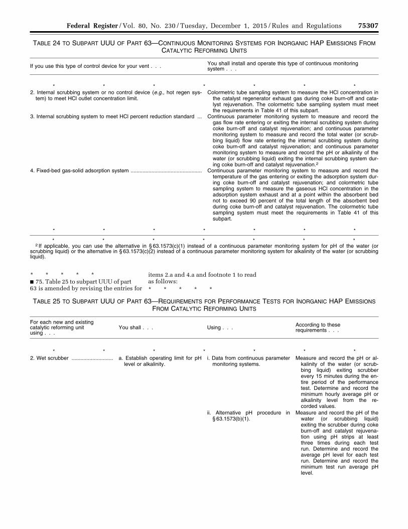
75307 Federal Register / Vol. 80, No. 230 / Tuesday, December 1, 2015 / Rules and Regulations
TABLE 24 TO SUBPART UUU OF PART 63—CONTINUOUS MONITORING SYSTEMS FOR INORGANIC HAP EMISSIONS FROM CATALYTIC REFORMING UNITS
If you use this type of control device for your vent . . . You shall install and operate this type of continuous monitoring system . . .
* * * * * * * 2. Internal scrubbing system or no control device (e.g., hot regen sys-
tem) to meet HCl outlet concentration limit.Colormetric tube sampling system to measure the HCl concentration in
the catalyst regenerator exhaust gas during coke burn-off and cata-lyst rejuvenation. The colormetric tube sampling system must meet the requirements in Table 41 of this subpart.
3. Internal scrubbing system to meet HCl percent reduction standard ... Continuous parameter monitoring system to measure and record the gas flow rate entering or exiting the internal scrubbing system during coke burn-off and catalyst rejuvenation; and continuous parameter monitoring system to measure and record the total water (or scrub-bing liquid) flow rate entering the internal scrubbing system during coke burn-off and catalyst rejuvenation; and continuous parameter monitoring system to measure and record the pH or alkalinity of the water (or scrubbing liquid) exiting the internal scrubbing system dur-ing coke burn-off and catalyst rejuvenation.2
4. Fixed-bed gas-solid adsorption system ................................................ Continuous parameter monitoring system to measure and record the temperature of the gas entering or exiting the adsorption system dur-ing coke burn-off and catalyst rejuvenation; and colormetric tube sampling system to measure the gaseous HCl concentration in the adsorption system exhaust and at a point within the absorbent bed not to exceed 90 percent of the total length of the absorbent bed during coke burn-off and catalyst rejuvenation. The colormetric tube sampling system must meet the requirements in Table 41 of this subpart.
* * * * * * *
* * * * * * * 2 If applicable, you can use the alternative in § 63.1573(c)(1) instead of a continuous parameter monitoring system for pH of the water (or
scrubbing liquid) or the alternative in § 63.1573(c)(2) instead of a continuous parameter monitoring system for alkalinity of the water (or scrubbing liquid).
* * * * * ■ 75. Table 25 to subpart UUU of part 63 is amended by revising the entries for
items 2.a and 4.a and footnote 1 to read as follows: * * * * *
TABLE 25 TO SUBPART UUU OF PART 63—REQUIREMENTS FOR PERFORMANCE TESTS FOR INORGANIC HAP EMISSIONS FROM CATALYTIC REFORMING UNITS
For each new and existing catalytic reforming unit using . . .
You shall . . . Using . . . According to these requirements . . .
* * * * * * * 2. Wet scrubber ............................ a. Establish operating limit for pH
level or alkalinity.i. Data from continuous parameter
monitoring systems.Measure and record the pH or al-
kalinity of the water (or scrub-bing liquid) exiting scrubber every 15 minutes during the en-tire period of the performance test. Determine and record the minimum hourly average pH or alkalinity level from the re-corded values.
ii. Alternative pH procedure in § 63.1573(b)(1).
Measure and record the pH of the water (or scrubbing liquid) exiting the scrubber during coke burn-off and catalyst rejuvena-tion using pH strips at least three times during each test run. Determine and record the average pH level for each test run. Determine and record the minimum test run average pH level.
VerDate Sep<11>2014 23:11 Nov 30, 2015 Jkt 238001 PO 00000 Frm 00131 Fmt 4701 Sfmt 4700 E:\FR\FM\01DER2.SGM 01DER2tkel
ley
on D
SK
3SP
TV
N1P
RO
D w
ith R
ULE
S2
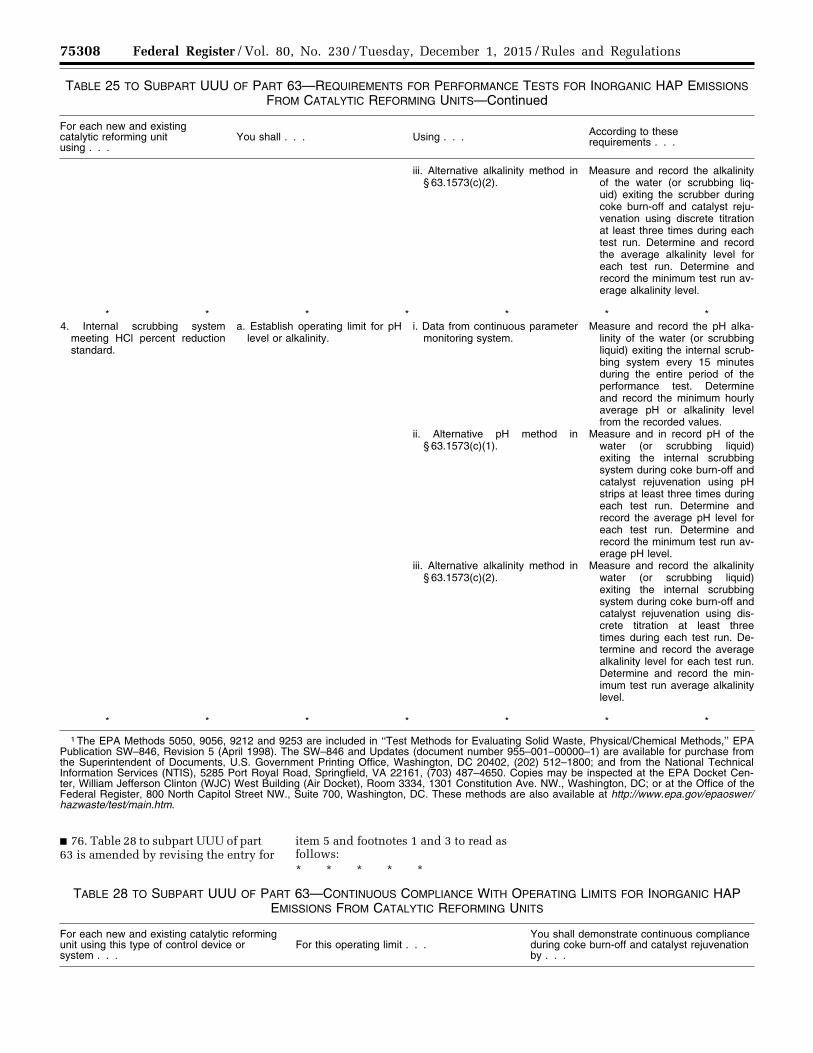
75308 Federal Register / Vol. 80, No. 230 / Tuesday, December 1, 2015 / Rules and Regulations
TABLE 25 TO SUBPART UUU OF PART 63—REQUIREMENTS FOR PERFORMANCE TESTS FOR INORGANIC HAP EMISSIONS FROM CATALYTIC REFORMING UNITS—Continued
For each new and existing catalytic reforming unit using . . .
You shall . . . Using . . . According to these requirements . . .
iii. Alternative alkalinity method in § 63.1573(c)(2).
Measure and record the alkalinity of the water (or scrubbing liq-uid) exiting the scrubber during coke burn-off and catalyst reju-venation using discrete titration at least three times during each test run. Determine and record the average alkalinity level for each test run. Determine and record the minimum test run av-erage alkalinity level.
* * * * * * * 4. Internal scrubbing system
meeting HCl percent reduction standard.
a. Establish operating limit for pH level or alkalinity.
i. Data from continuous parameter monitoring system.
Measure and record the pH alka-linity of the water (or scrubbing liquid) exiting the internal scrub-bing system every 15 minutes during the entire period of the performance test. Determine and record the minimum hourly average pH or alkalinity level from the recorded values.
ii. Alternative pH method in § 63.1573(c)(1).
Measure and in record pH of the water (or scrubbing liquid) exiting the internal scrubbing system during coke burn-off and catalyst rejuvenation using pH strips at least three times during each test run. Determine and record the average pH level for each test run. Determine and record the minimum test run av-erage pH level.
iii. Alternative alkalinity method in § 63.1573(c)(2).
Measure and record the alkalinity water (or scrubbing liquid) exiting the internal scrubbing system during coke burn-off and catalyst rejuvenation using dis-crete titration at least three times during each test run. De-termine and record the average alkalinity level for each test run. Determine and record the min-imum test run average alkalinity level.
* * * * * * *
1 The EPA Methods 5050, 9056, 9212 and 9253 are included in ‘‘Test Methods for Evaluating Solid Waste, Physical/Chemical Methods,’’ EPA Publication SW–846, Revision 5 (April 1998). The SW–846 and Updates (document number 955–001–00000–1) are available for purchase from the Superintendent of Documents, U.S. Government Printing Office, Washington, DC 20402, (202) 512–1800; and from the National Technical Information Services (NTIS), 5285 Port Royal Road, Springfield, VA 22161, (703) 487–4650. Copies may be inspected at the EPA Docket Cen-ter, William Jefferson Clinton (WJC) West Building (Air Docket), Room 3334, 1301 Constitution Ave. NW., Washington, DC; or at the Office of the Federal Register, 800 North Capitol Street NW., Suite 700, Washington, DC. These methods are also available at http://www.epa.gov/epaoswer/hazwaste/test/main.htm.
■ 76. Table 28 to subpart UUU of part 63 is amended by revising the entry for
item 5 and footnotes 1 and 3 to read as follows: * * * * *
TABLE 28 TO SUBPART UUU OF PART 63—CONTINUOUS COMPLIANCE WITH OPERATING LIMITS FOR INORGANIC HAP EMISSIONS FROM CATALYTIC REFORMING UNITS
For each new and existing catalytic reforming unit using this type of control device or system . . .
For this operating limit . . . You shall demonstrate continuous compliance during coke burn-off and catalyst rejuvenation by . . .
VerDate Sep<11>2014 23:11 Nov 30, 2015 Jkt 238001 PO 00000 Frm 00132 Fmt 4701 Sfmt 4700 E:\FR\FM\01DER2.SGM 01DER2tkel
ley
on D
SK
3SP
TV
N1P
RO
D w
ith R
ULE
S2
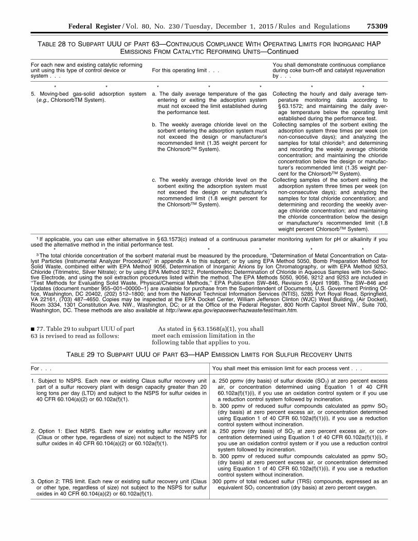
75309 Federal Register / Vol. 80, No. 230 / Tuesday, December 1, 2015 / Rules and Regulations
TABLE 28 TO SUBPART UUU OF PART 63—CONTINUOUS COMPLIANCE WITH OPERATING LIMITS FOR INORGANIC HAP EMISSIONS FROM CATALYTIC REFORMING UNITS—Continued
For each new and existing catalytic reforming unit using this type of control device or system . . .
For this operating limit . . . You shall demonstrate continuous compliance during coke burn-off and catalyst rejuvenation by . . .
* * * * * * * 5. Moving-bed gas-solid adsorption system
(e.g., ChlorsorbTM System).a. The daily average temperature of the gas
entering or exiting the adsorption system must not exceed the limit established during the performance test.
Collecting the hourly and daily average tem-perature monitoring data according to § 63.1572; and maintaining the daily aver-age temperature below the operating limit established during the performance test.
b. The weekly average chloride level on the sorbent entering the adsorption system must not exceed the design or manufacturer’s recommended limit (1.35 weight percent for the ChlorsorbTM System).
Collecting samples of the sorbent exiting the adsorption system three times per week (on non-consecutive days); and analyzing the samples for total chloride3; and determining and recording the weekly average chloride concentration; and maintaining the chloride concentration below the design or manufac-turer’s recommended limit (1.35 weight per-cent for the ChlorsorbTM System).
c. The weekly average chloride level on the sorbent exiting the adsorption system must not exceed the design or manufacturer’s recommended limit (1.8 weight percent for the ChlorsorbTM System).
Collecting samples of the sorbent exiting the adsorption system three times per week (on non-consecutive days); and analyzing the samples for total chloride concentration; and determining and recording the weekly aver-age chloride concentration; and maintaining the chloride concentration below the design or manufacturer’s recommended limit (1.8 weight percent ChlorsorbTM System).
1 If applicable, you can use either alternative in § 63.1573(c) instead of a continuous parameter monitoring system for pH or alkalinity if you used the alternative method in the initial performance test.
* * * * * * * 3 The total chloride concentration of the sorbent material must be measured by the procedure, ‘‘Determination of Metal Concentration on Cata-
lyst Particles (Instrumental Analyzer Procedure)’’ in appendix A to this subpart; or by using EPA Method 5050, Bomb Preparation Method for Solid Waste, combined either with EPA Method 9056, Determination of Inorganic Anions by Ion Chromatography, or with EPA Method 9253, Chloride (Titrimetric, Silver Nitrate); or by using EPA Method 9212, Potentiometric Determination of Chloride in Aqueous Samples with Ion-Selec-tive Electrode, and using the soil extraction procedures listed within the method. The EPA Methods 5050, 9056, 9212 and 9253 are included in ‘‘Test Methods for Evaluating Solid Waste, Physical/Chemical Methods,’’ EPA Publication SW–846, Revision 5 (April 1998). The SW–846 and Updates (document number 955–001–00000–1) are available for purchase from the Superintendent of Documents, U.S. Government Printing Of-fice, Washington, DC 20402, (202) 512–1800; and from the National Technical Information Services (NTIS), 5285 Port Royal Road, Springfield, VA 22161, (703) 487–4650. Copies may be inspected at the EPA Docket Center, William Jefferson Clinton (WJC) West Building, (Air Docket), Room 3334, 1301 Constitution Ave. NW., Washington, DC; or at the Office of the Federal Register, 800 North Capitol Street NW., Suite 700, Washington, DC. These methods are also available at http://www.epa.gov/epaoswer/hazwaste/test/main.htm.
■ 77. Table 29 to subpart UUU of part 63 is revised to read as follows:
As stated in § 63.1568(a)(1), you shall meet each emission limitation in the following table that applies to you.
TABLE 29 TO SUBPART UUU OF PART 63—HAP EMISSION LIMITS FOR SULFUR RECOVERY UNITS
For . . . You shall meet this emission limit for each process vent . . .
1. Subject to NSPS. Each new or existing Claus sulfur recovery unit part of a sulfur recovery plant with design capacity greater than 20 long tons per day (LTD) and subject to the NSPS for sulfur oxides in 40 CFR 60.104(a)(2) or 60.102a(f)(1).
a. 250 ppmv (dry basis) of sulfur dioxide (SO2) at zero percent excess air, or concentration determined using Equation 1 of 40 CFR 60.102a(f)(1)(i), if you use an oxidation control system or if you use a reduction control system followed by incineration.
b. 300 ppmv of reduced sulfur compounds calculated as ppmv SO2 (dry basis) at zero percent excess air, or concentration determined using Equation 1 of 40 CFR 60.102a(f)(1)(i), if you use a reduction control system without incineration.
2. Option 1: Elect NSPS. Each new or existing sulfur recovery unit (Claus or other type, regardless of size) not subject to the NSPS for sulfur oxides in 40 CFR 60.104(a)(2) or 60.102a(f)(1).
a. 250 ppmv (dry basis) of SO2 at zero percent excess air, or con-centration determined using Equation 1 of 40 CFR 60.102a(f)(1)(i), if you use an oxidation control system or if you use a reduction control system followed by incineration.
b. 300 ppmv of reduced sulfur compounds calculated as ppmv SO2 (dry basis) at zero percent excess air, or concentration determined using Equation 1 of 40 CFR 60.102a(f)(1)(i), if you use a reduction control system without incineration.
3. Option 2: TRS limit. Each new or existing sulfur recovery unit (Claus or other type, regardless of size) not subject to the NSPS for sulfur oxides in 40 CFR 60.104(a)(2) or 60.102a(f)(1).
300 ppmv of total reduced sulfur (TRS) compounds, expressed as an equivalent SO2 concentration (dry basis) at zero percent oxygen.
VerDate Sep<11>2014 23:11 Nov 30, 2015 Jkt 238001 PO 00000 Frm 00133 Fmt 4701 Sfmt 4700 E:\FR\FM\01DER2.SGM 01DER2tkel
ley
on D
SK
3SP
TV
N1P
RO
D w
ith R
ULE
S2
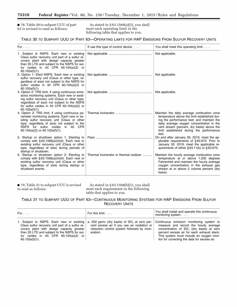
75310 Federal Register / Vol. 80, No. 230 / Tuesday, December 1, 2015 / Rules and Regulations
■ 78. Table 30 to subpart UUU of part 63 is revised to read as follows:
As stated in § 63.1568(a)(2), you shall meet each operating limit in the following table that applies to you.
TABLE 30 TO SUBPART UUU OF PART 63—OPERATING LIMITS FOR HAP EMISSIONS FROM SULFUR RECOVERY UNITS
For . . . If use this type of control device . . . You shall meet this operating limit . . .
1. Subject to NSPS. Each new or existing Claus sulfur recovery unit part of a sulfur re-covery plant with design capacity greater than 20 LTD and subject to the NSPS for sul-fur oxides in 40 CFR 60.104(a)(2) or 60.102a(f)(1).
Not applicable .................................................. Not applicable.
2. Option 1: Elect NSPS. Each new or existing sulfur recovery unit (Claus or other type, re-gardless of size) not subject to the NSPS for sulfur oxides in 40 CFR 60.104(a)(2) or 60.102a(f)(1).
Not applicable .................................................. Not applicable.
3. Option 2: TRS limit, if using continuous emis-sions monitoring systems. Each new or exist-ing sulfur recovery unit (Claus or other type, regardless of size) not subject to the NSPS for sulfur oxides in 40 CFR 60.104(a)(2) or 60.102a(f)(1).
Not applicable .................................................. Not applicable.
4. Option 2: TRS limit, if using continuous pa-rameter monitoring systems. Each new or ex-isting sulfur recovery unit (Claus or other type, regardless of size) not subject to the NSPS for sulfur oxides in 40 CFR 60.104(a)(2) or 60.102a(f)(1).
Thermal incinerator .......................................... Maintain the daily average combustion zone temperature above the limit established dur-ing the performance test; and maintain the daily average oxygen concentration in the vent stream (percent, dry basis) above the limit established during the performance test.
5. Startup or shutdown option 1: Electing to comply with § 63.1568(a)(4)(ii). Each new or existing sulfur recovery unit (Claus or other type, regardless of size) during periods of startup or shutdown.
Flare ................................................................. On and after January 30, 2019, meet the ap-plicable requirements of § 63.670. Prior to January 30, 2019, meet the applicable re-quirements of either § 63.11(b) or § 63.670.
6. Startup or shutdown option 2: Electing to comply with § 63.1568(a)(4)(iii). Each new or existing sulfur recovery unit (Claus or other type, regardless of size) during startup or shutdown events.
Thermal incinerator or thermal oxidizer ........... Maintain the hourly average combustion zone temperature at or above 1,200 degrees Fahrenheit and maintain the hourly average oxygen concentration in the exhaust gas stream at or above 2 volume percent (dry basis).
■ 79. Table 31 to subpart UUU is revised to read as follows:
As stated in § 63.1568(b)(1), you shall meet each requirement in the following table that applies to you.
TABLE 31 TO SUBPART UUU OF PART 63—CONTINUOUS MONITORING SYSTEMS FOR HAP EMISSIONS FROM SULFUR RECOVERY UNITS
For . . . For this limit . . . You shall install and operate this continuous monitoring system . . .
1. Subject to NSPS. Each new or existing Claus sulfur recovery unit part of a sulfur re-covery plant with design capacity greater than 20 LTD and subject to the NSPS for sul-fur oxides in 40 CFR 60.104(a)(2) or 60.102a(f)(1).
a. 250 ppmv (dry basis) of SO2 at zero per-cent excess air if you use an oxidation or reduction control system followed by incin-eration.
Continuous emission monitoring system to measure and record the hourly average concentration of SO2 (dry basis) at zero percent excess air for each exhaust stack. This system must include an oxygen mon-itor for correcting the data for excess air.
VerDate Sep<11>2014 23:11 Nov 30, 2015 Jkt 238001 PO 00000 Frm 00134 Fmt 4701 Sfmt 4700 E:\FR\FM\01DER2.SGM 01DER2tkel
ley
on D
SK
3SP
TV
N1P
RO
D w
ith R
ULE
S2

75311 Federal Register / Vol. 80, No. 230 / Tuesday, December 1, 2015 / Rules and Regulations
TABLE 31 TO SUBPART UUU OF PART 63—CONTINUOUS MONITORING SYSTEMS FOR HAP EMISSIONS FROM SULFUR RECOVERY UNITS—Continued
For . . . For this limit . . . You shall install and operate this continuous monitoring system . . .
b. 300 ppmv of reduced sulfur compounds calculated as ppmv SO2 (dry basis) at zero percent excess air if you use a reduction control system without incineration.
Continuous emission monitoring system to measure and record the hourly average concentration of reduced sulfur and oxygen (O2) emissions. Calculate the reduced sul-fur emissions as SO2 (dry basis) at zero percent excess air. Exception: You can use an instrument having an air or SO2 dilution and oxidation system to convert the re-duced sulfur to SO2 for continuously moni-toring and recording the concentration (dry basis) at zero percent excess air of the re-sultant SO2 instead of the reduced sulfur monitor. The monitor must include an oxy-gen monitor for correcting the data for ex-cess oxygen.
c. If you use Equation 1 of 40 CFR 60.102a(f)(1)(i) to set your emission limit.
i. Complete either item 1.a or item 1.b; and ii. Either a continuous emission monitoring
system to measure and record the O2 con-centration for the inlet air/oxygen supplied to the system or a continuous parameter monitoring system to measure and record the volumetric gas flow rate of ambient air and purchased oxygen-enriched gas.
2. Option 1: Elect NSPS. Each new or existing sulfur recovery unit (Claus or other type, re-gardless of size) not subject to the NSPS for sulfur oxides in 40 CFR 60.104(a)(2) or 60.102a(f)(1).
a. 250 ppmv (dry basis) of SO2 at zero per-cent excess air if you use an oxidation or reduction control system followed by incin-eration.
Continuous emission monitoring system to measure and record the hourly average concentration of SO2 (dry basis), at zero percent excess air for each exhaust stack. This system must include an oxygen mon-itor for correcting the data for excess air.
b. 300 ppmv of reduced sulfur compounds calculated as ppmv SO2 (dry basis) at zero percent excess air if you use a reduction control system without incineration.
Continuous emission monitoring system to measure and record the hourly average concentration of reduced sulfur and O2 emissions for each exhaust stack. Calculate the reduced sulfur emissions as SO2 (dry basis), at zero percent excess air. Excep-tion: You can use an instrument having an air or O2 dilution and oxidation system to convert the reduced sulfur to SO2 for con-tinuously monitoring and recording the con-centration (dry basis) at zero percent ex-cess air of the resultant SO2 instead of the reduced sulfur monitor. The monitor must include an oxygen monitor for correcting the data for excess oxygen.
c. If you use Equation 1 of 40 CFR 60.102a(f)(1)(i) to set your emission limit.
i. Complete either item 2.a or item 2.b; and ii. Either a continuous emission monitoring
system to measure and record the O2 con-centration for the inlet air/oxygen supplied to the system, or a continuous parameter monitoring system to measure and record the volumetric gas flow rate of ambient air and purchased oxygen-enriched gas.
3. Option 2: TRS limit. Each new or existing sulfur recovery unit (Claus or other type, re-gardless of size) not subject to the NSPS for sulfur oxides in 40 CFR 60.104(a)(2) or 60.102a(f)(1).
a. 300 ppmv of total reduced sulfur (TRS) compounds, expressed as an equivalent SO2 concentration (dry basis) at zero per-cent oxygen.
i. Continuous emission monitoring system to measure and record the hourly average concentration of TRS for each exhaust stack; this monitor must include an oxygen monitor for correcting the data for excess oxygen; or
ii. Continuous parameter monitoring systems to measure and record the combustion zone temperature of each thermal inciner-ator and the oxygen content (percent, dry basis) in the vent stream of the incinerator.
VerDate Sep<11>2014 23:11 Nov 30, 2015 Jkt 238001 PO 00000 Frm 00135 Fmt 4701 Sfmt 4700 E:\FR\FM\01DER2.SGM 01DER2tkel
ley
on D
SK
3SP
TV
N1P
RO
D w
ith R
ULE
S2
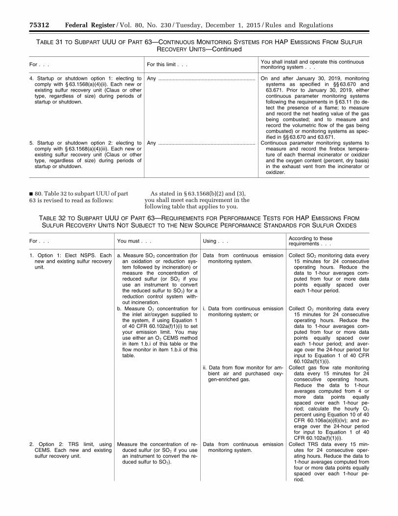
75312 Federal Register / Vol. 80, No. 230 / Tuesday, December 1, 2015 / Rules and Regulations
TABLE 31 TO SUBPART UUU OF PART 63—CONTINUOUS MONITORING SYSTEMS FOR HAP EMISSIONS FROM SULFUR RECOVERY UNITS—Continued
For . . . For this limit . . . You shall install and operate this continuous monitoring system . . .
4. Startup or shutdown option 1: electing to comply with § 63.1568(a)(4)(ii). Each new or existing sulfur recovery unit (Claus or other type, regardless of size) during periods of startup or shutdown.
Any ................................................................... On and after January 30, 2019, monitoring systems as specified in §§ 63.670 and 63.671. Prior to January 30, 2019, either continuous parameter monitoring systems following the requirements in § 63.11 (to de-tect the presence of a flame; to measure and record the net heating value of the gas being combusted; and to measure and record the volumetric flow of the gas being combusted) or monitoring systems as spec-ified in §§ 63.670 and 63.671.
5. Startup or shutdown option 2: electing to comply with § 63.1568(a)(4)(iii). Each new or existing sulfur recovery unit (Claus or other type, regardless of size) during periods of startup or shutdown.
Any ................................................................... Continuous parameter monitoring systems to measure and record the firebox tempera-ture of each thermal incinerator or oxidizer and the oxygen content (percent, dry basis) in the exhaust vent from the incinerator or oxidizer.
■ 80. Table 32 to subpart UUU of part 63 is revised to read as follows:
As stated in § 63.1568(b)(2) and (3), you shall meet each requirement in the following table that applies to you.
TABLE 32 TO SUBPART UUU OF PART 63—REQUIREMENTS FOR PERFORMANCE TESTS FOR HAP EMISSIONS FROM SULFUR RECOVERY UNITS NOT SUBJECT TO THE NEW SOURCE PERFORMANCE STANDARDS FOR SULFUR OXIDES
For . . . You must . . . Using . . . According to these requirements . . .
1. Option 1: Elect NSPS. Each new and existing sulfur recovery unit.
a. Measure SO2 concentration (for an oxidation or reduction sys-tem followed by incineration) or measure the concentration of reduced sulfur (or SO2 if you use an instrument to convert the reduced sulfur to SO2) for a reduction control system with-out incineration.
Data from continuous emission monitoring system.
Collect SO2 monitoring data every 15 minutes for 24 consecutive operating hours. Reduce the data to 1-hour averages com-puted from four or more data points equally spaced over each 1-hour period.
b. Measure O2 concentration for the inlet air/oxygen supplied to the system, if using Equation 1 of 40 CFR 60.102a(f)1)(i) to set your emission limit. You may use either an O2 CEMS method in item 1.b.i of this table or the flow monitor in item 1.b.ii of this table.
i. Data from continuous emission monitoring system; or
Collect O2 monitoring data every 15 minutes for 24 consecutive operating hours. Reduce the data to 1-hour averages com-puted from four or more data points equally spaced over each 1-hour period; and aver-age over the 24-hour period for input to Equation 1 of 40 CFR 60.102a(f)(1)(i).
ii. Data from flow monitor for am-bient air and purchased oxy-gen-enriched gas.
Collect gas flow rate monitoring data every 15 minutes for 24 consecutive operating hours. Reduce the data to 1-hour averages computed from 4 or more data points equally spaced over each 1-hour pe-riod; calculate the hourly O2 percent using Equation 10 of 40 CFR 60.106a(a)(6)(iv); and av-erage over the 24-hour period for input to Equation 1 of 40 CFR 60.102a(f)(1)(i).
2. Option 2: TRS limit, using CEMS. Each new and existing sulfur recovery unit.
Measure the concentration of re-duced sulfur (or SO2 if you use an instrument to convert the re-duced sulfur to SO2).
Data from continuous emission monitoring system.
Collect TRS data every 15 min-utes for 24 consecutive oper-ating hours. Reduce the data to 1-hour averages computed from four or more data points equally spaced over each 1-hour pe-riod.
VerDate Sep<11>2014 23:11 Nov 30, 2015 Jkt 238001 PO 00000 Frm 00136 Fmt 4701 Sfmt 4700 E:\FR\FM\01DER2.SGM 01DER2tkel
ley
on D
SK
3SP
TV
N1P
RO
D w
ith R
ULE
S2

75313 Federal Register / Vol. 80, No. 230 / Tuesday, December 1, 2015 / Rules and Regulations
TABLE 32 TO SUBPART UUU OF PART 63—REQUIREMENTS FOR PERFORMANCE TESTS FOR HAP EMISSIONS FROM SUL-FUR RECOVERY UNITS NOT SUBJECT TO THE NEW SOURCE PERFORMANCE STANDARDS FOR SULFUR OXIDES—Con-tinued
For . . . You must . . . Using . . . According to these requirements . . .
3. Option 2: TRS limit, if using continuous parameter monitoring systems. Each new and existing sulfur recovery unit.
a. Select sampling port’s location and the number of traverse ports.
Method 1 or 1A in Appendix A–1 to part 60 of this chapter.
Sampling sites must be located at the outlet of the control device and prior to any releases to the atmosphere.
b. Determine velocity and volu-metric flow rate.
Method 2, 2A, 2C, 2D, or 2F in appendix A–1 to part 60 of this chapter, or Method 2G in ap-pendix A–2 to part 60 of this chapter, as applicable.
c. Conduct gas molecular weight analysis; obtain the oxygen concentration needed to correct the emission rate for excess air.
Method 3, 3A, or 3B in appendix A–2 to part 60 of this chapter, as applicable.
Take the samples simultaneously with reduced sulfur or moisture samples.
d. Measure moisture content of the stack gas.
Method 4 in appendix A–3 to part 60 of this chapter.
Make your sampling time for each Method 4 sample equal to that for 4 Method 15 samples.
e. Measure the concentration of TRS.
Method 15 or 15A in appendix A– 5 to part 60 of this chapter, as applicable.
If the cross-sectional area of the duct is less than 5 square me-ters (m2) or 54 square feet, you must use the centroid of the cross section as the sampling point. If the cross-sectional area is 5 m2 or more and the cen-troid is more than 1 meter (m) from the wall, your sampling point may be at a point no clos-er to the walls than 1 m or 39 inches. Your sampling rate must be at least 3 liters per minute or 0.10 cubic feet per minute to ensure minimum resi-dence time for the sample in-side the sample lines.
f. Calculate the SO2 equivalent for each run after correcting for moisture and oxygen.
The arithmetic average of the SO2 equivalent for each sample dur-ing the run.
g. Correct the reduced sulfur samples to zero percent excess air.
Equation 1 of § 63.1568 ...............
h. Establish each operating limit in Table 30 of this subpart that applies to you.
Data from the continuous param-eter monitoring system.
i. Measure thermal incinerator: combustion zone temperature.
Data from the continuous param-eter monitoring system.
Collect temperature monitoring data every 15 minutes during the entire period of the perform-ance test; and determine and record the minimum hourly av-erage temperature from all the readings.
j. Measure thermal incinerator: ox-ygen concentration (percent, dry basis) in the vent stream.
Data from the continuous param-eter monitoring system.
Collect oxygen concentration (per-cent, dry basis) data every 15 minutes during the entire period of the performance test; and determine and record the min-imum hourly average percent excess oxygen concentration.
■ 81. Table 33 to subpart UUU of part 63 is revised to read as follows:
As stated in § 63.1568(b)(5), you shall meet each requirement in the following table that applies to you.
VerDate Sep<11>2014 23:11 Nov 30, 2015 Jkt 238001 PO 00000 Frm 00137 Fmt 4701 Sfmt 4700 E:\FR\FM\01DER2.SGM 01DER2tkel
ley
on D
SK
3SP
TV
N1P
RO
D w
ith R
ULE
S2

75314 Federal Register / Vol. 80, No. 230 / Tuesday, December 1, 2015 / Rules and Regulations
TABLE 33 TO SUBPART UUU OF PART 63—INITIAL COMPLIANCE WITH HAP EMISSION LIMITS FOR SULFUR RECOVERY UNITS
For . . . For the following emission limit . . . You have demonstrated initial compliance if . . .
1. Subject to NSPS: Each new or existing Claus sulfur recovery unit part of a sulfur re-covery plant with design capacity greater than 20 LTD and subject to the NSPS for sul-fur oxides in 40 CFR 60.104(a)(2) or 60.102a(f)(1).
a. 250 ppmv (dry basis) SO2 at zero percent excess air, or concentration determined using Equation 1 of 40 CFR 60.102a(f)(1)(i), if you use an oxidation or reduction control system followed by incin-eration.
You have already conducted a performance test to demonstrate initial compliance with the NSPS and each 12-hour rolling average concentration of SO2 emissions measured by the continuous emission monitoring sys-tem is less than or equal to 250 ppmv (dry basis) at zero percent excess air, or the concentration determined using Equation 1 of 40 CFR 60.102a(f)(1)(i). As part of the Notification of Compliance Status, you must certify that your vent meets the SO2 limit. You are not required to do another perform-ance test to demonstrate initial compliance.
You have already conducted a performance evaluation to demonstrate initial compliance with the applicable performance specifica-tion. As part of your Notification of Compli-ance Status, you must certify that your con-tinuous emission monitoring system meets the applicable requirements in § 63.1572. You are not required to do another perform-ance evaluation to demonstrate initial com-pliance.
b. 300 ppmv of reduced sulfur compounds calculated as ppmv SO2 (dry basis) at zero percent excess air, or concentration deter-mined using Equation 1 of 40 CFR 60.102a(f)(1)(i), if you use a reduction con-trol system without incineration.
You have already conducted a performance test to demonstrate initial compliance with the NSPS and each 12-hour rolling average concentration of reduced sulfur compounds measured by your continuous emission monitoring system is less than or equal to 300 ppmv, calculated as ppmv SO2 (dry basis) at zero percent excess air, or the concentration determined using Equation 1 of 40 CFR 60.102a(f)(1)(i). As part of the Notification of Compliance Status, you must certify that your vent meets the SO2 limit. You are not required to do another perform-ance test to demonstrate initial compliance.
You have already conducted a performance evaluation to demonstrate initial compliance with the applicable performance specifica-tion. As part of your Notification of Compli-ance Status, you must certify that your con-tinuous emission monitoring system meets the applicable requirements in § 63.1572. You are not required to do another perform-ance evaluation to demonstrate initial com-pliance.
2. Option 1: Elect NSPS. Each new or existing sulfur recovery unit (Claus or other type, re-gardless of size) not subject to the NSPS for sulfur oxides in 40 CFR 60.104(a)(2) or 60.102a(f)(1).
a. 250 ppmv (dry basis) of SO2 at zero per-cent excess air, or concentration deter-mined using Equation 1 of 40 CFR 60.102a(f)(1)(i), if you use an oxidation or reduction control system followed by incin-eration.
Each 12-hour rolling average concentration of SO2 emissions measured by the continuous emission monitoring system during the ini-tial performance test is less than or equal to 250 ppmv (dry basis) at zero percent ex-cess air, or the concentration determined using Equation 1 of 40 CFR 60.102a(f)(1)(i); and your performance eval-uation shows the monitoring system meets the applicable requirements in § 63.1572.
b. 300 ppmv of reduced sulfur compounds calculated as ppmv SO2 (dry basis) at zero percent excess air, or concentration deter-mined using Equation 1 of 40 CFR 60.102a(f)(1)(i), if you use a reduction con-trol system without incineration.
Each 12-hour rolling average concentration of reduced sulfur compounds measured by the continuous emission monitoring system dur-ing the initial performance test is less than or equal to 300 ppmv, calculated as ppmv SO2 (dry basis) at zero percent excess air, or the concentration determined using Equation 1 of 40 CFR 60.102a(f)(1)(i); and your performance evaluation shows the continuous emission monitoring system meets the applicable requirements in § 63.1572.
VerDate Sep<11>2014 23:11 Nov 30, 2015 Jkt 238001 PO 00000 Frm 00138 Fmt 4701 Sfmt 4700 E:\FR\FM\01DER2.SGM 01DER2tkel
ley
on D
SK
3SP
TV
N1P
RO
D w
ith R
ULE
S2
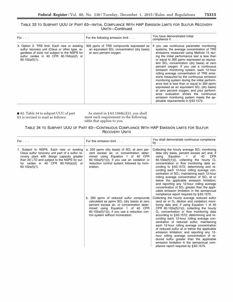
75315 Federal Register / Vol. 80, No. 230 / Tuesday, December 1, 2015 / Rules and Regulations
TABLE 33 TO SUBPART UUU OF PART 63—INITIAL COMPLIANCE WITH HAP EMISSION LIMITS FOR SULFUR RECOVERY UNITS—Continued
For . . . For the following emission limit . . . You have demonstrated initial compliance if . . .
3. Option 2: TRS limit. Each new or existing sulfur recovery unit (Claus or other type, re-gardless of size) not subject to the NSPS for sulfur oxides in 40 CFR 60.104(a)(2) or 60.102a(f)(1).
300 ppmv of TRS compounds expressed as an equivalent SO2 concentration (dry basis) at zero percent oxygen.
If you use continuous parameter monitoring systems, the average concentration of TRS emissions measured using Method 15 dur-ing the initial performance test is less than or equal to 300 ppmv expressed as equiva-lent SO2 concentration (dry basis) at zero percent oxygen. If you use a continuous emission monitoring system, each 12-hour rolling average concentration of TRS emis-sions measured by the continuous emission monitoring system during the initial perform-ance test is less than or equal to 300 ppmv expressed as an equivalent SO2 (dry basis) at zero percent oxygen; and your perform-ance evaluation shows the continuous emission monitoring system meets the ap-plicable requirements in § 63.1572.
■ 82. Table 34 to subpart UUU of part 63 is revised to read as follows:
As stated in § 63.1568(c)(1), you shall meet each requirement in the following table that applies to you.
TABLE 34 TO SUBPART UUU OF PART 63—CONTINUOUS COMPLIANCE WITH HAP EMISSION LIMITS FOR SULFUR RECOVERY UNITS
For . . . For this emission limit . . . You shall demonstrate continuous compliance by . . .
1. Subject to NSPS. Each new or existing Claus sulfur recovery unit part of a sulfur re-covery plant with design capacity greater than 20 LTD and subject to the NSPS for sul-fur oxides in 40 CFR 60.104(a)(2) or 60.102a(f)(1).
a. 250 ppmv (dry basis) of SO2 at zero per-cent excess air, or concentration deter-mined using Equation 1 of 40 CFR 60.102a(f)(1)(i), if you use an oxidation or reduction control system followed by incin-eration.
Collecting the hourly average SO2 monitoring data (dry basis, percent excess air) and, if using Equation 1 of 40 CFR 60.102a(f)(1)(i), collecting the hourly O2 concentration or flow monitoring data ac-cording to § 63.1572; determining and re-cording each 12-hour rolling average con-centration of SO2; maintaining each 12-hour rolling average concentration of SO2 at or below the applicable emission limitation; and reporting any 12-hour rolling average concentration of SO2 greater than the appli-cable emission limitation in the semiannual compliance report required by § 63.1575.
b. 300 ppmv of reduced sulfur compounds calculated as ppmv SO2 (dry basis) at zero percent excess air, or concentration deter-mined using Equation 1 of 40 CFR 60.102a(f)(1)(i), if you use a reduction con-trol system without incineration.
Collecting the hourly average reduced sulfur (and air or O2 dilution and oxidation) moni-toring data and, if using Equation 1 of 40 CFR 60.102a(f)(1)(i), collecting the hourly O2 concentration or flow monitoring data according to § 63.1572; determining and re-cording each 12-hour rolling average con-centration of reduced sulfur; maintaining each 12-hour rolling average concentration of reduced sulfur at or below the applicable emission limitation; and reporting any 12- hour rolling average concentration of re-duced sulfur greater than the applicable emission limitation in the semiannual com-pliance report required by § 63.1575.
VerDate Sep<11>2014 23:11 Nov 30, 2015 Jkt 238001 PO 00000 Frm 00139 Fmt 4701 Sfmt 4700 E:\FR\FM\01DER2.SGM 01DER2tkel
ley
on D
SK
3SP
TV
N1P
RO
D w
ith R
ULE
S2
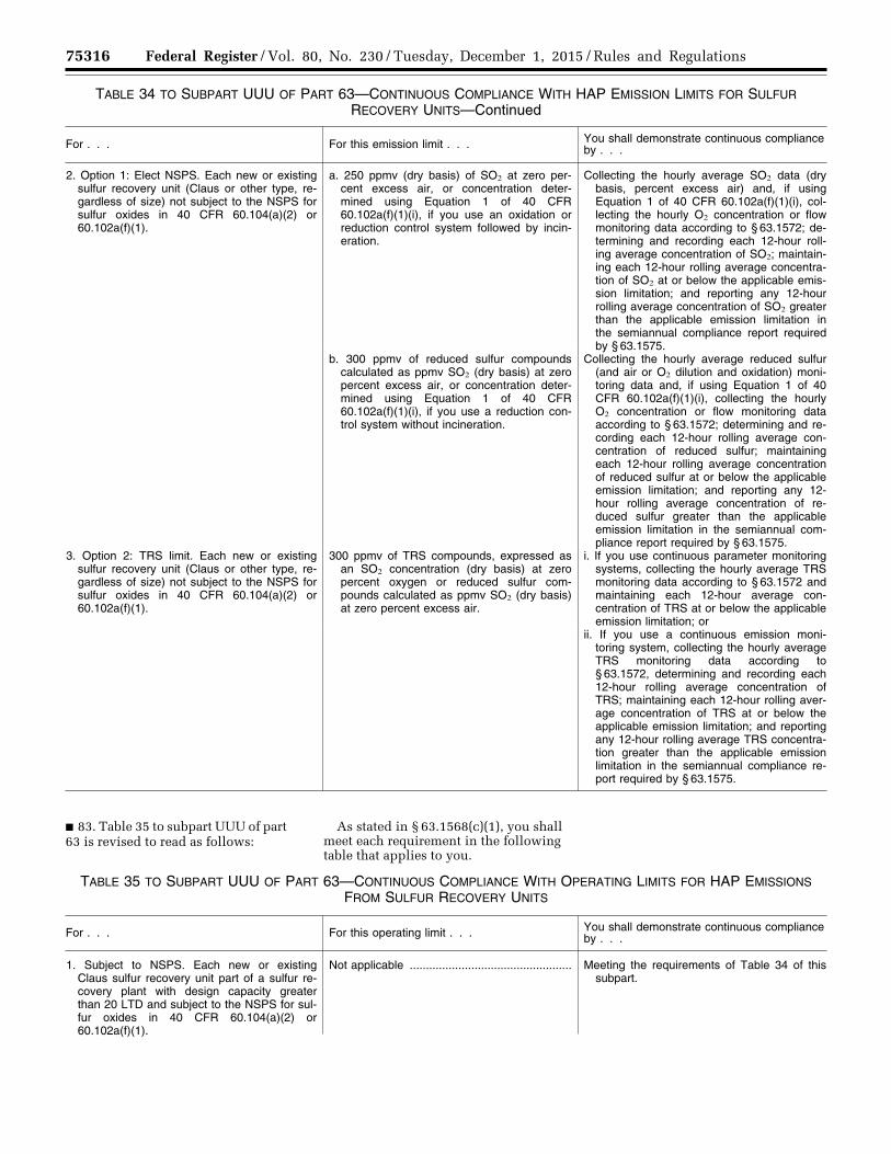
75316 Federal Register / Vol. 80, No. 230 / Tuesday, December 1, 2015 / Rules and Regulations
TABLE 34 TO SUBPART UUU OF PART 63—CONTINUOUS COMPLIANCE WITH HAP EMISSION LIMITS FOR SULFUR RECOVERY UNITS—Continued
For . . . For this emission limit . . . You shall demonstrate continuous compliance by . . .
2. Option 1: Elect NSPS. Each new or existing sulfur recovery unit (Claus or other type, re-gardless of size) not subject to the NSPS for sulfur oxides in 40 CFR 60.104(a)(2) or 60.102a(f)(1).
a. 250 ppmv (dry basis) of SO2 at zero per-cent excess air, or concentration deter-mined using Equation 1 of 40 CFR 60.102a(f)(1)(i), if you use an oxidation or reduction control system followed by incin-eration.
Collecting the hourly average SO2 data (dry basis, percent excess air) and, if using Equation 1 of 40 CFR 60.102a(f)(1)(i), col-lecting the hourly O2 concentration or flow monitoring data according to § 63.1572; de-termining and recording each 12-hour roll-ing average concentration of SO2; maintain-ing each 12-hour rolling average concentra-tion of SO2 at or below the applicable emis-sion limitation; and reporting any 12-hour rolling average concentration of SO2 greater than the applicable emission limitation in the semiannual compliance report required by § 63.1575.
b. 300 ppmv of reduced sulfur compounds calculated as ppmv SO2 (dry basis) at zero percent excess air, or concentration deter-mined using Equation 1 of 40 CFR 60.102a(f)(1)(i), if you use a reduction con-trol system without incineration.
Collecting the hourly average reduced sulfur (and air or O2 dilution and oxidation) moni-toring data and, if using Equation 1 of 40 CFR 60.102a(f)(1)(i), collecting the hourly O2 concentration or flow monitoring data according to § 63.1572; determining and re-cording each 12-hour rolling average con-centration of reduced sulfur; maintaining each 12-hour rolling average concentration of reduced sulfur at or below the applicable emission limitation; and reporting any 12- hour rolling average concentration of re-duced sulfur greater than the applicable emission limitation in the semiannual com-pliance report required by § 63.1575.
3. Option 2: TRS limit. Each new or existing sulfur recovery unit (Claus or other type, re-gardless of size) not subject to the NSPS for sulfur oxides in 40 CFR 60.104(a)(2) or 60.102a(f)(1).
300 ppmv of TRS compounds, expressed as an SO2 concentration (dry basis) at zero percent oxygen or reduced sulfur com-pounds calculated as ppmv SO2 (dry basis) at zero percent excess air.
i. If you use continuous parameter monitoring systems, collecting the hourly average TRS monitoring data according to § 63.1572 and maintaining each 12-hour average con-centration of TRS at or below the applicable emission limitation; or
ii. If you use a continuous emission moni-toring system, collecting the hourly average TRS monitoring data according to § 63.1572, determining and recording each 12-hour rolling average concentration of TRS; maintaining each 12-hour rolling aver-age concentration of TRS at or below the applicable emission limitation; and reporting any 12-hour rolling average TRS concentra-tion greater than the applicable emission limitation in the semiannual compliance re-port required by § 63.1575.
■ 83. Table 35 to subpart UUU of part 63 is revised to read as follows:
As stated in § 63.1568(c)(1), you shall meet each requirement in the following table that applies to you.
TABLE 35 TO SUBPART UUU OF PART 63—CONTINUOUS COMPLIANCE WITH OPERATING LIMITS FOR HAP EMISSIONS FROM SULFUR RECOVERY UNITS
For . . . For this operating limit . . . You shall demonstrate continuous compliance by . . .
1. Subject to NSPS. Each new or existing Claus sulfur recovery unit part of a sulfur re-covery plant with design capacity greater than 20 LTD and subject to the NSPS for sul-fur oxides in 40 CFR 60.104(a)(2) or 60.102a(f)(1).
Not applicable .................................................. Meeting the requirements of Table 34 of this subpart.
VerDate Sep<11>2014 23:11 Nov 30, 2015 Jkt 238001 PO 00000 Frm 00140 Fmt 4701 Sfmt 4700 E:\FR\FM\01DER2.SGM 01DER2tkel
ley
on D
SK
3SP
TV
N1P
RO
D w
ith R
ULE
S2

75317 Federal Register / Vol. 80, No. 230 / Tuesday, December 1, 2015 / Rules and Regulations
TABLE 35 TO SUBPART UUU OF PART 63—CONTINUOUS COMPLIANCE WITH OPERATING LIMITS FOR HAP EMISSIONS FROM SULFUR RECOVERY UNITS—Continued
For . . . For this operating limit . . . You shall demonstrate continuous compliance by . . .
2. Option 1: Elect NSPS. Each new or existing sulfur recovery unit (Claus or other type, re-gardless of size) not subject to the NSPS for sulfur oxides in 40 CFR 60.104(a)(2) or 60.102a(f)(1).
Not applicable .................................................. Meeting the requirements of Table 34 of this subpart.
3. Option 2: TRS limit. Each new or existing sulfur recovery unit (Claus or other type, re-gardless of size) not subject to the NSPS for sulfur oxides in 40 CFR 60.104(a)(2) or 60.102a(f)(1).
a. Maintain the daily average combustion zone temperature above the level estab-lished during the performance test.
Collecting the hourly and daily average tem-perature monitoring data according to § 63.1572; and maintaining the daily aver-age combustion zone temperature at or above the limit established during the per-formance test
b. The daily average oxygen concentration in the vent stream (percent, dry basis) must not fall below the level established during the performance test..
Collecting the hourly and daily average O2 monitoring data according to § 63.1572; and maintaining the average O2 concentration above the level established during the per-formance test.
4. Startup or shutdown option 1: Electing to comply with § 63.1568(a)(4)(ii). Each new or existing sulfur recovery unit (Claus or other type, regardless of size) during periods of startup or shutdown.
Using a flare meeting the requirements in § 63.11(b) or § 63.670.
On and after January 30, 2019, complying with the applicable requirements of § 63.670. Prior to January 30, 2019, com-plying with the applicable requirements of either § 63.11(b) or § 63.670.
5. Startup or shutdown option 2: Electing to comply with § 63.1568(a)(4)(iii). Each new or existing sulfur recovery unit (Claus or other type, regardless of size) during periods of startup or shutdown.
a. Minimum hourly average temperature of 1,200 degrees Fahrenheit.
Collecting continuous (at least once every 15 minutes) and hourly average temperature monitoring data according to § 63.1572; and maintaining the daily average firebox tem-perature at or above 1,200 degrees Fahr-enheit.
b. Minimum hourly average outlet oxygen concentration of 2 volume percent (dry basis).
Collecting continuous (at least once every 15 minutes) and hourly average O2 monitoring data according to § 63.1572; and maintain-ing the average O2 concentration at or above 2 volume percent (dry basis).
■ 84. Table 40 to subpart UUU of part 63 is revised to read as follows:
As stated in § 63.1572(a)(1) and (b)(1), you shall meet each requirement in the following table that applies to you.
TABLE 40 TO SUBPART UUU OF PART 63—REQUIREMENTS FOR INSTALLATION, OPERATION, AND MAINTENANCE OF CONTINUOUS OPACITY MONITORING SYSTEMS AND CONTINUOUS EMISSION MONITORING SYSTEMS
This type of continuous opacity or emission monitoring system . . . Must meet these requirements . . .
1. Continuous opacity monitoring system ................................................ Performance specification 1 (40 CFR part 60, appendix B). 2. PM CEMS; this monitor must include an O2 monitor for correcting
the data for excess air.The requirements in 40 CFR 60.105a(d).
3. CO continuous emission monitoring system ........................................ Performance specification 4 (40 CFR part 60, appendix B); span value of 1,000 ppm; and procedure 1 (40 CFR part 60, appendix F) except relative accuracy test audits are required annually instead of quar-terly.
4. CO continuous emission monitoring system used to demonstrate emissions average under 50 ppm (dry basis).
Performance specification 4 (40 CFR part 60, appendix B); and span value of 100 ppm.
5. SO2 continuous emission monitoring system for sulfur recovery unit with oxidation control system or reduction control system; this mon-itor must include an O2 monitor for correcting the data for excess air.
Performance specification 2 (40 CFR part 60, appendix B); span value of 500 ppm SO2, or if using Equation 1 of 40 CFR 60.102a(f)(1)(i), span value of two times the limit at the highest O2 concentration; use Methods 6 or 6C (40 CFR part 60, appendix A–4) for certifying the SO2 monitor and Methods 3A or 3B (40 CFR part 60, appendix A–2) for certifying the O2 monitor; and procedure 1 (40 CFR part 60, ap-pendix F) except relative accuracy test audits are required annually instead of quarterly.
VerDate Sep<11>2014 23:11 Nov 30, 2015 Jkt 238001 PO 00000 Frm 00141 Fmt 4701 Sfmt 4700 E:\FR\FM\01DER2.SGM 01DER2tkel
ley
on D
SK
3SP
TV
N1P
RO
D w
ith R
ULE
S2
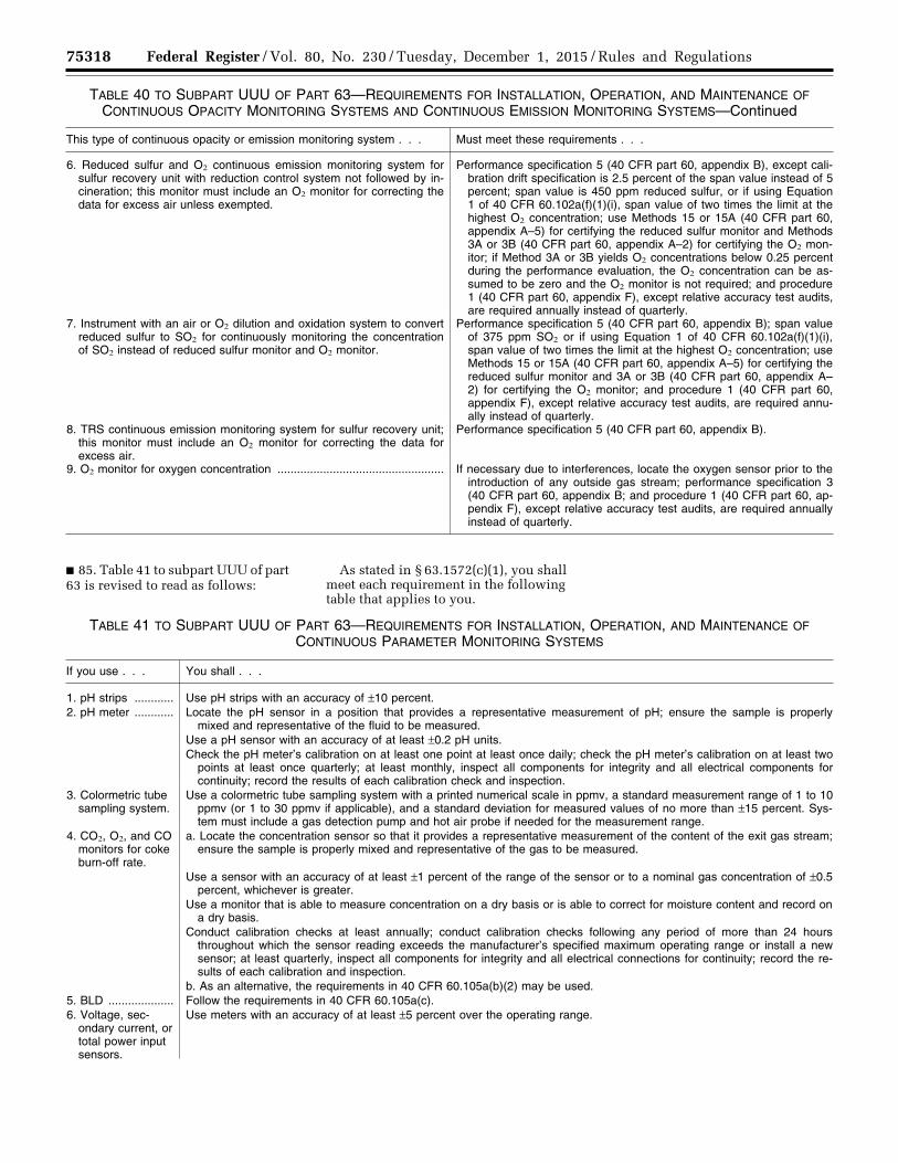
75318 Federal Register / Vol. 80, No. 230 / Tuesday, December 1, 2015 / Rules and Regulations
TABLE 40 TO SUBPART UUU OF PART 63—REQUIREMENTS FOR INSTALLATION, OPERATION, AND MAINTENANCE OF CONTINUOUS OPACITY MONITORING SYSTEMS AND CONTINUOUS EMISSION MONITORING SYSTEMS—Continued
This type of continuous opacity or emission monitoring system . . . Must meet these requirements . . .
6. Reduced sulfur and O2 continuous emission monitoring system for sulfur recovery unit with reduction control system not followed by in-cineration; this monitor must include an O2 monitor for correcting the data for excess air unless exempted.
Performance specification 5 (40 CFR part 60, appendix B), except cali-bration drift specification is 2.5 percent of the span value instead of 5 percent; span value is 450 ppm reduced sulfur, or if using Equation 1 of 40 CFR 60.102a(f)(1)(i), span value of two times the limit at the highest O2 concentration; use Methods 15 or 15A (40 CFR part 60, appendix A–5) for certifying the reduced sulfur monitor and Methods 3A or 3B (40 CFR part 60, appendix A–2) for certifying the O2 mon-itor; if Method 3A or 3B yields O2 concentrations below 0.25 percent during the performance evaluation, the O2 concentration can be as-sumed to be zero and the O2 monitor is not required; and procedure 1 (40 CFR part 60, appendix F), except relative accuracy test audits, are required annually instead of quarterly.
7. Instrument with an air or O2 dilution and oxidation system to convert reduced sulfur to SO2 for continuously monitoring the concentration of SO2 instead of reduced sulfur monitor and O2 monitor.
Performance specification 5 (40 CFR part 60, appendix B); span value of 375 ppm SO2 or if using Equation 1 of 40 CFR 60.102a(f)(1)(i), span value of two times the limit at the highest O2 concentration; use Methods 15 or 15A (40 CFR part 60, appendix A–5) for certifying the reduced sulfur monitor and 3A or 3B (40 CFR part 60, appendix A– 2) for certifying the O2 monitor; and procedure 1 (40 CFR part 60, appendix F), except relative accuracy test audits, are required annu-ally instead of quarterly.
8. TRS continuous emission monitoring system for sulfur recovery unit; this monitor must include an O2 monitor for correcting the data for excess air.
Performance specification 5 (40 CFR part 60, appendix B).
9. O2 monitor for oxygen concentration ................................................... If necessary due to interferences, locate the oxygen sensor prior to the introduction of any outside gas stream; performance specification 3 (40 CFR part 60, appendix B; and procedure 1 (40 CFR part 60, ap-pendix F), except relative accuracy test audits, are required annually instead of quarterly.
■ 85. Table 41 to subpart UUU of part 63 is revised to read as follows:
As stated in § 63.1572(c)(1), you shall meet each requirement in the following table that applies to you.
TABLE 41 TO SUBPART UUU OF PART 63—REQUIREMENTS FOR INSTALLATION, OPERATION, AND MAINTENANCE OF CONTINUOUS PARAMETER MONITORING SYSTEMS
If you use . . . You shall . . .
1. pH strips ............ Use pH strips with an accuracy of ±10 percent. 2. pH meter ............ Locate the pH sensor in a position that provides a representative measurement of pH; ensure the sample is properly
mixed and representative of the fluid to be measured. Use a pH sensor with an accuracy of at least ±0.2 pH units. Check the pH meter’s calibration on at least one point at least once daily; check the pH meter’s calibration on at least two
points at least once quarterly; at least monthly, inspect all components for integrity and all electrical components for continuity; record the results of each calibration check and inspection.
3. Colormetric tube sampling system.
Use a colormetric tube sampling system with a printed numerical scale in ppmv, a standard measurement range of 1 to 10 ppmv (or 1 to 30 ppmv if applicable), and a standard deviation for measured values of no more than ±15 percent. Sys-tem must include a gas detection pump and hot air probe if needed for the measurement range.
4. CO2, O2, and CO monitors for coke burn-off rate.
a. Locate the concentration sensor so that it provides a representative measurement of the content of the exit gas stream; ensure the sample is properly mixed and representative of the gas to be measured.
Use a sensor with an accuracy of at least ±1 percent of the range of the sensor or to a nominal gas concentration of ±0.5 percent, whichever is greater.
Use a monitor that is able to measure concentration on a dry basis or is able to correct for moisture content and record on a dry basis.
Conduct calibration checks at least annually; conduct calibration checks following any period of more than 24 hours throughout which the sensor reading exceeds the manufacturer’s specified maximum operating range or install a new sensor; at least quarterly, inspect all components for integrity and all electrical connections for continuity; record the re-sults of each calibration and inspection.
b. As an alternative, the requirements in 40 CFR 60.105a(b)(2) may be used. 5. BLD .................... Follow the requirements in 40 CFR 60.105a(c). 6. Voltage, sec-
ondary current, or total power input sensors.
Use meters with an accuracy of at least ±5 percent over the operating range.
VerDate Sep<11>2014 23:11 Nov 30, 2015 Jkt 238001 PO 00000 Frm 00142 Fmt 4701 Sfmt 4700 E:\FR\FM\01DER2.SGM 01DER2tkel
ley
on D
SK
3SP
TV
N1P
RO
D w
ith R
ULE
S2
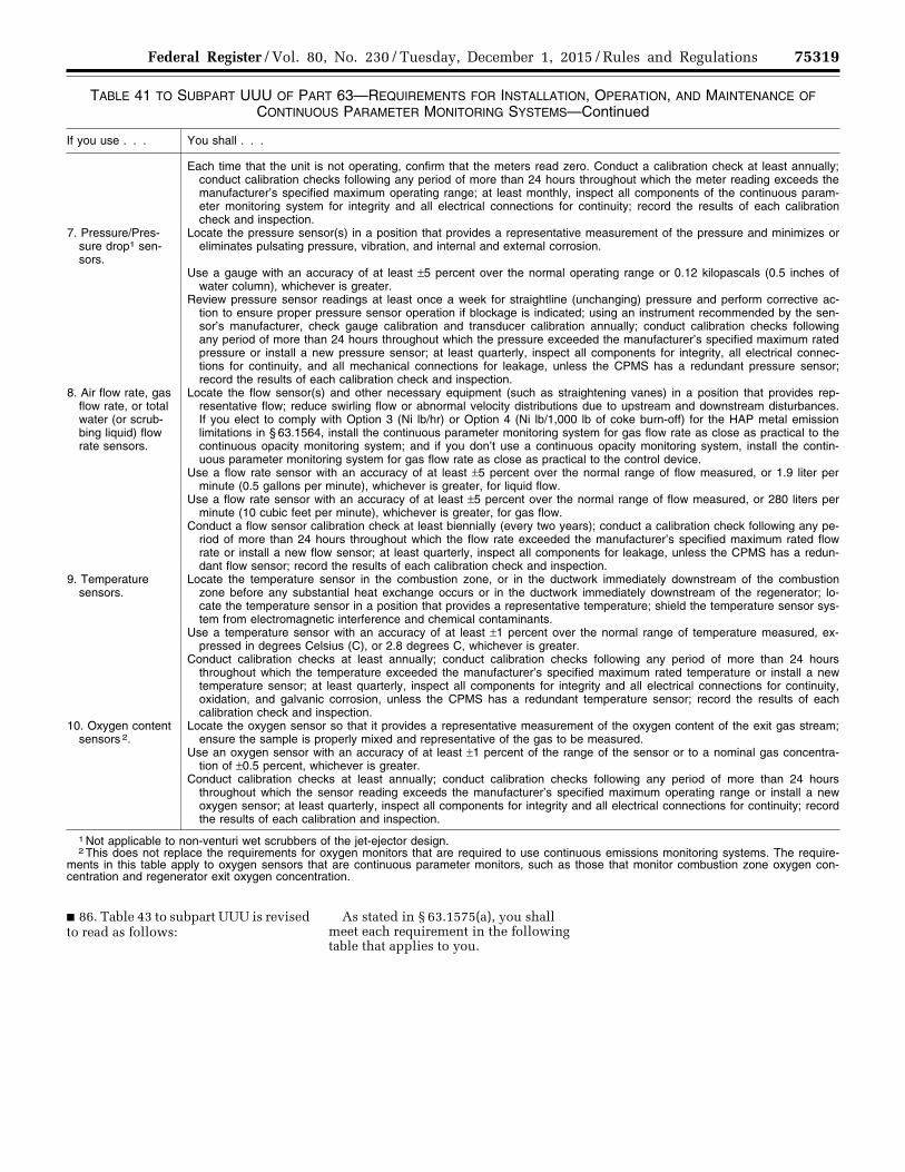
75319 Federal Register / Vol. 80, No. 230 / Tuesday, December 1, 2015 / Rules and Regulations
TABLE 41 TO SUBPART UUU OF PART 63—REQUIREMENTS FOR INSTALLATION, OPERATION, AND MAINTENANCE OF CONTINUOUS PARAMETER MONITORING SYSTEMS—Continued
If you use . . . You shall . . .
Each time that the unit is not operating, confirm that the meters read zero. Conduct a calibration check at least annually; conduct calibration checks following any period of more than 24 hours throughout which the meter reading exceeds the manufacturer’s specified maximum operating range; at least monthly, inspect all components of the continuous param-eter monitoring system for integrity and all electrical connections for continuity; record the results of each calibration check and inspection.
7. Pressure/Pres-sure drop1 sen-sors.
Locate the pressure sensor(s) in a position that provides a representative measurement of the pressure and minimizes or eliminates pulsating pressure, vibration, and internal and external corrosion.
Use a gauge with an accuracy of at least ±5 percent over the normal operating range or 0.12 kilopascals (0.5 inches of water column), whichever is greater.
Review pressure sensor readings at least once a week for straightline (unchanging) pressure and perform corrective ac-tion to ensure proper pressure sensor operation if blockage is indicated; using an instrument recommended by the sen-sor’s manufacturer, check gauge calibration and transducer calibration annually; conduct calibration checks following any period of more than 24 hours throughout which the pressure exceeded the manufacturer’s specified maximum rated pressure or install a new pressure sensor; at least quarterly, inspect all components for integrity, all electrical connec-tions for continuity, and all mechanical connections for leakage, unless the CPMS has a redundant pressure sensor; record the results of each calibration check and inspection.
8. Air flow rate, gas flow rate, or total water (or scrub-bing liquid) flow rate sensors.
Locate the flow sensor(s) and other necessary equipment (such as straightening vanes) in a position that provides rep-resentative flow; reduce swirling flow or abnormal velocity distributions due to upstream and downstream disturbances. If you elect to comply with Option 3 (Ni lb/hr) or Option 4 (Ni lb/1,000 lb of coke burn-off) for the HAP metal emission limitations in § 63.1564, install the continuous parameter monitoring system for gas flow rate as close as practical to the continuous opacity monitoring system; and if you don’t use a continuous opacity monitoring system, install the contin-uous parameter monitoring system for gas flow rate as close as practical to the control device.
Use a flow rate sensor with an accuracy of at least ±5 percent over the normal range of flow measured, or 1.9 liter per minute (0.5 gallons per minute), whichever is greater, for liquid flow.
Use a flow rate sensor with an accuracy of at least ±5 percent over the normal range of flow measured, or 280 liters per minute (10 cubic feet per minute), whichever is greater, for gas flow.
Conduct a flow sensor calibration check at least biennially (every two years); conduct a calibration check following any pe-riod of more than 24 hours throughout which the flow rate exceeded the manufacturer’s specified maximum rated flow rate or install a new flow sensor; at least quarterly, inspect all components for leakage, unless the CPMS has a redun-dant flow sensor; record the results of each calibration check and inspection.
9. Temperature sensors.
Locate the temperature sensor in the combustion zone, or in the ductwork immediately downstream of the combustion zone before any substantial heat exchange occurs or in the ductwork immediately downstream of the regenerator; lo-cate the temperature sensor in a position that provides a representative temperature; shield the temperature sensor sys-tem from electromagnetic interference and chemical contaminants.
Use a temperature sensor with an accuracy of at least ±1 percent over the normal range of temperature measured, ex-pressed in degrees Celsius (C), or 2.8 degrees C, whichever is greater.
Conduct calibration checks at least annually; conduct calibration checks following any period of more than 24 hours throughout which the temperature exceeded the manufacturer’s specified maximum rated temperature or install a new temperature sensor; at least quarterly, inspect all components for integrity and all electrical connections for continuity, oxidation, and galvanic corrosion, unless the CPMS has a redundant temperature sensor; record the results of each calibration check and inspection.
10. Oxygen content sensors 2.
Locate the oxygen sensor so that it provides a representative measurement of the oxygen content of the exit gas stream; ensure the sample is properly mixed and representative of the gas to be measured.
Use an oxygen sensor with an accuracy of at least ±1 percent of the range of the sensor or to a nominal gas concentra-tion of ±0.5 percent, whichever is greater.
Conduct calibration checks at least annually; conduct calibration checks following any period of more than 24 hours throughout which the sensor reading exceeds the manufacturer’s specified maximum operating range or install a new oxygen sensor; at least quarterly, inspect all components for integrity and all electrical connections for continuity; record the results of each calibration and inspection.
1 Not applicable to non-venturi wet scrubbers of the jet-ejector design. 2 This does not replace the requirements for oxygen monitors that are required to use continuous emissions monitoring systems. The require-
ments in this table apply to oxygen sensors that are continuous parameter monitors, such as those that monitor combustion zone oxygen con-centration and regenerator exit oxygen concentration.
■ 86. Table 43 to subpart UUU is revised to read as follows:
As stated in § 63.1575(a), you shall meet each requirement in the following table that applies to you.
VerDate Sep<11>2014 23:11 Nov 30, 2015 Jkt 238001 PO 00000 Frm 00143 Fmt 4701 Sfmt 4700 E:\FR\FM\01DER2.SGM 01DER2tkel
ley
on D
SK
3SP
TV
N1P
RO
D w
ith R
ULE
S2
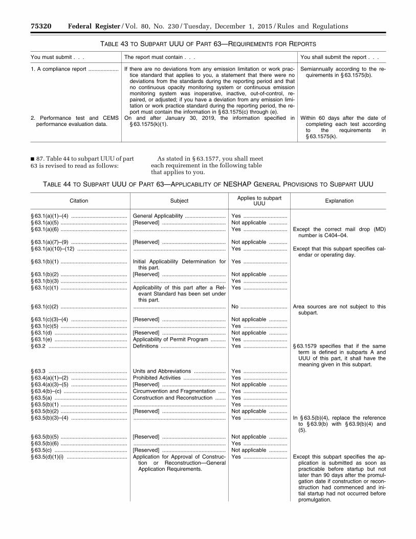
75320 Federal Register / Vol. 80, No. 230 / Tuesday, December 1, 2015 / Rules and Regulations
TABLE 43 TO SUBPART UUU OF PART 63—REQUIREMENTS FOR REPORTS
You must submit . . . The report must contain . . . You shall submit the report . . .
1. A compliance report .................... If there are no deviations from any emission limitation or work prac-tice standard that applies to you, a statement that there were no deviations from the standards during the reporting period and that no continuous opacity monitoring system or continuous emission monitoring system was inoperative, inactive, out-of-control, re-paired, or adjusted; if you have a deviation from any emission limi-tation or work practice standard during the reporting period, the re-port must contain the information in § 63.1575(c) through (e).
Semiannually according to the re-quirements in § 63.1575(b).
2. Performance test and CEMS performance evaluation data.
On and after January 30, 2019, the information specified in § 63.1575(k)(1).
Within 60 days after the date of completing each test according to the requirements in § 63.1575(k).
■ 87. Table 44 to subpart UUU of part 63 is revised to read as follows:
As stated in § 63.1577, you shall meet each requirement in the following table that applies to you.
TABLE 44 TO SUBPART UUU OF PART 63—APPLICABILITY OF NESHAP GENERAL PROVISIONS TO SUBPART UUU
Citation Subject Applies to subpart UUU Explanation
§ 63.1(a)(1)–(4) ..................................... General Applicability ........................... Yes .............................§ 63.1(a)(5) ............................................ [Reserved] .......................................... Not applicable ............§ 63.1(a)(6) ............................................ ............................................................. Yes ............................. Except the correct mail drop (MD)
number is C404–04. § 63.1(a)(7)–(9) ..................................... [Reserved] .......................................... Not applicable ............§ 63.1(a)(10)–(12) ................................. ............................................................. Yes ............................. Except that this subpart specifies cal-
endar or operating day. § 63.1(b)(1) ............................................ Initial Applicability Determination for
this part.Yes .............................
§ 63.1(b)(2) ............................................ [Reserved] .......................................... Not applicable ............§ 63.1(b)(3) ............................................ ............................................................. Yes .............................§ 63.1(c)(1) ............................................ Applicability of this part after a Rel-
evant Standard has been set under this part.
Yes .............................
§ 63.1(c)(2) ............................................ ............................................................. No ............................... Area sources are not subject to this subpart.
§ 63.1(c)(3)–(4) ..................................... [Reserved] .......................................... Not applicable ............§ 63.1(c)(5) ............................................ ............................................................. Yes .............................§ 63.1(d) ................................................ [Reserved] .......................................... Not applicable ............§ 63.1(e) ................................................ Applicability of Permit Program .......... Yes .............................§ 63.2 .................................................... Definitions ........................................... Yes ............................. § 63.1579 specifies that if the same
term is defined in subparts A and UUU of this part, it shall have the meaning given in this subpart.
§ 63.3 .................................................... Units and Abbreviations ..................... Yes .............................§ 63.4(a)(1)–(2) ..................................... Prohibited Activities ............................ Yes .............................§ 63.4(a)(3)–(5) ..................................... [Reserved] .......................................... Not applicable ............§ 63.4(b)–(c) .......................................... Circumvention and Fragmentation ..... Yes .............................§ 63.5(a) ................................................ Construction and Reconstruction ....... Yes .............................§ 63.5(b)(1) ............................................ ............................................................. Yes .............................§ 63.5(b)(2) ............................................ [Reserved] .......................................... Not applicable ............§ 63.5(b)(3)–(4) ..................................... ............................................................. Yes ............................. In § 63.5(b)(4), replace the reference
to § 63.9(b) with § 63.9(b)(4) and (5).
§ 63.5(b)(5) ............................................ [Reserved] .......................................... Not applicable ............§ 63.5(b)(6) ............................................ ............................................................. Yes .............................§ 63.5(c) ................................................ [Reserved] .......................................... Not applicable ............§ 63.5(d)(1)(i) ........................................ Application for Approval of Construc-
tion or Reconstruction—General Application Requirements.
Yes ............................. Except this subpart specifies the ap-plication is submitted as soon as practicable before startup but not later than 90 days after the promul-gation date if construction or recon-struction had commenced and ini-tial startup had not occurred before promulgation.
VerDate Sep<11>2014 23:11 Nov 30, 2015 Jkt 238001 PO 00000 Frm 00144 Fmt 4701 Sfmt 4700 E:\FR\FM\01DER2.SGM 01DER2tkel
ley
on D
SK
3SP
TV
N1P
RO
D w
ith R
ULE
S2
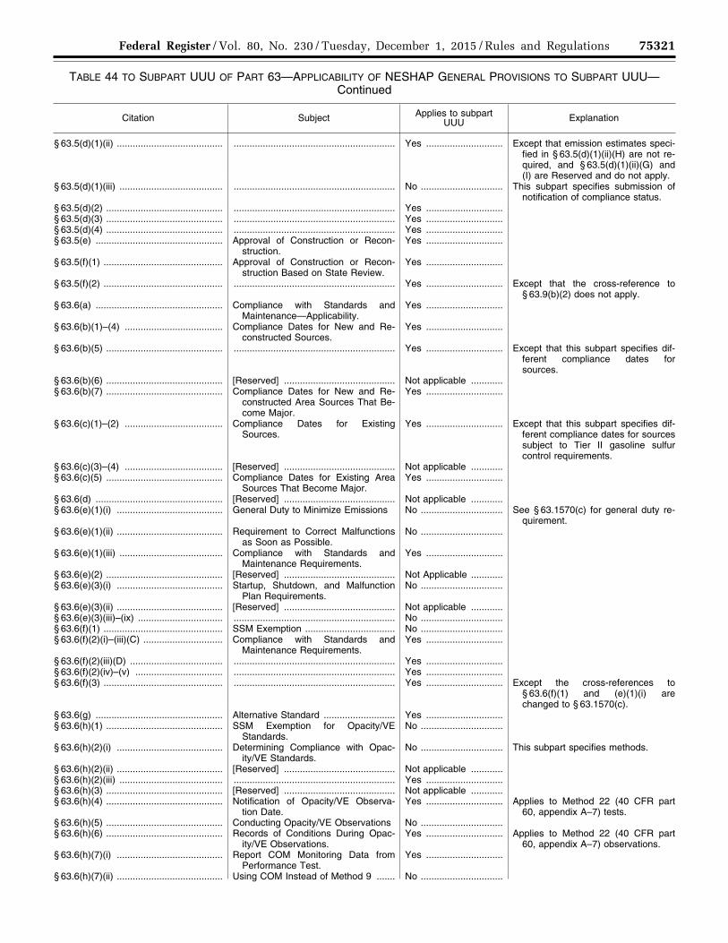
75321 Federal Register / Vol. 80, No. 230 / Tuesday, December 1, 2015 / Rules and Regulations
TABLE 44 TO SUBPART UUU OF PART 63—APPLICABILITY OF NESHAP GENERAL PROVISIONS TO SUBPART UUU— Continued
Citation Subject Applies to subpart UUU Explanation
§ 63.5(d)(1)(ii) ........................................ ............................................................. Yes ............................. Except that emission estimates speci-fied in § 63.5(d)(1)(ii)(H) are not re-quired, and § 63.5(d)(1)(ii)(G) and (I) are Reserved and do not apply.
§ 63.5(d)(1)(iii) ....................................... ............................................................. No ............................... This subpart specifies submission of notification of compliance status.
§ 63.5(d)(2) ............................................ ............................................................. Yes .............................§ 63.5(d)(3) ............................................ ............................................................. Yes .............................§ 63.5(d)(4) ............................................ ............................................................. Yes .............................§ 63.5(e) ................................................ Approval of Construction or Recon-
struction.Yes .............................
§ 63.5(f)(1) ............................................. Approval of Construction or Recon-struction Based on State Review.
Yes .............................
§ 63.5(f)(2) ............................................. ............................................................. Yes ............................. Except that the cross-reference to § 63.9(b)(2) does not apply.
§ 63.6(a) ................................................ Compliance with Standards and Maintenance—Applicability.
Yes .............................
§ 63.6(b)(1)–(4) ..................................... Compliance Dates for New and Re-constructed Sources.
Yes .............................
§ 63.6(b)(5) ............................................ ............................................................. Yes ............................. Except that this subpart specifies dif-ferent compliance dates for sources.
§ 63.6(b)(6) ............................................ [Reserved] .......................................... Not applicable ............§ 63.6(b)(7) ............................................ Compliance Dates for New and Re-
constructed Area Sources That Be-come Major.
Yes .............................
§ 63.6(c)(1)–(2) ..................................... Compliance Dates for Existing Sources.
Yes ............................. Except that this subpart specifies dif-ferent compliance dates for sources subject to Tier II gasoline sulfur control requirements.
§ 63.6(c)(3)–(4) ..................................... [Reserved] .......................................... Not applicable ............§ 63.6(c)(5) ............................................ Compliance Dates for Existing Area
Sources That Become Major.Yes .............................
§ 63.6(d) ................................................ [Reserved] .......................................... Not applicable ............§ 63.6(e)(1)(i) ........................................ General Duty to Minimize Emissions No ............................... See § 63.1570(c) for general duty re-
quirement. § 63.6(e)(1)(ii) ........................................ Requirement to Correct Malfunctions
as Soon as Possible.No ...............................
§ 63.6(e)(1)(iii) ....................................... Compliance with Standards and Maintenance Requirements.
Yes .............................
§ 63.6(e)(2) ............................................ [Reserved] .......................................... Not Applicable ............§ 63.6(e)(3)(i) ........................................ Startup, Shutdown, and Malfunction
Plan Requirements.No ...............................
§ 63.6(e)(3)(ii) ........................................ [Reserved] .......................................... Not applicable ............§ 63.6(e)(3)(iii)–(ix) ................................ ............................................................. No ...............................§ 63.6(f)(1) ............................................. SSM Exemption .................................. No ...............................§ 63.6(f)(2)(i)–(iii)(C) .............................. Compliance with Standards and
Maintenance Requirements.Yes .............................
§ 63.6(f)(2)(iii)(D) ................................... ............................................................. Yes .............................§ 63.6(f)(2)(iv)–(v) ................................. ............................................................. Yes .............................§ 63.6(f)(3) ............................................. ............................................................. Yes ............................. Except the cross-references to
§ 63.6(f)(1) and (e)(1)(i) are changed to § 63.1570(c).
§ 63.6(g) ................................................ Alternative Standard ........................... Yes .............................§ 63.6(h)(1) ............................................ SSM Exemption for Opacity/VE
Standards.No ...............................
§ 63.6(h)(2)(i) ........................................ Determining Compliance with Opac-ity/VE Standards.
No ............................... This subpart specifies methods.
§ 63.6(h)(2)(ii) ........................................ [Reserved] .......................................... Not applicable ............§ 63.6(h)(2)(iii) ....................................... ............................................................. Yes .............................§ 63.6(h)(3) ............................................ [Reserved] .......................................... Not applicable ............§ 63.6(h)(4) ............................................ Notification of Opacity/VE Observa-
tion Date.Yes ............................. Applies to Method 22 (40 CFR part
60, appendix A–7) tests. § 63.6(h)(5) ............................................ Conducting Opacity/VE Observations No ...............................§ 63.6(h)(6) ............................................ Records of Conditions During Opac-
ity/VE Observations.Yes ............................. Applies to Method 22 (40 CFR part
60, appendix A–7) observations. § 63.6(h)(7)(i) ........................................ Report COM Monitoring Data from
Performance Test.Yes .............................
§ 63.6(h)(7)(ii) ........................................ Using COM Instead of Method 9 ....... No ...............................
VerDate Sep<11>2014 23:11 Nov 30, 2015 Jkt 238001 PO 00000 Frm 00145 Fmt 4701 Sfmt 4700 E:\FR\FM\01DER2.SGM 01DER2tkel
ley
on D
SK
3SP
TV
N1P
RO
D w
ith R
ULE
S2

75322 Federal Register / Vol. 80, No. 230 / Tuesday, December 1, 2015 / Rules and Regulations
TABLE 44 TO SUBPART UUU OF PART 63—APPLICABILITY OF NESHAP GENERAL PROVISIONS TO SUBPART UUU— Continued
Citation Subject Applies to subpart UUU Explanation
§ 63.6(h)(7)(iii) ....................................... Averaging Time for COM during Per-formance Test.
Yes .............................
§ 63.6(h)(7)(iv) ....................................... COM Requirements ............................ Yes .............................§ 63.6(h)(7)(v) ....................................... COMS Results and Visual Observa-
tions.Yes .............................
§ 63.6(h)(8) ............................................ Determining Compliance with Opac-ity/VE Standards.
Yes .............................
§ 63.6(h)(9) ............................................ Adjusted Opacity Standard ................ Yes .............................§ 63.6(i)(1)–(14) .................................... Extension of Compliance ................... Yes ............................. Extension of compliance under
§ 63.6(i)(4) not applicable to a facil-ity that installs catalytic cracking feed hydrotreating and receives an extended compliance date under § 63.1563(c).
§ 63.6(i)(15) ........................................... [Reserved] .......................................... Not applicable ............§ 63.6(i)(16) ........................................... ............................................................. Yes .............................§ 63.6(j) ................................................. Presidential Compliance Exemption .. Yes .............................§ 63.7(a)(1) ............................................ Performance Test Requirements Ap-
plicability.Yes ............................. Except that this subpart specifies the
applicable test and demonstration procedures.
§ 63.7(a)(2) ............................................ Performance Test Dates .................... Yes ............................. Except test results must be submitted in the Notification of Compliance Status report due 150 days after the compliance date.
§ 63.7(a)(3) ............................................ Section 114 Authority ......................... Yes .............................§ 63.7(a)(4) ............................................ Force Majeure .................................... Yes .............................§ 63.7(b) ................................................ Notifications ........................................ Yes ............................. Except that this subpart specifies no-
tification at least 30 days prior to the scheduled test date rather than 60 days.
§ 63.7(c) ................................................ Quality Assurance Program/Site-Spe-cific Test Plan.
Yes ............................. Except that when this subpart speci-fies to use 40 CFR part 60, appen-dix F, out of control periods are to be defined as specified in part 60, appendix F.
§ 63.7(d) ................................................ Performance Test Facilities ................ Yes .............................§ 63.7(e)(1) ............................................ Performance Testing .......................... No ............................... See § 63.1571(b)(1). § 63.7(e)(2)–(4) ..................................... Conduct of Tests ................................ Yes .............................§ 63.7(f) ................................................. Alternative Test Method ..................... Yes .............................§ 63.7(g) ................................................ Data Analysis, Recordkeeping, Re-
porting.Yes ............................. Except performance test reports must
be submitted with notification of compliance status due 150 days after the compliance date, and § 63.7(g)(2) is reserved and does not apply.
§ 63.7(h) ................................................ Waiver of Tests .................................. Yes .............................§ 63.8(a)(1) ............................................ Monitoring Requirements-Applicability Yes .............................§ 63.8(a)(2) ............................................ Performance Specifications ................ Yes .............................§ 63.8(a)(3) ............................................ [Reserved] .......................................... Not applicable ............§ 63.8(a)(4) ............................................ Monitoring with Flares ........................ Yes ............................. Except that for a flare complying with
§ 63.670, the cross-reference to § 63.11 in this paragraph does not include § 63.11(b).
§ 63.8(b)(1) ............................................ Conduct of Monitoring ........................ Yes .............................§ 63.8(b)(2)–(3) ..................................... Multiple Effluents and Multiple Moni-
toring Systems.Yes ............................. This subpart specifies the required
monitoring locations. § 63.8(c)(1) ............................................ Monitoring System Operation and
Maintenance.Yes .............................
§ 63.8(c)(1)(i) ......................................... General Duty to Minimize Emissions and CMS Operation.
No ............................... See § 63.1570(c).
§ 63.8(c)(1)(ii) ........................................ Keep Necessary Parts for CMS ......... Yes .............................§ 63.8(c)(1)(iii) ....................................... Requirement to Develop SSM Plan
for CMS.No ...............................
VerDate Sep<11>2014 23:11 Nov 30, 2015 Jkt 238001 PO 00000 Frm 00146 Fmt 4701 Sfmt 4700 E:\FR\FM\01DER2.SGM 01DER2tkel
ley
on D
SK
3SP
TV
N1P
RO
D w
ith R
ULE
S2
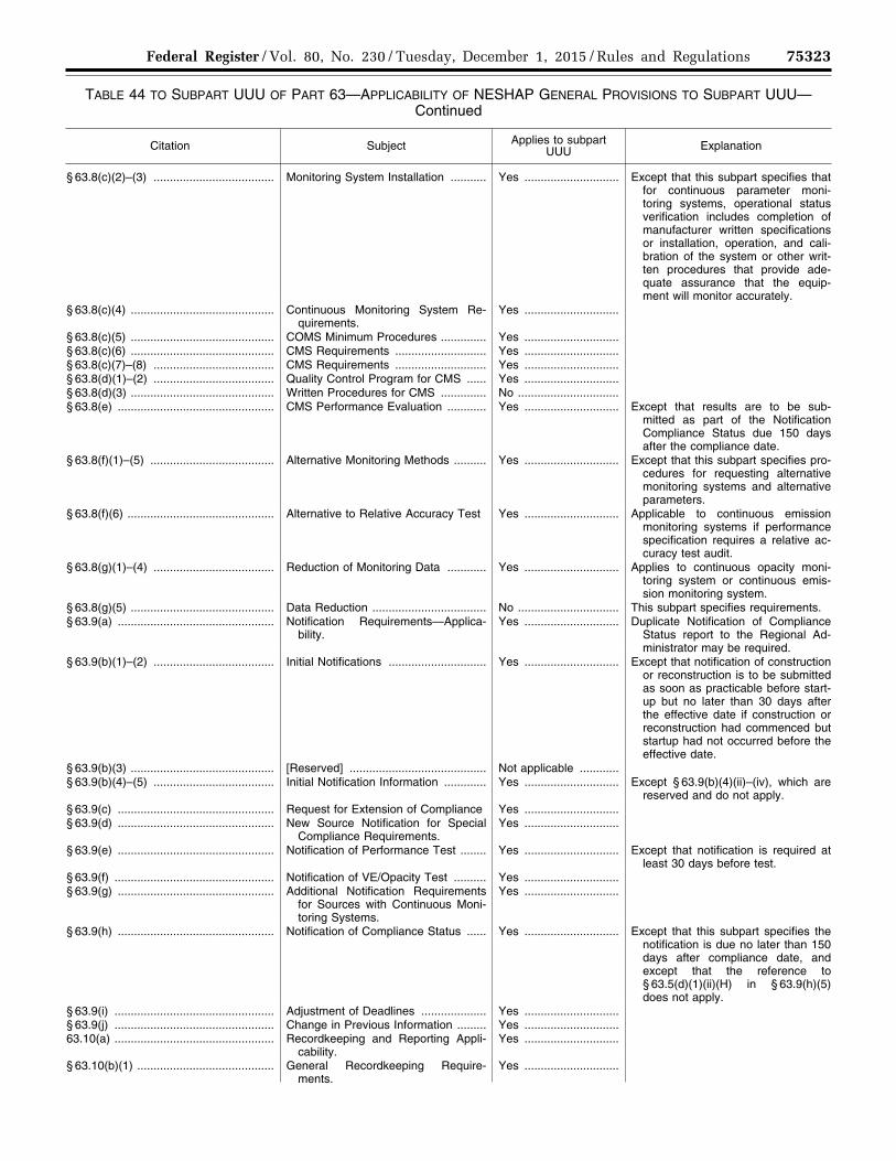
75323 Federal Register / Vol. 80, No. 230 / Tuesday, December 1, 2015 / Rules and Regulations
TABLE 44 TO SUBPART UUU OF PART 63—APPLICABILITY OF NESHAP GENERAL PROVISIONS TO SUBPART UUU— Continued
Citation Subject Applies to subpart UUU Explanation
§ 63.8(c)(2)–(3) ..................................... Monitoring System Installation ........... Yes ............................. Except that this subpart specifies that for continuous parameter moni-toring systems, operational status verification includes completion of manufacturer written specifications or installation, operation, and cali-bration of the system or other writ-ten procedures that provide ade-quate assurance that the equip-ment will monitor accurately.
§ 63.8(c)(4) ............................................ Continuous Monitoring System Re-quirements.
Yes .............................
§ 63.8(c)(5) ............................................ COMS Minimum Procedures .............. Yes .............................§ 63.8(c)(6) ............................................ CMS Requirements ............................ Yes .............................§ 63.8(c)(7)–(8) ..................................... CMS Requirements ............................ Yes .............................§ 63.8(d)(1)–(2) ..................................... Quality Control Program for CMS ...... Yes .............................§ 63.8(d)(3) ............................................ Written Procedures for CMS .............. No ...............................§ 63.8(e) ................................................ CMS Performance Evaluation ............ Yes ............................. Except that results are to be sub-
mitted as part of the Notification Compliance Status due 150 days after the compliance date.
§ 63.8(f)(1)–(5) ...................................... Alternative Monitoring Methods .......... Yes ............................. Except that this subpart specifies pro-cedures for requesting alternative monitoring systems and alternative parameters.
§ 63.8(f)(6) ............................................. Alternative to Relative Accuracy Test Yes ............................. Applicable to continuous emission monitoring systems if performance specification requires a relative ac-curacy test audit.
§ 63.8(g)(1)–(4) ..................................... Reduction of Monitoring Data ............ Yes ............................. Applies to continuous opacity moni-toring system or continuous emis-sion monitoring system.
§ 63.8(g)(5) ............................................ Data Reduction ................................... No ............................... This subpart specifies requirements. § 63.9(a) ................................................ Notification Requirements—Applica-
bility.Yes ............................. Duplicate Notification of Compliance
Status report to the Regional Ad-ministrator may be required.
§ 63.9(b)(1)–(2) ..................................... Initial Notifications .............................. Yes ............................. Except that notification of construction or reconstruction is to be submitted as soon as practicable before start-up but no later than 30 days after the effective date if construction or reconstruction had commenced but startup had not occurred before the effective date.
§ 63.9(b)(3) ............................................ [Reserved] .......................................... Not applicable ............§ 63.9(b)(4)–(5) ..................................... Initial Notification Information ............. Yes ............................. Except § 63.9(b)(4)(ii)–(iv), which are
reserved and do not apply. § 63.9(c) ................................................ Request for Extension of Compliance Yes .............................§ 63.9(d) ................................................ New Source Notification for Special
Compliance Requirements.Yes .............................
§ 63.9(e) ................................................ Notification of Performance Test ........ Yes ............................. Except that notification is required at least 30 days before test.
§ 63.9(f) ................................................. Notification of VE/Opacity Test .......... Yes .............................§ 63.9(g) ................................................ Additional Notification Requirements
for Sources with Continuous Moni-toring Systems.
Yes .............................
§ 63.9(h) ................................................ Notification of Compliance Status ...... Yes ............................. Except that this subpart specifies the notification is due no later than 150 days after compliance date, and except that the reference to § 63.5(d)(1)(ii)(H) in § 63.9(h)(5) does not apply.
§ 63.9(i) ................................................. Adjustment of Deadlines .................... Yes .............................§ 63.9(j) ................................................. Change in Previous Information ......... Yes .............................63.10(a) ................................................. Recordkeeping and Reporting Appli-
cability.Yes .............................
§ 63.10(b)(1) .......................................... General Recordkeeping Require-ments.
Yes .............................
VerDate Sep<11>2014 23:11 Nov 30, 2015 Jkt 238001 PO 00000 Frm 00147 Fmt 4701 Sfmt 4700 E:\FR\FM\01DER2.SGM 01DER2tkel
ley
on D
SK
3SP
TV
N1P
RO
D w
ith R
ULE
S2
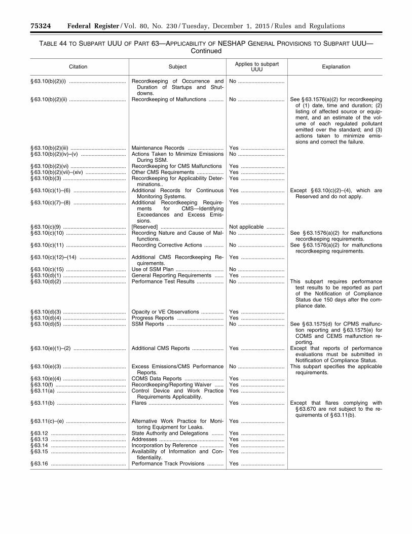
75324 Federal Register / Vol. 80, No. 230 / Tuesday, December 1, 2015 / Rules and Regulations
TABLE 44 TO SUBPART UUU OF PART 63—APPLICABILITY OF NESHAP GENERAL PROVISIONS TO SUBPART UUU— Continued
Citation Subject Applies to subpart UUU Explanation
§ 63.10(b)(2)(i) ...................................... Recordkeeping of Occurrence and Duration of Startups and Shut-downs.
No ...............................
§ 63.10(b)(2)(ii) ...................................... Recordkeeping of Malfunctions .......... No ............................... See § 63.1576(a)(2) for recordkeeping of (1) date, time and duration; (2) listing of affected source or equip-ment, and an estimate of the vol-ume of each regulated pollutant emitted over the standard; and (3) actions taken to minimize emis-sions and correct the failure.
§ 63.10(b)(2)(iii) ..................................... Maintenance Records ........................ Yes .............................§ 63.10(b)(2)(iv)–(v) .............................. Actions Taken to Minimize Emissions
During SSM.No ...............................
§ 63.10(b)(2)(vi) ..................................... Recordkeeping for CMS Malfunctions Yes .............................§ 63.10(b)(2)(vii)–(xiv) ........................... Other CMS Requirements .................. Yes .............................§ 63.10(b)(3) .......................................... Recordkeeping for Applicability Deter-
minations..Yes .............................
§ 63.10(c)(1)–(6) ................................... Additional Records for Continuous Monitoring Systems.
Yes ............................. Except § 63.10(c)(2)–(4), which are Reserved and do not apply.
§ 63.10(c)(7)–(8) ................................... Additional Recordkeeping Require-ments for CMS—Identifying Exceedances and Excess Emis-sions.
Yes .............................
§ 63.10(c)(9) .......................................... [Reserved] .......................................... Not applicable ............§ 63.10(c)(10) ........................................ Recording Nature and Cause of Mal-
functions.No ............................... See § 63.1576(a)(2) for malfunctions
recordkeeping requirements. § 63.10(c)(11) ........................................ Recording Corrective Actions ............. No ............................... See § 63.1576(a)(2) for malfunctions
recordkeeping requirements. § 63.10(c)(12)–(14) ............................... Additional CMS Recordkeeping Re-
quirements.Yes .............................
§ 63.10(c)(15) ........................................ Use of SSM Plan ................................ No ...............................§ 63.10(d)(1) .......................................... General Reporting Requirements ...... Yes .............................§ 63.10(d)(2) .......................................... Performance Test Results .................. No ............................... This subpart requires performance
test results to be reported as part of the Notification of Compliance Status due 150 days after the com-pliance date.
§ 63.10(d)(3) .......................................... Opacity or VE Observations ............... Yes .............................§ 63.10(d)(4) .......................................... Progress Reports ............................... Yes .............................§ 63.10(d)(5) .......................................... SSM Reports ...................................... No ............................... See § 63.1575(d) for CPMS malfunc-
tion reporting and § 63.1575(e) for COMS and CEMS malfunction re-porting.
§ 63.10(e)(1)–(2) ................................... Additional CMS Reports ..................... Yes ............................. Except that reports of performance evaluations must be submitted in Notification of Compliance Status.
§ 63.10(e)(3) .......................................... Excess Emissions/CMS Performance Reports.
No ............................... This subpart specifies the applicable requirements.
§ 63.10(e)(4) .......................................... COMS Data Reports .......................... Yes .............................§ 63.10(f) ............................................... Recordkeeping/Reporting Waiver ...... Yes .............................§ 63.11(a) .............................................. Control Device and Work Practice
Requirements Applicability.Yes .............................
§ 63.11(b) .............................................. Flares .................................................. Yes ............................. Except that flares complying with § 63.670 are not subject to the re-quirements of § 63.11(b).
§ 63.11(c)–(e) ........................................ Alternative Work Practice for Moni-toring Equipment for Leaks.
Yes .............................
§ 63.12 .................................................. State Authority and Delegations ........ Yes .............................§ 63.13 .................................................. Addresses ........................................... Yes .............................§ 63.14 .................................................. Incorporation by Reference ................ Yes .............................§ 63.15 .................................................. Availability of Information and Con-
fidentiality.Yes .............................
§ 63.16 .................................................. Performance Track Provisions ........... Yes .............................
VerDate Sep<11>2014 23:11 Nov 30, 2015 Jkt 238001 PO 00000 Frm 00148 Fmt 4701 Sfmt 4700 E:\FR\FM\01DER2.SGM 01DER2tkel
ley
on D
SK
3SP
TV
N1P
RO
D w
ith R
ULE
S2

75325 Federal Register / Vol. 80, No. 230 / Tuesday, December 1, 2015 / Rules and Regulations
■ 88. Appendix A to subpart UUU of part 63 is amended by revising the first sentence of section 2.1 and section 7.1.3 to read as follows:
Appendix A to Subpart UUU of Part 63—Determination of Metal Concentration on Catalyst Particles (Instrumental Analyzer Procedure)
* * * * * 2.1 A representative sample of catalyst
particles is collected, prepared, and analyzed for analyte concentration using either energy or wavelength dispersive X-ray fluorescent (XRF) spectrometry instrumental analyzers. * * *
* * * * * 7.1.3 Low-Range Calibration Standard.
Concentration equivalent to 1 to 20 percent of the span. The concentration of the low- range calibration standard should be selected so that it is less than either one-fourth of the applicable concentration limit or of the lowest concentration anticipated in the catalyst samples.
* * * * * ■ 89. Appendix A to part 63 is amended by adding Method 325A and Method 325B in numerical order to read as follows:
Appendix A to Part 63—Test Methods Pollutant Measurement Methods From Various Waste Media
* * * * * Method 325A—Volatile Organic
Compounds from Fugitive and Area Sources:
Sampler Deployment and VOC Sample Collection
1.0 Scope and Application
1.1 This method describes collection of volatile organic compounds (VOCs) at or inside a facility property boundary or from fugitive and area emission sources using passive (diffusive) tube samplers (PS). The concentration of airborne VOCs at or near these potential fugitive- or area-emission sources may be determined using this method in combination with Method 325B. Companion Method 325B (Sampler Preparation and Analysis) describes preparation of sampling tubes, shipment and storage of exposed sampling tubes, and analysis of sampling tubes collected using either this passive sampling procedure or alternative active (pumped) sampling methods.
1.2 This method may be used to determine the average concentration of the select VOCs using the corresponding uptake rates listed in Method 325B, Table 12.1. Additional compounds or alternative sorbents must be evaluated as described in Addendum A of Method 325B or by one of the following national/international standard methods: ISO 16017–2:2003(E), ASTM D6196–03 (Reapproved 2009), or BS EN 14662–4:2005 (all incorporated by reference—see § 63.14), or reported in the peer-reviewed open literature.
1.3 Methods 325A and 325B are valid for the measurement of benzene. Supporting
literature (References 1–8) indicates that benzene can be measured by flame ionization detection or mass spectrometry over a concentration range of approximately 0.5 micrograms per cubic meter (mg/m3) to at least 500 mg/m3 when industry standard (3.5 inch long × 0.25 inch outside diameter (o.d.) × 5 mm inner diameter (i.d.)) inert-coated stainless steel sorbent tubes packed with CarbographTM 1 TD, CarbopackTM B, or CarbopackTM X or equivalent are used and when samples are accumulated over a period of 14 days.
1.4 This method may be applied to screening average airborne VOC concentrations at facility property boundaries or monitoring perimeters over an extended period of time using multiple sampling periods (e.g., 26 × 14-day sampling periods). The duration of each sampling period is normally 14 days.
1.5 This method requires the collection of local meteorological data (wind speed and direction, temperature, and barometric pressure). Although local meteorology is a component of this method, non-regulatory applications of this method may use regional meteorological data. Such applications risk that the results may not identify the precise source of the emissions.
2.0 Summary of the Method
2.1 Principle of the Method The diffusive passive sampler collects VOC
from air for a measured time period at a rate that is proportional to the concentration of vapor in the air at that location.
2.1.1 This method describes the deployment of prepared passive samplers, including determination of the number of passive samplers needed for each survey and placement of samplers along or inside the facility property boundary depending on the size and shape of the site or linear length of the boundary.
2.1.2 The rate of sampling is specific to each compound and depends on the diffusion constants of that VOC and the sampler dimensions/characteristics as determined by prior calibration in a standard atmosphere (Reference 1).
2.1.3 The gaseous VOC target compounds migrate through a constant diffusion barrier (e.g., an air gap of fixed dimensions) at the sampling end of the diffusion sampling tube and adsorb onto the sorbent.
2.1.4 Heat and a flow of inert carrier gas are then used to extract (desorb) the retained VOCs back from the sampling end of the tube and transport/transfer them to a gas chromatograph (GC) equipped with a chromatographic column to separate the VOCs and a detector to determine the quantity of target VOCs.
2.1.5 Gaseous or liquid calibration standards loaded onto the sampling ends of clean sorbent tubes must be used to calibrate the analytical equipment.
2.1.6 This method requires the use of field blanks to ensure sample integrity associated with shipment, collection, and storage of the passive samples. It also requires the use of field duplicates to validate the sampling process.
2.1.7 At the end of each sampling period, the passive samples are collected, sealed, and
shipped to a laboratory for analysis of target VOCs by thermal desorption gas chromatography, as described in Method 325B.
2.2 Application of Diffusive Sampling
2.2.1 This method requires deployment of passive sampling tubes on a monitoring perimeter encompassing all known emission sources at a facility and collection of local meteorological data. It may be used to determine average concentration of VOC at a facility’s ‘‘fenceline’’ using time integrated passive sampling (Reference 2).
2.2.2 Collecting samples and meteorological data at progressively higher frequencies may be employed to resolve shorter term concentration fluctuations and wind conditions that could introduce interfering emissions from other sources.
2.2.3 This passive sampling method provides a low cost approach to screening of fugitive or area emissions compared to active sampling methods that are based on pumped sorbent tubes or time weighted average canister sampling.
2.2.3.1 Additional passive sampling tubes may be deployed at different distances from the facility property boundary or from the geometric center of the fugitive emission source.
2.2.3.2 Additional meteorological measurements may also be collected as needed to perform preliminary gradient- based assessment of the extent of the pollution plume at ground level and the effect of ‘‘background’’ sources contributing to airborne VOC concentrations at the location.
2.2.4 Time-resolved concentration measurements coupled with time-resolved meteorological monitoring may be used to generate data needed for source apportionment procedures and mass flux calculations.
3.0 Definitions
(See also Section 3.0 of Method 325B.) 3.1 Fenceline means the property
boundary of a facility or internal monitoring perimeter established in accordance with the requirements in Section 8.2 of this method.
3.2 Passive sampler (PS) means a specific type of sorbent tube (defined in this method) that has a fixed dimension air (diffusion) gap at the sampling end and is sealed at the other end.
3.3 Passive sampling refers to the activity of quantitatively collecting VOC on sorbent tubes using the process of diffusion.
3.4 PSi is the annual average for all PS concentration results from location i.
3.5 PSi3 is the set of annual average concentration results for PSi and two sorbent tubes nearest to the PS location i.
3.6 PSip is the concentration from the sorbent tube at location i for the test period or episode p.
3.7 Sampling period is the length of time each passive sampler is exposed during field monitoring. The sampling period for this method is 14 days.
3.8 Sorbent tube (Also referred to as tube, PS tube, adsorbent tube, and sampling tube) is an inert coated stainless steel tube. Standard PS tube dimensions for this method
VerDate Sep<11>2014 23:11 Nov 30, 2015 Jkt 238001 PO 00000 Frm 00149 Fmt 4701 Sfmt 4700 E:\FR\FM\01DER2.SGM 01DER2tkel
ley
on D
SK
3SP
TV
N1P
RO
D w
ith R
ULE
S2

75326 Federal Register / Vol. 80, No. 230 / Tuesday, December 1, 2015 / Rules and Regulations
are 3.5-inch (89 mm) long × 0.25-inch (6.4 mm) o.d. with an i.d. of 5 mm, a cross- sectional area of 19.6 mm2 and an air gap of 15 mm. The central portion of the tube is packed with solid adsorbent material contained between 2 × 100-mesh stainless steel gauzes and terminated with a diffusion cap at the sampling end of the tube. These axial passive samplers are installed under a protective hood during field deployment.
Note: Glass and glass- (or fused silica-) lined stainless steel sorbent tubes (typically 4 mm i.d.) are also available in various lengths to suit different makes of thermal desorption equipment, but these are rarely used for passive sampling because it is more difficult to adequately define the diffusive air gap in glass or glass-line tubing. Such tubes are not recommended for this method.
4.0 Sampling Interferences
4.1 General Interferences Passive tube samplers should be sited at a
distance beyond the influence of possible obstructions such as trees, walls, or buildings at the monitoring site. Complex topography and physical site obstructions, such as bodies of water, hills, buildings, and other structures that may prevent access to a planned PS location must be taken into consideration. You must document and report siting interference with the results of this method.
4.2 Background Interference Nearby or upwind sources of target
emissions outside the facility being tested can contribute to background concentrations. Moreover, because passive samplers measure continuously, changes in wind direction can cause variation in the level of background concentrations from interfering sources during the monitoring period. This is why local meteorological information, particularly wind direction and speed, is required to be collected throughout the monitoring period. Interfering sources can include neighboring industrial facilities, transportation facilities, fueling operations, combustion sources, short-term transient sources, residential sources, and nearby highways or roads. As PS data are evaluated, the location of potential interferences with respect to PS locations and local wind conditions should be considered, especially when high PS concentration values are observed.
4.3 Tube Handling You must protect the PS tubes from gross
external contamination during field
sampling. Analytical thermal desorption equipment used to analyze PS tubes must desorb organic compounds from the interior of PS tubes and exclude contamination from external sampler surfaces in the analytical/sample flow path. If the analytical equipment does not comply with this requirement, you must wear clean, white, cotton or powder- free nitrile gloves to handle sampling tubes to prevent contamination of the external sampler surfaces. Sampling tubes must be capped with two-piece, brass, 0.25 inch, long-term storage caps fitted with combined polytetrafluoroethylene ferrules (see Section 6.1 and Method 325B) to prevent ingress of airborne contaminants outside the sampling period. When not being used for field monitoring, the capped tubes must be stored in a clean, air-tight, shipping container to prevent the collection of VOCs (see Section 6.4.2 of Method 325B).
4.4 Local Weather Conditions and Airborne Particulates
Although air speeds are a constraint for many forms of passive samplers, axial tube PS devices have such a slow inherent uptake rate that they are largely immune to these effects (References 4,5). Passive samplers must nevertheless be deployed under non- emitting weatherproof hoods to moderate the effect of local weather conditions such as solar heating and rain. The cover must not impede the ingress of ambient air. Sampling tubes should also be orientated vertically and pointing downwards, to minimize accumulation of particulates.
4.5 Temperature
The normal working range for field sampling for sorbent packing is 0–40 °C (References 6,7). Note that most published passive uptake rate data for sorbent tubes is quoted at 20 °C. Note also that, as a rough guide, an increase in temperature of 10 °C will reduce the collection capacity for a given analyte on a given sorbent packing by a factor of 2, but the uptake rate will not change significantly (Reference 4).
5.0 Safety
This method does not purport to include all safety issues or procedures needed when deploying or collecting passive sampling tubes. Precautions typical of field air sampling projects are required. Tripping, falling, electrical, and weather safety considerations must all be included in plans to deploy and collect passive sampling tubes.
6.0 Sampling Equipment and Supplies, and Pre-Deployment Planning
This section describes the equipment and supplies needed to deploy passive sampling monitoring equipment at a facility property boundary. Details of the passive sampling tubes themselves and equipment required for subsequent analysis are described in Method 325B.
6.1 Passive Sampling Tubes
The industry standard PS tubes used in this method must meet the specific configuration and preparation requirements described in Section 3.0 of this method and Section 6.1 of Method 325B.
Note: The use of PS tubes packed with various sorbent materials for monitoring a wide variety of organic compounds in ambient air has been documented in the literature (References 4–10). Other sorbents may be used in standard passive sampling tubes for monitoring additional target compound(s) once their uptake rate and performance has been demonstrated following procedures in Addendum A to Method 325B. Guidance on sorbent selection can also be obtained from relevant national and international standard methods such as ASTM D6196–03 (Reapproved 2009) (Reference 14) and ISO 16017–2:2003(E) (Reference 13) (both incorporated by reference—see § 63.14).
6.2 Passive or Diffusive Sampling Cap
One diffusive sampling cap is required per PS tube. The cap fits onto the sampling end of the tube during air monitoring. The other end of the tube remains sealed with the long- term storage cap. Each diffusive sampling cap is fitted with a stainless steel gauze, which defines the outer limit of the diffusion air gap.
6.3 Sorbent Tube Protection Cover
A simple weatherproof hood, suitable for protecting passive sampling tubes from the worst of the weather (see Section 4.4) consists of an inverted cone/funnel constructed of an inert, non-outgassing material that fits over the diffusive tube, with the open (sampling) end of the tube projecting just below the cone opening. An example is shown in Figure 6.1 (Adapted from Reference 13).
VerDate Sep<11>2014 23:11 Nov 30, 2015 Jkt 238001 PO 00000 Frm 00150 Fmt 4701 Sfmt 4700 E:\FR\FM\01DER2.SGM 01DER2tkel
ley
on D
SK
3SP
TV
N1P
RO
D w
ith R
ULE
S2
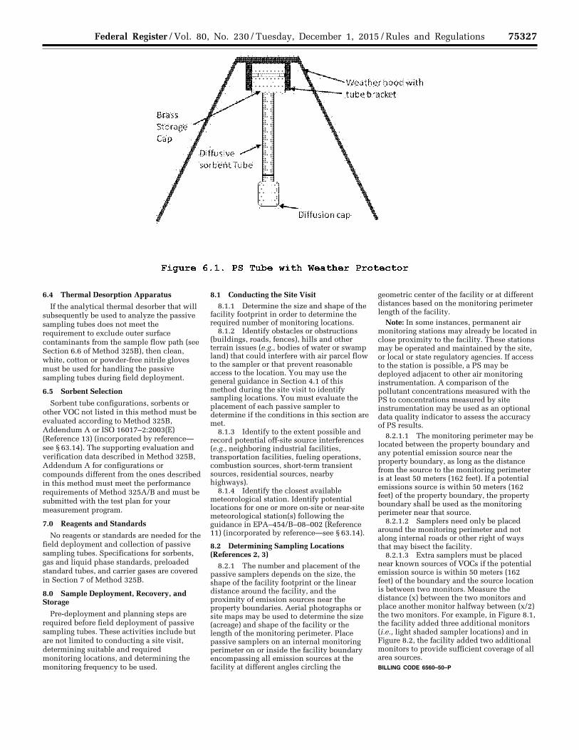
75327 Federal Register / Vol. 80, No. 230 / Tuesday, December 1, 2015 / Rules and Regulations
6.4 Thermal Desorption Apparatus
If the analytical thermal desorber that will subsequently be used to analyze the passive sampling tubes does not meet the requirement to exclude outer surface contaminants from the sample flow path (see Section 6.6 of Method 325B), then clean, white, cotton or powder-free nitrile gloves must be used for handling the passive sampling tubes during field deployment.
6.5 Sorbent Selection
Sorbent tube configurations, sorbents or other VOC not listed in this method must be evaluated according to Method 325B, Addendum A or ISO 16017–2:2003(E) (Reference 13) (incorporated by reference— see § 63.14). The supporting evaluation and verification data described in Method 325B, Addendum A for configurations or compounds different from the ones described in this method must meet the performance requirements of Method 325A/B and must be submitted with the test plan for your measurement program.
7.0 Reagents and Standards
No reagents or standards are needed for the field deployment and collection of passive sampling tubes. Specifications for sorbents, gas and liquid phase standards, preloaded standard tubes, and carrier gases are covered in Section 7 of Method 325B.
8.0 Sample Deployment, Recovery, and Storage
Pre-deployment and planning steps are required before field deployment of passive sampling tubes. These activities include but are not limited to conducting a site visit, determining suitable and required monitoring locations, and determining the monitoring frequency to be used.
8.1 Conducting the Site Visit 8.1.1 Determine the size and shape of the
facility footprint in order to determine the required number of monitoring locations.
8.1.2 Identify obstacles or obstructions (buildings, roads, fences), hills and other terrain issues (e.g., bodies of water or swamp land) that could interfere with air parcel flow to the sampler or that prevent reasonable access to the location. You may use the general guidance in Section 4.1 of this method during the site visit to identify sampling locations. You must evaluate the placement of each passive sampler to determine if the conditions in this section are met.
8.1.3 Identify to the extent possible and record potential off-site source interferences (e.g., neighboring industrial facilities, transportation facilities, fueling operations, combustion sources, short-term transient sources, residential sources, nearby highways).
8.1.4 Identify the closest available meteorological station. Identify potential locations for one or more on-site or near-site meteorological station(s) following the guidance in EPA–454/B–08–002 (Reference 11) (incorporated by reference—see § 63.14).
8.2 Determining Sampling Locations (References 2, 3)
8.2.1 The number and placement of the passive samplers depends on the size, the shape of the facility footprint or the linear distance around the facility, and the proximity of emission sources near the property boundaries. Aerial photographs or site maps may be used to determine the size (acreage) and shape of the facility or the length of the monitoring perimeter. Place passive samplers on an internal monitoring perimeter on or inside the facility boundary encompassing all emission sources at the facility at different angles circling the
geometric center of the facility or at different distances based on the monitoring perimeter length of the facility.
Note: In some instances, permanent air monitoring stations may already be located in close proximity to the facility. These stations may be operated and maintained by the site, or local or state regulatory agencies. If access to the station is possible, a PS may be deployed adjacent to other air monitoring instrumentation. A comparison of the pollutant concentrations measured with the PS to concentrations measured by site instrumentation may be used as an optional data quality indicator to assess the accuracy of PS results.
8.2.1.1 The monitoring perimeter may be located between the property boundary and any potential emission source near the property boundary, as long as the distance from the source to the monitoring perimeter is at least 50 meters (162 feet). If a potential emissions source is within 50 meters (162 feet) of the property boundary, the property boundary shall be used as the monitoring perimeter near that source.
8.2.1.2 Samplers need only be placed around the monitoring perimeter and not along internal roads or other right of ways that may bisect the facility.
8.2.1.3 Extra samplers must be placed near known sources of VOCs if the potential emission source is within 50 meters (162 feet) of the boundary and the source location is between two monitors. Measure the distance (x) between the two monitors and place another monitor halfway between (x/2) the two monitors. For example, in Figure 8.1, the facility added three additional monitors (i.e., light shaded sampler locations) and in Figure 8.2, the facility added two additional monitors to provide sufficient coverage of all area sources. BILLING CODE 6560–50–P
VerDate Sep<11>2014 23:11 Nov 30, 2015 Jkt 238001 PO 00000 Frm 00151 Fmt 4701 Sfmt 4700 E:\FR\FM\01DER2.SGM 01DER2 ER
01D
E15
.025
</G
PH
>
tkel
ley
on D
SK
3SP
TV
N1P
RO
D w
ith R
ULE
S2

75328 Federal Register / Vol. 80, No. 230 / Tuesday, December 1, 2015 / Rules and Regulations
8.2.2 Option 1 for Determining Sampling Locations.
8.2.2.1 For facilities with a regular (circular, triangular, rectangular, or square)
shape, determine the geographic center of the facility.
VerDate Sep<11>2014 23:11 Nov 30, 2015 Jkt 238001 PO 00000 Frm 00152 Fmt 4701 Sfmt 4700 E:\FR\FM\01DER2.SGM 01DER2 ER
01D
E15
.026
</G
PH
>
tkel
ley
on D
SK
3SP
TV
N1P
RO
D w
ith R
ULE
S2
~ 0
:!:: c 0 E ro c 0
:-e "'0 "'0 <(
Refinery (20% Angle)
Note: Shaded sources are within 50 meters of the property boundary and are located between two monitors. Additional coverage required by this method was accomplished by placing the monitors halfway between two existing monitors.
Figure 8.1. Facility with a Regular Shape Between 750 and 1,500 Acres in Area
(f)
(f)
(f)
(f)
(f)
Refinery (24,000 Feet Perimeter)
Note: Shaded sources are within 50 meters of the property boundary and are located between two monitors. Additional coverqe required by this method was accomplished by placing the monitors halfway between two existing monitors.
Figure 8.2. Facility with a Boundary Length of 24,000 feet

75329 Federal Register / Vol. 80, No. 230 / Tuesday, December 1, 2015 / Rules and Regulations
8.2.2.1.1 For facilities with an area of less than or equal to 750 acres, measure angles of 30 degrees from the center point for a total of twelve 30 degree measurements evenly spaced (±1 degree).
8.2.2.1.2 For facilities covering an area greater than 750 acres but less than or equal to 1,500 acres, measure angles of 20 degrees from the center point for a total of eighteen 20 degree measurements evenly spaced (±1 degree). Figure 8.1 shows the monitor placement around the property boundary of a facility with an area between 750 and 1,500
acres. Monitor placements are represented with black dots along the property boundary.
8.2.2.1.3 For facilities covering an area greater than 1,500 acres, measure angles of 15 degrees from the center point for a total of twenty-four 15 degree measurements evenly spaced (±1 degree).
8.2.2.1.4 Locate each sampling point where the measured angle intersects the outer monitoring perimeter.
8.2.2.2 For irregularly shaped facilities, divide the area into a set of connecting subarea circles, triangles or rectangles to
determine sampling locations. The subareas must be defined such that a circle can reasonably encompass the subarea. Then determine the geometric center point of each of the subareas.
8.2.2.2.1 If a subarea is less than or equal to 750 acres (e.g., Figure 8.3), measure angles of 30 degrees from the center point for a total of twelve 30 degree measurements (±1 degree).
8.2.2.2.2 If a subarea is greater than 750 acres but less than or equal to 1,500 acres (e.g., Figure 8.4), measure angles of 20 degrees from the center point for a total of eighteen 20 degree measurements (±1 degree).
8.2.2.2.3 If a subarea is greater than 1,500 acres, measure angles of 15 degrees from the
center for a total of twenty-four 15 degree measurements (±1 degree).
8.2.2.2.4 Locate each sampling point where the measured angle intersects the outer monitoring perimeter. Sampling points need not be placed closer than 152 meters (500 feet) apart (or 76 meters (250 feet) if known sources are within 50 meters (162
feet) of the monitoring perimeter), as long as a minimum of 3 monitoring locations are used for each subarea.
8.2.2.2.5 Sampling sites are not needed at the intersection of an inner boundary with an adjacent subarea. The sampling location must be sited where the measured angle intersects the subarea’s outer monitoring perimeter.
VerDate Sep<11>2014 23:11 Nov 30, 2015 Jkt 238001 PO 00000 Frm 00153 Fmt 4701 Sfmt 4700 E:\FR\FM\01DER2.SGM 01DER2 ER
01D
E15
.027
</G
PH
>
tkel
ley
on D
SK
3SP
TV
N1P
RO
D w
ith R
ULE
S2

75330 Federal Register / Vol. 80, No. 230 / Tuesday, December 1, 2015 / Rules and Regulations
8.2.3 Option 2 for Determining Sampling Locations.
8.2.3.1 For facilities with a monitoring perimeter length of less than 7,315 meters (24,000 feet), a minimum of twelve sampling locations evenly spaced ±10 percent of the location interval is required.
8.2.3.2 For facilities with a monitoring perimeter length greater than 7,315 meters (24,000 feet), sampling locations are spaced 610 ±76 meters (2,000 ± 250 feet) apart.
8.3 Siting a Meteorological Station A meteorological station is required at or
near the facility you are monitoring. A number of commercially available meteorological stations can be used. Information on meteorological instruments can be found in EPA–454/R–99–005 (Reference 11) (incorporated by reference— see § 63.14). Some important considerations for siting of meteorological stations are detailed below.
8.3.1 Place meteorological stations in locations that represent conditions affecting the transport and dispersion of pollutants in the area of interest. Complex terrain may require the use of more than one meteorological station.
8.3.2 Deploy wind instruments over level, open terrain at a height of 10 meters (33 feet). If possible, locate wind instruments at a distance away from nearby structures that is equal to at least 10 times the height of the structure.
8.3.3 Protect meteorological instruments from thermal radiation and adequately ventilate them using aspirated shields. The temperature sensor must be located at a distance away from any nearby structures that is equal to at least four times the height
of the structure. Temperature sensors must be located at least 30 meters (98 feet) from large paved areas.
8.3.4 Collect and record meteorological data, including wind speed, wind direction, temperature and barometric pressure on an hourly basis. Calculate average unit vector wind direction, sigma theta, temperature and barometric pressure per sampling period to enable calculation of concentrations at standard conditions. Supply this information to the laboratory.
8.3.5 Identify and record the location of the meteorological station by its GPS coordinate.
8.4 Monitoring Frequency 8.4.1 Sample collection may be
performed for periods up to 14 days. 8.4.2 A site screening protocol that meets
method requirements may be performed by collecting samples for a year where each PS accumulates VOC for a 14-day sampling period. Study results are accumulated for the sampling periods (typically 26) over the course of one calendar year. To the extent practical, sampling tubes should be changed at approximately the same time of day at each of the monitoring sites.
8.5 Passive Sampler Deployment
8.5.1 Clean (conditioned) sorbent tubes must be prepared and packaged by the laboratory as described in Method 325B and must be deployed for sampling within 30 days of conditioning.
8.5.2 Allow the tubes to equilibrate with ambient temperature (approximately 30 minutes to 1 hour) at the monitoring location before removing them from their storage/shipping container for sample collection.
8.5.3 If there is any risk that the analytical equipment will not meet the requirement to exclude contamination on outer tube surfaces from the sample flow path (see Section 6.6 of Method 325B), sample handlers must wear clean, white, cotton or powder-free nitrile gloves during PS deployment and collection and throughout any other tube handling operations.
8.5.4 Inspect the sampling tubes immediately prior to deployment. Ensure that they are intact, securely capped, and in good condition. Any suspect tubes (e.g., tubes that appear to have leaked sorbent) should be removed from the sampling set.
8.5.5 Secure passive samplers so the bottom of the diffusive sampling cap is 1.5 to 3 meters (4.9 to 9.8 feet) above ground using a pole or other secure structure at each sampling location. Orient the PS vertically and with the sampling end pointing downward to avoid ingress of particulates.
Note: Duplicate sampling assemblies must be deployed in at least one monitoring location for every 10 monitoring locations during each field monitoring period.
8.5.6 Protect the PS from rain and excessive wind velocity by placing them under the type of protective hood described in Section 6.1.3 or equivalent.
8.5.7 Remove the storage cap on the sampling end of the tube and replace it with a diffusive sampling cap at the start of the sampling period. Make sure the diffusion cap is properly seated and store the removed storage caps in the empty tube shipping container.
8.5.8 Record the start time and location details for each sampler on the field sample data sheet (see example in Section 17.0.).
VerDate Sep<11>2014 23:11 Nov 30, 2015 Jkt 238001 PO 00000 Frm 00154 Fmt 4701 Sfmt 4700 E:\FR\FM\01DER2.SGM 01DER2 ER
01D
E15
.028
</G
PH
>
tkel
ley
on D
SK
3SP
TV
N1P
RO
D w
ith R
ULE
S2
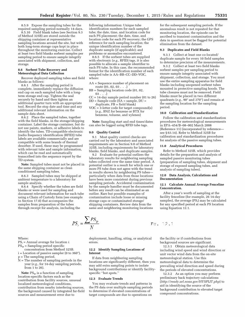
75331 Federal Register / Vol. 80, No. 230 / Tuesday, December 1, 2015 / Rules and Regulations
8.5.9 Expose the sampling tubes for the required sampling period-normally 14-days.
8.5.10 Field blank tubes (see Section 9.3 of Method 325B) are stored outside the shipping container at representative sampling locations around the site, but with both long-term storage caps kept in place throughout the monitoring exercise. Collect at least two field blanks sorbent samples per sampling period to ensure sample integrity associated with shipment, collection, and storage.
8.6 Sorbent Tube Recovery and Meteorological Data Collection
Recover deployed sampling tubes and field blanks as follows:
8.6.1 After the sampling period is complete, immediately replace the diffusion end cap on each sampled tube with a long- term storage end cap. Tighten the seal securely by hand and then tighten an additional quarter turn with an appropriate tool. Record the stop date and time and any additional relevant information on the sample data sheet.
8.6.2 Place the sampled tubes, together with the field blanks, in the storage/shipping container. Label the storage container, but do not use paints, markers, or adhesive labels to identify the tubes. TD-compatible electronic (radio frequency identification (RFID)) tube labels are available commercially and are compatible with some brands of thermal desorber. If used, these may be programmed with relevant tube and sample information, which can be read and automatically transcribed into the sequence report by the TD system.
Note: Sampled tubes must not be placed in the same shipping container as clean conditioned sampling tubes.
8.6.3 Sampled tubes may be shipped at ambient temperature to a laboratory for sample analysis.
8.6.4 Specify whether the tubes are field blanks or were used for sampling and document relevant information for each tube using a Chain of Custody form (see example in Section 17.0) that accompanies the samples from preparation of the tubes through receipt for analysis, including the
following information: Unique tube identification numbers for each sampled tube; the date, time, and location code for each PS placement; the date, time, and location code for each PS recovery; the GPS reference for each sampling location; the unique identification number of the duplicate sample (if applicable); and problems or anomalies encountered.
8.6.5 If the sorbent tubes are supplied with electronic (e.g., RFID) tags, it is also possible to allocate a sample identifier to each PS tube. In this case, the recommended format for the identification number of each sampled tube is AA–BB–CC–DD–VOC, where:
AA = Sequence number of placement on route (01, 02, 03 . . .)
BB = Sampling location code (01, 02, 03 . . .)
CC = 14-day sample period number (01 to 26) DD = Sample code (SA = sample, DU =
duplicate, FB = field blank) VOC = 3-letter code for target compound(s)
(e.g., BNZ for benzene or BTX for benzene, toluene, and xylenes)
Note: Sampling start and end times/dates can also be logged using RFID tube tags.
9.0 Quality Control 9.1 Most quality control checks are
carried out by the laboratory and associated requirements are in Section 9.0 of Method 325B, including requirements for laboratory blanks, field blanks, and duplicate samples.
9.2 Evaluate for potential outliers the laboratory results for neighboring sampling tubes collected over the same time period. A potential outlier is a result for which one or more PS tube does not agree with the trend in results shown by neighboring PS tubes— particularly when data from those locations have been more consistent during previous sampling periods. Accidental contamination by the sample handler must be documented before any result can be eliminated as an outlier. Rare but possible examples of contamination include loose or missing storage caps or contaminated storage/shipping containers. Review data from the same and neighboring monitoring locations
for the subsequent sampling periods. If the anomalous result is not repeated for that monitoring location, the episode can be ascribed to transient contamination and the data in question must be flagged for potential elimination from the dataset.
9.3 Duplicates and Field Blanks
9.3.1 Collect at least one co-located/duplicate sample for every 10 field samples to determine precision of the measurements.
9.3.2 Collect at least two field blanks sorbent samples per sampling period to ensure sample integrity associated with shipment, collection, and storage. You must use the entire sampling apparatus for field blanks including unopened sorbent tubes mounted in protective sampling hoods. The tube closures must not be removed. Field blanks must be placed in two different quadrants (e.g., 90° and 270°) and remain at the sampling location for the sampling period.
10.0 Calibration and Standardization
Follow the calibration and standardization procedures for meteorological measurements in EPA–454/B–08–002 March 2008 (Reference 11) (incorporated by reference— see § 63.14). Refer to Method 325B for calibration and standardization procedures for analysis of the passive sampling tubes.
11.0 Analytical Procedures
Refer to Method 325B, which provides details for the preparation and analysis of sampled passive monitoring tubes (preparation of sampling tubes, shipment and storage of exposed sampling tubes, and analysis of sampling tubes).
12.0 Data Analysis, Calculations and Documentation
12.1 Calculate Annual Average Fenceline Concentration.
After a year’s worth of sampling at the facility fenceline (for example, 26 14-day samples), the average (PSi) may be calculated for any specified period at each PS location using Equation 12.1.
Where: PSi = Annual average for location i. PSip = Sampling period specific
concentration from Method 325B. i = Location of passive sampler (0 to 360°). p = The sampling period. N = The number of sampling periods in the
year (e.g., for 14-day sampling periods, from 1 to 26).
Note: PSip is a function of sampling location-specific factors such as the contribution from facility sources, unusual localized meteorological conditions, contribution from nearby interfering sources, the background caused by integrated far-field sources and measurement error due to
deployment, handling, siting, or analytical errors.
12.2 Identify Sampling Locations of Interest
If data from neighboring sampling locations are significantly different, then you may add extra sampling points to isolate background contributions or identify facility- specific ‘‘hot spots.’’
12.3 Evaluate Trends
You may evaluate trends and patterns in the PS data over multiple sampling periods to determine if elevated concentrations of target compounds are due to operations on
the facility or if contributions from background sources are significant.
12.3.1 Obtain meteorological data including wind speed and wind direction or unit vector wind data from the on-site meteorological station. Use this meteorological data to determine the prevailing wind direction and speed during the periods of elevated concentrations.
12.3.2 As an option you may perform preliminary back trajectory calculations (http://ready.arl.noaa.gov/HYSPLIT.php) to aid in identifying the source of the background contribution to elevated target compound concentrations.
VerDate Sep<11>2014 23:11 Nov 30, 2015 Jkt 238001 PO 00000 Frm 00155 Fmt 4701 Sfmt 4700 E:\FR\FM\01DER2.SGM 01DER2 ER
01D
E15
.029
</G
PH
>
tkel
ley
on D
SK
3SP
TV
N1P
RO
D w
ith R
ULE
S2
75332 Federal Register / Vol. 80, No. 230 / Tuesday, December 1, 2015 / Rules and Regulations
12.3.3 Information on published or documented events on- and off-site may also be included in the associated sampling period report to explain elevated concentrations if relevant. For example, you would describe if there was a chemical spill on site, or an accident on an adjacent road.
12.3.4 Additional monitoring for shorter periods (See section 8.4) may be necessary to allow better discrimination/resolution of contributing emission sources if the measured trends and associated meteorology do not provide a clear assessment of facility contribution to the measured fenceline concentration.
12.3.5 Additional records necessary to calculate sampling period average target compound concentration can be found in Section 12.1 of Method 325B.
13.0 Method Performance Method performance requirements are
described in Method 325B.
14.0 Pollution Prevention [Reserved]
15.0 Waste Management [Reserved]
16.0 References 1. Ambient air quality—Standard method for
measurement of benzene concentrations—Part 4: Diffusive sampling followed by thermal desorption and gas chromatography, BS EN 14662– 4:2005.
2. Thoma, E.D., Miller, C.M., Chung, K.C., Parsons, N.L. and Shine, B.C. Facility
Fence Line Monitoring using Passive Samplers, J. Air & Waste Mange. Assoc. 2011, 61:834–842.
3. Quality Assurance Handbook for Air Pollution C Systems, Volume II: Ambient Air Quality Monitoring Program, EPA– 454/B–13–003, May 2013. Available at http://www.epa.gov/ttnamti1/files/ambient/pm25/qa/QA-Handbook-Vol- II.pdf.
4. Brown, R.H., Charlton, J. and Saunders, K.J.: The development of an improved diffusive sampler. Am. Ind. Hyg. Assoc. J. 1981, 42(12): 865–869.
5. Brown, R. H. Environmental use of diffusive samplers: evaluation of reliable diffusive uptake rates for benzene, toluene and xylene. J. Environ. Monit. 1999, 1 (1), 115–116.
6. Ballach, J.; Greuter, B.; Schultz, E.; Jaeschke, W. Variations of uptake rates in benzene diffusive sampling as a function of ambient conditions. Sci. Total Environ. 1999, 244, 203–217.
7. Brown, R. H. Monitoring the ambient environment with diffusive samplers: theory and practical considerations. J Environ. Monit. 2000, 2 (1), 1–9.
8. Buzica, D.; Gerboles, M.; Plaisance, H. The equivalence of diffusive samplers to reference methods for monitoring O3, benzene and NO2 in ambient air. J. Environ. Monit. 2008, 10 (9), 1052–1059.
9. Woolfenden, E. Sorbent-based sampling methods for volatile and semi-volatile organic compounds in air. Part 2. Sorbent selection and other aspects of optimizing air monitoring methods. J.
Chromatogr. A 2010, 1217, (16), 2685– 94.
10. Pfeffer, H. U.; Breuer, L. BTX measurements with diffusive samplers in the vicinity of a cokery: Comparison between ORSA-type samplers and pumped sampling. J. Environ. Monit. 2000, 2 (5), 483–486.
11. US EPA. 2000. Meteorological Monitoring Guidance for Regulatory Modeling Applications. EPA–454/R–99–005. Office of Air Quality Planning and Standards, Research Triangle Park, NC. February 2000. Available at http://www.epa.gov/scram001/guidance/met/mmgrma.pdf.
12. Quality Assurance Handbook for Air Pollution Measurement Systems. Volume IV: Meteorological Measurements Version 2.0 Final, EPA–454/B–08–002 March 2008. Available at http://www.epa.gov/ttnamti1/files/ambient/met/Volume%20IV_Meteorological_Measurements.pdf.
13. ISO 16017–2:2003(E), Indoor, ambient and workplace air—Sampling and analysis of volatile organic compounds by sorbent tube/thermal desorption/capillary gas chromatography. Part 2: Diffusive sampling.
14. ASTM D6196–03 (Reapproved 2009): Standard practice for selection of sorbents, sampling, and thermal desorption analysis procedures for volatile organic compounds in air.
17.0 Tables, Diagrams, Flowcharts and Validation Data
VerDate Sep<11>2014 23:11 Nov 30, 2015 Jkt 238001 PO 00000 Frm 00156 Fmt 4701 Sfmt 4700 E:\FR\FM\01DER2.SGM 01DER2tkel
ley
on D
SK
3SP
TV
N1P
RO
D w
ith R
ULE
S2

75333 Federal Register / Vol. 80, No. 230 / Tuesday, December 1, 2015 / Rules and Regulations
VerDate Sep<11>2014 23:11 Nov 30, 2015 Jkt 238001 PO 00000 Frm 00157 Fmt 4701 Sfmt 4725 E:\FR\FM\01DER2.SGM 01DER2 ER
01D
E15
.030
</G
PH
>
tkel
ley
on D
SK
3SP
TV
N1P
RO
D w
ith R
ULE
S2
Method 325 A/B
EXAMPLE FIELD TEST DATA SHEET (FTDS) AND
CHAIN OF CUSTODY
I. GENERAL INFORMATION
SITE NAME:
SITE LOCATION ADDRESS:
CITY: STATE: ZIP:
II. SAMPLING DATA
Sample Ambient ID Sample Barometric
(Tube) or Start Start Stop Stop Location Temp. Pressure # Sorbent blank Date Time Date Time (gps) (oF) (in. Hg)
III. CUSTODY INFORMATION
COLLECTED BY: Relinquished to Shipper -Name: Date: Time Received by Laboratory -Name Date: Time Sample condition upon receipt:
Analysis Required:
Comments:
Figure 17.1. Example Field Data Form and Chain of Custody
75334 Federal Register / Vol. 80, No. 230 / Tuesday, December 1, 2015 / Rules and Regulations
Method 325B—Volatile Organic Compounds from Fugitive and Area Sources:
Sampler Preparation and Analysis
1.0 Scope and Application 1.1 This method describes thermal
desorption/gas chromatography (TD/GC) analysis of volatile organic compounds (VOCs) from fugitive and area emission sources collected onto sorbent tubes using passive sampling. It could also be applied to the TD/GC analysis of VOCs collected using active (pumped) sampling onto sorbent tubes. The concentration of airborne VOCs at or near potential fugitive- or area-emission sources may be determined using this method in combination with Method 325A. Companion Method 325A (Sampler Deployment and VOC Sample Collection) describes procedures for deploying the sorbent tubes and passively collecting VOCs.
1.2 The preferred GC detector for this method is a mass spectrometer (MS), but flame ionization detectors (FID) may also be used. Other conventional GC detectors such as electron capture (ECD), photoionization (PID), or flame photometric (FPD) may also be used if they are selective and sensitive to the target compound(s) and if they meet the method performance criteria provided in this method.
1.3 There are 97 VOCs listed as hazardous air pollutants in Title III of the Clean Air Act Amendments of 1990. Many of these VOC are candidate compounds for this method. Compounds with known uptake rates for CarbographTM 1 TD, CarbopackTM B, or CarbopackTM X are listed in Table 12.1. This method provides performance criteria to demonstrate acceptable performance of the method (or modifications of the method) for monitoring one or more of the compounds listed Table 12.1. If standard passive sampling tubes are packed with other sorbents or used for other analytes than those listed in Table 12.1, then method performance and relevant uptake rates should be verified according to Addendum A to this method or by one of the following national/international standard methods: ISO 16017–2:2003(E), ASTM D6196–03 (Reapproved 2009), or BS EN 14662–4:2005 (all incorporated by reference—see § 63.14), or reported in the peer-reviewed open literature.
1.4 The analytical approach using TD/GC/MS is based on previously published EPA guidance in Compendium Method TO– 17 (http://www.epa.gov/ttnamti1/airtox.html#compendium) (Reference 1), which describes active (pumped) sampling of VOCs from ambient air onto tubes packed with thermally stable adsorbents.
1.5 Inorganic gases not suitable for analysis by this method include oxides of carbon, nitrogen and sulfur, ozone (O3), and other diatomic permanent gases. Other pollutants not suitable for this analysis method include particulate pollutants, (i.e., fumes, aerosols, and dusts), compounds too labile (reactive) for conventional GC analysis, and VOCs that are more volatile than propane.
2.0 Summary of Method 2.1 This method provides procedures for
the preparation, conditioning, blanking, and
shipping of sorbent tubes prior to sample collection.
2.2 Laboratory and field personnel must have experience of sampling trace-level VOCs using sorbent tubes (References 2,5) and must have experience operating thermal desorption/GC/multi-detector instrumentation.
2.3 Key steps of this method as implemented for each sample tube include: Stringent leak testing under stop flow, recording ambient temperature conditions, adding internal standards, purging the tube, thermally desorbing the sampling tube, refocusing on a focusing trap, desorbing and transferring/injecting the VOCs from the secondary trap into the capillary GC column for separation and analysis.
2.4 Water management steps incorporated into this method include: (a) Selection of hydrophobic sorbents in the sampling tube; (b) optional dry purging of sample tubes prior to analysis; and (c) additional selective elimination of water during primary (tube) desorption (if required) by selecting trapping sorbents and temperatures such that target compounds are quantitatively retained while water is purged to vent.
3.0 Definitions
(See also Section 3.0 of Method 325A). 3.1 Blanking is the desorption and
confirmatory analysis of conditioned sorbent tubes before they are sent for field sampling.
3.2 Breakthrough volume and associated relation to passive sampling. Breakthrough volumes, as applied to active sorbent tube sampling, equate to the volume of air containing a constant concentration of analyte that may be passed through a sorbent tube at a given temperature before a detectable level (5 percent) of the input analyte concentration elutes from the tube. Although breakthrough volumes are directly related to active rather than passive sampling, they provide a measure of the strength of the sorbent-sorbate interaction and therefore also relate to the efficiency of the passive sampling process. The best direct measure of passive sampling efficiency is the stability of the uptake rate. Quantitative passive sampling is compromised when the sorbent no longer acts as a perfect sink—i.e., when the concentration of a target analyte immediately above the sorbent sampling surface no longer approximates to zero. This causes a reduction in the uptake rate over time. If the uptake rate for a given analyte on a given sorbent tube remains relatively constant —i.e., if the uptake rate determined for 48 hours is similar to that determined for 7 or 14 days—the user can be confident that passive sampling is occurring at a constant rate. As a general rule of thumb, such ideal passive sampling conditions typically exist for analyte:sorbent combinations where the breakthrough volume exceeds 100 L (Reference 4).
3.3 Continuing calibration verification sample (CCV). Single level calibration samples run periodically to confirm that the analytical system continues to generate sample results within acceptable agreement to the current calibration curve.
3.4 Focusing trap is a cooled, secondary sorbent trap integrated into the analytical
thermal desorber. It typically has a smaller i.d. and lower thermal mass than the original sample tube allowing it to effectively refocus desorbed analytes and then heat rapidly to ensure efficient transfer/injection into the capillary GC analytical column.
3.5 High Resolution Capillary Column Chromatography uses fused silica capillary columns with an inner diameter of 320 mm or less and with a stationary phase film thickness of 5 mm or less.
3.6 h is time in hours. 3.7 i.d. is inner diameter. 3.8 min is time in minutes. 3.9 Method Detection Limit is the lowest
level of analyte that can be detected in the sample matrix with 99% confidence.
3.10 MS–SCAN is the mode of operation of a GC quadrupole mass spectrometer detector that measures all ions over a given mass range over a given period of time.
3.11 MS–SIM is the mode of operation of a GC quadrupole mass spectrometer detector that measures only a single ion or a selected number of discrete ions for each analyte.
3.12 o.d. is outer diameter. 3.13 ppbv is parts per billion by volume. 3.14 Thermal desorption is the use of
heat and a flow of inert (carrier) gas to extract volatiles from a solid matrix. No solvent is required.
3.15 Total ion chromatogram is the chromatogram produced from a mass spectrometer detector collecting full spectral information.
3.16 Two-stage thermal desorption is the process of thermally desorbing analytes from a sorbent tube, reconcentrating them on a focusing trap (see Section 3.4), which is then itself rapidly heated to ‘‘inject’’ the concentrated compounds into the GC analyzer.
3.17 VOC is volatile organic compound.
4.0 Analytical Interferences 4.1 Interference from Sorbent Artifacts.
Artifacts may include target analytes as well as other VOC that co-elute chromatographically with the compounds of interest or otherwise interfere with the identification or quantitation of target analytes.
4.1.1 Sorbent decomposition artifacts are VOCs that form when sorbents degenerate, e.g., when exposed to reactive species during sampling. For example, benzaldehyde, phenol, and acetophenone artifacts are reported to be formed via oxidation of the polymeric sorbent Tenax® when sampling high concentration (100–500 ppb) ozone atmospheres (Reference 5).
4.1.2 Preparation and storage artifacts are VOCs that were not completely cleaned from the sorbent tube during conditioning or that are an inherent feature of that sorbent at a given temperature.
4.2 Humidity. Moisture captured during sampling can interfere with VOC analysis. Passive sampling using tubes packed with hydrophobic sorbents, like those described in this method, minimizes water retention. However, if water interference is found to be an issue under extreme conditions, one or more of the water management steps described in Section 2.4 can be applied.
4.3 Contamination from Sample Handling. The type of analytical thermal
VerDate Sep<11>2014 23:11 Nov 30, 2015 Jkt 238001 PO 00000 Frm 00158 Fmt 4701 Sfmt 4700 E:\FR\FM\01DER2.SGM 01DER2tkel
ley
on D
SK
3SP
TV
N1P
RO
D w
ith R
ULE
S2
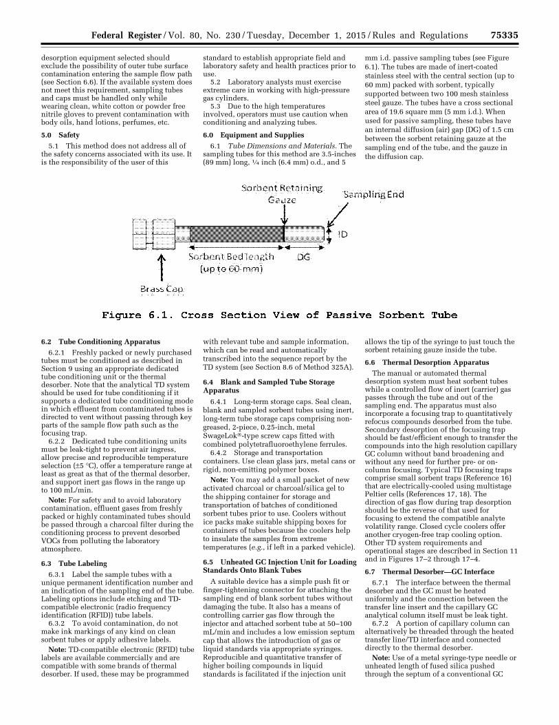
75335 Federal Register / Vol. 80, No. 230 / Tuesday, December 1, 2015 / Rules and Regulations
desorption equipment selected should exclude the possibility of outer tube surface contamination entering the sample flow path (see Section 6.6). If the available system does not meet this requirement, sampling tubes and caps must be handled only while wearing clean, white cotton or powder free nitrile gloves to prevent contamination with body oils, hand lotions, perfumes, etc.
5.0 Safety 5.1 This method does not address all of
the safety concerns associated with its use. It is the responsibility of the user of this
standard to establish appropriate field and laboratory safety and health practices prior to use.
5.2 Laboratory analysts must exercise extreme care in working with high-pressure gas cylinders.
5.3 Due to the high temperatures involved, operators must use caution when conditioning and analyzing tubes.
6.0 Equipment and Supplies 6.1 Tube Dimensions and Materials. The
sampling tubes for this method are 3.5-inches (89 mm) long, 1⁄4 inch (6.4 mm) o.d., and 5
mm i.d. passive sampling tubes (see Figure 6.1). The tubes are made of inert-coated stainless steel with the central section (up to 60 mm) packed with sorbent, typically supported between two 100 mesh stainless steel gauze. The tubes have a cross sectional area of 19.6 square mm (5 mm i.d.). When used for passive sampling, these tubes have an internal diffusion (air) gap (DG) of 1.5 cm between the sorbent retaining gauze at the sampling end of the tube, and the gauze in the diffusion cap.
6.2 Tube Conditioning Apparatus 6.2.1 Freshly packed or newly purchased
tubes must be conditioned as described in Section 9 using an appropriate dedicated tube conditioning unit or the thermal desorber. Note that the analytical TD system should be used for tube conditioning if it supports a dedicated tube conditioning mode in which effluent from contaminated tubes is directed to vent without passing through key parts of the sample flow path such as the focusing trap.
6.2.2 Dedicated tube conditioning units must be leak-tight to prevent air ingress, allow precise and reproducible temperature selection (±5 °C), offer a temperature range at least as great as that of the thermal desorber, and support inert gas flows in the range up to 100 mL/min.
Note: For safety and to avoid laboratory contamination, effluent gases from freshly packed or highly contaminated tubes should be passed through a charcoal filter during the conditioning process to prevent desorbed VOCs from polluting the laboratory atmosphere.
6.3 Tube Labeling 6.3.1 Label the sample tubes with a
unique permanent identification number and an indication of the sampling end of the tube. Labeling options include etching and TD- compatible electronic (radio frequency identification (RFID)) tube labels.
6.3.2 To avoid contamination, do not make ink markings of any kind on clean sorbent tubes or apply adhesive labels.
Note: TD-compatible electronic (RFID) tube labels are available commercially and are compatible with some brands of thermal desorber. If used, these may be programmed
with relevant tube and sample information, which can be read and automatically transcribed into the sequence report by the TD system (see Section 8.6 of Method 325A).
6.4 Blank and Sampled Tube Storage Apparatus
6.4.1 Long-term storage caps. Seal clean, blank and sampled sorbent tubes using inert, long-term tube storage caps comprising non- greased, 2-piece, 0.25-inch, metal SwageLok®-type screw caps fitted with combined polytetrafluoroethylene ferrules.
6.4.2 Storage and transportation containers. Use clean glass jars, metal cans or rigid, non-emitting polymer boxes.
Note: You may add a small packet of new activated charcoal or charcoal/silica gel to the shipping container for storage and transportation of batches of conditioned sorbent tubes prior to use. Coolers without ice packs make suitable shipping boxes for containers of tubes because the coolers help to insulate the samples from extreme temperatures (e.g., if left in a parked vehicle).
6.5 Unheated GC Injection Unit for Loading Standards Onto Blank Tubes
A suitable device has a simple push fit or finger-tightening connector for attaching the sampling end of blank sorbent tubes without damaging the tube. It also has a means of controlling carrier gas flow through the injector and attached sorbent tube at 50–100 mL/min and includes a low emission septum cap that allows the introduction of gas or liquid standards via appropriate syringes. Reproducible and quantitative transfer of higher boiling compounds in liquid standards is facilitated if the injection unit
allows the tip of the syringe to just touch the sorbent retaining gauze inside the tube.
6.6 Thermal Desorption Apparatus The manual or automated thermal
desorption system must heat sorbent tubes while a controlled flow of inert (carrier) gas passes through the tube and out of the sampling end. The apparatus must also incorporate a focusing trap to quantitatively refocus compounds desorbed from the tube. Secondary desorption of the focusing trap should be fast/efficient enough to transfer the compounds into the high resolution capillary GC column without band broadening and without any need for further pre- or on- column focusing. Typical TD focusing traps comprise small sorbent traps (Reference 16) that are electrically-cooled using multistage Peltier cells (References 17, 18). The direction of gas flow during trap desorption should be the reverse of that used for focusing to extend the compatible analyte volatility range. Closed cycle coolers offer another cryogen-free trap cooling option. Other TD system requirements and operational stages are described in Section 11 and in Figures 17–2 through 17–4.
6.7 Thermal Desorber—GC Interface 6.7.1 The interface between the thermal
desorber and the GC must be heated uniformly and the connection between the transfer line insert and the capillary GC analytical column itself must be leak tight.
6.7.2 A portion of capillary column can alternatively be threaded through the heated transfer line/TD interface and connected directly to the thermal desorber.
Note: Use of a metal syringe-type needle or unheated length of fused silica pushed through the septum of a conventional GC
VerDate Sep<11>2014 23:11 Nov 30, 2015 Jkt 238001 PO 00000 Frm 00159 Fmt 4701 Sfmt 4700 E:\FR\FM\01DER2.SGM 01DER2 ER
01D
E15
.031
</G
PH
>
tkel
ley
on D
SK
3SP
TV
N1P
RO
D w
ith R
ULE
S2
75336 Federal Register / Vol. 80, No. 230 / Tuesday, December 1, 2015 / Rules and Regulations
injector is not permitted as a means of interfacing the thermal desorber to the chromatograph. Such connections result in cold spots, cause band broadening and are prone to leaks.
6.8 GC/MS Analytical Components 6.8.1 The GC system must be capable of
temperature programming and operation of a high resolution capillary column. Depending on the choice of column (e.g., film thickness) and the volatility of the target compounds, it may be necessary to cool the GC oven to subambient temperatures (e.g., ¥50 °C) at the start of the run to allow resolution of very volatile organic compounds.
6.8.2 All carrier gas lines supplying the GC must be constructed from clean stainless steel or copper tubing. Non- polytetrafluoroethylene thread sealants. Flow controllers, cylinder regulators, or other pneumatic components fitted with rubber components are not suitable.
6.9 Chromatographic Columns
High-resolution, fused silica or equivalent capillary columns that provide adequate separation of sample components to permit identification and quantitation of target compounds must be used.
Note: 100-percent methyl silicone or 5- percent phenyl, 95-percent methyl silicone fused silica capillary columns of 0.25- to 0.32-mm i.d. of varying lengths and with varying thicknesses of stationary phase have been used successfully for non-polar and moderately polar compounds. However, given the diversity of potential target lists, GC column choice is left to the operator, subject to the performance criteria of this method.
6.10 Mass Spectrometer
Linear quadrupole, magnetic sector, ion trap or time-of-flight mass spectrometers may be used provided they meet specified performance criteria. The mass detector must be capable of collecting data from 35 to 300 atomic mass units (amu) every 1 second or less, utilizing 70 volts (nominal) electron energy in the electron ionization mode, and producing a mass spectrum that meets all the instrument performance acceptance criteria in Section 9 when 50 hg or less of p- bromofluorobenzene is analyzed.
7.0 Reagents and Standards
7.1 Sorbent Selection
7.1.1 Use commercially packed tubes meeting the requirements of this method or prepare tubes in the laboratory using sieved sorbents of particle size in the range 20 to 80 mesh that meet the retention and quality control requirements of this method.
7.1.2 This passive air monitoring method can be used without the evaluation specified in Addendum A if the type of tubes described in Section 6.1 are packed with 4– 6 cm (typically 400–650 mg) of the sorbents listed in Table 12.1 and used for the respective target analytes.
Note: Although CarbopackTM X is the optimum sorbent choice for passive sampling of 1,3-butadiene, recovery of compounds with vapor pressure lower than benzene may
be difficult to achieve without exceeding sorbent maximum temperature limitations (see Table 8.1). See ISO 16017–2:2003(E) or ASTM D6196–03 (Reapproved 2009) (both incorporated by reference—see § 63.14) for more details on sorbent choice for air monitoring using passive sampling tubes.
7.1.3 If standard passive sampling tubes are packed with other sorbents or used for analytes other than those tabulated in Section 12.0, method performance and relevant uptake rates should be verified according to Addendum A to this method or by following the techniques described in one of the following national/international standard methods: ISO 16017–2:2003(E), ASTM D6196–03 (Reapproved 2009), or BS EN 14662–4:2005 (all incorporated by reference—see § 63.14)—or reported in the peer-reviewed open literature. A summary table and the supporting evaluation data demonstrating the selected sorbent meets the requirements in Addendum A to this method must be submitted to the regulatory authority as part of a request to use an alternative sorbent.
7.1.4 Passive (diffusive) sampling and thermal desorption methods that have been evaluated at relatively high atmospheric concentrations (i.e., mid-ppb to ppm) and published for use in workplace air and industrial/mobile source emissions testing (References 9–20) may be applied to this procedure. However, the validity of any shorter term uptake rates must be verified and adjusted if necessary for the longer monitoring periods required by this method by following procedures described in Addendum A to this method or those presented in national/international standard methods: ISO 16017–2:2003(E), ASTM D6196–03 (Reapproved 2009), or BS EN 14662–4:2005 (all incorporated by reference- see § 63.14).
7.1.5 Suitable sorbents for passive sampling must have breakthrough volumes of at least 20 L (preferably >100 L) for the compounds of interest and must quantitatively release the analytes during desorption without exceeding maximum temperatures for the sorbent or instrumentation.
7.1.6 Repack/replace the sorbent tubes or demonstrate tube performance following the requirements in Addendum A to this method at least every 2 years or every 50 uses, whichever occurs first.
7.2 Gas Phase Standards
7.2.1 Static or dynamic standard atmospheres may be used to prepare calibration tubes and/or to validate passive sampling uptake rates and can be generated from pure chemicals or by diluting concentrated gas standards. The standard atmosphere must be stable at ambient pressure and accurate to ±10 percent of the target gas concentration. It must be possible to maintain standard atmosphere concentrations at the same or lower levels than the target compound concentration objectives of the test. Test atmospheres used for validation of uptake rates must also contain at least 35 percent relative humidity.
Note: Accurate, low-(ppb-) level gas-phase VOC standards are difficult to generate from
pure materials and may be unstable depending on analyte polarity and volatility. Parallel monitoring of vapor concentrations with alternative methods, such as pumped sorbent tubes or sensitive/selective on-line detectors, may be necessary to minimize uncertainty. For these reasons, standard atmospheres are rarely used for routine calibration.
7.2.2 Concentrated, pressurized gas phase standards. Accurate (±5 percent or better), concentrated gas phase standards supplied in pressurized cylinders may also be used for calibration. The concentration of the standard should be such that a 0.5–5.0 mL volume contains approximately the same mass of analytes as will be collected from a typical air sample.
7.2.3 Follow manufacturer’s guidelines concerning storage conditions and recertification of the concentrated gas phase standard. Gas standards must be recertified a minimum of once every 12 months.
7.3 Liquid Standards Target analytes can also be introduced to
the sampling end of sorbent tubes in the form of liquid calibration standards.
7.3.1 The concentration of liquid standards must be such that an injection of 0.5–2 ml of the solution introduces the same mass of target analyte that is expected to be collected during the passive air sampling period.
7.3.2 Solvent Selection. The solvent selected for the liquid standard must be pure (contaminants <10 percent of minimum analyte levels) and must not interfere chromatographically with the compounds of interest.
7.3.3 If liquid standards are sourced commercially, follow manufacturer’s guidelines concerning storage conditions and shelf life of unopened and opened liquid stock standards.
Note: Commercial VOC standards are typically supplied in volatile or non- interfering solvents such as methanol.
7.3.4 Working standards must be stored at 6 °C or less and used or discarded within two weeks of preparation.
7.4 Gas Phase Internal Standards
7.4.1 Gas-phase deuterated or fluorinated organic compounds may be used as internal standards for MS-based systems.
7.4.2 Typical compounds include deuterated toluene, perfluorobenzene and perfluorotoluene.
7.4.3 Use multiple internal standards to cover the volatility range of the target analytes.
7.4.4 Gas-phase standards must be obtained in pressurized cylinders and containing vendor certified gas concentrations accurate to ±5 percent. The concentration should be such that the mass of internal standard components introduced is similar to those of the target analytes collected during field monitoring.
7.5 Preloaded Standard Tubes
Certified, preloaded standard tubes, accurate within ±5 percent for each analyte at the microgram level and ±10 percent at the nanogram level, are available commercially
VerDate Sep<11>2014 23:11 Nov 30, 2015 Jkt 238001 PO 00000 Frm 00160 Fmt 4701 Sfmt 4700 E:\FR\FM\01DER2.SGM 01DER2tkel
ley
on D
SK
3SP
TV
N1P
RO
D w
ith R
ULE
S2
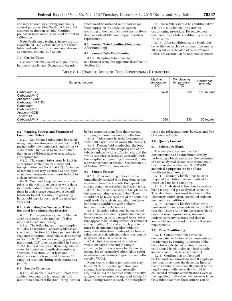
75337 Federal Register / Vol. 80, No. 230 / Tuesday, December 1, 2015 / Rules and Regulations
and may be used for auditing and quality control purposes. (See Section 9.5 for audit accuracy evaluation criteria.) Certified preloaded tubes may also be used for routine calibration.
Note: Proficiency testing schemes are also available for TD/GC/MS analysis of sorbent tubes preloaded with common analytes such as benzene, toluene, and xylene.
7.6 Carrier Gases Use inert, 99.999-percent or higher purity
helium as carrier gas. Oxygen and organic
filters must be installed in the carrier gas lines supplying the analytical system according to the manufacturer’s instructions. Keep records of filter and oxygen scrubber replacement.
8.0 Sorbent Tube Handling (Before and After Sampling)
8.1 Sample Tube Conditioning
8.1.1 Sampling tubes must be conditioned using the apparatus described in Section 6.2.
8.1.2 New tubes should be conditioned for 2 hours to supplement the vendor’s conditioning procedure. Recommended temperatures for tube conditioning are given in Table 8.1.
8.1.3 After conditioning, the blank must be verified on each new sorbent tube and on 10 percent of each batch of reconditioned tubes. See Section 9.0 for acceptance criteria.
TABLE 8.1—EXAMPLE SORBENT TUBE CONDITIONING PARAMETERS
Sampling sorbent Maximum
temperature (°C)
Conditioning temperature
(°C)
Carrier gas flow rate
Carbotrap® C ............................................................................................................................... >400 350 100 mL/min CarbopackTM C Anasorb® GCB2 CarbographTM 1 TD Carbotrap® CarbopackTM B Anasorb® GCB1 Tenax® TA CarbopackTM X ............................................................................................................................ 350 330 100 mL/min
8.2 Capping, Storage and Shipment of Conditioned Tubes
8.2.1 Conditioned tubes must be sealed using long-term storage caps (see Section 6.4) pushed fully down onto both ends of the PS sorbent tube, tightened by hand and then tighten an additional quarter turn using an appropriate tool.
8.2.2 The capped tubes must be kept in appropriate containers for storage and transportation (see Section 6.4.2). Containers of sorbent tubes may be stored and shipped at ambient temperature and must be kept in a clean environment.
8.2.3 You must keep batches of capped tubes in their shipping boxes or wrap them in uncoated aluminum foil before placing them in their storage container, especially before air freight, because the packaging helps hold caps in position if the tubes get very cold.
8.3 Calculating the Number of Tubes Required for a Monitoring Exercise
8.3.1 Follow guidance given in Method 325A to determine the number of tubes required for site monitoring.
8.3.2 The following additional samples will also be required: Laboratory blanks as specified in Section 9.1.2 (one per analytical sequence minimum), field blanks as specified in Section 9.3.2 (two per sampling period minimum), CCV tubes as specified in Section 10.9.4. (at least one per analysis sequence or every 24 hours), and duplicate samples as specified in Section 9.4 (at least one duplicate sample is required for every 10 sampling locations during each monitoring period).
8.4 Sample Collection
8.4.1 Allow the tubes to equilibrate with ambient temperature (approximately 30 minutes to 1 hour) at the monitoring location
before removing them from their storage/shipping container for sample collection.
8.4.2 Tubes must be used for sampling within 30 days of conditioning (Reference 4).
8.4.3 During field monitoring, the long- term storage cap at the sampling end of the tube is replaced with a diffusion cap and the whole assembly is arranged vertically, with the sampling end pointing downward, under a protective hood or shield—See Section 6.1 of Method 325A for more details.
8.5 Sample Storage
8.5.1 After sampling, tubes must be immediately resealed with long-term storage caps and placed back inside the type of storage container described in Section 6.4.2.
8.5.2 Exposed tubes may not be placed in the same container as clean tubes. They should not be taken back out of the container until ready for analysis and after they have had time to equilibrate with ambient temperature in the laboratory.
8.5.3 Sampled tubes must be inspected before analysis to identify problems such as loose or missing caps, damaged tubes, tubes that appear to be leaking sorbent or container contamination. Any and all such problems must be documented together with the unique identification number of the tube or tubes concerned. Affected tubes must not be analyzed but must be set aside.
8.5.4 Intact tubes must be analyzed within 30 days of the end of sample collection (within one week for limonene, carene, bis-chloromethyl ether, labile sulfur or nitrogen-containing compounds, and other reactive VOCs).
Note: Ensure ambient temperatures stay below 23 °C during transportation and storage. Refrigeration is not normally required unless the samples contain reactive compounds or cannot be analyzed within 30 days. If refrigeration is used, the atmosphere
inside the refrigerator must be clean and free of organic solvents.
9.0 Quality Control
9.1 Laboratory Blank
The analytical system must be demonstrated to be contaminant free by performing a blank analysis at the beginning of each analytical sequence to demonstrate that the secondary trap and TD/GC/MS analytical equipment are free of any significant interferents.
9.1.1 Laboratory blank tubes must be prepared from tubes that are identical to those used for field sampling.
9.1.2 Analysis of at least one laboratory blank is required per analytical sequence. The laboratory blank must be stored in the laboratory under clean, controlled ambient temperature conditions.
9.1.3 Laboratory blank/artifact levels must meet the requirements of Section 9.2.2 (see also Table 17.1). If the laboratory blank does not meet requirements, stop and perform corrective actions and then re- analyze laboratory blank to ensure it meets requirements.
9.2 Tube Conditioning
9.2.1 Conditioned tubes must be demonstrated to be free of contaminants and interference by running 10 percent of the blank tubes selected at random from each conditioned batch under standard sample analysis conditions (see Section 8.1).
9.2.2 Confirm that artifacts and background contamination are ≤ 0.2 ppbv or less than three times the detection limit of the procedure or less than 10 percent of the target compound(s) mass that would be collected if airborne concentrations were at the regulated limit value, whichever is larger. Only tubes that meet these criteria can be
VerDate Sep<11>2014 23:11 Nov 30, 2015 Jkt 238001 PO 00000 Frm 00161 Fmt 4701 Sfmt 4700 E:\FR\FM\01DER2.SGM 01DER2tkel
ley
on D
SK
3SP
TV
N1P
RO
D w
ith R
ULE
S2

75338 Federal Register / Vol. 80, No. 230 / Tuesday, December 1, 2015 / Rules and Regulations
used for field monitoring, field or laboratory blanks, or for system calibration.
9.2.3 If unacceptable levels of VOCs are observed in the tube blanks, then the processes of tube conditioning and checking the blanks must be repeated.
9.3 Field Blanks 9.3.1 Field blank tubes must be prepared
from tubes that are identical to those used for field sampling—i.e., they should be from the same batch, have a similar history, and be conditioned at the same time.
9.3.2 Field blanks must be shipped to the monitoring site with the sampling tubes and must be stored at the sampling location throughout the monitoring exercise. The field blanks must be installed under a protective hood/cover at the sampling location, but the long-term storage caps must remain in place throughout the monitoring period (see Method 325A). The field blanks are then shipped back to the laboratory in the same container as the sampled tubes. One field blank tube is required for every 10 sampled tubes on a monitoring exercise and no less than two field blanks should be collected, regardless of the size of the monitoring study.
9.3.3 Field blanks must contain no greater than one-third of the measured target analyte or compliance limit for field samples (see Table 17.1). If either field blank fails, flag all data that do not meet this criterion with a note that the associated results are estimated and likely to be biased high due to field blank background.
9.4 Duplicate Samples
Duplicate (co-located) samples collected must be analyzed and reported as part of method quality control. They are used to evaluate sampling and analysis precision. Relevant performance criteria are given in Section 9.9.
9.5 Method Performance Criteria
Unless otherwise noted, monitoring method performance specifications must be demonstrated for the target compounds using the procedures described in Addendum A to this method and the statistical approach presented in Method 301.
9.6 Method Detection Limit
Determine the method detection limit under the analytical conditions selected (see
Section 11.3) using the procedure in Section 15 of Method 301. The method detection limit is defined for each system by making seven replicate measurements of a concentration of the compound of interest within a factor of five of the detection limit. Compute the standard deviation for the seven replicate concentrations, and multiply this value by three. The results should demonstrate that the method is able to detect analytes such as benzene at concentrations as low as 50 ppt or 1/3rd (preferably 1/10th) of the lowest concentration of interest, whichever is larger.
Note: Determining the detection limit may be an iterative process as described in 40 CFR part 136, Appendix B.
9.7 Analytical Bias
Analytical bias must be demonstrated to be within ±30 percent using Equation 9.1. Analytical bias must be demonstrated during initial setup of this method and as part of the CCV carried out with every sequence of 10 samples or less (see Section 9.14). Calibration standard tubes (see Section 10.0) may be used for this purpose.
Where: Spiked Value = A known mass of VOCs
added to the tube. Measured Value = Mass determined from
analysis of the tube.
9.8 Analytical Precision
Demonstrate an analytical precision within ±20 percent using Equation 9.2. Analytical precision must be demonstrated during
initial setup of this method and at least once per year. Calibration standard tubes may be used (see Section 10.0) and data from CCV may also be applied for this purpose.
Where: A1 = A measurement value taken from one
spiked tube. A2 = A measurement value taken from a
second spiked tube. A = The average of A1 and A2.
9.9 Field Replicate Precision
Use Equation 9.3 to determine and report replicate precision for duplicate field samples (see Section 9.4). The level of agreement between duplicate
field samples is a measure of the precision achievable for the entire sampling and analysis procedure. Flag data sets for which the duplicate samples do not agree within 30 percent.
Where: F1 = A measurement value (mass) taken from
one of the two field replicate tubes used in sampling.
F2 = A measurement value (mass) taken from the second of two field replicate tubes used in sampling.
F = The average of F1 and F2.
9.10 Desorption Efficiency and Compound Recovery
The efficiency of the thermal desorption method must be determined.
9.10.1 Quantitative (>95 percent) compound recovery must be demonstrated by repeat analyses on a same standard tube.
9.10.2 Compound recovery through the TD system can also be demonstrated by comparing the calibration check sample response factor obtained from direct GC injection of liquid standards with that obtained from thermal desorption analysis response factor using the same column under identical conditions.
9.10.3 If the relative response factors obtained for one or more target compounds introduced to the column via thermal
desorption fail to meet the criteria in Section 9.10.1, you must adjust the TD parameters to meet the criteria and repeat the experiment. Once the thermal desorption conditions have been optimized, you must repeat this test each time the analytical system is recalibrated to demonstrate continued method performance.
9.11 Audit Samples
Certified reference standard samples must be used to audit this procedure (if available). Accuracy within 30 percent must be
VerDate Sep<11>2014 23:11 Nov 30, 2015 Jkt 238001 PO 00000 Frm 00162 Fmt 4701 Sfmt 4700 E:\FR\FM\01DER2.SGM 01DER2 ER
01D
E15
.032
</G
PH
>E
R01
DE
15.0
33<
/GP
H>
ER
01D
E15
.034
</G
PH
>
tkel
ley
on D
SK
3SP
TV
N1P
RO
D w
ith R
ULE
S2
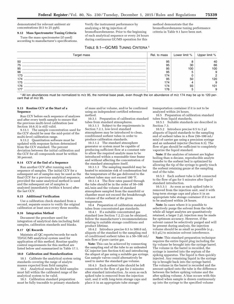
75339 Federal Register / Vol. 80, No. 230 / Tuesday, December 1, 2015 / Rules and Regulations
demonstrated for relevant ambient air concentrations (0.5 to 25 ppb).
9.12 Mass Spectrometer Tuning Criteria Tune the mass spectrometer (if used)
according to manufacturer’s specifications.
Verify the instrument performance by analyzing a 50 hg injection of bromofluorobenzene. Prior to the beginning of each analytical sequence or every 24 hours during continuous GC/MS operation for this
method demonstrate that the bromofluorobenzene tuning performance criteria in Table 9.1 have been met.
TABLE 9.1—GC/MS TUNING CRITERIA 1
Target mass Rel. to mass Lower limit % Upper limit %
50 ................................................................................................................................................. 95 8 40 75 ................................................................................................................................................. 95 30 66 95 ................................................................................................................................................. 95 100 100 96 ................................................................................................................................................. 95 5 9 173 ............................................................................................................................................... 174 0 2 174 ............................................................................................................................................... 95 50 120 175 ............................................................................................................................................... 174 4 9 176 ............................................................................................................................................... 174 93 101 177 ............................................................................................................................................... 176 5 9
1 All ion abundances must be normalized to m/z 95, the nominal base peak, even though the ion abundance of m/z 174 may be up to 120 per-cent that of m/z 95.
9.13 Routine CCV at the Start of a Sequence
Run CCV before each sequence of analyses and after every tenth sample to ensure that the previous multi-level calibration (see Section 10.6.3) is still valid.
9.13.1 The sample concentration used for the CCV should be near the mid-point of the multi-level calibration range.
9.13.2 Quantitation software must be updated with response factors determined from the CCV standard. The percent deviation between the initial calibration and the CCV for all compounds must be within 30 percent.
9.14 CCV at the End of a Sequence Run another CCV after running each
sequence of samples. The initial CCV for a subsequent set of samples may be used as the final CCV for a previous analytical sequence, provided the same analytical method is used and the subsequent set of samples is analyzed immediately (within 4 hours) after the last CCV.
9.15 Additional Verification Use a calibration check standard from a
second, separate source to verify the original calibration at least once every three months.
9.16 Integration Method
Document the procedure used for integration of analytical data including field samples, calibration standards and blanks.
9.17 QC Records
Maintain all QC reports/records for each TD/GC/MS analytical system used for application of this method. Routine quality control requirements for this method are listed below and summarized in Table 17.1.
10.0 Calibration and Standardization
10.1 Calibrate the analytical system using standards covering the range of analyte masses expected from field samples.
10.2 Analytical results for field samples must fall within the calibrated range of the analytical system to be valid.
10.3 Calibration standard preparation must be fully traceable to primary standards
of mass and/or volume, and/or be confirmed using an independent certified reference method.
10.3.1 Preparation of calibration standard tubes from standard atmospheres.
10.3.1.1 Subject to the requirements in Section 7.2.1, low-level standard atmospheres may be introduced to clean, conditioned sorbent tubes in order to produce calibration standards.
10.3.1.2 The standard atmosphere generator or system must be capable of producing sufficient flow at a constant rate to allow the required analyte mass to be introduced within a reasonable time frame and without affecting the concentration of the standard atmosphere itself.
10.3.1.3 The sampling manifold may be heated to minimize risk of condensation but the temperature of the gas delivered to the sorbent tubes may not exceed 100 °F.
10.3.1.4 The flow rates passed through the tube should be in the order of 50–100 mL/min and the volume of standard atmosphere sampled from the manifold or chamber must not exceed the breakthrough volume of the sorbent at the given temperature.
10.4 Preparation of calibration standard tubes from concentrated gas standards.
10.4.1 If a suitable concentrated gas standard (see Section 7.2.2) can be obtained, follow the manufacturer’s recommendations relating to suitable storage conditions and product lifetime.
10.4.2 Introduce precise 0.5 to 500.0 mL aliquots of the standard to the sampling end of conditioned sorbent tubes in a 50–100 mL/ min flow of pure carrier gas.
Note: This can be achieved by connecting the sampling end of the tube to an unheated GC injector (see Section 6.6) and introducing the aliquot of gas using a suitable gas syringe. Gas sample valves could alternatively be used to meter the standard gas volume.
10.4.3 Each sorbent tube should be left connected to the flow of gas for 2 minutes after standard introduction. As soon as each spiked tube is removed from the injection unit, seal it with long-term storage caps and place it in an appropriate tube storage/
transportation container if it is not to be analyzed within 24 hours.
10.5 Preparation of calibration standard tubes from liquid standards.
10.5.1 Suitable standards are described in Section 7.3.
10.5.2 Introduce precise 0.5 to 2 ml aliquots of liquid standards to the sampling end of sorbent tubes in a flow (50–100 mL/ min) of carrier gas using a precision syringe and an unheated injector (Section 6.5). The flow of gas should be sufficient to completely vaporize the liquid standard.
Note: If the analytes of interest are higher boiling than n-decane, reproducible analyte transfer to the sorbent bed is optimized by allowing the tip of the syringe to gently touch the sorbent retaining gauze at the sampling end of the tube.
10.5.3 Each sorbent tube is left connected to the flow of gas for 5 minutes after liquid standard introduction.
10.5.3.1 As soon as each spiked tube is removed from the injection unit, seal it with long-term storage caps and place it in an appropriate tube storage container if it is not to be analyzed within 24 hours.
Note: In cases where it is possible to selectively purge the solvent from the tube while all target analytes are quantitatively retained, a larger 2 mL injection may be made for optimum accuracy. However, if the solvent cannot be selectively purged and will be present during analysis, the injection volume should be as small as possible (e.g., 0.5 mL) to minimize solvent interference.
Note: This standard preparation technique requires the entire liquid plug including the tip volume be brought into the syringe barrel. The volume in the barrel is recorded, the syringe is inserted into the septum of the spiking apparatus. The liquid is then quickly injected. Any remaining liquid in the syringe tip is brought back into the syringe barrel. The volume in the barrel is recorded and the amount spiked onto the tube is the difference between the before spiking volume and the after spiking volume. A bias occurs with this method when sample is drawn continuously up into the syringe to the specified volume
VerDate Sep<11>2014 23:11 Nov 30, 2015 Jkt 238001 PO 00000 Frm 00163 Fmt 4701 Sfmt 4700 E:\FR\FM\01DER2.SGM 01DER2tkel
ley
on D
SK
3SP
TV
N1P
RO
D w
ith R
ULE
S2
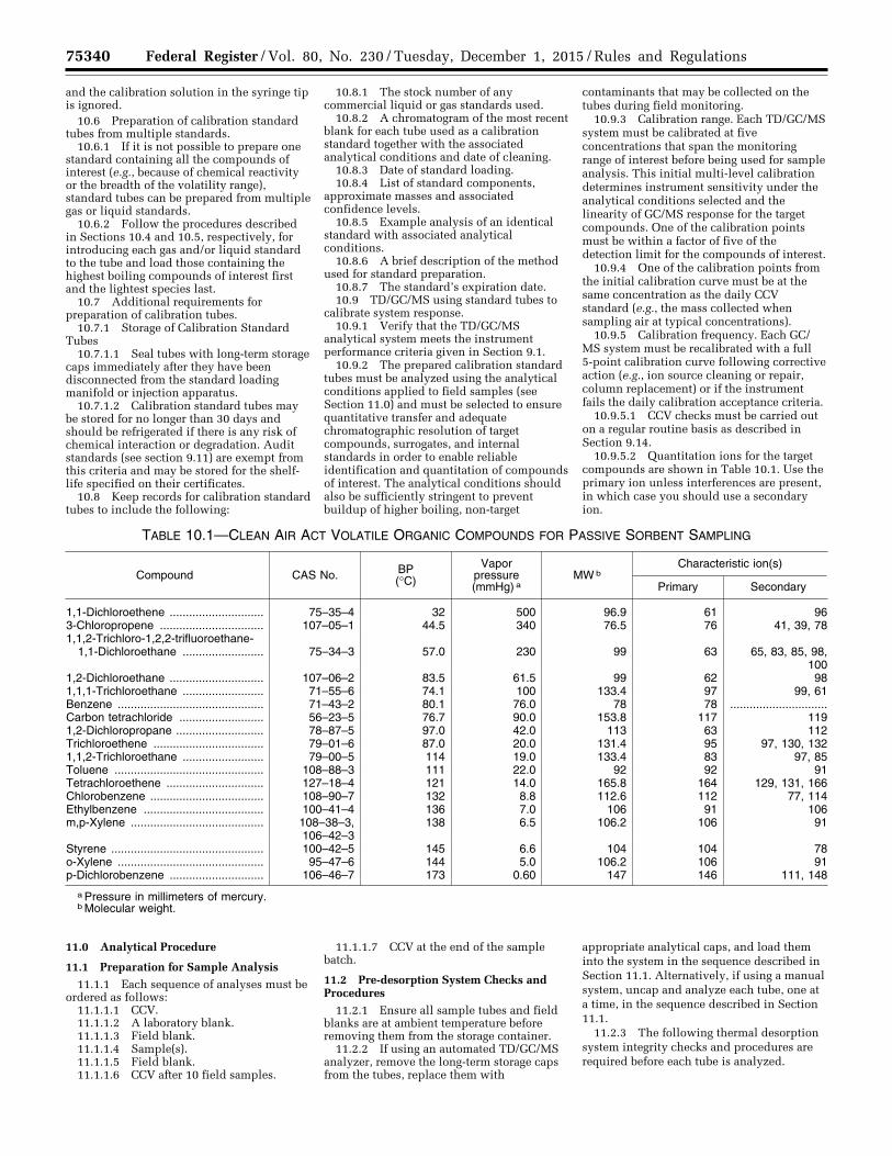
75340 Federal Register / Vol. 80, No. 230 / Tuesday, December 1, 2015 / Rules and Regulations
and the calibration solution in the syringe tip is ignored.
10.6 Preparation of calibration standard tubes from multiple standards.
10.6.1 If it is not possible to prepare one standard containing all the compounds of interest (e.g., because of chemical reactivity or the breadth of the volatility range), standard tubes can be prepared from multiple gas or liquid standards.
10.6.2 Follow the procedures described in Sections 10.4 and 10.5, respectively, for introducing each gas and/or liquid standard to the tube and load those containing the highest boiling compounds of interest first and the lightest species last.
10.7 Additional requirements for preparation of calibration tubes.
10.7.1 Storage of Calibration Standard Tubes
10.7.1.1 Seal tubes with long-term storage caps immediately after they have been disconnected from the standard loading manifold or injection apparatus.
10.7.1.2 Calibration standard tubes may be stored for no longer than 30 days and should be refrigerated if there is any risk of chemical interaction or degradation. Audit standards (see section 9.11) are exempt from this criteria and may be stored for the shelf- life specified on their certificates.
10.8 Keep records for calibration standard tubes to include the following:
10.8.1 The stock number of any commercial liquid or gas standards used.
10.8.2 A chromatogram of the most recent blank for each tube used as a calibration standard together with the associated analytical conditions and date of cleaning.
10.8.3 Date of standard loading. 10.8.4 List of standard components,
approximate masses and associated confidence levels.
10.8.5 Example analysis of an identical standard with associated analytical conditions.
10.8.6 A brief description of the method used for standard preparation.
10.8.7 The standard’s expiration date. 10.9 TD/GC/MS using standard tubes to
calibrate system response. 10.9.1 Verify that the TD/GC/MS
analytical system meets the instrument performance criteria given in Section 9.1.
10.9.2 The prepared calibration standard tubes must be analyzed using the analytical conditions applied to field samples (see Section 11.0) and must be selected to ensure quantitative transfer and adequate chromatographic resolution of target compounds, surrogates, and internal standards in order to enable reliable identification and quantitation of compounds of interest. The analytical conditions should also be sufficiently stringent to prevent buildup of higher boiling, non-target
contaminants that may be collected on the tubes during field monitoring.
10.9.3 Calibration range. Each TD/GC/MS system must be calibrated at five concentrations that span the monitoring range of interest before being used for sample analysis. This initial multi-level calibration determines instrument sensitivity under the analytical conditions selected and the linearity of GC/MS response for the target compounds. One of the calibration points must be within a factor of five of the detection limit for the compounds of interest.
10.9.4 One of the calibration points from the initial calibration curve must be at the same concentration as the daily CCV standard (e.g., the mass collected when sampling air at typical concentrations).
10.9.5 Calibration frequency. Each GC/MS system must be recalibrated with a full 5-point calibration curve following corrective action (e.g., ion source cleaning or repair, column replacement) or if the instrument fails the daily calibration acceptance criteria.
10.9.5.1 CCV checks must be carried out on a regular routine basis as described in Section 9.14.
10.9.5.2 Quantitation ions for the target compounds are shown in Table 10.1. Use the primary ion unless interferences are present, in which case you should use a secondary ion.
TABLE 10.1—CLEAN AIR ACT VOLATILE ORGANIC COMPOUNDS FOR PASSIVE SORBENT SAMPLING
Compound CAS No. BP (°C)
Vapor pressure (mmHg) a
MW b Characteristic ion(s)
Primary Secondary
1,1-Dichloroethene ............................. 75–35–4 32 500 96.9 61 96 3-Chloropropene ................................ 107–05–1 44.5 340 76.5 76 41, 39, 78 1,1,2-Trichloro-1,2,2-trifluoroethane-
1,1-Dichloroethane ......................... 75–34–3 57.0 230 99 63 65, 83, 85, 98, 100
1,2-Dichloroethane ............................. 107–06–2 83.5 61.5 99 62 98 1,1,1-Trichloroethane ......................... 71–55–6 74.1 100 133.4 97 99, 61 Benzene ............................................. 71–43–2 80.1 76.0 78 78 ..............................Carbon tetrachloride .......................... 56–23–5 76.7 90.0 153.8 117 119 1,2-Dichloropropane ........................... 78–87–5 97.0 42.0 113 63 112 Trichloroethene .................................. 79–01–6 87.0 20.0 131.4 95 97, 130, 132 1,1,2-Trichloroethane ......................... 79–00–5 114 19.0 133.4 83 97, 85 Toluene .............................................. 108–88–3 111 22.0 92 92 91 Tetrachloroethene .............................. 127–18–4 121 14.0 165.8 164 129, 131, 166 Chlorobenzene ................................... 108–90–7 132 8.8 112.6 112 77, 114 Ethylbenzene ..................................... 100–41–4 136 7.0 106 91 106 m,p-Xylene ......................................... 108–38–3,
106–42–3 138 6.5 106.2 106 91
Styrene ............................................... 100–42–5 145 6.6 104 104 78 o-Xylene ............................................. 95–47–6 144 5.0 106.2 106 91 p-Dichlorobenzene ............................. 106–46–7 173 0.60 147 146 111, 148
a Pressure in millimeters of mercury. b Molecular weight.
11.0 Analytical Procedure
11.1 Preparation for Sample Analysis 11.1.1 Each sequence of analyses must be
ordered as follows: 11.1.1.1 CCV. 11.1.1.2 A laboratory blank. 11.1.1.3 Field blank. 11.1.1.4 Sample(s). 11.1.1.5 Field blank. 11.1.1.6 CCV after 10 field samples.
11.1.1.7 CCV at the end of the sample batch.
11.2 Pre-desorption System Checks and Procedures
11.2.1 Ensure all sample tubes and field blanks are at ambient temperature before removing them from the storage container.
11.2.2 If using an automated TD/GC/MS analyzer, remove the long-term storage caps from the tubes, replace them with
appropriate analytical caps, and load them into the system in the sequence described in Section 11.1. Alternatively, if using a manual system, uncap and analyze each tube, one at a time, in the sequence described in Section 11.1.
11.2.3 The following thermal desorption system integrity checks and procedures are required before each tube is analyzed.
VerDate Sep<11>2014 23:11 Nov 30, 2015 Jkt 238001 PO 00000 Frm 00164 Fmt 4701 Sfmt 4700 E:\FR\FM\01DER2.SGM 01DER2tkel
ley
on D
SK
3SP
TV
N1P
RO
D w
ith R
ULE
S2
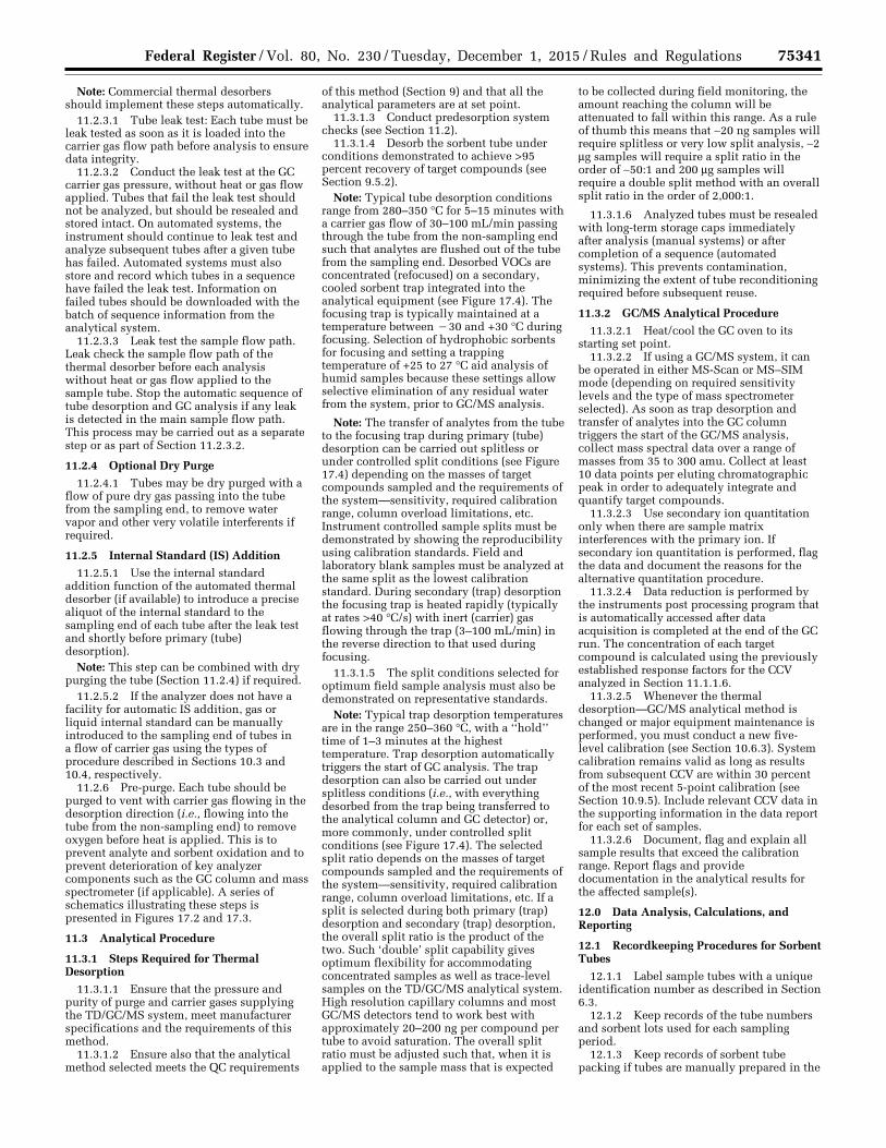
75341 Federal Register / Vol. 80, No. 230 / Tuesday, December 1, 2015 / Rules and Regulations
Note: Commercial thermal desorbers should implement these steps automatically.
11.2.3.1 Tube leak test: Each tube must be leak tested as soon as it is loaded into the carrier gas flow path before analysis to ensure data integrity.
11.2.3.2 Conduct the leak test at the GC carrier gas pressure, without heat or gas flow applied. Tubes that fail the leak test should not be analyzed, but should be resealed and stored intact. On automated systems, the instrument should continue to leak test and analyze subsequent tubes after a given tube has failed. Automated systems must also store and record which tubes in a sequence have failed the leak test. Information on failed tubes should be downloaded with the batch of sequence information from the analytical system.
11.2.3.3 Leak test the sample flow path. Leak check the sample flow path of the thermal desorber before each analysis without heat or gas flow applied to the sample tube. Stop the automatic sequence of tube desorption and GC analysis if any leak is detected in the main sample flow path. This process may be carried out as a separate step or as part of Section 11.2.3.2.
11.2.4 Optional Dry Purge
11.2.4.1 Tubes may be dry purged with a flow of pure dry gas passing into the tube from the sampling end, to remove water vapor and other very volatile interferents if required.
11.2.5 Internal Standard (IS) Addition
11.2.5.1 Use the internal standard addition function of the automated thermal desorber (if available) to introduce a precise aliquot of the internal standard to the sampling end of each tube after the leak test and shortly before primary (tube) desorption).
Note: This step can be combined with dry purging the tube (Section 11.2.4) if required.
11.2.5.2 If the analyzer does not have a facility for automatic IS addition, gas or liquid internal standard can be manually introduced to the sampling end of tubes in a flow of carrier gas using the types of procedure described in Sections 10.3 and 10.4, respectively.
11.2.6 Pre-purge. Each tube should be purged to vent with carrier gas flowing in the desorption direction (i.e., flowing into the tube from the non-sampling end) to remove oxygen before heat is applied. This is to prevent analyte and sorbent oxidation and to prevent deterioration of key analyzer components such as the GC column and mass spectrometer (if applicable). A series of schematics illustrating these steps is presented in Figures 17.2 and 17.3.
11.3 Analytical Procedure
11.3.1 Steps Required for Thermal Desorption
11.3.1.1 Ensure that the pressure and purity of purge and carrier gases supplying the TD/GC/MS system, meet manufacturer specifications and the requirements of this method.
11.3.1.2 Ensure also that the analytical method selected meets the QC requirements
of this method (Section 9) and that all the analytical parameters are at set point.
11.3.1.3 Conduct predesorption system checks (see Section 11.2).
11.3.1.4 Desorb the sorbent tube under conditions demonstrated to achieve >95 percent recovery of target compounds (see Section 9.5.2).
Note: Typical tube desorption conditions range from 280–350 °C for 5–15 minutes with a carrier gas flow of 30–100 mL/min passing through the tube from the non-sampling end such that analytes are flushed out of the tube from the sampling end. Desorbed VOCs are concentrated (refocused) on a secondary, cooled sorbent trap integrated into the analytical equipment (see Figure 17.4). The focusing trap is typically maintained at a temperature between ¥30 and +30 °C during focusing. Selection of hydrophobic sorbents for focusing and setting a trapping temperature of +25 to 27 °C aid analysis of humid samples because these settings allow selective elimination of any residual water from the system, prior to GC/MS analysis.
Note: The transfer of analytes from the tube to the focusing trap during primary (tube) desorption can be carried out splitless or under controlled split conditions (see Figure 17.4) depending on the masses of target compounds sampled and the requirements of the system—sensitivity, required calibration range, column overload limitations, etc. Instrument controlled sample splits must be demonstrated by showing the reproducibility using calibration standards. Field and laboratory blank samples must be analyzed at the same split as the lowest calibration standard. During secondary (trap) desorption the focusing trap is heated rapidly (typically at rates >40 °C/s) with inert (carrier) gas flowing through the trap (3–100 mL/min) in the reverse direction to that used during focusing.
11.3.1.5 The split conditions selected for optimum field sample analysis must also be demonstrated on representative standards.
Note: Typical trap desorption temperatures are in the range 250–360 °C, with a ‘‘hold’’ time of 1–3 minutes at the highest temperature. Trap desorption automatically triggers the start of GC analysis. The trap desorption can also be carried out under splitless conditions (i.e., with everything desorbed from the trap being transferred to the analytical column and GC detector) or, more commonly, under controlled split conditions (see Figure 17.4). The selected split ratio depends on the masses of target compounds sampled and the requirements of the system—sensitivity, required calibration range, column overload limitations, etc. If a split is selected during both primary (trap) desorption and secondary (trap) desorption, the overall split ratio is the product of the two. Such ‘double’ split capability gives optimum flexibility for accommodating concentrated samples as well as trace-level samples on the TD/GC/MS analytical system. High resolution capillary columns and most GC/MS detectors tend to work best with approximately 20–200 ng per compound per tube to avoid saturation. The overall split ratio must be adjusted such that, when it is applied to the sample mass that is expected
to be collected during field monitoring, the amount reaching the column will be attenuated to fall within this range. As a rule of thumb this means that ∼20 ng samples will require splitless or very low split analysis, ∼2 mg samples will require a split ratio in the order of ∼50:1 and 200 mg samples will require a double split method with an overall split ratio in the order of 2,000:1.
11.3.1.6 Analyzed tubes must be resealed with long-term storage caps immediately after analysis (manual systems) or after completion of a sequence (automated systems). This prevents contamination, minimizing the extent of tube reconditioning required before subsequent reuse.
11.3.2 GC/MS Analytical Procedure
11.3.2.1 Heat/cool the GC oven to its starting set point.
11.3.2.2 If using a GC/MS system, it can be operated in either MS-Scan or MS–SIM mode (depending on required sensitivity levels and the type of mass spectrometer selected). As soon as trap desorption and transfer of analytes into the GC column triggers the start of the GC/MS analysis, collect mass spectral data over a range of masses from 35 to 300 amu. Collect at least 10 data points per eluting chromatographic peak in order to adequately integrate and quantify target compounds.
11.3.2.3 Use secondary ion quantitation only when there are sample matrix interferences with the primary ion. If secondary ion quantitation is performed, flag the data and document the reasons for the alternative quantitation procedure.
11.3.2.4 Data reduction is performed by the instruments post processing program that is automatically accessed after data acquisition is completed at the end of the GC run. The concentration of each target compound is calculated using the previously established response factors for the CCV analyzed in Section 11.1.1.6.
11.3.2.5 Whenever the thermal desorption—GC/MS analytical method is changed or major equipment maintenance is performed, you must conduct a new five- level calibration (see Section 10.6.3). System calibration remains valid as long as results from subsequent CCV are within 30 percent of the most recent 5-point calibration (see Section 10.9.5). Include relevant CCV data in the supporting information in the data report for each set of samples.
11.3.2.6 Document, flag and explain all sample results that exceed the calibration range. Report flags and provide documentation in the analytical results for the affected sample(s).
12.0 Data Analysis, Calculations, and Reporting
12.1 Recordkeeping Procedures for Sorbent Tubes
12.1.1 Label sample tubes with a unique identification number as described in Section 6.3.
12.1.2 Keep records of the tube numbers and sorbent lots used for each sampling period.
12.1.3 Keep records of sorbent tube packing if tubes are manually prepared in the
VerDate Sep<11>2014 23:11 Nov 30, 2015 Jkt 238001 PO 00000 Frm 00165 Fmt 4701 Sfmt 4700 E:\FR\FM\01DER2.SGM 01DER2tkel
ley
on D
SK
3SP
TV
N1P
RO
D w
ith R
ULE
S2
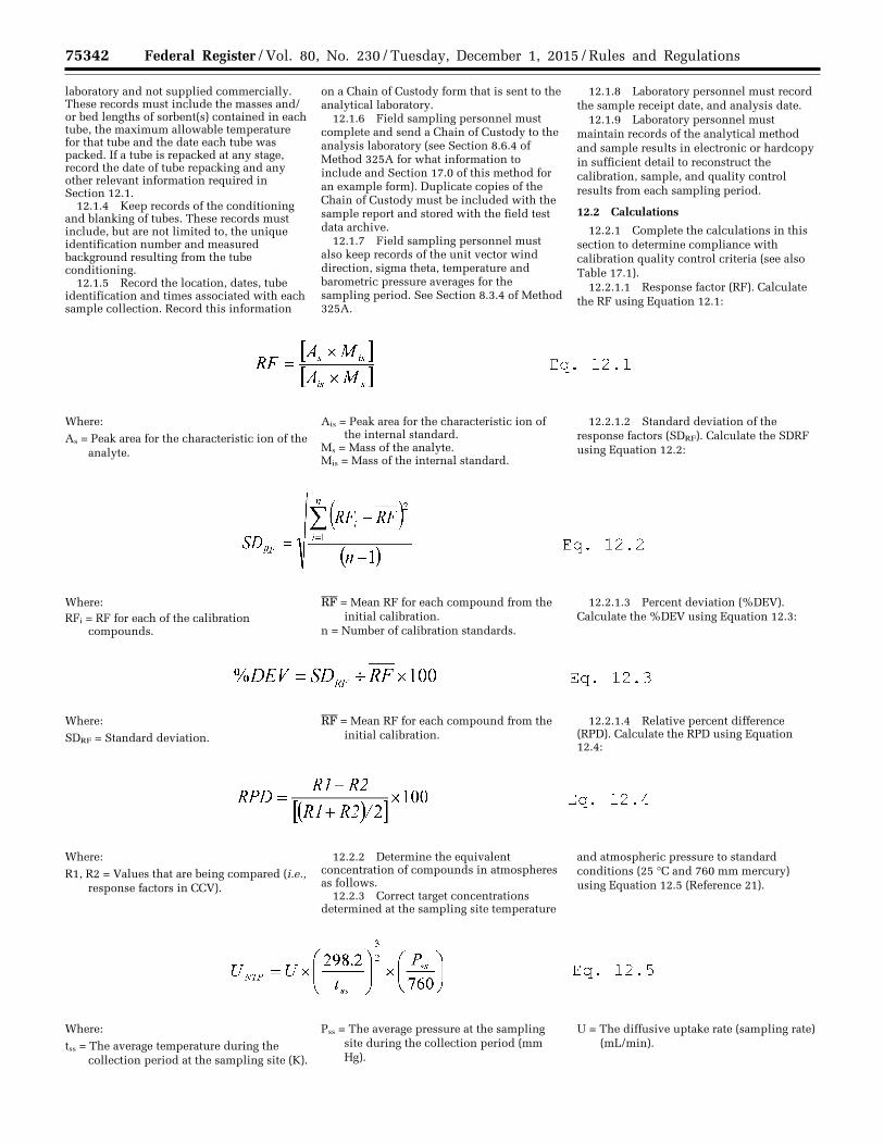
75342 Federal Register / Vol. 80, No. 230 / Tuesday, December 1, 2015 / Rules and Regulations
laboratory and not supplied commercially. These records must include the masses and/ or bed lengths of sorbent(s) contained in each tube, the maximum allowable temperature for that tube and the date each tube was packed. If a tube is repacked at any stage, record the date of tube repacking and any other relevant information required in Section 12.1.
12.1.4 Keep records of the conditioning and blanking of tubes. These records must include, but are not limited to, the unique identification number and measured background resulting from the tube conditioning.
12.1.5 Record the location, dates, tube identification and times associated with each sample collection. Record this information
on a Chain of Custody form that is sent to the analytical laboratory.
12.1.6 Field sampling personnel must complete and send a Chain of Custody to the analysis laboratory (see Section 8.6.4 of Method 325A for what information to include and Section 17.0 of this method for an example form). Duplicate copies of the Chain of Custody must be included with the sample report and stored with the field test data archive.
12.1.7 Field sampling personnel must also keep records of the unit vector wind direction, sigma theta, temperature and barometric pressure averages for the sampling period. See Section 8.3.4 of Method 325A.
12.1.8 Laboratory personnel must record the sample receipt date, and analysis date.
12.1.9 Laboratory personnel must maintain records of the analytical method and sample results in electronic or hardcopy in sufficient detail to reconstruct the calibration, sample, and quality control results from each sampling period.
12.2 Calculations
12.2.1 Complete the calculations in this section to determine compliance with calibration quality control criteria (see also Table 17.1).
12.2.1.1 Response factor (RF). Calculate the RF using Equation 12.1:
Where:
As = Peak area for the characteristic ion of the analyte.
Ais = Peak area for the characteristic ion of the internal standard.
Ms = Mass of the analyte. Mis = Mass of the internal standard.
12.2.1.2 Standard deviation of the response factors (SDRF). Calculate the SDRF using Equation 12.2:
Where: RFi = RF for each of the calibration
compounds.
RF = Mean RF for each compound from the initial calibration.
n = Number of calibration standards.
12.2.1.3 Percent deviation (%DEV). Calculate the %DEV using Equation 12.3:
Where:
SDRF = Standard deviation.
RF = Mean RF for each compound from the initial calibration.
12.2.1.4 Relative percent difference (RPD). Calculate the RPD using Equation 12.4:
Where:
R1, R2 = Values that are being compared (i.e., response factors in CCV).
12.2.2 Determine the equivalent concentration of compounds in atmospheres as follows.
12.2.3 Correct target concentrations determined at the sampling site temperature
and atmospheric pressure to standard conditions (25 °C and 760 mm mercury) using Equation 12.5 (Reference 21).
Where:
tss = The average temperature during the collection period at the sampling site (K).
Pss = The average pressure at the sampling site during the collection period (mm Hg).
U = The diffusive uptake rate (sampling rate) (mL/min).
VerDate Sep<11>2014 23:11 Nov 30, 2015 Jkt 238001 PO 00000 Frm 00166 Fmt 4701 Sfmt 4700 E:\FR\FM\01DER2.SGM 01DER2 ER
01D
E15
.035
</G
PH
>E
R01
DE
15.0
36<
/GP
H>
ER
01D
E15
.037
</G
PH
>E
R01
DE
15.0
38<
/GP
H>
ER
01D
E15
.039
</G
PH
>
tkel
ley
on D
SK
3SP
TV
N1P
RO
D w
ith R
ULE
S2
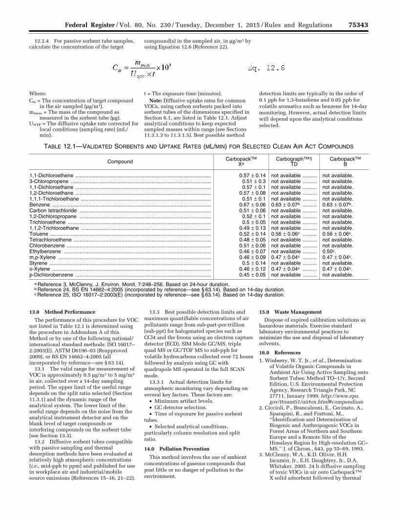
75343 Federal Register / Vol. 80, No. 230 / Tuesday, December 1, 2015 / Rules and Regulations
12.2.4 For passive sorbent tube samples, calculate the concentration of the target
compound(s) in the sampled air, in mg/m3 by using Equation 12.6 (Reference 22).
Where: Cm = The concentration of target compound
in the air sampled (mg/m3). mmeas = The mass of the compound as
measured in the sorbent tube (mg). UNTP = The diffusive uptake rate corrected for
local conditions (sampling rate) (mL/min).
t = The exposure time (minutes). Note: Diffusive uptake rates for common
VOCs, using carbon sorbents packed into sorbent tubes of the dimensions specified in Section 6.1, are listed in Table 12.1. Adjust analytical conditions to keep expected sampled masses within range (see Sections 11.3.1.3 to 11.3.1.5). Best possible method
detection limits are typically in the order of 0.1 ppb for 1,3-butadiene and 0.05 ppb for volatile aromatics such as benzene for 14-day monitoring. However, actual detection limits will depend upon the analytical conditions selected.
TABLE 12.1—VALIDATED SORBENTS AND UPTAKE RATES (ML/MIN) FOR SELECTED CLEAN AIR ACT COMPOUNDS
Compound CarbopackTM Xa
CarbographTM1 TD
CarbopackTM B
1,1-Dichloroethene .............................................................................................. 0.57 ± 0.14 not available .......... not available. 3-Chloropropene ................................................................................................. 0.51 ± 0.3 not available .......... not available. 1,1-Dichloroethane .............................................................................................. 0.57 ± 0.1 not available .......... not available. 1,2-Dichloroethane .............................................................................................. 0.57 ± 0.08 not available .......... not available. 1,1,1-Trichloroethane .......................................................................................... 0.51 ± 0.1 not available .......... not available. Benzene .............................................................................................................. 0.67 ± 0.06 0.63 ± 0.07b .......... 0.63 ± 0.07b. Carbon tetrachloride ........................................................................................... 0.51 ± 0.06 not available .......... not available. 1,2-Dichloropropane ........................................................................................... 0.52 ± 0.1 not available .......... not available. Trichloroethene ................................................................................................... 0.5 ± 0.05 not available .......... not available. 1,1,2-Trichloroethane .......................................................................................... 0.49 ± 0.13 not available .......... not available. Toluene ............................................................................................................... 0.52 ± 0.14 0.56 ± 0.06c .......... 0.56 ± 0.06c. Tetrachloroethene ............................................................................................... 0.48 ± 0.05 not available .......... not available. Chlorobenzene .................................................................................................... 0.51 ± 0.06 not available .......... not available. Ethylbenzene ...................................................................................................... 0.46 ± 0.07 not available .......... 0.50c. m,p-Xylene .......................................................................................................... 0.46 ± 0.09 0.47 ± 0.04c .......... 0.47 ± 0.04c. Styrene ................................................................................................................ 0.5 ± 0.14 not available .......... not available. o-Xylene .............................................................................................................. 0.46 ± 0.12 0.47 ± 0.04c .......... 0.47 ± 0.04c. p-Dichlorobenzene .............................................................................................. 0.45 ± 0.05 not available .......... not available.
a Reference 3, McClenny, J. Environ. Monit. 7:248–256. Based on 24-hour duration. b Reference 24, BS EN 14662–4:2005 (incorporated by reference—see § 63.14). Based on 14-day duration. c Reference 25, ISO 16017–2:2003(E) (incorporated by reference—see § 63.14). Based on 14-day duration.
13.0 Method Performance
The performance of this procedure for VOC not listed in Table 12.1 is determined using the procedure in Addendum A of this Method or by one of the following national/ international standard methods: ISO 16017– 2:2003(E), ASTM D6196–03 (Reapproved 2009), or BS EN 14662–4:2005 (all incorporated by reference—see § 63.14).
13.1 The valid range for measurement of VOC is approximately 0.5 mg/m3 to 5 mg/m3 in air, collected over a 14-day sampling period. The upper limit of the useful range depends on the split ratio selected (Section 11.3.1) and the dynamic range of the analytical system. The lower limit of the useful range depends on the noise from the analytical instrument detector and on the blank level of target compounds or interfering compounds on the sorbent tube (see Section 13.3).
13.2 Diffusive sorbent tubes compatible with passive sampling and thermal desorption methods have been evaluated at relatively high atmospheric concentrations (i.e., mid-ppb to ppm) and published for use in workplace air and industrial/mobile source emissions (References 15–16, 21–22).
13.3 Best possible detection limits and maximum quantifiable concentrations of air pollutants range from sub-part-per-trillion (sub-ppt) for halogenated species such as CCl4 and the freons using an electron capture detector (ECD), SIM Mode GC/MS, triple quad MS or GC/TOF MS to sub-ppb for volatile hydrocarbons collected over 72 hours followed by analysis using GC with quadrupole MS operated in the full SCAN mode.
13.3.1 Actual detection limits for atmospheric monitoring vary depending on several key factors. These factors are:
• Minimum artifact levels. • GC detector selection. • Time of exposure for passive sorbent
tubes. • Selected analytical conditions,
particularly column resolution and split ratio.
14.0 Pollution Prevention
This method involves the use of ambient concentrations of gaseous compounds that post little or no danger of pollution to the environment.
15.0 Waste Management
Dispose of expired calibration solutions as hazardous materials. Exercise standard laboratory environmental practices to minimize the use and disposal of laboratory solvents.
16.0 References
1. Winberry, W. T. Jr., et al., Determination of Volatile Organic Compounds in Ambient Air Using Active Sampling onto Sorbent Tubes: Method TO–17r, Second Edition, U.S. Environmental Protection Agency, Research Triangle Park, NC 27711, January 1999. http://www.epa.gov/ttnamti1/airtox.html#compendium
2. Ciccioli, P., Brancaleoni, E., Cecinato, A., Sparapini, R., and Frattoni, M., ‘‘Identification and Determination of Biogenic and Anthropogenic VOCs in Forest Areas of Northern and Southern Europe and a Remote Site of the Himalaya Region by High-resolution GC– MS,’’ J. of Chrom., 643, pp 55–69, 1993.
3. McClenny, W.A., K.D. Oliver, H.H. Jacumin, Jr., E.H. Daughtrey, Jr., D.A. Whitaker. 2005. 24 h diffusive sampling of toxic VOCs in air onto CarbopackTM X solid adsorbent followed by thermal
VerDate Sep<11>2014 23:11 Nov 30, 2015 Jkt 238001 PO 00000 Frm 00167 Fmt 4701 Sfmt 4700 E:\FR\FM\01DER2.SGM 01DER2 ER
01D
E15
.040
</G
PH
>
tkel
ley
on D
SK
3SP
TV
N1P
RO
D w
ith R
ULE
S2
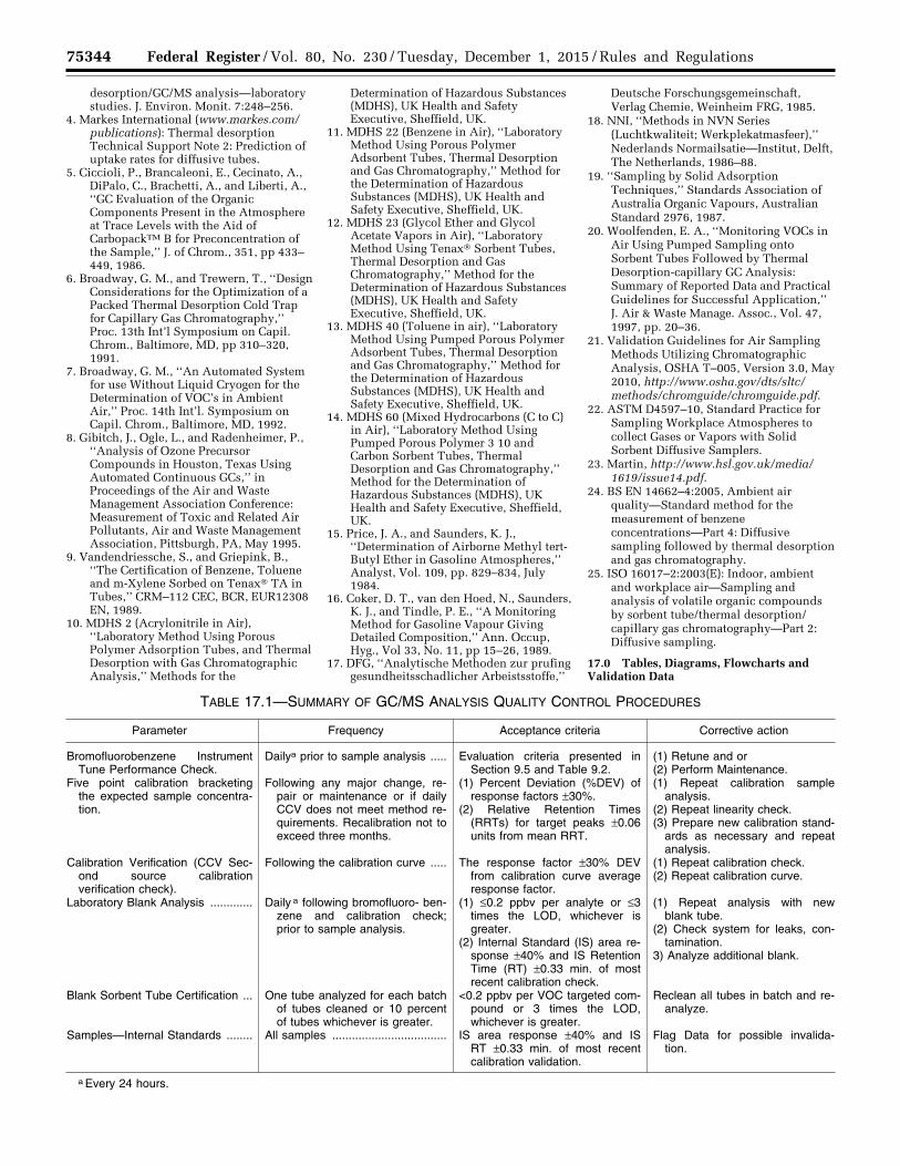
75344 Federal Register / Vol. 80, No. 230 / Tuesday, December 1, 2015 / Rules and Regulations
desorption/GC/MS analysis—laboratory studies. J. Environ. Monit. 7:248–256.
4. Markes International (www.markes.com/publications): Thermal desorption Technical Support Note 2: Prediction of uptake rates for diffusive tubes.
5. Ciccioli, P., Brancaleoni, E., Cecinato, A., DiPalo, C., Brachetti, A., and Liberti, A., ‘‘GC Evaluation of the Organic Components Present in the Atmosphere at Trace Levels with the Aid of CarbopackTM B for Preconcentration of the Sample,’’ J. of Chrom., 351, pp 433– 449, 1986.
6. Broadway, G. M., and Trewern, T., ‘‘Design Considerations for the Optimization of a Packed Thermal Desorption Cold Trap for Capillary Gas Chromatography,’’ Proc. 13th Int’l Symposium on Capil. Chrom., Baltimore, MD, pp 310–320, 1991.
7. Broadway, G. M., ‘‘An Automated System for use Without Liquid Cryogen for the Determination of VOC’s in Ambient Air,’’ Proc. 14th Int’l. Symposium on Capil. Chrom., Baltimore, MD, 1992.
8. Gibitch, J., Ogle, L., and Radenheimer, P., ‘‘Analysis of Ozone Precursor Compounds in Houston, Texas Using Automated Continuous GCs,’’ in Proceedings of the Air and Waste Management Association Conference: Measurement of Toxic and Related Air Pollutants, Air and Waste Management Association, Pittsburgh, PA, May 1995.
9. Vandendriessche, S., and Griepink, B., ‘‘The Certification of Benzene, Toluene and m-Xylene Sorbed on Tenax® TA in Tubes,’’ CRM–112 CEC, BCR, EUR12308 EN, 1989.
10. MDHS 2 (Acrylonitrile in Air), ‘‘Laboratory Method Using Porous Polymer Adsorption Tubes, and Thermal Desorption with Gas Chromatographic Analysis,’’ Methods for the
Determination of Hazardous Substances (MDHS), UK Health and Safety Executive, Sheffield, UK.
11. MDHS 22 (Benzene in Air), ‘‘Laboratory Method Using Porous Polymer Adsorbent Tubes, Thermal Desorption and Gas Chromatography,’’ Method for the Determination of Hazardous Substances (MDHS), UK Health and Safety Executive, Sheffield, UK.
12. MDHS 23 (Glycol Ether and Glycol Acetate Vapors in Air), ‘‘Laboratory Method Using Tenax® Sorbent Tubes, Thermal Desorption and Gas Chromatography,’’ Method for the Determination of Hazardous Substances (MDHS), UK Health and Safety Executive, Sheffield, UK.
13. MDHS 40 (Toluene in air), ‘‘Laboratory Method Using Pumped Porous Polymer Adsorbent Tubes, Thermal Desorption and Gas Chromatography,’’ Method for the Determination of Hazardous Substances (MDHS), UK Health and Safety Executive, Sheffield, UK.
14. MDHS 60 (Mixed Hydrocarbons (C to C) in Air), ‘‘Laboratory Method Using Pumped Porous Polymer 3 10 and Carbon Sorbent Tubes, Thermal Desorption and Gas Chromatography,’’ Method for the Determination of Hazardous Substances (MDHS), UK Health and Safety Executive, Sheffield, UK.
15. Price, J. A., and Saunders, K. J., ‘‘Determination of Airborne Methyl tert- Butyl Ether in Gasoline Atmospheres,’’ Analyst, Vol. 109, pp. 829–834, July 1984.
16. Coker, D. T., van den Hoed, N., Saunders, K. J., and Tindle, P. E., ‘‘A Monitoring Method for Gasoline Vapour Giving Detailed Composition,’’ Ann. Occup, Hyg., Vol 33, No. 11, pp 15–26, 1989.
17. DFG, ‘‘Analytische Methoden zur prufing gesundheitsschadlicher Arbeistsstoffe,’’
Deutsche Forschungsgemeinschaft, Verlag Chemie, Weinheim FRG, 1985.
18. NNI, ‘‘Methods in NVN Series (Luchtkwaliteit; Werkplekatmasfeer),’’ Nederlands Normailsatie—Institut, Delft, The Netherlands, 1986–88.
19. ‘‘Sampling by Solid Adsorption Techniques,’’ Standards Association of Australia Organic Vapours, Australian Standard 2976, 1987.
20. Woolfenden, E. A., ‘‘Monitoring VOCs in Air Using Pumped Sampling onto Sorbent Tubes Followed by Thermal Desorption-capillary GC Analysis: Summary of Reported Data and Practical Guidelines for Successful Application,’’ J. Air & Waste Manage. Assoc., Vol. 47, 1997, pp. 20–36.
21. Validation Guidelines for Air Sampling Methods Utilizing Chromatographic Analysis, OSHA T–005, Version 3.0, May 2010, http://www.osha.gov/dts/sltc/methods/chromguide/chromguide.pdf.
22. ASTM D4597–10, Standard Practice for Sampling Workplace Atmospheres to collect Gases or Vapors with Solid Sorbent Diffusive Samplers.
23. Martin, http://www.hsl.gov.uk/media/1619/issue14.pdf.
24. BS EN 14662–4:2005, Ambient air quality—Standard method for the measurement of benzene concentrations—Part 4: Diffusive sampling followed by thermal desorption and gas chromatography.
25. ISO 16017–2:2003(E): Indoor, ambient and workplace air—Sampling and analysis of volatile organic compounds by sorbent tube/thermal desorption/capillary gas chromatography—Part 2: Diffusive sampling.
17.0 Tables, Diagrams, Flowcharts and Validation Data
TABLE 17.1—SUMMARY OF GC/MS ANALYSIS QUALITY CONTROL PROCEDURES
Parameter Frequency Acceptance criteria Corrective action
Bromofluorobenzene Instrument Tune Performance Check.
Dailya prior to sample analysis ..... Evaluation criteria presented in Section 9.5 and Table 9.2.
(1) Retune and or (2) Perform Maintenance.
Five point calibration bracketing the expected sample concentra-tion.
Following any major change, re-pair or maintenance or if daily CCV does not meet method re-quirements. Recalibration not to exceed three months.
(1) Percent Deviation (%DEV) of response factors ±30%.
(2) Relative Retention Times (RRTs) for target peaks ±0.06 units from mean RRT.
(1) Repeat calibration sample analysis.
(2) Repeat linearity check. (3) Prepare new calibration stand-
ards as necessary and repeat analysis.
Calibration Verification (CCV Sec-ond source calibration verification check).
Following the calibration curve ..... The response factor ±30% DEV from calibration curve average response factor.
(1) Repeat calibration check. (2) Repeat calibration curve.
Laboratory Blank Analysis ............. Daily a following bromofluoro- ben-zene and calibration check; prior to sample analysis.
(1) ≤0.2 ppbv per analyte or ≤3 times the LOD, whichever is greater.
(2) Internal Standard (IS) area re-sponse ±40% and IS Retention Time (RT) ±0.33 min. of most recent calibration check.
(1) Repeat analysis with new blank tube.
(2) Check system for leaks, con-tamination.
3) Analyze additional blank.
Blank Sorbent Tube Certification ... One tube analyzed for each batch of tubes cleaned or 10 percent of tubes whichever is greater.
<0.2 ppbv per VOC targeted com-pound or 3 times the LOD, whichever is greater.
Reclean all tubes in batch and re-analyze.
Samples—Internal Standards ........ All samples ................................... IS area response ±40% and IS RT ±0.33 min. of most recent calibration validation.
Flag Data for possible invalida-tion.
a Every 24 hours.
VerDate Sep<11>2014 23:11 Nov 30, 2015 Jkt 238001 PO 00000 Frm 00168 Fmt 4701 Sfmt 4700 E:\FR\FM\01DER2.SGM 01DER2tkel
ley
on D
SK
3SP
TV
N1P
RO
D w
ith R
ULE
S2
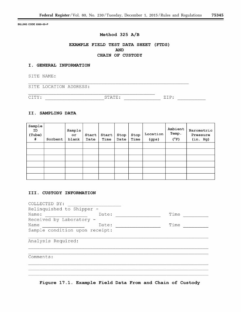
75345 Federal Register / Vol. 80, No. 230 / Tuesday, December 1, 2015 / Rules and Regulations
BILLING CODE 6560–50–P
VerDate Sep<11>2014 23:11 Nov 30, 2015 Jkt 238001 PO 00000 Frm 00169 Fmt 4701 Sfmt 4725 E:\FR\FM\01DER2.SGM 01DER2 ER
01D
E15
.041
</G
PH
>
tkel
ley
on D
SK
3SP
TV
N1P
RO
D w
ith R
ULE
S2
Method 325 A/B
EXAMPLE FIELD TEST DATA SHEET (FTDS) AND
CHAIN OF CUSTODY
I. GENERAL INFORMATION
SITE NAME:
SITE LOCATION ADDRESS:
CITY: STATE: ZIP:
II. SAMPLING DATA
Sample Ambient ID Sample Barometric
(Tube) or Start Start Stop Stop Location Temp. Pressure # Sorbent blank Date Time Date Time (gps) (oF) (in. Hg)
III. CUSTODY INFORMATION
COLLECTED BY: Relinquished to Shipper -Name: Date: Time Received by Laboratory -Name Date: Time Sample condition upon receipt:
Analysis Required:
Comments:
Figure 17.1. Example Field Data From and Chain of Custody
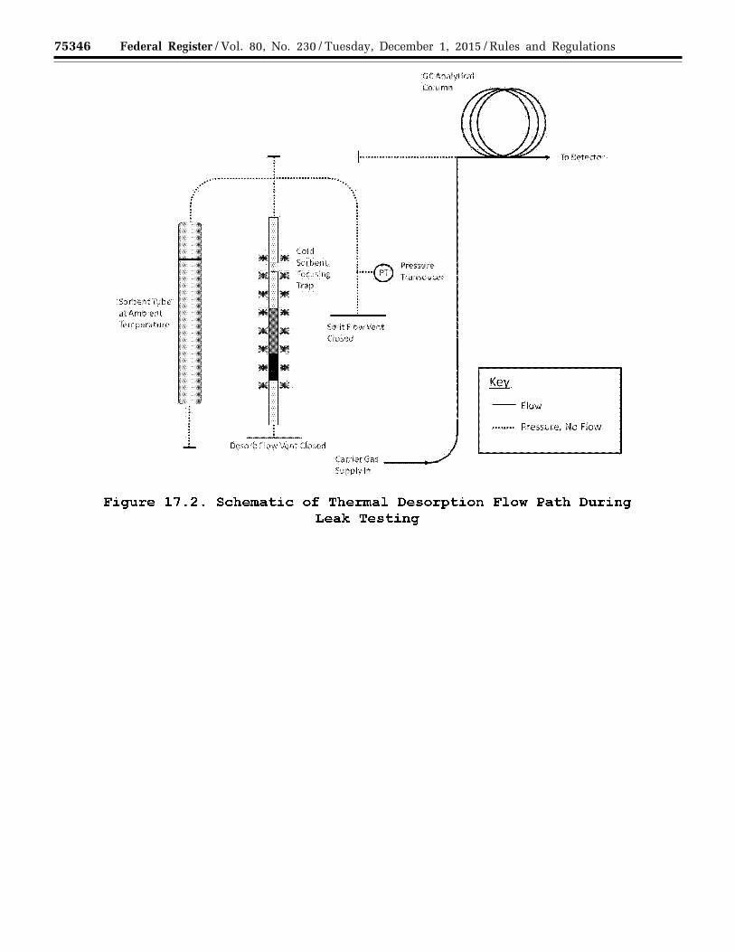
75346 Federal Register / Vol. 80, No. 230 / Tuesday, December 1, 2015 / Rules and Regulations
VerDate Sep<11>2014 23:11 Nov 30, 2015 Jkt 238001 PO 00000 Frm 00170 Fmt 4701 Sfmt 4725 E:\FR\FM\01DER2.SGM 01DER2 ER
01D
E15
.042
</G
PH
>
tkel
ley
on D
SK
3SP
TV
N1P
RO
D w
ith R
ULE
S2
SOrbentTube at Ambient Temperature
T l···························r·················~······ ••• \ I ' l : : : : . :
Cold M 1M Sorbeot
JiiC * Focusing Trap • • ••
:
I I·····® I
• * Split Flow Vent Closed
• • • • *
Desorb Flow Vent Closed
GCAoalytical Column
Pressure Transducer
CarrierGas ---...-Supplyln
To Detector
--Flow
•··••··· Pressure, No Flow
Figure 17.2. Schematic of Ther.mal Desorption Flow Path During Leak Testing
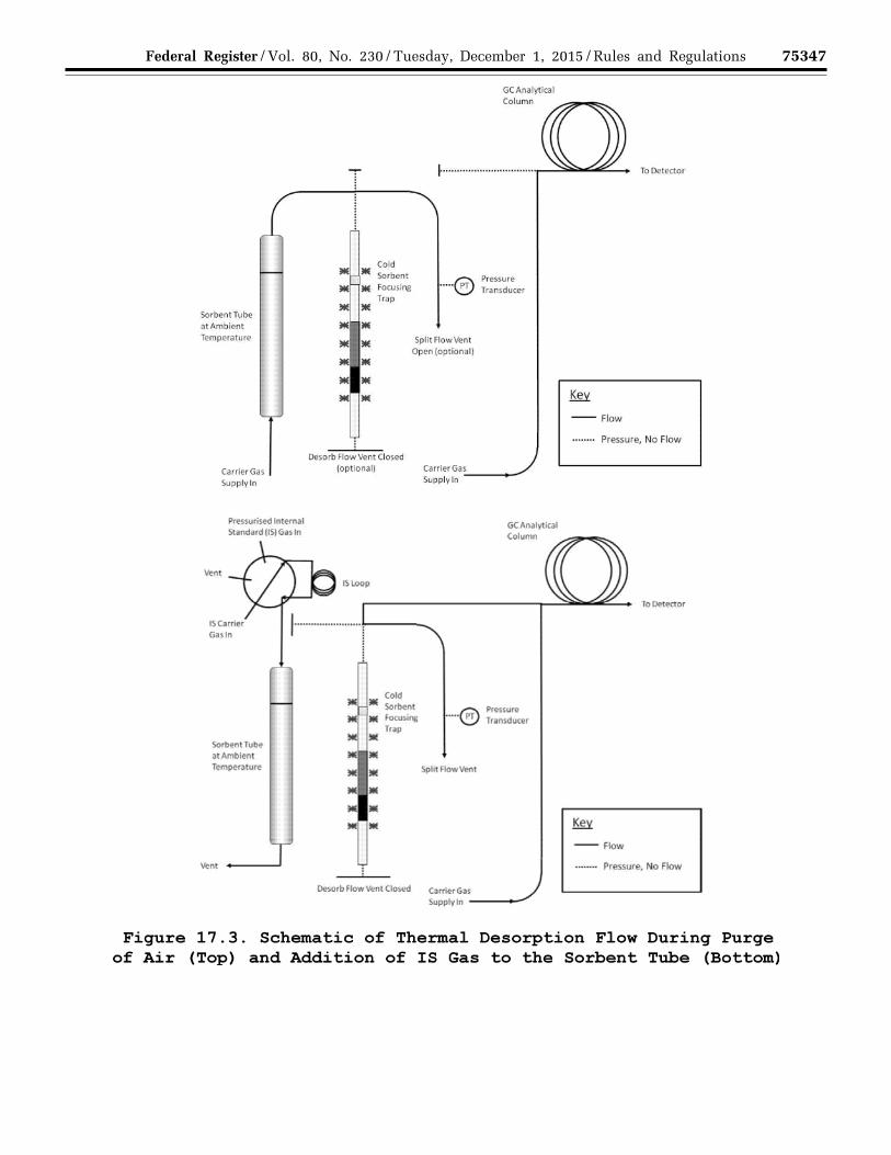
75347 Federal Register / Vol. 80, No. 230 / Tuesday, December 1, 2015 / Rules and Regulations
VerDate Sep<11>2014 23:11 Nov 30, 2015 Jkt 238001 PO 00000 Frm 00171 Fmt 4701 Sfmt 4725 E:\FR\FM\01DER2.SGM 01DER2 ER
01D
E15
.043
</G
PH
>
tkel
ley
on D
SK
3SP
TV
N1P
RO
D w
ith R
ULE
S2
SorbentTube at Ambient Temperature
Carrier Gas Supply In
Pressurised Internal Standard (IS) Gas In
SorbentTube at Ambient Temperature
liiE liiE
••
Cold Sorbent Focusing Trap
Desorb Flow Vent Closed
·····®
Split Flow Vent Open (optional)
GC Analytical Column
Pressure Transducer
(optional) CarrierGas;._ ___ ,
Supply In
Cold * Sorbent Ill( Focu~il'lll ·····@ *Trap
Ill • Split Flow Vent
• • •
GCAnalvtlcal Column
Pressure Tran•duCIIr
lQOetectcir
--Flow
•••••••• Pressure, No Flow
To Detector
--Flow
Vent •••••••• Pressure, No Flow
Desorb flow Vent Closlild Clrriet Gas
Sopplyln ----'
Figure 17.3. Schematic of Thermal Desorption Flow During Purge of Air (Top) and Addition of IS Gas to the Sorbent Tube (Bottom)
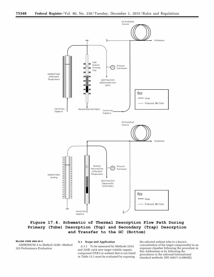
75348 Federal Register / Vol. 80, No. 230 / Tuesday, December 1, 2015 / Rules and Regulations
BILLING CODE 6560–50–C
ADDENDUM A to Method 325B—Method 325 Performance Evaluation
A.1 Scope and Application
A.1.1 To be measured by Methods 325A and 325B, each new target volatile organic compound (VOC) or sorbent that is not listed in Table 12.1 must be evaluated by exposing
the selected sorbent tube to a known concentration of the target compound(s) in an exposure chamber following the procedure in this Addendum or by following the procedures in the national/international standard methods: ISO 16017–2:2003(E),
VerDate Sep<11>2014 23:11 Nov 30, 2015 Jkt 238001 PO 00000 Frm 00172 Fmt 4701 Sfmt 4700 E:\FR\FM\01DER2.SGM 01DER2 ER
01D
E15
.044
</G
PH
>
tkel
ley
on D
SK
3SP
TV
N1P
RO
D w
ith R
ULE
S2
Sorbent TUbe at Elevated
Temperature
Carrier Gas Supply in
SorbentTube Coolin&
I
&Analytical Column
j I'::\ Pressure r···\!:!1 Transducer !
1 Split Row Vent
(Optional for Inlet Split)
Desorb Aow Vent Open Carder Gas. ___ _.
( ........................ .
i
Carrier Gas Supply in
Supply In
GCAnalytlcal Column
SQrbent I'::\ Pressure FocuslngTrap ••••v:.:.~ Transducer at Elevated
Temperature
Split Aow Vent (Optional for Outlet Split)
J !--··"
To l:letector
-Flow
•••···•· Pressure, No Flow
To l:letector
--Flow
•·•···•· Pressure, No Flow
Figure 17.4. Schematic of Ther.mal Desorption Flow Path During Primary (Tube) Desorption (Top) and Secondary (Trap) Desorption
and Transfer to the GC (Bottom)
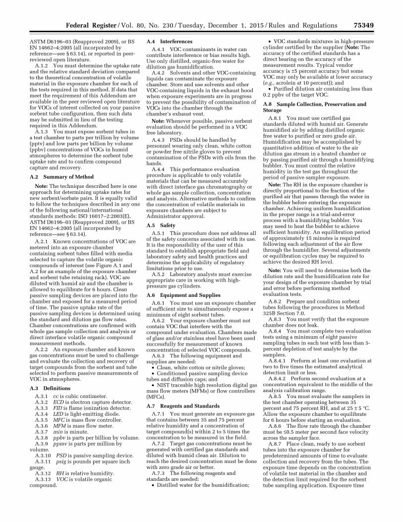
75349 Federal Register / Vol. 80, No. 230 / Tuesday, December 1, 2015 / Rules and Regulations
ASTM D6196–03 (Reapproved 2009), or BS EN 14662–4:2005 (all incorporated by reference—see § 63.14), or reported in peer- reviewed open literature.
A.1.2 You must determine the uptake rate and the relative standard deviation compared to the theoretical concentration of volatile material in the exposure chamber for each of the tests required in this method. If data that meet the requirement of this Addendum are available in the peer reviewed open literature for VOCs of interest collected on your passive sorbent tube configuration, then such data may be submitted in lieu of the testing required in this Addendum.
A.1.3 You must expose sorbent tubes in a test chamber to parts per trillion by volume (pptv) and low parts per billion by volume (ppbv) concentrations of VOCs in humid atmospheres to determine the sorbent tube uptake rate and to confirm compound capture and recovery.
A.2 Summary of Method
Note: The technique described here is one approach for determining uptake rates for new sorbent/sorbate pairs. It is equally valid to follow the techniques described in any one of the following national/international standards methods: ISO 16017–2:2003(E), ASTM D6196–03 (Reapproved 2009), or BS EN 14662–4:2005 (all incorporated by reference—see § 63.14).
A.2.1 Known concentrations of VOC are metered into an exposure chamber containing sorbent tubes filled with media selected to capture the volatile organic compounds of interest (see Figure A.1 and A.2 for an example of the exposure chamber and sorbent tube retaining rack). VOC are diluted with humid air and the chamber is allowed to equilibrate for 6 hours. Clean passive sampling devices are placed into the chamber and exposed for a measured period of time. The passive uptake rate of the passive sampling devices is determined using the standard and dilution gas flow rates. Chamber concentrations are confirmed with whole gas sample collection and analysis or direct interface volatile organic compound measurement methods.
A.2.2 An exposure chamber and known gas concentrations must be used to challenge and evaluate the collection and recovery of target compounds from the sorbent and tube selected to perform passive measurements of VOC in atmospheres.
A.3 Definitions
A.3.1 cc is cubic centimeter. A.3.2 ECD is electron capture detector. A.3.3 FID is flame ionization detector. A.3.4 LED is light-emitting diode. A.3.5 MFC is mass flow controller. A.3.6 MFM is mass flow meter. A.3.7 min is minute. A.3.8 ppbv is parts per billion by volume. A.3.9 ppmv is parts per million by
volume. A.3.10 PSD is passive sampling device. A.3.11 psig is pounds per square inch
gauge. A.3.12 RH is relative humidity. A.3.13 VOC is volatile organic
compound.
A.4 Interferences A.4.1 VOC contaminants in water can
contribute interference or bias results high. Use only distilled, organic-free water for dilution gas humidification.
A.4.2 Solvents and other VOC-containing liquids can contaminate the exposure chamber. Store and use solvents and other VOC-containing liquids in the exhaust hood when exposure experiments are in progress to prevent the possibility of contamination of VOCs into the chamber through the chamber’s exhaust vent.
Note: Whenever possible, passive sorbent evaluation should be performed in a VOC free laboratory.
A.4.3 PSDs should be handled by personnel wearing only clean, white cotton or powder free nitrile gloves to prevent contamination of the PSDs with oils from the hands.
A.4.4 This performance evaluation procedure is applicable to only volatile materials that can be measured accurately with direct interface gas chromatography or whole gas sample collection, concentration and analysis. Alternative methods to confirm the concentration of volatile materials in exposure chambers are subject to Administrator approval.
A.5 Safety A.5.1 This procedure does not address all
of the safety concerns associated with its use. It is the responsibility of the user of this standard to establish appropriate field and laboratory safety and health practices and determine the applicability of regulatory limitations prior to use.
A.5.2 Laboratory analysts must exercise appropriate care in working with high- pressure gas cylinders.
A.6 Equipment and Supplies A.6.1 You must use an exposure chamber
of sufficient size to simultaneously expose a minimum of eight sorbent tubes.
A.6.2 Your exposure chamber must not contain VOC that interfere with the compound under evaluation. Chambers made of glass and/or stainless steel have been used successfully for measurement of known concentration of selected VOC compounds.
A.6.3 The following equipment and supplies are needed:
• Clean, white cotton or nitrile gloves; • Conditioned passive sampling device
tubes and diffusion caps; and • NIST traceable high resolution digital gas
mass flow meters (MFMs) or flow controllers (MFCs).
A.7 Reagents and Standards A.7.1 You must generate an exposure gas
that contains between 35 and 75 percent relative humidity and a concentration of target compound(s) within 2 to 5 times the concentration to be measured in the field.
A.7.2 Target gas concentrations must be generated with certified gas standards and diluted with humid clean air. Dilution to reach the desired concentration must be done with zero grade air or better.
A.7.3 The following reagents and standards are needed:
• Distilled water for the humidification;
• VOC standards mixtures in high-pressure cylinder certified by the supplier (Note: The accuracy of the certified standards has a direct bearing on the accuracy of the measurement results. Typical vendor accuracy is ±5 percent accuracy but some VOC may only be available at lower accuracy (e.g., acrolein at 10 percent)); and
• Purified dilution air containing less than 0.2 ppbv of the target VOC.
A.8 Sample Collection, Preservation and Storage
A.8.1 You must use certified gas standards diluted with humid air. Generate humidified air by adding distilled organic free water to purified or zero grade air. Humidification may be accomplished by quantitative addition of water to the air dilution gas stream in a heated chamber or by passing purified air through a humidifying bubbler. You must control the relative humidity in the test gas throughout the period of passive sampler exposure.
Note: The RH in the exposure chamber is directly proportional to the fraction of the purified air that passes through the water in the bubbler before entering the exposure chamber. Achieving uniform humidification in the proper range is a trial-and-error process with a humidifying bubbler. You may need to heat the bubbler to achieve sufficient humidity. An equilibration period of approximately 15 minutes is required following each adjustment of the air flow through the humidifier. Several adjustments or equilibration cycles may be required to achieve the desired RH level.
Note: You will need to determine both the dilution rate and the humidification rate for your design of the exposure chamber by trial and error before performing method evaluation tests.
A.8.2 Prepare and condition sorbent tubes following the procedures in Method 325B Section 7.0.
A.8.3 You must verify that the exposure chamber does not leak.
A.8.4 You must complete two evaluation tests using a minimum of eight passive sampling tubes in each test with less than 5- percent depletion of test analyte by the samplers.
A.8.4.1 Perform at least one evaluation at two to five times the estimated analytical detection limit or less.
A.8.4.2 Perform second evaluation at a concentration equivalent to the middle of the analysis calibration range.
A.8.5 You must evaluate the samplers in the test chamber operating between 35 percent and 75 percent RH, and at 25 ± 5 °C. Allow the exposure chamber to equilibrate for 6 hours before starting an evaluation.
A.8.6 The flow rate through the chamber must be ≤0.5 meter per second face velocity across the sampler face.
A.8.7 Place clean, ready to use sorbent tubes into the exposure chamber for predetermined amounts of time to evaluate collection and recovery from the tubes. The exposure time depends on the concentration of volatile test material in the chamber and the detection limit required for the sorbent tube sampling application. Exposure time
VerDate Sep<11>2014 23:11 Nov 30, 2015 Jkt 238001 PO 00000 Frm 00173 Fmt 4701 Sfmt 4700 E:\FR\FM\01DER2.SGM 01DER2tkel
ley
on D
SK
3SP
TV
N1P
RO
D w
ith R
ULE
S2
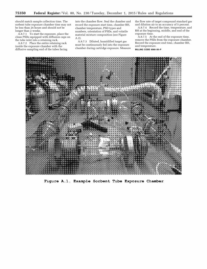
75350 Federal Register / Vol. 80, No. 230 / Tuesday, December 1, 2015 / Rules and Regulations
should match sample collection time. The sorbent tube exposure chamber time may not be less than 24 hours and should not be longer than 2 weeks.
A.8.7.1 To start the exposure, place the clean PSDs equipped with diffusion caps on the tube inlet into a retaining rack.
A.8.7.2 Place the entire retaining rack inside the exposure chamber with the diffusive sampling end of the tubes facing
into the chamber flow. Seal the chamber and record the exposure start time, chamber RH, chamber temperature, PSD types and numbers, orientation of PSDs, and volatile material mixture composition (see Figure A.2).
A.8.7.3 Diluted, humidified target gas must be continuously fed into the exposure chamber during cartridge exposure. Measure
the flow rate of target compound standard gas and dilution air to an accuracy of 5 percent.
A.8.7.4 Record the time, temperature, and RH at the beginning, middle, and end of the exposure time.
A.8.7.5 At the end of the exposure time, remove the PSDs from the exposure chamber. Record the exposure end time, chamber RH, and temperature. BILLING CODE 6560–50–P
VerDate Sep<11>2014 23:11 Nov 30, 2015 Jkt 238001 PO 00000 Frm 00174 Fmt 4701 Sfmt 4725 E:\FR\FM\01DER2.SGM 01DER2 ER
01D
E15
.045
</G
PH
>
tkel
ley
on D
SK
3SP
TV
N1P
RO
D w
ith R
ULE
S2
Figure A.l. Example Sorbent Tube Exposure Chamber
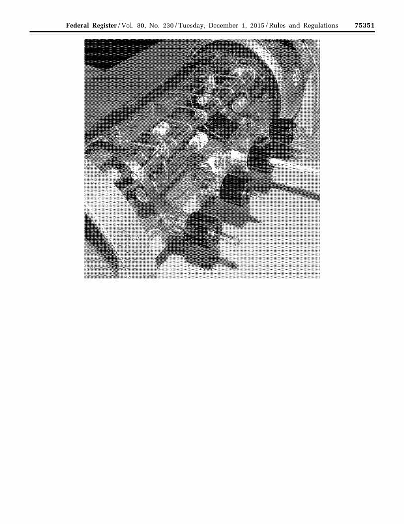
75351 Federal Register / Vol. 80, No. 230 / Tuesday, December 1, 2015 / Rules and Regulations
VerDate Sep<11>2014 23:11 Nov 30, 2015 Jkt 238001 PO 00000 Frm 00175 Fmt 4701 Sfmt 4725 E:\FR\FM\01DER2.SGM 01DER2 ER
01D
E15
.046
</G
PH
>
tkel
ley
on D
SK
3SP
TV
N1P
RO
D w
ith R
ULE
S2

75352 Federal Register / Vol. 80, No. 230 / Tuesday, December 1, 2015 / Rules and Regulations
BILLING CODE 6560–50–C
A.9 Quality Control
A.9.1 Monitor and record the exposure chamber temperature and RH during PSD exposures.
A.9.2 Measure the flow rates of standards and purified humified air immediately following PSD exposures.
A.10 Calibration and Standardization
A.10.1 Follow the procedures described in Method 325B Section 10.0 for calibration.
A.10.2 Verify chamber concentration by direct injection into a gas chromatograph calibrated for the target compound(s) or by collection of an integrated SUMMA canister followed by analysis using a preconcentration gas chromatographic method such as EPA Compendium Method TO–15, Determination of VOCs in Air Collected in Specially-Prepared Canisters and Analyzed By GC/MS.
A.10.2.1 To use direct injection gas chromatography to verify the exposure chamber concentration, follow the procedures in Method 18 of 40 CFR part 60,
Appendix A–6. The method ASTM D6420– 99 (Reapproved 2010) (incorporated by reference—see § 63.14) is an acceptable alternative to EPA Method 18 of 40 CFR part 60).
Note: Direct injection gas chromatography may not be sufficiently sensitive for all compounds. Therefore, the whole gas preconcentration sample and analysis method may be required to measure at low concentrations.
A.10.2.2 To verify exposure chamber concentrations using SUMMA canisters,
VerDate Sep<11>2014 23:11 Nov 30, 2015 Jkt 238001 PO 00000 Frm 00176 Fmt 4701 Sfmt 4700 E:\FR\FM\01DER2.SGM 01DER2 ER
01D
E15
.047
</G
PH
>
tkel
ley
on D
SK
3SP
TV
N1P
RO
D w
ith R
ULE
S2
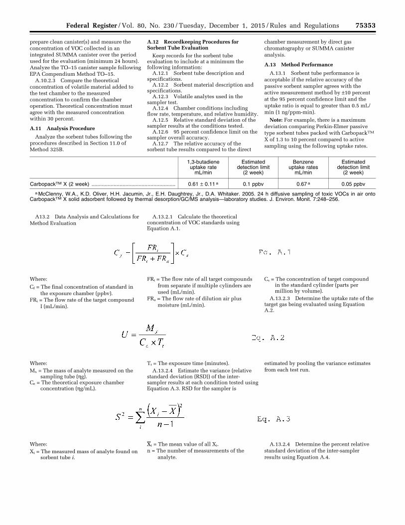
75353 Federal Register / Vol. 80, No. 230 / Tuesday, December 1, 2015 / Rules and Regulations
prepare clean canister(s) and measure the concentration of VOC collected in an integrated SUMMA canister over the period used for the evaluation (minimum 24 hours). Analyze the TO–15 canister sample following EPA Compendium Method TO–15.
A.10.2.3 Compare the theoretical concentration of volatile material added to the test chamber to the measured concentration to confirm the chamber operation. Theoretical concentration must agree with the measured concentration within 30 percent.
A.11 Analysis Procedure
Analyze the sorbent tubes following the procedures described in Section 11.0 of Method 325B.
A.12 Recordkeeping Procedures for Sorbent Tube Evaluation
Keep records for the sorbent tube evaluation to include at a minimum the following information:
A.12.1 Sorbent tube description and specifications.
A.12.2 Sorbent material description and specifications.
A.12.3 Volatile analytes used in the sampler test.
A.12.4 Chamber conditions including flow rate, temperature, and relative humidity.
A.12.5 Relative standard deviation of the sampler results at the conditions tested.
A.12.6 95 percent confidence limit on the sampler overall accuracy.
A.12.7 The relative accuracy of the sorbent tube results compared to the direct
chamber measurement by direct gas chromatography or SUMMA canister analysis.
A.13 Method Performance
A.13.1 Sorbent tube performance is acceptable if the relative accuracy of the passive sorbent sampler agrees with the active measurement method by ±10 percent at the 95 percent confidence limit and the uptake ratio is equal to greater than 0.5 mL/ min (1 ng/ppm-min).
Note: For example, there is a maximum deviation comparing Perkin-Elmer passive type sorbent tubes packed with CarbopackTM X of 1.3 to 10 percent compared to active sampling using the following uptake rates.
1,3-butadiene uptake rate
mL/min
Estimated detection limit
(2 week)
Benzene uptake rates
mL/min
Estimated detection limit
(2 week)
CarbopackTM X (2 week) ......................................................... 0.61 ± 0.11 a 0.1 ppbv 0.67 a 0.05 ppbv
a McClenny, W.A., K.D. Oliver, H.H. Jacumin, Jr., E.H. Daughtrey, Jr., D.A. Whitaker. 2005. 24 h diffusive sampling of toxic VOCs in air onto CarbopackTM X solid adsorbent followed by thermal desorption/GC/MS analysis—laboratory studies. J. Environ. Monit. 7:248–256.
A13.2 Data Analysis and Calculations for Method Evaluation
A.13.2.1 Calculate the theoretical concentration of VOC standards using Equation A.1.
Where:
Cf = The final concentration of standard in the exposure chamber (ppbv).
FRi = The flow rate of the target compound I (mL/min).
FRt = The flow rate of all target compounds from separate if multiple cylinders are used (mL/min).
FRa = The flow rate of dilution air plus moisture (mL/min).
Cs = The concentration of target compound in the standard cylinder (parts per million by volume).
A.13.2.3 Determine the uptake rate of the target gas being evaluated using Equation A.2.
Where: Mx = The mass of analyte measured on the
sampling tube (hg). Ce = The theoretical exposure chamber
concentration (hg/mL).
Tt = The exposure time (minutes). A.13.2.4 Estimate the variance (relative
standard deviation (RSD)) of the inter- sampler results at each condition tested using Equation A.3. RSD for the sampler is
estimated by pooling the variance estimates from each test run.
Where: Xi = The measured mass of analyte found on
sorbent tube i.
Xi = The mean value of all Xi. n = The number of measurements of the
analyte.
A.13.2.4 Determine the percent relative standard deviation of the inter-sampler results using Equation A.4.
VerDate Sep<11>2014 23:11 Nov 30, 2015 Jkt 238001 PO 00000 Frm 00177 Fmt 4701 Sfmt 4700 E:\FR\FM\01DER2.SGM 01DER2 ER
01D
E15
.048
</G
PH
>E
R01
DE
15.0
49<
/GP
H>
ER
01D
E15
.050
</G
PH
>
tkel
ley
on D
SK
3SP
TV
N1P
RO
D w
ith R
ULE
S2
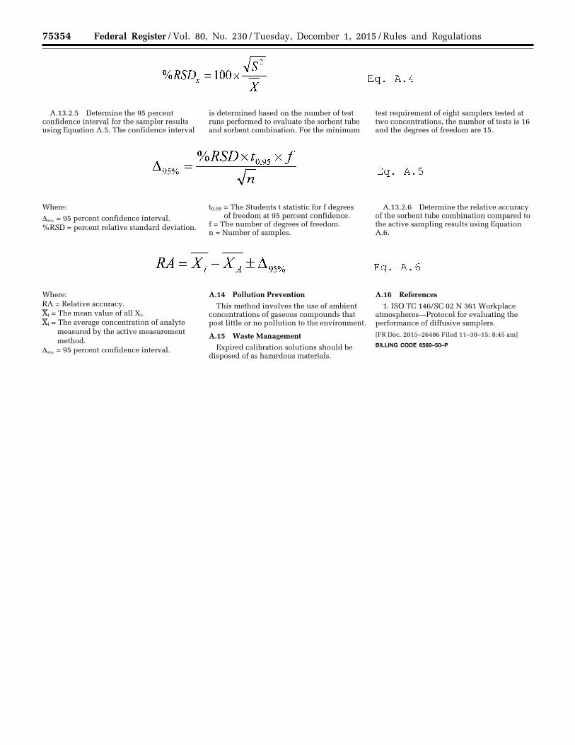
75354 Federal Register / Vol. 80, No. 230 / Tuesday, December 1, 2015 / Rules and Regulations
A.13.2.5 Determine the 95 percent confidence interval for the sampler results using Equation A.5. The confidence interval
is determined based on the number of test runs performed to evaluate the sorbent tube and sorbent combination. For the minimum
test requirement of eight samplers tested at two concentrations, the number of tests is 16 and the degrees of freedom are 15.
Where:
D95% = 95 percent confidence interval. %RSD = percent relative standard deviation.
t0.95 = The Students t statistic for f degrees of freedom at 95 percent confidence.
f = The number of degrees of freedom. n = Number of samples.
A.13.2.6 Determine the relative accuracy of the sorbent tube combination compared to the active sampling results using Equation A.6.
Where: RA = Relative accuracy. Xi = The mean value of all Xi. Xi = The average concentration of analyte
measured by the active measurement method.
D95% = 95 percent confidence interval.
A.14 Pollution Prevention
This method involves the use of ambient concentrations of gaseous compounds that post little or no pollution to the environment.
A.15 Waste Management
Expired calibration solutions should be disposed of as hazardous materials.
A.16 References
1. ISO TC 146/SC 02 N 361 Workplace atmospheres—Protocol for evaluating the performance of diffusive samplers.
[FR Doc. 2015–26486 Filed 11–30–15; 8:45 am]
BILLING CODE 6560–50–P
VerDate Sep<11>2014 23:11 Nov 30, 2015 Jkt 238001 PO 00000 Frm 00178 Fmt 4701 Sfmt 9990 E:\FR\FM\01DER2.SGM 01DER2 ER
01D
E15
.051
</G
PH
>E
R01
DE
15.0
52<
/GP
H>
ER
01D
E15
.053
</G
PH
>
tkel
ley
on D
SK
3SP
TV
N1P
RO
D w
ith R
ULE
S2