Embed Size (px)
Citation preview
This document transmits the Initial Issue of Service Bulletin TRENT1000-72-AK451
Bulletin Initial Issue
Remove Incorporate Reason for changePages 1 to 21 of theService Bulletin
Initial Issue
Page 1 and 2 ofAppendix 1
Initial Issue
Page 1 of Appendix 2 Initial Issue
Prin
ted
in G
reat
Brit
ain
Nov.14/19
TRENT 1000 SERIES PROPULSION SYSTEMS NON-MODIFICATION SERVICE BULLETIN
ALERT TRENT 1000 72 AK451Transmittal - Page 1 of 2
Date
ALERT
CHECK THAT ALL PREVIOUS TRANSMITTALS HAVE BEEN INCORPORATED If any have not been received please advise Customer Data Services, Rolls-Royce plc, Derby, England ©Rolls-Royce plc (date as above) Printed in Great Britain

LIST OF EFFECTIVE PAGES
The effective pages to this Service Bulletin are as follows:
Page Revision Number Revision Date
Bulletin1 Nov.14/192 Nov.14/193 Nov.14/194 Nov.14/195 Nov.14/196 Nov.14/197 Nov.14/198 Nov.14/199 Nov.14/1910 Nov.14/1911 Nov.14/1912 Nov.14/1913 Nov.14/1914 Nov.14/1915 Nov.14/1916 Nov.14/1917 Nov.14/1918 Nov.14/1919 Nov.14/1920 Nov.14/1921 Nov.14/19
Appendix 11 Nov.14/192 Nov.14/19
Appendix 21 Nov.14/19
Printed in Great B
ritain
TRENT 1000 72 AK451Transmittal - Page 2
1. Planning Information
A. Effectivity
(1) BOEING 787
TRENT 1000-AE3 Engines
TRENT 1000-CE3 Engines
TRENT 1000-D3 Engines
TRENT 1000-G3 Engines
TRENT 1000-H3 Engines
TRENT 1000-J3 Engines
TRENT 1000-K3 Engines
TRENT 1000-L3 Engines
TRENT 1000-M3 Engines
TRENT 1000-N3 Engines
TRENT 1000-P3 Engines
TRENT 1000-Q3 Engines
TRENT 1000-R3 Engines
(2) AIRBUS A330
TRENT 7000-72 Engines
TRENT 7000-72C Engines
B. Reason
(1) Problem
Cracking of the front air seal on IP Compressor (IPC) shaft assembly(72-32-31, 01-450, Part Number KH18436) has been identified during stripof a flight test vehicle. Subsequent inspections have identified twofurther examples of cracked front air seal on in-service engines. Thesecracks could propagate and have the potential to lead to in-flight events.
ENGINE - IP COMPRESSOR (IPC) SHAFT - BORESCOPE INSPECTION OF THE FRONT AIR SEAL -NON-MODIFICATION SERVICE BULLETIN - MOD.72-AK451
Prin
ted
in G
reat
Brit
ain
TRENT 1000 72 AK451Page 1 of 21
Nov.14/19Nov.14/19
TRENT 1000 SERIESSERVICE BULLETIN
(2) Safety Intent
The safety intent of this Non-Modification Service Bulletin (NMSB) is toidentify and remove cracked components from service which, if notaccomplished, could lead to high energy debris release and a potentiallyhazardous condition.
C. Description
This NMSB instructs the procedures for the initial inspection and repeats of anin-situ borescope inspection of the IP Compressor shaft assembly (72-32-31,01-450, Part Number KH18436) at a specific area between the fourth (rearmost)seal fin of the IP Compressor Shaft Assembly front air seal and the IPCompressor Stage 1 disc. This inspection procedure uses a standard 4mmborescope accessing the IP Compressor Stage 1 area through the Engine SectionStator (ESS) vanes. This inspection can be performed in shop and on-wing. Whereintervals allow, this inspection can be performed on-wing concurrently with:
BOEING 787 aircraft: AMM Task DMC-B787-A-R72-00-00-46A-280C-A, IPCompressor Stage 1 - Front Surface of the Blade Root Dovetail and RotorDisc Post (With a Borescope).
AIRBUS A330 aircraft: AMM TASK 72-00-00-00-290-848-A, Special DetailedInspection of the Intermediate Pressure Compressor Stage 1 - Front Surfaceof the Blade Root Dovetail and Rotor Disc Post (with a Borescope).
In both cases, access can alternatively be gained using the methoddescribed in the applicable AMM Task.
Accomplishment of this NMSB should be recorded in accordance with local NMSBtracking system procedures. A copy of the completed Appendix 1 or a similarform should be used to capture results along with photographic/video recording.
D. Compliance
This Non-Modification Service Bulletin is anticipated to be the subject of anEASA Airworthiness Directive.
Printed in Great B
ritain
TRENT 1000 72 AK451Page 2
Nov.14/19Nov.14/19
TRENT 1000 SERIESSERVICE BULLETIN
(1) IN-SHOP
ALERT
(a) Inspect the IP Compressor Shaft Assembly in accordance with Section3.A Accomplishment Instructions at engine shop visit, including thoseengines currently in-shop at time of issue of this NMSB.
NOTE: A shop visit is defined as the time from engine removal fromwing for the purpose of a visit to a Maintenance, Repair &Overhaul (MRO) facility until the time of dispatch of theengine(s) from the MRO facility to the operator. Any enginethat is in such condition at the date of issue of this NMSB isconsidered to be In-shop.
(b) A previous accomplishment of Service Bulletin 72-K452 or TechnicalVariance TV207889 may be considered as an acceptable means ofcompliance for the inspection set by Section 1.D.(1)(a).
(2) ON-WING
ALERT
(a) Inspect the IP Compressor Shaft Assembly in accordance with Section3.B Accomplishment Instructions as per the following schedule:
(i) Initial inspection to be completed before 500 cycles (IPCompressor Shaft Assembly cycles since new) or within 100cycles of issue date of this NMSB, whichever is later.
(ii) Repeat inspections to be completed at intervals not exceeding200 cycles.
(b) For IP Compressor Shaft Assemblies of greater than 700 cycles (IPCompressor Shaft Assembly cycles since new) at time of issue of thisNMSB, inspect the IP Compressor Shaft Assembly in accordance withSection 3.B Accomplishment Instructions as follows:
(i) Initial inspection to be completed within 50 cycles from issueof this NMSB.
(ii) Repeat inspection to be completed at intervals not exceeding200 cycles.
(c) For IP Compressor Shaft Assemblies of greater than 1000 cycles (IPCompressor Shaft Assembly cycles since new) at time of issue of thisNMSB, inspect the IP Compressor Shaft Assembly in accordance withSection 3.B Accomplishment Instructions as follows:
(i) Initial inspection to be completed within 25 cycles from issueof this NMSB or before 1st December 2019, whichever is sooner.
Prin
ted
in G
reat
Brit
ain
TRENT 1000 72 AK451Page 3
Nov.14/19Nov.14/19
TRENT 1000 SERIESSERVICE BULLETIN
(ii) Repeat inspection to be completed at intervals not exceeding200 cycles.
(d) A previous accomplishment of Service Bulletin 72-K452 or TechnicalVariance TV207889 In-shop or On-wing may be considered as anacceptable means of compliance for the initial inspection set byparagraphs (a)(i), (b)(i) or (c)(i) of Section 1.D.(2).
(e) Accomplishment of this NMSB In-shop (Section 1.D.(1)) may beconsidered as an acceptable means of compliance for the initial orrepeat inspection set by paragraphs (a)(i)/(ii), (b)(i)/(ii) or(c)(i)/(ii) of Section 1.D.(2).
NOTE: Accomplishment of this NMSB In-shop before 300 cycles (IPCompressor Shaft Assembly cycles since new) may be taken as anadditional one-time inspection. An additional initialinspection as per Section 1.D.(2).(a) is required to initiatethe repeat inspection regime.
E. Approval
The technical content of this Non-Modification Service Bulletin is approvedunder the authority of Design Organisation Approval EASA.21J.065 on Nov.14/19.
F. Manpower
(1) In-Shop
(a) Time to gain access
30 minutes (2 persons) - Estimated
(b) Time to inspect
45 minutes (2 persons) - Estimated
(c) Time to restore to serviceable condition
30 minutes (2 persons) - Estimated
(2) On-Wing
(a) Time to gain access
30 minutes (2 persons) - Estimated
(b) Time to inspect
45 minutes (2 persons) - Estimated
Printed in Great B
ritain
TRENT 1000 72 AK451Page 4
Nov.14/19Nov.14/19
TRENT 1000 SERIESSERVICE BULLETIN
(c) Time to restore to serviceable condition
30 minutes (2 persons) - Estimated
G. Material Price and Availability
Not applicable.
H. Tooling Price and Availability
(1) Flexible video-capable borescope, with a forward-view 0.157in (4 mm)diameter lens (STD-7028)
(2) Immobiliser - LP Compressor (HU44525-1/SPL-8907)
(3) Inlet Protective Mat (HU55142-1/SPL-9039)
(4) Engine Fan Cover (98K1010H005-000/SPL-8837)
(5) Engine Exhaust Cover (98K1010H006-000/SPL-8836)
(6) Rotor 1 Borescope Guide Tube (RRT108139/SPL-16443) or locally sourcedborescope guide tube - OPTIONAL
(7) OMat 150 (Acetone) or OMat 1/40 (Isopropyl Alcohol) - OPTIONAL
(8) OMat 582 (Ultrafine Scotch Brite) - OPTIONAL
(9) Delivery tube for OMat 150 (Acetone) or OMat 1/40 (Isopropyl Alcohol) -OPTIONAL
(10) Adhesive tape (OMat 283 or OMat 256) - OPTIONAL
I. References
(1) Aircraft Maintenance Manual (AMM):
(a) BOEING 787
(i) DMC-B787-A-R72-00-00-46A-280C-A, Intermediate PressureCompressor Stage 1 - Front Surface of the Blade Root Dovetailand Rotor Disc Post (with a Borescope) - Special DetailedInspection
(ii) DMC-B787-A-R72-00-00-01A-950A-A, Turn the Intermediate PressureSystem - Standard Practices
Prin
ted
in G
reat
Brit
ain
TRENT 1000 72 AK451Page 5
Nov.14/19Nov.14/19
TRENT 1000 SERIESSERVICE BULLETIN
(b) AIRBUS A330
(i) AMM TASK 72-00-00-00-290-848-A, Special Detailed Inspection ofthe Intermediate Pressure Compressor Stage 1 - Front Surface ofthe Blade Root Dovetail and Rotor Disc Post (with a Borescope)
(ii) AMM TASK 72-00-00-910-801-A, Turn the Intermediate PressureSystem - Standard Practices
(2) Rolls-Royce Non-Modification Service Bulletin:
(a) 72-K452
(i) ENGINE - IP COMPRESSOR (IPC) SHAFT BORESCOPE INSPECTION OF THEFRONT AIR SEAL - NON-MODIFICATION SERVICE BULLETIN
Printed in Great B
ritain
TRENT 1000 72 AK451Page 6
Nov.14/19Nov.14/19
TRENT 1000 SERIESSERVICE BULLETIN

2. Material Information
None
Prin
ted
in G
reat
Brit
ain
TRENT 1000 72 AK451Page 7
Nov.14/19Nov.14/19
TRENT 1000 SERIESSERVICE BULLETIN
3. Accomplishment Instructions
A. In-Shop
(1) Use the borescope equipment to do a visual inspection of the front airseal of the IP Compressor Shaft Assembly (72-32-31, 01-450).
(a) Assemble the applicable flexible video-capable borescope.
(b) If using a borescope guide tube:
(i) Carefully put the guide tube between the LP Compressor blades,through the ESS vanes and stop just before the cavity in frontof the IP Compressor Stage 1 blades. Refer to Fig.1.
It is recommended that access is gained at Top Dead Centre (TDC)to facilitate the borescope positioning into the engine.
The Variable Inlet Guide Vanes (VIGV) can prevent access from thefront of the engine. If the VIGV do prevent access, manuallyactuate the VIGV mechanism until a clear path to the IP CompressorStage 1 blades is seen from the front of the engine.
(ii) Attach the borescope guide tube to the engine with adhesivetape.
(iii) Carefully put the borescope through the borescope guide tube,until the borescope tip is into the cavity in front of the IPCompressor Stage 1 blades. Refer to Fig.1.
(c) If not using a borescope guide tube:
(i) Carefully put the borescope between the LP Compressor blades,through the ESS vanes and into the cavity in front of the IPCompressor Stage 1 blades. Refer to Fig.1.
It is recommended that access is gained at Top Dead Centre (TDC)to facilitate the borescope positioning into the engine.
The Variable Inlet Guide Vanes (VIGV) can prevent access from thefront of the engine. If the VIGV do prevent access, manuallyactuate the VIGV mechanism until a clear path to the IP CompressorStage 1 blades is seen from the front of the engine.
Printed in Great B
ritain
TRENT 1000 72 AK451Page 8
Nov.14/19Nov.14/19
TRENT 1000 SERIESSERVICE BULLETIN
(d) Slowly turn the IP system.
CAUTION: WHEN TURNING THE IP SYSTEM, ENSURE THAT THE ROTATION OFTHE BLADES IS AWAY FROM THE BORESCOPE TIP (FOR EXAMPLECOUNTER-CLOCKWISE, AFT LOOKING FORWARDS). IF THE SYSTEMIS TURNED TOWARDS THE BORESCOPE THEN THERE IS THEPOTENTIAL FOR TIP CRASH OR JAMMING OF THE IP SYSTEM.
CAUTION: MAKE SURE THAT THE BORESCOPE TIP IS NOT IN THE PATH OFTHE BLADES WHEN YOU TURN THE ENGINE. IF THE BORESCOPEAND THE BLADES TOUCH, DAMAGE TO THE BLADES OR BORESCOPECOULD OCCUR. THE GUIDE TUBE AND BORESCOPE SHOULD NOT BEINSERTED INTO THE ENGINE UNTIL THE ENGINE HAS COOLED TOWITHIN THE BORESCOPE MANUFACTURERS RECOMMENDATION.
(i) Use an applicable wrench to rotate the Hexagon drive on the IPTurning tool to slowly turn the IP system away from theborescope tip (for example counter-clockwise, aft lookingforwards).
(e) Perform a full 360 degree visual inspection of the surface between thefourth (rearmost) seal fin of the IP Compressor Shaft Assembly frontair seal (FIN 4 in Fig.2) and the IP Compressor Stage 1 disc (IPC1ROTOR in Fig.2). Refer to Fig.2 for the expected view through theborescope.
(i) Concentrate on looking for cracks which run at 90 degrees tothe seal fin (Forward to Aft of the engine). If doubt existsover the disposition of an observation, assume a crack ispresent.
NOTE: TO ACCOUNT FOR 360 DEGREES, EITHER USE THE IP COMPRESSORSTAGE 1 DISC DRAIN HOLES (QTY.2, LOCATED ADJACENT TO EACHOTHER) TO START AND FINISH THE INSPECTION, OR COUNT THEPASSAGE OF 35 IP COMPRESSOR STAGE 1 BLADE ROOTS.
(ii) To assist in sentencing crack like features in the inspectionarea it is permissible to clean the suspected area using theprocesses outlined in Appendix 2. Once cleaned the inspectioncan be repeated starting again from Step 3.A.(1).(b).
(f) Acceptance Standards
(i) If cracking is identified on the front air seal of the IPCompressor Shaft Assembly (72-32-31, 01-450):
(1) Make a photographic/video record of the finding.
Prin
ted
in G
reat
Brit
ain
TRENT 1000 72 AK451Page 9
Nov.14/19Nov.14/19
TRENT 1000 SERIESSERVICE BULLETIN
(2) REJECT the Engine (see NOTE below)
NOTE: To assist in sentencing crack-like features in theinspection area it is permissible to clean thesuspected area using the processes outlined inAppendix 2. Once cleaned the inspection can berepeated starting again from Step 3.A.(1).(b).
(ii) If no cracking is identified the Front Air seal of the IPCompressor Shaft Assembly (72-32-31, 01-450):
(1) ACCEPT the Engine
(g) After completion of the borescope inspection, carefully remove theborescope equipment and the Rotor 1 Borescope Guide Tube (if used).
(h) Record accomplishment of this Non-Modification Service Bulletin in themodule log card and the engine logbook against EIPC Ref 72-32-31,01-450.
(i) A copy of the completed Appendix 1 or a similar form should beused to capture results.
B. On-Wing
WARNING: YOU MUST BE CAREFUL WHEN YOU WORK ON THE ENGINE AFTER THE ENGINEIS SHUT DOWN. THE ENGINE CAN STAY HOT FOR ALMOST ONE HOUR. DONOT TOUCH HOT PARTS WITHOUT THE APPLICABLE GLOVES. HOT PARTS CANCAUSE INJURIES TO PERSONNEL.
CAUTION: IN ORDER TO REDUCE THE POTENTIAL FOR MULTIPLE ENGINE IN-FLIGHTSHUTDOWN, POWER LOSS, OR OTHER ANOMALY DUE TO MAINTENANCE ERROR,ROLLS-ROYCE RECOMMENDS THAT OPERATORS AVOID PERFORMINGMAINTENANCE ON MULTIPLE ENGINES INSTALLED ON THE SAME AIRCRAFTAT THE SAME TIME. IF IT IS NOT POSSIBLE TO AVOID MAINTENANCE ONMORE THAN ONE ENGINE AT THE SAME TIME, ROLLS-ROYCE RECOMMENDSTHAT ADDITIONAL CONTROLS ARE APPLIED IN ORDER TO ENSURE THATMAINTENANCE TASKS HAVE BEEN COMPLETED AS DEFINED. MAINTENANCEGUIDELINES SHOULD BE REVISED, WHERE POSSIBLE, TO PROMOTE THISRECOMMENDATION.
(1) Prepare the aircraft for maintenance:
(a) For BOEING 787 aircraft:
Prepare the engine for inspection in accordance withDMC-B787-A-R72-00-00-46A-280C-A, Intermediate Pressure CompressorStage 1 - Front Surface of the Blade Root Dovetail and Rotor Disc Post(with a Borescope) - Special Detailed Inspection.
Printed in Great B
ritain
TRENT 1000 72 AK451Page 10
Nov.14/19Nov.14/19
TRENT 1000 SERIESSERVICE BULLETIN
(b) For AIRBUS A330 aircraft:
Prepare the engine for inspection in accordance with AMM Task72-00-00-290-848-A, Special Detailed Inspection of the IntermediatePressure Compressor Stage 1 - Front Surface of the Blade Root Dovetailand Rotor Disc Post (with a Borescope), 3. Job Set-up.
(2) Procedure:
Use the borescope equipment to do a visual inspection of the front airseal of the IP Compressor Shaft Assembly (KH18436):
(a) Assemble the applicable flexible video-capable borescope.
(b) Carefully put the borescope into the engine to view the areaidentified in Fig.2.
For access through the engine inlet and LP Compressor fan blades,refer to Fig.1. It is recommended that access is gained at Top DeadCentre (TDC) to facilitate the borescope positioning into the engine.A Borescope Guide Tube may be used to facilitate the positioning ofthe borescope, refer to Section 3.A.(1)(b) for guidance on how toinstall the guide tube.
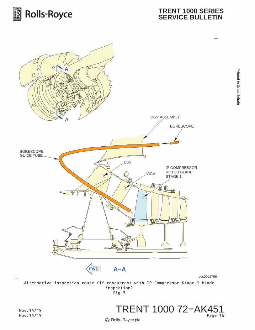
For access through the Outlet Guide Vanes (OGV) using a guide tube (ifperformed concurrently with IP Compressor Stage 1 blade inspections)refer to Fig.3 and applicable Aircraft Maintenance Manual inspectiontask.
(c) Slowly turn the IP system.
CAUTION: WHEN TURNING THE IP SYSTEM, ENSURE THAT THE ROTATION OFTHE BLADES IS AWAY FROM THE BORESCOPE TIP (I.E.COUNTER-CLOCKWISE, AFT LOOKING FORWARDS). IF THE SYSTEMIS TURNED TOWARDS THE BORESCOPE THEN THERE IS THEPOTENTIAL FOR TIP CRASH OR JAMMING OF THE IP SYSTEM.
CAUTION: MAKE SURE THAT THE BORESCOPE TIP IS NOT IN THE PATH OFTHE BLADES WHEN YOU TURN THE ENGINE. IF THE BORESCOPEAND THE BLADES TOUCH, DAMAGE TO THE BLADES OR BORESCOPECOULD OCCUR. THE GUIDE TUBE AND BORESCOPE SHOULD NOT BEINSERTED INTO THE ENGINE UNTIL THE ENGINE HAS COOLED TOWITHIN THE BORESCOPE MANUFACTURERS RECOMMENDATION.
(i) When required, turn the Intermediate Pressure system inaccordance with the applicable current maintenance procedures.
For BOEING 787 aircraft, Refer to DMC-B787-A-R72-00-00-01A-950A-A.
Prin
ted
in G
reat
Brit
ain
TRENT 1000 72 AK451Page 11
Nov.14/19Nov.14/19
TRENT 1000 SERIESSERVICE BULLETIN
For AIRBUS A330 aircraft, Refer to AMM TASK 72-00-00-910-801-A.
(d) Perform a full 360 degree visual inspection of the surface between thefourth (rearmost) seal fin of the IP Compressor Shaft Assembly frontair seal (FIN 4 in Fig.2) and the IP Compressor Stage 1 disc (IPC1ROTOR in Fig.2). Refer to Fig.2 for the expected view through theborescope.
(i) Concentrate on looking for cracks which run at 90 degrees tothe seal fin (Forward to Aft of the engine). If doubt existsover the disposition of an observation, assume a crack ispresent.
NOTE: TO ACCOUNT FOR 360 DEGREES, EITHER USE THE IP COMPRESSORSTAGE 1 DISC DRAIN HOLES (QTY.2, LOCATED ADJACENT TO EACHOTHER) TO START AND FINISH THE INSPECTION, OR COUNT THEPASSAGE OF 35 IP COMPRESSOR STAGE 1 BLADE ROOTS.
(ii) To assist in sentencing crack like features in the inspectionarea it is permissible to clean the suspected area using theprocesses outlined in Appendix 2. Once cleaned the inspectioncan be repeated starting again from Step 3.B.(2).(b).
(e) Acceptance Standards
(i) If cracking is identified on the front air seal of the IPCompressor Shaft Assembly (72-32-31, 01-450):
(1) Make a photographic/video record of the finding. Capture thisinformation in Appendix 1 (or similar).
(2) REJECT the Engine (see NOTE below)
NOTE: To assist in sentencing crack like features in theinspection area it is permissible to clean thesuspected area using the processes outlined inAppendix 2. Once cleaned the inspection can berepeated starting again from Step 3.B.(2).(b).
(ii) If no cracking is identified the Front Air seal of the IPCompressor Shaft Assembly (72-32-31, 01-450):
(1) ACCEPT the Engine.
(f) After completion of the borescope inspection, carefully remove theborescope equipment and the Rotor 1 Borescope Guide Tube (if used).
(g) Remove the IP Turning tool in accordance with applicable currentmaintenance procedures:
For BOEING 787 aircraft, refer to DMC-B787-A-R72-00-00-01A-950A-A
Printed in Great B
ritain
TRENT 1000 72 AK451Page 12
Nov.14/19Nov.14/19
TRENT 1000 SERIESSERVICE BULLETIN
For AIRBUS A330 aircraft, Refer to AMM TASK 72-00-00-910-801-A
(3) Close Up:
(a) For BOEING 787 aircraft:
Close up the engine in accordance withDMC-B787-A-R72-00-00-46A-280C-A, Intermediate Pressure CompressorStage 1 - Front Surface of the Blade Root Dovetail and Rotor Disc Post(with a Borescope) - Special Detailed Inspection, E. Put the AirplaneBack to its Usual Condition.
(b) For AIRBUS A330 aircraft:
Close up the engine in accordance with AMM Task 72-00-00-290-848-A,Special Detailed Inspection of the Intermediate Pressure CompressorStage 1 - Front Surface of the Blade Root Dovetail and Rotor Disc Post(with a Borescope), 5. Close-up.
(4) Record the accomplishment of this NMSB in accordance with local NMSBtracking system procedures.
(a) A copy of the completed Appendix 1 or a similar form should be used tocapture results.
Prin
ted
in G
reat
Brit
ain
TRENT 1000 72 AK451Page 13
Nov.14/19Nov.14/19
TRENT 1000 SERIESSERVICE BULLETIN
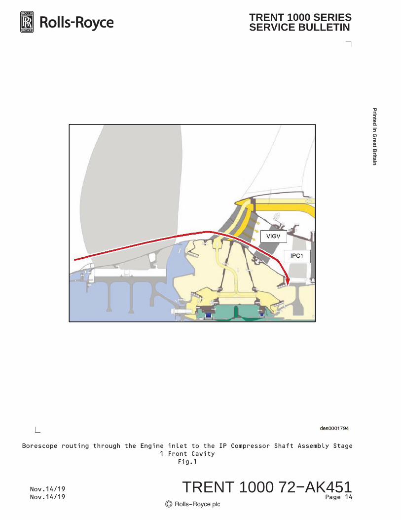
Borescope routing through the Engine inlet to the IP Compressor Shaft Assembly Stage1 Front Cavity
Fig.1
Printed in Great B
ritain
TRENT 1000 72 AK451Page 14
Nov.14/19Nov.14/19
TRENT 1000 SERIESSERVICE BULLETIN
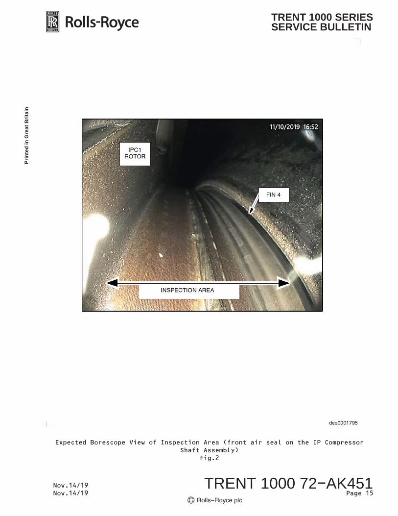
Expected Borescope View of Inspection Area (front air seal on the IP CompressorShaft Assembly)
Fig.2
Prin
ted
in G
reat
Brit
ain
TRENT 1000 72 AK451Page 15
Nov.14/19Nov.14/19
TRENT 1000 SERIESSERVICE BULLETIN
des0001796
BORESCOPE
OGV ASSEMBLY
GUIDE TUBE
A A
A
A
IP COMPRESSORROTOR BLADESTAGE 1
VIGV
ESS
BORESCOPE
Alternative inspection route (if concurrent with IP Compressor Stage 1 bladeinspection)
Fig.3
Printed in Great B
ritain
TRENT 1000 72 AK451Page 16
Nov.14/19Nov.14/19
TRENT 1000 SERIESSERVICE BULLETIN
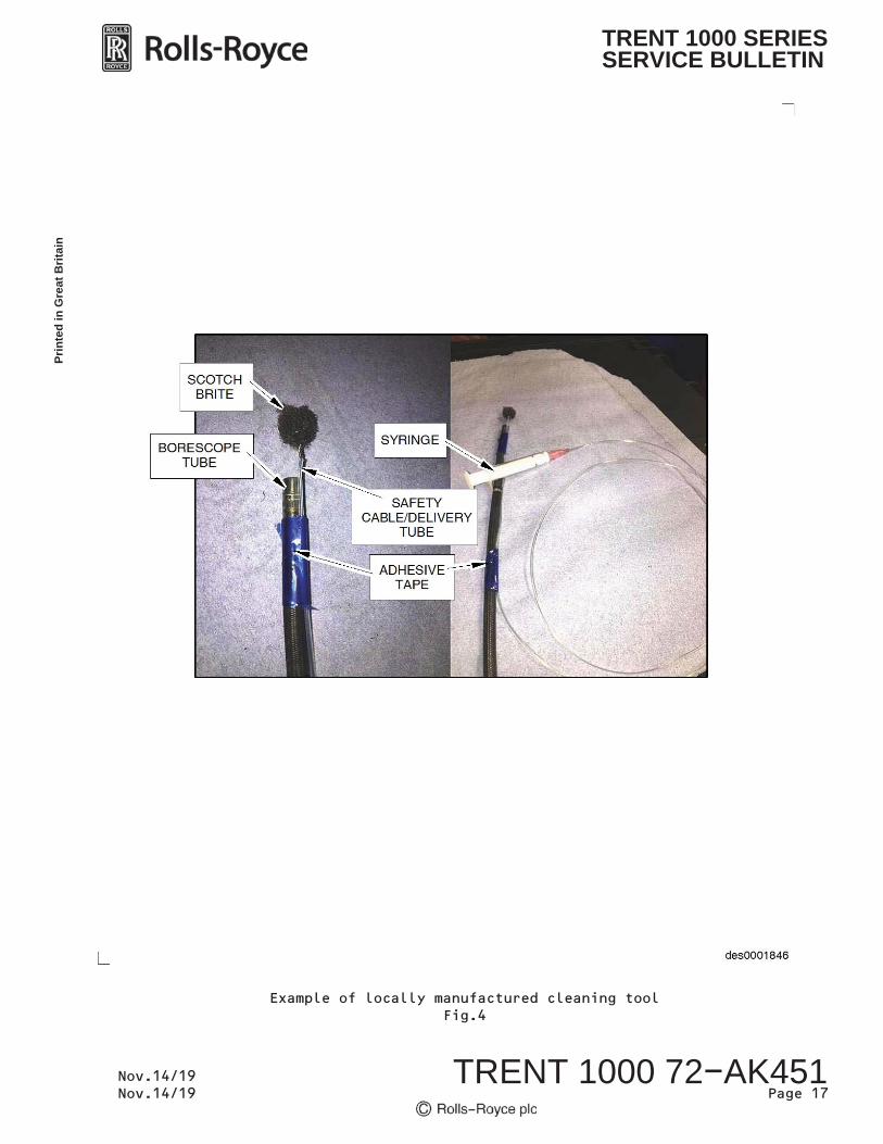
des0001846
SCOTCHBRITE
BORESCOPETUBE
SYRINGE
SAFETYCABLE/DELIVERY
TUBE
ADHESIVETAPE
Example of locally manufactured cleaning toolFig.4
Prin
ted
in G
reat
Brit
ain
TRENT 1000 72 AK451Page 17
Nov.14/19Nov.14/19
TRENT 1000 SERIESSERVICE BULLETIN

des0001847
SCOTCH BRITE
TAPE
2.5 mm diaPLASTIC TUBE
Example of locally manufactured cleaning tool.Fig.5
Printed in Great B
ritain
TRENT 1000 72 AK451Page 18
Nov.14/19Nov.14/19
TRENT 1000 SERIESSERVICE BULLETIN
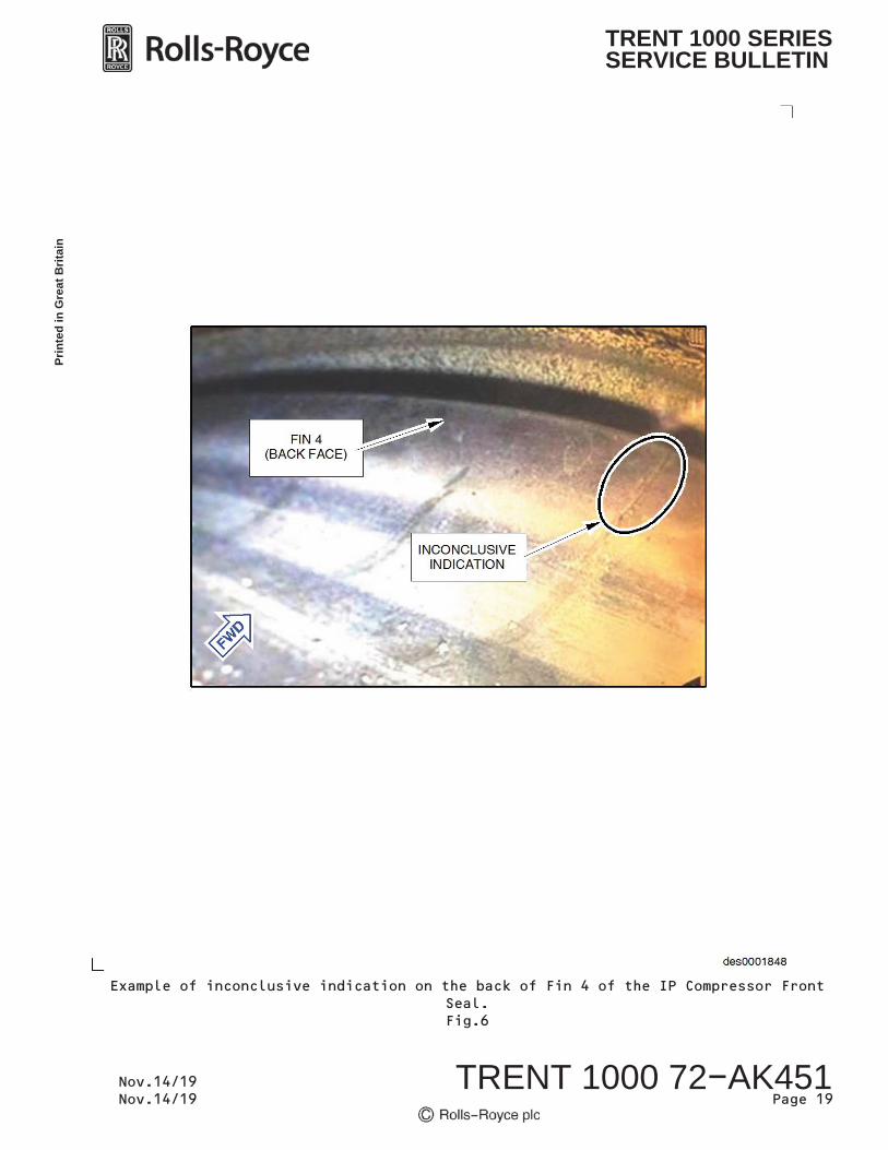
des0001848
INCONCLUSIVEINDICATION
FIN 4(BACK FACE)
Example of inconclusive indication on the back of Fin 4 of the IP Compressor FrontSeal.Fig.6
Prin
ted
in G
reat
Brit
ain
TRENT 1000 72 AK451Page 19
Nov.14/19Nov.14/19
TRENT 1000 SERIESSERVICE BULLETIN
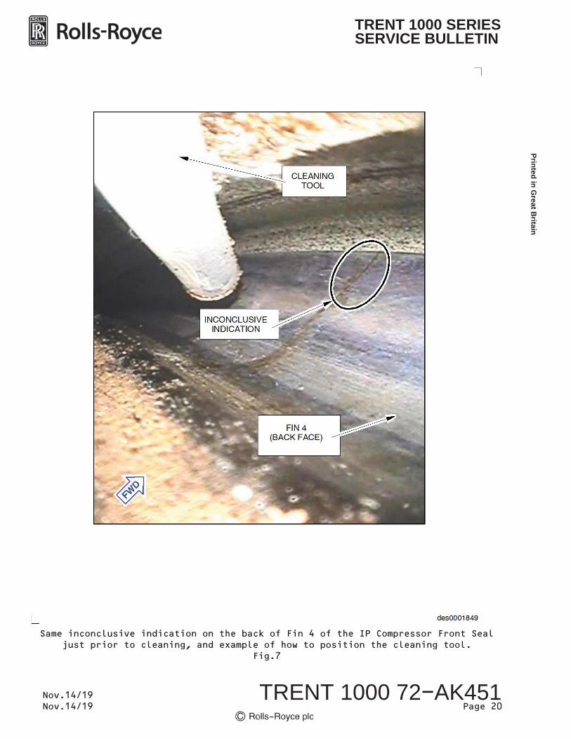
des0001849
CLEANINGTOOL
FIN 4(BACK FACE)
INCONCLUSIVEINDICATION
Same inconclusive indication on the back of Fin 4 of the IP Compressor Front Sealjust prior to cleaning, and example of how to position the cleaning tool.
Fig.7
Printed in Great B
ritain
TRENT 1000 72 AK451Page 20
Nov.14/19Nov.14/19
TRENT 1000 SERIESSERVICE BULLETIN
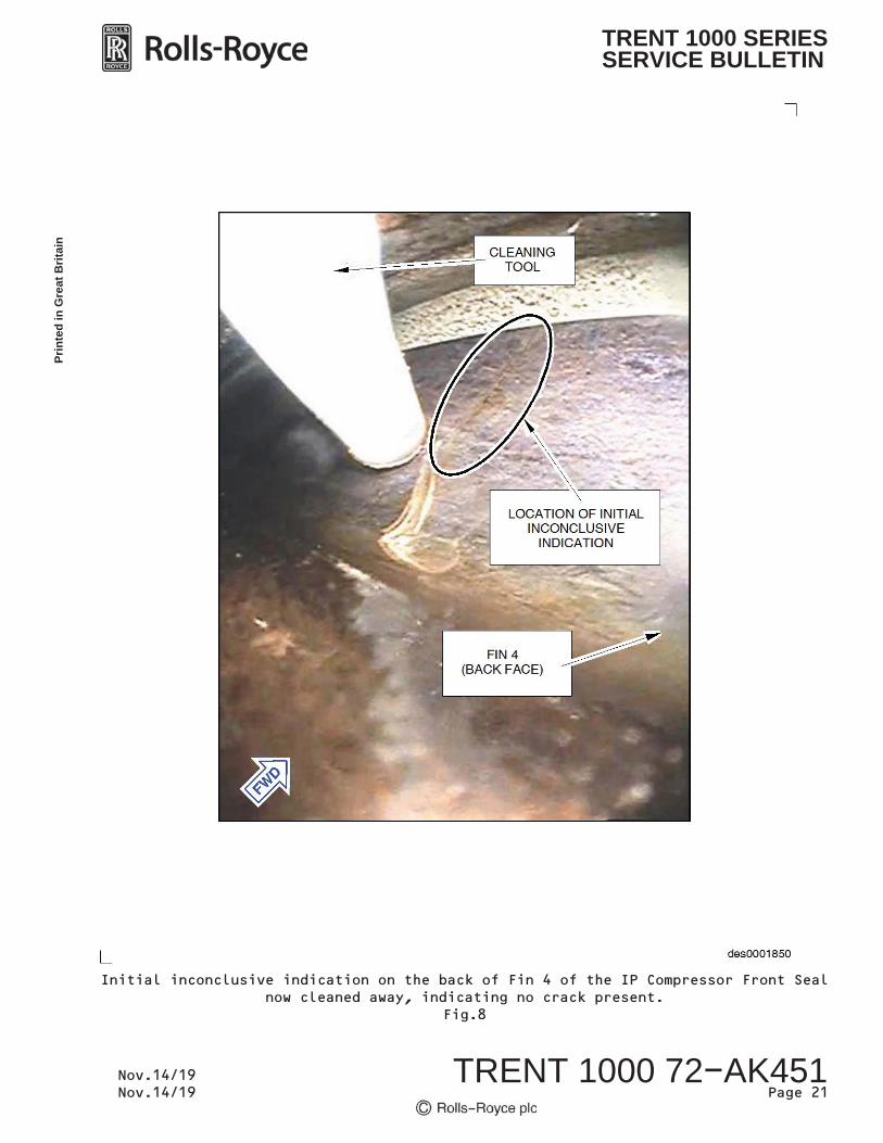
des0001850
FIN 4(BACK FACE)
CLEANINGTOOL
LOCATION OF INITIALINCONCLUSIVE
INDICATION
Initial inconclusive indication on the back of Fin 4 of the IP Compressor Front Sealnow cleaned away, indicating no crack present.
Fig.8
Prin
ted
in G
reat
Brit
ain
TRENT 1000 72 AK451Page 21
Nov.14/19Nov.14/19
TRENT 1000 SERIESSERVICE BULLETIN

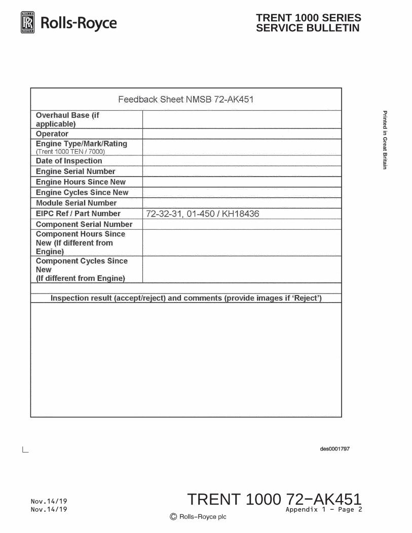
This form (or similar) to be completed for every engine/component inspected.
Results to be recorded within your local NMSB tracking system(s).
APPENDIX 1
Prin
ted
in G
reat
Brit
ain
TRENT 1000 72 AK451Appendix 1 - Page 1 of 2
Nov.14/19Nov.14/19
TRENT 1000 SERIESSERVICE BULLETIN
Printed in Great B
ritain
TRENT 1000 72 AK451Appendix 1 - Page 2
Nov.14/19Nov.14/19
TRENT 1000 SERIESSERVICE BULLETIN
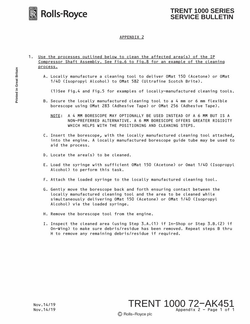
1. Use the processes outlined below to clean the affected area(s) of the IPCompressor Shaft Assembly. See Fig.6 to Fig.8 for an example of the cleaningprocess.
A. Locally manufacture a cleaning tool to deliver OMat 150 (Acetone) or OMat1/40 (Isopropyl Alcohol) to OMat 582 (Ultrafine Scotch Brite).
(1)See Fig.4 and Fig.5 for examples of locally-manufactured cleaning tools.
B. Secure the locally manufactured cleaning tool to a 4 mm or 6 mm flexibleborescope using OMat 283 (Adhesive Tape) or OMat 256 (Adhesive Tape).
NOTE: A 4 MM BORESCOPE MAY OPTIONALLY BE USED INSTEAD OF A 6 MM BUT IS ANON-PREFERRED ALTERNATIVE. A 6 MM BORESCOPE OFFERS GREATER RIGIDITYWHICH HELPS WITH THE POSITIONING AND CLEANING STEPS.
C. Insert the borescope, with the locally manufactured cleaning tool attached,into the engine. A locally manufactured borescope guide tube may be used toaid the process.
D. Locate the area(s) to be cleaned.
E. Load the syringe with sufficient OMat 150 (Acetone) or Omat 1/40 (IsopropylAlcohol) to perform this task.
F. Attach the loaded syringe to the locally manufactured cleaning tool.
G. Gently move the borescope back and forth ensuring contact between thelocally manufactured cleaning tool and the area to be cleaned whilesimultaneously delivering OMat 150 (Acetone) or OMat 1/40 (IsopropylAlcohol) via the loaded syringe.
H. Remove the borescope tool from the engine.
I. Inspect the cleaned area (using Step 3.A.(1) if In-Shop or Step 3.B.(2) ifOn-Wing) to make sure debris/residue has been removed. Repeat steps B thruH to remove any remaining debris/residue if required.
APPENDIX 2
Prin
ted
in G
reat
Brit
ain
TRENT 1000 72 AK451Appendix 2 - Page 1 of 1
Nov.14/19Nov.14/19
TRENT 1000 SERIESSERVICE BULLETIN