Embed Size (px)
Citation preview

Operations Manual
HKS700T
Operations Manual
Please read this manual before using. Engine S/N:
2010 August Ver.1.00 HKS CO.,LTD 7181 KITAYAMA FUJINOMIYA SHIZUOKA JAPAN 418-0192 TEL 0544-54-1781 FAX 0544-54-1410 [email protected] http://www.hks-power.co.jp/hks_aviation/
Operations Manual HKS 700T
1
CONTENTS 1 GENERAL
1.1 Log of revisions. 2 HKS700T ENGINE
2.1 Type designation. 2.2 Specifications: HKS-700T. 2.3 Views of the engine.
3 TECHNICAL DATA HKS-700T
3.1 Dimensions and weights. 3.2 Equipment. 3.3 Performance. 3.4 RPM limitations. 3.5 Fuel consumption. 3.6 Information about fuels and lubricants. 3.7 The cooling system. 3.8 Cylinder head temperatures. 3.9 Propeller reduction unit.
3.9.1 Propeller mass moment of inertia 3.10 Exhaust gas temperature 3.11 Manifold pressure 3.12 Service Ceiling 3.13 Permissible ambient temperature range 3.14 ECU workable ambient temperature range
4 PERFORMANCE CURVE 5 MANUAL OF INSTRUCTION HKS-700T
5.1 Before starting the engine. 5.2 Starting the engine. 5.3 Warm up and run up. 5.4 Take-off and climbing flight. 5.5 Engine shutdown. 5.6 Stopping the engine and restarting in flight.
Operations Manual HKS 700T
2
6 MAINTENANCE INSTRUCTIONS 6.1 Daily inspection. 6.2 Periodic checks.
6.2.1 First 25-hour-check, 50-hour-check 6.2.2 100-hour-check. 6.2.3 200-hour-check.
6.3 Preservation of the engine during storage 6.4 Winter operation.
6.4.1 Care of the electrical system. 7 MAINTENANCE
7.1 Changing oil. 7.2 Air intake filter. 7.3 Compression test. 7.4 Throttle adjustment.
7.4.1 Idle speed adjustment. 7.4.2 Throttle cable adjustment.
7.5 Spark plugs. 7.6 Exhaust system. 7.7 Bolts and nuts.
8 OVERHAULS
8.1 Thorough inspections (TBO). 8.2 Major repairs and major modifications.
9 TABLE FOR TORQUE VALUES 10 INSPECTION AND MAINTENANCE ITEMS

Operations Manual HKS 700T
3
Do not operate this engine over densely populated areas. Do not operate this engine over terrain where a safe, power off landing cannot be performed. The operating and maintenance instructions supplied with this engine must be followed at all times. Flying any aircraft involves the risk of injury or death, building and maintaining your own aircraft requires great personal responsibility.

Operations Manual HKS 700T
4
1. GENERAL 1.1. Log of revisions. Revision No. Date Pages affected Description Signature
Operations Manual HKS 700T
5
2. HKS700T ENGINE 2.1. Type designation. HKS-700T 1 2 3
1. Manufacturer: HKS. 2. Piston displacement in c.c. 3. Turbocharged
2.2. Description of the HKS-700T. Air-cooled, four-stroke. Cylinder arrangement: 2 cylinders, horizontally opposed. One central camshaft-pushrods-OHV, hydraulic lifters. Oil cooled cylinder head. Dual ECU Dual ignition. Electric starter. Alternator. Nickel ceramic composite coated cylinders. Dry sump forced lubrication. Turbocharger with intercooler.
Operations Manual HKS 700T
6
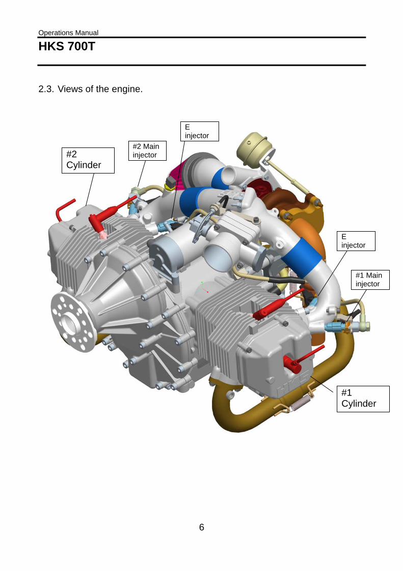
2.3. Views of the engine.
#1 Cylinder
#2 Cylinder
#1 Main injector
#2 Main injector
E injector
E injector
Operations Manual HKS 700T
7
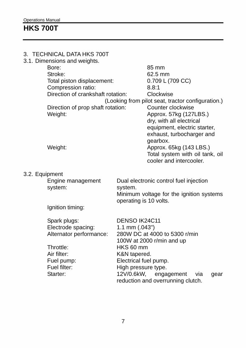
3. TECHNICAL DATA HKS 700T 3.1. Dimensions and weights.
Bore: 85 mm Stroke: 62.5 mm Total piston displacement: 0.709 L (709 CC) Compression ratio: 8.8:1 Direction of crankshaft rotation: Clockwise
(Looking from pilot seat, tractor configuration.)Direction of prop shaft rotation: Counter clockwise Weight: Approx. 57kg (127LBS.)
dry, with all electrical equipment, electric starter, exhaust, turbocharger and gearbox.
Weight: Approx. 65kg (143 LBS.) Total system with oil tank, oil cooler and intercooler.
3.2. Equipment
Engine management system:
Dual electronic control fuel injection system. Minimum voltage for the ignition systems operating is 10 volts.
Ignition timing:
Spark plugs: DENSO IK24C11 Electrode spacing: 1.1 mm (.043") Alternator performance: 280W DC at 4000 to 5300 r/min
100W at 2000 r/min and up Throttle: HKS 60 mm Air filter: K&N tapered. Fuel pump: Electrical fuel pump. Fuel filter: High pressure type. Starter: 12V/0.6kW, engagement via gear
reduction and overrunning clutch.

Operations Manual HKS 700T
8
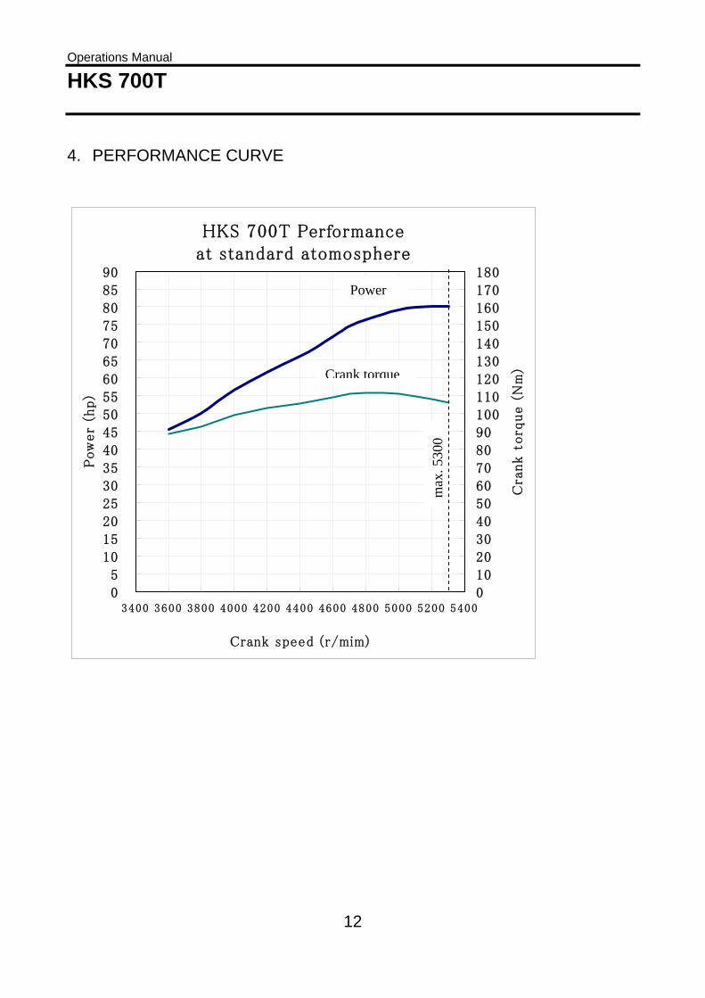
3.3. Performance Normal power
Take-off power (3 min.). Approx. 59.7kW (80HP) at 5300 r/min Max continuous power. Approx. 57.4kW (79HP) at 5000 r/min
CAUTION! Take-off power by wide open throttle must not be operated
continuously more than 3 minutes. Once it has been operated at wide open throttle continuously for more
than 3 minutes and the engine is damaged, the malfunction will be out of warranty.
The total time of wide open throttle operation must be within 5 minutes per hour.
3.4. RPM limitations
Max. permissible r/min 5300 r/min Max. continuous r/min 5000 r/min Idle r/min 1300 to 1600 r/min
3.5. Fuel consumption (With full throttle (loaded))
Consumption @ max. permissible r/min 35 L/H (9.2 GPH.) Consumption @ max. continuous r/min 28 L/H (7.4 GPH.)
Operations Manual HKS 700T
9
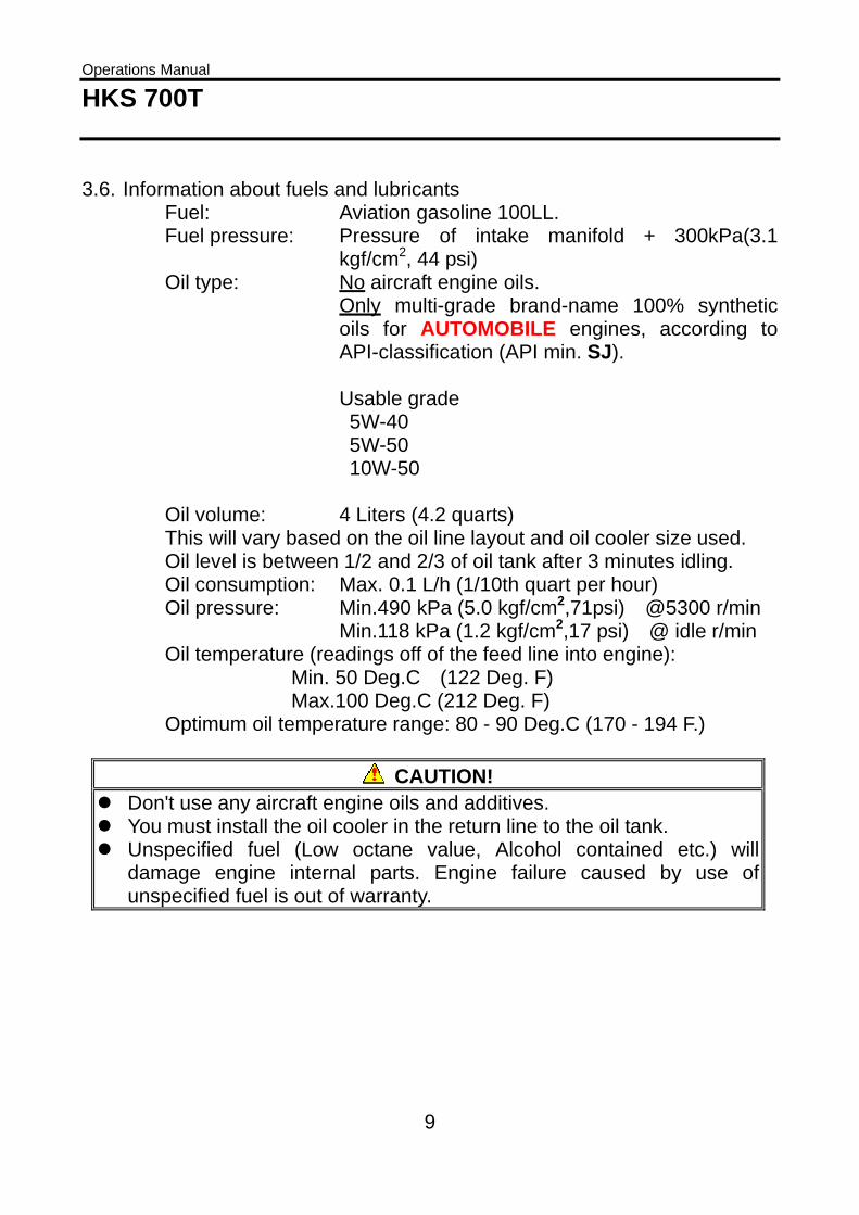
3.6. Information about fuels and lubricants Fuel: Aviation gasoline 100LL. Fuel pressure: Pressure of intake manifold + 300kPa(3.1
kgf/cm2, 44 psi) Oil type: No aircraft engine oils.
Only multi-grade brand-name 100% synthetic oils for AUTOMOBILE engines, according to API-classification (API min. SJ). Usable grade 5W-40 5W-50 10W-50
Oil volume: 4 Liters (4.2 quarts) This will vary based on the oil line layout and oil cooler size used. Oil level is between 1/2 and 2/3 of oil tank after 3 minutes idling. Oil consumption: Max. 0.1 L/h (1/10th quart per hour) Oil pressure: Min.490 kPa (5.0 kgf/cm2,71psi) @5300 r/min
Min.118 kPa (1.2 kgf/cm2,17 psi) @ idle r/min Oil temperature (readings off of the feed line into engine): Min. 50 Deg.C (122 Deg. F)
Max.100 Deg.C (212 Deg. F) Optimum oil temperature range: 80 - 90 Deg.C (170 - 194 F.)
CAUTION! Don't use any aircraft engine oils and additives.
You must install the oil cooler in the return line to the oil tank. Unspecified fuel (Low octane value, Alcohol contained etc.) will
damage engine internal parts. Engine failure caused by use of unspecified fuel is out of warranty.

Operations Manual HKS 700T
10
3.7. Cooling system Free air-cooling. For the engines with full-cowled engine installation, ducting is required to properly channel cooling air to the cylinders. 3.8. Cylinder head temperature Max. permissible cylinder head temperature (Measured on the hottest cylinder): 180 Deg. C (356 Deg. F) Optimum cylinder head temperature range: 140 - 170 Deg.C (284 - 338 F.) CAUTION! Use the HKS CHT probe. (Type K thermocouple)
Continuous operation at over CHT 180 Deg. C (356 Deg. F) will damage internal parts of engine. Engine failure caused by continuous operation at over CHT 180 Deg. C (356 Deg. F) is out of warranty.
3.9. Propeller drive-reduction gear Reduction ratio: crankshaft to prop shaft=2.61:1 Torsional shock absorption is based on progressive cushioning from an axial spring-loaded hub with dogs. 3.9.1. Propeller mass moment of inertia Max. permissible propeller mass moment of inertia 6000 kg cm^2 3.10. Exhaust gas temperature
Max. EGT [Deg. C] (Deg. F) : 780 (1436) at the original PT boss.
CAUTION! Continuous operation at over EGT 780 Deg. C (1436 Deg. F) will
damage internal parts of engine. Engine failure caused by continuous operation at over EGT 780 Deg. C (1436 Deg. F) is out of warranty.

Operations Manual HKS 700T
11
3.11. Manifold pressure Base boost pressure level Atmospheric pressure + 80kPa(0.816 kgf/cm2,11.6psi) Boost up function At CHT140 - 165 Deg.C (284 - 329 F.) Atmospheric pressure + 99kPa(1.01 kgf/cm2,14.3psi)
CAUTION! The pressure in intake manifold will be above mentioned pressure at
wide open throttle. When throttle opens less, the pressure will be also less.
3.12 Service Ceiling 5000m(16500feet) 3.13. Permissible ambient temperature range -20 Deg. C to 40 Deg. C. 3.14. ECU workable ambient temperature range ECU must be used at from -20 Deg. C to 75 Deg. C. Ensure that ECU is not submerged or no condensation.
Operations Manual HKS 700T
12
4. PERFORMANCE CURVE
HKS 700T Performanceat standard atomosphere
0
5
10
15
20
25
30
35
40
45
50
55
60
65
70
75
80
85
90
3400 3600 3800 4000 4200 4400 4600 4800 5000 5200 5400
Crank speed (r/mim)
Pow
er
(hp)
0
10
20
30
40
50
60
70
80
90
100
110
120
130
140
150
160
170
180
Cra
nk t
orq
ue (
Nm
)
Power
Crank torque
max
. 530
0
Operations Manual HKS 700T
13
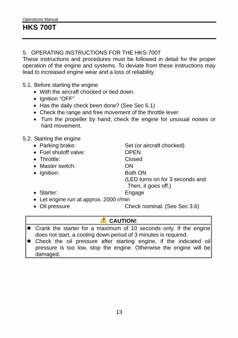
5. OPERATING INSTRUCTIONS FOR THE HKS-700T These instructions and procedures must be followed in detail for the proper operation of the engine and systems. To deviate from these instructions may lead to increased engine wear and a loss of reliability. 5.1. Before starting the engine
• With the aircraft chocked or tied down. • Ignition "OFF" • Has the daily check been done? (See Sec 6.1) • Check the range and free movement of the throttle lever. • Turn the propeller by hand; check the engine for unusual noises or
hard movement. 5.2. Starting the engine
• Parking brake: Set (or aircraft chocked) • Fuel shutoff valve: OPEN • Throttle: Closed • Master switch: ON • Ignition: Both ON
(LED turns on for 3 seconds and Then, it goes off.)
• Starter: Engage • Let engine run at approx. 2000 r/min • Oil pressure Check nominal. (See Sec 3.6)
CAUTION! Crank the starter for a maximum of 10 seconds only. If the engine
does not start, a cooling down period of 3 minutes is required. Check the oil pressure after starting engine, if the indicated oil
pressure is too low, stop the engine. Otherwise the engine will bedamaged.
Operations Manual HKS 700T
14
5.3. Warm up and run up • Let the engine run at 2000 r/min for 2 minutes. • Let the engine run at 2500-3000 r/min for about 5 minutes so that the
oil pressure will not exceed the 390kPa (57psi, 4bar) maximum during run up.
• Wait for the oil temperature to reach a minimum of 50 Deg. C (122 Deg.F) before taking off or running up to a high RPM.
• Perform a Mag check of the two ignition circuits at 3000 r/min. • Engine must not stop during Mag check.
5.4. Take-off and climb
• Advance the throttle smoothly and quickly to full throttle. • Perform the take-off and initial climb in this position, and then reduce
power slightly to the maximum continuous RPM, (See Sec. 3.3). CAUTION! Engine direction: within 20 degrees from vertical of gravitational force
direction. Observe RPM, oil temperature, cylinder head temperature, exhaust
gas temperature and oil pressure. The limits must not be exceeded. Ifthe temperatures are moving towards exceeding the describedlimitations, reduce engine power (if possible) and increase airspeed toimprove engine cooling.
5.5. Engine shutdown
• Let the engine cool sufficiently. Wait for the cylinder head temperature to reach less than 120Deg.C (248 Deg.F).
• Throttle: IDLE • Ignitions: OFF • Master switch: OFF
CAUTION! After taxiing with high power, let the engine cool sufficiently. Wait for the cylinder head temperature to reach less than 120Deg.C (248 Deg.F). Enough cooling down is required for full cowled aircraft to prevent heat problem.
Operations Manual HKS 700T
15
5.6. Engine shutdown and restarting in flight • Let the engine cool sufficiently. Wait for the cylinder head temperature
to reach less than 120Deg.C (248 Deg.F). • Throttle: IDLE • Ignitions: OFF
The in-flight re-start procedure is the same as on the ground.
Operations Manual HKS 700T
16
6. MAINTENANCE INSTRUCTIONS 6.1. Daily check
• Take off the engine cowling (if so equipped). • Check the engine for missing or loose parts as well as for any wear. • Check the condition of the ignition harness. • Check the actuating mechanisms for throttle, make certain that the
action of the throttle is smooth. • Check the oil level and fill if necessary. The oil level should be between
1/2 and 2/3rd of the oil tank dipstick or level gauge after 3 minutes idle running.
• Check the breather hoses of oil tank. The breather hoses must not choke.
• Check the oil and fuel system for any leakage. • Drain the sump(s) to remove water in the fuel tank. • Reattach the engine cowling if equipped. • With the ignition off, turn the propeller by hand and check the engine
for unusual noises or hard movement and proper compression. • Before flight engine test run.
Observe the starting behavior. Let the engine warm up, monitoring the temperatures and pressures. Do a run-up observing the throttle response (adequate RPM acceleration) and a full-power run-up. (Maximum RPM depends on the type of propeller and pitch used) DANGER! 1. Prior to turning the propeller by hand, confirm that. The ignition and master switches are: OFF
The aircraft is chocked or properly tied down. 2. Cockpit operations must be performed by a trained person.
Operations Manual HKS 700T
17
6.2. Periodic inspections After the first 25 hours of operation the inspections listed in 6.2.1 are to be performed. The next inspection is due to at 50 hours and thereafter every 50 hours. The 100-hour inspection mentioned under 6.2.2 is to be performed every 100 hours but at least annually. The 200-hour inspection mentioned under 6.2.3 is to be performed every 200 hours.
6.2.1. First 25-hour-inspection, 50-hour-inspection • Check condition of the throttle cable. • Engine mounts. Check for cracks, looseness of mounts, and
looseness of engine to mounts. • Check for looseness of bolts, nuts and pins. • Check for oil leaks from hoses, the oil tank and fittings. • Perform an oil change.(See Sec 7.1) • Check the magnet of oil drain screw for the metal contamination. • Change the oil filter. • Fuel lines-check the standoffs, safeties, leaks and wear. • Fuel filter-check, clean. • Check 4mm rubber hoses of fuel pressure regulator. • Check the ignition harness for damage and tight connections at spark
plug cap. • Air filter-check, clean. • Check rubber hoses of intercooler. • Check the general condition of the exhaust system; look for cracks,
particularly at the welds. • Check the attaching flanges at the exhaust ports on the cylinders for
exhaust leaks. • Check the ignition coils for wear and security of attachment. • Check for leaks at the oil pressure and temperature sensors. • Electrical wiring-check for wear, damage and security of attachment. • Check the resistance of the electrical equipment (See Sec 7.8). • Check the crankcase for leaks and cracks. • Clean engine if dirty or oily. • Run up the engine. (See Sec. 5.3) • Change fuses and rubber hoses every 3 years.

Operations Manual HKS 700T
18
6.2.2. 100-hour-inspection • Carry out the 50-hour-check. • Perform a compression check. (See Sec 7.3)
6.2.3. 200-hour-inspection
• Carry out the 100-hour inspection. • Check the spark plug caps. Change if necessary. • Change the spark plugs. • Change the fuel filter. • Change the air filter.

Operations Manual HKS 700T
19
6.3. Preservation of the engine for long term storage For long out of operation periods and at extreme climatic conditions, we recommend the following instructions to protect against corrosion. Extra protection against corrosion beyond these recommendations is not necessary.
1. Warm up the engine, stop the engine, and empty the motor oil. 2. Fill up with new oil. 3. Close all openings, the exhaust tubes, the breather tube and air filters.
Protect them against dirt and moisture. 4. Coat all the steel engine parts with engine oil.
Bringing the engine back to operation
1. Remove all the plugs and fasteners. CAUTION! For longer storage periods, the preservation procedures must beperformed at least annually.
6.4. Winter operation 6.4.1. Care of the electrical system Generally in the beginning of the winter an engine inspection shall be performed. • Check all the connections of the ignition system and clean if necessary. • Check the battery voltage. • The battery poles and terminal connectors should be cleaned.
In countries with extremely low temperatures it is recommended to protect the ECU and battery against freezing by keeping it in a warm location for storage between flights. (See Sec 3.6) ECU must be stored at from -30 Deg. C to 85 Deg. C. Ensure that there is no condensation. ECU Workable ambient temperature range : -20~+75℃
Storage temperature range : -30~+85℃
Ensure that there is no condensation.
Operations Manual HKS 700T
20
6.4.2. Fuel system icing (1) Icing due to water in the fuel Water in the fuel will accumulate at the lower parts of the fuel system and can lead to freezing of the fuel lines and filters. Remedies:
• Use a fuel/water separating funnel, if the fuel supply is suspect. • Drain the water in the fuel tank during the daily check. • Drain and inspect the fuel system during the 50-hour inspection. • Prevent fuel tank condensation, by keeping the fuel tank full when in
short term storage, drain the fuel tank when not in use for longer periods.
• Avoid temperature differences between aircraft and fuel.
CAUTION! Fuels containing alcohol always carry a small amount of water in solution.Temperature changes or an increase of alcohol content may cause wateror a mixture of alcohol and water to settle to the bottom of the fuel tankand could cause engine stoppage.
6.4.3. Induction system icing To prevent icing that blocks intake system, a shroud against icing should be equipped on the front side. 6.4.4. Venting system icing Attach I.D. 8mm venting tube to the 8mm nipple on the upper side of oil tank for atmospheric ventilation. To prevent icing around outlet of venting tube, length of venting tube should be shorter than 1000mm. To prevent fire of oil mist comes out of venting tube, outlet of venting tube should be at least 300mm far from exhaust system and should not face to the exhaust system.

Operations Manual HKS 700T
21
7. MAINTENANCE 7.1. Changing the engine oil
• Warm the engine up to normal operational temperatures. • Remove the oil drain screws from the engine and oil tank, drain oil, and
replace the oil filter. • Drain the oil from the oil cooler and oil lines. • Screw in the oil drain screws. Tighten according Chapter 9. • Fill with new oil in the oil tank (3L). • Run engine at idle for 3 minutes. • Recheck oil level of oil tank and fill if necessary, the oil level
should be between 1/2 and 2/3rd of the oil tank. CAUTION! (1) Use only multi-grade, brand name oils for automobile engines.
(Oil type See Sec. 3.6) (2) Don't use any aircraft engine oils and/or additives.
7.2. Air filter For operation in heavy dust conditions, clean the air filter at shorter intervals or replace. 7.3. Compression test Measure the engine compression using a compression gauge with a recording dial. The readings are taken with a fully open throttle at an engine oil temperature of between 86 Deg. F. (30 Deg. C) to 160 Deg. F. (70 Deg.C). If the readings are below 116 psi. (8 bar), A tear down to inspect the pistons, cylinders, valves and cylinder heads is required.
Operations Manual HKS 700T
22
7.3.1. Idle speed adjustment • For the first adjustment, turn back the stop screw so that the throttle
valves close completely. DANGER! The rotating propeller is extremely dangerous! Adjustments must be donewith the utmost caution from behind the engine. The aircraft must be tieddown or properly chocked. Do not perform this operation without a safetyobserver.
Operations Manual HKS 700T
23
7.4. Spark plugs • Unscrew the plugs only with a cold engine. • Brush clean with a plastic bristle brush. • Do not use a brass brush or a steel wire brush for cleaning. • After 200 hours, replacement of the spark plugs is required. • Spark plug to use: DENSO IK24C11 • Torque the spark plugs with a cold engine only. (See Chapter 9.)
The shade of the spark plugs can give you the following information: • Light brown to white:
Spark plugs and EFI system is correct. • Velvety black:
Electrode gap too wide or the mixture is too rich. Reduced air intake (air filter dirty) the proper exhaust gas temperature of engine is not reached
• Oily: The spark plug is not firing or worn cylinder and piston rings.
• Pearly or glazed: Wrong type of spark plug or the Spark plug not torqued properly, the mixture is a too lean or badly closing valve.
7.5. Exhaust system
• Visually check for any damage and or leaks. • Check attach-flanges at exhaust parts on cylinder. Tighten the nuts if
necessary. 7.6. Misc. bolts and nuts
• Check for tightness, re-torque if necessary (See chapter 9.)
Operations Manual HKS 700T
24
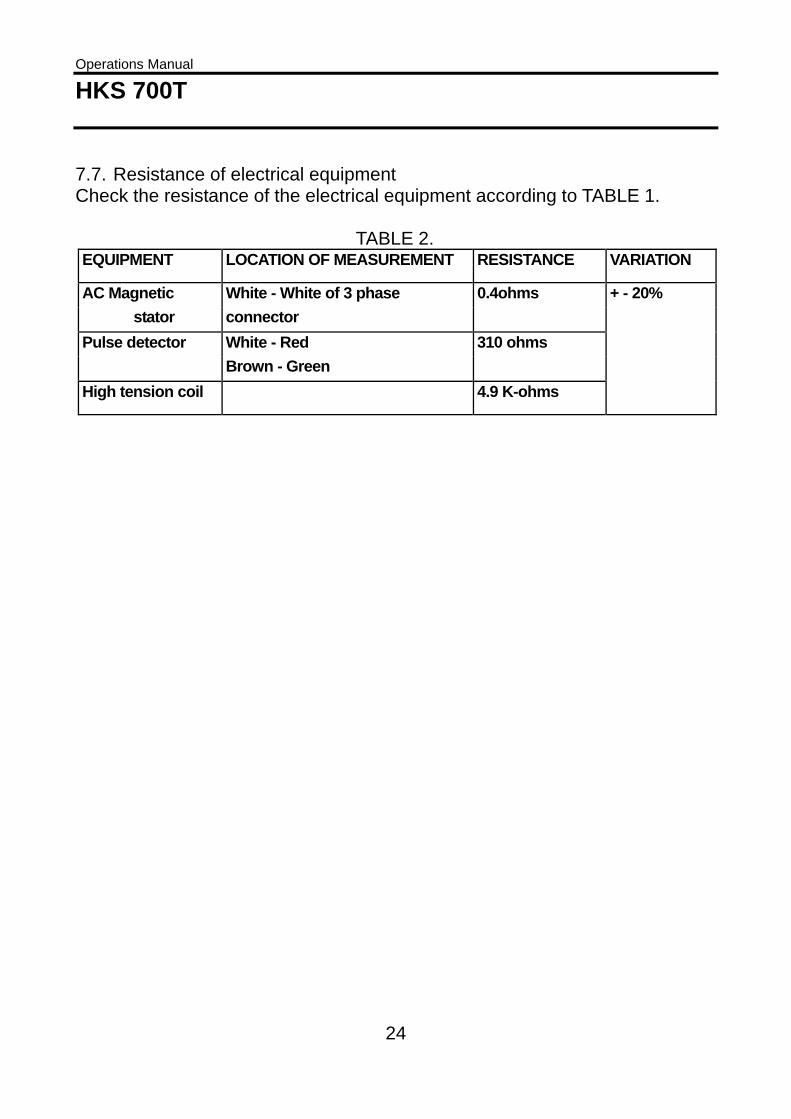
7.7. Resistance of electrical equipment Check the resistance of the electrical equipment according to TABLE 1. TABLE 2. EQUIPMENT LOCATION OF MEASUREMENT RESISTANCE VARIATION
AC Magnetic White - White of 3 phase 0.4ohms + - 20% stator connector Pulse detector White - Red 310 ohms Brown - Green High tension coil 4.9 K-ohms

Operations Manual HKS 700T
25
8. OVERHAULS 8.1. Major inspections at TBO is to be performed by the manufacturer or
approved service centers only. For this purpose the engine is to be sent with its logbook to the manufacturer or the nearest approved service center. The recommended time between overhaul (TBO) is at present 500 hours of operation and this overhaul must be performed within 8 years after shipping. An increase of TBO due to field experience will be published in the Service Bulletins of the manufacturer.
8.2. Major repairs and major modifications are also only to be performed
by the manufacturer or by approved service centers, which are authorized by the manufacturer. In case of prop strikes or sudden stoppage, the engine must be disassembled and the crankshaft must be checked for cracks. This is considered a major repair and must be performed by the manufacturer or an approved service center. If stoppage of the engine is concealed when ordering a repair or major overhaul, the responsibility for the damage and subsequent costs still exists for the owner concealing the damage.
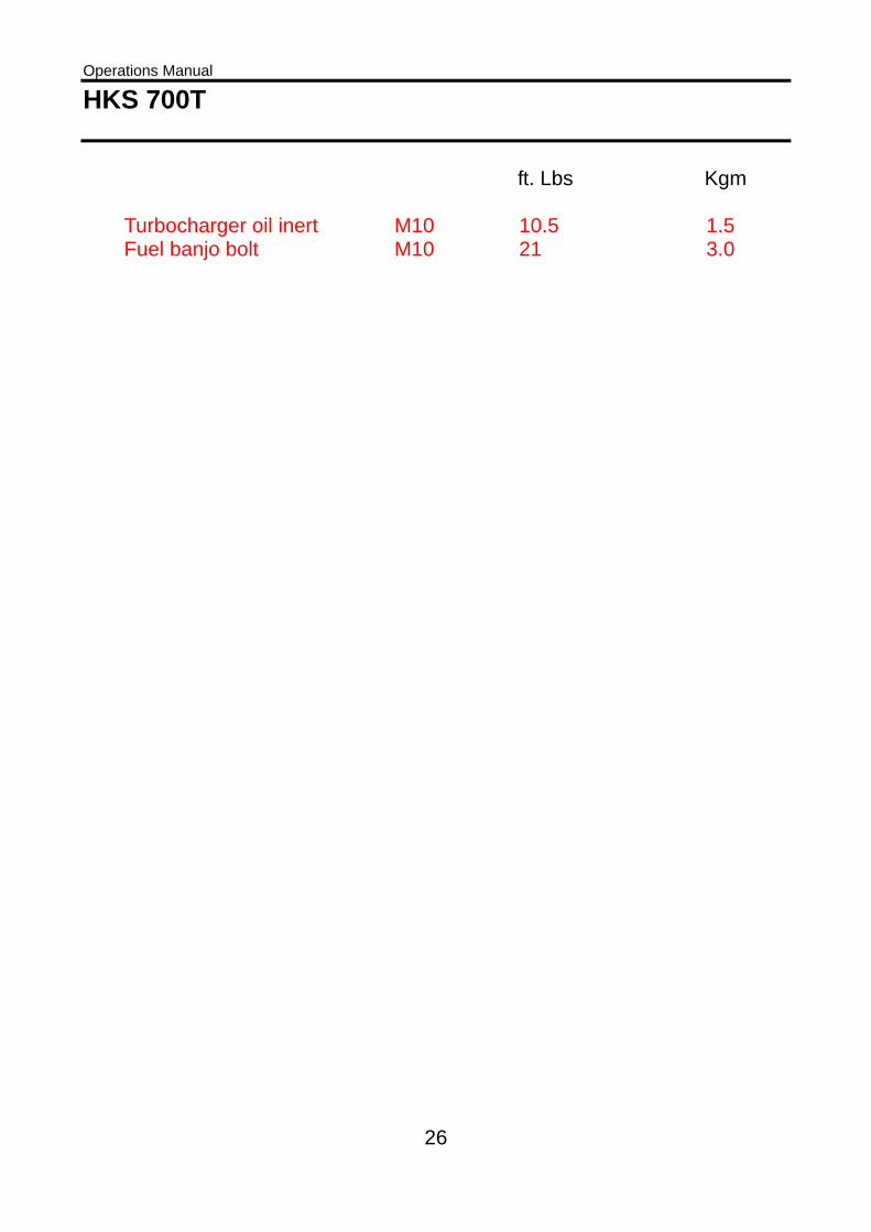
9. TABLE FOR TORQUE VALUES ft. Lbs Kgm
Spark plug M14 14.5 2 or 1/4 to 1/2 turn Oil drain screw M14 21 3 Rear cover screw M6 8.5 1.2 Oil pump screw M6 8.5 1.2 Crankcase screw M6 8.5 1.2
M8 17 2.4 M10 34.5 4.8
Front cover screw M6 8.5 1.2 Gear cover screw M6 8.5 1.2 Cylinder screw M6 7 1.0 Head screw M5 4 0.6 Head cover screw M5 4 0.6 Screw for starter M6 8.5 1.2 Intake manifold screw M8 17 2.4 Throttle M6 8.5 1.2 Turbocharger nut M8 17 2.4 Turbocharger bracket M8 21 3.0 Turbocharger oil return pipe M6 8.5 1.2
Operations Manual HKS 700T
26
ft. Lbs Kgm Turbocharger oil inert M10 10.5 1.5 Fuel banjo bolt M10 21 3.0

Operations Manual HKS 700T
27
10. INSPECTION AND MAINTENANCE ITEMS HKS-700T Inspection and maintenance program Inspection-maintenance item. Hourly inspection routine First Every Every Every 25hr. 50hr. 100hr. 200hr.1. Check condition of throttle cable. O O O O 2. Engine mounts-check for cracks, looseness of mounts,
and looseness of engine to mount. O O O O
3. Check for looseness of bolts, nuts and pins. O O O O 4. Check for oil leaks from hose, tank and fittings. O O O O 5. Exchange oil filter. O O O O 6. Perform oil change. O O O O 7. Check the magnet of oil drain screw for the metal
contamination. O O O O
8. Fuel lines-check for leaks, safeties and wear. O O O O 9. Fuel filter-check, clean or replace. O O O O 10. Check 4mm rubber hoses of fuel pressure regulator. O O O O 11. Check ignition harness for damage and tight
connections at spark plug cap. O O O O
12. Air filter-check, clean or replace. O O O O 13. Check rubber hoses of intercooler. O O O O 14. General condition of the exhaust system, Check
attaching flanges at exhaust port on cylinder forleakage.
O O O O
15. Check ignition coils for wear and security of attachment. O O O O 16. Check for leaks at oil pressure and temperature sensor. O O O O 17. Electrical wiring-check for damage, wear and security
of attachment. O O O O
18. Check resistance of electrical equipment. O O O O 19. Check crankcase for leaks and cracks. O O O O 20. Clean engine if dirty or oily. O O O O 21. Compression check (See operation manual). O O 22. Check spark plug caps. Change if necessary. O O 23. Change spark plugs. O 24. Change the fuel filter. O 25. Change the air filter. O 100-hr-inspections must be performed at least annually. The overhaul must be performedwithin 8 years after shipping or 500hours operation time.

Operations Manual HKS 700T
28
WARRANTEE CONDITIONS The HKS non-certified aircraft engines limited warrantees 1) Period HKS as manufacturer, warrants through their authorized HKS distributors from the date of sale to the first consumer, every HKS non-certified engines, sold as NEW and UNUSED, and delivered by an authorized HKS distributor for a period of the earliest of:
6 consecutive months for private use owners or 12 consecutive months from date of shipment of the HKS distributors or the first 100 operation hours
2) What an authorized HKS distributor will do The authorized HKS distributor will, at its option, repair and/or replace components defective in material and/or workman ship under normal use and service, with a genuine HKS component without charge for parts or labour, during said warrantee period. All parts replaced under warrantee become the property of HKS. 3) Condition to have warrantee work performed You must present to an authorized HKS service-center, the hard copy of the HKS warrantee registration card and/or proof of purchase delivered to the customer from the selling dealer at time of purchase. 4) Exclusion - are not warranted • Normal wear on all items. • Replacement parts and/or accessories that are not genuine HKS parts
and/or accessories. • Damage resulting from the installation of parts other than genuine HKS
parts. • Damage caused by failure to provide proper maintenance as detailed in
the OPERATIONS MANUAL. The labor, parts and lubricants costs of all maintenance services, including tune-ups and adjustments will be charged to the owner.
• Aircraft engines designed and/or used for racing or commercial purposes.
• All optional accessories installed on the aircraft engine (The normal warrantee policy for parts and accessories, if any, applies).
• Damage resulting from running the aircraft engine without propeller. • Damage resulting from modification to the aircraft engine not approved
in writing by HKS.
Operations Manual HKS 700T
29
• Damage caused by electrolysis. • Cold seizure and piston scuffing. • Use of a gear reduction not designed by HKS. • Use of propellers, which exceed the inertia and balance limits as
specified by HKS. • If engine instruments recommended by HKS have not been installed. • Losses incurred by the aircraft engine owner other than the parts and
labor, such as, but not limited to, mounting and dismounting of the engine from the aircraft, loss of use, transportation, towing, telephone calls, taxis, or any other incidental or consequential damage.
• Damage resulting from accident, fire or other casualty, misuse, abuse or neglect.
• Damage/rust/corrosion premature wear to the engine caused by water ingestion.
• Damage resulting from sand/stones infiltration. • Damage resulting from any foreign material ingestion. • Damage resulting from service by an unqualified mechanic.
5) Expressed or implied warrantees This warrantee gives you specific rights, and you may also have other legal rights, which may vary from state to state, or province to province. Where applicable this warrantee is expressly in lieu of all other expressed or implied warrantees of HKS, its distributors and the selling distributor, including any warrantee of merchantability or fitness for any particular purpose; otherwise the implied warrantee is limited to the duration of this warrantee. However, some states or provinces do not allow limitations on how long an implied warrantee lasts, so the above limitation may not apply. Neither the distributor, nor any other person has been authorized to make any affirmation, representation or warrantee other than those contained in this warrantee, and if made, such affirmation, representation or warrantee shall not be enforceable against HKS or any other person. HKS reserves the right to modify its warrantee policy at any time, being understood that such modification will not alter the warrantee conditions applicable to aircraft engines sold while the above warrantee is in effect.

Operations Manual HKS 700T
30
6) Consumer assistance procedure If a servicing problem or other difficulty occurs, please contact: -authorized HKS service-center or authorized HKS distributor. 7) Warrantee will only be valid if the end user completes this registration card as soon as the aircraft engine goes into service, and returns it to the national authorized HKS distributor of the area in which the aircraft engine is firstly operated. 8) This warrantee will be effective for all non-certified aircraft engines delivered by HKS as of September 1st, 1997. 9) WARNING! This is a non-certified aircraft engine, the possibility of engine failure exists at all times. Do not operate this engine over densely populated areas. Do not operate this engine over terrain where a safe, power off landing cannot be performed. The operating and maintenance instructions supplied with this engine must be followed at all times. Flying any aircraft involves the risk of injury or death, building and maintaining your own aircraft requires great personal responsibility. 10) All disputes, controversies or differences which may arise between the parties, shall be settled by arbitration in Japan in accordance with the Commercial Arbitration Rules of the Japan Commercial Arbitration Association.
Operations Manual HKS 700T
31
WARRANTEE CARD
WARRANTEE / OWNER'S REGISTRATION CARD
1. To be eligible for warrantee, this registration card must be returned completed and signed by the end user to the authorized HKS distribution partner of the area of the permanent residence of the end user and/or in which this non-certified aircraft engine is firstly operated, within 30 days as of date of purchase. 2. No other warrantees and/or guarantees than defined in the actual warrantee conditions are made. 3. All disputes, controversies or differences which may arise between the parties, shall be settled by arbitration in Japan in accordance with the Commercial Arbitration Rules of the Japan Commercial Arbitration Association. 4. Engine type: HKS700T Engine S/N.: Date of purchase: Buyer: Address: Telephone: Seller: I have read and understood the operations manual in its entirely. Date: Signature:

Mag check
3sec Warm up 5sec 3sec 5sec 3sec 2-4sec 3secat2000-3000rpm
MAIN SW ONIG SW 1 ON off ONLED 1 Light on off Slow blink Fast blink Light on Light on off Slow blink Light on
IG SW 2 ON off ON off ONLED 2 Light on off off Light on off Slow blink Fast blink Light on Light on
Condition Wiring check If LEDs turn off,wiring is OK.
Checking of IGcoil1. CheckingMain Injectors ofboth cylinders byECU1.
Checking of EInjector of bothcylinders byECU1.
Checkingdiagnosisfunction ofECU1
Checking of IGcoil2. CheckingMain Injectors ofboth cylinders byECU2.
Checking of EInjector of bothcylinders byECU2.
Checkingdiagnosisfunction of ECU2
Reset Normal condition
IG coil 1 ON off ON
IG coil 2 ON off ON
Mein Injector ON off ON off ON
E Injector off ON off ON off
BCV Light on Light on
Procedure of Mag check Close Throttle, turn on all of MainSW, IGSW1, IGSW2. Make sure that all LEDs are ON.
After 3 seconds, Warning LED1, 2 will be off.
If LED turns off, there is no problem on the wiring. In case LED remains to be on, wiring is cut or short. Check and repair.
Press Starter SW and start the engine.
Adjust throttle to warm at 2000rpm while 2 minutes. Then 2500-3000rpm while increase oil temperature to 50 degrees C (122 degrees F).
Adjust throttle at 3000rpm. Start Mag check.
Turn off IGSW2. Warning LED1 blinks slowly. At this time, IG coil1 is checked. Main Injectors of both cylinders are checked by ECU1.
After 5 seconds, Warning LED1 blinks fast. At this time, E Injectors of both cylinders are checked by ECU1.
Turn on IGSW2. Warning LED2 turns on.
After 3 seconds, Warning LED2 turns off. LED1 keeps turning on. At this time, diagnosis function of ECU1 is checked.
Turn on IGSW1. Warning LED2 blinks slowly. At this time, IG coil2 is checked. Main Injectors of both cylinders are checked by ECU2.
After 5 seconds, Warning LED2 blinks fast. At this time, E Injectors of both cylinders are checked by ECU2.
Turn on IGSW1. Warning LED1 turns on.
After 3 seconds, Warning LED1 turns off. LED2 keeps turning on. At this time, diagnosis function of ECU2 is checked.
Turn off IGSW2. Warning LED1 blinks slowly. During the slow blinking (about 2-4 seconds), turn on IGSW2 again.
Both Warning LED1, 2 turn on for 3 seconds. Then, they turn off.
With the above procedure, all EFI systems can be checked and there is no problem on the system.
Before take off, open throttle on ground and make sure that engine rpm increases smoothly.
Keep turning on both IGSW1, IGSW2. It is ready for take off and flying.
Caution
Check if engine rpmincreases smoothly byopening throttle.
When malfunction (Open or short circuit of crankshaft angle sensor, CHT sensor, MAP sensor, AT sensor, Injector, IG coil) occurs ECU will change toemergency mode automatically and alive factions are connected properly and the engine is kept running. Do not turn off one of IGSW during flight. In caseone of IGSW is turned off during flight, EGT and CHT will increase and engine will be damaged.
Starting of engine bypushing starter switch.
Setting at 3000rpm bythrottle operation.

System at normal condition
CPU1 provides IMTsensor information to CPU2.CPU2 provides ATsensor information to CPU1.Both warning LEDs lights out.
System at emergency condition
It is following situation if warning LED slow or fast blinking.
Engine is continues running at all following situations.
However, please inspect these parts after a landing to safe place immediately.
If CHT1 break down,CPU2 provides CHT2 information to CPU1.Warning LED 1 slow blinking.
If CHT2 break down,CPU1 provides CHT1 information to CPU2.Warning LED 2 slow blinking.
ECU
CPU 2
Communication
CPU 1
CHT 1
MAP sensor 1
CR sensor 1
CHT 2
MAP sensor 2
CR sensor 2
Intake ManifoldTemp sensor
AirT sensor
Main injector 1
E injector
E injector
IG coil 2
IG coil 1
Main injector 2
ECU
CPU 2
Communication
CPU 1
CHT 1
MAPsensor 1
CRsensor 1
CHT 2
MAPsensor 2
CRsensor 2
Intake ManifoldTemp sensor
AirT sensor
Main injector 1
E injector
E injector
IG coil 2
IG coil 1
Main injector 2
ECU
CPU 2
Communication
CPU 1
CHT 1
MAPsensor 1
CRsensor 1
CHT 2
MAPsensor 2
CRsensor 2
Intake ManifoldTemp sensor
AirT sensor
Main injector 1
E injector
E injector
IG coil 2
IG coil 1
Main injector 2
Boost ControlValve
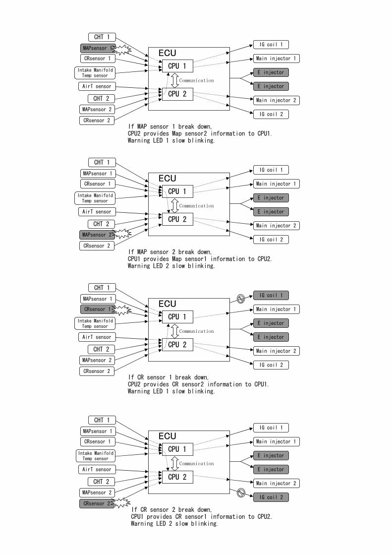
If MAP sensor 1 break down,CPU2 provides Map sensor2 information to CPU1.Warning LED 1 slow blinking.
If MAP sensor 2 break down,CPU1 provides Map sensor1 information to CPU2.Warning LED 2 slow blinking.
If CR sensor 1 break down,CPU2 provides CR sensor2 information to CPU1.Warning LED 1 slow blinking.
If CR sensor 2 break down, CPU1 provides CR sensor1 information to CPU2. Warning LED 2 slow blinking.
ECU
CPU 2
Communication
CPU 1
CHT 1
MAPsensor 1
CRsensor 1
CHT 2
MAPsensor 2
CRsensor 2
Intake ManifoldTemp sensor
AirT sensor
Main injector 1
E injector
E injector
IG coil 2
IG coil 1
Main injector 2
ECU
CPU 2
Communication
CPU 1
CHT 1
MAPsensor 1
CRsensor 1
CHT 2
MAPsensor 2
CRsensor 2
Intake ManifoldTemp sensor
AirT sensor
Main injector 1
E injector
E injector
IG coil 2
IG coil 1
Main injector 2
ECU
CPU 2
Communication
CPU 1
CHT 1
MAPsensor 1
CRsensor 1
CHT 2
MAPsensor 2
CRsensor 2
Intake ManifoldTemp sensor
AirT sensor
Main injector 1
E injector
E injector
IG coil 2
IG coil 1
Main injector 2
ECU
CPU 2
Communication
CPU 1
CHT 1
MAPsensor 1
CRsensor 1
CHT 2
MAPsensor 2
CRsensor 2
Intake ManifoldTemp sensor
AirT sensor
Main injector 1
E injector
E injector
IG coil 2
IG coil 1
Main injector 2

If intake manifold temp sensor break down,Both CPUs work by standard temperature data.Warning LED 1 slow blinking.
If out air temp sensor break down,Both CPUs work by standard temperature data.Warning LED 2 slow blinking.
If IG coil 1 break down,Both CPUs work continue and engine running by only IG coil 2.Warning LED 1 slow blinking.
If IG coil 2 break down,Both CPUs work continue and engine running by only IG coil 1.Warning LED 2 slow blinking.
ECU
CPU 2
Communication
CPU 1
CHT 1
MAPsensor 1
CRsensor 1
CHT 2
MAPsensor 2
CRsensor 2
Intake ManifoldTemp sensor
AirT sensor
Main injector 1
E injector
E injector
IG coil 2
IG coil 1
Main injector 2
ECU
CPU 2
Communication
CPU 1
CHT 1
MAPsensor 1
CRsensor 1
CHT 2
MAPsensor 2
CRsensor 2
Intake ManifoldTemp sensor
AirT sensor
Main injector 1
E injector
E injector
IG coil 2
IG coil 1
Main injector 2
ECU
CPU 2
Communication
CPU 1
CHT 1
MAPsensor 1
CRsensor 1
CHT 2
MAPsensor 2
CRsensor 2
Intake ManifoldTemp sensor
AirT sensor
Main injector 1
E injector
E injector
IG coil 2
IG coil 1
Main injector 2
ECU
CPU 2
Communication
CPU 1
CHT 1
MAPsensor 1
CRsensor 1
CHT 2
MAPsensor 2
CRsensor 2
Intake ManifoldTemp sensor
AirT sensor
Main injector 1
E injector
E injector
IG coil 2
IG coil 1
Main injector 2
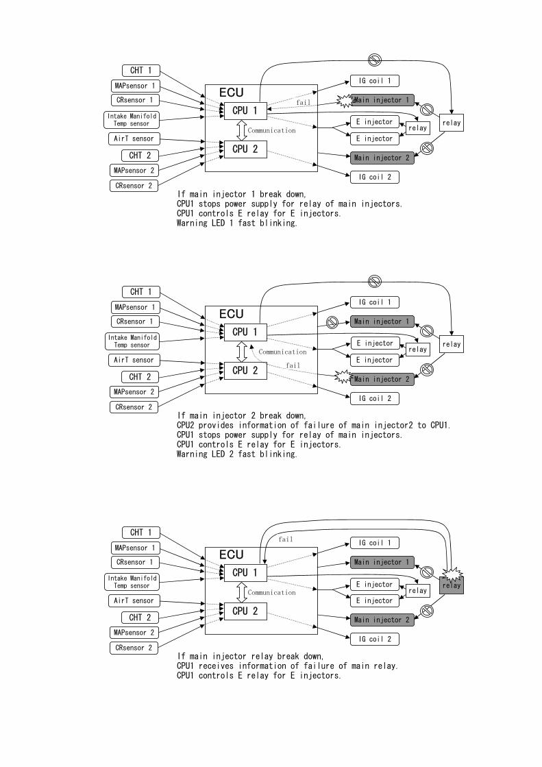
If main injector 1 break down,CPU1 stops power supply for relay of main injectors.CPU1 controls E relay for E injectors.Warning LED 1 fast blinking.
If main injector 2 break down,CPU2 provides information of failure of main injector2 to CPU1.CPU1 stops power supply for relay of main injectors.CPU1 controls E relay for E injectors.Warning LED 2 fast blinking.
If main injector relay break down,CPU1 receives information of failure of main relay.CPU1 controls E relay for E injectors.
ECU
CPU 2
Communication
CPU 1
CHT 1
MAPsensor 1
CRsensor 1
CHT 2
MAPsensor 2
CRsensor 2
Intake ManifoldTemp sensor
AirT sensor
Main injector 1
E injector
E injector
IG coil 2
IG coil 1
Main injector 2
ECU
CPU 2
Communication
CPU 1
CHT 1
MAPsensor 1
CRsensor 1
CHT 2
MAPsensor 2
CRsensor 2
Intake ManifoldTemp sensor
AirT sensor
Main injector 1
E injector
E injector
IG coil 2
IG coil 1
Main injector 2
ECU
CPU 2
Communication
CPU 1
CHT 1
MAPsensor 1
CRsensor 1
CHT 2
MAPsensor 2
CRsensor 2
Intake ManifoldTemp sensor
AirT sensor
Main injector 1
E injector
E injector
IG coil 2
IG coil 1
Main injector 2
fail
fail
relayrelay
relayrelay
relayrelay
fail

Emergency function
System operation at normal condition
Each cylinder is controlled independently by ECU
System operation during malfunction
During malfunction
Function LED1 LED2 Emergency function
CHT1 ON Temperature information of CHT2 is supplied to CHT1.
CHT2 ON Temperature information of CHT1 is supplied to CHT2.
MAP sensor1 ON Pressure information of MAP sensor2 is supplied to MAP sensor1.
MAP sensor2 ON Pressure information of MAP sensor1 is supplied to MAP sensor2.
CR sensor1 ON
CR sensor2 ON
InManiT sensor ON Controlled with the standard temperature.
AT sensor ON As it is not used for engine management, there is no affection.
IG coil 1 ON Controlled with IG coil 2 only.
IG coil 2 ON Controlled with IG coil 1 only.
Injector1 ON ON Injectors of both cylinders are changed to E Injector.
Injector2 ON ON Injectors of both cylinders are changed to E Injector.
BCV ON The maximum manifold pressure will be 78kpa (Gauge pressure).
Relay 1 The Main Injector will be off and it is operated by E Injector.
Relay 2
fuse 61 ON IGSW will be off and it is operated by E Injector and IG coil 2.
fuse 62 ON IGSW2 will be off and it is operated by E Injector and IG coil 1.
fuse 65 ON ON
fuse 66 ON ON
fuse 67
fuse 26 Fastblink
fuse 60Fastblink
fuse 63 ON ON
fuse 64
fuse 70
When CHT is increased abnormally, only fuel injection amount of the cylinder thathad a trouble will be compensated.
Injector1 will be off and Injectors of both cylinders are changed to E Injector.
Injector2 will be off and Injectors of both cylinders are changed to E Injector.
Constant power supply from battery to ECU1 will be off. Although ECU cannot memorize errorinformation, engine can be operated.
If one of the functions is lost, by communication between ECU1 and ECU2,the lost function will be compensated and the engine does not stop.
Constant power supply from battery to ECU2 will be off. Although ECU cannot memorize errorinformation, engine can be operated.
In case one of ECU has an error, engine will be operated with information supplied from the other ECU. The ECUthat had an error just stops control but power supply to ECU unit is not cut.
If plural different functions are lost, by communication between ECU1 and ECU2, the lost functions will becovered each other and the engine does not stop.
Although starter motor does not work, engine can be operated.
Information of CR sensor2 is supplied to ECU1 and Injector1 keeps working. IG coil1 isstopped.
Information from CR sensor1 is supplied to ECU2 and Injector2 keeps working. IG coil2 isstopped.
It is power supply for Relay 2. Main Injector will be off. It is operated by E Injector.
E Injector will be off. As E Injector is not used for normal operation, there is noaffection.
E Injector will be off. As E Injector is not used for normal operation, there is noaffection.
It is power supply for Relay 1. Main Injector will be off. It is operated by E Injector.