Embed Size (px)
Citation preview

ULT FreezerModel 5700 Series Chest FreezerManual Number 7005708 Rev. 15
VWR InternationalVWR International
MANUAL NUMBER 7005708
15 23939 5/29/07 Added note - adjust LN2 tank pressure relief valve to 30 PSI maximum blow-off ccs
-- 24100 5/29/07 Clarified battery switch to Standby mode with symbol ccs
14 23859/FR-1940 12/4/06 Clarified BUS install (probe/solenoid harness) instructions ccs
13 23700/Fr-1919 10/09/06 Updated safety temp specs (from 5° - 40°C to 5° - 43°C) ccs
12 23579/FR-1911 8/18/06 Corrected start capacitor part number on electrical schematic ccs
11 23170 2/13/06 Remote alarm connector is customer installed aks
10 23062 12/30/05 Changed display boards for 3 and 6.7 cu. ft. models aks
-- 22930 12/30/05 WEEE Directive aks
9 22895 8/17/05 Removed rotalock valves from compressors aks
8 22676 5/23/05 Changed control panel alarm indicators aks
7 22562 3/7/05 Modified software to allow alarms within 5C of set point aks
-- 22769 3/7/05 Changed circuit and breaker requirements for 5708 and 5710 aks
6 22362 9/27/04 Changed micro board aks
5 22136 5/6/04 Revised electrical schematics aks
4 22179/22216 3/16/04 Revised electrical schematics aks
3 21800 9/16/03 Revised refrigeration schematics aks
2 21795 8/15/03 Revised BUS operation instructions aks
1 21605 5/27/03 Wrong power alarm modifications aks
-- 21526 5/27/03 Solenoid valve mounting bracket aks
0 -- 3/12/03 Original Manual aks
REV ECR/ECN DATE DESCRIPTION By
Preface
7005708 i
Models Capacity inCubic Feet Voltage
5708 3 120
5709 3 230
5710 6.7 120
5711 6.7 230
5712 12.7 230
5715 12.7 120
5718 17 120
5719 17 230
5720 20 230
5721 20 120
Models Covered

VWR Internationalii 7005708 VWR International
Preface
Important Read this instruction manual. Failure to read, understand and follow the instructions in this manualmay result in damage to the unit, injury to operating personnel, and poor equipment performance. ▲
Caution All internal adjustments and maintenance must be performed by qualified service personnel. ▲
Material in this manual is for information purposes only. The contents and the product it describes are subject tochange without notice. VWR International makes no representations or warranties with respect to this manual.In no event shall VWR be held liable for any damages, direct or incidental, arising out of or related to the use ofthis manual.
© 2003 Thermo Fisher Scientific. All rights reserved.
Part Number Description Quantity
34040 Key Ring 1
213F Key 2
380520 Neoprene Cap 2
510016 1/4-20 x 5-1/2” Bolt 2
402058 Vacu-Key 1
195763 Retaining Clip 1
370563 Remote Alarm Connector 1
Packing List

VWR International 7005708 iiiVWR International
Preface
Important operating and/or maintenance instructions. Read the accompanying text carefully.
Potential electrical hazards. Only qualified persons should perform procedures associated with thissymbol.
Equipment being maintained or serviced must be turned off and locked off to prevent possible injury.
Hot surface(s) present which may cause burns to unprotected skin, or to materials which may bedamaged by elevated temperatures.
Marking of electrical and electronic equipment, which applies to electrical and electronic equipmentfalling under the Directive 2002/96/EC (WEEE) and the equipment that has been put on the marketafter 13 August 2005.
This product is required to comply with the European Union’s Waste Electrical & ElectronicEquipment (WEEE) Directive 2002/96/EC. It is marked with the WEEE symbol. Thermo hascontracted with one or more recycling/disposal companies in each EU Member State EuropeanCountry, and this product should be disposed of or recycled through them. Further information onThermo’s compliance with this directive, the recyclers in your country and information on ThermoFisher Scientific products will be available at www.thermofisher.com.
✔ Always use the proper protective equipment (clothing, gloves, goggles, etc.)
✔ Always dissipate extreme cold or heat and wear protective clothing.
✔ Always follow good hygiene practices.
✔ Each individual is responsible for his or her own safety.

VWR Internationaliv 7005708 VWR International
Preface
Do You Need Information or Assistance on VWR Scientific Products?
The VWR can provide information on pricing and give you quotations. We can take your order and provide delivery information on major equipment items or make arrangements to have your local sales representative contact your. Our products are listed on the internet and we can be contacted through our Internet home page.
1-800-932-5000 VWR, Toll Free, UShttp://www.vwrsp.com Internet Worldwide Web Home page
The VWR can supply technical information about proper setup, operation or troubleshooting of your equipment. We can fill your needs for replacement parts or provide you with on-site service. We can also provide you with a quotation on our Extended Maintenance Program for your Forma products.
Whatever VWR or Forma products you need or use, we will be happy to discuss your applications. If you are experiencing technical problems, working together, we will help you locate the problem and, chances are, correct it yourself...over the telephone without a service call.
When more extensive service is necessary, we will assist you with direct factory trained technicians or a qualified service organization for on-the-spot repair. If your service need is covered by the VWR Brand warranty, we will arrange for the unit to be repaired at our expense and to your satisfaction.
Regardless of your needs, VWR support by Forma's professional telephone technicians is available to assist you Monday through Friday from 8:00a.m. to 6:30 p.m. Eastern Time. Please call or fax us at:
If you wish to write, our mailing address is:
Thermo Fisher Scientific401 Millcreek Road, Box 649Marietta, OH 45750
Sales Group
Product Service Group at Forma
1-740-373-4763 Direct1-888-213-1790 Toll Free, U.S. and Canada1-740-373-4189 FAXhttp://www.thermo.com/forma Internet Worldwide Web Home Page
Service E-Mail [email protected]

7005708 vVWR International
Table of Contents
Installation and Start-up . . . . . . . . . . . . . . . . . . . . . . . . . . . . . . . . . . . . .1 - 1Control Panel Keys, Displays, Indicators . . . . . . . . . . . . . . . . . . . .1 - 5Operation of the Keypad . . . . . . . . . . . . . . . . . . . . . . . . . . . . . . . .1 - 6Install Freezer . . . . . . . . . . . . . . . . . . . . . . . . . . . . . . . . . . . . . . . . .1 - 6
Choose Location . . . . . . . . . . . . . . . . . . . . . . . . . . . . . . . . . . . . .1 - 6Install Wall Bumpers . . . . . . . . . . . . . . . . . . . . . . . . . . . . . . . . . . .1 - 7Remote Alarm Contacts . . . . . . . . . . . . . . . . . . . . . . . . . . . . . . . .1 - 7Attach Power Cord . . . . . . . . . . . . . . . . . . . . . . . . . . . . . . . . . . .1 - 8Connect Unit to Electrical Power . . . . . . . . . . . . . . . . . . . . . . . . .1 - 8
Freezer Start-Up . . . . . . . . . . . . . . . . . . . . . . . . . . . . . . . . . . . . . . .1 - 9Set Operating Temperature . . . . . . . . . . . . . . . . . . . . . . . . . . . . .1 - 9Set High Temperature Alarm . . . . . . . . . . . . . . . . . . . . . . . . . . . .1 -10Set Low Temperature Alarm . . . . . . . . . . . . . . . . . . . . . . . . . . . . .1 -10
Run Mode . . . . . . . . . . . . . . . . . . . . . . . . . . . . . . . . . . . . . . . . . . . .1 -11
Calibrate . . . . . . . . . . . . . . . . . . . . . . . . . . . . . . . . . . . . . . . . . . . . . . . . . . .2 - 1Calibrate Mode . . . . . . . . . . . . . . . . . . . . . . . . . . . . . . . . . . . . . . . .2 - 1
Calibrate Control Probe . . . . . . . . . . . . . . . . . . . . . . . . . . . . . . . .2 - 1
Alarms . . . . . . . . . . . . . . . . . . . . . . . . . . . . . . . . . . . . . . . . . . . . . . . . . . . .3 - 1Alarms . . . . . . . . . . . . . . . . . . . . . . . . . . . . . . . . . . . . . . . . . . . . . .3 - 1Wrong Power Alarm . . . . . . . . . . . . . . . . . . . . . . . . . . . . . . . . . . . .3 - 1High Stage System Failure . . . . . . . . . . . . . . . . . . . . . . . . . . . . . . . .3 - 2Probe Failure Alarm . . . . . . . . . . . . . . . . . . . . . . . . . . . . . . . . . . . .3 - 2Voltage Compensation Alarm . . . . . . . . . . . . . . . . . . . . . . . . . . . . .3 - 2
Maintenance . . . . . . . . . . . . . . . . . . . . . . . . . . . . . . . . . . . . . . . . . . . . . . .4 - 1Clean Cabinet Exterior . . . . . . . . . . . . . . . . . . . . . . . . . . . . . . . . . .4 - 1Clean Air Filter . . . . . . . . . . . . . . . . . . . . . . . . . . . . . . . . . . . . . . . .4 - 1Clean Condenser . . . . . . . . . . . . . . . . . . . . . . . . . . . . . . . . . . . . . . .4 - 1
Clean Water-cooled Condenser . . . . . . . . . . . . . . . . . . . . . . . . . . .4 - 2Defrost Chamber . . . . . . . . . . . . . . . . . . . . . . . . . . . . . . . . . . . . . .4 - 2Clean Lid Gasket . . . . . . . . . . . . . . . . . . . . . . . . . . . . . . . . . . . . . .4 - 3Replace Battery(s) . . . . . . . . . . . . . . . . . . . . . . . . . . . . . . . . . . . . . .4 - 3Prepare Unit for Storage . . . . . . . . . . . . . . . . . . . . . . . . . . . . . . . . . .4 - 5Preventive Maintenance . . . . . . . . . . . . . . . . . . . . . . . . . . . . . . . . .4 - 6
Section 1
Section 2
Section 3
Section 4

vi 7005708 VWR International
Factory Options . . . . . . . . . . . . . . . . . . . . . . . . . . . . . . . . . . . . . . . . . . . . .5 - 1BUS (Back Up System) . . . . . . . . . . . . . . . . . . . . . . . . . . . . . . . . . .5 - 1
Install Injection Assembly . . . . . . . . . . . . . . . . . . . . . . . . . . . . . . .5 - 1Install Temperature Probe . . . . . . . . . . . . . . . . . . . . . . . . . . . . . . .5 - 2Connect Probe/Solenoid Harness . . . . . . . . . . . . . . . . . . . . . . . . .5 - 4BUS Control Panel . . . . . . . . . . . . . . . . . . . . . . . . . . . . . . . . . . . .5 - 4Configure Optional BUS . . . . . . . . . . . . . . . . . . . . . . . . . . . . . . .5 - 5Set Optional BUS Set Point . . . . . . . . . . . . . . . . . . . . . . . . . . . . .5 - 6Disconnect Fitting Assembly, Transfer Hose . . . . . . . . . . . . . . . . .5 - 6
Chart Recorder . . . . . . . . . . . . . . . . . . . . . . . . . . . . . . . . . . . . . . . .5 - 7Install Chart Paper . . . . . . . . . . . . . . . . . . . . . . . . . . . . . . . . . . . .5 - 7Recorder Calibration . . . . . . . . . . . . . . . . . . . . . . . . . . . . . . . . . . .5 - 7
Datalogger . . . . . . . . . . . . . . . . . . . . . . . . . . . . . . . . . . . . . . . . . . .5 - 8Water-cooled Condenser . . . . . . . . . . . . . . . . . . . . . . . . . . . . . . . . .5 - 9
Specifications . . . . . . . . . . . . . . . . . . . . . . . . . . . . . . . . . . . . . . . . . . . . . .6 - 1
Spare Parts . . . . . . . . . . . . . . . . . . . . . . . . . . . . . . . . . . . . . . . . . . . . . . . . .7 - 1
Refrigeration Schematics . . . . . . . . . . . . . . . . . . . . . . . . . . . . . . . . . . . .8 - 1
Electrical Schematics . . . . . . . . . . . . . . . . . . . . . . . . . . . . . . . . . . . . . . .9 - 1
Warranty . . . . . . . . . . . . . . . . . . . . . . . . . . . . . . . . . . . . . . . . . . . . . . . . . .10 - 1
Handling Liquid Nitrogen . . . . . . . . . . . . . . . . . . . . . . . . . . . . . . . . . . . .A - 1
Handling Liquid CO2 . . . . . . . . . . . . . . . . . . . . . . . . . . . . . . . . . . . . . . . . .B - 1
First Aid . . . . . . . . . . . . . . . . . . . . . . . . . . . . . . . . . . . . . . . . . . . . . . . . . . . .C - 1
Table of Contents
Section 5
Section 6
Section 8
Section 7
Section 9
Section 10
Appendix B
Appendix A
Appendix C

7005708 1-1VWR International
Section 1 Installation and Start-up
Figures 1-1 and 1-2 show the front view of the freezer and indicate thefollowing freezer components:
• Control Panel - keypad, displays and indicators
• BUS (Optional Back Up System) panel
• Optional temperature recorder (7 day, one pen) or datalogger
• Key lock - keyed lid lock
Figure 1-1. Front View Models 5708, 5709, 5710, 5711
Figure 1-2. Front View Models 5712, 5715, 5718, 5719, 5720, 5721

1-2 7005708 VWR International
Section 1Installation and Start-up
Figures 1-3 and 1-4 display the rear view of the freezer and indicate thefollowing freezer components:
• Remote alarm contacts.
• Power inlet for power cord connection.
• Optional BUS connections for probe and solenoid.
• Power Switch (mains disconnect).
Figure 1-3. Rear View Models 5708, 5709, 5710, 5711
Figure 1-4. Rear View Models 5712, 5715, 5718, 5719, 5720, 5721

7005708 1-3VWR International
Section 1Installation and Start-up
The probe cover houses the control, optional recorder, datalogger, 1535alarm, or BUS probes.
Figures 1-6, 1-7, and 1-8 indicate the following components:
• Freezer filter location.
• Battery power switch (freezer and BUS).
• Thermocouple receptacle.
• Battery mounting bracket .
• Freezer and optional BUS battery.
Figure 1-5. Probe Cover
Figure 1-6. 12.7,17,20 cu.ft. Freezer Models 5712, 5715, 5718, 5719, 5720, 5721

1-4 7005708 VWR International
Section 1Installation and Start-up
Figure 1-7. Freezer Left Side - Sidecar panel removed
Figure 1-8. 3, 6.7 cu. ft. Freezers - Models 5708, 5709, 5710, 5711

1. Temperature Display - Displays temperature in degrees Celsius.
2. Mode Select Switch - Used to select Run, Set Temperature, Set HighAlarm, Set Low Alarm, Calibrate, Backup.
3. Alarm Indicator - Light pulses on/off during an alarm condition of thecabinet.
4. Mute - Silences the audible alarm.
5. Alarm Panel - Indicates the current alarm condition.
6. Up and Down Arrows - Increases or decreases values, toggles betweenchoices.
7. Enter - Stores the value into memory.
7005708 1-5VWR International
Section 1Installation and Start-up
Control Panel Keys,Display, Indicators
Figure 1-9. Control Panel Keys, Display and Indicators

The Model 5700 Series freezer has five basic modes which allow freezersetup and operation. Press the Mode key to scroll through the modeselections.
Up Arrow: Increases or toggles the parameter value.
Enter: Must press Enter key to save to memory allchanged values.
Down Arrow: Decreases or toggles the parameter value.
Mute Key: Press to silence the audible alarm. See Section 4for alarm ringback times.
Note If tipped more than 45°, allow the unit to set upright for 24 hoursbefore start up. ▲
To remove the freezer from the pallet, use a 7/16" wrench to remove all thebolts securing the shipping bracket to the pallet.
Remove the shipping bracket. Remove the ramp boards from the pallet andplace the slotted end over the ramp brackets on the pallet. The supportblocks on the ramps will be facing down. Before moving the freezer, makesure the casters are unlocked and moving freely. Align the caster with theramp boards. Use adequate personnel to roll the freezer off the pallet.
The freezer can be easily pushed to the desired approved location,described in the following section. When the freezer is in position, set thefront caster brakes.
Note The freezer must not be moved with the product load inside. ▲
Locate the freezer on a firm, level surface in an area with an ambienttemperature between 18°C and 32°C. Provide ample room to reach themains disconnect switch (power switch) located on the rear of the freezer.
Note For proper ventilation and airflow, a minimum clearance of 5” at therear and front and a clearance of 8” on the side of the freezer is required.Allow adequate space for lid opening. If ambient increases above 36°C,clearance at the rear of the cabinet must be increased to 8”. ▲
1-6 7005708 VWR International
Section 1Installation and Start-up
Operation of theKeypad
Install Freezer
Choose Location

The parts bag, located inside the cabinet, contains the following parts.
Install the bolts into the pre-tapped holes on the back of the freezer. Installa neoprene cap on each bolt. Refer to Figures 1-3 and 1-4 for the locationsof the pre-tapped holes.
See Figures 1-3 and 1-4 for the location of the remote alarm contacts. Theremote alarm connector is located in the parts bag provided with themanual. It must be installed if connecting the freezer to an alarm system.After installing the wiring from the alarm system to the connector, installthe connector to the freezer microboard and secure with the two screwsprovided. The remote alarm provides a NO (normally open) output, a NCnormally closed) output and COM (common). The contacts will trip on apower outage, high temperature alarm or low temperature alarm. Figure1-10 shows the remote contacts in alarm state.
7005708 1-7VWR International
Section 1Installation and Start-up
Install Wall BumpersQuantity Stock # Description Purpose
2 510016 1/4-20 x 5-1/2” Bolt Wall Bumper
2 380520 Neoprene Cap Cap Protector
Remote Alarm Contacts
Figure 1-10. Remote Alarm Contacts

Insert the power cord into the power inlet module. Place the retainingbracket (P/N 195763) over the connector. Tighten retaining screws tosecure.
Note See the serial tag on the side of the unit for electrical specifications orrefer to the electrical schematics in this manual. ▲
The freezer should be operated on a dedicated grounded service. Check thevoltage rating on the serial tag of the unit and compare it with the outletvoltage. Then, with the power switch turned off, plug the line cord intothe wall outlet.
First, turn on the freezer power switch. Then open the lower front door bygrasping the bottom left corner. Locate the battery switch (Figures 1-3 and1-4.) and turn it to Standby mode ( ). During initial freezer start-up, thesystem battery may require charging and the Low Battery message mayappear in the message center.
Note Ensure the battery switch is turned to Standby mode ( ). Therechargeable batteries require 36 hours to charge at initial start-up. A “LowBattery” alarm may occur until the batteries are fully charged. Should apower failure occur during the initial start-up period, the electronics willhave limited operation. ▲
1-8 7005708 VWR International
Section 1Installation and Start-up
Attach Power Cord
Figure 1-11. Power Cord Retaining Bracket
Connect Unit to ElectricalPower

With the freezer properly installed and connected to power, system setpoints can be entered. The following set points can be entered in Settingsmode: Control temperature, high temperature alarm set point, lowtemperature alarm set point, and (optional) BUS set point. Default settingsare shown below.
Note If the set point is changed and the low temperature and hightemperature alarms are set 10° from the set point, the alarm set points willbe adjusted automatically to maintain a distance of at least 10° from setpoint. ▲
The freezer has an operating temperature range of -50°C to -86°C,depending on ambient temperature. The freezer is shipped from thefactory with a temperature set point of -80°C. To change the operatingtemperature set point:
1. Press the Mode key until the Set Temperature indicator lights.
2. Press the up/down arrow key until the desired temperature set point isdisplayed.
3. Press Enter to save the set point.
4. Press the Mode key until the Run indicator lights for Run mode
If no keys are pressed, the freezer will automatically return to Run modeafter 5 minutes.
7005708 1-9VWR International
Section 1Installation and Start-up
Control Set Point -80°C
High Temperature Alarm -70°C
Low temperature alarm -90°C
Optional BUS Set Point -60°C
Freezer Start-Up
Set Operating Temperature

The high temperature alarm activates an audible/visual warning when thefreezer chamber temperature has reached or exceeded the high temperaturealarm set point.
To set the high temperature alarm set point:
1. Press the Mode key until the Set High Alarm indicator lights.
2. Press the up or down arrow key until the desired high temperaturealarm set point is displayed.
3. Press Enter to save the setting.
4. Press the Mode key until the Run indicator lights for Run mode.
If no control keys are pressed, the freezer automatically returns to Runmode after 5 minutes.
Note The high alarm set point must be set at least 5°C from the controlset point. ▲
Note At initial start-up, the high temperature alarm is disabled until thecabinet reaches set point, or 12 hours elapse. ▲
The low temperature alarm activates an audible/visual warning when thefreezer chamber temperature has reached or decreased below the lowtemperature alarm set point.
To set the low temperature alarm set point:
1. Press the Mode key until the Set Low Alarm indicator lights.
2. Press the up or down arrow key until the desired low temperaturealarm set point is displayed.
3. Press Enter to save the setting.
4. Press the Mode key until the Run indicator lights for Run mode.
If no control keys are pressed, the freezer will automatically return to Runmode after 5 minutes.
Note The low alarm set point must be set at least 5°C from the control setpoint. ▲
1-10 7005708 VWR International
Section 1Installation and Start-up
Set High TemperatureAlarm
Set Low TemperatureAlarm

Run mode is the default mode for the freezer. Run mode displays thecabinet temperature on the temperature display under normal operatingconditions. In addition, the Run mode allows the high stage heat exchangetemperature to be displayed.
This information is scrolled by pressing the up or down arrow keys. Thedisplay returns to the operating temperature in 10 seconds if no keys arepressed.
7005708 1-11VWR International
Section 1Installation and Start-up
Run Mode


7005708 2-1VWR International
Section 2 Calibrate
Once the freezer has stabilized, the control probe may need to becalibrated. Calibration frequency is dependent on use, ambient conditionsand accuracy required. A good laboratory practice would require at least anannual calibration check. On new installations, all parameters should bechecked after the stabilization period.
Before making any calibration or adjustments to the unit, it is imperativethat all reference instruments be properly calibrated.
Plug a type T thermocouple reader into the receptacle located inside thelower door (see Figures 1-4 and 1-6). Compare the control temperatureset point to the temperature of the measuring device.
1. Press the Mode key until the Calibrate indicator lights.
2. Press up/down arrow to match the display to calibrated instrument.
3. Press Enter to store calibration.
4. Press the Mode key to return to Run mode.
Startup - Allow 12 hours for the temperature in the cabinet to stabilizebefore proceeding.
Already Operating - Allow at least 2 hours after the display reaches setpoint for temperature to stabilize before proceeding.
Note During calibration, the temperature display will not be available. ▲
If no keys are pressed for approximately 5 minutes while in calibrationmode, the system will reset to Run mode.
Calibrate Mode
Calibrating the ControlProbe
Temperature Stabilization Periods


7005708 3-1VWR International
Section 3 Alarms
The Model 5700 Series freezer alarms are displayed on the control panel.When an alarm is active, the indicator next to the alarm description lightsand an audible alarm sounds. Press the Mute key to silence the audiblealarm for the ringback period. The visual alarm continues until the freezerreturns to a normal condition. The alarms are momentary alarms only.When an alarm condition occurs and then returns to normal, the freezerautomatically clears the alarm condition.
The Wrong Power alarm occurs when incorrect voltage is applied to thefreezer. If a 230V freezer is connected to a 120V power source or a 120Vfreezer is connected to a 230V power source, the electronics detect that a"Wrong Power" has been applied. Under this condition, the fans andcompressors will not turn on and an audible and visual alarm occur.
This alarm may also occur if the battery switch is turned on prior toapplying power to the freezer. The audible and visual alarms remain untilthe freezer is connected to the correct power source. The audible alarmcannot be silenced under this condition.
Description Delay Ringback Relay
Power Failure 1 min. 15 min. Yes
High Temperature Alarm 1 min. 15 min. Yes
Low Temperature Alarm 1 min. 15 min. Yes
Probe Failure - see Probe Failure Alarm section 1 min. 15 min. No
Door Open 1 min. 15 min. No
Wrong Power 0 min. none Yes
Low Battery* 1 min. 12 hours No
Hot Condenser 1 min. none No
High Stage Failure 0 min. 15 min. Yes
All alarm delays and ringback times are ±30 seconds. * The automatic battery test runs 12 hours after initial start-up, then every 12 hours thereafter.
Wrong Power
Alarms
3-2 7005708 VWR International
Section 3Alarms
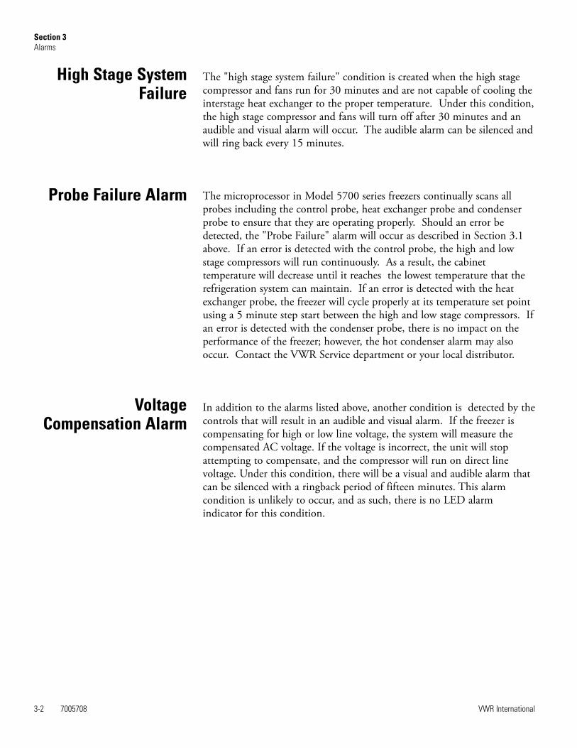
The "high stage system failure" condition is created when the high stagecompressor and fans run for 30 minutes and are not capable of cooling theinterstage heat exchanger to the proper temperature. Under this condition,the high stage compressor and fans will turn off after 30 minutes and anaudible and visual alarm will occur. The audible alarm can be silenced andwill ring back every 15 minutes.
The microprocessor in Model 5700 series freezers continually scans allprobes including the control probe, heat exchanger probe and condenserprobe to ensure that they are operating properly. Should an error bedetected, the "Probe Failure" alarm will occur as described in Section 3.1above. If an error is detected with the control probe, the high and lowstage compressors will run continuously. As a result, the cabinettemperature will decrease until it reaches the lowest temperature that therefrigeration system can maintain. If an error is detected with the heatexchanger probe, the freezer will cycle properly at its temperature set pointusing a 5 minute step start between the high and low stage compressors. Ifan error is detected with the condenser probe, there is no impact on theperformance of the freezer; however, the hot condenser alarm may alsooccur. Contact the VWR Service department or your local distributor.
In addition to the alarms listed above, another condition is detected by thecontrols that will result in an audible and visual alarm. If the freezer iscompensating for high or low line voltage, the system will measure thecompensated AC voltage. If the voltage is incorrect, the unit will stopattempting to compensate, and the compressor will run on direct linevoltage. Under this condition, there will be a visual and audible alarm thatcan be silenced with a ringback period of fifteen minutes. This alarmcondition is unlikely to occur, and as such, there is no LED alarmindicator for this condition.
Probe Failure Alarm
VoltageCompensation Alarm
High Stage SystemFailure

7005708 4-1VWR International
Section 4 Maintenance
Wipe down the freezer exterior using soap and water and a general uselaboratory disinfectant. Rinse thoroughly with clean water and dry with asoft cloth.
Caution Avoid the excessive use of water around the control area due tothe risk of electrical shock. Damage to the controls may also result. ▲
The air filter should be cleaned a minimum of four times per year.
1. Open the front door by grasping the handle.
2. Locate the grille on the door. See Figure 1-4. Grasp the middle of thegrille material and gently pull out to remove.
3. Wash the filter material using water and a mild detergent.
4. Dry by pressing between two towels.
5. Install the filter back into the grille and close the door.
Depending upon environmental conditions, the filter may need to becleaned or replaced more frequently. If the filter becomes torn orexcessively dirty, a replacement can be purchased from VWR. Order partnumber 760211 for 3.0 and 6.7 cu. ft. units or 760212 for 12, 17, and 20cu. ft. units.
The condenser should be cleaned a minimum of once per year.
1. Open the front door by grasping the handle. See Figure 1-4.
2. Using a vacuum cleaner, exercising care to not damage the condenserfins, clean the condenser.
Depending upon environmental conditions, the condenser may need to becleaned more frequently.
Clean Cabinet Exterior
Clean Air Filter
Clean Condenser

4-2 7005708 VWR International
Section 4Maintenance
The water-cooled condenser can be cleaned-in-place by using the CIPprocedure. Cleaning solutions can be used, depending on type of depositsor build-up to be removed.
Do not use liquids that are corrosive to stainless steel or the brazingmaterial (copper or nickel).
1. Disconnect the unit from the water supply.
2. Drain the unit.
3 . Rinse with fresh water and drain the unit again.
4. Fill with fresh water.
5. Add cleaning agent (solution and concentration dependent on depositsor build-up).
6. Circulate cleaning solution (if feasible).
7. Drain the cleaning solution.
8. Add and circulate a passivating liquid for corrosion inhibition of platesurfaces.
9. Drain this liquid.
10. Rinse with fresh water and drain.
11. Reconnect the water supply and fill the unit.
12 . Return to service.
1. Remove all product and place it in another freezer.
2. Turn the unit off and disconnect it from the power source.
3. Turn off the battery switch (see figures 4-1 and 4-2).
4. Open the lid and remove sub-lids. Place towels on the chamber floor.
5. Allow the frost to melt and become loose. Remove it with a soft cloth.
Clean Water-cooledCondenser
CIP (Clean-In-Place)Procedure
Defrost Chamber

7005708 4-3VWR International
Section 4Maintenance
7. After defrosting is complete, clean the interior with a non-chloridedetergent. Rinse thoroughly with clean water and dry with a soft cloth.
8. Plug unit in and turn power switch on.
9. Turn the battery power switch to the on position.
10. Allow the freezer to operate empty overnight before reloading theproduct.
The lid gasket should be cleaned a minimum of once per month.
Using a soft cloth, remove any frost build-up from the gasket, sub-lids andlids. The lid gasket may need to be cleaned more frequently if dirt orexcessive frost build-up prevents the door from closing properly.
The following instructions describe the battery replacement procedure forspecific models.
1. Open the front door by grasping on the handle and pulling.
2. Locate the battery power switch (Figure 4-1). Turn the battery powerswitch to the Off position.
3. Remove the four screwsholding the recorder bezelto gain access to thebattery.
4. Remove the three nutssecuring the batterybracket See figure 4-1.
5. Remove the bracket andold battery. Dispose ofproperly. Install the newbattery and secure.
6. Reconnect the battery (redto positive and black to negative).
Clean Lid Gasket
Replace Battery(s)
Models 5712, 5715, 5718,5719, 5720, 5721
Figure 4-1. Battery and Switch location
Defrost Chamber(continued)

7. Replace the recorder bezel.
8. Turn on the battery power switch.
9. Close lower panel door.
1. Open the front door by grasping the handle and pulling.
2. Locate the battery power switch (Figure 4-2). Turn the battery powerswitch to the off position.
3. Remove the two nuts securing the battery bracket. See Figure 4-2.
5. Remove the bracket and old battery. Dispose of properly. Install thenew battery and secure.
6. Reconnect the battery (red to positive and black to negative).
7. Replace the recorder bezel.
8. Turn on the battery power switch.
9. Close lower panel door.
Note For a consistent and dependable charge, replace the battery every 2years. Replacement batteries must be rechargeable and are available fromVWR. Refer to the parts list for stock number and description of thereplacement batteries (part number 400159). Dispose of the used batteriesin a safe manner and in accordance with good environmental practices. ▲
4-4 7005708 VWR International
Section 4Maintenance
Models 5708, 5709, 5710,5711
Figure 4-2. Battery and Switch location

Defrost the unit as previously described. This prepares the unit for storage.Turn off the battery power switch. Turn off the freezer power switch.
If the unit has been in service, turn it off and disconnect the power cordconnector before proceeding with any maintenance.
7005708 4-5VWR International
Section 4Maintenance
Prepare Unit forStorage

4-6 7005708 VWR International
Section 4Maintenance
* Qualified service technicians only** Dispose of properly, according to all state and federal regulations.
PREVENTIVE MAINTENANCEFreezers
Your equipment has been thoroughly tested and calibrated before shipment. Regular preventive maintenance is important to keep yourunit functioning properly. The operator should perform routine cleaning and maintenance on a regular basis. For maximumperformance and efficiency, it is recommended that the unit be checked and calibrated periodically by a qualified service technician.
The following is a condensed list of preventive maintenance requirements. See the specified section of the instruction manual forfurther details.
We have qualified service technicians, using NIST traceable instruments, available in many areas. For more information on PreventiveMaintenance or Extended Warranties, please contact the VWR Service Department.
Cleaning and calibration adjustment intervals are dependent upon use, environmental conditions and accuracy required.
Tips:
• Fill an upright by starting at the bottom near the probe and add racks to one shelf at a time. Allow freezer to recover to set pointbetween shelves.
• Fill a chest by starting at the left side near the probe. Filling with room temperature racks will result in a long pull-down time.
• Fill unit with frozen product to help overall performance; frozen water jugs, for example.
• Always make certain the vacuum relief port is free of frost and ice, to allow for timely re-entry into the freezer after a door opening.
Action Monthly Yearly Every 2 Years
Verify ambient temperature, <90°F ✔
* Adjust door handle for firm latching, as needed ✔
Check and clean probe cover, gaskets, hinges and lid(s) of ice and snow. SeeFigure 1-4 for probe location. See “Clean Lid Gasket”.
✔
More frequent cleaning may berequired, depending on use andenvironmental conditions.
Check air filter. Clean or replace as needed. See “Clean Air Filter”. ✔
Check alarm back-up battery. See “Connect Unit to Electrical Power” inSection 1 and “Replace Battery” in Section 4.
✔ **Replace
Check condenser fan motor for unusual motor noise or vibration. ✔
* Verify and document calibration, at the minimum, annually. See Section 2Calibration.
* Clean condenser compartment and wipe off condenser. See “CleanCondenser” in Section 4.
✔

7005708 5-1VWR International
Section 5 Factory Installed Options
Note Before installation of BUS components, make sure the power to thefreezer is disconnected, the battery switch is turned off and the freezer haswarmed to ambient temperature. ▲
The built-in BUS (back up system) will keep the freezer chambertemperature below the critical level in the event of a power or equipmentfailure. If power to the freezer fails, or temperature increases to the back upalarm set point, the BUS injects liquefied gas into the chamber to keep thechamber temperature within the specified range.
The BUS operates on an internal 12-volt, rechargeable battery which iskept charged during normal operation by the integral battery charger.
1. Locate the mounting hole for installing the injection tee assembly. SeeFigure 5-1.
Note Cover open end of injection assembly with tape to keep insulationfrom entering nipple. ▲
2. Slide 3/8” flatwasher over open end of nipple.
3. Insert covered end of injection assembly through exterior hole.
4. Remove the tape covering the end of the nipple and install the 1/8”NPT brass tee on the open end of the nipple. Place Permagum sealantbetween the brass tee and the interior top.
BUS - Back Up System
Install Injection Assembly
Figure 5-1. Mounting location

5-2 7005708 VWR International
Section 5Factory Installed Options
5. Go to the interior and seal around the injection assembly withPermagum.
6. Install the transfer hose connecting one end to the injection assembly,the other end to the solenoid valve. Install the solenoid valve to thesupply source. The solenoid mounting bracket is not required and maybe discarded.
Note When selecting a CO2 supply cylinder, it must be equipped with asiphon tube. ▲
1. Plug the solenoid/probe connector into the BUS connection. Loop theprobe wire back into the base/side car. Secure the connector with ascrew on the ends of the connector. The connector is keyed.
2. Route the temperature probe through the probe port. The probe port islocated in the upper right corner (viewed from the side) of 12.7 and 20cu. ft. models, and in the lower right corner (viewed from the back) of3.0 and 6.7 cu. ft. models.
3. Carefully remove the existing Permagum sealant from around the probeport opening.
Figure 5-2. Injection Assembly
Install Temperature Probe
Figure 5-3. Probe and Solenoid Connections
Install Injection Assembly

4. Open the freezer lid and locate the probe cover on the upper front leftwall. Remove the two Phillips head screws securing the probe cover(see Figure 5-5).
5. Route the BUS probe through the probe port, approximately 12”.Secure the back-up probe to the temperature probe using a small tiewrap (Figure 5-5).
6. Seal around the interior and exterior opening of the probe port withPermagum sealant.
7. Reinstall the probe cover (Figure 5-5).
7005708 5-3VWR International
Section 5Factory Installed Options
Figure 5-4. Probe Access Port
Figure 5-5. Probe location
Install Temperature Probe(continued)

1. Carefully coil the extra probe lead in the compressor compartment,and secure it to the compartment wall with a tie wrap and tie wrapanchor provided. Additional tie wraps and anchors may be used tosecure the probe lead to the exterior back wall of the freezer.
2. Loosen the terminal screws on the solenoid. Slide the spade lugconnectors under the screws and tighten to secure.
3. Connect power to the freezer. Turn the freezer On, with battery switchOff (O).
a. The Solenoid Engaged light on the BUS control panel willilluminate (no injection occurs). This light stays on until the unitis below BUS setpoint.
b. The Low Battery indicator may also illuminate.
4. Turn the battery switch to Standby mode ( ) to charge both batteries.
The following section describes the configuration and operation of theBUS.
Warning When activated, this unit injects liquid nitrogen or carbondioxide. Liquid Nitrogen can cause serious freezing (frostbite) if it comesin contact with unprotected skin or eyes. Nitrogen suppresses oxygenlevels and may cause suffocation if area is not well ventilated. Refer toAppendix A for the proper handling of liquid LN2. ▲
Caution Adjust the pressure relief valve on any LN2 tank to 30 PSImaximum blow-off. ▲
Warning Carbon dioxide gas suppresses oxygen levels and may causesuffocation if area is not well ventilated. Refer to “Handling Liquid CO2 inAppendix B of this manual. ▲
5-4 7005708 VWR International
Section 5Factory Installed Options
Connect Probe/SolenoidHarness
BUS Control Panel

Power - indicates the unit has AC power.
Low Battery - battery charge is low. The battery needs replaced orrecharged.
Solenoid Engaged - BUS has opened the solenoid so it can inject gas(CO2 or LN2).
Press-To-Test - Activates the solenoid and injects LN2 or CO2 into thefreezer chamber as long as the button is depressed. The solenoid engagedindicator should light. If the Low Battery indicator lights during the test,replace the BUS battery.
Note The solenoid will not engage if lid is open. ▲
The optional BUS can be configured for LN2 or CO2 supply.
To select the supply type:
1. Press the Mode key until the Backup indicator lights.
2. Press the up or down arrow key. The display will show OP1 for CO2selection and OP2 for LN2 selection.
3. Press Enter to save the setting.
4. Press the Mode key until the Run indicator lights for Run mode
If no control keys are pressed, the freezer will automatically return to Runmode after 5 minutes.
7005708 5-5VWR International
Section 5Factory Installed Options
Figure 5-6. BUS Control Panel
Configure Optional BUS(Back Up System)
BUS Control Panel(continued)

The optional back up system is designed to inject CO2 or LN2 into thefreezer compartment if the temperature rises above back up system setpoint. To set the BUS set point:
1. Press the Mode key until the Settings indicator lights.
2. Press the right arrow until “BACKUP = -XX” is displayed in themessage center.
3. Press the up or down arrow key until the desired BUS set point isdisplayed.
4. Press Enter to save the setting.
5. Press the Mode key until the Run indicator lights or press the right orleft arrow to go to the next or previous parameter.
If no control keys are pressed, the freezer will automatically return to Runmode after 5 minutes.
Warning Changing the operating temperature set point can affect the BUSset point. The BUS set point will self adjust to maintain a temperature ofat least 10°C above the operating temperature set point. ▲
Caution The BUS set point can not be set any colder than the hightemperature alarm set point. (See Section 1 - Set High TemperatureAlarm). If the back-up system is installed with CO2, then -65°C is thecoldest BUS set point that can be used (if the cabinet set point is -75°C orcolder). ▲
To disconnect the freezer back-up from the gas supply:
1. Close the supply valve.
2. Depress the test button on the Back-Up System control box to removethe gas from the line.
3. Slowly disconnect the fitting assembly from the supply (in the eventthat any gas remains in the line).
5-6 7005708 VWR International
Section 5Factory Installed Options
Set Optional BUS SetPoint
Disconnect FittingAssembly, Transfer Hose

The following section describes the set up and operation of the optionalchart recorder.
1. Open the plastic door of the recorder and pressbutton #3 until the pen begins to move outward.
2. Unscrew the knob at the center of the chart andremove the paper.
3. Install the new chart paper, position the paper to the correct time lineand replace the knob.
4. Remove the cap from the felt pen and press button #3.
The chart recorder contains eight temperature ranges and is factory-programmed for the freezer. To change the recorder range:
1. Press and hold button #3 for one second, then let the pen move off thechart paper.
2. Press and hold for five seconds either button #1 or button #2.
3. Release the button and the green LED will begin to flash. Count thenumber of flashes to determine the present program setting.
4. To change the program setting, press the left or right arrows to increaseor decrease the count.
7005708 5-7VWR International
Section 5Factory Installed Options
Figure 5-7. Recorder Details
Chart Recorder
Install Chart Paper
Recorder Calibration

5. When the desired program numberis flashing, press button #3 to bringthe pen arm back onto the chart.Recording will begin in the newprogram.
The recorder must be in service for 24 hours before performing thefollowing calibration procedure.
1. Place an accurate thermometer in the chamber next to the recorderprobe.
2. Temperature probes for the recorder are located in the left front cornerof the freezer chamber (Figure 1-4).
3. After about three minutes, compare the thermometer reading with thechart recorder reading.
4. If an adjustment is necessary, press the #1 button to move the pen tothe left or the #2 to move the pen to the right. The button must beheld about five seconds before the pen begins to move. Release thebutton when the pen position matches the thermometer.
Note The felt-tip pen on the recorder requires periodic replacement.Usually the ink will appear to fade before replacement becomes necessary.Additional pen tips may be purchased from VWR. ▲
Dataloggers and ELPRO evaluation software provide monitoring anddocumentation of temperature and alarm conditions. The dataloggers havea memory capacity of 64,000 measured values or data points. Temperatureis measured, stored and displayed. Alarm conditions are recorded.Evaluation software permits data to be downloaded to a PC. A variety ofstatistical information is provided through calculations, analysis, graphsand printed reports. Refer to the ELPRO documentation for operatinginstructions for the datalogger.
5-8 7005708 VWR International
Section 5Factory Installed Options
Program From To
1 -40 30°C
2 0 60°C
3 -100 38°C
4 -5 50°C
5 0 100°C
6 -100 200°C
7 -115 50°C
8 -10 70°C
Calibrate Chart Recorder
Datalogger
Recorder Calibration(continued)

The water-cooled condenser (P/N 195145, 195611) is a factory installedoption and requires a qualified technician at freezer installation. Theinstallation should include proper adjustment of the regulating valve,which controls the discharge pressure. Specifications for this option aredisplayed in Table 5-1.
7005708 5-9VWR International
Section 5Factory Installed Options
Water-cooledCondenser
Water Source Tower City
Water Pressure Not to exceed 150 psig
Water Temperature Range Not to exceed 29.4C (85F)
Inlet Connection 0.5” compression
Outlet Connection 0.5” compression
Flow Rate Required 3.0 gallons (11.4 liters) per minute 1.0 gallon (3.8 liters) per minute
Drain Required No (return line is required) Yes
Table 5-1. Water Cooled Condenser Specifications

Section 6 Specifications
7005708 6-1VWR International
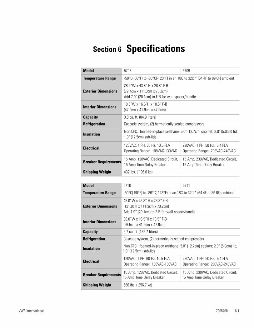
Model 5708 5709
Temperature Range -50°C(-58°F) to -86°C(-123°F) in an 18C to 32C * (64.4F to 89.6F) ambient
Exterior Dimensions28.5”W x 43.8” H x 28.8” F-B(72.4cm x 111.3cm x 73.2cm)Add 7.9” (20.1cm) to F-B for wall spacer/handle.
Interior Dimensions18.5”W x 16.5”H x 18.5” F-B(47.0cm x 41.9cm x 47.0cm)
Capacity 3.0 cu. ft. (84.9 liters)
Refrigeration Cascade system, (2) hermetically-sealed compressors
InsulationNon CFC, foamed-in-place urethane: 5.0" (12.7cm) cabinet; 2.0" (5.0cm) lid;1.0" (12.5cm) sub-lids
Electrical120VAC, 1 PH, 60 Hz, 10.5 FLAOperating Range: 108VAC-130VAC
230VAC, 1 PH, 50 Hz, 5.4 FLAOperating Range: 208VAC-240VAC
Breaker Requirements15 Amp, 120VAC, Dedicated Circuit, 15 Amp Time Delay Breaker
15 Amp, 230VAC, Dedicated Circuit,15 Amp Time Delay Breaker
Shipping Weight 432 lbs. ( 196.0 kg)
Model 5710 5711
Temperature Range -50°C(-58°F) to -86°C(-123°F) in an 18C to 32C * (64.4F to 89.6F) ambient
Exterior Dimensions48.0”W x 43.8” H x 28.8” F-B(121.9cm x 111.3cm x 73.2cm)Add 7.9” (20.1cm) to F-B for wall spacer/handle.
Interior Dimensions38.0”W x 16.5”H x 18.5” F-B(96.5cm x 41.9cm x 47.6cm)
Capacity 6.7 cu. ft. (189.7 liters)
Refrigeration Cascade system, (2) hermetically-sealed compressors
Insulation Non CFC, foamed-in-place urethane: 5.0" (12.7cm) cabinet; 2.0" (5.0cm) lid;1.0" (12.5cm) sub-lids
Electrical120VAC, 1 PH, 60 Hz, 10.5 FLAOperating Range: 108VAC-130VAC
230VAC, 1 PH, 50 Hz, 5.4 FLAOperating Range: 208VAC-240VAC
Breaker Requirements 15 Amp, 120VAC, Dedicated Circuit,15 Amp Time Delay Breaker
15 Amp, 230VAC, Dedicated Circuit,15 Amp Time Delay Breaker
Shipping Weight 566 lbs. ( 256.7 kg)

6-2 7005708 VWR International
Section 6Specifications
Model 5715 5712
Temperature Range -50°C(-58°F) to -86°C(-123°F) in an 18C to 32C * (64.4F to 89.6F) ambient
Exterior Dimensions72.0”W x 40.5” H x 28.8” F-B(182.9cm x 102.9cm x 73.2cm)Add 7.9” (20.1cm) to F-B for wall spacer/handle.
Interior Dimensions42.5”W x 28.0”H x 18.5” F-B(108.0cm x 71.1cm x 47.6cm)
Capacity 12.7 cu. ft. (360 liters)
Refrigeration Cascade system, (2) hermetically-sealed compressors
Insulation Non CFC, foamed-in-place urethane: 5.0" (12.7cm) cabinet; 2.0" (5.0cm) lid;1.0" (12.5cm) sub-lids
Electrical120VAC, 1 PH, 60 Hz, 16.0 FLAOperating Range: 108VAC-130VAC
230VAC, 1 PH, 50/60 Hz, 12.0 FLAOperating Range: 208VAC-240VAC
Breaker Requirements20 Amp, 120VAC, Dedicated Circuit,20 Amp Time Delay Breaker
15 Amp, 230VAC, Dedicated Circuit, 15 Amp Time Delay Breaker
Shipping Weight 716 lbs. (324.8 kg)
Model 5718 5719
Temperature Range -50°C(-58°F) to -86°C(-123°F) in an 18C to 32C * (64.4F to 89.6F) ambient
Exterior Dimensions87.6.0”W x 40.5” H x 28.8” F-B(222.5cm x 102.9cm x 73.2cm)Add 7.9” (20.1cm) to F-B for wall spacer/handle.
Interior Dimensions58.8”W x 28.0”H x 18.5” F-B(149.4cm x 71.1cm x 47.0cm)
Capacity 17.0 cu. ft. (481.4 liters)
Refrigeration Cascade system, (2) hermetically-sealed compressors
Insulation Non CFC, foamed-in-place urethane: 5.0" (12.7cm) cabinet; 2.0" (5.0cm) lid;1.0" (12.5cm) sub-lids
Electrical120VAC, 1 PH, 60 Hz, 16.0 FLAOperating Range: 108VAC-130VAC
230VAC, 1 PH, 50/60 Hz, 12.0 FLAOperating Range: 208VAC-240VAC
Breaker Requirements20 Amp, 120VAC, Dedicated Circuit,20 Amp Time Delay Breaker
15 Amp, 230VAC, Dedicated Circuit,15 Amp Time Delay Breaker
Shipping Weight 821 lbs. ( 372.4 kg)

7005708 6-3VWR International
Section 6Specifications
CertificationsDeclaration of Conformity is available from the factory
Safety SpecificationsIndoor Use OnlyAltitude - up to 2,000 metersTemperature - 5°C to 43°CHumidity - Maximum RH 80% for temperatures up to 31°C, decreasing linearly to 50% RH at 40°CMains Supply Fluctuations - Mains supply voltage fluctuations not to exceed ±10% of the nominal voltageInstallation Category II 1
Pollution Degree 2 2
Class of Equipment I______________________________________________________________________
1 Installation category (overvoltage category) defines the level of transient overvoltage which the instrument isdesigned to withstand safely. It depends on the nature of the electricity supply and its overvoltage protectionmeans. For example, in CAT II which is the category used for instruments in installations supplied from a supplycomparable to public mains such as hospital and research laboratories and most industrial laboratories, theexpected transient overvoltage is 2500V for a 230V supply and 1500V for a 120V supply.
2 Pollution degree describes the amount of conductive pollution present in the operating environment.Pollution degree 2 assumes that normally only non-conductive pollution such as dust occurs with the exception ofoccasional conductivity caused by condensation.
Model 5721 5720
Temperature Range -50°C(-58°F) to -86°C(-123°F) in an 18C to 32C * (64.4F to 89.6F) ambient
Exterior Dimensions96.0”W x 40.5” H x 28.8” F-B(243.8cm x 102.9cm x 73.2cm)Add 7.9” (20.1cm) to F-B for wall spacer/handle.
Interior Dimensions66.5”W x 28.0”H x 18.5” F-B(168.9cm x 71.1cm x 47.6cm)
Capacity 20.0 cu. ft. (566.3 liters)
Refrigeration Cascade system, (2) hermetically-sealed compressors
InsulationNon CFC, foamed-in-place urethane: 5.0" (12.7cm) cabinet; 2.0" (5.0cm) lid;1.0" (12.5cm) sub-lids
Electrical120VAC, 1 PH, 60 Hz, 16.0 FLAOperating Range: 108VAC-130VAC
230VAC, 1 PH, 50/60 Hz, 12.0 FLAOperating Range: 208VAC-240VAC
Breaker Requirements20 Amp, 120VAC, Dedicated Circuit,20 Amp Time Delay Breaker
15 Amp, 230VAC, Dedicated Circuit, 15 Amp Time Delay Breaker
Shipping Weight 833 lbs. ( 377.8 kg)


7005708 7-1VWR International
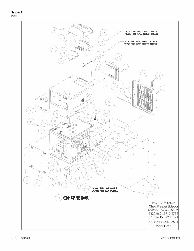
Section 7Parts
7005708 7-1

7-2 7005708 VWR International
Section 7Parts

7005708 7-3VWR International
Section 7Parts

7-47005708
VWR International
Section 7Parts

7005708 7-5VW
R International
Section 7Parts

7-6 7005708 VWR International
Section 7Parts

7005708 7-7VWR International
Section 7Parts

7-8 7005708 VWR International
Section 7Parts

7005708 7-9VWR International
Section 7Parts
7-10 7005708 VWR International
Section 7Parts
12.7, 17, 20 cu. ft
Chest Freezer Sidecar
5612,5615,5618,5619,
5620,5621,5712,5715
5718,5719,5720,5721
5615-200-2-B Rev. 1
Page 1 of 2

7005708 7-11VWR International
Section 7Parts
12.7, 17, 20 cu. ft
Chest Freezer Sidecar
5612,5615,5618,5619,
5620,5621,5712,5715
5718,5719,5720,5721
5615-200-2-B Rev. 1
Page 2 of 2
AKS

7-12 7005708 VWR International
Section 7Parts

7005708 7-13VWR International
Section 7Parts

7-14 7005708 VWR International
Section 7Parts

7005708 7-15VWR International
Section 7Parts

7-16 7005708 VWR International
Section 7Parts

7005708 7-17VWR International
Section 7Parts

7-18 7005708 VWR International
Section 7Parts

7005708 8-1VW
R International
Section 8Refrigeration Schem
atics
7005708 8-1

8-27005708
VWR International
Section 8Refrigeration Schem
atics

7005708 8-3VW
R International
Section 8Refrigeration Schem
atics

8-47005708
VWR International
Section 8Refrigeration Schem
atics

7005708 8-5VW
R International
Section 8Refrigeration Schem
atics

8-67005708
VWR International
Section 8Refrigeration Schem
atics

7005708 8-7VW
R International
Section 8Refrigeration Schem
atics


7005708 9-1VWR International
Section 9Electrical Schematics

9-2 7005708 VWR International
Section 9Electrical Schematics

7005708 9-3VWR International
Section 9Electrical Schematics


7005708 9-4VWR International
Section 9Electrical Schematics

9-5 7005708 VWR International
Section 9Electrical SchematicsSection 9Electrical Schematics

7005708 9-6VWR International
Section 9Electrical Schematics


7005708 9-7VWR International
Section 9Electrical Schematics

9-8 7005708 VWR International
Section 9Electrical Schematics

7005708 9-9VWR International
Section 9Electrical Schematics


7005708 9-10VWR International
Section 9Electrical Schematics

9-11 7005708 VWR International
Section 9Electrical Schematics

7005708 9-12VWR International
Section 9Electrical Schematics


7005708 10-1VWR International
Section 10Warranty Information
7005708 10-1
VW
R S
CIE
NT
IFIC
PR
OD
UC
TS
STA
ND
AR
D A
ND
SIG
NA
TU
RE
SE
RIE
S U
LT
FR
EE
ZE
R W
AR
RA
NT
Y-
US
A
Th
e W
arr
an
ty P
erio
d s
tart
s t
wo
we
eks f
rom
th
e d
ate
yo
ur
eq
uip
me
nt
is s
hip
pe
d f
rom
ou
r fa
cili
ty.
Th
is a
llow
s f
or
sh
ipp
ing
tim
e
so
th
e w
arr
an
ty w
ill g
o in
to e
ffe
ct
at
ap
pro
xim
ate
ly t
he
sa
me
tim
e y
ou
r e
qu
ipm
en
t is
de
live
red
. T
he
wa
rra
nty
pro
tectio
n
exte
nd
s t
o a
ny s
ub
se
qu
en
t o
wn
er
du
rin
g t
he
wa
rra
nty
pe
rio
d.
Du
rin
g t
he
first
two
ye
ars
of
the
wa
rra
nty
pe
rio
d,
co
mp
on
en
t pa
rts p
rove
n t
o b
e n
on
-co
nfo
rmin
g in
ma
teria
ls o
r w
ork
ma
nsh
ip
will
be
re
pa
ire
d o
r re
pla
ce
d a
t V
WR
/Th
erm
o E
lectr
on
Co
rpo
ratio
n’s
exp
en
se
, la
bo
r in
clu
de
d.
Th
e S
ign
atu
re S
erie
s U
LT
Fre
eze
rs in
clu
de
an
ad
ditio
na
l th
ree
ye
ar
wa
rra
nty
on
th
e c
om
pre
sso
rs,
pa
rts o
nly
, F.O
.B.
facto
ry.
Insta
llatio
n a
nd
ca
libra
tio
n
is n
ot
co
ve
red
by t
his
wa
rra
nty
ag
ree
me
nt.
Th
e T
ech
nic
al S
erv
ice
s D
epa
rtm
en
t m
ust
be
co
nta
cte
d f
or
wa
rra
nty
de
term
ina
tio
n
an
d d
ire
ctio
n p
rio
r to
an
y w
ork
be
ing
pe
rfo
rme
d.
Exp
en
da
ble
ite
ms,
i.e
., g
lass,
filte
rs,
pilo
t lig
hts
, lig
ht
bu
lbs a
nd
do
or
ga
s-
ke
ts a
re e
xclu
de
d f
rom
th
is w
arr
an
ty.
Re
pla
ce
me
nt
or
repa
ir o
f co
mp
on
en
t pa
rts o
r e
qu
ipm
en
t u
nd
er
this
wa
rra
nty
sh
all
no
t e
xte
nd
th
e w
arr
an
ty t
o e
ith
er
the
eq
uip
me
nt
or
to t
he
co
mp
on
en
t pa
rt b
eyo
nd
th
e o
rig
ina
l tw
o y
ea
r w
arr
an
ty p
erio
d.
VW
R a
nd
/or
Th
erm
o m
ust
giv
e p
rio
r
ap
pro
va
l fo
r th
e r
etu
rn o
f a
ny c
om
po
ne
nts
or
eq
uip
me
nt.
TH
IS W
AR
RA
NT
YIS
EX
CL
US
IVE
AN
D I
N L
IEU
OF
AL
LO
TH
ER
WA
RR
AN
TIE
S,
WH
ET
HE
R W
RIT
TE
N,
OR
AL
, O
R
IMP
LIE
D.
NO
WA
RR
AN
TIE
S O
F M
ER
CH
AN
TA
BIL
ITY
OR
FIT
NE
SS
FO
R A
PA
RT
ICU
LA
R P
UR
PO
SE
SH
AL
LA
PP
LY.
Th
erm
o s
ha
ll n
ot
be
lia
ble
fo
r a
ny in
dire
ct
or
co
nse
qu
en
tia
l d
am
ag
es in
clu
din
g,
with
ou
t lim
ita
tio
n,
da
ma
ge
s r
ela
tin
g t
o lo
st
pro
fits
or
loss o
f p
rod
ucts
.
Yo
ur
loca
l V
WR
Sa
les O
ffic
e is r
ea
dy t
o h
elp
with
co
mp
reh
en
siv
e s
ite
pre
pa
ratio
n in
form
atio
n b
efo
re y
ou
r e
qu
ipm
en
t a
rriv
es.
Prin
ted
in
str
uctio
n m
an
ua
ls c
are
fully
de
tail
eq
uip
me
nt
insta
llatio
n,
op
era
tio
n,
an
d p
reve
ntive
ma
inte
na
nce
.
If e
qu
ipm
en
t se
rvic
e is r
eq
uire
d,
ple
ase
ca
ll th
e T
ech
nic
al S
erv
ice
s O
ffic
e a
t 1
-88
8-2
13
-17
90
(U
SA
an
d C
an
ad
a)
or
1-7
40
-37
3-4
76
3.
We
're
re
ad
y t
o a
nsw
er
yo
ur
qu
estio
ns o
n e
qu
ipm
en
t w
arr
an
ty,
op
era
tio
n,
ma
inte
na
nce
, se
rvic
e,
an
d s
pe
cia
l
ap
plic
atio
ns.
Ou
tsid
e t
he
US
A,
co
nta
ct
yo
ur
loca
l d
istr
ibu
tor
for
wa
rra
nty
in
form
atio
n.
ISO
9001
REGIST
ERED
Re
v. 4
5
/8/0
3

10-2 7005708 VWR International
Section 11Warranty Information
10-2 7005708
VW
R S
CIE
NT
IFIC
PR
OD
UC
TS
STA
ND
AR
D A
ND
SIG
NA
TU
RE
SE
RIE
S U
LT
FR
EE
ZE
R W
AR
RA
NT
Y-
INT
ER
NA
TIO
NA
L
Th
e W
arr
an
ty P
erio
d s
tart
s t
wo
mo
nth
s f
rom
th
e d
ate
yo
ur
eq
uip
me
nt
is s
hip
pe
d f
rom
ou
r fa
cili
ty.
Th
is a
llow
s f
or
sh
ipp
ing
tim
e s
o t
he
wa
rra
nty
will
go
in
to e
ffe
ct
at
ap
pro
xim
ate
ly t
he
sa
me
tim
e y
ou
r e
qu
ipm
en
t is
de
live
red
. T
he
wa
rra
nty
pro
tectio
n
exte
nd
s t
o a
ny s
ub
se
qu
en
t o
wn
er
du
rin
g t
he
wa
rra
nty
pe
rio
d.
Du
rin
g t
he
first
two
ye
ars
of
the
wa
rra
nty
pe
rio
d,
co
mp
on
en
t pa
rts p
rove
n t
o b
e n
on
-co
nfo
rmin
g in
ma
teria
ls o
r w
ork
ma
nsh
ip
will
be
re
pa
ire
d o
r re
pla
ce
d a
t V
WR
/Th
erm
o E
lectr
on
Co
rpo
ratio
n's
exp
en
se
, la
bo
r e
xclu
de
d.
Th
e S
ign
atu
re S
erie
s U
LT
Fre
eze
rs in
clu
de
an
ad
ditio
na
l th
ree
ye
ar
wa
rra
nty
on
th
e c
om
pre
sso
rs,
pa
rts o
nly
, F.O
.B.
facto
ry.
Insta
llatio
n a
nd
ca
libra
tio
n
is n
ot
co
ve
red
by t
his
wa
rra
nty
ag
ree
me
nt.
Th
e T
ech
nic
al S
erv
ice
s D
epa
rtm
en
t m
ust
be
co
nta
cte
d f
or
wa
rra
nty
de
term
ina
tio
n
an
d d
ire
ctio
n p
rio
r to
an
y w
ork
be
ing
pe
rfo
rme
d.
Exp
en
da
ble
ite
ms,
i.e
., g
lass,
filte
rs,
pilo
t lig
hts
, lig
ht
bu
lbs a
nd
do
or
ga
ske
ts
are
exclu
de
d f
rom
th
is w
arr
an
ty.
Re
pla
ce
me
nt
or
repa
ir o
f co
mp
on
en
t pa
rts o
r e
qu
ipm
en
t u
nd
er
this
wa
rra
nty
sh
all
no
t e
xte
nd
th
e w
arr
an
ty t
o e
ith
er
the
eq
uip
me
nt
or
to t
he
co
mp
on
en
t pa
rt b
eyo
nd
th
e o
rig
ina
l tw
o y
ea
r w
arr
an
ty p
erio
d.
VW
R a
nd
/or
Th
erm
o m
ust
giv
e p
rio
r
ap
pro
va
l fo
r th
e r
etu
rn o
f a
ny c
om
po
ne
nts
or
eq
uip
me
nt.
TH
IS W
AR
RA
NT
YIS
EX
CL
US
IVE
AN
D I
N L
IEU
OF
AL
LO
TH
ER
WA
RR
AN
TIE
S,
WH
ET
HE
R W
RIT
TE
N,
OR
AL
, O
R
IMP
LIE
D.
NO
WA
RR
AN
TIE
S O
F M
ER
CH
AN
TA
BIL
ITY
OR
FIT
NE
SS
FO
R A
PA
RT
ICU
LA
R P
UR
PO
SE
SH
AL
LA
PP
LY.
Th
erm
o s
ha
ll n
ot
be
lia
ble
fo
r a
ny in
dire
ct
or
co
nse
qu
en
tia
l d
am
ag
es in
clu
din
g,
with
ou
t lim
ita
tio
n,
da
ma
ge
s r
ela
tin
g t
o lo
st
pro
fits
or
loss o
f p
rod
ucts
.
Yo
ur
loca
l V
WR
Sa
les O
ffic
e is r
ea
dy t
o h
elp
with
co
mp
reh
en
siv
e s
ite
pre
pa
ratio
n in
form
atio
n b
efo
re y
ou
r e
qu
ipm
en
t a
rriv
es.
Prin
ted
in
str
uctio
n m
an
ua
ls c
are
fully
de
tail
eq
uip
me
nt
insta
llatio
n,
op
era
tio
n,
an
d p
reve
ntive
ma
inte
na
nce
.
If e
qu
ipm
en
t se
rvic
e is r
eq
uire
d,
ple
ase
ca
ll yo
ur
loca
l d
istr
ibu
tor
or
the
Te
ch
nic
al S
erv
ice
s D
epa
rtm
en
t a
t 1
-74
0-3
73
-47
63
(1-8
88
-21
3-1
79
0 in
US
Ao
r C
an
ad
a).
We
're
re
ad
y t
o a
nsw
er
yo
ur
qu
estio
ns o
n e
qu
ipm
en
t w
arr
an
ty,
op
era
tio
n,
ma
inte
na
nce
,
se
rvic
e,
an
d s
pe
cia
l a
pp
lica
tio
ns.
Ou
tsid
e t
he
US
A,
co
nta
ct
yo
ur
loca
l d
istr
ibu
tor
for
wa
rra
nty
in
form
atio
n.
ISO
9001
REGIST
ERED
Re
v. 5
5/8
/03

VWR International
Appendix A Handling Liquid Nitrogen
Warning Contact of liquid nitrogen or cold gas with the skin or eyes maycause serious freezing (frostbite) injury. ▲
Handle liquid nitrogen carefully.
The extremely low temperature can freeze human flesh very rapidly. Whenspilled on a surface the liquid tends to cover it completely and intimately,cooling a large area. The gas issuing from the liquid is also extremely cold.Delicate tissue, such as that of the eyes, can be damaged by an exposure tothe cold gas which would be too brief to affect the skin of the hands orface.
Never allow any unprotected part of your body to touch objects cooledby liquid nitrogen.
Such objects may stick fast to the skin and tear the flesh when you attemptto free yourself. Use tongs to withdraw objects immersed in the liquid,and handle the object carefully.
Wear protective clothing.
Protect your eyes with a face shield or safety goggles (safety glasses withoutside shields do not give adequate protection). Always wear gloves whenhandling anything that is, or may have been, in immediate contact withliquid nitrogen. Insulated gloves are recommended, but heavy leathergloves may also be used. The gloves should fit loosely, so that they can bethrown off quickly if liquid should splash into them. When handlingliquid in open containers, it is advisable to wear high-top shoes. Trousers(which should be cuffless if possible) should be worn outside the shoes.
7005708 A -1

VWR International
Appendix AHandling Liquid NitrogenAppendix AHandling Liquid Nitrogen
A -2 7005708
The safe handling and use of liquid nitrogen in cryogenic refrigerators anddewar flasks is largely a matter of knowing the potential hazards and usingcommon-sense procedures based on that knowledge. There are twoimportant properties of liquid nitrogen that present potential hazards:
1. It is extremely cold. At atmospheric pressure, liquid nitrogen boils at -320°F (-196°C).
2. Very small amounts of liquid vaporize into large amounts of gas. Oneliter of liquid nitrogen becomes 24.6 cu. ft. (700l) of gas.
The safety precautions in this booklet must be followed to avoid potentialinjury or damage which could result from these two characteristics. Do notattempt to handle liquid nitrogen until you read and fully understand thepotential hazards, their consequences, and the related safety precautions.Keep this booklet handy for ready reference and review.
Note Because argon is an inert gas whose physical properties are very similarto those of nitrogen, the precautions and safe practices for the handling anduse of liquid argon are the same as those for liquid nitrogen. ▲
Use only containers designed for low temperature liquids.
Cryogenic containers are specifically designed and made of materials that canwithstand the rapid changes and extreme temperature differencesencountered in working with liquid nitrogen. Even these special containersshould be filled SLOWLY to minimize the internal stresses that occur whenany material is cooled. Excessive internal stresses can damage the container.
Do not cover or plug the entrance opening of any liquid nitrogenrefrigerator or dewar. Do not use any stopper or other device that wouldinterfere with venting of gas.
These cryogenic liquid containers are generally designed to operate with littleor no internal pressure. Inadequate venting can result in excessive gaspressure which could damage or burst the container. Use only the loose-fitting necktube core supplied or one of the approved accessories for closingthe necktube. Check the unit periodically to be sure that venting is notrestricted by accumulated ice or frost.
Introduction

Use proper transfer equipment.
Use a phase separator or special filling funnel to prevent splashing andspilling when transferring liquid nitrogen into or from a dewar orrefrigerator. The top of the funnel should be partly covered to reducesplashing. Use only small, easily-handled dewars for pouring liquid. Forthe larger, heavier containers, use a cryogenic liquid withdrawal device totransfer liquid from one container to another. Be sure to followinstructions supplied with the withdrawal device. When liquid cylindersor other large storage containers are used for filling, follow the instructionssupplied with those units and their accessories.
Do not overfill containers.
Filling above the bottom of the necktube (or specified maximum level) canresult in overflow and spillage of liquid when the necktube core or cover isplaced in the opening.
Never use hollow rods or tubes as dipsticks.
When a warm tube is inserted into liquid nitrogen, liquid will spout fromthe top of the tube due to gasification and rapid expansion of liquid insidethe tube.
Warning Nitrogen Gas Can Cause Suffocation Without Warning! ▲
Store and use liquid nitrogen only in a well-ventilated place.
As the liquid evaporates, the resulting gas tends to displace the normal airfrom the area. In closed areas, excessive amounts of nitrogen gas reducethe concentration of oxygen and can result in asphyxiation. Becausenitrogen gas is colorless, odorless and tasteless, it cannot be detected by thehuman senses and will be breathed as if it were air. Breathing anatmosphere that contains less than 18% oxygen can cause dizziness andquickly result in unconsciousness and death.
Note The cloudy vapor that appears when liquid nitrogen is exposed to theair is condensed moisture; not the gas itself. The issuing gas is invisible. ▲
Never dispose of liquid nitrogen in confined areas or places where othersmay enter.
Disposal of liquid nitrogen should be done outdoors in a safe place. Pourthe liquid slowly on gravel or bare earth where it can evaporate withoutcausing damage. Do not pour the liquid on pavement.
7005708 A -3VWR International
Appendix AHandling Liquid Nitrogen


7005708 B - 1VWR International
Appendix B Handling Liquid CO2
Warning High concentrations of CO2 gas can cause asphyxiation! OSHAStandards specify that employee exposure to carbon dioxide in any eight-hour shift of a 40-hour work week shall not exceed the eight-hour timeweighted average of 5000 PPM (0.5% CO2). The short term exposurelimit for 15 minutes or less is 30,000 PPM (3% CO2). Carbon dioxidemonitors are recommended for confined areas where concentrations ofcarbon dioxide gas can accumulate. ▲
Store and use liquid CO2 only in a well-ventilated place.
As the liquid evaporates, the resulting gas tends to displace the normal airfrom the area. In closed areas, excessive amounts of CO2 gas reduce theconcentration of oxygen and can result in asphyxiation. Because CO2 gasis colorless, odorless and tasteless, it cannot be detected by the humansenses and will be breathed as if it were air. Breathing an atmosphere thatcontains less than 18% oxygen can cause dizziness and quickly result inunconsciousness and death.
Note The cloudy vapor that appears when liquid CO2 is exposed to the airis condensed moisture; not the gas itself. The issuing gas is invisible. ▲
Never dispose of liquid CO2 in confined areas or places where othersmay enter.
Disposal of liquid CO2 should be done outdoors in a safe place. Pour theliquid slowly on gravel or bare earth where it can evaporate withoutcausing damage. Do not pour the liquid on pavement.

7005708 C - 1VWR International
Appendix C First Aid
If a person seems to become dizzy or loses consciousness while workingwith liquid nitrogen or carbon dioxide, move to a well-ventilated areaimmediately. If breathing has stopped, apply artificial respiration. Ifbreathing is difficult, give oxygen. Call a physician. Keep warm and atrest.
If exposed to liquid or cold gas, restore tissue to normal body temperature(98.6° F) as rapidly as possible, followed by protection of the injured tissuefrom further damage and infection. Remove or loosen clothing that mayconstrict blood circulation to the frozen area. Call a physician. Rapidwarming of the affected part is best achieved by using water at 108° F.Under no circumstance should the water be over 112° F, nor should thefrozen part be rubbed either before or after rewarming. The patient shouldneither smoke nor drink alcohol.


VWR InternationalP.O. Box 5015Bristol, CT 06011-8960