Embed Size (px)
Citation preview

7Systems Analysis and Design in a y y g
Changing World, Fifth Edition
7
Learning ObjectivesLearning Objectives
U d t d th d l d f d fi iUnderstand the models and processes of defining object-oriented requirements
Develop use case diagrams and activity diagrams
Develop system sequence diagrams
D l t t hi di t d l bj tDevelop state machine diagrams to model object behavior
Explain how UML diagrams work together to define functional requirements for the object-orientedfunctional requirements for the object-oriented approach
Systems Analysis and Design in a Changing World, 5th Edition 2

7
OverviewOverviewThe objective of requirements definition isThe objective of requirements definition is understanding – understanding the users’ needs, the business processes, and the systems to support p , y ppbusiness processes
Understand and define requirements for a newUnderstand and define requirements for a new system using object-oriented analysis models and techniquestechniques
Line between object-oriented analysis and object-oriented design is somewhat fuzzy
Iterative approach to developmentIterative approach to development
Models built in analysis are refined during design
Systems Analysis and Design in a Changing World, 5th Edition 3
7
Object Oriented RequirementsObject-Oriented Requirements
Object-oriented modeling notation is Unified Modeling Language (UML 2.0) a guage (U 0)
UML was accepted by Object Management Group p y j g p(OMG) as standard modeling technique
Purpose of Object Management Group
Promote theor and practice of object orientedPromote theory and practice of object-oriented technology for development of distributed systems
Provide common architectural framework for OO
Systems Analysis and Design in a Changing World, 5th Edition 4
7Object-Oriented Requirements ( )(continued)
Object-oriented system requirements are specifiedObject oriented system requirements are specified and documented through process of building models
Modeling process starts with identification of use cases and problem domain classes (things in users’cases and problem domain classes (things in users work environment)
Business events trigger elementary business processes (EBP) that new system must address asprocesses (EBP) that new system must address as use cases
Use cases define functional requirements
Systems Analysis and Design in a Changing World, 5th Edition 5
7Object-Oriented Requirements Models
Use case model a collection of models to captureUse case model – a collection of models to capture system requirements
fUse case diagram – identify actors and their roles and how the actor roles utilize the system
Systems sequence diagrams (SSDs) – define inputs and outputs and sequence of interactions between p quser and system for a use case
Systems Analysis and Design in a Changing World, 5th Edition 6
7Object-Oriented Requirements ( )Models (continued)
Message – the communication between objects within a use case
Domain model – describes the classes of objects and their statestheir states
State machine diagrams – describe states of each object
Systems Analysis and Design in a Changing World, 5th Edition 7
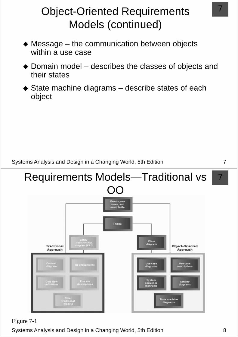
7Requirements Models—Traditional vs OOOO
Systems Analysis and Design in a Changing World, 5th Edition 8
Figure 7-1
7The System Activities—y
A Use Case/Scenario View
Use case analysis used to identify and define all business processes that system must supportbusiness processes that system must support
Use case – an activity a system carried out usually inUse case an activity a system carried out, usually in response to a user request
Actor
Role played by user
Outside automation boundary
Systems Analysis and Design in a Changing World, 5th Edition 9
7Techniques for Identifying Use Cases q y g
(Review from Chapter 5) Id tif lIdentify user goals
Each goal at the elementary business process (EBP)Each goal at the elementary business process (EBP) level is a use case
EBP – task performed by one user in one place and in response to business event that adds measurable business value, and leaves system and data in consistent state
Event decomposition technique (event table)
CRUD analysis technique (create, read/report, update, delete) to ensure coverageupdate, delete) to ensure coverage
Systems Analysis and Design in a Changing World, 5th Edition 10
7
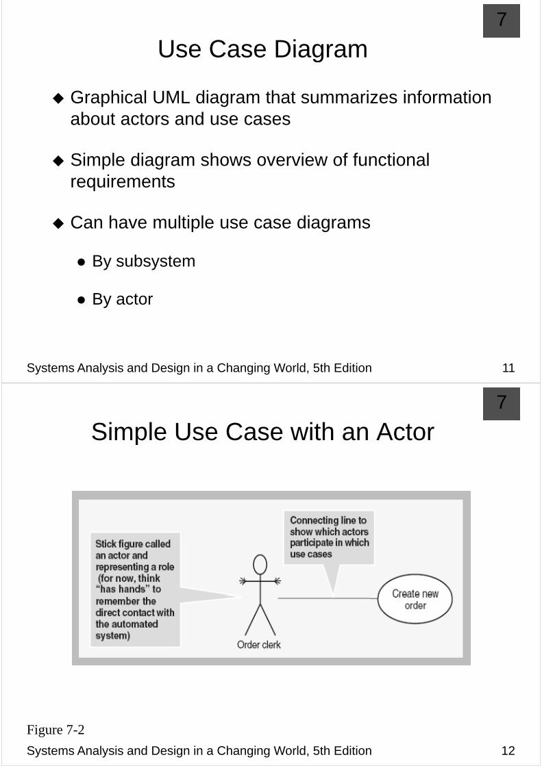
Use Case DiagramUse Case Diagram
Graphical UML diagram that summarizes information about actors and use cases
Simple diagram shows overview of functional requirements
Can have multiple use case diagrams
By subsystem
B tBy actor
Systems Analysis and Design in a Changing World, 5th Edition 11
7
Simple Use Case with an ActorSimple Use Case with an Actor
Systems Analysis and Design in a Changing World, 5th Edition 12
Figure 7-2

7Use Case Diagram with Automation Boundary and Alternate Actor Notation
Systems Analysis and Design in a Changing World, 5th Edition 13
Figure 7-3
7All Use Cases Involving Customer as Actor
Systems Analysis and Design in a Changing World, 5th Edition 14
Figure 7-4

7Use Cases of RMO Order Entry SubsystemSubsystem
Systems Analysis and Design in a Changing World, 5th Edition 15
Figure 7-5 (partial figure)
7
<<Includes>> Relationship<<Includes>> Relationship
Documents situation in which one use case requires the services of a common subroutine
Another use case is developed for this common psubroutine
A common use case can be reused by multiple use cases
Systems Analysis and Design in a Changing World, 5th Edition 16

7Example of Order-Entry Subsystem with <<Includes>> Use Cases
Systems Analysis and Design in a Changing World, 5th Edition 17
Figure 7-6
7
Developing a Use Case DiagramDeveloping a Use Case Diagram
Underlying conditions for describing use casesUnderlying conditions for describing use cases
Based on automated system, e.g. users “touch” the system
Assume perfect technology conditionAssume perfect technology condition
Iterate through these two steps
Identify actors as roles
Li t l f h t A l i itList goals, e.g. use cases, for each actor. A goal is a unit of work.
Finalize with a CRUD analysis to ensure completeness
Systems Analysis and Design in a Changing World, 5th Edition 18

7
Activity DiagramsActivity Diagrams
Used to document workflow of business process activities for each use case or scenarioactivities for each use case or scenario
Standard UML 2.0 diagram as seen in Chapter 4Standard UML 2.0 diagram as seen in Chapter 4
Can support any level of use case description; aCan support any level of use case description; a supplement to use case descriptions
Helpful in developing system sequence diagrams
Systems Analysis and Design in a Changing World, 5th Edition 19
7
Activity DiagramDiagram—Telephone p
Order S iScenario
Systems Analysis and Design in a Changing World, 5th Edition 20
Figure 7-8

7
ActivityActivity Diagram—Web Order ScenarioScenario
Systems Analysis and Design in a Changing World, 5th Edition 21
Figure 7-9
7Identifying Inputs and Outputs—The System Sequence Diagram
I t ti di i ti diInteraction diagram – a communication diagram or a sequence diagram
System sequence diagram (SSD) is type of UML 2.0 interaction diagraminteraction diagram
Used to model input and output messaging p p g grequirements for a use case or scenario
Sh f i i d iShows sequence of interactions as messages during flow of activities
System is shown as one object: a “black box”
Systems Analysis and Design in a Changing World, 5th Edition 22

7
SSD NotationSSD Notation
Lifeline or object lifeline is a ertical line nder objectLifeline or object lifeline is a vertical line under object or actor to show passage of time for object
Message is labeled on arrows to show messages sent to or received by actor or systemy y
Actor is role interacting with the system with messagesmessages
Object is the component that interacts with actors j pand other objects
Systems Analysis and Design in a Changing World, 5th Edition 23
7System Sequence Diagram (SSD) y q g ( )
Notation
Systems Analysis and Design in a Changing World, 5th Edition 24
Figure 7-10

7
SSD LifelinesSSD Lifelines
V ti l li d bj t tVertical line under object or actor
Shows passage of timeShows passage of time
If vertical line dashed
Creation and destruction of thing is not important for scenarioscenario
Long narrow rectangles
Activation lifelines emphasize that object is active only during part of scenarioduring part of scenario
Systems Analysis and Design in a Changing World, 5th Edition 25
7
SSD MessagesSSD Messages
Internal events identified by the flow of objects in a scenarioscenario
Requests from one actor or object to another to doRequests from one actor or object to another to do some action
Invoke a particular method
Systems Analysis and Design in a Changing World, 5th Edition 26

7
Repeating Message
Systems Analysis and Design in a Changing World, 5th Edition 27
Figure 7-11
7Developing a System Sequence p g y q
Diagram
Begin with detailed description of use case from fully developed form or activity diagramdeveloped form or activity diagram
Identify input messages
Describe message from external actor to system using message notationusing message notation
Identify and add any special conditions on input y y p pmessage, including iteration and true/false conditions
Identify and add output return messages
Systems Analysis and Design in a Changing World, 5th Edition 28

7Activity Diagram of the Telephone O SOrder Scenario
Systems Analysis and Design in a Changing World, 5th Edition 29
Figure 7-12
7Resulting SSD for the Telephone O SOrder Scenario
Systems Analysis and Design in a Changing World, 5th Edition 30
Figure 7-13

7
SSD of the Web OrderWeb Order Scenario
for the C tCreate
New OrderNew Order Use case
Systems Analysis and Design in a Changing World, 5th Edition 31
Figure 7-14
7Identifying Object Behavior—y g jThe State Machine Diagram
St t hi di i UML 2 0 di th tState machine diagram is UML 2.0 diagram that models object states and transitions
Complex problem domain classes can be modeled
St t f bj tState of an object
A condition that occurs during its life when it satisfies some gcriterion, performs some action, or waits for an event
Each state has unique name and is a semipermanentEach state has unique name and is a semipermanent condition or status
Transition
The movement of an object from one state to another stateThe movement of an object from one state to another state
Systems Analysis and Design in a Changing World, 5th Edition 32
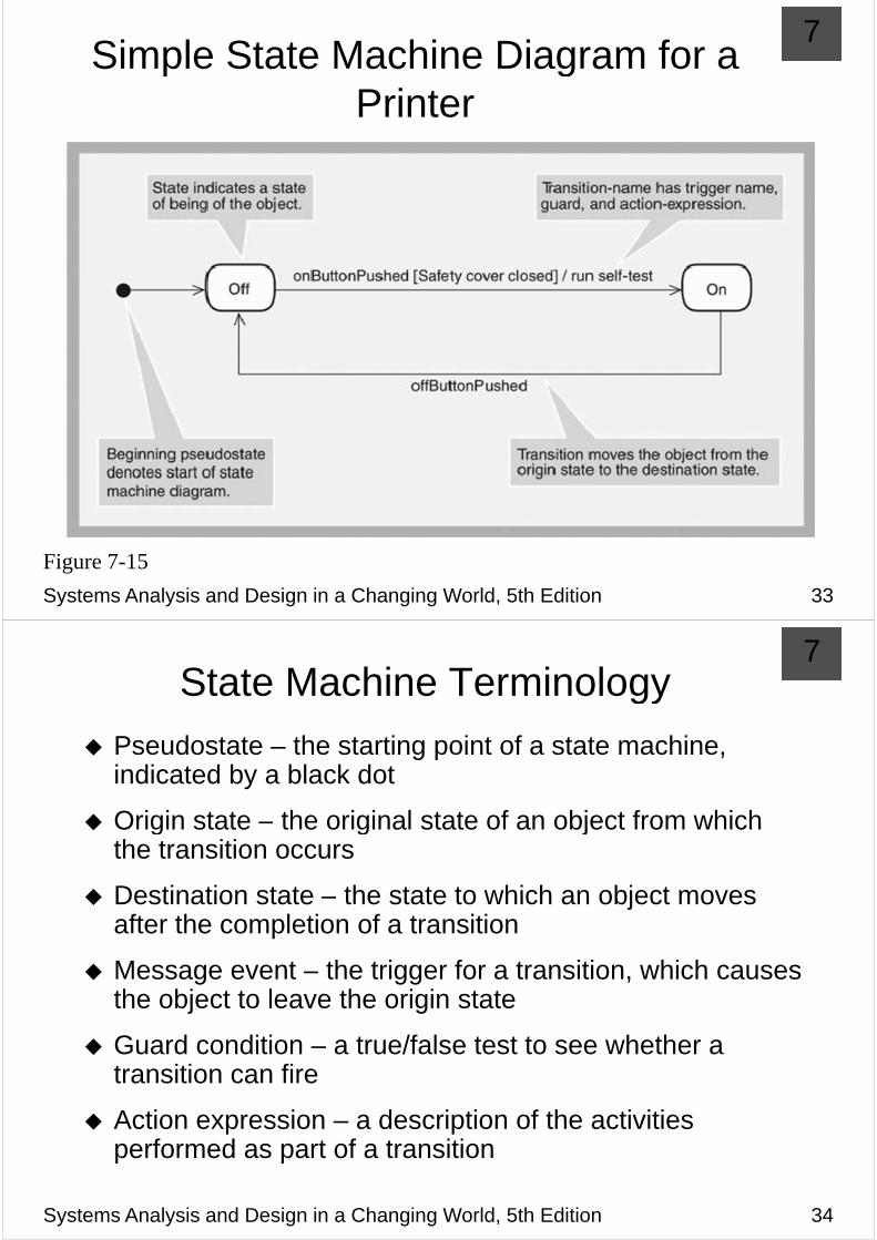
7Simple State Machine Diagram for a p g
Printer
Systems Analysis and Design in a Changing World, 5th Edition 33
Figure 7-15
7State Machine TerminologyState Machine Terminology
Pseudostate – the starting point of a state machine, indicated by a black dot
Origin state – the original state of an object from whichOrigin state the original state of an object from which the transition occurs
Destination state the state to which an object movesDestination state – the state to which an object moves after the completion of a transition
M t th t i f t iti hi hMessage event – the trigger for a transition, which causes the object to leave the origin state
Guard condition – a true/false test to see whether a transition can fire
Action expression – a description of the activities performed as part of a transition
Systems Analysis and Design in a Changing World, 5th Edition 34

7Composite States and Concurrency—p y
States within a State
Systems Analysis and Design in a Changing World, 5th Edition 35
Figure 7-16
7Concurrent Paths for Printer in the On State
Systems Analysis and Design in a Changing World, 5th Edition 36
Figure 7-17

7Rules for Developing State Machine p g
DiagramReview domain class diagram, select important ones, and list all state and exit conditions
Begin building state machine diagram fragments for h leach class
Sequence fragments in correct order and review forSequence fragments in correct order and review for independent and concurrent paths
Expand each transition with message event, guard-condition, and action-expressionp
Review and test each state machine diagram
Systems Analysis and Design in a Changing World, 5th Edition 37
7States and Exit Transitions for
OrderItem
Systems Analysis and Design in a Changing World, 5th Edition 38
Figure 7-18

7
Partial State Machine for OrderItemPartial State Machine for OrderItem
Systems Analysis and Design in a Changing World, 5th Edition 39
Figure 7-19
7
Final State Machine for OrderItemFinal State Machine for OrderItem
Systems Analysis and Design in a Changing World, 5th Edition 40
Figure 7-20
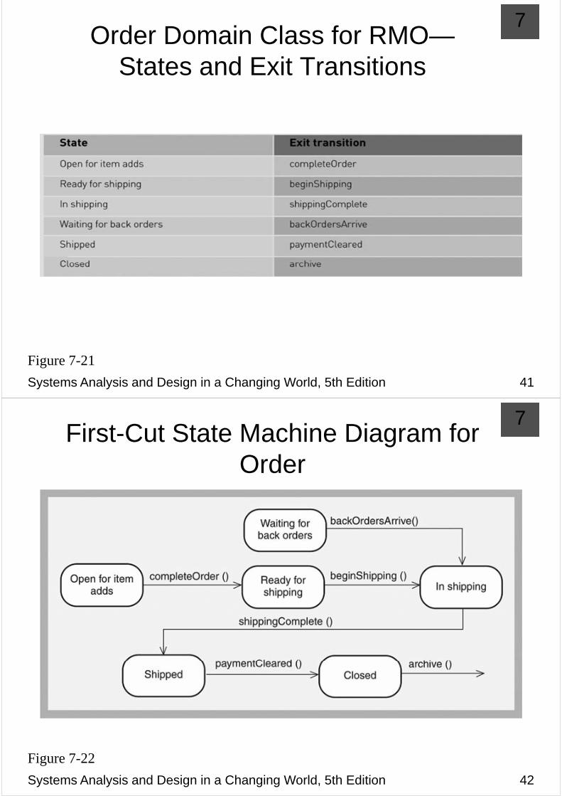
7Order Domain Class for RMO—
States and Exit Transitions
Systems Analysis and Design in a Changing World, 5th Edition 41
Figure 7-21
7First-Cut State Machine Diagram for g
Order
Systems Analysis and Design in a Changing World, 5th Edition 42
Figure 7-22

7Second-Cut State Machine Diagram for OOrder
Systems Analysis and Design in a Changing World, 5th Edition 43
Figure 7-23
7
Integrating Object Oriented ModelsIntegrating Object-Oriented Models
Complete use case diagram is needed to understand total scope of new systemtotal scope of new system
Domain model class diagrams should also be as complete as possible for entire system
With iterative approach only construct use caseWith iterative approach, only construct use case descriptions, activity diagrams, and system sequence diagrams for use cases in iterationdiagrams for use cases in iteration
Development of a new diagram often helps refine andDevelopment of a new diagram often helps refine and correct previous diagrams
Systems Analysis and Design in a Changing World, 5th Edition 44
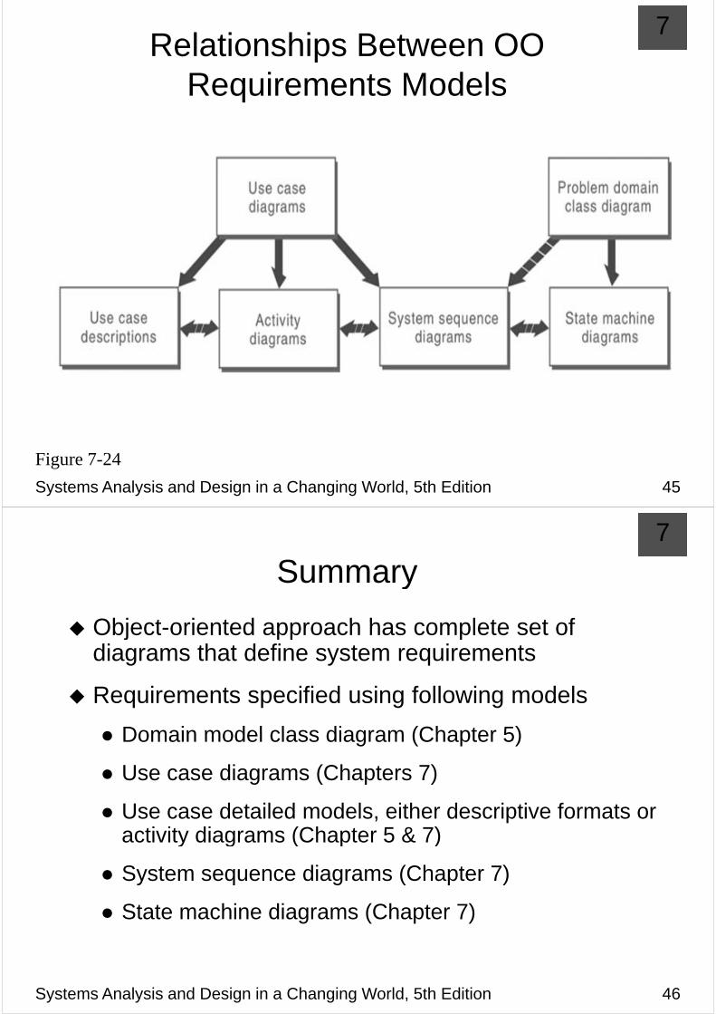
7Relationships Between OO p
Requirements Models
Systems Analysis and Design in a Changing World, 5th Edition 45
Figure 7-24
7
SummarySummary
Object oriented approach has complete set ofObject-oriented approach has complete set of diagrams that define system requirements
Requirements specified using following models
Domain model class diagram (Chapter 5)Domain model class diagram (Chapter 5)
Use case diagrams (Chapters 7)
Use case detailed models, either descriptive formats or activity diagrams (Chapter 5 & 7)activity diagrams (Chapter 5 & 7)
System sequence diagrams (Chapter 7)
State machine diagrams (Chapter 7)
Systems Analysis and Design in a Changing World, 5th Edition 46