Embed Size (px)
Citation preview

OL-19523-01
C H A P T E R 7
Enterprise WAN EdgeThe enterprise WAN edge, along with the enterprise branch, provides users at geographically disperse remote sites with access to the same rich network services as users at the main site. The availability and overall security of the WAN edge, and WAN transit, is thus critical to global business operations.
The challenge, from a security perspective, is enabling the enterprise to confidently embrace and extend these rich global services and remote collaboration capabilities to all locations. This is achieved through a defense-in-depth approach to security that extends and integrates consistent end-to-end security policy enforcement and system-wide intelligence and collaboration across the entire enterprise network.
The aim of this chapter is to illustrate the role of the enterprise WAN edge in this end-to-end security policy enforcement, including how to apply, integrate, and implement the SAFE guidelines to the WAN edge. See Figure 7-1.
Figure 7-1 Enterprise WAN Edge
Business Applications
Collaboration ApplicationsMain Enterprise Site
Private WAN
Private WAN
Enterprise WAN Edge Empowered Branches
Internet
IP
2266
62
7-1Cisco SAFE Reference Guide

Chapter 7 Enterprise WAN Edge
The focus of the enterprise WAN edge is to provide VPN access for remote sites. From a functional perspective, the enterprise WAN edge can be presented as two key areas:
• WAN edge aggregation
Performs WAN aggregation, site-to-site VPN termination, edge protection.
• WAN edge distribution
Provides connectivity to the core network, as well as the integration point for WAN edge services, such as application optimization and IPS.
Remote access, teleworker, partner, customer, and Internet access are addressed in Chapter 6, “Enterprise Internet Edge,” along with their related security guidelines.
A typical enterprise WAN edge architecture is illustrated in Figure 7-2.
Figure 7-2 Enterprise WAN Edge Functional Architecture
For more information on SAFE for the enterprise branch, see Chapter 8, “Enterprise Branch.”
M
WAN Edge AggregationEnterprise WAN Edge
2266
63
Internet
Core
WAN Edge Distribution
Management
Private WAN
Internet WAN
Private WANSP 1
Private WANSP 2
7-2Cisco SAFE Reference Guide
OL-19523-01

Chapter 7 Enterprise WAN Edge Key Threats in the Enterprise WAN Edge
Key Threats in the Enterprise WAN EdgeThe threats addressed in the WAN edge of an end-to-end enterprise architecture are focused on three key areas:
• Malicious activity initiated by branch clients, including malware proliferation, botnet detection, network and application abuse, and other malicious or non-compliant activity.
• WAN transit vulnerabilities, such as sniffing and man-in-the-middle (MITM) attacks.
• Attacks against the infrastructure itself, such as unauthorized access, privilege escalation, and denial-of-service (DoS) attacks.
Web and E-mail threats posed to branch clients, such as malicious web sites, compromised legitimate web sites, spam and phishing, are addressed in this guide by centralized web and E-mail security in the Internet edge. For more information on this area, see Chapter 6, “Enterprise Internet Edge.”
The particular threat focus of an enterprise WAN edge, and the specific security objectives and integration elements to mitigate these threats, are presented in Table 7-1.
The design and integration of each of these security elements into the WAN edge is addressed in the following sections.
Table 7-1 Key Threats in the Enterprise WAN Edge
Threat Focus Threats Mitigated Security Objectives Security Integration
Malicious branch client activity
Malware proliferation, botnets, worms, viruses, Trojans
Application and network abuse
Detect and mitigate threats
• IPS Integration
• Telemetry
WAN transit threats Unauthorized access to network and data such as through sniffing and man-in-the-middle (MITM) attacks
Isolate and secure WAN data and access
• Secure WAN Connectivity
Attacks against the infrastructure
Unauthorized access to devices, network, and data
Reconnaissance
DoS
Deliver resilient and highly available services
• Routing Security
• Service Resiliency
• Network Policy Enforcement
• Switching Security
• Secure Device Access
• Telemetry
7-3Cisco SAFE Reference Guide
OL-19523-01

Chapter 7 Enterprise WAN Edge WAN Edge Aggregation
WAN Edge AggregationThe WAN edge aggregation block serves as the hub for remote sites and performs three key roles:
• WAN aggregation
May be implemented as a private and/or an Internet WAN edge aggregation, depending on the WAN connectivity
• VPN termination
May include encryption, depending on the WAN connectivity, compliance, and customer requirements
• Edge protection
Security policy enforcement on the network border
These roles may be consolidated in a single, unified WAN services platform such as the Cisco ASR 1000 Series, or implemented on dedicated devices, as illustrated in Figure 7-3.
Figure 7-3 Enterprise WAN Edge Aggregation
WAN Edge AggregationEnterprise WAN Edge
+ +
2266
64
WAN Edge Distribution Private WAN
Internet WAN
VPNTermination
WANAggregation
Security
QFP
QFP
QFP
QFP
Internet
Private WANSP 1
Private WANSP 2
M
Management
7-4Cisco SAFE Reference Guide
OL-19523-01

Chapter 7 Enterprise WAN Edge Design Guidelines for the WAN Edge Aggregation
Design Guidelines for the WAN Edge AggregationSecurity integration in the WAN edge aggregation block includes the following elements:
• Secure WAN Connectivity in the WAN Edge, page 7-5
• Routing Security in the WAN Edge Aggregation, page 7-7
• Service Resiliency in the WAN Edge Aggregation, page 7-10
• Network Policy Enforcement in the WAN Edge Aggregation, page 7-13
• Secure Device Access in the WAN Edge Aggregation, page 7-15
• Telemetry in the WAN Edge Aggregation, page 7-16
Secure WAN Connectivity in the WAN EdgeThe WAN provides remote sites with access to centralized corporate services and business applications, as well, in many cases, Internet services. As such, it is critical to service availability and business operations. Consequently, the WAN must be properly secured to protect it against compromise, including unauthorized access, and data loss and manipulation from sniffing or MITM attacks.
The security objective is to provide confidentiality, integrity, and availability of data as it transits the WAN. The design and implementation of secure WAN connectivity is addressed as an end-to-end system, incorporating both the WAN edge and the branch. The key design recommendations and considerations presented below must be developed in conjunction with the branch WAN design and tie together to provide an end-to-end, secure WAN.
There are three key elements to consider for secure WAN connectivity:
• Isolate WAN traffic
Segment corporate WAN traffic from other traffic on the WAN to enable the confidentiality and integrity of data. This may be achieved, for example, through a dedicated point-to-point link, a corporate managed VPN, a client-originated VPN or a service provider-managed MPLS service.
• Authenticate WAN access
Access to the corporate WAN must feature a strong authentication mechanism to prevent unauthorized access to the network and data, such as a Public Key Infrastructure (PKI).
• Encrypt WAN traffic
If the WAN link is vulnerable to data loss and manipulation, or perhaps for compliance reasons, data in-transit over the WAN may need to be encrypted.
The actual adoption and implementation of each of these elements will vary depending on a number of aspects, including the WAN technology in use, customer vulnerability and risk assessment, and any particular compliance requirements. For example, if the customer is a retail store passing credit card information over the WAN, then the WAN should be highly secure and must be PCI-compliant.
In addition, service availability is a key aspect. This is addressed through service resiliency, including device hardening and redundancy. For more information on this area of security, refer to the “Service Resiliency in the WAN Edge Aggregation” section on page 7-10.
7-5Cisco SAFE Reference Guide
OL-19523-01

Chapter 7 Enterprise WAN Edge Design Guidelines for the WAN Edge Aggregation
The recommendation for secure WAN connectivity in the WAN edge includes the following:
• VPN for traffic isolation over the WAN
There are a number of VPN options and the choice will vary based on specific customer requirements. DMVPN, for instance, offers support for VPN over both a private WAN and the Internet, as well as multicast and dynamic routing. Consequently, DMVPN can be integrated to enable a common VPN implementation if both these WAN types are deployed at remote sites.
• Public Key Infrastructure (PKI) for strong tunnel authentication
PKI provides secure, scalable, and manageable authentication that is critical to large-scale VPN deployments. PKI also features the dynamic renewal and revocation of certificates that enables the dynamic commissioning and decommissioning of branches with ease.
• Advanced Encryption Standard (AES) for strong encryption
Data over the Internet is vulnerable to sniffing; therefore, encryption is critical to data confidentially and integrity. Data over a private WAN can also be encrypted for maximum security or for compliance reasons.
For more information on VPN implementation and design, refer to the WAN Design section of Appendix A, “Reference Documents.”
Note that the PKI itself must be properly secured by applying the SAFE principles to this infrastructure and services, including hardening the devices, securing access , and minimizing its exposure to risk. For more information on PKI implementation and design, refer to the WAN Design section of Appendix A, “Reference Documents.”
Technology Options
• The WAN may be delivered using a range of different technologies, depending on the customer requirements and the local service options. For more information on WAN technology options, refer to the WAN Design section of Appendix A, “Reference Documents.”
• There are a range of VPN technology options available, including DMVPN, EZPN, IPSec and GETVPN. For more information on VPN options, refer to the WAN Design section of Appendix A, “Reference Documents.”
• Pre-shared keys (PSK) may be used as an alternative tunnel authentication mechanism for smaller scale VPN deployments. PSK is simple to deploy but presents manageability challenges and its security is dependent on the strength of the defined keys. Consequently, a strong password policy must be enforced, including periodic updates. In addition, since a PSK is tied to a unique IP address, sites with a dynamically assigned IP address require the use of wild card pre-shared keys. This presents a security and operational challenge since, if the key is compromised, all spokes must be provisioned with a new key.
• Some cryptographic features are subject to additional export and contract restrictions. For more information, see the Export Restrictions section of Appendix A, “Reference Documents.”
• DES and 3DES are alternative encryption algorithms but are vulnerable to attack.
7-6Cisco SAFE Reference Guide
OL-19523-01

Chapter 7 Enterprise WAN Edge Design Guidelines for the WAN Edge Aggregation
Routing Security in the WAN Edge AggregationRouting in the WAN edge aggregation block is critical to service availability, and as such, it must be properly secured to protect it against compromise, including unauthorized peering sessions and DoS attacks that may attempt to inject false routes, and remove or modify routes.
The security of the routing is particularly important in the WAN edge, as it features a key network border, supporting both an external and an internal routing domain. Consequently, it is critical, not only that the external peering interface is properly secured, but that the routing information is properly filtered to ensure that only necessary routes are advertised out and that only valid routes are propagated into the internal routing table.
There are two routing domains to consider:
• External routing domain
Maximum routing security, including strict routing protocol membership and route redistribution filtering to ensure only the VPN hub IP address is advertised.
• Internal routing domain
Routing security for internal interfaces is typically less stringent though should, at a minimum, include neighbor authentication. In addition, route updates from the branches should be filtered to ensure only valid prefixes are distributed.
The areas of focus, objectives and implementation options for routing security in the WAN edge aggregation block are outlined in Table 7-2.
Table 7-2 Routing Security in the WAN Edge Aggregation
Routing Security Focus Routing Security Objectives Implementation
Restrict Routing Protocol Membership
Restrict routing sessions to trusted peers and validate the origin and integrity of routing updates
• Routing peer definition
• Neighbor authentication
• BGP TTL Security Hack (BTSH)
• Default passive interface
Control Route Propagations Ensure only legitimate networks are advertised and propagated
• Route redistribution filtering to only advertise the VPN hub IP address to the external routing domain
• Peer prefix filtering to only accept routes into the internal routing domain for branch subnets received over the VPN tunnel
• Maximum prefix filtering to restrict excessive route prefixes
Log Neighbor Changes Detect neighbor status changes that may indicate network connectivity and stability issues, due to an attack or general operations problems
• Neighbor logging on all routing domains
7-7Cisco SAFE Reference Guide
OL-19523-01

Chapter 7 Enterprise WAN Edge Design Guidelines for the WAN Edge Aggregation
A sample implementation of secure routing in the Internet WAN edge module is shown below and it integrates the SAFE guidelines to:
• Authenticate all routing peers.
• Only distribute the hub IP address out of the external routing domain. This is a loopback interface that is common across the hub devices.
• Disable routing on all interfaces by default.
• Explicitly enable the internal routing domain on interfaces to the WAN edge distribution switches and the VPN tunnels.
• Explicitly enable the external routing domain on interfaces to the private WAN.
• Only permit distribution into the internal routing domain of the branch subnets advertised from the tunnel interfaces.
• Enable neighbor logging on all routing domains.
! Internal Routing Domainrouter eigrp 1 network 10.56.0.0 0.0.255.255 network 10.0.0.0 no auto-summary! Only accept route updates for the branch subnets over the VPN tunnel interfaces distribute-list 30 in Tunnel0! By default disables routing on all interfaces passive-interface default! Internal routing is permitted on interfaces to the WAN edge distribution switches and the VPN tunnels no passive-interface GigabitEthernet0/0/0 no passive-interface GigabitEthernet0/0/2 no passive-interface Tunnel0! Enables neighbor logging eigrp log-neighbor-changes!! External Routing Domainrouter eigrp 100 network 192.168.0.0 0.0.255.255 no auto-summary! Only distribute the hub IP address out distribute-list DMVPNHUB out! By default disables routing on all interfaces passive-interface default! Exterbal routing is permitted on interfaces to the Private WAN no passive-interface GigabitEthernet0/0/3 no passive-interface GigabitEthernet0/0/4! Enables neighbor logging eigrp log-neighbor-changes!ip access-list standard DMVPNHUB permit 192.168.34.1!! Branch Subnets permitted into the internal routing domain from the VPN tunnelsaccess-list 30 remark Branch EIGRP Routesaccess-list 30 permit 10.200.0.0 0.0.255.255access-list 30 permit 10.201.0.0 0.0.255.255!! Authenticate internal routing peerskey chain eigrp-auth key 10 key-string <strong-key>!
7-8Cisco SAFE Reference Guide
OL-19523-01
Chapter 7 Enterprise WAN Edge Design Guidelines for the WAN Edge Aggregation
! Authenticate external routing peerskey chain eigrp-auth-egp key 11 key-string <strong-key>!interface Tunnel0 description Tunnel0 ip authentication mode eigrp 1 md5 ip authentication key-chain eigrp 1 eigrp-auth!interface Loopback0 ip address 192.168.34.1 255.255.255.255!interface GigabitEthernet0/0/0 ip authentication mode eigrp 1 md5 ip authentication key-chain eigrp 1 eigrp-auth!interface GigabitEthernet0/0/2 ip authentication mode eigrp 1 md5 ip authentication key-chain eigrp 1 eigrp-auth!interface GigabitEthernet0/0/3 description WAN: MPLS ip authentication mode eigrp 100 md5 ip authentication key-chain eigrp 100 eigrp-auth-egp!interface GigabitEthernet0/0/4 description WAN: MPLS ip authentication mode eigrp 100 md5 ip authentication key-chain eigrp 100 eigrp-auth-egp
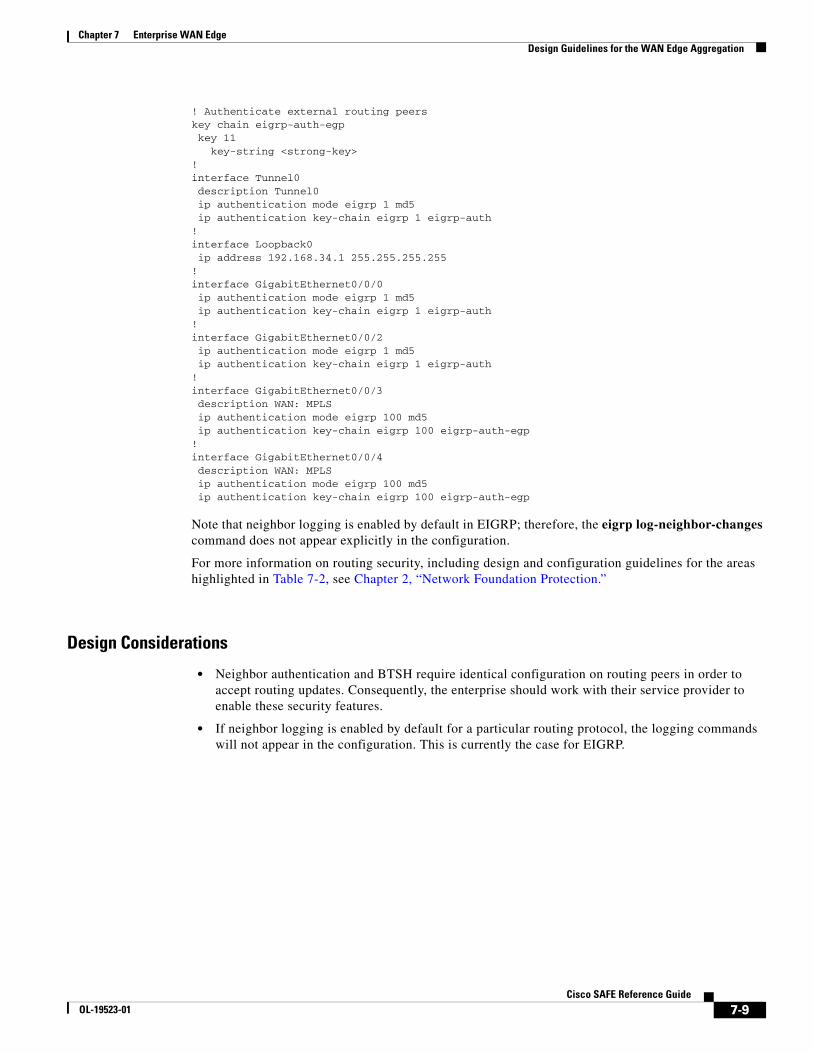
Note that neighbor logging is enabled by default in EIGRP; therefore, the eigrp log-neighbor-changes command does not appear explicitly in the configuration.
For more information on routing security, including design and configuration guidelines for the areas highlighted in Table 7-2, see Chapter 2, “Network Foundation Protection.”
Design Considerations
• Neighbor authentication and BTSH require identical configuration on routing peers in order to accept routing updates. Consequently, the enterprise should work with their service provider to enable these security features.
• If neighbor logging is enabled by default for a particular routing protocol, the logging commands will not appear in the configuration. This is currently the case for EIGRP.
7-9Cisco SAFE Reference Guide
OL-19523-01

Chapter 7 Enterprise WAN Edge Design Guidelines for the WAN Edge Aggregation
Service Resiliency in the WAN Edge AggregationThe resiliency of services provided by the WAN edge aggregation block is critical to the operation of all remote sites. The WAN edge is also a key network border. Consequently, all infrastructure devices and links must be resilient to targeted, indirect, malicious and unintentional attacks, as well as general failure scenarios. This is particularly important since the edge devices have external interfaces.
Possible attacks include DoS attacks based on unauthorized and authorized protocols, distributed DoS (DDoS) attacks, flood attacks, reconnaissance, and unauthorized access. General failure scenarios include power outages, physical link failures, and device failures.
Service resiliency in the WAN edge aggregation block involves the following key design areas:
• Device resiliency
• Remote site service availability
• High availability
The areas of focus, objectives, and implementation options for service resiliency in the WAN edge aggregation block are outlined in Table 7-3.
The particular considerations for IKE CAC and QoS in the WAN edge are covered in detail below. For more information on the other service resiliency techniques, including design and configuration guidelines, see Chapter 2, “Network Foundation Protection.”
Service resiliency should be complemented by network policy enforcement techniques that filter traffic at the network edges, permitting only authorized services and originators to directly address the infrastructure. These techniques restrict accessibility to the infrastructure in order to reduce exposure to unauthorized access, DoS, and other network attacks. For more information, refer to the “Network Policy Enforcement in the WAN Edge Aggregation” section on page 7-13.
Table 7-3 Service Resiliency in the WAN Edge Aggregation
Service Resiliency Focus Service Resiliency Objectives Implementation
Restrict attack surface Disable unnecessary services
Address known vulnerabilities
• Disable unnecessary services on all infrastructure devices
• Patch infrastructure devices with updated software
Harden the device Protect device resources from exhaustion attacks by limiting, filtering and rate-limiting traffic destined to the control plane.
• Memory protection
• Limit and rate-limit control plane traffic, including service-specific considerations (for example, IKE CAC)
• Implement CoPP/CoPPr, if available
Preserve and optimize remote site services
Ensure any limited resources at a remote site, such as a low bandwidth WAN link or a low performance platform, are not overwhelmed, and optimize their utilization.
• QoS—Egress, per-branch QoS on WAN link to ensure availability of WAN edge WAN link, branch WAN link and router.
• Application optimization
Implement redundancy Deploy device, link, and geographical diversity to eliminate single points of failure
• Redundant devices
• Redundant links
• Redundant WAN providers
• Geographically diverse locations
7-10Cisco SAFE Reference Guide
OL-19523-01

Chapter 7 Enterprise WAN Edge Design Guidelines for the WAN Edge Aggregation
IKE Call Admission Control
One service commonly used in the WAN edge is Internet Key Exchange (IKE) for IPSec tunnel establishment. IKE must be hardened to protect the VPN hub from device and resource exhaustion attacks. These attacks may be malicious or generated by a large number of remote sites re-establishing tunnels, perhaps as a result of a major network outage. The key objectives are as follows:
• Do not accept new tunnel requests if the system is already under load
• Limit the number of established tunnels, according to the platform and deployment requirements
• Limit the number of tunnels being negotiated, according to the platform and deployment requirements
The following is a sample configuration for IKE call admission control (CAC), specifically to limit the resources used by this service on an ASR.
! Enable global CAC to protect the device when it is under load! Do not accept new IKE SA requests when the system resources in use reach this limitcall admission limit 70000!! Limit the number of dynamic tunnels supportedcrypto call admission limit ike sa 750!! Limit the number of dynamic tunnels in-negotiation supportedcrypto call admission limit ike in-negotiation-sa 750!
For more information on IKE CAC, see the WAN Design section of Appendix A, “Reference Documents.”
QoS in the WAN Edge
QoS is critical to the optimal performance and availability of business-critical services in a branch, even under adverse network conditions, such as high data rates and worm outbreaks. In addition, since some service control and all remote management is in-band, it is critical that QoS is employed to prioritize control and management traffic.
The fundamental principles being to accurately classify and mark traffic at the access edge, then police and schedule traffic at key network borders, particularly on links with limited resources that are subject to congestion.
In the WAN edge, the main objectives of QoS are to preserve and optimize:
• Branch WAN link
Avoid congestion on a limited bandwidth branch link.
• Branch router availability
Avoid overwhelming limited resources on a branch edge router.
• Service availability
Prioritize business critical applications and those with particular traffic profile requirements, as well as in-band control and remote management traffic.
QoS on the WAN edge is implemented through an egress QoS policy that should be enforced on a per-branch basis in order to accommodate the particular WAN and platform characteristics of each remote site. The DCSP markings can be trusted on the WAN edge as it is assumed that an ingress QoS policy has been enforced on all the access edges to mark or remark QoS settings.
7-11Cisco SAFE Reference Guide
OL-19523-01

Chapter 7 Enterprise WAN Edge Design Guidelines for the WAN Edge Aggregation
QoS in the WAN edge is just one element of an end-to-end QoS implementation, including egress QoS on the branch WAN link and ingress classification and marking on all access edges across the enterprise network.
The following is a sample branch QoS configuration for the WAN edge router. The configuration provided shows the QoS policy applied to the WAN edge router to control the traffic transeversing a specific branch.
! Define the Egress QoS policy! Prioritize voice, interactive video, call signaling and control trafficpolicy-map child_ he4-2800-1 class Voice priority percent 18 class Interactive-Video priority percent 15 class Call-Signaling bandwidth percent 5 class Network-Control bandwidth percent 5 class Critical-Data bandwidth percent 27 random-detect dscp-based class Bulk-Data bandwidth percent 4 random-detect dscp-based class Scavenger bandwidth percent 1 class class-default bandwidth percent 25 random-detect!! Identify traffic to the branch ip access-list extended he4-2800-1 permit ip any 10.200.1.0 0.0.0.255 permit ip any 10.201.1.0 0.0.0.255!! Enforce the QoS policy on this trafficclass-map match-all he4-2800-1 match access-group name he4-2800-1!! Enforce the policy on traffic over the VPN tunnel interfacesinterface Tunnel0 qos pre-classify!
For more information on QoS, see the QoS Design section of Appendix A, “Reference Documents.”
7-12Cisco SAFE Reference Guide
OL-19523-01

Chapter 7 Enterprise WAN Edge Design Guidelines for the WAN Edge Aggregation
Network Policy Enforcement in the WAN Edge AggregationThe WAN edge is a key network border and is thus a critical place to enforce a strong network policy. This includes restricting the incoming traffic that is permitted on the WAN interfaces, blocking unauthorized access and validating the source IP address of traffic. Anomalous traffic is discarded as close to the edge of the network as possible, thereby minimizing the risk of exposure.
Possible threats include unauthorized access and IP spoofing that can be used to anonymously launch an attack, bypass network access and policy enforcement controls, and snoop data through MITM attacks.
The areas of focus, objectives and implementation options for network policy enforcement in the WAN edge are outlined in Table 7-4.
The particular considerations for these areas in the WAN edge are covered below. For more information on network policy enforcement techniques, including design and configuration guidelines, see Chapter 2, “Network Foundation Protection.”
Design Considerations
• Consistent network policy enforcement on all key network borders
A consistent network policy must be enforced on all key network borders, including the WAN edge, the Internet edge and the access edge. On the access edge, infrastructure ACLs (iACLs) should restrict accessibility to the infrastructure in order to reduce exposure to unauthorized access, DoS, and other network attacks. In addition, IP spoofing protection must be enforced to ensure traceability and effective policy enforcement. For more information on access edge policy enforcement, see Chapter 5, “Enterprise Campus.” campus and Chapter 8, “Enterprise Branch.”
• Address space planning
Careful planning of the corporate address space facilitates the definition and maintenance of traffic filtering that is used in many areas of security policy enforcement, including ACLs, firewalls, route filtering and uRPF. It is recommended that a rational, summarized or compartmentalized IP address scheme be employed across the enterprise, enabling a manageable and enforceable security policy, offering a significant benefit to overall network security.
For more information on address space planning, see Chapter 2, “Network Foundation Protection.”
Table 7-4 Network Policy Enforcement in the WAN Edge Aggregation
Network Policy Enforcement Focus
Network Policy Enforcement Objectives Implementation
Filter Incoming Traffic Restrict incoming traffic to authorized sources and for authorized services only
• WAN edge ACLs applied inbound on WAN interfaces
• Firewall integration
• uRPF loose mode on WAN interfaces
IP Spoofing Protection Ensure traffic is topologically valid( i.e., sourced from a valid address that is consistent with the interface it is received on)
7-13Cisco SAFE Reference Guide
OL-19523-01

Chapter 7 Enterprise WAN Edge Design Guidelines for the WAN Edge Aggregation
WAN Edge ACLs
The primary objective of WAN edge ACLs is to restrict incoming traffic on the WAN links to only the minimum required traffic and services, and only from authorized originators. This typically involves permitting only the necessary routing updates from defined external routing peers, along with VPN access for the remote sites.
In addition, standard ingress edge filtering is enforced, per BCP 38 and RFC2827, denying traffic with illegitimate, invalid, or reserved source addresses.
A WAN edge ACL for site-to-site VPN only, will thus typically feature the following elements:
• Deny fragments
• Deny the corporate address space originating from external sources
• Deny RFC1918 private address space (10/8, 172.16/12, 192.168/16)
• Deny RFC3330 special use IPv4 addressing (0.0.0.0, 127/8, 192.0.2/24, 224/4)
• Permit routing updates from authorized, external peers
• Permit VPN with branches
• Permit ping and traceroute for troubleshooting
The following is a sample WAN edge ACL configuration:
access-list 120 remark SP WAN Edge ACL - MPLS Aaccess-list 120 remark deny Fragmentsaccess-list 120 deny tcp any any log fragmentsaccess-list 120 deny udp any any log fragmentsaccess-list 120 deny icmp any any log fragmentsaccess-list 120 remark deny Incoming with Source=Internalaccess-list 120 deny ip 10.0.0.0 0.255.255.255 anyaccess-list 120 remark deny RFC 3330 Special-Use Addressesaccess-list 120 deny ip host 0.0.0.0 anyaccess-list 120 deny ip 127.0.0.0 0.255.255.255 anyaccess-list 120 deny ip 192.0.2.0 0.0.0.255 anyaccess-list 120 deny ip 224.0.0.0 31.255.255.255 anyaccess-list 120 remark deny RFC 1918 Reserved Addressesaccess-list 120 remark 10.0.0.0/8 and 192.168.0.0/16 omitted because they are being usedaccess-list 120 deny ip 172.16.0.0 0.15.255.255 anyaccess-list 120 remark permit Incoming EIGRP from SP Neighborsaccess-list 120 permit eigrp host 192.168.160.113 host 224.0.0.10access-list 120 permit eigrp host 192.168.160.113 host 192.168.160.114access-list 120 remark permit DMVPN with Branchesaccess-list 120 permit udp any host 192.168.34.1 eq isakmpaccess-list 120 permit esp any host 192.168.34.1access-list 120 remark permit Ping & Tracerouteaccess-list 120 permit icmp any host 192.168.160.114 ttl-exceededaccess-list 120 permit icmp any host 192.168.160.114 port-unreachableaccess-list 120 permit icmp any host 192.168.160.114 echo-replyaccess-list 120 permit icmp any host 192.168.160.114 echoaccess-list 120 permit icmp any host 192.168.34.1 ttl-exceededaccess-list 120 permit icmp any host 192.168.34.1 port-unreachableaccess-list 120 permit icmp any host 192.168.34.1 echo-replyaccess-list 120 permit icmp any host 192.168.34.1 echoaccess-list 120 deny ip any any log!! Apply the ACL to the particular WAN interfaceinterface GigabitEthernet0/0/3 description WAN: MPLS ip address 192.168.160.114 255.255.255.248 ip access-group 120 in!
7-14Cisco SAFE Reference Guide
OL-19523-01

Chapter 7 Enterprise WAN Edge Design Guidelines for the WAN Edge Aggregation
For more information on traffic filtering, see the Edge Filtering section of Appendix A, “Reference Documents.”
Firewall Integration in the WAN Edge
Network policy enforcement on the WAN edge can be extended to include the enforcement of different security policy domains through the integration of firewall functionality. A firewall provides additional protection from unauthorized access, as well as stateful, application and protocol inspection.
This functionality can be implemented using an integrated firewall, such as IOS zone-based firewall (ZBFW) in a unified WAN services platform, such as the Cisco ASR, or as a dedicated appliance, such as the Cisco Adaptive Security Appliance (ASA).
For more information on firewall integration using the Cisco IOS ZBFW, see Chapter 8, “Enterprise Branch.”
For more information on firewall integration using the Cisco ASA, see Chapter 6, “Enterprise Internet Edge.”
uRPF on the WAN Edge
Unicast reverse path forwarding (uRPF) is complementary to WAN edge ACLs, providing dynamic source IP address validation based on the local packet forwarding information. This enables topological validation of source IP addresses.
uRPF strict mode offers the maximum degree of source IP address spoofing protection but is not always possible, such as on a router multi-homed to multiple autonomous systems (AS), as is typical in a WAN edge. uRPF loose mode is thus used to provide some degree of source IP address spoofing protection. For instance, it may enable the filtering of undesirable traffic with a source IP address which does not exist in the FIB, such as RFC 1918 and unallocated addresses, as well as those not advertised by a BGP peer.
The following is a sample uRPF loose mode configuration:
! Enable uRPF loose mode on multi-homed WAN interfacesinterface GigabitEthernet0/0/3 description WAN: MPLS ip address 192.168.160.114 255.255.255.248ip verify unicast source reachable-via any!
For more information on uRPF, see the IP Spoofing Protection section of Appendix A, “Reference Documents.”
A key use of uRPF, independent of its deployment mode, is to enable source-based remote triggered black hole (SRTBH). SRTBH is a highly effective, dynamic and highly efficient rapid reaction attack tool to mitigate DDoS attacks.
For more information on SRTBH, see the DoS Protection section of Appendix A, “Reference Documents.”
Secure Device Access in the WAN Edge AggregationAccess to all infrastructure devices in the WAN edge aggregation block must be secured. If infrastructure device access is compromised, the security and management of the entire network can be compromised. Consequently, it is critical to establish the appropriate controls in order to prevent unauthorized access
7-15Cisco SAFE Reference Guide
OL-19523-01

Chapter 7 Enterprise WAN Edge Design Guidelines for the WAN Edge Aggregation
to infrastructure devices. There will be some variations in the actual implementation of secure device access, based on the particular device and software release, but all the fundamental objectives must be applied:
• Restrict Device Accessibility
Limit the accessible ports and access services, restrict access to authorized services from authorized originators only, enforce session management and restrict login vulnerability to dictionary and DoS attacks.
• Present Legal Notification
Display legal notice, developed in conjunction with company legal counsel, for interactive sessions.
• Authenticate Access
Ensure access is only granted to authenticated users, groups, and services.
• Authorize Actions
Restrict the actions and views permitted by any particular user, group, or service.
• Ensure the Confidentiality of Data
Protect locally stored sensitive data from viewing and copying. Consider the vulnerability of data in transit over a communication channel to sniffing, session hijacking and man-in-the-middle (MITM) attacks.
• Log and Account for all Access
Record who accessed the device, what occurred, and when for auditing purposes.
For more information on secure device access, including design and configuration guidelines for the areas outlined above, see Chapter 2, “Network Foundation Protection.”
In addition, the isolation of management access and management traffic is recommended in order to provide an extra degree of security. This is typically employed using an out-of-band (OOB) network that is physically independent of the data network and features limited and strictly controlled access.
For more information on implementing a management network, see Chapter 9, “Management.”
Telemetry in the WAN Edge AggregationThe WAN edge serves as a key hub for remote sites and is vital to the service availability of a branch. Visibility into its status and any anomalous activity taking place is thus critical to the timely and accurate cross-network detection and mitigation of anomalies.
Telemetry is thus a fundamental element, enabled across all devices in the WAN edge, and integrated with a centralized management system for event monitoring, analysis and correlation. The key elements include the following:
• Synchronize Time
Synchronize all network devices to the same network clock by using Network Time Protocol (NTP) to enable accurate and effective event correlation.
• Monitor System Status Information
Maintain visibility into overall device health by monitoring CPU, memory and processes.
• Implement CDP Best Common Practices
Enable CDP on all infrastructure interfaces for operational purposes but disable CDP on any interfaces where CDP may pose a risk, such as external-facing interfaces.
7-16Cisco SAFE Reference Guide
OL-19523-01

Chapter 7 Enterprise WAN Edge Design Guidelines for the WAN Edge Aggregation
• Enable Remote Monitoring
Leverage syslog, SNMP and additional telemetry techniques, such as Netflow, to a centralized server, such as CS-MARS, for cross-network data aggregation. This enables detailed and behavioral analysis of the data which is key to traffic profiling, anomaly-detection and attack forensics, as well as general network visibility and routine troubleshooting.
For more information on telemetry, including design and configuration guidelines for the areas outlined above, see Chapter 2, “Network Foundation Protection.”
For more information on remote monitoring, analysis and correlation, including syslog, SNMP, and NetFlow, see Chapter 10, “Monitoring, Analysis, and Correlation.”
Design Considerations
• CDP is enabled by default in Cisco IOS and should be disabled on all external-facing interfaces. This can be verified on a per interface basis using the show cdp interface command.
• As with secure device access, the isolation of management access and management traffic is recommended using an out-of-band (OOB) network in order to provide an extra degree of security. This is typically employed using an OOB network that is physically independent of the data network and features limited and strictly controlled access. For more information on the implementation of a management network, refer to Chapter 9, “Management.”
NetFlow on the WAN Edge
NetFlow is a highly valuable form of network telemetry that scales to large traffic volumes through the use of flow-based data. This NetFlow data describes traffic conversations, including who is talking to whom, over what protocols and ports, for how long, at what speed, for what duration, etc.
Enabling sampled NetFlow on the enterprise WAN edge provides highly valuable data for traffic analysis and behavioral or relational anomaly-detection.
The following example illustrates the NetFlow configuration o the WAN edge routers:
! Defines the source and destination for NetFlow recordsip flow-export source Loopback1ip flow-export destination <CS-MARS-IP> 2055!! Enables random sampled NetFlowflow-sampler-map CSMARS-SAMPLE mode random one-out-of 100!! Enables NetFlow collecting for inbound traffic to the Tunnel0 interfaceinterface Tunnel0 description Tunnel0 ip flow ingress flow-sampler CSMARS-SAMPLE!! Enables NetFlow collecting for inbound traffic to the physical interfaceinterface GigabitEthernet0/0/3 description WAN: MPLS ip flow ingress flow-sampler CSMARS-SAMPLE!
7-17Cisco SAFE Reference Guide
OL-19523-01

Chapter 7 Enterprise WAN Edge WAN Edge Distribution
Note Normally, if an OOB management network is implemented, NetFlow records would be exported using the IP address of the management interface. Per design, the Cisco ASR does not support the export of NetFlow records on the management interface; therefore, the export should be done in-band.
For more information on NetFlow, see the Telemetry section of Appendix A, “Reference Documents.”
WAN Edge DistributionThe WAN edge distribution block (see Figure 7-4) provides connectivity for remote sites from the WAN edge aggregation block to the core network, and serves as the integration point for WAN edge services such as application optimization and IPS.
It consists of Layer 3 switches, plus any additional hardware for WAN edge services, such as application optimization and IPS.
Figure 7-4 Enterprise WAN Edge Distribution
M
WAN Edge AggregationEnterprise WAN Edge
2266
65
Core
WAN Edge Distribution
Management
Private WAN
Internet WAN
7-18Cisco SAFE Reference Guide
OL-19523-01

Chapter 7 Enterprise WAN Edge Design Guidelines for the WAN Edge Distribution
Design Guidelines for the WAN Edge DistributionSecurity integration in the WAN edge distribution includes the following elements:
• IPS Integration in the WAN Edge Distribution, page 7-19
• Routing Security in the WAN Edge Distribution, page 7-23
• Service Resiliency in the WAN Edge Distribution, page 7-24
• Switching Security in the WAN Edge Distribution, page 7-25
• Secure Device Access in the WAN Edge Distribution, page 7-25
• Telemetry in the WAN Edge Distribution, page 7-26
IPS Integration in the WAN Edge DistributionThe WAN edge serves as a hub to remote sites for corporate services and business applications, as well, in many cases, for Internet services. As such, it provides a unique opportunity to implement centralized IPS integration for threat detection and mitigation of malicious activity originating from remote sites. This is particularly true if the WAN topology is hub and spoke and split-tunneling is not employed, so that there is no direct Internet access local to the remote site.
Cisco IPS provides signature and reputation-based threat detection and mitigation for threats such as worms, spyware, adware, network viruses, and application abuse. Its integration in a centralized deployment model enables a scalable, highly available and cost-effective design, that also offers ease of management advantages.
In addition, Cisco IPS collaboration with other Cisco devices provides enhanced visibility and control through system-wide intelligence. This includes host-based IPS collaboration with Cisco Security Agent (CSA), reputation-based filtering and global correlation using SensorBase, automated threat mitigation with the WLAN controller (WLC), multi-vendor event correlation and attack path identification using Cisco Security Monitoring, Analysis, and Response System (CS-MARS), and common policy management using Cisco Security Manager (CSM). For more information on Cisco security collaboration, see Chapter 10, “Monitoring, Analysis, and Correlation,” and Chapter 11, “Threat Control and Containment.”
IPS integration involves three key design areas:
• Deployment mode
Inline or promiscuous mode, typically referred to as IPS or IDS.
• Scalability and availability
Ensures the ability to handle high traffic rates, along with the ongoing detection and mitigation of threats, even under failure scenarios.
• Maximum threat coverage
Traffic symmetry to maintain the important benefits offered by symmetrical traffic flows, even in a high availability and scalability design featuring multiple IPS.
IPS inline mode enables automatic threat detection and mitigation capabilities that offer some clear advantages in terms of timely threat mitigation. IPS signature tuning enables the automated response actions taken by Cisco IPS to be tuned and customized according to the customer environment and policy.
7-19Cisco SAFE Reference Guide
OL-19523-01

Chapter 7 Enterprise WAN Edge Design Guidelines for the WAN Edge Distribution
For scalability, Cisco offers a range of different IPS platforms that can be deployed according to particular customer needs. For increased scalability and high availability, multiple IPS can be deployed using an intelligent load-balanced design. This can be achieved using a dedicated load-balancing appliance, such as the ACE module, the ether channel load-balancing (ECLB) feature of a Cisco switch or policy-based routing (PBR).
Symmetrical traffic flows offer a number of important benefits, including enhanced threat detection, reduced vulnerability to IPS evasion techniques and improved operations through reduced false positives and false negatives. Consequently, leveraging the Cisco IPS Normalizer engine is a key design element. If multiple IPS exist in a single flow, for instance for availability and scalability purposes, maintaining symmetric flows requires some consideration of the IPS integration design. There are a number of options available to ensure symmetric traffic flows, including the following:
• Copy traffic across IPS
Use of SPAN, VACL capture or TAPs to duplicate traffic across all IPS, ensuring any single IPS sees all flows. This can become a challenge once more than two IPS are involved and results in all IPS being loaded with the active traffic flows.
• Integration of an IPS switch
Topological design to consolidate traffic into a single switch, thereby leveraging the switch to provide predictable and consistent forward and return paths through the same IPS. This is a simple design but introduces a single point of failure.
• Routing manipulation
Use of techniques such as path cost metrics or policy-based routing (PBR) to provide predictable and consistent forward and return paths through the same switch and, consequently, the same IPS. This is a cost-effective design but introduces some complexity and requires an agreement from network operations (NetOps).
• Sticky load-balancing
Insertion of a sticky load-balancing device, such as the Application Control Engine (ACE), to provide predictable and consistent forward and return paths through the same IPS. This is an elegant and flexible design but introduces additional equipment to deploy and manage.
A sample IPS integration in a WAN edge distribution block is shown in Figure 7-5. This IPS design ensures that all traffic through the WAN edge distribution is monitored by the IPS and illustrates the use of ECLB for high scalability and availability, along with IGP path cost manipulation to provide symmetrical traffic flows. It also enables ease of future expansion by offering the ability to integrate additional IPS by simply adding them to the ether-channel bundles on the switches.
7-20Cisco SAFE Reference Guide
OL-19523-01

Chapter 7 Enterprise WAN Edge Design Guidelines for the WAN Edge Distribution
Figure 7-5 Sample IPS Integration in the WAN Edge Distribution
This IPS design features the following design elements:
1. A pair of VLANs on each switch for IPS integration. One logically facing the WAN edge (VLAN 12 on switch-1 and VLAN 17 on switch-2), and one logically facing the core (VLAN 13 on switch-1 and VLAN 18 on switch-2).
2. VLAN pairing on each IPS to bridge traffic back to the switch across its VLANs.
3. ECLB on the switch to perform sticky load-balancing of traffic across the IPS devices.
4. Layer 3 links and route manipulation, through EIGRP cost settings, to force traffic to and from each ASR through a preferred switch for traffic symmetry.
5. Placement of all interfaces between the WAN distribution and the WAN edge, as well as the WAN edge-facing IPS VLANs (VLANs 12 and 17), in a VRF in order to force all traffic between the WAN edge and the core through the IPS.
The IPS policies being enforced on one of the IPS integrated in the WAN edge distribution are shown in Figure 7-6.
Core
VLAN 12
ASR-IE
ASR-2
ASR-1
IPS-2IPS-1
Switch-1Core-1
Layer 3 Linkswith IGP Path Cost Manipulation
ECLB of IPS(VLAN 17 + 18)
Core-2 Switch-2
VLAN 17VLAN 18
Internet
VRF: Branches
Private WANSP 1
Private WANSP 2
Branch
Branch
DMVPN
DMVPN
VLAN Pairingon each IPS
ECLB of IPS(VLAN 12 + 13)
VLAN pair per switchfor IPS integration
VLAN 13
4
3
1
2
3
5
2266
66
QFP
QFP
QFP
7-21Cisco SAFE Reference Guide
OL-19523-01

Chapter 7 Enterprise WAN Edge Design Guidelines for the WAN Edge Distribution
Figure 7-6 Sample IPS Integration in the WAN Edge
For detailed information on the IPS products, platforms and features, as well as deployment options and considerations, see the product pages. For details, refer to see the IPS section of Appendix A, “Reference Documents.”
Design Considerations
• A centralized IPS deployment is highly effective in a hub-and-spoke topology where all remote site traffic is forced though the WAN edge. Coverage is, however, limited to traffic passing through the WAN edge distribution. Intra-branch traffic is not analyzed and branch-branch traffic monitoring requires additional design steps to force traffic through the IPS.
• If all branch traffic must be monitored or, for instance, if remote sites have local, direct Internet access through the use of split-tunneling, a distributed IPS deployment should be considered. For more information on a distributed IPS deployment, see the Chapter 8, “Enterprise Branch.”
• A combination of centralized and distributed IPS enables the appropriate deployment model to be chosen according to the needs of a particular branch, whilst maintaining consistent policy enforcement.
• IPS inline mode requires a well designed, architected and tuned deployment to ensure there is no negative impact on network and service availability.
• IPS integration should occur inside the WAN edge, after VPN termination and application optimization, to ensure that the IPS receives clear text, unmodified traffic for monitoring.
• A design using route manipulation to provide traffic symmetry is required to ensure flows through the same switch, since the selection of a particular IPS is specific to that switch ECLB index.
7-22Cisco SAFE Reference Guide
OL-19523-01

Chapter 7 Enterprise WAN Edge Design Guidelines for the WAN Edge Distribution
• ECLB on a Cisco switch is performed based on the source and destination address of a traffic flow, not on the bandwidth of a flow. Consequently, if there is a large amount of traffic on a single flow (i.e., between a certain source and destination address) all that traffic will be passed to a single IPS. The IPS integration design must, therefore, take this into consideration. For information, see the IPS section of Appendix A, “Reference Documents.”
• A design using route manipulation to provide traffic symmetry must consider the traffic capacity of the preferred paths. For instance, in the design above, since each ASR has a preferred route, if one ASR fails, all traffic will be routed over the preferred path of that ASR, to a single switch. Consequently, the preferred path must have sufficient bandwidth to accommodate the full traffic capacity. This can be achieved by deploying high speed interfaces or enabling ECLB on multiple interfaces on this preferred path to provide this high capacity link between the WAN edge and the WAN edge distribution.
For additional IPS integration design guidelines, see Chapter 11, “Threat Control and Containment.”
Implementation Options
• IPS Promiscuous Mode
Cisco IPS can also be deployed in promiscuous mode. In promiscuous mode, the IPS performs passive monitoring, with traffic being passed to it through a monitoring port. Upon detection of anomalous behavior, management systems are informed of an event and operational staff can subsequently decide what action, if any, to take in response to an incident. The time between threat detection and mitigation may thus be extended.
Routing Security in the WAN Edge DistributionRouting in the WAN edge distribution is critical to service availability, and as such, it must be Routing in the WAN edge distribution block is critical to service availability, and as such, it must be properly secured to protect it against compromise, including unauthorized peering sessions and DoS attacks that may attempt to inject false routes, and remove or modify routes.
Devices in the WAN edge distribution do, however, have limited exposure to threats as they only participate in the internal routing domain, have interfaces only to infrastructure devices, and are not positioned on a key network border. Consequently, routing security in the WAN edge distribution block is focused on the following:
• Neighbor authentication
Restrict routing sessions to trusted peers and validates the origin and integrity of routing updates.
• Neighbor logging
Provide visibility into neighbor status changes that may indicate network connectivity and stability issues, due to an attack or general operations problems.
Neighbor authentication should be enabled on all interfaces participating in the routing domain and must be enabled on both sides of a link.
7-23Cisco SAFE Reference Guide
OL-19523-01
Chapter 7 Enterprise WAN Edge Design Guidelines for the WAN Edge Distribution
The following configuration example shows the configuration of EIGRP MD5 neighbor authentication on the WAN edge distribution switches:
key chain eigrp-auth key 10 key-string <strong-key>!interface Vlan11 ip authentication mode eigrp 1 md5 ip authentication key-chain eigrp 1 eigrp-auth!router eigrp 1 network 10.0.0.0!
For more information on routing security, including design and configuration guidelines for the areas outlined above, see Chapter 2, “Network Foundation Protection.”
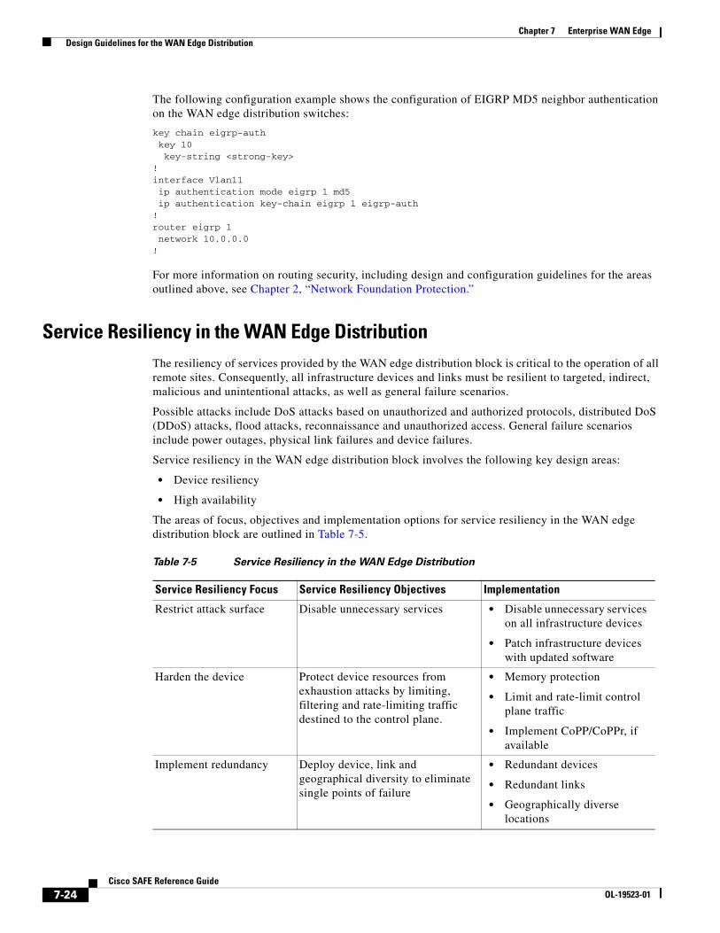
Service Resiliency in the WAN Edge DistributionThe resiliency of services provided by the WAN edge distribution block is critical to the operation of all remote sites. Consequently, all infrastructure devices and links must be resilient to targeted, indirect, malicious and unintentional attacks, as well as general failure scenarios.
Possible attacks include DoS attacks based on unauthorized and authorized protocols, distributed DoS (DDoS) attacks, flood attacks, reconnaissance and unauthorized access. General failure scenarios include power outages, physical link failures and device failures.
Service resiliency in the WAN edge distribution block involves the following key design areas:
• Device resiliency
• High availability
The areas of focus, objectives and implementation options for service resiliency in the WAN edge distribution block are outlined in Table 7-5.
Table 7-5 Service Resiliency in the WAN Edge Distribution
Service Resiliency Focus Service Resiliency Objectives Implementation
Restrict attack surface Disable unnecessary services • Disable unnecessary services on all infrastructure devices
• Patch infrastructure devices with updated software
Harden the device Protect device resources from exhaustion attacks by limiting, filtering and rate-limiting traffic destined to the control plane.
• Memory protection
• Limit and rate-limit control plane traffic
• Implement CoPP/CoPPr, if available
Implement redundancy Deploy device, link and geographical diversity to eliminate single points of failure
• Redundant devices
• Redundant links
• Geographically diverse locations
7-24Cisco SAFE Reference Guide
OL-19523-01

Chapter 7 Enterprise WAN Edge Design Guidelines for the WAN Edge Distribution
For more information on service resiliency, including design and configuration guidelines for the areas highlighted in Table 7-5 above, see Chapter 2, “Network Foundation Protection.”
Service resiliency should be complemented by network policy enforcement techniques that filter traffic at the network edges, permitting only authorized services and originators to directly address the infrastructure. These techniques restrict accessibility to the infrastructure in order to reduce exposure to unauthorized access, DoS, and other network attacks. For more information, refer to the “Network Policy Enforcement in the WAN Edge Aggregation” section on page 7-13.
Switching Security in the WAN Edge DistributionSwitching in the WAN edge distribution block is critical to service availability and, as such, it must be properly secured to protect it against compromise, including unauthorized access and DoS attacks through Spanning Tree Protocol (STP) manipulation and Layer-2 flooding.
The threat exposure of a switch in the WAN edge distribution block is, however, limited as all interfaces are to infrastructure devices and there are no external interfaces. However, it is recommended that all the key areas of focus be reviewed and applied, as outlined in the “Switching Infrastructure Best Practices” section on page 2-25.
Secure Device Access in the WAN Edge DistributionAccess to all infrastructure devices in the WAN edge distribution block must be secured. If infrastructure device access is compromised, the security and management of the entire network can be compromised. Consequently, it is critical to establish the appropriate controls in order to prevent unauthorized access to infrastructure devices.
There will be some variations in the actual implementation of secure device access, based on the particular device and software release, but all the fundamental objectives must be applied:
• Restrict device accessibility
Limit the accessible ports and access services, restrict access to authorized services from authorized originators only, enforce session management, and restrict login vulnerability to dictionary and DoS attacks.
• Present legal notification
Display legal notice, developed in conjunction with company legal counsel, for interactive sessions.
• Authenticate access
Ensure access is only granted to authenticated users, groups, and services.
• Authorize actions
Restrict the actions and views permitted by any particular user, group, or service.
• Ensure the confidentiality of data
Protect locally stored sensitive data from viewing and copying. Consider the vulnerability of data in transit over a communication channel to sniffing, session hijacking and man-in-the-middle (MITM) attacks.
• Log and account for all access
Record who accessed the device, what occurred, and when for auditing purposes.
For more information on secure device access, including design and configuration guidelines for the areas outlined above, see Chapter 2, “Network Foundation Protection.”
7-25Cisco SAFE Reference Guide
OL-19523-01

Chapter 7 Enterprise WAN Edge Design Guidelines for the WAN Edge Distribution
In addition, the isolation of management access and management traffic is recommended in order to provide an extra degree of security. This is typically employed using an out-of-band (OOB) network that is physically independent of the data network and features limited and strictly controlled access. For more information on implementing a management network, see Chapter 9, “Management.”
Telemetry in the WAN Edge DistributionThe WAN edge serves as a key hub for remote sites and is vital to the service availability of a branch. Visibility into its status and any anomalous activity taking place is thus critical to the timely and accurate cross-network detection and mitigation of anomalies.
Telemetry is thus a fundamental element, enabled across all devices in the WAN edge and integrated with dedicated analysis systems to collect, trend and correlate observed activity. The key elements include the following:
• Synchronize time
Synchronize all network devices to the same network clock by using Network Time Protocol (NTP) to enable accurate and effective event correlation.
• Monitor system status information
Maintain visibility into overall device health by monitoring CPU, memory and processes.
• Implement CDP best common practices
Enable CDP on all interfaces in order to facilitate operations. The WAN edge distribution block does not feature any access or external-facing interfaces, so CDP does not pose a risk in this location.
• Enable remote monitoring
Leverage syslog, SNMP to a centralized server, such as CS-MARS, for cross-network data aggregation. This enables detailed and behavioral analysis of the data which is key to traffic profiling, anomaly-detection and attack forensics, as well as general network visibility and routine troubleshooting.
For more information on telemetry, including design and configuration guidelines for the areas outlined above, see Chapter 2, “Network Foundation Protection.”
For more information on remote monitoring, analysis and correlation, including syslog, SNMP, and NetFlow, see Chapter 10, “Monitoring, Analysis, and Correlation.”
Design Considerations
• As with secure device access, the isolation of management access and management traffic is recommended using an out-of-band (OOB) network in order to provide an extra degree of security. This is typically employed using an OOB network that is physically independent of the data network and features limited and strictly controlled access. For more information on the implementation of a management network, refer to Chapter 9, “Management.”
7-26Cisco SAFE Reference Guide
OL-19523-01

Chapter 7 Enterprise WAN Edge Threats Mitigated in the Enterprise WAN Edge
Threats Mitigated in the Enterprise WAN EdgeTable 7-6 Enterprise WAN Edge Threat Mitigation Features
Botnets DoSUnauthorized Access
Malware,Spyware
Application,Network Abuse
Data Leakage Visibility Control
Secure WAN Connectivity Yes Yes Yes
Routing Security Yes Yes Yes Yes
Service Resiliency
Device Hardening
QoS
Redundancy
Yes Yes Yes
Network Policy Enforcement
WAN Edge ACLs
Cisco Firewall
uRPF
Yes Yes Yes Yes Yes
Cisco IPS Integration Yes Yes Yes Yes
Switching Security Yes Yes Yes Yes
Secure Device Access Yes Yes Yes Yes
Telemetry Yes Yes Yes Yes Yes Yes
7-27Cisco SAFE Reference Guide
OL-19523-01

Chapter 7 Enterprise WAN Edge Threats Mitigated in the Enterprise WAN Edge
7-28Cisco SAFE Reference Guide
OL-19523-01