Embed Size (px)
Citation preview

Department of Public Works Fall Creek Evaluation Study
U.S. Army Corps of Engineers Final Report
7. CONSTRUCTION CONSIDERATIONS
7-1
This section of the report describes constructability considerations for large and small
diameter rock tunnels, soft ground tunnels, and drop shafts in soil and rock. This
includes excavation methods, support systems, and lining alternatives for the Fall
Creek/White River Tunnel project.
7.1 SAFETY
Underground construction is subject to more safety related risks than most types of
construction projects. These risks need to be managed during the design and
construction of the project. During design, the safety related risks unique to the
project should be defined and minimized, as described in Section 9 – Risk
Management. The contract documents should require the tunneling contractor to be
solely and completely responsible for safety conditions at the jobsite, including safety
of all persons (including employees) and property during construction. Project safety
provisions should conform to U.S. Department of Labor Occupational Safety and
Health Administration (OSHA) requirements, specifically including, but not limited to,
the Federal Occupational Safety and Health Act of 1970, as amended, and the
Indiana Occupational Safety and Health Act. The Contractor should comply with the
common law standards of due care and develop a Construction Safety Program that
addresses all safety related concerns, which may require the need for a project
safety officer. The Contractor should also comply with the U.S. Army Corps of
Engineers safety requirements in Engineers Manual EM 385-1-1, if the project is
managed by the Corps.
7.2 MAIN TUNNEL CONSTRUCTION
Depending on the required percent (95 or 97) capture and the selected alignment,
the main tunnel’s finished diameter and length will range from 26 to 35 feet and 7.5 to
10.5 miles, respectively. It is anticipated that the tunnel will be located in limestone
and dolomitic rock at depths greater than 200 feet below ground surface (bgs).

Department of Public Works Fall Creek Evaluation Study
U.S. Army Corps of Engineers Final Report
7. CONSTRUCTION CONSIDERATIONS
7-2
7.2.1 Excavation, Support and Lining
The Fall Creek/White River Tunnel can be excavated by drill-and-blast mining or
mechanical excavation, such as a conventional tunnel boring machine (TBM) or an
earth pressure balance machine (EPBM). The most economical mining method will
be mechanical excavation using a TBM. Some advantages of mechanical
excavation over drill-and-blast mining include:
♦ Potentially high average advance rates in favorable rock conditions from a
single heading
♦ Excavation of a circular tunnel cross-section with minimal over-breaking of the
rock that will require less concrete for lining
♦ Minimal impact on adjacent structures in terms of settlement of soils or blast
vibrations
♦ Reduced initial rock support requirements
♦ Less labor intensive
♦ Provides a safer working environment
♦ Allows 24-hour work days in urban areas with minimal noise restrictions
Mechanical excavation, in particular a conventional TBM, can be used to mine
through the carbonate rock anticipated for the Fall Creek/White River Tunnel
project. A TBM mines the rock using a rotating circular cutterhead. The
cutterhead rotates at a low revolution per minute. The rolling disc cutters on the
face of the TBM cut the rock into chips, which are removed by a conveyor belt.
Grippers push out against the rock and advance the TBM forward during mining.
After a few feet of mining, the body of the TBM is pulled up to the cutterhead and
re-gripped to the previously excavated wall and mining is resumed. Initial
support is erected in the tail shield of the TBM. It is anticipated that the crown of
the tunnel will require pattern rock bolts for initial support. In areas needing
additional support, rock bolts should be supplemented with wire mesh, steel

Department of Public Works Fall Creek Evaluation Study
U.S. Army Corps of Engineers Final Report
7. CONSTRUCTION CONSIDERATIONS
7-3
straps, channels, and circumferential steel sets with lagging. It is anticipated that
the tunnel will be lined with unreinforced concrete along most of the alignment.
The concrete should be reinforced with steel, as required, to support zones of
weaker rock and shaft connections. Typically, the cast-in-place concrete lining is
installed following the mining of the entire tunnel. However, if hydrogeologic
conditions indicate that groundwater inflows may significantly impact adjacent
water wells, the concrete may be placed behind the TBM trailing gear while the
tunnel is being mined. This installation method would significantly slow the
advance rate of the tunnel, but would reduce the tunnel’s impact on the existing
water well fields.
Conventional TBM Equipped for Pre-Excavation Grouting
Department of Public Works Fall Creek Evaluation Study
U.S. Army Corps of Engineers Final Report
7. CONSTRUCTION CONSIDERATIONS
7-4
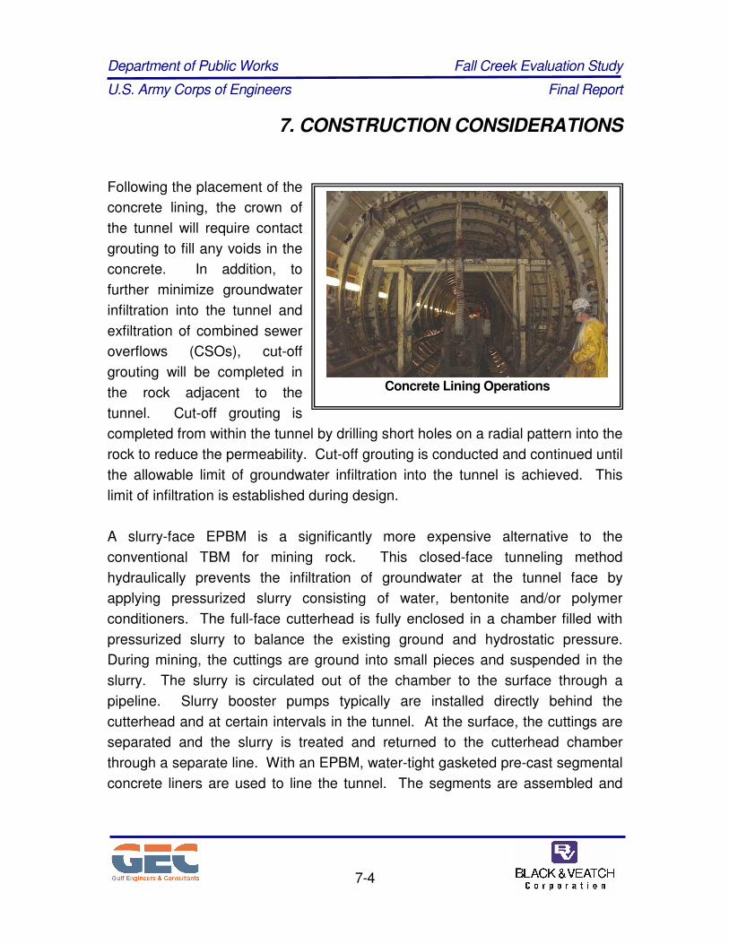
Following the placement of the
concrete lining, the crown of
the tunnel will require contact
grouting to fill any voids in the
concrete. In addition, to
further minimize groundwater
infiltration into the tunnel and
exfiltration of combined sewer
overflows (CSOs), cut-off
grouting will be completed in
the rock adjacent to the
tunnel. Cut-off grouting is
completed from within the tunnel by drilling short holes on a radial pattern into the
rock to reduce the permeability. Cut-off grouting is conducted and continued until
the allowable limit of groundwater infiltration into the tunnel is achieved. This
limit of infiltration is established during design.
A slurry-face EPBM is a significantly more expensive alternative to the
conventional TBM for mining rock. This closed-face tunneling method
hydraulically prevents the infiltration of groundwater at the tunnel face by
applying pressurized slurry consisting of water, bentonite and/or polymer
conditioners. The full-face cutterhead is fully enclosed in a chamber filled with
pressurized slurry to balance the existing ground and hydrostatic pressure.
During mining, the cuttings are ground into small pieces and suspended in the
slurry. The slurry is circulated out of the chamber to the surface through a
pipeline. Slurry booster pumps typically are installed directly behind the
cutterhead and at certain intervals in the tunnel. At the surface, the cuttings are
separated and the slurry is treated and returned to the cutterhead chamber
through a separate line. With an EPBM, water-tight gasketed pre-cast segmental
concrete liners are used to line the tunnel. The segments are assembled and
Concrete Lining Operations

Department of Public Works Fall Creek Evaluation Study
U.S. Army Corps of Engineers Final Report
7. CONSTRUCTION CONSIDERATIONS
7-5
installed in the tail shield, and the annular space between the segments and rock
is grouted.
Ground conditions will determine the most effective technique and equipment for
mechanical excavation (conventional TBM or slurry-face EPBM). This determination
can not be made until an exploration program has been conducted to obtain the
geotechnical and hydrogeologic properties of the rock formations along the tunnel
alignment. It is anticipated that dewatering along the main tunnel alignment will not
be feasible because the tunnel is located 200 to 250 feet below the groundwater
surface in a productive aquifer. Therefore, a groundwater control method other than
dewatering will be required during excavation and lining. Groundwater control
options include modifying the ground before excavation by pre-excavation grouting or
tunneling with a water tight system such as slurry-face EPBM with gasketed concrete
liner segments. Although the geologic and hydrogeologic properties of the rock
require further definition, it is anticipated that pre-excavation grouting will be the most
successful and cost effective technique to control groundwater. Pre-excavation
grouting from the tunnel face helps to control and prevent high water inflows into the
tunnel when mining.
Pre-excavation grouting entails advancing probe holes up to a couple hundred
feet in front of the tunnel face and measuring the groundwater flow rate. If the
groundwater flow rate into the probe holes exceeds a certain threshold value,
primary grout holes are drilled and pressure-grouted along with the probe holes.
Verification probe holes are then advanced to determine if additional grouting
before advancing the TBM is necessary based on the inflow threshold value
established for the project. Inflow threshold values would be determined upon
conclusion of the geotechnical exploration program during the detailed design
phase of the project. Once the rock is grouted sufficiently and allowed to setup
for a minimum time period, the mining activities are resumed. Grouting
consultants may be required depending on the rock and groundwater conditions
discovered during further geotechnical investigations, and during construction.

Department of Public Works Fall Creek Evaluation Study
U.S. Army Corps of Engineers Final Report
7. CONSTRUCTION CONSIDERATIONS
7-6
Tunneling in rock using a slurry-face EPBM typically is more costly than using a
TBM. EPBM advance rates are significantly less, which adds cost. The gasketed
pre-cast segmental liners also can be at least twice as expensive as a cast-in-place
concrete liner. In addition, successful mining of large diameter tunnels (30-foot
diameter or greater) in rock under high hydrostatic pressures with a slurry-face
EPBM has not been done in the United States. Therefore, until additional
geotechnical and hydrogeologic information is available, it is anticipated that
conventional mining using a TBM and a properly designed pre-excavation grouting
program will be the more cost effective construction method.
7.3 CONNECTION TUNNEL CONSTRUCTION
Tunnels conveying CSOs from the drop shafts to the main tunnel will be
constructed in rock and possibly soil depending on the selected main tunnel
alignment. Approximately 20 connection tunnels will be required for this project.
7.3.1 Excavation, Support and Lining of Rock Connection Tunnels (Adits)
It is anticipated that relatively short connection tunnel lengths will be constructed
in rock by drill-and-blast mining. Depending on the geotechnical and
hydrogeologic properties, pre-excavation grouting of the rock from the tunnel
face may be required prior to blasting to control groundwater inflow. Probing in
front of the blast face and measuring the inflow rate will be performed to
determine the need for pre-excavation grouting. If the measured flow rates
exceed established design criteria, pre-excavation grouting will be performed in
advance of the blasting face. Dewatering is not expected to be a viable option to
control groundwater while constructing connection tunnels in rock.
Following pre-excavation grouting, the rock will be prepared for blasting by
drilling holes in a pattern and loading the explosives. After blasting, supports will
be installed in the fresh excavation. These supports may include rock bolts, wire
Department of Public Works Fall Creek Evaluation Study
U.S. Army Corps of Engineers Final Report
7. CONSTRUCTION CONSIDERATIONS
7-7
mesh, shotcrete, and/or steel sets. It is anticipated that the blasted rock will be
removed in conjunction with the associated drop shaft excavation so that the
connection tunnel construction is not on the construction schedule’s critical path.
Depending on the diameter, rock connection tunnels can be lined with cast-in-
place concrete or pipe. Available materials include pre-stressed concrete
cylinder pipe (PCCP), Hobas pressure pipe, high density polyethylene (HDPE)
pipe, ductile iron pipe (DIP), mortar-lined steel pipe, polymer concrete pipe, and
reinforced concrete pipe (RCP). Material selection will be based upon connection
tunnel characteristics, ground conditions, and diameter and will be further
evaluated during the detailed design phase of the project. If pipe is used as the
liner, the annular space between the pipe and the initial support and rock will be
filled with cellular concrete, concrete, or grout.
7.3.2 Excavation, Support, and Lining of Soft Ground Connection Tunnels
Soft ground tunnels will be located in a productive aquifer that provides water for
municipal use. It is expected that the aquifer contains saturated alluvial materials
consisting primarily of sand. Groundwater control will be required during
tunneling. For the soft ground tunnels, the groundwater inflow can be controlled
through conventional TBM methods while dewatering using compressed air or
tunneling with a mechanical EPBM and a water-tight liner.
For soft ground tunnel construction, dewatering along the entire alignment is not
anticipated to be practical. However, limited dewatering applications may be
beneficial for shorter localized connection lengths. This limited dewatering is
anticipated only when connecting short soft ground tunnels to longer (primary)
soft ground tunnels. Soft ground tunnels could be excavated by pipe-jacking,
microtunneling, or using an open-face tunneling methodology within a shield and
an excavating bucket or spade.

Department of Public Works Fall Creek Evaluation Study
U.S. Army Corps of Engineers Final Report
7. CONSTRUCTION CONSIDERATIONS
7-8
As the tunnel advances,
dewatering should continue
until a water-tight initial
support or final lining is
installed. For a single-pass
system, water-tight initial
support options include jacked
pipe, gasketed steel liner
plates and gasketed pre-cast
segmental concrete. For a
two-pass system, the
recommended support system
includes circumferential steel
ribs with wood lagging
spanning between the ribs or steel liner plates.
Depending on the diameter, the soft ground connection tunnels can be lined with
cast-in-place concrete or pipe. Available materials include pre-stressed concrete
cylinder pipe (PCCP), Hobas pressure pipe, high density polyethylene (HDPE)
pipe, ductile iron pipe (DIP), mortar-lined steel pipe, polymer concrete pipe, and
reinforced concrete pipe (RCP). If pipe is used as the liner, the annular space
between the pipe and the initial support will be filled with cellular concrete,
concrete, or grout.
Compressed air may be used for the construction of soft ground tunnels beneath
the water table. The compressed air method involves constructing the entire
tunnel under elevated air pressures to overcome the hydrostatic pressure in the
ground. The elevated air pressure prevents groundwater from flowing into the
tunnel and prevents ground instability. This elevated air pressure maintains
acceptable working conditions in the open excavation. This method is seldom
used because of the relatively high cost associated with restricted working hours
Steel Ribs and Wood Lagging Installation

Department of Public Works Fall Creek Evaluation Study
U.S. Army Corps of Engineers Final Report
7. CONSTRUCTION CONSIDERATIONS
7-9
under elevated pressure; lost time for decompressing the workers; and safety-
related concerns associated with working under elevated pressures. The
compressed air method also includes an elevated fire hazard. The hazard is due
to the oxygen-rich environment and blowouts of air into openings in the
subsurface that cause the excavation to become unstable or groundwater to flow
into the tunnel. It is anticipated that compressed air tunneling will not be
considered for this project since mechanical tunneling can be done at a
competitive cost and provides a safer working environment.
A mechanical EPBM will be used to drive and construct all soft ground
connection tunnels that are below the water table; in areas where dewatering is
not feasible; and are of considerable length. A screw conveyor removes the
excavated material from the
EPBM’s pressurized chamber
and the muck is conveyed to
the surface. It is anticipated
that the excavated sand will
require conditioning with slurry
or polymers in the working
chamber to reduce friction and
torque in the cutterhead and
screw conveyor. Pre-cast
concrete segmental liners will
be erected in the EPBM’s tail
shield as it advances. These
liners serve as the support
and final lining of the tunnel.
Soft Ground EPBM

Department of Public Works Fall Creek Evaluation Study
U.S. Army Corps of Engineers Final Report
7. CONSTRUCTION CONSIDERATIONS
7-10
7.4 SHAFT CONSTRUCTION
Working, retrieval, intermediate working, Deep Tunnel Pump Station, access,
and drop shafts will be constructed for this project. The working, retrieval,
intermediate working, Deep Tunnel Pump Station, and any soft ground tunnel
working and retrieval shafts will be large in diameter. The access and drop
shafts are anticipated to be 14 feet or less in diameter. Shafts associated with
the main tunnel, Deep Tunnel Pump Station, drop shafts, and shafts conveying
CSOs from soft ground tunnels to the main tunnel will extend into rock. Shafts
associated solely with shallow soft ground tunneling will not extend into rock.
7.4.1 Excavation, Support and Lining
The shaft construction methods for this project will depend on the geotechnical
and hydrogeologic properties of the soil and rock at each shaft location. It is
assumed that the soils consist primarily of saturated sand and are 65 to 120 feet
deep along the alignment. Based on available geotechnical information, the
sand is underlain by jointed limestone and dolomite units, which constitute a
productive bedrock aquifer. Dewatering during shaft construction is considered
impractical because of the requirement to draw down the piezometric surface
200 to 300 feet below ground surface. Dewatering may be feasible during soft
ground tunneling for shallow shafts if the impact to adjacent water supply wells
can be controlled.
During and after excavation, shafts will require support in the soil and at the soil/rock
interface. The type of shaft support used will depend on the excavation method; the
behavior and stability of the soil; and groundwater control method. Groundwater
control should continue until a water-tight support or lining is installed.

Department of Public Works Fall Creek Evaluation Study
U.S. Army Corps of Engineers Final Report
7. CONSTRUCTION CONSIDERATIONS
7-11
7.4.2 Main Tunnel Working, Retrieval, Intermediate Working, and Deep
Tunnel Pump Station Shafts
The main tunnel’s working, retrieval, intermediate working, and deep tunnel
pump station shafts are anticipated to be 40 to 50 feet in diameter and at a depth
of 100 to 200 feet into rock. Groundwater control will be required until a water-
tight liner is installed. Construction methods used for large diameter shafts in
productive aquifers include:
♦ Constructing a slurry wall through the overburden and pre-excavation grouting
prior to blasting the rock
♦ Freezing the groundwater in the soil and rock
♦ Sinking caissons through soil and blasting rock following pre-excavation
grouting
♦ Constructing secant piles through soil and blasting rock following pre-
excavation grouting.
The typical slurry wall construction sequence includes:
♦ Drill and grout the
bedrock from the ground
surface using tightly
spaced grout holes
located in two circular
rows around the planned
shaft’s perimeter
♦ Excavate trenches to the
bedrock and hold open
using a slurry around the
shaft perimeter
Clamshell for Slurry Wall Construction

Department of Public Works Fall Creek Evaluation Study
U.S. Army Corps of Engineers Final Report
7. CONSTRUCTION CONSIDERATIONS
7-12
♦ Key slurry trenches into
the bedrock using a
clam shell, chisel, or
hydro-fraise depending
on the geology
♦ Lower a rebar cage into
the slurry trench to
displace concrete
♦ Excavate the interior
concrete walls to the
rock
♦ Blast and remove rock
from the hole in intervals
until the final depth is reached
♦ Support rock
♦ Install reinforced concrete liner/structure the entire depth of the shaft
The working, retrieval, intermediate working, and Deep Tunnel Pump Station
shafts should be lined with reinforced concrete. The working shaft will be
converted into the screening shaft and connected to the Deep Tunnel Pump
Station shaft by a connection tunnel.
7.4.3 Soft Ground Tunnel Working and Retrieval Shafts
Soft ground tunneling shafts will be approximately 15 to 25 feet in diameter and
are anticipated to be constructed only in soil. Commonly, these shafts are
braced excavations. Trackhoes and clamshells remove the soil while the
formation is dewatered. However, since the main working and retrieval shafts
associated with the soft ground tunnels are located adjacent to Fall Creek, White
River, or the City’s well fields, dewatering may not be advisable or feasible.
Slurry Wall Constructed Shaft

Department of Public Works Fall Creek Evaluation Study
U.S. Army Corps of Engineers Final Report
7. CONSTRUCTION CONSIDERATIONS
7-13
A caisson is a cost effective
alternative to construct these
shafts. The caisson is designed
as the final reinforced concrete
lining of the shaft to carry all
earth and hydrostatic loads.
The typical sequence for sinking
a caisson includes:
♦ Excavate shallow trench
around the perimeter of
the shaft to identify
shallow obstructions
♦ Pour short circular
reinforced concrete lift (shaft wall) in forms set in the trench with the bottom of
the wall fitted with a steel cutting shoe
♦ Excavate soil in the shaft interior and pour an additional reinforced concrete lift
varying from about 8 to 20
feet high on top of the
existing wall
♦ Excavate soil in the shaft
interior as the shaft wall
slides down by gravity
♦ Add weights to assist the
sliding process
♦ Place bentonite along the
outside of the shaft walls
to provide lubrication
♦ Continue the previous
steps until the final depth
of the shaft is reached
Caisson Construction
Braced Shaft Excavation

Department of Public Works Fall Creek Evaluation Study
U.S. Army Corps of Engineers Final Report
7. CONSTRUCTION CONSIDERATIONS
7-14
♦ Allow water to remain
inside the wall to equalize
the groundwater pressure
and prevent the sand from
heaving up into the
caisson during excavation
♦ Construct thick concrete
bottom plug under water
at the base of the
excavation that is
structurally tied to the
shaft walls to prevent the
caisson from floating
♦ Remove water from the
caisson interior once the bottom concrete plug has cured
Drilled secant piles or driven sheet piles with
a bottom plug are other alternative
construction methods. These methods
require that a reinforced concrete liner shaft
be placed inside the secant pile or sheet pile
perimeter to complete the shaft construction.
7.4.4 Drop Shafts and Access Shafts
It is anticipated that all of the drop and access
shafts will be drilled through soil with rock
excavated by blasting. Large pier drilling rigs
may be utilized to drill holes in the soil up to
14 feet in diameter. It is anticipated that
these drops will serve as the working shafts
Drilled Shaft Equipment
Shaft Excavation while Sinking a Caisson

Department of Public Works Fall Creek Evaluation Study
U.S. Army Corps of Engineers Final Report
7. CONSTRUCTION CONSIDERATIONS
7-15
for the small connection tunnels. Therefore, the shaft diameter should be larger
than the estimated 2 to 7 feet needed for the drop pipe alone to accommodate
these activities. Working from each drop shaft to construct the connection
tunnels should allow for minimal interferences between multiple contractors and
ensure not being on the schedule’s critical path.
Prior to drilling the shaft, tightly spaced pre-
excavation grout holes should be drilled
and grouted in two circles around the
perimeter of the shaft. The shaft should be
drilled blind through the overburden using a
slurry to keep the borehole open and return
the cuttings to the surface. The borehole
should be drilled into rock a short distance
and cased with steel. Due to the large
diameter, the steel casing needs to be
welded together at the shaft site and
lowered into the hole in sections. Once the
section is lowered in the hole, it should be
suspended with cables and/or chains while
the next section is lifted and welded to it.
This process is repeated until the bottom of
the hole is reached. The annular space between the ground and casing should
be grouted. Once the grout sets, the casing interior should be dewatered so that
rock mining can commence. The rock should be drilled and blasted in vertical
intervals until the final shaft depth is reached. When excavating in rock, the shaft
may require little or no support. If necessary, the rock can be supported with
rock bolts and/or shotcrete with or without steel reinforcing. Highly fractured or
broken rock zones in the shaft can be lined with steel ribs and lagging or steel
liner plates, which can be made water-tight by gaskets.
Steel Casing for Drilled Shaft

Department of Public Works Fall Creek Evaluation Study
U.S. Army Corps of Engineers Final Report
7. CONSTRUCTION CONSIDERATIONS
7-16
Raise bore is a construction method that entails drilling from the connection tunnel up
to the ground surface. This construction method will not be feasible because the
shaft needs to be constructed prior to the connection tunnel to ensure not being on
the schedule’s critical path.
The lining of each drop shaft will vary depending on the shaft configuration. If a
plunge drop configuration is used, the shaft and deaeration chamber should be lined
with reinforced concrete. If a vortex drop configuration is used, each shaft should
have a CSO drop pipe with an estimated inside diameter of 2 to 7 feet. The drop
pipe could be constructed using Hobas pressure pipe or HDPE. However, the
maximum diameter for HDPE is 63 inches. The drop pipe is encased in concrete
along the entire length to prevent buckling. Any remaining annular space is filled with
flowable or granular fill.
The advantages and disadvantages of the construction methods are presented in
Table 7.1. The preferred method for shaft construction is a slurry wall through
the overburden and pre-excavation grouting prior to blasting rock.

Department of Public Works Fall Creek Evaluation Study
U.S. Army Corps of Engineers Final Report
7. CONSTRUCTION CONSIDERATIONS
7-17
Table 7.1
Construction Methods
Construction Method Advantages Disadvantages
Constructing a slurry wall through
the overburden and pre-excavation
grouting prior to blasting the rock
♦ Effective
groundwater control
if properly
constructed and
keyed into bedrock
♦ If not keyed into
bedrock, groundwater
inflow will occur at the
soil/rock interface
♦ Larger area needed
for shaft construction
Freezing the groundwater in the soil
and rock
♦ Smaller area
needed for shaft
construction
compared to slurry
wall construction
♦ Provides reliable
groundwater control
at the soil/ rock
interface if the
hydrogeologic
conditions are
favorable
♦ Expensive
♦ Can only be applied
in appropriate
hydrogeologic
environments
Sinking caissons through soil and
blasting rock following pre-
excavation grouting
♦ Smaller area
needed for shaft
construction
compared to slurry
wall construction
♦ Could be keyed into
shale bedrock to
limit groundwater
inflows
♦ May be more cost
effective than slurry
wall construction
♦ Caissons are difficult
to key into limestone
or dolomitic rock
♦ Leaves a pathway for
groundwater and soil
infiltration into the
excavation

Department of Public Works Fall Creek Evaluation Study
U.S. Army Corps of Engineers Final Report
7. CONSTRUCTION CONSIDERATIONS
7-18
Table 7.1
Construction Methods
Construction Method Advantages Disadvantages
Constructing secant piles through
soil and blasting rock following pre-
excavation grouting
♦ Smaller area
needed for shaft
construction
compared to slurry
wall construction
♦ Potentially more
cost effective than
slurry wall
construction
♦ Secant piles are
difficult to drill to
these depths without
creating windows for
groundwater and soil
inflows due to
deviation of the holes
during drilling
7.5 POWER AVAILABILITY
The TBM and associated trailing gear for the main tunnel will require a significant
amount of power for operation. The size of the tunnel and geotechnical properties of
the rock will dictate the power requirements. All of the working shaft site alternatives
should be located in or near industrial areas. Therefore, it is anticipated that power
will be available at the site for TBM operation. Drill-and-blast mining and soft ground
tunneling machines require less power. Further investigation during design should
be performed to evaluate power requirements for the TBM and EPBM.
Sufficient power is likely available for the Deep Tunnel Pump Station and screen
facility if the preferred Bluff Road working shaft site is selected. Subsequent design
phases should examine the power requirements.

Department of Public Works Fall Creek Evaluation Study
U.S. Army Corps of Engineers Final Report
7. CONSTRUCTION CONSIDERATIONS
7-19
7.6 HANDLING AND DISPOSAL OF TUNNEL AND SHAFT SPOILS
Spoils (muck) from the main tunnel will be transported from the TBM trailing gear to
the working shaft by muck trains pulled by locomotives or conveyor belts. An area
should be available onsite to temporarily stockpile the muck. It is anticipated that
trucks will be transporting muck from the working shaft site to the disposal site(s)
each day the TBM is advancing. Approximately 2,500 cubic yards of material will be
generated daily, assuming the tunnel has a 34-foot excavated diameter; advances at
an average rate of 50 feet per day; and using a bulking factor of 1.5. This volume will
result in approximately 125 trucks per day, with a volume of 20-cubic yards,
transporting muck from the working shaft to the disposal site. For traffic impact and
cost considerations, adjacent disposal sites should be identified during design. In
addition, following the geotechnical investigation, local quarry operators should be
contacted to determine their interest in the material. Rock tunnel muck is expected to
be suitable for many applications, particularly related to roadway construction.
Special consideration may be necessary to handle and dispose of the spoil
generated from the EPBM tunneling. This material, consisting of soil, water,
bentonite, and/or polymers and conditioners, may require an offsite location for
disposal.
7.7 HANDLING, TREATMENT AND DISCHARGE OF TUNNEL WATER
The contract documents should include provisions for the contractor to handle, treat,
and discharge the water generated during shaft and tunnel construction. The
provisions should include a package treatment plant at the working shaft site to
remove total suspended solids and contaminants prior to discharge. Following
treatment, it is anticipated that the water will be discharged to White River. Also, a
small package treatment plant may be necessary at the retrieval shaft or drop shafts
along the alignment to remove suspended solids and contaminants prior to discharge
into White River or Fall Creek. Further characterization of the subsurface is

Department of Public Works Fall Creek Evaluation Study
U.S. Army Corps of Engineers Final Report
7. CONSTRUCTION CONSIDERATIONS
7-20
necessary to estimate the volume and quality of water to be treated during
construction. A permit will be required to discharge the treated water to White River
or Fall Creek.
7.8 PROTECTION OF EXISTING STRUCTURES
Protecting existing structures from damage will be addressed during design and
construction. A pre-condition survey should be required of the contractor prior to
executing shaft or tunnel construction. Instrumentation will be required to monitor
settlement, ground movement, and impacts to groundwater. Inclinometers and
vibration monitoring instruments (seismographs) will be located on structures; on
utilities; at the ground surface; and at observation wells. Periodic readings before,
during, and after construction will allow for a quick response if the monitoring limits
are exceeded. These responses can include:
♦ Ceasing the operation and developing a corrective action plan
♦ Providing additional protection measures to the structures
♦ Requiring a change in the contractor’s methodology
The effects on existing structures during construction may be minimized since the
tunnel will be mined in deep rock. Settlement is not anticipated to be an issue,
excluding an encounter with a major filled joint connected to the overburden flowing
into the tunnel face. Minimal vibrations may be noticed at the surface within a couple
hundred feet of the operating TBM. However, the vibrations will occur over a short
duration and are not anticipated to be of a magnitude that causes structural damage.
To the extent possible, the main tunnel alignments were routed away from vibration
sensitive structures, such as hospitals.
Tunneling in soil typically increases the risk of damaging nearby structures or
property. While some of these risks associated with ground loss and settlement can
be mitigated using a mechanical EPBM, the potential to damage existing structures is
Department of Public Works Fall Creek Evaluation Study
U.S. Army Corps of Engineers Final Report
7. CONSTRUCTION CONSIDERATIONS
7-21
present. This includes causing surface settlement and encountering an unknown
utility and disrupting service. Surface settlement caused by ground loss at the tunnel
heading can occur when the tunnel envelope is over-excavated. This happens when
an obstruction straddling the tunnel envelope is removed in its entirety at the cutting
face and creates a void behind the tunnel shield. Sand has a tendency to collapse in
this void prior to the lining installation. Settlement can occur if the void caused by the
collapsing sand travels up to the surface. In addition, if not controlled, the circulation
fluid that pressurizes the face can be lost to an opening in the subsurface. This will
cause the observed pressure at the tunnel face to be higher than at the cutterhead
chamber. Water and soil may flow into the tunnel and potentially result in surface
settlement. While these risks exist, they can be mitigated with proper design using
data obtained from a geotechnical program and sound construction practices.
Ground loss also can occur during shaft construction causing settlement and
potentially damaging nearby structures. Proper design and construction practices
along with a sufficient monitoring program can assist to mitigate these risks.


![Exacerbation of blast-induced ocular trauma by an …...Ocular blast injury Blast wave exposure was performed as previously de-scribed [8]. Briefly, anesthetized mice were secured](https://img.dokumen.tips/doc/110x75/5fbfd472f884632b560bc652/exacerbation-of-blast-induced-ocular-trauma-by-an-ocular-blast-injury-blast.jpg)