Embed Size (px)
DESCRIPTION
MANUAL MANUAL LG
Citation preview

6RMG0-01C
General Wall Mounted(60Hz/R410A)

2 General Wall Mounted
General Wall Mounted
Publication history
Test condition of international standard
General Description
1. Models line up .....................................................................................6
2. Nomenclature ......................................................................................7
3. Specifications .....................................................................................8
4. Dimensional Drawings .....................................................................10
5. Wiring diagrams ................................................................................15
6. Refrigerant cycle diagram ................................................................18
7. Capacity tables..................................................................................19
8. Capacity coefficient factor ...............................................................21
9. Operation range ................................................................................23
10. Air velocity and temperature distribution(reference data)..........24
11. Controller ........................................................................................26
12. Installation .......................................................................................27
13. Installation Guide at the Seaside...................................................42

3
Publication history6RMG0-01C
General Wall Mounted
Publication historyPlb.No Outdoor Units Notes Publication in
6RMG0-01A All models Added N.A models May. 2010
6RMG0-01B All models Change operation range Sep. 2010
6RMG0-01C All models Change motor spec Oct. 2010

4
Test condition of international standard 6RMG0-01C
General Wall Mounted
Test condition of international standardCLASSIFICATION KSC ISO ARI AHAM AS SSA
9306 5151 210/240 1861.1 385
IndoorDB°C(°F) 27.0 27.0 26.7(80) 26.7(80) 27.0 29.0
Cooling WB°C(°F) 19.5 19.0 19.4(67) 19.4(67) 19.0 19.0
CapacityOutdoor
DB°C(°F) 35.0 35.0 35.0(95) 35.0(95) 35.0 46.0
WB°C(°F) 24.0 24.0 23.9(75) 23.9(75) 24.0 24.0
IndoorDB°C(°F) 20.0 20.0 21.1(70) 21.1(70) 21.0 21.0
Heating WB°C(°F) 15.0 15.0 15.6(60) 15.6(60) 15.0 15.5
CapacityOutdoor
DB°C(°F) 7.0 7.0 8.3(47) 8.3(47) 7.0 7.0
WB°C(°F) 6.0 6.0 6.1(43) 6.1(43) 6.0 6.0
IndoorDB°C(°F) 32.0 32.0 26.7(80) 32.2(90) 32.0 29.0
MaximumWB°C(°F) 23.0 23.0 19.4(67) 22.8(73) 23.0 19.0
CoolingOutdoor
DB°C(°F) 43.0 43.0 46.1(115) 43.3(110) 43.0 54.0Operating
WB°C(°F) 26.0 26.0 23.9(75) 25.6(78) 26.0 24.0
IndoorDB°C(°F) 27.0 27.0 26.7(80) 26.7(80) - -
MaximumWB°C(°F) 19.0 19.0 19.4(67) 22.8(73) - -
Heating
OutdoorDB°C(°F) 21.0 24.0 23.9(75) 23.9(75) - -
OperatingWB°C(°F) 15.0 18.0 18.3(65) 18.3(65) - -
EnclosureIndoor
DB°C(°F) 27.0 27.0 26.7(80) 26.7(80) 27.0 27.0
Sweat / WB°C(°F) 24.0 24.0 23.9(75) 23.9(75) 24.0 24.0
CondensateOutdoor
DB°C(°F) 27.0 27.0 26.7(80) 26.7(80) 27.0 27.0
Disposal WB°C(°F) 24.0 24.0 23.9(75) 23.9(75) 24.0 24.0
Freeze-up/ IndoorDB°C(°F) 21.0 21.0 19.4(67) 21.1(70) 21.0 21.0
LowWB°C(°F) 15.0 15.0 13.9(57) 15.6(60) 16.0 16.0
Temperature OutdoorDB°C(°F) 21.0 21.0 19.4(67) 21.1(70) 21.0 21.0
WB°C(°F) 15.0 15.0 13.9(57) 15.6(60) 16.0 16.0
KS : Korea Standard AS : Australia StandardISO : International Standard Organization SSA : Saudi Arabian StandardARI : Airconditioning and Refrigeration InstituteAHAM : Association of Home Appliance Manufacturers

5
General Description6RMG0-01C
General Wall Mounted
General Description
Split type of Air conditioners are known by the category name of Wall Mounted Type of units.These units can beeasily installed in a small space and have exceptional Cooling capacity.Designed for Low-noise operation,itensures a pleasant air conditioned environment.
LG Offers various types of units to its customers to suit for the best application and requirement.The following arethe important categories offered by LG :
1) General Wall Mounted Type Units : Units with Simplicity in design.
2) Art Cool Units : A new concept of cooling introduced by LG in the field of Air Conditioning.
3) Inverter Units : These units are capable of minimising the Power consumption with the unique inverter technolo-gy.
Some of the Important Features of these units are listed below :
1) Providing Health to the Customers : By having Filters such as Plasma Filter which is capable of removing theMicro Organisms up to 0.1 microns.
2) Long Term Money Saving : By providing the Features such as Gold Fin, Auto Clean etc. to maintain the sameperformance for years.
3) Best Comfort : With Features such as Sleep Mode,Timer,Auto Restart etc.
The Units are available with many standard and optional features which give our Customers the choice to selectthe unit of their own desire.For details refer to the detailed specification followed after this description.
LG Electronics Inc.Air Conditioning Company

6
1. Models line up1. Models line up 6RMG0-01C
General Wall Mounted
General Wall Mounted
Indoor Unit TypeCapacity
[kW (kBTU/h)]Model Name
C/O
2.63(9) ASNC0914DH1(LSN093CE)
3.51(12) ASNC121E1H0(LSN122CE)
5.27(18) ASNC1835SM1(LSN186CE)
H/P
2.63(9) ASNH091E1H1(LSN093HE)
3.51(12) ASNH121E1H0(LSN122HE)
5.27(18) ASNH1835SM1(LSN186HE)
1.2 Outdoor Unit
1.1 Indoor Unit
Outdoor Unit TypeCapacity
[kW(kBTU/h)]Model Name
C/O
2.63(9) ASUC0914DH1(LSU093CE)
3.51(12) ASUC121E1H0(LSU122CE)
5.27(18) ASUC1835SM1(LSU186CE)
H/P
2.63(9) ASUH091E1H1(LSU093HE)
3.51(12) ASUH121E1H0(LSU122HE)
5.27(18) ASUH1835SM1(LSU186HE)

7
2. Nomenclature2. Nomenclature6RMG0-01C
General Wall Mounted
• Identification Rule :
Code Type Code of Model Meaning
1 Production Center, A~Z L: Chang-won R22Refrigerant A: Chang-won R410A
2 Product Type A~Z S: Split Type Air Conditioner
3 Cooling/Heating/Inverter A~Z C: Cooling OnlyH: Heat Pump
4, 5 Capacity 0~9 CapacityEx. "09" ’ 9,000 Btu/h Class
6 Electric Range 1~9 1: 115V/60Hz2: 220V/60Hz3: 208-230V/60Hz 5: 200-220V/50Hz6: 220-240V/50Hz7: 110V, 50/60Hz
7 Chassis A~Z Name of Chassis
8 Look A~Z Looks : D – Look (Panel Type)G – Look (Grille Type)
9, 10 Function A~Z H : Plasma + (A/chageove) + A/Clean + 4Way + Low AM : Plasma + (A/chageove) + A/Clean + 4Way
11 Serial No. 1~9 LG Model Development Serial No.
1 2 - 3 4 5 6 7 8 9 10
A S C 0 9 1 4 D H 1

8
3.Specifications 6RMG0-01C
General Wall Mounted
3.SpecificationsGeneral Wall Mounted
Sales ModelModels UnitCooling Capacity kW
Btu/h.Heating Capacity kW
Btu/h.Power Input Cooling/Heating WRunning Current Cooling/Heating AEER W/W
Btu/h.WSEERHSPFPower Supply Ø / V / HzPower Factor %Air Flow Rate Indoor,Max m3/min(CFM)
Outdoor,Max m3/min(CFM)Dehumidification pts/hSound Level Indoor,H/M/L dB(A)±3
Outdoor,Max dB(A)±3Refrigerant & Charge (at 7.5 m) g(oz)Additional Refrigerant charge g/m(oz/ft)Compressor Type
ModelMotor TypeOil TypeOil Charge ccO.L.P. name
Fan(Indoor) TypeMotor Output W
Fan(Outdoor) TypeMotor TypeMotor Output W
Circuit Breaker* APower Supply Cable No.*mm2Power and Transmission Cable No.*mm2 No.*mm2Piping Connections Liquid Side mm(in)
Gas Side mm(in)Drain Hose(O.D / I.D.) mm(in)Dimensions Indoor (W*H*D) mm
inchOutdoor (W*H*D) mm
inchNet Weight Indoor kg(lbs)
Outdoor kg(lbs)Gross Weight Indoor kg(lbs)
Outdoor kg(lbs)Operation Range Cooling(Outdoor) °C(°F)
Heating(Outdoor) °C(°F)Piping Length (Min/Max) m(ft)Max. Elevation Difference m(ft)Tool Code(Chassis) Indoor + OutdoorFeatures Temperature Control
Air Deflection Steps, Fan/Cool Air Deflection Control(up&down) Air Deflection Control(left&right) Remocon Type Setting Temperature Range, Cooling ModeHeating Mode Temperature Increment Auto Operation(electronic control) Self Diagnosis Timer Sleep Operation Healthy Dehumidification Mode Restart Delay Defrost Control Hot Start
LS093CE LS122CE LS186CEAS-C0914DH1 AS-C121E1H0 AS-C1835SM1
2.64 3.37 5.2/5.18900 11,500 17800/17500
- - -- - -
810 1,150 20007 10.5 C/O:10.4/9.4
3.22 3 2.611.0 10.0 8.913.0 13.0 13.0
- - -1/115/60 1/115/60 1, 230/208, 60
93 93 937.1(250) 9.3(330) 15.8(560)24(847) 24(847) 33(1164)
2.6 3.0 5.336/31/28 41/36/34 46/43/41
48 48 53R410A, 600(21.1) R410A, 930(32.8) R410A, 1300(45.9)
20(0.22) 20(0.22) 20(0.22)Rotary Rotary Rotary
GK086CAA GK113CAA GKS113KAE, GKS086KAD,PSC PSC PSC
FVC68D FVC68D FVC68D330 330 330
MRA12061-12026 MRA12053-12027 MRA98996-12026 ,MRA12130-12026Cross Flow Fan Cross Flow Fan Cross Flow Fan
21.5 21.5 21.5Propeller Propeller Propeller
BLDC BLDC AC Induction64.5 64.5 74.515 20 20
14:3*2.5 14:3*2.5 14:3*2.5 18:4*0.75 18:4*0.75 18:4*0.75 6.35(1/4) 6.35(1/4) 6.35(1/4) 9.52(3/8) 12.7(1/2) 12.7(1/2)
21.5 / 16.0(0.85 / 0.63) 21.5 / 16.0(0.85 / 0.63) 21.5 / 16.0(0.85 / 0.63)840*270*153 895*282*165 1090*300*178
33-1/16*10-5/8*6-1/32 35-1/4*11-1/8*6-1/2 42-15/16*11-13/16*7-1/32770*541*244 770*541*244 871*655*320
30-5/16*21-5/16*9-5/18 30-5/16*21-5/16*9-5/8 34-5/16*25-13/16*12-5/87.0(15.4) 9.3(20.5) 13.0(28.6)30(66.1) 33(72.8) 56.4(124.3)8.2(18.0) 10.5(23.1) 16.0(35.3)33.3(73.4) 33.3(73.4) 60.8(134)
21~46(70~115) 21~46(70~115) 21~46(70~115)- - -
4(13.2) / 15(49.2) 4(13.2) / 15(49.2) 4(13.2) / 20(65.6)7.0(23) 7.0(23) 7.0(23)S4+UL SE+UL S5+UE
Thermistor themistor thermistor4-way 4-way 4-Way3/4/3 3/4/3 3/4/3Auto Auto Auto Auto Auto Auto
Wireless LCD Wireless LCD Wireless LCD 64~86°F 64~86°F 64~86°F
- - -2°F(1°C) 2°F(1°C) 2°F(1°C)
Yes Yes YesYes Yes Yes
24hr , On/Off 24hr , on/off 24Hr, On/OffYes Yes YesYes Yes Yes
3 3 3- - -- - -
Note : ○ : applied - : not applicable• Filters are optional in some specific areas.• For Circuit Breaker Rating, please conform to local standards whenever necessary.

9
3.Specifications6RMG0-01C
General Wall Mounted
Sales ModelModels UnitCooling Capacity kW
Btu/h.Heating Capacity kW
Btu/h.Power Input Cooling/Heating W
Running Current Cooling/Heating A
EER W/WBtu/h.W
SEERHSPFPower Supply Ø / V / HzPower Factor %Air Flow Rate Indoor,Max m3/min(CFM)
Outdoor,Max m3/min(CFM)Dehumidification pts/hSound Level Indoor,H/M/L dB(A)±3
Outdoor,Max dB(A)±3Refrigerant & Charge (at 7.5 m) g(oz)Additional Refrigerant charge g/m(oz/ft)Compressor Type
ModelMotor TypeOil TypeOil Charge ccO.L.P. name
Fan(Indoor) TypeMotor Output W
Fan(Outdoor) TypeMotor TypeMotor Output W
Circuit Breaker* APower Supply Cable No.*mm2Power and Transmission Cable No.*mm2 No.*mm2Piping Connections Liquid Side mm(in)
Gas Side mm(in)Drain Hose(O.D / I.D.) mm(in)Dimensions Indoor (W*H*D) mm
inchOutdoor (W*H*D) mm
inchNet Weight Indoor kg(lbs)
Outdoor kg(lbs)Gross Weight Indoor kg(lbs)
Outdoor kg(lbs)Operation Range Cooling(Outdoor) °C(°F)
Heating(Outdoor) °C(°F)Piping Length (Min/Max) m(ft)Max. Elevation Difference m(ft)Tool Code(Chassis) Indoor + OutdoorFeatures Temperature Control
Air Deflection Steps, Fan/Cool Air Deflection Control(up&down) Air Deflection Control(left&right) Remocon Type Setting Temperature Range, Cooling ModeHeating Mode Temperature Increment Auto Operation(electronic control) Self Diagnosis Timer Sleep Operation Healthy Dehumidification Mode Restart Delay Defrost Control Hot Start
LS093HE LS122HE LS186HEAS-H091E1H1 AS-H121E1H0 AS-H1835SM1
3.08 3.37 5.2/5.110,500 11,500 17800/175003.08 3.37 5.2/5.1
10,500 11,500 17800/175001100/1100 1150/1150 2000/2000
9.5/9.5 10.5/10.5 C/O:10.4/9.4H/P:10.4/9.4
2.80 2.6 2.69.5 10 8.9
13.0 13.0 13.0 7.8 7.8 7.7
1/115/60 1/115/60 1, 230/208, 6093 93 93
9.3(330) 9.3(330) 15.8(560)24(847) 24(847) 33(1164)
3.0 3.0 5.341/36/34 41/36/34 46/43/41
48 48 53R410A, 930(32.8) R410A, 930(32.8) R410A, 1300(45.9)
20(0.22) 20(0.22) 20(0.22)Rotary Rotary Rotary
GK113CAA GK113CAA GKS113KAE, GKS086KAD,PSC PSC PSC
FVC68D FVC68D FVC68D330 330 330
MRA12053-12027 MRA12053-12027 MRA98996-12026 ,MRA12130-12026Cross Flow Fan Cross Flow Fan Cross Flow Fan
21.5 21.5 21.5Propeller Propeller Propeller
BLDC BLDC AC Induction64.5 64.5 74.520 20 20
14:3*2.5 14:3*2.5 14:3*2.5 18:4*0.75 18:4*0.75 18:4*0.75 6.35(1/4) 6.35(1/4) 6.35(1/4) 12.7(1/2) 12.7(1/2) 12.7(1/2)
21.5 / 16.0(0.85 / 0.63) 21.5 / 16.0(0.85 / 0.63) 21.5 / 16.0(0.85 / 0.63)895*282*165 895*282*165 1090*300*178
35-1/4*11-1/8*6-1/2 35-1/4*11-1/8*6-1/2 42-15/16*11-13/16*7-1/32770*541*244 770*541*244 871*655*320
30-5/16*21-5/16*9-5/8 30-5/16*21-5/16*9-5/8 34-5/16*25-13/16*12-5/89.3(20.5) 9.3(20.5) 13.0(28.6)33(72.8) 33(72.8) 56.4(124.3)
10.5(23.1) 10.5(23.1) 16.0(35.3)33.3(73.4) 33.3(73.4) 60.8(134)
21~46(70~115) 21~46(70~115) 21~46(70~115)1~24(34~75) 1~24(34~75) 1~24(34~75)
4(13.2) / 15(49.2) 4(13.2) / 15(49.2) 4(13.2) / 20(65.6)7.0(23) 7.0(23) 7.0(23)SE+UL SE+UL S5+UE
themistor themistor themistor 4-way 4-way 4-way 3/4/3 3/4/3 3/4/3Auto Auto Auto Auto Auto Auto
Wireless LCD Wireless LCD Wireless LCD 64~86°F 64~86°F 64~86°F 60~86°F 60~86°F 60~86°F 2°F(1°C) 2°F(1°C) 2°F(1°C)
Yes Yes Yes Yes Yes Yes
24hr , on/off 24hr , on/off 24hr , on/off Yes Yes Yes Yes Yes Yes
3 3 3Yes Yes Yes Yes Yes Yes
Note : ○ : applied - : not applicable• Filters are optional in some specific areas.• For Circuit Breaker Rating, please conform to local standards whenever necessary.

4. Dimensional Drawings
10
4. Dimensional Drawings 6RMG0-01C
General Wall Mounted
4.1 Indoor Units
76, S
eong
san-
dong
, Cha
ngw
on C
ity, G
yeon
gnam
,64
1-71
3, K
orea
ww
w.lg
e.co
m/a
ircon
ditio
ner
CH
AS
SIS
CO
DE
: S
4
(Uni
t : m
m)

11
4. Dimensional Drawings6RMG0-01C
General Wall Mounted
Gen
eral
Wal
l Mou
nted
Par
t nam
e
Fron
t Pan
el
Disp
lay
& sig
nal r
ecei
ver
Knoc
kout
hol
e
Air s
uctio
n gr
ille
Item
No.
Rem
ark
12
3
4
76, S
eong
san-
dong
, Cha
ngw
on C
ity, G
yeon
gnam
,64
1-71
3, K
orea
ww
w.lg
e.co
m/a
ircon
ditio
ner
CH
AS
SIS
CO
DE
: S
E
(Uni
t : m
m)

12
4. Dimensional Drawings 6RMG0-01C
General Wall Mounted
178
76, S
eong
san-
dong
, Cha
ngw
on C
ity, G
yeon
gnam
,64
1-71
3, K
orea
ww
w.lg
e.co
m/a
ircon
ditio
ner
CH
AS
SIS
CO
DE
: S
5
(Uni
t : m
m)

13
4. Dimensional Drawings6RMG0-01C
General Wall Mounted
1
76, S
eong
san-
dong
, Cha
ngw
on C
ity, G
yeon
gnam
,64
1-71
3, K
orea
ww
w.lg
e.co
m/a
ircon
ditio
ner
CH
AS
SIS
CO
DE
: U
L
(Uni
t : m
m)
4.2 Outdoor Units

14
4. Dimensional Drawings 6RMG0-01C
General Wall Mounted
1
76, S
eong
san-
dong
, Cha
ngw
on C
ity, G
yeon
gnam
,64
1-71
3, K
orea
ww
w.lg
e.co
m/a
ircon
ditio
ner
CH
AS
SIS
CO
DE
: U
E
(Uni
t : m
m)

15
5. Wiring diagrams6RMG0-01C
General Wall Mounted
5.1 Indoor Units
Models : ASNC0914DH1(LSN093CE), ASNH091E1H1(LSN093HE)ASNC121E1H0(LSN122CE), ASNH121E1H0(LSN122HE)
5. Wiring diagrams
Models : ASNC1835SM1(LSN186CE), ASNH1835SM1(LSN186HE)

5.2 Outdoor Unit
Models : ASUC0914DH1(LSU093CE)
16
5. Wiring diagrams 6RMG0-01C
General Wall Mounted
Models : ASUC121E1H0(LSU122CE)

17
5. Wiring diagrams6RMG0-01C
General Wall Mounted
Models : ASUH091E1H1(LSU093HE), ASUH121E1H0(LSU122HE)
Models : ASUC1835SM1(LSU186CE), ASUH1835SM1(LSU186HE)

18
6. Refrigerant cycle diagram6. Refrigerant cycle diagram 6RMG0-01C
General Wall Mounted
• For Heat Pump models,
• For Cooling only models,
INDOOR UNIT OUTDOOR UNIT
INDOOR UNIT OUTDOOR UNIT
HEATEXCHANGE(EVAPORATOR)
HEATEXCHANGE(EVAPORATOR)
HEATEXCHANGE(CONDENSER)
HEATEXCHANGE(CONDENSER)
COMPRESSOR
COMPRESSOR
ACCUMULATOR
GAS SIDE
GAS SIDE
3-WAY VALVE
LIQUID SIDE
LIQUID SIDE
3-WAY VALVE
CAPILLARY TUBE
CAPILLARY TUBE
CHECK VALVE(Heating Model only)
COOLING
HEATING
REVERSINGVALVE(Heating Model Only)

19
7. Capacity tables7. Capacity tables6RMG0-01C
General Wall Mounted
AS-C0914DH1(LS093CE)
n Symbol
AFR: Air flow rate...........................................................[m3/min]DB: Dry bulb temperature ......................................................[˚C]WB: Wet bulb temperature ....................................................[˚C]TC: Total capacity.................................................................[kW]SHC: Sensible capacity ........................................................[kW]PI: Power Input .....................................................................[kW]
(Comp.+ indoor fan motor+outdoor fan motor)
n Notes :
1. All capacities are net, evaporator fan motor heat is deducted. 2. Indicates nominal capacity.3. Direct interpolation is permissible. Do not extrapolate4. Capacities are based on the following conditions:
- Interconnecting Piping Length 7.5m- Level Difference of Zero.
WB°C(℉) DB°C(℉) TC SHC PI TC SHC PI TC SHC PI TC SHC PI TC SHC PI TC SHC PI14(57.2) 20(68) 2.59 1.75 0.45 2.48 1.77 0.47 2.32 1.81 0.63 2.25 1.84 0.70 2.16 1.83 0.77 2.10 1.85 0.7516(60.8) 22(71.6) 2.75 1.72 0.61 2.63 1.74 0.61 2.48 1.77 0.74 2.41 1.80 0.79 2.31 1.79 0.83 2.25 1.82 0.7918(64.4) 25(77) 2.91 1.68 0.66 2.79 1.70 0.66 2.64 1.74 0.78 2.57 1.76 0.82 2.47 1.75 0.84 2.41 1.78 0.7919(66.2) 27(80.6) 2.99 1.68 0.66 2.87 1.69 0.67 2.72 1.73 0.79 2.64 1.76 0.81 2.55 1.75 0.84 2.49 1.78 0.7922(71.6) 30(86) 3.23 1.58 0.66 3.11 1.60 0.68 2.96 1.63 0.80 2.88 1.66 0.85 2.78 1.65 0.86 2.72 1.68 0.7924(75.2) 32(89.6) 3.39 1.54 0.66 3.27 1.55 0.69 3.11 1.59 0.82 3.04 1.61 0.87 2.94 1.60 0.87 2.88 1.63 0.81
Indoor Air Temperature
Outdoor Air Temperature : DB°C(℉)20(68) 25(77) 32(89.6) 35(95) 40(104) 43(109.4)
AS-H091E1H1(LS093HE)
WB°C(℉) DB°C(℉) TC SHC PI TC SHC PI TC SHC PI TC SHC PI TC SHC PI TC SHC PI14(57.2) 20(68) 3.02 2.47 0.61 2.89 2.50 0.63 2.71 2.56 0.85 2.63 2.60 0.95 2.51 2.58 1.04 2.45 2.61 1.0216(60.8) 22(71.6) 3.21 2.43 0.82 3.07 2.46 0.83 2.90 2.51 1.01 2.81 2.55 1.08 2.70 2.54 1.13 2.63 2.58 1.0718(64.4) 25(77) 3.39 2.38 0.89 3.26 2.40 0.90 3.08 2.46 1.06 3.00 2.50 1.12 2.88 2.48 1.14 2.81 2.52 1.0719(66.2) 27(80.6) 3.48 2.37 0.90 3.35 2.40 0.91 3.17 2.45 1.07 3.08 2.49 1.10 2.97 2.48 1.14 2.90 2.52 1.0722(71.6) 30(86) 3.76 2.24 0.90 3.63 2.26 0.92 3.45 2.31 1.09 3.36 2.35 1.15 3.25 2.34 1.16 3.18 2.38 1.0824(75.2) 32(89.6) 3.95 2.17 0.90 3.81 2.20 0.93 3.63 2.25 1.11 3.55 2.28 1.18 3.43 2.27 1.19 3.36 2.31 1.10
Indoor Air Temperature
Outdoor Air Temperature : DB°C(℉)20(68) 25(77) 32(89.6) 35(95) 40(104) 43(109.4)
AS-C1835SM1(LS186CE)/AS-H1835SM1(LS186HE)
WB°C(℉) DB°C(℉) TC SHC PI TC SHC PI TC SHC PI TC SHC PI TC SHC PI TC SHC PI14(57.2) 20(68) 5.10 3.88 1.10 4.88 3.93 1.15 4.58 4.01 1.55 4.44 4.08 1.73 4.24 4.06 1.90 4.13 4.10 1.8616(60.8) 22(71.6) 5.41 3.81 1.50 5.19 3.86 1.51 4.89 3.94 1.83 4.75 4.01 1.96 4.55 3.98 2.05 4.44 4.05 1.9518(64.4) 25(77) 5.73 3.73 1.62 5.50 3.77 1.63 5.20 3.86 1.92 5.06 3.92 2.03 4.86 3.90 2.07 4.75 3.96 1.9419(66.2) 27(80.6) 5.88 3.72 1.64 5.66 3.76 1.65 5.36 3.85 1.94 5.20 3.91 2.00 5.02 3.89 2.08 4.90 3.95 1.9422(71.6) 30(86) 6.35 3.52 1.64 6.13 3.56 1.68 5.82 3.63 1.99 5.68 3.69 2.10 5.48 3.67 2.11 5.37 3.73 1.9624(75.2) 32(89.6) 6.67 3.41 1.63 6.44 3.45 1.70 6.13 3.53 2.02 5.99 3.58 2.14 5.79 3.56 2.16 5.67 3.62 2.00
Indoor Air Temperature
Outdoor Air Temperature : DB°C(℉)20 25 32 35 40 43
AS-C121E1H0(LS122CE)/AS-H121E1H0(LS122HE)
WB°C(℉) DB°C(℉) TC SHC PI TC SHC PI TC SHC PI TC SHC PI TC SHC PI TC SHC PI14(57.2) 20(68) 3.30 2.49 0.64 3.16 2.52 0.66 2.97 2.58 0.89 2.88 2.62 0.99 2.75 2.60 1.09 2.68 2.63 1.0716(60.8) 22(71.6) 3.51 2.45 0.86 3.36 2.48 0.87 3.17 2.53 1.05 3.08 2.57 1.13 2.95 2.56 1.18 2.88 2.60 1.1218(64.4) 25(77) 3.71 2.40 0.93 3.57 2.42 0.94 3.37 2.48 1.10 3.28 2.52 1.17 3.15 2.50 1.19 3.08 2.54 1.1219(66.2) 27(80.6) 3.81 2.39 0.94 3.67 2.42 0.95 3.47 2.47 1.12 3.37 2.51 1.15 3.25 2.50 1.20 3.18 2.54 1.1222(71.6) 30(86) 4.12 2.26 0.94 3.97 2.28 0.97 3.77 2.33 1.14 3.68 2.37 1.21 3.55 2.36 1.21 3.48 2.40 1.1324(75.2) 32(89.6) 4.32 2.19 0.94 4.17 2.22 0.97 3.97 2.26 1.16 3.88 2.30 1.23 3.75 2.29 1.24 3.68 2.33 1.15
Indoor Air Temperature
Outdoor Air Temperature : DB°C(℉)20(68) 25(77) 32(89.6) 35(95) 40(104) 43(109.4)
7.1 Cooling Capacity

20
7. Capacity tables 6RMG0-01C
General Wall Mounted
AS-H091E1H1(LS093HE)
Correction Factor for Heating Capacity due to Frost on Heat Exchanger and Defrosting Operation.
The heating capacity in the "Heating Capacity Table" above indicates the actual heating capacity excluding the effect of frost on the heatexchanger and the defrosting operation. Therefore, use the following factor to calculate the average heating capacity including capacity reduction by frost on the exchanger and defrosting operation.
Correction Factor
n Notes :
1. All capacities are net, indoor fan motor heat is deducted.2. Capacities are based on the following conditions.
Outdoor air : 85%RH. However, the condition on nominal capacity is 7˚CDB/6˚CWB3. TC=Total heating capacity(Unit : kW)4. PI=Power Input (Comp.+indoor fan motor+outdoor fan motor) (kW)
DB°C(℉) TC PI TC PI TC PI TC PI TC PI TC PI16(60.8) 2.44 0.88 2.64 0.92 2.82 0.98 3.13 1.05 3.31 1.10 3.59 1.17 18(64.4) 2.43 0.90 2.64 0.94 2.82 1.01 3.11 1.08 3.27 1.12 3.58 1.18 20(68) 2.43 0.92 2.65 0.97 2.81 1.04 3.08 1.10 3.25 1.13 3.59 1.19
21(69.8) 2.43 0.93 2.65 0.98 2.81 1.05 3.06 1.11 3.25 1.14 3.56 1.19 22(71.6) 2.43 0.95 2.64 1.00 2.80 1.06 3.04 1.12 3.24 1.15 3.53 1.19 24(75.2) 2.41 0.97 2.61 1.02 2.78 1.09 3.01 1.14 3.19 1.16 3.49 1.20
Indoor AirTemperature
Outdoor Air Temperature : DB°C(℉)
-10(14) -5(23) 0(32) 6(42.8) 10(50) 15(59)
DB°C(℉) TC PI TC PI TC PI TC PI TC PI TC PI16(60.8) 2.67 0.91 2.89 0.96 3.09 1.03 3.43 1.10 3.62 1.15 3.93 1.22 18(64.4) 2.66 0.94 2.89 0.99 3.08 1.06 3.40 1.13 3.57 1.17 3.92 1.23 20(68) 2.66 0.96 2.89 1.01 3.08 1.09 3.37 1.15 3.55 1.19 3.92 1.24
21(69.8) 2.66 0.97 2.89 1.03 3.07 1.10 3.35 1.16 3.55 1.19 3.90 1.24 22(71.6) 2.66 0.99 2.89 1.04 3.06 1.11 3.32 1.17 3.55 1.20 3.86 1.24 24(75.2) 2.64 1.02 2.86 1.07 3.04 1.14 3.30 1.19 3.49 1.21 3.82 1.25
Indoor AirTemperature
Outdoor Air Temperature : DB°C(℉)
-10(14) -5(23) 0(32) 6(42.8) 10(50) 15(59)
DB°C(℉) TC PI TC PI TC PI TC PI TC PI TC PI16(60.8) 4.11 1.59 4.46 1.66 4.76 1.79 5.29 1.91 5.59 1.99 6.06 2.12 18(64.4) 4.11 1.63 4.46 1.71 4.76 1.84 5.25 1.96 5.52 2.03 6.04 2.15 20(68) 4.11 1.67 4.47 1.76 4.75 1.89 5.20 2.00 5.48 2.06 6.05 2.16
21(69.8) 4.11 1.70 4.47 1.79 4.74 1.91 5.17 2.02 5.48 2.07 6.01 2.16 22(71.6) 4.11 1.72 4.46 1.81 4.72 1.94 5.13 2.04 5.47 2.09 5.96 2.16 24(75.2) 4.07 1.77 4.41 1.86 4.69 1.98 5.09 2.07 5.38 2.10 5.90 2.18
Indoor AirTemperature
Outdoor Air Temperature : DB°C(℉)
-10(14) -5(23) 0(32) 6(42.8) 10(50) 15(59)
AS-H121E1H0(LS122HE)
AS-H1835SM1(LS186HE)
Outdoor Air Temperature( ˚CWB, RH=85%) -10 -6 -4 -2 0 2 4 6
Correction Factor 0.95 0.95 0.89 0.87 0.87 0.89 0.91 1
7.2 Heating Capacity

21
8. Capacity coefficient factor8. Capacity coefficient factor6RMG0-01C
General Wall Mounted
• Model: 5k~24kBtu/h Cooling Only
• Model: 5k~12kBtu/h Heat Pump
(A)
(A)
Indoor
Indoor
Outdoor
Outdoor
(A)
(A)
Indoor
Indoor
Outdoor
Outdoor
Classification Height
(A)
Capacity coefficient factor
Total Pipe Length(m)
5 7.5 10 12.5 15
- - - (0.94) (0.93)
- 0.97 0.96 (0.95) (0.94)
0.99 0.98 0.97 (0.96) (0.95)
1.0 0.99 0.98 (0.97) (0.96)
1.0 0.99 0.98 (0.97) (0.96)
0.99 0.98 0.97 (0.96) (0.95)
- 0.97 0.96 (0.95) (0.94)
- - - (0.94) (0.93)
10
7
5
0
0
5
7
10
Classification Height
(A)
Capacity coefficient factor
Total Pipe Length(m)
5 7.5 10 12.5 15
- - - - -
- 0.97 0.97 - -
0.99 0.98 0.97 - -
1.0 0.99 0.98 - -
1.0 0.99 0.98 - -
0.99 0.98 0.97 - -
- 0.97 0.97 - -
- - - - -
10
7
5
0
0
5
7
10
The values in parentheses ( ) are valid only for 18 ~ 24 kBtu models.

22
8. Capacity coefficient factor 6RMG0-01C
General Wall Mounted
(A)
(A)
Indoor
Indoor
Outdoor
Outdoor
Classification Height
(A)
Capacity coefficient factor
Total Pipe Length(m)
5 7.5 10 12.5 15
- - - 0.94 0.93
- 0.97 0.96 0.95 0.94
0.99 0.98 0.97 0.96 0.95
1.0 0.99 0.98 0.97 0.96
1.0 0.99 0.98 0.97 0.96
0.99 0.98 0.97 0.96 0.95
- 0.97 0.96 0.95 0.94
- - - 0.94 0.93
10
7
5
0
0
5
7
10
• Model: 18k~24kBtu/h Heat Pump
Piping Length And Elevation
• Capacity is based on standard length and maximum allowance length is on the basis of reliability.• Oil trap should be installed every 5~7meters (16.4~23.0ft).
In case more than 5m(16.4ft)
Outdoor unit
Indoor unit
A
BOutdoor unit
Indoor unit
A
B
AOil trap
Outdoor unit
Indoor unitB
9K(C/O) 6.35(1/4) 9.52(3/8) 7.5(25) 7.0(23) 15(49.2) 20(0.22)
9K(H/P), 12K 6.35(1/4) 12.7(1/2) 7.5(25) 7.0(23) 15(49.2) 20(0.22)
18K 6.35(1/4) 12.7(1/2) 7.5(25) 7.0(23) 20(65.6) 20(0.22)
Pipe Size [mm(in)]Capacity[BTU/h] Liquid side Gas side
StandardLength [m(ft)]
Max. Elevation[m(ft)]
Max. length[m(ft)]
Additional Refrigerant[g/m(oz/ft)]

23
9. Operation range9. Operation range6RMG0-01C
General Wall Mounted
Operative: Intermittent operation due to the opera-tional conditions (indoor/outdoor tempera-ture, humidity, load etc.) can cause theheating capacity to decrease
46(115°F)
21(70°F)
18(64°F) 32(90°F)Indoor Unit [C DB] Indoor Unit [C DB]
War
min
g up
Ope
ratio
n
Out
door
Uni
t [C
DB
]
Out
door
Uni
t [C
DB
]
24(75°F)
16(61°F) 30(86°F)
1(34°F)
Continuousoperation
Continuousoperation
46(115°F)
-10(14°F)
18(64°F) 32(90°F)Indoor Unit [C DB] Indoor Unit [C DB]
War
min
g up
Ope
ratio
n
Out
door
Uni
t [C
DB
]
Out
door
Uni
t [C
DB
]
24(75°F)
16(61°F) 30(86°F)
1(34°F)
21(70°F)
Continuousoperation
Low AmbientOperation
Continuousoperation
Cooling Heating
• Applied Model : LS093CE, LS122CE, LA096HNP, LS093HE, LS122HE, LA126HNP
• Applied Model : LS186CE, LS186HE
Cooling Heating

24
10. Air velocity and temperature distribution(reference data)10. Air velocity and temperature distribution(reference data) 6RMG0-01C
General Wall Mounted
General Wall Mouted 9kBtu/h
Air velocity [m/s]2.7m
2m
1m
0m0m1m2m3m4m5m
Temperature [˚C]2.7m
2m
1m
0m0m1m2m3m4m5m
0.75
1.0
0.5
25 24
23
Air velocity [m/s]2.7m
2m
1m
0m0m1m2m3m4m5m
Temperature [˚C]2.7m
2m
1m
0m0m1m2m3m4m5m
0.75
1.01.2
0.5
28
29 30
CoolingDischarge angle:45°
HeatingDischarge angle:50°
General Wall Mouted 12kBtu/h
Air velocity [m/s]2.7m
2m
1m
0m0m1m2m3m4m5m
Temperature [˚C]2.7m
2m
1m
0m0m1m2m3m4m5m
0.75
1.25
1.0
1.5
0.5
25 24
23
Air velocity [m/s]2.7m
2m
1m
0m0m1m2m3m4m5m
Temperature [˚C]2.7m
2m
1m
0m0m1m2m3m4m5m
0.75
1.25
1.0
1.5
0.5
2829
30
CoolingDischarge angle:45°
HeatingDischarge angle:50°

25
10. Air velocity and temperature distribution(reference data)6RMG0-01C
General Wall Mounted
General Wall Mouted 18kBtu/h
Air velocity [m/s]
2.7m
2m
1m
0m1m2m3m4m5m6m7m8m
Temperature [˚C]
2.7m
2m
1m
0m1m2m3m4m5m6m7m8m
0.751.25
1.0
1.5
0.5
25 24
23
Air velocity [m/s]
2.7m
2m
1m
0m1m2m3m4m5m6m7m8m
Temperature [˚C]
2.7m
2m
1m
0m1m2m3m4m5m6m7m8m
0.751.25
1.0
1.5
0.5
28 29 30
31
CoolingDischarge angle:45°
HeatingDischarge angle:50°

26
11. Controller11. Controller 6RMG0-01C
General Wall Mounted
ON OFF
CANCEL
AUTO CLEANSET
1
3
5
4
9
10
12
1416
18
72
813
15
11
6
Cooling Operation
Auto Operation or Auto Changeover
Healthy Dehumidification Operation
Flip-up door(opened)
Heating Operation
Signal transmitter
• Cooling Model( ), Heat Pump Model( )
17
Operation Mode
Controls 1. START/STOP BUTTONOperation starts when this button is pressedand stops when the button is pressed again.
2. OPERATION MODE SELECTION BUTTONUsed to select the operation mode.
3. ROOM TEMPERATURE SETTING BUTTONSUsed to select the room temperature.
4. INDOOR FAN SPEED SELECTORUsed to select fan speed in four stepslow, medium, high and CHAOS.
5. JET COOLUsed to start or stop the speed cooling.(speedcooling operates super high fan speed in coolingmode.)
6. CHAOS SWING BUTTONUsed to stop or start louver movement and setthe desired up/down airflow direction.
7. ON/OFF TIMER BUTTONSUsed to set the time of starting and stoppingoperation. (See page 22)
8. TIME SETTING BUTTONSUsed to adjust the time. (See page 22)
9. TIMER SET/CANCEL BUTTONUsed to set the timer when the desired time isobtained and to cancel the Timer operation.(See page 22)
10. SLEEP MODE AUTO BUTTONUsed to set Sleep Mode Auto operation. (See page 22)
11. AIR CIRCULATION BUTTONUsed to circulate the room air without coolingor heating. (See page 23)
12. ROOM TEMPERATURE CHECKING BUT-TONUsed to check the room temperature.
13. NEO PLASMA(OPTIONAL)Used to start or stop the plasma-purificationfunction. (See page 20)
14. HORIZONTAL AIRFLOW DIRECTIONCONTROL BUTTON (OPTIONAL)Used to set the desired horizontal airflowdirection.
15. RESET BUTTONUsed prior to resetting time.
16. 2nd F ButtonUsed prior to using modes printed in blue atthe bottom of buttons. (See page 21)
17. AUTO CLEAN (OPTIONAL)Used to set Auto Clean mode.
18. ˚C TO ˚F SWITCHING BUTTONUsed to switch temperature reading fromCentigrade to Fahrenheit.
Remote Control Operations

27
12. Installation12. Installation6RMG0-01C
General Wall Mounted
Installation parts you should purchase.
Vertical Air deflector
Air Discarge
Forced Operation Button
Operation Indication Lamps/Signal Receptor Vinyl tape(Wide)
• Apply after carrying out a drainage test.• To carry out the drainage test, remove the air filters and pour water into the heat exchanger.
Saddle
Gas side piping
Liquid side piping
Additional drain pipe
Drain Hose
Base Plate
Air Inlet Vents
Connecting cable
Installation PlateSleeveBushing-SleevePutty(Gum Type Sealer)
Bend the pipe as closely on the wall as possible, but be careful that it doesn't break.
NOTICE
NOTE: refrigerant line wall thickness must be at least 0.8 mm (0.031 inch)
Air Outlet Vents
Installation Map

28
12. Installation 6RMG0-01C
General Wall Mounted
Outdoor unit1. If an awning is built over the unit to prevent direct
sunlight or rain exposure, make sure that heat radia-tion from the condenser is not restricted.
2. Ensure that the space around the back and sides ismore than 30cm(11.8in). The front of the unit shouldhave more than 70cm(27.6in) of space.
3. Do not place animals and plants in the path of thewarm air.
4. Take the air conditioner weight into account andselect a place where noise and vibration are mini-mum.
5. Select a place so that the warm air and noise fromthe air conditioner do not disturb neighbors.
Rooftop InstallationsIf the outdoor unit is installed on a roof structure, be sure to level the unit. Ensure the roof structure and anchoringmethod are adequate for the unit location. Consult local codes regarding rooftop mounting.
If the outdoor unit is installed on roof structures or walls, this may result in excessive noise and vibration, and maybe also classed as non serviceable installation.
Indoor unit1. Do not have any heat or steam near the unit.
2. Select a place where there are no obstacles in frontof the unit.
3. Make sure that condensation drainage can be conve-niently routed away.
4. Do not install near a doorway.
5. Ensure that the space around the left and right of theunit is more than 30cm(11.8in). The unit should beinstalled as high on the wall as possible, allowing aminimum of 20cm(7.9in) from ceiling.
6. Use a stud finder to locate studs to prevent unneces-sary damage to the wall.
Install the indoor unit on the wall where the height from the floors more than 1.5meters(4.9ft).A minimum pipe run of 7.5meters(24.6ft) is required to minimize vibration and excessive noise.
More than 20cm(7.9in)More than
30cm(11.8in)
More than30cm(11.8in)
More than 2.4m(8ft)
More than 30cm(11.8in)
More than 30cm(11.8in)
More than 60cm(23.6in)
More than 60cm(23.6in)
More than70cm(27.6in)
Select The Best Location

29
12. Installation6RMG0-01C
General Wall Mounted
• Drill the piping hole with a ø70mm(2.76in) hole core drill.Drill the piping hole at either the right or the left with thehole slightly slanted to the outdoor side.
5-7m
m
(0.2
~0.
3")
Indoor
WALL
Outdoor
The wall you select should be strong and solid enough toprevent vibration
1. Mount the installation plate on the wall with type "A" screws. If mounting the unit on a concrete wall,use anchor bolts.
• Mount the installation plate horizontally by aligning thecenterline using a level.
2. Measure the wall and mark the centerline. It is alsoimportant to use caution concerning the location of theinstallation plate-routing of the wiring to power outlets isthrough the walls typically. Drilling the hole through thewall for piping connections must be done safely.
ChassisHook
Installation Plate
Type “A”
Installation plate
Left rear piping Right rear pipingØ70mm
(Ø2.76in)Ø70mm(Ø2.76in)
D B
AC
A B C D
S4 55(2.17) 105(4.13) 65(2.56) 105(4.13)
SE 70(2.76) 110(4.33) 90(3.54) 110(4.33)
S5/S8 100(3.94) 122(4.80) 240(9.45) 122(4.80)
CHASSIS(Grade)
Distance (mm)(in)
<Type 1>
<Type 1>
<Type 1>
Installation plate
Left rear piping Right rear piping
Ø70mm(Ø2.76in)
133mm(5.24in)
Ø70mm(Ø2.76in)
100mm(3.94in)<Type 2>
ChassisHook
Installation Plate
Type “A”<Type 2>
How To Mount Installation Plate
Drill a Hole In The Wall

30
12. Installation 6RMG0-01C
General Wall Mounted
Cut the pipes and the cable.1. Use the piping kit accessory or the pipes purchased local-
ly.2. Measure the distance between the indoor and the outdoor
unit.3. Cut the pipes a little longer than measured distance.4. Cut the cable 1.5m(59.1in) longer than the pipe length.
Burrs removal1. Completely remove all burrs from the cut cross section of
pipe/tube.
2. Put the end of the copper tube/pipe in a downward direc-tion as you remove burrs in order to avoid dropping burrsinto the tubing.
Putting nut on• Remove flare nuts attached to indoor and outdoor unit, then
put them on pipe/tube having completed burr removal.(not possible to put them on after flaring work)
Flaring work• Carry out flaring work using flaring tool as shown below.
Main cause for gas leakage is due to defect in flaring work. Carry out correct flaring work in the following proce-dure.
mm inch mmØ6.35 1/4 1.1~1.3Ø9.52 3/8 1.5~1.7Ø12.7 1/2 1.6~1.8Ø15.88 5/8 1.6~1.8
Outside diameter A
Copperpipe 90° Slanted Uneven Rough
Bar
Copper pipe
Clamp handleRed arrow mark
Cone
Yoke
Handle
Bar"A"
Pipe
Reamer
Point down
Firmly hold copper pipe in a die in the dimen-sion shown in the table above.
Flare nut
Copper tube
Flaring Work

31
12. Installation6RMG0-01C
General Wall Mounted
Indoor
1. Prepare the indoor unit's piping and drain hose forinstallation through the wall.
2. Remove the plastic tubing retainer(see the illustrationby) and pull the tubing and drain hose away fromchassis.
3. Replace only the plastic tubing holder 1, not the hold-er 2 in the original position.
Route the indoor tubing and the drain hose in the direc-tion of rear left.
Insert the connecting cable into the indoor unit from theoutdoor unit through the piping hole.• Do not connect the cable to the indoor unit.• Make a small loop with the cable for easy connection
later.
Tape the tubing, drain hose and the connecting cable. Besure that the drain hose is located at the lowest side of thebundle. Locating at the upper side can cause drain pan tooverflow inside the unit.
NOTE: If the drain hose is routed inside the room, insulatethe hose with an insulation material* so that dripping from"sweating"(condensation) will not damage furniture or floors.*Foamed polyethylene or equivalent is recommended.
Indoor unit installation• Hook the indoor unit onto the upper portion of the
installation plate.(Engage the three hooks of the reartop and rear lower of the indoor unit with the upperedge and lower edge of the installation plate.) Ensurethat the hooks are properly seated on the installationplate by moving it left and right.
For left rear piping
Drain pipe
Connectingcable
1 2
Installation plate
SpacerIndoor unit
8cm
Connecting The Piping

32
12. Installation 6RMG0-01C
General Wall Mounted
Wrap the insulation material around the connecting por-tion.
• Overlap the connection pipe insulation material and theindoor unit pipe insulation material. Bind them together withvinyl tape so that there is no gap.
Route the indoor tubing and the drain hose to therequired piping hole position.
Plastic bands Insulation material
Connection pipe
Flare nut
Indoor unit tubing
Torque wrench
Spanner (fixed)
Vinyl tape(narrow)Adhesive
Drain pipe
Indoor unit drain hose
• When extending the drain hose at the indoor unit, install thedrain pipe.
• Mount the clamp on the boss with a type "B"screw.(SE-H/P: 9k, 12k C/O: 12k)
• Tighten the flare nut with a wrench.
• Wrap the area which accommodates the rear piping hous-ing section with vinyl tape.
For right rear piping
Connecting the pipings to the indoor unit and drainhose to drain pipe.• Put a couple drops of refrigerant oil on the face of the flare
before assembling taking care not to add any contaminants.• Align the center of the pipings and sufficiently tighten the
flare nut by hand.
Indoor unit tubing Flare nut Pipings
Drain hose
Vinyl tape(narrow)
Connectionpipe
Connecting cable
Vinyl tape(wide)
Wrap with vinyl tape
Indoor unit pipe
Pipe
• Bundle the piping and drain hose together by wrappingthem with vinyl tape over the range within which they fit intothe rear piping housing section.
Wrap with vinyl tape
Drain hose
Pipe
Vinyl tape(wide)
Drain hoseClamp
Boss
Type "B" screw
Ø6.35 1/4 1.8~2.5Ø9.52 3/8 3.4~4.2Ø12.7 1/2 5.5~6.6Ø15.88 5/8 6.3~8.2
Outside diametermm inch
Torquekgf·m

33
12. Installation6RMG0-01C
General Wall Mounted
Insert the connecting cable into the indoor unit.
• Don't connect the cable to the indoor unit.• Make a small loop with the cable for easy connection later.
Tape the drain hose and the connecting cable.
• Connecting cable
Connecting the pipings to the indoor unit and the drainhose to drain pipe.• Put a couple drops of refrigerant oil on the face of the flare
before assembling taking care not to add any contaminants• Align the center of the pipings and sufficiently tighten the
flare nut by hand.
• Tighten the flare nut with a wrench.
Indoor unit tubing Flare nut Pipings
Torque wrench
Indoor unit tubing
Spanner (fixed)
Connection pipe
Flare nut
Indoor unit installation
• Hook the indoor unit onto the upper portion of the installa-tion plate.(Engage the three hooks of the rear top and rearlower of the indoor unit with the upper edge and lower edgeof the installation plate.) Ensure that the hooks are properlyseated on the installation plate by moving it left and right.
Wrap the insulation material around the connecting por-tion.
• Overlap the connection pipe heat insulation and the indoor unitpipe heat insulation material. Bind them together with vinyltape so that there is no gap.
Plastic bands Insulation material
Vinyl tapeAdhesive
Drain hose
Indoor unit drain hose
(narrow)
• When extending the drain hose at the indoor unit,install the drain pipe.
Connecting pipe
Connecting cable
Tape
Drain hose
Drain hose
Connectingcable
• Mount the clamp on the boss with a type "B"screw.(SE-H/P: 9k, 12k C/O: 12k)
Drain hoseClamp
Boss
Type "B" screw
Ø6.35 1/4 1.8~2.5Ø9.52 3/8 3.4~4.2Ø12.7 1/2 5.5~6.6Ø15.88 5/8 6.3~8.2
Outside diametermm inch
Torquekgf·m

34
12. Installation 6RMG0-01C
General Wall Mounted
Reroute the pipings and the drain hose across theback of the chassis.
Reroute the pipings and the drain hose across theback of the chassis.
Drain hoseVinyl tape(narrow)
Pipe
Wrap with vinyl tape(wide)
• Bundle the piping and drain hose together by wrappingthem with cloth tape over the range within which they fit intothe rear piping housing section.
Piping forpassage throughpiping hole
Drain hose
Connectingcable
• Wrap the area which accommodates the rear piping hous-ing section with vinyl tape.
Vinyl tape(narrow)
Connectionpipe
Connecting cable
Indoor unit piping
Pipe
Vinyl tape(wide)
Wrap with vinyl tape

35
12. Installation6RMG0-01C
General Wall Mounted
Installation Information. For left piping. Follow the instruction below.
Correct case• Press on the upper side of clamp and unfold the tubing to downward slowly.
Incorrect case• Following bending type from right to left may cause damage to the tubing.

36
12. Installation 6RMG0-01C
General Wall Mounted
Put a couple drops of refrigerant oil on the face of the flarebefore assembling taking care not to add any contaminants.
Align the center of the pipings and sufficiently tighten theflare nut by hand.
• The drain hose can be connected at two different positions. Use themost convenient position and, if necessary, exchange the positionof the drain pan, rubber cap and the drain hose.
Drain panÀ Rubber capà Drain hoseÕ Exchange if necessary
• Remove the drain hose.• Securely insert both the rubber plug and drain hose into the drain
outlets.Be sure the rubber the cap is securely fastened so that there is noleakage.
Finally, tighten the flare nut with torque wrench until thewrench clicks.
• When tightening the flare nut with torque wrench, ensure thedirection for tightening follows the arrow on the wrench.
Outdoor unit Suction Line piping(Bigger diameter)
Evaporator Linepiping(Smallerdiameter)
Torque wrench
1
2
3
4
Ø6.35 1/4 1.8~2.5Ø9.52 3/8 3.4~4.2Ø12.7 1/2 5.5~6.6Ø15.88 5/8 6.3~8.2
Outside diametermm inch
Torquekgf·m
Connection Of The Drain Hose
Connection Of Piping -Outdoor

37
12. Installation6RMG0-01C
General Wall Mounted
1
Indoor Unit Outdoor Unit
2
3
4
1
2
3
4
5
6
G Tobranchcircuit
Ground
Power supply a
L1*L2
Connecting cable(Low voltage) b
Terminal(4P)
Terminal(6P)
Outdoor unit
Wiring Diagram
Terminal block
Over 5mm(0.2")
Cover control
Conduit panel
Connecting cable
Power supply cord
* L1 is neutral for 115V models.
1. Remove the cover control from the unit by looseningthe 3 screws.
2. Dismount caps on the conduit panel.
3. Temporarily mount the conduit tubes on the conduitpanel.
4. Properly connect both the power supply and lowvoltage lines to the corresponding terminals on theterminal block.
5. Ground the unit in accordance with local codes.
6. Be sure to size each wire allowing several incheslonger than the required length for wiring.
7. Use lock nuts to secure the conduit tubes.
1. shows field wiring.2. Separately wire the high and low voltage line.3. Use heat-proof electrical wiring capable of withstanding
temperatures up to 167°F.4. Use outdoor and waterproof connection cable rated more
than 300V for the connection between indoor and outdoorunit.(For example, Type STOW)
• Be sure to comply with local codes while run-ning the wire from the indoor unit to the out-door unit(size of wire and wiring method, etc).
• Every wire must be connected firmly.• No wire should be allowed to touch refrigerant
tubing, the compressor or any moving parts.
Connector trade size for this unit is 1/2"for instructions on connecting depending on thewire type you are using.
WARNING
NOTE
Power Supply
NOTE
9k(C/O) 1Ø,115V 14 18 15A9K(H/P),12k 1Ø,115V 14 18 20A
18k 1Ø,230/208V 14 18 20A24k 1Ø,230/208V 12 18 30A
AWG(MIN.)ⓐ ⓑ
Model Power sourceFuse or breaker
Capacity
Connection Of The Cable
38
12. Installation 6RMG0-01C
General Wall Mounted
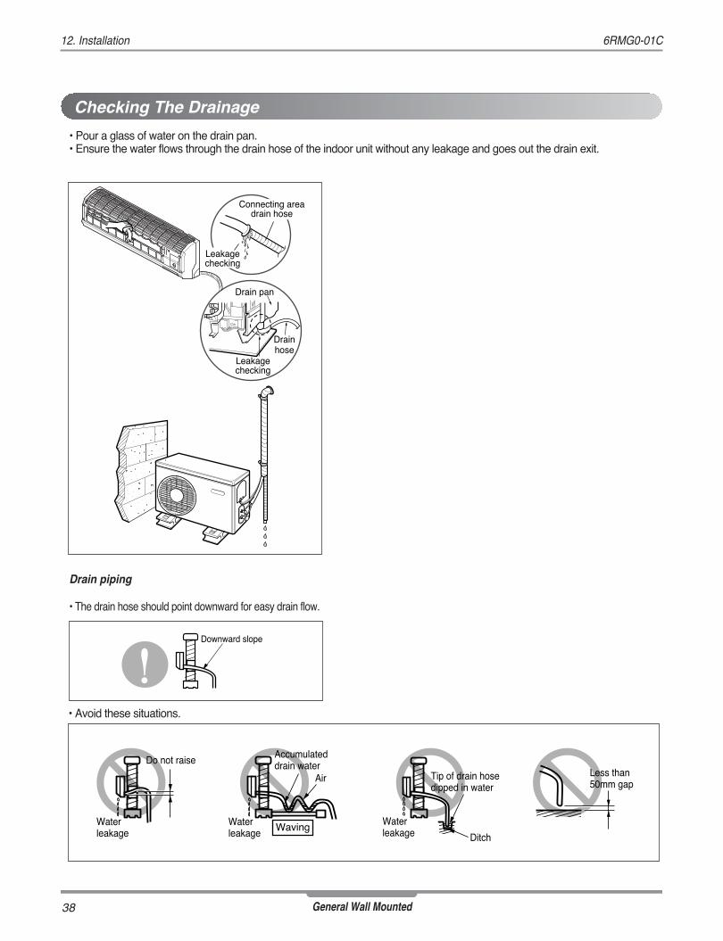
• Pour a glass of water on the drain pan.• Ensure the water flows through the drain hose of the indoor unit without any leakage and goes out the drain exit.
Drain piping
• The drain hose should point downward for easy drain flow.
• Avoid these situations.
Drain pan
Drainhose
Leakagechecking
Connecting areadrain hose
Leakagechecking
Downward slope
Do not raiseAccumulateddrain water
Tip of drain hose dipped in water
Air
WavingWaterleakage
Waterleakage Ditch
Less than 50mm gap
Waterleakage
Checking The Drainage

39
12. Installation6RMG0-01C
General Wall Mounted
Form the piping by wrapping the connecting portion ofthe indoor unit with insulation material and secure itwith two kinds of vinyl tapes.• If you want to connect an additional drain hose, the end of
the drain outlet should be routed above the ground. Securethe drain hose appropriately.
In cases where the outdoor unit is installed below theindoor unit perform the following.• Tape the piping, drain hose and connecting cable from
down to up.• Secure the tapped piping along the exterior wall using
saddle or equivalent.
Taping
Drainhose
Pipings
Connectingcable
Trap is required to prevent waterfrom entering into electrical parts.
Seal small openingsaround pipings with agum type sealer.
In cases where the Outdoor unit is installed above theIndoor unit perform the following.• Tape the piping and connecting cable from down to up.• Secure the taped piping along the exterior wall. Form a trap
to prevent water entering the room.• Fix the piping onto the wall by saddle or equivalent.
Seal a small opening around the pipings with gum type sealer.
Trap
Trap
Forming The Piping

40
12. Installation 6RMG0-01C
General Wall Mounted
Lo Hi
Indoor unit
Outdoor unit
Manifold valve
Charge hose
Nitrogen gascylinder(in verticalstanding position)
Pressure gauge
Air and moisture remaining in the refrigerant system have undesirable effects as indicated below.• Pressure in the system rises.• Operating current rises.• Cooling(or heating) efficiency drops.• Moisture in the refrigerant circuit may freeze and block capillary tubing.• Water may lead to corrosion of parts in the refrigeration system.Therefore, the indoor unit and tubing between the indoor and outdoor unit must be leak tested and evacuated to remove anynoncondensables and moisture from the system.
Preparation
• Check that each tubing(both liquid and gas side tubes)between the indoor and outdoor units have been prop-erly connected and all wiring for the test run has beencompleted. Remove the service valve caps from boththe gas and the liquid side on the outdoor unit. Notethat both the liquid and the gas side service valves onthe outdoor unit are kept closed at this stage.
Leak test
• Connect the manifold valve(with pressure gauges) anddry nitrogen gas cylinder to this service port withcharge hoses.
• Pressurize the system to no more than 150 P.S.I.G. withdry nitrogen gas and close the cylinder valve when thegauge reading reached 150 P.S.I.G. Next, test for leakswith liquid soap.
• Do a leak test of all joints of the tubing(both indoor and out-door) and both gas and liquid side service valves.Bubbles indicate a leak. Be sure to wipe off the soap with aclean cloth.
• After the system is found to be free of leaks, relieve the nitro-gen pressure by loosening the charge hose connector at thenitrogen cylinder. When the system pressure is reduced tonormal, disconnect the hose from the cylinder.
Be sure to use a manifold valve for airpurging. If it is not available, use a stopvalve for this purpose. The "Hi" knob ofthe manifold valve must always be keptclose.
To avoid nitrogen entering the refrigerant system ina liquid state, the top of the cylinder must be higherthan its bottom when you pressurize the system.Usually, the cylinder is used in a vertical standingposition.
CAUTION
CAUTION
Air Purging
Air purging With Vacuum Pump

41
12. Installation6RMG0-01C
General Wall Mounted
Evacuation
• Connect the charge hose end described in the preced-ing steps to the vacuum pump to evacuate the tubingand indoor unit.Confirm the "Lo" knob of the manifold valve is open.Then, run the vacuum pump. The operation time for evacuation varies with tubinglength and capacity of the pump. The following tableshows the time required for evacuation.
• When the desired vacuum is reached, close the "Lo"knob of the manifold valve and stop the vacuum pump.
Finishing the job
• With a service valve wrench, turn the valve stem of liq-uid side valve counter-clockwise to fully open the valve.
• Turn the valve stem of gas side valve counter-clockwise tofully open the valve.
• Loosen the charge hose connected to the gas side serviceport slightly to release the pressure, then remove the hose.
• Replace the flare nut and its bonnet on the gas side serviceport and fasten the flare nut securely with an adjustablewrench. This process is very important to prevent leakagefrom the system.
• Replace the valve caps at both gas and liquid side servicevalves and fasten them tight.
This completes air purging with a vacuum pump. The air conditioner is now ready to test run.
(1) Remove the caps from the gas side and liquid sidevalves.
(2) Remove the service-port cap from the gas sidevalve.
(3) To open the gas side valve turn the valve stemcounterclockwise approximately 90°, wait for about2~3 seconds, and close it.
(4) Apply a soap water or a liquid neutral detergent onthe indoor unit connection or outdoor unit connec-tions by a soft brush to check for leakage of theconnecting points of the piping.
(5) If bubbles come out, the pipes have leakage.
Soap water method
Suction Line
Evaporator Line
Cap
Hexagonal wrench
3-way valve(Open)
3-way valve(Close)
Required time for evacuation when 30 gal/h vac-uum pump is used
10 min. or more 15 min. or more
If tubing length is lessthan 10m (33 ft)
if tubing length is longerthan 10m (33 ft)
Indoor unit
Outdoor unit
Lo Hi
Manifold valve
Vacuum pump
Pressure gauge
Open Close

42
13. Installation Guide at the Seaside13. Installation Guide at the Seaside 6RMG0-01C
General Wall Mounted
1. Air conditioners should not be installed in areas where corrosive gases, such as acid or alkaline gas, are produced.2. Do not install the product where it could be exposed to sea wind (salty wind) directly. It can result corrosion
on the product. Corrosion, particularly on the condenser and evaporator fins, could cause product malfunc-tion or inefficient performance.
3. If outdoor unit is installed close to the seaside, it should avoid direct exposure to the sea wind. Otherwise itneeds additional anticorrosion treatment on the heat exchanger.
1. If you can’t meet above guide line in the seaside installation, please contact LG Electronics for the additional anticorrosion treatment.2. Periodic ( more than once/year ) cleaning of the dust or salt particles stuck on the heat exchanger by using water
Selecting the location(Outdoor Unit)1) If the outdoor unit is to be installed close to the seaside, direct exposure to the sea wind should be avoided.
Install the outdoor unit on the opposite side of the sea wind direction.
2) In case, to install the outdoor unit on the seaside, set up a windbreak not to be exposed to the sea wind.
3) Select a well-drained place.
• It should be strong enough like concrete to preventthe sea wind from the sea.
• The height and width should be more than 150% ofthe outdoor unit.
• It should be keep more than 70 cm of spacebetween outdoor unit and the windbreak for easyair flow.
Sea wind Sea wind
Sea wind
Windbreak
CAUTION

P/No.: 3828A20801X
Air Conditioner20 Yeouido-dong, Yeongdeungpo-gu,Yeouido P.O.Box 335 Seoul, 150-721, Korea.http://www.lgeaircon.com
All rights reservedPrinted in Korea Oct/2010The specifications, designs, andinformation in this brochure are subject to change without notice.
The air conditioners manufactured by LG have received ISO9001 certificate for quality assurance and ISO14001 certificate for environmental management system.