Embed Size (px)
Citation preview
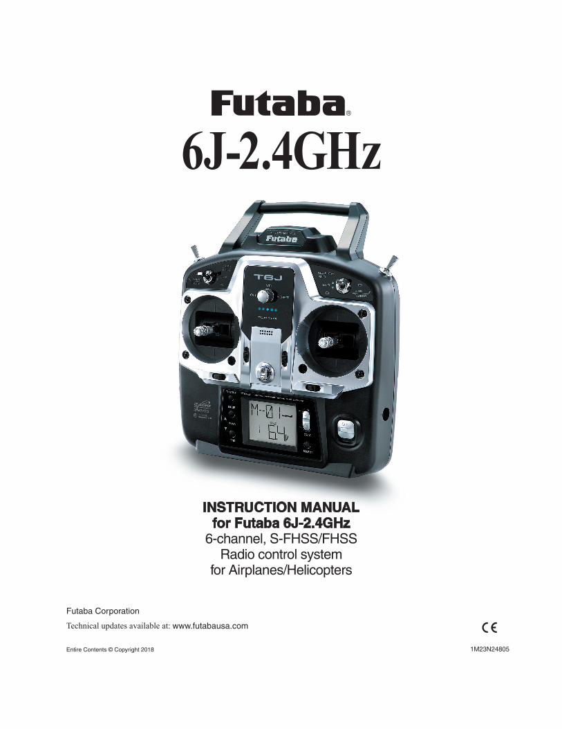
INSTRUCTION MANUALfor Futaba 6J-2.4GHz
6-channel, S-FHSS/FHSSRadio control system
for Airplanes/Helicopters
1M23N24805
Futaba Corporation
Technical updates available at: www.futabausa.com
Entire Contents © Copyright 2018
6J-2.4GHz

2
Introduction .............................................................3
Service ......................................................................3
Usage Precautions: ..................................................4
...................................4
Introduction to the 6J- 2.4GHz System .................6
Transmitter controls ...............................................6
Radio Installation ....................................................9
Receiver Installation: ............................................10
Receiver and Servo Connections .........................14
Charging NiCd/NiMH batteries ..........................16
Liquid Crystal Display (LCD) and Programming Controls ..................................................................18
Programming the T6J-2.4GHz Radio .................19
(Common Functions)
Parameter (PARA) .............................................20
Model Select Function (MODL)........................20
Model Name function ........................................21
Data Reset function (REST) ..............................22
ACRO/HELI Model type select function (TYPE) . ...........................................................................23
Transmission Mode Selection (MODE) ............24
Throttle-Cut Function (TCUT) ..........................25
Battery F/S Fail Safe (S-FHSS Mode only) ......26
Servo Reversing (REVR) ..................................27
Dual Rates (ACRO) ..........................................28
Exponential Settings (EXPO) – (ACRO) ..........29
Dual Rates (HELI) ............................................30
Exponential Settings (EXPO) - HELI ................32
End Point Adjustment (EPA) .............................33
Trim Settings (TRIM) ........................................34
Sub-Trims (STRM) ............................................36
(Airplane Only Programming)
Programmable Mix 1 and 2 (PMX 1 and PMIX 2) (ACRO only) .....................................................37
Wing Type Selection- (ACRO only) ..................38
Flaperon mixing (FLPR)- (ACRO only) ...........39
Flap trim (FLTR)- (ACRO only) .......................41
V-tail mixing (V-TL)- (ACRO only) .................42
Elevon mixing (ELVN)- (ACRO only) ..............43
Throttle Curve (T-CV)- (ACRO only) ...............44
Pitch Curve (P-CV)- (ACRO only) ...................45
(Helicopter Only Programming)
Normal throttle curve function (N-TH)- (HELI only)- ..................................................................47
Normal pitch curve (N-PI)-(HELI only) ............48
Idle Up throttle curve function (I-TH)- (HELI Only) ..................................................................49
Pitch Curve Idle UP (I-PI) - (HELI only) ..........51
Throttle hold function (HOLD)- (HELI only) ...52
Pitch Curve Hold (H-PI)- (HELI only) ..............53
Revolution Mixing (REVO) - (HELI only) .......54
Gyro mixing function (GYRO)-(HELI only) ....55
Swash to throttle mixing (SW-T)-(HELI only)..57
Swash Ring (RING) ...........................................57
Swashplate type selection and Swash AFR (SWSH) - (HELI only) ......................................58
Swashplate AFR (Adjustable Function Rate) - (HELI only) .......................................................60
Delay (DELY)- (HELI only) ..............................61
Hovering Pitch (HOVP)- (HELI only) ..............62
(Other Programming function)
Fail Safe (F/S) ....................................................63
TRNR Trainer function ......................................64
TIMER ...............................................................67
Flow Chart ACRO Mode Functions ....................70
Flow Chart HELI Mode Functions .....................72
Adjustable length control sticks ..........................74
Changing the T6J Stick Mode .............................74
Flying Safety Guidelines .......................................75
Charge the batteries ..............................................75
Flight Preparation .................................................76
Check the controls .................................................76
GLOSSARY ...........................................................77
Model Data Recording Sheet (ACRO) ................96
Model Data Recording Sheet (HELI) ..................97
TABLE OF CONTENTS
3
INTRODUCTION
Thank you for purchasing the Futaba 6J digital proportional R/C airplane/helicopter system. This radio has been designed and manufactured to provide you with many, many years of modeling enjoyment and fun.
the more advanced radios. In either case, to make the best use of the Futaba 6J system, and to operate it safely, you should carefully read the instructions in their entirety prior to operation.
Every modeler has their own personal preferences on the proper steps to set-up and program their models.
function list of the system. If you wish to follow your own personal preference on setting up a model, please feel free to do so keeping in mind that some programming options will interact with others. For example,
Suggestion: If, while reading the instructions, you are unclear of some of the procedures or functions
explained again later in an alternate manner which will clarify the procedure or function. Another alternative is to connect the battery, servos, receiver, etc. to simulate your aircraft and actually program the radio
this alternate method of familiarizing yourself with your radio, please ensure that your aircraft can not cause harm to yourself or others by disabling it accordingly.
Service
(USA only)
If any difficulties are encountered while setting up or operating your system, please consult the
may also refer to your hobby dealer, or contact the Futaba Service Center at the web site, email address, fax number, or telephone number below.
https://www.futabausa.com/E-mail: [email protected]
FAX:1-256-461-1059Phone:1-256-461-9399
As of this writing, the Futaba Service Center assistance is available from 8:00 AM to 5:00 PM Central Standard Time, Monday through Friday. This is subject to change at any time, however.
If you are unable to resolve the difficulty, pack
the system in its original packaging. Please also include a note that provides a thorough and accurate description of the difficulties experienced. Please include the following information in your note:
• Symptoms • Inventory of enclosed items • The items that require repair • Contact information-name, address, telephone number and email address • If items are to be considered for warranty repair, please also include a copy of the proof of purchase or purchase receipt
The equipment should be sent to the Futaba Service Center at the address below:
FUTABA Corporation of America 2681 Wall Triana Hwy Huntsville, AL 35824,
U.S.A.

4
This product is to be used for the flying of radio controlled models only. Futaba is not responsible for the results of use of this product by the customer or for any alteration of this product including modification or incorporation into other devices by third parties.
(USA only)
Please protect the environment by disposing of rechargeable batteries responsibly. Throwing rechargeable batteries into the trash or municipal waste system is illegal in some areas. Call 1-800-BATTERY for information about NiCd battery recycling in your area.
USAGE PRECAUTIONS:
1) Please obey all regulations to enjoy safe modeling.
2) Please keep the model in sight at all times as large objects can negatively impact the RF signal. Please keep in mind that objects such as wire fences and wire mesh will also cause degradation of the RF signal.
CONTENTS AND SPECIFICATIONS
Transmitter: T6J- 2.4GHz • 6-Channel - 2.4GHz S-FHSS transmitter
(Up to 4-Channel at 2.4GHz FHSS system) • Transmitting on 2.4GHz band • Operating system: 2-stick, 6-channel system • Power supply: 4-AA 1.2V Dry Cell batteries; 4.8V total (sold separately) • Current drain: 120mA
Receiver: R2006GS • 6-Channel - 2.4GHz S-FHSS receiver
(Up to 4-Channel at 2.4GHz FHSS system) • Receiving on 2.4GHz band • Power requirement: 4.8 ~ 7.4 volts (shared with servos)(*1) • Current drain: 80mA (at no signal) • Size: 1.70 x 0.98 x 0.35 inches (43.1x 25.0x 8.8 millimeters) • Weight: 0.30 Ounces (8.5 grams)
(*1) Note: Never use dry cell batteries for the R2006GS receiver as this may cause difficulties with the
GLOSSARY
It will be helpful to understand the following terms before reading the rest of this manual. The terms are not in alphabetical order, but are in a logical order that prepares the reader for better understanding the next term. For additional terminology, please refer to the complete glossary that is located elsewhere in this manual.

5
Reversing (servo reversing):installation by allowing the user to electronically set the proper response direction for each servo.
Throw: When speaking of a control surface (such as an elevator or aileron), the throw is the distance that the surface moves. Control surface throw is usually measured at the trailing edge (back) of the control surface and is expressed in inches or millimeters. The model in the diagram has 1/2” (13mm) of up elevator throw. Please note that throw might also refer to the distance that a servo arm, wheel, etc. travels.
Dual Rate (D/R): On the 6J 2.4GHz the dual rate switch allows you to instantly
maneuvers such as hovering, or when landing the model and the speed is slower thereby the model may not be as sensitive. It is also important to note that lower rates are better for beginners, who tend to over-control
End Point Adjustments (EPA): Sets the overall, maximum distance that the servo rotates in either direction.
Exponential (EXPO): Normally, servos respond proportionally to control stick input from the transmitter. That is, if the stick is moved halfway, the corresponding servo will also move halfway. However, with exponential, the servo can be made to move more, or less, than the relative stick movement. Generally speaking, exponential is used to lessen, or lower, the servo movement. Exponential is commonly used to
Control response is milder around half-stick, but becomes increasing stronger as stick travel approaches 100%. Exponential is great for aerobatics and trouble situations.
Please note it is important to remember that dual rates adjust the amount of servo travel whereas the exponential adjustments determine where most of the travel will occur.
Mixing: Two (or more) servos may be made to operate together either by mechanically joining their leads
Y-connector, when servos are mixed electronically they can be made to move in opposition. Additionally, it is possible to adjust the ratio at which the two channels are mixed.
the model and determining the direction and amount of elevator throw required to correct for this change,
6
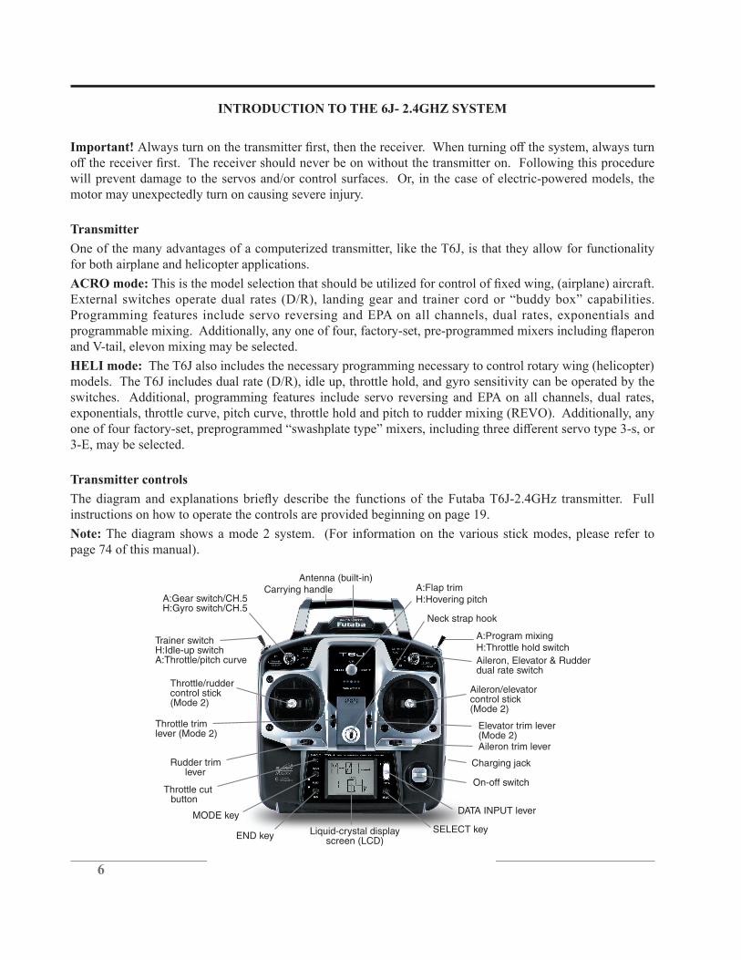
Aileron, Elevator & Rudderdual rate switch
Antenna (built-in)
A:Gear switch/CH.5H:Gyro switch/CH.5
A:Program mixingH:Throttle hold switch
Carrying handle
Liquid-crystal displayscreen (LCD)
Throttle/ruddercontrol stick(Mode 2)
MODE key
END key
Trainer switchH:Idle-up switchA:Throttle/pitch curve
Neck strap hook
Charging jack
On-off switch
Rudder trim lever
Throttle trimlever (Mode 2)
DATA INPUT lever
SELECT key
Aileron trim lever
Elevator trim lever(Mode 2)
Aileron/elevatorcontrol stick(Mode 2)
Throttle cutbutton
A:Flap trimH:Hovering pitch
INTRODUCTION TO THE 6J- 2.4GHZ SYSTEM
Important!
will prevent damage to the servos and/or control surfaces. Or, in the case of electric-powered models, the motor may unexpectedly turn on causing severe injury.
Transmitter
One of the many advantages of a computerized transmitter, like the T6J, is that they allow for functionality for both airplane and helicopter applications.
ACRO mode:
Programming features include servo reversing and EPA on all channels, dual rates, exponentials and
and V-tail, elevon mixing may be selected.
HELI mode: The T6J also includes the necessary programming necessary to control rotary wing (helicopter) models. The T6J includes dual rate (D/R), idle up, throttle hold, and gyro sensitivity can be operated by the switches. Additional, programming features include servo reversing and EPA on all channels, dual rates, exponentials, throttle curve, pitch curve, throttle hold and pitch to rudder mixing (REVO). Additionally, any
3-E, may be selected.
Transmitter controls
instructions on how to operate the controls are provided beginning on page 19.
Note: The diagram shows a mode 2 system. (For information on the various stick modes, please refer to page 74 of this manual).

7
Descriptions:
Note: A: indicates functions that are only found when the T6J is in the ACRO (airplane) mode. H: indicates functions that are only found when the T6J is in the HELI (helicopter) mode. If neither an A: or H: is indicated the function is applicable to both ACRO and HELI modes.
Aileron, Elevator and Rudder dual rate switch: use this switch to select between two aileron, elevator and rudder control throw settings. The throws can be set up however you prefer. Generally speaking, when the
applicable. Note: The T6J allows modelers to assign the dual rates to various switches. Please refer to the dual rate section of this manual for additional information.
A: Flaps/channel 6- This switch operates the servo connected to channel six in the receiver. If your model
H: Throttle hold switch-throttle stick. It is commonly used to practice autorotation skills for helicopter pilots.
Neck strap hook:strap allows the transmitter to hang around the neck and relieve some of the weight from your hands.
Aileron/elevator control stick: Operates the servos connected to channel 1 (aileron) and channel 2 (elevator) in the receiver. (Mode 2)
Trim levers (all): Used to shift the neutral or center position of each servo as labeled in the diagram. Once any trim lever is operated, the trim position is displayed on the LCD screen.
Note:
Charging jack: Port used for charging the transmitter batteries (if applicable). The T6J does not include rechargeable transmitter batteries or the AC charger. However, these items are available separately at your local hobby shop, if desired.
DATA Input Lever: Used to change the values of the various functions displayed on the LCD screen.

8
Liquid Crystal Display: Commonly referred to as LCD, this is the screen of the transmitter that displays the programming modes, values entered, etc.
MODE key:
SELECT key: Used to display the values for the current function.
Throttle cut button: This button activates the throttle cut function and is used to fully close the carburetor
Throttle/Rudder control stick: Operates the servos connected to channel 3 (throttle) and channel 4 (rudder) in the receiver. (Mode 2)
Trainer switch: Operates the trainer functions. To operate as a trainer switch, the transmitter must be connected to another transmitter via a trainer cord (sold separately). See page 64 for more information on this feature.
H: Idle Up switch:
A: Retractable landing gear switch/channel 5: This switch operates the servo connected to channel 5 in the receiver. If your model has retractable landing gear, this is the control used to extend and retract the gear.
H: Gyro switch/channel 5:
Ratchet plate for airplane
Ratchet plate for helicopter
Generally speaking, helicopter pilots prefer a smooth operation of the throttle stick rather than the ratcheting operation commonly used by fixed wing pilots. The procedure below will allow modelers to change from this ratcheting operation to the smoother throttle stick operation.
1) Open the battery cover on the back of the transmitter and remove the transmitter battery, or batteries.
2) Unplug the battery connection on the left side of the battery case.
3) Remove the four transmitter rear case screws and remove the rear case.
4) Change the ratchet plate on the gimbal section to the smooth ratchet plate for helicopter use.

9
RADIO INSTALLATION
Follow these guidelines to properly mount the servos, receiver and battery.
• Make certain that the alignment tab on the battery, switch and servo connectors are oriented correctly and
them in. When unplugging connectors never pull directly on the wires. Instead, pull directly on the plastic connectors. Doing so will prevent any damage to the wires.
•of servo extensions which may be purchased separately for this application.
ServoRubber
grommet ServoRubber
grommet • Always mount the servos with the supplied rubber grommets. Do not over-tighten the screws. No part of the servo casing should contact the mounting rails, servo tray or any other part of the airplane/helicopter structure. If they do so, vibration will be transmitted to the servo itself causing premature wear and/or servo failure.
• Note the small numbers (1-4) molded into each arm of the Futaba 4-arm servo arms. The
used to correct slight manufacturing deviances between servos and ensure the proper geometric set-up for the aircraft.
• To center the servos, connect them to the receiver and turn on the transmitter followed by the receiver. Center the trims on the
degrees) to the pushrod when placed on the servo.
• After the servos are installed, operate each servo over its full travel and check that the pushrods and servo arms do not bind or contact each other. Also, make sure that the controls do not require excess force to operate. If there is any objectionable buzzing sound coming from a servo, there is probably too much
• Use the mounting plate from the receiver on/off switch as a template for the cutout and screw holes.
a full range of motion from the switch in both directions. Be certain that the switch moves without and
• When you install the switch harness in the helicopter, please use the switch cover. Generally, sandwich

10
Fasten about 5-10cm from the servo outlet so that the lead wire is neat.
Margin in the lead wire.
• To prevent the servo lead wires from being broken by vibration during flight, provide a bit of slack so that the wire is not pulling against the servo or connector going to the receiver. In
IMPORTANT: In order to maximize the performance and enjoyment of the Futaba T6J transmitter, please read this section carefully and completely.
Receiver Installation:
• In order to obtain the best possible performance from your 2.4GHz aircraft receiver, we have developed the following guidelines and suggestions.
Antenna
*Must be kept as straight as possible.
Coaxial cable
• The R2006GS has two antennas. In order to maximize signal reception and promote safe modeling Futaba has adopted a diversity antenna system. This allows the receiver to obtain RF
• To obtain the best results from the diversity function, please refer to the following instructions:
The two antennas must be kept as straight as possible. Failure to do so might result in reduced operational range of the model.
Ideally, the two antennas should be placed at 90 degrees to each other. However, the most critical aspect is to keep the antennas away from each other as much as possible.
Larger models can have large metal objects that can attenuate the RF signal. In this case the antennas should be placed at both sides of the model. Then the best RF signal
The antennas should be kept away from conductive materials, such as metal and carbon by at least half-inch. The coaxial part of the antennas does not need to follow these guidelines, but do not bend in a small radius.
Antenna Antenna
11
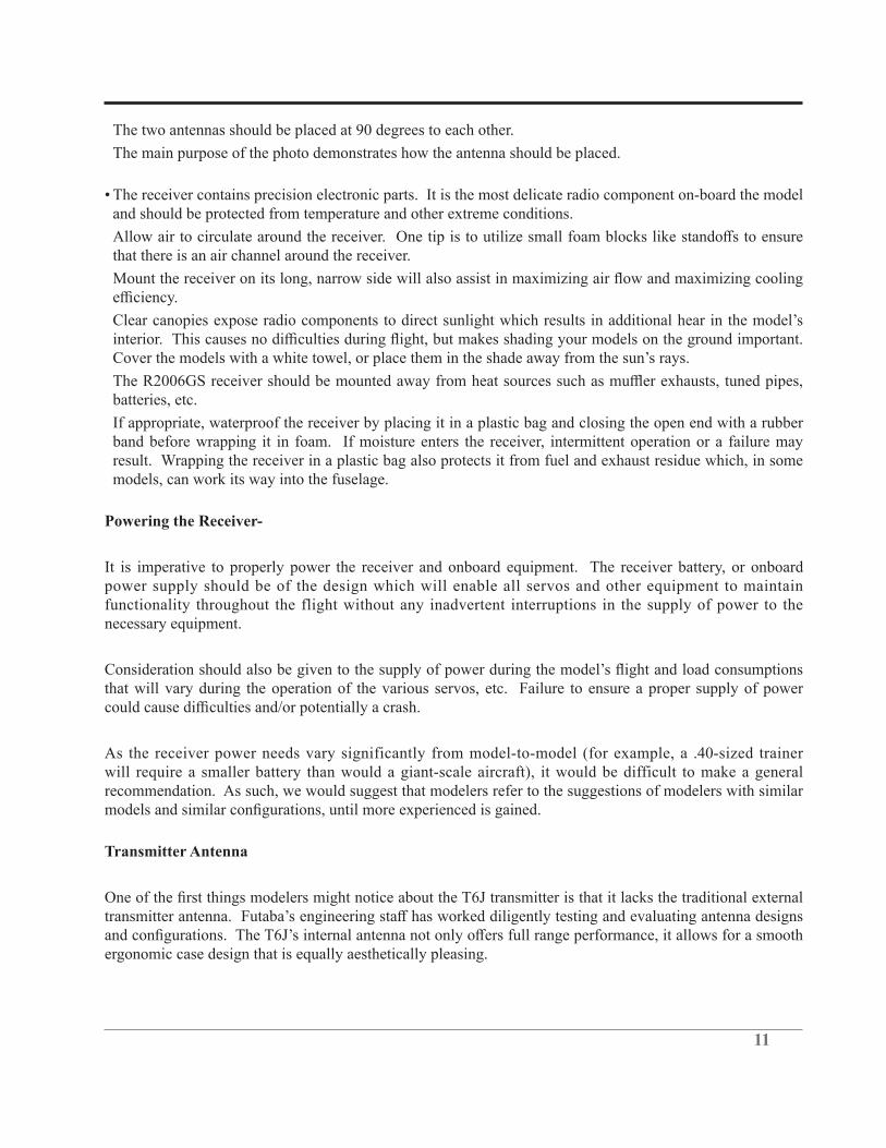
The two antennas should be placed at 90 degrees to each other.
The main purpose of the photo demonstrates how the antenna should be placed.
• The receiver contains precision electronic parts. It is the most delicate radio component on-board the model and should be protected from temperature and other extreme conditions.
that there is an air channel around the receiver.
batteries, etc.
If appropriate, waterproof the receiver by placing it in a plastic bag and closing the open end with a rubber band before wrapping it in foam. If moisture enters the receiver, intermittent operation or a failure may result. Wrapping the receiver in a plastic bag also protects it from fuel and exhaust residue which, in some models, can work its way into the fuselage.
Powering the Receiver-
It is imperative to properly power the receiver and onboard equipment. The receiver battery, or onboard power supply should be of the design which will enable all servos and other equipment to maintain functionality throughout the flight without any inadvertent interruptions in the supply of power to the necessary equipment.
that will vary during the operation of the various servos, etc. Failure to ensure a proper supply of power
As the receiver power needs vary significantly from model-to-model (for example, a .40-sized trainer will require a smaller battery than would a giant-scale aircraft), it would be difficult to make a general recommendation. As such, we would suggest that modelers refer to the suggestions of modelers with similar
Transmitter Antenna
ergonomic case design that is equally aesthetically pleasing.

12
RANGE CHECK THE RADIO
adequate operational range.
check. During this mode, the RF power is reduced in order to test the operational range of the T6J.
the full range mode. In most instances, 90 seconds is more than an adequate amount of time to allow for a complete range check.
To activate the Power Down Mode and Perform A Range Check:
switch on. When this mode is active the blue LED on the front of the transmitter will begin blinking and
Down Mode”.
Audibly, the transmitter will beep one time every three seconds until it reaches the 90 second time limit. At which time the transmitter will beep two times and then return to the full power mode.
simultaneously operating the controls. Have an assistant stand by the model and
be able to walk approximately 30-50 paces from the model without losing control.
servo connections or binding pushrods. Also be certain that the battery has been fully charged.

13
LINKING PROCEDURE
link is made, the ID code is stored in the receiver and no further linking is necessary unless the receiver is to be used with another transmitter. In the case of this T6J transmitter/receiver set, the linking has already been completed at the factory. However, it is always a good safety precaution to perform this linking procedure once again, regardless.
existing transmitter. In order to do so, follow the procedure below:
1) Place the transmitter and the receiver close to one another. Generally speaking, as long as the transmitter
2) Turn on the transmitter.
3) Check the LED that is located on the face of the T6J transmitter. When the blue LED is on, and solid (no blinking), the RF signal is being transmitted.
4) With power connected to the receiver turn on the receiver. The LED on the face of the receiver will begin blinking.
switch on the receiver for more than one second. At this point, the receiver/transmitter will start the linking operation.
the servos will now operate by your transmitter. Please refer to the table below for the LED status of the
No signal reception Red: OnReceiving signals Green: OnReceiving signals, but ID is unmatched Green: BlinkUnrecoverable failure (EEPROM, etc.) Red and Green turn on alternately

14
RECEIVER AND SERVO CONNECTIONS
Connect the servos to the receiver to perform the functions indicated:
Receiveroutput channel
Aircraft (ACRO) Helicopter (HELI)
1elevon (for tailless models)
Aileron
2Elevator –or- left ruddervator (for V-tail models) –or- left elevon (for tailless models)
Elevator
3 Throttle Throttle
4Rudder –or- right ruddervator (for V-tail models)
Rudder
5 Retractable landing gear Gyro sensitivity6 Pitch
B colored connector should be inserted into the receiver)
colored connector should be inserted into the receiver)
SwitchHarness
To Battery
ChargingJack
(Black)
Aileron Servo(CH1)
OptionalGyro
System
Elevator Servo (CH2)
Throttle Servo(CH3)
Rudder Servo
Rudder (CH4)
Pitch Servo(CH6)
The diagram shown is for helicopter models only. It is necessary to buy an additional gyro separately.
Gyro sensitivity (CH5)
Receiver
SwitchHarness
To Battery
ChargingJack
(Black)
Aileron Servo(CH1)
Elevator Servo(CH2)
Throttle Servo(CH3)
Rudder Servo(CH4)
Gear Servo(CH5)
Flap Servo(CH6)
The diagram shown is for aircraft models only. Additional servos may have to be purchased separately.
(CH1)
(CH6)(CH1)
(CH2)
(CH4)
(CH2)
(CH4)
Flaperon Mode (Dual AileronServo, CH1 & 6)
Independent Aileron & Flap
(CH6)
(Red)
(Red)Receiver
NOTE: NEVER use dry battery for R606FS as it cause malfunction.
NOTE: NEVER use dry battery for R606FS as it cause malfunction.

15
ALARMS AND WARNINGS
For example, whether you are in airplane or helicopter mode, should the batteries drop lower than the recommended safe voltage, an alarm will sound. When in the helicopter mode there are several additional warnings/alarms that may sound: stick position, throttle hold and/or idle up activated.
These are built-in safety features to ensure the longevity of your model and your enjoyment of the hobby. We strongly suggest adhering to the warnings accordingly.
Transmitter Battery voltage-
The T6J transmitter offers a programmable low voltage alarm that warns modelers when the transmitter
To set the Transmitter Battery Voltage Alarm-
1) Press and hold the MODE and END buttons while simultaneously turning on the transmitter.
2) Press the DATA INPUT lever upward or downward to select the voltage at which the Battery Voltage Alarm will sound. If using four AA Alkaline (dry cell) batteries,
battery, select the 5.0V setting.
hold or when the T6J is transmitting in the FHSS mode.
Stick Position Alarm-
position when the transmitter is powered up, or turned on. If the throttle stick is not at the idle position, the transmitter will sound an audible alarm, and the screen will display a visual warning as well.
Move the throttle position to the lowest position in order to silence this alarm accordingly.
Throttle Hold and Idle Up Alarm (HELI only).

16
position alarm mentioned above, the T6J will sound an audible warning and display a visual warning on the screen also.
These warning signals will continue until the switch(es) are returned to their off positions.
BATTERY CHARGING PROCEDURES AND PRECAUTIONS
NiCd/NiMH battery pack, both available separately. The transmitter batteries used are a matter of personal preference.
AA Alkaline batteries are available at any local hobby shop, grocery store, etc. A NiCd/NiMH battery pack will need to be purchased from a hobby shop.
Charging NiCd/NiMH batteries
As noted above, the T6J transmitter will function with four dry cell batteries, however, some modelers will opt to purchase a NiCd/NiMH battery pack and charger for use with this transmitter.
Failure to exercise caution while using this product and to comply with warnings pertaining to the charging
Whether you choose NiCd (nickel cadmium, pronounced nI-kad) or NiMH (nickel metal hydride) batteries, these packs require special care and charging. Read the charging instructions carefully.
NOTE: The batteries are generally supplied partially charged but will require a full, overnight charge before
to the charge jack in the right side of the transmitter case. The receiver charging cord may be connected to
is preferred as there will be no need to disconnect the battery.
are being charged. Discharged batteries will take about 15 hours to fully charge. If using an aftermarket
not overcharge the batteries. NEVER charge the batteries at a rate higher than recommended by the manufacturer. Depending upon the battery cell construction, the batteries should also be discharged
17
causing a crash. To erase any potential memory, cycle the NiCd batteries by discharging, then charging
transmitter sticks until the servos are moving very slowly, indicating that the battery is discharged. Cycling should be done every one to two months, even during the winter or periods of long storage. If using a cycler with a readout, note the capacity after the batteries have been cycled. If there is a noticeable drop in capacity the batteries should be replaced.
Note: Charging your batteries with a Futaba A/C battery charger is always safe. However, fast charging with an aftermarket charger is acceptable as long as you know how to properly operate the charger. Never charge at a rate higher than suggested by the manufacturer. If not done correctly, fast charging can damage the batteries.
Battery Care and Precautions
and/or receiver battery packs. These are included to serve only as general guidelines, and are not intended to replace or supersede the information provided by the battery and/or charger manufacturer. For complete information, please refer to the instructions that are included with the battery pack(s) and/or chargers that accompany the products purchased.
• Do not allow children to charge battery packs without adult supervision. • Do not charge battery packs that have been damaged in any way. We strongly suggest frequent inspection of the battery packs to ensure that no damage has occurred. •and allow to cool. • • Do not deep cycle NiMH batteries as permanent damage could result. • Never charge batteries on a surface that may become hot, or may be impacted by the heat. • Immediately end the charging procedure if either the batteries or charger itself become overly hot. •packs with some voltage remaining on the cells (refer to battery supplier). • NiMH cells have a self-discharge rate of approximately 20-25% (compared to 15% for NiCd batteries). It is important to recharge NiMH batteries immediately prior to use. • Never connect the battery in reverse. Reverse connection will cause the battery to overheat or will damage the inside of the charger. • Do not add an additional charge after charging. • Never charge with a current exceeding the nominal capacity (lC) of the rechargeable battery. • If a battery is charged with a current exceeding 1C, the battery will overheat and deteriorate. • Do not connect two battery packs or more to one output terminal. • Avoid extremely cold and hot places and the direct sunlight when you charge batteries. • It is recommended to perform charging within the 10 ~ 30°C (50-85°F) range. Otherwise, it may cause abnormal charging and overheat.
18
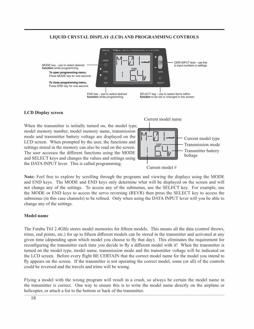
LIQUID CRYSTAL DISPLAY (LCD) AND PROGRAMMING CONTROLS
THR-CUT
MODE
FUNC
END SELECT
DATATo open programming menu; Press MODE key for one second.
To close programming menu; Press END key for one second.
MODE key - use to select desired function while programming
END key - use to select desired function while programming
SELECT key - use to select items within function to be set or changed in the screen
DATA INPUT lever - use this to input numbers or settings
LCD Display screen
Current model type
Current model #
Transmission mode
Current model name
Transmitter batteryboltage
When the transmitter is initially turned on, the model type, model memory number, model memory name, transmission mode and transmitter battery voltage are displayed on the LCD screen. When prompted by the user, the functions and settings stored in the memory can also be read on the screen.
and SELECT keys and changes the values and settings using the DATA INPUT lever. This is called programming.
Note: Feel free to explore by scrolling through the programs and viewing the displays using the MODE and END keys. The MODE and END keys only determine what will be displayed on the screen and will not change any of the settings. To access any of the submenus, use the SELECT key. For example, use the MODE or END keys to access the servo reversing (REVR) then press the SELECT key to access the
change any of the settings.
Model name
turned on the model type, model name, transmission mode and the transmitter voltage will be indicated on
could be reversed and the travels and trims will be wrong.
Flying a model with the wrong program will result in a crash, so always be certain the model name in the transmitter is correct. One way to ensure this is to write the model name directly on the airplane or helicopter, or attach a list to the bottom or back of the transmitter.

19
Transmitter Battery voltage
In addition to the model type, the LCD screen also displays the transmitter battery voltage. When the voltage goes below the Battery Low Voltage alarm setting, the
model before losing control.
NOTE: If the transmitter ever reaches this battery voltage alarm, land as soon as safely as possible. A
transmitter battery is slightly above the low voltage alarm setting.
Mixer Alert Warning (Heli Only)
If the transmitter is turned on with the throttle hold or idle up function switched on,
Backup error
The Backup error warning occurs when the transmitter memory is lost for any reason. If this occurs, all of the data will be reset when the power is turned on again.
when this message is displayed: all programming has been erased and is not available. Return your transmitter to Futaba service.
PROGRAMMING THE T6J-2.4GHZ RADIO
Anytime you wish to view or change any of the current settings in the transmitter, the programming mode
for approximately one second. Once in the program, the MODE or END key will be used to scroll through each of the available functions/features. The MODE key will scroll one direction while the END key will scroll in the opposite direction. Therefore, if when scrolling through the functions, if the modeler bypasses the desired function, press the opposite key to scroll back to the bypassed function. For example, if using the MODE key to scroll and the desired function is passed, press the END key to scroll to the desired function. The functions available for each model type are as follows:
Model type ACRO: Parameters- Data Reset / Model Type Select /Mode Select/Throttle Cut/Battery Fail Safe/Model Name, Model Select, Reversing, Dual Rates, Exponentials, End Point Adjustments, Trim, Sub-Trim, Programmable Mix 1, Programmable Mix 2, Flaperon Mixing, Flap Trim, V-Tail Mixing, Elevon Mixing, Throttle Curve, Pitch Curve, Failsafe, Trainer and Timer.
20
Model type HELI: Parameters- Data Reset / Model Type Select /Mode Select/Throttle Cut/Battery Fail Safe/Model /name, Model Select, Reversing, Dual Rates, Exponentials, End Point Adjustments, Trim, Sub-Trim, Normal Throttle Curve, Normal Pitch Curve, Idle Up Throttle Curve , Idle Up Pitch Curve, Throttle Hold, Throttle Hold Pitch Curve, Revolution Mixing, Gyro Sensitivity, Swash-Throttle Mixing, Swash Ring, Swash/AFR, Delay, Hovering Pitch, Failsafe, Trainer, and Timer.
The SELECT key will be used to view the settings, scroll through the options, etc. within the respective function. When a data change is actually required the DATA INPUT lever will be used to increase or decrease the value of the item displayed, thus making the change. The DATA INPUT lever, in some cases, may also be used to scroll through the various options and adjustments.
You can return to the home screen (where model name and battery voltage is displayed) by depressing and holding the END key for approximately one second.
Note: The functions are listed and described in the order that they appear in the transmitter. Read all the way
(ACRO).
Parameter (PARA)-
This includes model reset, aircraft type selection, mode selection, throttle cut and the battery fail safe selections.
Model Select Function (MODL)-
The model select function (MODL) is used to select amongst existing models or to create entirely new
model immediately after it is selected. To do so, please refer to the Model Name section of this manual.
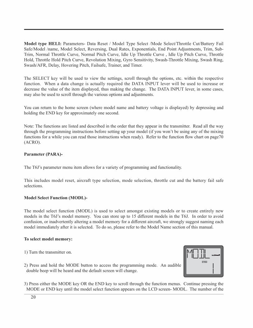
To select model memory:
1) Turn the transmitter on.
2) Press and hold the MODE button to access the programming mode. An audible double beep will be heard and the default screen will change.
3) Press either the MODE key OR the END key to scroll through the function menus. Continue pressing the MODE or END key until the model select function appears on the LCD screen- MODL. The number of the

21
current, active model will be blinking.
Note: If the END key is held down for 0.5 seconds, the transmitter will return to the default screen and will then display the current trim settings. When using the END key, press and release it to scroll through the options.
0.5 seconds until the desired model number appears. Release the DATA INPUT lever when the next model memory (MODL) appears on the LCD. Continue repeating this procedure until the desired model memory appears on the screen. Each time a new model memory is brought forth the T6J will emit a single audible beep.
5) With the desired mode memory (MODL) on the screen, all programming inputs from this point forward
Model Name function-
T6J allows up to four characters to be used in the naming designation for each model memory. By giving each model a name that is immediately recognizable, you can quickly select the correct model, and minimize
Note: In addition to the model naming designation, the model memory number will also be present on the home screen. This is an additional safety feature and will serve to also assist in model recognition.
Note: It is possible to change model names at any time, without impacting any of the other programming or settings that have been input.
To assign a model name to a model memory location:
1) Turn the transmitter on.
2) Press and hold the MODE button to access the programming mode. An audible double beep will be heard and the screen will display the model selection menu (MODL). The number of the current, active model will be blinking. Select the model you wish to name using the model memory select instructions above.
3) With the desired model memory on the LCD, press the SELECT key. The current model naming designation will begin blinking on the screen.
or downward until the desired character appears on the LCD.

22
5) Use the SELECT key to choose the next character.
6) Repeat this procedure for the remaining two spaces. When completed, press and hold the END button.
Data Reset function (REST)-
All the data for any model memory can be reset to the original factory defaults. Often this function is
Note: Data reset function only resets the defaults for the model that appears on screen. It does NOT reset the entire transmitter.
To reset data:
1) Turn the transmitter on. Ensure that the model on the home page is the one that is to be reset.
2) Press and hold the MODE button to access the programming mode.
3) Press either the MODE key OR the END key to scroll through the function menus. Continue pressing the MODE or END key until the parameter (PARA) submenu appears on screen.
4) Press the SELECT key until the model reset submenu (REST) is brought forth.
5) Press and hold the DATA INPUT upward or downward. The EXEC will begin
now been reset to the initial setting that is the default value set at the factory.
Note:
CAUTION: Resetting the current model memory will permanently erase ALL programming information for that model. The data cannot be recovered (unless you recorded it in written form on a Model Data Recording Sheet in the back of the manual). Do not reset the model unless you are certain you want to completely clear-out that model memory and start from scratch.
Note: The reset function will NOT impact any other models, or model memory other than that indicated on the LCD screen.
23
ACRO/HELI Model type select function (TYPE)-
The model type (TYPE) select function is used to determine whether the selected model memory will bring forth the airplane or helicopter programming. If, for example, the airplane (ACRO) is selected, the programming features and functions which are available will be airplane-related. If, however, a helicopter (HELI) is selected, the available features and functions will be directly related to helicopters.
ACRO:selection for further information, page 38).
HELI: Helicopter memory type (with three helicopter swashplate type. See Swashplate type selection for further information, page 58).
CAUTION:
CAUTION: When changing model types (e.g., from airplane to helicopter), the current programming will be lost and will be rewritten to the factory default settings for the new model type selected. As such, please select a new model memory when creating a new model in the transmitter.
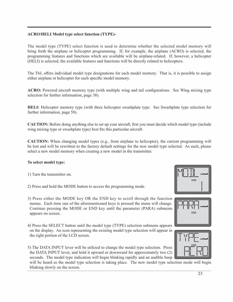
To select model type:
1) Turn the transmitter on.
2) Press and hold the MODE button to access the programming mode.
3) Press either the MODE key OR the END key to scroll through the function menus. Each time one of the aforementioned keys is pressed the menu will change. Continue pressing the MODE or END key until the parameter (PARA) submenu appears on screen.
4) Press the SELECT button until the model type (TYPE) selection submenu appears on the display. An icon representing the existing model type selection will appear in the right portion of the LCD screen.
5) The DATA INPUT lever will be utilized to change the model type selection. Press the DATA INPUT lever, and hold it upward or downward for approximately two (2) seconds. The model type indication will begin blinking rapidly and an audible beep will be heard as the model type selection is taking place. The new model type selection mode will begin blinking slowly on the screen.
24
Note: HELI indicates that the T6J will utilize the helicopter programming and functionality. ACRO represents the airplane model type selection.
Transmission Mode Selection (MODE)-
The T6J offers two different mode transmission selections: S-FHSS and FHSS. The R2006GS which accompanies the T6J is compatible with either the S-FHSS or FHSS settings and adjusts automatically to the signals from the transmitter, accordingly.
Note:
until the cycling of the power has taken place.
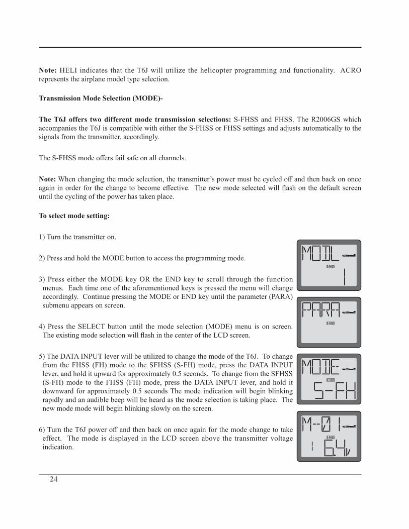
To select mode setting:
1) Turn the transmitter on.
2) Press and hold the MODE button to access the programming mode.
3) Press either the MODE key OR the END key to scroll through the function menus. Each time one of the aforementioned keys is pressed the menu will change accordingly. Continue pressing the MODE or END key until the parameter (PARA) submenu appears on screen.
4) Press the SELECT button until the mode selection (MODE) menu is on screen.
5) The DATA INPUT lever will be utilized to change the mode of the T6J. To change from the FHSS (FH) mode to the SFHSS (S-FH) mode, press the DATA INPUT lever, and hold it upward for approximately 0.5 seconds. To change from the SFHSS (S-FH) mode to the FHSS (FH) mode, press the DATA INPUT lever, and hold it downward for approximately 0.5 seconds The mode indication will begin blinking rapidly and an audible beep will be heard as the mode selection is taking place. The new mode mode will begin blinking slowly on the screen.
effect. The mode is displayed in the LCD screen above the transmitter voltage indication.

25
Throttle-Cut Function (TCUT)-
engine when lowering the throttle stick all the way (such as when coming in for a landing). When used in electric-powered applications, it will prevent inadvertent operation of the speed control.
is to be used for internal combustion engines. The electronic speed control (ESC) is to be used for electric-powered models.
To program the Throttle-Cut (TCUT) Function (Normal):
1) At the model select screen, press either the MODE or END button until the PARA (Parameter) screen appears.
2) Press SELECT until the TCUT (Throttle-Cut) screen appears. The normal (NOR) mode should be indicated in the right portion of the LCD.
If not, adjust the travel position of the throttle servo in the End Point Adjustments function so that the carburetor closes fully. Use the throttle trim to open the carburetor barrel so the engine will idle at the desired RPM when the throttle stick is all the way down.
Note: When the throttle-cut button is released, the throttle servo will regain functionality.
To program the Throttle-Cut (TCUT) Function (ESC):
1) Turn the transmitter on.
2) Press and hold the MODE button to access the programming mode.
3) Press either the MODE or END button until the PARA (Parameter) screen appears.
4) Press SELECT until the TCUT (Throttle-Cut) menu screen appears. The normal (NOR) mode should be indicated in the right portion of the LCD.
26
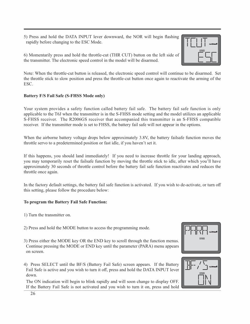
rapidly before changing to the ESC Mode.
6) Momentarily press and hold the throttle-cut (THR CUT) button on the left side of the transmitter. The electronic speed control in the model will be disarmed.
Note: When the throttle-cut button is released, the electronic speed control will continue to be disarmed. Set the throttle stick to slow position and press the throttle-cut button once again to reactivate the arming of the ESC.
Battery F/S Fail Safe (S-FHSS Mode only)
Your system provides a safety function called battery fail safe. The battery fail safe function is only applicable to the T6J when the transmitter is in the S-FHSS mode setting and the model utilizes an applicable S-FHSS receiver. The R2006GS receiver that accompanied this transmitter is an S-FHSS compatible receiver. If the transmitter mode is set to FHSS, the battery fail safe will not appear in the options.
When the airborne battery voltage drops below approximately 3.8V, the battery failsafe function moves the
approximately 30 seconds of throttle control before the battery fail safe function reactivates and reduces the throttle once again.
this setting, please follow the procedure below:
To program the Battery Fail Safe Function:
1) Turn the transmitter on.
2) Press and hold the MODE button to access the programming mode.
3) Press either the MODE key OR the END key to scroll through the function menus. Continue pressing the MODE or END key until the parameter (PARA) menu appears on screen.
4) Press SELECT until the BF/S (Battery Fail Safe) screen appears. If the Battery
down.
The ON indication will begin to blink rapidly and will soon change to display OFF. If the Battery Fail Safe is not activated and you wish to turn it on, press and hold
27
the DATA INPUT lever upward. The OFF indication will begin to blink rapidly and will soon change to display ON.
5) Press and hold the END button to exit the programming menu.
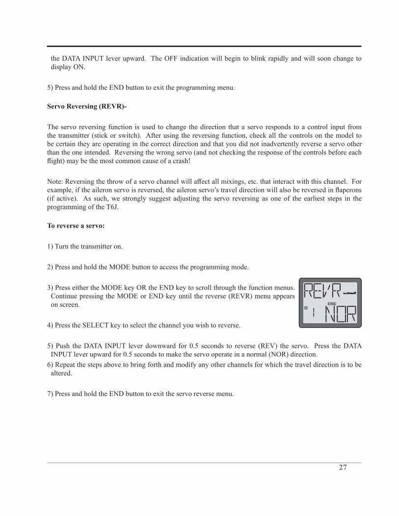
Servo Reversing (REVR)-
The servo reversing function is used to change the direction that a servo responds to a control input from the transmitter (stick or switch). After using the reversing function, check all the controls on the model to be certain they are operating in the correct direction and that you did not inadvertently reverse a servo other than the one intended. Reversing the wrong servo (and not checking the response of the controls before each
(if active). As such, we strongly suggest adjusting the servo reversing as one of the earliest steps in the programming of the T6J.
To reverse a servo:
1) Turn the transmitter on.
2) Press and hold the MODE button to access the programming mode.
3) Press either the MODE key OR the END key to scroll through the function menus. Continue pressing the MODE or END key until the reverse (REVR) menu appears on screen.
4) Press the SELECT key to select the channel you wish to reverse.
5) Push the DATA INPUT lever downward for 0.5 seconds to reverse (REV) the servo. Press the DATA INPUT lever upward for 0.5 seconds to make the servo operate in a normal (NOR) direction.
6) Repeat the steps above to bring forth and modify any other channels for which the travel direction is to be altered.
7) Press and hold the END button to exit the servo reverse menu.

28
Dual Rates/Exponential Settings-
Dual Rates/Exponential Settings vary slightly between the airplane (ACRO) mode and the helicopter (HELI) mode. As such, the information pertaining to these functions will be separated into ACRO and HELI sections below. Please adhere to the section that pertains to the model for which you are programming the T6J transmitter.
ACRO Dual Rates/Exponential Information:
Dual Rates (ACRO):
reduce the travel amount of the channel respectively.
For example, if the elevator of the aircraft travels 1/2” at the high rate and maximum stick input, and a value of 50% is input for the low rate, when the switch is moved to the low rate position, the servo moves exactly half as far per stick position. Following this example, if the elevator control input is all the way up, the maximum travel is now 1/4”
The T6J transmitter offers dual rates on the aileron, elevator and rudder channels. The dual rates are assignable to any of the switches on the transmitter and all are simultaneously activated by the dual rate switch selected.
The amount of travel decrease for each control may be set between 0% and 140% of the values set for the end points (explained in End Point Adjustment on page 33).
Note: It is possible to set a dual rate value to zero, thus causing no response from that channel when the dual rates are activated. If the dual rates are inadvertently set to zero, a crash could result.
Note:
D/R Dual Rate Settings (ACRO)
To select the Switch/position to control the dual rates:
Prior to programming the dual rates for the aileron, elevator or rudder channels, we suggest selection of the switch that will be utilized to control the rate settings.
1) Turn the transmitter on.
2) Press and hold the MODE button to access the programming mode.
3) Press either the MODE key OR the END key to scroll through the function menus. Each time one of the aforementioned keys is pressed the menu will change accordingly. Continue pressing the MODE or END
29
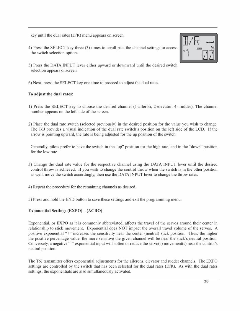
key until the dual rates (D/R) menu appears on screen.
4) Press the SELECT key three (3) times to scroll past the channel settings to access the switch selection options.
5) Press the DATA INPUT lever either upward or downward until the desired switch selection appears onscreen.
6) Next, press the SELECT key one time to proceed to adjust the dual rates.
To adjust the dual rates:
1) Press the SELECT key to choose the desired channel (1-aileron, 2-elevator, 4- rudder). The channel number appears on the left side of the screen.
2) Place the dual rate switch (selected previously) in the desired position for the value you wish to change.
arrow is pointing upward, the rate is being adjusted for the up position of the switch.
for the low rate.
3) Change the dual rate value for the respective channel using the DATA INPUT lever until the desired control throw is achieved. If you wish to change the control throw when the switch is in the other position as well, move the switch accordingly, then use the DATA INPUT lever to change the throw rates.
4) Repeat the procedure for the remaining channels as desired.
5) Press and hold the END button to save these settings and exit the programming menu.
Exponential Settings (EXPO) – (ACRO)
relationship to stick movement. Exponential does NOT impact the overall travel volume of the servos. A
neutral position.
settings are controlled by the switch that has been selected for the dual rates (D/R). As with the dual rates settings, the exponentials are also simultaneously activated.

30
the end points (explained in End Point Adjustment on page 33).
To set the exponentials:
1) Turn the transmitter on.
2) Press and hold the MODE button to access the programming mode.
3) Press either the MODE key OR the END key to scroll through the function menus. Continue pressing the MODE or END key until the exponentials (EXPO) menu appears on screen.
4) Press the SELECT key to choose the desired channel (1-aileron, 2-elevator, 4- rudder) and switch position. The channel number appears on the left side of the screen. The switch position (up or down) is indicated by the arrow above or below the channel indicator. The channel number appears on the left side of the screen.
5) Place the dual rate switch, selected previously, (which also serves as the exponential switch) in the desired
position on the left side of the LCD. If the arrow is pointing upward, the exponential is being adjusted for the up position of the switch.
6) Change the exponential rate value for the respective channel using the DATA INPUT lever until the
7) Place the dual rate/exponential switch in the opposite position, adjust the rates accordingly.
8) Repeat the procedure for the remaining channels as desired.
9) Press and hold the END button to save these settings and exit the programming menu.
HELI Dual Rates/Exponential Information:
Dual Rates (HELI):
reduce the travel amount of the channel respectively.
For example, if the rudder of the helicopter travels 1/2” at the high rate and maximum stick input, and a value of 50% is input for the low rate, when the switch is moved to the low rate position, the servo moves exactly
maximum travel is now 1/4”
31
The T6J transmitter offers dual rates on the aileron, elevator and rudder channels. The dual rates are assignable to switches A, B or IDL on the transmitter and are simultaneously activated by the dual rate switch selected.
The amount of travel decrease for each control may be set between 0% and 140% of the values set for the end points (explained in End Point Adjustment on page 33).
Note: It is possible to set a dual rate value to zero, thus causing no response from that channel when the dual rates are activated. If the dual rates are inadvertently set to zero, a crash could result.
Note:
Dual Rate Settings (HELI)
To select the Switch/position to control the dual rates:
Prior to programming the dual rates for the aileron, elevator or rudder channels, we suggest selection of the switch that will be utilized to control the rate settings.
1) Turn the transmitter on.
2) Press and hold the MODE button to access the programming mode. An audible double beep will be heard and the default screen will change accordingly.
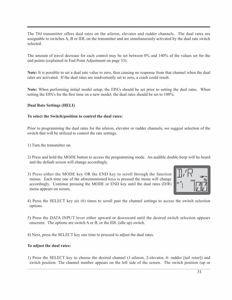
3) Press either the MODE key OR the END key to scroll through the function menus. Each time one of the aforementioned keys is pressed the menu will change accordingly. Continue pressing the MODE or END key until the dual rates (D/R) menu appears on screen.
4) Press the SELECT key six (6) times to scroll past the channel settings to access the switch selection options.
5) Press the DATA INPUT lever either upward or downward until the desired switch selection appears onscreen. The options are switch A or B, or the IDL (idle up) switch.
4) Next, press the SELECT key one time to proceed to adjust the dual rates.
To adjust the dual rates:
1) Press the SELECT key to choose the desired channel (1-aileron, 2-elevator, 4- rudder [tail rotor]) and switch position. The channel number appears on the left side of the screen. The switch position (up or

32
2) Observing the up/down switch position indicator, change the dual rate value for the respective channel using the DATA INPUT lever until the desired control throw is achieved.
Again, if the arrow is pointing upward, the rate is being adjusted for the up position of the switch.
for the low rate.
3) Press the SELECT key to change the switch position indicator to the opposite position.
Note: This assumes that the modeler has adjusted the up switch position. If the down switch position was adjusted, the SELECT key will move to the next channel or switch selection menu as the case may be.
4) Change the dual rate value for the respective channel using the DATA INPUT lever until the desired control throw is achieved.
5) Repeat the procedure for the remaining channels and switch positions as desired.
6) Press and hold the END button to save these settings and exit the programming menu.
Exponential Settings (EXPO) - HELI
relationship to stick movement. Exponential does NOT impact the overall travel volume of the servos. A
neutral position.
settings are controlled by the switch that has been selected for the dual rates (D/R). As with the dual rates settings, the exponentials are also simultaneously activated.
the end points (explained in End Point Adjustment on page 33).
To set the exponentials:
1) Turn the transmitter on.

33
2) Press and hold the MODE button to access the programming mode.
3) Press either the MODE key OR the END key to scroll through the function menus. Continue pressing the MODE or END key until the exponentials (EXPO) menu appears on screen.
4) Press the SELECT key to choose the desired channel (1-aileron, 2-elevator, 4- rudder [tail rotor]) and switch position. The channel number appears on the left side of the screen. The switch position (up or down) is indicated by the arrow above or below the channel indicator. The channel number appears on the left side of the screen.
5) Observing the up/down switch position indicator, change the exponential value for the respective channel using the DATA INPUT lever until the desired sensitivity of the respective gimbal stick near center is achieved.
Again, if the arrow is pointing upward, the rate is being adjusted for the up position of the switch. Generally,
rate.
6) Change the exponential rate value for the respective channel using the DATA INPUT lever until the
7 Press the SELECT key to change the switch position indicator to the opposite position.
Note: This assumes that the modeler has adjusted the up switch position. If the down switch position was adjusted, the SELECT key will move to the next channel or switch selection menu as the case may be.
8) Change the dual rate value for the respective channel using the DATA INPUT lever until the desired control throw is achieved.
9) Repeat the procedure for the remaining channels and switch positions as desired.
10) Press and hold the END button to save these settings and exit the programming menu.
End Point Adjustment (EPA)-
connected to the servo arms and control horns so that the correct, or near correct control surface throw will
below 70% or above 120% to get the desired throw, you should strongly consider changing the pushrod
34
connections so the values can be set closer to 100%. When the EPA is set to 100%, the maximum servo throw for channels 1, 2, 3, and 4 is approximately 400 and approximately 550 for channels 5 and 6.
Note:
throws will also change. Additionally, it is possible for the dual rates, mixings, etc. to also overthrow (or overdrive) the end point adjustments. It is important to test these functions to ensure that binding does not occur.
To set the end points:
1) Turn the transmitter on.
2) Press and hold the MODE button to access the programming mode.
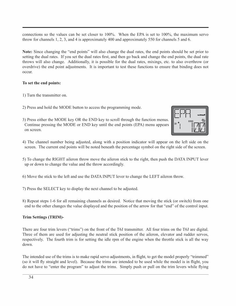
3) Press either the MODE key OR the END key to scroll through the function menus. Continue pressing the MODE or END key until the end points (EPA) menu appears on screen.
4) The channel number being adjusted, along with a position indicator will appear on the left side on the screen. The current end points will be noted beneath the percentage symbol on the right side of the screen.
5) To change the RIGHT aileron throw move the aileron stick to the right, then push the DATA INPUT lever up or down to change the value and the throw accordingly.
6) Move the stick to the left and use the DATA INPUT lever to change the LEFT aileron throw.
7) Press the SELECT key to display the next channel to be adjusted.
8) Repeat steps 1-6 for all remaining channels as desired. Notice that moving the stick (or switch) from one
Trim Settings (TRIM)-
Three of them are used for adjusting the neutral stick position of the aileron, elevator and rudder servos, respectively. The fourth trim is for setting the idle rpm of the engine when the throttle stick is all the way down.
35
and the neutral position of the servos will shift. Keep in mind that you should start out with the control
adjust the trims once airborne.
Each of the trim levers features an audible tone, or beep, that alerts you when the trim is activated. Additionally, there is a double-beep and a slight pause that occurs when the trim lever is centered (zeroed).
adjustments are required, land the model and then enter the program as described below to adjust the trims in
Note:
however, it is not necessary to start from the beginning.
Center the servos:
1) Turn on the transmitter and receiver. Operate the controls to make sure the servos respond in the correct direction. Use the reversing function to reverse any servos necessary.
2) Center the throttle control stick.
3) Place the servo arms on the servos so they are perpendicular to the pushrods (see page 9). It is okay to cut
4) Connect the pushrods to the control surfaces. Adjust the length of the pushrods until the control surfaces are centered when the servos are centered.
Once the servos and control surfaces have been connected and the control throws have been set using the end
and level.
2) Press and hold the MODE button to access the programming mode.
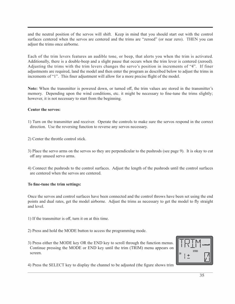
3) Press either the MODE key OR the END key to scroll through the function menus. Continue pressing the MODE or END key until the trim (TRIM) menu appears on screen.

36
adjustments for CH1).
but if the DATA INPUT lever is held long enough the values will change more rapidly.
6) Press the SELECT key to bring forth the trim values for the remaining channels. To change the values for these channels, repeat step 3 above for each channel that requires trim adjustments.
7) Press and hold the END button to exit the programming mode.
Note:
To view the trim settings:
view the trim setting adjustments.
1) Turn the transmitter on. If the transmitter is already on, ensure that it is in the default display mode.
2) With the home page displayed, press and hold the END key. The T6J will then scroll through the trim settings for each of the respective channels. The channel is indicated on the left side of the screen; whereas the trim input will be located on the right side of the LCD.
Sub-Trims (STRM)-
perfect mechanical linkages. The T6J transmitter allows for sub-trim adjustments on all six channels. Rather
Ensure that the linkages are as perfect as possible prior to adjusting the sub-trims. Extremely high sub-trim
To adjust the Sub-Trim settings:
1) Turn the transmitter on.
2) Press and hold the MODE button to access the programming mode.
3) Press either the MODE key OR the END key to scroll through the function menus. Each time one of the aforementioned keys is pressed the menu will change accordingly. Continue pressing the MODE or END
37
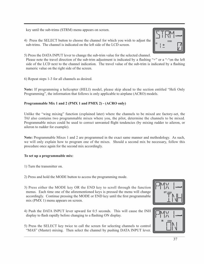
key until the sub-trims (STRM) menu appears on screen.
4) Press the SELECT button to choose the channel for which you wish to adjust the sub-trims. The channel is indicated on the left side of the LCD screen.
5) Press the DATA INPUT lever to change the sub-trim value for the selected channel.
numeric value on the right side of the screen.
6) Repeat steps 1-3 for all channels as desired.
Note:Programming”, the information that follows is only applicable to airplane (ACRO) models.
Programmable Mix 1 and 2 (PMX 1 and PMIX 2) - (ACRO only)
T6J also contains two programmable mixes where you, the pilot, determine the channels to be mixed.
aileron to rudder for example).
Note: Programmable Mixes 1 and 2 are programmed in the exact same manner and methodology. As such, we will only explain how to program one of the mixes. Should a second mix be necessary, follow this procedure once again for the second mix accordingly.
To set up a programmable mix:
1) Turn the transmitter on.
2) Press and hold the MODE button to access the programming mode.
3) Press either the MODE key OR the END key to scroll through the function menus. Each time one of the aforementioned keys is pressed the menu will change
mix (PMX 1) menu appears on screen.
4) Push the DATA INPUT lever upward for 0.5 seconds. This will cause the INH
5) Press the SELECT key twice to call the screen for selecting channels to control
38
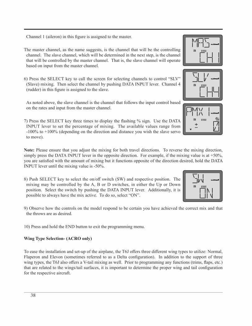
The master channel, as the name suggests, is the channel that will be the controlling channel. The slave channel, which will be determined in the next step, is the channel that will be controlled by the master channel. That is, the slave channel will operate based on input from the master channel.
(Slave) mixing. Then select the channel by pushing DATA INPUT lever. Channel 4
As noted above, the slave channel is the channel that follows the input control based on the rates and input from the master channel.
INPUT lever to set the percentage of mixing. The available values range from
to move).
Note: Please ensure that you adjust the mixing for both travel directions. To reverse the mixing direction,
INPUT lever until the mixing value is -50%.
mixing may be controlled by the A, B or D switches, in either the Up or Down position. Select the switch by pushing the DATA INPUT lever. Additionally, it is
9) Observe how the controls on the model respond to be certain you have achieved the correct mix and that the throws are as desired.
10) Press and hold the END button to exit the programming menu.
Wing Type Selection- (ACRO only)
for the respective aircraft.

39
Normal-
The T6J transmitter defaults to the normal wing type (non-selectable). If your model uses a single servo to control the ailerons, there is nothing more to do. If, however, you are using separate servos to control each aileron individually, please activate the Flaperon mixing. Information on how to do so is contained in the section that follows.
Flaperon mixing (FLPR)- (ACRO only)
The ability to use separate servos to function in the same
function allows the ailerons to be used both as ailerons and as
Flap control is assigned to Channel 6, the proportional rotary knob on the front of the transmitter. As such,
course, by the aileron stick accordingly.
Note: A trim input on the aileron channel will move the two wing servos in the opposite direction. If so desired, sub-trim must be input for the two wing servos individually as it impacts the servos rather than their function.
1) Turn the transmitter on.
2) Press and hold the MODE button to access the programming mode.
3) Press either the MODE key OR the END key to scroll through the function menus. Continue pressing the MODE or END key until the flaperon (FLPR) wing menu appears on screen.
4) Push the DATA INPUT lever upward for approximately two (2) seconds. This will
Note:
5) Connect the aileron servo in the right wing to channel 1 (aileron) in the receiver and connect the aileron
*If necessary, use the Servo Reversing function to achieve the correct direction of servo throws.

40
toward the downward from the aileron surface.
travel (reducing the amount of downward aileron travel) to create a more axial roll rate; reducing unwanted yaw of the aircraft.
7) Once the mix has been activated, move the servos to their full extremes to make certain they are not overdriving the controls. If necessary, adjust the linkages to achieve the correct control throws.
8) Press and hold the END key to exit the programming menu.
1) Turn the transmitter on.
2) Press and hold the MODE button to access the programming mode.
3) Press either the MODE key OR the END key to scroll through the function menus. Continue pressing the MODE or END key until the flaperon (FLPR) wing menu appears on screen.
4) Push the DATA INPUT lever upward for approximately two (2) seconds. This will
5) Connect the aileron servo in the right wing to channel 1 (aileron) in the receiver and connect the aileron servo in the left wing to an unused channel from 3-6, depending upon the model aircraft.
Note: When using a channel other than channel 6, other programming options and functionality will be affected accordingly. For example, channel 3 is used as the throttle control in Futaba transmitters. If channel 3 is selected as the left aileron channel, it will not be operational from the throttle stick, only the aileron.

41
surface.
7) Once the mix has been activated, move the servos to their full extremes to make certain they are not overdriving the controls. If necessary, adjust the linkages to achieve the correct control throws.
8) Press and hold the END key to exit the programming menu.
Flap trim (FLTR)- (ACRO only)
1) Turn the transmitter on.
2) Press and hold the MODE button to access the programming mode.
3) Press either the MODE key OR the END key to scroll through the function menus.
on screen.
4) Push the DATA INPUT lever upward for approximately two (2) seconds. This will
the DATA INPUT lever upward or downward.
Note: When using switches A, B or D, it is possible to incorporate two rates- upward or downward.
Note:
and channel 6.

42
5) Press the DATA INPUT lever either upward or downward until the desired switch selection appears onscreen. In addition to switches A, B and D, it is also possible to use the rotary knob (VR) to control the
6) Press and hold the END button to exit the programming menu.
V-tail mixing (V-TL)- (ACRO only)
Intended for V-tail aircraft (such as a Beechcraft Bonanza), V-tail mixing allows the ruddervators to operate both as rudders and elevators. The servos work together as an elevator; yet will also work in opposition to one another to function as a rudder.
The same as the other mixes, V-tail mixing requires that each ruddervator be operated by a separate servo.
mixing simultaneously.
To activate V-tail mixing:
1) Connect the left ruddervator servo to channel 2 (elevator) in the receiver and connect the right ruddervator servo to channel 4 (rudder) in the receiver.
2) Turn the transmitter on.
3) Press and hold the MODE button to access the programming mode.
4) Press either the MODE key OR the END key to scroll through the function menus. Continue pressing the MODE or END key until the V-tail (V-TL) menu appears on screen.
5) Push the DATA INPUT lever upward for approximately two (2) seconds. This will
DATA INPUT lever to set the percentage of elevator travel rates. The available
*If necessary, use the Servo Reversing function to achieve the correct direction of servo throws.

43
percentage of rudder travel rates. The available adjustments are between -100% and
8) Once this mix has been activated, move the servos to their full extremes to make certain they are not overdriving the controls. If necessary, adjust the linkages to achieve the correct control throws.
Note: It is important to ensure that no binding occurs when providing full elevator and full rudder inputs. This will maximize the inputs from both channels and provide you with the worst-case scenario.
9) Press and hold the END button to exit the programming menu.
Elevon mixing (ELVN)- (ACRO only)
and flying wings, elevon mixing mixes channel 1 (aileron) to channel 2 (elevator) allowing the elevons to operate in unison (as elevators) or in opposition (as ailerons). This function requires that each elevon be operated by a separate servo.
Note: The Elevon function can not be utilized when either the
activated, it will not be possible to activate the elevon mixing function.
To activate elevon mixing:
1) Connect the servo in the right wing channel to channel 2 (elevator) in the receiver and connect the servo in the left wing to channel 1 (aileron) in the receiver.
2) Turn the transmitter on.
3) Press and hold the MODE button to access the programming mode.
4) Press either the MODE key OR the END key to scroll through the function menus. Continue pressing the MODE or END key until the elevon (ELVN) menu appears on screen.
CH1 CH2
*If necessary, use the Servo Reversing function to achieve the correct direction of servo throws.

44
Use the DATA INPUT lever to set the percentage of rudder travel rate. The values are adjustable from
8) Once this mix has been activated, move the servos to their full extremes to make certain they are not overdriving the controls. If necessary, adjust the linkages to achieve the correct control throws.
Note: It is important to ensure that no binding occurs when providing full elevator and full aileron inputs. This will maximize the inputs from both channels and provide you with the worst-case scenario.
9) Press and hold the END button to exit the programming menu.
Throttle Curve (T-CV)- (ACRO only)
The throttle curve (T-CV) function is designed to optimize the engine, or throttle response, in relation to the
the throttle movement.
assign the throttle curve to any of the switches on the transmitter.
Generally speaking, the points should be adjusted as follows:
• Point 1 is the throttle stick all the way downward (slow) position. • Point 2 is the throttle stick approximately ¼ of the way advanced. • Point 3 is the throttle stick approximately ½ of the way advanced. • Point 4 is the throttle stick approximately 3/4 of the way advanced. • Point 5 is throttle stick all the way upward (hi) position.
To select the throttle curve activation switch:
1) Turn the transmitter on.
2) Press and hold the MODE button to access the programming mode.
45
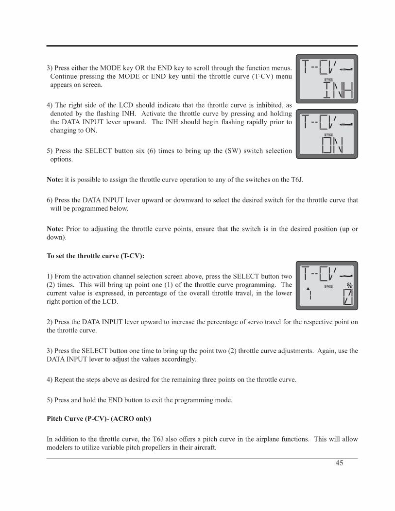
3) Press either the MODE key OR the END key to scroll through the function menus. Continue pressing the MODE or END key until the throttle curve (T-CV) menu appears on screen.
4) The right side of the LCD should indicate that the throttle curve is inhibited, as
changing to ON.
5) Press the SELECT button six (6) times to bring up the (SW) switch selection options.
Note: it is possible to assign the throttle curve operation to any of the switches on the T6J.
6) Press the DATA INPUT lever upward or downward to select the desired switch for the throttle curve that will be programmed below.
Note: Prior to adjusting the throttle curve points, ensure that the switch is in the desired position (up or down).
To set the throttle curve (T-CV):
1) From the activation channel selection screen above, press the SELECT button two (2) times. This will bring up point one (1) of the throttle curve programming. The current value is expressed, in percentage of the overall throttle travel, in the lower right portion of the LCD.
2) Press the DATA INPUT lever upward to increase the percentage of servo travel for the respective point on the throttle curve.
3) Press the SELECT button one time to bring up the point two (2) throttle curve adjustments. Again, use the DATA INPUT lever to adjust the values accordingly.
4) Repeat the steps above as desired for the remaining three points on the throttle curve.
5) Press and hold the END button to exit the programming mode.
Pitch Curve (P-CV)- (ACRO only)
modelers to utilize variable pitch propellers in their aircraft.

46
The switch that controls the throttle curve, as described previously, will also control the pitch curve as well.
a switch.
“Normal” Mode:
Idle-Up” Mode: Allows you to reverse the thrust of the propeller. When you have your throttle stick in the center position (0% throttle) you will not have any pitch. As you push the stick forward (100% throttle) you get positive pitch which allows the airplane to move forward. When you pull the throttle stick back (–100% throttle) it applies negative pitch to the blades and allows the plane to go in reverse.
For information on the proper pitch and throttle curves, please refer to the instructions that accompanied the variable pitch equipment.
To set the pitch curve (P-CV):
1) Turn the transmitter on.
2) Press and hold the MODE button to access the programming mode.
3) Press either the MODE key OR the END key to scroll through the function menus. Continue pressing the MODE or END key until the pitch curve (P-CV) menu appears on screen.
4) The right side of the LCD should indicate that the pitch curve is inhibited, as denoted by the flashing INH. Activate the pitch curve by pressing and holding
changing to ON.
Note: It is imperative to activate the throttle curve before programming the pitch curve. If the throttle curve has not been activated, the pitch curve will not be accessible.
5) Press the SELECT button two (2) times. This will bring up point one (1) of the pitch curve programming. The current value is expressed, in percentage of the overall throttle travel, in the lower right portion of the LCD.
6) Press the DATA INPUT lever upward to increase the percentage of servo travel for the respective point on the pitch curve.

47
7) Press the SELECT button one time to bring up the point two (2) pitch curve adjustments. Again, use the DATA INPUT lever to adjust the values accordingly.
8) Repeat the steps above as desired for the remaining three points on the pitch curve.
9) Move the assigned throttle/pitch curve switch to the opposite position and program the desired points accordingly.
10) Press and hold the END button to exit the programming mode.
Helicopter Only Programming:
The information which follows is only applicable to helicopter (HELI) models. If you are programming an airplane (ACRO) model, please skip ahead to the Fail Safe information which is applicable to both airplane and helicopter model memories.
Normal throttle curve function (N-TH)- (HELI only)-
The throttle curve (T-CV) function is designed to optimize the engine, or throttle response, in relation to the
the throttle movement.
A 5-point throttle curve is utilized to best match the blade collective pitch to the engine RPM for consistent load on the engine. Throttle curve can be adjusted from 0-100% each point. This normal throttle curve creates a basic curve for hovering. Use this function together with the normal pitch curve (see Normal pitch curve) so that the engine RPM remains fairly constant regardless of pitch changes.
While each helicopter manufacturer will have specific recommendations for your flying style, generally speaking, the points should be adjusted as follows:
• Point 1 is shown initially which is throttle stick all the way downward (slow) position. • Point 2 is the throttle stick approximately ¼ of the way advanced. • Point 3 is the throttle stick approximately ½ of the way advanced. • Point 4 is the throttle stick approximately 3/4 of the way advanced. • Point 5 is throttle stick all the way upward (hi) position.
To set the normal throttle curve:
1) Turn the transmitter on.
2) Press and hold the MODE button to access the programming mode.

48
3) Press either the MODE key OR the END key to scroll through the function menus. Continue pressing the MODE or END key until the normal throttle curve (N-TH) menu appears on screen.
4) The LCD screen will contain the throttle curve point indication (left side of screen), as well as the current throttle curve value, expressed as a percentage of travel, on the right side of the display.
Note: Point 1 is shown initially which is throttle stick all the way downward (slow) position. Point 5 is throttle stick all the way upward (hi) position.
Press the DATA INPUT lever upward to increase the percentage of servo travel for the respective point on the throttle curve. Press the DATA INPUT lever downward to decrease the percentage of servo travel for the respective point on the throttle curve.
5) Press the SELECT button one time to bring up the point two (2) throttle curve adjustments. Again, use the DATA INPUT lever to adjust the values accordingly.
6) Repeat the previous steps to set the normal throttle curve point values for the remaining three (3) points.
7) Press and hold the END button to exit the programming mode.
Normal pitch curve (N-PI)-(HELI only)-
This curve is utilized to best match the blade collective pitch to the engine RPM for consistent load on the engine. Pitch curve can be adjusted from 0-100% each point. This normal pitch curve creates a basic curve for hovering. Use this function together with the normal throttle curve to obtain the performance you desire.
While each helicopter manufacturer will have specific recommendations for your flying style, generally speaking, the points should be adjusted as follows:
• Point 1- the collective servo is at the desired lowest point with the throttle stick at the lowest (bottom) position. • Point 2- the collective servo is at the desired point with the throttle stick is advanced ¼ of the way. • Point 3- the collective servo is at the desired point with the throttle stick advanced ½ way. • Point 4- the collective servo is at the desired point with the throttle stick advanced ¾ of the way. • Point 5- the collective servo is at the desired point with the throttle servo fully advanced.

49
To set the normal pitch curve:
1) Turn the transmitter on.
2) Press and hold the MODE button to access the programming mode.
3) Press either the MODE key OR the END key to scroll through the function menus. Continue pressing the MODE or END key until the normal pitch curve (N-PI) menu appears on screen.
4) The LCD screen will contain the pitch curve point indication (left side of screen), as well as the current pitch curve value, expressed as a percentage of travel, on the right side of the display.
Note: Point 1 is shown initially which is throttle stick all the way downward (slow) position. Point 5 is throttle stick all the way upward (hi) position.
Press the DATA INPUT lever upward to increase the percentage of servo travel for the respective point on the pitch curve. Press the DATA INPUT lever downward to decrease the percentage of servo travel for the respective point on the pitch curve.
5) Press the SELECT button one time to bring up the point two (2) pitch curve adjustments. Again, use the DATA INPUT lever to adjust the values accordingly.
6) Repeat the previous steps to set the normal pitch curve point values for the remaining three (3) points.
7) Press and hold the END button to exit the programming mode.
Idle Up throttle curve function (I-TH)- (HELI Only)-
the input from the throttle stick position. Thus, allowing the throttle operation to be adjusted to meet the
A 5-point throttle curve is utilized to best match the blade collective pitch to the engine RPM for consistent load on the engine. Throttle curve can be adjusted from 0-100% each point. Idle up create a curve typically
even when the stick is pulled all the way back. This is one of the functions that makes maneuvers such as

50
• Point 1 is shown initially which is throttle stick all the way downward (slow) position. • Point 2 is the throttle stick approximately ¼ of the way advanced. • Point 3 is the throttle stick approximately ½ of the way advanced. • Point 4 is the throttle stick approximately 3/4 of the way advanced. • Point 5 is throttle stick all the way upward (hi) position.
To set the idle up throttle curve:
1) Turn the transmitter on.
2) Press and hold the MODE button to access the programming mode. An audible double beep will be heard and the default screen will change accordingly.
3) Press either the MODE key OR the END key to scroll through the function menus. Continue pressing the MODE or END key until the idle up throttle curve (I-TH) menu appears on screen.
although depending upon the position of the idle up switch, it may not be on.
5) Push the SELECT key. The LCD screen will contain the throttle curve point indication (left side of screen), as well as the current throttle curve value, expressed as a percentage of travel, on the right side of the display.
Note: Point 1 is shown initially which is throttle stick all the way downward (slow) position. Point 5 is throttle stick all the way upward (hi) position.
Press the DATA INPUT lever upward to increase the percentage of servo travel for the respective point on the throttle curve. Press the DATA INPUT lever downward to decrease the percentage of servo travel for the respective point on the throttle curve.
6) Press the SELECT button one time to bring up the point two (2) throttle curve adjustments. Again, use the DATA INPUT lever to adjust the values accordingly.
7) Repeat the previous steps to set the idle up throttle curve point values for the remaining three (3) points.
8) Press the DATA INPUT lever either upward or downward to select Switch A, B or C as the idle up activation switch.

51
Note: As with all switch selection availability, if the modeler has programmed any other functionality to this switch selection, the idle up throttle curve and the other function will be activated simultaneously. As such, it is imperative to ensure that these desired functions will not negatively impact one another.
For example, if the modeler has programmed Switch B to activate the low rates, and then selected Switch B as the activation switch for the idle up curves, moving Switch B will activate both functions simultaneously.
Note: if the trainer function is activated, the switch C is allocated for the trainer function automatically.
9) Press and hold the END button to exit the programming mode.
Pitch Curve Idle UP (I-PI) - (HELI only)
A 5-point pitch curve is utilized to best match the blade collective pitch to the engine RPM for consistent load on the engine. The curve can be adjusted from 0-100% each point. Idle up creates a curve typically
even when the stick is pulled all the way back. This is one of the functions that makes the maneuvers such as
• Point 1- the collective servo is at the desired lowest point with the throttle stick at the lowest (bottom) position. This is normally full negative pitch. • Point 2- the collective servo is at the desired point with the throttle stick is advanced ¼ of the way. • Point 3- the collective servo is at the desired point with the throttle stick advanced ½ way. • Point 4- the collective servo is at the desired point with the throttle stick advanced ¾ of the way. • Point 5- the collective servo is at the desired point with the throttle stick fully advanced. This is full positive pitch.
To set the idle up pitch curve:
1) Turn the transmitter on.
2) Press and hold the MODE button to access the programming mode. An audible double beep will be heard and the default screen will change accordingly.
3) Press either the MODE key OR the END key to scroll through the function menus. Continue pressing the MODE or END key until the idle up pitch curve (I-PI) menu

52
appears on screen.
4) The LCD screen will contain the pitch curve point indication (left side of screen), as well as the current pitch curve value, expressed as a percentage of travel, on the right side of the display.
Note: Point 1 is shown initially which is throttle stick all the way downward (slow) position. Point 5 is throttle stick all the way upward (hi) position.
Press the DATA INPUT lever upward to increase the percentage of servo travel for the respective point on the pitch curve. Press the DATA INPUT lever downward to decrease the percentage of servo travel for the respective point on the pitch curve.
5) Press the SELECT button one time to bring up the point two (2) pitch curve adjustments. Again, use the DATA INPUT lever to adjust the values accordingly.
6) Repeat the previous steps to set the normal pitch curve point values for the remaining three (3) points.
7) Press and hold the END button to exit the programming mode.
Throttle hold function (HOLD)- (HELI only)-
Throttle hold function is typically used for autorotations where only pitch control is used to make a descent
Note: The collective servo remains active to allow for pitch inputs during the descent of the helicopter.
To set the throttle hold:
1) Turn the transmitter on.
2) Press and hold the MODE button to access the programming mode. An audible double beep will be heard and the default screen will change accordingly.
3) Press either the MODE key OR the END key to scroll through the function menus. Continue pressing the MODE or END key until the throttle hold (HOLD) menu appears on screen.
INH. Activate the throttle hold by pressing and holding the DATA INPUT lever upward. The INH should

53
5) Push the SELECT key to bring up the throttle hold adjustment screen.
to engage the throttle hold. Press the DATA INPUT lever upward or downward to adjust the throttle hold function accordingly.
7) Press and hold the END button to exit the programming mode.
Pitch Curve Hold (H-PI)- (HELI only)
is activated when the throttle hold switch is enabled. This allows the pilot to have complete control of the blade pitch during a non-powered descent. The pitch curve for throttle hold can be adjusted from 0-100% for
Generally speaking, the pitch curve should be set up so that:
• Point 1- the collective servo is at the desired lowest point with the throttle stick at the lowest (bottom) position. This is also full negative pitch. • Point 2- the collective servo is at the desired point with the throttle stick is advanced ¼ of the way. • Point 3- the collective servo is at the desired point with the throttle stick advanced ½ way. • Point 4- the collective servo is at the desired point with the throttle stick advanced ¾ of the way. • Point 5- the collective servo is at the desired point with the throttle servo fully advanced. This is full positive pitch.
To set the throttle hold pitch curve:
1) Turn the transmitter on.
2) Press and hold the MODE button to access the programming mode. An audible double beep will be heard and the default screen will change accordingly.
3) Press either the MODE key OR the END key to scroll through the function menus. Continue pressing the MODE or END key until the hold pitch curve (H-PI) menu appears on screen.
4) This will bring up point one (1) of the hovering pitch curve programming. The current value is expressed, in percentage of the overall pitch travel, in the lower right portion of the LCD.
5) Press the DATA INPUT lever upward to increase the percentage of the collective servo travel for the respective point on the pitch curve.

54
6) Press the SELECT button to bring up the point two (2) pitch curve adjustments. Again, use the DATA INPUT lever to adjust the values accordingly.
7) Repeat the steps above as desired for the remaining three points on the pitch curve.
8) Press and hold the END button to exit the programming mode.
Revolution Mixing (REVO) - (HELI only)
pitch inputs. This mixing assists in compensating for the rotation of the helicopter caused by the increased torque. The T6J transmitter allows for a high rate and a low rate adjustment for the revolution mixing.
Note: If using a heading hold/AVCS gyro, only use the revolution mixing when this gyro is in the normal mode. Do NOT use revolution mixing with a heading hold/AVCS gyro when it is in the heading-hold/AVCS mode.
1) Turn the transmitter on.
2) Press and hold the MODE button to access the programming mode.
3) Press either the MODE key OR the END key to scroll through the function menus. Continue pressing the MODE or END key until the revolution mixing (REVO) menu appears on screen.
4) The right side of the LCD should indicate that the revolution mixing is inhibited, as denoted by the flashing INH. Activate the revolution mixing by pressing and
prior to changing to ON.
5) Push the SELECT key to bring up the low rate (as indicated by the down arrow on the left side of the LCD screen).
6) To adjust the value, press the DATA INPUT lever either upward or downward until the desired value is achieved.
7) Press the SELECT key once again to access the revo mixing adjustments for the high side. The up arrow on the left side of the screen indicates that it is the high side that will be adjusted.
8) To adjust the value, press the DATA INPUT lever either upward or downward until the desired value is achieved.

55
9) After both values have been adjusted accordingly, press and hold the END button to exit the programming mode.
Gyro mixing function (GYRO)-(HELI only)
What is a gyro? Gyro is short for gyroscope. A gyroscope is an electronic unit that senses rotational
How does it help in helicopter setup? A heading-hold gyro will totally eliminate the need for revolution
a complex curve operating properly.
Gyro sensor types:cutting-edge micro electromechanical system, or MEMS, sensors detect smaller angular deviations that any other technology.
Choosing the right gyro for your skills, your helicopter, and your budget:
Mechanical: Some are still available. They are very challenging to set up and not as reliable as piezo or SMM.
Non-heading hold piezo: these are now inexpensive gyros that are reliable and easy to set up. Some have
Heading hold piezo: Until recently, the cream of the crop. Expensive, and more complex to set up. Adds
Heading hold SMM: 21st century gyro technology. Computer chip technology. Expensive, easier set up,
faster response when using specialized digital servos. Examples: • GY401: Simple set up. Ideal for learning aerobatics through 3D. • GY502: Ideal through class III competition. • GY520: Simple set up. Perfect for entry-level models through 3D competitions. • GY611: Exceptional center. Extremely fast response time. Requires specialized servo. • GY701: Exceptional performance. Combining a governor and gyro in one unit. • CGY750: Flybarless system. Incredible performance that combines 3-axis gyro with governor. Requires an adapter for use with the T6J.
a switch on the transmitter.
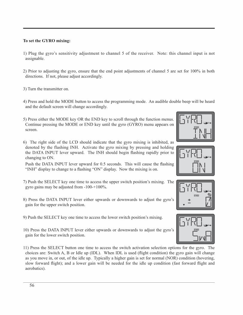
56
To set the GYRO mixing:
assignable.
2) Prior to adjusting the gyro, ensure that the end point adjustments of channel 5 are set for 100% in both directions. If not, please adjust accordingly.
3) Turn the transmitter on.
4) Press and hold the MODE button to access the programming mode. An audible double beep will be heard and the default screen will change accordingly.
5) Press either the MODE key OR the END key to scroll through the function menus. Continue pressing the MODE or END key until the gyro (GYRO) menu appears on screen.
6) The right side of the LCD should indicate that the gyro mixing is inhibited, as denoted by the flashing INH. Activate the gyro mixing by pressing and holding
changing to ON.
gain for the upper switch position.
gain for the lower switch position.
11) Press the SELECT button one time to access the switch activation selection options for the gyro. The
as you move in, or out, of the idle up. Typically a higher gain is set for normal (NOR) condition (hovering,
aerobatics).

57
12) Press and hold the END button to exit the programming mode.
Swash to throttle mixing (SW-T)-(HELI only)
When idle up is activated, this predetermined mixing function is used to prevent the engine from slowing, or
To activate swash to throttle mixing:
1) Turn the transmitter on.
2) Press and hold the MODE button to access the programming mode. An audible double beep will be heard and the default screen will change.
3) Press either the MODE key OR the END key to scroll through the function menus. Continue pressing the MODE or END key until the swashplate to throttle (SW-T) mixing menu appears on screen.
4) Press the SELECT key to display the CH-A. This indicates that the values which will be adjusted are the values of the aileron input.
5) Press the DATA INPUT lever to set the percentage of aileron to throttle mixing rate from 0-100%.
6) Press the SELECT key to display the CH-E. This indicates that the values which will be adjusted are the values of the elevator input.
7) Press the DATA INPUT lever to set the percentage of elevator to throttle mixing rate from 0-100%.
5) Press the SELECT key to display the CH-4. This indicates that the values which will be adjusted are the values of the rudder input.
6) Press the DATA INPUT lever to set the percentage of elevator to throttle mixing rate from -100% to
Swash Ring (RING)-
swash linkages from simultaneous operation of the aileron and elevator inputs. That is, this is basically an electronic version of a former mechanical action that prevented binding of the controls when the elevator/

58
aileron inputs are maximized.
This is very useful for 3D aerobatics. The Ring function is adjustable from 50-200%.
surround the gimbal. For example, show diagram with 50, 100 and 200% values input.
To set the swash ring:
1) Turn the transmitter on.
2) Press and hold the MODE button to access the programming mode. An audible double beep will be heard and the default screen will change accordingly.
3) Press either the MODE key OR the END key to scroll through the function menus. Each time one of the aforementioned keys is pressed the menu will change accordingly. Continue pressing the MODE or END key until the swash ring (RING) menu appears on screen.
4) The right side of the LCD should indicate that the swash ring is inhibited, as denoted by the flashing INH. Activate the swash ring by pressing and holding
changing to ON.
5) Press the SELECT key to call up the default value (50%).
6) To adjust the RING value, press the DATA INPUT lever upward until the desired value is achieved.
Observing your helicopter, ensure that the swash ring function has eliminated any undesired movement or binding when the extreme aileron/elevator inputs are given.
7) Press and hold the END button to exit the programming menu.
Swashplate type selection and Swash AFR (SWSH) - (HELI only)
The Swashplate type selection is utilized to select the swashplate type that matches the respective helicopter
choose from: H-1, HE3, H-3 and HR3.
Prior to explaining the differences in the selections available to you, it is important to have a basic
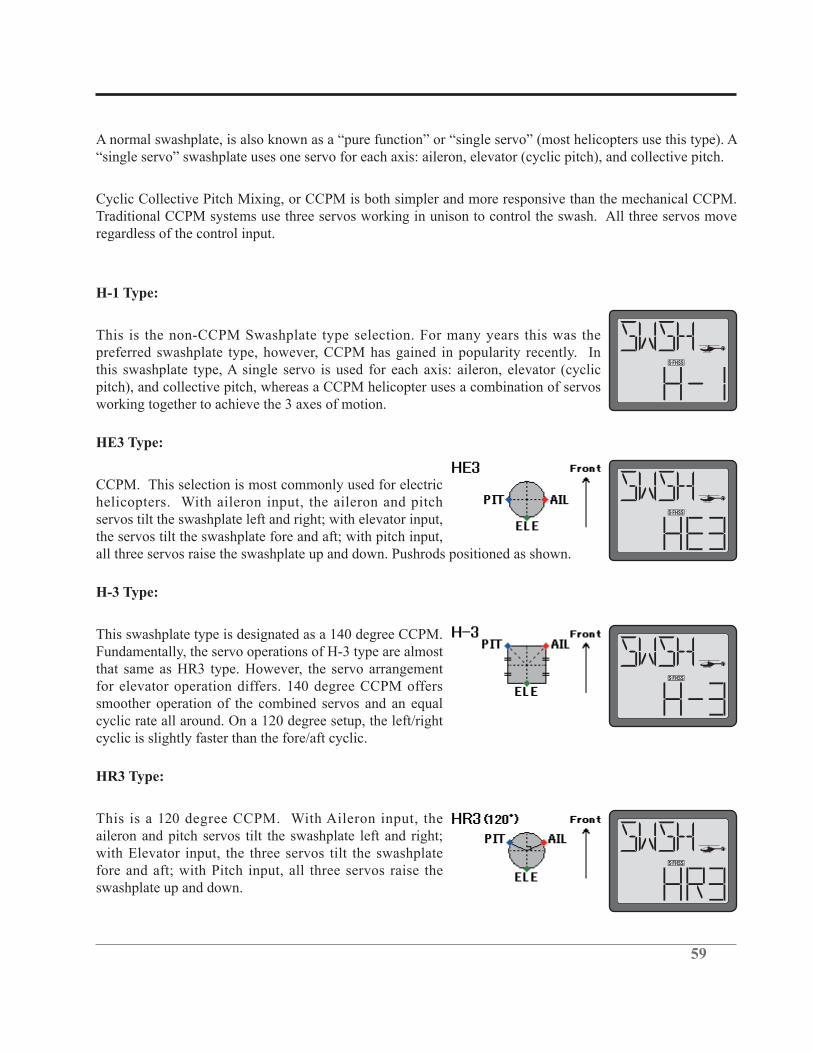
59
Cyclic Collective Pitch Mixing, or CCPM is both simpler and more responsive than the mechanical CCPM. Traditional CCPM systems use three servos working in unison to control the swash. All three servos move regardless of the control input.
H-1 Type:
This is the non-CCPM Swashplate type selection. For many years this was the preferred swashplate type, however, CCPM has gained in popularity recently. In this swashplate type, A single servo is used for each axis: aileron, elevator (cyclic pitch), and collective pitch, whereas a CCPM helicopter uses a combination of servos working together to achieve the 3 axes of motion.
HE3 Type:
CCPM. This selection is most commonly used for electric helicopters. With aileron input, the aileron and pitch servos tilt the swashplate left and right; with elevator input, the servos tilt the swashplate fore and aft; with pitch input, all three servos raise the swashplate up and down. Pushrods positioned as shown.
H-3 Type:
This swashplate type is designated as a 140 degree CCPM. Fundamentally, the servo operations of H-3 type are almost that same as HR3 type. However, the servo arrangement for elevator operation differs. 140 degree CCPM offers smoother operation of the combined servos and an equal cyclic rate all around. On a 120 degree setup, the left/right cyclic is slightly faster than the fore/aft cyclic.
HR3 Type:
This is a 120 degree CCPM. With Aileron input, the aileron and pitch servos tilt the swashplate left and right; with Elevator input, the three servos tilt the swashplate fore and aft; with Pitch input, all three servos raise the swashplate up and down.
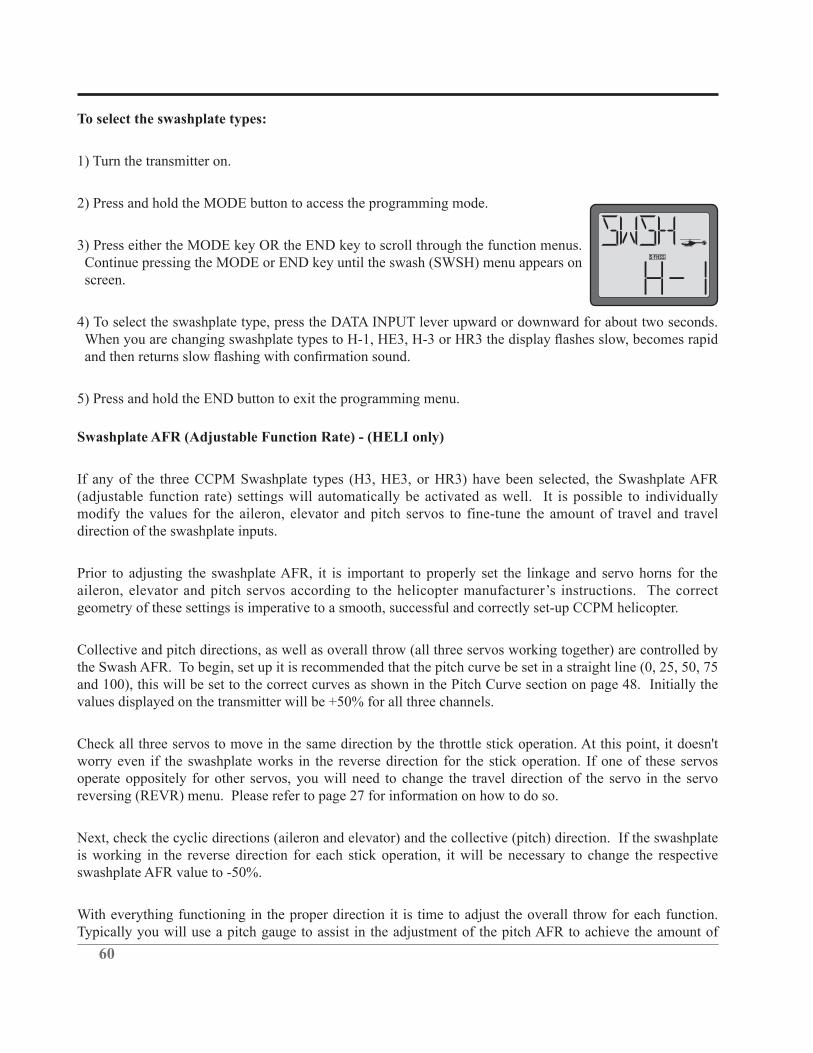
60
To select the swashplate types:
1) Turn the transmitter on.
2) Press and hold the MODE button to access the programming mode.
3) Press either the MODE key OR the END key to scroll through the function menus. Continue pressing the MODE or END key until the swash (SWSH) menu appears on screen.
4) To select the swashplate type, press the DATA INPUT lever upward or downward for about two seconds.
5) Press and hold the END button to exit the programming menu.
Swashplate AFR (Adjustable Function Rate) - (HELI only)
If any of the three CCPM Swashplate types (H3, HE3, or HR3) have been selected, the Swashplate AFR (adjustable function rate) settings will automatically be activated as well. It is possible to individually modify the values for the aileron, elevator and pitch servos to fine-tune the amount of travel and travel direction of the swashplate inputs.
Prior to adjusting the swashplate AFR, it is important to properly set the linkage and servo horns for the
geometry of these settings is imperative to a smooth, successful and correctly set-up CCPM helicopter.
Collective and pitch directions, as well as overall throw (all three servos working together) are controlled by the Swash AFR. To begin, set up it is recommended that the pitch curve be set in a straight line (0, 25, 50, 75 and 100), this will be set to the correct curves as shown in the Pitch Curve section on page 48. Initially the
Check all three servos to move in the same direction by the throttle stick operation. At this point, it doesn't worry even if the swashplate works in the reverse direction for the stick operation. If one of these servos operate oppositely for other servos, you will need to change the travel direction of the servo in the servo reversing (REVR) menu. Please refer to page 27 for information on how to do so.
Next, check the cyclic directions (aileron and elevator) and the collective (pitch) direction. If the swashplate is working in the reverse direction for each stick operation, it will be necessary to change the respective swashplate AFR value to -50%.
With everything functioning in the proper direction it is time to adjust the overall throw for each function. Typically you will use a pitch gauge to assist in the adjustment of the pitch AFR to achieve the amount of
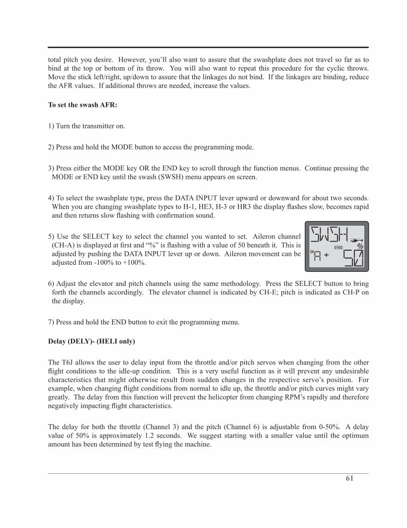
61
bind at the top or bottom of its throw. You will also want to repeat this procedure for the cyclic throws. Move the stick left/right, up/down to assure that the linkages do not bind. If the linkages are binding, reduce the AFR values. If additional throws are needed, increase the values.
To set the swash AFR:
1) Turn the transmitter on.
2) Press and hold the MODE button to access the programming mode.
3) Press either the MODE key OR the END key to scroll through the function menus. Continue pressing the MODE or END key until the swash (SWSH) menu appears on screen.
4) To select the swashplate type, press the DATA INPUT lever upward or downward for about two seconds.
5) Use the SELECT key to select the channel you wanted to set. Aileron channel
adjusted by pushing the DATA INPUT lever up or down. Aileron movement can be
6) Adjust the elevator and pitch channels using the same methodology. Press the SELECT button to bring forth the channels accordingly. The elevator channel is indicated by CH-E; pitch is indicated as CH-P on the display.
7) Press and hold the END button to exit the programming menu.
Delay (DELY)- (HELI only)
The T6J allows the user to delay input from the throttle and/or pitch servos when changing from the other
The delay for both the throttle (Channel 3) and the pitch (Channel 6) is adjustable from 0-50%. A delay value of 50% is approximately 1.2 seconds. We suggest starting with a smaller value until the optimum

62
To program the DELY (Throttle and Pitch Delays):
1) Turn the transmitter on.
2) Press and hold the MODE button to access the programming mode. An audible double beep will be heard and the default screen will change.
3) Press either the MODE key OR the END key to scroll through the function menus. Each time one of the aforementioned keys is pressed the menu will change accordingly. Continue pressing the MODE or END key until the delay (DELY) menu appears on screen.
4) The right side of the LCD should indicate that the delay settings are inhibited, as
changing to ON.
5) Press the SELECT key to access the throttle delay adjustment. The throttle channel is denoted by the 3 on the left side of the LCD.
6) Press the DATA INPUT lever upward to increase the delay of the throttle servo accordingly. As noted above, the delay is adjustable between 0 and 50%.
This will access the pitch delay adjustments (6 on the LCD screen). As with the throttle servo delay, press the DATA INPUT lever upward to increase the delay of the pitch servo.
8) Press and hold the END key to exit the DELY (Delay) function.
Note:all functions as desired.
Hovering Pitch (HOVP)- (HELI only)
The HOV-PIT (Hovering Pitch) trim function trims the pitch near the hovering point of the helicopter.
of the T6J) so that the rotor speed is constant. If you are not actively using this function, we suggest that you inhibit the function to prevent inadvertent pitch changes.
To activate and set the HOV-PIT (Hovering Pitch):

63
1) Turn the transmitter on.
2) Press and hold the MODE button to access the programming mode. An audible double beep will be heard and the default screen will change.
3) Press either the MODE key OR the END key to scroll through the function menus. Continue pressing the MODE or END key until the hovering pitch curve (HOVP) menu appears on screen.
4) The right side of the LCD should indicate that the hovering pitch curve is inhibited,
prior to changing to ON.
or in both the NOR (normal) and Idle Up modes. Press the SELECT key one time
6) Press and hold END to exit the programming menu.
Fail Safe (F/S)-
Fail safe is the designation given to a safety feature which places a servo, or servos, to a preset position if the RF signal is lost or interrupted. The use of the fail safe function is recommended from a safety standpoint.
Normal Fail Safe Settings-
determined setting (position) should the RF signal be interrupted. If a predetermined setting is not
respective channel(s).

64
To set the Fail Safe Function:
1) Turn the transmitter on.
2) Press and hold the MODE button to access the programming mode.
3) Press either the MODE key OR the END key to scroll through the function menus. Continue pressing the MODE or END key until the fail safe (F/S) menu appears on screen.
4) Place the switches, sticks and/or rotary knob in the desired fail safe positions. Press and hold the DATA INPUT lever downward to retain these current positions as the Fail Safe settings. Press the SELECT button to scroll through the channels individually to view the saved fail safe positions.
Note:possible to do so. Simply use the SELECT button to scroll to the desired channel and then hold the DATA INPUT lever downward as in step 4, above.
We strongly suggest verification of the fail safe function prior to flight of the model. This will ensure
transmitter, the servos should move to the positions as determined in step two (4) above.
If you wish to eliminate a preset position for any of the channels, use the SELECT button to choose the desired channel. Next, press and hold the DATA INPUT lever upward. The previously saved position value
5) Press and hold the END button to exit the programming menu.
TRNR Trainer function-
The T6J offers a programmable trainer function. There are three trainer modes available for Channels
retaining certain controls, this will make training of the student easier and the student is more likely to progress at a more rapid rate. The instructor can add controls and complexity to the student lessons at any time by assigning additional channels as so desired.
When the instructor activates the trainer switch, the student will gain control of all assigned channels and functionality of the aircraft. When released, the instructor regains all control of the aircraft.
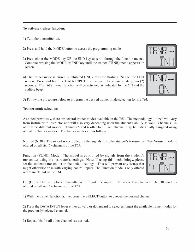
65
To activate trainer function:
1) Turn the transmitter on.
2) Press and hold the MODE button to access the programming mode.
3) Press either the MODE key OR the END key to scroll through the function menus. Continue pressing the MODE or END key until the trainer (TRNR) menu appears on screen.
screen. Press and hold the DATA INPUT lever upward for approximately two (2)
audible beep.
5) Follow the procedure below to program the desired trainer mode selection for the T6J.
Trainer mode selection:
As noted previously, there are several trainer modes available in the T6J. The methodology utilized will vary
one of the trainer modes. The trainer modes are as follows:
on Channels 1-4 of the T6J.
1) With the trainer function active, press the SELECT button to choose the desired channel.
2) Press the DATA INPUT lever either upward or downward to select amongst the available trainer modes for the previously selected channel.
3) Repeat this for all other channels as desired.
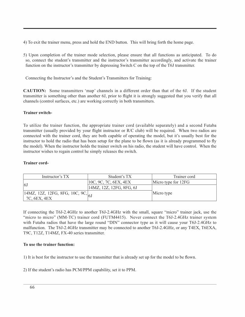
66
4) To exit the trainer menu, press and hold the END button. This will bring forth the home page.
5) Upon completion of the trainer mode selection, please ensure that all functions as anticipated. To do
CAUTION:
channels (control surfaces, etc.) are working correctly in both transmitters.
Trainer switch-
To utilize the trainer function, the appropriate trainer cord (available separately) and a second Futaba
the model). When the instructor holds the trainer switch on his radio, the student will have control. When the instructor wishes to regain control he simply releases the switch.
Trainer cord-
Trainer cord
6J10C, 9C, 7C, 6EX, 4EX Micro type for 12FG
14MZ, 12Z, 12FG, 8FG, 6JMicro type 14MZ, 12Z, 12FG, 8FG, 10C, 9C,
7C, 6EX, 4EX6J
malfunction. The T6J-2.4GHz transmitter may be connected to another T6J-2.4GHz, or any T4EX, T6EXA, T9C, T12Z, T14MZ, FX-40 series transmitter.
To use the trainer function:
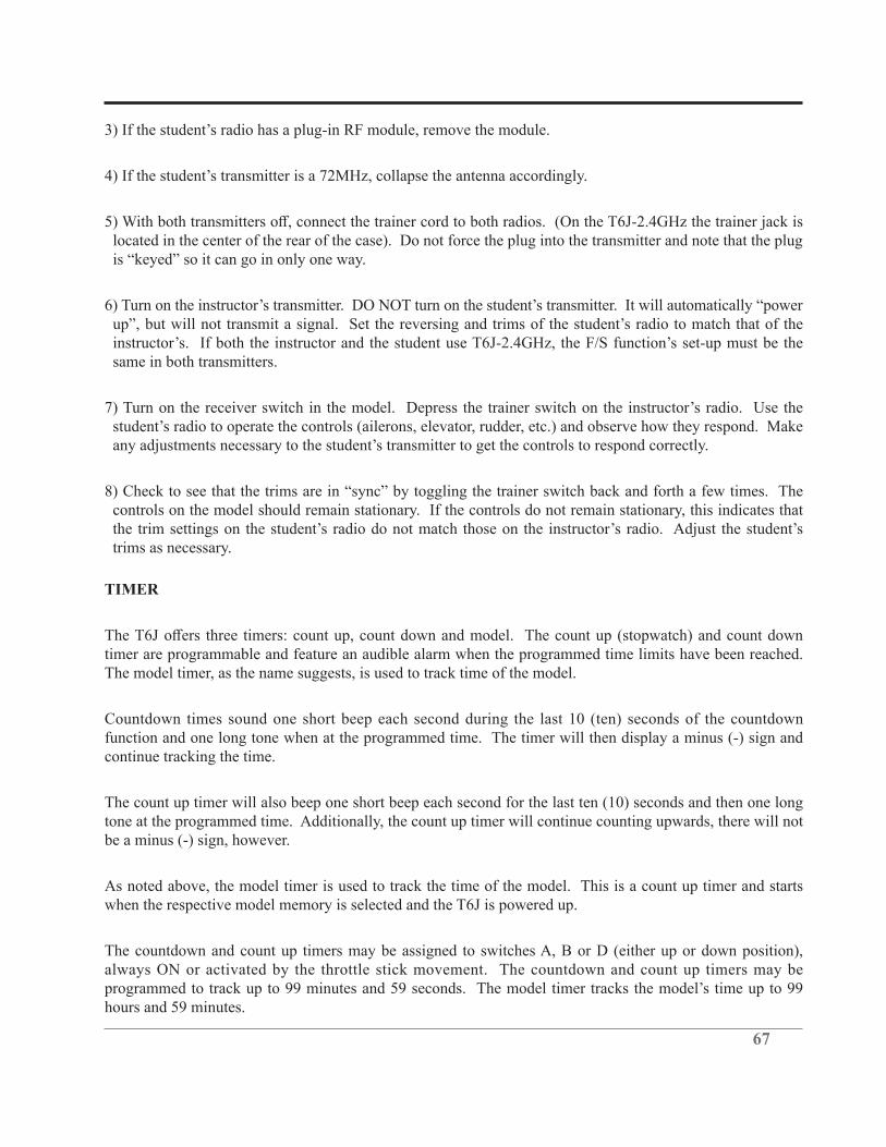
67
located in the center of the rear of the case). Do not force the plug into the transmitter and note that the plug
same in both transmitters.
controls on the model should remain stationary. If the controls do not remain stationary, this indicates that
trims as necessary.
TIMER
timer are programmable and feature an audible alarm when the programmed time limits have been reached. The model timer, as the name suggests, is used to track time of the model.
Countdown times sound one short beep each second during the last 10 (ten) seconds of the countdown function and one long tone when at the programmed time. The timer will then display a minus (-) sign and continue tracking the time.
The count up timer will also beep one short beep each second for the last ten (10) seconds and then one long tone at the programmed time. Additionally, the count up timer will continue counting upwards, there will not be a minus (-) sign, however.
As noted above, the model timer is used to track the time of the model. This is a count up timer and starts when the respective model memory is selected and the T6J is powered up.
The countdown and count up timers may be assigned to switches A, B or D (either up or down position), always ON or activated by the throttle stick movement. The countdown and count up timers may be
hours and 59 minutes.
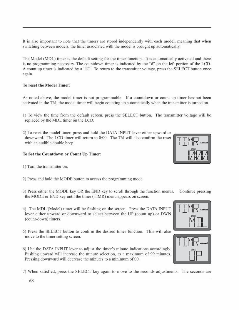
68
It is also important to note that the timers are stored independently with each model, meaning that when switching between models, the timer associated with the model is brought up automatically.
The Model (MDL) timer is the default setting for the timer function. It is automatically activated and there
again.
To reset the Model Timer:
As noted above, the model timer is not programmable. If a countdown or count up timer has not been activated in the T6J, the model timer will begin counting up automatically when the transmitter is turned on.
1) To view the time from the default screen, press the SELECT button. The transmitter voltage will be replaced by the MDL timer on the LCD.
2) To reset the model timer, press and hold the DATA INPUT lever either upward or
with an audible double beep.
To Set the Countdown or Count Up Timer:
1) Turn the transmitter on.
2) Press and hold the MODE button to access the programming mode.
3) Press either the MODE key OR the END key to scroll through the function menus. Continue pressing the MODE or END key until the timer (TIMR) menu appears on screen.
lever either upward or downward to select between the UP (count up) or DWN (count-down) timers.
move to the timer setting screen.
Pushing upward will increase the minute selection, to a maximum of 99 minutes. Pressing downward will decrease the minutes to a minimum of 00.
7) When satisfied, press the SELECT key again to move to the seconds adjustments. The seconds are
69
adjustable from a minimum of 00 to a maximum of 59.
8) Pressing SELECT once again will move to the timer starting method screen. Press the DATA INPUT lever upward or downward to select accordingly. The options are:
• • - SWA- Switch A(ON in the up position) • • - SWB- Switch B(ON in the up position) • • - SWD- Switch D(ON in the up position) • THR- Throttle stick movement activation, activates at approximately1/3 throttle • ON- The timer is always activated
Note: To stop the timer when activated, simply move the respective switch or stick to the opposite position.
the timer will stop accordingly. To reactivate the timer, move it to the up position once again.
To reset the timer, press and hold the DATA INPUT lever momentarily when the timer is displayed on the LCD.
9) Press and hold the END button to exit the programming menu.

70
FLOW CHART ACRO MODE FUNCTIONS (1/2)
Home screen
Programming mode
Timer display

71
FLOW CHART ACRO MODE FUNCTIONS (2/2)
MODE key
END key
SELECT key
DATA +/- lever

72
FLOW CHART HELI MODE FUNCTIONS (1/2)
Home screen
Timer display

73
FLOW CHART HELI MODE FUNCTIONS (2/2)
MODE key
END key
SELECT key
DATA +/- lever

74
Adjustable length control sticks
The control stick length is adjustable to make the transmitter more comfortable to hold and operate. To adjust the length, hold the locking piece (B) and turn the stick tip (A) counterclockwise. Turn the locking piece B up or down to lengthen or shorten the stick. When the length is as desired, lock the stick in position by turning locking piece B counterclockwise.
Changing the T6J Stick Mode
right control stick operates the aileron and elevator and the left stick operates the rudder and throttle. This is
1) Simultaneously depress the MODE and END keys, and then turn on the power.
2) Press the SELECT button until the stick (STCK) mode menu is on the LCD screen. The LCD screen will indicate the current stick mode selection (2).
3) Press the DATA INPUT lever upward or downward to change the stick modes. If a mode is selected that moves the throttle control to the right stick, the throttle detent mechanism will have to be moved as well. This can be done by the Futaba Service Center. (See Page 3).

75
FLYING SAFETY GUIDELINES
specifically intended for R/C model aircraft is highly recommended. In addition to joining a club, we
and instructors are available at AMA club sites to help you get started the right way. Contact the AMA at the address or toll-free phone number below:
Academy of Model Aeronautics5161 East Memorial Drive
Muncie, IN 47302-9252Tel: 1-(800)-435-9262Fax: 1-(765)-741-0057
Or via the internet at: http://www.modelaircraft.org
Charge the batteries
the state-of-charge of the batteries- especially the on-board receiver pack. Inadequate charging and failing to
of factors that determine receiver battery power consumption (such as the number and type of servos in your
hand-held volt meters available specially intended for R/C use. The Hobbico® Digital Voltmeter MKIII™ is one such unit. An on-board volt meter mounted directly on the model (HCAP0330) can also be used.

76
Flight Preparation
Check the controls
2) Mount the wing to the fuselage. Turn on the transmitter, then the receiver (remember to do this in reverse
the one on the LCD screen.
3) Operate and observe the controls. Look for inadvertent movement and listen for abnormal servo sounds.
interfere with each other.
4) One at a time, operate each control on the airplane using the sticks on the transmitter to make certain
Moisture may enter the transmitter through the antenna or stick openings and cause erratic operation or loss
or other waterproof cover.
77
GLOSSARY
• AFR (Adjustable function rate/high rate)
Adjusts the total travel in each direction of a particular function, such as ailerons. For example, used to
elevons, or other programming.
•
the drooped aileron which causes a model to yaw with aileron input.
• Ailerons
Hinged control surfaces located on the trailing edge of the wing, one on each side, which provide control of
roll or turn, the right-hand aileron is moved upward and the left-hand aileron downward, and vice versa for a left roll or turn.
• Airfoil
• Amphibian
type of aircraft. An amphibian can land on water and then extend the landing gear to allow it to pull up onto the shore. Many seaplane bases had ramps to allow the airplanes to pull up onto dry land parking areas.
• Angle of attack
The angle that the wing penetrates the air. As the angle of attack increases so does lift, up to a point (and drag).
• Area
area of a tapered wing is the wingspan multiplied by the average chord.
• Aspect Ratio
short aspect ratio (short wings) is better for maneuvering, since it allows a high roll rate. Short wings are also stronger than long wings. Gliders use high-aspect ratio wings (long, skinny wings) because they are
• Autorotation
The ability of a rotary-wing aircraft to land safely without engine power. This maneuver uses the stored energy in the rotor blades to produce lift at the end of decent, allowing the model to land safely.

78
• Axis
The line around which a body rotates.
• BEC (Battery Eliminator Circuitry)
Allows receiver to draw power from a main battery pack, eliminating the need for (and weight of) a receiver battery.
• Ball Bearing
• Ball Link
Connection using a ball, and a link which rotates on the ball. Used to connect the servo to a control surface or lever.
• Backlash
Term describing the amount of play between gears, or gear mesh. If too loose, the gear can slip, or strip the teeth. Too tight, and excessive wear is caused.
• Base Load Antenna
A rigid, short antenna mounted to the model. Used to replace the longer receiver antenna.
• Battery Fail safe function
Determines how to regain throttle control after a receiver low battery warning.
• Bell and Hiller
Control system used in helicopters. Changes pitch of blades in relation to their position via a swashplate. A
• Binding
What occurs when the friction at a joint is stronger than the linkage.
• Boring holes in the sky
•
his transmitter.
• CA
Abbreviation for cyanoacrylate. An instant type glue that is available in various viscosities (Thin, Medium, Thick, and Gel). These glues are ideal for the assembly of wood airplanes and other materials. NOTE: Most

79
CA glues will attack foam.
• CCPM
Cyclic-Collective-Pitch-Mixing. Type of swashplate mixing which requires a radio with CCPM mixing functions. This uses three servos to control the cyclic, while all three work together to raise and lower the swashplate for collective control. Please refer to the swashplate FAQ for further information.
• CG (Center of Gravity)
For modeling purposes, this is usually considered—the point at which the airplane balances fore to aft. This point is critical in regards to how the airplane reacts in the air. A tail-heavy plane will be very snappy but generally very unstable and susceptible to more frequent stalls. If the airplane is nose heavy, it will tend to track better and be less sensitive to control inputs, but, will generally drop its nose when the throttle is
nose heavy airplane will have to come in faster to land safely.
• Camber
surface, you get the mean airfoil line. Depending upon the airfoil, it can be straight or curved. This curve is
• Canard
word used to describe aircraft that have a main wing and a horizontal control surface in the nose...also
• CAMPac
Optional extended data storage module for certain Futaba transmitters.
• Carburetor
The part of the engine which controls the speed or throttle setting and lean/rich mixture via setting of the needle valve.
• Chandelle
A very steep climbing turn where the airplane makes a 180o change of direction.
• Channel
The number of functions your radio can control. Ex: an 8 channel radio has 8 available servo slots used for separate control surfaces or switches. These channels can also be mixed on many radios, for such functions as collective, which increases pitch when throttle is increased.
• Channel delay (Servo Slow/speed)
A feature within ATV which slows servo operation any time the radio is in the particular condition which has the delay set.
80
• Charge Jack
The plug receptacle of the switch harness into which the charger is plugged to charge the airborne battery.
is advisable to mount the charge jack in an accessible area of the fuselage so an ESV can be used without removing the wing.
• Charger
Device used to recharge batteries and usually supplied with the radio if NiCd batteries are included.
• Chord
determine wing area. May vary from root to tip.
• Collective pitch (Air only)
Used to regulate variable pitch props to slow model and keep engine running in vertical dives and provide
engine.
• Control Surface
Any one of the various moveable portions of the wings, tail surfaces, or canard.
• Conventional Gear
The landing gear arrangement where the airplane has a main gear and a tailwheel.
• Coreless motor
In a conventional servo, the motor has a steel core armature wrapped in wire that spins inside the magnets. In a coreless design, the armature uses a thin wire mesh that forms a cup that spins around the outside of the magnet eliminating the heavy steel core. A coreless motor does not have magnets as standard servo motors do, so they have a smoother, more constant, and stronger action. Regular servo motors have either 3 or 5 magnets (poles) which when the armature is between these, the servo motor is at its weakest.
• Cowl
smoothly around the front of the airplane, and also provides a proper path for cooling air around the engine.
• Cyclic
Term used for the horizontal controls used to determine the attitude of the helicopter. Also known as elevator and aileron.
• Dead Stick
stick”.
81
• Dialed In
where the mechanics and electronics work together to produce the best performance.
•
Uneven movement in each direction of a control surface. Usually used when discussing ailerons or when describing an undesired unevenness in movement of other controls.
• Digital
Please see the digital servo web page: http://www.futabarc.com/servos/digitalservos.html
• Dorsal Fin
• Drag
The air resistance to forward motion. Drag can be increased with the use of certain types of devices installed
large amounts of drag, while modern aircraft such as military jets, have very low drag.
• Dual Rates
A switch that can make controls more or less sensitive. Lower rates are better for beginners, who tend to overcontrol.
• Elevator
Hinged control surface located at the trailing edge of the horizontal stabilizer, which provides control of the airplane about the pitch axis and causes the airplane to climb or dive. The correct direction of control is to pull the transmitter elevator control stick back, toward the bottom of the transmitter, to move the elevator upward, which causes the airplane to climb, and vice versa to dive.
• Elevator-to-Flap Mixing
tighter loops or turns, etc.
• Elevon (Air only)
Used for delta wing and tailless aircraft which have 2 servos operating 2 aileron-like control surfaces as both elevator and aileron.
• Empennage
The vertical and horizontal tail surfaces of an airplane.
• Engine cut

82
Epoxy
A two-part resin/hardener glue that is extremely strong. It is generally available in 6 and 30-minute formulas. Used for critical points in the aircraft where high strength is necessary.
• Expanded Scale Voltmeter (ESV)
Device used to read the battery voltage of the on- board battery pack or transmitter battery pack.
• Exponential Rate
stick, but becomes increasing stronger as stick travel approaches 100%. Great for aerobatics and trouble situations.
• Fail Safe
A safety feature which turns a servo to a preset position if the signal is lost or interrupted. Additionally, battery fail-safe is a safety feature which brings the throttle servo down to idle as a warning that the receiver
• Fairing
wing fairing joins the wing and fuselage. A landing gear fairing streamlines the landing gear struts, and
• Field charger
A fast battery charger designed to work from a 12-volt power source, such as a car battery.
•
• Fin, Vertical Fin
• Flap-to-elevator mixing (Air and 2-servo gliders only)
• Flaperons
• Flaps
often found on scale models, but usually not on basic trainers.

83
• Flare
The point during the landing approach in which the pilot gives an increased amount of up elevator to smooth the touchdown of the airplane.
• Flight Box
• Flight Pack or Airborne Pack
All of the radio equipment installed in the airplane, i.e., Receiver, Servos, Battery, Switch harness.
• Floats
Long, canoe-shaped structures that allow an airplane to land on water. They are not a part of the aircraft
• Flutter
can sometimes cause the surface to break away from the aircraft and cause a crash. There are many reasons
control horns. If you ever hear a low-pitched buzzing sound, reduce throttle and land immediately.
• Flyback
Decrease in angle held by a servo which is being commanded by an AVCS gyro when the input is released.
released but the model has not yet turned as far as the AVCS gyro has read your input to tell it to move, the
slightly. This is perfectly normal.
• Flying Boat
The type of aircraft where the fuselage has the lower portion shaped like a power boat. The plane lands on
• Fore, Forward
movement....”
• Function menu
be moved to a switch by simply changing function assignments.
• Fuselage
The body of an airplane or helicopter.

84
• Gain
Gyro sensitivity. When too low, the tail will not hold position well. When too high, the surface being dampened by the gyro will tend to wag, or hunt for center.
• Glitch
Momentary radio problem that never happens unless you are over trees or a swamp.
• Glow Plug
The heat source for igniting the fuel/air mixture in the engine. When starting the engine a battery is used to
• Grease-in
A very smooth, gentle landing without a hint of a bounce.
• Gyro
A gyro is an electro-mechanical, or electronic device which aids in the control of an R/C model. The gyro senses motion in one axis, and directs the servo to counter that motion. The sensor, which can be a mechanical gyroscope, or an electronic piezo crystal, detects unwanted movement. The gyro then instructs the servo to counter for that motion. At all times, the radio commands will override the gyro command. The level of control the gyro had is adjusted by the GAIN setting.
Piezo Gyro: uses a piezo crystal to sense movement.
Non-Heading-hold vs. heading hold: A standard (nonHH) gyro senses movement and makes an effort to counter that movement as long as it feels it. Therefore, it is NOT going to return the model to the exact heading prior to the movement. Heading Hold (or AVCS) gyros will lock the model into one position, and accurately correct for movement by sensing rate of change and returning at that same rate. SMM technology: utilizes a microchip to sense movement and provide all readings. Experiences minimal
mechanical gyros.
• Gyro sensitivity
Used to create stick priority or activate each rate of a dual rate gyro based on stick position. This preprogrammed mix decreases the gain of the gyro directly proportional to the amount of rudder stick given (or steps the gyro down from high to low rate on dual rate gyros.)
• Heading Hold
This describes a type of Gyro which senses rotation, and maintains direction. This is accomplished by sensing the rate of motion, and the time of motion, then compensating for the distance. While this sounds
gyro on the yaw axis the model will continue to face north until you command it to yaw. See also Heading

85
• Heading Lock
Slang term for Heading Hold Gyro.
• Helicopter Radio
A remote control radio system designed specifically for use with helicopter models. The helicopter
necessity. Second is the throttle stick, which is ratcheted in airplane transmitters, will not have the clicking feel on the heli version. This is due to the precise control needed on the heli collective stick to achieve and
used will vary from helicopter to helicopter. Note that many radios produced have both airplane and helicopter programming in a single radio.
• Horizontal Stabilizer
The horizontal tail surface at the back of the fuselage which provides aerodynamic pitch stability to the airplane.
• Hover
To maintain a stationary position in which the model is not climbing, diving, rolling or yawing.
•
point when it is not exactly center throttle stick position.
• Hovering pitch (Heli programming only)
around center stick (or the hovering point if that point is not at center throttle stick, then the center-point of
• Idle Up
This is a setting on the transmitter which limits the throttle minimum. Particularly useful for FFF and 3D
• Immelmann
A maneuver originally used to reverse direction in combat. The airplane noses up and over onto its back. It then rolls upright and continues in the direction opposite to the original direction. It was invented by the World War I German pilot Max Immelmann, whose airplane could perform the maneuver, and others
their planes to perform the maneuver, too.
• Inhibit
Makes a feature inactive and unable to be used. When a function is inhibited, it cannot be used even if the

86
• Intake
An air inlet on an aircraft. You can have a carburetor intake, cooling intake, air conditioning intake (on full-
• Inverted
• Inverted Flight Control
Activates inverted flight programming for helis, which reverses the direction of the rudder, pitch and
hovering is seldom used. Instead, idle-ups are used and the modeler learns to understand and respond to the
• Landing Gear
• Lateral Balance
The left-right or side-to-side balance of an airplane. An airplane that is laterally balanced will track better through loops and other maneuvers.
• Leading Edge (LE)
• Linear Mix
Directly proportional.
• Loop
and around to describe a vertical circle in the air.
• Main Gear
Also Main Landing Gear. The large, heavy-duty landing gear struts and wheels that support most of the weight of the airplane. They are usually under the wing or under the fuselage near the center of the aircraft. Any other landing gear struts and wheels are noticeably smaller.
• Master Mix Mode
• Metal gears

87
Drive gears within a servo which are made of one or multiple metal types. Metal gears tend to wear more rapidly than nylon gears when in the same installation, and so require more frequent service to maintain
shock.
• Mixing
model and determining the direction and amount of elevator throw required to correct for this change, a
• NiCd = Nickel Cadmium battery
Rechargeable batteries which are typically used as power for radio transmitters and receivers.
• Nitro = Nitromethane
results. Nitro content in fuel is indicated by the percent of the fuel.
• Nose Gear
• Nylon gears
Drive gears within a servo are made of nylon. Nylon gears show slower wear than metal gears, but are more
• PPM
Pulse Position Modulation.
• Peak
This is the point at which a battery will no longer accept a charge, and converts the energy to heat. This is damaging to the battery pack, and potentially hazardous.
• Peak Charger
This type of charger will eliminate the guesswork. When the battery has reached peak, the charger reverts to a maintenance charge rate, which will not damage the pack.
• Pitch Axis
The airplane axis controlled by the elevator. Pitch is illustrated by holding the airplane at each wingtip. Raising or lowering the nose is the pitch movement. This is how the climb or dive is controlled.
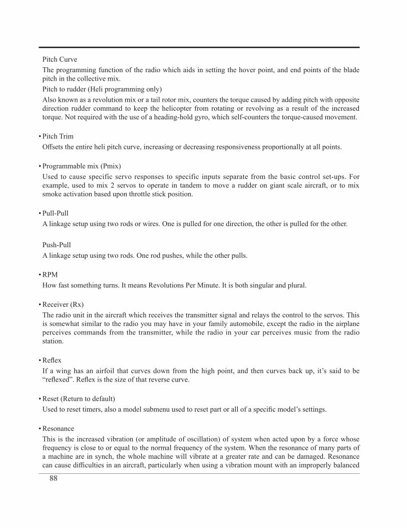
88
Pitch Curve
The programming function of the radio which aids in setting the hover point, and end points of the blade pitch in the collective mix.
Pitch to rudder (Heli programming only)
Also known as a revolution mix or a tail rotor mix, counters the torque caused by adding pitch with opposite direction rudder command to keep the helicopter from rotating or revolving as a result of the increased torque. Not required with the use of a heading-hold gyro, which self-counters the torque-caused movement.
• Pitch Trim
• Programmable mix (Pmix)
Used to cause specific servo responses to specific inputs separate from the basic control set-ups. For example, used to mix 2 servos to operate in tandem to move a rudder on giant scale aircraft, or to mix smoke activation based upon throttle stick position.
• Pull-Pull
A linkage setup using two rods or wires. One is pulled for one direction, the other is pulled for the other.
Push-Pull
A linkage setup using two rods. One rod pushes, while the other pulls.
• RPM
How fast something turns. It means Revolutions Per Minute. It is both singular and plural.
• Receiver (Rx)
The radio unit in the aircraft which receives the transmitter signal and relays the control to the servos. This is somewhat similar to the radio you may have in your family automobile, except the radio in the airplane perceives commands from the transmitter, while the radio in your car perceives music from the radio station.
•
• Reset (Return to default)
• Resonance
This is the increased vibration (or amplitude of oscillation) of system when acted upon by a force whose frequency is close to or equal to the normal frequency of the system. When the resonance of many parts of a machine are in synch, the whole machine will vibrate at a greater rate and can be damaged. Resonance

89
propeller/spinner.
For helis: Keep in mind that a helicopter has many rotating parts, and they all cause resonance. The helicopter will need to be tuned to reduce the amount of vibration.
• Retract Servo
ATV, EPA, or AST adjustments can be made on these servos because they are not proportional. The linkage
landing gear in a gear-up or gear-down position.
• Retracts
Short for retractable landing gear. Wheels and struts that fold up into the aircraft to get them out of the
• Revolution Mixing
The function of the radio which mixes throttle to rudder, preventing the rotation of the helicopter during throttle increase or decrease.
• Roll (maneuver)
The aircraft keeps the nose pointed in one direction while it rolls over on its back and then upright again.
• Roll Axis
The airplane axis controlled by the ailerons. Roll is illustrated by holding the airplane by the nose and tail. Dropping either wingtip is the roll movement. This is used to bank or turn the airplane. Many aircraft are not equipped with ailerons and the Roll and Yaw motions are controlled by the rudder. This is one reason why most trainer aircraft have a larger amount of dihedral.
• Rudder
Hinged control surface located at the trailing edge of the vertical stabilizer, which provides control of the airplane about the Yaw axis and causes the airplane to Yaw left or right. Left rudder movement causes the airplane to Yaw left, and right rudder movement causes it to Yaw right.
•
In radios with idle up functions, this specifies the amount of tail rotor pitch in the different idle up conditions.
• Rudder-to-Aileron
Mix used to counteract undesirable roll which often happens with rudder input, especially in knife edge, also called roll coupling.
• Rudder-to-Throttle
This heli mix adds a small amount of throttle to counter the added load on the main gear from increasing the pitch of the tail blades, helping to maintain a constant headspeed during rudder application. (This is a minor

90
Ruddervator
Ruddervators are on a v-tail. Both of the ruddervators move up and down for pitch control and both move left or right for yaw control.
• Rx
Abbreviation for receiver.
• SMT = Surface Mount Technology
• Seaplane
• Servo
The electro-mechanical device which moves the control surfaces or throttle of the aircraft according to commands from the receiver. The radio device which does the physical work inside the aircraft.
• Servo Reversing
• Servo Output Arm
The removable arm or wheel which bolts to the output shaft of a servo and connects to the pushrod.
• Slats
open and close automatically, depending upon airspeed and angle of attack.
• Slip
of descent without picking up a lot of speed.
• Slop
Unwanted, excessive free movement in a control system. Often caused by a hole in a servo arm or control horn that is too big for the pushrod wire or clevis pin. This condition allows the control surface to move
• Slot

91
• Slow Roll
A very slow version of the roll.
• Snap Roll
direction chosen by the pilot. Improper speed control during a landing approach can also make the model
and a crash results.
• Snap Roll Switch
• Solo
•
The widest straight-line distance between the two wingtips.
• Speed Brakes
Large panels that fold out of the aircraft structure to provide a lot of extra drag to the air. They are not part of the wing structure, but are usually mounted on the fuselage. Military jets most often have speed brakes, which fold out of the fuselage. Some airliners use spoilers as speed brakes when at altitude.
• Speed Flap
The middle control surface on a 6-trailing-edge-surface glider or the inboard control surface on a 4-surface glider.
• Spin
attack. This causes the airplane to rotate around its middle while it descends at a high rate of speed. When
crash when the pilot enters an accidental spin too close to the ground. This is caused by improper speed control during the landing approach.
• Spinner
the propeller hub and also makes the airplane looks much better.

92
• Split-S
• Spoiler(s)
drag to help with aerodynamic braking.
• Stabilator
• Stall
What happens when the angle of attack is too great to generate lift regardless of airspeed. (Every airfoil has an angle of attack at which it generates maximum lift—the airfoil will stall beyond this angle).
• Stick setting
• Strut
Basically this is a supporting member. A wing strut supports the wing, and goes from the fuselage to the wing. Cabane struts are on biplanes, and support the upper wing over the fuselage. A landing gear strut is the portion that holds the wheel assembly to the airplane, and away from the wing or fuselage.
• Sub-Trim
This is a trim function on many computer radios, allowing trim function during set-up, and still allowing the
• Swashplate adjustment (Heli programming only)
This feature includes swash-to-throttle mixing, used to add throttle during cyclic commands for constant engine RPM. It also includes swash rotation, used to correct for a model whose set-up has the swash plate
• Swashplate type (Heli programming only)
geometry does not match the positioning of the stock swash types.
• Tachometer
engine RPM.
93
• Taildragger
The nickname of an airplane that sits on its tail with the two main wheels in front and a tailwheel in the rear.
• Tailskid
On old World War I type aircraft, or pioneer-type aircraft, there was no tailwheel. A wooden skid was used to support the tail of the airplane. While this helps slow the airplane during landing, it is useless as an aid to steering on the ground. The real aircraft with tailskids had to be maneuvered on the ground by ground crews, who put the tail on a small cart and towed the airplane where they wanted it. For small distances, the tail was picked-up by hand and the airplane pushed into position by the ground crew.
• Tailwheel
The small wheel at the tail of the airplane. This is found on the type of airplane that have the two large wheels in the front, and the small one in the rear. The airplane sits on its tail.
• Throttle
The control that allows the pilot to change the speed of the engine.
• Throttle Curve
• Throttle Hold
hold the throttle in an idle. Useful when starting, as well as for autorotations.
• Thrust
• Torque
The force which tends to cause rotation.
• Trailing Edge (TE)
The rearmost edge of the wing or stabilizer.
• Trainer Airplane
• Trainer System

94
• Transmitter (Tx)
The hand-held radio controller. This is the unit that sends out the commands that you input.
Tricycle Gear
The landing gear arrangement where the airplane has main gear and a nose gear.
Trim menu
Used to memorize current digital trim positions, set trim type, % of trim delay when switching from
caused by adjustment to aircraft is now easily measured. To activate additional features of trim menu, select
• Tx
Abbreviation for transmitter.
• Undercamber
This means that the lower surface of the wing has a hollow curve when observed from front to back. A thin wing with a high camber will be undercambered.
• V-tail model Mixing (Air and gliders only)
Used on a V-tail model to have 2 servos operate 2 control surfaces as both rudder and elevator.
• Ventral Fin
A small vertical surface on the bottom of the aft fuselage. Usually a long, slim triangle that is narrow at the front, and widens toward the rear. It usually ends at the rudder hinge line.
• Vertical Fin
The non-moving surface that is perpendicular to the horizontal stabilizer and provides yaw stability. This is the surface to which the rudder attaches.
• Washout
An intentional twist in the wing, causing the wing tips to have a lower angle of attack than the wing root. In other words, the trailing edge is higher than the leading edge at the wing tips. Washout helps prevent tip
• Wheel Pants
• Wing
The main lifting surface of an airplane.

95
• Winglet
• Yaw
The nose-left and nose-right movement of the airplane. This is controlled by the rudder.
• Yaw Axis
The airplane axis controlled by the rudder. Yaw is illustrated by hanging the airplane level by a wire located at the center of gravity. Left or right movement of the nose is the Yaw movement.
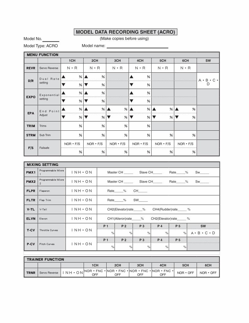
MENU FUNCTION
1CH 2CH 3CH 4CH 5CH 6CH SW
REVR Servo Reverse N・R N・R N・R N・R N・R N・R
D/RD u a l R a t e setting
▲ % ▲ % ▲ %A・B・C・
D▼ % ▼ % ▼ %
EXPOE x p o n e n t i a l setting
▲ % ▲ % ▲ %
▼ % ▼ % ▼ %
EPAE n d P o i n t Adjust
▲ % ▲ % ▲ % ▲ % ▲ % ▲ %
▼ % ▼ % ▼ % ▼ % ▼ % ▼ %
TRIM Trims % % % %
STRM Sub Trim % % % % % %
F/S FailsafeNOR・F/S NOR・F/S NOR・F/S NOR・F/S NOR・F/S NOR・F/S
% % % % % %
TRAINER FUNCTION
1CH 2CH 3CH 4CH 5CH 6CH
TRNR Servo Reverse INH・ON NOR・FNC・OFFNOR・FNC・
OFFNOR・FNC・
OFFNOR・FNC・
OFF NOR・OFF NOR・OFF
MIXING SETTING
PMX1Programmable Mixre
1INH・ON Master CH _____ Slave CH_____ Rate_____% Sw_____
PMX2Programmable Mixre
2INH・ON Master CH _____ Slave CH_____ Rate_____% Sw_____
FLPR Flaperon INH・ON Rate_____% CH_____
FLTR Flap Trim INH・ON Rate_____% SW_____
V-TL V-Tail INH・ON CH2(Elevator)rate_____% CH4(Rudder)rate_____ %
ELVN Elevon INH・ON CH1(Aileron)rate_____% CH2(Elevator)rate_____ %
T-CV Throttle Curves INH・ONP 1 P 2 P 3 P 4 P 5 SW
% % % % % A・B・C・D
P-CV Pitch Curves INH・ONP 1 P 2 P 3 P 4 P 5
% % % % %
MODEL DATA RECORDING SHEET (ACRO)(Make copies before using)
Model name:
Model No.
Model Type: ACRO

MENU FUNCTION
1CH 2CH 3CH 4CH 5CH 6CH SW
REVR Servo Reverse N・R N・R N・R N・R N・R N・R
D/RD u a l R a t e setting
▲ % ▲ % ▲ %A・ B・I-DL▼ % ▼ % ▼ %
EXPOE x p o n e n t i a l setting
▲ % ▲ % ▲ %
▼ % ▼ % ▼ %
EPAE n d P o i n t Adjust
▲ % ▲ % ▲ % ▲ % ▲ % ▲ %
▼ % ▼ % ▼ % ▼ % ▼ % ▼ %
TRIM Trims % % % %
STRM Sub Trim % % % % % %
F/S FailsafeNOR・F/S NOR・F/S NOR・F/S NOR・F/S NOR・F/S NOR・F/S
% % % % % %
TRAINER FUNCTION 1CH 2CH 3CH 4CH 5CH 6CH
TRNR Servo Reverse INH・ON NOR・FNC・OFFNOR・FNC・
OFFNOR・FNC・
OFFNOR・FNC・
OFF NOR・OFF NOR・OFF
MODEL DATA RECORDING SHEET (HELI)(Make copies before using)
Model name:
Model No.
Model Type: HELI
MIXING SETTING
N-THNormal Throttle
Curves
P 1 P 2 P 3 P 4 P 5
% % % % %
N-PINo rma l P i t c h
Curves
P 1 P 2 P 3 P 4 P 5
% % % % %
I-THIdle-UP Throttle
CurvesINH・ON
P 1 P 2 P 3 P 4 P 5 Sw
% % % % % C・A・B
I-PIId le-UP Pitch
Curves
P 1 P 2 P 3 P 4 P 5
% % % % %
HOLD Throttle Hold INH・ON Throttle hold position______%
H-PIH o l d P i t c h
Curves
P 1 P 2 P 3 P 4 P 5
% % % % %
REVOPitch-Rudder Mixing INH・ON▼ % ▲ %
GYRO Gyro Mixing INH・ON▼ % ▲ % Sw: A・B・I-DL
SW-TSwash-Throttle Mixing INH・ON
AIL ELE RUD
% % %
RING Swash Ring INH・ON %
SWSH Swash Types
Mode Mode AIL ELE PIT
H-1HR-3・H-3・HE3 % % %
DELYThrottle Pitch Dely INH・ON
CH3 CH6
% %
HOVP Hovering Pitch INH・ON Mode: NOR ・ N/I

98
FUTABA CORPORATION
oak kandakajicho 8F 3-4 Kandakajicho, Chiyoda-ku, Tokyo 101-0045, Japan
©FUTABA CORPORATION 2018, 5 (3)