Embed Size (px)
Citation preview
(Reference Translation)
B-1-4-M
Standard Specifications for Electrical Components and Materials
Tokyo Electric Power Company, Incorporated
Established in July 1959
Revised in December 2000
Revised in June 2001
(Functional standardization)
6D-33 LIGHT CROSS ARMS
DISCLAIMER: This translation may be used for reference purposes only. This English version is not an official translation of the original Japanese document. In cases where any differences occur between the English version and the original Japanese version, the Japanese version
shall prevail. This translation is subject to change without notice. Tokyo Electric Power Company, Incorporated shall accept no responsibility or liability for damage or loss caused by any error, inaccuracy, misunderstanding, or changes with regard to this translation.
Any reproduction and any use for other purposes is strictly prohibited. Tokyo Electric Power Company, Incorporated
(Reference Translation)
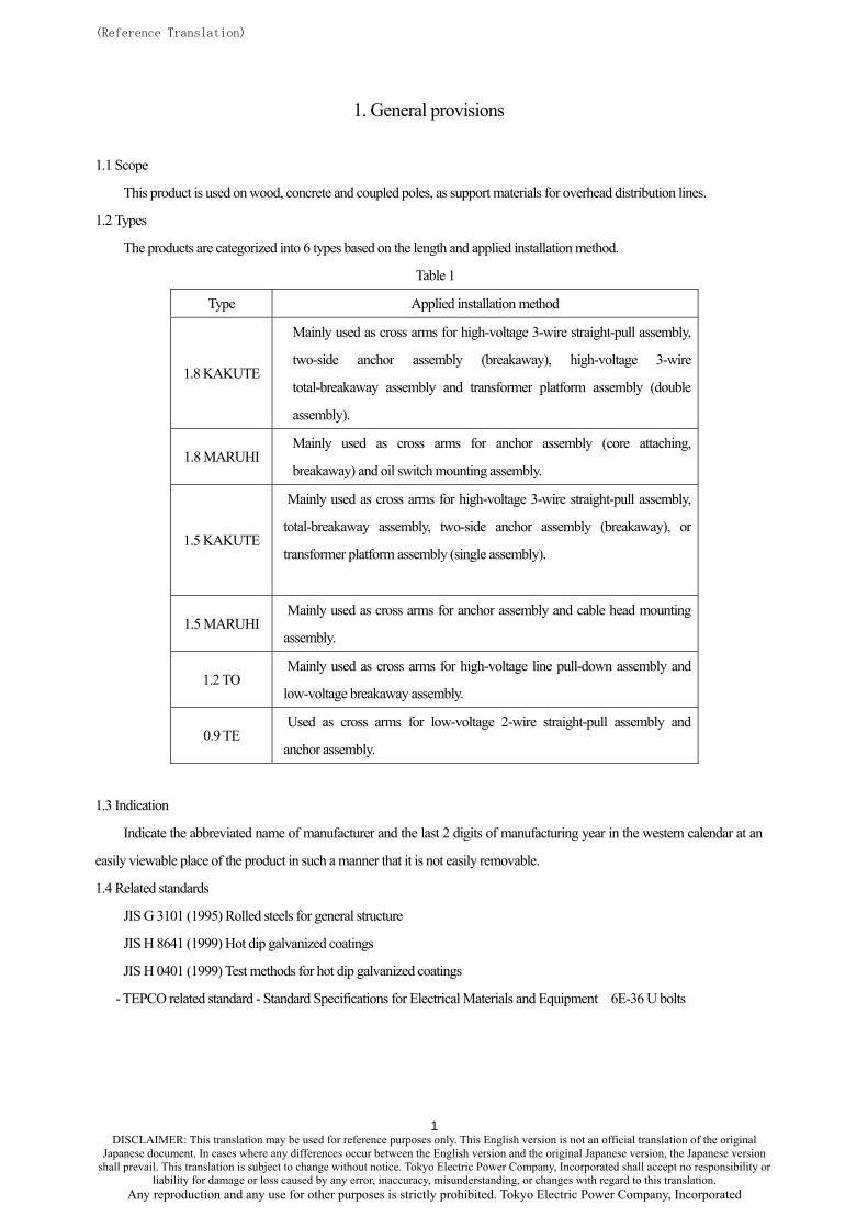
1. General provisions
1.1 Scope
This product is used on wood, concrete and coupled poles, as support materials for overhead distribution lines.
1.2 Types
The products are categorized into 6 types based on the length and applied installation method.
Table 1
Type Applied installation method
1.8 KAKUTE
Mainly used as cross arms for high-voltage 3-wire straight-pull assembly,
two-side anchor assembly (breakaway), high-voltage 3-wire
total-breakaway assembly and transformer platform assembly (double
assembly).
1.8 MARUHI Mainly used as cross arms for anchor assembly (core attaching,
breakaway) and oil switch mounting assembly.
1.5 KAKUTE
Mainly used as cross arms for high-voltage 3-wire straight-pull assembly,
total-breakaway assembly, two-side anchor assembly (breakaway), or
transformer platform assembly (single assembly).
1.5 MARUHI Mainly used as cross arms for anchor assembly and cable head mounting
assembly.
1.2 TO Mainly used as cross arms for high-voltage line pull-down assembly and
low-voltage breakaway assembly.
0.9 TE Used as cross arms for low-voltage 2-wire straight-pull assembly and
anchor assembly.
1.3 Indication
Indicate the abbreviated name of manufacturer and the last 2 digits of manufacturing year in the western calendar at an
easily viewable place of the product in such a manner that it is not easily removable.
1.4 Related standards
JIS G 3101 (1995) Rolled steels for general structure
JIS H 8641 (1999) Hot dip galvanized coatings
JIS H 0401 (1999) Test methods for hot dip galvanized coatings
- TEPCO related standard - Standard Specifications for Electrical Materials and Equipment 6E-36 U bolts
DISCLAIMER: This translation may be used for reference purposes only. This English version is not an official translation of the original
1
Japanese document. In cases where any differences occur between the English version and the original Japanese version, the Japanese version shall prevail. This translation is subject to change without notice. Tokyo Electric Power Company, Incorporated shall accept no responsibility or
liability for damage or loss caused by any error, inaccuracy, misunderstanding, or changes with regard to this translation. Any reproduction and any use for other purposes is strictly prohibited. Tokyo Electric Power Company, Incorporated
(Reference Translation)
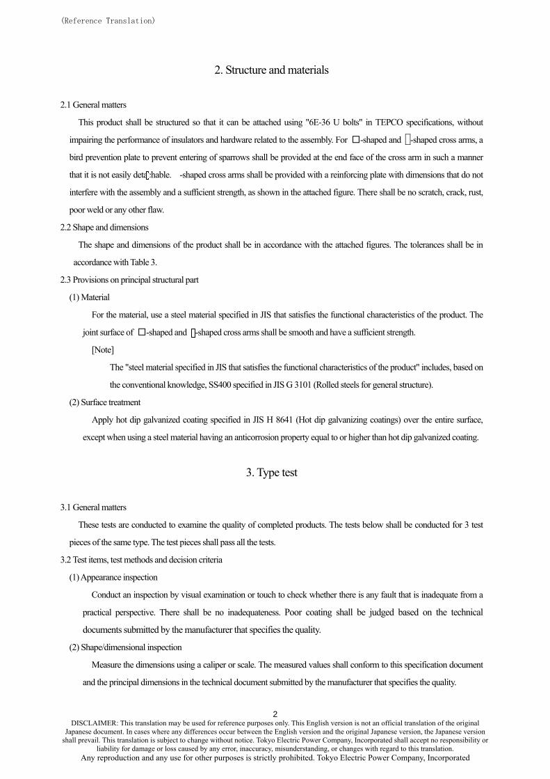
2. Structure and materials
2.1 General matters
This product shall be structured so that it can be attached using "6E-36 U bolts" in TEPCO specifications, without
impairing the performance of insulators and hardware related to the assembly. For □-shaped and -shaped cross arms, a
bird prevention plate to prevent entering of sparrows shall be provided at the end face of the cross arm in such a manner
that it is not easily detachable. -shaped cross arms shall be provided with a reinforcing plate with dimensions that do not
interfere with the assembly and a sufficient strength, as shown in the attached figure. There shall be no scratch, crack, rust,
poor weld or any other flaw.
2.2 Shape and dimensions
The shape and dimensions of the product shall be in accordance with the attached figures. The tolerances shall be in
accordance with Table 3.
2.3 Provisions on principal structural part
(1) Material
For the material, use a steel material specified in JIS that satisfies the functional characteristics of the product. The
joint surface of □-shaped and -shaped cross arms shall be smooth and have a sufficient strength.
[Note]
The "steel material specified in JIS that satisfies the functional characteristics of the product" includes, based on
the conventional knowledge, SS400 specified in JIS G 3101 (Rolled steels for general structure).
(2) Surface treatment
Apply hot dip galvanized coating specified in JIS H 8641 (Hot dip galvanizing coatings) over the entire surface,
except when using a steel material having an anticorrosion property equal to or higher than hot dip galvanized coating.
3. Type test
3.1 General matters
These tests are conducted to examine the quality of completed products. The tests below shall be conducted for 3 test
pieces of the same type. The test pieces shall pass all the tests.
3.2 Test items, test methods and decision criteria
(1) Appearance inspection
Conduct an inspection by visual examination or touch to check whether there is any fault that is inadequate from a
practical perspective. There shall be no inadequateness. Poor coating shall be judged based on the technical
documents submitted by the manufacturer that specifies the quality.
(2) Shape/dimensional inspection
Measure the dimensions using a caliper or scale. The measured values shall conform to this specification document
and the principal dimensions in the technical document submitted by the manufacturer that specifies the quality.
DISCLAIMER: This translation may be used for reference purposes only. This English version is not an official translation of the original
2
Japanese document. In cases where any differences occur between the English version and the original Japanese version, the Japanese version shall prevail. This translation is subject to change without notice. Tokyo Electric Power Company, Incorporated shall accept no responsibility or
liability for damage or loss caused by any error, inaccuracy, misunderstanding, or changes with regard to this translation. Any reproduction and any use for other purposes is strictly prohibited. Tokyo Electric Power Company, Incorporated
(Reference Translation)
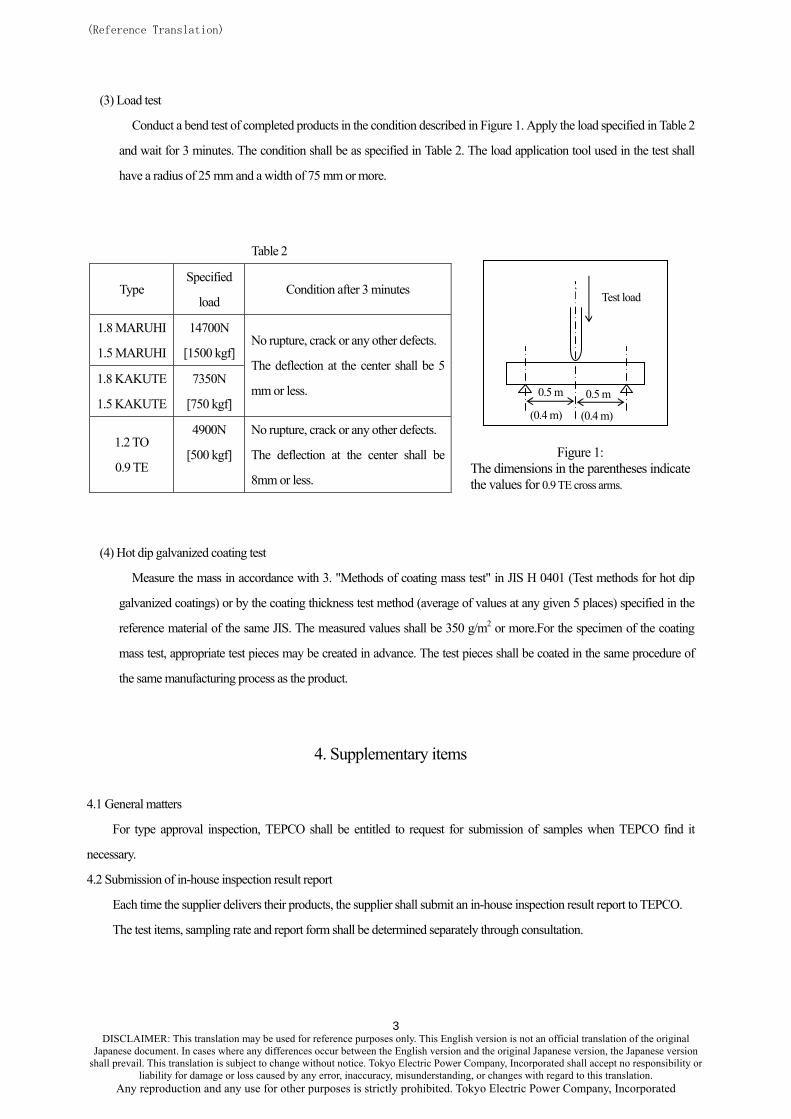
(3) Load test
Conduct a bend test of completed products in the condition described in Figure 1. Apply the load specified in Table 2
and wait for 3 minutes. The condition shall be as specified in Table 2. The load application tool used in the test shall
have a radius of 25 mm and a width of 75 mm or more.
Table 2
(0.4 m)
0.5 m
(0.4 m)
0.5 m
Test load
Type
Specified
load Condition after 3 minutes
1.8 MARUHI
1.5 MARUHI
14700N
[1500 kgf]
1.8 KAKUTE
1.5 KAKUTE
7350N
[750 kgf]
No rupture, crack or any other defects.
The deflection at the center shall be 5
mm or less.
1.2 TO
0.9 TE
4900N
[500 kgf]
No rupture, crack or any other defects.
The deflection at the center shall be
8mm or less.
Figure 1: The dimensions in the parentheses indicate the values for 0.9 TE cross arms.
(4) Hot dip galvanized coating test
Measure the mass in accordance with 3. "Methods of coating mass test" in JIS H 0401 (Test methods for hot dip
galvanized coatings) or by the coating thickness test method (average of values at any given 5 places) specified in the
reference material of the same JIS. The measured values shall be 350 g/m2 or more.For the specimen of the coating
mass test, appropriate test pieces may be created in advance. The test pieces shall be coated in the same procedure of
the same manufacturing process as the product.
4. Supplementary items
4.1 General matters
For type approval inspection, TEPCO shall be entitled to request for submission of samples when TEPCO find it
necessary.
4.2 Submission of in-house inspection result report
Each time the supplier delivers their products, the supplier shall submit an in-house inspection result report to TEPCO.
The test items, sampling rate and report form shall be determined separately through consultation.
DISCLAIMER: This translation may be used for reference purposes only. This English version is not an official translation of the original
3
Japanese document. In cases where any differences occur between the English version and the original Japanese version, the Japanese version shall prevail. This translation is subject to change without notice. Tokyo Electric Power Company, Incorporated shall accept no responsibility or
liability for damage or loss caused by any error, inaccuracy, misunderstanding, or changes with regard to this translation. Any reproduction and any use for other purposes is strictly prohibited. Tokyo Electric Power Company, Incorporated

(Reference Translation)
Table 3: Dimensional tolerances
(Unit: mm)
Positions of cross-sectional positions
Dimensional position Tolerance
A +/-1.5 mm
B +/-1.5 mm
C +/-1.5 mm
D +/-1.5 mm
E +/-0.23 mm
F +/-0.32 mm
G +/-1.5º (For -shaped type, it shall be within the range causing no practical
harm.)
Total length +/-0.5%
Hole diameter Round hole: +0.5 mm, -0 mm Long hole: +4.0 mm, -0 mm
Hole interval 100 mm or less: +/-2% More than 100 mm: +/-1%
Vertical and horizontal
deflection from the hole
center
+/-1.5 mm
Between the center of end
hole and an end +/-10 mm
Other +/-2%
Angular distortion 10 mm or less
(Note) Angular distortion shall be identified by measuring the longitudinal curvature in the surface that is parallel to
the flat plate part, as shown in the figure below.
DISCLAIMER: This translation may be used for reference purposes only. This English version is not an official translation of the original
4
Japanese document. In cases where any differences occur between the English version and the original Japanese version, the Japanese version shall prevail. This translation is subject to change without notice. Tokyo Electric Power Company, Incorporated shall accept no responsibility or
liability for damage or loss caused by any error, inaccuracy, misunderstanding, or changes with regard to this translation. Any reproduction and any use for other purposes is strictly prohibited. Tokyo Electric Power Company, Incorporated
(Reference Translation)
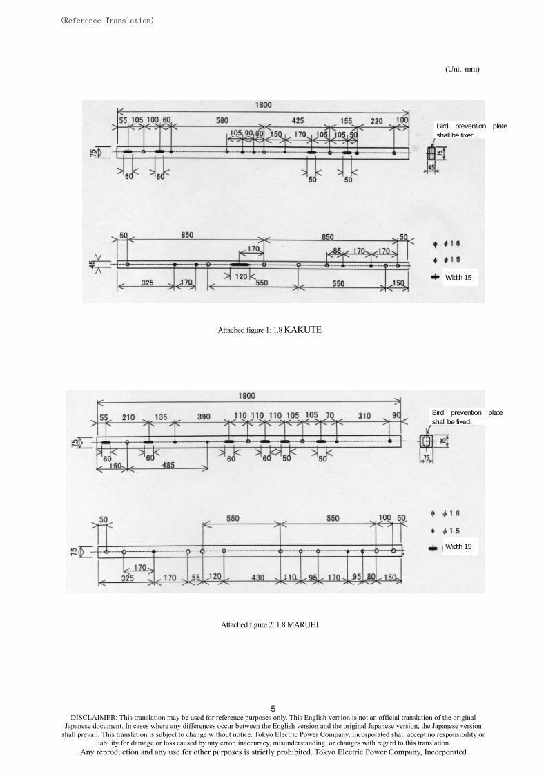
(Unit: mm)
Attached figure 2 Light cross arm 1.8 □TE
Width 15
Bird prevention plate shall be fixed.
Attached figure 1: 1.8 KAKUTE
Width 15
Bird prevention plate shall be fixed.
Attached figure 2: 1.8 MARUHI
DISCLAIMER: This translation may be used for reference purposes only. This English version is not an official translation of the original
5
Japanese document. In cases where any differences occur between the English version and the original Japanese version, the Japanese version shall prevail. This translation is subject to change without notice. Tokyo Electric Power Company, Incorporated shall accept no responsibility or
liability for damage or loss caused by any error, inaccuracy, misunderstanding, or changes with regard to this translation. Any reproduction and any use for other purposes is strictly prohibited. Tokyo Electric Power Company, Incorporated

(Reference Translation)
(Unit: mm)
DISCLAIMER: This translation may be used for reference purposes only. This English version is not an official translation of the original
6
Width 15
Bird prevention plate shall be fixed.
Attached figure 3: 1.5 KAKUTE
Bird prevention plate shall be fixed.
Width 15
Attached figure 4: 1.5 MARUHI
Japanese document. In cases where any differences occur between the English version and the original Japanese version, the Japanese version shall prevail. This translation is subject to change without notice. Tokyo Electric Power Company, Incorporated shall accept no responsibility or
liability for damage or loss caused by any error, inaccuracy, misunderstanding, or changes with regard to this translation. Any reproduction and any use for other purposes is strictly prohibited. Tokyo Electric Power Company, Incorporated

(Reference Translation)
DISCLAIMER: This translation may be used for reference purposes only. This English version is not an official translation of the original
Japanese document. In cases where any differences occur between the English version and the original Japanese version, the Japanese version shall prevail. This translation is subject to change without notice. Tokyo Electric Power Company, Incorporated shall accept no responsibility or
liability for damage or loss caused by any error, inaccuracy, misunderstanding, or changes with regard to this translation. Any reproduction and any use for other purposes is strictly prohibited. Tokyo Electric Power Company, Incorporated
7
(Unit: mm)
Width 15
Attached figure 5: 1.2 TO
Width 15
Attached figure 6: 0.9 TE