Embed Size (px)
Citation preview

Installation Guide
RTH8500Touchscreen Programmable Thermostat
69-1902ES-1
Read and save these instructions.
MERCURY NOTICE: Do not place your old thermostat in the trash if it contains mercury in a sealed tube. Contact your local waste management authority for instructions regarding recycling and proper disposal.
Need Help?For assistance with this product please visit http://yourhome.honeywell.com
or call Honeywell Customer Care toll-free at 1-800-468-1502
® U.S. Registered Trademark. US Patent 6595430, D520,386 and other patents pending.
Copyright © 2007 Honeywell International Inc. All rights reserved.
This thermostat provides control of 24 VAC heating and cooling systems, or 750mV heating systems.
This thermostat contains a Lithium battery which may contain Perchlorate material.Perchlorate Material—special handling may apply,See www.dtsc.ca.gov/hazardouswaste/perchlorate

�
Getting startedInstallation tips ...........................................2Pre-installation checklist ...........................3
Old thermostat removalRemove old thermostat .............................5Identify and label wires ..............................6
New thermostat installationWallplate mounting ....................................7Wire connections .....................................10Battery installation ...................................13Thermostat mounting ..............................14Time/date settings ...................................15
System setupHow to change settings...........................16System settings ..................................17-23
AppendicesIn case of difficulty...................................24Customer assistance ...............................27Limited warranty ......................................28
Table of contents
RTH8500

Installation Guide
�
About your new thermostatInstallation is easy—even if you’ve never done it before!
Your new thermostat has been designed for fast, easy installation. Just follow the simple, step-by-step instructions in the following pages.
Install in three simple steps• Label wires and remove your old thermostat (see pages 5-6).• Install and wire your new thermostat (see pages 7-15).• Set your new thermostat to match your heating/cooling system
(see pages 16-23).
Installation tips• Have everything you need ready to go before you begin (see pages 3-4).• Do not use wire color as a guide. Use wire labels instead (see page 6).
TURN OFF POWER at heating/cooling system (or fuse/circuit-breaker panel) before you begin installation.
RTH8500
�
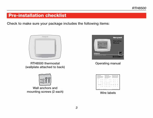
About your new thermostatPre-installation checklist
Check to make sure your package includes the following items:
RTH8500 thermostat (wallplate attached to back)
Wire labels
Wall anchors and
mounting screws (2 each)
Operating manual
Installation Guide
�
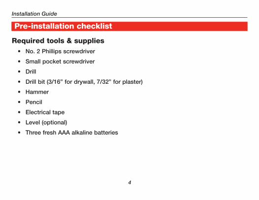
About your new thermostatPre-installation checklist
Required tools & supplies• No. 2 Phillips screwdriver
• Small pocket screwdriver
• Drill
• Drill bit (3/16” for drywall, 7/32” for plaster)
• Hammer
• Pencil
• Electrical tape
• Level (optional)
• Three fresh AAA alkaline batteries
RTH8500
5
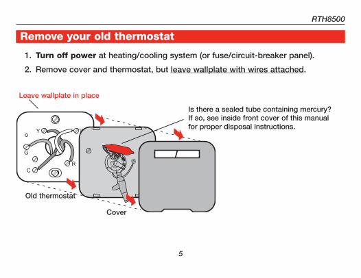
About your new thermostatRemove your old thermostat
1. Turn off power at heating/cooling system (or fuse/circuit-breaker panel).
2. Remove cover and thermostat, but leave wallplate with wires attached.
Is there a sealed tube containing mercury? If so, see inside front cover of this manual for proper disposal instructions.
Old thermostat
Cover
Leave wallplate in place
Installation Guide
�
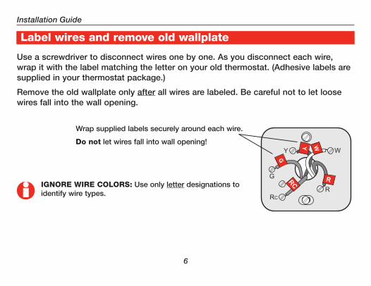
About your new thermostatLabel wires and remove old wallplate
Use a screwdriver to disconnect wires one by one. As you disconnect each wire, wrap it with the label matching the letter on your old thermostat. (Adhesive labels are supplied in your thermostat package.)
Remove the old wallplate only after all wires are labeled. Be careful not to let loose wires fall into the wall opening.
Wrap supplied labels securely around each wire.
Do not let wires fall into wall opening!
IGNORE WIRE COLORS: Use only letter designations to identify wire types.
RTH8500
�
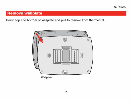
About your new thermostatRemove wallplate
Grasp top and bottom of wallplate and pull to remove from thermostat.
+
+ +
Wallplate

Installation Guide
8
About your new thermostatMark wallplate mounting position
1. Pull wires through wallplate.
2. Level wallplate if desired. 3. Mark positions of both screw holes.
RTH8500
�
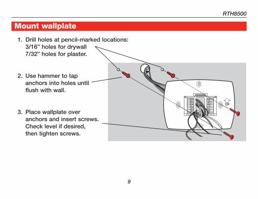
About your new thermostatMount wallplate
1. Drill holes at pencil-marked locations: 3/16” holes for drywall 7/32” holes for plaster.
2. Use hammer to tap anchors into holes until flush with wall.
3. Place wallplate over anchors and insert screws. Check level if desired, then tighten screws.
Installation Guide
�0
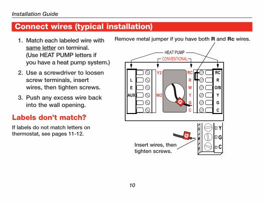
About your new thermostatConnect wires (typical installation)
1. Match each labeled wire with same letter on terminal. (Use HEAT PUMP letters if you have a heat pump system.)
2. Use a screwdriver to loosen screw terminals, insert wires, then tighten screws.
3. Push any excess wire back into the wall opening.
Remove metal jumper if you have both R and Rc wires.
Labels don’t match?If labels do not match letters on thermostat, see pages 11-12.
Insert wires, then tighten screws.

RTH8500
��
About your new thermostatIf labels do not match terminals, connect wires as shown here (see notes, below).
Remove metal jumper connecting R and Rc only if you must connect both R and Rc wires.
If your old thermostat had both R and RH wires, remove metal jumper. Connect the R wire to the Rc terminal, and the RH wire to the R terminal.
If your old thermostat had only 1 C or C1 wire, connect it to the C terminal. If your old thermostat had 2 C or C1 wires, wrap each separately with electrical tape and do not connect them.
Alternate wiring (conventional systems)
RC
R
W
Y
G
C
Y2
W2
Rc
R
W
Y
G
C
Y2
W2
2
3
2
Installation Guide
��
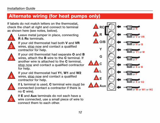
About your new thermostatIf labels do not match letters on the thermostat, check the chart at right and connect to terminal as shown here (see notes, below).
Leave metal jumper in place, connecting R & Rc terminals.If your old thermostat had both V and VR wires, stop now and contact a qualified contractor for help.If your old thermostat had separate O and B wires, attach the B wire to the C terminal. If another wire is attached to the C terminal, stop now and contact a qualified contractor for help.If your old thermostat had Y1, W1 and W2 wires, stop now and contact a qualified contractor for help.If L terminal is used, C terminal wire must be connected (contact a contractor if there is no C wire).If E and Aux terminals do not each have a wire connected, use a small piece of wire to connect them to each other.
Alternate wiring (for heat pumps only)
2
3
3
4
5
5
6
6
5
6
RTH8500
��
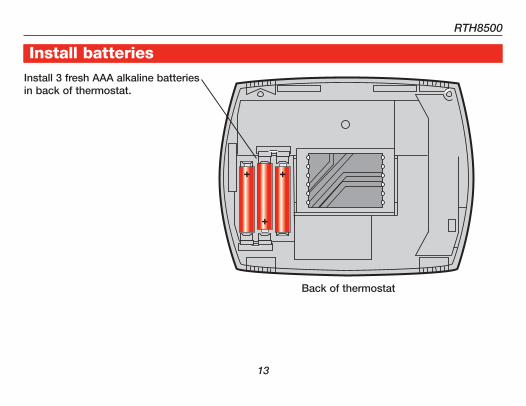
About your new thermostatInstall batteriesInstall 3 fresh AAA alkaline batteries in back of thermostat.
Back of thermostat

Installation Guide
��
About your new thermostatRemove tab and mount thermostat
TIP: If wires interfere when you try to mount the thermostat, push excess wire back into the wall opening.
Remove tab.
Align pins on back of thermostat with slots in wallplate, then push gently until thermostat snaps into place.
RTH8500
�5
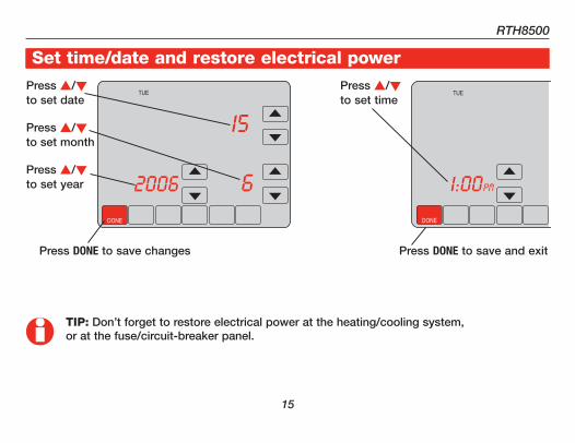
About your new thermostatSet time/date and restore electrical powerPress s/t to set date
Press s/t to set month
Press s/t to set year
TIP: Don’t forget to restore electrical power at the heating/cooling system, or at the fuse/circuit-breaker panel.
Press s/t to set time
Press DONE to save changes Press DONE to save and exit
DONE
TUE
15
62006
DONE
TUE
6PM1:00

Installation Guide
��
About your new thermostatSystem setup
2. Press and hold blank center key until the display changes.
1. Press SYSTEM.
Press s/t to select function
Function Setting
Press s/t to change setting
SCHED HOLD SCREEN MORE
TUE
AM
FollowingSchedule
Inside
Outside
Set To70
6:01
70
43
FAN
AUTO
SYSTEM
HEAT
DONE
TUE
Inside Set To70
0120
70
20
FAN
AUTO
DONE CANCEL
TUE
AM
Inside Set To70
6:01
70FAN
AUTO
SYSTEM
HEAT
3. Change settings as required (see pages 17-23).
4. Press DONE to exit & save changes.
NOTE: Because of choices you make while programming, some functions in the following pages may not appear.

RTH8500
��
About your new thermostatSystem setup
Year setting (first two digits)Function 0120
Press s/t to change the first two digits of the year:
Options: 20 = Year 20xx 21 = Year 21xx
Year setting (second two digits)Function 0130
Press s/t to change the last two digits of the year:
Options: 01 - 99 (i.e., 2001 - 2099)
Month settingFunction 0140
Press s/t to change the current month:
Options: 01 - 12 (i.e., January - December)
Date settingFunction 0150
Press s/t to change the current date:
Options: 01 - 31

Installation Guide
�8
About your new thermostat
Select system typeFunction 0170
Press s/t to select your system type:
Options: 1 Heat/cool: Gas, oil or electric heating with central air conditioning.2 Heat pump: Single-stage heat pump (no backup or auxiliary heat).3 Heat only: Gas, oil or electric heat without central air conditioning.4 Heat only with fan: Gas, oil or electric heat without central air conditioning.5 Hot water heat (no fan): Gas, oil or hot water heat without central air
conditioning.6 Cool only: Central air conditioning only.7 Multi-stage heat pump: Heat pump with backup or auxiliary heating.8 Conventional multi-stage system: 2 heat stages (wires on W and W2),
2 cooling stages (wires on Y and Y2).9 Conventional multi-stage system: 2 heat stages (wires on W and W2),
1 cooling stage (wire on Y).10 Conventional multi-stage system: 1 heat stage (wire on W), 2 cooling
stages (wires on Y and Y2).
System setup
RTH8500
��
About your new thermostatSystem setup
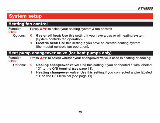
Heating fan controlFunction 0180
Press s/t to select your heating system & fan control:
Options: 0 Gas or oil heat: Use this setting if you have a gas or oil heating system (system controls fan operation).
1 Electric heat: Use this setting if you have an electric heating system (thermostat controls fan operation).
Heat pump changeover valve (for heat pumps only)Function 0190
Press s/t to select whether your changeover valve is used in heating or cooling:
Options: 0 Cooling changeover valve: Use this setting if you connected a wire labeled “O” to the O/B terminal (see page 11).
1 Heating changeover valve: Use this setting if you connected a wire labeled “B” to the O/B terminal (see page 11).
Installation Guide
�0
About your new thermostatSystem setup
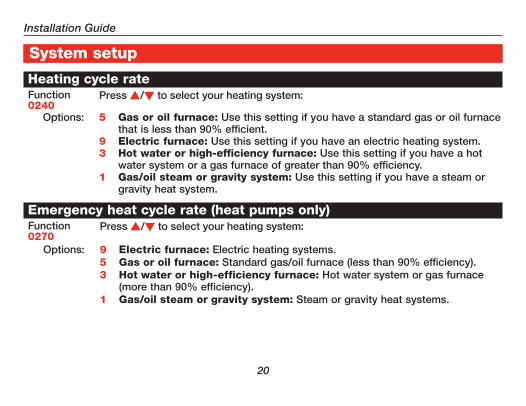
Heating cycle rateFunction 0240
Press s/t to select your heating system:
Options: 5 Gas or oil furnace: Use this setting if you have a standard gas or oil furnace that is less than 90% efficient.
9 Electric furnace: Use this setting if you have an electric heating system.3 Hot water or high-efficiency furnace: Use this setting if you have a hot
water system or a gas furnace of greater than 90% efficiency.1 Gas/oil steam or gravity system: Use this setting if you have a steam or
gravity heat system.
Emergency heat cycle rate (heat pumps only)Function 0270
Press s/t to select your heating system:
Options: 9 Electric furnace: Electric heating systems.5 Gas or oil furnace: Standard gas/oil furnace (less than 90% efficiency).3 Hot water or high-efficiency furnace: Hot water system or gas furnace
(more than 90% efficiency).1 Gas/oil steam or gravity system: Steam or gravity heat systems.
RTH8500
��
About your new thermostatSystem setup
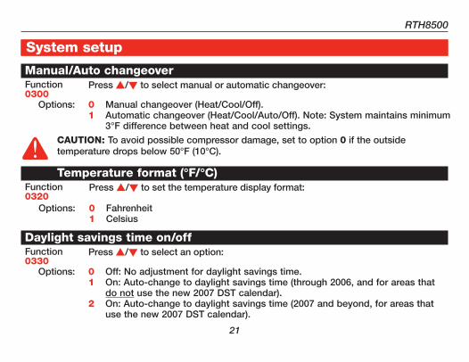
Manual/Auto changeoverFunction 0300
Press s/t to select manual or automatic changeover:
Options: 0 Manual changeover (Heat/Cool/Off).1 Automatic changeover (Heat/Cool/Auto/Off). Note: System maintains minimum
3°F difference between heat and cool settings.
Temperature format (°F/°C)Function 0320
Press s/t to set the temperature display format:
Options: 0 Fahrenheit1 Celsius
Daylight savings time on/offFunction 0330
Press s/t to select an option:
Options: 0 Off: No adjustment for daylight savings time.1 On: Auto-change to daylight savings time (through 2006, and for areas that
do not use the new 2007 DST calendar).2 On: Auto-change to daylight savings time (2007 and beyond, for areas that
use the new 2007 DST calendar).
CAUTION: To avoid possible compressor damage, set to option 0 if the outside temperature drops below 50°F (10°C).

Installation Guide
��
About your new thermostatSystem setup
Furnace filter change reminderFunction 0500
This feature displays an alert to remind you to change the furnace filter. Press s/t to set the desired reminder interval:
Options: 0 Off (no reminder to change furnace filter) 1 Reminder after 10-day run time (about 1 month)2 Reminder after 30-day run time (about 3 months)3 Reminder after 60-day run time (about 6 months)4 Reminder after 90-day run time (about 9 months)5 Reminder after 120-day run time (about 1 year)6 Reminder after 365-day run time (about 3 years)
Note: Press RESET to cancel the alert.
RTH8500
��
About your new thermostatSystem setup
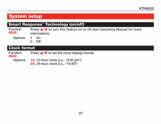
Smart Response® Technology (on/off)Function 0530
Press s/t to turn this feature on or off (see Operating Manual for more information):
Options: 1 On0 Off
Clock formatFunction 0640
Press s/t to set the clock display format:
Options: 12 12-hour clock (i.e., “3:30 pm”)24 24-hour clock (i.e., “15:30”)
Installation Guide
��
About your new thermostatIn case of difficulty
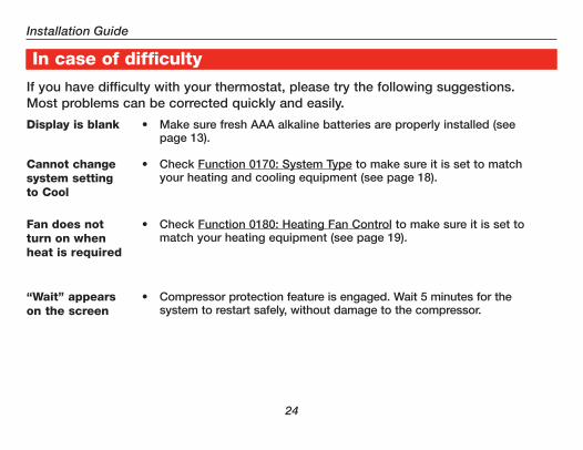
If you have difficulty with your thermostat, please try the following suggestions. Most problems can be corrected quickly and easily.
Display is blank • Make sure fresh AAA alkaline batteries are properly installed (see page 13).
Cannot change system setting to Cool
• Check Function 0170: System Type to make sure it is set to match your heating and cooling equipment (see page 18).
Fan does not turn on when heat is required
• Check Function 0180: Heating Fan Control to make sure it is set to match your heating equipment (see page 19).
“Wait” appears on the screen
• Compressor protection feature is engaged. Wait 5 minutes for the system to restart safely, without damage to the compressor.
RTH8500
�5
About your new thermostatIn case of difficultyHeating or cooling system does not respond
• Press SYSTEM to set system to Heat. Make sure the temperature is set higher than the Inside temperature.
• Press SYSTEM to set system to Cool. Make sure the temperature is set lower than the Inside temperature.
• Check circuit breaker and reset if necessary.• Make sure power switch at heating & cooling system is on.• Make sure furnace door is closed securely.• Wait 5 minutes for the system to respond.
Red warning light is on
• If thermostat is in Emergency Heat mode the red light is normal. It shows that the thermostat is in emergency heat mode.
• If thermostat is not in Emergency Heat mode, contact a qualified service contractor for repair.
Installation Guide
��
About your new thermostatHeat pump issues cool air in heat mode, or warm air in cool mode
• Check Function 0190: Heat Pump Changeover Valve to make sure it is properly configured for your system (see page 19).
Heating and cooling equipment running at the same time (or heat does not turn off)
• Check Function 0170: System Type to make sure it is set to match your heating and cooling equipment (see page 18).
• Grasp and pull thermostat away from wallplate. Check to make sure bare wires are not touching each other.
Heating system is running in cool mode
• Check Function 0170: System Type to make sure it is set to match your heating and cooling equipment (see page 18).
In case of difficulty
RTH8500
��
About your new thermostat
For assistance with this product, please visit http://yourhome.honeywell.com or call Honeywell Customer Care toll-free at 1-800-468-1502.
Customer assistance
Installation Guide
�8
About your new thermostat1-year limited warrantyHoneywell warrants this product, excluding battery, to be free from defects in the workmanship or materials, under normal use and service, for a period of one (1) year from the date of pur-chase by the consumer. If at any time during the warranty period the product is determined to be defective or malfunctions, Honeywell shall repair or replace it (at Honeywell’s option).
If the product is defective,
(i) return it, with a bill of sale or other dated proof of purchase, to the place from which you pur-chased it; or
(ii) call Honeywell Customer Care at 1-800-468-1502. Customer Care will make the determina-tion whether the product should be returned to the following address: Honeywell Return Goods, Dock 4 MN10-3860, 1885 Douglas Dr. N., Golden Valley, MN 55422, or whether a replacement product can be sent to you.
This warranty does not cover removal or reinstallation costs. This warranty shall not apply if it is shown by Honeywell that the defect or malfunction was caused by damage which occurred while the product was in the possession of a consumer.

RTH8500
��
About your new thermostat1-year limited warrantyHoneywell’s sole responsibility shall be to repair or replace the product within the terms stated above. HONEYWELL SHALL NOT BE LIABLE FOR ANY LOSS OR DAMAGE OF ANY KIND, INCLUDING ANY INCIDENTAL OR CONSEQUENTIAL DAMAGES RESULTING, DIRECTLY OR INDIRECTLY, FROM ANY BREACH OF ANY WARRANTY, EXPRESS OR IMPLIED, OR ANY OTHER FAILURE OF THIS PRODUCT. Some states do not allow the exclusion or limitation of incidental or consequential damages, so this limitation may not apply to you.
THIS WARRANTY IS THE ONLY EXPRESS WARRANTY HONEYWELL MAKES ON THIS PRODUCT. THE DURATION OF ANY IMPLIED WARRANTIES, INCLUDING THE WARRANTIES OF MERCHANTABILITY AND FITNESS FOR A PARTICULAR PURPOSE, IS HEREBY LIMITED TO THE ONE-YEAR DURATION OF THIS WARRANTY.
Some states do not allow limitations on how long an implied warranty lasts, so the above limita-tion may not apply to you. This warranty gives you specific legal rights, and you may have other rights which vary from state to state.
If you have any questions concerning this warranty, please write Honeywell Customer Relations, 1985 Douglas Dr, Golden Valley, MN 55422 or call 1-800-468-1502. In Canada, write Retail Products ON15-02H, Honeywell Limited/ Honeywell Limitée, 35 Dynamic Drive, Toronto, Ontario M1V4Z9.

Honeywell International Inc.
1985 Douglas Drive North
Golden Valley, MN 55422
http://yourhome.honeywell.com
Honeywell Limited-Honeywell Limitée
35 Dynamic Drive
Toronto, Ontario M1V 4Z9
® U.S. Registered Trademark.© 2007 Honeywell International Inc.US Patent No. 6595430, D520,386; other patents pending69-1902ES—1 Rev. M.S. 03-07
Automation and Control Systems
Printed in U.S.A. on recycled paper containing at least 10% post-consumer paper fibers.
Guía de Instalación
RTH8500Termostato programable con pantalla activada por tacto
69-1902ES-1

Lea y guarde estas instrucciones.
AVISO DE MERCURIO: No arroje su viejo termostato a la basura si contiene mercurio en un tubo sellado. Comuníquese con la autoridad local de disposición de desechos para recibir instrucciones sobre reciclado y eliminación correcta.
¿Necesita ayuda?Para recibir asistencia con este producto visite http://yourhome.honeywell.com
o llame gratis al Servicio de Atención al Cliente Honeywell al 1-800-468-1502
® Marca registrada en EE.UU.Patente en EE.UU: Nº 6595430, D520,386 y otras patentes pendientes.
Copyright © 2007 Honeywell International Inc.Todos los derechos reservados.
Este termostato proporciona control de sistemas de calefacción y refriger-ación de 24 VCA o sistemas de calefacción de 750 mV.
Este termostato tiene una batería de litio que puede contener perclorato.Perclorato: puede ser necesario manipularlo con métodos especiales.Visite www.dtsc.ca.gov/hazardouswaste/perchlorate
�
Para comenzarConsejos de instalación ............................2Lista de comprobación previaa la instalación ...........................................3
Remoción del viejo termostatoRemueva el viejo termostato.....................5Identifique y rotule los cables ...................6
Instalación del nuevo termostatoInstalación de la placa de montaje ...........7Conexión de los cables ...........................10Instalación de batería ..............................13Montaje del termostato ...........................14Cambie la hora y la fecha ........................15
Ajuste del sistemaCómo cambiar ajustes .............................16Ajustes del sistema .............................17-23
ApéndicesEn caso de dificultades ...........................24Asistencia al cliente .................................27Garantía limitada ......................................28
RTH8500 Série
Índice de materias
�
Guía de Instalación
¡La instalación es fácil!
Su nuevo termostato fue diseñado para que su instalación sea fácil y rápida. Sólo siga paso a paso las instrucciones sencillas de las páginas siguientes.
Instale en tres pasos sencillos• Rotule los cabes y retire el termostato viejo (ver páginas 5-6).• Instale y conecte los cables de su nuevo termostato (ver páginas 7-15).• Ajuste su nuevo termostato para que concuerde con su sistema de calefacción/
refrigeración (ver páginas 16-23).
Consejos de instalación• Tenga listo todo lo que necesita antes de comenzar (ver páginas 3-4).• No use el color de los cables como guía. En su lugar use rótulos en los cables
(ver página 6).
DESCONECTE LA ALIMENTACIóN en el sistema de calefacción/refrigeración (o en el panel de fusibles/disyuntor) antes de usted comience.

RTH8500
�
Lista de comprobación previa a la instalación
Asegúrese de que el paquete contenga los siguientes elementos:
Rótulos para los cables
Soportes de pared y tornillos
de montaje (2 cada uno)
Manual de usoTermostato RTH8500 (placa de pared posterior)

�
Guía de Instalación
Lista de comprobación previa a la instalación
Herramientas y materiales necesarios• Destornillador Phillips No. 2
• Destornillador pequeño de bolsillo
• Taladro
• Mecha de taladro (3/16” para mampostería en seco, 7/32” para yeso)
• Martillo
• Lápiz
• Cinta eléctrica
• Nivel (optativo)
• 3 baterías alcalinas AAA
RTH8500
5
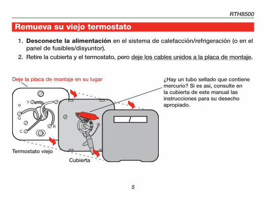
Remueva su viejo termostato
1. Desconecte la alimentación en el sistema de calefacción/refrigeración (o en el panel de fusibles/disyuntor).
2. Retire la cubierta y el termostato, pero deje los cables unidos a la placa de montaje.
¿Hay un tubo sellado que contiene mercurio? Si es así, consulte en la cubierta de este manual las instrucciones para su desecho apropiado.
Termostato viejo
Cubierta
Deje la placa de montaje en su lugar

�
Guía de Instalación
Rotule los cables y retire la vieja placa de montaje
Use un destornillador para desconectar los cables uno a uno. A medida que desco-necte cada cable, péguele alrededor el rótulo con la misma letra que figura en su viejo termostato. (En el paquete de su termostato se incluyen rótulos autoadhesivos.)
Retire la vieja placa de montaje sólo después de haber rotulado todos los cables. Tenga cuidado de no dejar que los cables sueltos caigan en el hueco de la pared.
Envuelva firmemente los rótulos provistos alrededor de cada cable.
¡No permita que los cables caigan en el hueco de la pared!
IGNORE LOS COLORES DE LOS CABLES: Use sólo letras para identificar los tipos de cable.
RTH8500
�
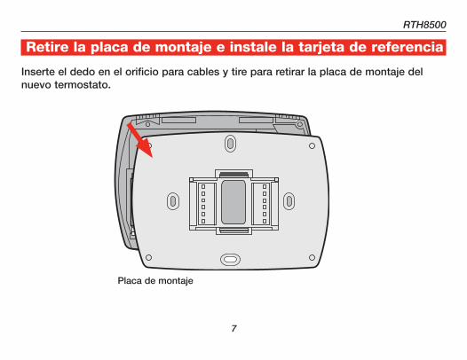
Retire la placa de montaje e instale la tarjeta de referencia
Inserte el dedo en el orificio para cables y tire para retirar la placa de montaje del nuevo termostato.
Placa de montaje
+
+ +
8
Guía de Instalación
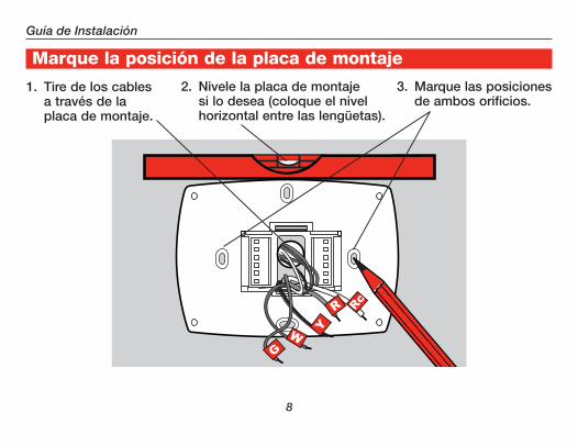
Marque la posición de la placa de montaje
1. Tire de los cables a través de la placa de montaje.
2. Nivele la placa de montaje si lo desea (coloque el nivel horizontal entre las lengüetas).
3. Marque las posiciones de ambos orificios.
RTH8500
�
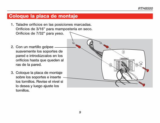
Coloque la placa de montaje
1. Taladre orificios en las posiciones marcadas. Orificios de 3/16” para mampostería en seco. Orificios de 7/32” para yeso.
2. Con un martillo golpee suavemente los soportes de pared e introdúzcalos en los orificios hasta que queden al ras de la pared.
3. Coloque la placa de montaje sobre los soportes e inserte los tornillos. Revise el nivel si lo desea y luego ajuste los tornillos.
�0
Guía de Instalación
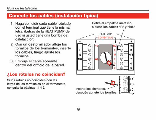
Conecte los cables (instalación típica)
1. Haga coincidir cada cable rotulado con el terminal que tiene la misma letra. (Letras de la HEAT PUMP del uso si usted tiene una bomba de calefacción)
2. Con un destornillador afloje los tornillos de los terminales, inserte los cables, luego ajuste los tornillos.
3. Empuje el cable sobrante dentro del orificio de la pared.
Retire el empalme metálico si tiene los cables “R” y “Rc.”
¿Los rótulos no coinciden?Si los rótulos no coinciden con las letras de los terminales en el termostato, consulte la páginas 11-12. Inserte los alambres,
después apriete los tornillos.
RTH8500
��
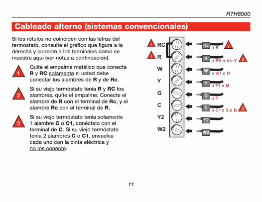
Si los rótulos no coinciden con las letras del termostato, consulte el gráfico que figura a la derecha y conecte a los terminales como se muestra aquí (ver notas a continuación).
Quite el empalme metálico que conecta R y RC solamente si usted debe conectar los alambres de R y de Rc.
Si su viejo termóstato tenía R y RC los alambres, quite el empalme. Conecte el alambre de R con el terminal de Rc, y el alambre Rc con el terminal de R.
Si su viejo termóstato tenía solamente 1 alambre C o C1, conéctelo con el terminal de C. Si su viejo termóstato tenía 2 alambres C o C1, envuelva cada uno con la cinta eléctrica y no los conecte.
Cableado alterno (sistemas convencionales)
RC
R
W
Y
G
C
Y2
W2
Rc
R
W
Y
G
C
Y2
W2
2
3
2
��
Guía de Instalación
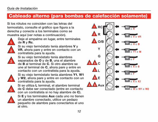
Si los rótulos no coinciden con las letras del termostato, consulte el gráfico que figura a la derecha y conecte a los terminales como se muestra aquí (ver notas a continuación).
Deje el empalme en lugar, entre terminales de R y Rc.Si su viejo termóstato tenía alambres V y VR, ahora pare y entre en contacto con un contratista para la ayuda.Si su viejo termóstato tenía alambres separados de O y de B, una el alambre de B al terminal de C. Si otro alambre se une al terminal de C, ahora pare y entre en contacto con un contratista para la ayuda.Si su viejo termóstato tenía alambres Y1, W1 y W2, ahora pare y entre en contacto con un contratista para la ayuda.Si se utiliza L terminal, el alambre terminal de C debe ser conectado (entre en contacto con un contratista si no hay alambre de C).Si E y los terminales Aux cada uno no tienen un alambre conectado, utilice un pedazo pequeño de alambre para conectarlos el uno al otro.
Cableado alterno (para bombas de calefacción solamente)
2
3
3
4
5
5
6
6
5
6
RTH8500
��
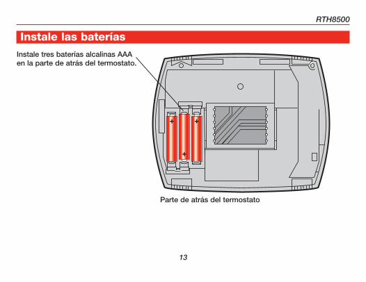
Instale las bateríasInstale tres baterías alcalinas AAA en la parte de atrás del termostato.
Parte de atrás del termostato
��
Guía de Instalación
Retire la lengüeta y arme el termostato
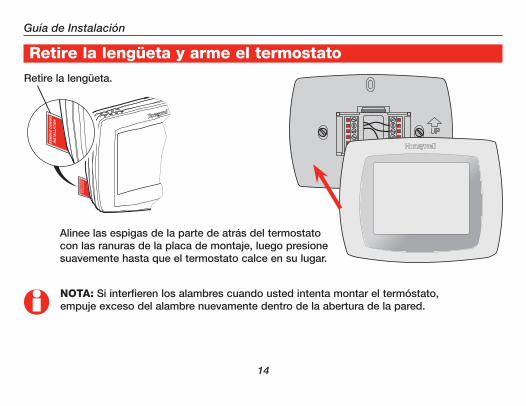
NOTA: Si interfieren los alambres cuando usted intenta montar el termóstato, empuje exceso del alambre nuevamente dentro de la abertura de la pared.
Retire la lengüeta.
Alinee las espigas de la parte de atrás del termostato con las ranuras de la placa de montaje, luego presione suavemente hasta que el termostato calce en su lugar.
RTH8500
�5
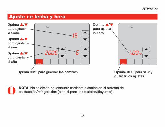
Ajuste de fecha y hora
NOTA: No se olvide de restaurar corriente eléctrica en el sistema de calefacción/refrigeración (o en el panel de fusibles/disyuntor).
Oprima s/t para ajustar la fecha
Oprima s/t para ajustar el mes
Oprima s/t para ajustar el año
Oprima s/t para ajustar la hora
Oprima DONE para guardar los cambios Oprima DONE para salir y guardar los ajustes
DONE
TUE
15
62006
DONE
TUE
6PM1:00
��
Guía de Instalación
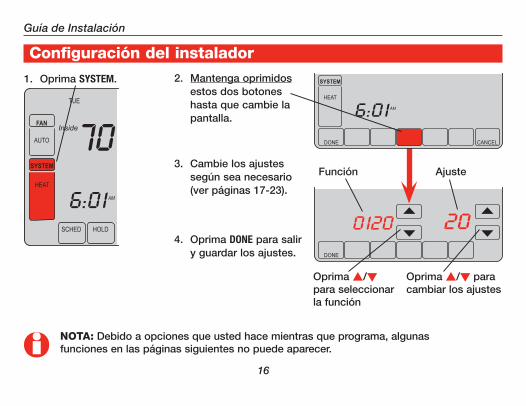
Configuración del instalador
NOTA: Debido a opciones que usted hace mientras que programa, algunas funciones en las páginas siguientes no puede aparecer.
2. Mantenga oprimidos estos dos botones hasta que cambie la pantalla.
1. Oprima SYSTEM.
Oprima s/t para seleccionar la función
Función Ajuste
Oprima s/t para cambiar los ajustes
SCHED HOLD SCREEN MORE
TUE
AM
FollowingSchedule
Inside
Outside
Set To70
6:01
70
43
FAN
AUTO
SYSTEM
HEAT
DONE
TUE
Inside Set To70
0120
70
20
FAN
AUTO
DONE CANCEL
TUE
AM
Inside Set To70
6:01
70FAN
AUTO
SYSTEM
HEAT
3. Cambie los ajustes según sea necesario (ver páginas 17-23).
4. Oprima DONE para salir y guardar los ajustes.

RTH8500
��
Configuración del instalador
Ajuste de año (primeros dos dígitos)Función 0120
Oprima s/t para cambiar los primeros dos dígitos del año:
Opciones: 20 = Año 20xx 21 = Año 21xx
Ajuste de año (segundos dos dígitos)Función 0130
Oprima s/t para cambiar los últimos dos dígitos del año:
Opciones: 01 - 99 (ej., 2001 - 2099)
Ajuste de mesFunción 0140
Oprima s/t para cambiar el mes actual:
Opciones: 01 - 12 (ej., Enero - Diciembre)
Ajuste de fechaFunción 0150
Oprima s/t para cambiar la fecha actual:
Opciones: 01 - 31
�8
Guía de Instalación
Configuración del instalador
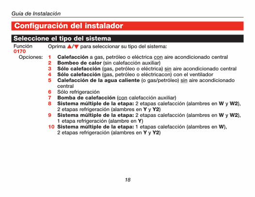
Seleccione el tipo del sistemaFunción 0170
Oprima s/t para seleccionar su tipo del sistema:
Opciones: 1 Calefacción a gas, petróleo o eléctrica con aire acondicionado central2 Bombeo de calor (sin calefacción auxiliar)3 Sólo calefacción (gas, petróleo o eléctrica) sin aire acondicionado central4 Sólo calefacción (gas, petróleo o eléctricacon) con el ventilador5 Calefacción de la agua caliente (o gas/petróleo) sin aire acondicionado
central6 Sólo refrigeración7 Bomba de calefacción (con calefacción auxiliar)8 Sistema múltiple de la etapa: 2 etapas calefacción (alambres en W y W2),
2 etapas refrigeración (alambres en Y y Y2)9 Sistema múltiple de la etapa: 2 etapas calefacción (alambres en W y W2),
1 etapa refrigeración (alambre en Y)10 Sistema múltiple de la etapa: 1 etapas calefacción (alambres en W),
2 etapas refrigeración (alambres en Y y Y2)
RTH8500
��
Configuración del instalador
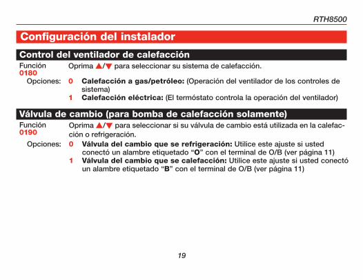
Control del ventilador de calefacciónFunción 0180
Oprima s/t para seleccionar su sistema de calefacción.
Opciones: 0 Calefacción a gas/petróleo: (Operación del ventilador de los controles de sistema)
1 Calefacción eléctrica: (El termóstato controla la operación del ventilador)
Válvula de cambio (para bomba de calefacción solamente)Función 0190
Oprima s/t para seleccionar si su válvula de cambio está utilizada en la calefac-ción o refrigeración.
Opciones: 0 Válvula del cambio que se refrigeración: Utilice este ajuste si usted conectó un alambre etiquetado “O” con el terminal de O/B (ver página 11)
1 Válvula del cambio que se calefacción: Utilice este ajuste si usted conectó un alambre etiquetado “B” con el terminal de O/B (ver página 11)

�0
Guía de Instalación
Configuración del instalador
Frecuencia del ciclo de calefacciónFunción 0240
Oprima s/t para seleccionar su sistema de calefacción.
Opciones: 5 Estufa normal a gas o petróleo: Estufa normal a gas o petróleo que tiene una eficiencia menor al 90%
9 Estufa eléctrica: Use este ajuste si tiene cualquier tipo de sistema de cal-efacción eléctrico
3 Sistema de agua caliente o estufa de alta eficiencia: Sistema de agua caliente o una estufa a gas con una eficiencia mayor al 90%
1 Sistema vapor (gas o petróleo) o sistema gravedad
Calefacción de la emergencia (para bomba de calefacción solamente)Función 0270
Oprima s/t para seleccionar su sistema de calefacción.
Opciones: 9 Estufa eléctrica: Use este ajuste si tiene cualquier tipo de sistema de cal-efacción eléctrico
5 Estufa a gas o petróleo: Estufa normal a gas o petróleo que tiene una eficiencia menor al 90%
3 Sistema de agua caliente o estufa de alta eficiencia: Sistema de agua caliente o una estufa a gas con una eficiencia mayor al 90%
1 Sistema vapor (gas o petróleo) o sistema gravedad
RTH8500
��
Configuración del instalador
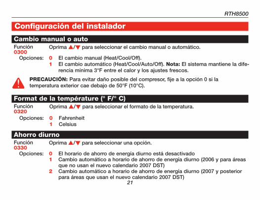
Cambio manual o autoFunción 0300
Oprima s/t para seleccionar el cambio manual o automático.
Opciones: 0 El cambio manual (Heat/Cool/Off).1 El cambio automático (Heat/Cool/Auto/Off). Nota: El sistema mantiene la dife-
rencia mínima 3°F entre el calor y los ajustes frescos.
Format de la température (° F/° C)Función 0320
Oprima s/t para seleccionar el formato de la temperatura.
Opciones: 0 Fahrenheit1 Celsius
Ahorro diurnoFunción 0330
Oprima s/t para seleccionar una opción.
Opciones: 0 El horario de ahorro de energía diurno está desactivado1 Cambio automático a horario de ahorro de energía diurno (2006 y para áreas
que no usan el nuevo calendario 2007 DST)2 Cambio automático a horario de ahorro de energía diurno (2007 y posterior
para áreas que usan el nuevo calendario 2007 DST)
PRECAUCIóN: Para evitar daño posible del compresor, fije a la opción 0 si la temperatura exterior cae debajo de 50°F (10°C).
��
Guía de Instalación
Configuración del instalador
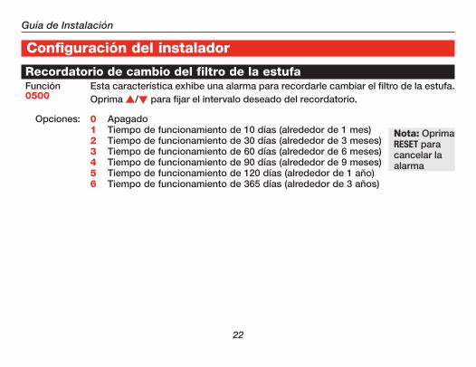
Recordatorio de cambio del filtro de la estufaFunción 0500
Esta característica exhibe una alarma para recordarle cambiar el filtro de la estufa. Oprima s/t para fijar el intervalo deseado del recordatorio.
Opciones: 0 Apagado1 Tiempo de funcionamiento de 10 días (alrededor de 1 mes)2 Tiempo de funcionamiento de 30 días (alrededor de 3 meses)3 Tiempo de funcionamiento de 60 días (alrededor de 6 meses)4 Tiempo de funcionamiento de 90 días (alrededor de 9 meses)5 Tiempo de funcionamiento de 120 días (alrededor de 1 año)6 Tiempo de funcionamiento de 365 días (alrededor de 3 años)
Nota: Oprima RESET para cancelar la alarma

RTH8500
��
Configuración del instalador
Smart Response® Technology (activo o apagado)Función 0530
Oprima s/t para seleccionar o para deselect esta característica (ver el Manual de Uso para más información).
Opciones: 1 Activo0 Apagado
Formato del relojFunción 0640
Oprima s/t para seleccionar el formato del reloj.
Opciones: 12 Reloj 12-hour (3:30 pm)24 Reloj 24-hour (15:30 pm)
��
Guía de Instalación
En caso de dificultades
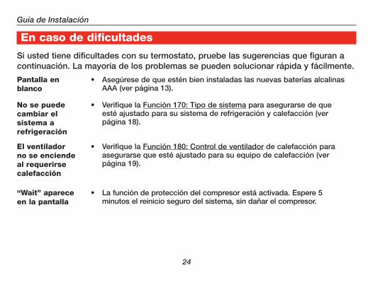
Si usted tiene dificultades con su termostato, pruebe las sugerencias que figuran a continuación. La mayoría de los problemas se pueden solucionar rápida y fácilmente.
Pantalla en blanco
• Asegúrese de que estén bien instaladas las nuevas baterías alcalinas AAA (ver página 13).
No se puede cambiar el sistema a refrigeración
• Verifique la Función 170: Tipo de sistema para asegurarse de que esté ajustado para su sistema de refrigeración y calefacción (ver página 18).
El ventilador no se enciende al requerirse calefacción
• Verifique la Función 180: Control de ventilador de calefacción para asegurarse que esté ajustado para su equipo de calefacción (ver página 19).
“Wait” aparece en la pantalla
• La función de protección del compresor está activada. Espere 5 minutos el reinicio seguro del sistema, sin dañar el compresor.

RTH8500
�5
En caso de dificultadesNo responde el sistema de calefacción o refrigeración
• Oprima SYSTEM para fijar el sistema en Heat. Asegúrese de que la temperatura sea superior a la temperatura interior.
• Oprima SYSTEM para fijar el sistema en Cool. Asegúrese de que la temperatura sea inferior a la temperatura interior.
• Verifique el disyuntor y reinicie si es necesario.• Asegúrese de que esté encendido el interruptor del sistema de
calefacción y refrigeración.• Asegúrese de que esté bien cerrada la puerta de la estufa.• Espere 5 minutos la respuesta del sistema.
El piloto rojo está encendido
• Si el termóstato está en modo del calefacción de la emergencia la luz roja es normal. Demuestra que el termóstato está en modo del calefacción de la emergencia.
• Si el termóstato no está en modo del calefacción de la emergencia, entre en contacto con un contratista cualificado del servicio para la reparación.

��
Guía de Instalación
En caso de dificultadesEl bombeo de calor emite aire frío en modo calefacción o aire caliente en modo refrigeración
• Verifique la Función 190: Válvula de cambio del sistema de bombeo de calor para asegurarse de que esté configurada correctamente para su sistema (ver página 19).
El equipo de calefacción y el de refrigeración funcionan frío al mismo tiempo (o la calefacción no se apaga)
• Verifique la Función 170: Tipo de sistema para asegurarse de que esté ajustado para su sistema de refrigeración y calefacción (ver página 18).
• Agarre y saque el termostato de la placa de montaje. Verifique para asegurarse de que los cables desnudos no se toquen entre sí.
El equipo de calefacción funciona en modo de refrigeración
• Verifique la Función 170: Tipo de sistema para asegurarse de que esté ajustado para su sistema de refrigeración y calefacción (ver página 18).

RTH8500
��
Si necesita asistencia, visite http://yourhome.honeywell.com o llame al número gratuito de atención al cliente de Honeywell al 1-800-468-1502.
Asistencia al cliente
�8
Guía de Instalación
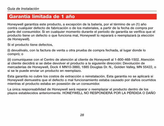
Garantía limitada de 1 añoHoneywell garantiza este producto, a excepción de la batería, por el término de un (1) año contra cualquier defecto de fabricación o de los materiales, a partir de la fecha de compra por parte del consumidor. Si en cualquier momento durante el período de garantía se verifica que el producto tiene un defecto o que funciona mal, Honeywell lo reparará o reemplazará (a elección de Honeywell).
Si el producto tiene defectos,
(i) devuélvalo, con la factura de venta u otra prueba de compra fechada, al lugar donde lo compró; o
(ii) comuníquese con el Centro de atención al cliente de Honeywell al 1-800-468-1502. Atención al cliente decidirá si se debe devolver el producto a la siguiente dirección: Devolución de mercaderías de Honeywell, Dock 4 MN10-3860, 1885 Douglas Dr. N., Golden Valley, MN 55422, o si se le puede enviar un producto en reemplazo.
Esta garantía no cubre los costos de extracción o reinstalación. Esta garantía no se aplicará si Honeywell demuestra que el defecto o mal funcionamiento estaba causado por daños ocurridos mientras el producto estaba en posesión de un consumidor.
La única responsabilidad de Honeywell será reparar o reemplazar el producto dentro de los plazos establecidos anteriormente. HONEYWELL NO RESPONDERÁ POR LA PÉRDIDA O DAÑO

RTH8500
��
Garantía limitada de 1 añoDE NINGÚN TIPO, INCLUIDO EL DAÑO INCIDENTAL O INDIRECTO DERIVADO, DIRECTA O INDIRECTAMENTE, DEL INCUMPLIMIENTO DE LAS GARANTÍAS, EXPRESAS O IMPLICÍTAS, O DE OTRAS FALLAS DE ESTE PRODUCTO. Algunos estados no permiten la exclusión o limitación del daño incidental o indirecto, entonces, esta limitación puede no resultar aplicable a su caso.
LA PRESENTE GARANTÍA ES LA ÚNICA GARANTÍA EXPRESA QUE HONEYWELL PROPORCIONA RESPECTO DE ESTE PRODUCTO. LA DURACIÓN DE LAS GARANTÍAS IMPLÍCITAS, INCLUÍDAS LAS GARANTÍAS DE COMERCIABILIDAD Y APTITUD PARA UN OBJETIVO PARTICULAR, ESTÁ LIMITADA A LA DURACIÓN DE UN AÑO DE LA PRESENTE GARANTÍA.
Algunos estados no permiten las limitaciones sobre la duración del período de una garantía implícita, entonces la limitación anterior puede no resultar aplicable a su caso. Esta garantía le brinda derechos legales específicos, y usted podrá tener otros derechos que varían según el estado.
Si tiene preguntas sobre la presente garantía, sírvase escribir a Honeywell Customer Relations, 1985 Douglas Dr, Golden Valley, MN 55422 o llamar al 1-800-468-1502. En Canadá, escriba a Retail Products ON15-02H, Honeywell Limited/Honeywell Limitée, 35 Dynamic Drive, Toronto, Ontario M1V4Z9.

Honeywell International Inc.
1985 Douglas Drive North
Golden Valley, MN 55422
http://yourhome.honeywell.com
Honeywell Limited-Honeywell Limitée
35 Dynamic Drive
Toronto, Ontario M1V 4Z9
® Marca registrada en EE.UU.Copyright © 2006 Honeywell International Inc.Patente en EE.UU: Nº 6595430 y otras patentes pendientes.69-1902ES—1 M.S. Rev. 03-07
Automation and Control Systems
Impreso en los EE. UU., en papel reciclado que contiene por lo menos un 10% de fibras de papel reciclable.


![WALLPLATES & HOUSINGS...4-Port Wallplate 43080-1S4 43080-2S4 3-Port Wallplate 43080-1S3 2-Port Wallplate 43080-1S2 43080-2S2 1-Port Wallplate 43080-1S1 [D] QUICKPORT STAINLESS STEEL](https://img.dokumen.tips/doc/110x75/5fe8532332ac636a9b7bbb72/wallplates-housings-4-port-wallplate-43080-1s4-43080-2s4-3-port-wallplate.jpg)