Embed Size (px)
Citation preview

Operation
TP-6843 7/15b
r
DC Generator Sets
Models:
6VSG24VDC36VDC48VDC
Controller:
VSC
Engine exhaust from this product contains chemicalsknown to the State of California to cause cancer, birthdefects, or other reproductive harm.
California Proposition 65
WARNING!
Product Identification Information
Product identification numbers determine serviceparts. Record the product identification numbers inthe spaces below immediately after unpacking theproducts so that the numbers are readily available forfuture reference. Record field-installed kit numbersafter installing the kits.
Generator Set Identification Numbers
Record the product identification numbers from thegenerator set nameplate(s).
Model Designation ___________________________
Specification Number _________________________
Serial Number ______________________________
Controller Identification
Record the controller description from the generatorset operation manual, spec sheet, or sales invoice.
Controller Description _________________________
Engine Identification
Record the product identification information from theengine nameplate.
Manufacturer________________________________
Model Designation ___________________________
Serial Number _______________________________
Accessory Number Accessory Description

TP-6843 7/15 Table of Contents 3
Figure 1-1
Table of Contents
Product Identification Information . . . . . . . . . . . . . . . . . . . . . . . . . . . . . . . . . . . . . . . . . . . . . . . 2
Safety Precautions and Instructions. . . . . . . . . . . . . . . . . . . . . . . . . . . . . . . . . . . . . . . . . . . . . . 5
Introduction . . . . . . . . . . . . . . . . . . . . . . . . . . . . . . . . . . . . . . . . . . . . . . . . . . . . . . . . . . . . . . . . . . 9
Service Assistance . . . . . . . . . . . . . . . . . . . . . . . . . . . . . . . . . . . . . . . . . . . . . . . . . . . . . . . . . . . 11
Section 1 Descriptions and Service Views . . . . . . . . . . . . . . . . . . . . . . . . . . . . . . . . . . . . . . 131.1 Introduction . . . . . . . . . . . . . . . . . . . . . . . . . . . . . . . . . . . . . . . . . . . . . . . 131.2 Engine . . . . . . . . . . . . . . . . . . . . . . . . . . . . . . . . . . . . . . . . . . . . . . . . . . . 131.3 Generator Set Enclosure . . . . . . . . . . . . . . . . . . . . . . . . . . . . . . . . . . . . . 131.4 Alternator . . . . . . . . . . . . . . . . . . . . . . . . . . . . . . . . . . . . . . . . . . . . . . . . . 131.5 Controller . . . . . . . . . . . . . . . . . . . . . . . . . . . . . . . . . . . . . . . . . . . . . . . . . 13
1.5.1 VSC Controller Features . . . . . . . . . . . . . . . . . . . . . . . . . . . . . . 131.6 Accessories . . . . . . . . . . . . . . . . . . . . . . . . . . . . . . . . . . . . . . . . . . . . . . . 14
1.6.1 Carburetor Heater. . . . . . . . . . . . . . . . . . . . . . . . . . . . . . . . . . . . 141.6.2 OnCue® Generator Management System . . . . . . . . . . . . . . . . . 141.6.3 Programmable Interface Module (PIM) . . . . . . . . . . . . . . . . . . . 141.6.4 Communications Kit . . . . . . . . . . . . . . . . . . . . . . . . . . . . . . . . . . 14
1.7 Service Views . . . . . . . . . . . . . . . . . . . . . . . . . . . . . . . . . . . . . . . . . . . . . 15
Section 2 Generator Set Operation . . . . . . . . . . . . . . . . . . . . . . . . . . . . . . . . . . . . . . . . . . . . 172.1 Theory of Operation . . . . . . . . . . . . . . . . . . . . . . . . . . . . . . . . . . . . . . . . 172.2 Prestart Checklist . . . . . . . . . . . . . . . . . . . . . . . . . . . . . . . . . . . . . . . . . . 172.3 Exercising the Generator Set . . . . . . . . . . . . . . . . . . . . . . . . . . . . . . . . . 182.4 Generator Set Operation . . . . . . . . . . . . . . . . . . . . . . . . . . . . . . . . . . . . . 18
2.4.1 Local Starting and Stopping . . . . . . . . . . . . . . . . . . . . . . . . . . . . 182.4.2 Remote Starting and Stopping . . . . . . . . . . . . . . . . . . . . . . . . . . 182.4.3 Engine Start Crank Cycle . . . . . . . . . . . . . . . . . . . . . . . . . . . . . . 182.4.4 Engine Cooldown . . . . . . . . . . . . . . . . . . . . . . . . . . . . . . . . . . . . 182.4.5 Automatic Operation. . . . . . . . . . . . . . . . . . . . . . . . . . . . . . . . . . 18
2.5 Exercise. . . . . . . . . . . . . . . . . . . . . . . . . . . . . . . . . . . . . . . . . . . . . . . . . . 192.6 Faults. . . . . . . . . . . . . . . . . . . . . . . . . . . . . . . . . . . . . . . . . . . . . . . . . . . . 19
2.6.1 Warnings . . . . . . . . . . . . . . . . . . . . . . . . . . . . . . . . . . . . . . . . . . 192.6.2 Shutdowns . . . . . . . . . . . . . . . . . . . . . . . . . . . . . . . . . . . . . . . . . 192.6.3 Resetting the Controller After a Fault Shutdown . . . . . . . . . . . . 20
Section 3 VSC Controller Operation. . . . . . . . . . . . . . . . . . . . . . . . . . . . . . . . . . . . . . . . . . . . 233.1 VSC Generator Set Controller . . . . . . . . . . . . . . . . . . . . . . . . . . . . . . . . . 233.2 Control and Indicators . . . . . . . . . . . . . . . . . . . . . . . . . . . . . . . . . . . . . . . 23
3.2.1 Controller Keypad. . . . . . . . . . . . . . . . . . . . . . . . . . . . . . . . . . . . 243.2.2 LED Indicators . . . . . . . . . . . . . . . . . . . . . . . . . . . . . . . . . . . . . . 243.2.3 LCD Display. . . . . . . . . . . . . . . . . . . . . . . . . . . . . . . . . . . . . . . . 25
3.3 Controller Power . . . . . . . . . . . . . . . . . . . . . . . . . . . . . . . . . . . . . . . . . . . 263.4 Battery Charging . . . . . . . . . . . . . . . . . . . . . . . . . . . . . . . . . . . . . . . . . . . 263.5 Changing Settings . . . . . . . . . . . . . . . . . . . . . . . . . . . . . . . . . . . . . . . . . . 26
3.5.1 Procedure to Change Settings . . . . . . . . . . . . . . . . . . . . . . . . . . 263.6 Setting the Exerciser . . . . . . . . . . . . . . . . . . . . . . . . . . . . . . . . . . . . . . . . 28
3.6.1 Setting the Exerciser at Controller Power-up . . . . . . . . . . . . . . . 283.6.2 Changing the Exercise Settings . . . . . . . . . . . . . . . . . . . . . . . . . 28
3.7 VSC Controller Menus. . . . . . . . . . . . . . . . . . . . . . . . . . . . . . . . . . . . . . . 303.8 Main Menu. . . . . . . . . . . . . . . . . . . . . . . . . . . . . . . . . . . . . . . . . . . . . . . . 303.9 Overview Menu . . . . . . . . . . . . . . . . . . . . . . . . . . . . . . . . . . . . . . . . . . . . 313.10 Engine Metering Menu . . . . . . . . . . . . . . . . . . . . . . . . . . . . . . . . . . . . . . 313.11 Generator Metering Menu . . . . . . . . . . . . . . . . . . . . . . . . . . . . . . . . . . . . 32
3.11.1 Calibration . . . . . . . . . . . . . . . . . . . . . . . . . . . . . . . . . . . . . . . . . 323.12 Generator Set Information Menu. . . . . . . . . . . . . . . . . . . . . . . . . . . . . . . 333.13 Genset Run Time Menu . . . . . . . . . . . . . . . . . . . . . . . . . . . . . . . . . . . . . 333.14 Genset System Menu . . . . . . . . . . . . . . . . . . . . . . . . . . . . . . . . . . . . . . . 34

Table of Contents
4 Table of Contents TP-6843 7/15
3.14.1 System Parameters for Battery Bank Charging . . . . . . . . . . . . . 343.14.2 Setting the Exerciser . . . . . . . . . . . . . . . . . . . . . . . . . . . . . . . . . 363.14.3 Adjusting the Display Contrast . . . . . . . . . . . . . . . . . . . . . . . . . . 36
3.15 Date and Time Menu. . . . . . . . . . . . . . . . . . . . . . . . . . . . . . . . . . . . . . . . 373.16 Networking Information Menus . . . . . . . . . . . . . . . . . . . . . . . . . . . . . . . . 37
3.16.1 Networking Status Submenu . . . . . . . . . . . . . . . . . . . . . . . . . . . 383.16.2 Networking Configuration Submenu (OnCue® Password) . . . . 393.16.3 RBUS Information . . . . . . . . . . . . . . . . . . . . . . . . . . . . . . . . . . . 403.16.4 Remote Devices Submenu . . . . . . . . . . . . . . . . . . . . . . . . . . . . 41
3.17 Programmable Interface Module (PIM) Status Menu . . . . . . . . . . . . . . . 423.18 Event Log . . . . . . . . . . . . . . . . . . . . . . . . . . . . . . . . . . . . . . . . . . . . . . . . 43
3.18.1 Procedure to View Event History . . . . . . . . . . . . . . . . . . . . . . . . 43
Section 4 Scheduled Maintenance . . . . . . . . . . . . . . . . . . . . . . . . . . . . . . . . . . . . . . . . . . . . . 454.1 Scheduled Maintenance . . . . . . . . . . . . . . . . . . . . . . . . . . . . . . . . . . . . . 45
4.1.1 Service Schedule, 6VSG Models . . . . . . . . . . . . . . . . . . . . . . . 464.2 Lubrication System . . . . . . . . . . . . . . . . . . . . . . . . . . . . . . . . . . . . . . . . . 47
4.2.1 Low Oil Pressure Shutdown . . . . . . . . . . . . . . . . . . . . . . . . . . . . 474.2.2 Oil Check . . . . . . . . . . . . . . . . . . . . . . . . . . . . . . . . . . . . . . . . . . 474.2.3 Engine Oil Recommendation . . . . . . . . . . . . . . . . . . . . . . . . . . . 474.2.4 Oil Change Procedure . . . . . . . . . . . . . . . . . . . . . . . . . . . . . . . . 474.2.5 Resetting the Maintenance Timer. . . . . . . . . . . . . . . . . . . . . . . . 48
4.3 Spark Plugs . . . . . . . . . . . . . . . . . . . . . . . . . . . . . . . . . . . . . . . . . . . . . . . 484.4 Air Cleaner Service . . . . . . . . . . . . . . . . . . . . . . . . . . . . . . . . . . . . . . . . . 494.5 Cooling System . . . . . . . . . . . . . . . . . . . . . . . . . . . . . . . . . . . . . . . . . . . . 504.6 Exhaust System . . . . . . . . . . . . . . . . . . . . . . . . . . . . . . . . . . . . . . . . . . . 504.7 Engine Starting Battery . . . . . . . . . . . . . . . . . . . . . . . . . . . . . . . . . . . . . . 504.8 Storage Procedure . . . . . . . . . . . . . . . . . . . . . . . . . . . . . . . . . . . . . . . . . 51
4.8.1 Lubricating System. . . . . . . . . . . . . . . . . . . . . . . . . . . . . . . . . . . 514.8.2 Fuel System . . . . . . . . . . . . . . . . . . . . . . . . . . . . . . . . . . . . . . . . 514.8.3 Cylinder Lubrication . . . . . . . . . . . . . . . . . . . . . . . . . . . . . . . . . . 514.8.4 Exterior Preparation . . . . . . . . . . . . . . . . . . . . . . . . . . . . . . . . . . 514.8.5 Battery . . . . . . . . . . . . . . . . . . . . . . . . . . . . . . . . . . . . . . . . . . . . 52
Section 5 Troubleshooting . . . . . . . . . . . . . . . . . . . . . . . . . . . . . . . . . . . . . . . . . . . . . . . . . . . 535.1 Introduction . . . . . . . . . . . . . . . . . . . . . . . . . . . . . . . . . . . . . . . . . . . . . . . 535.2 Fault Messages . . . . . . . . . . . . . . . . . . . . . . . . . . . . . . . . . . . . . . . . . . . . 535.3 Circuit Protection . . . . . . . . . . . . . . . . . . . . . . . . . . . . . . . . . . . . . . . . . . . 53
5.3.1 Controller Internal Circuit Protection. . . . . . . . . . . . . . . . . . . . . . 535.3.2 Line Circuit Breaker . . . . . . . . . . . . . . . . . . . . . . . . . . . . . . . . . . 53
5.4 Controller Service Access . . . . . . . . . . . . . . . . . . . . . . . . . . . . . . . . . . . . 535.5 Troubleshooting. . . . . . . . . . . . . . . . . . . . . . . . . . . . . . . . . . . . . . . . . . . . 54
Appendix A Abbreviations . . . . . . . . . . . . . . . . . . . . . . . . . . . . . . . . . . . . . . . . . . . . . . . . . . . . 55

TP-6843 7/15 Safety Precautions and Instructions 5
Safety Precautions and Instructions
IMPORTANT SAFETY INSTRUCTIONSElectro-mechanical equipment, includinggenerator sets, transfer switches,switchgear, and accessories, can causebodily harm and pose life-threateningdanger when improperly installed,operated, or maintained. To preventaccidents be aware of potential dangersand act safely. Read and follow all safetyprecautions and instructions. SAVETHESE INSTRUCTIONS.
This manual has several types ofsafety precautions and instructions:Danger, Warning, Caution, and Notice.
Danger indicates the presence of ahazard that will cause severepersonal injury, death, orsubstantial property damage.
Warning indicates the presence of ahazard that can cause severe personalinjury, death, or substantial propertydamage.
Caution indicates the presence of ahazard that will or can cause minorpersonaI injury or property damage.
Notice communicates installation,operation, or maintenance informationthat is safety related but not hazardrelated.
Safety decals affixed to the equipmentin prominent places alert the operatoror service technician to potentialhazards and explain how to act safely.The decals are shown throughout thispublication to improve operatorrecognition. Replace missing ordamaged decals.
Accidental Starting
Disabling the generator set.Accidental starting can causesevere injury or death. Beforeworking on the generator set orequipment connected to the set,disable the generator set as follows:(1) Press the generator setOFF/RESET button to shut down thegenerator set. (2) Disconnect thepower to the battery charger, ifequipped. (3) Remove the batterycables, negative (–) lead first.Reconnect the negative (–) lead lastwhen reconnecting the battery. Followthese precautions to prevent thestarting of the generator set by theremote start/stop switch.
Battery
Battery electrolyte is a dilutedsulfuric acid. Battery acid cancause severe injury or death.Battery acid can cause blindness andburn skin. Always wear splashproofsafety goggles, rubber gloves, andboots when servicing the battery. Donot open a sealed battery or mutilatethe battery case. If battery acidsplashes in the eyes or on the skin,immediately flush the affected area for15 minutes with large quantities ofclean water. Seek immediate medicalaid in the case of eye contact. Neveradd acid to a battery after placing thebattery in service, as this may result inhazardous spattering of battery acid.
Battery acid cleanup. Battery acidcan cause severe injury or death.Battery acid is electrically conductiveand corrosive. Add 500 g (1 lb.) ofbicarbonate of soda (baking soda) to acontainer with 4 L (1 gal.) of water andmix the neutralizing solution. Pour theneutralizing solution on the spilledbattery acid and continue to add theneutralizing solution to the spilledbattery acid until all evidence of achemical reaction (foaming) hasceased. Flush the resulting liquid withwater and dry the area.
DANGER!
WARNING!
CAUTION!
NOTICE
WARNING!
Accidental starting.Can cause severe injury or death.
Disconnect the battery cables beforeworking on the generator set.Remove the negative (–) lead firstwhen disconnecting the battery.Reconnect the negative (–) lead lastwhen reconnecting the battery.
WARNING!
Sulfuric acid in batteries.Can cause severe injury or death.
Wear protective goggles andclothing. Battery acid may causeblindness and burn skin.
WARNING!
Explosion.Can cause severe injury or death.Relays in the battery chargercause arcs or sparks.
Locate the battery in awell-ventilated area. Isolate thebattery charger from explosivefumes.

6 Safety Precautions and Instructions TP-6843 7/15
Battery gases. Explosion cancause severe injury or death.Battery gases can cause an explosion.Do not smoke or permit flames orsparks to occur near a battery at anytime, particularly when it is charging.Do not dispose of a battery in a fire.To prevent burns and sparks thatcould cause an explosion, avoidtouching the battery terminals withtools or other metal objects. Removeall jewelry before servicing theequipment. Discharge static electricityfrom your body before touchingbatteries by first touching a groundedmetal surface away from the battery.To avoid sparks, do not disturb thebattery charger connections while thebattery is charging. Always turn thebattery charger off beforedisconnecting the battery connections.Ventilate the compartments containingbatteries to prevent accumulation ofexplosive gases.
Battery short circuits. Explosioncan cause severe injury or death.Short circuits can cause bodily injuryand/or equipment damage.Disconnect the battery beforegenerator set installation ormaintenance. Remove all jewelrybefore servicing the equipment. Usetools with insulated handles. Removethe negative (–) lead first whendisconnecting the battery. Reconnectthe negative (–) lead last whenreconnecting the battery. Neverconnect the negative (–) battery cableto the positive (+) connection terminalof the starter solenoid. Do not test thebattery condition by shorting theterminals together.
Engine Backfire/Flash Fire
Servicing the air cleaner. A suddenbackfire can cause severe injury ordeath. Do not operate the generatorset with the air cleaner removed.
Servicing the fuel system. A flashfire can cause severe injury ordeath. Do not smoke or permit flamesor sparks near the carburetor, fuel line,fuel filter, fuel pump, or other potentialsources of spilled fuels or fuel vapors.Catch fuels in an approved containerwhen removing the fuel line orcarburetor.
Combustible materials. A fire cancause severe injury or death.Generator set engine fuels and fuelvapors are flammable and explosive.Handle these materials carefully tominimize the risk of fire or explosion.Equip the compartment or nearby areawith a fully charged fire extinguisher.Select a fire extinguisher rated ABC orBC for electrical fires or asrecommended by the local fire code oran authorized agency. Train allpersonnel on fire extinguisheroperation and fire preventionprocedures.
Exhaust System
Generator set operation. Carbonmonoxide can cause severenausea, fainting, or death. Carbonmonoxide is an odorless, colorless,tasteless, nonirritating gas that cancause death if inhaled for even a shorttime. Avoid breathing exhaust fumeswhen working on or near the generatorset. Never operate the generator setinside a building. Never operate thegenerator set where exhaust gascould seep inside or be drawn into apotentially occupied building throughwindows, air intake vents, or otheropenings.
Carbon monoxide detectors.Carbon monoxide can cause severenausea, fainting, or death. Installcarbon monoxide detectors on eachlevel of any building adjacent to thegenerator set. Locate the detectors toadequately warn the building’soccupants of the presence of carbonmonoxide. Keep the detectorsoperational at all times. Periodicallytest and replace the carbon monoxidedetectors according to themanufacturer’s instructions.
Carbon monoxide symptoms.Carbon monoxide can cause severenausea, fainting, or death. Carbonmonoxide is a poisonous gas presentin exhaust gases. Carbon monoxideis an odorless, colorless, tasteless,nonirritating gas that can cause deathif inhaled for even a short time.Carbon monoxide poisoningsymptoms include but are not limitedto the following:
• Light-headedness, dizziness
• Physical fatigue, weakness in joints and muscles
• Sleepiness, mental fatigue, inability to concentrate or speak clearly, blurred vision
• Stomachache, vomiting, nausea
If experiencing any of these symptomsand carbon monoxide poisoning ispossible, seek fresh air immediatelyand remain active. Do not sit, liedown, or fall asleep. Alert others tothe possibility of carbon monoxidepoisoning. Seek medical attention ifthe condition of affected persons doesnot improve within minutes ofbreathing fresh air.
WARNING!
Risk of fire.Can cause severe injury or death.
Do not smoke or permit flames orsparks near fuels or the fuel system.
WARNING!
Carbon monoxide.Can cause severe nausea,fainting, or death.
The exhaust system must beleakproof and routinely inspected.
TP-6843 7/15 Safety Precautions and Instructions 7
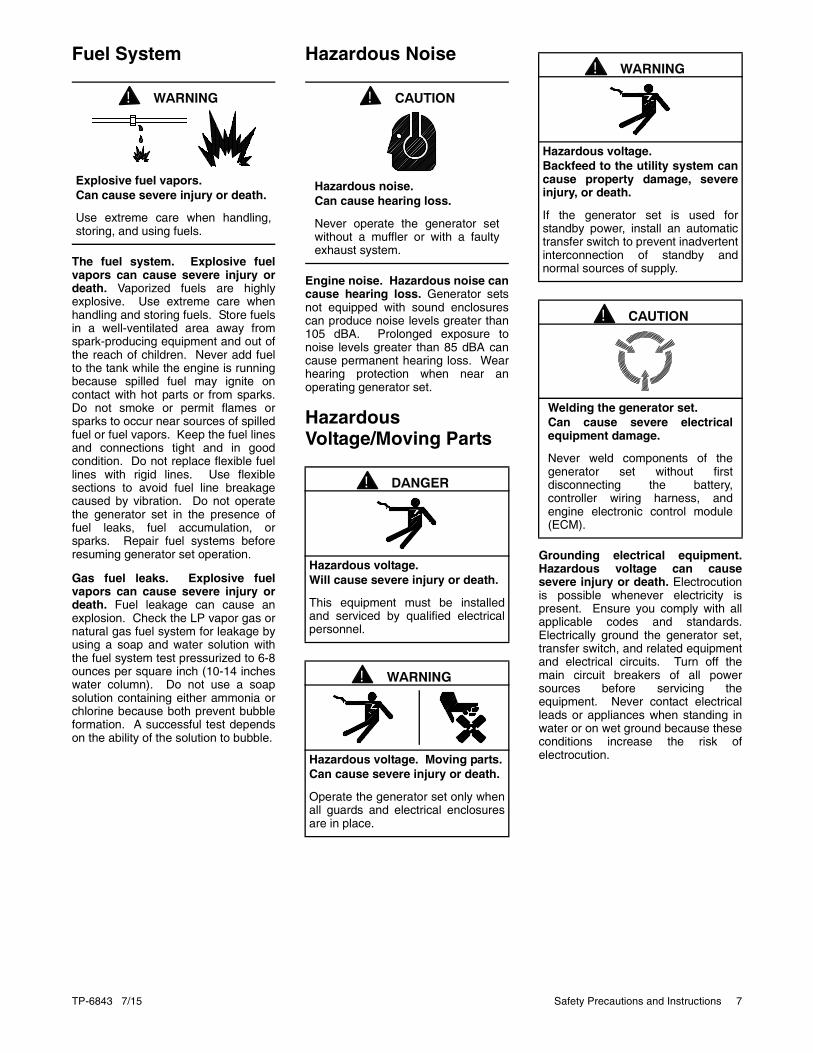
Fuel System
The fuel system. Explosive fuelvapors can cause severe injury ordeath. Vaporized fuels are highlyexplosive. Use extreme care whenhandling and storing fuels. Store fuelsin a well-ventilated area away fromspark-producing equipment and out ofthe reach of children. Never add fuelto the tank while the engine is runningbecause spilled fuel may ignite oncontact with hot parts or from sparks.Do not smoke or permit flames orsparks to occur near sources of spilledfuel or fuel vapors. Keep the fuel linesand connections tight and in goodcondition. Do not replace flexible fuellines with rigid lines. Use flexiblesections to avoid fuel line breakagecaused by vibration. Do not operatethe generator set in the presence offuel leaks, fuel accumulation, orsparks. Repair fuel systems beforeresuming generator set operation.
Gas fuel leaks. Explosive fuelvapors can cause severe injury ordeath. Fuel leakage can cause anexplosion. Check the LP vapor gas ornatural gas fuel system for leakage byusing a soap and water solution withthe fuel system test pressurized to 6-8ounces per square inch (10-14 incheswater column). Do not use a soapsolution containing either ammonia orchlorine because both prevent bubbleformation. A successful test dependson the ability of the solution to bubble.
Hazardous Noise
Engine noise. Hazardous noise cancause hearing loss. Generator setsnot equipped with sound enclosurescan produce noise levels greater than105 dBA. Prolonged exposure tonoise levels greater than 85 dBA cancause permanent hearing loss. Wearhearing protection when near anoperating generator set.
Hazardous Voltage/Moving Parts
Grounding electrical equipment.Hazardous voltage can causesevere injury or death. Electrocutionis possible whenever electricity ispresent. Ensure you comply with allapplicable codes and standards.Electrically ground the generator set,transfer switch, and related equipmentand electrical circuits. Turn off themain circuit breakers of all powersources before servicing theequipment. Never contact electricalleads or appliances when standing inwater or on wet ground because theseconditions increase the risk ofelectrocution.
WARNING!
Explosive fuel vapors.Can cause severe injury or death.
Use extreme care when handling,storing, and using fuels.
CAUTION!
Hazardous noise.Can cause hearing loss.
Never operate the generator setwithout a muffler or with a faultyexhaust system.
DANGER!
Hazardous voltage.Will cause severe injury or death.
This equipment must be installedand serviced by qualified electricalpersonnel.
WARNING!
Hazardous voltage. Moving parts.Can cause severe injury or death.
Operate the generator set only whenall guards and electrical enclosuresare in place.
WARNING!
Hazardous voltage.Backfeed to the utility system cancause property damage, severeinjury, or death.
If the generator set is used forstandby power, install an automatictransfer switch to prevent inadvertentinterconnection of standby andnormal sources of supply.
CAUTION!
Welding the generator set.Can cause severe electricalequipment damage.
Never weld components of thegenerator set without firstdisconnecting the battery,controller wiring harness, andengine electronic control module(ECM).

8 Safety Precautions and Instructions TP-6843 7/15
Welding on the generator set. Cancause severe electrical equipmentdamage. Before welding on thegenerator set perform the followingsteps: (1) Remove the battery cables,negative (–) lead first. (2) Disconnectall engine electronic control module(ECM) connectors. (3) Disconnect allgenerator set controller and voltageregulator circuit board connectors. (4)Disconnect the engine battery-charging alternator connections. (5)Attach the weld ground connectionclose to the weld location.
Connecting the battery and thebattery charger. Hazardous voltagecan cause severe injury or death.Reconnect the battery correctly,positive to positive and negative tonegative, to avoid electrical shock anddamage to the battery charger andbattery(ies). Have a qualifiedelectrician install the battery(ies).
Short circuits. Hazardousvoltage/current can cause severeinjury or death. Short circuits cancause bodily injury and/or equipmentdamage. Do not contact electricalconnections with tools or jewelry whilemaking adjustments or repairs.Remove all jewelry before servicingthe equipment.
Heavy Equipment
Hot Parts
Servicing the exhaust system. Hotparts can cause severe injury ordeath. Do not touch hot engine parts.The engine and exhaust systemcomponents become extremely hotduring operation.
Servicing the engine heater. Hotparts can cause minor personalinjury or property damage. Installthe heater before connecting it topower. Operating the heater beforeinstallation can cause burns andcomponent damage. Disconnectpower to the heater and allow it to coolbefore servicing the heater or nearbyparts.
WARNING!
Unbalanced weight.Improper lifting can cause severeinjury or death and equipmentdamage.
Do not use lifting eyes.Lift the generator set using liftingbars inserted through the lifting holeson the skid.
WARNING!
Hot engine and exhaust system.Can cause severe injury or death.
Do not work on the generator setuntil it cools.

TP-6843 7/15 Introduction 9
Introduction
This manual provides operation and maintenanceinstructions for the DC (direct current) variable speedmodel 6VSG generator sets equipped with Kohler VSCgenerator set controllers.
This generator set is approved for use in stationaryapplications in locations served by a public utility,photovoltaic cells, wind turbines or any combination ofpower sources tied to a battery bank. Have thegenerator set installed by an authorizeddistributor/dealer or service technician. Refer toInstallation Manual, for installation instructions.
Information in this publication represents dataavailable at the time of print. Kohler Co. reserves theright to change this publication and the productsrepresented without notice and without any obligationor liability whatsoever.
Read this manual and carefully follow all proceduresand safety precautions to ensure proper equipmentoperation and to avoid bodily injury. Read and followthe Safety Precautions and Instructions section at thebeginning of this manual. Keep this manual with theequipment for future reference.
The equipment service requirements are veryimportant to safe and efficient operation. Inspect theparts often and perform required service at theprescribed intervals. Obtain service from anauthorized service distributor/dealer to keepequipment in top condition.
Figure 1
Figure 1 6VSG Generator Set
List of Related Literature
Figure 2 identifies related literature available for thegenerator sets covered in this manual. Only trainedand qualified personnel should install or service thegenerator set.
Figure 2
Figure 2 Related Literature
Literature Type Part Number
Installation Manual, Model 6VSG Generator Set TP-6842
Service Manual, 6VSG Generator Set TP-6844
Operation Manual, OnCue® Software TP-6796
Operation Manual, SiteTech™ Software TP-6701
Installation Instructions, Programmable Interface Module (PIM) TT-1584
Parts Catalog, Model 6VSG TP-6845

10 Introduction TP-6843 7/15
Nameplate
The following illustration shows a typical generator setnameplate. Copy the model, serial, and specificationnumbers from the nameplate into the spaces providedin the product information section on the inside frontcover of this manual. See the service views inSection 1.7 for the nameplate location.
Figure 3
Figure 3 Typical Nameplate
Emission Information
The Kohler Model CH740 engine used on the 6VSGgenerator set is certified to operate using natural gasor LPG fuel.
The Emission Compliance Period referred to on theEmission Control or Air Index label indicates thenumber of operating hours for which the engine hasbeen shown to meet CARB or EPA emissionrequirements. Figure 4 provides the enginecompliance period (in hours) associated with thecategory descriptor, which may be found on thecertification label.
Figure 4
Figure 4 Emission Compliance Period
Refer to the certification label for engine displacement.The exhaust emission control system for the CH740engines (6VSG) is EM for U.S. EPA, California, andEurope. See Figure 1-2 for engine certification labellocation.
GM12070
Emission Compliance Period
EPA Category C 250 hours
Category B 500 hours
Category A 1000 hours
CARB Moderate 125 hours
Intermediate 250 hours
Extended 500 hours
TP-6843 7/15 Service Assistance 11
Service Assistance
For professional advice on generator set powerrequirements and conscientious service, pleasecontact your nearest Kohler distributor or dealer.
• Consult the Yellow Pages under the headingGenerators—Electric.
• Visit the Kohler Power Systems website atKOHLERPower.com.
• Look at the labels and decals on your Kohlerproduct or review the appropriate literature ordocuments included with the product.
• Call toll free in the US and Canada 1-800-544-2444.
• Outside the US and Canada, call the nearestregional office.
Headquarters Europe, Middle East, Africa (EMEA)
Kohler Power Systems Netherlands B.V.Kristallaan 14761 ZC ZevenbergenThe Netherlands
Phone: (31) 168 331630
Fax: (31) 168 331631
Asia Pacific
Power Systems Asia Pacific Regional OfficeSingapore, Republic of Singapore
Phone: (65) 6264-6422
Fax: (65) 6264-6455
China
North China Regional Office, Beijing
Phone: (86) 10 6518 7950(86) 10 6518 7951(86) 10 6518 7952
Fax: (86) 10 6518 7955
East China Regional Office, Shanghai
Phone: (86) 21 6288 0500
Fax: (86) 21 6288 0550
India, Bangladesh, Sri Lanka
India Regional OfficeBangalore, India
Phone: (91) 80 3366208(91) 80 3366231
Fax: (91) 80 3315972
Japan, Korea
North Asia Regional OfficeTokyo, Japan
Phone: (813) 3440-4515
Fax: (813) 3440-2727
Latin America
Latin America Regional OfficeLakeland, Florida, USA
Phone: (863) 619-7568
Fax: (863) 701-7131

12 Service Assistance TP-6843 7/15
Notes
TP-6843 7/15 Section 1 Descriptions and Service Views 13
Section 1 Descriptions and Service Views
1.1 Introduction
The generator set specification sheets provide specificgenerator and engine information. Refer to the specsheet for data not supplied in this manual. Consult thegenerator set service manual, engine operationmanual, and engine service manual for additionalspecifications. Obtain copies of the latest spec sheets,manuals, diagrams, and drawings from your localdistributor/dealer.
1.2 Engine
The generator set has a four-cycle, twin cylinder,air-cooled Kohler engine. The engine operates oncleanburning natural gas or LPG fuel. Enginefeatures include:
• Efficient overhead valve design and full pressurelubrication for maximum power, torque, andreliability under all operating conditions.
• Dependable, maintenance-free electronic ignition.
• Precision-formulated cast iron construction of partssubjected to the most wear and tear.
• Field-convertible multi-fuel systems that allow fuelchangeover from natural gas to LPG (and viceversa) while maintaining CARB emissioncertification.
• The variable-speed engine runs at 2300 rpm at noload and 2900 rpm when supplying full load.
1.3 Generator Set Enclosure
The generator set is housed in a steel enclosure withPower Armor powder coat paint. The enclosure has ahinged, locking door that allows easy access to thegenerator set controller when required, but lockssecurely to prevent unauthorized access.
To open the door, insert the tool provided with theenclosure and turn counterclockwise 1/2 turn.
Be sure to close and lock the enclosure, and keep thetool in a secure location.
1.4 AlternatorThe 6VSG is a direct current (DC) output machine. Itutilizes a 24-pole permanent magnet construction tocreate high frequency three-phase alternating currentwhich is rectified to produce low-ripple DC output.
1.5 Controller
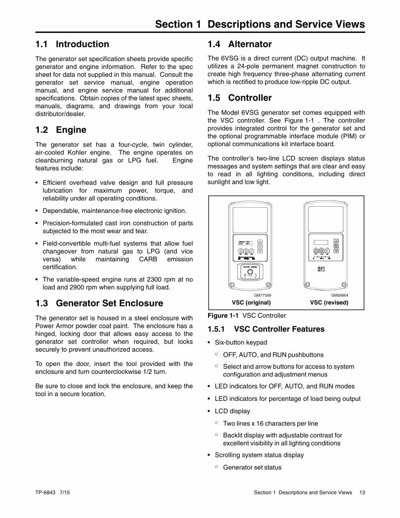
The Model 6VSG generator set comes equipped withthe VSC controller. See Figure 1-1 . The controllerprovides integrated control for the generator set andthe optional programmable interface module (PIM) oroptional communications kit interface board.
The controller’s two-line LCD screen displays statusmessages and system settings that are clear and easyto read in all lighting conditions, including directsunlight and low light.
Figure 1-1
Figure 1-1 VSC Controller
1.5.1 VSC Controller Features
• Six-button keypad
◦ OFF, AUTO, and RUN pushbuttons
◦ Select and arrow buttons for access to system configuration and adjustment menus
• LED indicators for OFF, AUTO, and RUN modes
• LED indicators for percentage of load being output
• LCD display
◦ Two lines x 16 characters per line
◦ Backlit display with adjustable contrast for excellent visibility in all lighting conditions
• Scrolling system status display
◦ Generator set status
GM89864GM77569
VSC (original) VSC (revised)
14 Section 1 Descriptions and Service Views TP-6843 7/15
◦ Voltage and percent load
◦ Engine temperature
◦ Oil pressure
◦ Battery voltage
◦ Engine runtime hours
• Date and time displays
• Smart engine cooldown senses engine temperature
• Digital voltage regulation: ±1.0% RMS no-load tofull-load
• Automatic start with programmed cranking cycle
• Programmable exerciser can be set to startautomatically on any future day and time, and runevery week or every two weeks
• Three exercise modes
• Front-access mini USB connector for SiteTech™
connection
• Integral Ethernet connector for Kohler® OnCue®
• Built-in 2.5 amp battery charger
• Remote two-wire start/stop capability
• Diagnostic messages
◦ Displays diagnostic messages for the engine, generator, and programmable interface module (PIM)
◦ Over 70 diagnostic messages can be displayed
• Maintenance reminders
• System settings
◦ System voltage and percent load
◦ Voltage adjustment
◦ Measurement system, English or metric
• Programmable Interface Module (PIM) statusdisplays
◦ Input status (active/inactive)
◦ Output status (active/inactive)
1.6 AccessoriesThe following optional accessories are offered for the6VSG generator sets.
1.6.1 Carburetor Heater
An optional carburetor heater is recommended forimproved cold starting in locations where the ambienttemperature drops below 0°C (32°F). The carburetorheater prevents condensation and carburetor icing.The heater requires a continuous source of AC power.
See the generator set Installation manual for moreinformation.
1.6.2 OnCue® Generator Management System
The Kohler® OnCue® Generator Management Systemallows monitoring and control of your 6VSG generatorset from a personal computer located in your home orat other remote locations. OnCue® can also beconfigured to send email or text message notificationsin the event of a generator set fault.
Note: Be sure to obtain the correct version of theOnCue® kit for the VSC controller.
OnCue® version 3.1 or higher is required for 6VSGgenerator sets.
1.6.3 Programmable Interface Module (PIM)
The optional Programmable Interface Module (PIM)provides two programmable inputs and sixprogrammable dry contact outputs for connection tocustomer-supplied equipment. The outputs arecontrolled by the VSC controller, and can also becontrolled remotely using the OnCue® program.
The PIM is mounted in a NEMA 3R aluminumenclosure, which can be mounted indoors or outdoors.See the installation instructions provided with the PIM.
1.6.4 Communications Kit
The optional communications kit includes the followingfactory-installed items:
• Interface board with factory-set inputs and outputsand customer connection terminal blocks
• Fuel pressure switch
• Enclosure intrusion alarm switch

TP-6843 7/15 Section 1 Descriptions and Service Views 15
1.7 Service Views Figure 1-2
Figure 1-2 Service View (see Figure 1-3 for optional communications kit components)
kps_002.epsADV-8060
1. Exhaust air outlet2. Air cleaner3. Oil fill4. Oil drain5. Oil drain valve6. Oil filter7. Muffler8. Alternator air inlet9. Customer connection blocks (located behind panel)
10. Electrical inlet access panel11. Engine starting battery location (battery not included)
12. Lifting hole13. Controller14. Engine certification label15. Load circuit breaker16. Oil dipstick17. Exhaust outlet18. Fuel inlet19. Electrical inlet20. Battery cables (included)21. Nameplate
1
23
456
7
8
9
10
1112
16
13
1415
17
1819
20
21

16 Section 1 Descriptions and Service Views TP-6843 7/15
Figure 1-3
Figure 1-3 Optional Communications Kit Components
ComKitBGM85956C
1. Interface board (factory-wired to terminal blocks)2. Intrusion alarm switch 3. Interface board input and output connection terminal blocks 4. Fuel pressure switch
1
2
34
TP-6843 7/15 Section 2 Generator Set Operation 17
Section 2 Generator Set Operation
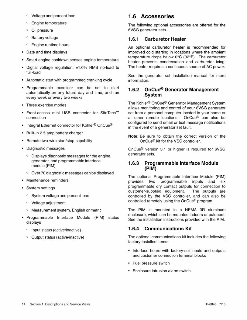
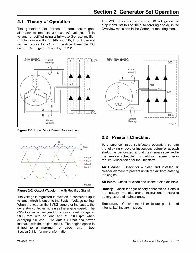
2.1 Theory of Operation
The generator set utilizes a permanent-magnetalternator to produce 3-phase AC voltage. Thisvoltage is rectified using a full-wave 3-phase rectifier(single block rectifier for 36V and 48V, three individualrectifier blocks for 24V) to produce low-ripple DCoutput. See Figure 2-1 and Figure 2-2.
The VSC measures the average DC voltage on theoutput and lists this on the auto-scrolling display, in theOverview menu and in the Generator metering menu.
Figure 2-1
Figure 2-1 Basic VSG Power Connections
Figure 2-2
Figure 2-2 Output Waveform, with Rectified Signal
The voltage is regulated to maintain a constant outputvoltage, which is equal to the System Voltage setting.When the load on the 6VSG generator increases, thegenerator controller increases the engine speed. The6VSG series is designed to produce rated voltage at2300 rpm with no load and at 2900 rpm whensupplying full load. The output current and powerincrease with the engine speed. The engine speed islimited to a maximum of 3300 rpm. SeeSection 3.14.1 for more information.
2.2 Prestart Checklist
To ensure continued satisfactory operation, performthe following checks or inspections before or at eachstartup, as designated, and at the intervals specified inthe service schedule. In addition, some checksrequire verification after the unit starts.
Air Cleaner. Check for a clean and installed aircleaner element to prevent unfiltered air from enteringthe engine.
Air Inlets. Check for clean and unobstructed air inlets.
Battery. Check for tight battery connections. Consultthe battery manufacturer’s instructions regardingbattery care and maintenance.
Enclosure. Check that all enclosure panels andinternal baffling are in place.
KPS_105
KPS_106

18 Section 2 Generator Set Operation TP-6843 7/15
Exhaust System. Check for exhaust leaks andblockages. Check the muffler condition.
• Inspect the exhaust system components for cracks,leaks, and corrosion. Check for tight exhaustsystem connections.
• Check for corroded or broken metal parts andreplace them as needed.
• Check that the exhaust outlet is unobstructed.
Oil Level. Check the oil level before starting thegenerator set and at the intervals given in Section 4,Scheduled Maintenance. Maintain the oil level at ornear, not over, the full mark on the dipstick.
Operating Area. Check for obstructions that couldblock the flow of cooling air. Keep the air intake areaclean. Do not leave rags, tools, or debris on or nearthe generator set.
2.3 Exercising the Generator Set
Operate the generator set without load once eachweek or every 2 weeks for 20 minutes. See Section2.5, Exercise. For instructions to set the exerciser, seeSection 3.6.
2.4 Generator Set Operation
2.4.1 Local Starting and Stopping
Start: Press the RUN button to immediately start thegenerator set.
Stop: Press the OFF button. The engine stops.
Run the generator set with no load for at least 2 minutes to ensure adequate engine cooldown.
2.4.2 Remote Starting and Stopping
The generator set must be in automatic mode forremote operation. Press the AUTO button on the VSCcontroller.
A remote switch connected to terminals 3 and 4 can beused to start and stop the generator set. Close theswitch to start and run the generator set. Open theswitch to stop the generator set.
Run the generator set with no load for at least 2 minutes to ensure adequate engine cooldown.
2.4.3 Engine Start Crank Cycle
The controller attempts to start the generator set threetimes (three crank cycles, 15 seconds crank and 15 seconds off). If the generator set does not start inthree attempts, the system shuts down on anovercrank fault. See Section 2.6.
Cranking 1, 2, and 3 are displayed during the crankcycle. Pressing the OFF button during the crank cyclestops the cranking. No other buttons areacknowledged during the crank cycle.
2.4.4 Engine Cooldown
The engine cooldown time delay allows the engine torun after the loads have been removed.
The engine cooldown time delay is set to 5 minutes.The engine stops before the cooldown time delayexpires if the temperature drops below thecooled-down temperature level, or if the temperaturerises above the high limit during the cooldown cycle.
2.4.5 Automatic Operation
The 6VSG monitors the voltage of a storage batterybank connected to (+) and (–) of the output block todetermine charge condition of the storage battery (seeFigure 2-3).
• If the storage battery voltage falls below theminimum voltage for more than 3 minutes, or if aremote start command is received, the generatorset starts. A remote start command can beactivated by closing the remote start contactsacross 3 and 4 or by a start exercise command.
• When the generator set load falls below theminimum % load for more than 3 minutes, or aremote stop command is received, the generator setstops. A remote stop command can be caused byopening the remote start contacts across 3 and 4 orby the exercise time ending.
The minimum voltage, minimum load, and time delaysare adjustable using a personal computer and Kohler®
SiteTech™ software. Contact your Kohler distributor.

TP-6843 7/15 Section 2 Generator Set Operation 19
Figure 2-3
Figure 2-3 Output Block
2.5 Exercise
The VSC controllers can be set to automatically runthe generator set at the same time and day eachweek. Exercising the generator set weekly or everytwo weeks is required to keep the engine andalternator in good operating condition.
When power is applied to the VSC controller (that is,when the battery is connected), you will be promptedto set the date and time, and then to set the exerciser.
See Section 3.1, VSC Generator Set Controller, formore information
An exercise can be started at any time using Kohler®
OnCue®, or can start automatically according to theexercise schedule programmed on the VSC controller.
Three exercise modes are available. During someexercise modes the engine speed increases anddecreases. This is normal.
1. Unloaded Full Speed Exercise. The generatorregulates the output load below 5% of capacity.The generator will stop after 20 minutes.
2. Unloaded Cycle Exercise. The generator setengine speed varies during the 20-minuteexercise according to the following cycle:
a. The generator set regulates the output loadbelow 5% of capacity for 11 minutes to warmup.
b. The output regulation is moved to the GensetMaximum Percent Capacity for 3 minutes totest ability to output power.
c. The load limit is returned to 5% for 6 minutesto allow the generator to cool down beforestopping.
3. Loaded Full Speed Exercise. The generatoroperates normally. Voltage is regulated to VoltageRegulator Average Voltage Adjustment, and loadis regulated to Genset Maximum PercentCapacity. The generator stops after 20 minutes,regardless of the load on the generator.
2.6 Faults
The VSC controller displays fault messages forgenerator set warnings and shutdowns. Selected faultmessages are shown in Figure 2-5.
2.6.1 Warnings
The controller displays a fault message but thegenerator set does not shut down on a warning. Thecontroller resets automatically after a warningcondition is corrected.
2.6.2 Shutdowns
Under a fault shutdown condition, the generator setshuts down automatically and the controller displays afault message. The OFF LED flashes. In some cases,the engine cooldown cycle runs before the engineshuts down. See Figure 2-5.
Shutdown switches (such as the low oil pressureswitch or high engine temperature switch) on thegenerator set will automatically reset when theproblem is corrected. However, the fault condition atthe controller does not clear until the controller is reset.
The generator set cannot be restarted until the faultcondition is corrected and the controller is reset. SeeSection 2.6.3 for instructions to reset the controllerafter a fault shutdown.
1 2
KPS_043B
1. Positive (+)2. Negative (–)

20 Section 2 Generator Set Operation TP-6843 7/15
2.6.3 Resetting the Controller After a Fault Shutdown
Always identify and correct the cause of a faultshutdown before resetting the controller. Check thefault message displayed on the controller and refer toFigure 2-5 to identify and correct the fault conditionbefore proceeding. Contact an authorizeddistributor/dealer for service, if necessary.
Press the OFF button to reset the controller, or followthe procedure below. See Figure 2-4.
1. While the fault message is displayed, press theSelect button to go to the Overview menu.
2. Press Select again. The active fault message isdisplayed.
3. Press Select. Confirm Clear Fault: NO isdisplayed.
4. Press the UP arrow button. Confirm Clear Fault:YES is displayed.
5. Press the Select button to enter YES and clearthe fault.
6. Press the Select button to return to the overviewmenu. The controller changes to OFF mode.
7. Press AUTO to put the generator set intoautomatic mode.
Figure 2-4
Figure 2-4 Clearing a Fault on the VSC Controller
Figure 2-5
Overview ---->1.2 h
Fault Message
tp6809
Confirm ClearFault: NO
Confirm ClearFault: YES
Fault Message
Press UParrow button.
Fault Message Warning (W) or Shutdown (SD) Condition Check
Accy PwrOver Warning
W Accessory Power Overload. Too many devices on the accessory power port or an over current fault (short circuit) on the accessory controller power output. (Feeds RBUS devices - PIM)
Contact an authorized distributor/dealer for service.
Aux Input SD * Auxiliary input. An optional customer-connected input is closed. (Digital input from optional PIM.)
Check customer-supplied equipment.
Batt Chg Flt W Battery charger fault. Input to PIM from an external battery charger (not the built-in battery charger).
Check external battery charger.
Battery Voltage CrLow
W Engine starting battery voltage is critically low, less than 10.5 VDC.
Check the battery rating and condition.
Check the battery charger operation.Charge or replace the battery.
Battery Voltage High
W Engine starting battery voltage rises above 16 VDC for more than 10 seconds. Inhibited during the engine crank cycle.
Clears when the battery voltage returns to an acceptable level.
Check the battery rating and condition.
Check the battery charger operation.
Battery Voltage Low
W Engine starting battery voltage falls below 12.5 VDC for more than 90 seconds when the engine is not running.
Not operative during the engine crank cycle. Clears when the battery voltage returns to an acceptable level.
Check the battery rating and condition.
Check the battery charger operation.Charge or replace the battery.

TP-6843 7/15 Section 2 Generator Set Operation 21
Figure 2-5 Controller Fault Messages
Enclosure Intrusion Alarm
W The enclosure door is open. (Optional communications kit required.)
Check for evidence of unauthorized access to the generator set. Close and lock the enclosure door.
Engine Oil Pressure Low
SD * The LOP switch indicates low oil pressure for more than 5 seconds. Function becomes active 30 seconds after crank disconnect (30 second inhibit). Note: The low oil pressure shutdown does not protect against low oil level. Check the engine oil level regularly as recommended in Section 4.
Check for leaks in the lubrication system.
Check the oil level and add oil if the level is low.
Fuel Pressure Low
W The fuel pressure switch measures low fuel pressure (below 4.5 inches water column). (Optional communications kit required.)
Check fuel supply and fuel lines.
Engine Speed High
SD * Engine speed exceeds 115% of the normal running speed for more than 0.3 seconds.
Contact an authorized distributor/dealer for service.
Exer Not Sch W Exercise not scheduled. No exercise is scheduled on the controller.
See Section 3.6 for instructions to set the exerciser.
Generator VoltageL1-L2 High
SD * Generator voltage high. Output voltage exceeds 120% of the system nominal voltage for more than 2 seconds.
Contact an authorized distributor/dealer for service.
Lo Crank Vlt W Low cranking voltage. Battery voltage falls below 8 VDC for more than 6 seconds while the starter is engaged.
Charge or replace the battery.
Locked Rotor SD No engine rotation is sensed during cranking. Shuts down 3 seconds after the fault is detected.
Check the battery.
Check for loose connections.
Contact an authorized distributor/dealer for service.
MainPwrOverL Shutdown
SD Main power overload. An over current fault on the controller output (short circuit).
Contact an authorized distributor/dealer for service.
Not in Auto W The generator set is not in Automatic (standby) mode. Remote start and stop commands from a transfer switch or remote switch will be ignored.
Press AUTO to place the generator set in Automatic mode, when appropriate.
Over Crank SD Three unsuccessful starting attempts. Check the fuel supply, spark plug, and battery.
Check for loose connections.
Contact an authorized distributor/dealer for service.
Reserve Oil Empty
W The oil makeup kit reservoir bottle is empty. (Optional communications kit and oil makeup kit required.)
Add oil to the oil makeup kit reservoir.
Speed Sensor Fault
SD Engine speed sensing has failed or engine stalled.
Contact an authorized distributor/dealer for service.
* Engine cooldown runs before shutting down.
Fault Message Warning (W) or Shutdown (SD) Condition Check

22 Section 2 Generator Set Operation TP-6843 7/15
Notes
TP-6843 7/15 Section 3 VSC Controller Operation 23
Section 3 VSC Controller Operation
3.1 VSC Generator Set Controller
All 6VSG generator sets are equipped with the VSCgenerator set controller.
The VSC controls generator set and the optionalProgrammable Interface Module (PIM) orCommunications Kit.
The VSC controller features include:
• Two-line x 16 character backlit digital display withadjustable contrast
• OFF, AUTO, and RUN generator set master controlbuttons
• Generator set status indicating LEDs (OFF, AUTO,RUN)
• Up, Down, and Select buttons for navigationthrough menus and adjustments
• Power system indicator LEDs to show power outputof the generator
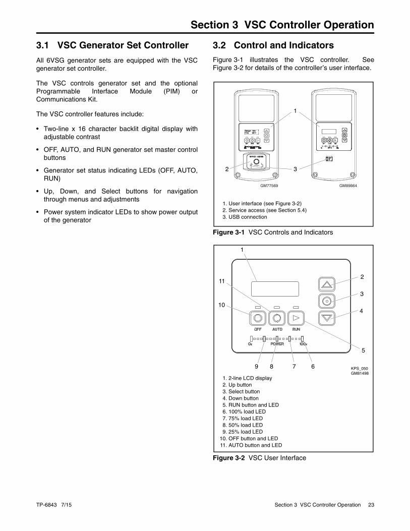
3.2 Control and IndicatorsFigure 3-1 illustrates the VSC controller. SeeFigure 3-2 for details of the controller’s user interface.
Figure 3-1
Figure 3-1 VSC Controls and Indicators
Figure 3-2
Figure 3-2 VSC User Interface
GM89864GM77569
1
2 3
1. User interface (see Figure 3-2)2. Service access (see Section 5.4)3. USB connection
1
10
3
2
5
11
4
6789 KPS_050GM81498
1. 2-line LCD display2. Up button3. Select button4. Down button5. RUN button and LED6. 100% load LED7. 75% load LED8. 50% load LED9. 25% load LED
10. OFF button and LED11. AUTO button and LED
24 Section 3 VSC Controller Operation TP-6843 7/15
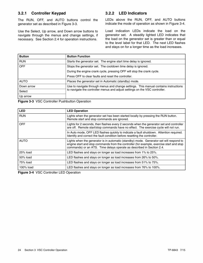
3.2.1 Controller Keypad
The RUN, OFF, and AUTO buttons control thegenerator set as described in Figure 3-3.
Use the Select, Up arrow, and Down arrow buttons tonavigate through the menus and change settings, ifnecessary. See Section 2.4 for operation instructions.
3.2.2 LED Indicators
LEDs above the RUN, OFF, and AUTO buttonsindicate the mode of operation as shown in Figure 3-4.
Load indication LEDs indicate the load on thegenerator set. A steadily lighted LED indicates thatthe load on the generator set is greater than or equalto the level label for that LED. The next LED flashesand stays on for a longer time as the load increases.
Figure 3-3
Figure 3-3 VSC Controller Pushbutton Operation
Figure 3-4
Figure 3-4 VSC Controller LED Operation
Button Button Function
RUN Starts the generator set. The engine start time delay is ignored.
OFF Stops the generator set. The cooldown time delay is ignored.
During the engine crank cycle, pressing OFF will stop the crank cycle.
Press OFF to clear faults and reset the controller.
AUTO Places the generator set in Automatic (standby) mode.
Down arrow Use to navigate through menus and change settings. This manual contains instructions to navigate the controller menus and adjust settings on the VSC controller. Select
Up arrow
LED LED Operation
RUN Lights when the generator set has been started locally by pressing the RUN button. Remote start and stop commands are ignored.
OFF Lights for 2 seconds, then flashes every 2 seconds when the generator set and controller are off. Remote start/stop commands have no effect. The exercise cycle will not run.
In Auto mode, OFF LED flashes quickly to indicate a fault shutdown. Attention required. Identify and correct the fault condition before resetting the controller.
AUTO Lights when the generator is in automatic (standby) mode. Generator set will respond to engine start and stop commands from the controller (for example, exercise start and stop commands) or an ATS. Time delays operate as described in Section 2.4.
25% load LED flashes and stays on longer as load increases from 1% to 25%.
50% load LED flashes and stays on longer as load increases from 26% to 50%.
75% load LED flashes and stays on longer as load increases from 51% to 75%.
100% load LED flashes and stays on longer as load increases from 76% to 100%.

TP-6843 7/15 Section 3 VSC Controller Operation 25
3.2.3 LCD Display
The controller is equipped with a two-line x16-character backlit digital display with adjustablecontrast. When the generator is running, the controllerautomatically scrolls through the displays shown inFigure 3-5. The VSC controller measures anddisplays the average DC output voltage on theauto-scrolling display. When the system is in standbymode and the controller is in AUTO, the screensshown in Figure 3-6 are displayed.
When a fault or warning condition exists, the controllerwill show the corresponding message. SeeSection 2.6 for more information about faults.
Controller menus display power system information,including status information for the engine, generator,and optional RBUS accessories, exercise settings,and event history. Some menus allow changes to thecontroller settings. See Sections 3.7 through 3.18 formenu diagrams.
Figure 3-5
Figure 3-5 Autopaging Displays, Generator Running
The display contrast is adjustable. Navigate to theGenset System menu and step down to the Contrastscreen. Press the Select button, and then use the upand down arrow buttons to adjust the contrast. SeeSection 3.5, Changing Settings, and Section 3.14,Genset System Menu.
The display backlight turns off after about a minute ofno activity. The backlight turns on when a button ispressed or when the generator set starts.
Figure 3-6
Figure 3-6 Autopaging Displays, Automatic Mode
Genset StatusRunning
Voltage: 54VLoad: 73%
Engine: 125FOil Pressure: Okay
Battery13.3V
Engine Runtime:100.6 h
Date: 02DEC2011Time: HR:MNpm
Active Alert
Sample data shown.
tp6804
Battery13.3V
Engine Runtime:100.6 h
Date: 02DEC2011Time: HR:MNpm
Next Maintenance:150 h or Mar2012
Sample data shown.
Genset StatusStandby
Active Alert
Next Exercise:09:00p 09Dec2011

26 Section 3 VSC Controller Operation TP-6843 7/15
3.3 Controller PowerThe VSC controller is powered by the generator setengine starting battery and the built-in battery charger.
Note: To disconnect controller power, disconnect theAC power to the generator set starting battery.
If controller power is disconnected and reconnected,you will be prompted to set the time, date, andexerciser. The first setting will flash. Press the Up andDown arrow buttons to change the setting. PressSelect to save the setting and move on to the next.Repeat until all settings are saved and the controllerreturns to the main menu. See Section 3.5 for moredetailed instructions to change settings on the VSC.See Section 3.6 for more detailed instructions to setthe exerciser or change the exercise settings.
3.4 Battery Charging
The controller includes a built-in battery charger tomaintain the engine starting battery. The VSCcontroller monitors the battery voltage and provides aconstant 13.8 ±2% VDC voltage and maximum2.5 amps to charge the battery.
The installer must connect 120 VAC/60Hz power on abreaker-protected circuit for the built-in batterycharger.
3.5 Changing Settings
Some settings can be changed from the controllerkeypad. The controller settings and generator setoutput are factory-set and should not require fieldadjustment under normal circumstances. Check andadjust the settings and/or output when:
• The controller has been replaced.
• The voltage requires adjustment for a particularapplication.
• Troubleshooting generator set problems.
Have controller setup and adjustment performed onlyby an authorized Kohler distributor/dealer orauthorized representative.
The following procedure explains how to changesettings. See Figure 3-7 for an example using theDate and Time settings.
Note: Use caution when navigating the controllermenus. In some menus, pressing the Selectbutton can enable editing of the controllersettings. Changing the settings to incorrectvalues can adversely affect generator setoperation or render the unit inoperable.
3.5.1 Procedure to Change Settings
1. Press the Select button to enter the main menu.
2. Press the down arrow button until the desiredmenu is displayed.
3. Press the Select button to enter the gensetsystem displays. See Figure 3-10.
4. Press the down arrow button to step through thegenerator set system settings.
5. To change any of the genset system settings,press the Select button. The selected settingflashes.
6. Press the up or down arrow buttons to increaseor decrease the setting.
7. When the desired setting is shown, press Select.The value stops flashing. If there are additionaladjustable settings on the screen, the next settingflashes. For example, in the date menu, the day,month, and year can be adjusted. The settingsare saved on completion of step 7.
8. Repeat steps 6 and 7 for each setting on thescreen.
9. Press the down arrow to step to the next screen.
10. To exit, press the down arrow button until Returnis displayed. Press the Select button to exit themenu.
11. Press the AUTO or OFF button to exit the mainmenu.
Note: If no buttons are pushed, the controllerexits the menus and returns to thegenerator set status display after 5 minutes.

TP-6843 7/15 Section 3 VSC Controller Operation 27
Figure 3-7
Figure 3-7 Changing Settings
1. Press the Select button to enter the main menu.
2. Press the down arrow button until the desiredmenu is displayed. See Figure 3-9. Date and Timeare used for this example.
3. Press the Select button to enter the Date and Timemenu.
4. To change the date and time settings, press theSelect button again. The year will flash.
5. Press the up or down arrow buttons to change theyear.
6. When the correct year is shown, press the Selectbutton. The year is saved and the next setting(month) flashes.
7. Repeat steps 5 and 6, using the arrow and selectbuttons to set the month and the date.
Press:
Changing Date/Time
Press: Display:Overview ---->
1.2 h
Display:
Press: Display:
Press: Display:
Date ---->
and Time
Date:
05Dec2011
8. When the correct date is shown, press the Selectbutton. The saved date is shown.
9. Press the down arrow button to step to the nextmenu.
10. Repeat steps 5 and 6, using the arrow and selectbuttons to set and save the time.
Note: To change from am to pm, press the up arrowkey to increase the hour until the correct hourand pm is displayed.
11. In the time format menu, press Select and thenpress the up or down arrow button to change theformat, 12 hr. or 24 hr. Press Select to save thedisplayed format.
12. Press the down arrow button. Return isdisplayed.
13. Press Select to return to the Date and Timemenu.
14. Press the Up or Down arrow buttons to step to adifferent menu.
15. Press Auto to signal the controller to exit themenus and return to the generator set statusdisplay.
Note: If no buttons are pressed, the controller returnsto the status display after 5 minutes.
Press: Display:OR
Press: Display:
Press: Display:<---- Return
Press: Display:
Time:
01:49pm
Date ---->
and Time
AUTO
Press: Display:Genset State
Standby
Date:
05Dec2011
Date:
05Dec2012
Press: Display:Date:
05Dec2012
Press: Display:Date:
03Jan2012

28 Section 3 VSC Controller Operation TP-6843 7/15
3.6 Setting the Exerciser
Set the exerciser to automatically run the generator setfor 20 minutes every week or every two weeks.
3.6.1 Setting the Exerciser at Controller Power-up
When battery power is connected to the controller, youwill be prompted to set the date and time, and then toset the exerciser.
The first setting will flash. Press the Up and Downarrow buttons to change the setting. Press Select tosave the setting and move on to the next. SeeSection 3.5 for more detailed instructions to changesettings on the VSC.
If the battery is disconnected and reconnected duringgenerator set maintenance or service, the time, date,and exercise settings will need to be re-entered.
3.6.2 Changing the Exercise Settings
This section explains how to change the exercisesettings after the initial setup.
Follow the procedure below and see the flowchart inFigure 3-8 to set the exercise time and date, mode,and frequency.
Procedure to Set the Exerciser1. Press the AUTO button on the controller.
2. Press the Select button to go to the main menu.See Figure 3-9.
3. Press the down arrow button to step to theGenset System menu.
4. Press the Select button to enter the Gensetsystem menu. See Figure 3-11.
5. Use the down arrow button to step to the NextExercise menu. If the exerciser is not set, NoExercise Scheduled will be displayed.
6. Press and HOLD the Select button to enableediting.
7. Press the Select button. The setting flashes toshow that it can be changed. For example, HRflashes to show that the hour can be changed.
8. Press the Up or Down arrow buttons to changethe setting.
9. Press the Select button to save the setting andmove to the next. For example, save HR settingand move to MN.
10. Repeat steps 5 through 9 to change the next itemon the line until the desired settings aredisplayed.
11. Press Select to save after all settings have beenselected. Settings will stop flashing.
12. Set the exercise frequency (weekly or every twoweeks). Weekly exercises are recommended.
13. Press the down arrow button to step to the Returnmenu. Press the Select button to return to themain menu.
After a scheduled exercise run, the next exercise timeand date will be updated automatically based on theExercise Frequency setting.
Exerciser Reset
To reset the exerciser to run at a different day and/ortime or to change the exercise mode, follow theprocedure in Section 3.6.2 to change the exercisersettings.

TP-6843 7/15 Section 3 VSC Controller Operation 29
Figure 3-8
Figure 3-8 Procedure to Set the Exerciser on the VSC Controller
tp6804
System Voltage:
54.0V
Genset ---->
System
Auto Stop Load: (%)
Fuel Type:Natual Gas
Load Limit: (%)
HOLD:
Next Exercise
HR:MN PM MM/DD/YY
HOLD:
Exercise Freq:
Weekly/Bi-Weekly
Auto Start Volt: (V)
Language:English
<---- Return
Next Exercise *
HR:MN PM MM/DD/YY
Exercise Freq:
Weekly
Exercise Mode:
Loaded
HOLD:
Exercise Mode:Loaded Full SpUnloaded CycleLoaded Full Sp
Contrast:
50
* If the exerciser has not been set, No Exercise Sch will be displayed.
30 Section 3 VSC Controller Operation TP-6843 7/15
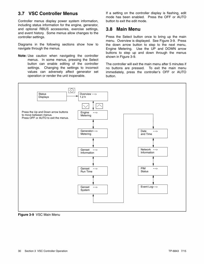
3.7 VSC Controller Menus
Controller menus display power system information,including status information for the engine, generator,and optional RBUS accessories, exercise settings,and event history. Some menus allow changes to thecontroller settings.
Diagrams in the following sections show how tonavigate through the menus.
Note: Use caution when navigating the controllermenus. In some menus, pressing the Selectbutton can enable editing of the controllersettings. Changing the settings to incorrectvalues can adversely affect generator setoperation or render the unit inoperable.
If a setting on the controller display is flashing, editmode has been enabled. Press the OFF or AUTObutton to exit the edit mode.
3.8 Main Menu
Press the Select button once to bring up the mainmenu. Overview is displayed. See Figure 3-9. Pressthe down arrow button to step to the next menu,Engine Metering. Use the UP and DOWN arrowbuttons to step up and down through the menusshown in Figure 3-9.
The controller will exit the main menu after 5 minutes ifno buttons are pressed. To exit the main menuimmediately, press the controller’s OFF or AUTObutton.
Figure 3-9
Figure 3-9 VSC Main Menu
Overview ---->1.2 h
Engine ---->Metering
Generator---->Metering
Genset ---->Information
Genset ---->Run Time
Date ---->and Time
Genset ---->System
Event Log---->
PIM ---->Status
Network ---->Information
StatusDisplays
Press the Up and Down arrow buttonsto move between menus.Press OFF or AUTO to exit the menus.

TP-6843 7/15 Section 3 VSC Controller Operation 31
3.9 Overview Menu Figure 3-10
Figure 3-10 Overview Menu
3.10 Engine Metering Menu
The engine metering menu displays engine statusinformation as shown in Figure 3-11. This menudisplays status information only. No settings can bechanged from this menu.
Figure 3-11
Figure 3-11 Engine Metering Menu
Overview ---->1.2 h
Active Alert(if any)
Genset StatusStandby
Generator: 54V% Load 73%
Engine: 125FOil Pressure: OK
Battery:13.3V
Engine Runtime:100.6 h
Date: 02DEC2011Time: HR:MNpm
Next Exercise:09:00p 09Dec2011
Next Maintenance:150 h or Mar2012
SW Version:4.06
<---- Return
tp6810
Eng Speed:2300 R/min
Battery:13.3 V
<---- Return
Engine ---->Metering
Oil Pressure:Switch: OK
Oil Temperature:125 F

32 Section 3 VSC Controller Operation TP-6843 7/15
3.11 Generator Metering MenuThe generator metering menu displays the generatorvoltage and % load. See Figure 3-12.
3.11.1 Calibration
The calibration mode can be entered from theGenerator Metering menu. Contact aKohler-authorized distributor/dealer for service.
The Reset Calibration menu allows you to set thereadings back to the default settings after calibration, ifnecessary. See Figure 3-12.
Figure 3-12
Figure 3-12 Generator Metering Menu
DANGER!
Hazardous voltage.Will cause severe injury or death.
This equipment must be installedand serviced by qualified electricalpersonnel.
Generator ---->Metering
ResetCalibration
<---- Return
ResetCalib? No
Volts:54.0V
ResetCalib? Yes
Load:73%
ResetCalibration

TP-6843 7/15 Section 3 VSC Controller Operation 33
3.12 Generator Set Information Menu
The generator set model number and serial numbersare displayed (see Figure 3-13). No changes areallowed from this menu.
Model and serial numbers are factory-set and shouldnot require changes in the field, except in the eventthat the controller is being replaced. A personalcomputer running Kohler® SiteTech™ software isrequired to enter the generator set model number andserial numbers on a replacement controller. Contactan authorized Kohler distributor/dealer for service.
Figure 3-13
Figure 3-13 Generator Set Information Menu
3.13 Genset Run Time MenuThe data shown in Figure 3-14 are displayed. Nochanges are allowed from this menu.
The Next Maintenance menu shows the number ofhours of generator set operation until maintenance isrequired. The estimated date for the next scheduledmaintenance is also displayed. The maintenancereminder intervals are based on the enginemanufacturer’s recommendation for changing the oil.See Section 4, Scheduled Maintenance, formaintenance instructions.
After changing the oil and performing otherrecommended maintenance, go to the Overview menuto reset the maintenance timer. See Section 4.2.5 forinstructions to reset the maintenance timer.
Figure 3-14
Figure 3-14 Generator Set Run Time Menu
tp6804
Genset M/N:6VSG-48V
Genset S/N:
Controller S/N:
<---- Return
Genset ---->Information
########
########
tp68
Eng Runtime:
100.6 h
Eng Starts:
127
<---- Return
Genset ---->Run Time
Next Maintenance:
150 h or Mar2012

34 Section 3 VSC Controller Operation TP-6843 7/15
3.14 Genset System MenuThe genset system menu displays the systeminformation shown in Figure 3-19. Generator sets arefactory-set and should not require changes to thesystem settings in the field.
A Kohler-authorized distributor or dealer can adjustthese settings, if necessary. If the generator set isreconnected to a different voltage or the systemsettings require adjustment for some other reason, seeSection 3.5 for instructions to enable editing andchange the system settings.
Note: Use caution when navigating the controllermenus. In some menus, pressing the Selectbutton can enable editing of the controllersettings. Changing the settings to incorrectvalues can adversely affect generator setoperation or render the unit inoperable.
3.14.1 System Parameters for Battery Bank Charging
The following system parameters can be viewed in theGenset System menu on the user interface on thegenerator set’s VSC controller.
• System Voltage
• Auto Start Voltage
• Auto Stop Load (%)
• Load Limit
Note: Changing these settings can damage yourgenerator set and batteries. Always refer to theinformation provided by the battery bankmanufacturer for the correct voltage and chargecurrent limits for your batteries. Contact anauthorized Kohler distributor or dealer forassistance if the default settings are notappropriate for the battery bank.
System Voltage: The system voltage is the outputvoltage of the generator set. Default values are shownin Figure 3-15. The system voltage is set to therequired output voltage to properly support the loadand charge the battery. Do not confuse this value withthe voltage designation of the battery stack. Forexample, four 12V batteries in series results in a 48Vbattery stack, but the output voltage needed to chargethe battery stack is 54V.
Figure 3-15
Figure 3-15 System Voltage Default Settings
Refer to the battery manufacturer’s documentation forthe recommended charging voltage. If the systemvoltage needs to be changed, contact an authorizedKohler distributor or dealer.
Note: Setting the system voltage to a higher valuethan the factory default setting will decrease thepower output of the generator set.
A 6VSG set at the system voltage shown inFigure 3-15 will have an output of 6 kW. If the systemvoltage is set to a higher value, the output currentdecreases. The available power output alsodecreases below 6 kW due to the limits on the enginespeed. The graphs in Figure 3-17 illustrate the effectof changing the system voltage.
Auto Start Volt: The 6VSG will automatically startwhen the battery bank voltage has reached or fallenbelow this value for 180 seconds (3 minutes). Defaultsettings are shown in Figure 3-16.
Figure 3-16
Figure 3-16 Auto Start Voltage
Note: The 3-minute (180-second) time delay can bechanged using a personal computer (laptop)and Kohler® SiteTech™ software. Contact aKohler authorized distributor or dealer to adjustthe delay setting, if necessary.
Nominal Voltage 24V 36V 48V
Default System Voltage, VDC 27 40.5 54
Nominal Voltage 24V 36V 48V
Default Auto Start Voltage, VDC 25 37.5 50

TP-6843 7/15 Section 3 VSC Controller Operation 35
Figure 3-17
Figure 3-17 Effect of Changing the System Voltage Setting
Auto Stop Load: The auto stop load is set as apercentage of full load. As the battery bankapproaches the fully charged state, the charge rateslows, and the load on the generator set decreases.The 6VSG will automatically stop when the load hasreached or fallen below the Auto Stop Load setting for180 seconds (3 minutes). The default setting is 40%load.
Load Limit (%): This setting limits the current outputto the maximum charge rate specified by the batterymanufacturer or load in the application. The defaultsetting is 100%, which gives the maximum currentvalues shown in Figure 3-18. Refer to the batterymanufacturer's recommended maximum charge rateand contact an authorized Kohler distributor or dealerif the setting needs to be changed.
Figure 3-18
Figure 3-18 Maximum Charge Current at Default Load Limit Setting of 100%
KPS_104
Load Limit = (Recommended charging voltage (VDC) x Maximum charging current (amps)) x 100
6000 watts
Nominal Voltage 24V 36V 48V
System Voltage, VDC 27 40.5 54
Maximum Current at 100% Load Limit, Amps 222 148 111
36 Section 3 VSC Controller Operation TP-6843 7/15
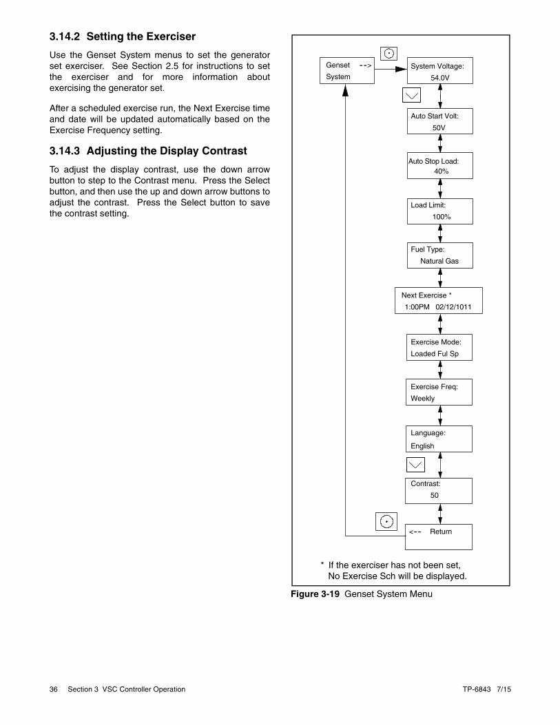
3.14.2 Setting the Exerciser
Use the Genset System menus to set the generatorset exerciser. See Section 2.5 for instructions to setthe exerciser and for more information aboutexercising the generator set.
After a scheduled exercise run, the Next Exercise timeand date will be updated automatically based on theExercise Frequency setting.
3.14.3 Adjusting the Display Contrast
To adjust the display contrast, use the down arrowbutton to step to the Contrast menu. Press the Selectbutton, and then use the up and down arrow buttons toadjust the contrast. Press the Select button to savethe contrast setting.
Figure 3-19
Figure 3-19 Genset System Menutp6804
System Voltage:
54.0V
50V
40%
100%
Genset ---->
System
Auto Stop Load:
Load Limit:
Natural Gas
Fuel Type:
Auto Start Volt:
Language:
<---- Return
Next Exercise *
1:00PM 02/12/1011
Exercise Freq:
Weekly
English
Exercise Mode:
Loaded Ful Sp
Contrast:
50
* If the exerciser has not been set, No Exercise Sch will be displayed.

TP-6843 7/15 Section 3 VSC Controller Operation 37
3.15 Date and Time MenuThe date and time will typically be set at controllerpowerup. To change the date, time, or time format(12 hour or 24 hour), use the Date and Time menu.See Figure 3-20.
3.16 Networking Information Menus
Use the networking menus to view and adjustcommunication settings for systems with remoteRBUS devices such as a PIM, and for systems thatuse the Kohler® OnCue® Generator ManagementSystem.
RBUS is a proprietary RS-485 communicationsprotocol.
The Networking Information menu leads to submenusfor network and RBUS communication settings. SeeFigure 3-21.
Figure 3-20
Figure 3-20 Date and Time Menu
Figure 3-21
Figure 3-21 Networking Information Menu
tp6804
Date:
02Dec2011
Time:
12:34pm
Time Format:
12hr
Date andTime
To change the date and time, press the Select buttonSee Figure 3-7 for instructions.
<---- Return
tp6810
Networking---->Information
Networking---->Status
NS
RBUS ---->Information
RB
<---- Return
Networking---->Configuration
NC
See Figure 3-22.
See Figure 3-23.
See Figure 3-24.
38 Section 3 VSC Controller Operation TP-6843 7/15
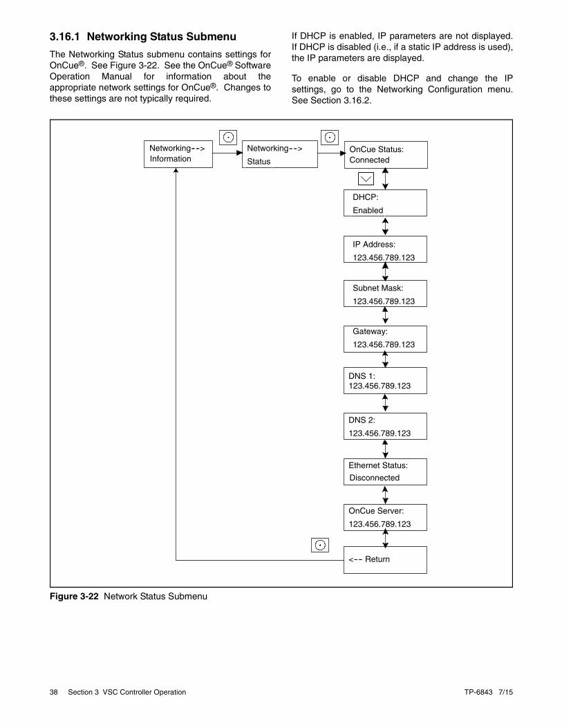
3.16.1 Networking Status Submenu
The Networking Status submenu contains settings forOnCue®. See Figure 3-22. See the OnCue® SoftwareOperation Manual for information about theappropriate network settings for OnCue®. Changes tothese settings are not typically required.
If DHCP is enabled, IP parameters are not displayed.If DHCP is disabled (i.e., if a static IP address is used),the IP parameters are displayed.
To enable or disable DHCP and change the IPsettings, go to the Networking Configuration menu.See Section 3.16.2.
Figure 3-22
Figure 3-22 Network Status Submenu
tp68
IP Address:
123.456.789.123
Gateway:
123.456.789.123
<---- Return
Subnet Mask:
123.456.789.123
DHCP:
Enabled
Ethernet Status:
Disconnected
DNS 1:123.456.789.123
DNS 2:
123.456.789.123
OnCue Server:
123.456.789.123
OnCue Status:Connected
Networking---->
Status
Networking---->Information

TP-6843 7/15 Section 3 VSC Controller Operation 39
3.16.2 Networking Configuration Submenu (OnCue® Password)
The networking Configuration menu includes settingsused for communication with the Kohler® OnCue®
Generator Management System. See Figure 3-24.
For most applications, DHCP is enabled and the IPsettings cannot be changed from the controllerkeypad. If DHCP is enabled, IP parameters are notdisplayed.
If DHCP is disabled (i.e., if a static IP address isrequired), then the IP parameters can be modified.For applications that require static IP addresses, pressand hold the select button to enable editing, disableDHCP, and then step to the next parameters and enterthe information.
If an error occurs while setting a parameter, an errormessage is displayed and then the controller exits theedit mode. Previous settings are preserved.
Password
For the initial OnCue® setup, you will be required toreset the OnCue® password on the VSC controller,and then enter it into the OnCue® software. To resetthe password, follow the instructions in Figure 3-22.
Note: The password is displayed for only 10 seconds.Be sure to write down the password and serialnumber.
A new password is generated each time the resetpassword procedure is performed. If the password isreset after the OnCue® system has been set up, theconnection will be lost. Enter the new password inOnCue® to reconnect.
Figure 3-23
Figure 3-23 Network Configuration Submenu
tp6804
<---- Return
DHCP:Enabled
Reset OnCuePassword
Reset OnCuePassword? No
S/N: 1234567New PW: 12345
Press Select to enter YESor NO as displayed. Newpassword is displayed forapproximately 10 seconds.
NetworkingConfiguration
HOLD
Reset OnCuePassword? Yes
UP arrow for YES,Down arrow for NO.
Networking---->Information
Networking---->Status
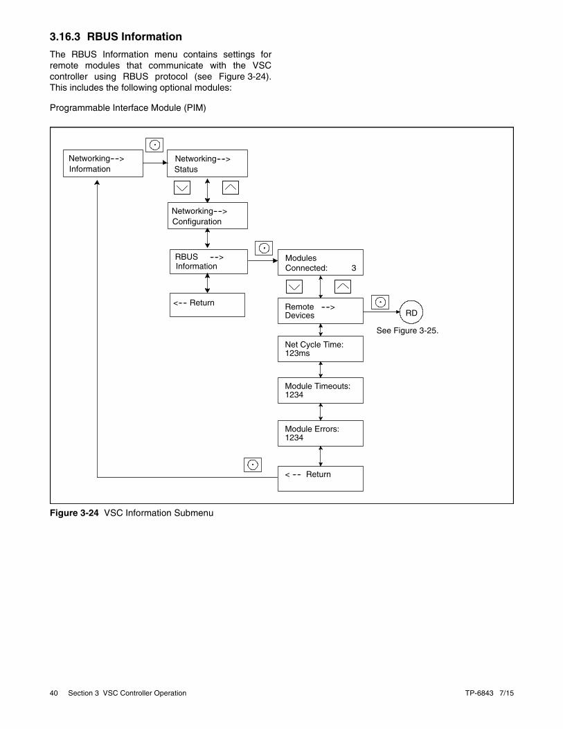
40 Section 3 VSC Controller Operation TP-6843 7/15
3.16.3 RBUS Information
The RBUS Information menu contains settings forremote modules that communicate with the VSCcontroller using RBUS protocol (see Figure 3-24).This includes the following optional modules:
Programmable Interface Module (PIM)
Figure 3-24
Figure 3-24 VSC Information Submenu
tp6804
ModulesConnected: 3
Module Timeouts:1234
Net Cycle Time:123ms
Module Errors:1234
< ---- Return
RDRemote ---->Devices
See Figure 3-25.
Networking---->Information
Networking---->Status
RBUS ---->Information
<---- Return
Networking---->Configuration

TP-6843 7/15 Section 3 VSC Controller Operation 41
3.16.4 Remote Devices Submenu
Check the status of remote devices communicatingthrough RBUS (see Figure 3-25). Device types caninclude:
Programmable Interface Module (PIM)
The serial numbers for the PIM are printed on thecircuit boards inside the enclosures.
Figure 3-25
Figure 3-25 Remote Devices Submenu
tp6804
Module Status:Connected
Firmware Ver.:122
Module ID:12
S/N: XXXXXXXXX<<*DeviceType*>>
Return ---->
S/N: XXXXXXXXX<<*DeviceType*>>
Comm. Errors:12345
Comm. Timeouts:12345
(Dis)Connected:MM/DD/YY 12:12 PM
<---- Return
Connected: Displays the date and time that thedevice was connected.Disconnected: Displays the last date and time ofsuccessful communication.
Remote ---->Devices
From Figure 3-24:

42 Section 3 VSC Controller Operation TP-6843 7/15
3.17 Programmable Interface Module (PIM) Status Menu
Note: The PIM status menu appears if aprogrammable interface module (PIM) or acommunications kit interface board (IB) isconnected.
The PIM status menu displays the status of inputs andoutputs connected to the programmable interfacemodule (PIM) or communications kit interface board(IB). See Figure 3-26. This is a status display menuonly. Input and output settings cannot be changedfrom the VSC controller’s user interface.
A personal computer running Kohler® SiteTech™
software is required to change the input and outputsettings for the PIM. Contact an authorized distributoror dealer for service.
The Kohler® OnCue® Management System can beused to turn the PIM outputs on and off. See theOnCue® Software Operation Manual for instructions.
The input and output settings for the communicationskit interface board are factory set and locked.
Figure 3-26
Figure 3-26 Programmable Interface Module (PIM) Status Menu
*
* PIM Status displays the interface board status if the optional communications kit with factory-installed interface board is installed.
PIMStatus:
PIM 1 ---->
<---- Return
Input 1In/Active
Output 1:In/Active
Input 2In/Active
Output 2:In/Active
Output 3:In/Active
Output 4:In/Active
Output 5:In/Active
Output 6:In/Active
<---- Return

TP-6843 7/15 Section 3 VSC Controller Operation 43
3.18 Event LogThe event log displays up to 1000 controller faults andnotices, starting with the most recent event. Eventsare numbered 1-1000, with 1 being the most recent.Each event is displayed with the date and time of theevent, the number of the event, a code to indicatewhether the event was a warning (W), shutdown (S),or informational notice (I), the engine hours at the timeof the event, and the event description. SeeFigure 3-27.
3.18.1 Procedure to View Event History
1. Press Select to enter the main menu.
2. Press the down arrow to step down to the eventlog.
3. Press Select to display the most recent event.
4. Press the down arrow to step to the next event.
5. Use the up and down arrow buttons to viewevents.
6. Press the Select button to exit the event log.
To stop viewing the event history before the last event,press the select button to return to the main menu.
Figure 3-27
Figure 3-27 Event Log
tp6810
Event Log ---->Date MO/DA/YEAR
time HR:MN
event number, W/S/I, engine hours
event name
Press UP and Down arrowbuttons to scroll through events
Date MO/DA/YEAR
time HR:MN
event number, W/S/I, engine hours
event name
Press Select button at any time toreturn to the main menu.

44 Section 3 VSC Controller Operation TP-6843 7/15
Notes

TP-6843 7/15 Section 4 Scheduled Maintenance 45
Section 4 Scheduled Maintenance
Disabling the generator set. Accidental starting cancause severe injury or death. Before working on thegenerator set or equipment connected to the set, disable thegenerator set as follows: (1) Press the generator setOFF/RESET button to shut down the generator set. (2)Disconnect the power to the battery charger, if equipped. (3)Remove the battery cables, negative (–) lead first.Reconnect the negative (–) lead last when reconnecting thebattery. Follow these precautions to prevent the starting ofthe generator set by the remote start/stop switch.
Servicing the exhaust system. Hot parts can causesevere injury or death. Do not touch hot engine parts. Theengine and exhaust system components become extremelyhot during operation.
4.1 Scheduled Maintenance
Refer to the following service schedules and theruntime hours displayed on the controller display toschedule routine maintenance. Intervals are shown inhours of operation and/or time intervals (i.e. weekly,monthly, quarterly, etc.) Have an authorizeddistributor/dealer service the generator set at thedesignated intervals in the service schedule for the lifeof the generator set. Service units subject to extremeweather, long operating hours, or dusty or dirtyconditions more frequently.
Contact an authorized distributor/dealer for parts.
WARNING!
Accidental starting.Can cause severe injury or death.
Disconnect the battery cables beforeworking on the generator set.Remove the negative (–) lead firstwhen disconnecting the battery.Reconnect the negative (–) lead lastwhen reconnecting the battery.
WARNING!
Hazardous voltage. Moving parts.Can cause severe injury or death.
Operate the generator set only whenall guards and electrical enclosuresare in place.
WARNING!
Hot engine and exhaust system.Can cause severe injury or death.
Do not work on the generator setuntil it cools.

46 Section 4 Scheduled Maintenance TP-6843 7/15
4.1.1 Service Schedule, 6VSG Models
System Component or Procedure See
Section
Procedure
FrequencyVisually Inspect Check Change Clean Test
Fuel
Flexible lines and connections X R Quarterly
Main tank supply level (if LPG fueled) X Weekly
Fuel piping X Yearly
Lubrication 4.2
Oil level X X 8 hours or before use
Crankcase breather hose X Yearly or 500 hours
Change oil X Yearly or 100 hours ‡
Replace filter X Yearly or 200 hours
Cooling 4.5
Air ducts, louvers X X Yearly
Exhaust Line 4.6
Leakage X X Weekly
Insulation, fire hazards X Yearly
Obstructions or combustible materials near exhaust outlet X Weekly
DC Electrical System 4.7
Battery charger operation, charge rate (if equipped) X Monthly
Remove corrosion, clean and dry battery and rack X X Yearly
Clean and tighten battery terminals and inspect boots X X Yearly
Battery electrolyte level and specific gravity * X Yearly
AC Electrical System
Tighten control and power wiring connections X Yearly
Remote control system (if equipped) X Monthly
Visible wear or damage X Quarterly
Wire abrasions where subject to motion X X 6 months
Wire-cable insulation condition X 3 years or 500 hours
Engine and Mounting
Visible wear or damage X Weekly
Air cleaner and precleaner service † 4.4 R Yearly or 100 hours
Spark plugs 4.3 X Yearly or 300 hours
Replace stepper motor coupling and bushing D 500 hours
Generator
Visible wear or damage X Quarterly
Exercise generator set X Weekly
Brushes and collector ring D D Yearly
Measure and record resistance readings of windings with insulation tester (Megger®, with SCR assembly or rectifier and load leads disconnected) *
D 3 years
General Condition of Equipment
Evidence of vibration, leakage, excessive noise, temperature, or deterioration X X X Weekly
Interior of sound enclosure X X Quarterly
* Not necessary for maintenance-free batteries. X Action
† Service more frequently under extremely dusty/dirty conditions. D Authorized distributor/dealer only
‡ Yearly or 250 hours if equipped with optional Oil Makeup Kit. R Replace as necessary
Megger® is a registered trademark of Biddle Instruments.
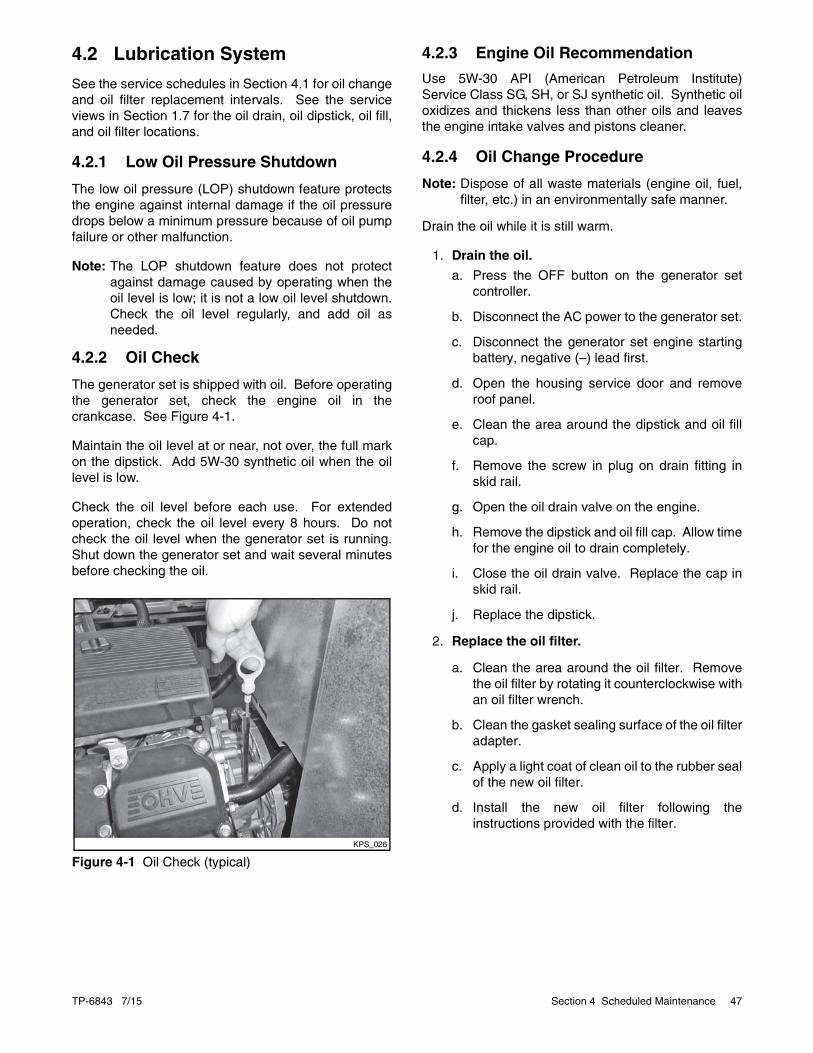
TP-6843 7/15 Section 4 Scheduled Maintenance 47
4.2 Lubrication System
See the service schedules in Section 4.1 for oil changeand oil filter replacement intervals. See the serviceviews in Section 1.7 for the oil drain, oil dipstick, oil fill,and oil filter locations.
4.2.1 Low Oil Pressure Shutdown
The low oil pressure (LOP) shutdown feature protectsthe engine against internal damage if the oil pressuredrops below a minimum pressure because of oil pumpfailure or other malfunction.
Note: The LOP shutdown feature does not protectagainst damage caused by operating when theoil level is low; it is not a low oil level shutdown.Check the oil level regularly, and add oil asneeded.
4.2.2 Oil Check
The generator set is shipped with oil. Before operatingthe generator set, check the engine oil in thecrankcase. See Figure 4-1.
Maintain the oil level at or near, not over, the full markon the dipstick. Add 5W-30 synthetic oil when the oillevel is low.
Check the oil level before each use. For extendedoperation, check the oil level every 8 hours. Do notcheck the oil level when the generator set is running.Shut down the generator set and wait several minutesbefore checking the oil.
Figure 4-1
Figure 4-1 Oil Check (typical)
4.2.3 Engine Oil Recommendation
Use 5W-30 API (American Petroleum Institute)Service Class SG, SH, or SJ synthetic oil. Synthetic oiloxidizes and thickens less than other oils and leavesthe engine intake valves and pistons cleaner.
4.2.4 Oil Change Procedure
Note: Dispose of all waste materials (engine oil, fuel,filter, etc.) in an environmentally safe manner.
Drain the oil while it is still warm.
1. Drain the oil.
a. Press the OFF button on the generator setcontroller.
b. Disconnect the AC power to the generator set.
c. Disconnect the generator set engine startingbattery, negative (–) lead first.
d. Open the housing service door and removeroof panel.
e. Clean the area around the dipstick and oil fillcap.
f. Remove the screw in plug on drain fitting inskid rail.
g. Open the oil drain valve on the engine.
h. Remove the dipstick and oil fill cap. Allow timefor the engine oil to drain completely.
i. Close the oil drain valve. Replace the cap inskid rail.
j. Replace the dipstick.
2. Replace the oil filter.
a. Clean the area around the oil filter. Removethe oil filter by rotating it counterclockwise withan oil filter wrench.
b. Clean the gasket sealing surface of the oil filteradapter.
c. Apply a light coat of clean oil to the rubber sealof the new oil filter.
d. Install the new oil filter following theinstructions provided with the filter.
KPS_026

48 Section 4 Scheduled Maintenance TP-6843 7/15
3. Fill with oil.
a. Fill the engine to the F mark on the dipstick.The engine oil capacity is shown in Figure 4-2.See Section 4.2.3 Engine OilRecommendation, for oil selection.
Figure 4-2
Figure 4-2 Engine Oil Capacity
b. Reinstall the dipstick and the oil fill cap.
c. Reconnect the generator set engine startingbattery, negative (–) lead last.
d. Reconnect the AC power to the generator set.
e. Press the RUN button on the generator setcontroller. The generator set will start.
f. Run the generator set for a minute to allow theoil pressure to reach operating range.
g. Stop the generator set, wait 1 minute, and thenrecheck the oil level. Add oil to bring the levelup to the F mark on the dipstick.
4. Check for leaks.
a. Check for oil leaks.
b. Fix leaks and recheck the oil level.
c. Reinstall the roof panel and close servicedoor.
5. Reset the maintenance timer on the controller.
4.2.5 Resetting the Maintenance Timer
1. In the Overview menu, step down to the NextMaintenance screen.
2. Press the Select button.
3. Press the Up arrow button so that Reset MaintTimer? Yes is displayed.
4. Press the Select button. After about two minutes,the new maintenance interval and date aredisplayed.
4.3 Spark PlugsReset the spark plug gap or replace the plugs with newplugs as necessary.
1. Clean the area around the base of the spark plugto keep dirt and debris out of the engine.
2. Remove the spark plug and check its condition.Replace the spark plug if it is worn or if its reuseis questionable.
3. Check the spark plug gap using a wire feelergauge. See Figure 4-3 for the recommendedspark plug gap. Adjust the gap by carefullybending the ground electrode. See Figure 4-4and Figure 4-5.
4. Reinstall the spark plug into the cylinder head.Torque the spark plug to 24.4-29.8 Nm(18-22 ft. lb.)
Figure 4-3
Figure 4-3 Spark Plug Gap
Figure 4-4
Figure 4-4 Checking the Spark Plug Gap
Figure 4-5
Figure 4-5 Adjusting the Spark Plug Gap
Generator Set Model Oil Capacity, L (qt.)
6VSG 1.9 (2.0)
Generator Set Model Spark Plug Gap
6VSG 0.76 mm (0.030 in.)
KPS_027
KPS_028

TP-6843 7/15 Section 4 Scheduled Maintenance 49
4.4 Air Cleaner ServiceThe engine has a replaceable high-density paper aircleaner element with an oiled foam precleaner. SeeFigure 4-6.
Figure 4-6
Figure 4-6 Air Cleaner Components
Check for a buildup of dirt and debris around the aircleaner system. Keep this area clean. Also check forloose or damaged components. Replace all bent ordamaged air cleaner components.
Note: Operating the engine with loose or damaged aircleaner components could allow unfiltered airinto the engine causing premature wear andfailure.
Precleaner Service
Use the following procedure to wash and oil theprecleaner as indicated in the service schedule. Washand oil the precleaner more often under extremelydusty or dirty conditions.
1. Press the OFF button on the generator setcontroller.
2. Disconnect the AC power to the generator set.
3. Disconnect the engine starting battery, negative(–) lead first.
4. Loosen the cover knob and remove the aircleaner cover. Remove the precleaner from thepaper element. Wash the precleaner in warmwater with detergent. Rinse the precleanerthoroughly until all traces of detergent areeliminated. Squeeze out excess water (do notwring). Allow the precleaner to air dry.
5. Saturate the precleaner with new engine oil.Squeeze out all of the excess oil.
6. Reinstall the precleaner over the paper element.
7. Reinstall the air cleaner cover. Secure the coverwith the cover knob.
8. Reconnect the power to the battery charger.
9. Reconnect the generator set engine startingbattery, negative (–) lead last.
Paper Element Service
Use the following procedure to replace the paperelement at the intervals specified in the serviceschedule. Replace the paper element more oftenunder extremely dusty or dirty conditions.
1. Press the OFF button on the generator setcontroller.
2. Disconnect the AC power to the generator set.
3. Disconnect the generator set engine startingbattery, negative (–) lead first.
4. Loosen the cover knob and remove the cover.
5. Remove the element cover nut, element cover,and the paper element with precleaner.
6. Remove the precleaner from the paper element.
Note: Do not wash the paper element or clean itwith pressurized air, as this will damagethe element.
7. Replace the element if it is dirty, bent, ordamaged.
1
2
3
4
5
6
7
KPS_029
1. Cover knob2. Air cleaner cover3. Element cover nut4. Element cover5. Foam precleaner6. Air cleaner element7. Air cleaner base

50 Section 4 Scheduled Maintenance TP-6843 7/15
8. Check the air cleaner base. Make sure it issecure and not bent or damaged. Also check theelement cover for damage and fit. Replace alldamaged air cleaner components. Remove anyloose dirt or debris from the air cleaner base.Wipe the base carefully so that no dirt drops intothe intake throat. Check the condition of therubber seal on the air cleaner stud and replacethe seal if necessary.
9. Reinstall the paper element, precleaner, elementcover, element cover nut, and the air cleanercover. Secure the cover with the cover knob.
10. Reconnect the AC power to the generator set.
11. Reconnect the generator set engine startingbattery, negative (–) lead last.
4.5 Cooling System
The engine fan draws cooling air through the openingsin the sides. The alternator fan draws cooling airthrough an opening on the side wall of the enclosure.The cooling air mixes with the engine exhaust and isdischarged at the exhaust outlet. See the service viewin Section 1.7 for air intake and exhaust locations. Toprevent generator set damage caused by overheating,keep the housing cooling inlets and outlets clean andunobstructed at all times.
Note: Do not block the generator set cooling air inletsor mount other equipment above them.Overheating and severe generator damage mayoccur.
4.6 Exhaust System
Remove all combustible materials from the exhaustlocation. Combustible materials include buildingmaterials as well as natural surroundings. Keep dryfield grass, foliage, and combustible landscapingmaterial a minimum of 1.5 m (5 ft.) from the exhaustoutlet.
Periodically inspect the exhaust system componentsfor cracks, leaks, and corrosion.
• Check for corroded or broken metal parts andreplace them as needed.
• Check that the exhaust outlet is clear.
4.7 Engine Starting Battery
Battery electrolyte is a diluted sulfuric acid. Battery acidcan cause severe injury or death. Battery acid can causeblindness and burn skin. Always wear splashproof safetygoggles, rubber gloves, and boots when servicing thebattery. Do not open a sealed battery or mutilate the batterycase. If battery acid splashes in the eyes or on the skin,immediately flush the affected area for 15 minutes with largequantities of clean water. Seek immediate medical aid in thecase of eye contact. Never add acid to a battery afterplacing the battery in service, as this may result in hazardousspattering of battery acid.
Battery acid cleanup. Battery acid can cause severeinjury or death. Battery acid is electrically conductive andcorrosive. Add 500 g (1 lb.) of bicarbonate of soda (bakingsoda) to a container with 4 L (1 gal.) of water and mix theneutralizing solution. Pour the neutralizing solution on thespilled battery acid and continue to add the neutralizingsolution to the spilled battery acid until all evidence of achemical reaction (foaming) has ceased. Flush the resultingliquid with water and dry the area.
Battery gases. Explosion can cause severe injury ordeath. Battery gases can cause an explosion. Do notsmoke or permit flames or sparks to occur near a battery atany time, particularly when it is charging. Do not dispose ofa battery in a fire. To prevent burns and sparks that couldcause an explosion, avoid touching the battery terminals withtools or other metal objects. Remove all jewelry beforeservicing the equipment. Discharge static electricity fromyour body before touching batteries by first touching agrounded metal surface away from the battery. To avoidsparks, do not disturb the battery charger connections whilethe battery is charging. Always turn the battery charger offbefore disconnecting the battery connections. Ventilate thecompartments containing batteries to prevent accumulationof explosive gases.
Battery short circuits. Explosion can cause severeinjury or death. Short circuits can cause bodily injury and/orequipment damage. Disconnect the battery beforegenerator set installation or maintenance. Remove alljewelry before servicing the equipment. Use tools withinsulated handles. Remove the negative (–) lead first whendisconnecting the battery. Reconnect the negative (–) leadlast when reconnecting the battery. Never connect thenegative (–) battery cable to the positive (+) connectionterminal of the starter solenoid. Do not test the batterycondition by shorting the terminals together.
WARNING!
Sulfuric acid in batteries.Can cause severe injury or death.
Wear protective goggles andclothing. Battery acid may causeblindness and burn skin.
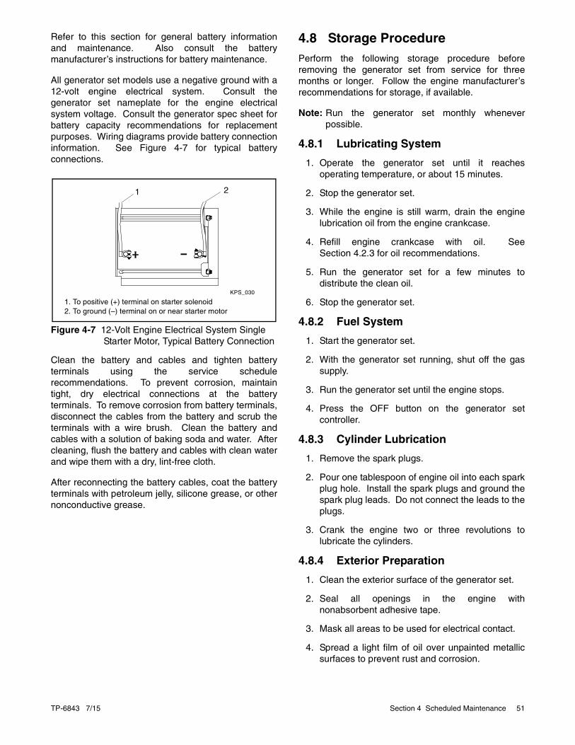
TP-6843 7/15 Section 4 Scheduled Maintenance 51
Refer to this section for general battery informationand maintenance. Also consult the batterymanufacturer’s instructions for battery maintenance.
All generator set models use a negative ground with a12-volt engine electrical system. Consult thegenerator set nameplate for the engine electricalsystem voltage. Consult the generator spec sheet forbattery capacity recommendations for replacementpurposes. Wiring diagrams provide battery connectioninformation. See Figure 4-7 for typical batteryconnections.
Figure 4-7
Figure 4-7 12-Volt Engine Electrical System Single Starter Motor, Typical Battery Connection
Clean the battery and cables and tighten batteryterminals using the service schedulerecommendations. To prevent corrosion, maintaintight, dry electrical connections at the batteryterminals. To remove corrosion from battery terminals,disconnect the cables from the battery and scrub theterminals with a wire brush. Clean the battery andcables with a solution of baking soda and water. Aftercleaning, flush the battery and cables with clean waterand wipe them with a dry, lint-free cloth.
After reconnecting the battery cables, coat the batteryterminals with petroleum jelly, silicone grease, or othernonconductive grease.
4.8 Storage ProcedurePerform the following storage procedure beforeremoving the generator set from service for threemonths or longer. Follow the engine manufacturer’srecommendations for storage, if available.
Note: Run the generator set monthly wheneverpossible.
4.8.1 Lubricating System
1. Operate the generator set until it reachesoperating temperature, or about 15 minutes.
2. Stop the generator set.
3. While the engine is still warm, drain the enginelubrication oil from the engine crankcase.
4. Refill engine crankcase with oil. SeeSection 4.2.3 for oil recommendations.
5. Run the generator set for a few minutes todistribute the clean oil.
6. Stop the generator set.
4.8.2 Fuel System
1. Start the generator set.
2. With the generator set running, shut off the gassupply.
3. Run the generator set until the engine stops.
4. Press the OFF button on the generator setcontroller.
4.8.3 Cylinder Lubrication
1. Remove the spark plugs.
2. Pour one tablespoon of engine oil into each sparkplug hole. Install the spark plugs and ground thespark plug leads. Do not connect the leads to theplugs.
3. Crank the engine two or three revolutions tolubricate the cylinders.
4.8.4 Exterior Preparation
1. Clean the exterior surface of the generator set.
2. Seal all openings in the engine withnonabsorbent adhesive tape.
3. Mask all areas to be used for electrical contact.
4. Spread a light film of oil over unpainted metallicsurfaces to prevent rust and corrosion.
KPS_030
1 2
1. To positive (+) terminal on starter solenoid2. To ground (–) terminal on or near starter motor

52 Section 4 Scheduled Maintenance TP-6843 7/15
4.8.5 Battery
Perform battery storage last.
1. Press the OFF button on the generator setcontroller.
2. Disconnect the battery, negative (–) lead first.
3. Clean the battery.
4. Place the battery in a warm, dry location.
5. Connect the battery to a float/equalize batterycharger, or charge the battery monthly using atrickle charger. Follow the battery chargermanufacturer’s recommendations.
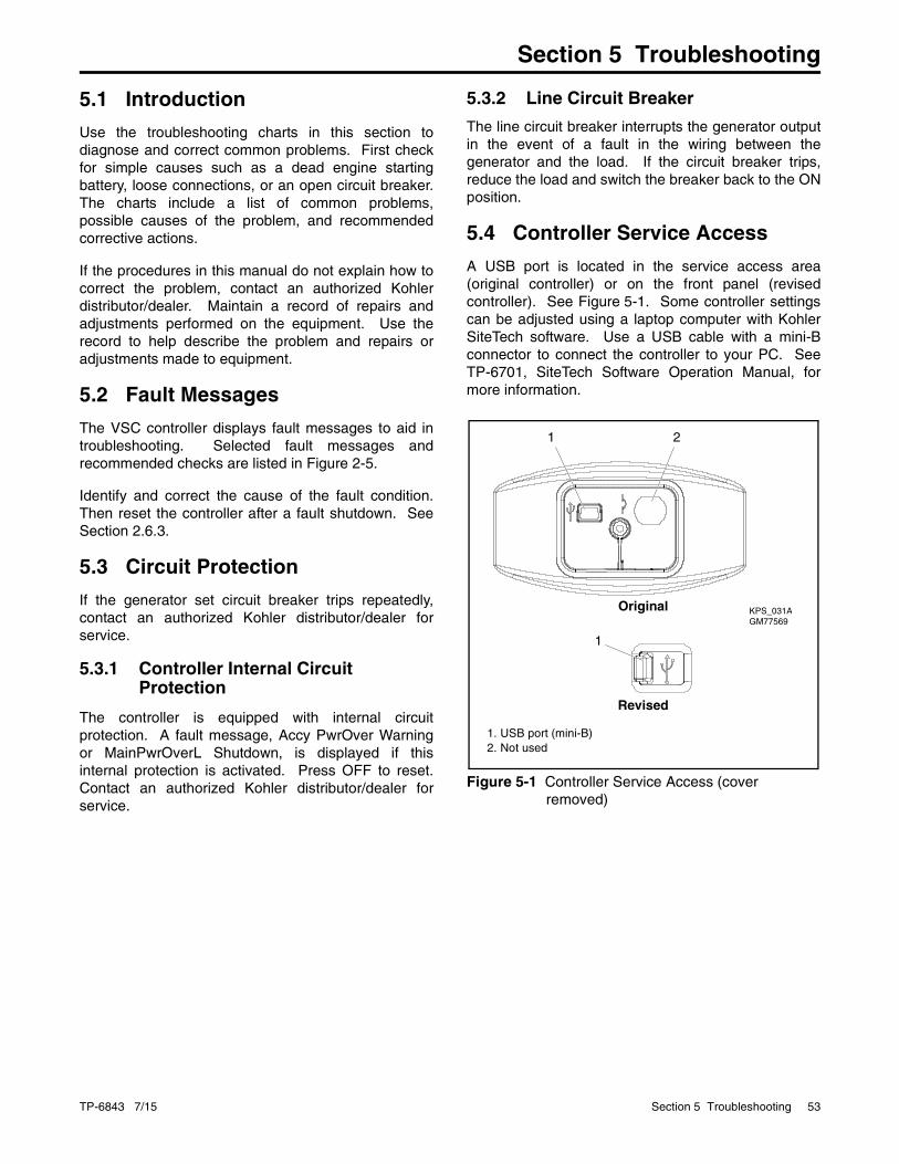
TP-6843 7/15 Section 5 Troubleshooting 53
Section 5 Troubleshooting
5.1 Introduction
Use the troubleshooting charts in this section todiagnose and correct common problems. First checkfor simple causes such as a dead engine startingbattery, loose connections, or an open circuit breaker.The charts include a list of common problems,possible causes of the problem, and recommendedcorrective actions.
If the procedures in this manual do not explain how tocorrect the problem, contact an authorized Kohlerdistributor/dealer. Maintain a record of repairs andadjustments performed on the equipment. Use therecord to help describe the problem and repairs oradjustments made to equipment.
5.2 Fault Messages
The VSC controller displays fault messages to aid introubleshooting. Selected fault messages andrecommended checks are listed in Figure 2-5.
Identify and correct the cause of the fault condition.Then reset the controller after a fault shutdown. SeeSection 2.6.3.
5.3 Circuit Protection
If the generator set circuit breaker trips repeatedly,contact an authorized Kohler distributor/dealer forservice.
5.3.1 Controller Internal Circuit Protection
The controller is equipped with internal circuitprotection. A fault message, Accy PwrOver Warningor MainPwrOverL Shutdown, is displayed if thisinternal protection is activated. Press OFF to reset.Contact an authorized Kohler distributor/dealer forservice.
5.3.2 Line Circuit Breaker
The line circuit breaker interrupts the generator outputin the event of a fault in the wiring between thegenerator and the load. If the circuit breaker trips,reduce the load and switch the breaker back to the ONposition.
5.4 Controller Service Access
A USB port is located in the service access area(original controller) or on the front panel (revisedcontroller). See Figure 5-1. Some controller settingscan be adjusted using a laptop computer with KohlerSiteTech software. Use a USB cable with a mini-Bconnector to connect the controller to your PC. SeeTP-6701, SiteTech Software Operation Manual, formore information.
Figure 5-1
Figure 5-1 Controller Service Access (cover removed)
KPS_031AGM77569
1 2
1
1. USB port (mini-B)2. Not used
Original
Revised
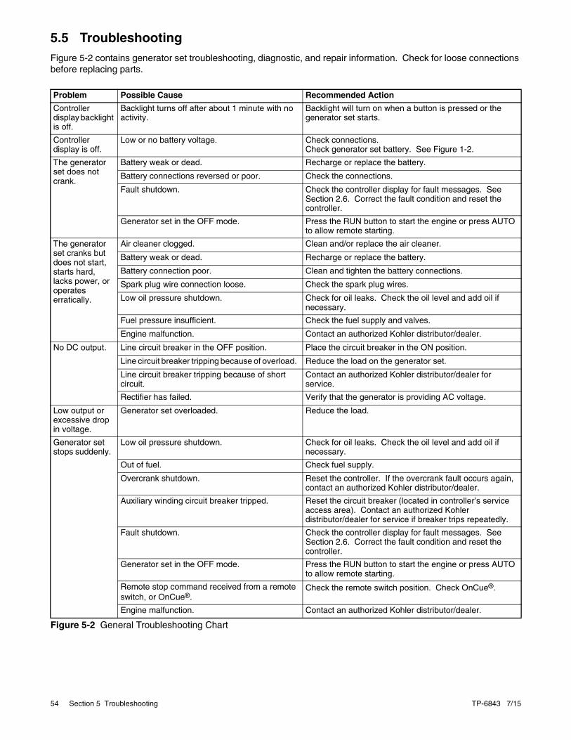
54 Section 5 Troubleshooting TP-6843 7/15
5.5 TroubleshootingFigure 5-2 contains generator set troubleshooting, diagnostic, and repair information. Check for loose connections before replacing parts.
Figure 5-2
Figure 5-2 General Troubleshooting Chart
Problem Possible Cause Recommended Action
Controller display backlight is off.
Backlight turns off after about 1 minute with no activity.
Backlight will turn on when a button is pressed or the generator set starts.
Controller display is off.
Low or no battery voltage. Check connections. Check generator set battery. See Figure 1-2.
The generator set does not crank.
Battery weak or dead. Recharge or replace the battery.
Battery connections reversed or poor. Check the connections.
Fault shutdown. Check the controller display for fault messages. See Section 2.6. Correct the fault condition and reset the controller.
Generator set in the OFF mode. Press the RUN button to start the engine or press AUTO to allow remote starting.
The generator set cranks but does not start, starts hard, lacks power, or operates erratically.
Air cleaner clogged. Clean and/or replace the air cleaner.
Battery weak or dead. Recharge or replace the battery.
Battery connection poor. Clean and tighten the battery connections.
Spark plug wire connection loose. Check the spark plug wires.
Low oil pressure shutdown. Check for oil leaks. Check the oil level and add oil if necessary.
Fuel pressure insufficient. Check the fuel supply and valves.
Engine malfunction. Contact an authorized Kohler distributor/dealer.
No DC output. Line circuit breaker in the OFF position. Place the circuit breaker in the ON position.
Line circuit breaker tripping because of overload. Reduce the load on the generator set.
Line circuit breaker tripping because of short circuit.
Contact an authorized Kohler distributor/dealer for service.
Rectifier has failed. Verify that the generator is providing AC voltage.
Low output or excessive drop in voltage.
Generator set overloaded. Reduce the load.
Generator set stops suddenly.
Low oil pressure shutdown. Check for oil leaks. Check the oil level and add oil if necessary.
Out of fuel. Check fuel supply.
Overcrank shutdown. Reset the controller. If the overcrank fault occurs again, contact an authorized Kohler distributor/dealer.
Auxiliary winding circuit breaker tripped. Reset the circuit breaker (located in controller’s service access area). Contact an authorized Kohler distributor/dealer for service if breaker trips repeatedly.
Fault shutdown. Check the controller display for fault messages. See Section 2.6. Correct the fault condition and reset the controller.
Generator set in the OFF mode. Press the RUN button to start the engine or press AUTO to allow remote starting.
Remote stop command received from a remote switch, or OnCue®.
Check the remote switch position. Check OnCue®.
Engine malfunction. Contact an authorized Kohler distributor/dealer.
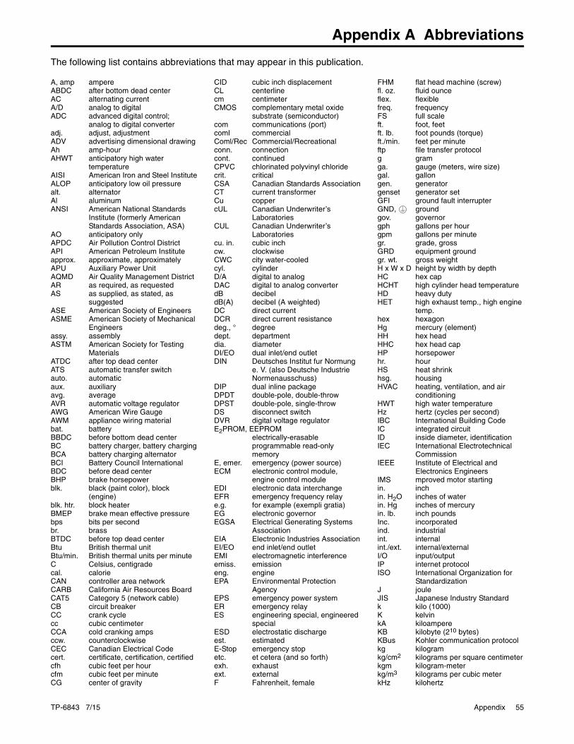
TP-6843 7/15 Appendix 55
Appendix A Abbreviations
The following list contains abbreviations that may appear in this publication.
A, amp ampereABDC after bottom dead centerAC alternating currentA/D analog to digitalADC advanced digital control;
analog to digital converteradj. adjust, adjustmentADV advertising dimensional drawingAh amp-hourAHWT anticipatory high water
temperatureAISI American Iron and Steel InstituteALOP anticipatory low oil pressurealt. alternatorAl aluminumANSI American National Standards
Institute (formerly American Standards Association, ASA)
AO anticipatory onlyAPDC Air Pollution Control DistrictAPI American Petroleum Instituteapprox. approximate, approximatelyAPU Auxiliary Power UnitAQMD Air Quality Management DistrictAR as required, as requestedAS as supplied, as stated, as
suggestedASE American Society of EngineersASME American Society of Mechanical
Engineersassy. assemblyASTM American Society for Testing
MaterialsATDC after top dead centerATS automatic transfer switchauto. automaticaux. auxiliaryavg. averageAVR automatic voltage regulatorAWG American Wire GaugeAWM appliance wiring materialbat. batteryBBDC before bottom dead centerBC battery charger, battery chargingBCA battery charging alternatorBCI Battery Council InternationalBDC before dead centerBHP brake horsepowerblk. black (paint color), block
(engine)blk. htr. block heaterBMEP brake mean effective pressurebps bits per secondbr. brassBTDC before top dead centerBtu British thermal unitBtu/min. British thermal units per minuteC Celsius, centigradecal. calorieCAN controller area networkCARB California Air Resources BoardCAT5 Category 5 (network cable)CB circuit breakerCC crank cyclecc cubic centimeterCCA cold cranking ampsccw. counterclockwiseCEC Canadian Electrical Codecert. certificate, certification, certifiedcfh cubic feet per hourcfm cubic feet per minuteCG center of gravity
CID cubic inch displacementCL centerlinecm centimeterCMOS complementary metal oxide
substrate (semiconductor)com communications (port)coml commercialComl/Rec Commercial/Recreationalconn. connectioncont. continuedCPVC chlorinated polyvinyl chloridecrit. criticalCSA Canadian Standards AssociationCT current transformerCu coppercUL Canadian Underwriter’s
LaboratoriesCUL Canadian Underwriter’s
Laboratoriescu. in. cubic inchcw. clockwiseCWC city water-cooledcyl. cylinderD/A digital to analogDAC digital to analog converterdB decibeldB(A) decibel (A weighted)DC direct currentDCR direct current resistancedeg., ° degreedept. departmentdia. diameterDI/EO dual inlet/end outletDIN Deutsches Institut fur Normung
e. V. (also Deutsche Industrie Normenausschuss)
DIP dual inline packageDPDT double-pole, double-throwDPST double-pole, single-throwDS disconnect switchDVR digital voltage regulatorE2PROM, EEPROM
electrically-erasableprogrammable read-onlymemory
E, emer. emergency (power source)ECM electronic control module,
engine control moduleEDI electronic data interchangeEFR emergency frequency relaye.g. for example (exempli gratia)EG electronic governorEGSA Electrical Generating Systems
AssociationEIA Electronic Industries AssociationEI/EO end inlet/end outletEMI electromagnetic interferenceemiss. emissioneng. engineEPA Environmental Protection
AgencyEPS emergency power systemER emergency relayES engineering special, engineered
specialESD electrostatic dischargeest. estimatedE-Stop emergency stopetc. et cetera (and so forth)exh. exhaustext. externalF Fahrenheit, female
FHM flat head machine (screw)fl. oz. fluid ounceflex. flexiblefreq. frequencyFS full scaleft. foot, feetft. lb. foot pounds (torque)ft./min. feet per minuteftp file transfer protocolg gramga. gauge (meters, wire size)gal. gallongen. generatorgenset generator setGFI ground fault interrupterGND, groundgov. governorgph gallons per hourgpm gallons per minutegr. grade, grossGRD equipment groundgr. wt. gross weightH x W x D height by width by depthHC hex capHCHT high cylinder head temperatureHD heavy dutyHET high exhaust temp., high engine
temp.hex hexagonHg mercury (element)HH hex headHHC hex head capHP horsepowerhr. hourHS heat shrinkhsg. housingHVAC heating, ventilation, and air
conditioningHWT high water temperatureHz hertz (cycles per second)IBC International Building CodeIC integrated circuitID inside diameter, identificationIEC International Electrotechnical
CommissionIEEE Institute of Electrical and
Electronics EngineersIMS mproved motor startingin. inchin. H2O inches of waterin. Hg inches of mercuryin. lb. inch poundsInc. incorporatedind. industrialint. internalint./ext. internal/externalI/O input/outputIP internet protocolISO International Organization for
StandardizationJ jouleJIS Japanese Industry Standardk kilo (1000)K kelvinkA kiloampereKB kilobyte (210 bytes)KBus Kohler communication protocolkg kilogramkg/cm2 kilograms per square centimeterkgm kilogram-meterkg/m3 kilograms per cubic meterkHz kilohertz

56 Appendix TP-6843 7/15
kJ kilojoulekm kilometerkOhm, kΩ kilo-ohmkPa kilopascalkph kilometers per hourkV kilovoltkVA kilovolt amperekVAR kilovolt ampere reactivekW kilowattkWh kilowatt-hourkWm kilowatt mechanicalkWth kilowatt-thermalL literLAN local area networkL x W x H length by width by heightlb. pound, poundslbm/ft3 pounds mass per cubic feetLCB line circuit breakerLCD liquid crystal displayLED light emitting diodeLph liters per hourLpm liters per minuteLOP low oil pressureLP liquefied petroleumLPG liquefied petroleum gasLS left sideLwa sound power level, A weightedLWL low water levelLWT low water temperaturem meter, milli (1/1000)M mega (106 when used with SI
units), malem3 cubic meterm3/hr. cubic meters per hourm3/min. cubic meters per minutemA milliampereman. manualmax. maximumMB megabyte (220 bytes)MCCB molded-case circuit breakerMCM one thousand circular milsmeggar megohmmeterMHz megahertzmi. milemil one one-thousandth of an inchmin. minimum, minutemisc. miscellaneousMJ megajoulemJ millijoulemm millimetermOhm, mΩ milliohmMOhm, MΩ megohmMOV metal oxide varistorMPa megapascalmpg miles per gallonmph miles per hourMS military standardms millisecondm/sec. meters per secondmtg. mountingMTU Motoren-und Turbinen-UnionMW megawattmW milliwattμF microfaradN, norm. normal (power source)NA not available, not applicablenat. gas natural gasNBS National Bureau of StandardsNC normally closedNEC National Electrical CodeNEMA National Electrical
Manufacturers AssociationNFPA National Fire Protection
AssociationNm newton meterNO normally openno., nos. number, numbersNPS National Pipe, Straight
NPSC National Pipe, Straight-couplingNPT National Standard taper pipe
thread per general useNPTF National Pipe, Taper-FineNR not required, normal relayns nanosecondOC overcrankOD outside diameterOEM original equipment manufacturerOF overfrequencyopt. option, optionalOS oversize, overspeedOSHA Occupational Safety and Health
AdministrationOV overvoltageoz. ouncep., pp. page, pagesPC personal computerPCB printed circuit boardpF pic ofaradPF power factorph., Ø phasePHC Phillips head Crimptite (screw)PHH Phillips hex head (screw)PHM pan head machine (screw)PLC programmable logic controlPMG permanent magnet generatorpot potentiometer, potentialppm parts per millionPROM programmable read-only
memorypsi pounds per square inchpsig pounds per square inch gaugept. pintPTC positive temperature coefficientPTO power takeoffPVC polyvinyl chlorideqt. quart, quartsqty. quantityR replacement (emergency) power
sourcerad. radiator, radiusRAM random access memoryRBUS RS-485 proprietary
communicationsRDO relay driver outputref. referencerem. remoteRes/Coml Residential/CommercialRFI radio frequency interferenceRH round headRHM round head machine (screw)rly. relayrms root mean squarernd. roundRO read onlyROM read only memoryrot. rotate, rotatingrpm revolutions per minuteRS right sideRTDs Resistance Temperature
DetectorsRTU remote terminal unitRTV room temperature vulcanizationRW read/writeSAE Society of Automotive Engineersscfm standard cubic feet per minuteSCR silicon controlled rectifiers, sec. secondSI Systeme international d’unites,
International System of UnitsSI/EO side in/end outsil. silencerSMTP simple mail transfer protocolSN serial numberSNMP simple network management
protocolSPDT single-pole, double-throw
SPST single-pole, single-throwspec specificationspecs specification(s)sq. squaresq. cm square centimetersq. in. square inchSMS short message serviceSS stainless steelstd. standardstl. steeltach. tachometerTB terminal blockTCP transmission control protocolTD time delayTDC top dead centerTDEC time delay engine cooldownTDEN time delay emergency to normalTDES time delay engine startTDNE time delay normal to emergencyTDOE time delay off to emergencyTDON time delay off to normaltemp. temperatureterm. terminalTHD total harmonic distortionTIF telephone influence factortol. toleranceturbo. turbochargertyp. typical (same in multiple
locations)UF underfrequencyUHF ultrahigh frequencyUIF user interfaceUL Underwriter’s Laboratories, Inc.UNC unified coarse thread (was NC)UNF unified fine thread (was NF)univ. universalURL uniform resource locator (web
address)US undersize, underspeedUV ultraviolet, undervoltageV voltVAC volts alternating currentVAR voltampere reactiveVDC volts direct currentVFD vacuum fluorescent displayVGA video graphics adapterVHF very high frequencyW wattWCR withstand and closing ratingw/ withWO write onlyw/o withoutwt. weightxfmr transformer

TP-6843 7/15 Appendix 57
Notes

KOHLER CO. Kohler, Wisconsin 53044Phone 920-457-4441, Fax 920-459-1646
Kohler Power SystemsAsia Pacific Headquarters7 Jurong Pier RoadSingapore 619159Phone (65) 6264-6422, Fax (65) 6264-6455
For the nearest KOHLER authorized installation, service, and sales dealer in the US and Canada:Call 1-800-544-2444 or visitKOHLERPower.com
TP-6843 7/15b© 2012, 2013, 2015 by Kohler Co. All rights reserved.