Embed Size (px)
Citation preview
S T E E L J O I S T D E S I G N G U I D E
“ T H E S T R E N G T H T O S U P P O R T Y O U ”
ARIZONA PhoenixPhone: 602-447-0204Fax: 602-447-3017
CALIFORNIA ColtonPhone: 909-824-9717Fax:909-824-5760StocktonPhone: 209-547-9066Fax: 209-547-9128
COLORADO DenverPhone: 303-289-4092Fax: 303-289-4157
FLORIDA MiamiPhone: 305-652-5423Fax: 305-652-5344WildwoodPhone: 352-748-7200Fax: 352-748-7252
GEORGIA AtlantaPhone: 404-696-7700Fax: 404-696-7797
HAWAII KapoleiPhone: 808-682-5747Fax: 808-682-2928
INDIANA HammondPhone: 219-931-3741Fax: 219-937-6804
OHIO HicksvillePhone: 419-542-7781Fax: 419-542-7816WarrenPhone: 330-372-5564Fax: 330-372-4055
KANSAS LenexaPhone: 913-599-2026Fax: 913-599-2028
MARYLAND BaltimorePhone: 410-477-8700Fax: 410-477-3536
MASSACHUSETTS LunenburgPhone: 978-342-9742Fax: 978-342-9765
NEW JERSEY East BrunswickPhone: 732-432-0892Fax: 732-432-0841
SOUTH CAROLINA Rock HillPhone: 803-324-4140Fax: 803-324-7090
TEXAS HutchinsPhone: 972-225-1100Fax: 972-225-9032
WASHINGTON RentonPhone: 425-251-1497Fax: 425-251-3161
Dietrich Metal Framing500 Grant Street / Suite 2226
Pittsburgh, PA 15219Telephone: (412) 281-2805www.steelfloorjoist.com
e-mail: [email protected]
TradeReady® & Dietrich Metal Framing Copyright © 2002
68/02 DIETRICHTradeReady® Design Guide

S T E E L J O I S T D E S I G N G U I D E
“ T H E S T R E N G T H T O S U P P O R T Y O U ”
A Glossary of terms:
Blocking: Solid block or piece of material placed between structural members to provide lateral bracing as in bridging and/or edge support for sheathing.
Bridging: Cross bracing or blocking placed between joists to provide lateral support.
C-Shape: A basic cold-formed steel shape used for structural framing members (such as joists). The name comes from the member’s "C" shaped cross-sectional configuration consisting of a web, flange and lip. It is also called a "C-section". Web depth measurements are taken to the outside of the flanges. Flange width measurements also use outside dimensions.
Clip Angle: An L-shaped short piece of metal (normally with a 90-degree bend) typically used for connections
Flange: The part of a C-Shape or track that is perpendicular to the web.
Flat Strap: Sheet steel cut to a specified width without any bends. Typically used for bracing andtransferring loads by tension.
Floor Joist: A horizontal structural framing member that supports floor loads.
Hard Side of Joist: Plane at joist along the web side opposite the C opening. The outside of the C.
Header: A horizontal built-up structural-framing member used for floor openings to transfer loads to adjacent framing members.
Joist Orientation: To assure that the holes line up across a given area of the foundation, the joist needs to be installed from the same beginning point.
Lip: The part of a C-Shape that extends from the flange at the open end. The lip increases the strength characteristics of the member and acts as a stiffener to the flange.
Loads, Live and Dead: Dead loads are the weight of the walls, partitions, framing, floors, ceilings, roofs, and all other permanent construction entering into and becoming a part of a building. Live loads are transient and sustained loads usually created by people and furnishing, respectively.
Multiple Span: The span made by a continuous member having intermediate supports.
Open side of Joist: Plane of joist along the flange of the open side of the "C".
Span: The clear horizontal distance between bearing supports.
Punchout: A hole or opening in the web of a steel-framing member allowing for the installation of plumbing, electrical, and other utility installation. A punchout may be made during the manufacturing process or in the field with a hand punch, hole saw, or other suitable tool.
Single Span: The span made by one continuous structural member without any intermediate supports.
Span Direction: The direction the joist lays across the foundation.
Structural Sheathing: The covering (e.g., plywood or oriented strand board) used directly over structuralmembers (e.g., joists) to distribute loads, provide lateral stability to the framing members, and generally strengthen the assembly.
Web: The part of a C-Shape or track that connects the two flanges.
Web Crippling: The localized permanent (inelastic) deformation of the web member subjected toconcentrated load or reaction at bearing supports.
Web Stiffener: Additional material that is attached to the web to strengthen the member against webcrippling. Also called a bearing or transverse stiffener.

i
S T E E L J O I S T D E S I G N G U I D ES T E E L J O I S T D E S I G N G U I D E
“ T H E S T R E N G T H T O S U P P O R T Y O U ”
Design Guidefor the
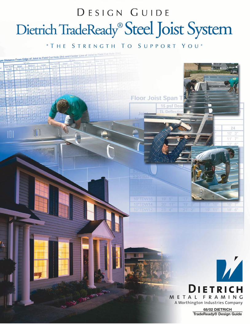
Dietrich TradeReady®
Steel Joist System*
Disclaimer:The technical information contained in this Guide was prepared to assist professional engineers and architects in theuse of the Dietrich TradeReady® Steel Joist System and should be used only with the guidance and judgement of sucharchitect or engineer.
THE TECHNICAL INFORMATION CONTAINED HEREIN IS SUPPLIED SOLELY TO ASSIST IN THESELECTION AND/OR ANALYSIS OF DIETRICH METAL FRAMING PRODUCTS AND NOT FORCONSTRUCTION PURPOSES. DIETRICH METAL FRAMING HEREBY DISCLAIMS ANY WARRANTYOR REPRESENTATION EXPRESS OR IMPLIED WITH RESPECT TO THE USE OF THE INFORMATIONCONTAINED HEREIN OR ITS USEFULNESS FOR A PARTICULAR PURPOSE OR APPLICATION.DIETRICH METAL FRAMING SHALL IN NO WAY BE DEEMED TO ASSUME ANY PROFESSIONALRESPONSIBILITY AND HEREBY DISCLAIMS ANY AND ALL SUCH LIABILITY OR OBLIGATION.
*TradeReady® Steel Joist System (U.S. Patent# 6,301,854 and other Patents Pending)
Job Site Safety
Always follow OSHA guidelines and safety requirements when they are applicable.
• DO NOT walk on unbraced joist.Injury may result.
• DO NOT load floor decking before sheathing and bracing is complete.Place loads only over load bearing members.
• Wear work gloves to protect hands from cuts and injuries when working with steel.
• Safety goggles are recommended when cutting steel or when fastening members.
• Cutting and welding galvanized steel can produce harmful fumes that can be hazardous to health and causeirritation to respiratory system. Make sure all cutting and welding is done in a well-ventilated area.
• Use caution when working with steel when wet. Steel members may be slippery and cause injuries if notproperly handled.
Storage and Handling
Proper storage and handling will ensure the structural integrity of steel framing members and components
1. TradeReady® Steel joist bundles should be stored level.
2. DO NOT open bundles until time of installation. Use care when handling bundles and individualcomponents to prevent injury to handlers or damage by forklift or crane.
3. Twisting of steel joists, or applying loads to the joist when flat can damage the joist.Damaged steel joists should not be used.
4. Never handle steel joist flat. Beginning with the unloading process, and throughout all phases ofconstruction, care must be taken to avoid lateral and torsional bending of joists, which can cause damage to the steel joists.
5.4
ii 5.3
NO
TE
S
S T E E L J O I S T D E S I G N G U I D ES T E E L J O I S T D E S I G N G U I D E
“ T H E S T R E N G T H T O S U P P O R T Y O U ”“ T H E S T R E N G T H T O S U P P O R T Y O U ”
TABLE OF CONTENTS
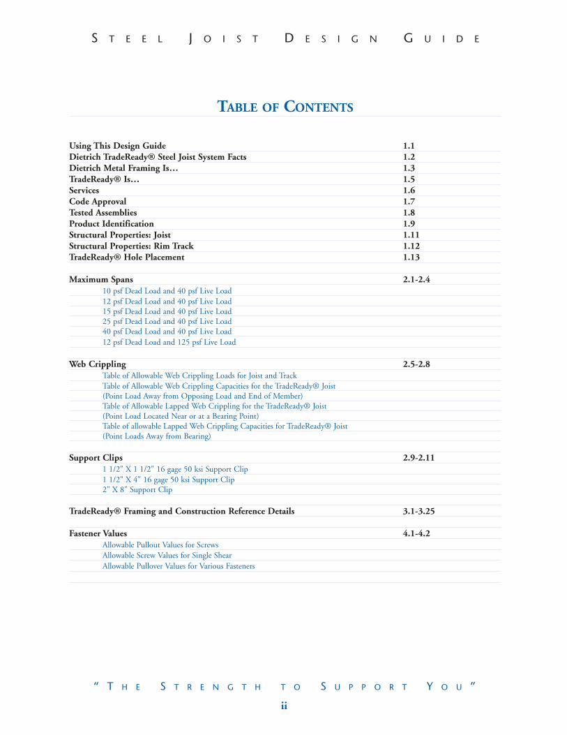
Using This Design Guide 1.1Dietrich TradeReady® Steel Joist System Facts 1.2Dietrich Metal Framing Is… 1.3TradeReady® Is… 1.5Services 1.6Code Approval 1.7Tested Assemblies 1.8Product Identification 1.9Structural Properties: Joist 1.11Structural Properties: Rim Track 1.12TradeReady® Hole Placement 1.13
Maximum Spans 2.1-2.410 psf Dead Load and 40 psf Live Load12 psf Dead Load and 40 psf Live Load15 psf Dead Load and 40 psf Live Load25 psf Dead Load and 40 psf Live Load40 psf Dead Load and 40 psf Live Load12 psf Dead Load and 125 psf Live Load
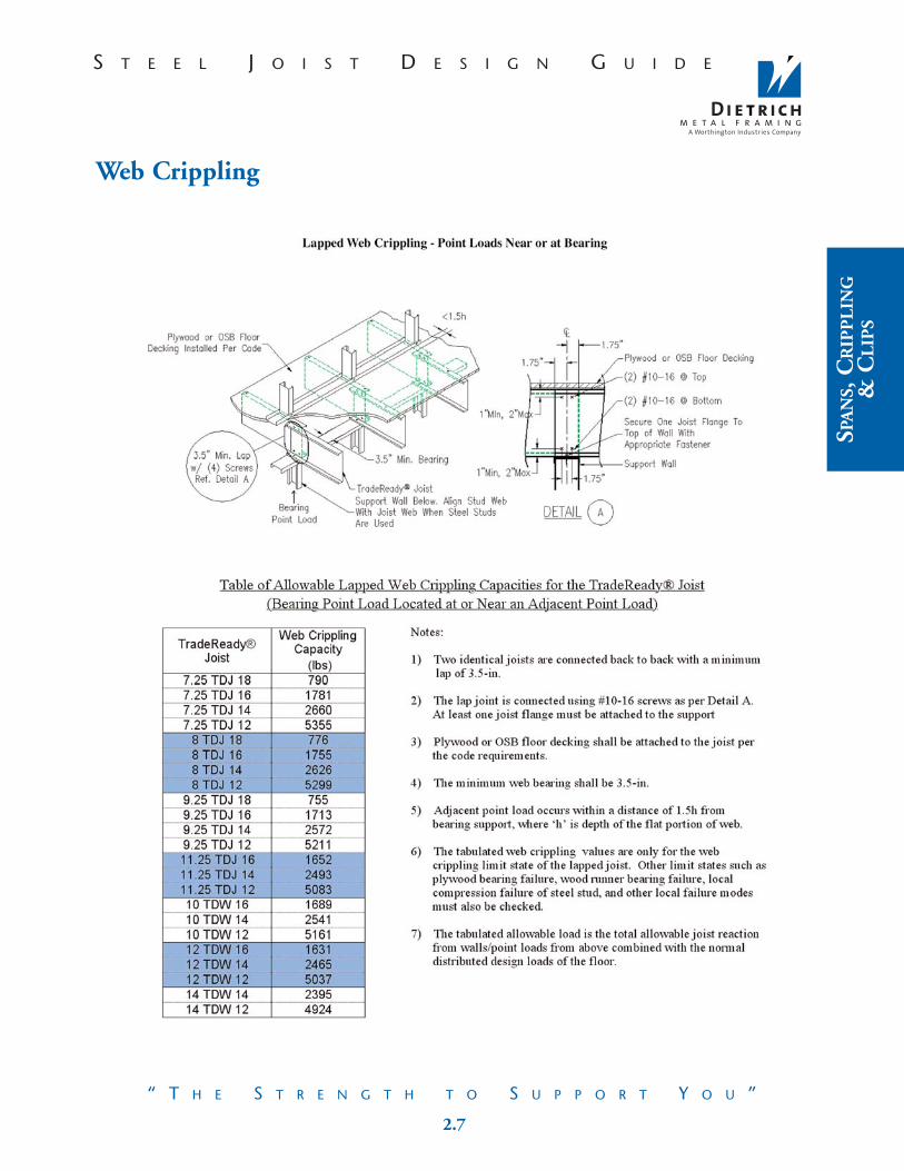
Web Crippling 2.5-2.8Table of Allowable Web Crippling Loads for Joist and TrackTable of Allowable Web Crippling Capacities for the TradeReady® Joist (Point Load Away from Opposing Load and End of Member)Table of Allowable Lapped Web Crippling for the TradeReady® Joist (Point Load Located Near or at a Bearing Point)Table of allowable Lapped Web Crippling Capacities for TradeReady® Joist(Point Loads Away from Bearing)
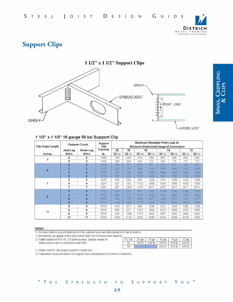
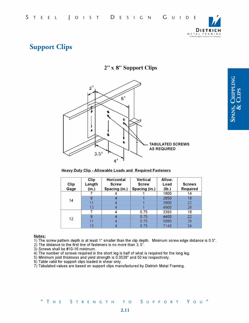
Support Clips 2.9-2.111 1/2" X 1 1/2" 16 gage 50 ksi Support Clip1 1/2" X 4" 16 gage 50 ksi Support Clip2" X 8" Support Clip
TradeReady® Framing and Construction Reference Details 3.1-3.25
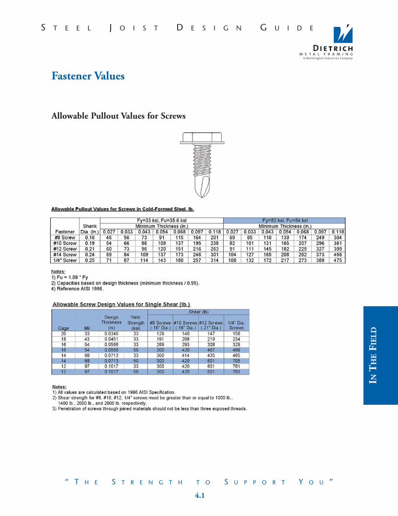
Fastener Values 4.1-4.2Allowable Pullout Values for ScrewsAllowable Screw Values for Single ShearAllowable Pullover Values for Various Fasteners
3.0 MATERIAL NOTES
3.01 Properties used in this Design Guide are those published by Dietrich Metal Framing.No other material may be utilized.
3.02 All members 16 gage and heavier shall be formed from steel corresponding to a type listed in the A.I.S.I. "Specification for the Design of Cold-Formed Steel Structural Members", with a minimum yield strength of 50 ksi unless specifically noted otherwise.
3.03 All 18 gage and lighter members shall be formed from steel corresponding to a type listed in the A.I.S.I. "Specification for the Design of Cold-Formed Steel Structural Members" with a minimum yield strength of 33 ksi unless specifically noted otherwise.
3.04 Structural properties and capacities of steel framing components shall be in accordance with the A.I.S.I. "Specification for the Design of Cold-Formed Steel Structural Members".
3.05 All structural framing products shall be formed from steel possessing a coating corresponding to the minimum requirements of ASTM C955.
3.06 When Dietrich TradeReady® steel joist or track are to be used for a beam, girder, or header application,joist and track members shall have unpunched webs unless otherwise approved. It is the responsibility of the contractor to specify unpunched members when ordering materials.
3.07 All support clips and clip angles are 50 ksi., unless noted otherwise.

5.2 iii
S T E E L J O I S T D E S I G N G U I D ES T E E L J O I S T D E S I G N G U I D E
“ T H E S T R E N G T H T O S U P P O R T Y O U ”“ T H E S T R E N G T H T O S U P P O R T Y O U ”
TABLE OF CONTENTS (CONTINUED)
Field Cut Holes 4.3-4.610-40 loads @ 12" and 16" o.c.10-40 loads @ 19.2" and 24" o.c.40-40 loads @ 12" and 16" o.c.40-40 loads @ 19.2" and 24" o.c.
In the Field 4.7Tools of the TradeReady® 4.8General Notes 5.1Installation Notes 5.2Material Notes 5.3Job Site Safety 5.4Storage and Handling 5.4Glossary of Terms 5.5
2.0 INSTALLATION NOTES
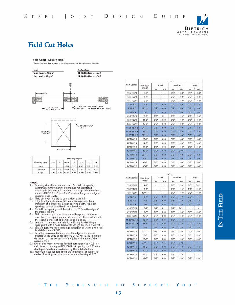
2.01 All framing components shall be cut squarely for attachment to perpendicular members or as required on angularfit against abutting members. Members shall be held positively in place until properly fastened.
2.02 Temporary bracing shall be provided and remain in place until the structure is completely stabilized. Design of temporary bracing is not the responsibility of Dietrich Metal Framing.
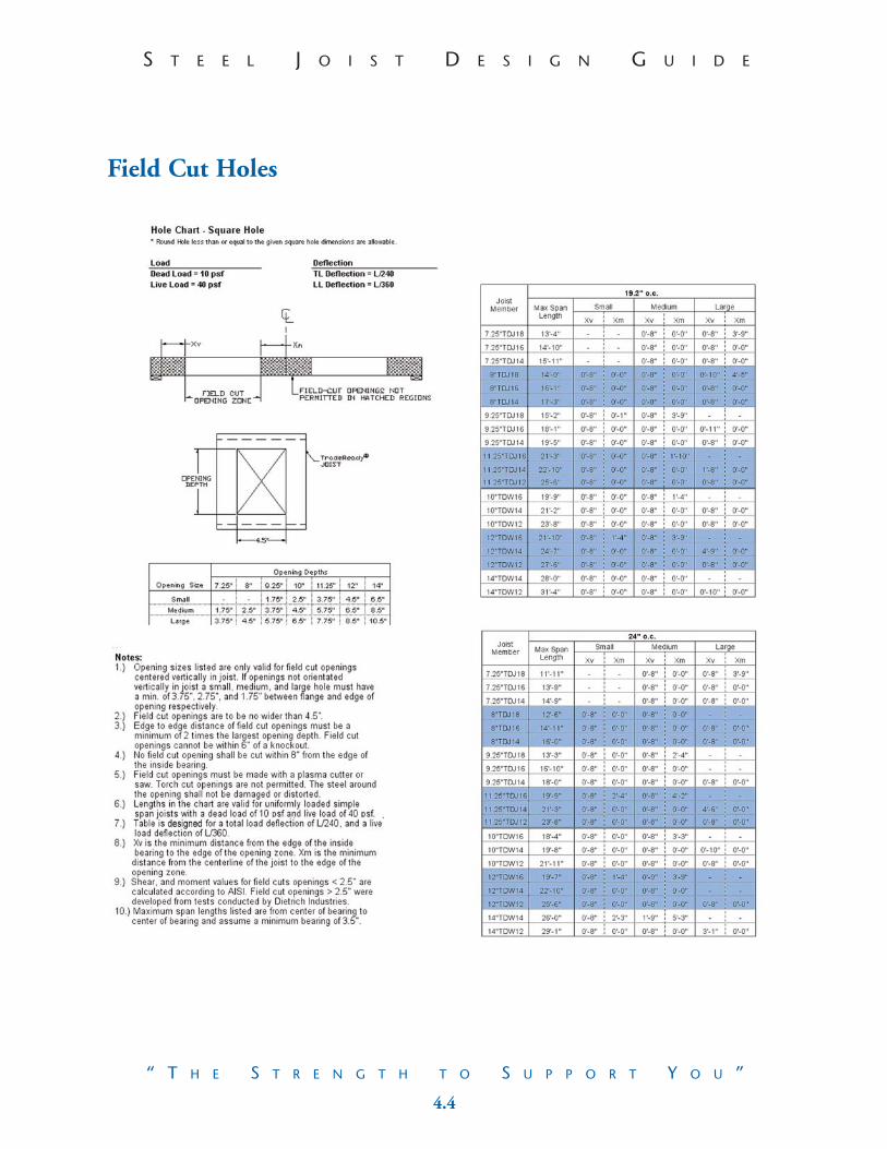
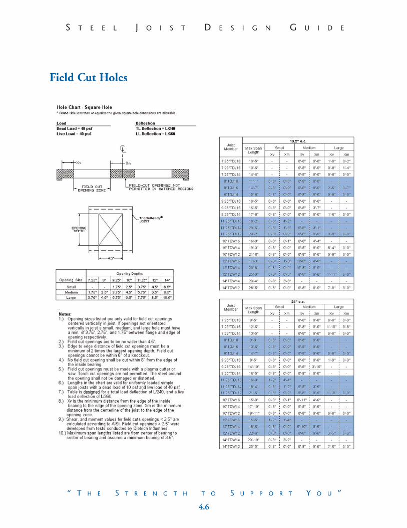
2.03 All field cutting of members must be done by sawing, plasma cutting or shearing. Torch cutting of cold formed members is unacceptable.
2.04 It is the responsibility of the contractor to assemble the floor system in such a way that the knockouts align for mechanical runs and to ensure that knockouts do not occur within 6" of a bearing point due to field cutting.
2.05 No splices in studs, joists, or other load carrying members may be made without prior engineering review and specific details for any such splice(s).
2.06 If additional holes are required beyond the scope of the “Field Cut Holes Table” in the floor system, contact a licensed professional engineer for guidance before cutting.
2.07 Mechanical bridging, spaced at the intervals described herein, shall be installed prior to the attachment of sheathing materials.
2.08 Installation of sheathing, wallboard or any other collateral material shall be performed in accordance with the product manufacturer’s specifications, the current ASTM standard and/or guidelines outlined in the contract documents.
2.09 For all tracks used in composite members such as beams and girders, the track must be installed as a single piece, no splicing permitted, unless otherwise noted.
2.10 When support clips are used to attach a component to the primary structure, the support clip is to be fastened tothe primary structure first. Then, the component should be brought to bear on the structure, and then fastened to the support clip.
2.11 Support clips/hangers shall be installed per manufacturers instructions.
1.1 5.1
NO
TE
S
S T E E L J O I S T D E S I G N G U I D ES T E E L J O I S T D E S I G N G U I D E
“ T H E S T R E N G T H T O S U P P O R T Y O U ”“ T H E S T R E N G T H T O S U P P O R T Y O U ”
The technical information contained in this Guide was prepared to assist professional engineers and architects in theuse of the Dietrich TradeReady® Steel Joist System and should be used only with the guidance and judgement of sucharchitect or engineer.
Using This Design Guide
1. It is the responsibility of the user of the Design Guide for the DietrichTradeReady® Steel Joist System to identify:
Load conditionsLoad pathsBuildings general stabilityField Conditions
2. When designing a floor system, many factors may effect the end feelof the floor including:
Designed live and dead loads and deflection criteria.On center spacing of joist.Bridging and blocking.Floor sheathing type and size.Floor finish.Location of load bearing and non load bearing walls above and below.
3. Floor member selection may involve the following conditions for consideration:
Joist span.Joist web crippling.Joist attachment to girders or beams using Support clips.Rim and joist framing details.
4. Additional considerations may include:
TradeReady‚ rolled hole alignment and orientation.TradeReady‚ rolled hole access and field penetrations.
5. Value Engineering.
Often times the less expensive joist is a lighter gage joist combined with a taller web heightversus a heavier gage and shorter web height.
Excessive value engineering (choosing the least expensive member for every framing area) may hinder the ordering and framing process by creating too many custom parts and pieces for the construction process. Utilizing only one or two different joist sizes is recommended.
For more information please visit www.steelfloorjoist.com.
1.0 GENERAL NOTES
1.01 Contents of this Design Guide show the intended application of Dietrich Metal Framing TradeReady® Steel Joist framing components and accessories. Framing erector is to refer to the project contract documents for additional construction assembly requirements. The substitution of any other material deems this information null and void.
1.02 Details shown are for common and general applications. They are for design reference only. All conditions shall be field verified prior to erection.
1.03 The contents of this Design Guide are subject to the review and approval of the Owner’s Structural Engineer and Architect prior to erection. Material selections and connection details shown may differ from those shown in the contract documents. The framing erector should not order material before receiving shop drawing approval from the project officials.
1.04 Adequacy of the primary structure for loads imposed by the cold formed framing system is not the responsibility of Dietrich Metal Framing.
1.05 For specific requirements and warranty information on systems or materials connected and appurtenant to the cold-formed steel framing including windows, caulking and flashings, refer to manufacturer’s data.Dietrich Metal Framing assumes no responsibility for the proper construction or function of the total architectural assembly.
1.06 Conditions and or sections encircled may require special review by the project architect and/or structuralengineer. Additional project detail information and verification of conditions may be required.
1.07 The design of the cold-formed framing is performed in accordance with the AISI “Specification for the Design of Cold Formed Steel Structural Members”.
1.08 Framing analysis assumes that the sheathing is attached to each floor joist, solid block, and rim track. Framing analysis is limited to the uniform distribution of load to the joist and does not include review of the effects of local forces.
1.09 This Design Guide does not take precedence over the contract documents with regard to minimum yield strength, gage, web depth, flange width or stud spacing, unless approved by the Engineer of Record (E.O.R.).
1.10 Calculation and shop drawings included in this Design Guide do not take into consideration the overall stabilityof structure. It is the responsibility of the Structural Engineer of Record to design the shear strapping and/or determine the allowable resistance of the building diaphragm to maintain overall stability of the structure.
1.11 The information here in is an aid in the general construction of Dietrich Metal Framing’s TradeReady Steel Joist System and to facilitate the work that the framer, architect or the engineer of record must perform. They do not in any way imply the assumption of professional responsibility of the architect or of the engineer of record by Dietrich Metal Framing.
4.8 1.2
IMP
OR
TA
NT
INFO
RM
ATIO
N
S T E E L J O I S T D E S I G N G U I D ES T E E L J O I S T D E S I G N G U I D E
“ T H E S T R E N G T H T O S U P P O R T Y O U ”“ T H E S T R E N G T H T O S U P P O R T Y O U ”
Dietrich TradeReady® Steel Joist Facts
Code Compliant:Cold-Formed steel floor framing is approved in the International Building Code and InternationalResidential Code for One- and Two-Family Dwellings, section R505.
Ease of Installation:Light in weight, steel joists are easy to handle. Ordered cut to length, they reduce the need for a cutman and pre-punched holes nearly eliminate the need for making penetrations.
Consistent Quality:Steel is dimensionally stable and structurally consistent.Steel does not contain knots, twists or warps.
Light Weight:Steel has the highest strength to weight ratio of any building material and can weigh as much as40% less than corresponding wood members, reducing total building and seismic loads which mayreduce foundation and anchoring requirements.
Price Stability:The price of steel is stable and does not undergo erratic price fluctuations.
Design Flexibility:Steels superior strength allows designers to meet specific load requirements economically.
Termite and Pest Resistant:Steel framing members are impervious to termites and other wood destroying insects.
Fire Resistant:Light gage steel framing members are non-combustible.
Nationwide Distribution:Dietrich Metal Framing has nineteen manufacturing facilities strategically located throughoutthe continental United States and Hawaii.
TOOLS OF THE TRADE
Electric Shears: A hand held tool used to cut steel thicknesses up to 68-mils
Abrasive or Dry Cut Metal Blades: Used in a chop saw or circular saw for field cutting.
Plasma Cutter: Tool utilizing an electric arc for cutting steel members to length and for making penetration cuts without a pilot hole.
Screw Gun: A torque adjustable, clutch activated
screw gun operating from 0-2500 rpm’s.
Locking C-Clamps:Often used to hold steel pieces tight during fastening.
Collated Screw Gun:Auto feeding screw gun used for
attaching sheathing.
For specific tool information please visit www.steelfloorjoist.com
1.3 4.7
S T E E L J O I S T D E S I G N G U I D ES T E E L J O I S T D E S I G N G U I D E
“ T H E S T R E N G T H T O S U P P O R T Y O U ”“ T H E S T R E N G T H T O S U P P O R T Y O U ”
Dietrich Metal Framing is…Dietrich Metal Framing is an important segment of the Worthington Industries family of value-added, metals-relatedbusinesses. With 19 facilities in 15 states, Dietrich is the only metal framing manufacturer with national operations anddistribution. Dietrich is the largest metal framing manufacturer in the world.
The Worthington Industries PhilosophyThe Worthington Industries Philosophy is based on the Golden Rule - We treat our employees, customers, suppliersand shareholders as we would like to be treated. At Worthington Industries, we encourage our employees to join in theWorthington Philosophy by helping out in the communities where they live and work.
EARNINGS
• The first corporate goal for Worthington Industries is to earn money for its shareholders and increase the value of their investment.
• We believe that the best measurement of the accomplishment of our goal is consistent growth in earnings per share.
OUR GOLDEN RULE
• We treat our customers, employees, investors and suppliers, as we would like to be treated.
PEOPLE
• We are dedicated to the belief that people are our most important asset.
• We believe people respond to recognition, opportunity to grow and fair compensation.
• We believe that compensation should be directly related to job performance and therefore use incentives, profit sharing or otherwise, in every possible situation.
• From employees we expect an honest day’s work for an honest day’s pay.
• We believe in the philosophy of continued employment for all Worthington people.
• In filling job openings every effort is expended to find candidates within Worthington, its divisions or subsidiaries.
CUSTOMERS
• Without the customer and their need for our products and services we have nothing.
• We will exert every effort to see that the customer’s quality and service requirements are met.
• Once a commitment is made to a customer, every effort is made to fulfill that obligation.
SUPPLIERS
• We cannot operate profitably without those who supply the quality materials we need.
• We ask that suppliers be competitive in the marketplace with regard to quality, pricing, delivery and volume purchased.
• We are a loyal customer to suppliers who meet our quality and service requirements through all market conditions.
In The Field: Installing the Dietrich TradeReady® Steel Joist System
1. Check Material against cut list2. Check joist layout against plumbing and HVAC requirements3. Install TradeReady® Rim Track - Set first tab on layout,
subsequent rims are butted together continuing the layout.4. Build / install girders.5. Set joist across work area.
Note the joist orientation, holes should line up.
6. Install any required web stiffeners or squash blocks prior to setting joist as perplan when possible.
7. Rotate hard side of joist to tab and screw attach through pre-punched tab holes (Fig.1).8. Attach joist to intermediate bearing locations.9. Install temporary bracing as needed.10. Install blocking/bridging and solid blocking as required.11. Attach sub flooring – glue over joist, rim and blocking and screw attach
sheathing as per details
Fig 1: Rim Tab to Hard Side of Joist Only.
INT
HE
FIE
LD

4.6 1.4
IMP
OR
TA
NT
INFO
RM
ATIO
N
S T E E L J O I S T D E S I G N G U I D ES T E E L J O I S T D E S I G N G U I D E
“ T H E S T R E N G T H T O S U P P O R T Y O U ”“ T H E S T R E N G T H T O S U P P O R T Y O U ”
Dietrich Metal Framing is…
ORGANIZATION
• We believe in a divisionalized organizational structure with responsibility for performance resting with the head of each operation.
• All managers are given the operating latitude and authority to accomplish their responsibilities withinour corporate goals and objectives.
• In keeping with this philosophy, we do not create excessive corporate procedures. If procedures are necessary within a particular company operation, that manager creates them.
• We believe in a small corporate staff and support group to service the needs of our shareholdersand operating units as requested.
COMMUNICATION
• We communicate through every possible channel with our customers, employees, shareholders,suppliers and financial community.
CITIZENSHIP
• Worthington Industries practices good citizenship at all levels. We conduct our business in a professional and ethical manner.
• We encourage all our people to actively participate in community affairs.
• We support worthwhile community causes.
Field Cut Holes

1.5 4.5
S T E E L J O I S T D E S I G N G U I D ES T E E L J O I S T D E S I G N G U I D E
“ T H E S T R E N G T H T O S U P P O R T Y O U ”“ T H E S T R E N G T H T O S U P P O R T Y O U ”
TradeReady® is…
The TradeReady® products by Dietrich Metal Framing are more than componentsand pieces… TradeReady® is a philosophy!
Offering value added products is only the beginning. Next are our services. Going beyond simple design work and a knowledgeable sales staff, TradeReady® includes:
• The TradeReady® Steel Joist System: Joist, Rim Track, and Bridging.
• Complete Floor Design and Sizing.
• Field Technical Representatives assist you and answer questions before,during and after the building process.
• Comprehensive web site offering construction details, accessory products, tools and more. Visit us at: www.steelfloorjoist.com.
The TradeReady® philosophy is to provide answers to construction and design questions before you ask.Taking a proactive position to the building process, Dietrich Metal Framing’s TradeReady® philosophyoffers not only a superior floor, they offer the strength and resources to support you.
Why Build With The TradeReady® System?
• Value
• Compatibility
• Strength
• Service
• Performance
INT
HE
FIE
LD
Field Cut Holes
4.4 1.6
IMP
OR
TA
NT
INFO
RM
ATIO
N
S T E E L J O I S T D E S I G N G U I D ES T E E L J O I S T D E S I G N G U I D E
“ T H E S T R E N G T H T O S U P P O R T Y O U ”“ T H E S T R E N G T H T O S U P P O R T Y O U ”
Services
Dietrich Metal FramingLocation: Dietrich Metal Framing is the only metal framing manufacturer with national operations anddistribution. With 19 facilities in 15 states, Dietrich has a logistical edge in serving its customers.
Dietrich Design GroupEngineering: Dietrich Design Group is the largest group of engineers devoted to light gage metal framing in the United States. The engineers at DDG can provide engineering assistance for specific framing conditions and can assist in doing take offs and shop drawings to help with your cut list.
TradeReady® TechniciansField Support: Qualified Dietrich representatives who are available for field assistance, to answer installation questions and provide tools and recommendations to increase your building proficiency with the Dietrich TradeReady® Steel Joist System.
Educational MaterialVideo: An educational video produced as the first tool for teaching the features, benefits, and basic construction methods for building with the TradeReady® Steel Joist System.
CD-ROM: A brief introduction to the TradeReady® Steel Joist System. Our business Card CD-ROM features a 4 minute video with links to our websites listed below.
World Wide WebInternet: Comprehensive web sites offering construction details, submittal information, and much more. The Dietrich web sites include: www.steelfloorjoist.com
www.dietrichmetalframing.com
Field Cut Holes
1.7 4.3
S T E E L J O I S T D E S I G N G U I D ES T E E L J O I S T D E S I G N G U I D E
“ T H E S T R E N G T H T O S U P P O R T Y O U ”“ T H E S T R E N G T H T O S U P P O R T Y O U ”
Code ApprovalInternational Building Code
Section 2205, Cold-Formed Steel.
International Residential CodeSection R505, Steel Floor Framing.
Contact Information:
International Code Council • 5203 Leesburg Pike, Suite 600 • Falls Church, VA 22041 • Phone: 703-931-4533
www.intlcode.org
ASTMSpecification A653/A653M-01 Standard Specification for Steel Sheet, Zinc-Coated (Galvanized) or Zinc-Iron Alloy-Coated (Galvannealed) by the Hot-Dip Process.
Specification A924/A924M-99 Standard Specification for General Requirements for Steel Sheet, Metallic-Coated by the Hot-Dip Process.
Specification C955-00a* Standard Specification for Load-Bearing (Transverse and Axial) Steel Studs, Runners (Tracks), and Bracing or Bridging for Screw Application of Gypsum Panel Products and Metal Plaster Bases.
* Note: TradeReady® joist & rim do not meet the specific requirements of section 4.6 of this standard because of its knockout size limitations. Through proprietary fabrication techniques and extensive testing, the Dietrich TradeReady® Steel Joist System has been proven to exceed this specification.
Contact Information:
ASTM International • 100 Barr Harbor Drive • PO Box C700 • West Conshohocken, PA 19428-2959
www.astm.org
Dietrich TradeReady® Steel Joist System is in accordance with the above listed codes and standards.
HUD & NAHB Research CenterThe Builders’ Guide to Residential Steel Floors, prepared by the NAHB Research Center, Inc., and sponsored by the U.S. Department of Housing and Urban Development (HUD), the National Association of Home Builders (NAHB), and Dietrich Metal Framing provides builders, code officials, homeowners, and design professionals the necessary information required to use the Dietrich TradeReady® Steel Joist System in typical residential construction.
Contact Information:
U.S. Department of Housing and Urban Development • 451 7th Street, S.W. • Washington D.C. 20410
Phone: 202-708-1112 • www.hud.gov
NAHB Research Center • 400 Prince George’s Boulevard • Upper Marlboro, MD 20774
Phone: 301-249-4000 • www.nahbrc.org
I NT
HE
F IE
LD
Field Cut Holes
4.2 1.8
IMP
OR
TA
NT
INFO
RM
ATIO
N
S T E E L J O I S T D E S I G N G U I D ES T E E L J O I S T D E S I G N G U I D E
“ T H E S T R E N G T H T O S U P P O R T Y O U ”“ T H E S T R E N G T H T O S U P P O R T Y O U ”
Tested Assemblies
FIRE TESTING
2 Hour Fire TestGA FILE NO. FC 2116
1 Hour Fire TestGA FILE NO. FC 4502GA FILE NO. FC 4503
SOUND TESTING (STC, IIC)Canadian Steel Construction Council
Assembly No: NRC764-FF22 NRC764-FF23NRC764-FF24 NRC764-FF25NRC764-FF27
Contact Information:
Gypsum Association • 810 First St., N.E. #510 • Washington D.C. 2002
Phone: 202-289-5440 • www.gypsum.org
Canadian Institute of Steel Construction • 201 Consumer Rd., Suite 300 • Willowdale, Ontario, Canada M2J4G8
Phone: 416-491-4552 • www.cisc-icca.ca
Fastener Values
Allowable Pullover Values for Various Fasteners

1.9 4.1
S T E E L J O I S T D E S I G N G U I D ES T E E L J O I S T D E S I G N G U I D E
“ T H E S T R E N G T H T O S U P P O R T Y O U ”“ T H E S T R E N G T H T O S U P P O R T Y O U ”
Product Identification
INT
HE
FIE
LD
Fastener Values
Allowable Pullout Values for Screws

3.25 1.10
IMP
OR
TA
NT
INFO
RM
ATIO
N
S T E E L J O I S T D E S I G N G U I D ES T E E L J O I S T D E S I G N G U I D E
“ T H E S T R E N G T H T O S U P P O R T Y O U ”“ T H E S T R E N G T H T O S U P P O R T Y O U ”
Dietrich Skid Label
1 2 3 4 51. Quality Control Identification/Tracking System2. Product Gage3. Web Depth of Material in Inches4. Length of Material5. Dietrich Product Code
OTHER DETAILS: AVAILABLE UPON REQUEST*
D1 Joist End BearingD1b Double Joist End BearingD2f Structural Blocking with Double JoistD3zz Joist Framing at Basement WindowD4c Joist Lap Condition: On Light Gage Metal Framing BearingD4d Double Joist with Single Joist LapD5c Joist Intermediate Bearing Condition: On Light Gage Metal Framing BearingD5f Double Joist Intermediate Bearing Condition: On Light Gage Metal Framing BearingD6b Ladder Blocking Condition: From Built Up End JoistD6c Ladder Blocking Condition: Into Double JoistD6d Ladder Blocking Condition: From Built Up End Joist Into Double JoistD6e Ladder Blocking Condition: At Equal O.C. Spacing of JoistD6f Ladder Blocking Condition: Rim to RimD7b Double Joist Cantilever ConditionD8b Joist End Bearing Condition: Continuous SpanD9 Joist Rim to Rim Condition: Upside Down RimD9b End Joist Condition: Rim to RimD9c Joist / Single Ply Girder Rim to Rim Connection: Upside Down Rim – Non Equal WebsD11b Rim Stiffener Condition: Light Gage Metal FramingD12b Rim Stiffener Condition: Wood BlocksD13d Joist Connection to Light Gage GirderD14b Joist / Single Ply Girder to Double Ply Girder Connection: CappedD14c Joist / Single Ply Girder to Double Ply Girder Connection: Two CapsD16c End Joist Wall Condition: Parallel to Concrete WallD17 Joist / Single Ply Girder Connection to CMU / Brick Wall: Rim TrackD17b Joist / Single Ply Girder Connection to CMU / Brick Wall: Clip AngleD17c End Joist Wall ConditionD17d Joist Single Ply Girder Connection to CMU / Brick Wall: 14" JoistD18b Joist / Single Girder Hanger Condition: I-Beam, Web Greater Than JoistD19b End Joist Condition @ ICF Wall: Joist into ICFD20 Single Ply Girder to Single Ply Girder ConnectionD20b Single Ply Girder to Single Ply Girder Connection: Girder Capped with TrackD21 Single Ply Girder to Double Ply Girder ConnectionD21b Single Ply Girder to Double Ply Girder Connection: Girder Capped with TrackD21c Single Ply Girder to Double Ply Girder Connection: Both Girders Capped with TrackD22 Double Ply Girder to Double Ply Girder ConnectionD23 Single Ply Girder Connection to Concrete WallD24 Double Ply Girder Connection to Concrete WallD25 Single Ply Girder Connection to CMU / Brick WallD26 Double Ply Girder Connection to CMU / Brick WallD28 Joist Hanger Condition: Double Ply Girder to I-BeamD28b Joist Hanger Condition: Double Ply Girder to I-Beam with Simpson Clip S/JCT8-14CD2b Joist End Bearing Condition: Rim Attached with PAFCD1d Joist End Bearing Condition: As Required by EORCD2c Joist End Bearing: Attached with Rawl SpikesCD3 Joist End Bearing: to Light Gage Metal FramingCD3b Joist End Bearing: to Single Wood Top PlateCD4 Joist / Single Ply Girder Connection to Concrete Ledger WallCD9 Non-Load Bearing Wall Parallel to Joist: Light Gage Metal FramingCD10 Non-Load Bearing Wall Perpendicular to Joist: Light Gage Metal FramingCD10b Non-Load Bearing Wall Perpendicular to Joist: Wood
*Visit www.steelfloorjoist.com or call Dietrich Design Group at 219-853-9473

1.11 3.24
S T E E L J O I S T D E S I G N G U I D ES T E E L J O I S T D E S I G N G U I D E
“ T H E S T R E N G T H T O S U P P O R T Y O U ”“ T H E S T R E N G T H T O S U P P O R T Y O U ”
Stru
ctu
ral
Pro
per
ties
of
Tra
deR
ead
y®
Jois
t: 7
1 ⁄4"
to 1
4"
Web
RE
FER
EN
CE
DE
TA
ILS
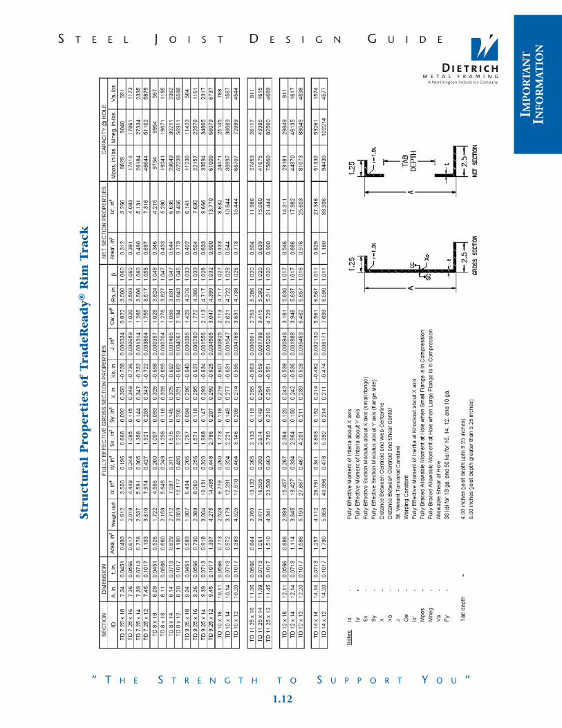
Stru
ctu
ral
Pro
per
ties
of
Tra
deR
ead
y®
Rim
Tra
ck
3.23 1.12
IMP
OR
TA
NT
INFO
RM
ATIO
N
S T E E L J O I S T D E S I G N G U I D ES T E E L J O I S T D E S I G N G U I D E
“ T H E S T R E N G T H T O S U P P O R T Y O U ”“ T H E S T R E N G T H T O S U P P O R T Y O U ”
1.13 3.22
S T E E L J O I S T D E S I G N G U I D ES T E E L J O I S T D E S I G N G U I D E
“ T H E S T R E N G T H T O S U P P O R T Y O U ”“ T H E S T R E N G T H T O S U P P O R T Y O U ”
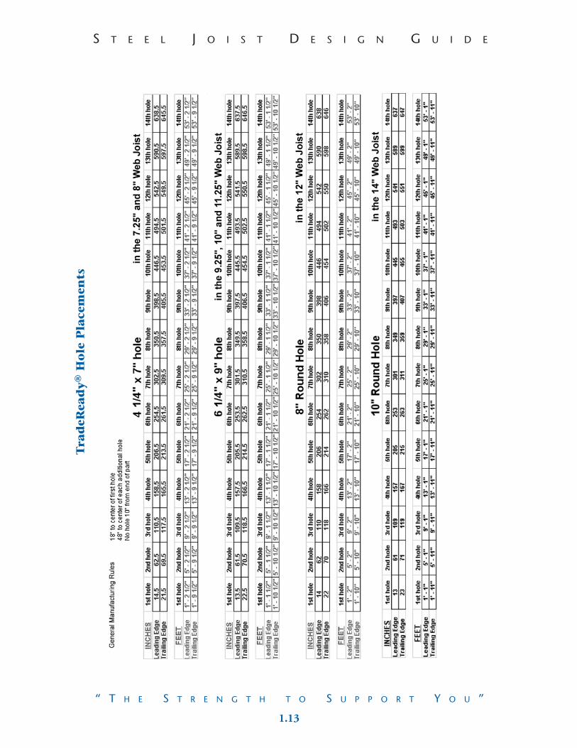
Tra
deR
ead
y®
Ho
le P
lace
men
ts
RE
FER
EN
CE
DE
TA
ILS
3.21 2.1
SPA
NS,
CR
IPP
LIN
G&
CL
IPS
S T E E L J O I S T D E S I G N G U I D ES T E E L J O I S T D E S I G N G U I D E
“ T H E S T R E N G T H T O S U P P O R T Y O U ”“ T H E S T R E N G T H T O S U P P O R T Y O U ”
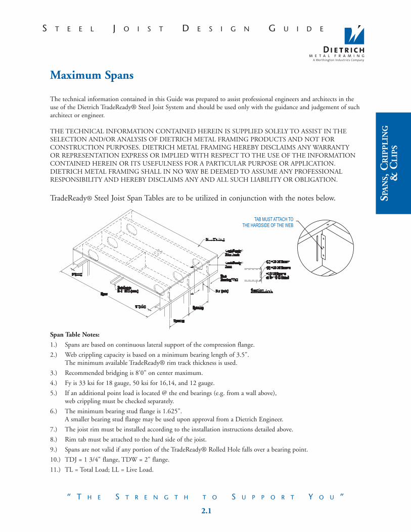
Maximum Spans
The technical information contained in this Guide was prepared to assist professional engineers and architects in theuse of the Dietrich TradeReady® Steel Joist System and should be used only with the guidance and judgement of sucharchitect or engineer.
THE TECHNICAL INFORMATION CONTAINED HEREIN IS SUPPLIED SOLELY TO ASSIST IN THESELECTION AND/OR ANALYSIS OF DIETRICH METAL FRAMING PRODUCTS AND NOT FORCONSTRUCTION PURPOSES. DIETRICH METAL FRAMING HEREBY DISCLAIMS ANY WARRANTYOR REPRESENTATION EXPRESS OR IMPLIED WITH RESPECT TO THE USE OF THE INFORMATIONCONTAINED HEREIN OR ITS USEFULNESS FOR A PARTICULAR PURPOSE OR APPLICATION.DIETRICH METAL FRAMING SHALL IN NO WAY BE DEEMED TO ASSUME ANY PROFESSIONALRESPONSIBILITY AND HEREBY DISCLAIMS ANY AND ALL SUCH LIABILITY OR OBLIGATION.
TradeReady® Steel Joist Span Tables are to be utilized in conjunction with the notes below.
Span Table Notes:
1.) Spans are based on continuous lateral support of the compression flange.
2.) Web crippling capacity is based on a minimum bearing length of 3.5". The minimum available TradeReady® rim track thickness is used.
3.) Recommended bridging is 8'0" on center maximum.
4.) Fy is 33 ksi for 18 gauge, 50 ksi for 16,14, and 12 gauge.
5.) If an additional point load is located @ the end bearings (e.g. from a wall above), web crippling must be checked separately.
6.) The minimum bearing stud flange is 1.625". A smaller bearing stud flange may be used upon approval from a Dietrich Engineer.
7.) The joist rim must be installed according to the installation instructions detailed above.
8.) Rim tab must be attached to the hard side of the joist.
9.) Spans are not valid if any portion of the TradeReady® Rolled Hole falls over a bearing point.
10.) TDJ = 1 3/4" flange, TDW = 2" flange.
11.) TL = Total Load; LL = Live Load.

2.2 3.20
S T E E L J O I S T D E S I G N G U I D ES T E E L J O I S T D E S I G N G U I D E
“ T H E S T R E N G T H T O S U P P O R T Y O U ”“ T H E S T R E N G T H T O S U P P O R T Y O U ”
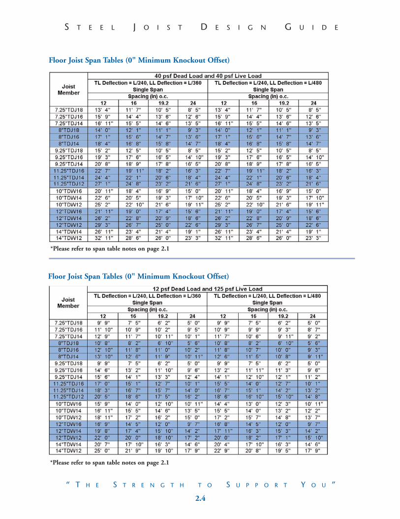
Floor Joist Span Tables (0" Minimum Knockout Offset)
Floor Joist Span Tables (0" Minimum Knockout Offset)
RE
FER
EN
CE
DE
TA
ILS
*Please refer to span table notes on page 2.1
*Please refer to span table notes on page 2.1

3.19 2.3
SPA
NS,
CR
IPP
LIN
G&
CL
IPS
S T E E L J O I S T D E S I G N G U I D ES T E E L J O I S T D E S I G N G U I D E
“ T H E S T R E N G T H T O S U P P O R T Y O U ”“ T H E S T R E N G T H T O S U P P O R T Y O U ”
Floor Joist Span Tables (0" Minimum Knockout Offset)
Floor Joist Span Tables (0" Minimum Knockout Offset)
*Please refer to span table notes on page 2.1
*Please refer to span table notes on page 2.1
2.4 3.18
S T E E L J O I S T D E S I G N G U I D ES T E E L J O I S T D E S I G N G U I D E
“ T H E S T R E N G T H T O S U P P O R T Y O U ”“ T H E S T R E N G T H T O S U P P O R T Y O U ”
Floor Joist Span Tables (0" Minimum Knockout Offset)
Floor Joist Span Tables (0" Minimum Knockout Offset)
RE
FER
EN
CE
DE
TA
ILS
*Please refer to span table notes on page 2.1
*Please refer to span table notes on page 2.1

3.17 2.5
SPA
NS,
CR
IPP
LIN
G&
CL
IPS
S T E E L J O I S T D E S I G N G U I D ES T E E L J O I S T D E S I G N G U I D E
“ T H E S T R E N G T H T O S U P P O R T Y O U ”“ T H E S T R E N G T H T O S U P P O R T Y O U ”
Web Crippling

2.6 3.16
S T E E L J O I S T D E S I G N G U I D ES T E E L J O I S T D E S I G N G U I D E
“ T H E S T R E N G T H T O S U P P O R T Y O U ”“ T H E S T R E N G T H T O S U P P O R T Y O U ”
Web Crippling
RE
FER
EN
CE
DE
TA
ILS
3.15 2.7
SPA
NS,
CR
IPP
LIN
G&
CL
IPS
S T E E L J O I S T D E S I G N G U I D ES T E E L J O I S T D E S I G N G U I D E
“ T H E S T R E N G T H T O S U P P O R T Y O U ”“ T H E S T R E N G T H T O S U P P O R T Y O U ”
Web Crippling

2.8 3.14
S T E E L J O I S T D E S I G N G U I D ES T E E L J O I S T D E S I G N G U I D E
“ T H E S T R E N G T H T O S U P P O R T Y O U ”“ T H E S T R E N G T H T O S U P P O R T Y O U ”
Web Crippling
RE
FER
EN
CE
DE
TA
ILS
3.13 2.9
SPA
NS,
CR
IPP
LIN
G&
CL
IPS
S T E E L J O I S T D E S I G N G U I D ES T E E L J O I S T D E S I G N G U I D E
“ T H E S T R E N G T H T O S U P P O R T Y O U ”“ T H E S T R E N G T H T O S U P P O R T Y O U ”
Support Clips

2.10 3.12
S T E E L J O I S T D E S I G N G U I D ES T E E L J O I S T D E S I G N G U I D E
“ T H E S T R E N G T H T O S U P P O R T Y O U ”“ T H E S T R E N G T H T O S U P P O R T Y O U ”
Support Clips
RE
FER
EN
CE
DE
TA
ILS
3.11 2.11
SPA
NS,
CR
IPP
LIN
G&
CL
IPS
S T E E L J O I S T D E S I G N G U I D ES T E E L J O I S T D E S I G N G U I D E
“ T H E S T R E N G T H T O S U P P O R T Y O U ”“ T H E S T R E N G T H T O S U P P O R T Y O U ”
Support Clips

3.1 3.10
S T E E L J O I S T D E S I G N G U I D ES T E E L J O I S T D E S I G N G U I D E
“ T H E S T R E N G T H T O S U P P O R T Y O U ”“ T H E S T R E N G T H T O S U P P O R T Y O U ”
TradeReady® Framing and Construction Reference Details
The technical information contained in this Guide was prepared to assist professional engineers and architects in theuse of the Dietrich TradeReady® Steel Joist System and should be used only with the guidance and judgement of sucharchitect or engineer.
The details provided herein should be reviewed for the following conditions:
Specific attachment requirements• Attachments typically are screws, pins, nails, or other types of connectors.• All attachment references should be reviewed for size, quantity, and
manufacturer by the E.O.R. • As a guide and reference only, some connection locations and size and quantity may
be indicated by either a written note or by symbol (+) or both.• Following the details section are specific connector values to assist in sizing the
connections for some of the attachment details. For girder and beam attachments, please refer to the Support Clips tables.
Tables and Notes• The tables reference specific construction conditions. The information in these
tables should be addressed by the E.O.R.
The sizing of clips and connectors may be effected.
• Notes are shown to address conditions that may be beyond the scope of the referenced detail. These conditions should be reviewed by the E.O.R.
Per PlanMany details are applicable to different building plans. Because specific member selection often changes from one application to another, several details include the note "per plan." The "per plan" citation may effect the framing members and the connectors used (see Specific Attachment Requirements above).
By OthersThe following details show general framing and construction conditions applicable to the Dietrich TradeReady® Steel Joist System only.All other building components and their interaction with the TradeReady® Steel JoistSystem should be reviewed and specified by the E.O.R.
NOTES: Reference all notes at the back of this design guide: General, Installation,and Material.
RE
FER
EN
CE
DE
TA
ILS
3.9 3.2
RE
FER
EN
CE
DE
TA
ILS
S T E E L J O I S T D E S I G N G U I D ES T E E L J O I S T D E S I G N G U I D E
“ T H E S T R E N G T H T O S U P P O R T Y O U ”“ T H E S T R E N G T H T O S U P P O R T Y O U ”
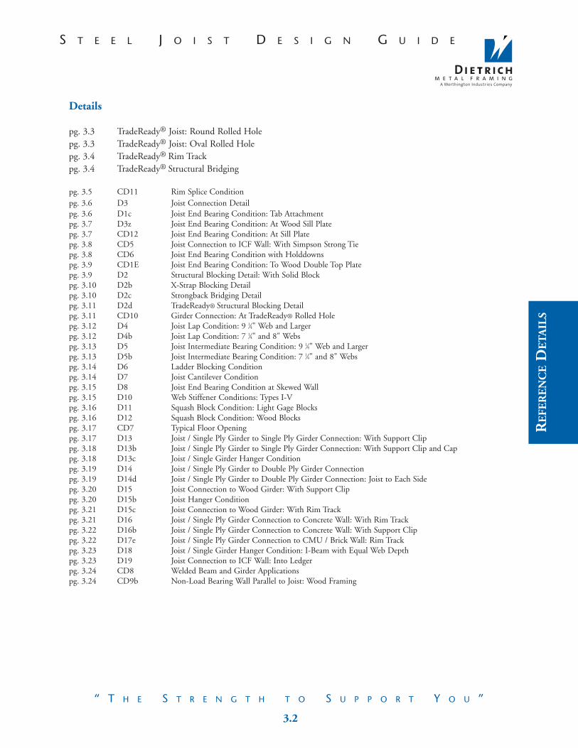
Details
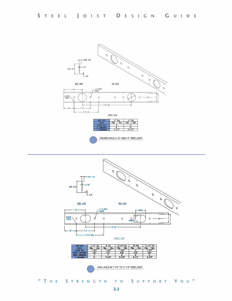
pg. 3.3 TradeReady® Joist: Round Rolled Holepg. 3.3 TradeReady® Joist: Oval Rolled Holepg. 3.4 TradeReady® Rim Trackpg. 3.4 TradeReady® Structural Bridging
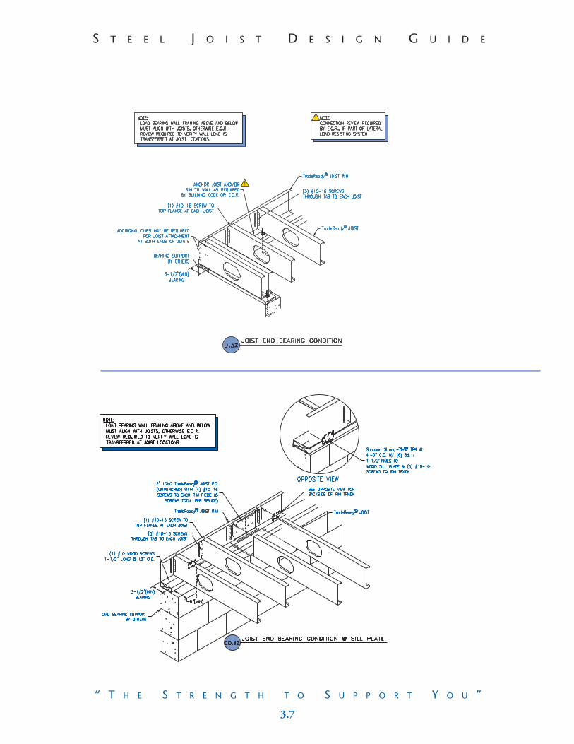
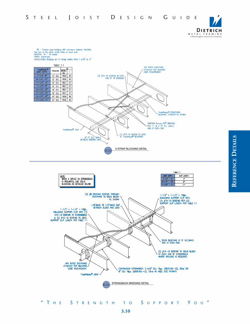
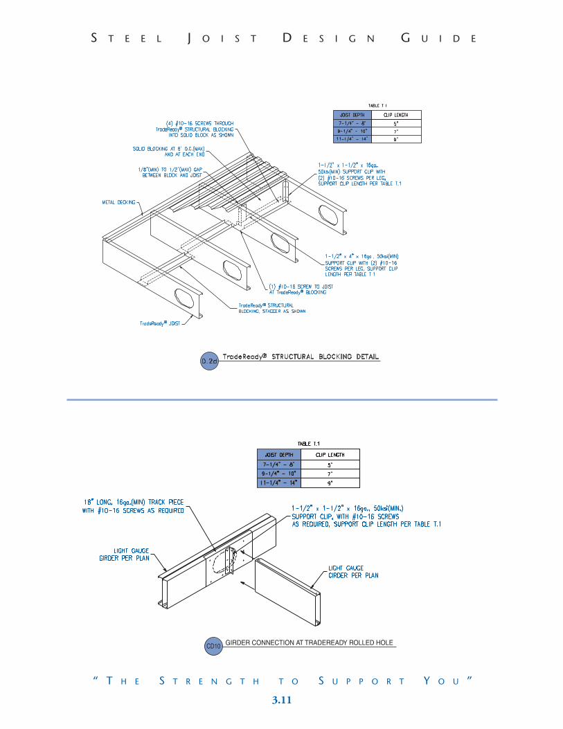
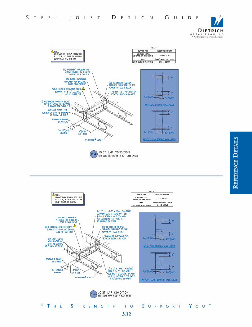
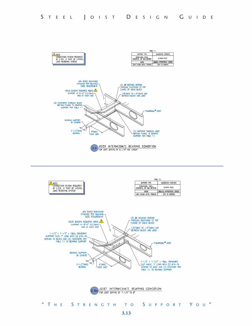
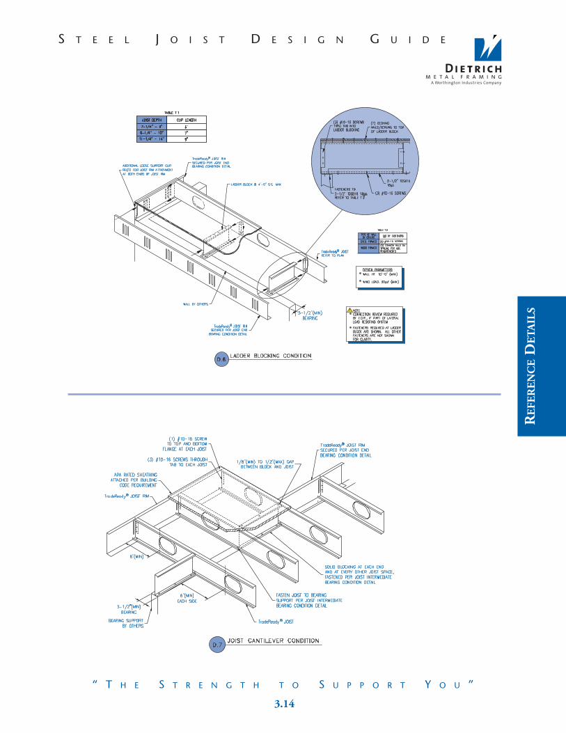
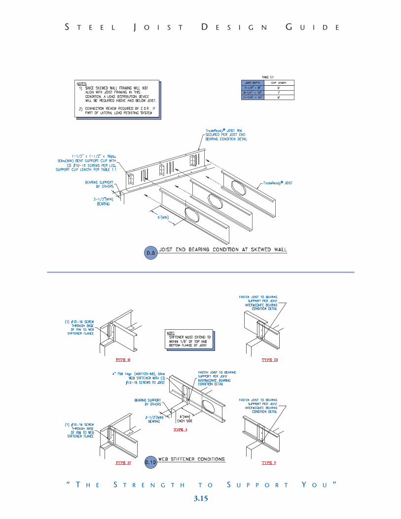
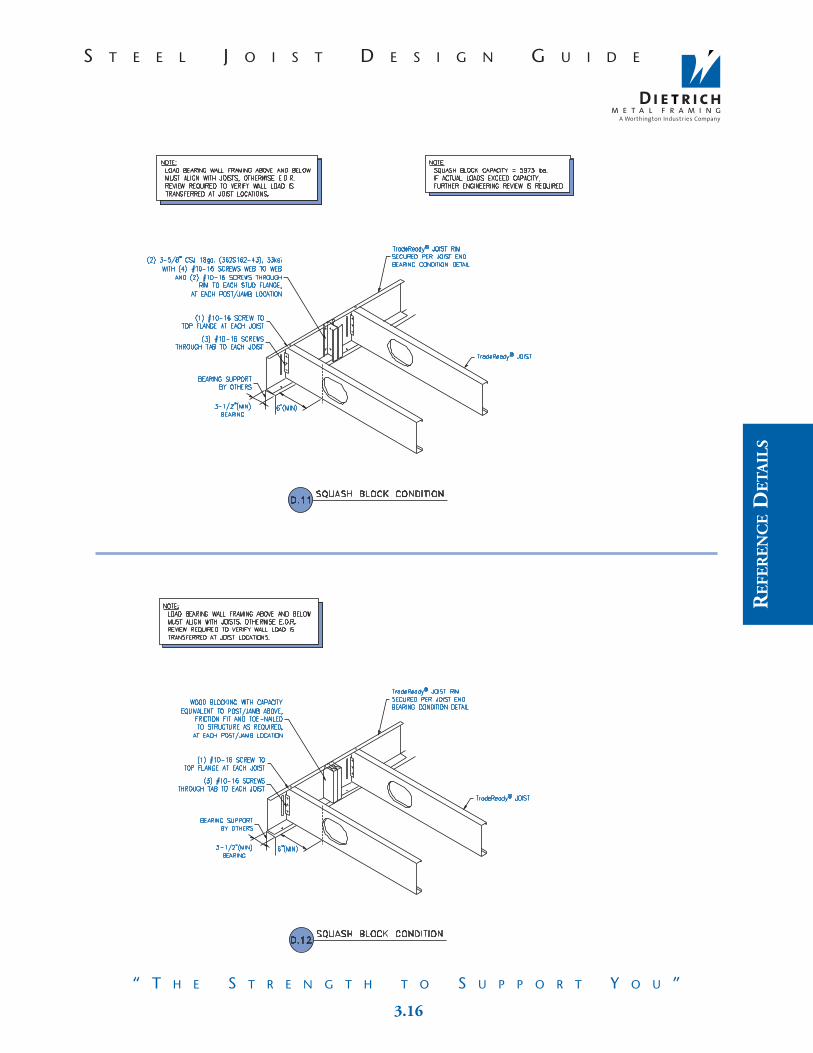
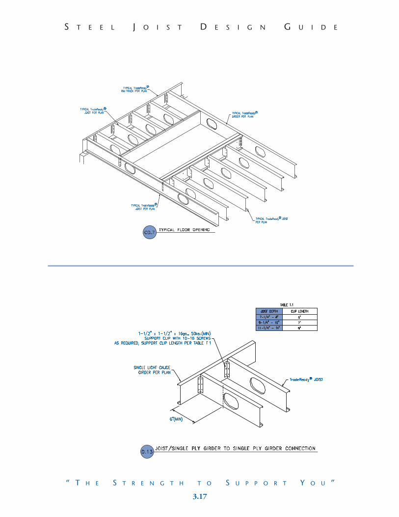
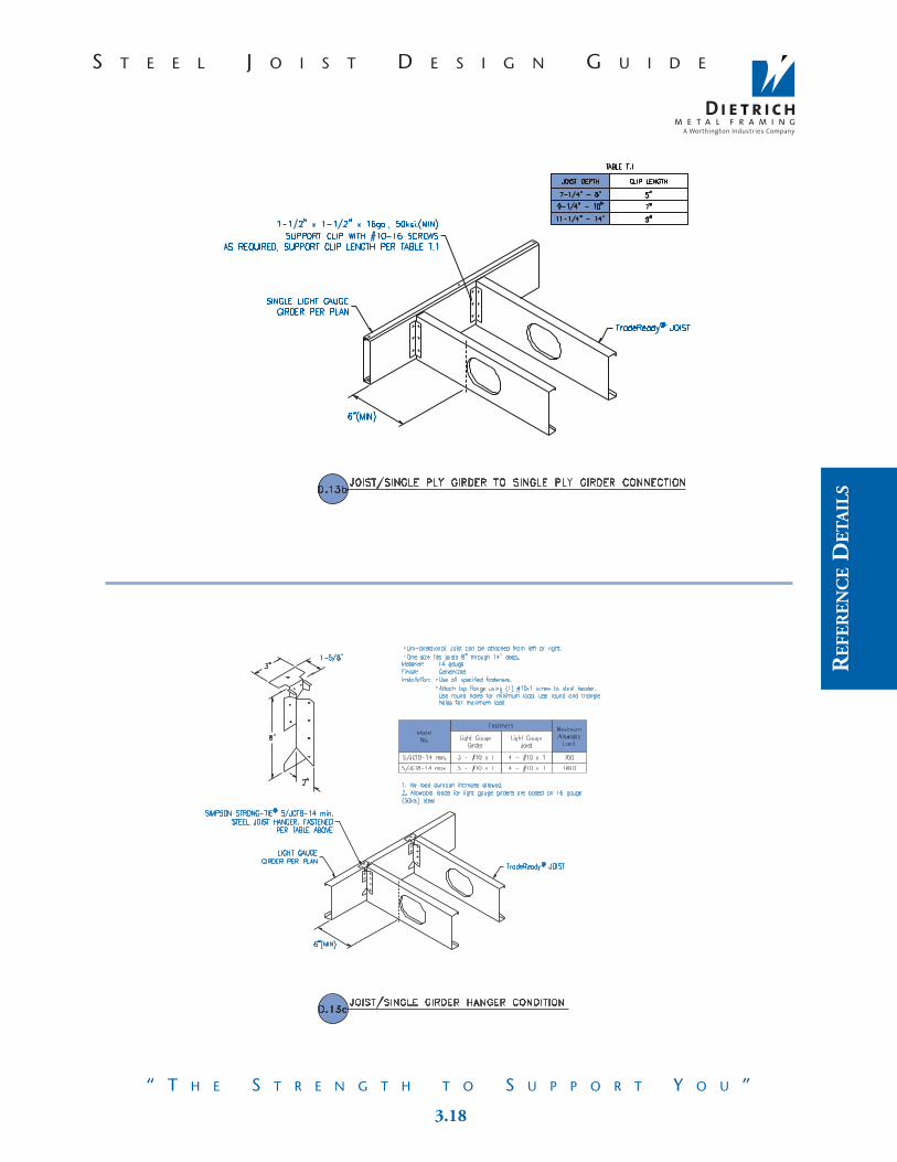
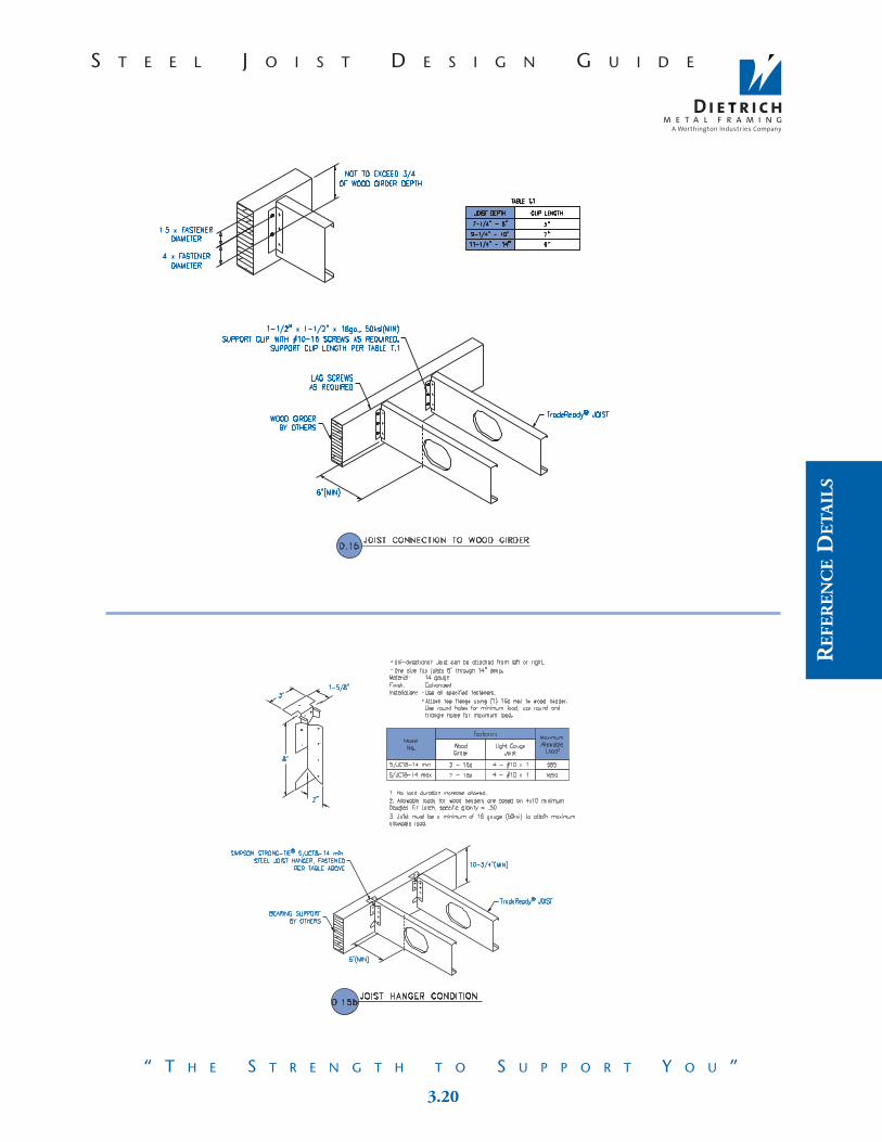
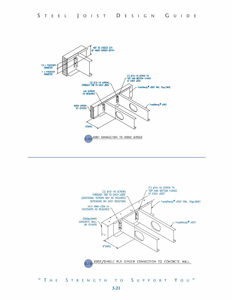
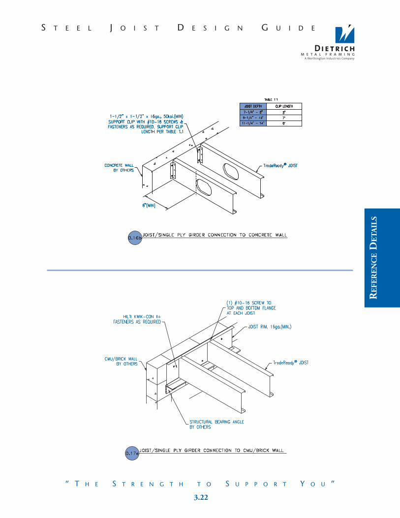
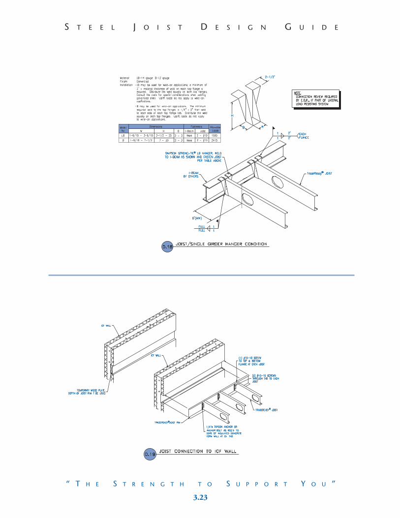
pg. 3.5 CD11 Rim Splice Conditionpg. 3.6 D3 Joist Connection Detailpg. 3.6 D1c Joist End Bearing Condition: Tab Attachmentpg. 3.7 D3z Joist End Bearing Condition: At Wood Sill Platepg. 3.7 CD12 Joist End Bearing Condition: At Sill Platepg. 3.8 CD5 Joist Connection to ICF Wall: With Simpson Strong Tiepg. 3.8 CD6 Joist End Bearing Condition with Holddownspg. 3.9 CD1E Joist End Bearing Condition: To Wood Double Top Platepg. 3.9 D2 Structural Blocking Detail: With Solid Blockpg. 3.10 D2b X-Strap Blocking Detailpg. 3.10 D2c Strongback Bridging Detailpg. 3.11 D2d TradeReady® Structural Blocking Detail pg. 3.11 CD10 Girder Connection: At TradeReady® Rolled Holepg. 3.12 D4 Joist Lap Condition: 9 1⁄4" Web and Largerpg. 3.12 D4b Joist Lap Condition: 7 1⁄4" and 8" Webspg. 3.13 D5 Joist Intermediate Bearing Condition: 9 1⁄4" Web and Largerpg. 3.13 D5b Joist Intermediate Bearing Condition: 7 1⁄4" and 8" Webspg. 3.14 D6 Ladder Blocking Conditionpg. 3.14 D7 Joist Cantilever Conditionpg. 3.15 D8 Joist End Bearing Condition at Skewed Wallpg. 3.15 D10 Web Stiffener Conditions: Types I-Vpg. 3.16 D11 Squash Block Condition: Light Gage Blockspg. 3.16 D12 Squash Block Condition: Wood Blockspg. 3.17 CD7 Typical Floor Openingpg. 3.17 D13 Joist / Single Ply Girder to Single Ply Girder Connection: With Support Clippg. 3.18 D13b Joist / Single Ply Girder to Single Ply Girder Connection: With Support Clip and Cappg. 3.18 D13c Joist / Single Girder Hanger Conditionpg. 3.19 D14 Joist / Single Ply Girder to Double Ply Girder Connection pg. 3.19 D14d Joist / Single Ply Girder to Double Ply Girder Connection: Joist to Each Sidepg. 3.20 D15 Joist Connection to Wood Girder: With Support Clippg. 3.20 D15b Joist Hanger Conditionpg. 3.21 D15c Joist Connection to Wood Girder: With Rim Trackpg. 3.21 D16 Joist / Single Ply Girder Connection to Concrete Wall: With Rim Trackpg. 3.22 D16b Joist / Single Ply Girder Connection to Concrete Wall: With Support Clippg. 3.22 D17e Joist / Single Ply Girder Connection to CMU / Brick Wall: Rim Trackpg. 3.23 D18 Joist / Single Girder Hanger Condition: I-Beam with Equal Web Depthpg. 3.23 D19 Joist Connection to ICF Wall: Into Ledgerpg. 3.24 CD8 Welded Beam and Girder Applicationspg. 3.24 CD9b Non-Load Bearing Wall Parallel to Joist: Wood Framing
3.3 3.8
S T E E L J O I S T D E S I G N G U I D ES T E E L J O I S T D E S I G N G U I D E
“ T H E S T R E N G T H T O S U P P O R T Y O U ”“ T H E S T R E N G T H T O S U P P O R T Y O U ”
RE
FER
EN
CE
DE
TA
ILS

3.7 3.4
RE
FER
EN
CE
DE
TA
ILS
S T E E L J O I S T D E S I G N G U I D ES T E E L J O I S T D E S I G N G U I D E
“ T H E S T R E N G T H T O S U P P O R T Y O U ”“ T H E S T R E N G T H T O S U P P O R T Y O U ”

3.5 3.6
S T E E L J O I S T D E S I G N G U I D ES T E E L J O I S T D E S I G N G U I D E
“ T H E S T R E N G T H T O S U P P O R T Y O U ”“ T H E S T R E N G T H T O S U P P O R T Y O U ”
This Space is Intentionally Left Blank
RE
FER
EN
CE
DE
TA
ILS

3.5 3.6
S T E E L J O I S T D E S I G N G U I D ES T E E L J O I S T D E S I G N G U I D E
“ T H E S T R E N G T H T O S U P P O R T Y O U ”“ T H E S T R E N G T H T O S U P P O R T Y O U ”
This Space is Intentionally Left Blank
RE
FER
EN
CE
DE
TA
ILS
3.7 3.4
RE
FER
EN
CE
DE
TA
ILS
S T E E L J O I S T D E S I G N G U I D ES T E E L J O I S T D E S I G N G U I D E
“ T H E S T R E N G T H T O S U P P O R T Y O U ”“ T H E S T R E N G T H T O S U P P O R T Y O U ”

3.3 3.8
S T E E L J O I S T D E S I G N G U I D ES T E E L J O I S T D E S I G N G U I D E
“ T H E S T R E N G T H T O S U P P O R T Y O U ”“ T H E S T R E N G T H T O S U P P O R T Y O U ”
RE
FER
EN
CE
DE
TA
ILS

3.9 3.2
RE
FER
EN
CE
DE
TA
ILS
S T E E L J O I S T D E S I G N G U I D ES T E E L J O I S T D E S I G N G U I D E
“ T H E S T R E N G T H T O S U P P O R T Y O U ”“ T H E S T R E N G T H T O S U P P O R T Y O U ”
Details
pg. 3.3 TradeReady® Joist: Round Rolled Holepg. 3.3 TradeReady® Joist: Oval Rolled Holepg. 3.4 TradeReady® Rim Trackpg. 3.4 TradeReady® Structural Bridging
pg. 3.5 CD11 Rim Splice Conditionpg. 3.6 D3 Joist Connection Detailpg. 3.6 D1c Joist End Bearing Condition: Tab Attachmentpg. 3.7 D3z Joist End Bearing Condition: At Wood Sill Platepg. 3.7 CD12 Joist End Bearing Condition: At Sill Platepg. 3.8 CD5 Joist Connection to ICF Wall: With Simpson Strong Tiepg. 3.8 CD6 Joist End Bearing Condition with Holddownspg. 3.9 CD1E Joist End Bearing Condition: To Wood Double Top Platepg. 3.9 D2 Structural Blocking Detail: With Solid Blockpg. 3.10 D2b X-Strap Blocking Detailpg. 3.10 D2c Strongback Bridging Detailpg. 3.11 D2d TradeReady® Structural Blocking Detail pg. 3.11 CD10 Girder Connection: At TradeReady® Rolled Holepg. 3.12 D4 Joist Lap Condition: 9 1⁄4" Web and Largerpg. 3.12 D4b Joist Lap Condition: 7 1⁄4" and 8" Webspg. 3.13 D5 Joist Intermediate Bearing Condition: 9 1⁄4" Web and Largerpg. 3.13 D5b Joist Intermediate Bearing Condition: 7 1⁄4" and 8" Webspg. 3.14 D6 Ladder Blocking Conditionpg. 3.14 D7 Joist Cantilever Conditionpg. 3.15 D8 Joist End Bearing Condition at Skewed Wallpg. 3.15 D10 Web Stiffener Conditions: Types I-Vpg. 3.16 D11 Squash Block Condition: Light Gage Blockspg. 3.16 D12 Squash Block Condition: Wood Blockspg. 3.17 CD7 Typical Floor Openingpg. 3.17 D13 Joist / Single Ply Girder to Single Ply Girder Connection: With Support Clippg. 3.18 D13b Joist / Single Ply Girder to Single Ply Girder Connection: With Support Clip and Cappg. 3.18 D13c Joist / Single Girder Hanger Conditionpg. 3.19 D14 Joist / Single Ply Girder to Double Ply Girder Connection pg. 3.19 D14d Joist / Single Ply Girder to Double Ply Girder Connection: Joist to Each Sidepg. 3.20 D15 Joist Connection to Wood Girder: With Support Clippg. 3.20 D15b Joist Hanger Conditionpg. 3.21 D15c Joist Connection to Wood Girder: With Rim Trackpg. 3.21 D16 Joist / Single Ply Girder Connection to Concrete Wall: With Rim Trackpg. 3.22 D16b Joist / Single Ply Girder Connection to Concrete Wall: With Support Clippg. 3.22 D17e Joist / Single Ply Girder Connection to CMU / Brick Wall: Rim Trackpg. 3.23 D18 Joist / Single Girder Hanger Condition: I-Beam with Equal Web Depthpg. 3.23 D19 Joist Connection to ICF Wall: Into Ledgerpg. 3.24 CD8 Welded Beam and Girder Applicationspg. 3.24 CD9b Non-Load Bearing Wall Parallel to Joist: Wood Framing
3.1 3.10
S T E E L J O I S T D E S I G N G U I D ES T E E L J O I S T D E S I G N G U I D E
“ T H E S T R E N G T H T O S U P P O R T Y O U ”“ T H E S T R E N G T H T O S U P P O R T Y O U ”
TradeReady® Framing and Construction Reference Details
The technical information contained in this Guide was prepared to assist professional engineers and architects in theuse of the Dietrich TradeReady® Steel Joist System and should be used only with the guidance and judgement of sucharchitect or engineer.
The details provided herein should be reviewed for the following conditions:
Specific attachment requirements• Attachments typically are screws, pins, nails, or other types of connectors.• All attachment references should be reviewed for size, quantity, and
manufacturer by the E.O.R. • As a guide and reference only, some connection locations and size and quantity may
be indicated by either a written note or by symbol (+) or both.• Following the details section are specific connector values to assist in sizing the
connections for some of the attachment details. For girder and beam attachments, please refer to the Support Clips tables.
Tables and Notes• The tables reference specific construction conditions. The information in these
tables should be addressed by the E.O.R.
The sizing of clips and connectors may be effected.
• Notes are shown to address conditions that may be beyond the scope of the referenced detail. These conditions should be reviewed by the E.O.R.
Per PlanMany details are applicable to different building plans. Because specific member selection often changes from one application to another, several details include the note "per plan." The "per plan" citation may effect the framing members and the connectors used (see Specific Attachment Requirements above).
By OthersThe following details show general framing and construction conditions applicable to the Dietrich TradeReady® Steel Joist System only.All other building components and their interaction with the TradeReady® Steel JoistSystem should be reviewed and specified by the E.O.R.
NOTES: Reference all notes at the back of this design guide: General, Installation,and Material.
RE
FER
EN
CE
DE
TA
ILS
3.11 2.11
SPA
NS,
CR
IPP
LIN
G&
CL
IPS
S T E E L J O I S T D E S I G N G U I D ES T E E L J O I S T D E S I G N G U I D E
“ T H E S T R E N G T H T O S U P P O R T Y O U ”“ T H E S T R E N G T H T O S U P P O R T Y O U ”
Support Clips
2.10 3.12
S T E E L J O I S T D E S I G N G U I D ES T E E L J O I S T D E S I G N G U I D E
“ T H E S T R E N G T H T O S U P P O R T Y O U ”“ T H E S T R E N G T H T O S U P P O R T Y O U ”
Support Clips
RE
FER
EN
CE
DE
TA
ILS
3.13 2.9
SPA
NS,
CR
IPP
LIN
G&
CL
IPS
S T E E L J O I S T D E S I G N G U I D ES T E E L J O I S T D E S I G N G U I D E
“ T H E S T R E N G T H T O S U P P O R T Y O U ”“ T H E S T R E N G T H T O S U P P O R T Y O U ”
Support Clips
2.8 3.14
S T E E L J O I S T D E S I G N G U I D ES T E E L J O I S T D E S I G N G U I D E
“ T H E S T R E N G T H T O S U P P O R T Y O U ”“ T H E S T R E N G T H T O S U P P O R T Y O U ”
Web Crippling
RE
FER
EN
CE
DE
TA
ILS
3.15 2.7
SPA
NS,
CR
IPP
LIN
G&
CL
IPS
S T E E L J O I S T D E S I G N G U I D ES T E E L J O I S T D E S I G N G U I D E
“ T H E S T R E N G T H T O S U P P O R T Y O U ”“ T H E S T R E N G T H T O S U P P O R T Y O U ”
Web Crippling
2.6 3.16
S T E E L J O I S T D E S I G N G U I D ES T E E L J O I S T D E S I G N G U I D E
“ T H E S T R E N G T H T O S U P P O R T Y O U ”“ T H E S T R E N G T H T O S U P P O R T Y O U ”
Web Crippling
RE
FER
EN
CE
DE
TA
ILS
3.17 2.5
SPA
NS,
CR
IPP
LIN
G&
CL
IPS
S T E E L J O I S T D E S I G N G U I D ES T E E L J O I S T D E S I G N G U I D E
“ T H E S T R E N G T H T O S U P P O R T Y O U ”“ T H E S T R E N G T H T O S U P P O R T Y O U ”
Web Crippling
2.4 3.18
S T E E L J O I S T D E S I G N G U I D ES T E E L J O I S T D E S I G N G U I D E
“ T H E S T R E N G T H T O S U P P O R T Y O U ”“ T H E S T R E N G T H T O S U P P O R T Y O U ”
Floor Joist Span Tables (0" Minimum Knockout Offset)
Floor Joist Span Tables (0" Minimum Knockout Offset)
RE
FER
EN
CE
DE
TA
ILS
*Please refer to span table notes on page 2.1
*Please refer to span table notes on page 2.1

3.19 2.3
SPA
NS,
CR
IPP
LIN
G&
CL
IPS
S T E E L J O I S T D E S I G N G U I D ES T E E L J O I S T D E S I G N G U I D E
“ T H E S T R E N G T H T O S U P P O R T Y O U ”“ T H E S T R E N G T H T O S U P P O R T Y O U ”
Floor Joist Span Tables (0" Minimum Knockout Offset)
Floor Joist Span Tables (0" Minimum Knockout Offset)
*Please refer to span table notes on page 2.1
*Please refer to span table notes on page 2.1
2.2 3.20
S T E E L J O I S T D E S I G N G U I D ES T E E L J O I S T D E S I G N G U I D E
“ T H E S T R E N G T H T O S U P P O R T Y O U ”“ T H E S T R E N G T H T O S U P P O R T Y O U ”
Floor Joist Span Tables (0" Minimum Knockout Offset)
Floor Joist Span Tables (0" Minimum Knockout Offset)
RE
FER
EN
CE
DE
TA
ILS
*Please refer to span table notes on page 2.1
*Please refer to span table notes on page 2.1
3.21 2.1
SPA
NS,
CR
IPP
LIN
G&
CL
IPS
S T E E L J O I S T D E S I G N G U I D ES T E E L J O I S T D E S I G N G U I D E
“ T H E S T R E N G T H T O S U P P O R T Y O U ”“ T H E S T R E N G T H T O S U P P O R T Y O U ”
Maximum Spans
The technical information contained in this Guide was prepared to assist professional engineers and architects in theuse of the Dietrich TradeReady® Steel Joist System and should be used only with the guidance and judgement of sucharchitect or engineer.
THE TECHNICAL INFORMATION CONTAINED HEREIN IS SUPPLIED SOLELY TO ASSIST IN THESELECTION AND/OR ANALYSIS OF DIETRICH METAL FRAMING PRODUCTS AND NOT FORCONSTRUCTION PURPOSES. DIETRICH METAL FRAMING HEREBY DISCLAIMS ANY WARRANTYOR REPRESENTATION EXPRESS OR IMPLIED WITH RESPECT TO THE USE OF THE INFORMATIONCONTAINED HEREIN OR ITS USEFULNESS FOR A PARTICULAR PURPOSE OR APPLICATION.DIETRICH METAL FRAMING SHALL IN NO WAY BE DEEMED TO ASSUME ANY PROFESSIONALRESPONSIBILITY AND HEREBY DISCLAIMS ANY AND ALL SUCH LIABILITY OR OBLIGATION.
TradeReady® Steel Joist Span Tables are to be utilized in conjunction with the notes below.
Span Table Notes:
1.) Spans are based on continuous lateral support of the compression flange.
2.) Web crippling capacity is based on a minimum bearing length of 3.5". The minimum available TradeReady® rim track thickness is used.
3.) Recommended bridging is 8'0" on center maximum.
4.) Fy is 33 ksi for 18 gauge, 50 ksi for 16,14, and 12 gauge.
5.) If an additional point load is located @ the end bearings (e.g. from a wall above), web crippling must be checked separately.
6.) The minimum bearing stud flange is 1.625". A smaller bearing stud flange may be used upon approval from a Dietrich Engineer.
7.) The joist rim must be installed according to the installation instructions detailed above.
8.) Rim tab must be attached to the hard side of the joist.
9.) Spans are not valid if any portion of the TradeReady® Rolled Hole falls over a bearing point.
10.) TDJ = 1 3/4" flange, TDW = 2" flange.
11.) TL = Total Load; LL = Live Load.
1.13 3.22
S T E E L J O I S T D E S I G N G U I D ES T E E L J O I S T D E S I G N G U I D E
“ T H E S T R E N G T H T O S U P P O R T Y O U ”“ T H E S T R E N G T H T O S U P P O R T Y O U ”
Tra
deR
ead
y®
Ho
le P
lace
men
ts
RE
FER
EN
CE
DE
TA
ILS
Stru
ctu
ral
Pro
per
ties
of
Tra
deR
ead
y®
Rim
Tra
ck
3.23 1.12
IMP
OR
TA
NT
INFO
RM
ATIO
N
S T E E L J O I S T D E S I G N G U I D ES T E E L J O I S T D E S I G N G U I D E
“ T H E S T R E N G T H T O S U P P O R T Y O U ”“ T H E S T R E N G T H T O S U P P O R T Y O U ”

1.11 3.24
S T E E L J O I S T D E S I G N G U I D ES T E E L J O I S T D E S I G N G U I D E
“ T H E S T R E N G T H T O S U P P O R T Y O U ”“ T H E S T R E N G T H T O S U P P O R T Y O U ”
Stru
ctu
ral
Pro
per
ties
of
Tra
deR
ead
y®
Jois
t: 7
1 ⁄4"
to 1
4"
Web
RE
FER
EN
CE
DE
TA
ILS

3.25 1.10
IMP
OR
TA
NT
INFO
RM
ATIO
N
S T E E L J O I S T D E S I G N G U I D ES T E E L J O I S T D E S I G N G U I D E
“ T H E S T R E N G T H T O S U P P O R T Y O U ”“ T H E S T R E N G T H T O S U P P O R T Y O U ”
Dietrich Skid Label
1 2 3 4 51. Quality Control Identification/Tracking System2. Product Gage3. Web Depth of Material in Inches4. Length of Material5. Dietrich Product Code
OTHER DETAILS: AVAILABLE UPON REQUEST*
D1 Joist End BearingD1b Double Joist End BearingD2f Structural Blocking with Double JoistD3zz Joist Framing at Basement WindowD4c Joist Lap Condition: On Light Gage Metal Framing BearingD4d Double Joist with Single Joist LapD5c Joist Intermediate Bearing Condition: On Light Gage Metal Framing BearingD5f Double Joist Intermediate Bearing Condition: On Light Gage Metal Framing BearingD6b Ladder Blocking Condition: From Built Up End JoistD6c Ladder Blocking Condition: Into Double JoistD6d Ladder Blocking Condition: From Built Up End Joist Into Double JoistD6e Ladder Blocking Condition: At Equal O.C. Spacing of JoistD6f Ladder Blocking Condition: Rim to RimD7b Double Joist Cantilever ConditionD8b Joist End Bearing Condition: Continuous SpanD9 Joist Rim to Rim Condition: Upside Down RimD9b End Joist Condition: Rim to RimD9c Joist / Single Ply Girder Rim to Rim Connection: Upside Down Rim – Non Equal WebsD11b Rim Stiffener Condition: Light Gage Metal FramingD12b Rim Stiffener Condition: Wood BlocksD13d Joist Connection to Light Gage GirderD14b Joist / Single Ply Girder to Double Ply Girder Connection: CappedD14c Joist / Single Ply Girder to Double Ply Girder Connection: Two CapsD16c End Joist Wall Condition: Parallel to Concrete WallD17 Joist / Single Ply Girder Connection to CMU / Brick Wall: Rim TrackD17b Joist / Single Ply Girder Connection to CMU / Brick Wall: Clip AngleD17c End Joist Wall ConditionD17d Joist Single Ply Girder Connection to CMU / Brick Wall: 14" JoistD18b Joist / Single Girder Hanger Condition: I-Beam, Web Greater Than JoistD19b End Joist Condition @ ICF Wall: Joist into ICFD20 Single Ply Girder to Single Ply Girder ConnectionD20b Single Ply Girder to Single Ply Girder Connection: Girder Capped with TrackD21 Single Ply Girder to Double Ply Girder ConnectionD21b Single Ply Girder to Double Ply Girder Connection: Girder Capped with TrackD21c Single Ply Girder to Double Ply Girder Connection: Both Girders Capped with TrackD22 Double Ply Girder to Double Ply Girder ConnectionD23 Single Ply Girder Connection to Concrete WallD24 Double Ply Girder Connection to Concrete WallD25 Single Ply Girder Connection to CMU / Brick WallD26 Double Ply Girder Connection to CMU / Brick WallD28 Joist Hanger Condition: Double Ply Girder to I-BeamD28b Joist Hanger Condition: Double Ply Girder to I-Beam with Simpson Clip S/JCT8-14CD2b Joist End Bearing Condition: Rim Attached with PAFCD1d Joist End Bearing Condition: As Required by EORCD2c Joist End Bearing: Attached with Rawl SpikesCD3 Joist End Bearing: to Light Gage Metal FramingCD3b Joist End Bearing: to Single Wood Top PlateCD4 Joist / Single Ply Girder Connection to Concrete Ledger WallCD9 Non-Load Bearing Wall Parallel to Joist: Light Gage Metal FramingCD10 Non-Load Bearing Wall Perpendicular to Joist: Light Gage Metal FramingCD10b Non-Load Bearing Wall Perpendicular to Joist: Wood
*Visit www.steelfloorjoist.com or call Dietrich Design Group at 219-853-9473
1.9 4.1
S T E E L J O I S T D E S I G N G U I D ES T E E L J O I S T D E S I G N G U I D E
“ T H E S T R E N G T H T O S U P P O R T Y O U ”“ T H E S T R E N G T H T O S U P P O R T Y O U ”
Product Identification
INT
HE
FIE
LD
Fastener Values
Allowable Pullout Values for Screws

4.2 1.8
IMP
OR
TA
NT
INFO
RM
ATIO
N
S T E E L J O I S T D E S I G N G U I D ES T E E L J O I S T D E S I G N G U I D E
“ T H E S T R E N G T H T O S U P P O R T Y O U ”“ T H E S T R E N G T H T O S U P P O R T Y O U ”
Tested Assemblies
FIRE TESTING
2 Hour Fire TestGA FILE NO. FC 2116
1 Hour Fire TestGA FILE NO. FC 4502GA FILE NO. FC 4503
SOUND TESTING (STC, IIC)Canadian Steel Construction Council
Assembly No: NRC764-FF22 NRC764-FF23NRC764-FF24 NRC764-FF25NRC764-FF27
Contact Information:
Gypsum Association • 810 First St., N.E. #510 • Washington D.C. 2002
Phone: 202-289-5440 • www.gypsum.org
Canadian Institute of Steel Construction • 201 Consumer Rd., Suite 300 • Willowdale, Ontario, Canada M2J4G8
Phone: 416-491-4552 • www.cisc-icca.ca
Fastener Values
Allowable Pullover Values for Various Fasteners
1.7 4.3
S T E E L J O I S T D E S I G N G U I D ES T E E L J O I S T D E S I G N G U I D E
“ T H E S T R E N G T H T O S U P P O R T Y O U ”“ T H E S T R E N G T H T O S U P P O R T Y O U ”
Code ApprovalInternational Building Code
Section 2205, Cold-Formed Steel.
International Residential CodeSection R505, Steel Floor Framing.
Contact Information:
International Code Council • 5203 Leesburg Pike, Suite 600 • Falls Church, VA 22041 • Phone: 703-931-4533
www.intlcode.org
ASTMSpecification A653/A653M-01 Standard Specification for Steel Sheet, Zinc-Coated (Galvanized) or Zinc-Iron Alloy-Coated (Galvannealed) by the Hot-Dip Process.
Specification A924/A924M-99 Standard Specification for General Requirements for Steel Sheet, Metallic-Coated by the Hot-Dip Process.
Specification C955-00a* Standard Specification for Load-Bearing (Transverse and Axial) Steel Studs, Runners (Tracks), and Bracing or Bridging for Screw Application of Gypsum Panel Products and Metal Plaster Bases.
* Note: TradeReady® joist & rim do not meet the specific requirements of section 4.6 of this standard because of its knockout size limitations. Through proprietary fabrication techniques and extensive testing, the Dietrich TradeReady® Steel Joist System has been proven to exceed this specification.
Contact Information:
ASTM International • 100 Barr Harbor Drive • PO Box C700 • West Conshohocken, PA 19428-2959
www.astm.org
Dietrich TradeReady® Steel Joist System is in accordance with the above listed codes and standards.
HUD & NAHB Research CenterThe Builders’ Guide to Residential Steel Floors, prepared by the NAHB Research Center, Inc., and sponsored by the U.S. Department of Housing and Urban Development (HUD), the National Association of Home Builders (NAHB), and Dietrich Metal Framing provides builders, code officials, homeowners, and design professionals the necessary information required to use the Dietrich TradeReady® Steel Joist System in typical residential construction.
Contact Information:
U.S. Department of Housing and Urban Development • 451 7th Street, S.W. • Washington D.C. 20410
Phone: 202-708-1112 • www.hud.gov
NAHB Research Center • 400 Prince George’s Boulevard • Upper Marlboro, MD 20774
Phone: 301-249-4000 • www.nahbrc.org
I NT
HE
F IE
LD
Field Cut Holes
4.4 1.6
IMP
OR
TA
NT
INFO
RM
ATIO
N
S T E E L J O I S T D E S I G N G U I D ES T E E L J O I S T D E S I G N G U I D E
“ T H E S T R E N G T H T O S U P P O R T Y O U ”“ T H E S T R E N G T H T O S U P P O R T Y O U ”
Services
Dietrich Metal FramingLocation: Dietrich Metal Framing is the only metal framing manufacturer with national operations anddistribution. With 19 facilities in 15 states, Dietrich has a logistical edge in serving its customers.
Dietrich Design GroupEngineering: Dietrich Design Group is the largest group of engineers devoted to light gage metal framing in the United States. The engineers at DDG can provide engineering assistance for specific framing conditions and can assist in doing take offs and shop drawings to help with your cut list.
TradeReady® TechniciansField Support: Qualified Dietrich representatives who are available for field assistance, to answer installation questions and provide tools and recommendations to increase your building proficiency with the Dietrich TradeReady® Steel Joist System.
Educational MaterialVideo: An educational video produced as the first tool for teaching the features, benefits, and basic construction methods for building with the TradeReady® Steel Joist System.
CD-ROM: A brief introduction to the TradeReady® Steel Joist System. Our business Card CD-ROM features a 4 minute video with links to our websites listed below.
World Wide WebInternet: Comprehensive web sites offering construction details, submittal information, and much more. The Dietrich web sites include: www.steelfloorjoist.com
www.dietrichmetalframing.com
Field Cut Holes

1.5 4.5
S T E E L J O I S T D E S I G N G U I D ES T E E L J O I S T D E S I G N G U I D E
“ T H E S T R E N G T H T O S U P P O R T Y O U ”“ T H E S T R E N G T H T O S U P P O R T Y O U ”
TradeReady® is…
The TradeReady® products by Dietrich Metal Framing are more than componentsand pieces… TradeReady® is a philosophy!
Offering value added products is only the beginning. Next are our services. Going beyond simple design work and a knowledgeable sales staff, TradeReady® includes:
• The TradeReady® Steel Joist System: Joist, Rim Track, and Bridging.
• Complete Floor Design and Sizing.
• Field Technical Representatives assist you and answer questions before,during and after the building process.
• Comprehensive web site offering construction details, accessory products, tools and more. Visit us at: www.steelfloorjoist.com.
The TradeReady® philosophy is to provide answers to construction and design questions before you ask.Taking a proactive position to the building process, Dietrich Metal Framing’s TradeReady® philosophyoffers not only a superior floor, they offer the strength and resources to support you.
Why Build With The TradeReady® System?
• Value
• Compatibility
• Strength
• Service
• Performance
INT
HE
FIE
LD
Field Cut Holes
4.6 1.4
IMP
OR
TA
NT
INFO
RM
ATIO
N
S T E E L J O I S T D E S I G N G U I D ES T E E L J O I S T D E S I G N G U I D E
“ T H E S T R E N G T H T O S U P P O R T Y O U ”“ T H E S T R E N G T H T O S U P P O R T Y O U ”
Dietrich Metal Framing is…
ORGANIZATION
• We believe in a divisionalized organizational structure with responsibility for performance resting with the head of each operation.
• All managers are given the operating latitude and authority to accomplish their responsibilities withinour corporate goals and objectives.
• In keeping with this philosophy, we do not create excessive corporate procedures. If procedures are necessary within a particular company operation, that manager creates them.
• We believe in a small corporate staff and support group to service the needs of our shareholdersand operating units as requested.
COMMUNICATION
• We communicate through every possible channel with our customers, employees, shareholders,suppliers and financial community.
CITIZENSHIP
• Worthington Industries practices good citizenship at all levels. We conduct our business in a professional and ethical manner.
• We encourage all our people to actively participate in community affairs.
• We support worthwhile community causes.
Field Cut Holes

1.3 4.7
S T E E L J O I S T D E S I G N G U I D ES T E E L J O I S T D E S I G N G U I D E
“ T H E S T R E N G T H T O S U P P O R T Y O U ”“ T H E S T R E N G T H T O S U P P O R T Y O U ”
Dietrich Metal Framing is…Dietrich Metal Framing is an important segment of the Worthington Industries family of value-added, metals-relatedbusinesses. With 19 facilities in 15 states, Dietrich is the only metal framing manufacturer with national operations anddistribution. Dietrich is the largest metal framing manufacturer in the world.
The Worthington Industries PhilosophyThe Worthington Industries Philosophy is based on the Golden Rule - We treat our employees, customers, suppliersand shareholders as we would like to be treated. At Worthington Industries, we encourage our employees to join in theWorthington Philosophy by helping out in the communities where they live and work.
EARNINGS
• The first corporate goal for Worthington Industries is to earn money for its shareholders and increase the value of their investment.
• We believe that the best measurement of the accomplishment of our goal is consistent growth in earnings per share.
OUR GOLDEN RULE
• We treat our customers, employees, investors and suppliers, as we would like to be treated.
PEOPLE
• We are dedicated to the belief that people are our most important asset.
• We believe people respond to recognition, opportunity to grow and fair compensation.
• We believe that compensation should be directly related to job performance and therefore use incentives, profit sharing or otherwise, in every possible situation.
• From employees we expect an honest day’s work for an honest day’s pay.
• We believe in the philosophy of continued employment for all Worthington people.
• In filling job openings every effort is expended to find candidates within Worthington, its divisions or subsidiaries.
CUSTOMERS
• Without the customer and their need for our products and services we have nothing.
• We will exert every effort to see that the customer’s quality and service requirements are met.
• Once a commitment is made to a customer, every effort is made to fulfill that obligation.
SUPPLIERS
• We cannot operate profitably without those who supply the quality materials we need.
• We ask that suppliers be competitive in the marketplace with regard to quality, pricing, delivery and volume purchased.
• We are a loyal customer to suppliers who meet our quality and service requirements through all market conditions.
In The Field: Installing the Dietrich TradeReady® Steel Joist System
1. Check Material against cut list2. Check joist layout against plumbing and HVAC requirements3. Install TradeReady® Rim Track - Set first tab on layout,
subsequent rims are butted together continuing the layout.4. Build / install girders.5. Set joist across work area.
Note the joist orientation, holes should line up.
6. Install any required web stiffeners or squash blocks prior to setting joist as perplan when possible.
7. Rotate hard side of joist to tab and screw attach through pre-punched tab holes (Fig.1).8. Attach joist to intermediate bearing locations.9. Install temporary bracing as needed.10. Install blocking/bridging and solid blocking as required.11. Attach sub flooring – glue over joist, rim and blocking and screw attach
sheathing as per details
Fig 1: Rim Tab to Hard Side of Joist Only.
INT
HE
FIE
LD

4.8 1.2
IMP
OR
TA
NT
INFO
RM
ATIO
N
S T E E L J O I S T D E S I G N G U I D ES T E E L J O I S T D E S I G N G U I D E
“ T H E S T R E N G T H T O S U P P O R T Y O U ”“ T H E S T R E N G T H T O S U P P O R T Y O U ”
Dietrich TradeReady® Steel Joist Facts
Code Compliant:Cold-Formed steel floor framing is approved in the International Building Code and InternationalResidential Code for One- and Two-Family Dwellings, section R505.
Ease of Installation:Light in weight, steel joists are easy to handle. Ordered cut to length, they reduce the need for a cutman and pre-punched holes nearly eliminate the need for making penetrations.
Consistent Quality:Steel is dimensionally stable and structurally consistent.Steel does not contain knots, twists or warps.
Light Weight:Steel has the highest strength to weight ratio of any building material and can weigh as much as40% less than corresponding wood members, reducing total building and seismic loads which mayreduce foundation and anchoring requirements.
Price Stability:The price of steel is stable and does not undergo erratic price fluctuations.
Design Flexibility:Steels superior strength allows designers to meet specific load requirements economically.
Termite and Pest Resistant:Steel framing members are impervious to termites and other wood destroying insects.
Fire Resistant:Light gage steel framing members are non-combustible.
Nationwide Distribution:Dietrich Metal Framing has nineteen manufacturing facilities strategically located throughoutthe continental United States and Hawaii.
TOOLS OF THE TRADE
Electric Shears: A hand held tool used to cut steel thicknesses up to 68-mils
Abrasive or Dry Cut Metal Blades: Used in a chop saw or circular saw for field cutting.
Plasma Cutter: Tool utilizing an electric arc for cutting steel members to length and for making penetration cuts without a pilot hole.
Screw Gun: A torque adjustable, clutch activated
screw gun operating from 0-2500 rpm’s.
Locking C-Clamps:Often used to hold steel pieces tight during fastening.
Collated Screw Gun:Auto feeding screw gun used for
attaching sheathing.
For specific tool information please visit www.steelfloorjoist.com

1.1 5.1
NO
TE
S
S T E E L J O I S T D E S I G N G U I D ES T E E L J O I S T D E S I G N G U I D E
“ T H E S T R E N G T H T O S U P P O R T Y O U ”“ T H E S T R E N G T H T O S U P P O R T Y O U ”
The technical information contained in this Guide was prepared to assist professional engineers and architects in theuse of the Dietrich TradeReady® Steel Joist System and should be used only with the guidance and judgement of sucharchitect or engineer.
Using This Design Guide
1. It is the responsibility of the user of the Design Guide for the DietrichTradeReady® Steel Joist System to identify:
Load conditionsLoad pathsBuildings general stabilityField Conditions
2. When designing a floor system, many factors may effect the end feelof the floor including:
Designed live and dead loads and deflection criteria.On center spacing of joist.Bridging and blocking.Floor sheathing type and size.Floor finish.Location of load bearing and non load bearing walls above and below.
3. Floor member selection may involve the following conditions for consideration:
Joist span.Joist web crippling.Joist attachment to girders or beams using Support clips.Rim and joist framing details.
4. Additional considerations may include:
TradeReady‚ rolled hole alignment and orientation.TradeReady‚ rolled hole access and field penetrations.
5. Value Engineering.
Often times the less expensive joist is a lighter gage joist combined with a taller web heightversus a heavier gage and shorter web height.
Excessive value engineering (choosing the least expensive member for every framing area) may hinder the ordering and framing process by creating too many custom parts and pieces for the construction process. Utilizing only one or two different joist sizes is recommended.
For more information please visit www.steelfloorjoist.com.
1.0 GENERAL NOTES
1.01 Contents of this Design Guide show the intended application of Dietrich Metal Framing TradeReady® Steel Joist framing components and accessories. Framing erector is to refer to the project contract documents for additional construction assembly requirements. The substitution of any other material deems this information null and void.
1.02 Details shown are for common and general applications. They are for design reference only. All conditions shall be field verified prior to erection.
1.03 The contents of this Design Guide are subject to the review and approval of the Owner’s Structural Engineer and Architect prior to erection. Material selections and connection details shown may differ from those shown in the contract documents. The framing erector should not order material before receiving shop drawing approval from the project officials.
1.04 Adequacy of the primary structure for loads imposed by the cold formed framing system is not the responsibility of Dietrich Metal Framing.
1.05 For specific requirements and warranty information on systems or materials connected and appurtenant to the cold-formed steel framing including windows, caulking and flashings, refer to manufacturer’s data.Dietrich Metal Framing assumes no responsibility for the proper construction or function of the total architectural assembly.
1.06 Conditions and or sections encircled may require special review by the project architect and/or structuralengineer. Additional project detail information and verification of conditions may be required.
1.07 The design of the cold-formed framing is performed in accordance with the AISI “Specification for the Design of Cold Formed Steel Structural Members”.
1.08 Framing analysis assumes that the sheathing is attached to each floor joist, solid block, and rim track. Framing analysis is limited to the uniform distribution of load to the joist and does not include review of the effects of local forces.
1.09 This Design Guide does not take precedence over the contract documents with regard to minimum yield strength, gage, web depth, flange width or stud spacing, unless approved by the Engineer of Record (E.O.R.).
1.10 Calculation and shop drawings included in this Design Guide do not take into consideration the overall stabilityof structure. It is the responsibility of the Structural Engineer of Record to design the shear strapping and/or determine the allowable resistance of the building diaphragm to maintain overall stability of the structure.
1.11 The information here in is an aid in the general construction of Dietrich Metal Framing’s TradeReady Steel Joist System and to facilitate the work that the framer, architect or the engineer of record must perform. They do not in any way imply the assumption of professional responsibility of the architect or of the engineer of record by Dietrich Metal Framing.
5.2 iii
S T E E L J O I S T D E S I G N G U I D ES T E E L J O I S T D E S I G N G U I D E
“ T H E S T R E N G T H T O S U P P O R T Y O U ”“ T H E S T R E N G T H T O S U P P O R T Y O U ”
TABLE OF CONTENTS (CONTINUED)
Field Cut Holes 4.3-4.610-40 loads @ 12" and 16" o.c.10-40 loads @ 19.2" and 24" o.c.40-40 loads @ 12" and 16" o.c.40-40 loads @ 19.2" and 24" o.c.
In the Field 4.7Tools of the TradeReady® 4.8General Notes 5.1Installation Notes 5.2Material Notes 5.3Job Site Safety 5.4Storage and Handling 5.4Glossary of Terms 5.5
2.0 INSTALLATION NOTES
2.01 All framing components shall be cut squarely for attachment to perpendicular members or as required on angularfit against abutting members. Members shall be held positively in place until properly fastened.
2.02 Temporary bracing shall be provided and remain in place until the structure is completely stabilized. Design of temporary bracing is not the responsibility of Dietrich Metal Framing.
2.03 All field cutting of members must be done by sawing, plasma cutting or shearing. Torch cutting of cold formed members is unacceptable.
2.04 It is the responsibility of the contractor to assemble the floor system in such a way that the knockouts align for mechanical runs and to ensure that knockouts do not occur within 6" of a bearing point due to field cutting.
2.05 No splices in studs, joists, or other load carrying members may be made without prior engineering review and specific details for any such splice(s).
2.06 If additional holes are required beyond the scope of the “Field Cut Holes Table” in the floor system, contact a licensed professional engineer for guidance before cutting.
2.07 Mechanical bridging, spaced at the intervals described herein, shall be installed prior to the attachment of sheathing materials.
2.08 Installation of sheathing, wallboard or any other collateral material shall be performed in accordance with the product manufacturer’s specifications, the current ASTM standard and/or guidelines outlined in the contract documents.
2.09 For all tracks used in composite members such as beams and girders, the track must be installed as a single piece, no splicing permitted, unless otherwise noted.
2.10 When support clips are used to attach a component to the primary structure, the support clip is to be fastened tothe primary structure first. Then, the component should be brought to bear on the structure, and then fastened to the support clip.
2.11 Support clips/hangers shall be installed per manufacturers instructions.

ii 5.3
NO
TE
S
S T E E L J O I S T D E S I G N G U I D ES T E E L J O I S T D E S I G N G U I D E
“ T H E S T R E N G T H T O S U P P O R T Y O U ”“ T H E S T R E N G T H T O S U P P O R T Y O U ”
TABLE OF CONTENTS
Using This Design Guide 1.1Dietrich TradeReady® Steel Joist System Facts 1.2Dietrich Metal Framing Is… 1.3TradeReady® Is… 1.5Services 1.6Code Approval 1.7Tested Assemblies 1.8Product Identification 1.9Structural Properties: Joist 1.11Structural Properties: Rim Track 1.12TradeReady® Hole Placement 1.13
Maximum Spans 2.1-2.410 psf Dead Load and 40 psf Live Load12 psf Dead Load and 40 psf Live Load15 psf Dead Load and 40 psf Live Load25 psf Dead Load and 40 psf Live Load40 psf Dead Load and 40 psf Live Load12 psf Dead Load and 125 psf Live Load
Web Crippling 2.5-2.8Table of Allowable Web Crippling Loads for Joist and TrackTable of Allowable Web Crippling Capacities for the TradeReady® Joist (Point Load Away from Opposing Load and End of Member)Table of Allowable Lapped Web Crippling for the TradeReady® Joist (Point Load Located Near or at a Bearing Point)Table of allowable Lapped Web Crippling Capacities for TradeReady® Joist(Point Loads Away from Bearing)
Support Clips 2.9-2.111 1/2" X 1 1/2" 16 gage 50 ksi Support Clip1 1/2" X 4" 16 gage 50 ksi Support Clip2" X 8" Support Clip
TradeReady® Framing and Construction Reference Details 3.1-3.25
Fastener Values 4.1-4.2Allowable Pullout Values for ScrewsAllowable Screw Values for Single ShearAllowable Pullover Values for Various Fasteners
3.0 MATERIAL NOTES
3.01 Properties used in this Design Guide are those published by Dietrich Metal Framing.No other material may be utilized.
3.02 All members 16 gage and heavier shall be formed from steel corresponding to a type listed in the A.I.S.I. "Specification for the Design of Cold-Formed Steel Structural Members", with a minimum yield strength of 50 ksi unless specifically noted otherwise.
3.03 All 18 gage and lighter members shall be formed from steel corresponding to a type listed in the A.I.S.I. "Specification for the Design of Cold-Formed Steel Structural Members" with a minimum yield strength of 33 ksi unless specifically noted otherwise.
3.04 Structural properties and capacities of steel framing components shall be in accordance with the A.I.S.I. "Specification for the Design of Cold-Formed Steel Structural Members".
3.05 All structural framing products shall be formed from steel possessing a coating corresponding to the minimum requirements of ASTM C955.
3.06 When Dietrich TradeReady® steel joist or track are to be used for a beam, girder, or header application,joist and track members shall have unpunched webs unless otherwise approved. It is the responsibility of the contractor to specify unpunched members when ordering materials.
3.07 All support clips and clip angles are 50 ksi., unless noted otherwise.
i
S T E E L J O I S T D E S I G N G U I D ES T E E L J O I S T D E S I G N G U I D E
“ T H E S T R E N G T H T O S U P P O R T Y O U ”
Design Guidefor the
Dietrich TradeReady®
Steel Joist System*
Disclaimer:The technical information contained in this Guide was prepared to assist professional engineers and architects in theuse of the Dietrich TradeReady® Steel Joist System and should be used only with the guidance and judgement of sucharchitect or engineer.
THE TECHNICAL INFORMATION CONTAINED HEREIN IS SUPPLIED SOLELY TO ASSIST IN THESELECTION AND/OR ANALYSIS OF DIETRICH METAL FRAMING PRODUCTS AND NOT FORCONSTRUCTION PURPOSES. DIETRICH METAL FRAMING HEREBY DISCLAIMS ANY WARRANTYOR REPRESENTATION EXPRESS OR IMPLIED WITH RESPECT TO THE USE OF THE INFORMATIONCONTAINED HEREIN OR ITS USEFULNESS FOR A PARTICULAR PURPOSE OR APPLICATION.DIETRICH METAL FRAMING SHALL IN NO WAY BE DEEMED TO ASSUME ANY PROFESSIONALRESPONSIBILITY AND HEREBY DISCLAIMS ANY AND ALL SUCH LIABILITY OR OBLIGATION.
*TradeReady® Steel Joist System (U.S. Patent# 6,301,854 and other Patents Pending)
Job Site Safety
Always follow OSHA guidelines and safety requirements when they are applicable.
• DO NOT walk on unbraced joist.Injury may result.
• DO NOT load floor decking before sheathing and bracing is complete.Place loads only over load bearing members.
• Wear work gloves to protect hands from cuts and injuries when working with steel.
• Safety goggles are recommended when cutting steel or when fastening members.
• Cutting and welding galvanized steel can produce harmful fumes that can be hazardous to health and causeirritation to respiratory system. Make sure all cutting and welding is done in a well-ventilated area.
• Use caution when working with steel when wet. Steel members may be slippery and cause injuries if notproperly handled.
Storage and Handling
Proper storage and handling will ensure the structural integrity of steel framing members and components
1. TradeReady® Steel joist bundles should be stored level.
2. DO NOT open bundles until time of installation. Use care when handling bundles and individualcomponents to prevent injury to handlers or damage by forklift or crane.
3. Twisting of steel joists, or applying loads to the joist when flat can damage the joist.Damaged steel joists should not be used.
4. Never handle steel joist flat. Beginning with the unloading process, and throughout all phases ofconstruction, care must be taken to avoid lateral and torsional bending of joists, which can cause damage to the steel joists.
5.4
S T E E L J O I S T D E S I G N G U I D E
“ T H E S T R E N G T H T O S U P P O R T Y O U ”
A Glossary of terms:
Blocking: Solid block or piece of material placed between structural members to provide lateral bracing as in bridging and/or edge support for sheathing.
Bridging: Cross bracing or blocking placed between joists to provide lateral support.
C-Shape: A basic cold-formed steel shape used for structural framing members (such as joists). The name comes from the member’s "C" shaped cross-sectional configuration consisting of a web, flange and lip. It is also called a "C-section". Web depth measurements are taken to the outside of the flanges. Flange width measurements also use outside dimensions.
Clip Angle: An L-shaped short piece of metal (normally with a 90-degree bend) typically used for connections
Flange: The part of a C-Shape or track that is perpendicular to the web.
Flat Strap: Sheet steel cut to a specified width without any bends. Typically used for bracing andtransferring loads by tension.
Floor Joist: A horizontal structural framing member that supports floor loads.
Hard Side of Joist: Plane at joist along the web side opposite the C opening. The outside of the C.
Header: A horizontal built-up structural-framing member used for floor openings to transfer loads to adjacent framing members.
Joist Orientation: To assure that the holes line up across a given area of the foundation, the joist needs to be installed from the same beginning point.
Lip: The part of a C-Shape that extends from the flange at the open end. The lip increases the strength characteristics of the member and acts as a stiffener to the flange.
Loads, Live and Dead: Dead loads are the weight of the walls, partitions, framing, floors, ceilings, roofs, and all other permanent construction entering into and becoming a part of a building. Live loads are transient and sustained loads usually created by people and furnishing, respectively.
Multiple Span: The span made by a continuous member having intermediate supports.
Open side of Joist: Plane of joist along the flange of the open side of the "C".
Span: The clear horizontal distance between bearing supports.
Punchout: A hole or opening in the web of a steel-framing member allowing for the installation of plumbing, electrical, and other utility installation. A punchout may be made during the manufacturing process or in the field with a hand punch, hole saw, or other suitable tool.
Single Span: The span made by one continuous structural member without any intermediate supports.
Span Direction: The direction the joist lays across the foundation.
Structural Sheathing: The covering (e.g., plywood or oriented strand board) used directly over structuralmembers (e.g., joists) to distribute loads, provide lateral stability to the framing members, and generally strengthen the assembly.
Web: The part of a C-Shape or track that connects the two flanges.
Web Crippling: The localized permanent (inelastic) deformation of the web member subjected toconcentrated load or reaction at bearing supports.
Web Stiffener: Additional material that is attached to the web to strengthen the member against webcrippling. Also called a bearing or transverse stiffener.
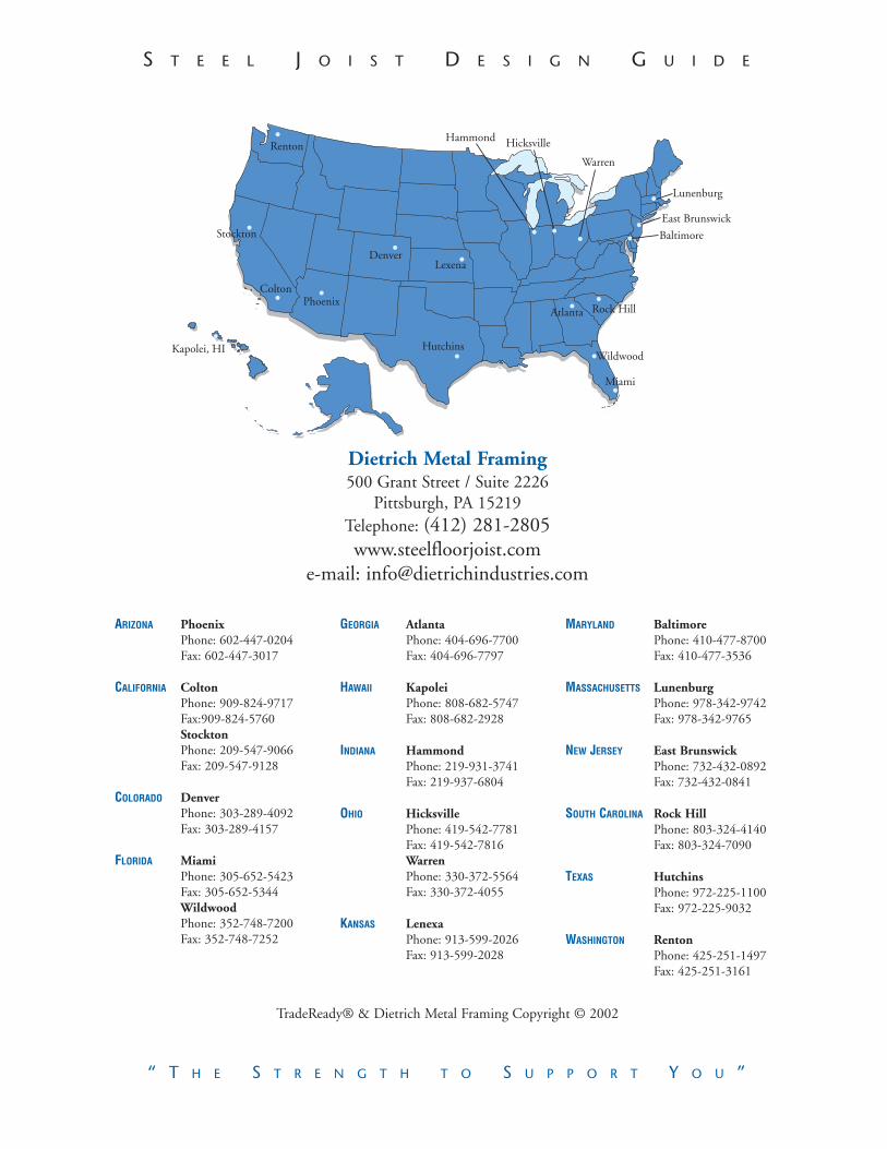
S T E E L J O I S T D E S I G N G U I D E
“ T H E S T R E N G T H T O S U P P O R T Y O U ”
ARIZONA PhoenixPhone: 602-447-0204Fax: 602-447-3017
CALIFORNIA ColtonPhone: 909-824-9717Fax:909-824-5760StocktonPhone: 209-547-9066Fax: 209-547-9128
COLORADO DenverPhone: 303-289-4092Fax: 303-289-4157
FLORIDA MiamiPhone: 305-652-5423Fax: 305-652-5344WildwoodPhone: 352-748-7200Fax: 352-748-7252
GEORGIA AtlantaPhone: 404-696-7700Fax: 404-696-7797
HAWAII KapoleiPhone: 808-682-5747Fax: 808-682-2928
INDIANA HammondPhone: 219-931-3741Fax: 219-937-6804
OHIO HicksvillePhone: 419-542-7781Fax: 419-542-7816WarrenPhone: 330-372-5564Fax: 330-372-4055
KANSAS LenexaPhone: 913-599-2026Fax: 913-599-2028
MARYLAND BaltimorePhone: 410-477-8700Fax: 410-477-3536
MASSACHUSETTS LunenburgPhone: 978-342-9742Fax: 978-342-9765
NEW JERSEY East BrunswickPhone: 732-432-0892Fax: 732-432-0841
SOUTH CAROLINA Rock HillPhone: 803-324-4140Fax: 803-324-7090
TEXAS HutchinsPhone: 972-225-1100Fax: 972-225-9032
WASHINGTON RentonPhone: 425-251-1497Fax: 425-251-3161
Dietrich Metal Framing500 Grant Street / Suite 2226
Pittsburgh, PA 15219Telephone: (412) 281-2805www.steelfloorjoist.com
e-mail: [email protected]
TradeReady® & Dietrich Metal Framing Copyright © 2002
68/02 DIETRICHTradeReady® Design Guide


