Embed Size (px)
Citation preview
Copyright ASHRAE Provided by IHS under license with ASHRAE Licensee=Kellogg Brown & Root Jakarta /3262700002, User=Rohana, Mumuh
Not for Resale, 09/09/2009 18:54:17 MDTNo reproduction or networking permitted without license from IHS
--`,,``,`,,,`,,`,````,`,`,,,,``,-`-`,,`,,`,`,,`---
HVAC
SimplifiedSolutions Manual
© 2006, American Society of Heating, Refrigerating and Air-Conditioning Engineers, Inc.(www.ashrae.org). HVAC Simplified Solutions Manual. For personal use only. Additional reproduc-tion, distribution, or transmission in either print or digital form is not permitted without ASHRAE'sprior written permission.
Copyright ASHRAE Provided by IHS under license with ASHRAE Licensee=Kellogg Brown & Root Jakarta /3262700002, User=Rohana, Mumuh
Not for Resale, 09/09/2009 18:54:17 MDTNo reproduction or networking permitted without license from IHS
--`,,``,`,,,`,,`,````,`,`,,,,``,-`-`,,`,,`,`,,`---

About the Author
Stephen P. Kavanaugh, PhD, Fellow ASHRAE, has been a professor of mechanical engineering at The Univer-sity of Alabama since 1985, where he teaches HVAC and is faculty advisor for the ASHRAE Student Chapter as wellas a Habitat for Humanity Student Affiliate.
Kavanaugh is co-author of Ground-Source Heat Pumps—Design of Geothermal Systems for Commercial andInstitutional Buildings, published by ASHRAE in 1997. He has presented over 100 engineering seminars for morethan 2,500 designers on the topics of energy efficiency, ground-source heat pumps, and HVAC. He maintains the Website www.geokiss.com, where there is more information about HVAC and ground-source heat pump design tools.
He is past chair and current handbook subcommittee chair of ASHRAE Technical Committee 6.8, GeothermalEnergy, as well as past chair of ASHRAE Technical Committee 9.4, Applied Heat Pumps and Heat Recovery.
Kavanaugh is also a Fellow of the American Society of Mechanical Engineers and a board member and pastpresident of Habitat for Humanity—Tuscaloosa.
Any updates/errata to this publication will be posted on the
ASHRAE Web site at www.ashrae.org/publicationupdates.
Copyright ASHRAE Provided by IHS under license with ASHRAE Licensee=Kellogg Brown & Root Jakarta /3262700002, User=Rohana, Mumuh
Not for Resale, 09/09/2009 18:54:17 MDTNo reproduction or networking permitted without license from IHS
--`,,``,`,,,`,,`,````,`,`,,,,``,-`-`,,`,,`,`,,`---
HVAC
SimplifiedSolutions Manual
Stephen P. Kavanaugh
American Society of Heating, Refrigeratingand Air-Conditioning Engineers, Inc.
Copyright ASHRAE Provided by IHS under license with ASHRAE Licensee=Kellogg Brown & Root Jakarta /3262700002, User=Rohana, Mumuh
Not for Resale, 09/09/2009 18:54:17 MDTNo reproduction or networking permitted without license from IHS
--`,,``,`,,,`,,`,````,`,`,,,,``,-`-`,,`,,`,`,,`---
ISBN 978-1-933742-09-0
©2006 American Society of Heating, Refrigeratingand Air-Conditioning Engineers, Inc.
1791 Tullie Circle, NEAtlanta, GA 30329
www.ashrae.org
All rights reserved.
Printed in the United States of America
ASHRAE has compiled this publication with care, but ASHRAE has not investigated, and ASHRAE expressly disclaimsany duty to investigate, any product, service, process, procedure, design, or the like that may be described herein. Theappearance of any technical data or editorial material in this publication does not constitute endorsement, warranty, orguaranty by ASHRAE of any product, service, process, procedure, design, or the like. ASHRAE does not warrant thatthe information in the publication is free of errors, and ASHRAE does not necessarily agree with any statement or opin-ion in this publication. The entire risk of the use of any information in this publication is assumed by the user.
No part of this book may be reproduced without permission in writing from ASHRAE, except by a reviewer who mayquote brief passages or reproduce illustrations in a review with appropriate credit; nor may any part of this book be repro-duced, stored in a retrieval system, or transmitted in any way or by any means—electronic, photocopying, recording,or other—without permission in writing from ASHRAE.
ASHRAE STAFF
SPECIAL PUBLICATIONS
Mildred GeshwilerEditor
Christina HelmsAssociate Editor
Cindy Sheffield MichaelsAssistant Editor
Michshell PhillipsAdministrative Assistant
PUBLISHING SERVICES
David SoltisManager
Tracy BeckerGraphic Applications Specialist
Jayne JacksonPublication Traffic Administrator
PUBLISHER
W. Stephen Comstock
Copyright ASHRAE Provided by IHS under license with ASHRAE Licensee=Kellogg Brown & Root Jakarta /3262700002, User=Rohana, Mumuh
Not for Resale, 09/09/2009 18:54:17 MDTNo reproduction or networking permitted without license from IHS
--`,,``,`,,,`,,`,````,`,`,,,,``,-`-`,,`,,`,`,,`---
v
Contents
Author’s Note to Users. . . . . . . . . . . . . . . . . . . . . . . . . . . . . . . . . . . . . . . . . . . . . . . . . . . . . . . . . . . . . . . . . . . . . . . . . vii
Nomenclature—HVAC Terms, Abbreviations, and Subscripts . . . . . . . . . . . . . . . . . . . . . . . . . . . . . . . . . . . . . . . . . . .ix
Solutions to Chapter 2—HVAC Fundamentals: Refrigeration . . . . . . . . . . . . . . . . . . . . . . . . . . . . . . . . . . . . . . . . . . . 1
Solutions to Chapter 3—HVAC Fundamentals: Heat Transfer . . . . . . . . . . . . . . . . . . . . . . . . . . . . . . . . . . . . . . . . . . . 5
Solutions to Chapter 4—HVAC Fundamentals: Psychrometrics . . . . . . . . . . . . . . . . . . . . . . . . . . . . . . . . . . . . . . . . . 11
Solutions to Chapter 5—HVAC Equipment, Systems, and Selection . . . . . . . . . . . . . . . . . . . . . . . . . . . . . . . . . . . . . 17
Solutions to Chapter 6—Comfort, Air Quality, and Climatic Data . . . . . . . . . . . . . . . . . . . . . . . . . . . . . . . . . . . . . . . 25
Solutions to Chapter 7—Heat and Moisture Flow in Buildings . . . . . . . . . . . . . . . . . . . . . . . . . . . . . . . . . . . . . . . . . 29
Solutions to Chapter 8—Cooling Load and Heating Loss Calculations and Analysis . . . . . . . . . . . . . . . . . . . . . . . . 35
Solutions to Chapter 9—Air Distribution System Design . . . . . . . . . . . . . . . . . . . . . . . . . . . . . . . . . . . . . . . . . . . . . . 41
Solutions to Chapter 10—Water Distribution System Design . . . . . . . . . . . . . . . . . . . . . . . . . . . . . . . . . . . . . . . . . . . 47
Solutions to Chapter 11—Motors, Lighting, and Controls . . . . . . . . . . . . . . . . . . . . . . . . . . . . . . . . . . . . . . . . . . . . . 51
Solutions to Chapter 12—Energy, Costs, and Economics . . . . . . . . . . . . . . . . . . . . . . . . . . . . . . . . . . . . . . . . . . . . . . 55
Copyright ASHRAE Provided by IHS under license with ASHRAE Licensee=Kellogg Brown & Root Jakarta /3262700002, User=Rohana, Mumuh
Not for Resale, 09/09/2009 18:54:17 MDTNo reproduction or networking permitted without license from IHS
--`,,``,`,,,`,,`,````,`,`,,,,``,-`-`,,`,,`,`,,`---

Copyright ASHRAE Provided by IHS under license with ASHRAE Licensee=Kellogg Brown & Root Jakarta /3262700002, User=Rohana, Mumuh
Not for Resale, 09/09/2009 18:54:17 MDTNo reproduction or networking permitted without license from IHS
--`,,``,`,,,`,,`,````,`,`,,,,``,-`-`,,`,,`,`,,`---

vii
Author’s Note to Users
Several of the solutions in this manual incorporate the use of the spreadsheet pro-grams that are provided with HVAC Simplified, such as E-Pipelator.xls, E-Ductulator.xls,HVACSysEff.xls, PsychProcess.xls, or TideLoad.xls. These programs are updated period-ically; the most current version can be obtained for free from the ASHRAE Web site atwww.ashrae.org/publicationupdates. The solutions in this text correspond to the 2006 ver-sions of these programs.
Copyright ASHRAE Provided by IHS under license with ASHRAE Licensee=Kellogg Brown & Root Jakarta /3262700002, User=Rohana, Mumuh
Not for Resale, 09/09/2009 18:54:17 MDTNo reproduction or networking permitted without license from IHS
--`,,``,`,,,`,,`,````,`,`,,,,``,-`-`,,`,,`,`,,`---

Copyright ASHRAE Provided by IHS under license with ASHRAE Licensee=Kellogg Brown & Root Jakarta /3262700002, User=Rohana, Mumuh
Not for Resale, 09/09/2009 18:54:17 MDTNo reproduction or networking permitted without license from IHS
--`,,``,`,,,`,,`,````,`,`,,,,``,-`-`,,`,,`,`,,`---
ix
Nomenclature—HVAC Terms,
Abbreviations, and Subscripts
AC alternating current, air cooled, or air-con-ditioning
adp apparatus dew pointADPI Air Diffusion Performance IndexASD adjustable-speed drive (a.k.a. variable-
speed drive, VSD)bhp, BHP brake horsepowerBtu/h heat rate unit (British thermal units per
hour)c coolingC loss coefficient (duct fittings)Cv flow coefficient (flow in gpm that results
in Δp = 1.0 psi)CF correction factorCFC chlorofluorocarbon (refrigerants)cfm cubic feet per minute (airflow rate)CLF cooling load factorCLTD cooling load temperature difference (°F)COP coefficient of performance (watts/watt)Δ delta (difference)Δh, ΔH differential headΔp, ΔP differential pressureD diameterdB decibel (sound power or pressure) or dry
bulb (temperature)db, DB dry bulb (temperature)dp dew point or differential pressureE energy (electrical ≡ kWh or thermal ≡ Btu)EER energy efficiency ratio (Btu/W·h or
MBtu/kWh)ESP external static pressure (in. of water)f frequency (Hz, cycles per second)FCU fan-coil unitFPVAV fan-powered variable air volumeft feet (distance or unit of head [ft of water])
gpm gallons per minuteη efficiencyh heating (Btu/h, kW), head of liquid (ft),
specific enthalpy (Btu/lb), heat transfercoefficient (Btu/h·ft2⋅°F)
H heat (Btu, J); enthalpy (Btu)HDPE high-density polyethylene (piping material)HRU, hru heat recovery unithp, HP unit of power (horsepower = 0.746 kW) or
heat pumpHVAC heating, ventilating, air-conditioningHz frequency unit (cycles per second)IAT (ti) indoor air temperatureK turbine flow meter constant (cycles per
gallon)kW kilowatt (unit of power or heat rate)kWh kilowatt-hour (unit of electrical energy)kW/ton electrical demand per unit cooling capac-
ity (kWrefrig./kWelect.)L, l latent heat or literLp sound pressure level (dB)Lw sound power level (dB)LMTD log-mean temperature difference (°F)MBtu/h heat rate unit (British thermal units per
hour × 1000)MERV minimum efficiency reporting values (for
air filters)μ fluid viscosity (lb/ft·s)NC noise criteriaOA outside air (a.k.a. ventilation air)OAT (to) outdoor air temperatureODP ozone depletion potentialpsi pounds per square inch (unit of pressure)psia pounds per square inch, absolutepsig pounds per square inch, gage
Copyright ASHRAE Provided by IHS under license with ASHRAE Licensee=Kellogg Brown & Root Jakarta /3262700002, User=Rohana, Mumuh
Not for Resale, 09/09/2009 18:54:17 MDTNo reproduction or networking permitted without license from IHS
--`,,``,`,,,`,,`,````,`,`,,,,``,-`-`,,`,,`,`,,`---
HVAC Simplified Solutions Manual
x
q heat rate (Btu/h or kW)Q volumetric flow rate (gpm, cfm, Lps, m3/s)R thermal resistance (a.k.a. R-value ≡
h·°F·ft2/Btu, °C·m2/W)Ra gas constant for air (ft·lbf/lbm·°F)Re Reynolds number (Re = ρDV/μ)RH relative humidity (%)RTU rooftop unitrpm, RPM revolutions per minuteρ density (lb/ft3)s specific entropy (Btu/lb·°F)S entropy (Btu/°F) SC shade coefficientSCL solar cooling load factor (Btu/h·ft2)SHR sensible heat ratiot, T temperature (°F, °C)TC total cooling (capacity)
TH total heating (capacity)ton cooling capacity (12,000 Btu/h, rate
required to freeze 2000 lb of water (32°F)in 24 hours)
TP total pressure (also p)TSP total static pressure (also ps)u specific internal energy (Btu/lb)U internal energy (Btu)V velocity (fps, fpm, m/s) and in some
cases volumetric airflow (ASHRAEStandard 62.1)
VAV variable air volume (airflow rate)VSD variable-speed drive (a.k.a. ASD)w, W power (kW)wb, WB wet bulb (temperature)w.c. water column (inches of water head)x mole fraction
Copyright ASHRAE Provided by IHS under license with ASHRAE Licensee=Kellogg Brown & Root Jakarta /3262700002, User=Rohana, Mumuh
Not for Resale, 09/09/2009 18:54:17 MDTNo reproduction or networking permitted without license from IHS
--`,,``,`,,,`,,`,````,`,`,,,,``,-`-`,,`,,`,`,,`---
Solutions to Chapter 2—
HVAC Fundamentals: Refrigeration
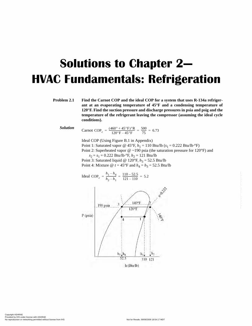
Problem 2.1 Find the Carnot COP and the ideal COP for a system that uses R-134a refriger-ant at an evaporating temperature of 45°F and a condensing temperature of120°F. Find the suction pressure and discharge pressures in psia and psig and thetemperature of the refrigerant leaving the compressor (assuming the ideal cycleconditions).
SolutionCarnot
Ideal COP (Using Figure B.1 in Appendix)Point 1: Saturated vapor @ 45°F, h1 = 110 Btu/lb (s1 = 0.222 Btu/lb·°F)Point 2: Superheated vapor @ ~190 psia (the saturation pressure for 120°F) and
s2 = s1 = 0.222 Btu/lb·°F, h2 = 121 Btu/lbPoint 3: Saturated liquid @ 120°F, h3 = 52.5 Btu/lbPoint 4: Mixture @ t = 45°F and h4 = h3 = 52.5 Btu/lb
Ideal
COPc460° 45°F+( )°R120°F 45°F–
------------------------------------------50075--------- 6.73= = =
COPc
h1 h4–
h2 h1–
-----------------110 52.5–
121 110–
------------------------- 5.2= = =
Copyright ASHRAE Provided by IHS under license with ASHRAE Licensee=Kellogg Brown & Root Jakarta /3262700002, User=Rohana, Mumuh
Not for Resale, 09/09/2009 18:54:17 MDTNo reproduction or networking permitted without license from IHS
--`,,``,`,,,`,,`,````,`,`,,,,``,-`-`,,`,,`,`,,`---
HVAC Simplified Solutions Manual
2
Problem 2.2 A scroll compressor (Table 2.3) with R-134a refrigerant operates with a 45°Fevaporating temperature and a 120°F discharge temperature. Find the coolingcapacity (20°F suction superheat and 15°F liquid subcooling), compressor inputpower, EER, suction pressure, and discharge pressure (psig).
Solution @ te = 45°F, tc = 120°F, SH = 20°F, and SC = 15°Fqr = 28.9 MBtu/h (25,900 Btu/h), wc = 2.25 kW (2,250 W)EER = qc/wc = 28.9/2.25 = 12.8 MBtu/kWh (= 28,900/2250 = 12.8 Btu/Wh)Interpolating between P = 50 psia @ 40.3°F and P = 75 psia @ 62.2°F to P @ 45°FP (suction) ≈ 55.4 psia = 40.7 psigInterpolating between P = 175 psia @ 115.8°F and P = 200 psia @ 125.3°F to
P @ 120°FP (discharge) ≈ 186 psia = 171.3 psig
Problem 2.3 What increase in capacity and EER can be expected if the superheat is loweredto 10°F and the condensing temperature is lowered to 100°F? What is the disad-vantage of doing this?
Solution @ te = 45°F, tc = 100°F, SH = 20°F, and SC = 15°Fqr = 32.3 MBtu/h, wc = 1.77 kW (@ SH = 20°F)qr (@ SH = 10°F) = 32.3 MBtu/h × (ρ @ SH = 10°F/ρ @ SH = 20°F)
= 32.3 MBtu/h × (ρ @ p ≈ 55 psia and t = 55°F/ρ @ p ≈ 55 psia and t = 65°F)= 32.3 MBtu/h × (1.11 lb/ft3 ÷ 1.09 lb/ft3) = 32.8 MBtu/h
EER = 32.8 ÷ 1.77 = 18.5 Btu/Wh
This represents a 13% increase in capacity and a 45% increase in efficiency. The dis-advantage of doing this is that the condenser will most likely have to be cooled withwater to lower the temperature to 100°F, and the 10°F lower superheat provides asmaller margin of error to prevent liquid refrigerant from entering the compressor.
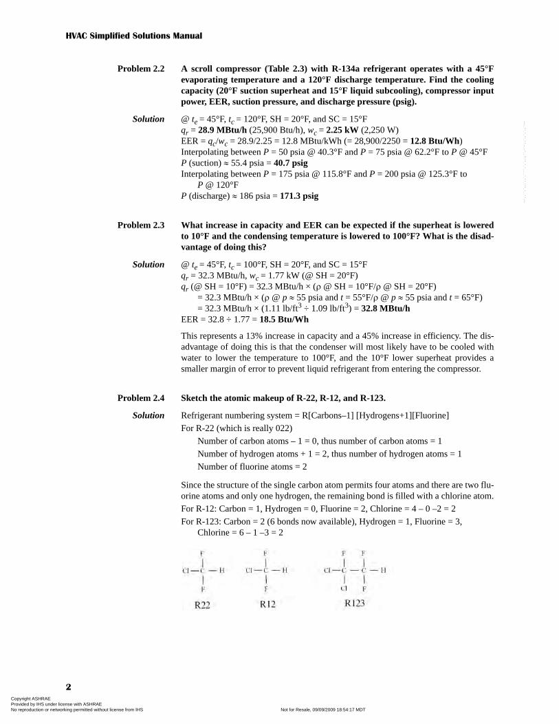
Problem 2.4 Sketch the atomic makeup of R-22, R-12, and R-123.
Solution Refrigerant numbering system = R[Carbons–1] [Hydrogens+1][Fluorine]For R-22 (which is really 022)
Number of carbon atoms – 1 = 0, thus number of carbon atoms = 1Number of hydrogen atoms + 1 = 2, thus number of hydrogen atoms = 1Number of fluorine atoms = 2
Since the structure of the single carbon atom permits four atoms and there are two flu-orine atoms and only one hydrogen, the remaining bond is filled with a chlorine atom.For R-12: Carbon = 1, Hydrogen = 0, Fluorine = 2, Chlorine = 4 – 0 –2 = 2For R-123: Carbon = 2 (6 bonds now available), Hydrogen = 1, Fluorine = 3,
Chlorine = 6 – 1 –3 = 2
Copyright ASHRAE Provided by IHS under license with ASHRAE Licensee=Kellogg Brown & Root Jakarta /3262700002, User=Rohana, Mumuh
Not for Resale, 09/09/2009 18:54:17 MDTNo reproduction or networking permitted without license from IHS
--`,,``,`,,,`,,`,````,`,`,,,,``,-`-`,,`,,`,`,,`---
Chapter 2—HVAC Fundamentals: Refrigeration
3
Problem 2.5 How can you determine if a refrigerant has chlorine in its structure from theR-xxx designation?
Solution If the R number of the refrigerant has only two digits (which means the first digit ofthe three-digit designation is 0), the sum of the remaining two numbers [(H + 1) and(F)] must be 5 to ensure chlorine is not present. If the first digit of the three-digit des-ignation is 1, the sum of the remaining two numbers [(H + 1) and (F)] must be 7 toensure chlorine is not present.
Problem 2.6 Compare the ideal COP of R-134a and R-22 at an evaporating temperature of40°F with 20°F superheat and a condensing temperature of 120°F with 15°F sub-cooling with the actual compressor COPs calculated from the manufacturer’sperformance tables.
Solution For R-134a using the P-h diagram (Figure B.1):@ te = 40°F (~50 psia) and SH = 20°F, t1 = 60°F and h1 = 113 Btu/lbTo find point 2, follow a line of constant entropy (s) to p =190 psia (saturated
pressure for tc = 120°F), h2 = 126 Btu/lb.To find point 3, follow a line of constant pressure (p = 190 psia) to the left, cross
the saturated liquid line, and go to a point 15°F below the saturated tempera-ture (120°F), or t3 = 105°F, h3 = 47 Btu/lb.
To find point 4, follow a line of constant enthalpy (h) downward to te = 40°F (~50psia), h4 = h3 = 47 Btu/lb.
Ideal
From Table 2.3 @ te = 40°F and tc = 120°F, qr = 25.9 MBtu/h and wc = 2.27 kW.Thus, EER = 25.9 ÷ 2.27 = 11.4 MBtu/kWh = 11.4 Btu/Wh andCOP = EER ÷ 3.412 Btu/Wh = 11.4 Btu/Wh ÷ 3.412 Btu/Wh = 3.34.
For R-22, using the P-h diagram (Figure B.2):Point 1: (te = 40°F), p1 ≈ 83 psia, t1 = 60°F, and h1 = 111 Btu/lb.Point 2: (tc = 120°F), p2 ≈ 275 psia, t2 ≈ 160°F, and h2 = 124 Btu/lb.Point 3: (tc = 120°F), p3 ≈ 275 psia, t3 = 105°F, and h3 = 42 Btu/lb.Point 4: t4 = te = 40°F, p4 = p1 ≈ 83 psia, h4 = h3 = 42 Btu/lb
Ideal
From Table 2.4 @ te = 40°F and tc = 120°F, qr = 32.4 MBtu/h and wc = 2.74 kW.Thus, EER = 32.4 ÷ 2.74 = 11.8 MBtu/kWh = 11.8 /Wh andCOP = EER ÷ 3.412 Btu/Wh = 11.8 Btu/Wh ÷ 3.412 Btu/Wh = 3.47.
Problem 2.7 A set of pressure gauges on a manifold (see figure in “Refrigerant Charging” insertabove) read 35 psig and a thermometer placed in close contact with the compres-sor inlet reads 67°F. The discharge pressure is 200 psig with an outdoor tempera-ture of 95°F, and the refrigerant is R-134a. Is this system properly charged? If not,what range of temperature should be expected for these pressures?
Solution @ 35 psig, te = 40°F for R-134aCheck @ p = 14.7 + 35 = 49.7 psia, te ≈ 40°F (as shown in Table 2.1)Superheat = t1 – te = 67°F – 40°F = 27°F
The unit appears to be undercharged since proper operation typically dictates that thesuperheat be in the 10°F to 20°F range when nearly fully loaded, as indicated with the95°F outdoor air temperature.
COPc
h1 h4–
h2 h1–
-----------------113 47–
126 113–
------------------------ 5.1= = =
COPc
h1 h4–
h2 h1–
-----------------111 42–
124 111–
------------------------ 5.3= = =
Copyright ASHRAE Provided by IHS under license with ASHRAE Licensee=Kellogg Brown & Root Jakarta /3262700002, User=Rohana, Mumuh
Not for Resale, 09/09/2009 18:54:17 MDTNo reproduction or networking permitted without license from IHS
--`,,``,`,,,`,,`,````,`,`,,,,``,-`-`,,`,,`,`,,`---
HVAC Simplified Solutions Manual
4
Problem 2.8 A manufacturer recommends that their R-22 equipment operate with a suctionpressure of 72 psig and a return gas temperature of 53°F with a specified air tem-perature (75°F) and flow rate (400 cfm/ton). What are the corresponding evapo-rating temperature and superheat?
Solution P1 = 72 psig = 84.7 psiaThe pressure gauge shown in Figure 2.12 indicates te @ 72 psig ≈ 43°F.Thus, SH = t1 – te = 53°F – 43°F = 10°F.
Problem 2.9 With regard to the use of refrigerant mixtures as substitutes for CFCs, explainthe difference between azeotropes and zeotropes. What is “glide”?
Solution Azeotropes are refrigerant mixtures that behave as pure substances. When the refriger-ant exists in a mixture of vapor and liquid, the lines of constant temperature are paral-lel with the lines of constant pressure with changing vapor-liquid fraction on a P-hdiagram. Both lines are horizontal in the dome-shaped region of the chart bounded bythe saturated liquid and saturated vapor lines. Zeotropes are refrigerant mixtureswhose components evaporate and condense at a “gliding” temperature that dependson both the pressure and vapor-liquid fractions. The lines of constant temperaturewithin the “vapor dome” region of a P-h diagram are not perfectly horizontal.
Problem 2.10 A refrigerant has an ASHRAE Standard 34 designation of A2 and B2. Whatdoes this mean? It also has an ODP of 0.75. Is this good, acceptable, or unac-ceptable?
Solution The A2 designation indicates a low level of toxicity (A being nontoxic and B beingtoxic). The value of 2 indicates a low lower flammability limit (LFL) with 1 being nopropagation in air and 3 having a high LFL. An ODP (ozone depletion potential) of0.75 is unacceptable since many of the CFCs that have been banned have ODPsaround 1.0.
Copyright ASHRAE Provided by IHS under license with ASHRAE Licensee=Kellogg Brown & Root Jakarta /3262700002, User=Rohana, Mumuh
Not for Resale, 09/09/2009 18:54:17 MDTNo reproduction or networking permitted without license from IHS
--`,,``,`,,,`,,`,````,`,`,,,,``,-`-`,,`,,`,`,,`---
Solutions to Chapter 3—
HVAC Fundamentals: Heat Transfer
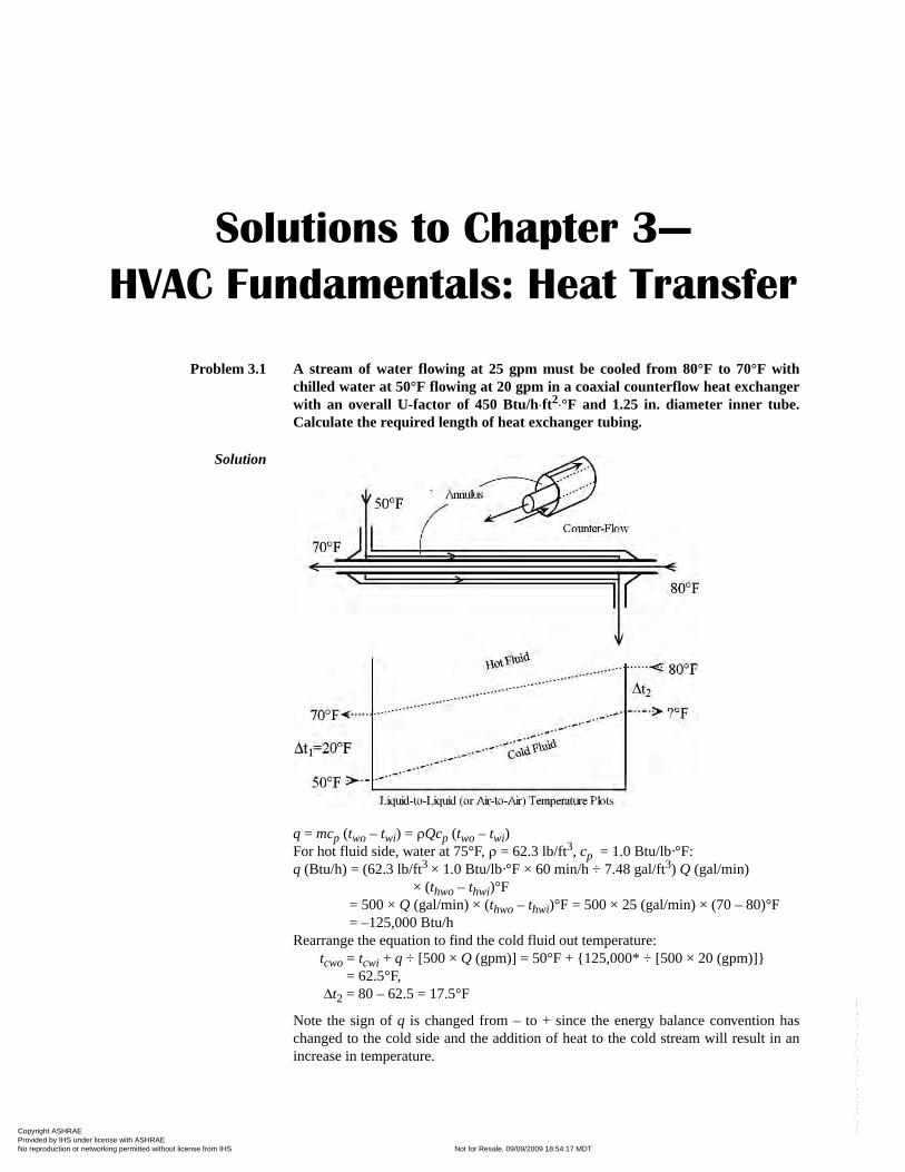
Problem 3.1 A stream of water flowing at 25 gpm must be cooled from 80°F to 70°F withchilled water at 50°F flowing at 20 gpm in a coaxial counterflow heat exchangerwith an overall U-factor of 450 Btu/h⋅ft2⋅°F and 1.25 in. diameter inner tube.Calculate the required length of heat exchanger tubing.
Solution
q = mcp (two – twi) = ρQcp (two – twi)For hot fluid side, water at 75°F, ρ = 62.3 lb/ft3, cp = 1.0 Btu/lb·°F:q (Btu/h) = (62.3 lb/ft3 × 1.0 Btu/lb·°F × 60 min/h ÷ 7.48 gal/ft3) Q (gal/min)
× (thwo – thwi)°F= 500 × Q (gal/min) × (thwo – thwi)°F = 500 × 25 (gal/min) × (70 – 80)°F= –125,000 Btu/h
Rearrange the equation to find the cold fluid out temperature:tcwo = tcwi + q ÷ [500 × Q (gpm)] = 50°F + {125,000* ÷ [500 × 20 (gpm)]}
= 62.5°F,Δt2 = 80 – 62.5 = 17.5°F
Note the sign of q is changed from – to + since the energy balance convention haschanged to the cold side and the addition of heat to the cold stream will result in anincrease in temperature.
Copyright ASHRAE Provided by IHS under license with ASHRAE Licensee=Kellogg Brown & Root Jakarta /3262700002, User=Rohana, Mumuh
Not for Resale, 09/09/2009 18:54:17 MDTNo reproduction or networking permitted without license from IHS
--`,,``,`,,,`,,`,````,`,`,,,,``,-`-`,,`,,`,`,,`---
HVAC Simplified Solutions Manual
6
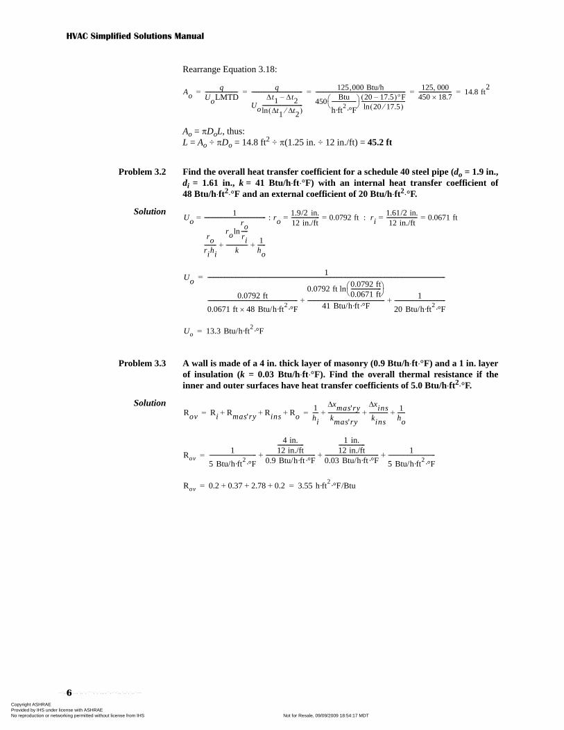
Rearrange Equation 3.18:
Ao = πDoL, thus:L = Ao ÷ πDo = 14.8 ft2 ÷ π(1.25 in. ÷ 12 in./ft) = 45.2 ft
Problem 3.2 Find the overall heat transfer coefficient for a schedule 40 steel pipe (do = 1.9 in.,di = 1.61 in., k = 41 Btu/h⋅ft⋅°F) with an internal heat transfer coefficient of48 Btu/h⋅ft2⋅°F and an external coefficient of 20 Btu/h⋅ft2⋅°F.
Solution
Problem 3.3 A wall is made of a 4 in. thick layer of masonry (0.9 Btu/h⋅ft⋅°F) and a 1 in. layerof insulation (k = 0.03 Btu/h⋅ft⋅°F). Find the overall thermal resistance if theinner and outer surfaces have heat transfer coefficients of 5.0 Btu/h⋅ft2⋅°F.
Solution
Aoq
UoLMTD-------------------------
q
Uo
Δt1 Δt2–
ln t1Δ t2Δ⁄( )-------------------------------
---------------------------------------
125,000 Btu/h
450Btu
h·ft2·°F
-------------------
⎝ ⎠⎛ ⎞ 20 17.5–( )°F
ln 20 17.5⁄( )----------------------------------
---------------------------------------------------------------------
125 000,450 18.7×------------------------- 14.8 ft
2= = = = =
Uo1
rorihi---------
rolnrori-----
k----------------
1ho------+ +
----------------------------------------------= : ro1.9/2 in.12 in./ft--------------------- 0.0792 ft= = : ri
1.61/2 in.12 in./ft----------------------- 0.0671 ft= =
Uo1
0.0792 ft
0.0671 ft 48 Btu/h·ft2·°F×
-----------------------------------------------------------------
0.0792 ft ln0.0792 ft0.0671 ft----------------------⎝ ⎠⎛ ⎞
41 Btu/h·ft·°F--------------------------------------------------------
1
20 Btu/h·ft2·°F
-------------------------------------+ +
----------------------------------------------------------------------------------------------------------------------------------------------------------------------------=
Uo 13.3 Btu/h·ft2·°F=
Rov Ri Rmas'ry Rins Ro+ + +1hi----
xmas'ryΔ
kmas'ry-----------------------
xinsΔ
kins--------------
1ho------+ + += =
Rov1
5 Btu/h·ft2·°F
----------------------------------
4 in.12 in./ft-------------------
0.9 Btu/h·ft·°F------------------------------------
1 in.12 in./ft-------------------
0.03 Btu/h·ft·°F---------------------------------------
1
5 Btu/h·ft2·°F
----------------------------------+ + +=
Rov 0.2 0.37 2.78 0.2+ + + 3.55 h·ft2·°F/Btu= =
Copyright ASHRAE Provided by IHS under license with ASHRAE Licensee=Kellogg Brown & Root Jakarta /3262700002, User=Rohana, Mumuh
Not for Resale, 09/09/2009 18:54:17 MDTNo reproduction or networking permitted without license from IHS
--`,,``,`,,,`,,`,````,`,`,,,,``,-`-`,,`,,`,`,,`---

Chapter 3—HVAC Fundamentals: Heat Transfer
7
Problem 3.4 Repeat problem 3.3 if an added layer of ½ in. plywood (0.2 Btu/h⋅ft⋅°F) covers50% of the wall and the remaining 50% is covered by ½ in. thick additional insu-lation.
Solution Based on 1 ft2 (Awall = 1.0 ft2) and rearranging Equation 3.16 to solve for Rov :
Problem 3.5 A condenser is to be fabricated from the heat exchanger tubing described inProblem 3.1 for a compressor that flows 950 lb/h of R-134a refrigerant. Find thetotal required heat transfer rate, the heat required to desuperheat the gas, andthe required length of tubing if the overall U-factor is 500 Btu/h⋅ft2⋅°F, the tem-perature leaving the compressor is 200°F, and the pressure is 185 psig. The con-denser exit is saturated liquid at 185 psig and the water temperatures enteringand leaving the condenser are 70°F and 80°F, respectively.
Solution Find refrigerant enthalpy at inlet (h2), saturated vapor (hsat), and outlet (h3). h2 is a superheated vapor @ 185 psig (~200 psia), h2 = 139 Btu/lb.For a saturated vapor @ 200 psia (125°F), hsat = 119 Btu/lb.For a saturated liquid @ 200 psia, hsat = h3 = 54 Btu/lb.
qr = mr(h2 – h3) = 950 lb/h × (139 – 54) Btu/lb = 80,750 Btu/h
Heat required to desuperheat:qr(ds) = mr(h2 – hsat) = 950 lb/h × (139 – 119) Btu/lb = 19,000 Btu/h
Heat required to condense from saturated vapor to saturated liquid:qr(cond) = mr(hsat – h3) = 950 lb/h × (119 – 54) Btu/lb = 61,750 Btu/h
To size condenser, break into two sections so that LMTD can be calculated for bothsections.
Rov Awall1
hiAwall-----------------
xmas'ryΔ
kmas'ryAwall---------------------------------
xinsΔ
kinsAwall-----------------------
xply&insΔ
0.5kplyAwall 0.5kinsAwall+
-------------------------------------------------------------------1
hoAwall------------------+ + + +
⎝ ⎠⎜ ⎟⎛ ⎞
=
Rov 1 ft2 1
5 Btu/h·ft2·°F 1 ft
2×
---------------------------------------------------
4 in.12 in./ft-------------------
0.9 Btu/h·ft·°F 1 ft2
×-----------------------------------------------------
1 in.12 in./ft-------------------
0.03 Btu/h·ft·°F 1 ft2
×--------------------------------------------------------+ +
⎝⎜⎜⎛
×=
0.5 in.12 in./ft-------------------
0.5 0.2 Btu/h·ft·°F1 ft2
0.5 0.03 Btu/h·ft·°F1 ft2
×+×------------------------------------------------------------------------------------------------------------------------------------
1
5 Btu/h·ft2·°F 1 ft
2×
---------------------------------------------------+
⎠⎟⎟⎞
+
Rov 0.2 0.37 2.78 0.36 0.2+ + + + 3.91 h·ft2·°F/Btu= =
Copyright ASHRAE Provided by IHS under license with ASHRAE Licensee=Kellogg Brown & Root Jakarta /3262700002, User=Rohana, Mumuh
Not for Resale, 09/09/2009 18:54:17 MDTNo reproduction or networking permitted without license from IHS
--`,,``,`,,,`,,`,````,`,`,,,,``,-`-`,,`,,`,`,,`---
HVAC Simplified Solutions Manual
8
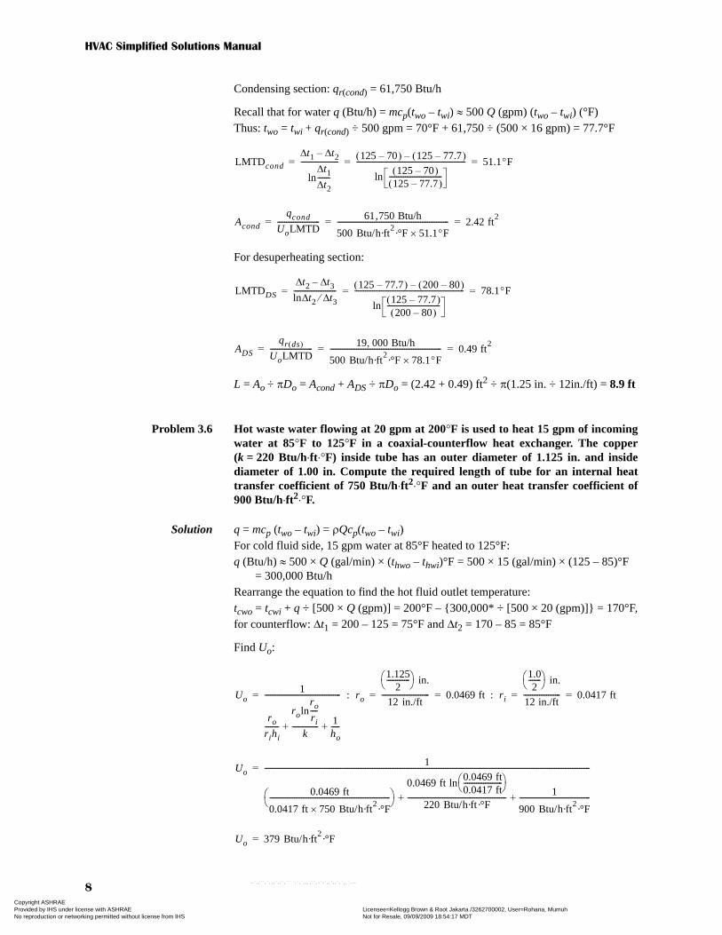
Condensing section: qr(cond) = 61,750 Btu/h
Recall that for water q (Btu/h) = mcp(two – twi) ≈ 500 Q (gpm) (two – twi) (°F)Thus: two = twi + qr(cond) ÷ 500 gpm = 70°F + 61,750 ÷ (500 × 16 gpm) = 77.7°F
For desuperheating section:
L = Ao ÷ πDo = Acond + ADS ÷ πDo = (2.42 + 0.49) ft2 ÷ π(1.25 in. ÷ 12in./ft) = 8.9 ft
Problem 3.6 Hot waste water flowing at 20 gpm at 200°F is used to heat 15 gpm of incomingwater at 85°F to 125°F in a coaxial-counterflow heat exchanger. The copper(k = 220 Btu/h⋅ft⋅°F) inside tube has an outer diameter of 1.125 in. and insidediameter of 1.00 in. Compute the required length of tube for an internal heattransfer coefficient of 750 Btu/h⋅ft2⋅°F and an outer heat transfer coefficient of900 Btu/h⋅ft2⋅°F.
Solution q = mcp (two – twi) = ρQcp(two – twi)For cold fluid side, 15 gpm water at 85°F heated to 125°F:q (Btu/h) ≈ 500 × Q (gal/min) × (thwo – thwi)°F = 500 × 15 (gal/min) × (125 – 85)°F
= 300,000 Btu/hRearrange the equation to find the hot fluid outlet temperature:tcwo = tcwi + q ÷ [500 × Q (gpm)] = 200°F – {300,000* ÷ [500 × 20 (gpm)]} = 170°F,for counterflow: Δt1 = 200 – 125 = 75°F and Δt2 = 170 – 85 = 85°F
Find Uo:
LMTDcond
t1Δ t2Δ–
lnt1Δ
t2Δ-------
---------------------125 70–( ) 125 77.7–( )–
ln125 70–( )
125 77.7–( )------------------------------
-------------------------------------------------------------- 51.1°F= = =
Acond
qcond
UoLMTD------------------------
61,750 Btu/h
500 Btu/h·ft2·°F 51.1°F×
--------------------------------------------------------------- 2.42 ft2
= = =
LMTDDS
t2Δ t3Δ–
ln t2 t3Δ⁄Δ------------------------
125 77.7–( ) 200 80–( )–
ln125 77.7–( )200 80–( )
------------------------------
-------------------------------------------------------------- 78.1°F= = =
ADS
qr ds( )
UoLMTD------------------------
19 000 Btu/h,
500 Btu/h·ft2·°F 78.1°F×
--------------------------------------------------------------- 0.49 ft2
= = =
Uo1
ro
rihi--------
rolnro
ri----
k---------------
1ho-----+ +
------------------------------------------- : ro
1.1252
-------------⎝ ⎠⎛ ⎞ in.
12 in./ft--------------------------- 0.0469 ft : ri
1.02-------⎝ ⎠⎛ ⎞ in.
12 in./ft--------------------- 0.0417 ft= = = = =
Uo1
0.0469 ft
0.0417 ft 750 Btu/h·ft2·°F×
--------------------------------------------------------------------⎝ ⎠⎛ ⎞
0.0469 ft ln0.0469 ft0.0417 ft----------------------⎝ ⎠⎛ ⎞
220 Btu/h·ft·°F--------------------------------------------------------
1
900 Btu/h·ft2·°F
----------------------------------------+ +
----------------------------------------------------------------------------------------------------------------------------------------------------------------------------------------=
Uo 379 Btu/h·ft2·°F=
Copyright ASHRAE Provided by IHS under license with ASHRAE Licensee=Kellogg Brown & Root Jakarta /3262700002, User=Rohana, Mumuh
Not for Resale, 09/09/2009 18:54:17 MDTNo reproduction or networking permitted without license from IHS
--`,,``,`,,,`,,`,````,`,`,,,,``,-`-`,,`,,`,`,,`---

Chapter 3—HVAC Fundamentals: Heat Transfer
9
Rearrange Equation 3.18:
Ao = πDoL, thus:L = Ao ÷ πDo = 9.96 ft2 ÷ π(1.125 in. ÷ 12 in./ft) = 33.8 ft
Aoq
UoLMTD------------------------
q
Uo
t1Δ t2Δ–
lnt1Δ
t2Δ-------⎝ ⎠⎛ ⎞
---------------------
-----------------------------300 000 Btu/h,
377 Btu/h·ft2·°F
75 85–( )°F
ln7585------⎝ ⎠⎛ ⎞
-----------------------------
----------------------------------------------------------------------300 000,
377 79.9×------------------------- 9.96 ft
2= = = = =
Copyright ASHRAE Provided by IHS under license with ASHRAE Licensee=Kellogg Brown & Root Jakarta /3262700002, User=Rohana, Mumuh
Not for Resale, 09/09/2009 18:54:17 MDTNo reproduction or networking permitted without license from IHS
--`,,``,`,,,`,,`,````,`,`,,,,``,-`-`,,`,,`,`,,`---

Copyright ASHRAE Provided by IHS under license with ASHRAE Licensee=Kellogg Brown & Root Jakarta /3262700002, User=Rohana, Mumuh
Not for Resale, 09/09/2009 18:54:17 MDTNo reproduction or networking permitted without license from IHS
--`,,``,`,,,`,,`,````,`,`,,,,``,-`-`,,`,,`,`,,`---
Solutions to Chapter 4—
HVAC Fundamentals: Psychrometrics
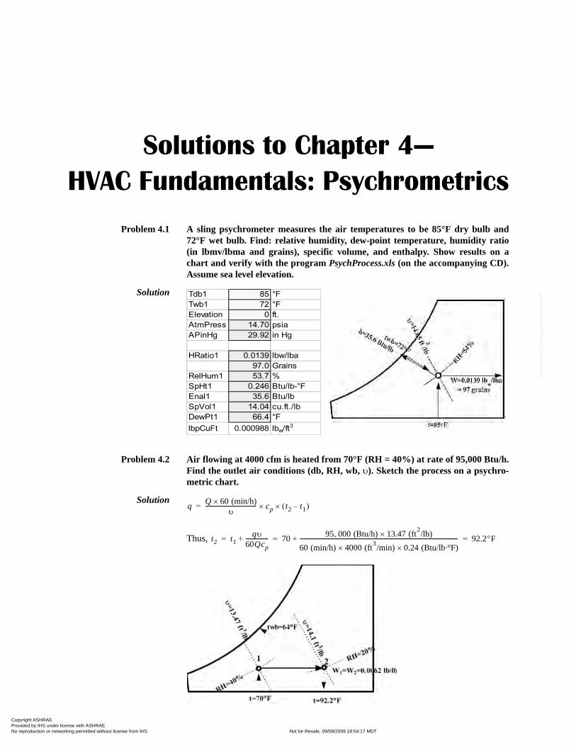
Problem 4.1 A sling psychrometer measures the air temperatures to be 85°F dry bulb and72°F wet bulb. Find: relative humidity, dew-point temperature, humidity ratio(in lbmv/lbma and grains), specific volume, and enthalpy. Show results on achart and verify with the program PsychProcess.xls (on the accompanying CD).Assume sea level elevation.
Solution
Problem 4.2 Air flowing at 4000 cfm is heated from 70°F (RH = 40%) at rate of 95,000 Btu/h.Find the outlet air conditions (db, RH, wb, υ). Sketch the process on a psychro-metric chart.
Solution
Thus,
Tdb1 85 °F
Twb1 72 °F
Elevation 0 ft.
AtmPress 14.70 psia
APinHg 29.92 in Hg
HRatio1 0.0139 lbw/lba
97.0 Grains
RelHum1 53.7 %
SpHt1 0.246 Btu/lb-°F
Enal1 35.6 Btu/lb
SpVol1 14.04 cu.ft./lb
DewPt1 66.4 °F
lbpCuFt 0.000988 lbw/ft3
qQ 60 (min/h)×
υ------------------------------------ cp× t2 t1–( )×=
t2 t1qυ
60Qcp----------------+ 70
95 000 (Btu/h), 13.47 (ft2/lb)×
60 (min/h) 4000 (ft3/min)× 0.24 (Btu/lb·°F)×
----------------------------------------------------------------------------------------------------------------+ 92.2°F= = =
Copyright ASHRAE Provided by IHS under license with ASHRAE Licensee=Kellogg Brown & Root Jakarta /3262700002, User=Rohana, Mumuh
Not for Resale, 09/09/2009 18:54:17 MDTNo reproduction or networking permitted without license from IHS
--`,,``,`,,,`,,`,````,`,`,,,,``,-`-`,,`,,`,`,,`---
HVAC Simplified Solutions Manual
12
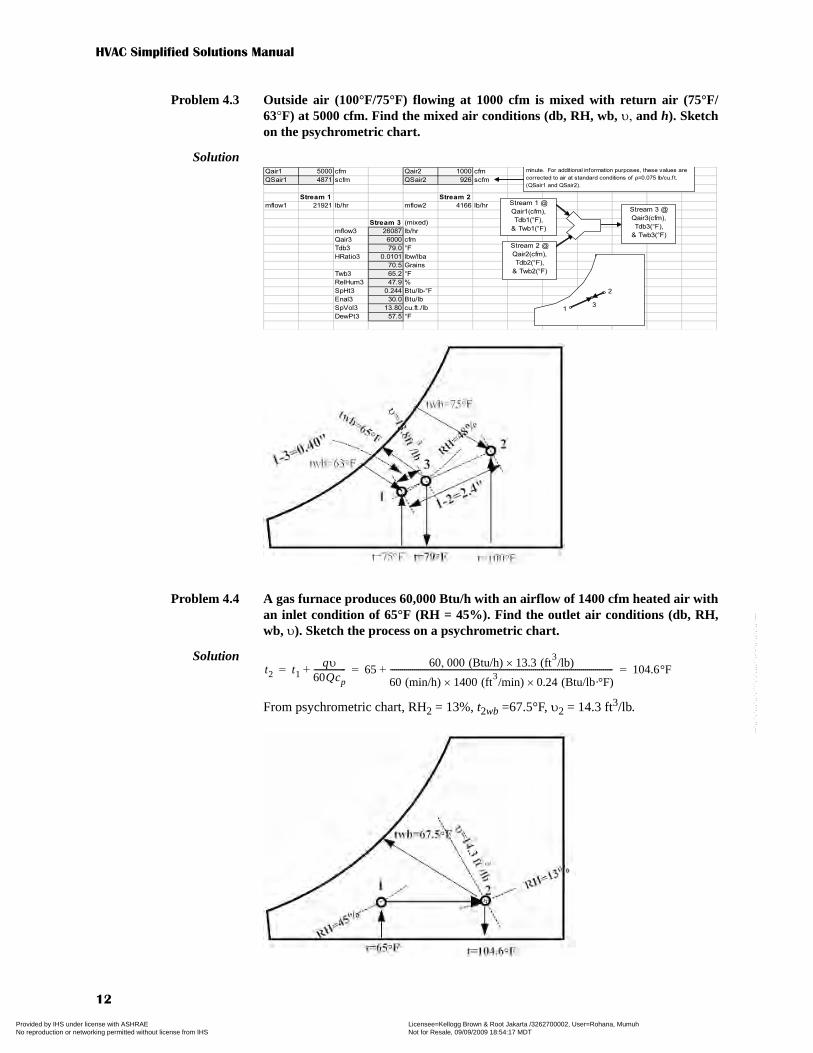
Problem 4.3 Outside air (100°F/75°F) flowing at 1000 cfm is mixed with return air (75°F/63°F) at 5000 cfm. Find the mixed air conditions (db, RH, wb, υ, and h). Sketchon the psychrometric chart.
Solution
Problem 4.4 A gas furnace produces 60,000 Btu/h with an airflow of 1400 cfm heated air withan inlet condition of 65°F (RH = 45%). Find the outlet air conditions (db, RH,wb, υ). Sketch the process on a psychrometric chart.
Solution
From psychrometric chart, RH2 = 13%, t2wb =67.5°F, υ2 = 14.3 ft3/lb.
Qair1 5000 cfm Qair2 1000 cfm
QSair1 4871 scfm QSair2 926 scfm
Stream 1 Stream 2
mflow1 21921 lb/hr mflow2 4166 lb/hr
Stream 3 (mixed)
mflow3 26087 lb/hr
Qair3 6000 cfm
Tdb3 79.0 °F
HRatio3 0.0101 lbw/lba
70.5 Grains
Twb3 65.2 °F
RelHum3 47.9 %
SpHt3 0.244 Btu/lb-°F
Enal3 30.0 Btu/lb
SpVol3 13.80 cu.ft./lb
DewPt3 57.5 °F
minute. For additional information purposes, these values are
corrected to air at standard conditions of ρ=0.075 lb/cu.ft.
(QSair1 and QSair2).
Stream 2 @
Qair2(cfm),
Tdb2(°F),
& Twb2(°F)
Stream 1 @
Qair1(cfm),
Tdb1(°F),
& Twb1(°F)
Stream 3 @
Qair3(cfm),
Tdb3(°F),
& Twb3(°F)
1
2
3
t2 t1qυ
60Qcp----------------+ 65
60 000 (Btu/h), 13.3 (ft3/lb)×
60 (min/h) 1400 (ft3/min)× 0.24 (Btu/lb·°F)×
----------------------------------------------------------------------------------------------------------------+ 104.6°F= = =
Copyright ASHRAE Provided by IHS under license with ASHRAE Licensee=Kellogg Brown & Root Jakarta /3262700002, User=Rohana, Mumuh
Not for Resale, 09/09/2009 18:54:17 MDTNo reproduction or networking permitted without license from IHS
--`,,``,`,,,`,,`,````,`,`,,,,``,-`-`,,`,,`,`,,`---

Chapter 4—HVAC Fundamentals: Psychrometrics
13
Problem 4.5 Outside air (95°F/75°F) flowing at 2500 cfm is mixed with return air (75°F/63°F)at 7500 cfm. Find the mixed air conditions (db, RH, wb, υ, and h). Sketch on thepsychrometric chart.
Solution
Point 3 is on a line drawn from point 1 to point 2 at a distance of 0.51 in. from point 1.Note that point 3 will be closer to the condition (point 1) with the larger flow rate.
From psychrometric chart, t3 = 79.8°F, t3wb = 66.5°F, RH3 = 49%, υ3 = 13.8 ft3/lb,h3 = 30.9 Btu/lb
Problem 4.6 A quantity of 1600 cfm of air at 80°F/67°F enters an evaporator coil with a 0.12bypass factor and a 45°F apparatus dew point. Find the outlet air conditions (db,wb, RH, h), the sensible cooling capacity, the latent cooling capacity, total coolingcapacity, and the SHR of the coil. Sketch on the psychrometric chart.
Solution Q = 1600 cfm, t1 = 80°F, t1wb = 67°F, tadp = 45°F, BF = 0.12t2 = BF(t1 – tadp) + tadp = 0.12(80 – 45) + 45 = 49.2°F
A line is drawn on the psychrometric chart from point 1 [80°F (db)/67°F (wb)] totadp = 45°F, which is located on the saturation (RH = 100%) line. Point 2 is located onthe intersection of this line and the line for t2 = 49.2°F.
From psychrometric chart, t2wb = 48°F, RH2 = 92%, h2 = 19.3 Btu/lb.
qs (Btu/h) ≈ 1.08 · Q (cfm) · (t2 – t1)°F = 1.08 · 1600 cfm · (80 – 49.2) = 53,200 Btu/hqL (Btu/h) ≈ 4680 · Q (cfm) · (W2 – W1) lbw/lba = 1.08 · 1600 cfm · (0.0110 – 0.007)
≈ 30,200 Btu/hq = qs + qL = 53,200 + 30,000 = 83,200 Btu/hSHRcoil = qs ÷ q = 53,200 ÷ 83,200 = 0.64
1 3– 1 2–
Q2
Q1 Q2+
-------------------- 2.05 in. 2500 cfm
7500 cfm 2500 cfm+
---------------------------------------------------- 0.51 in.= = =
Copyright ASHRAE Provided by IHS under license with ASHRAE Licensee=Kellogg Brown & Root Jakarta /3262700002, User=Rohana, Mumuh
Not for Resale, 09/09/2009 18:54:17 MDTNo reproduction or networking permitted without license from IHS
--`,,``,`,,,`,,`,````,`,`,,,,``,-`-`,,`,,`,`,,`---
HVAC Simplified Solutions Manual
14
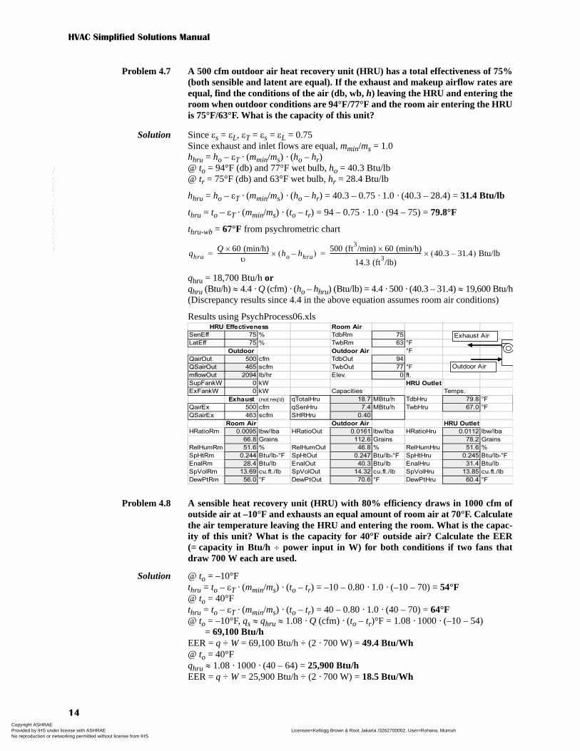
Problem 4.7 A 500 cfm outdoor air heat recovery unit (HRU) has a total effectiveness of 75%(both sensible and latent are equal). If the exhaust and makeup airflow rates areequal, find the conditions of the air (db, wb, h) leaving the HRU and entering theroom when outdoor conditions are 94°F/77°F and the room air entering the HRUis 75°F/63°F. What is the capacity of this unit?
Solution Since εs = εL, εT = εs = εL = 0.75Since exhaust and inlet flows are equal, mmin/ms = 1.0hhru = ho – εT · (mmin/ms) · (ho – hr)@ to = 94°F (db) and 77°F wet bulb, ho = 40.3 Btu/lb@ tr = 75°F (db) and 63°F wet bulb, hr = 28.4 Btu/lb
hhru = ho – εT · (mmin/ms) · (ho – hr) = 40.3 – 0.75 · 1.0 · (40.3 – 28.4) = 31.4 Btu/lb
thru = to – εT · (mmin/ms) · (to – tr) = 94 – 0.75 · 1.0 · (94 – 75) = 79.8°F
thru-wb = 67°F from psychrometric chart
qhru = 18,700 Btu/h orqhru (Btu/h) ≈ 4.4 · Q (cfm) · (ho – hhru) (Btu/lb) = 4.4 · 500 · (40.3 – 31.4) ≈ 19,600 Btu/h(Discrepancy results since 4.4 in the above equation assumes room air conditions)
Results using PsychProcess06.xls
Problem 4.8 A sensible heat recovery unit (HRU) with 80% efficiency draws in 1000 cfm ofoutside air at –10°F and exhausts an equal amount of room air at 70°F. Calculatethe air temperature leaving the HRU and entering the room. What is the capac-ity of this unit? What is the capacity for 40°F outside air? Calculate the EER(= capacity in Btu/h ÷ power input in W) for both conditions if two fans thatdraw 700 W each are used.
Solution @ to = –10°Fthru = to – εT · (mmin/ms) · (to – tr) = –10 – 0.80 · 1.0 · (–10 – 70) = 54°F@ to = 40°Fthru = to – εT · (mmin/ms) · (to – tr) = 40 – 0.80 · 1.0 · (40 – 70) = 64°F@ to = –10°F, qs ≈ qhru ≈ 1.08 · Q (cfm) · (to – tr)°F = 1.08 · 1000 · (–10 – 54)
= 69,100 Btu/hEER = q ÷ W = 69,100 Btu/h ÷ (2 · 700 W) = 49.4 Btu/Wh@ to = 40°Fqhru ≈ 1.08 · 1000 · (40 – 64) = 25,900 Btu/hEER = q ÷ W = 25,900 Btu/h ÷ (2 · 700 W) = 18.5 Btu/Wh
qhruQ 60 (min/h)×
υ------------------------------------ ho hhru–( )×
500 (ft3/min) 60 (min/h)×
14.3 (ft3/lb)
---------------------------------------------------------------- 40.3 31.4–( ) Btu/lb×= =
HRU Effectiveness Room Air
SenEff 75 % TdbRm 75
LatEff 75 % TwbRm 63 °F
Outdoor Outdoor Air °F
QairOut 500 cfm TdbOut 94
QSairOut 465 scfm TwbOut 77 °F
mflowOut 2094 lb/hr Elev. 0 ft.
SupFankW 0 kW HRU Outlet
ExFankW 0 kW Capacities Temps.
Exhaust (not req'd) qTotalHru 18.7 MBtu/h TdbHru 79.8 °F
QairEx 500 cfm qSenHru 7.4 MBtu/h TwbHru 67.0 °F
QSairEx 463 scfm SHRHru 0.40
Room Air Outdoor Air HRU Outlet
HRatioRm 0.0095 lbw/lba HRatioOut 0.0161 lbw/lba HRatioHru 0.0112 lbw/lba
66.8 Grains 112.6 Grains 78.2 Grains
RelHumRm 51.6 % RelHumOut 46.8 % RelHumHru 51.6 %
SpHtRm 0.244 Btu/lb-°F SpHtOut 0.247 Btu/lb-°F SpHtHru 0.245 Btu/lb-°F
EnalRm 28.4 Btu/lb EnalOut 40.3 Btu/lb EnalHru 31.4 Btu/lb
SpVolRm 13.69 cu.ft./lb SpVolOut 14.32 cu.ft./lb SpVolHru 13.85 cu.ft./lb
DewPtRm 56.0 °F DewPtOut 70.6 °F DewPtHru 60.4 °F
Outdoor Air
Exhaust Air
Copyright ASHRAE Provided by IHS under license with ASHRAE Licensee=Kellogg Brown & Root Jakarta /3262700002, User=Rohana, Mumuh
Not for Resale, 09/09/2009 18:54:17 MDTNo reproduction or networking permitted without license from IHS
--`,,``,`,,,`,,`,````,`,`,,,,``,-`-`,,`,,`,`,,`---

Chapter 4—HVAC Fundamentals: Psychrometrics
15
Problem 4.9 A quantity of 2500 cfm of air at 82°F/70°F enters an evaporator coil with a 0.08bypass factor and a 45°F apparatus dew point. Find the outlet air conditions (db,wb, RH, h), the sensible cooling capacity, the latent cooling capacity, total coolingcapacity, and the SHR of the coil. Sketch on the psychrometric chart.
Solution Q = 2500 cfm, t1 = 82°F, t1wb = 70°F, tadp = 45°F, BF = 0.08t2 = BF(t1 – tadp) + tadp = 0.08(82 – 45) + 45 = 48°F
A line is drawn on the psychrometric chart from point 1 [82°F (db)/70°F (wb)] totadp = 45°F, which is located on the saturation (RH = 100%) line. Point 2 is located onthe intersection of this line and the line for t2 = 48°F.
From psychrometric chart, t2wb = 48°F, RH2 = 98%, h2 = 19.2 Btu/lb
qs (Btu/h) ≈ 1.08 · Q (cfm) · (t2 – t1)°F = 1.08 · 2500 cfm · (82 – 48) = 91,800 Btu/hqL (Btu/h) ≈ 4680 · Q (cfm) · (W2 – W1) lbw/lba = 1.08 · 2500 cfm · (0.013 – 0.007)
≈ 69,600 Btu/hq = qs + qL = 91,800 + 69,600 = 161,400 Btu/hSHRcoil = qs ÷ q = 91,800 ÷ 161,400 = 0.57
Problem 4.10 A room at 75°F/63°F has a 36,000 Btu/h total capacity with a room SHR of 0.90and an outdoor air (95°F/75°F) requirement of 400 cfm. Find the required sensi-ble capacity and total cooling capacity of a unit to handle the building and out-door air loads.
Solution t1 = 75°F (db) and 63°F (wb), h1 = 28.4 Btu/lbqroom = 36,000 Btu/h, SHRroom = 0.9qs(room) = SHRroom · qroom = 0.9 · 36,000 = 32,400 Btu/hqL(room) = qroom – qs(room) = 36,000 – 32,400 = 3,600 Btu/h
qs(OA) ≈ 1.08 · QOA (cfm) · (to – ti)°F = 1.08 · 400 cfm · (95 – 75) = 8,600 Btu/hqL(OA) ≈ 4680 · QOA (cfm) · (Wo – Wi) Btu/lb = 4680 · 400 cfm · (0.0142 – 0.0096)
≈ 8,600 Btu/hRequired equipment size to handle the room load and the outdoor air load:qs = qs(room) + qs(OA) = 32,400 + 8,600 = 41,000 Btu/hqL = qL(room) + qL(OA) = 3,600 + 8,600 = 12,200 Btu/hq = q(room) + q(OA) = 41,000 + 12,200 = 53,200 Btu/h
Copyright ASHRAE Provided by IHS under license with ASHRAE Licensee=Kellogg Brown & Root Jakarta /3262700002, User=Rohana, Mumuh
Not for Resale, 09/09/2009 18:54:17 MDTNo reproduction or networking permitted without license from IHS
--`,,``,`,,,`,,`,````,`,`,,,,``,-`-`,,`,,`,`,,`---

HVAC Simplified Solutions Manual
16
Problem 4.11 Air flowing at 1500 cfm is heated from 65°F (RH = 35%) at a rate of 50,000 Btu/h.Find the outlet air conditions (db, RH, wb, υ). Sketch the process on a psychro-metric chart.
Solution
Thus,
Problem 4.12 Air flowing at a rate of 2000 cfm at 78°F/65°F enters a cooling unit with a totalcapacity (TC) of 60,000 Btu/h and a sensible heat ratio (SHR) of 0.75. Calculatethe dry bulb, wet bulb, and relative humidity of the air leaving the coil. Deter-mine the apparatus dew point and the bypass factor.
Solution Q = 2000 cfm, t1 = 78°F, t1wb = 65°F, qcoil = 60,000 Btu/hh1 = 30.0 Btu/lb, W1 = 0.0103 lbw/lbaqs-coil = SHRcoil · qcoil = 0.75 · 60,000 = 45,000 Btu/h
Find point 2 on the psychrometric chart using t2 = 57.1°F and h2 = 23.2 Btu/lb
Then read properties at point 2 from chart:
t2wb = 55°F, RH2 = 85%, tadp = 51°F,
qQ 60 (min/h)×
υ------------------------------------ cp× t2 t1–( )×=
t2 t1qυ
60Qcp----------------+ 65
50 000 (Btu/h), 13.3 (ft3/lb)×
60 (min/h) 1500 (ft3/min)× 0.24 (Btu/lb·°F)×
----------------------------------------------------------------------------------------------------------------+ 95.8°F= = =
t2 °F( ) t1
qs-coil (Btu/h)
1.08 Q (cfm)×------------------------------------–≈ 78°F
45 000 Btu/h,1.08 2000 cfm×----------------------------------------– 57.1°F= =
h2 (Btu/lb) h1
qcoil (Btu/h)
4.4 Q (cfm)×---------------------------------–≈ 30.0 Btu/lb
60 000 Btu/h,4.4 2000 cfm×-------------------------------------– 23.2 Btu/lb= =
BFt2 tadp–
t1 tadp–
-------------------57.1 51–
78 51–
---------------------- 0.23= = =
Copyright ASHRAE Provided by IHS under license with ASHRAE Licensee=Kellogg Brown & Root Jakarta /3262700002, User=Rohana, Mumuh
Not for Resale, 09/09/2009 18:54:17 MDTNo reproduction or networking permitted without license from IHS
--`,,``,`,,,`,,`,````,`,`,,,,``,-`-`,,`,,`,`,,`---
Solutions to Chapter 5—
HVAC Equipment, Systems,
and Selection
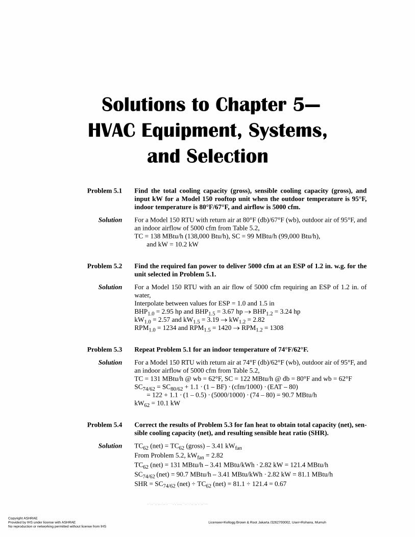
Problem 5.1 Find the total cooling capacity (gross), sensible cooling capacity (gross), andinput kW for a Model 150 rooftop unit when the outdoor temperature is 95°F,indoor temperature is 80°F/67°F, and airflow is 5000 cfm.
Solution For a Model 150 RTU with return air at 80°F (db)/67°F (wb), outdoor air of 95°F, andan indoor airflow of 5000 cfm from Table 5.2,TC = 138 MBtu/h (138,000 Btu/h), SC = 99 MBtu/h (99,000 Btu/h),
and kW = 10.2 kW
Problem 5.2 Find the required fan power to deliver 5000 cfm at an ESP of 1.2 in. w.g. for theunit selected in Problem 5.1.
Solution For a Model 150 RTU with an air flow of 5000 cfm requiring an ESP of 1.2 in. ofwater,Interpolate between values for ESP = 1.0 and 1.5 inBHP1.0 = 2.95 hp and BHP1.5 = 3.67 hp → BHP1.2 = 3.24 hpkW1.0 = 2.57 and kW1.5 = 3.19 → kW1.2 = 2.82 RPM1.0 = 1234 and RPM1.5 = 1420 → RPM1.2 = 1308
Problem 5.3 Repeat Problem 5.1 for an indoor temperature of 74°F/62°F.
Solution For a Model 150 RTU with return air at 74°F (db)/62°F (wb), outdoor air of 95°F, andan indoor airflow of 5000 cfm from Table 5.2,TC = 131 MBtu/h @ wb = 62°F, SC = 122 MBtu/h @ db = 80°F and wb = 62°FSC74/62 = SC80/62 + 1.1 · (1 – BF) · (cfm/1000) · (EAT – 80)
= 122 + 1.1 · (1 – 0.5) · (5000/1000) · (74 – 80) = 90.7 MBtu/hkW62 = 10.1 kW
Problem 5.4 Correct the results of Problem 5.3 for fan heat to obtain total capacity (net), sen-sible cooling capacity (net), and resulting sensible heat ratio (SHR).
Solution TC62 (net) = TC62 (gross) – 3.41 kWfan
From Problem 5.2, kWfan = 2.82TC62 (net) = 131 MBtu/h – 3.41 MBtu/kWh · 2.82 kW = 121.4 MBtu/hSC74/62 (net) = 90.7 MBtu/h – 3.41 MBtu/kWh · 2.82 kW = 81.1 MBtu/hSHR = SC74/62 (net) ÷ TC62 (net) = 81.1 ÷ 121.4 = 0.67
Copyright ASHRAE Provided by IHS under license with ASHRAE Licensee=Kellogg Brown & Root Jakarta /3262700002, User=Rohana, Mumuh
Not for Resale, 09/09/2009 18:54:17 MDTNo reproduction or networking permitted without license from IHS
--`,,``,`,,,`,,`,````,`,`,,,,``,-`-`,,`,,`,`,,`---

HVAC Simplified Solutions Manual
18
Problem 5.5 A building in St. Louis, Missouri, has a sensible heat gain of 23,000 Btu/h and atotal load of 33,000 when outdoor conditions are 97°F/76°F and mixed indoor airconditions entering the cooling coil are 80°F/67°F. Select a cooling unit fromTable 5.3 to meet the load and SHR requirement. Specify the required cfm andresulting EER.
Solution qs = 23,000 Btu/h (23 MBtu/h), q = 33,000 Btu/h (33 MBtu/h)@ to = 97°F/76°F and ti = 80°F/67°F, Q = 1200 cfmSHRLoad = qs ÷ q = 23 MBtu/h / 33 MBtu/h = 0.70For a Model 036, interpolate between values for OAT (aka to) = 95°F and 105°F@ 95°F OAT and EAT (aka ti) 80°F/67°F, TC = 35.8 MBtu/h, SC = 26.4 MBtu/h,
and kW = 2.97@ 105°F OAT and EAT = 80°F/67°F, TC = 34.5 MBtu/h, SC = 25.9 MBtu/h,
and kW = 3.31Via interpolation, TC97 = 35.5 MBtu/h, SC97 = 26.3 MBtu/h, and kW97 = 3.04
Since this manufacturer reports net capacity values, no fan heat deduction is required.
SHRUnit = SC97 ÷ TC97 = 26.3 ÷ 35.3 = 0.74Since SHRUnit ≥ SHRLoad, the unit will not meet the SHR (dehumidification) require-ment at the rated 1200 cfm airflow. Lower cfm to reduce SHR and improve dehumid-ification.
Try lowering flow to 80% of rated flow = 0.80 · 1200 cfm = 960 cfmCFTC = 0.97, TC97/960 = 0.97 · 35.5 = 34.4 CFSC = 0.90, SC97/960 = 0.90 · 26.3 = 23.7, SHRUnit = 23.7 ÷ 34.4 = 0.69 → OKCFkWc = 0.975, kW97/960 = 0.975 · 3.04 = 3.04EER = TC (net) ÷ kW (total) = 34.4 MBtu/h ÷ 3.04 kW = 11.3 MBtu/kWh (Btu/Wh)
Problem 5.6 Repeat Problem 5.5 for an indoor condition of 75°F/63°F.
Solution qs = 23,000 Btu/h (23 MBtu/h), q = 33,000 Btu/h (33 MBtu/h)@ to = 97°F/76°F and ti = 75°F/63°FSHRLoad = qs ÷ q = 23 MBtu/h / 33 MBtu/h = 0.70
For a Model 036, interpolate between values for OAT (aka to) = 95°F and 105°F@ 95°F OAT and EAT (aka ti) 75°F/63°F, TC = 33.4 MBtu/h, SC = 25.7 MBtu/h,
and kW =2.94@ 105°F OAT and EAT = 75°F/63°F, TC = 32.2 MBtu/h, SC = 25.3 MBtu/h,
and kW = 3.28Via interpolation, TC97 = 33.2 MBtu/h, SC97 = 25.6 MBtu/h, and kW97 = 3.01
Since this manufacturer reports net capacity values, no fan heat deduction is required.
SHRUnit = SC97 ÷ TC97 = 25.6 ÷ 33.2 = 0.77 → too high
Reduce airflow and correct performance to see if the unit can meet requirements.Try lowering flow to 80% of rated value = 0.80 · 1200 cfm = 960 cfmCFTC = 0.97, TC97/960 = 0.97 · 33.2 = 32.2 → TC too lowCFSC = 0.90, SC97/1080 = 0.90 · 25.6 = 23.0, SHRUnit = 23.0 ÷ 32.2 = 0.72 → too high
Unit will not meet requirements since increasing flow to meet TC requirement willraise SHR, which is already too high.
Try a larger unit at the lowest possible airflow rate (this may create more problemssince oversized units cycle more frequently and exacerbate humidity problems).
Copyright ASHRAE Provided by IHS under license with ASHRAE Licensee=Kellogg Brown & Root Jakarta /3262700002, User=Rohana, Mumuh
Not for Resale, 09/09/2009 18:54:17 MDTNo reproduction or networking permitted without license from IHS
--`,,``,`,,,`,,`,````,`,`,,,,``,-`-`,,`,,`,`,,`---
Chapter 5—HVAC Equipment, Systems, and Selection
19
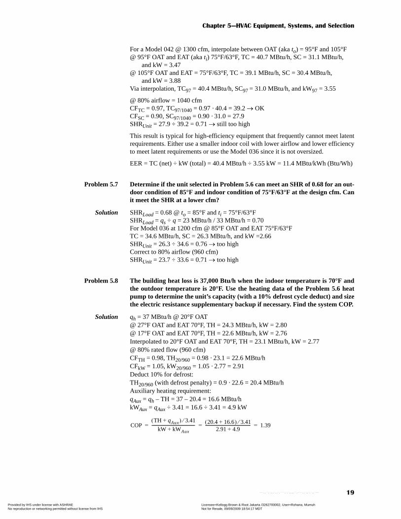
For a Model 042 @ 1300 cfm, interpolate between OAT (aka to) = 95°F and 105°F@ 95°F OAT and EAT (aka ti) 75°F/63°F, TC = 40.7 MBtu/h, SC = 31.1 MBtu/h,
and kW = 3.47@ 105°F OAT and EAT = 75°F/63°F, TC = 39.1 MBtu/h, SC = 30.4 MBtu/h,
and kW = 3.88Via interpolation, TC97 = 40.4 MBtu/h, SC97 = 31.0 MBtu/h, and kW97 = 3.55
@ 80% airflow = 1040 cfmCFTC = 0.97, TC97/1040 = 0.97 · 40.4 = 39.2 → OK CFSC = 0.90, SC97/1040 = 0.90 · 31.0 = 27.9 SHRUnit = 27.9 ÷ 39.2 = 0.71 → still too high
This result is typical for high-efficiency equipment that frequently cannot meet latentrequirements. Either use a smaller indoor coil with lower airflow and lower efficiencyto meet latent requirements or use the Model 036 since it is not oversized.
EER = TC (net) ÷ kW (total) = 40.4 MBtu/h ÷ 3.55 kW = 11.4 MBtu/kWh (Btu/Wh)
Problem 5.7 Determine if the unit selected in Problem 5.6 can meet an SHR of 0.68 for an out-door condition of 85°F and indoor condition of 75°F/63°F at the design cfm. Canit meet the SHR at a lower cfm?
Solution SHRLoad = 0.68 @ to = 85°F and ti = 75°F/63°FSHRLoad = qs ÷ q = 23 MBtu/h / 33 MBtu/h = 0.70For Model 036 at 1200 cfm @ 85°F OAT and EAT 75°F/63°FTC = 34.6 MBtu/h, SC = 26.3 MBtu/h, and kW =2.66 SHRUnit = 26.3 ÷ 34.6 = 0.76 → too highCorrect to 80% airflow (960 cfm)SHRUnit = 23.7 ÷ 33.6 = 0.71 → too high
Problem 5.8 The building heat loss is 37,000 Btu/h when the indoor temperature is 70°F andthe outdoor temperature is 20°F. Use the heating data of the Problem 5.6 heatpump to determine the unit’s capacity (with a 10% defrost cycle deduct) and sizethe electric resistance supplementary backup if necessary. Find the system COP.
Solution qh = 37 MBtu/h @ 20°F OAT@ 27°F OAT and EAT 70°F, TH = 24.3 MBtu/h, kW = 2.80@ 17°F OAT and EAT 70°F, TH = 22.6 MBtu/h, kW = 2.76Interpolated to 20°F OAT and EAT 70°F, TH = 23.1 MBtu/h, kW = 2.77@ 80% rated flow (960 cfm)CFTH = 0.98, TH20/960 = 0.98 · 23.1 = 22.6 MBtu/hCFkW = 1.05, kW20/960 = 1.05 · 2.77 = 2.91Deduct 10% for defrost: TH20/960 (with defrost penalty) = 0.9 · 22.6 = 20.4 MBtu/hAuxiliary heating requirement:qAux = qh – TH = 37 – 20.4 = 16.6 MBtu/hkWAux = qAux ÷ 3.41 = 16.6 ÷ 3.41 = 4.9 kW
COPTH qAux+( ) 3.41⁄
kW kWAux+
--------------------------------------------20.4 16.6+( ) 3.41⁄
2.91 4.9+
---------------------------------------------- 1.39= = =
Copyright ASHRAE Provided by IHS under license with ASHRAE Licensee=Kellogg Brown & Root Jakarta /3262700002, User=Rohana, Mumuh
Not for Resale, 09/09/2009 18:54:17 MDTNo reproduction or networking permitted without license from IHS
--`,,``,`,,,`,,`,````,`,`,,,,``,-`-`,,`,,`,`,,`---
HVAC Simplified Solutions Manual
20
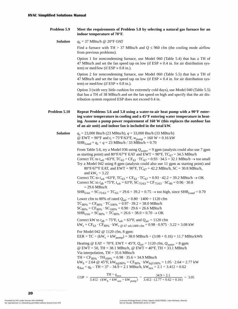
Problem 5.9 Meet the requirements of Problem 5.8 by selecting a natural gas furnace for anindoor temperature of 70°F.
Solution qh = 37 MBtu/h @ 20°F OAT
Find a furnace with TH > 37 MBtu/h and Q ≤ 960 cfm (the cooling mode airflowfrom previous problems).
Option 1 for noncondensing furnace, use Model 060 (Table 5.4) that has a TH of47 MBtu/h and set the fan speed tap on low (if ESP ≈ 0.4 in. for air distribution sys-tem) or med/low (if ESP ≈ 0.8 in.).
Option 2 for noncondensing furnace, use Model 060 (Table 5.5) that has a TH of47 MBtu/h and set the fan speed tap on low (if ESP ≈ 0.4 in. for air distribution sys-tem) or med/low (if ESP ≈ 0.8 in.).
Option 3 (with very little cushion for extremely cold days), use Model 040 (Table 5.5)that has a TH of 38 MBtu/h and set the fan speed on high and specify that the air dis-tribution system required ESP does not exceed 0.4 in.
Problem 5.10 Repeat Problems 5.6 and 5.8 using a water-to-air heat pump with a 90°F enter-ing water temperature in cooling and a 45°F entering water temperature in heat-ing. Assume a pump power requirement of 160 W (this replaces the outdoor fanof an air unit) and indoor fan is included in the total kW.
Solution qs = 23,000 Btu/h (23 MBtu/h), q = 33,000 Btu/h (33 MBtu/h)@ EWT = 90°F and ti = 75°F/63°F, wpump = 160 W = 0.16 kWSHRLoad = qs ÷ q = 23 MBtu/h / 33 MBtu/h = 0.70
From Table 5.6, try a Model 036 using Qwater = 9 gpm (analysis could also use 7 gpmas starting point) and 80°F/67°F EAT and EWT = 90°F, TC67 = 34.5 MBtu/hCorrect TC to twb =63°F, TC63 = CF63 · TC67 = 0.93 · 34.5 = 32.1 MBtu/h → too smallTry a Model 042 using 8 gpm (analysis could also use 11 gpm as starting point) and
80°F/67°F EAT, and EWT = 90°F, TC67 = 42.2 MBtu/h, SC = 30.8 MBtu/h, and kWc = 3.22
Correct TC to twb =63°F, TC63 = CF63 · TC67 = 0.93 · 42.2 = 39.2 MBtu/h → OKCorrect SC to tdb =75°F, twb = 63°F, SC75/63 = CF75/63 · SC80 = 0.96 · 30.8
= 29.6 MBtu/hSHRUnit = SC75/63 ÷ TC63 = 29.6 ÷ 39.2 = 0.75 → too high, since SHRLoad = 0.70
Lower cfm to 80% of rated Qair = 0.80 · 1400 = 1120 cfmTC80% = CF80% · TC100% = 0.97 · 39.2 = 38.0 MBtu/hSC80% = CF80% · SC100% = 0.90 · 29.6 = 26.6 MBtu/hSHRUnit = SC80% ÷ TC80% = 26.6 ÷ 38.0 = 0.70 → OK
Correct kW to tdb = 75°F, twb = 63°F, and Qair = 1120 cfmkWc = CF63 · CF80% · kWc @ 67 wb,1400 cfm = 0.98 · 0.975 · 3.22 = 3.08 kW
For Model 042 @ 1120 cfm, 8 gpm: EER = TC ÷ (kWc + kWpump) = 38.0 MBtu/h ÷ (3.08 + 0.16) = 11.7 MBtu/kWh
Heating @ EAT = 70°F, EWT = 45°F, Qair = 1120 cfm, Qwater = 8 gpm@ EWT = 50, TH = 38.1 MBtu/h, @ EWT = 40°F, TH = 33.1 MBtu/hVia interpolation, TH = 35.6 MBtu/hTH = CF80% · TH100% = 0.98 · 35.6 = 34.9 MBtu/hkWh = 2.64 @ 45°F, kWh@80% = CF80% · kWh@100% = 1.05 · 2.64 = 2.77 kWqAux = qh – TH = 37 – 34.9 = 2.1 MBtu/h, kWaux = 2.1 ÷ 3.412 = 0.62
COPTH qaux+
3.412 kWh kWaux kWpump+ +( )⋅----------------------------------------------------------------------------------
34.9 2.1+
3.412 2.77 0.62 0.16+ +( )⋅------------------------------------------------------------------- 3.05= = =
Copyright ASHRAE Provided by IHS under license with ASHRAE Licensee=Kellogg Brown & Root Jakarta /3262700002, User=Rohana, Mumuh
Not for Resale, 09/09/2009 18:54:17 MDTNo reproduction or networking permitted without license from IHS
--`,,``,`,,,`,,`,````,`,`,,,,``,-`-`,,`,,`,`,,`---
Chapter 5—HVAC Equipment, Systems, and Selection
21
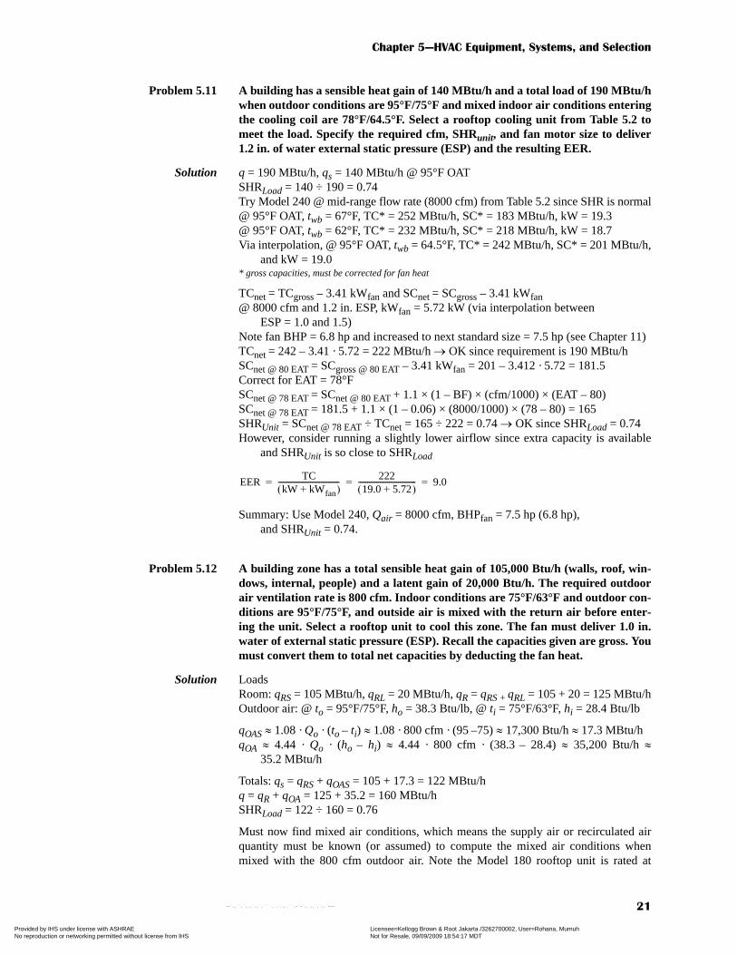
Problem 5.11 A building has a sensible heat gain of 140 MBtu/h and a total load of 190 MBtu/hwhen outdoor conditions are 95°F/75°F and mixed indoor air conditions enteringthe cooling coil are 78°F/64.5°F. Select a rooftop cooling unit from Table 5.2 tomeet the load. Specify the required cfm, SHRunit, and fan motor size to deliver1.2 in. of water external static pressure (ESP) and the resulting EER.
Solution q = 190 MBtu/h, qs = 140 MBtu/h @ 95°F OAT SHRLoad = 140 ÷ 190 = 0.74Try Model 240 @ mid-range flow rate (8000 cfm) from Table 5.2 since SHR is normal@ 95°F OAT, twb = 67°F, TC* = 252 MBtu/h, SC* = 183 MBtu/h, kW = 19.3@ 95°F OAT, twb = 62°F, TC* = 232 MBtu/h, SC* = 218 MBtu/h, kW = 18.7Via interpolation, @ 95°F OAT, twb = 64.5°F, TC* = 242 MBtu/h, SC* = 201 MBtu/h,
and kW = 19.0* gross capacities, must be corrected for fan heat
TCnet = TCgross – 3.41 kWfan and SCnet = SCgross – 3.41 kWfan@ 8000 cfm and 1.2 in. ESP, kWfan = 5.72 kW (via interpolation between
ESP = 1.0 and 1.5)Note fan BHP = 6.8 hp and increased to next standard size = 7.5 hp (see Chapter 11)TCnet = 242 – 3.41 · 5.72 = 222 MBtu/h → OK since requirement is 190 MBtu/hSCnet @ 80 EAT = SCgross @ 80 EAT – 3.41 kWfan = 201 – 3.412 · 5.72 = 181.5Correct for EAT = 78°FSCnet @ 78 EAT = SCnet @ 80 EAT + 1.1 × (1 – BF) × (cfm/1000) × (EAT – 80)SCnet @ 78 EAT = 181.5 + 1.1 × (1 – 0.06) × (8000/1000) × (78 – 80) = 165SHRUnit = SCnet @ 78 EAT ÷ TCnet = 165 ÷ 222 = 0.74 → OK since SHRLoad = 0.74However, consider running a slightly lower airflow since extra capacity is available
and SHRUnit is so close to SHRLoad
Summary: Use Model 240, Qair = 8000 cfm, BHPfan = 7.5 hp (6.8 hp), and SHRUnit = 0.74.
Problem 5.12 A building zone has a total sensible heat gain of 105,000 Btu/h (walls, roof, win-dows, internal, people) and a latent gain of 20,000 Btu/h. The required outdoorair ventilation rate is 800 cfm. Indoor conditions are 75°F/63°F and outdoor con-ditions are 95°F/75°F, and outside air is mixed with the return air before enter-ing the unit. Select a rooftop unit to cool this zone. The fan must deliver 1.0 in.water of external static pressure (ESP). Recall the capacities given are gross. Youmust convert them to total net capacities by deducting the fan heat.
Solution LoadsRoom: qRS = 105 MBtu/h, qRL = 20 MBtu/h, qR = qRS + qRL = 105 + 20 = 125 MBtu/hOutdoor air: @ to = 95°F/75°F, ho = 38.3 Btu/lb, @ ti = 75°F/63°F, hi = 28.4 Btu/lb
qOAS ≈ 1.08 · Qo · (to – ti) ≈ 1.08 · 800 cfm · (95 –75) ≈ 17,300 Btu/h ≈ 17.3 MBtu/hqOA ≈ 4.44 · Qo · (ho – hi) ≈ 4.44 · 800 cfm · (38.3 – 28.4) ≈ 35,200 Btu/h ≈
35.2 MBtu/h
Totals: qs = qRS + qOAS = 105 + 17.3 = 122 MBtu/hq = qR + qOA = 125 + 35.2 = 160 MBtu/hSHRLoad = 122 ÷ 160 = 0.76
Must now find mixed air conditions, which means the supply air or recirculated airquantity must be known (or assumed) to compute the mixed air conditions whenmixed with the 800 cfm outdoor air. Note the Model 180 rooftop unit is rated at
EERTC
kW kWfan+( )----------------------------------
22219.0 5.72+( )-------------------------------- 9.0= = =
Copyright ASHRAE Provided by IHS under license with ASHRAE Licensee=Kellogg Brown & Root Jakarta /3262700002, User=Rohana, Mumuh
Not for Resale, 09/09/2009 18:54:17 MDTNo reproduction or networking permitted without license from IHS
--`,,``,`,,,`,,`,````,`,`,,,,``,-`-`,,`,,`,`,,`---

HVAC Simplified Solutions Manual
22
6000 cfm for the mid-range value. Since the SHRLoad is also a mid-range value, usethis flow rate for first computation; 5200 cfm of recirculated air at is mixed with800 cfm of outside air 95°F/75°F to provide 6000 cfm of supply air.
Using PsychProcess.xls (mixing) provides a mixed air condition ≈ 78°F/65°F enteringthe rooftop unit.
Via interpolation, @ 95°F OAT, twb = 65°F for a Model 180 rooftop unitTC = 184 MBtu/h, SC = 147 MBtu/h, kW = 14.0 (gross capacities)To correct for fan heat, go to fan data at 6000 cfm and 1.0 in. ESP:kWfan = 3.32, BHP = 3.89 hp (need 5 hp motor)
TCnet = TCgross – 3.41 kWfan and SCnet = SCgross – 3.41 kWfan
TCnet = 184 – 3.41 · 3.32 = 173 MBtu/h → OK since requirement is 160 MBtu/hSCnet @ 80 EAT = SCgross @ 80 EAT – 3.41 kWfan = 147 – 3.412 · 3.32 = 136Correct for EAT = 78°FSCnet @ 78 EAT = SCnet @ 80 EAT + 1.1 · (1 – BF) · (cfm/1000) · (EAT – 80)SCnet @ 78 EAT = 136 + 1.1 · (1 – 0.04) · (6000/1000) · (78 – 80) = 123SHRUnit = SCnet @ 78 EAT ÷ TCnet = 123 ÷ 173 = 0.71 → Excellent, since
SHRLoad = 0.76 (flow can be increased since SHRUnit is lower, but this is notnecessary since unit is slightly oversized).
Model 180 operating at 6000 cfm with 5 hp fan motor is suitable.
Problem 5.13 A water-cooled chiller must provide water at 45°F to ten fan coil units thatrequire 45 MBtu/h (net) each with fans that draw 600 W each. The condenserwater is cooled with a cooling tower that can provide 85°F.
a. Select a chiller to meet this load.b. Calculate the required chilled water flow in gpm for a 55°F chiller enter-
ing temperature (base answer on chiller capacity).c. Calculate the required condenser water flow based on 3.0 gpm per ton of
chiller capacity.d. Determine the head loss in feet of water across the evaporator and con-
denser.e. Determine the chiller gross kW/ton (gross) and EER (Btu/W·h).f. Determine system net kW/ton and EER if two pumps (chilled water and
condenser water) draw 2.0 kW and 2.25 kW, respectively.
Solution qLoad = 10 FCUs · (45,000 Btu/h + 3.41 · 600 W) = 470,500 Btu/h = 39.2 tonsa. A Model 040 (Table 5.10 ) water-cooled scroll compressor chiller will deliver:
Qair1 5200 cfm Qair2 800 cfm
QSair1 5064 scfm QSair2 740 scfm
Stream 1 Stream 2
mflow1 22789 lb/hr mflow2 3332 lb/hr
Stream 3 (mixed)
mflow3 26120 lb/hr
Qair3 6000 cfm
Tdb3 78.2 °F
HRatio3 0.0100 lbw/lba
69.8 Grains
Twb3 64.8 °F
RelHum3 48.7 %
SpHt3 0.244 Btu/lb-°F
Enal3 29.7 Btu/lb
SpVol3 13.78 cu.ft./lb
DewPt3 57.2 °F
Note: Input values (Qair1 and Qair2) are in cubic feet per minute.
For additional information purposes, these values are corrected to air
at standard conditions of ρ=0.075 lb/cu.ft. (QSair1 and QSair2).
Stream 2 @
Qair2(cfm),
Tdb2(°F),
& Twb2(°F)
Stream 1 @
Qair1(cfm),
Tdb1(°F),
& Twb1(°F)
Stream 3 @
Qair3(cfm),
Tdb3(°F),
& Twb3(°F)
1
2
3
EERTC
kW kWfan+( )----------------------------------
17314.0 3.32+( )-------------------------------- 10.0= = =
Copyright ASHRAE Provided by IHS under license with ASHRAE Licensee=Kellogg Brown & Root Jakarta /3262700002, User=Rohana, Mumuh
Not for Resale, 09/09/2009 18:54:17 MDTNo reproduction or networking permitted without license from IHS
--`,,``,`,,,`,,`,````,`,`,,,,``,-`-`,,`,,`,`,,`---

Chapter 5—HVAC Equipment, Systems, and Selection
23
TC = 40.1 tons = 40.1 · 12,000 Btu/ton-h = 481,200 Btu/h@ 45°F LWT and 85°F Condenser EWTCompressor demand will be 30.4 kW (30,400 W)
b. gpm(Evap.) = 481,200 Btu/h ÷ [500 · (55°F – 45°F)] = 96 gpmc. gpm(Cond.) = 3 gpm/ton · 40.1 tons = 120 gpmd. From Figure 5.13 for 040 Chiller @ 96 gpm: hEvap = 13 ft of water
From Figure 5.14 for 040 Chiller @ 120 gpm: hCond = 15.3 ft of watere. kW/ton (gross) = 30.4 kW ÷ 40.1 tons = 0.76 kW/ton
EER (gross) = 481,200 Btu/h ÷ 30,400 W = 15.8 Btu/Whf.
Problem 5.14. A four-zone building has the loads shown below. The room air entering the coilsis 80°F/67°F and chilled water at 45°F is supplied. Select fan coil units (assuminga 10% deduction for fan heat) and specify airflow and water flow while attempt-ing to maintain a coil outlet temperature of 55°F ±2.0°F.
Solution Increase loads given in table by 10% to account for fan heat (this will be added to boththe sensible and totals loads).
Zone 1:Peak load occurs at 3 p.m.: q1-Load = 66 MBtu/h and SHR1-Load = 48 ÷ 66 = 0.73A model 60-HW-4 coil at 2000 cfm, 80°F/67°F air and 13 gpm:
TC = 65 MBtu/h (Too low)at 21 gpm: TC = 75.2 MBtu/h (High)Reduce flow to 17 gpm and by interpolation: TC = 70.1 MBtu/h, SC = 46.7 MBtu/hCheck SHRFCU = 46.7 ÷ 70.1 = 0.67 (OK)Check outlet water temperature:
Flow of 17 gpm is acceptable, but try a lower flow.Reduce flow to 15 gpm and by interpolation: TC = 67.6 MBtu/h, SC = 45.8 MBtu/hCheck SHRFCU = 45.8 ÷ 67.6 = 0.68 (OK)
EERNet
qGross qFan–
WChiller WFcuFans WCWPump WCHWPump+ + +
---------------------------------------------------------------------------------------------------------------------=
481 200 Btu/h, 10 3.412 600 W⋅( )⋅–
30 400 W, 10 600 W⋅ 2250 W 2000 W+ + +
--------------------------------------------------------------------------------------------------------------=
11.3 Btu/Wh=
10 a.m. Cooling Loads (MBtu/h) 3 p.m. Cooling Loads (MBtu/h)
Sensible Total Sensible Total
Zone 1 30 40 42 60
Zone 2 45 60 35 45
Zone 3 25 35 38 54
Zone 4 30 38 40 55
Total
10 a.m. 3 p.m.
Sensible Total Sensible Total
Zone 1 34 44 48 66
Zone 2 51 66 39.5 49.5
Zone 3 28.5 38.5 43.4 59.4
Zone 4 33.8 41.8 45.5 60.5
Totals 147.3 190.3 176.4 235.4
to ti °F( )TC Btu/h( )
500 Q gpm( )×-----------------------------------+ 45°F
70 100 Btu/h,500 17 gpm×---------------------------------+ 53.2°F= = =
Copyright ASHRAE Provided by IHS under license with ASHRAE Licensee=Kellogg Brown & Root Jakarta /3262700002, User=Rohana, Mumuh
Not for Resale, 09/09/2009 18:54:17 MDTNo reproduction or networking permitted without license from IHS
--`,,``,`,,,`,,`,````,`,`,,,,``,-`-`,,`,,`,`,,`---

HVAC Simplified Solutions Manual
24
Check outlet water temperature:
Zone 2:Use same coil and water flow as zone 1 to meet 10 a.m. load, which is also 66 MBtu/h
with slightly higher SHR. So Model 60-HW-4 coil at 2000 cfm and 15 gpm willwork.
Zone 3:Use same coil as zones 1 and 2, but water flow can be lowered to 13 gpm:TC = 65 MBtu/h, SC = 44.9, SHRLoad = 43.4 ÷ 59.4 = 0.73;
SHRFCU = 44.9 ÷ 65.0 = 0.69 (OK) Check outlet water temperature:
So Model 60-HW-4 coil at 2000 cfm and 13 gpm will work.
Zone 4:Use same coil and water flow as zone 3 to meet 3 p.m. load, which is 60.5 MBtu/h. TC = 65 MBtu/h, SC = 44.9, SHRLoad = 45.5 ÷ 60.5 = 0.75;
SHRFCU = 44.9 ÷ 65.0 = 0.69 (OK) So Model 60-HW-4 coil at 2000 cfm and 13 gpm will work.
Problem 5.15 Select a chiller (or chillers) to meet the combined loads of the coils inProblem 5.14. Specify unit model number, required water flow, and gross kW/ton and EER.
Solution The peak block load occurs at 3 p.m. (although load in zone 2 peaks at 10 a.m.).At 3 p.m., qLoads = 235.4 MBtu/h = 19.6 tonsA Model 020 (Table 5.10) water-cooled scroll compressor chiller will deliver:
TC = 20.4 tons = 20.4 · 12,000 Btu/ton-h = 244,800 Btu/h @ 45°F LWT and 85°F Cond. EWT
Compressor demand will be 15.4 kW (15,400 W).
gpm(Evap.) = 244,800 Btu/h ÷ [500 · (55°F – 45°F)] = 49 gpm
kW/ton (gross) = 15.4 kW ÷ 20.4 tons = 0.75 kW/tonEER (gross) = 244,800 Btu/h ÷ 15,400 W = 15.9 Btu/Wh
to ti °F( )TC Btu/h( )
500 Q gpm( )×-----------------------------------+ 45°F
67 600 Btu/h,500 15 gpm×---------------------------------+ 54.0°F= = =
to ti °F( )TC Btu/h( )
500 Q gpm( )×-----------------------------------+ 45°F
65 000 Btu/h,500 13 gpm×---------------------------------+ 55.0°F= = =
Copyright ASHRAE Provided by IHS under license with ASHRAE Licensee=Kellogg Brown & Root Jakarta /3262700002, User=Rohana, Mumuh
Not for Resale, 09/09/2009 18:54:17 MDTNo reproduction or networking permitted without license from IHS
--`,,``,`,,,`,,`,````,`,`,,,,``,-`-`,,`,,`,`,,`---

Solutions to Chapter 6—
Comfort, Air Quality,
and Climatic Data
Problem 6.1 Compute the heat rate of a 5 ft, 10 in., 160 lb male machinist at work.
Solution AD = 0.108 · m0.425 · l 0.725 = 0.108 · 160 lb.0.425 · 70 in.0.725 = 20.3 ft2
Doing light machine work generates 37 to 44 Btu/h·ft2 (mid-range = 40.5 Btu/h·ft2)Thus, Qmachinist = 40.5 Btu/h·ft2 · 20.3 ft2 = 820 Btu/h
Problem 6.2 Repeat Problem 6.1 for a 5 ft, 6 in., 120 lb performing ballerina.
Solution AD = 0.108 · m0.425 · l 0.725 = 0.108 · 120 lb.0.425 · 66 in.0.725 = 19.1 ft2
A ballerina generates 44 to 81 Btu/h·ft2 (mid-range = 62.5 Btu/h·ft2)Thus, qballerina = 62.5 Btu/h·ft2 · 19.1 ft2 = 1190 Btu/h
Problem 6.3 What range of indoor temperature and humidity is best to satisfy occupants inthe summer? In the winter? Why is there a difference?
Solution At the upper relative humidity level of 60%, the indoor temperature should be in the73°F to 79ºF range to satisfy the most individuals in the summer. At the lower relativehumidity level of 30%, the indoor temperature should be in the 74°F to 81°F range tosatisfy the most individuals in the summer.
At the upper relative humidity level of 60%, the indoor temperature should be in the68°F to 74ºF range to satisfy the most individuals in the winter (this condition is diffi-cult to maintain in the winter because the outside air is drier). At the lower relativehumidity level of 30%, the indoor temperature should be in the 69°F to 76°F range tosatisfy the most individuals in the winter.
The temperatures are lower in the winter because occupants are typically dressed withheavier clothing in the winter because of the lower outdoor temperature.
Problem 6.4 Why are people more comfortable in the winter with a lower thermostat setting?
Solution Occupants are comfortable with a lower setting in the winter because they are typi-cally dressed with heavier clothing because of the lower outdoor temperature.
Copyright ASHRAE Provided by IHS under license with ASHRAE Licensee=Kellogg Brown & Root Jakarta /3262700002, User=Rohana, Mumuh
Not for Resale, 09/09/2009 18:54:17 MDTNo reproduction or networking permitted without license from IHS
--`,,``,`,,,`,,`,````,`,`,,,,``,-`-`,,`,,`,`,,`---
HVAC Simplified Solutions Manual
26
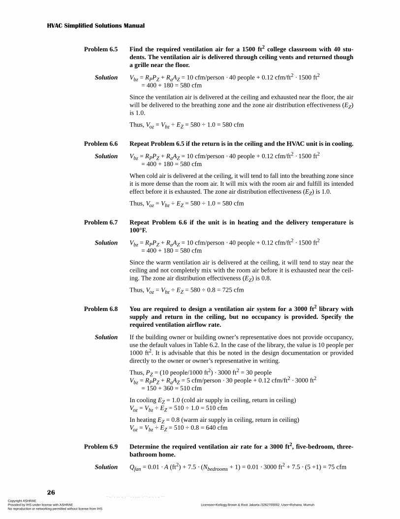
Problem 6.5 Find the required ventilation air for a 1500 ft2 college classroom with 40 stu-dents. The ventilation air is delivered through ceiling vents and returned thougha grille near the floor.
Solution Vbz = RPPZ + RaAZ = 10 cfm/person · 40 people + 0.12 cfm/ft2 · 1500 ft2
= 400 + 180 = 580 cfm
Since the ventilation air is delivered at the ceiling and exhausted near the floor, the airwill be delivered to the breathing zone and the zone air distribution effectiveness (EZ)is 1.0.
Thus, Voz = Vbz ÷ EZ = 580 ÷ 1.0 = 580 cfm
Problem 6.6 Repeat Problem 6.5 if the return is in the ceiling and the HVAC unit is in cooling.
Solution Vbz = RPPZ + RaAZ = 10 cfm/person · 40 people + 0.12 cfm/ft2 · 1500 ft2
= 400 + 180 = 580 cfm
When cold air is delivered at the ceiling, it will tend to fall into the breathing zone sinceit is more dense than the room air. It will mix with the room air and fulfill its intendedeffect before it is exhausted. The zone air distribution effectiveness (EZ) is 1.0.
Thus, Voz = Vbz ÷ EZ = 580 ÷ 1.0 = 580 cfm
Problem 6.7 Repeat Problem 6.6 if the unit is in heating and the delivery temperature is100°F.
Solution Vbz = RPPZ + RaAZ = 10 cfm/person · 40 people + 0.12 cfm/ft2 · 1500 ft2
= 400 + 180 = 580 cfm
Since the warm ventilation air is delivered at the ceiling, it will tend to stay near theceiling and not completely mix with the room air before it is exhausted near the ceil-ing. The zone air distribution effectiveness (EZ) is 0.8.
Thus, Voz = Vbz ÷ EZ = 580 ÷ 0.8 = 725 cfm
Problem 6.8 You are required to design a ventilation air system for a 3000 ft2 library withsupply and return in the ceiling, but no occupancy is provided. Specify therequired ventilation airflow rate.
Solution If the building owner or building owner’s representative does not provide occupancy,use the default values in Table 6.2. In the case of the library, the value is 10 people per1000 ft2. It is advisable that this be noted in the design documentation or provideddirectly to the owner or owner’s representative in writing.
Thus, PZ = (10 people/1000 ft2) · 3000 ft2 = 30 peopleVbz = RPPZ + RaAZ = 5 cfm/person · 30 people + 0.12 cfm/ft2 · 3000 ft2
= 150 + 360 = 510 cfm
In cooling EZ = 1.0 (cold air supply in ceiling, return in ceiling)Voz = Vbz ÷ EZ = 510 ÷ 1.0 = 510 cfm
In heating EZ = 0.8 (warm air supply in ceiling, return in ceiling)Voz = Vbz ÷ EZ = 510 ÷ 0.8 = 640 cfm
Problem 6.9 Determine the required ventilation air rate for a 3000 ft2, five-bedroom, three-bathroom home.
Solution Qfan = 0.01 · A (ft2) + 7.5 · (Nbedrooms + 1) = 0.01 · 3000 ft2 + 7.5 · (5 +1) = 75 cfm
Copyright ASHRAE Provided by IHS under license with ASHRAE Licensee=Kellogg Brown & Root Jakarta /3262700002, User=Rohana, Mumuh
Not for Resale, 09/09/2009 18:54:17 MDTNo reproduction or networking permitted without license from IHS
--`,,``,`,,,`,,`,````,`,`,,,,``,-`-`,,`,,`,`,,`---

Chapter 6—Comfort, Air Quality, and Climatic Data
27
Problem 6.10 A building with four zones has the airflow requirements below. Determine therequired ventilation air rate for a multi-zone ventilation air system.
Supply air: Zone 1 = 800 cfm, Zone 2 = 1200 cfm,Zone 3 = 700 cfm, Zone 4 = 1500 cfm
Ventilation air: Zone 1 = 200 cfm, Zone 2 = 275 cfm, Zone 3 = 150 cfm, Zone 4 = 500 cfm
Solution
Assume EZ = 1.0, Vou = ΣVbz ÷ EZ = (200 + 275 + 150 + 500) ÷ 1.0 = 1125 cfmEv = 0.8 since Zp (max) ≤ 0.35Vot = Vou ÷ EV = 1125 ÷ 0.8 = 1406 cfm
Problem 6.11 An office with six zones is served with a single rooftop unit that provides 1.0 cfm/ft2
of supply air through the ceiling. The return is also in the ceiling. Ventilation air issupplied at the rooftop unit return. Compute the required ventilation air rate inthe summer and winter given the following table.
Solution For summer [EZ = 1.0 (cold air supply in ceiling, return in ceiling)] and assuming thatoccupants move from their office to occupy the conference room so that the normalnumber of people in the building is 20 (not 30).
For winter, EZ = 0.8 (warm air supply in ceiling, return in ceiling)
Zone Vz Vp Zp (Vz/Vp)
1 200 800 0.25
2 275 1200 0.23
3 150 700 0.21
4 500 1500 0.33 ←Zpmax
Zone Use People Area (ft2)1 Reception 5 7002 Office 2 4003 Office 8 8004 Office 4 7005 Conference 10 5006 Office 1 400
Multi-Zone Systems Only
Zone Description Zone Number Rp No. of People Rp*people Ra A (ft2) Ra*Area Vbz Vp Vp Zp
Reception 1 5 5 25 0.06 200 12 37 200 0.19
Office 2 5 2 10 0.06 300 18 28 300 0.09
Office 3 5 8 40 0.06 300 18 58 300 0.19
Office 4 5 4 20 0.06 400 24 44 400 0.11
Conference 5 5 10 50 0.06 250 15 65 250 0.26
Office 6 5 1 5 0.06 300 18 23 300 0.08
7 0 0 0 0 0.00
8 0 0.00
9 0 0.00
10 0 0.00
Totals 30 150 1750 105 Zpmax 0.26
Max Building occupants 20 people
Diversity 0.67
Ez 1.00
Vou 205 cfm
Estimated Vp/A 1.00 cfm/ft2
Ev 0.8
Vo 256 cfm
Multi-Zone Systems Only
Zone Description Zone Number Rp No. of People Rp*people Ra A (ft2) Ra*Area Vbz Vp Vp Zp
Reception 1 5 5 25 0.06 200 12 37 200 0.19
Office 2 5 2 10 0.06 300 18 28 300 0.09
Office 3 5 8 40 0.06 300 18 58 300 0.19
Office 4 5 4 20 0.06 400 24 44 400 0.11
Conference 5 5 10 50 0.06 250 15 65 250 0.26
Office 6 5 1 5 0.06 300 18 23 300 0.08
7 0 0 0 0 0.00
8 0 0.00
9 0 0.00
10 0 0.00
Totals 30 150 1750 105 Zpmax 0.26
Max Building occupants 20 people
Diversity 0.67
Ez 0.80
Vou 256 cfm
Estimated Vp/A 1.00 cfm/ft2
Ev 0.8
Vo 320 cfm
Copyright ASHRAE Provided by IHS under license with ASHRAE Licensee=Kellogg Brown & Root Jakarta /3262700002, User=Rohana, Mumuh
Not for Resale, 09/09/2009 18:54:17 MDTNo reproduction or networking permitted without license from IHS
--`,,``,`,,,`,,`,````,`,`,,,,``,-`-`,,`,,`,`,,`---
HVAC Simplified Solutions Manual
28
Problem 6.12 Find the following for Chicago:ElevationDry-bulb temperature at 0.4% cooling designMean wet-bulb temperature at 0.4% cooling designTemperature at 99.6% heating design condition 0.4% design wet-bulbDry-bulb temperature at 0.4% WB conditionDaily range on cooling design day
Solution For Chicago from Table 6.5:Elevation = 673 ft above sea leveltdb @ 0.4% = 91°FtMWB @ 0.4% tdb = 74°Ftdb @ 99.6% = –6°Ftwb @ 0.4% = 77°FtMDB @ 0.4% twb = 88°FDR = 20°F
Problem 6.13 Repeat Problem 6.12 for Tuscaloosa, Alabama.
Solution For Tuscaloosa from Table 6.5:Elevation = 171 ft above sea leveltdb @ 0.4% = 95°FtMWB @ 0.4% tdb = 77°Ftdb @ 99.6% = 20°Ftwb @ 0.4% = 80°FtMDB @ 0.4% twb = 90°FDR = 20°F
Problem 6.14 Explain the meaning of 99.6% and 0.4% design conditions in Table 6.3.
Solution This notation means that the value of the temperature in the table is exceeded during99.6% of the hours during a normal year. Likewise, the 0.4% temperature is exceededduring only 0.4% of the hours during a normal year.
Copyright ASHRAE Provided by IHS under license with ASHRAE Licensee=Kellogg Brown & Root Jakarta /3262700002, User=Rohana, Mumuh
Not for Resale, 09/09/2009 18:54:17 MDTNo reproduction or networking permitted without license from IHS
--`,,``,`,,,`,,`,````,`,`,,,,``,-`-`,,`,,`,`,,`---

Solutions to Chapter 7—
Heat and Moisture Flow in Buildings
Problem 7.1 Find the overall U-factor and R-value for a 2 × 4 in. wall with R-13 fiberglassbatts (approximately 20% of the wall is framing). The exterior wall is 5/8 in.hardboard (standard tempered) over 1/2 in. vegetable fiberboard with no airgap. The interior finish is 1/2 in. gypsum board.
Solution
Problem 7.2 Repeat Problem 7.1 if the exterior finish is 110 lb/ft3 4 in. face brick.
Solution
Problem 7.3 Find the overall U-factors (Btu/h⋅°F⋅ft2) and R-values (h⋅°F⋅ft2/Btu) of a 2.25 in.thick solid wood door with and without a metal storm door.
Solution From Table 7.1 for 2.25 in. solid wood doorU = 0.27 Btu/h·°F·ft2, R = 3.7 h·°F·ft2/Btu
With storm doorU = 0.20 Btu/h·°F·ft2, R = 5.0 h·°F·ft2/Btu
Problem 7.4 Find the overall U-factor (Btu/h⋅°F⋅ft2) and R-value (h⋅°F⋅ft2/Btu) of the wall inthe building shown below.
Solution Assuming the 1 in. insulation is expanded polystyrene (aka beadboard):
Assuming the 1 in. insulation is extruded polystyrene (aka pink or blue board):
% Total Area Out. Surface Out. Finish Insulation Wood Sheath Other Int. Finish In. Surface R-Path Total
R-Insul. Path = 80 0.25 0.85 13 1.32 0.45 0.68 16.55
R-Wood Path = 20 0.25 0.85 4.375 1.32 0.45 0.68 7.925
U (Overall)= 0.074 Btu/hr-ft2-F
R(Total)= 13.59 hr-ft2-F/Btu
=0.20*7.925+0.8*16.55
=1/0.074
% Total Area Out. Surface Out. Finish Insulation Wood Sheath Other Int. Finish In. Surface R-Path Total
R-Insul. Path = 80 0.25 0.45 13 1.32 0.45 0.68 16.15
R-Wood Path = 20 0.25 0.45 4.375 1.32 0.45 0.68 7.525
U (Overall)= 0.076 Btu/hr-ft2-F
R(Total)= 13.14 hr-ft2-F/Btu
=0.20*7.525+0.8*16.15
=1/0.076
Out. Surface FaceBrick Insulation Other Other 8"LW block In. Surf.
R(Total)= 0.25 0.45 3.5 2.4 0.68 7.28
R(Total)= 7.28 hr-ft2-F/Btu
U (Overall)= 0.137 Btu/hr-ft2-F
=1/7.28
Out. Surface FaceBrick Insulation Other Other 8"LW block In. Surf.
R(Total)= 0.25 0.45 5 2.4 0.68 8.78
R(Total)= 8.78 hr-ft2-F/Btu
U (Overall)= 0.114 Btu/hr-ft2-F
=1/8.78
Copyright ASHRAE Provided by IHS under license with ASHRAE Licensee=Kellogg Brown & Root Jakarta /3262700002, User=Rohana, Mumuh
Not for Resale, 09/09/2009 18:54:17 MDTNo reproduction or networking permitted without license from IHS
--`,,``,`,,,`,,`,````,`,`,,,,``,-`-`,,`,,`,`,,`---
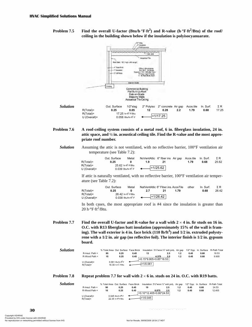
HVAC Simplified Solutions Manual
30
Problem 7.5 Find the overall U-factor (Btu/h⋅°F⋅ft2) and R-value (h⋅°F⋅ft2/Btu) of the roof/ceiling in the building shown below if the insulation is polyisocyanuarate.
Solution
Problem 7.6 A roof-ceiling system consists of a metal roof, 6 in. fiberglass insulation, 24 in.attic space, and ½ in. acoustical ceiling tile. Find the R-value and the most appro-priate roof number.
Solution Assuming the attic is not ventilated, with no reflective barrier, 100°F ventilation airtemperature (see Table 7.2):
If attic is naturally ventilated, with no reflective barrier, 100°F ventilation air temper-ature (see Table 7.2):
In both cases, the most appropriate roof is #4 since the insulation is greater than20 h·°F·ft2/Btu.
Problem 7.7 Find the overall U-factor and R-value for a wall with 2 × 4 in. fir studs on 16 in.O.C. with R13 fiberglass batt insulation (approximately 15% of the wall is fram-ing). The wall exterior is 4 in. face brick (110 lb/ft3) and 1/2 in. extruded polysty-rene with a 1/2 in. air gap (no reflective foil). The interior finish is 1/2 in. gypsumboard.
Solution
Problem 7.8 Repeat problem 7.7 for wall with 2 × 6 in. studs on 24 in. O.C. with R19 batts.
Solution
Out. Surface 1/2"slag 2" Polyiso 2" concrete Air gap Acos.tile In. Surf. Σ R
R(Total)= 0.25 0.05 12 0.28 2.2 1.79 0.68 17.25
R(Total)= 17.25 hr-ft2-F/Btu
U (Overall)= 0.058 Btu/hr-ft2-F =1/17.25
Out. Surface Metal NoVentAttic 6" fiber ins Air gap Acos.tile In. Surf. Σ R
R(Total)= 0.25 0 1.9 21 1.79 0.68 25.62
R(Total)= 25.62 hr-ft2-F/Btu
U (Overall)= 0.039 Btu/hr-ft2-F =1/25.62
Out. Surface Metal NatVentAttic 6" Fiber.ins.AcosTile other In. Surf. Σ R
R(Total)= 0.25 0 2.7 21 1.79 0.68 26.42
R(Total)= 26.42 hr-ft2-F/Btu
U (Overall)= 0.038 Btu/hr-ft2-F
=1/26.42
% Total Area Out. Surface Face Brick Insulation 3½"wood½" extr,poly Air gap 1/2" Gyp. In. Surface R-Path Total
R-Insul. Path = 85 0.25 0.45 13 2.5 1.2 0.45 0.68 18.53
R-Wood Path = 15 0.25 0.45 4.375 2.5 1.2 0.45 0.68 9.905
U (Overall)= 0.061 Btu/hr-ft2-F
R(Total)= 16.39 hr-ft2-F/Btu
=0.15*9.905+0.85*18.53
=1/0.061
% Total Area Out. Surface Face Brick Insulation 5½"wood½" extr,poly Air gap 1/2" Gyp. In. Surface R-Path Total
R-Insul. Path = 90 0.25 0.45 19 2.5 1.2 0.45 0.68 24.53
R-Wood Path = 10 0.25 0.45 6.875 2.5 1.2 0.45 0.68 12.405
U (Overall)= 0.045 Btu/hr-ft2-F
R(Total)= 22.35 hr-ft2-F/Btu
=0.10*12.405+0.80*24.53
=1/0.045
Copyright ASHRAE Provided by IHS under license with ASHRAE Licensee=Kellogg Brown & Root Jakarta /3262700002, User=Rohana, Mumuh
Not for Resale, 09/09/2009 18:54:17 MDTNo reproduction or networking permitted without license from IHS
--`,,``,`,,,`,,`,````,`,`,,,,``,-`-`,,`,,`,`,,`---

Chapter 7—Heat and Moisture Flow in Buildings
31
Problem 7.9 Find the overall U-factors (Btu/h⋅°F⋅ft2) and R-values (h⋅°F⋅ft2/Btu) of 1.75 in.thick steel door with a urethane core (no thermal break) with and without ametal storm door.
Solution From Table 7.1 for 1.75 in. steel door with a urethane core and no thermal break:U = 0.40 Btu/h·°F·ft2, R = 2.5 h·°F·ft2/Btu
With storm door:U = 0.26 Btu/h·°F·ft2, R = 3.8 h·°F·ft2/Btu
Problem 7.10 Find the overall U-factor (Btu/h⋅°F⋅ft2) and R-value (h⋅°F⋅ft2/Btu) of a vinylframe, double-glass window with a ½ in. air gap and no thermal break.
Solution From Table 7.3 (assuming resistance of a ½ in. air gap ≈ resistance of a ¼ in. air gap):U = 0.55 Btu/h·°F·ft2, R = 1/U = 1.82 h·°F·ft2/Btu
Problem 7.11 Find the R-value of a wall that is 4 in. face brick, 2 in. insulation, and 8 in. heavy-weight concrete walls. What wall number most closely matches this wall?
Solution
Wall #16
Problem 7.12 Find the overall U-factor (Btu/h⋅°F⋅ft2) and R-value (h⋅°F⋅ft2/Btu) of an alumi-num frame, double-glass window with a ½ in. air gap and no thermal break.
Solution From Table 7.3 (assuming resistance of a ½ in. air gap ≈ resistance of a ¼ in. air gap):U = 0.87 Btu/h·°F·ft2, R = 1/U = 1.15 h·°F·ft2/Btu
Problem 7.13 Find the overall U-factor (Btu/h⋅°F⋅ft2) and R-value (h⋅°F⋅ft2/Btu) of a 1.75 in.thick wood door with and without a metal storm door.
Solution From Table 7.1 for 1.75 in. solid wood door:U = 0.40 Btu/h·°F·ft2, R = 2.5 h·°F·ft2/Btu
With storm door:U = 0.26 Btu/h·°F·ft2, R = 3.8 h·°F·ft2/Btu
Problem 7.14 Find the overall U-factor (Btu/h⋅°F⋅ft2) and R-value (h⋅°F⋅ft2/Btu) of a vinylframe, double-glass window with a ½ in. argon gap.
Solution From Table 7.3: U = 0.49 Btu/h·°F·ft2, R = 2.04 h·°F·ft2/Btu
Problem 7.15 Find the CLF and SCL zone type letters for the top floor of a building made withwalls like the room of Problems 7.4 and 7.5.
Solution Heavy walls with lightweight (LW) block, top floorThus: CLF zone type = C
SCL zone type = B
Out. Surface Face brick 2" extr,poly 8" HWblock other other In. Surf. Σ R
R(Total)= 0.25 0.45 10 0.74 0.68 12.12
R(Total)= 12.12 hr-ft2-F/Btu
U (Overall)= 0.083 Btu/hr-ft2-F =1/12.12
Copyright ASHRAE Provided by IHS under license with ASHRAE Licensee=Kellogg Brown & Root Jakarta /3262700002, User=Rohana, Mumuh
Not for Resale, 09/09/2009 18:54:17 MDTNo reproduction or networking permitted without license from IHS
--`,,``,`,,,`,,`,````,`,`,,,,``,-`-`,,`,,`,`,,`---

HVAC Simplified Solutions Manual
32
Problem 7.16 Find the shade coefficient for the window of Problem 7.12 with (a) no interiorshade, (b) closed, medium-colored blinds, and (c) dark-colored drapes with aclosed weave fabric.
Solution Aluminum frame, double pane (from Tables 7.3 and 7.4):(a) no shade, SC = 0.76 (b) medium blind, closed, SC = 0.63 (c) dark drapes, closed weave, SC = 0.35
Problem 7.17 Find the shade coefficient for the window of Problem 7.10 with (a) no interiorshade, (b) dark roller shades, and (c) light-colored drapes with an open weavefabric.
Solution Vinyl frame, double pane (from Tables 7.3 and 7.4):(a) no shade, SC = 0.63(b) medium blind (closed),
SC ≈ SCTable7.4 · (SCVinyl-NoShade ÷ SCAL-NoShade) ≈ 0.63 · (0.63 ÷ 0.76) ≈ 0.52(c) dark drapes, closed weave, SC = 0.35
SC ≈ SCTable7.4 · (SCVinyl-NoShade ÷ SCAL-NoShade) ≈ 0.35 · (0.63 ÷ 0.76) ≈ 0.29
Problem 7.18 Ductwork is to be located in an attic of a 5000 ft2 building with a roof ofR = 3 h⋅ft2⋅°F/Btu and an R = 20 h⋅ft2⋅°F/Btu ceiling. The ductwork consists of a100 ft main rectangular metal duct (20 × 28 in.) and 150 linear ft of 10 in. roundmetal duct. The duct is not sealed but is wrapped with insulation to provideR = 6 (h⋅ft⋅°F/Btu). The average main duct ESP is 1.3 in. of water and the roundduct is at 0.75 in. of water. The outdoor temperature is –5°F, the indoor tempera-ture is 68°F, and the indoor fan of a 200 MBtu/h output furnace delivers5200 cfm. The attic is ventilated naturally at 0.1 cfm/ft2. Compute the ductlosses.
Solution AFloor = 5000 ft2 Duct: 100 ft × 20 in. × 28 in. rectangular:
AMainDuct = 2 · (20 + 28) ÷ 12 in./ft · 100 ft = 800 ft2
150 ft × 10 in. round: ATakeOff = π(10 ÷ 12 in./ft) · 150 ft = 393 ft2
AD = 800 + 393 = 1193 ft2
Leakage: (Leakage class (CL) values from Table 7.7)QDL-Main = [(CL · Δps
0.65) ÷ 100] · AD = [(48 · 1.30.65 ÷ 100] · 800 = 455 cfmQDL-Round = [(30 · 0.750.65) ÷ 100] · 393 = 98 cfm455 + 98 = 553 cfm
Attic ventilation:QAV = 0.1 cfm/ft2 · 5000 ft2 = 500 cfm
Supply air temperature:ts = ti + HC ÷ (1.08 · Qs) = 68°F + 200,000 Btu/h ÷ (1.08 · 5000 cfm) = 103.6°F
Energy balance to find attic temperature:
tA
AC
RC------- ti
AR
RR------ 1.08+ QAV×⎝ ⎠⎛ ⎞ to×
AD
RD------- 1.08+ QDL×⎝ ⎠⎛ ⎞ ts×+ +×
AFloor
RFloor---------------
AR
RR------
ADuct
RDuct-------------- 1.08 QCSV QDL+( )×+ + +
-----------------------------------------------------------------------------------------------------------------------------------------------=
Copyright ASHRAE Provided by IHS under license with ASHRAE Licensee=Kellogg Brown & Root Jakarta /3262700002, User=Rohana, Mumuh
Not for Resale, 09/09/2009 18:54:17 MDTNo reproduction or networking permitted without license from IHS
--`,,``,`,,,`,,`,````,`,`,,,,``,-`-`,,`,,`,`,,`---

Chapter 7—Heat and Moisture Flow in Buildings
33
Compute duct heat loss:qDuct = qDuctCond + qDuctLeak = (AD ÷ RD) · (ts – tA) + 1.08 · QDL · (ts – tA)
= (1193 ÷ 6) · (103.6 – 27.2) + 1.08 · 553 · (103.6 – 27.2) = 15,190 + 45,630= 60,800 Btu/h
Problem 7.19 Compute the losses through the roof and the attic ventilation air in Problem 7.18.
Solution qR = (AR ÷ RR) · (tA – to) and qAV = 1.08 · QAV · (tA – to)from Problem 7.18
qR = (5000 ft2 ÷ 3 h·°F·ft2/Btu) · [27.2°F – (–5°F)] = 53,700 Btu/hand qAV = 1.08 · 533 cfm · [27.2°F – (–5°F)] = 18,500 Btu/h
Problem 7.20 Repeat Problem 7.18 if the duct is located in a 5 ft high crawlspace that has a 1 ftexterior exposure with no insulation. The building is 50 × 100 ft and has anR = 5 h⋅ft2⋅°F/Btu floor. Crawlspace ventilation is 0.05 cfm/ft2.
Solution AFloor = 5000 ft2, PBldg = 2 · 50 + 2 · 100 = 300 ftDuct: 100 ft × 20 in. × 28 in. rectangular:
AMainDuct = 2 · (20 + 28) ÷ 12 in./ft · 100 ft = 800 ft2
150 ft × 10 in. round: ATakeOff = π(10 ÷ 12 in./ft) · 150 ft = 393 ft2
Duct leakage:QDL-Main = [(CL · Δps
0.65) ÷ 100] · AD = [(48 · 1.30.65 ÷ 100] · 800 = 455 cfmQDL-Round = [(30 · 0.750.65) ÷ 100] · 393 = 98 cfm455 + 98 = 553 cfm
Crawlspace ventilation:QCS = 0.05 cfm/ft2 · 5000 ft2 = 250 cfm
Crawlspace wall HT coefficient (Table 7.6):For Lag = 1 ft and Lcsb = 5 ft and no insulation:
Fscb = 4.42 Btu/h·ft2·°FSupply air temperature:
ts = ti + HC ÷ (1.08 · Qs) = 68°F + 200,000 Btu/h ÷ (1.08 · 5000 cfm) = 103.6°F
Energy balance to find crawlspace temperature:
Compute duct heat loss:qDuct = qDuctCond + qDuctLeak = (AD ÷ RD) · (ts – tcs) + 1.08 · QDL · (ts – tcs)
= (1193 ÷ 6) · (103.6 – 42) + 1.08 · 553 · (103.6 – 42) = 12,250 + 36,800= 49,050 Btu/h
tA
500020
------------ 68°F×5000
3------------ 1.08 500×+⎝ ⎠⎛ ⎞
+ 5–×1193
6------------ 1.08 553×+⎝ ⎠⎛ ⎞
+ 103.6×
500020
------------5000
3------------
11936
------------ 1.08 500 553+( )×+ + +
------------------------------------------------------------------------------------------------------------------------------------------------------------------------------- 27.2°F= =
tCS
AFloor
RFloor--------------- ti× Fcsb PBldg× 1.08+ QCSV×( )+ to×
AD
RD------- 1.08 QDL×+⎝ ⎠⎛ ⎞
+ ts×
AFloor
RFloor--------------- PBldg QCSV
AD
RD------- 1.08 QCSV QDL+( )×+ +×+
----------------------------------------------------------------------------------------------------------------------------------------------------------------------------------=
tCS
50005
------------⎝ ⎠⎛ ⎞ 68°F× 4.42 300 1.08 250×+×( ) 5–( )×
11936
------------ 1.08 553×+⎝ ⎠⎛ ⎞
+ 103.6×+
50005
------------ 4.42 3001193
6------------ 1.08 250 553+( )×+ +×+
------------------------------------------------------------------------------------------------------------------------------------------------------------------------------------------------------- 42°F= =
Copyright ASHRAE Provided by IHS under license with ASHRAE Licensee=Kellogg Brown & Root Jakarta /3262700002, User=Rohana, Mumuh
Not for Resale, 09/09/2009 18:54:17 MDTNo reproduction or networking permitted without license from IHS
--`,,``,`,,,`,,`,````,`,`,,,,``,-`-`,,`,,`,`,,`---

Copyright ASHRAE Provided by IHS under license with ASHRAE Licensee=Kellogg Brown & Root Jakarta /3262700002, User=Rohana, Mumuh
Not for Resale, 09/09/2009 18:54:17 MDTNo reproduction or networking permitted without license from IHS
--`,,``,`,,,`,,`,````,`,`,,,,``,-`-`,,`,,`,`,,`---

Solutions to Chapter 8—
Cooling Load and Heating Loss
Calculations and Analysis
Problem 8.2 Compute the 3 p.m. heat gain of the roof/ceiling of the single office described inFigure C.4* in Appendix C if it is located in St. Louis, Missouri, and room condi-tions are 75°F/63°F (db/wb).
Solution For St. Louis, to = 95°F, DR = 18°F, lat = 39°N (Table 6.5 or 8.2)From problem statement, ti = 75°FUse roof #4 (see Figure 7.5 or 7.6)—metal roof, Rins > 20, vented atticFrom Table 8.4:CLTDTable = 66°F (lat = 36°N), CLTDTable = 64°F (lat = 42°N), via interpolation
CLTDTable = 65°F (lat = 39°N)
CLTDCor = CLTDTable + (78 – ti) + [(to – DR/2) – 85] = 65 + (78 – 75) + [(95 – 18/2)–85] = 69°F
qRoof = U · A · CLTDCor = 0.033 Btu/h·ft2·°F · (42 ft · 24 ft) · 69°F = 2270 Btu/h
Problem 8.2 Compute the 3 p.m. heat gain of the walls of the single office described inFigure C.4* in Appendix C if it is located in St. Louis.
Solution For St. Louis, to = 95°F, DR = 18°F, lat = 39°N (Table 6.5 or 8.2)From problem statement, ti = 75°FUse wall #16 (see Figure 7.4)
From Table 8.3 for east wall:CLTDTable = 28°F (lat = 36°N), CLTDTable = 29°F (lat = 42°N) →
CLTDTable = 28.5°F (lat = 39°N)CLTDCor = CLTDTable + (78 – ti + [(to – DR/2) – 85]
= 28.5 + (78 – 75) + [(95 – 18/2) – 85] = 32.5°FqEWall = U · A · CLTDCor = 0.075 · [10 ft · 42 ft – (3 ft · 6 ft · 5 windows)] · 32.5°F
= 800 Btu/h
Out. Surface metal Attic Space Insulation Asc tile other In. Surf. Σ R
R(Total)= 0.25 0 2.9 25 1.79 0.68 30.62
R(Total)= 30.62 hr-ft2-F/Btu
U (Overall)= 0.033 Btu/hr-ft2-F =1/30.62
Out. Surface Face brick 2" extr,poly 8" LWblock other other In. Surf. Σ R
R(Total)= 0.25 0.45 10 2 0.68 13.38
R(Total)= 13.38 hr-ft2-F/Btu
U (Overall)= 0.075 Btu/hr-ft2-F =1/13.38
*See errata for HVAC Simplified posted to www.ashrae.org/publicationupdates for corrected Figure C.4.
Copyright ASHRAE Provided by IHS under license with ASHRAE Licensee=Kellogg Brown & Root Jakarta /3262700002, User=Rohana, Mumuh
Not for Resale, 09/09/2009 18:54:17 MDTNo reproduction or networking permitted without license from IHS
--`,,``,`,,,`,,`,````,`,`,,,,``,-`-`,,`,,`,`,,`---
HVAC Simplified Solutions Manual
36
From Table 8.3 for south wall:CLTDTable = 12°F (lat = 36°N), CLTDTable = 15°F (lat = 42°N) →
CLTDTable = 13.5°F (lat = 39°N)CLTDCor = CLTDTable + (78 – ti + [(to – DR/2) – 85]
= 13.5 + (78 – 75) + [(95 – 18/2) – 85] = 17.5°FqSWall = U · A · CLTDCor = 0.075 · [10 ft · 24 ft – (3 ft · 6 ft · 4 windows)] · 17.5°F
= 220 Btu/h
qNWall = qWWall = 0 (walls face conditioned space, Δt = 0)
Problem 8.3 Compute the 3 p.m. heat gain of the windows of the single office described inFigure C.4* in Appendix C if it is located in St. Louis.
Solution Double-pane, aluminum frame windows: U = 0.87 Btu/h·ft2·°F (Table 7.3)Light blinds: SC = 0.58 (assuming a 45° position—Table 7.4)
For conduction see Table 8.4; all walls, h = 15CLTDTable = 14°F, CLTDCor = 14 + (78 – 75) + [(95 – 18/2) – 85] = 18°F
To compute solar, SCL zone types based on wall types, see Figure 7.4Heavy wall, top floor SCL zone type = BFrom Table 8.6, east wall, h = 15SCLE = 48 @ lat = 36°N, CLTDTable = 48 @ lat = 42°N, thus SCLE
= 48 Btu/h·ft2 @ lat = 39°NFrom Table 8.6, south wall, h = 15SCLS = 52 @ lat = 36°N, CLTDTable = 81 @ lat = 42°N, thus SCLS
= 67 Btu/h·ft2 @ lat = 39°N
qEWin = qcond + qsolar = U · A · CLTDCor + SC · A · SCL= 0.87 · (3 ft · 6 ft · 5 windows) · 18°F + 0.58 · (3 ft · 6 ft · 5 windows) · 48 Btu/h·ft2
= 1410 + 2510 = 3920 Btu/h
qSWin = qcond + qsolar = U · A · CLTDCor + SC · A · SCL= 0.87 · (3 ft · 6 ft · 4 windows) · 18°F + 0.58 · (3 ft · 6 ft · 4 windows) · 48 Btu/h·ft2
= 1130 + 2800 = 3930 Btu/h
Problem 8.4 Compute the 3 p.m. internal heat gain due to lighting and office equipment of thesingle office described in Figure C.4* in Appendix C if it is located in St. Louisand is occupied for 12 hours per day.
Solution Lights:qSLights = 3.412 Btu/Wh · CLF15 · wS/bulb · NbulbsFor a heavy wall, LW block,CLF zone type = C (Figure 7.4), CLF15 = 0.92 (12 h day—Table 8.13)qSLights = 3.412 Btu/Wh · 0.92 · 31 wS/bulb (E-ballast) · 20 · 2 bulbs = 3890 Btu/h
Unhooded equipment:qSEquip = 3.412 Btu/Wh · CLF15 · ΣwS = 3.412 Btu/Wh · CLF15 · wSComp + wSPrintersFor a heavy wall, LW block,CLF zone type = C (Figure 7.4), CLF15 = 0.89 (12 h day—Table 8.8)qSEquip= 3.412 Btu/Wh · 0.89 · (15 · 125 + 4 · 160) = 7640 Btu/h
Problem 8.5 Compute the 3 p.m. heat gain (sensible and latent) due to ventilation air of thesingle office described in Figure C.4* in Appendix C if it is located in St. Louis.Assume it is a single zone.
Solution Find outdoor ventilation rate for 15 people in a 1008 ft2 office (single zone).Vbz = RP · P + Ra · A = 5 cfm/person · 15 people + 0.06 cfm/ft2 · 1008 ft2 = 135 cfm
*See errata for HVAC Simplified posted to www.ashrae.org/publicationupdates for corrected Figure C.4.
Copyright ASHRAE Provided by IHS under license with ASHRAE Licensee=Kellogg Brown & Root Jakarta /3262700002, User=Rohana, Mumuh
Not for Resale, 09/09/2009 18:54:17 MDTNo reproduction or networking permitted without license from IHS
--`,,``,`,,,`,,`,````,`,`,,,,``,-`-`,,`,,`,`,,`---

Chapter 8—Cooling Load and Heating Loss Calculations and Analysis
37
For cool air delivered through ceiling, EZ = 1.0, for single zone EV = 1.0Thus, Vot = Vbz ÷ (EZ · EV) = 135 cfm ÷ (1.0 · 1.0) =135 cfmFor St. Louis: = 95°F MWB = 76°F, Wo = 0.0142 lb/lband for building ti = 75°F, twb = 63°F, Wi = 0.0094 lb/lbqSOA ≈ 1.08 · Q (cfm) · (to – ti) = 1.08 · 135 cfm · (95°F – 75°F) = 2920 Btu/hqLOA ≈ 4680 · Q (cfm) · (Wo – Wi) = 4680 · 135 cfm · (0.0142 – 0.0094) = 3030 Btu/h
Problem 8.6 Compute the total cooling load, sensible cooling load, latent cooling load, andsensible heat ratio of the single office described in Figure C.4* in Appendix C if itis located in St. Louis. Provide results for all three design conditions and com-pare with estimates given in Table 8.15.
Solution Use TideLoad06b.xls or later and enter values as shown below.
The main screen input for the maximum dry-bulb (95°F) mean wet-bulb (76°F) con-dition is shown below.
The main screen input for the maximum wet-bulb (79°F) mean dry-bulb (90°F) con-dition is shown below.
The main screen input for the maximum humidity ratio (dry bulb = 85°F, wetbulb = 78°F) condition is shown below.
Problem 8.7 Compute the heat loss of the single office described in Figure C.4* in Appendix Cif it is located in St. Louis and room temperature is 70°F (db).
Solution qh = 30.6 MBtu/h (total loss) qh = 18.0 MBtu/h (net loss = total loss – internal heat gain)
Note: Problem 8.7 results are also shown in the tables that follow.
*See errata for HVAC Simplified posted to www.ashrae.org/publicationupdates for corrected Figure C.4.
Copyright ASHRAE Provided by IHS under license with ASHRAE Licensee=Kellogg Brown & Root Jakarta /3262700002, User=Rohana, Mumuh
Not for Resale, 09/09/2009 18:54:17 MDTNo reproduction or networking permitted without license from IHS
--`,,``,`,,,`,,`,````,`,`,,,,``,-`-`,,`,,`,`,,`---

HVAC Simplified Solutions Manual
38
Zone input values and output results for design dry-bulb and MWB conditions.
Area Morning Afternoon Morning
1008 Cooling Cooling Heating
Solar Shade Coeff. SCL (am) SCL (pm) Area-ft2
qc (am) qc(pm) qh
Windows (N) 35 35 0.00 0.00
Windows (E) 0.58 143 48 90 7.46 2.51
Windows (S) 0.58 55 67 72 2.30 2.80
Windows (W) 32 140 0.00 0.00
Other 0.00 0.00
Conduction U (Btu/hr-ft2-F) CLTD(am) CLTD(pm) ΗT Area-ft
2
Windows (N) 4 14 68 0.00 0.00 0.00
Windows (E) 0.87 4 14 68 90 0.55 1.33 5.32
Windows (S) 0.87 4 14 68 72 0.44 1.06 4.26
Windows (W) 4 14 68 0.00 0.00 0.00
Other 0.00 0.00 0.00
Other 0.00 0.00 0.00
Conduction U(Btu/hr-ft2-F) CLTD(am) CLTD(pm) ΗT Area-ft
2
Walls (N) 7 10 68 0.00 0.00 0.00
Walls (E) 0.075 12 28 68 330 0.37 0.77 1.68
Walls (S) 0.075 8 13 68 168 0.14 0.20 0.86
Walls (W) 13 12 68 0.00 0.00 0.00
Other 0.00 0.00 0.00
Other 0.00 0.00 0.00
Conduction U(Btu/hr-ft2-F) CLTD(am) CLTD(pm) ΗT Area-ft
2
Doors (N) 68 0.00 0.00 0.00
Doors (E) 68 0.00 0.00 0.00
Doors (S) 68 0.00 0.00 0.00
Doors (W) 68 0.00 0.00 0.00
Other 0.00 0.00 0.00
Other 0.00 0.00 0.00
Roof/Ceiling U(Btu/hr-ft2-F) CLTD(am) CLTD(pm) ΗT Area-ft
2
Type A 0.033 7 65 68 1008 0.33 2.26 2.26
Type B 68 0.00 0.00 0.00
Floor U(Btu/hr-ft2-F) ΗT(flr) Area-ft
2
68 0.00
Slab/Basemt Ins. Position Insulation UP ΗT(slab) Perim.-ft
Vertical R5 x 24 in 0.58 68 66 2.60
Ventilation ΗT(am) ΗT(pm) ΗT cfm
Sensible 1.1 16.3 19 68 135 2.42 2.82 10.10
HRU Eff. (sen.) = ΗW ΗW
Latent 4840 0.0049 0.0049 135 3.20 3.20
HRU Eff. (lat.) =
Vent Air Fan TSP = 1 in. wtr. 29 0.10 0.10
People Btu/person CLF(am) CLF(pm) People
Sensible 250 0.73 0.89 15 2.74 3.34
Latent 200 1 1 15 3.00 3.00
Internal CLF(am) CLF(pm) Watts
Sensible 3.412 0.73 0.89 2515 6.26 7.64
Btu/h
Latent 1 1 0.00 0.00
CLF(am) CLF(pm) F(ballast) Watts
Lighting 3.412 0.84 0.92 1 1240 3.55 3.89
Net Sen.w/o duct 26.66 28.72 27.09
Ductwork Insulation Leakage Location
Sensible R4 Wrap-Unsealed S-Ext 3.46 3.73 3.52
Latent 0.85 0.78
Total Vent Air 135 cfm 10% 135 cfm 10%
Total Sensible (MBtu/h) 30.1 32.4 Sens. 30.1 32.4
Total Latent (MBtu/h) 7.0 7.0 Lat. 7.0 7.0
Total Gain (MBtu/h) 37.2 39.4 TotGain 37.2 39.4
SHR 0.81 0.82 SHR 0.81 0.82
Total Loss (MBtu/h) 30.6 NetLoss 18.0 TotLoss 30.6 NetLoss 18.0
Entire Building Totals
Zone 1
Enter CLTDs directly from Tables. Program will correct for temperatures.
See other sheets for CLTD, CLF, SCL & U-values.
For Printout of 8 zones - Use Legal Paper
Copyright ASHRAE Provided by IHS under license with ASHRAE Licensee=Kellogg Brown & Root Jakarta /3262700002, User=Rohana, Mumuh
Not for Resale, 09/09/2009 18:54:17 MDTNo reproduction or networking permitted without license from IHS
--`,,``,`,,,`,,`,````,`,`,,,,``,-`-`,,`,,`,`,,`---
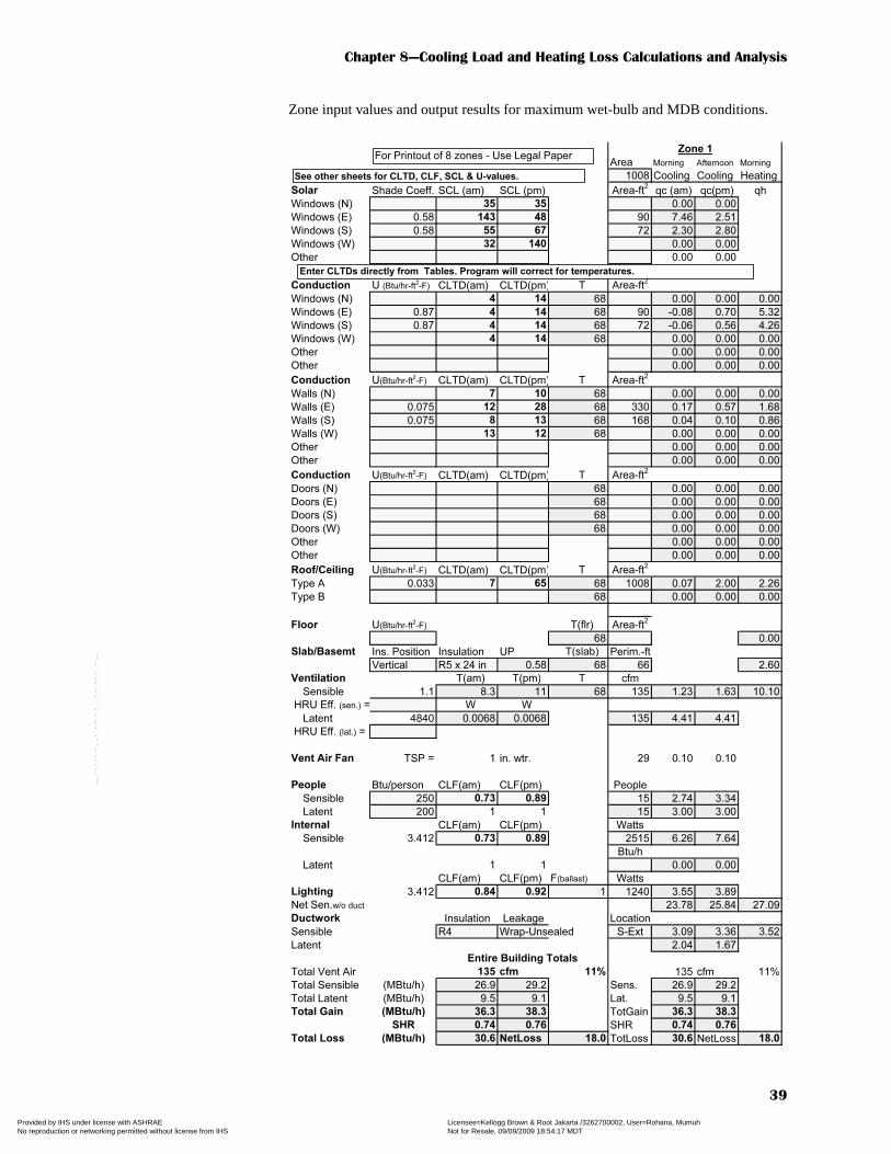
Chapter 8—Cooling Load and Heating Loss Calculations and Analysis
39
Zone input values and output results for maximum wet-bulb and MDB conditions.
Area Morning Afternoon Morning
1008 Cooling Cooling Heating
Solar Shade Coeff. SCL (am) SCL (pm) Area-ft2
qc (am) qc(pm) qh
Windows (N) 35 35 0.00 0.00
Windows (E) 0.58 143 48 90 7.46 2.51
Windows (S) 0.58 55 67 72 2.30 2.80
Windows (W) 32 140 0.00 0.00
Other 0.00 0.00
Conduction U (Btu/hr-ft2-F) CLTD(am) CLTD(pm) T Area-ft
2
Windows (N) 4 14 68 0.00 0.00 0.00
Windows (E) 0.87 4 14 68 90 -0.08 0.70 5.32
Windows (S) 0.87 4 14 68 72 -0.06 0.56 4.26
Windows (W) 4 14 68 0.00 0.00 0.00
Other 0.00 0.00 0.00
Other 0.00 0.00 0.00
Conduction U(Btu/hr-ft2-F) CLTD(am) CLTD(pm) T Area-ft
2
Walls (N) 7 10 68 0.00 0.00 0.00
Walls (E) 0.075 12 28 68 330 0.17 0.57 1.68
Walls (S) 0.075 8 13 68 168 0.04 0.10 0.86
Walls (W) 13 12 68 0.00 0.00 0.00
Other 0.00 0.00 0.00
Other 0.00 0.00 0.00
Conduction U(Btu/hr-ft2-F) CLTD(am) CLTD(pm) T Area-ft
2
Doors (N) 68 0.00 0.00 0.00
Doors (E) 68 0.00 0.00 0.00
Doors (S) 68 0.00 0.00 0.00
Doors (W) 68 0.00 0.00 0.00
Other 0.00 0.00 0.00
Other 0.00 0.00 0.00
Roof/Ceiling U(Btu/hr-ft2-F) CLTD(am) CLTD(pm) T Area-ft
2
Type A 0.033 7 65 68 1008 0.07 2.00 2.26
Type B 68 0.00 0.00 0.00
Floor U(Btu/hr-ft2-F) T(flr) Area-ft
2
68 0.00
Slab/Basemt Ins. Position Insulation UP T(slab) Perim.-ft
Vertical R5 x 24 in 0.58 68 66 2.60
Ventilation T(am) T(pm) T cfm
Sensible 1.1 8.3 11 68 135 1.23 1.63 10.10
HRU Eff. (sen.) = W W
Latent 4840 0.0068 0.0068 135 4.41 4.41
HRU Eff. (lat.) =
Vent Air Fan TSP = 1 in. wtr. 29 0.10 0.10
People Btu/person CLF(am) CLF(pm) People
Sensible 250 0.73 0.89 15 2.74 3.34
Latent 200 1 1 15 3.00 3.00
Internal CLF(am) CLF(pm) Watts
Sensible 3.412 0.73 0.89 2515 6.26 7.64
Btu/h
Latent 1 1 0.00 0.00
CLF(am) CLF(pm) F(ballast) Watts
Lighting 3.412 0.84 0.92 1 1240 3.55 3.89
Net Sen.w/o duct 23.78 25.84 27.09
Ductwork Insulation Leakage Location
Sensible R4 Wrap-Unsealed S-Ext 3.09 3.36 3.52
Latent 2.04 1.67
Total Vent Air 135 cfm 11% 135 cfm 11%
Total Sensible (MBtu/h) 26.9 29.2 Sens. 26.9 29.2
Total Latent (MBtu/h) 9.5 9.1 Lat. 9.5 9.1
Total Gain (MBtu/h) 36.3 38.3 TotGain 36.3 38.3
SHR 0.74 0.76 SHR 0.74 0.76
Total Loss (MBtu/h) 30.6 NetLoss 18.0 TotLoss 30.6 NetLoss 18.0
Entire Building Totals
Zone 1
Enter CLTDs directly from Tables. Program will correct for temperatures.
See other sheets for CLTD, CLF, SCL & U-values.
For Printout of 8 zones - Use Legal Paper
Copyright ASHRAE Provided by IHS under license with ASHRAE Licensee=Kellogg Brown & Root Jakarta /3262700002, User=Rohana, Mumuh
Not for Resale, 09/09/2009 18:54:17 MDTNo reproduction or networking permitted without license from IHS
--`,,``,`,,,`,,`,````,`,`,,,,``,-`-`,,`,,`,`,,`---
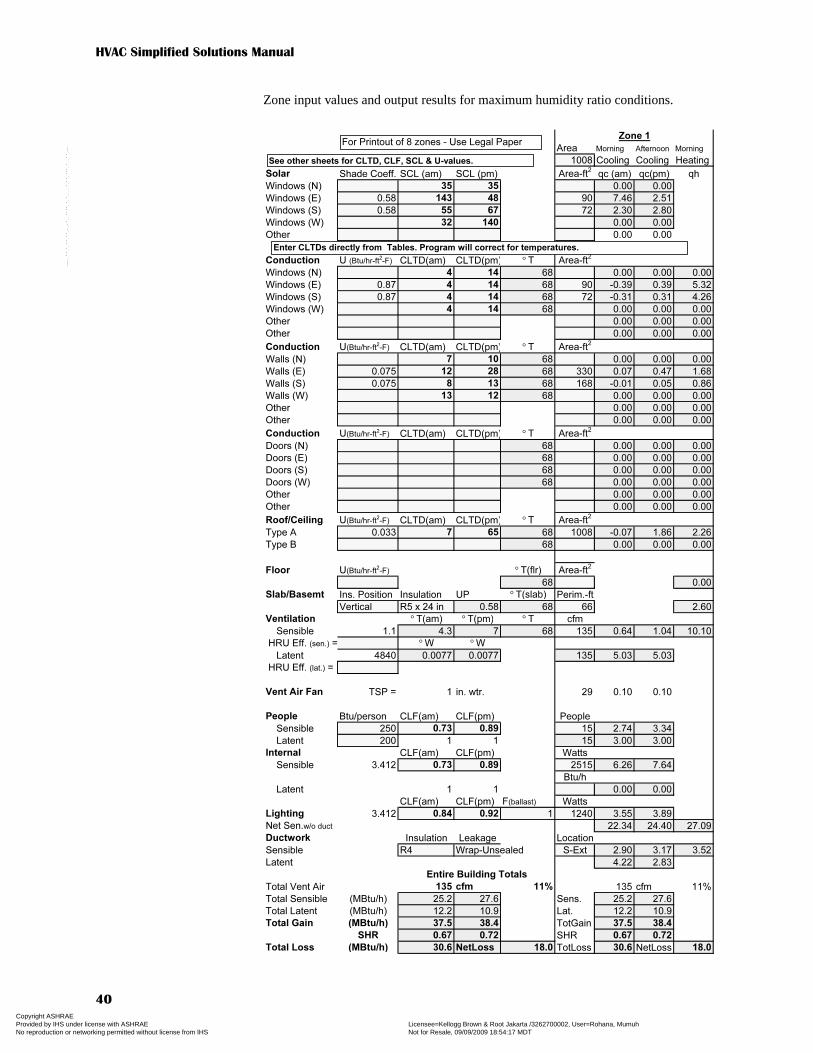
HVAC Simplified Solutions Manual
40
Zone input values and output results for maximum humidity ratio conditions.
Area Morning Afternoon Morning
1008 Cooling Cooling Heating
Solar Shade Coeff. SCL (am) SCL (pm) Area-ft2
qc (am) qc(pm) qh
Windows (N) 35 35 0.00 0.00
Windows (E) 0.58 143 48 90 7.46 2.51
Windows (S) 0.58 55 67 72 2.30 2.80
Windows (W) 32 140 0.00 0.00
Other 0.00 0.00
Conduction U (Btu/hr-ft2-F) CLTD(am) CLTD(pm) ° T Area-ft
2
Windows (N) 4 14 68 0.00 0.00 0.00
Windows (E) 0.87 4 14 68 90 -0.39 0.39 5.32
Windows (S) 0.87 4 14 68 72 -0.31 0.31 4.26
Windows (W) 4 14 68 0.00 0.00 0.00
Other 0.00 0.00 0.00
Other 0.00 0.00 0.00
Conduction U(Btu/hr-ft2-F) CLTD(am) CLTD(pm) ° T Area-ft
2
Walls (N) 7 10 68 0.00 0.00 0.00
Walls (E) 0.075 12 28 68 330 0.07 0.47 1.68
Walls (S) 0.075 8 13 68 168 -0.01 0.05 0.86
Walls (W) 13 12 68 0.00 0.00 0.00
Other 0.00 0.00 0.00
Other 0.00 0.00 0.00
Conduction U(Btu/hr-ft2-F) CLTD(am) CLTD(pm) ° T Area-ft
2
Doors (N) 68 0.00 0.00 0.00
Doors (E) 68 0.00 0.00 0.00
Doors (S) 68 0.00 0.00 0.00
Doors (W) 68 0.00 0.00 0.00
Other 0.00 0.00 0.00
Other 0.00 0.00 0.00
Roof/Ceiling U(Btu/hr-ft2-F) CLTD(am) CLTD(pm) ° T Area-ft
2
Type A 0.033 7 65 68 1008 -0.07 1.86 2.26
Type B 68 0.00 0.00 0.00
Floor U(Btu/hr-ft2-F) ° T(flr) Area-ft
2
68 0.00
Slab/Basemt Ins. Position Insulation UP ° T(slab) Perim.-ft
Vertical R5 x 24 in 0.58 68 66 2.60
Ventilation ° T(am) ° T(pm) ° T cfm
Sensible 1.1 4.3 7 68 135 0.64 1.04 10.10
HRU Eff. (sen.) = ° W ° W
Latent 4840 0.0077 0.0077 135 5.03 5.03
HRU Eff. (lat.) =
Vent Air Fan TSP = 1 in. wtr. 29 0.10 0.10
People Btu/person CLF(am) CLF(pm) People
Sensible 250 0.73 0.89 15 2.74 3.34
Latent 200 1 1 15 3.00 3.00
Internal CLF(am) CLF(pm) Watts
Sensible 3.412 0.73 0.89 2515 6.26 7.64
Btu/h
Latent 1 1 0.00 0.00
CLF(am) CLF(pm) F(ballast) Watts
Lighting 3.412 0.84 0.92 1 1240 3.55 3.89
Net Sen.w/o duct 22.34 24.40 27.09
Ductwork Insulation Leakage Location
Sensible R4 Wrap-Unsealed S-Ext 2.90 3.17 3.52
Latent 4.22 2.83
Total Vent Air 135 cfm 11% 135 cfm 11%
Total Sensible (MBtu/h) 25.2 27.6 Sens. 25.2 27.6
Total Latent (MBtu/h) 12.2 10.9 Lat. 12.2 10.9
Total Gain (MBtu/h) 37.5 38.4 TotGain 37.5 38.4
SHR 0.67 0.72 SHR 0.67 0.72
Total Loss (MBtu/h) 30.6 NetLoss 18.0 TotLoss 30.6 NetLoss 18.0
Entire Building Totals
Zone 1
Enter CLTDs directly from Tables. Program will correct for temperatures.
See other sheets for CLTD, CLF, SCL & U-values.
For Printout of 8 zones - Use Legal Paper
Copyright ASHRAE Provided by IHS under license with ASHRAE Licensee=Kellogg Brown & Root Jakarta /3262700002, User=Rohana, Mumuh
Not for Resale, 09/09/2009 18:54:17 MDTNo reproduction or networking permitted without license from IHS
--`,,``,`,,,`,,`,````,`,`,,,,``,-`-`,,`,,`,`,,`---

Solutions to Chapter 9—
Air Distribution System Design
Problem 9.1 Room 255 (Appendix C, Figure C.7*) has a 9 ft ceiling and an 18 × 20 ft floor.Select square ceiling diffusers to distribute 1400 cfm of air and provide an ADPI >90%, an NC < 30, and a TP < 0.1 in. of water. The solution should include a sketch.
Solution
Q = 1400 cfm: The shape of the room lends itself to two diffusers, 700 cfm each, thathave to throw air in near equal distance in four directions. A four-way diffuser isappropriate.To achieve an ADPI > 90%, T50/L = 1.4 to 2.7 with louvered ceiling diffusers
(Table 9.2)For L = 9 ft: T50 = (T50/L) · L = 1.4 · 9 = 12.6 ft to L = 2.7 · 9 = 24.3 ftFor L = 10 ft: T50 = 1.4 · 10 = 14.0 ft to L = 2.7 · 10 = 27.0 ftSo the diffuser must have a T50 between 14.0 and 24.3 ft in four directions
Try a 16 × 16 in. (Table 9.4): at 610 cfm T50 = 20 ft and at 765 cfm T50 = 25 ftVia interpolation: at 700 cfm T50 ≈ 23 ft → OK, and NC = 27 → OKTP = TPRated · (Q/QRated)2 = 0.094 · (700/765)2 = 0.079 in. of water → OK
Problem 9.2 Repeat Problem 9.1 for room 256 (Appendix C, Figure C.7*), which has a40 × 40 ft floor with 2200 cfm.
Solution
*See errata for HVAC Simplified posted to www.ashrae.org/publicationupdates for corrected Figure C.7.
Copyright ASHRAE Provided by IHS under license with ASHRAE Licensee=Kellogg Brown & Root Jakarta /3262700002, User=Rohana, Mumuh
Not for Resale, 09/09/2009 18:54:17 MDTNo reproduction or networking permitted without license from IHS
--`,,``,`,,,`,,`,````,`,`,,,,``,-`-`,,`,,`,`,,`---
HVAC Simplified Solutions Manual
42
To achieve an ADPI > 90%, T50/L = 1.4 to 2.7 with louvered ceiling diffusers(Table 9.2)
For L = 10 ft: T50 = 1.4 · 10 = 14.0 ft to L = 2.7 · 10 = 27.0 ftSo the diffuser must have a T50 between 14.0 and 27 ft in four directions
Try a 12 × 12 in. (Table 9.4): at 520 cfm T50 = 26 ft and at 610 cfm T50 = 30 ftVia interpolation: at 550 cfm T50 ≈ 27 ft and NC = 32 → too high, but may be
OK for VAV
Try a 14 × 14 in. (Table 9.4): at 500 cfm T50 = 19 ft and at 625 cfm T50 = 24 ftVia interpolation: at 550 cfm T50 ≈ 21 ft → OK, and NC = 25 → OKTP = TPRated · (Q/QRated)2 = 0.058 · (550/500)2 = 0.07 in. of water → OK
Problem 9.3 Size a MERV 6 filter and a matching filter-grille for room 255 (Appendix C,Figure C.7*) that will limit the final resistance to 0.5 in. of water. One dimensionshould be a multiple of 24 in. if possible.
Solution ΔhFinal ≤ 0.5 in. w.c. and recommendation is ΔhFinal ≈ 4 · ΔhInitialThus, Δhinitial = Δhfinal/4 = 0.5/4 = 0.125
For a MERV 6, 2 in. thick, pleated filter at 300 fpm, ΔhInitial = 0.13 in. w.c. (Table 9.7)V = VRated · (ΔhInitial/ΔhRated)0.5 = 300 · (0.125/0.13)0.5 = 294 fpmA = Q ÷ V = 1400 cfm ÷ 294 fpm = 4.76 ft2
W = 24 in. = 2.0 ft: H = 4.76 ft2 ÷ 2 ft = 2.38 ft = 29 in.Use 24 in. · 30 in. grille (Table 9.6): TP = 0.024 in. w.c. @ 1431 cfmTPGrille = TPRated · (Q/QRated)2 = 0.024 · (1400/1431)2 = 0.023 in. w.c
Problem 9.4 Repeat Problem 9.3 for room 256 (Appendix C, Figure C.7*).
Solution ΔhFinal ≤ 0.5 in. w.c. and recommendation is ΔhFinal ≈ 4 · ΔhInitial,thus ΔhInitial ≈ ΔhFinal ÷ 4 ≈ 0.5 ÷ 4 ≈ 0.125 in. w.c.
For a MERV 6, 2 in. thick, pleated filter at 300 fpm, ΔhInitial = 0.13 in. w.c. (Table 9.7)V = VRated · (ΔhInitial/ΔhRated)0.5 = 300 · (0.125/0.13)0.5 = 294 fpmA = Q ÷ V = 2200 cfm ÷ 294 fpm = 7.5 ft2
W = 24 in. = 2.0 ft: H = 7.5 ft2 ÷ 2 ft = 3.75 ft = 45 in.Use 24 in. · 48 in. grille (Table 9.6): TP = 0.024 in. w.c. @ 2307 cfmTPGrille = TPRated · (Q/QRated)2 = 0.024 · (2200/2307)2 = 0.022 in. w.c.
Problem 9.5 Select a unit to either fit in the hallway outside room 255 (Appendix C,Figure C.7*) or above the ceiling (42 in. vertical space) and route metal supplyductwork with round take-offs and metal return ductwork.
Solution
*See errata for HVAC Simplified posted to www.ashrae.org/publicationupdates for corrected Figure C.7.
Copyright ASHRAE Provided by IHS under license with ASHRAE Licensee=Kellogg Brown & Root Jakarta /3262700002, User=Rohana, Mumuh
Not for Resale, 09/09/2009 18:54:17 MDTNo reproduction or networking permitted without license from IHS
--`,,``,`,,,`,,`,````,`,`,,,,``,-`-`,,`,,`,`,,`---
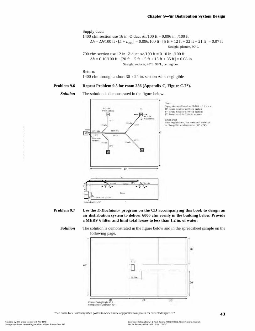
Chapter 9—Air Distribution System Design
43
Supply duct:1400 cfm section use 16 in. Ø duct Δh/100 ft = 0.096 in. /100 ft
Δh = Δh/100 ft · [L + Leqv] = 0.096/100 ft · [5 ft + 12 ft + 32 ft + 21 ft] = 0.07 ftStraight, plenum, 90°L
700 cfm section use 12 in. Ø duct Δh/100 ft = 0.10 in. /100 ftΔh = 0.10/100 ft · [20 ft + 5 ft + 5 ft + 15 ft + 35 ft] = 0.08 in.
Straight, reducer, 45°L, 90°L, ceiling box
Return:1400 cfm through a short 30 × 24 in. section Δh is negligible
Problem 9.6 Repeat Problem 9.5 for room 256 (Appendix C, Figure C.7*).
Solution The solution is demonstrated in the figure below.
Problem 9.7 Use the E-Ductulator program on the CD accompanying this book to design anair distribution system to deliver 6000 cfm evenly in the building below. Providea MERV 6 filter and limit total losses to less than 1.2 in. of water.
Solution The solution is demonstrated in the figure below and in the spreadsheet sample on thefollowing page.
*See errata for HVAC Simplified posted to www.ashrae.org/publicationupdates for corrected Figure C.7.
Copyright ASHRAE Provided by IHS under license with ASHRAE Licensee=Kellogg Brown & Root Jakarta /3262700002, User=Rohana, Mumuh
Not for Resale, 09/09/2009 18:54:17 MDTNo reproduction or networking permitted without license from IHS
--`,,``,`,,,`,,`,````,`,`,,,,``,-`-`,,`,,`,`,,`---
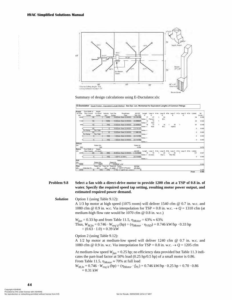
HVAC Simplified Solutions Manual
44
Summary of design calculations using E-Ductalator.xls:
Problem 9.8 Select a fan with a direct-drive motor to provide 1200 cfm at a TSP of 0.8 in. ofwater. Specify the required speed tap setting, resulting motor power output, andestimated required power demand.
Solution Option 1 (using Table 9.12):A 1/3 hp motor at high speed (1075 room) will deliver 1540 cfm @ 0.7 in. w.c. and1080 cfm @ 0.9 in. w.c. Via interpolation for TSP = 0.8 in. w.c. → Q = 1310 cfm (atmedium-high flow rate would be 1070 cfm @ 0.8 in. w.c.)
Wfan = 0.33 hp and from Table 11.5, ηMotor = 63% ≈ 63%Thus, WM,In = 0.746 · Wreq’d (hp) ÷ (ηMotor · ηVSD) = 0.746 kW/hp · 0.33 hp
÷ (0.63 · 1.0) = 0.39 kW
Option 2 (using Table 9.12):A 1/2 hp motor at medium-low speed will deliver 1240 cfm @ 0.7 in. w.c. and1080 cfm @ 0.9 in. w.c. Via interpolation for TSP = 0.8 in. w.c. → Q = 1205 cfm
At medium-low speed Wfan = 0.25 hp; no efficiency data provided but Table 11.3 indi-cates the part-load factor at 50% load (0.25 hp/0.5 hp) of a small motor is 0.86. From Table 11.5, ηMotor ≈ 70% at full loadWM,In = 0.746 · Wreq’d (hp) ÷ (ηMotor · fPL) = 0.746 kW/hp · 0.25 hp ÷ 0.70 · 0.86
= 0.31 kW
Supply Duct Width or Height
Air Flow Dia. if round 0 if round Velocity Hyd. Dia. Roughness Δh/100' Length Leqv A # As Leqv B # Bs Leqv C # Cs Leqv D # Ds L(total) Δh
cfm Inches Inches fpm Inches Feet "Wtr./100' ft. ft. ft. ft. ft. (in.wtr.)
2200 18 1245 18.0 Galv Steel (0.00025) 0.103156 17 37 1 24 54 0.056
Notes--> Plenum 90 L
1100 14 1029 14.0 Galv Steel (0.00025) 0.098927 12 10 1 22 0.022
Notes--> Red
550 12 700 12.0 Galv Steel (0.00025) 0.059537 18 13 1 15 1 35 1 81 0.048
Notes--> Wye 90 L topbox
1 16 1 16.0 Galv Steel (0.00025) 2.11E-07 0 0.000
For Sizing Par. Path Notes-->
1 10 2 10.0 Galv Steel (0.00025) 1.98E-06 0 0.000
For Sizing Par. Path Notes-->
1 1 183 1.0 Galv Steel (0.00025) 0.114782 0 0.000
Notes-->
1 1 183 1.0 Galv Steel (0.00025) 0.114782 0 0.000
Notes-->
Diffuser
cfm Rated cfm Rated Δh
550 500 0.058 0.070
Return Duct Width or Height
cfm Dia. if round 0 if round Δh/100' Length Leqv A # As Leqv B # Bs Leqv C # Cs Leqv D # Ds L(total)
2200 28 20 566 25.8 Galv Steel (0.00025) 0.01605 15 18 1 24 2 50 1 131 0.021
Notes--> Gr,trans Rad. L Plen Ret.
1 1 183 1.0 PVC (0.0001) 0.114484 0 0.000
Notes-->
Grill Notes:
cfm Rated cfm Rated Δh
2200 2307 0.024 48" x 24" 0.022
Filter Rated Vel Face Vel Rated Δh Notes: Δh final
cfm Area (sq. ft.) fpm fpm in. water 2" MERV 6 Pleated Δh clean
2200 8 300 275 0.13 0.13" @300 fpm (clean) 3 0.328
Total 0.566
E-Ductulator - Equal Friction - Equivalent Length Method - See Eqv. Len. Worksheet for Equivalent Lengths of Common Fittings
Copyright ASHRAE Provided by IHS under license with ASHRAE Licensee=Kellogg Brown & Root Jakarta /3262700002, User=Rohana, Mumuh
Not for Resale, 09/09/2009 18:54:17 MDTNo reproduction or networking permitted without license from IHS
--`,,``,`,,,`,,`,````,`,`,,,,``,-`-`,,`,,`,`,,`---
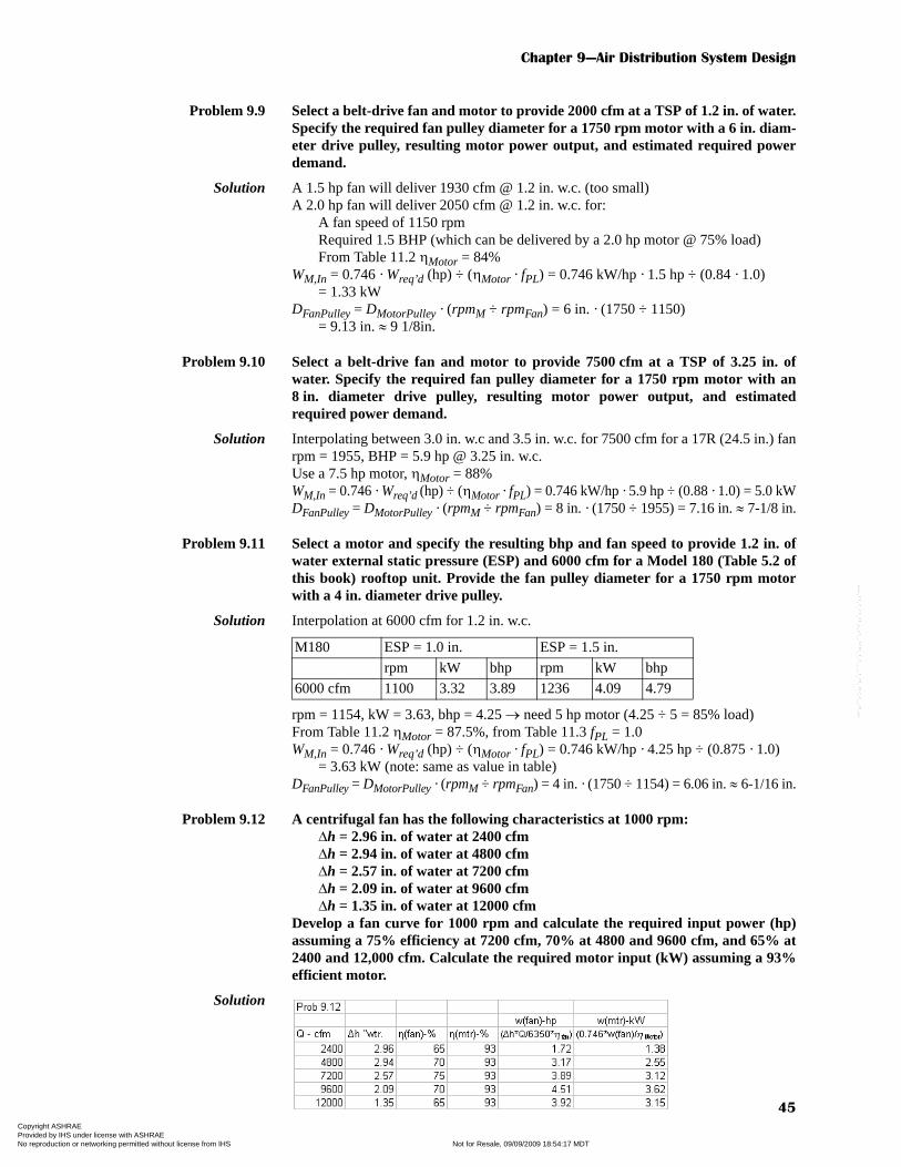
Chapter 9—Air Distribution System Design
45
Problem 9.9 Select a belt-drive fan and motor to provide 2000 cfm at a TSP of 1.2 in. of water.Specify the required fan pulley diameter for a 1750 rpm motor with a 6 in. diam-eter drive pulley, resulting motor power output, and estimated required powerdemand.
Solution A 1.5 hp fan will deliver 1930 cfm @ 1.2 in. w.c. (too small)A 2.0 hp fan will deliver 2050 cfm @ 1.2 in. w.c. for:
A fan speed of 1150 rpmRequired 1.5 BHP (which can be delivered by a 2.0 hp motor @ 75% load)From Table 11.2 ηMotor = 84%
WM,In = 0.746 · Wreq’d (hp) ÷ (ηMotor · fPL) = 0.746 kW/hp · 1.5 hp ÷ (0.84 · 1.0) = 1.33 kW
DFanPulley = DMotorPulley · (rpmM ÷ rpmFan) = 6 in. · (1750 ÷ 1150) = 9.13 in. ≈ 9 1/8in.
Problem 9.10 Select a belt-drive fan and motor to provide 7500 cfm at a TSP of 3.25 in. ofwater. Specify the required fan pulley diameter for a 1750 rpm motor with an8 in. diameter drive pulley, resulting motor power output, and estimatedrequired power demand.
Solution Interpolating between 3.0 in. w.c and 3.5 in. w.c. for 7500 cfm for a 17R (24.5 in.) fanrpm = 1955, BHP = 5.9 hp @ 3.25 in. w.c.Use a 7.5 hp motor, ηMotor = 88%WM,In = 0.746 · Wreq’d (hp) ÷ (ηMotor · fPL) = 0.746 kW/hp · 5.9 hp ÷ (0.88 · 1.0) = 5.0 kWDFanPulley = DMotorPulley · (rpmM ÷ rpmFan) = 8 in. · (1750 ÷ 1955) = 7.16 in. ≈ 7-1/8 in.
Problem 9.11 Select a motor and specify the resulting bhp and fan speed to provide 1.2 in. ofwater external static pressure (ESP) and 6000 cfm for a Model 180 (Table 5.2 ofthis book) rooftop unit. Provide the fan pulley diameter for a 1750 rpm motorwith a 4 in. diameter drive pulley.
Solution Interpolation at 6000 cfm for 1.2 in. w.c.
rpm = 1154, kW = 3.63, bhp = 4.25 → need 5 hp motor (4.25 ÷ 5 = 85% load)From Table 11.2 ηMotor = 87.5%, from Table 11.3 fPL = 1.0WM,In = 0.746 · Wreq’d (hp) ÷ (ηMotor · fPL) = 0.746 kW/hp · 4.25 hp ÷ (0.875 · 1.0)
= 3.63 kW (note: same as value in table)DFanPulley = DMotorPulley · (rpmM ÷ rpmFan) = 4 in. · (1750 ÷ 1154) = 6.06 in. ≈ 6-1/16 in.
Problem 9.12 A centrifugal fan has the following characteristics at 1000 rpm:Δh = 2.96 in. of water at 2400 cfmΔh = 2.94 in. of water at 4800 cfmΔh = 2.57 in. of water at 7200 cfmΔh = 2.09 in. of water at 9600 cfmΔh = 1.35 in. of water at 12000 cfm
Develop a fan curve for 1000 rpm and calculate the required input power (hp)assuming a 75% efficiency at 7200 cfm, 70% at 4800 and 9600 cfm, and 65% at2400 and 12,000 cfm. Calculate the required motor input (kW) assuming a 93%efficient motor.
Solution
M180 ESP = 1.0 in. ESP = 1.5 in. rpm kW bhp rpm kW bhp
6000 cfm 1100 3.32 3.89 1236 4.09 4.79
Copyright ASHRAE Provided by IHS under license with ASHRAE Licensee=Kellogg Brown & Root Jakarta /3262700002, User=Rohana, Mumuh
Not for Resale, 09/09/2009 18:54:17 MDTNo reproduction or networking permitted without license from IHS
--`,,``,`,,,`,,`,````,`,`,,,,``,-`-`,,`,,`,`,,`---
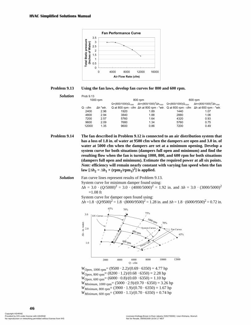
HVAC Simplified Solutions Manual
46
Problem 9.13 Using the fan laws, develop fan curves for 800 and 600 rpm.
Solution
Problem 9.14 The fan described in Problem 9.12 is connected to an air distribution system thathas a loss of 1.8 in. of water at 9500 cfm when the dampers are open and 3.0 in. ofwater at 5000 cfm when the dampers are set at a minimum opening. Develop asystem curve for both situations (dampers full open and minimum) and find theresulting flow when the fan is turning 1000, 800, and 600 rpm for both situations(dampers full open and minimum). Estimate the required power at all six points.Note: efficiency will remain nearly constant with varying fan speed when the fanlaw [Δh2 = Δh1 × (rpm2/rpm1)2] is applied.
Solution Fan curve lines represent results of Problem 9.13.System curve for minimum damper found using:Δh = 3.0 · (Q/5000)2 = 3.0 · (4000/5000)2 = 1.92 in. and Δh = 3.0 · (3000/5000)2
=1.08 ftSystem curve for damper open found using:Δh =1.8 · (Q/9500)2 = 1.8 · (8000/9500)2 = 1.28 in. and Δh = 1.8 · (6000/9500)2
= 0.72 in.
WOpen, 1000 rpm= (9500 · 2.2)/(0.69 · 6350) = 4.77 hpWOpen, 800 rpm= (8200 · 1.2)/(0.68 · 6350) = 2.28 hpWOpen, 600 rpm= (6000 · 0.8)/(0.69 · 6350) = 1.10 hpWMinimum, 1000 rpm= (5000 · 2.9)/(0.70 · 6350) = 3.26 hpWMinimum, 800 rpm= (3900 · 1.9)/(0.70 · 6350) = 1.67 hpWMinimum, 600 rpm= (3000 · 1.1)/(0.70 · 6350) = 0.74 hp
Fan Performance Curve
0
0.5
1
1.5
2
2.5
3
3.5
0 4000 8000 12000 16000
Air Flow Rate (cfm)
To
tal S
tati
c p
res
su
re
(In
ch
es
of
Wa
ter)
Prob 9.13
Q=(800/1000)Q1000 Δh=(800/1000)2Δh1000 Q=(800/1000)Q1000 Δh=(800/1000)
2Δh1000
Q - cfm Δh "wtr. Q at 800 rpm - cfm Δh at 800 rpm - "wtr. Q at 600 rpm - cfm Δh at 600 rpm - "wtr.
2400 2.96 1920 1.89 1440 1.07
4800 2.94 3840 1.88 2880 1.06
7200 2.57 5760 1.64 4320 0.93
9600 2.09 7680 1.34 5760 0.75
12000 1.35 9600 0.86 7200 0.49
1000 rpm 800 rpm 600 rpm
2000 4000 6000 8000 10000 12000
Q - cfm
Δh -
in. w
ate
r.
1.0
2.0
3.0
1000 rpm
800 rpm
600 rpmMim
imum
Dam
per
Damper Open
65%
75%
70%
70%
65%
System Curves
Eff. Curves
Fan Curves
Copyright ASHRAE Provided by IHS under license with ASHRAE Licensee=Kellogg Brown & Root Jakarta /3262700002, User=Rohana, Mumuh
Not for Resale, 09/09/2009 18:54:17 MDTNo reproduction or networking permitted without license from IHS
--`,,``,`,,,`,,`,````,`,`,,,,``,-`-`,,`,,`,`,,`---
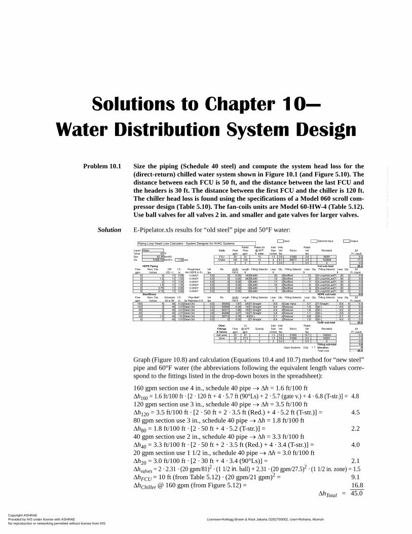
Solutions to Chapter 10—
Water Distribution System Design
Problem 10.1 Size the piping (Schedule 40 steel) and compute the system head loss for the(direct-return) chilled water system shown in Figure 10.1 (and Figure 5.10). Thedistance between each FCU is 50 ft, and the distance between the last FCU andthe headers is 30 ft. The distance between the first FCU and the chiller is 120 ft.The chiller head loss is found using the specifications of a Model 060 scroll com-pressor design (Table 5.10). The fan-coils units are Model 60-HW-4 (Table 5.12).Use ball valves for all valves 2 in. and smaller and gate valves for larger valves.
Solution E-Pipelator.xls results for “old steel” pipe and 50°F water:
Graph (Figure 10.8) and calculation (Equations 10.4 and 10.7) method for “new steel”pipe and 60°F water (the abbreviations following the equivalent length values corre-spond to the fittings listed in the drop-down boxes in the spreadsheet):
160 gpm section use 4 in., schedule 40 pipe → Δh = 1.6 ft/100 ftΔh160 = 1.6 ft/100 ft · [2 · 120 ft + 4 · 5.7 ft (90°Ls) + 2 · 5.7 (gate v.) + 4 · 6.8 (T-str.)] = 4.8120 gpm section use 3 in., schedule 40 pipe → Δh = 3.5 ft/100 ftΔh120 = 3.5 ft/100 ft · [2 · 50 ft + 2 · 3.5 ft (Red.) + 4 · 5.2 ft (T-str.)] = 4.580 gpm section use 3 in., schedule 40 pipe → Δh = 1.8 ft/100 ftΔh80 = 1.8 ft/100 ft · [2 · 50 ft + 4 · 5.2 (T-str.)] = 2.240 gpm section use 2 in., schedule 40 pipe → Δh = 3.3 ft/100 ftΔh40 = 3.3 ft/100 ft · [2 · 50 ft + 2 · 3.5 ft (Red.) + 4 · 3.4 (T-str.)] = 4.020 gpm section use 1 1/2 in., schedule 40 pipe → Δh = 3.0 ft/100 ftΔh20 = 3.0 ft/100 ft · [2 · 30 ft + 4 · 3.4 (90°Ls)] = 2.1Δhvalves = 2 · 2.31 · (20 gpm/81)2 · (1 1/2 in. ball) + 2.31 · (20 gpm/27.5)2 · (1 1/2 in. zone) = 1.5ΔhFCU = 10 ft (from Table 5.12) · (20 gpm/21 gpm)2 = 9.1ΔhChiller @ 160 gpm (from Figure 5.12) = 16.8
ΔhTotal = 45.0
Input Optional Input Output
Rated Rated Δh Inlet Inlet Rated
Liquid Water Coils Flow Flow @ 60ºF Size Vel Re(in) Vel Re(rated) Δh
Temp 50 ºF gpm gpm ft. water inches fps fps Ft. Liquid
Den 62.38 lbm/ft3 FCU 20 21 10 1.5 3.6 31892 3.8 38381 9.2
Vis 8.88E-04 lbm/ft-s 1.32 cps Chiller 160 150 15 4 4.1 95677 3.8 102808 17.2
0 0 0 0 0.0 0 0.0 0 0.0
HDPE Piping Coil sub-total 26.4
Flow Nom. Dia. DR I.D. Roughness Vel Re Δh(ft) Length Fitting Selector Leqv Qty. Fitting Selector Leqv Qty. Fitting Selector Leqv Qty. Δh
gpm Inches OD ÷ t in. (for HDPE in ft.) fps 100 ft. ft. ft ft ft Ft. Liquid
0 4 11 3.68 0.00007 0.0 0 0.00 160 Butt90 35 2 ButtRed 13 2 5-LoopHdrLastTO 30 2 0.0
0 1.5 11 1.55 0.00007 0.0 0 0.00 390 Butt90 12 2 ButtRed 6 2 5-LoopHdrLastTO 30 2 0.0
0 2 11 1.94 0.00007 0.0 0 0.00 0 Butt90 17 2 ButtRed 7 2 5-LoopHdrLastTO 30 2 0.0
0 1.5 11 1.55 0.00007 0.0 0 0.00 0 Butt90 12 2 ButtRed 6 2 5-LoopHdrLastTO 30 2 0.0
0 0.75 11 0.86 0.00007 0.0 0 0.00 0 Butt90 5 2 ButtRed 4 2 5-LoopHdrLastTO 30 2 0.0
0 0.75 11 0.86 0.00007 0.0 0 0.00 0 Butt90 5 2 ButtRed 4 2 5-LoopHdrLastTO 30 2 0.0
Steel/Brass HDPE sub-total 0.0
Flow Nom. Dia. Schedule I.D. Pipe Mat'l Vel Re Δh(ft) Length Fitting Selector Leqv Qty. Fitting Selector Leqv Qty. Fitting Selector Leqv Qty. Δh
gpm Inches 40 or 80 in. for Rghness in ft. fps 100 ft. ft. ft ft ft Ft. Liquid
160 4 40 4.03 Steel-Old 4.0 95059 1.87 240 T-Straight 6.8 4 Gate Valve 5.7 2 T-Straight 6.8 4 5.7
120 3 40 3.07 Steel-Old 5.2 93556 4.34 100 T-Straight 5.4 2 Reducer 1.8 2 90 L 4.5 0 5.0
80 3 40 3.07 Steel-Old 3.5 62371 1.98 100 T-Straight 5.4 4 Reducer 1.8 2 90 L 4.5 0 2.5
40 2 40 2.07 Steel-Old 3.8 46288 3.97 100 T-Straight 3.4 4 Reducer 1.1 2 90 L 2.8 0 4.6
20 1.5 40 1.61 Steel-Old 3.2 29713 3.79 60 90 L 2.1 4 Reducer 0.8 2 90 L 2.1 0 2.7
0 3 40 3.07 Steel-Old 0.0 0 0.00 0 T-Straight 5.4 2 Reducer 1.8 0 90 L 4.5 0 0.0
Fe/Br sub-total 20.4
Other Cv Inlet Inlet Rated
Fittings Flow @ 60ºF Quanity Size Vel Re(in) Vel Re(rated) Δh
& Valves gpm gpm inches fps fps Ft. Liquid
ball valve 20 81 2 1.5 3.6 31892 14.7 148043 0.3
Zone 20 27.5 1 1.5 3.6 31892 5.0 50261 1.3
0 0 0 2 0.0 0 0.0 0 0.0
Fitting sub-total 1.6
Open Systems Only ? ? Elevation 0
Total Loss 48.4
Piping Loop Head Loss Calculator - System Designer for HVAC Systems
Copyright ASHRAE Provided by IHS under license with ASHRAE Licensee=Kellogg Brown & Root Jakarta /3262700002, User=Rohana, Mumuh
Not for Resale, 09/09/2009 18:54:17 MDTNo reproduction or networking permitted without license from IHS
--`,,``,`,,,`,,`,````,`,`,,,,``,-`-`,,`,,`,`,,`---

HVAC Simplified Solutions Manual
48
Problem 10.1 with pipe sizes
Problem 10.2 Select a chilled water pump and corresponding motor for the system describedin Problem 10.1.
Solution The system requires a pump that will deliver a 160 gpm flow rate and 45 ft of head,assuming the water treatment program will be good to maintain the condition of thepipe. In this case, a Model #2-1/2 AB pump (Figure 10.14) with a 7 in. diameterimpeller will provide 46.5 ft of head at 160 gpm. It will require approximately2.8 bhp, so a 3 hp, 1750 rpm motor will suffice. Note the selected pump will operatenear 73% efficiency, which is near the maximum efficiency point (MEP) of 75.5%.
If the water treatment program is uncertain, the old steel pipe roughness and head loss(48.4 ft) should be assumed. Although a Model 5x5x9-3/4B pump with a 7-3/4 in,impeller will provide adequate flow and head, it is not a good choice. Note the effi-ciency at the resulting operating point is only about 45%—well below its MEP of79.5%. A more extensive set of pump curves should be consulted to select a pumpthat will operate at a more favorable efficiency.
Problem 10.3 Size the piping, compute the required head, and select a pump and motor for thecondenser water loop shown in Figure 10.3. Use the Model 060 chiller fromProblem 10.1 with a flow rate of 200 gpm. Use SDR 11 high-density polyethyleneto eliminate corrosion in this open loop. The distance between the basin andupper tray in the cooling tower is 12 ft.
Solution Graph (Figure 10.9) and calculation (Equation 10.4) method for HDPE pipe:
200 gpm use 4 in., DR11 pipe → Δh = 3.3 ft/100 ftΔh160 = 3.3 ft/100 ft · [2 · 250 + 12 ft + 6 · 38 ft (90°Ls) + 4 · 5.7 (gate v.)] = 25.2Elevation = 12.0ΔhCondenser @ 200 gpm (from Figure 5.15) = 12.5
ΔhTotal = 49.0 ft.
The Model 5x5x9-3/4B pump with a 7-3/4 in. impellor will provide 54 ft at 200 gpmbut is not a good choice. Note the efficiency at the resulting operating point is onlyabout 56%, well below its MEP of 79.5%. A more extensive set of pump curvesshould be consulted to select a pump that will operate at a more favorable efficiency.If the pump is used, a 5 hp/1750 rpm motor is acceptable.
Copyright ASHRAE Provided by IHS under license with ASHRAE Licensee=Kellogg Brown & Root Jakarta /3262700002, User=Rohana, Mumuh
Not for Resale, 09/09/2009 18:54:17 MDTNo reproduction or networking permitted without license from IHS
--`,,``,`,,,`,,`,````,`,`,,,,``,-`-`,,`,,`,`,,`---
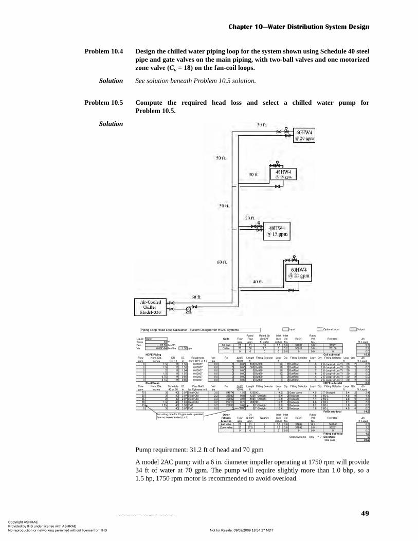
Chapter 10—Water Distribution System Design
49
Problem 10.4 Design the chilled water piping loop for the system shown using Schedule 40 steelpipe and gate valves on the main piping, with two-ball valves and one motorizedzone valve (Cv = 18) on the fan-coil loops.
Solution See solution beneath Problem 10.5 solution.
Problem 10.5 Compute the required head loss and select a chilled water pump forProblem 10.5.
Solution
Pump requirement: 31.2 ft of head and 70 gpm
A model 2AC pump with a 6 in. diameter impeller operating at 1750 rpm will provide34 ft of water at 70 gpm. The pump will require slightly more than 1.0 bhp, so a1.5 hp, 1750 rpm motor is recommended to avoid overload.
Input Optional Input Output
Rated Rated Δh Inlet Inlet Rated
Liquid Water Coils Flow Flow @ 60ºF Size Vel Re(in) Vel Re(rated) Δh
Temp 50 ºF gpm gpm ft. water inches fps fps Ft. Liquid
Den 62.38 lbm/ft3 60HW4 20 21 10 1.5 3.6 31892 3.8 38381 9.2
Vis 8.88E-04 lbm/ft-s 1.32 cps Chiller 70 80 7.5 3 3.2 55811 3.6 73108 5.9
0 0 0 0 0.0 0 0.0 0 0.0
HDPE Piping Coil sub-total 15.1
Flow Nom. Dia. DR I.D. Roughness Vel Re Δh(ft) Length Fitting Selector Leqv Qty. Fitting Selector Leqv Qty. Fitting Selector Leqv Qty. Δh
gpm Inches OD ÷ t in. (for HDPE in ft.) fps 100 ft. ft. ft ft ft Ft. Liquid
0 1.5 11 1.55 0.00007 0.0 0 0.00 160 Butt90 12 2 ButtRed 6 2 5-LoopHdrLastTO 30 2 0.0
0 1.5 11 1.55 0.00007 0.0 0 0.00 390 Butt90 12 2 ButtRed 6 2 5-LoopHdrLastTO 30 2 0.0
0 2 11 1.94 0.00007 0.0 0 0.00 0 Butt90 17 2 ButtRed 7 2 5-LoopHdrLastTO 30 2 0.0
0 1.5 11 1.55 0.00007 0.0 0 0.00 0 Butt90 12 2 ButtRed 6 2 5-LoopHdrLastTO 30 2 0.0
0 0.75 11 0.86 0.00007 0.0 0 0.00 0 Butt90 5 2 ButtRed 4 2 5-LoopHdrLastTO 30 2 0.0
0 0.75 11 0.86 0.00007 0.0 0 0.00 0 Butt90 5 2 ButtRed 4 2 5-LoopHdrLastTO 30 2 0.0
Steel/Brass HDPE sub-total 0.0
Flow Nom. Dia. Schedule I.D. Pipe Mat'l Vel Re Δh(ft) Length Fitting Selector Leqv Qty. Fitting Selector Leqv Qty. Fitting Selector Leqv Qty. Δh
gpm Inches 40 or 80 in. for Rghness in ft. fps 100 ft. ft. ft ft ft Ft. Liquid
70 3 40 3.07 Steel-Old 3.0 54574 1.53 120 90 L 4.5 2 Gate Valve 4.5 3 T-Straight 5.4 2 2.4
50 3 40 3.07 Steel-Old 2.2 38982 0.81 120 T-Straight 5.4 2 Reducer 1.8 0 90 L 4.5 0 1.1
35 2 40 2.07 Steel-Old 3.3 40502 3.07 100 T-Straight 3.4 2 Reducer 1.1 2 90 L 2.8 0 3.3
20 1.5 40 1.61 Steel-Old 3.2 29713 3.79 200 90 L 2.1 2 Reducer 0.8 2 90 L 2.1 0 7.8
15 1.25 40 1.38 PVC 3.2 25999 3.62 0 T-Straight 2.2 0 Reducer 0.7 0 90 L 1.8 0 0.0
0 3 40 3.07 PVC 0.0 0 0.00 0 T-Straight 5.4 2 Reducer 1.8 0 90 L 4.5 0 0.0
Fe/Br sub-total 14.5
Other Cv Inlet Inlet Rated
Fittings Flow @ 60ºF Quanity Size Vel Re(in) Vel Re(rated) Δh
& Valves gpm gpm inches fps fps Ft. Liquid
ball valve 20 81 2 1.5 3.6 31892 14.7 148043 0.3
Zone valve 20 27.5 1 1.5 3.6 31892 5.0 50261 1.3
0 0 0 2 0.0 0 0.0 0 0.0
Fitting sub-total 1.6
Open Systems Only ? ? Elevation 0
Total Loss 31.2
Piping Loop Head Loss Calculator - System Designer for HVAC Systems
For sizing pipe for 15 gpm coils - parallel
flow no losses added (L= 0)
Copyright ASHRAE Provided by IHS under license with ASHRAE Licensee=Kellogg Brown & Root Jakarta /3262700002, User=Rohana, Mumuh
Not for Resale, 09/09/2009 18:54:17 MDTNo reproduction or networking permitted without license from IHS
--`,,``,`,,,`,,`,````,`,`,,,,``,-`-`,,`,,`,`,,`---

Copyright ASHRAE Provided by IHS under license with ASHRAE Licensee=Kellogg Brown & Root Jakarta /3262700002, User=Rohana, Mumuh
Not for Resale, 09/09/2009 18:54:17 MDTNo reproduction or networking permitted without license from IHS
--`,,``,`,,,`,,`,````,`,`,,,,``,-`-`,,`,,`,`,,`---
Solutions to Chapter 11—
Motors, Lighting, and Controls
Problem 11.1 An air system design requires 6600 cfm with 3.0 in. of water (static pressure).Find the required motor size, drive pulley diameter (if the blower wheel has a12 in. diameter pulley and the motor is 4-pole), fan efficiency, and motordemand.
Solution A 17R fan (Table 9.13) will deliver:6000 cfm and 3.0 in. TSP when operating at 1730 rpm and requiring 4.33 bhp7500 cfm and 3.0 in. TSP when operating at 1920 rpm and requiring 5.68 bhpVia linear interpolation to the operating requirement:6600 cfm and 3.0 in. TSP when operating at 1810 rpm and requiring 4.9 bhp
Use 5 hp, 1725 rpm motor (ηMotor = 86.5%) from Table 11.5Note: rpm ≈ 7200 ÷ no. of poles ≈ 7200 ÷ 4 ≈ 1800 rpm
Problem 11.2 Compute the demand, KVA, and KVAR of a 6-pole, 20 hp motor at 100%, 75%,and 50% load.
Solution rpm ≈ 7200 ÷ no. of poles ≈ 7200 ÷ 6 ≈ 1200 rpm, 20 hpFrom Table 11.2, ηMotor = 91.0%From Table 11.3, fPL-100% = 1.0, fPL-75% = 1.0, fPL-50% = 0.99From Table 11.4, PF100% = 0.84, PF75% = 0.81, PF50% = 0.74
For 100% load,
For 75% load,
ηfanQ (cfm) p (in. water)Δ⋅
6350 bhp⋅---------------------------------------------------------
6600 (cfm) 3.0 (in. water)⋅
6350 4.9⋅------------------------------------------------------------------ 0.636 63.6%= = = =
DMotor DFan
rpmFan
rpmMotor-----------------------⋅ 12 in.
18101725------------⋅ 12.6 in. 12 5/8 in.= = = =
WMotorIn
0.746 kW/hp WReq'd (hp)⋅
ηMotor fPL⋅----------------------------------------------------------------
0.746 kW/hp 4.9 (hp)⋅
0.865 1.0⋅------------------------------------------------------- 4.2 kW= = =
WMotorIn0.746 kW/hp 20 (hp)⋅
0.91 1.0⋅
------------------------------------------------------ 16.4 kW I,WMotorIn
3 E PF⋅ ⋅
----------------------------16 400 W,
3 230 0.84⋅ ⋅
----------------------------------- 49.0 amps= = = = =
WMotorIn0.746 kW/hp 0.75 20 (hp)⋅ ⋅
0.91 1.0⋅
--------------------------------------------------------------------- 12.3 kW I,WMotorIn
3 E PF⋅ ⋅
----------------------------
12 300 W,
3 230 0.81⋅ ⋅
----------------------------------- 38.1 amps= = = = =
Copyright ASHRAE Provided by IHS under license with ASHRAE Licensee=Kellogg Brown & Root Jakarta /3262700002, User=Rohana, Mumuh
Not for Resale, 09/09/2009 18:54:17 MDTNo reproduction or networking permitted without license from IHS
--`,,``,`,,,`,,`,````,`,`,,,,``,-`-`,,`,,`,`,,`---

HVAC Simplified Solutions Manual
52
For 50% load,
Problem 11.3 Compute the demand, KVA, and KVAR of a 2-pole, 15 hp motor at 100%, 75%,and 50% load.
Solution rpm ≈ 7200 ÷ no. of poles ≈ 7200 ÷ 2 ≈ 3600 rpm, 15 hpFrom Table 11.2, ηMotor = 89.5%From Table 11.3, fPL-100% = 1.0, fPL-75% = 1.0, fPL-50% = 0.99From Table 11.4, PF100% = 0.89, PF75% = 0.88, PF50% = 0.84
For 100% load,
For 75% load,
For 50% load,
Problem 11.4 A 30 DE-25 in. fan is operated at 1195 rpm to deliver 10,000 cfm at 3.5 in. ofwater. Select an 1800 rpm motor to drive this fan and specify resulting demand(kW), KVA, and KVAR at the design point and at 6,000 cfm.
Solution 30 DE-25 in. fan at 1195 rpm, 10,000 cfm, and 3.5 in. TSPbhp = 7.84, use 10 hp motor @ 78% loadFrom Table 11.2, ηMotor = 89.5%From Table 11.3, fPL-78% = 1.0From Table 11.4, PF78% = 0.83
For 78% load,
Problem 11.5 Repeat Problem 11.4 if a motor one size larger than required is specified.
Solution For a 30 DE-25 in. fan at 1195 rpm, 10,000 cfm, and 3.5 in. TSPbhp = 7.84, but use 15 hp motor @ 52% loadFrom Table 11.2, ηMotor = 91.0%From Table 11.3, fPL-52% = 0.99From Table 11.4, PF52% = 0.78
For 78% load,
WMotorIn0.746 kW/hp 0.50 20 (hp)⋅ ⋅
0.91 0.99⋅
--------------------------------------------------------------------- 8.28 kW I,WMotorIn
3 E PF⋅ ⋅
----------------------------
8 280 W,
3 230 0.74⋅ ⋅
----------------------------------- 28.1 amps= = = = =
WMotorIn0.746 kW/hp 15 (hp)⋅
0.895 1.0⋅
------------------------------------------------------ 12.5 kW I,WMotorIn
3 E PF⋅ ⋅
----------------------------12 500 W,
3 460 0.89⋅ ⋅
----------------------------------- 17.6 amps= = = = =
WMotorIn0.746 kW/hp 0.75 15 (hp)⋅ ⋅
0.895 1.0⋅
--------------------------------------------------------------------- 9.38 kW I,WMotorIn
3 E PF⋅ ⋅
----------------------------
9380 W
3 230 0.88⋅ ⋅
----------------------------------- 13.4 amps= = = = =
WMotorIn0.746 kW/hp 0.50 15 (hp)⋅ ⋅
0.895 0.99⋅
--------------------------------------------------------------------- 6.31 kW I,WMotorIn
3 E PF⋅ ⋅
----------------------------
8 280 W,
3 460 0.84⋅ ⋅
----------------------------------- 9.4 amps= = = = =
WMotorIn0.746 kW/hp 0.78 10 (hp)⋅ ⋅
0.895 1.0⋅
--------------------------------------------------------------------- 6.5 kW I,WMotorIn
3 E PF⋅ ⋅
----------------------------
6500 W
3 230 0.83⋅ ⋅
----------------------------------- 19.7 amps= = = = =
WMotorIn0.746 kW/hp 0.52 15 (hp)⋅ ⋅
0.91 0.99⋅
---------------------------------------------------------------------- 6.5 kW I,WMotorIn
3 E PF⋅ ⋅
----------------------------6500 W
3 230 0.78⋅ ⋅
----------------------------------- 20.8 amps= = = = =
Copyright ASHRAE Provided by IHS under license with ASHRAE Licensee=Kellogg Brown & Root Jakarta /3262700002, User=Rohana, Mumuh
Not for Resale, 09/09/2009 18:54:17 MDTNo reproduction or networking permitted without license from IHS
--`,,``,`,,,`,,`,````,`,`,,,,``,-`-`,,`,,`,`,,`---

Chapter 11—Motors, Lighting, and Controls
53
Problem 11.6 A pump that operates 3000 hours per year and requires 400 gpm and 55 ft ofhead is significantly oversized. The curve of the existing pump is shown in Figure10.12. The impellor diameter is 9.75 in. and the motor is 20 hp. The requiredflow rate is attained by throttling the pump discharge valve.
a. Estimate the required horsepower and compute the resulting motor effi-ciency and power demand at the throttled position.
b. Estimate the required horsepower and compute the resulting motor effi-ciency and power demand for the 20 hp motor if the pump impellor wastrimmed to a size shown on the curve that provides the needed flow andhead.
c. Estimate the required horsepower and compute the resulting motor effi-ciency and power demand for the adequately sized motor if the pumpimpellor was trimmed.
d. Estimate the annual energy consumption for the three above options.For a cost of $500 to trim the impellor and $1000 to purchase and replace themotor, estimate the simple payback for the options in 11.6b and 11.6c.
Solution a. For a Model 5x5x9-3/4 pump with a 9-3/4 in. impeller:@ 400 gpm, Δh = 88 ft, ηpump = 73%Wreq’d = 400 · 88 ft (3960 · 0.73) = 12.2 hpFor 20 hp motor, %Load = 12.2 hp ÷ 20 hp = 61%ηMotor = 91%, fPL = 1.0WMotorIn = 0.746 · 12.2 ÷ (0.91 · 1.0) = 10.0 kW
b. For a Model 5x5x9-3/4 pump with an 8-1/4 in. impeller:@ 400 gpm, Δh = 55 ft, ηpump = 75%Wreq’d = 400 · 55 ft (3960 · 0.75) = 7.4 hpFor 20 hp motor, %Load = 7.4 hp ÷ 20 hp = 37%ηMotor = 91%, fPL = 0.96WMotorIn = 0.746 · 7.4 ÷ (0.91 · 0.96) = 6.3 kW
c. For a Model 5x5x9-3/4 pump with an 8-1/4 in. impeller and either 7.5 or 10 hpmotor:@ 400 gpm, Δh = 55 ft, ηpump = 75%Wreq’d = 400 · 55 ft (3960 · 0.75) = 7.4 hpFor 7.5 hp motor, ηMotor = 88.5%, fPL = 1.0WMotorIn = 0.746 · 7.4 ÷ (0.885 · 1.0) = 6.2 kW
d. For a., E = 3000 h · 10 kW = 30,000 kWhFor b., E = 3000 h · 6.3 kW = 18,900 kWhFor c., E = 3000 h · 6.2 kW = 18,600 kWh
Problem 11.7 Design a lighting system for a 30 × 40 ft classroom using 2-bulb, 48-in. T-8 fluo-rescent lighting fixtures with electronic ballasts.
Solution Classroom illumination is D or E (Table 11.8).Try higher level first (E, illumination = 750 lumens/m2 or 75 lumens/ft2).A 48-in.-long T-8 lamp, 2710 lumens (mean), 31 W (Table 11.11)Each two-bulb fixture provides 5420 lumens and requires 62 W.Luminaries = 75 lumens/ft2 · 1200 ft2 ÷ 5420 lumens/fixture = 16.6 fixtures
→ Use 17 or 18
Copyright ASHRAE Provided by IHS under license with ASHRAE Licensee=Kellogg Brown & Root Jakarta /3262700002, User=Rohana, Mumuh
Not for Resale, 09/09/2009 18:54:17 MDTNo reproduction or networking permitted without license from IHS
--`,,``,`,,,`,,`,````,`,`,,,,``,-`-`,,`,,`,`,,`---

HVAC Simplified Solutions Manual
54
Problem 11.8 Compare the demand of the resulting design for problem 11.7 with ASHRAEStandard 90.1-2004 limits for this application.
Solution For 18 bulbs: W = 18 fixtures · 62 W/fixture = 1116 WLPD = 1116 W ÷ 1200 ft2 = 0.93 W/ ft2
From Table 11.10, LPDClassroom = 1.4 W/ ft2
Design complies with ASHRAE Standard 90.1-2004 since 0.93 W/ft2 < 1.4 W/ft2.
Problem 11.9 A 1000 ft2 storage area is currently lit with standard 100-W incandescent bulbsto an illumination of 30 footcandles for 80 hours per week. Compare the annualoperating cost of using existing bulbs and replacing them with equivalent light-ing output compact fluorescent bulbs. Include operating cost (at 8¢/kWh), cost ofbulbs (at $3.00 each), and installation cost (1 hour at $20/hour labor).
Solution For 100-W incandescent bulbs that provide 1710 lumens each with an average life of750 hours:Luminaries = 30 lumens/ft2 · 1000 ft2 ÷ 1710 lumens/bulb = 18 bulbsW = 18 · 100 W = 1800 W
For compact fluorescent bulbs, use 26-W (33-W actual), which provide 1700 lumenseach with an average life of 12,000 hours.
Annual Cost 80 h 52 weeks1800 W
1000 W/kW----------------------------- 0.08 $/kW
18 bulbs $0.30⋅
750 h---------------------------------------
$20/h750 h-------------+ +⋅⋅ $740 yr= =
Annual Cost 80 h 52 weeks33 18⋅ W
1000 W/kW----------------------------- 0.08 $/kW
18 bulbs $3.00⋅
12000 h---------------------------------------
$20/h12000 h-------------------+ +⋅⋅ $223 yr= =
Copyright ASHRAE Provided by IHS under license with ASHRAE Licensee=Kellogg Brown & Root Jakarta /3262700002, User=Rohana, Mumuh
Not for Resale, 09/09/2009 18:54:17 MDTNo reproduction or networking permitted without license from IHS
--`,,``,`,,,`,,`,````,`,`,,,,``,-`-`,,`,,`,`,,`---
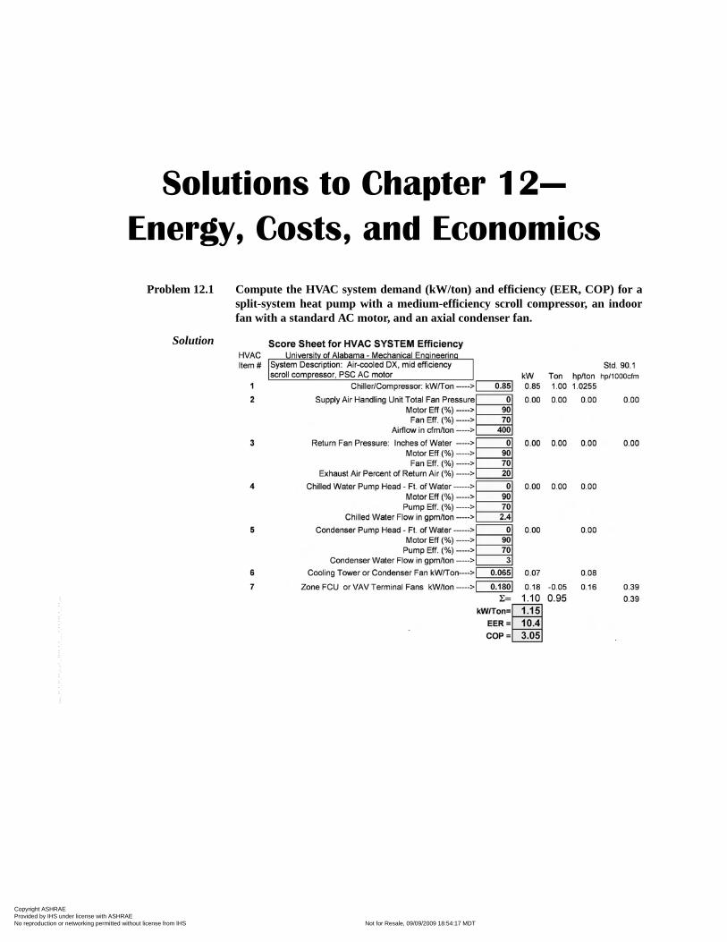
Solutions to Chapter 12—
Energy, Costs, and Economics
Problem 12.1 Compute the HVAC system demand (kW/ton) and efficiency (EER, COP) for asplit-system heat pump with a medium-efficiency scroll compressor, an indoorfan with a standard AC motor, and an axial condenser fan.
Solution
Copyright ASHRAE Provided by IHS under license with ASHRAE Licensee=Kellogg Brown & Root Jakarta /3262700002, User=Rohana, Mumuh
Not for Resale, 09/09/2009 18:54:17 MDTNo reproduction or networking permitted without license from IHS
--`,,``,`,,,`,,`,````,`,`,,,,``,-`-`,,`,,`,`,,`---
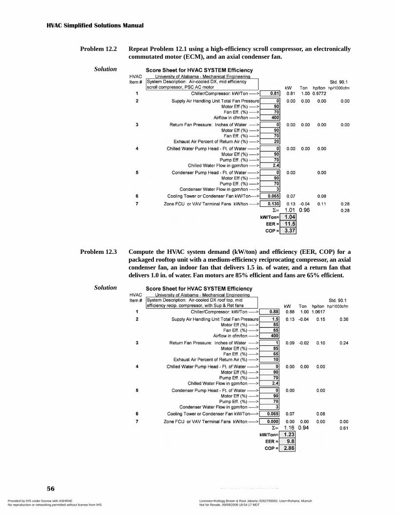
HVAC Simplified Solutions Manual
56
Problem 12.2 Repeat Problem 12.1 using a high-efficiency scroll compressor, an electronicallycommutated motor (ECM), and an axial condenser fan.
Solution
Problem 12.3 Compute the HVAC system demand (kW/ton) and efficiency (EER, COP) for apackaged rooftop unit with a medium-efficiency reciprocating compressor, an axialcondenser fan, an indoor fan that delivers 1.5 in. of water, and a return fan thatdelivers 1.0 in. of water. Fan motors are 85% efficient and fans are 65% efficient.
Solution
Copyright ASHRAE Provided by IHS under license with ASHRAE Licensee=Kellogg Brown & Root Jakarta /3262700002, User=Rohana, Mumuh
Not for Resale, 09/09/2009 18:54:17 MDTNo reproduction or networking permitted without license from IHS
--`,,``,`,,,`,,`,````,`,`,,,,``,-`-`,,`,,`,`,,`---

Chapter 12—Energy, Costs, and Economics
57
Problem 12.4 Compute the HVAC system demand (kW/ton) and efficiency (EER, COP) for aground-source heat pump using a high-efficiency scroll compressor, a fan withan ECM, and a 50% efficient pump with a 60% electric motor that delivers 25 ftof water head. Assume the entering water temperature (EWT) to the unit is 85°F.
Solution
Problem 12.5 Compute the HVAC system demand (kW/ton) and efficiency (EER, COP) for achilled water system with a high-efficiency water-cooled centrifugal compressor,70% efficient chiller pumps with 50 ft of head, 70% efficient loop pumps with 70ft of head, air-handling units with 75% efficient supply fans that deliver 5.0 in. ofwater, 75% efficient return air fans that deliver 2.0 in. of water, 70% efficientcondenser pumps with 60 ft of head, an axial fan cooling tower, and fan-poweredvariable air volume (FPVAV) terminals with ECMs. Assume all motors are 92%efficient (except ECMs).
Solution
Copyright ASHRAE Provided by IHS under license with ASHRAE Licensee=Kellogg Brown & Root Jakarta /3262700002, User=Rohana, Mumuh
Not for Resale, 09/09/2009 18:54:17 MDTNo reproduction or networking permitted without license from IHS
--`,,``,`,,,`,,`,````,`,`,,,,``,-`-`,,`,,`,`,,`---
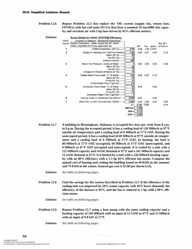
HVAC Simplified Solutions Manual
58
Problem 12.6 Repeat Problem 12.5 but replace the VAV system (supply fan, return fans,FPVAVs) with fan-coil units (FCUs) that have a nominal 10 ton/4000 cfm capac-ity and circulate air with 3 hp fans driven by 85% efficient motors.
Solution
Problem 12.7 A building in Birmingham, Alabama, is occupied five days per week from 8 a.m.to 8 p.m. During the occupied period, it has a cooling load of 120 MBtu/h at 97°Foutside air temperature and a cooling load of 0 MBtu/h at 57°F OAT. During theunoccupied period, it has a cooling load of 40 MBtu/h at 97°F outside air temper-ature and a cooling load of 0 MBtu/h at 57°F OAT. In heating, the load is80 MBtu/h at 17°F OAT (occupied), 60 MBtu/h at 17°F OAT (unoccupied), and0 MBtu/h at 47°F OAT (occupied and unoccupied). It is cooled by a unit with a125 MBtu/h capacity and 14 kW demand at 97°F and a 141 MBtu/h capacity and11.4 kW demand at 67°F. It is heated by a unit with a 120 MBtu/h heating capac-ity with an 80% efficiency with a 1.5 hp 82% efficient fan motor. Compute theannual cost of heating and cooling the building based on 8¢/kWh in the summerand 7¢/kWh in the winter. Natural gas cost is $1.80 per therm (ccf).
Solution See table on following pages.
Problem 12.8 Find the savings for the system described in Problem 12.7 if the efficiency of thecooling unit was improved by 20% (same capacity with 20% lower demand), theefficiency of the furnace is 95%, and the fan is reduced to 1 hp with a 90% effi-cient motor.
Solution See table on following pages.
Problem 12.9 Repeat Problem 12.7 using a heat pump with the same cooling capacity and aheating capacity of 120 MBtu/h with an input of 11.3 kW at 47°F and 55 MBtu/hwith an input of 9.8 kW at 17°F.
Solution See table on following pages.
Copyright ASHRAE Provided by IHS under license with ASHRAE Licensee=Kellogg Brown & Root Jakarta /3262700002, User=Rohana, Mumuh
Not for Resale, 09/09/2009 18:54:17 MDTNo reproduction or networking permitted without license from IHS
--`,,``,`,,,`,,`,````,`,`,,,,``,-`-`,,`,,`,`,,`---
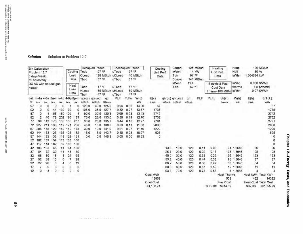
Chapte
r 12
—Energ
y, C
osts
, and E
conom
ics
59
Solution Solution to Problem 12.7:
Copyright A
SH
RA
E
Provided by IH
S under license w
ith AS
HR
AE
Licensee=
Kellogg B
rown &
Root Jakarta /3262700002, U
ser=R
ohana, Mum
uhN
ot for Resale, 09/09/2009 18:54:17 M
DT
No reproduction or netw
orking permitted w
ithout license from IH
S
--`,,``,`,,,`,,`,````,`,`,,,,``,-`-`,,`,,`,`,,`---
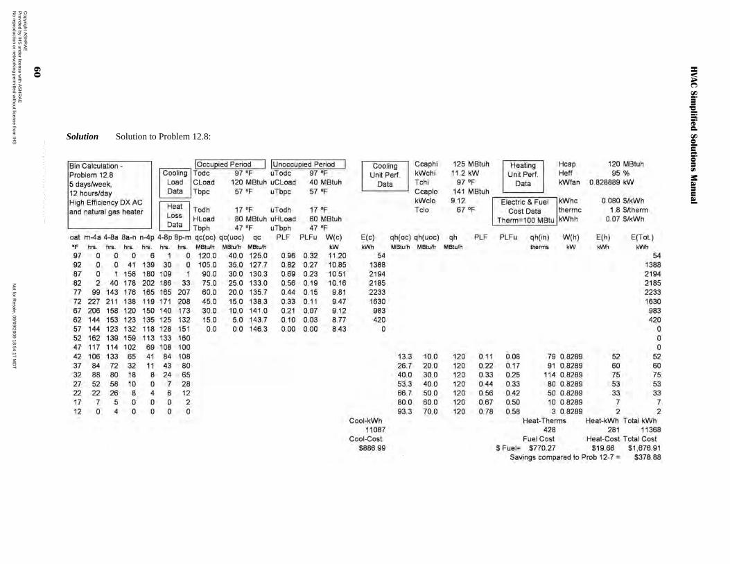
HVAC S
implifie
d S
olu
tions M
anual
60
Solution Solution to Problem 12.8:
Copyright A
SH
RA
E
Provided by IH
S under license w
ith AS
HR
AE
Licensee=
Kellogg B
rown &
Root Jakarta /3262700002, U
ser=R
ohana, Mum
uhN
ot for Resale, 09/09/2009 18:54:17 M
DT
No reproduction or netw
orking permitted w
ithout license from IH
S --`,,``,`,,,`,,`,````,`,`,,,,``,-`-`,,`,,`,`,,`---
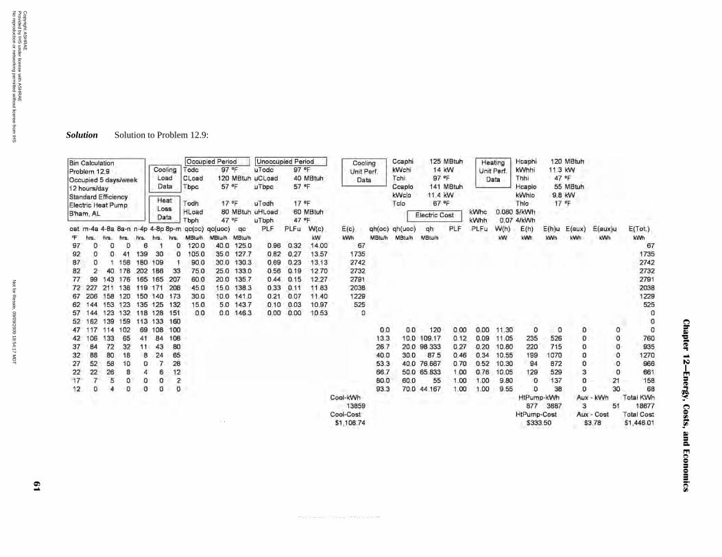
Chapte
r 12
—Energ
y, C
osts
, and E
conom
ics
61
Solution Solution to Problem 12.9:
Copyright A
SH
RA
E
Provided by IH
S under license w
ith AS
HR
AE
Licensee=
Kellogg B
rown &
Root Jakarta /3262700002, U
ser=R
ohana, Mum
uhN
ot for Resale, 09/09/2009 18:54:17 M
DT
No reproduction or netw
orking permitted w
ithout license from IH
S
--`,,``,`,,,`,,`,````,`,`,,,,``,-`-`,,`,,`,`,,`---

HVAC Simplified Solutions Manual
62
Problem 12.10 Discuss the economic value of installing a $10,000 energy efficiency package on a$225,000, 30-year, 6.25% APR home mortgage that will lower monthly utilitybills by $40. The energy inflation rate is expected to be 8%.
Solution
The added monthly mortgage payment is $62.17, but the savings is only $40 permonth. However, the cost of energy is inflating at a higher rate compared to inflationand the monthly note is fixed, so after 12 years the owner begins to receive a positivereturn if he/she plans on owning the home for this extended period and the life of theenergy efficiency package is more than 12 years. Given the frequency of moving to anew home for the typical US family, this would be a marginal investment.
Problem 12.11 Repeat Problem 12.10 for an energy inflation rate of 4%.
Solution When problem 12.10 is repeated with an energy inflation rate of 4% rather than 8%,the investment will require 27 years to receive a positive return. Even though themortgage payment is fixed, the energy inflation rate is low compared to inflation, sothe payback period is extended.
Added Cost Loan Interest Energy Inflation Main. Inflation Gen. Inflation
of ECO Rate (%) Rate (%) Rate (%) Rate -CPI (%)
10000 6.25 8 5 5
Year One Year One Added Annual Added Monthly
Energy Savings Maint. Cost* Payment ($) Payment ($)
480 0 746.03 62.17
Year Energy Savings Maint. Cost* Net Cash Flow Disc. NCF Pres. Worth
1 480.00 0.00 -266.03 -266.03 -266.03
2 518.40 0.00 -227.63 -216.79 -482.82
3 559.87 0.00 -186.16 -168.85 -651.67
4 604.66 0.00 -141.37 -122.12 -773.78
5 653.03 0.00 -92.99 -76.51 -850.29
6 705.28 0.00 -40.75 -31.93 -882.22
7 761.70 0.00 15.67 11.69 -870.53
8 822.64 0.00 76.61 54.44 -816.08
9 888.45 0.00 142.42 96.39 -719.69
10 959.52 0.00 213.49 137.62 -582.07
11 1036.28 0.00 290.26 178.19 -403.88
12 1119.19 0.00 373.16 218.18 -185.70
13 1208.72 0.00 462.69 257.64 71.95
14 1305.42 0.00 559.39 296.66 368.60
15 1409.85 0.00 663.82 335.28 703.88
16 1522.64 0.00 776.61 373.56 1077.44
17 1644.45 0.00 898.42 411.58 1489.02
18 1776.01 0.00 1029.98 449.38 1938.40
19 1918.09 0.00 1172.06 487.02 2425.42
20 2071.54 0.00 1325.51 524.55 2949.96
21 2237.26 0.00 1491.23 562.03 3511.99
22 2416.24 0.00 1670.21 599.51 4111.50
23 2609.54 0.00 1863.51 637.04 4748.54
24 2818.30 0.00 2072.27 674.67 5423.22
25 3043.77 0.00 2297.74 712.45 6135.67
26 3287.27 0.00 2541.24 750.44 6886.11
27 3550.25 0.00 2804.22 788.66 7674.77
28 3834.27 0.00 3088.24 827.18 8501.95
29 4141.01 0.00 3394.98 866.04 9367.99
30 4472.29 0.00 3726.26 905.28 10273.27
Economic Analysis Using 30-Year Fixed Rate Loan with Inflation
Copyright ASHRAE Provided by IHS under license with ASHRAE Licensee=Kellogg Brown & Root Jakarta /3262700002, User=Rohana, Mumuh
Not for Resale, 09/09/2009 18:54:17 MDTNo reproduction or networking permitted without license from IHS
--`,,``,`,,,`,,`,````,`,`,,,,``,-`-`,,`,,`,`,,`---
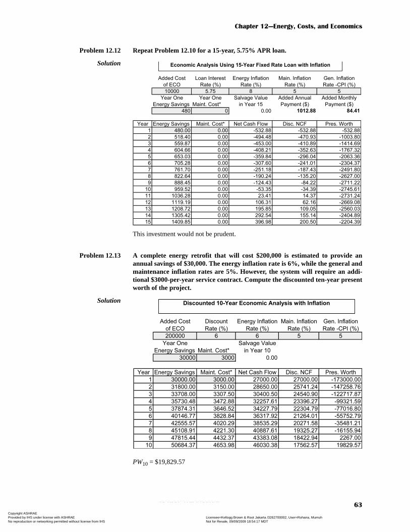
Chapter 12—Energy, Costs, and Economics
63
Problem 12.12 Repeat Problem 12.10 for a 15-year, 5.75% APR loan.
Solution
This investment would not be prudent.
Problem 12.13 A complete energy retrofit that will cost $200,000 is estimated to provide anannual savings of $30,000. The energy inflation rate is 6%, while the general andmaintenance inflation rates are 5%. However, the system will require an addi-tional $3000-per-year service contract. Compute the discounted ten-year presentworth of the project.
Solution
PW10 = $19,829.57
Added Cost Loan Interest Energy Inflation Main. Inflation Gen. Inflation
of ECO Rate (%) Rate (%) Rate (%) Rate -CPI (%)
10000 5.75 8 5 5
Year One Year One Salvage Value Added Annual Added Monthly
Energy Savings Maint. Cost* in Year 15 Payment ($) Payment ($)
480 0 0.00 1012.88 84.41
Year Energy Savings Maint. Cost* Net Cash Flow Disc. NCF Pres. Worth
1 480.00 0.00 -532.88 -532.88 -532.88
2 518.40 0.00 -494.48 -470.93 -1003.80
3 559.87 0.00 -453.00 -410.89 -1414.69
4 604.66 0.00 -408.21 -352.63 -1767.32
5 653.03 0.00 -359.84 -296.04 -2063.36
6 705.28 0.00 -307.60 -241.01 -2304.37
7 761.70 0.00 -251.18 -187.43 -2491.80
8 822.64 0.00 -190.24 -135.20 -2627.00
9 888.45 0.00 -124.43 -84.22 -2711.22
10 959.52 0.00 -53.35 -34.39 -2745.61
11 1036.28 0.00 23.41 14.37 -2731.24
12 1119.19 0.00 106.31 62.16 -2669.08
13 1208.72 0.00 195.85 109.05 -2560.03
14 1305.42 0.00 292.54 155.14 -2404.89
15 1409.85 0.00 396.98 200.50 -2204.39
Economic Analysis Using 15-Year Fixed Rate Loan with Inflation
Added Cost Discount Energy Inflation Main. Inflation Gen. Inflation
of ECO Rate (%) Rate (%) Rate (%) Rate -CPI (%)
200000 6 6 5 5
Year One Salvage Value
Energy Savings Maint. Cost* in Year 10
30000 3000 0.00
Year Energy Savings Maint. Cost* Net Cash Flow Disc. NCF Pres. Worth
1 30000.00 3000.00 27000.00 27000.00 -173000.00
2 31800.00 3150.00 28650.00 25741.24 -147258.76
3 33708.00 3307.50 30400.50 24540.90 -122717.87
4 35730.48 3472.88 32257.61 23396.27 -99321.59
5 37874.31 3646.52 34227.79 22304.79 -77016.80
6 40146.77 3828.84 36317.92 21264.01 -55752.79
7 42555.57 4020.29 38535.29 20271.58 -35481.21
8 45108.91 4221.30 40887.61 19325.27 -16155.94
9 47815.44 4432.37 43383.08 18422.94 2267.00
10 50684.37 4653.98 46030.38 17562.57 19829.57
Discounted 10-Year Economic Analysis with Inflation
Copyright ASHRAE Provided by IHS under license with ASHRAE Licensee=Kellogg Brown & Root Jakarta /3262700002, User=Rohana, Mumuh
Not for Resale, 09/09/2009 18:54:17 MDTNo reproduction or networking permitted without license from IHS
--`,,``,`,,,`,,`,````,`,`,,,,``,-`-`,,`,,`,`,,`---

HVAC Simplified Solutions Manual
64
Problem 12.14 Calculate the discounted rate of return on the project described inProblem 12.13 for a ten-year evaluation.
Solution
RR10 = 8.5276% (discount rate that results in PW10 = $0)
Added Cost Discount Energy Inflation Main. Inflation Gen. Inflation
of ECO Rate (%) Rate (%) Rate (%) Rate -CPI (%)
200000 8.5276 6 5 5
Year One Salvage Value
Energy Savings Maint. Cost* in Year 10
30000 3000 0.00
Year Energy Savings Maint. Cost* Net Cash Flow Disc. NCF Pres. Worth
1 30000.00 3000.00 27000.00 27000.00 -173000.00
2 31800.00 3150.00 28650.00 25141.73 -147858.27
3 33708.00 3307.50 30400.50 23411.10 -124447.18
4 35730.48 3472.88 32257.61 21799.35 -102647.82
5 37874.31 3646.52 34227.79 20298.36 -82349.47
6 40146.77 3828.84 36317.92 18900.51 -63448.96
7 42555.57 4020.29 38535.29 17598.74 -45850.22
8 45108.91 4221.30 40887.61 16386.46 -29463.75
9 47815.44 4432.37 43383.08 15257.53 -14206.22
10 50684.37 4653.98 46030.38 14206.24 0.02
Discounted 10-Year Economic Analysis with Inflation
Copyright ASHRAE Provided by IHS under license with ASHRAE Licensee=Kellogg Brown & Root Jakarta /3262700002, User=Rohana, Mumuh
Not for Resale, 09/09/2009 18:54:17 MDTNo reproduction or networking permitted without license from IHS
--`,,``,`,,,`,,`,````,`,`,,,,``,-`-`,,`,,`,`,,`---
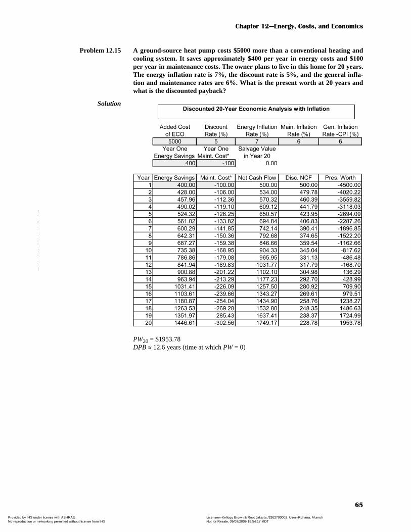
Chapter 12—Energy, Costs, and Economics
65
Problem 12.15 A ground-source heat pump costs $5000 more than a conventional heating andcooling system. It saves approximately $400 per year in energy costs and $100per year in maintenance costs. The owner plans to live in this home for 20 years.The energy inflation rate is 7%, the discount rate is 5%, and the general infla-tion and maintenance rates are 6%. What is the present worth at 20 years andwhat is the discounted payback?
Solution
PW20 = $1953.78DPB ≈ 12.6 years (time at which PW = 0)
Added Cost Discount Energy Inflation Main. Inflation Gen. Inflation
of ECO Rate (%) Rate (%) Rate (%) Rate -CPI (%)
5000 5 7 6 6
Year One Year One Salvage Value
Energy Savings Maint. Cost* in Year 20
400 -100 0.00
Year Energy Savings Maint. Cost* Net Cash Flow Disc. NCF Pres. Worth
1 400.00 -100.00 500.00 500.00 -4500.00
2 428.00 -106.00 534.00 479.78 -4020.22
3 457.96 -112.36 570.32 460.39 -3559.82
4 490.02 -119.10 609.12 441.79 -3118.03
5 524.32 -126.25 650.57 423.95 -2694.09
6 561.02 -133.82 694.84 406.83 -2287.26
7 600.29 -141.85 742.14 390.41 -1896.85
8 642.31 -150.36 792.68 374.65 -1522.20
9 687.27 -159.38 846.66 359.54 -1162.66
10 735.38 -168.95 904.33 345.04 -817.62
11 786.86 -179.08 965.95 331.13 -486.48
12 841.94 -189.83 1031.77 317.79 -168.70
13 900.88 -201.22 1102.10 304.98 136.29
14 963.94 -213.29 1177.23 292.70 428.99
15 1031.41 -226.09 1257.50 280.92 709.90
16 1103.61 -239.66 1343.27 269.61 979.51
17 1180.87 -254.04 1434.90 258.76 1238.27
18 1263.53 -269.28 1532.80 248.35 1486.63
19 1351.97 -285.43 1637.41 238.37 1724.99
20 1446.61 -302.56 1749.17 228.78 1953.78
Discounted 20-Year Economic Analysis with Inflation
Copyright ASHRAE Provided by IHS under license with ASHRAE Licensee=Kellogg Brown & Root Jakarta /3262700002, User=Rohana, Mumuh
Not for Resale, 09/09/2009 18:54:17 MDTNo reproduction or networking permitted without license from IHS
--`,,``,`,,,`,,`,````,`,`,,,,``,-`-`,,`,,`,`,,`---

HVAC Simplified Solutions Manual
66
Problem 12.16 Repeat Problem 12.15 for ie = 6%, ig = im = 7%, and d = 6% and compare theseresults with a simple payback analysis.
Solution
PW20 = $750.05DPB ≈ 16.3 years (time at which PW = 0)SPB = $5000 ÷ [$400/yr – (–$100/yr)] = 10 years
Added Cost Discount Energy Inflation Main. Inflation Gen. Inflation
of ECO Rate (%) Rate (%) Rate (%) Rate -CPI (%)
5000 6 6 7 7
Year One Year One Salvage Value
Energy Savings Maint. Cost* in Year 20
400 -100 0.00
Year Energy Savings Maint. Cost* Net Cash Flow Disc. NCF Pres. Worth
1 400.00 -100.00 500.00 500.00 -4500.00
2 424.00 -107.00 531.00 468.17 -4031.83
3 449.44 -114.49 563.93 438.38 -3593.45
4 476.41 -122.50 598.91 410.48 -3182.97
5 504.99 -131.08 636.07 384.37 -2798.60
6 535.29 -140.26 675.55 359.92 -2438.68
7 567.41 -150.07 717.48 337.03 -2101.65
8 601.45 -160.58 762.03 315.61 -1786.05
9 637.54 -171.82 809.36 295.54 -1490.50
10 675.79 -183.85 859.64 276.76 -1213.74
11 716.34 -196.72 913.05 259.18 -954.56
12 759.32 -210.49 969.80 242.72 -711.84
13 804.88 -225.22 1030.10 227.30 -484.54
14 853.17 -240.98 1094.16 212.87 -271.67
15 904.36 -257.85 1162.21 199.36 -72.31
16 958.62 -275.90 1234.53 186.70 114.39
17 1016.14 -295.22 1311.36 174.86 289.25
18 1077.11 -315.88 1392.99 163.77 453.02
19 1141.74 -337.99 1479.73 153.38 606.40
20 1210.24 -361.65 1571.89 143.65 750.05
Discounted 20-Year Economic Analysis with Inflation
Copyright ASHRAE Provided by IHS under license with ASHRAE Licensee=Kellogg Brown & Root Jakarta /3262700002, User=Rohana, Mumuh
Not for Resale, 09/09/2009 18:54:17 MDTNo reproduction or networking permitted without license from IHS
--`,,``,`,,,`,,`,````,`,`,,,,``,-`-`,,`,,`,`,,`---

Copyright ASHRAE Provided by IHS under license with ASHRAE Licensee=Kellogg Brown & Root Jakarta /3262700002, User=Rohana, Mumuh
Not for Resale, 09/09/2009 18:54:17 MDTNo reproduction or networking permitted without license from IHS
--`,,``,`,,,`,,`,````,`,`,,,,``,-`-`,,`,,`,`,,`---