Embed Size (px)
Citation preview
OPERATING MANUAL
MULTIPLE OUTPUT LINEAR SYSTEM DC POWER SUPPLIES
Agilent MODELS 6621A, 6622A, 6623A, 6624A, and 6627A
Agilent Part No 5957-6377
Microfiche Part No. 5957-6378 Printed in Malaysia September, 2004
2
CERTIFICATION Agilent Technologies certifies that this product met its published specifications at time of shipment from the factory. Agilent Technologies further certifies that its calibration measurements are traceable to the United States National Bureau of Standards, to the extent allowed by the Bureau's calibration facility, and to the calibration facilities of other International Standards Organization members.
WARRANTY This Agilent Technologies hardware product is warranted against defects in material and workmanship for a period of one year from date of delivery. Agilent software and firmware products, which are designated by Agilent for use with a hardware product and when properly installed on that hardware product, are warranted not to fail to execute their programming instructions due to defects in material and workmanship for a period of 90 days from date of delivery. During the warranty period Agilent Technologies will, at its option, either repair or replace products which prove to be defective. Agilent does not warrant that the operation for the software, firmware, or hardware shall be uninterrupted or error free. For warranty service, with the exception of warranty options, this product must be returned to a service facility designated by Agilent. Customer shall prepay shipping charges by (and shall pay all duty and taxes) for products returned to Agilent for warranty service. Except for products returned to Customer from another country, Agilent shall pay for return of products to Customer. Warranty services outside the country of initial purchase are included in Agilent's product price, only if Customer pays Agilent international prices (defined as destination local currency price, or U.S. or Geneva Export price). If Agilent is unable, within a reasonable time to repair or replace any product to condition as warranted, the Customer shall be entitled to a refund of the purchase price upon return of the product to Agilent.
LIMITATION OF WARRANTY The foregoing warranty shall not apply to defects resulting from improper or inadequate maintenance by the Customer, Customer-supplied software or interfacing, unauthorized modification or misuse, operation outside of the environmental specifications for the product, or improper site preparation and maintenance. NO OTHER WARRANTY IS EXPRESSED OR IMPLIED. AGILENT SPECIFICALLY DISCLAIMS THE IMPLIED WARRANTIES OF MERCHANTABILITY AND FITNESS FOR A PARTICULAR PURPOSE.
EXCLUSIVE REMEDIES THE REMEDIES PROVIDED HEREIN ARE THE CUSTOMER'S SOLE AND EXCLUSIVE REMEDIES. AGILENT SHALL NOT BE LIABLE FOR ANY DIRECT, INDIRECT, SPECIAL, INCIDENTAL, OR CONSEQUENTIAL DAMAGES, WHETHER BASED ON CONTRACT, TORT, OR ANY OTHER LEGAL THEORY.
ASSISTANCE The above statements apply only to the standard product warranty. Warranty options, extended support contracts, product maintenance agreements and customer assistance agreements are also available. Contact your nearest Agilent Technologies Sales and Service office for further information on Agilent's full line of Support Programs.
Copyright 2000, 2004 Agilent Technologies Edition 1___January, 1993 Update 1___February, 2000
Update 2___September, 2004
3
SAFETY SUMMARYThe following general safety precautions must be observed during all phases of operation, service, and repair of thisinstrument. Failure to comply with these precautions or with specific warnings elsewhere in this manual violates safetystandards of design, manufacture, and intended use of the instrument. Agilent Technologies assumes no liability for thecustomer’s failure to comply with these requirements.
BEFORE APPLYING POWER.Verify that the product is set to match the available line voltage and the correct fuse is installed.
GROUND THE INSTRUMENT.This product is a Safety Class 1 instrument (provided with a protective earth terminal). To minimize shock hazard, the instrument chassisand cabinet must be connected to an electrical ground. The instrument must be connected to the ac power supply mains through a three-conductor power cable, with the third wire firmly connected to an electrical ground (safety ground) at the power outlet. For instrumentsdesigned to be hard-wired to the ac power lines (supply mains), connect the protective earth terminal to a protective conductor before anyother connection is made. Any interruption of the protective (grounding) conductor or disconnection of the protective earth terminal willcause a potential shock hazard that could result in personal injury. If the instrument is to be energized via an external autotransformer forvoltage reduction, be certain that the autotransformer common terminal is connected to the neutral (earthed pole) of the ac power lines(supply mains).
FUSES.Only fuses with the required rated current, voltage, and specified type (normal blow, time delay, etc.) should be used. Do not use repairedfuses or short circuited fuseholders. To do so could cause a shock or fire hazard.
DO NOT OPERATE IN AN EXPLOSIVE ATMOSPHERE.Do not operate the instrument in the presence of flammable gases or fumes.
KEEP AWAY FROM LIVE CIRCUITS.Operating personnel must not remove instrument covers. Component replacement and internal adjustments must be made by qualifiedservice personnel. Do not replace components with power cable connected. Under certain conditions, dangerous voltages may exist evenwith the power cable removed. To avoid injuries, always disconnect power, discharge circuits and remove external voltage sources beforetouching components.
DO NOT SERVICE OR ADJUST ALONE.Do not attempt internal service or adjustment unless another person, capable of rendering first aid and resuscitation, is present.
DO NOT EXCEED INPUT RATINGS.This instrument may be equipped with a line filter to reduce electromagnetic interference and must be connected to a properly groundedreceptacle to minimize electric shock hazard. Operation at line voltages or frequencies in excess of those stated on the data plate maycause leakage currents in excess of 5.0 mA peak.
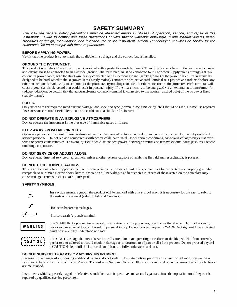
SAFETY SYMBOLS.
Instruction manual symbol: the product will be marked with this symbol when it is necessary for the user to refer to the instruction manual (refer to Table of Contents) .
Indicates hazardous voltages.
Indicate earth (ground) terminal.
The WARNING sign denotes a hazard. It calls attention to a procedure, practice, or the like, which, if not correctlyperformed or adhered to, could result in personal injury. Do not proceed beyond a WARNING sign until the indicatedconditions are fully understood and met.
The CAUTION sign denotes a hazard. It calls attention to an operating procedure, or the like, which, if not correctlyperformed or adhered to, could result in damage to or destruction of part or all of the product. Do not proceed beyonda CAUTION sign until the indicated conditions are fully understood and met.
DO NOT SUBSTITUTE PARTS OR MODIFY INSTRUMENT.Because of the danger of introducing additional hazards, do not install substitute parts or perform any unauthorized modification to theinstrument. Return the instrument to an Agilent Technologies Sales and Service Office for service and repair to ensure that safety featuresare maintained.
Instruments which appear damaged or defective should be made inoperative and secured against unintended operation until they can berepaired by qualified service personnel.
4
SAFETY SUMMARY (continued)
GENERALAny LEDs used in this product are Class 1 LEDs as per IEC 825-1.
ENVIRONMENTAL CONDITIONSThis instrument is intended for indoor use in an installation category II, pollution degree 2 environment. It is designed tooperate at a maximum relative humidity of 95% and at altitudes of up to 2000 meters. Refer to the specifications tables for theac mains voltage requirements and ambient operating temperature range.
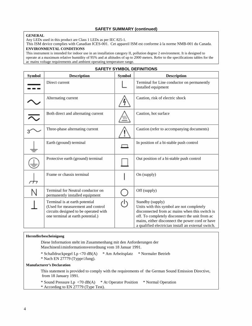
SAFETY SYMBOL DEFINITIONS
Symbol Description Symbol Description
Direct current Terminal for Line conductor on permanentlyinstalled equipment
Alternating current Caution, risk of electric shock
Both direct and alternating current Caution, hot surface
Three-phase alternating current Caution (refer to accompanying documents)
Earth (ground) terminal In position of a bi-stable push control
Protective earth (ground) terminal Out position of a bi-stable push control
Frame or chassis terminal On (supply)
Terminal for Neutral conductor onpermanently installed equipment
Off (supply)
Terminal is at earth potential(Used for measurement and controlcircuits designed to be operated withone terminal at earth potential.)
Standby (supply)Units with this symbol are not completelydisconnected from ac mains when this switch isoff. To completely disconnect the unit from acmains, either disconnect the power cord or havea qualified electrician install an external switch.
Herstellerbescheinigung
Diese Information steht im Zusammenhang mit den Anforderungen derMaschinenläminformationsverordnung vom 18 Januar 1991.
* Schalldruckpegel Lp <70 dB(A) * Am Arbeitsplatz * Normaler Betrieb* Nach EN 27779 (Typprüfung).
Manufacturer’s Declaration
This statement is provided to comply with the requirements of the German Sound Emission Directive, from 18 January 1991.
* Sound Pressure Lp <70 dB(A) * At Operator Position * Normal Operation* According to EN 27779 (Type Test).
This ISM device complies with Canadian ICES-001. Cet appareil ISM est conforme à la norme NMB-001 du Canada.
5
DECLARATION OF CONFORMITY According to ISO/IEC Guide 22 and CEN/CENELEC EN 45014
Manufacturer’s Name and Address Responsible Party Alternate Manufacturing Site Agilent Technologies, Inc. Agilent Technologies (Malaysia) Sdn. Bhd 550 Clark Drive, Suite 101 Budd Lake, New Jersey 07828 USA
Malaysia Manufacturing Bayan Lepas Free Industrial Zone, PH III 11900 Penang,
Malaysia Declares under sole responsibility that the product as originally delivered Product Names a) Multiple Output 40 W and 80 W system dc Power Supplies
b) Multiple Output 25 W and 50 W precision system dc Power Supplies Model Numbers a) 6621A, 6622A, 6623A; 6624A, 6627A
b) 6625A; 6626A; 6628A; 6629A (and other customized products based upon the above)
Product Options This declaration covers all options and customized products based on the above products.
Complies with the essential requirements of the Low Voltage Directive 73/23/EEC and the EMC Directive 89/336/EEC (including 93/68/EEC) and carries the CE Marking accordingly.
EMC Information ISM Group 1 Class A Emissions
As detailed in Electromagnetic Compatibility (EMC), Certificate of Conformance Number CC/TCF/00/076 based on Technical Construction File (TCF) HPNJ3, dated Oct. 29, 1997
Assessed by: Celestica Ltd, Appointed Competent Body
Westfields House, West Avenue Kidsgrove, Stoke-on-Trent Straffordshire, ST7 1TL United Kingdom
Safety Information and Conforms to the following safety standards.
IEC 61010-1:2001 / EN 61010-1:2001 UL 1244 CSA C22.2 No. 1010.1:1992
This DoC applies to the above-listed products placed on the EU market after:
January 1, 2004
Date Bill Darcy/ Regulations Manager For further information, please contact your local Agilent Technologies sales office, agent or distributor. Authorized EU-representative: Agilent Technologies Deutschland GmbH, Herrenberger Straβe 130, D 71034 Böblingen, Germany Revision: B.00.00 Issue Date: Created on 11/24/2003 3:33
PM Document No. 662xA.11.24.doc
To obtain the latest Declaration of Conformity, go to http://regulations.corporate.agilent.com and click on “Declarations of Conformity.”
6
WHAT THIS MANUAL CONTAINS
This is the Operating manual for the Agilent 6621A through 6624A and 6627A Series of Multiple Output Linear SystemPower Supplies. It contains information relating to the installation, operation, and programming of these supplies asoutlined below. Maintenance and troubleshooting instructions are given in a separate Service Manual (Agilent Part No.5957-6379).
Chapter 1.--General InformationChapter 1 contains a general description of the power supplies as well as instrument specifications and informationconcerning options and accessories.
Chapter 2.--Installation ProceduresChapter 2 contains information to prepare the supply for use. Included in this chapter are power requirements, line voltageconversion, and GP-IB interface connections.
Chapter 3.--Getting StartedChapter 3 contains a brief description of the supply’s front panel controls and indicators and describes how to turn on thesupply and to check it’s operation. An introduction to remote operation over the GP-IB is also given to help a first time userget started quickly.
Chapter 4.--Output Connections and Operating InformationChapter 4 contains information about making connections to the supply’s output terminals. General operating information isalso provided.
Chapter 5.--Remote OperationChapter 5 contains all of the information required to operate the supply remotely via a GP-IB computer. All of thecommands that can be used to program the supplies are described.
Chapter 6.--Local OperationChapter 6 contains instructions on using all of the front panel controls and indicators.
Appendix A--Calibration ProcedureAppendix A contains programming steps and procedures that are required to calibrate your power supply. It isrecommended that the power supply be calibrated yearly.
Appendix B--Programming with Series 200 ComputerAppendix B contains Series 200/300 Computer programming examples (in Agilent extended BASIC language) for yourPower Supply’s most frequently used functions.
Appendix C--Command SummaryAppendix C contains an alphabetical listing of all commands that can be sent to a supply.
Appendix D--Error MessagesAppendix D contains a listing and brief explanation of all error codes and messages for all programming and hardwareerrors.
Appendix E - Manual BackdatingAppendix E contains backdating information for units with Serial numbers lower than those listed on the title page.
7
Table Of Contents
1 General InformationIntroduction............................ .......................................................................................................................11Safety Considerations....................................................................................................................................11Instrument and Manual Identification.... .......................................................................................................11Options................................. .........................................................................................................................11Accessories............................. .......................................................................................................................12Description ............................ .......................................................................................................................12Basic Operation......................... ....................................................................................................................13 GP-IB Board..............................................................................................................................................13 Output Boards............................................................................................................................................14Specifications......................... .......................................................................................................................15 Qualifying Conditions.................. .............................................................................................................15 Definitions............................ .....................................................................................................................15
2 InstallationIntroduction............................ .......................................................................................................................25Initial Inspection............................................................................................................................................25Location and Cooling.................... ................................................................................................................25Input Power Requirements................ ............................................................................................................26Line Fuse............................... ........................................................................................................................26Power Cord....................................................................................................................................................28Line Voltage Conversion...............................................................................................................................28GP-IB Interface Connector............................................................................................................................29
3 Getting StartedIntroduction ........................... .......................................................................................................................31Front Panel Controls and Indicators..... .........................................................................................................31Turning On Your Supply...............................................................................................................................31 Normal Self Test Indications.....................................................................................................................35 Self Test Errors..........................................................................................................................................36Checking Out Your Supply Using Local Control..........................................................................................36 Voltage Test............................ ..................................................................................................................37 Overvoltage Test......................... ..............................................................................................................37 Current Test............................ ...................................................................................................................37Introduction To Remote Operation....... ........................................................................................................38 Enter/Output Statements............................................................................................................................38 Reading the GP-IB Address.............. ........................................................................................................39 Changing the GP-IB Address............. .......................................................................................................39 Sending a Remote Command............... .....................................................................................................39 Getting Data from the Supply....................................................................................................................40 Often Used Commands..............................................................................................................................40 Returning the Supply to Local Mode..... ...................................................................................................42
4 Output Connections and Operating InformationIntroduction ............................... ...................................................................................................................43Output Ranges............................... ................................................................................................................43 Operating Quadrants..................................................................................................................................44 Range Selection............................. ............................................................................................................44Protection Features......................... ...............................................................................................................44Connecting The Load......................... ...........................................................................................................46 Wire Size Selection......................... ..........................................................................................................47 Multiple Loads.............................. ............................................................................................................49
8
Table Of Contents (continued)
Positive and Negative Voltages.................................................................................................................49Remote Voltage Sensing..................... ..........................................................................................................49 Remote Sense Connections................... ....................................................................................................50 Output Noise Considerations.....................................................................................................................51 Programming Response Time with an Output Capacitor............................. .............................................51 Open Sense Leads......................................................................................................................................51Overvoltage Trigger Connections............ .....................................................................................................52 External Trigger Circuit................... .........................................................................................................52Power Supply Protection Considerations .......................... ...........................................................................54 Battery Charging........................... ............................................................................................................54 Capacitive Load Limitation........... ............................................................................................................54Parallel Operation..........................................................................................................................................54 CV Operation............................... .............................................................................................................55 CC Operation.............................................................................................................................................56 Remote Sensing........................... ..............................................................................................................56 Specifications for Parallel Operation.........................................................................................................56Series Operation....................... .....................................................................................................................57 CV Operation............................... .............................................................................................................57 CC Operation.............................................................................................................................................58 Remote Sensing........................... ..............................................................................................................58 Specifications for Series Operation. ..........................................................................................................58
5 Remote OperationIntroduction ............................. .....................................................................................................................61GP-IB Operation............................................................................................................................................61 Interface Function......................................................................................................................................61 GP-IB Address Selection...........................................................................................................................62 Power-On Service Request (PON) ............................................................................................................63Programming Syntax......................... ............................................................................................................63 Numeric Data............................... .............................................................................................................63 Order of Execution......................... ...........................................................................................................68 Terminators................................ ...............................................................................................................68Initial Conditions...........................................................................................................................................68Power Supply Commands .............................................................................................................................68 Voltage Programming........................ .......................................................................................................69 Current Programming.............................. ..................................................................................................69 Range Switching........................................................................................................................................70 Output On/Off.................................... .......................................................................................................71 Overvoltage Protection........................... ...................................................................................................71 Overcurrent Protection........................... ...................................................................................................72 Multiple Output Storage and Recall............... ...........................................................................................72 The Clear Command..................................................................................................................................73 Status Reporting................................. .......................................................................................................73 Service Request Generation....................... ...............................................................................................76 Reprogramming Delay............................. .................................................................................................78 Display On/Off................................... .......................................................................................................78 Other Queries.............................................................................................................................................79
6 Local OperationIntroduction ..................................... .............................................................................................................83Local Mode....................................................................................................................................................83Local Control Of Output Functions...............................................................................................................83General........................................... ...............................................................................................................83

9
Table Of Contents (continued) Setting Voltage................................. ......................................................................................................... 84 Setting Current................................... ....................................................................................................... 84 Enabling/Disabling an Output...................... ............................................................................................. 85 Setting Overvoltage Protection.................... ............................................................................................. 85 Resetting Overvoltage Protection.............................................................................................................. 85 Enabling/Disabling Overcurrent Protection........ ...................................................................................... 85 Resetting Overcurrent Protection................. ............................................................................................. 85 Displaying the Contents of the Fault Register........................................................................................... 85 Setting the Reprogramming Delay................ ............................................................................................ 86 Local Control Of System Functions................ .............................................................................................. 86 Setting the Supply's GP-IB Address.......................................................................................................... 86 Displaying Error Messages....................... ................................................................................................ 87 Storing and Recalling Voltage and Current Settings for all Outputs......................................................... 87
A Calibration
Introduction...................................... ............................................................................................................. 89 Test Equipment and Setup Required................. ............................................................................................ 89 General Calibration Procedure..................... ................................................................................................. 91 Calibration Program.............................. ........................................................................................................ 93
B Programming With a Series 200/300 Computer
Introduction ....................... ........................................................................................................................... 97 I/O Path Names...................... ....................................................................................................................... 97 Voltage and Current Programming..... .......................................................................................................... 97 Voltage and Current Programming With Variables... ................................................................................... 98 Voltage and Current Readback........ ............................................................................................................. 98 Programming Power Supply Registers.. ....................................................................................................... 99 Present Status...................... ...................................................................................................................... 99 Service Request and Serial Poll..... ........................................................................................................... 99 Error Detection ....................................................................................................................................... 101 Stored Operating States........................................................................................................................... 102 Programming Outputs Connected In Parallel.............................................................................................. 102 CC Operation....................... ................................................................................................................... 103 CV Operation....................... ................................................................................................................... 103 Programming Outputs Connected In Series..... ........................................................................................... 104
C Command Summary Introduction................................................................................................................................................. 105 D Error Messages
Introduction....................... .......................................................................................................................... 109 Power-On Self Test Messages..................................................................................................................... 109 Error Responses..................... ..................................................................................................................... 109 Test Responses...................... ...................................................................................................................... 109
E Manual Backdating Introduction ........................ ........................................................................................................................ 113 Make Changes ....................... ..................................................................................................................... 113 Agilent Sales and Support Office Contacts ...................................................................................................................................................... 114

General Information 11
1General Information
Introduction
This chapter contains a general description of your power supply, as well as its performance specifications. Informationabout options, accessories, and GP-IB cables is also provided. This manual describes all five models in the Agilent 6621A-6624A, and 6627A power supply family. Unless stated otherwise, the information in this manual applies to all of thesemodels. Information that is specific to one model only is identified as such in this manual.
Safety Considerations
This product is a Safety Class 1 instrument, which means that it is provided with a protective earth terminal. This terminalmust be connected to a power source that has a 3-wire ground receptacle. Review the instrument and this manual for safetymarkings and instructions before operation. Refer to the Safety Summary page at the beginning of this manual for asummary of general safety information. Safety information for specific procedures is located at appropriate places in thismanual.
Instrument and Manual Identification
Agilent Technologies power supplies are identified by a two-part serial number, i.e. 2601A-00101. The first part of theserial number (the prefix) is a number/letter combination that denotes either the date of manufacture or the date of asignificant design change. It also indicates the country of origin. (Starting at 1960, 26 = 1986; 01 = the first week of theyear; A = U.S.A.) The second part of the serial number is a different sequential number assigned to each instrument startingwith 00101.
Options
Options 100,120, 220, and 240 simply determine which line voltage is selected at the factory. For information aboutchanging the line voltage setting, see Line Voltage Conversion, page 28.
Option 750 consists of a fault indicator (FLT) and remote inhibit (INH) circuit and relay control, which provide additionalshutdown protection should either the GP-IB and/or controller fail. This Option is described in a separate documententitled, "Appendix E Option 750 Operating Instructions for the Multiple Output Linear System DC Power Supply, AgilentModels 6621A, 6622A, 6623A, 6624A, and 6627A (Agilent P/N 5957-6372).
#100 Input power, 100 Vac, 47--66 Hz#120 Input power, 120 Vac, 47--66 Hz#220 Input power, 220 Vac, 47--66 Hz
#700 Computer Interface Intermediate Language (CIIL)#750 Fault (FLT) Remote Inhibit (INH) and Relay Control#908 One rack mount kit (5062-3977)#909 One rack mount kit with handles (5062-3983)#0L2 One extra operating manual
#240 Input power, 240 Vac, 47--66 Hz
#0B3 One service manual
General Information12
Accessories
10833A GP-IB cable, 1 m (3.3 ft)10833B GP-IB cable, 2 m (6.6 ft)10833C GP-IB cable, 4 m (13.2 ft)10833D GP-IB cable, 0.5 m (1.6 ft)10834A GP-IB connector extenderSlide mount kit (1494-0059)
Description
The Agilent 6621A-6624A, and 6627A Multiple Output Linear Power Supplies feature a combination of programmingcapabilities and linear power supply performance that make systems applications. The five models in this family offer atotal of up to 200 watts of output power, with voltages up to 50 volts and currents up to 10 amps. The output combinationsthat correspond to each model are shown in Table 1-1. Each isolated output can supply power in two ranges as shown inFigure 1-1. This flexibility allows you to use the same output to power loads with different voltage and currentrequirements. No separate command is required to program ranges; the power supply automatically selects one of theoperating ranges based on the last parameter (voltage or current) that is set. Additionally, each output contains an activedownprogrammer, which means that voltage downprogramming can be accomplished as quickly as upprogramming, evenwithout a load.
Table 1-1. Output Combinations AvailableModel Output 1 Output 2 Output 3 Output 4
Agilent 6621A 80 W Low Voltage 80 W Low Voltage - -Agilent 6622A 80 W High Voltage 80 W High Voltage - -Agilent 6623A 40 W Low Voltage 80 W Low Voltage 40 W High Voltage -Agilent 6624A 40 W Low Voltage 40 W Low Voltage 40 W High Voltage 40 W High VoltageAgilent 6627A 40 W High Voltage 40 W High Voltage 40 W High Voltage 40 W High Voltage
The output voltage and current for any output can be monitored with the front panel display. Output specific error messagesare also displayed. Front panel annunciators show the operating status of the instrument. The front panel keypad lets you setand readback the voltage limit, current limit, and overvoltage trip level of any output. With the keypad, you can also enableor disable outputs, mask and delay bits in the fault register, enable overcurrent protection, reset overvoltage and overcurrentprotection, and return to local operating mode.
Your multiple output power supply can be both a listener and a talker on the GP-IB. (GP-IB is Agilent Technologies’simplementation of IEEE-488). The built-in interface is tailored to the supply, resulting in simpler programming. Voltageand current settings can be sent directly to the specified dual range output in volts and amps.
Service can be requested from your power supply for up to ten reasons. The supply responds to a serial poll by identifyingthe output on which the fault occurred. Self-contained measurement and readback capability eliminate the need forexternally scanning the outputs using a separate DVM. Upon command the supply will measure its output voltage orcurrent and return the value on the GP-IB. The following functions are implemented via the GP-IB:
Voltage and current programming.Voltage and current measurement and readback.Present and accumulated status readback.Programmable service request mask.Programmable overvoltage and overcurrent protection.Storage and recall of programmed voltage and current values for all outputs.Queries of programmed functions or settings.Output enable or disable.Programming syntax error detection.

General Information 13
Programmable delay time for service request and OCP mask.Voltage, current, and overvoltage calibration.GP-IB interface selftest.Message display capability on the front panel.
Output connections are made to rear panel screw terminals. Either the positive or negative output terminal can be grounded,or the output can be floated up to ± 240 Vdc (including output voltage) from chassis ground. Output voltage can be locallyor remotely sensed, and identical outputs can be operated in series or parallel combinations for increased output voltage orcurrent capability. As shipped from the factory, the power supply is jumpered for local sensing.
Your power supply can be calibrated without having to remove the cover or even having to remove it from your systemcabinet. This feature allows you to calibrate the supply at its normal operating temperature. The recommended calibrationinterval is one year. Refer to Appendix A of this manual for complete calibration details. A calibration security jumper isavailable inside the unit. Access is described in the service manual.
Basic Operation
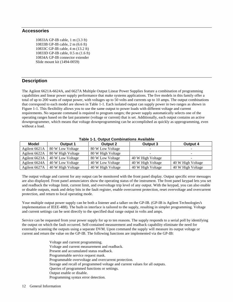
Figure 1-2 is a block diagram that illustrates the major assemblies contained within the power supply. As shown in thefigure, each supply includes a power transformer, two or more output boards, a GP-IB board, and front panel (display andcontrol keys).
Output Low Range Values High Range Values80 W Low, Voltage 7 V @ 10 A 20 V @ 4 A80 W High Voltage 20 V @ 4 A 50 V @ 2 A40 W Low Voltage 7 V @ 5 A 20 V @ 2 A40 W High Voltage 20 V @ 2 A 50 V @ 0.8 A
Figure 1-1. Output Operating Ranges for Agilent Models 6621A, 6624A and 6627A.
The appropriate ac input voltage is applied to each output board where it is converted to a raw dc voltage which issubsequently linearly regulated to become the dc output voltage. The magnitude of the output and the mode of operation aredetermined by the load and the data received from the GP-IB computer or from the front panel.
Each power supply model contains one output board for each output that it provides. Models 6624A and 6627A containfour 40 watt output boards; Model 6623A contains two 40 watt output boards and one 80 watt output board; Models 6621Aand 6622A each contain two 80 watt output boards.
GP-IB Board
The GP-IB board provides the interface between the user and the multiple outputs of the power supply. Each output boardis actually an output channel that can be individually selected and controlled over the GP-IB or from the supply’s frontpanel. Circuits on the GP-IB board interpret commands from the GP-IB or from the front panel to control the selectedoutput.
The GP-IB board also processes measurement and status data received from the output boards. This data may be read backover the GP-IB and/or displayed on the supply’s front panel.
General Information14
The power supply has no potentiometers. Each output is individually calibrated over the GP-IB using calibration commands(see Appendix A). Correction factors are calculated by the power supply during calibration and are stored in a non-volatilememory which is located on the supply’s GP-IB board. The supply contains no batteries.
Output Boards
The output boards are linear dc power supplies. Each isolated output has the L-shaped operating curve described inDescription, page 12 and Figure 1-1.
The ac input to each output board is rectified and applied to a regulator circuit. Each output board employs series regulationtechniques. A regulator element is connected in series with the load and operates in the linear region (between saturationand cutoff) of the transistor characteristic curve. Regulation is achieved by varying the conduction of the series element inresponse to a change in line voltage or circuit load.
The output board receives digital signals from the GP-IB board and converts them to analog signals which program theoutput voltage, current, and overvoltage values. The output may be programmed remotely over the GP-IB using commands(see Chapter 5) or locally from the supply’s front panel using the control keys (see Chapter 6).
The output board can be commanded to send measurement and status data back over the GP-IB and/or front panel. The datais sent back via the supply’s GP-IB board. GP-IB readback capabilities include output voltage and current, present andaccumulated status, and all programmed settings. The front panel LCD display can indicate the output voltage and current,the supply’s GP-IB address, error messages, and programmed values. Annunciators on the front panel indicate the operatingstatus of the selected channel (output board).
Figure 1-2. Agilent 6621A, 6624A and 6627A Multiple Output System Power Supplies, Block Diagram
General Information 15
Specifications
Table 1-2 lists the performance specifications for the Agilent 662xA power supplies. Performance specifications describethe instrument’s warranted performance. The service manual, Option 9l0, contains procedures for verifying the performancespecifications.
Table 1-3 lists the supplemental characteristics for the Agilent 662xA supplies. Supplemental characteristics are type-testedor typical values, which are based on a product sample and, while representative, are not guaranteed.
Qualifying Conditions
All performance specifications apply over the full operating temperature range of the power supply (0 to 55°C) unlessotherwise specified. All regulation, accuracy, etc. specifications are plus or minus the values listed. All measurements aremade at the rear terminals of the supply with a resistive load and local sensing unless otherwise specified. Voltagemeasurements are made from the + S to the - S terminals. Overvoltage measurements are made from the + V to the - Vterminals. + Current refers to the output acting as a current source while - Current refers to the output acting as a currentsink.
Definitions
Load effect: Maximum steady state change in the regulated output parameter due to a change in load resistance on theoutput in question.
Source effect: Maximum steady state change in the regulated output parameter due to a change in the source voltage withinrated values. (Expressed as a percentage of setting plus a constant).
Cross regulation: Maximum steady state change in the regulated output parameter due to a change in load resistance onany other output(s).
Programming accuracy: (Calibration temp ± 5°C) Maximum difference between the programmed value and the actualoutput. (Expressed as a constant plus a percentage of the setting.)
Readback accuracy: (Calibration temp ± 5°C) Maximum error in reading back an output parameter. (Expressed as aconstant plus a percentage of the reading).
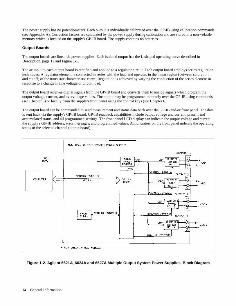
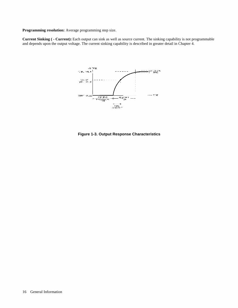
Output response time: Beginning at the time the power supply has finished processing a VSET command (change outputvoltage), the maximum time for the output voltage to settle to within a settling band about the final value from anyspecified operating point. This value must be added to the command processing time to obtain total programming time (seeFigure 1-3). Time constant is the maximum time required for the voltage to reach 63% of its final value.
Temperature coefficient: Maximum change in the regulated output parameter per °C change in ambient temperature aftera 30 minute warmup. Expressed in parts-per-million plus a constant per °C (plus a constant for readback temperaturecoefficient).
Long Term Drift: Maximum change of regulated output voltage or current during an 8-hour period following a 30 minutewarmup, with all influence and control quantities maintained constant. Expressed as a percentage of setting plus a constant.
Short Term Drift: Maximum change of regulated output voltage or current within 30 minutes after a line and/or loadchange. Expressed as a percentage of setting plus a constant.
Output Noise (PARD): PARD replaces the former term ripple and noise. PARD is the periodic and random deviation of dcoutput voltage or current from its average value, over a specified bandwidth and with all influence and control quantitiesmaintained constant.
General Information16
Programming resolution: Average programming step size.
Current Sinking ( - Current): Each output can sink as well as source current. The sinking capability is not programmableand depends upon the output voltage. The current sinking capability is described in greater detail in Chapter 4.
Figure 1-3. Output Response Characteristics

General Information 17
Table 1-2. Specifications PERFORMANCE SPECIFICATIONS (0 to 55°C unless otherwise specified) Outputs: 40 W Low 40 W High 80 W Low 80 W High Voltage Voltage Voltage Voltage DC Output Ranges: All outputs will accept voltage programming commands 1% higher than those listed and current programming commands 3% higher than those listed. Also, the minimum programmable current values are slightly above zero amps for each output. (See Table 5-4). Low Range 0-7 V; 0-5 A 0-20 V; 0-2 A 0-7 V; 0-10 A 0-20 V: 0-4 A High Range
0-20 V; 0-2 A
0-50 V: 0-0.8 A
0-20 V; 0-4 A 0-50 V; 0-2 A
Load Effect (Regulation): When remote sensing, add 1 mV to the value listed for each 200 mV drop in the - V load lead. Voltage 2 mV 2 mV 2 mV 2 mV + Current 1 mA
0.5 mA 2 mA 1 mA
Source Effect:
Voltage 0.01% + 1 mV 0.01% + 1 mV 0.01% + 1 mV 0.01% + 1 mV + Current
0.06% + 1 mA
0.06% + 1 mA
0.06% + 2 mA
0.06% + 2 mA
Programming Accuracy: (At calibration temperature ± 5°C) Voltage 19 mV + 0.06% 50 mV + 0.06% 19 mV + 0.06% 50 mV + 0.06% + Current OVP
50 mA + 0.16% 200 mV + 0.13%
20 mA + 0.16% 475 mV + 0.13%
100 mA + 0.16% 200 mV + 0.13%
40 mA + 0.16% 475 mV + 0.13%
Readback Accuracy: (At calibration temperature ±5°C) Voltage 20 mV + 0.05% 50 mV +0.05% 20 mV + 0.05% 50 mV +0.05% + Current 10 mA +0.1% 4 mA + 0.1% 20 mA +0.1% 8 mA +0.1% - Current 25 mA +0.2% 8 mA +0.2%
50 mA +0.2% 20 mA +0.2%
Load Transient Recovery Time: 75 μS maximum to recover to within 75 mV of nominal value following a load change within the range 300 mA to full load for low voltage units, and 150 mA to full load for high voltage units. Maximum Output Noise (PARD):
CV peak-to-peak (20 Hz--20 MHz)
3 mV 3 mV 3 mV 3 mV
CV rms (20 Hz--10 MHz)
0.5 mV 0.5 mV 0.5 mV 0.5 mV
+ CC rms (20Hz--10 MHz)
1 mA 1 mA 2 mA 2 mA
AC Input Voltage and Frequency: Nominal Line = 100,120, 220, or 240 Vac Amplitude = + 6%, -13% of nominal line voltage Frequency Range = 47-66 Hz Note: At low line, the supply will operate with up to 3/4 Ω line resistance.
General Information18
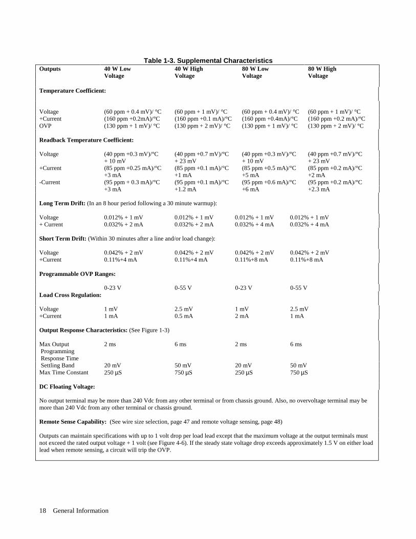
Table 1-3. Supplemental CharacteristicsOutputs 40 W Low 40 W High 80 W Low 80 W High
Voltage Voltage Voltage Voltage
Temperature Coefficient:
Voltage (60 ppm + 0.4 mV)/ °C (60 ppm + 1 mV)/ °C (60 ppm + 0.4 mV)/ °C (60 ppm + 1 mV)/ °C+Current (160 ppm +0.2mA)/°C (160 ppm +0.1 mA)/°C (160 ppm +0.4mA)/°C (160 ppm +0.2 mA)/°COVP (130 ppm + 1 mV)/ °C (130 ppm + 2 mV)/ °C (130 ppm + 1 mV)/ °C (130 ppm + 2 mV)/ °C
Readback Temperature Coefficient:
Voltage (40 ppm +0.3 mV)/°C (40 ppm +0.7 mV)/°C (40 ppm +0.3 mV)/°C (40 ppm +0.7 mV)/°C+ 10 mV + 23 mV + 10 mV + 23 mV
+Current (85 ppm +0.25 mA)/°C (85 ppm +0.1 mA)/°C (85 ppm +0.5 mA)/°C (85 ppm +0.2 mA)/°C+3 mA +1 mA +5 mA +2 mA
-Current (95 ppm + 0.3 mA)/°C (95 ppm +0.1 mA)/°C (95 ppm +0.6 mA)/°C (95 ppm +0.2 mA)/°C+3 mA +1.2 mA +6 mA +2.3 mA
Long Term Drift: (In an 8 hour period following a 30 minute warmup):
Voltage 0.012% + 1 mV 0.012% + 1 mV 0.012% + 1 mV 0.012% + 1 mV+ Current 0.032% + 2 mA 0.032% + 2 mA 0.032% + 4 mA 0.032% + 4 mA
Short Term Drift: (Within 30 minutes after a line and/or load change):
Voltage 0.042% + 2 mV 0.042% + 2 mV 0.042% + 2 mV 0.042% + 2 mV+Current 0.11%+4 mA 0.11%+4 mA 0.11%+8 mA 0.11%+8 mA
Programmable OVP Ranges:
0-23 V 0-55 V 0-23 V 0-55 VLoad Cross Regulation:
Voltage 1 mV 2.5 mV 1 mV 2.5 mV+Current 1 mA 0.5 mA 2 mA 1 mA
Output Response Characteristics: (See Figure 1-3)
Max Output Programming Response Time
2 ms 6 ms 2 ms 6 ms
Settling Band 20 mV 50 mV 20 mV 50 mVMax Time Constant 250 µS 750 µS 250 µS 750 µS
DC Floating Voltage:
No output terminal may be more than 240 Vdc from any other terminal or from chassis ground. Also, no overvoltage terminal may bemore than 240 Vdc from any other terminal or chassis ground.
Remote Sense Capability: (See wire size selection, page 47 and remote voltage sensing, page 48)
Outputs can maintain specifications with up to 1 volt drop per load lead except that the maximum voltage at the output terminals mustnot exceed the rated output voltage + 1 volt (see Figure 4-6). If the steady state voltage drop exceeds approximately 1.5 V on either loadlead when remote sensing, a circuit will trip the OVP.
General Information 19
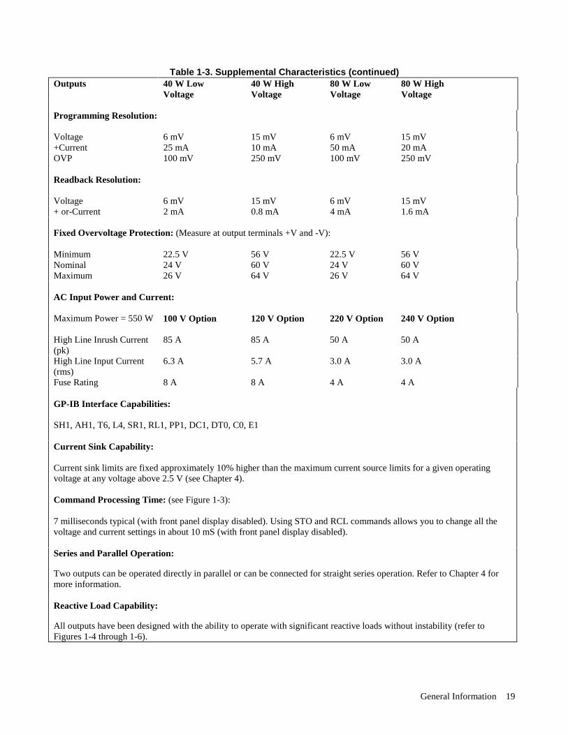
Table 1-3. Supplemental Characteristics (continued)Outputs 40 W Low 40 W High 80 W Low 80 W High
Voltage Voltage Voltage Voltage
Programming Resolution:
Voltage 6 mV 15 mV 6 mV 15 mV+Current 25 mA 10 mA 50 mA 20 mAOVP 100 mV 250 mV 100 mV 250 mV
Readback Resolution:
Voltage 6 mV 15 mV 6 mV 15 mV+ or-Current 2 mA 0.8 mA 4 mA 1.6 mA
Fixed Overvoltage Protection: (Measure at output terminals +V and -V):
Minimum 22.5 V 56 V 22.5 V 56 VNominal 24 V 60 V 24 V 60 VMaximum 26 V 64 V 26 V 64 V
AC Input Power and Current:
Maximum Power = 550 W 100 V Option 120 V Option 220 V Option 240 V Option
High Line Inrush Current(pk)
85 A 85 A 50 A 50 A
High Line Input Current(rms)
6.3 A 5.7 A 3.0 A 3.0 A
Fuse Rating 8 A 8 A 4 A 4 A
GP-IB Interface Capabilities:
SH1, AH1, T6, L4, SR1, RL1, PP1, DC1, DT0, C0, E1
Current Sink Capability:
Current sink limits are fixed approximately 10% higher than the maximum current source limits for a given operatingvoltage at any voltage above 2.5 V (see Chapter 4).
Command Processing Time: (see Figure 1-3):
7 milliseconds typical (with front panel display disabled). Using STO and RCL commands allows you to change all thevoltage and current settings in about 10 mS (with front panel display disabled).
Series and Parallel Operation:
Two outputs can be operated directly in parallel or can be connected for straight series operation. Refer to Chapter 4 formore information.
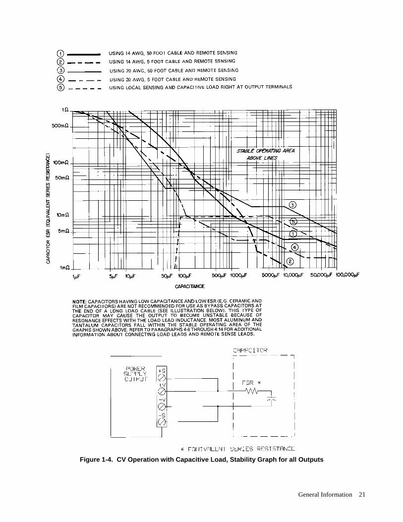
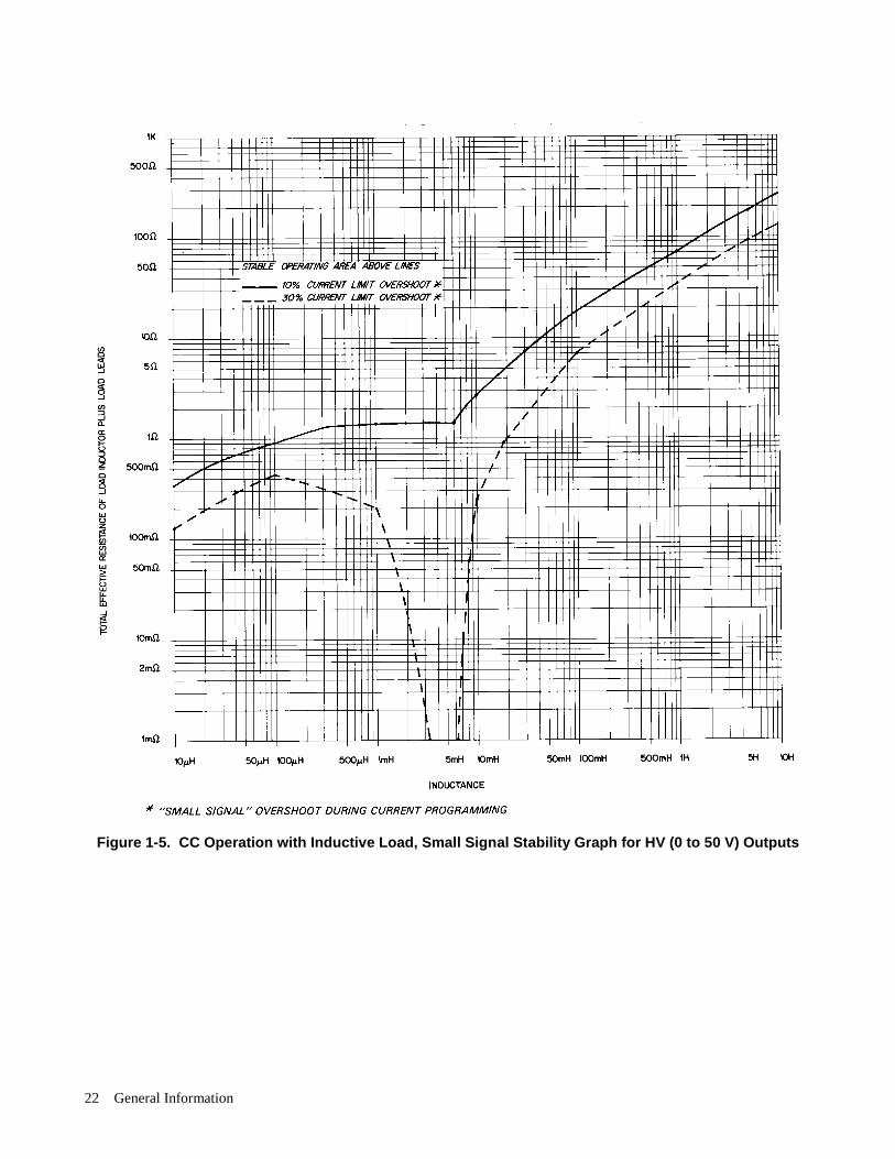
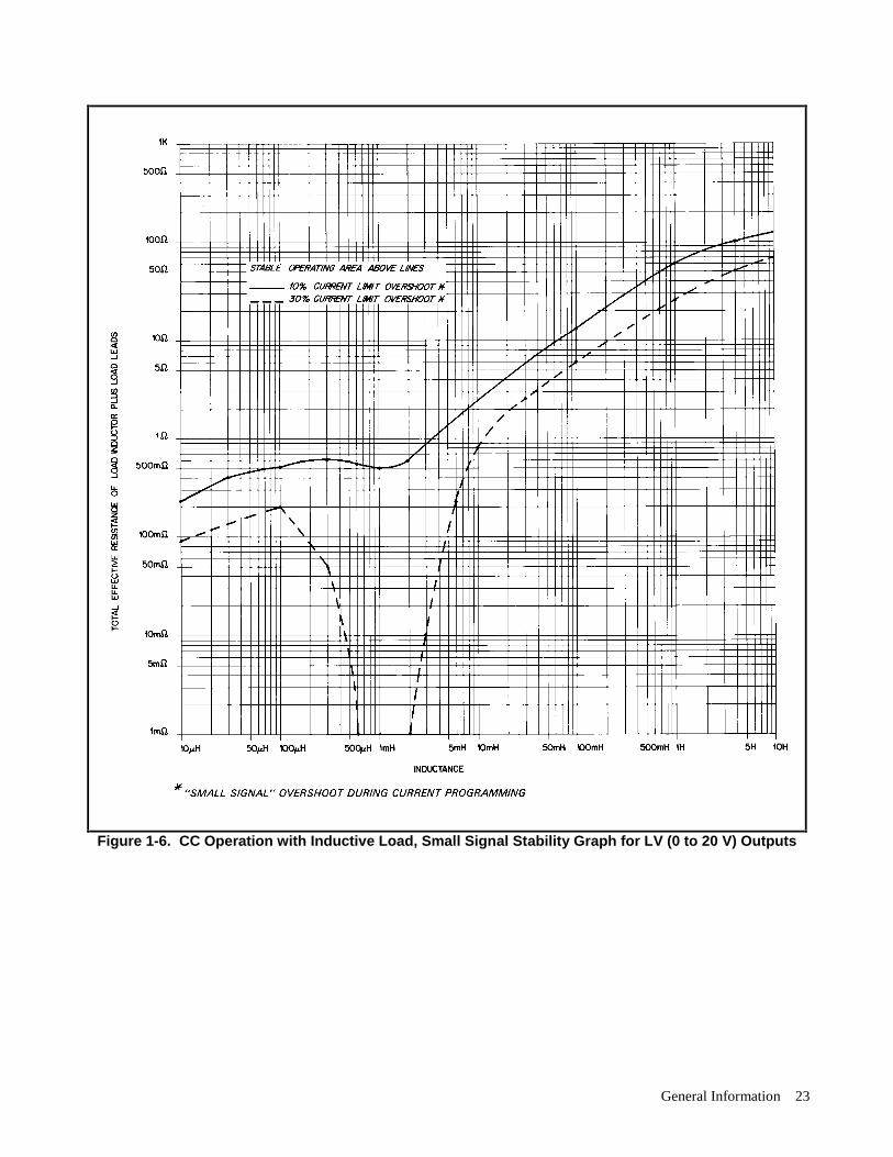
Reactive Load Capability:
All outputs have been designed with the ability to operate with significant reactive loads without instability (refer toFigures 1-4 through 1-6).

General Information20
Table 1-3. Supplemental Characteristics (continued)Output Impedance:
Approximated by a resistance in parallel with an inductance (see graphs in Figure 1-7). The values for each output are:
40 W Low Voltage 40 W High Voltage 80 W Low Voltage 80 W High Voltage
0.15Ω, 2.0µH 0.3 Ω, 5 µH 0.15 Ω, 0.8 µH 0.5 Ω, 3 µH
Safety Agency Compliance:
This series of power supplies is designed to comply with the following standards: IEC 348, UL 1244, andCSA 22.2 No. 231.
Dimensions: (all models)
Height = 132.6 mm (5.22in.)Width = 425.5 mm (16.75in.)Depth = 497.8 mm (19.6in.)
Weight: (all models):Net Weight = 17.4 kg (38 lb.)Shipping Weight = 22.7 kg (50 lb.)
General Information 21
Figure 1-4. CV Operation with Capacitive Load, Stability Graph for all Outputs
General Information22
Figure 1-5. CC Operation with Inductive Load, Small Signal Stability Graph for HV (0 to 50 V) Outputs
General Information 23
Figure 1-6. CC Operation with Inductive Load, Small Signal Stability Graph for LV (0 to 20 V) Outputs

General Information24
Figure 1-7. Output Impedance (Typical) Graphs (See Supplemental Characteristics, Table 1-1)

Installation 25
2Installation
Introduction
This chapter contains instructions for checking and mounting your power supply, connecting your supply to ac power,converting it from one line voltage to another, and connecting the GP-IB cable.
The power supply generates operating magnetic fields which may affect the operation of other instruments. If yourinstrument is susceptible to magnetic fields, do not locate it in the immediate vicinity of the power supply. Typically, atthree inches from the power supply, the electromagnetic field is less than 5 gauss.
NOTE The Agilent 662xA power supplies generate operating magnetic fields which may affect the operation ofother instruments. If your instrument is susceptible to operating magnetic fields, position it more than 3inches from the Agilent 662xA supply.
Initial Inspection
Your instrument was thoroughly inspected and tested before it left the factory. As soon as you receive it, remove the powersupply from its packing case and check to make sure it has not been damaged in shipment. Check that there are no brokenconnectors or keys, and that the cabinet and panel surfaces are free from dents and scratches. Check the rear panel terminalblocks and front panel display for any cracks. If damage is found, you should file a claim with the carrier immediately andnotify the Agilent Technologies Sales and Service office nearest you.
Chapter 3 of this manual includes an electrical turn-on check-out procedure which, when carried out successfully, will giveyou a high level of confidence that the power supply is operating in accordance with its specifications. Detailed electricalchecks complete with verification procedures are included in the Service Manual.
Keep the original packing materials for the carrier’ s inspection if there was damage, or in case any equipment has to bereturned to Agilent Technologies. Warranty information is printed on the inside cover of this manual. Remember to send adetailed description of the failure and symptoms when returning the power supply for service. Your Agilent TechnologiesSales and Service office will furnish the address of the nearest service office to which the instrument can be shipped .
Location and Cooling
Your power supply can operate without loss of performance within the temperature range of 0 to 55 ° C (measured at thefan intake). The fan, located at the rear of the unit, cools the supply by drawing air in through the openings on the rear paneland exhausting it through openings on the sides. Using Agilent Technologies rack mount kits will not impede the flow ofair.
Because the power supply is fan cooled, it must be installed in a location that allows sufficient space at the rear and thesides for adequate circulation of air. Either side may be restricted to have as little as 1 inch (25 mm) space.
Figure 2-1 gives the dimensions of the power supply cabinet. These dimensions apply to all five models. The cabinet hasplastic feet that are shaped to ensure self-alignment when stacked with other Agilent Technologies System II cabinets. Thefeet may be removed for rack mounting.
The power supply can be mounted in a standard 19 inch rack panel or enclosure. Rack mounting accessories for this unitare listed on page 12, under Options of Chapter 1. Complete installation instructions are included with each rack mountingkit. Instrument support rails are required for non-stationary installations. These are normally supplied with the cabinet andare not included with the rack mounting kits.
Installation26
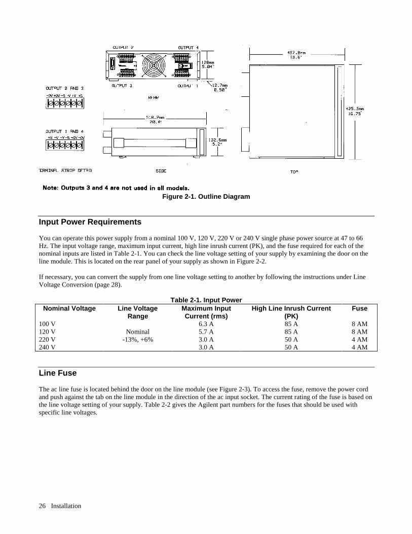
Figure 2-1. Outline Diagram
Input Power Requirements
You can operate this power supply from a nominal 100 V, 120 V, 220 V or 240 V single phase power source at 47 to 66Hz. The input voltage range, maximum input current, high line inrush current (PK), and the fuse required for each of thenominal inputs are listed in Table 2-1. You can check the line voltage setting of your supply by examining the door on theline module. This is located on the rear panel of your supply as shown in Figure 2-2.
If necessary, you can convert the supply from one line voltage setting to another by following the instructions under LineVoltage Conversion (page 28).
Table 2-1. Input PowerNominal Voltage Line Voltage
RangeMaximum InputCurrent (rms)
High Line Inrush Current(PK)
Fuse
100 V 6.3 A 85 A 8 AM120 V Nominal 5.7 A 85 A 8 AM220 V -13%, +6% 3.0 A 50 A 4 AM240 V 3.0 A 50 A 4 AM
Line Fuse
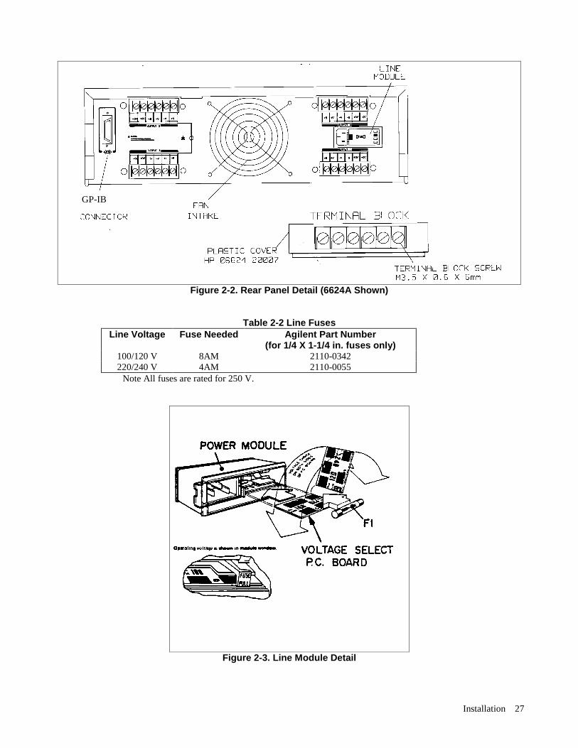
The ac line fuse is located behind the door on the line module (see Figure 2-3). To access the fuse, remove the power cordand push against the tab on the line module in the direction of the ac input socket. The current rating of the fuse is based onthe line voltage setting of your supply. Table 2-2 gives the Agilent part numbers for the fuses that should be used withspecific line voltages.
Installation 27
Figure 2-2. Rear Panel Detail (6624A Shown)
Table 2-2 Line FusesLine Voltage Fuse Needed Agilent Part Number
(for 1/4 X 1-1/4 in. fuses only)100/120 V 8AM 2110-0342220/240 V 4AM 2110-0055
Note All fuses are rated for 250 V.
Figure 2-3. Line Module Detail
GP-IB
Installation28
Power Cord
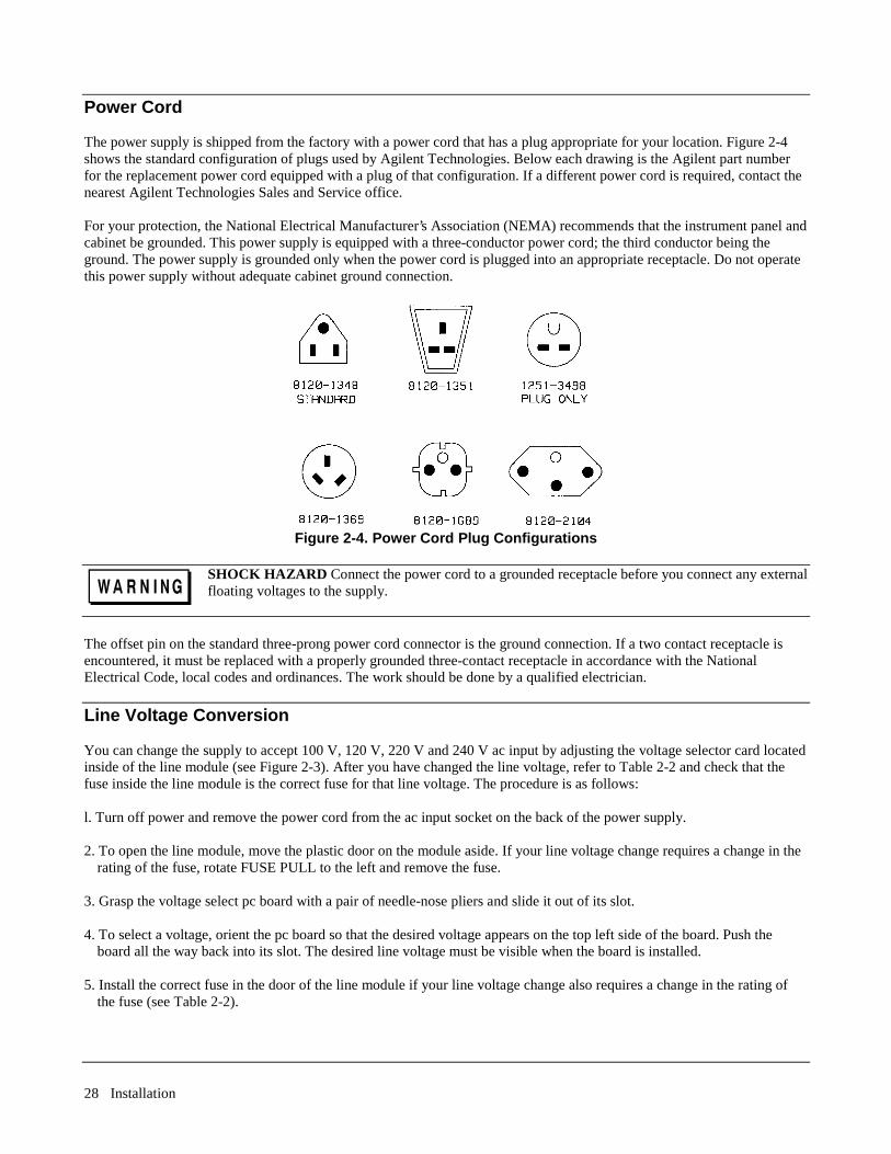
The power supply is shipped from the factory with a power cord that has a plug appropriate for your location. Figure 2-4shows the standard configuration of plugs used by Agilent Technologies. Below each drawing is the Agilent part numberfor the replacement power cord equipped with a plug of that configuration. If a different power cord is required, contact thenearest Agilent Technologies Sales and Service office.
For your protection, the National Electrical Manufacturer’s Association (NEMA) recommends that the instrument panel andcabinet be grounded. This power supply is equipped with a three-conductor power cord; the third conductor being theground. The power supply is grounded only when the power cord is plugged into an appropriate receptacle. Do not operatethis power supply without adequate cabinet ground connection.
Figure 2-4. Power Cord Plug Configurations
SHOCK HAZARD Connect the power cord to a grounded receptacle before you connect any externalfloating voltages to the supply.
The offset pin on the standard three-prong power cord connector is the ground connection. If a two contact receptacle isencountered, it must be replaced with a properly grounded three-contact receptacle in accordance with the NationalElectrical Code, local codes and ordinances. The work should be done by a qualified electrician.
Line Voltage Conversion
You can change the supply to accept 100 V, 120 V, 220 V and 240 V ac input by adjusting the voltage selector card locatedinside of the line module (see Figure 2-3). After you have changed the line voltage, refer to Table 2-2 and check that thefuse inside the line module is the correct fuse for that line voltage. The procedure is as follows:
l. Turn off power and remove the power cord from the ac input socket on the back of the power supply.
2. To open the line module, move the plastic door on the module aside. If your line voltage change requires a change in therating of the fuse, rotate FUSE PULL to the left and remove the fuse.
3. Grasp the voltage select pc board with a pair of needle-nose pliers and slide it out of its slot.
4. To select a voltage, orient the pc board so that the desired voltage appears on the top left side of the board. Push theboard all the way back into its slot. The desired line voltage must be visible when the board is installed.
5. Install the correct fuse in the door of the line module if your line voltage change also requires a change in the rating ofthe fuse (see Table 2-2).
Installation 29
FIRE HAZARD Make sure the replacement fuse is one of the same type (size) and rating (amps) thatis consistent with the voltage level you are operating at. Do not use a substitute fuse; use a fusewith the same Agilent Part number listed in Table 2-2.
6. Close the door of the line module and insert the power cord in the ac input socket. Your power supply is now configuredto operate at the voltage you selected.
GP-IB Interface Connector
The GP-IB connector on the rear panel connects your power supply to your computer and other GP-IB devices (see Figure2-2). Chapter 1, page 12 lists the cables and cable accessories that are available from Agilent Technologies. An GP-IBsystem can be connected together in any configuration (star, linear, or both) as long as the following rules are observed:
1. The total number of devices, including the computer, is no more than 15.
2. The total length of all the cables used is no more than two meters times the number of devices connected together, up to amaximum of 20 meters.
NOTE IEEE Std. 488-1978 states that you should exercise caution if your individual cable lengths exceed 4m.
Do not stack more than three connector blocks together on any GP-IB connector. The resultant leverage can exert excessiveforce on the mounting panels. Make sure that all connectors are fully seated and that the lock screws are firmly fingertightened. Do not use a screwdriver. Use a screwdriver only for the removal of the screws.


Getting Started 31
3Getting Started
Introduction
This chapter is intended for the first time user of the supply. It provides four main discussions:
• Front Panel Controls and Indicators• Turning on Your Supply• Checking Out Your Supply Using Local Control• Introduction to Remote Operation First, the supply’s front panel controls and indicators are briefly described. Some of the controls and indicators will be usedin the Turn On and Checkout procedures that follow. Chapter 6 describes how to use all of the front panel controls. Successful completion of the turn on and checkout procedures ensures with a high level of confidence that your supply isoperating properly. Complete performance testing and troubleshooting procedures are given in the Service Manual (AgilentPart No. 5957-6379). The checkout procedures are performed locally from the front panel. In addition to checking the operation of your supply,these simple step-by-step checkout procedures will help the first time user become familiar with operating the supply fromthe front panel. When you have completed the checkout procedures, you are then introduced to the fundamentals of operating the supplyremotely from a computer. You will learn how to send a command to the supply from the computer and how to get databack to the computer from the power supply. A few of the most often used power supply commands will be described tohelp you get started and become familiar with the basics of programming your supply. After completing this chapter, you can proceed to Chapter 4 to find out how to make load connections to your supply’soutputs and then to Chapter 5 (Remote Control) and/or Chapter 6 (Local Control) to learn all the details about operatingyour supply.
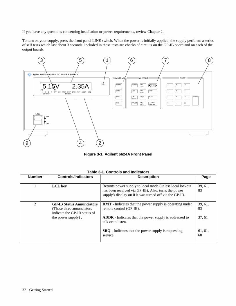
Front Panel Controls and Indicators The power supply’s controls and indicators are shown in Figure 3-1 and are described in Table 3-1. Note that the front panelcontrols are identical for Agilent Models 6621A-6624A, and 6627A, except for the number of OUTPUT annunciators(number 3 in Figure 3-1). The Agilent Model 6624A, shown in Figure 3-1, has four outputs (as does the Agilent 6627A),Agilent Models 6621A and 6622A each have two outputs, and Agilent Model 6623A has three outputs. Table 3-1, in addition to providing a brief description of each control and indicator, lists the paragraphs in which the use ofeach control and indicator is described. Because most of the functions performed by the front panel controls can also beperformed remotely by power supply commands, the corresponding paragraphs in Chapter 5 (Remote Operation) are listedin Table 3-1 where applicable.
Turning On Your Supply The following paragraphs describe the power-on sequence which includes a self test of most of the power supply’s circuits. Before you turn on your supply, make sure that:• The line module on the rear panel is set to match your input line voltage. • The proper fuse is installed and the line cord is plugged in.
Getting Started32
If you have any questions concerning installation or power requirements, review Chapter 2. To turn on your supply, press the front panel LINE switch. When the power is initially applied, the supply performs a seriesof self tests which last about 3 seconds. Included in these tests are checks of circuits on the GP-IB board and on each of theoutput boards.
SYSTEM OUTPUT ENTRY
LINEON
OFF
LCL ADDR
ERR
STO
RCL
METER
DLY
FAULT
UN MASK
OCP
OUTPUTSELECT
VSET
ISET
OUTPUTON/OFF
ENTER
7 8 9
4 5 6
1 2 3
0 .
6624A SYSTEM DC POWER SUPPLY
1 2 3 4 CV CC UNR OCP ERR RMT ADDR SRQ ENBLD-- OUTPUT --
5.15V 2.35A OV SET
OV RST
OC RST
9 4 2
87613 5
Figure 3-1. Agilent 6624A Front Panel
Table 3-1. Controls and Indicators Number
Controls/lndicators
Description
Page
1 LCL key
Returns power supply to local mode (unless local lockouthas been received via GP-IB). Also, turns the powersupply’s display on if it was turned off via the GP-IB.
39, 61,83
2 GP-IB Status Annunciators (These three annunciatorsindicate the GP-IB status ofthe power supply) .
RMT - Indicates that the power supply is operating underremote control (GP-IB). ADDR - Indicates that the power supply is addressed totalk or to listen. SRQ - Indicates that the power supply is requestingservice.
39, 61,83 37, 61 61, 61,68

Getting Started 33
Table 3-1. Controls and Indicators (continued) Number
Controls/lndicators
Description
Page
3 OUTPUT Annunciators
Indicate which output channel has been selected for frontpanel control and/or display. (Only one output annunciatorcan be on at a time.)
36, 37,83, 83
4 Power Supply Status Annunciators (These five annunciatorsindicate the status of thepower supply).
CV - Indicates that the selected output channel is in theconstant voltage mode. CC - Indicates that the selected output channel is in thepositive constant current mode ( + CC) or the negativecurrent limit ( - CC) mode. UNR - Indicates that the selected output channel isunregulated; i.e., it is not regulated by CV or CC controlloops. OCP ENBLD - Indicates that the overcurrent protectionfunction for the selected channel is enabled. ERR - Indicates that a programming or hardware error hasoccurred and that the ERR bit in the serial poll register hasnot been cleared.
37, 43,83 37, 43,83 43 37, 63,83 43, 68,84
5 Alphanumeric LCDDisplay (When power isturned on, all segments willbe displayed forapproximately 2 seconds).
Normally displays the measured output voltage andcurrent for the selected channel. When programmed fromthe front panel, the function being programmed (e.g.VSET), the output channel (e.g. 2), and the present value(e.g. 2.250) will be displayed. Error conditions will bespelled out in alpha characters.
36, 37, 43, 69,83, 83
6 System Control Keys (Thesefour control keys affect theentire power supply and areindependent of the outputselected).
ADDR - Displays the power supply’s GP-IB address. Youcan change the address using the numeric entry keys. Youcannot query or change the address remotely (over the GP-IB). ERR- Displays a programming or hardware error messageand clears the ERR bit in the serial poll register. STO - Used in conjunction with the numeric entry keys tostore the present output voltage and current settings for alloutputs in the specified internal register (1 to 10). Eachregister contains voltage and current settings for all outputchannels. RCL - Used in conjunction with the numeric entry keys torecall the settings from the specified internal register (1 to10). All outputs are set to the recalled values.
37, 61,83 69, 84 63, 84 63, 84
Getting Started34
Table 3-1. Controls and Indicators (continued)
Number
Controls/lndicators
Description
Page
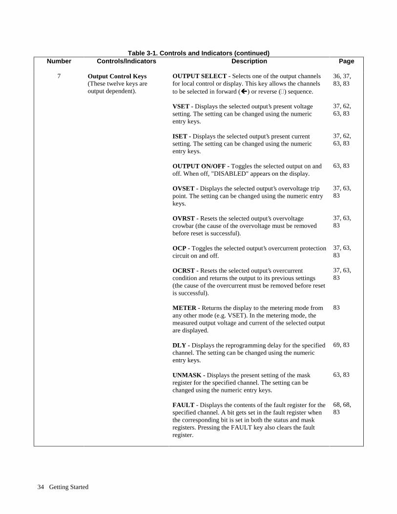
7 Output Control Keys(These twelve keys areoutput dependent).
OUTPUT SELECT - Selects one of the output channelsfor local control or display. This key allows the channelsto be selected in forward (Ï) or reverse (Ð) sequence. VSET - Displays the selected output’s present voltagesetting. The setting can be changed using the numericentry keys. ISET - Displays the selected output’s present currentsetting. The setting can be changed using the numericentry keys. OUTPUT ON/OFF - Toggles the selected output on andoff. When off, "DISABLED" appears on the display. OVSET - Displays the selected output’s overvoltage trippoint. The setting can be changed using the numeric entrykeys. OVRST - Resets the selected output’s overvoltagecrowbar (the cause of the overvoltage must be removedbefore reset is successful). OCP - Toggles the selected output’s overcurrent protectioncircuit on and off. OCRST - Resets the selected output’s overcurrentcondition and returns the output to its previous settings(the cause of the overcurrent must be removed before resetis successful). METER - Returns the display to the metering mode fromany other mode (e.g. VSET). In the metering mode, themeasured output voltage and current of the selected outputare displayed. DLY - Displays the reprogramming delay for the specifiedchannel. The setting can be changed using the numericentry keys. UNMASK - Displays the present setting of the maskregister for the specified channel. The setting can bechanged using the numeric entry keys. FAULT - Displays the contents of the fault register for thespecified channel. A bit gets set in the fault register whenthe corresponding bit is set in both the status and maskregisters. Pressing the FAULT key also clears the faultregister.
36, 37, 83, 83 37, 62,63, 83 37, 62,63, 83 63, 83 37, 63,83 37, 63,83 37, 63,83 37, 63,83 83 69, 83 63, 83 68, 68, 83
Getting Started 35
Table 3-1. Controls and Indicators (continued) Number
Controls/lndicators
Description
Page
8 Numeric Entry Keys (These keys are used inconjunction with many of theSystem Control and OutputControl keys to enter thedesired values into the powersupply.
0 to 9 - Set the value of the specified function and (e.g. VSET 16.550) ←(backspace) - Erases the previous keystroke. Depressingthis key without setting a value places the display in themetering mode. ENTER- Enters the values on the display for the specifiedfunction, initiates the function, and returns the display tothe metering mode. Pressing this key without setting avalue will result in retention of the previous values andreturning the display to the metering mode.
37, 83,84 83 37, 83,84
9 LINE Switch
Turns ac power on and off.
37
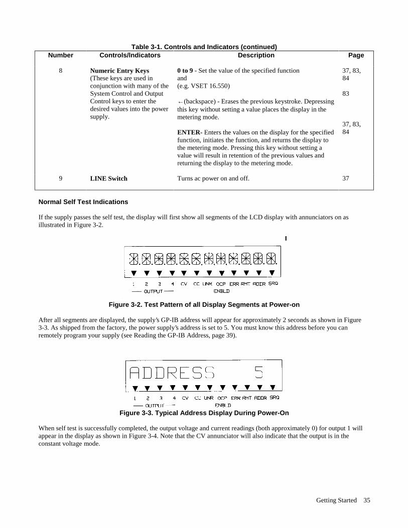
Normal Self Test Indications If the supply passes the self test, the display will first show all segments of the LCD display with annunciators on asillustrated in Figure 3-2.
Figure 3-2. Test Pattern of all Display Segments at Power-on
After all segments are displayed, the supply’s GP-IB address will appear for approximately 2 seconds as shown in Figure 3-3. As shipped from the factory, the power supply’s address is set to 5. You must know this address before you canremotely program your supply (see Reading the GP-IB Address, page 39).
Figure 3-3. Typical Address Display During Power-On
When self test is successfully completed, the output voltage and current readings (both approximately 0) for output 1 willappear in the display as shown in Figure 3-4. Note that the CV annunciator will also indicate that the output is in theconstant voltage mode.

Getting Started36
Figure 3-4. Typical Display at Power-On
Self-Test Errors If the supply fails the power-on self-test, all power supply outputs will remain disabled (off) and the display will indicatethe type of failure and the output channel on which it occurred. Figure 3-5 shows that self-test detected an error in outputchannel 3. Error messages that could appear on the display if self-test fails are listed below. Self-test error messages areexplained in Appendix D and troubleshooting procedures are given in the Service Manual for the Agilent 6621A-6624A,and 6627A Power Supplies. You may also call your Agilent Sales office for help.
Power-On Self Test Error Messages HDW ERR CH "N" 8291 FAILED TIMER FAILED CV DAC CH "N" CC DAC CH "N" OV DAC CH "N" FUSE CH “N”
NOTE "N" specifies the failed output channel number 1,2,3, or 4 as applicable.
Figure 3-5. Sample Self-Test Failure Display
Checking Out Your Supply Using Local Control The following procedures use the display and keys on the front panel to check each of your power supply's outputs. No testequipment, other than a jumper wire (14 AWG), is required to perform these tests. The tests must be repeated for eachoutput of your particular supply. The checkout consists of voltage, overvoltage, and current tests. It is assumed that powerhas already been turned on, the supply has passed the power-on self-test, loads are not connected to any of the supply'soutputs, and sense clips are connected between the sense terminals and the output terminals.
NOTE The following procedures are identical for all models and for all outputs. Use the OUTPUT SELECT keyto select an output to be tested. If an output fails any of the tests, refer to the troubleshooting section inthe Service Manual.
Getting Started 37
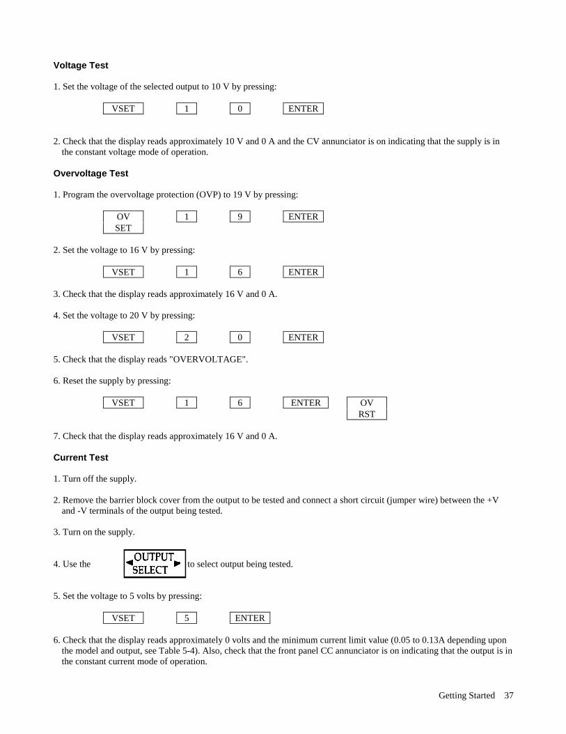
Voltage Test 1. Set the voltage of the selected output to 10 V by pressing:
VSET 1 0 ENTER 2. Check that the display reads approximately 10 V and 0 A and the CV annunciator is on indicating that the supply is in
the constant voltage mode of operation. Overvoltage Test 1. Program the overvoltage protection (OVP) to 19 V by pressing:
OV 1 9 ENTER SET
2. Set the voltage to 16 V by pressing:
VSET 1 6 ENTER 3. Check that the display reads approximately 16 V and 0 A. 4. Set the voltage to 20 V by pressing:
VSET 2 0 ENTER 5. Check that the display reads "OVERVOLTAGE". 6. Reset the supply by pressing:
VSET 1 6 ENTER OV RST
7. Check that the display reads approximately 16 V and 0 A. Current Test 1. Turn off the supply. 2. Remove the barrier block cover from the output to be tested and connect a short circuit (jumper wire) between the +V
and -V terminals of the output being tested. 3. Turn on the supply. 4. Use the to select output being tested. 5. Set the voltage to 5 volts by pressing:
VSET 5 ENTER 6. Check that the display reads approximately 0 volts and the minimum current limit value (0.05 to 0.13A depending upon
the model and output, see Table 5-4). Also, check that the front panel CC annunciator is on indicating that the output is inthe constant current mode of operation.

Getting Started38
7. Set the current to 0.5 A by pressing:
ISET . 5 ENTER 8. Check that the display reads approximately 0 V and 0.5 A. 9. Enable the overcurrent protection circuit by pressing:
OCP 10. Check that the OCP ENBLD annunciator is on indicating that overcurrent protection is enabled and the display reads
"OVERCURRENT". When in overcurrent, the output is disabled. 11. Disable the overcurrent protection circuit by pressing:
OCP 12. Reset the output by pressing:
OC RST
13. Check that the display reads approximately 0 V and 0.5 A. 14. Turn off the supply and remove the jumper from the output terminals. Repeat the tests given on pages 37 & 38 for the other output channel (s) using the key.
Introduction To Remote Operation The following paragraphs explain the fundamentals of operating the supply remotely from a computer. Only a fewcommonly used programming commands will be discussed. Refer to Chapter 5 for a detailed description of all thecommands. The intent of this discussion is to help first time users to quickly become familiar with operating their supplyfrom a computer. The programming examples that follow assume that a computer is connected to the GP-IB connector on the rear of yoursupply (see Chapter 2), power is applied, and loads are not connected to any of the supply’s outputs. The examples used areprimarily for Agilent Series 200 computers using Agilent BASIC language. Read the manuals for your particular computerto find out which statements you must use. Enter/Output Statements The programming statements you use to operate your supply from remote depend on your computer and its language. Inparticular, you need to know the statements your computer uses to output and enter information. For example, the AgilentBASIC language statement that addresses the power supply to listen and sends the command to the power supply is:
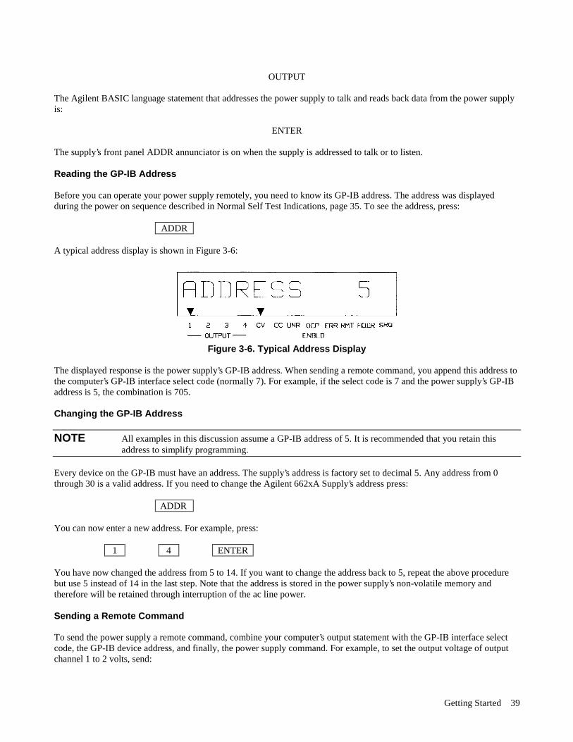
Getting Started 39
OUTPUT
The Agilent BASIC language statement that addresses the power supply to talk and reads back data from the power supplyis:
ENTER The supply’s front panel ADDR annunciator is on when the supply is addressed to talk or to listen. Reading the GP-IB Address Before you can operate your power supply remotely, you need to know its GP-IB address. The address was displayedduring the power on sequence described in Normal Self Test Indications, page 35. To see the address, press:
ADDR A typical address display is shown in Figure 3-6:
Figure 3-6. Typical Address Display
The displayed response is the power supply’s GP-IB address. When sending a remote command, you append this address tothe computer’s GP-IB interface select code (normally 7). For example, if the select code is 7 and the power supply’s GP-IBaddress is 5, the combination is 705. Changing the GP-IB Address
NOTE All examples in this discussion assume a GP-IB address of 5. It is recommended that you retain thisaddress to simplify programming.
Every device on the GP-IB must have an address. The supply’s address is factory set to decimal 5. Any address from 0through 30 is a valid address. If you need to change the Agilent 662xA Supply’s address press:
ADDR You can now enter a new address. For example, press:
1 4 ENTER You have now changed the address from 5 to 14. If you want to change the address back to 5, repeat the above procedurebut use 5 instead of 14 in the last step. Note that the address is stored in the power supply’s non-volatile memory andtherefore will be retained through interruption of the ac line power. Sending a Remote Command To send the power supply a remote command, combine your computer’s output statement with the GP-IB interface selectcode, the GP-IB device address, and finally, the power supply command. For example, to set the output voltage of outputchannel 1 to 2 volts, send:
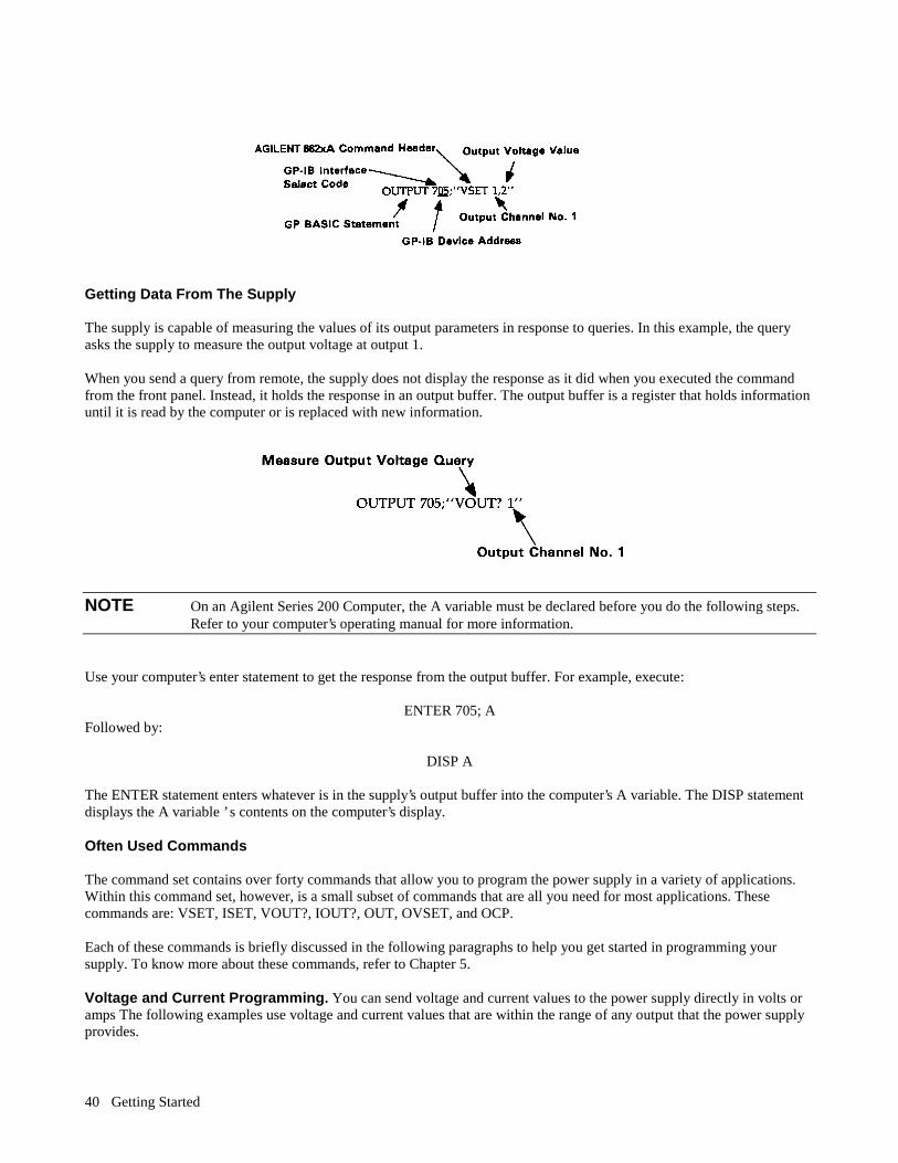
Getting Started40
Getting Data From The Supply The supply is capable of measuring the values of its output parameters in response to queries. In this example, the queryasks the supply to measure the output voltage at output 1. When you send a query from remote, the supply does not display the response as it did when you executed the commandfrom the front panel. Instead, it holds the response in an output buffer. The output buffer is a register that holds informationuntil it is read by the computer or is replaced with new information.
NOTE On an Agilent Series 200 Computer, the A variable must be declared before you do the following steps.Refer to your computer’s operating manual for more information.
Use your computer’s enter statement to get the response from the output buffer. For example, execute:
ENTER 705; A Followed by:
DISP A The ENTER statement enters whatever is in the supply’s output buffer into the computer’s A variable. The DISP statementdisplays the A variable ’ s contents on the computer’s display. Often Used Commands The command set contains over forty commands that allow you to program the power supply in a variety of applications.Within this command set, however, is a small subset of commands that are all you need for most applications. Thesecommands are: VSET, ISET, VOUT?, IOUT?, OUT, OVSET, and OCP. Each of these commands is briefly discussed in the following paragraphs to help you get started in programming yoursupply. To know more about these commands, refer to Chapter 5. Voltage and Current Programming. You can send voltage and current values to the power supply directly in volts oramps The following examples use voltage and current values that are within the range of any output that the power supplyprovides.
Getting Started 41
To set the voltage of output 1 to 5 volts, send:
OUTPUT 705; "VSET 1,5" To set the current of output 2 to 450 milliamps, send:
OUTPUT 705; "ISET 2,.450" Output Voltage and Current Measurement. You can instruct the supply to measure the actual output voltage andcurrent at a specified output using the VOUT? and IOUT? queries, respectively. To measure the output voltage at output 1, send:
OUTPUT 705; "VOUT? 1’’ To get the measurement from the output buffer, send:
ENTER 705; A
DISP A The computer should display a reading of approximately 5 volts. To measure the output current at output 2 send:
OUTPUT 705, "IOUT? 2" To get the measurement from the output buffer, send:
ENTER 705; A
DISP A
Output On/Off. You can turn a specified output on or off. Individual outputs can be controlled as shown below. To turn off output 1, send:
OUTPUT 705; OUT 1,0
When an output is turned off, it is set to 0 volts and to the minimum current limit value. To turn on output 1, send:
OUTPUT 705; "OUT 1,1"
When an output is turned on, it will return to the voltage and current settings determined by the present VSET and ISETvalues. Overvoltage Setting. You can send an overvoltage setting value to the power supply directly in volts. If the outputvoltage exceeds this setting, the output crowbar is fired, and the output voltage is quickly downprogrammed and disabled(0. volts output). To set the overvoltage value of output 2 to 3.5 volts, send:
OUTPUT 705; "OVSET 2,3.5"

Getting Started42
Overcurrent Protection. The output will go to the off state (0 volts and min. current) when the overcurrent protection(OCP) feature is enabled and the output is in the + CC mode. To enable the overcurrent protection mode for output 2, send:
OUTPUT 705; "OCP 2,1" To disable the overcurrent protection mode for output 2, send:
OUTPUT 705; "OCP 2,0" When overcurrent protection is disabled and the output is in + CC mode, the output current will be limited to and will stayat the ISET value. Returning the Supply to Local Mode In the remote mode (RMT annunciator on), the front panel keys have no effect on any of the supply’s outputs and only thecomputer can control the supply. However, you can still use the front panel display to monitor the output voltage andcurrent or check any of the present settings (VSET, ISET, OVSET, etc.) of the selected output channel. If you want to use the front panel keys to change the output settings, you must return the supply to the local mode. You canreturn the supply to the local mode (provided that the local lockout command has not been received from the computer) bypressing the LCL key. A change between the local and remote modes (or vice versa) will not result in a change in the powersupply outputs. Refer to Chapter 6 for additional details on using the LCL key and operating the supply in the local mode.
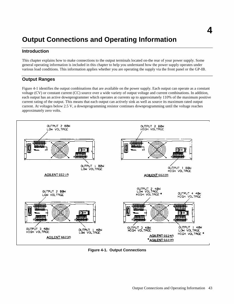
Output Connections and Operating Information 43
4 Output Connections and Operating Information
Introduction This chapter explains how to make connections to the output terminals located on-the rear of your power supply. Somegeneral operating information is included in this chapter to help you understand how the power supply operates undervarious load conditions. This information applies whether you are operating the supply via the front panel or the GP-IB.
Output Ranges Figure 4-1 identifies the output combinations that are available on the power supply. Each output can operate as a constantvoltage (CV) or constant current (CC) source over a wide variety of output voltage and current combinations. In addition,each output has an active downprogrammer which operates at currents up to approximately 110% of the maximum positivecurrent rating of the output. This means that each output can actively sink as well as source its maximum rated outputcurrent. At voltages below 2.5 V, a downprogramming resistor continues downprogramming until the voltage reachesapproximately zero volts.
Figure 4-1. Output Connections
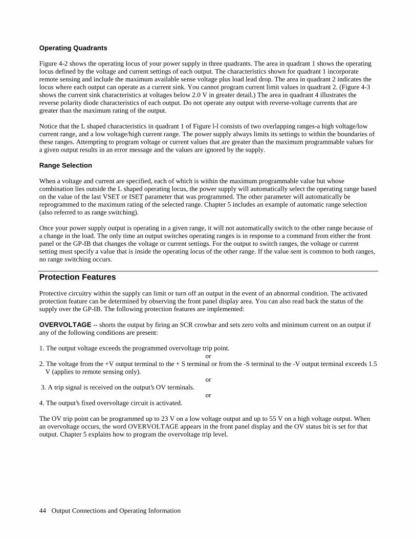
Output Connections and Operating Information 44
Operating Quadrants Figure 4-2 shows the operating locus of your power supply in three quadrants. The area in quadrant 1 shows the operatinglocus defined by the voltage and current settings of each output. The characteristics shown for quadrant 1 incorporateremote sensing and include the maximum available sense voltage plus load lead drop. The area in quadrant 2 indicates thelocus where each output can operate as a current sink. You cannot program current limit values in quadrant 2. (Figure 4-3shows the current sink characteristics at voltages below 2.0 V in greater detail.) The area in quadrant 4 illustrates thereverse polarity diode characteristics of each output. Do not operate any output with reverse-voltage currents that aregreater than the maximum rating of the output. Notice that the L shaped characteristics in quadrant 1 of Figure l-l consists of two overlapping ranges-a high voltage/lowcurrent range, and a low voltage/high current range. The power supply always limits its settings to within the boundaries ofthese ranges. Attempting to program voltage or current values that are greater than the maximum programmable values fora given output results in an error message and the values are ignored by the supply. Range Selection When a voltage and current are specified, each of which is within the maximum programmable value but whosecombination lies outside the L shaped operating locus, the power supply will automatically select the operating range basedon the value of the last VSET or ISET parameter that was programmed. The other parameter will automatically bereprogrammed to the maximum rating of the selected range. Chapter 5 includes an example of automatic range selection(also referred to as range switching). Once your power supply output is operating in a given range, it will not automatically switch to the other range because ofa change in the load. The only time an output switches operating ranges is in response to a command from either the frontpanel or the GP-IB that changes the voltage or current settings. For the output to switch ranges, the voltage or currentsetting must specify a value that is inside the operating locus of the other range. If the value sent is common to both ranges,no range switching occurs.
Protection Features Protective circuitry within the supply can limit or turn off an output in the event of an abnormal condition. The activatedprotection feature can be determined by observing the front panel display area. You can also read back the status of thesupply over the GP-IB. The following protection features are implemented: OVERVOLTAGE -- shorts the output by firing an SCR crowbar and sets zero volts and minimum current on an output ifany of the following conditions are present: 1. The output voltage exceeds the programmed overvoltage trip point.
or 2. The voltage from the +V output terminal to the + S terminal or from the -S terminal to the -V output terminal exceeds 1.5
V (applies to remote sensing only). or
3. A trip signal is received on the output’s OV terminals. or
4. The output’s fixed overvoltage circuit is activated. The OV trip point can be programmed up to 23 V on a low voltage output and up to 55 V on a high voltage output. Whenan overvoltage occurs, the word OVERVOLTAGE appears in the front panel display and the OV status bit is set for thatoutput. Chapter 5 explains how to program the overvoltage trip level.
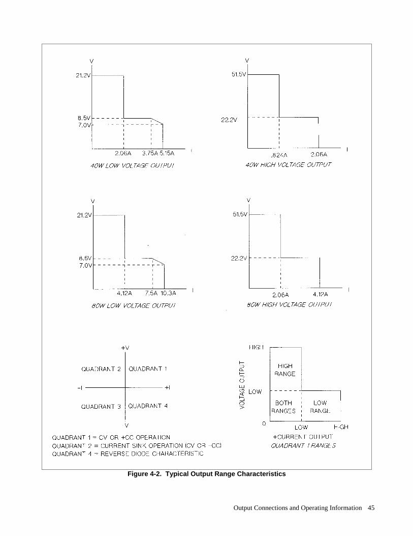
Output Connections and Operating Information 45
Figure 4-2. Typical Output Range Characteristics
Output Connections and Operating Information 46
A fixed overvoltage threshold of approximately 120% of the maximum rated output voltage is built into each output.Because the fixed overvoltage circuit is biased from the output terminals, it can be activated and provide protection evenwhen the supply is not connected to the ac power line. The OVRST command restores the programmed voltage and current values and clears the OV once the cause of theovervoltage has been eliminated. OVERCURRENT--when the overcurrent protection feature is enabled, and the output is sourcing current and enters the +CC operating mode, the output will be disabled (set to zero volts and minimum current) and the word OVERCURRENTwill appear on the front panel display. In addition the OC status bit is set for that output. The OCRST command restores theprogrammed voltage and current values and clears the OC once the cause of the overcurrent condition has been eliminated.Refer to Chapter V for programming details. UNREGULATED OUTPUT--the supply informs the user when output regulation is not guaranteed. This can occur whenattempting to sink excessive currents below 2.5 volts or when operating outputs in parallel. The UNR annunciator on thefront panel and the UNR bit in the status register indicate that the specified output is unregulated. Line voltage dropout oran incorrectly set ac power module can also cause the output to become unregulated. If line voltage dropout continues, thesupply shuts down and will return to the power-up condition when normal line voltage is restored. OVERTEMPERATURE--shuts down the linear pass and downprogrammer of the output that has reached an unsafeoperating temperature. Operation of the other outputs is unaffected. An overtemperature can occur because of excessivelyhigh ambient temperature, a blocked fan, or insufficient space at the sides for adequate air circulation. When anovertemperature condition occurs, the word OVERTEMP appears in the front panel display and the OT status bit is set.This circuit resets automatically and restores the output approximately 30 seconds after the temperature drops sufficientlyfor safe operation. ERROR--if the power supply receives an invalid command either through the front panel or the GP-IB, the ERRannunciator on the front panel comes on and the ERR bit in the serial poll register is set. The power supply does not executethe command and remains at previously set values. Pushing the ERR button in local mode displays the error message andclears the error. The error indicator may also indicate that an instrument failure has occurred. Refer to Appendix D forfurther details.
CONNECTING THE LOAD Each terminal block cover on the rear panel is secured by a locking tab which snaps into a slot at the left of the terminalblock. To remove, insert a screwdriver into this rectangular slot and move the locking tab to the left. When the locking tabreleases, gently pull the terminal block cover away from the terminal block. To reinstall the cover, align it over the terminalblock and gently press it into position until the locking tab engages.
SHOCK HAZARD Turn off ac power before making rear panel connections. All wires and strapsmust be properly connected with terminal block screws securely tightened. Replace terminal blockcovers before reapplying power.
Each rear terminal block has six M3.5 x 0.6 x 6 mm screws for attaching wires (see Figure 2-2). Load connections to thesupply are made at the + V and -V terminals on each terminal block Do. not connect unterminated wires to the loadterminals. Wires used for load connections must be properly terminated with termination connectors securely attached.Remember to replace the impact resistant plastic covers (Agilent P/N 06624-20007) over the terminal blocks after makingconnections.
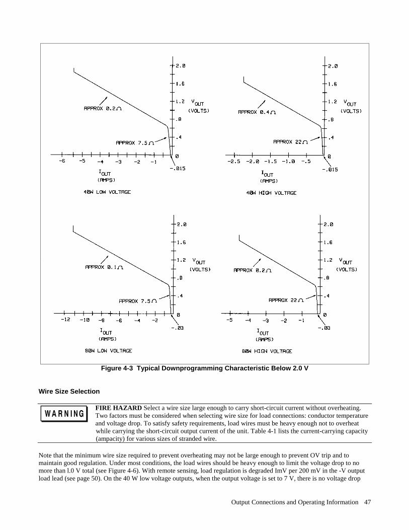
Output Connections and Operating Information 47
Figure 4-3 Typical Downprogramming Characteristic Below 2.0 V
Wire Size Selection
FIRE HAZARD Select a wire size large enough to carry short-circuit current without overheating.Two factors must be considered when selecting wire size for load connections: conductor temperatureand voltage drop. To satisfy safety requirements, load wires must be heavy enough not to overheat while carrying the short-circuit output current of the unit. Table 4-1 lists the current-carrying capacity(ampacity) for various sizes of stranded wire.
Note that the minimum wire size required to prevent overheating may not be large enough to prevent OV trip and tomaintain good regulation. Under most conditions, the load wires should be heavy enough to limit the voltage drop to nomore than l.0 V total (see Figure 4-6). With remote sensing, load regulation is degraded ImV per 200 mV in the -V outputload lead (see page 50). On the 40 W low voltage outputs, when the output voltage is set to 7 V, there is no voltage drop
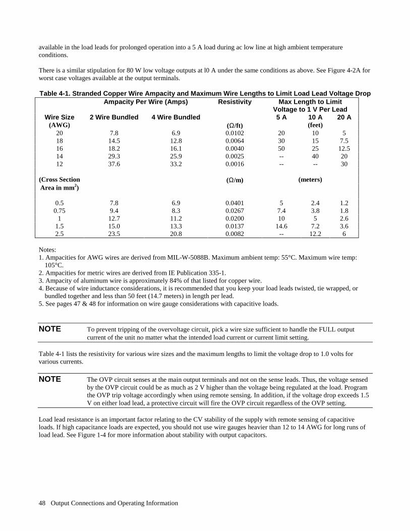
Output Connections and Operating Information 48
available in the load leads for prolonged operation into a 5 A load during ac low line at high ambient temperatureconditions. There is a similar stipulation for 80 W low voltage outputs at l0 A under the same conditions as above. See Figure 4-2A forworst case voltages available at the output terminals. Table 4-1. Stranded Copper Wire Ampacity and Maximum Wire Lengths to Limit Load Lead Voltage Drop
Ampacity Per Wire (Amps) Resistivity Max Length to LimitVoltage to 1 V Per Lead
Wire Size 2 Wire Bundled 4 Wire Bundled 5 A 10 A 20 A (AWG) (Ω/ft) (feet)
20 7.8 6.9 0.0102 20 10 5 18 14.5 12.8 0.0064 30 15 7.5 16 18.2 16.1 0.0040 50 25 12.5 14 29.3 25.9 0.0025 -- 40 20 12 37.6 33.2 0.0016 -- -- 30
(Cross Section (Ω/m) (meters) Area in mm2)
0.5 7.8 6.9 0.0401 5 2.4 1.2 0.75 9.4 8.3 0.0267 7.4 3.8 1.8
1 12.7 11.2 0.0200 10 5 2.6 1.5 15.0 13.3 0.0137 14.6 7.2 3.6 2.5 23.5 20.8 0.0082 -- 12.2 6
Notes: 1. Ampacities for AWG wires are derived from MIL-W-5088B. Maximum ambient temp: 55°C. Maximum wire temp:
105°C. 2. Ampacities for metric wires are derived from IE Publication 335-1. 3. Ampacity of aluminum wire is approximately 84% of that listed for copper wire. 4. Because of wire inductance considerations, it is recommended that you keep your load leads twisted, tie wrapped, or
bundled together and less than 50 feet (14.7 meters) in length per lead. 5. See pages 47 & 48 for information on wire gauge considerations with capacitive loads.
NOTE To prevent tripping of the overvoltage circuit, pick a wire size sufficient to handle the FULL outputcurrent of the unit no matter what the intended load current or current limit setting.
Table 4-1 lists the resistivity for various wire sizes and the maximum lengths to limit the voltage drop to 1.0 volts forvarious currents.
NOTE The OVP circuit senses at the main output terminals and not on the sense leads. Thus, the voltage sensedby the OVP circuit could be as much as 2 V higher than the voltage being regulated at the load. Programthe OVP trip voltage accordingly when using remote sensing. In addition, if the voltage drop exceeds 1.5V on either load lead, a protective circuit will fire the OVP circuit regardless of the OVP setting.
Load lead resistance is an important factor relating to the CV stability of the supply with remote sensing of capacitiveloads. If high capacitance loads are expected, you should not use wire gauges heavier than 12 to 14 AWG for long runs ofload lead. See Figure 1-4 for more information about stability with output capacitors.
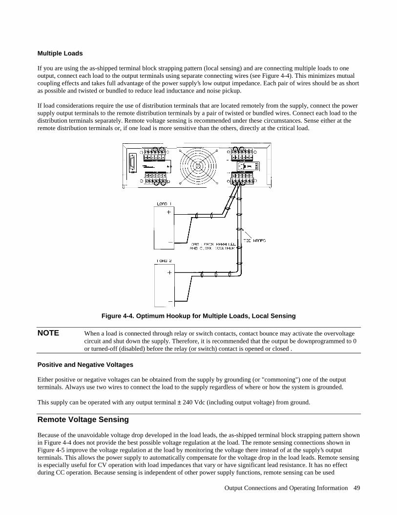
Output Connections and Operating Information 49
Multiple Loads If you are using the as-shipped terminal block strapping pattern (local sensing) and are connecting multiple loads to oneoutput, connect each load to the output terminals using separate connecting wires (see Figure 4-4). This minimizes mutualcoupling effects and takes full advantage of the power supply’s low output impedance. Each pair of wires should be as shortas possible and twisted or bundled to reduce lead inductance and noise pickup. If load considerations require the use of distribution terminals that are located remotely from the supply, connect the powersupply output terminals to the remote distribution terminals by a pair of twisted or bundled wires. Connect each load to thedistribution terminals separately. Remote voltage sensing is recommended under these circumstances. Sense either at theremote distribution terminals or, if one load is more sensitive than the others, directly at the critical load.
Figure 4-4. Optimum Hookup for Multiple Loads, Local Sensing
NOTE When a load is connected through relay or switch contacts, contact bounce may activate the overvoltagecircuit and shut down the supply. Therefore, it is recommended that the output be downprogrammed to 0or turned-off (disabled) before the relay (or switch) contact is opened or closed .
Positive and Negative Voltages Either positive or negative voltages can be obtained from the supply by grounding (or "commoning") one of the outputterminals. Always use two wires to connect the load to the supply regardless of where or how the system is grounded. This supply can be operated with any output terminal ± 240 Vdc (including output voltage) from ground.
Remote Voltage Sensing Because of the unavoidable voltage drop developed in the load leads, the as-shipped terminal block strapping pattern shownin Figure 4-4 does not provide the best possible voltage regulation at the load. The remote sensing connections shown inFigure 4-5 improve the voltage regulation at the load by monitoring the voltage there instead of at the supply’s outputterminals. This allows the power supply to automatically compensate for the voltage drop in the load leads. Remote sensingis especially useful for CV operation with load impedances that vary or have significant lead resistance. It has no effectduring CC operation. Because sensing is independent of other power supply functions, remote sensing can be used
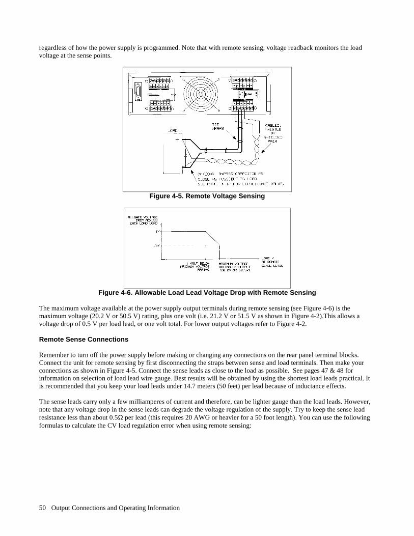
Output Connections and Operating Information 50
regardless of how the power supply is programmed. Note that with remote sensing, voltage readback monitors the loadvoltage at the sense points.
Figure 4-5. Remote Voltage Sensing
Figure 4-6. Allowable Load Lead Voltage Drop with Remote Sensing
The maximum voltage available at the power supply output terminals during remote sensing (see Figure 4-6) is themaximum voltage (20.2 V or 50.5 V) rating, plus one volt (i.e. 21.2 V or 51.5 V as shown in Figure 4-2).This allows avoltage drop of 0.5 V per load lead, or one volt total. For lower output voltages refer to Figure 4-2. Remote Sense Connections Remember to turn off the power supply before making or changing any connections on the rear panel terminal blocks.Connect the unit for remote sensing by first disconnecting the straps between sense and load terminals. Then make yourconnections as shown in Figure 4-5. Connect the sense leads as close to the load as possible. See pages 47 & 48 forinformation on selection of load lead wire gauge. Best results will be obtained by using the shortest load leads practical. Itis recommended that you keep your load leads under 14.7 meters (50 feet) per lead because of inductance effects. The sense leads carry only a few milliamperes of current and therefore, can be lighter gauge than the load leads. However,note that any voltage drop in the sense leads can degrade the voltage regulation of the supply. Try to keep the sense leadresistance less than about 0.5Ω per lead (this requires 20 AWG or heavier for a 50 foot length). You can use the followingformulas to calculate the CV load regulation error when using remote sensing:

Output Connections and Operating Information 51
OUTPUT TYPE FORMULA (40 W & 80 W)
LV Output CV Reg Error(mV) = Rs (Vset
45
Vdrop
1.1- )
HV Output CV Reg Error(mV) = Rs (Vset
105
Vdrop
3.3- )
CV Regulation Error = Remotely sensed voltage will change by this number of millivolts. Rs = Resistance of each sense lead in Ω. Vset = Programmed voltage value in volts. Vdrop = Total drop in the load leads in volts.
In addition, include ±1 mV error per 200 mV drop in the -V load lead independent of Rs value.
Output Noise Considerations Any noise picked up on the sense leads will appear at the supply’s output and may adversely affect CV load regulation.Twist the sense leads or use a ribbon cable to minimize the pickup of external noise. In extremely noisy environments itmay be necessary to shield the sense leads. Ground the shield at the power supply end only; do not use the shield as one ofthe sensing conductors. The noise specifications in Table 1-1 apply at the power supply output terminals when using local sensing. However,voltage transients may be produced at the load by noise induced in the leads or by load current transients acting on theinductance and resistance of the load lead. If it is desirable to keep voltage transient levels to a minimum, place analuminum or a tantalum capacitor, with an approximate value of 10 µF per foot (30.5cm) of load lead, right across the load(see Figure 4-5). Refer to Figure 1-4 for capacitive load stability considerations. Programming Response Time with an Output Capacitor Because voltage programming into an external output capacitor may cause the supply to briefly enter CC operating mode,voltage programming response time may be longer than that specified in Table 1-1. Use the following formula to estimatethe additional response time: Additional = (Added Output Capacitor)(Change in Vout) Response Current Limit Setting Time Open Sense Leads The sense leads are part of the supply’s feedback path. Connect them in such a way so that they do not inadvertentlybecome open circuited. The power supply includes protection resistors that reduce the effect of open sense leads duringremote-sensing operation. If the sense leads open during operation, the supply returns to the local sensing mode, with thevoltage at the output terminals approximately 2.5% higher (low voltage outputs) or approximately 3% higher (high voltageoutputs) than the programmed value.
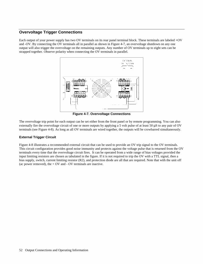
Output Connections and Operating Information 52
Overvoltage Trigger Connections Each output of your power supply has two OV terminals on its rear panel terminal block. These terminals are labeled +OVand -OV. By connecting the OV terminals all in parallel as shown in Figure 4-7, an overvoltage shutdown on any oneoutput will also trigger the overvoltage on the remaining outputs. Any number of OV terminals up to eight sets can bestrapped together. Observe polarity when connecting the OV terminals in parallel.
Figure 4-7. Overvoltage Connections
The overvoltage trip point for each output can be set either from the front panel or by remote programming. You can alsoexternally fire the overvoltage circuit of one or more outputs by applying a 5 volt pulse of at least 50 µS to any pair of OVterminals (see Figure 4-8). As long as all OV terminals are wired together, the outputs will be crowbarred simultaneously. External Trigger Circuit Figure 4-8 illustrates a recommended external circuit that can be used to provide an OV trip signal to the OV terminals.This circuit configuration provides good noise immunity and protects against the voltage pulse that is returned from the OVterminals every time that the overvoltage circuit fires. It can be operated from a wide range of bias voltages provided theinput limiting resistors are chosen as tabulated in the figure. If it is not required to trip the OV with a TTL signal, then abias supply, switch, current limiting resistor (R2), and protection diode are all that are required. Note that with the unit off(ac power removed), the + OV and - OV terminals are inactive.

Output Connections and Operating Information 53
Figure 4-8. External Trigger Circuit
The internal equivalent OV circuit is shown in Figure 4-9. Note the internal DC blocking capacitor, bleed resistor and noisebypass capacitors.
Do not exceed 50 volts maximum between the + OV and the - OV terminals. The OV terminals arerated at ±240 Vdc (including external OV voltage) from chassis ground or any other output terminals.
Figure 4-9. Equivalent Internal OV Trigger Circuit
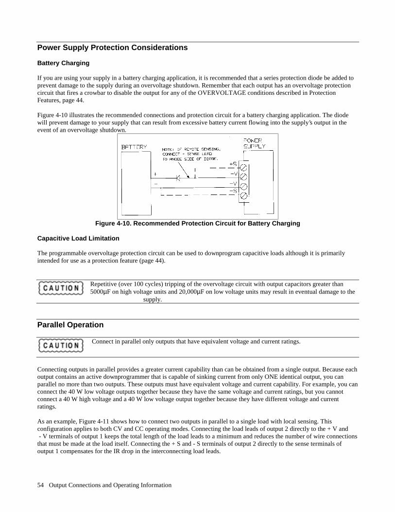
Output Connections and Operating Information 54
Power Supply Protection Considerations Battery Charging If you are using your supply in a battery charging application, it is recommended that a series protection diode be added toprevent damage to the supply during an overvoltage shutdown. Remember that each output has an overvoltage protectioncircuit that fires a crowbar to disable the output for any of the OVERVOLTAGE conditions described in ProtectionFeatures, page 44. Figure 4-10 illustrates the recommended connections and protection circuit for a battery charging application. The diodewill prevent damage to your supply that can result from excessive battery current flowing into the supply’s output in theevent of an overvoltage shutdown.
Figure 4-10. Recommended Protection Circuit for Battery Charging
Capacitive Load Limitation The programmable overvoltage protection circuit can be used to downprogram capacitive loads although it is primarilyintended for use as a protection feature (page 44).
Repetitive (over 100 cycles) tripping of the overvoltage circuit with output capacitors greater than5000µF on high voltage units and 20,000µF on low voltage units may result in eventual damage to the supply.
Parallel Operation
Connect in parallel only outputs that have equivalent voltage and current ratings.
Connecting outputs in parallel provides a greater current capability than can be obtained from a single output. Because eachoutput contains an active downprogrammer that is capable of sinking current from only ONE identical output, you canparallel no more than two outputs. These outputs must have equivalent voltage and current capability. For example, you canconnect the 40 W low voltage outputs together because they have the same voltage and current ratings, but you cannotconnect a 40 W high voltage and a 40 W low voltage output together because they have different voltage and currentratings. As an example, Figure 4-11 shows how to connect two outputs in parallel to a single load with local sensing. Thisconfiguration applies to both CV and CC operating modes. Connecting the load leads of output 2 directly to the + V and - V terminals of output 1 keeps the total length of the load leads to a minimum and reduces the number of wire connectionsthat must be made at the load itself. Connecting the + S and - S terminals of output 2 directly to the sense terminals ofoutput 1 compensates for the IR drop in the interconnecting load leads.

Output Connections and Operating Information 55
CV Operation For CV operation, one output must operate in CC mode and the other output must operate in CV mode. Although eachoutput operates independently of the other, the output that is operating in CV mode will be ’’controlling" the voltageregulation of both outputs. Setting the output voltages as outlined in the following paragraph and configuring the outputs asshown in Figure 4-11 will allow output 1 to operate in CV mode and output 2 to operate in CC mode.
Figure 4-11. Parallel Connections with Local Sensing
To assure that output 2 will be operating in CC mode, you must program output 2’s voltage to a higher value than thevoltage of output 1. One way to accomplish this is to first program output 2 to the maximum allowable voltage setting forthe desired operating range (see Table 4-2 or Figure 4-2). These values are 1% higher than the rated voltage for theoperating range. Then, program output 1’s voltage to the desired operating voltage. The lower voltage setting of output 1will determine the voltage that appears across the load. The current limit point of the paralleled outputs is the sum of bothindividual current limit points. The output current of the parallel combination is the algebraic sum of the individual currentreadbacks. The + OV and - OV terminals of output 1 should be wired to the + OV and - OV terminals of output 2. When programmingthe overvoltage setpoint, set both outputs to the same overvoltage value. When resetting the overvoltage, first disable bothoutputs by using the OUTPUT ON/OFF key or OUT command. Next, reset both overvoltages. Finally, re-enable theoutputs with the OUTPUT ON/OFF key or OUT command.
Table 4-2. Maximum Allowable Voltage Setting Output Type(40 W & 80 W) Maximum Low Range Voltage Maximum High Range Voltage Low Voltage Output 7.07 V 20.2 V High Voltage Output 20.2 V 50.5 V
NOTE Below 2.5 V the downprogrammer cannot sink the maximum rated current. (See Figures 4-2 and 4-3). Tooperate parallel outputs at voltages under 2.5 V, program both outputs to the same voltage setting.Depending on the load, one output may operate in the unregulated mode.

Output Connections and Operating Information 56
CC Operation For CC operation, set the output voltages as outlined in CV operation (page 55), or alternatively, program the voltagesettings of both outputs to the same voltage limit point. Then program the current of each output so that the sum of bothcurrents equals the total desired operating current. The simplest way to accomplish this is to program each output to onehalf of the total desired operating current. Both outputs will operate in the CC mode. Remote Sensing If it is necessary to remote voltage sense at the load, parallel the sense leads of output 1 with the sense leads of output 2 andconnect to the load as shown in Figure 4-12. The outputs can be programmed as previously described. Additionalinformation on programming outputs connected in parallel is given in Appendix B.
Figure 4-12. Parallel Connections with Remote Sensing
Specifications for Parallel Operation Specifications for outputs operating in parallel can be obtained from the specifications for single outputs. Mostspecifications are expressed as a constant or as a percentage (or ppm) plus a constant. For parallel operation, the percentageportion remains unchanged while constant portions or any constants are changed as indicated below. For current readbackaccuracy and temperature coefficient of current readback, use the minus current specifications: Current All parallel specifications referring to current are twice the single output specification except for
programming resolution which is the same for both single output and parallel output operation. Voltage All parallel specifications referring to voltage are the same as for a single output except for CV load
effect, CV load cross regulation, CV source effect, and CV short term drift. Below 2.5 V, these areall twice the voltage programming accuracy (including the percentage portion). CV load effect above2.5 V could be twice the load effect specification for a single output. CV output noise for outputvoltages less than 2.5 V may be slightly higher than the output noise for a single output.
Load TransientRecovery Time
350µs maximum to recover within 100 mV of nominal value following a load change within therange of 0 to full load.
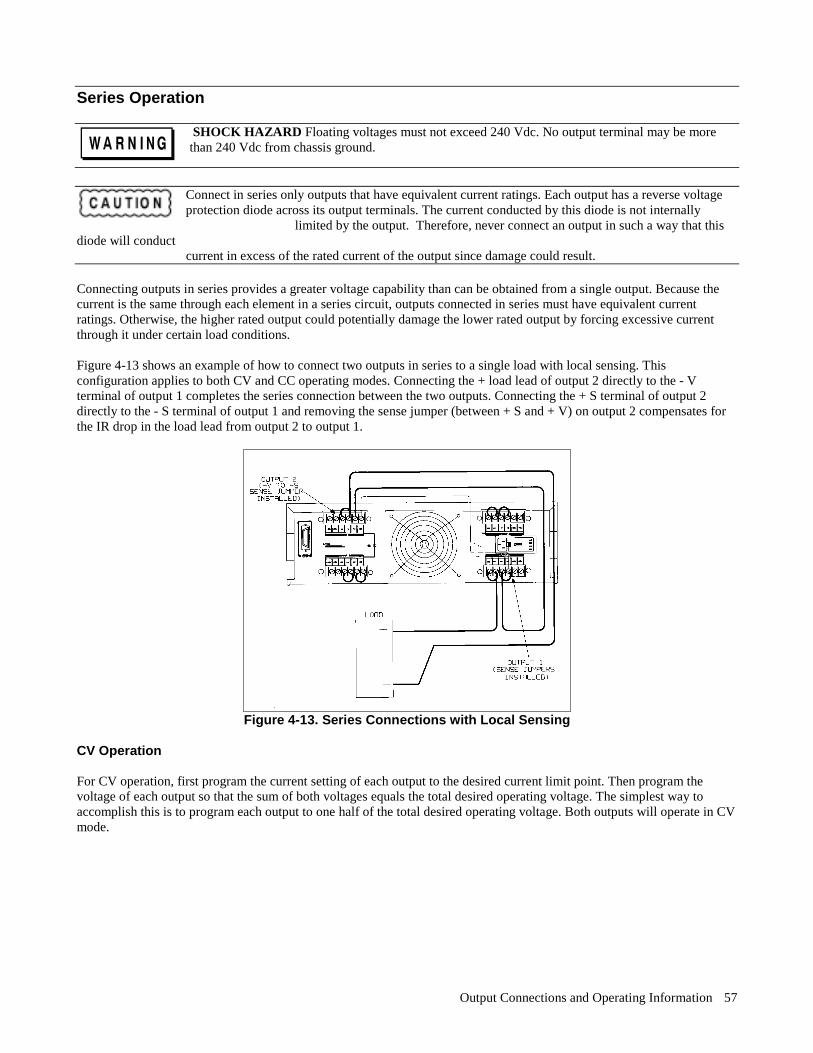
Output Connections and Operating Information 57
Series Operation
SHOCK HAZARD Floating voltages must not exceed 240 Vdc. No output terminal may be morethan 240 Vdc from chassis ground.
Connect in series only outputs that have equivalent current ratings. Each output has a reverse voltageprotection diode across its output terminals. The current conducted by this diode is not internally
limited by the output. Therefore, never connect an output in such a way that thisdiode will conduct current in excess of the rated current of the output since damage could result. Connecting outputs in series provides a greater voltage capability than can be obtained from a single output. Because thecurrent is the same through each element in a series circuit, outputs connected in series must have equivalent currentratings. Otherwise, the higher rated output could potentially damage the lower rated output by forcing excessive currentthrough it under certain load conditions. Figure 4-13 shows an example of how to connect two outputs in series to a single load with local sensing. Thisconfiguration applies to both CV and CC operating modes. Connecting the + load lead of output 2 directly to the - Vterminal of output 1 completes the series connection between the two outputs. Connecting the + S terminal of output 2directly to the - S terminal of output 1 and removing the sense jumper (between + S and + V) on output 2 compensates forthe IR drop in the load lead from output 2 to output 1.
Figure 4-13. Series Connections with Local Sensing
CV Operation For CV operation, first program the current setting of each output to the desired current limit point. Then program thevoltage of each output so that the sum of both voltages equals the total desired operating voltage. The simplest way toaccomplish this is to program each output to one half of the total desired operating voltage. Both outputs will operate in CVmode.
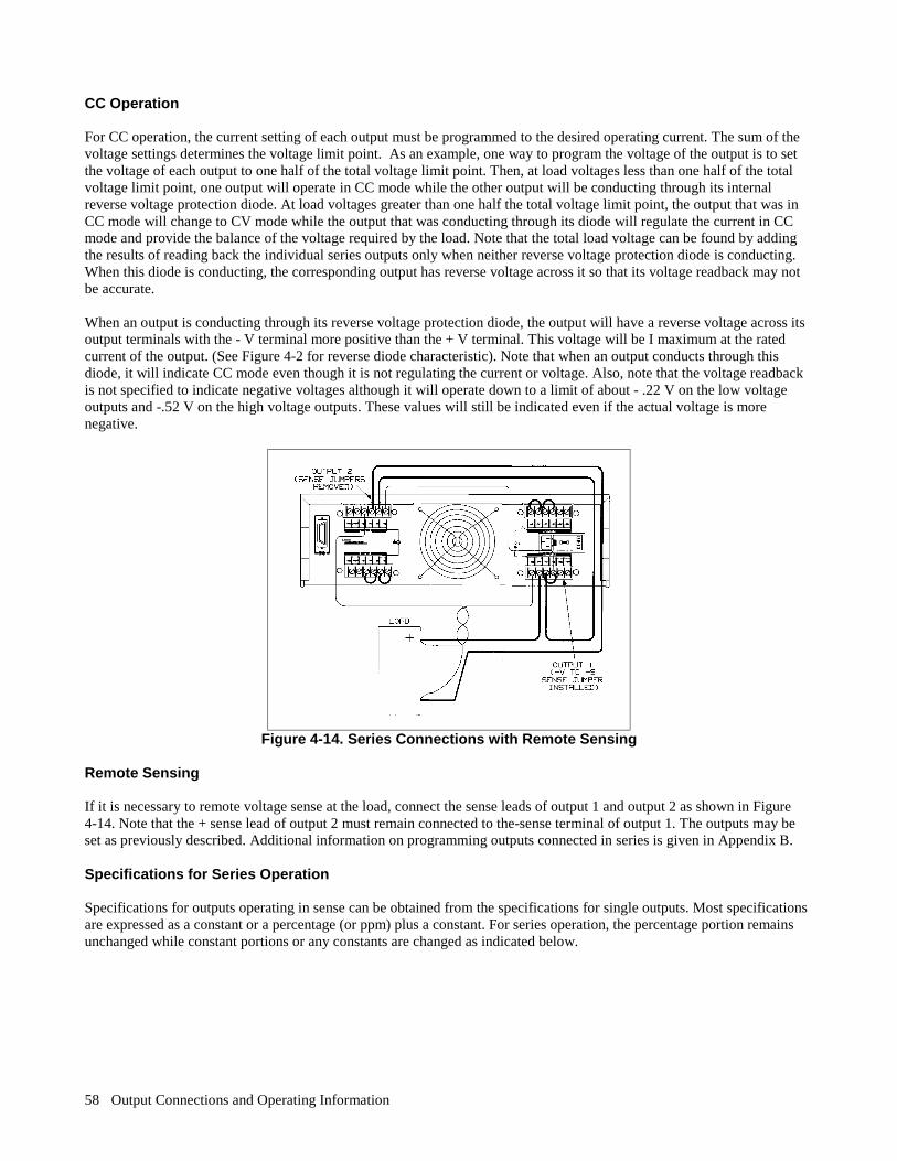
Output Connections and Operating Information 58
CC Operation For CC operation, the current setting of each output must be programmed to the desired operating current. The sum of thevoltage settings determines the voltage limit point. As an example, one way to program the voltage of the output is to setthe voltage of each output to one half of the total voltage limit point. Then, at load voltages less than one half of the totalvoltage limit point, one output will operate in CC mode while the other output will be conducting through its internalreverse voltage protection diode. At load voltages greater than one half the total voltage limit point, the output that was inCC mode will change to CV mode while the output that was conducting through its diode will regulate the current in CCmode and provide the balance of the voltage required by the load. Note that the total load voltage can be found by addingthe results of reading back the individual series outputs only when neither reverse voltage protection diode is conducting.When this diode is conducting, the corresponding output has reverse voltage across it so that its voltage readback may notbe accurate. When an output is conducting through its reverse voltage protection diode, the output will have a reverse voltage across itsoutput terminals with the - V terminal more positive than the + V terminal. This voltage will be I maximum at the ratedcurrent of the output. (See Figure 4-2 for reverse diode characteristic). Note that when an output conducts through thisdiode, it will indicate CC mode even though it is not regulating the current or voltage. Also, note that the voltage readbackis not specified to indicate negative voltages although it will operate down to a limit of about - .22 V on the low voltageoutputs and -.52 V on the high voltage outputs. These values will still be indicated even if the actual voltage is morenegative.
Figure 4-14. Series Connections with Remote Sensing
Remote Sensing If it is necessary to remote voltage sense at the load, connect the sense leads of output 1 and output 2 as shown in Figure 4-14. Note that the + sense lead of output 2 must remain connected to the-sense terminal of output 1. The outputs may beset as previously described. Additional information on programming outputs connected in series is given in Appendix B. Specifications for Series Operation Specifications for outputs operating in sense can be obtained from the specifications for single outputs. Most specificationsare expressed as a constant or a percentage (or ppm) plus a constant. For series operation, the percentage portion remainsunchanged while constant portions or any constants are changed as indicated below.
Output Connections and Operating Information 59
Voltage All series specifications referring to voltage are twice the single output specification except for
programming resolution which is the same as for a single output. Current All series specifications referring to current are the same as for a single output except for CC load
effect, CC load cross regulation, CC source effect, and CC short term drift which are twice the currentprogramming accuracy (including the percentage portion).
Load TransientRecovery Time
Load transient recovery time is the same to within approximately twice the voltage setting band sincethe output impedances of the series combination add together.

Remote Operation 61
5
Remote Operation
Introduction Chapter 3 introduced you to the basics of remote operation and provided a few simple examples using a Series 200computer as the GP-IB controller. This chapter contains all the information required to control your power supply remotelyand discusses in greater detail how each of the commands can be implemented. The material covered is intended for anycontroller capable of using the GP-IB interface functions mentioned in Interface Function, on this page. Four major sub-sections are discussed. These are: 1. GP-IB Operation 2. Programming Syntax 3. Initial Conditions 4. Power Supply Commands The GP-IB section briefly describes the GP-IB interface functions to get you acquainted with remote programming usingthe GP-IB. Under Programming Syntax, the syntax of all commands, the numeric data formats and the programmableranges for all models are given. Initial Conditions highlights the initial values of all the parameters at power-on. PowerSupply Commands will describe all the commands which can be used to program the supply’s functions including statusreporting, error handling, protection features, and voltage and current programming. The power supply commands aresummarized in Appendix C. The examples are written in a generic form to make adaptation to your controller easy. You should be familiar with the useof your controller and its instruction set and how the power supply commands can be incorporated in your controllercommands. If you are not familiar with the operation of the power supply, you are advised to read through Chapters 2through 4 first.
GP-IB Operation Interface Function Remote control is implemented by the GP-IB. It enables instructions to be sent from an external computer equipped with aGP-IB interface. The power supply implements the following IEEE-488 Interface Functions: SH1- Source Handshake SR1 - Service Request AH1 - Acceptor Handshake RL1 - Remote/Local T6 - Talker PP1 - Parallel Poll L4- Listener DC1 - Device Clear The source handshake, acceptor handshake, talker and listener functions are implemented by the interface circuits of thepower supply and the controller. The ADDR annunciator indicates when the power supply is addressed to listen or talk.(The talker function includes the Serial Poll, see page 62). Service Request. This is a message which can be initiated by the power supply to request service from the controller.When the supply is requesting service, it asserts the service request (SRQ) line on the GP-IB to interrupt the controllerproviding the controller is configured to service interrupts. A service request can be generated whenever there is a fault onone of the outputs (up to 4 outputs), a programming error has occurred, or at power on providing certain commands aresent. Service request commands are discussed in detail on page 76.
Remote Operation 62
The SRQ annunciator on the front panel display is turned on when the power supply is requesting service from thecomputer and remains on until the controller conducts a serial poll. A serial poll removes the service request and turns offthe SRQ annunciator regardless of whether the condition that caused the service request continues to exist. The servicerequest is also removed when you send the "CLR" command (see page 73). Remote/Local. The power supply can receive programming information either from the GP-IB (remote) or from the frontpanel (local). When the power supply is in remote, the state of the supply cannot be changed by using the front panel keys,although the LCL key will remain enabled. Remote operation takes precedence over local operation, hence if the supply isaccepting commands remotely and you attempt to change it to local operation, the supply will not allow any local settingsand will remain in remote. You can prevent the front panel from sending programming information by sending the locallockout command. This command is sent only from the GP-IB. If you change from local to remote or vice-versa, there willbe no change in the programmed settings. Parallel Poll. Parallel Poll allows the controller to receive at the same time one bit of data from each of up to eightinstruments connected to the bus. Agilent power supplies designate bit #6, the RQS bit of the serial poll register for thisoperation. By checking the status of this bit, the computer can quickly determine which instruments on the bus requestedservice. Once an instrument is identified, the computer can perform a serial poll to find out the exact cause of the request.Parallel Poll does not reset this service request bit (RQS) in the power supply.
NOTE IEEE-488 does not define what data an instrument should put on a bus in response to parallel poll. Manyinstruments such as Agilent Technologies power supplies indicate the state of their RQS bit, but theoperator should not assume that all instruments on the bus respond to parallel poll with their RQS bit.
Unless remotely configured, the power supply will respond with a 1 on one of the GP-IB data lines if it is requestingservice and its address is between 0 and 7. Addresses 0 through 7 define which data line (1 through 8) the supply willrespond on. If the address is set to 8 or greater, the supply will not respond unless remotely configured. The power supply may be remotely configured to respond with a 0 or 1, on any of the data lines, to indicate that it isrequesting service. This is done in accordance with IEEE-488 1978. Serial Poll. In a serial poll, the controller polls each instrument on the bus one at time. The power supply responds byplacing the contents of the eight-bit serial poll register on the GP-IB data lines. Page 75 discusses the Serial Poll Registerand defines the function of each of the bits. After the serial poll, the service request is cleared and the SRQ annunciator atthe front panel is reset (off). However, the condition that generated the service request may still be present. See page 76. Device Clear. The Device Clear command is typically used in systems to send all devices in the system to a known statewith a single command. It may be implemented as an addressed or an unaddressed command. The power supply CLRcommand performs the same function as Device Clear (see page 73). GP-IB Address Selection You can find out the present address or change the address of the supply by using the front panel ADDR key as describedin Chapter 3. Any address 0 through 30 is a valid address. If you program an address outside this range you will get anumber range error.
NOTE Care should be taken to not select the controller address.

Remote Operation 63
Power-On Service Request (PON) The power supply can request service from the controller when the power is turned on. This request can be enabled ordisabled by sending a PON command (see page 77). When the request is enabled, the supply can generate an SRQ atpower-on or when there is a momentary loss in power. You can execute a serial poll to clear the service request. Table 5-7details the conditions under which a PON command will generate an SRQ.
NOTE The power supply has a non-volatile memory in which it stores certain system variables. Some of thesevariables are the calibration constants, the present supply address, and the present setting of the PONcommand.
Programming Syntax The following paragraphs describe the syntax of the device command that is used to program your power supply. As shownin Figure 5-1, the device command is a specific part of the program statement that your computer will accept. The first partof the statement is computer as well as programming language specific. Figure 5-1 shows the structure of a typicalprogramming statement for an Agilent Series 200 computer. If you are using a different computer or programminglanguage, refer to your computer programming manual to determine the correct syntax for this portion of the programstatement. This section of the manual is only concerned with the device command portion (the part inside the quotes forSeries 200 computers with BASIC) of the program statement.
Figure 5-1. Typical Program Statement for Series 200 Computers
Figure 5-2 shows the possible syntax forms for the device commands that are used to program the power supply. Syntaxforms for the calibration commands that are discussed in Appendix A are also included. The oblong shape at the left of thesyntax forms contains the command header which must be entered as shown in Tables 5-1 and 5-2. Commands are acceptedin either uppercase or lowercase letters (ASCII characters). Circles contain characters that must be entered exactly asshown. Characters such as a space <SP> or a comma are used to separate elements in the command string. Characters suchas a line feed < LF > or a semicolon are used to terminate the command string. Rectangles contain parameters that followthe command header lines and arrows indicate the correct paths through the syntax diagrams. Numeric Data The power supply will accept numeric data in implicit point, explicit point, or scientific notation. A general syntax diagramfor numeric data is included in Figure 5-2. Implicit point notation means that numbers do not contain a decimal point;integers for example. Numbers written in explicit notation contain a decimal point, such as 12.35. In scientific notation, theletter E stands for "10 raised to". For example, 1.2E3 is read as 1.2 times 10 raised to the 3rd power, which equals 1,200.Plus and minus signs are considered numeric characters and are optional. If you program a number with an accuracy that isgreater than the resolution of the supply, the number will automatically be rounded to the nearest multiple of the powersupply’s resolution. Table 5-1 gives the ranges for numeric data that is sent to the supply. The power supply will also return numeric data (ASCII characters) to your computer. The format of the numbers returneddepends upon the type of data requested. Table 5-2 gives the format for data returned to the computer in response to any ofthe queries that are listed.
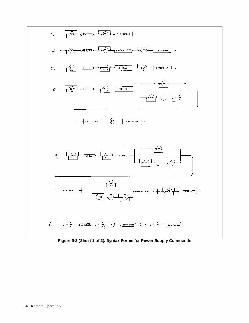
Remote Operation 64
Figure 5-2 (Sheet 1 of 2). Syntax Forms for Power Supply Commands
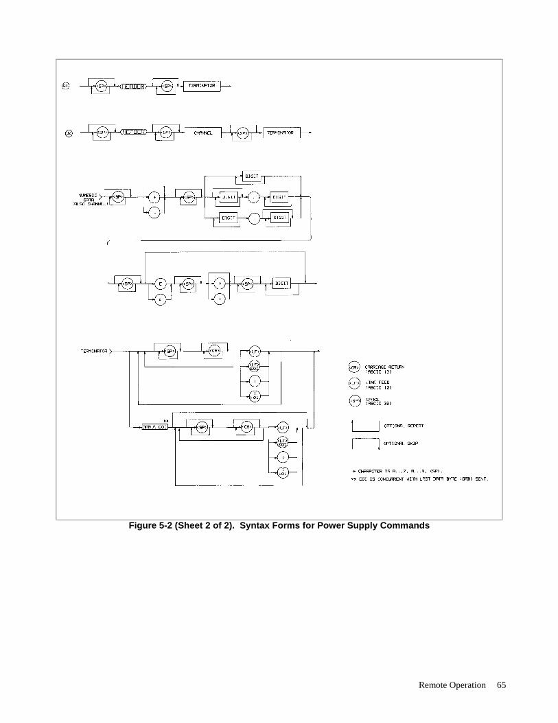
Remote Operation 65
Figure 5-2 (Sheet 2 of 2). Syntax Forms for Power Supply Commands
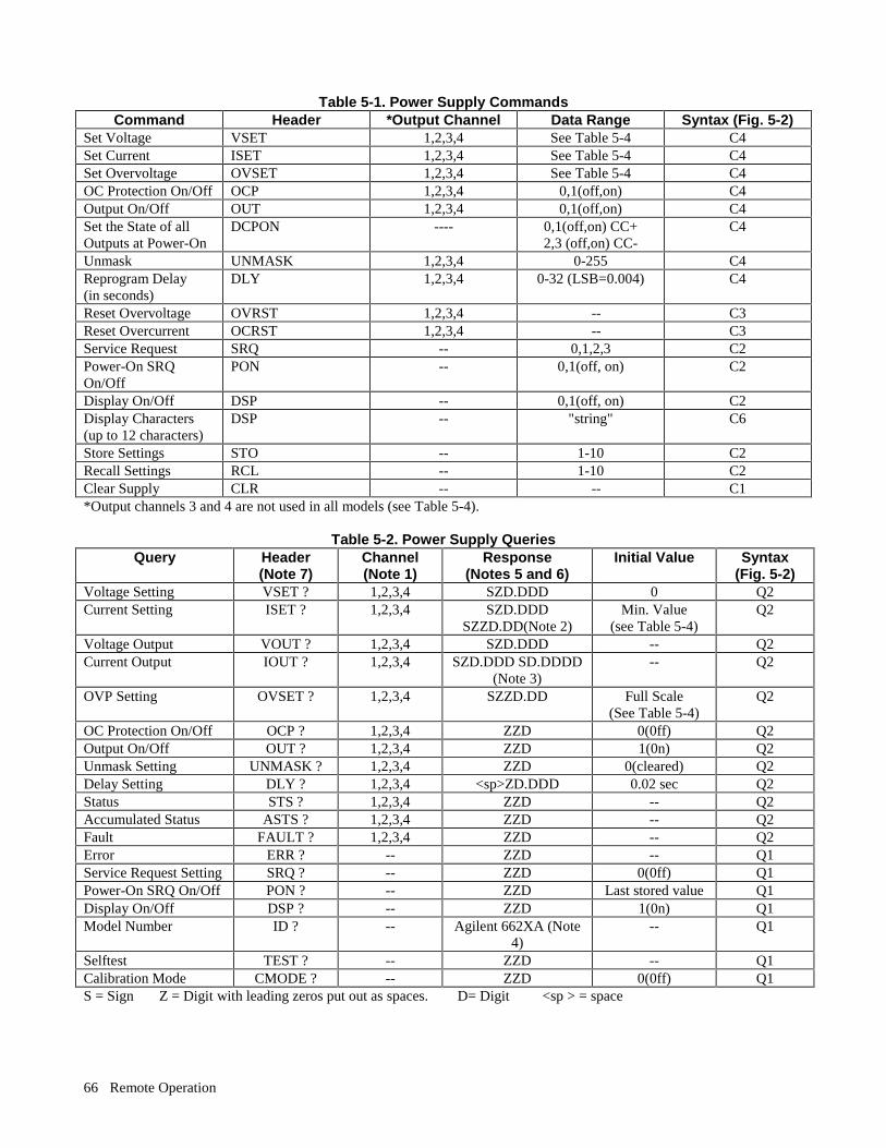
Remote Operation 66
Table 5-1. Power Supply Commands Command Header *Output Channel Data Range Syntax (Fig. 5-2)
Set Voltage VSET 1,2,3,4 See Table 5-4 C4 Set Current ISET 1,2,3,4 See Table 5-4 C4 Set Overvoltage OVSET 1,2,3,4 See Table 5-4 C4 OC Protection On/Off OCP 1,2,3,4 0,1(off,on) C4 Output On/Off OUT 1,2,3,4 0,1(off,on) C4 Set the State of allOutputs at Power-On
DCPON ---- 0,1(off,on) CC+2,3 (off,on) CC-
C4
Unmask UNMASK 1,2,3,4 0-255 C4 Reprogram Delay (in seconds)
DLY 1,2,3,4 0-32 (LSB=0.004) C4
Reset Overvoltage OVRST 1,2,3,4 -- C3 Reset Overcurrent OCRST 1,2,3,4 -- C3 Service Request SRQ -- 0,1,2,3 C2 Power-On SRQOn/Off
PON -- 0,1(off, on) C2
Display On/Off DSP -- 0,1(off, on) C2 Display Characters (up to 12 characters)
DSP -- "string" C6
Store Settings STO -- 1-10 C2 Recall Settings RCL -- 1-10 C2 Clear Supply CLR -- -- C1 *Output channels 3 and 4 are not used in all models (see Table 5-4).
Table 5-2. Power Supply Queries Query Header
(Note 7) Channel (Note 1)
Response (Notes 5 and 6)
Initial Value Syntax (Fig. 5-2)
Voltage Setting VSET ? 1,2,3,4 SZD.DDD 0 Q2 Current Setting ISET ? 1,2,3,4 SZD.DDD
SZZD.DD(Note 2) Min. Value
(see Table 5-4) Q2
Voltage Output VOUT ? 1,2,3,4 SZD.DDD -- Q2 Current Output IOUT ? 1,2,3,4 SZD.DDD SD.DDDD
(Note 3) -- Q2
OVP Setting OVSET ? 1,2,3,4 SZZD.DD Full Scale (See Table 5-4)
Q2
OC Protection On/Off OCP ? 1,2,3,4 ZZD 0(0ff) Q2 Output On/Off OUT ? 1,2,3,4 ZZD 1(0n) Q2 Unmask Setting UNMASK ? 1,2,3,4 ZZD 0(cleared) Q2 Delay Setting DLY ? 1,2,3,4 <sp>ZD.DDD 0.02 sec Q2 Status STS ? 1,2,3,4 ZZD -- Q2 Accumulated Status ASTS ? 1,2,3,4 ZZD -- Q2 Fault FAULT ? 1,2,3,4 ZZD -- Q2 Error ERR ? -- ZZD -- Q1 Service Request Setting SRQ ? -- ZZD 0(0ff) Q1 Power-On SRQ On/Off PON ? -- ZZD Last stored value Q1 Display On/Off DSP ? -- ZZD 1(0n) Q1 Model Number ID ? -- Agilent 662XA (Note
4) -- Q1
Selftest TEST ? -- ZZD -- Q1 Calibration Mode CMODE ? -- ZZD 0(0ff) Q1 S = Sign Z = Digit with leading zeros put out as spaces. D= Digit <sp > = space
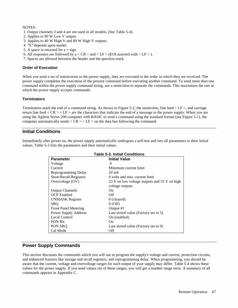
Remote Operation 67
NOTES: 1. Output channels 3 and 4 are not used in all models. (See Table 5-4). 2. Applies to 80 W Low V output. 3. Applies to 40 W High V and 80 W High V outputs. 4. ’’X’’ depends upon model. 5. A space is returned for a + sign. 6. All responses are followed by a < CR > and < LF > (EOI asserted with < LF > ). 7. Spaces are allowed between the header and the question mark. Order of Execution When you send a set of instructions to the power supply, they are executed in the order in which they are received. Thepower supply completes the execution of the present command before executing another command. To send more than onecommand within the power supply command string, use a semicolon to separate the commands. This maximizes the rate atwhich the power supply accepts commands. Terminators Terminators mark the end of a command string. As shown in Figure 5-2, the semicolon, line feed < LF >, and carriagereturn line feed < CR > < LF > are the characters that indicate the end of a message to the power supply. When you areusing the Agilent Series 200 computer with BASIC to send a command using the standard format (see Figure 5-1), thecomputer automatically sends < CR > < LF > on the data bus following the command.
Initial Conditions Immediately after power on, the power supply automatically undergoes a self-test and sets all parameters to their initialvalues. Table 5-3 lists the parameters and their initial values.
Table 5-3. Initial Conditions Parameter Initial Value Voltage 0 Current Minimum current limit Reprogramming Delay 20 mS Store/Recall Registers 0 volts and min. current limit Overvoltage (OV) 23 V on low voltage outputs and 55 V on high
voltage outputs Output Channels On OCP Enabled Off UNMASK Register 0 (cleared) SRQ 0 (Off) Front Panel Metering Output #1 Power Supply Address Last stored value (Factory set to 5) Local Control On (enabled) PON Bit On PON SRQ Last stored value (Factory set to 0) Cal Mode Off
Power Supply Commands This section discusses the commands which you will use to program the supply’s voltage and current, protection circuits,and enhanced features like storage and recall registers, and reprogramming delay. When programming, you should beaware that the current, voltage and overvoltage ranges for each output of your supply may differ. Table 5-4 shows thesevalues for the power supply. If you send values out of these ranges, you will get a number range error. A summary of allcommands appears in Appendix C.
Remote Operation 68
The output voltage of some output channels exceeds the safe operating limit of 42.2 V. To avoid anyelectrical shock, program the voltage to zero volts or turn off ac input power before changing any rearpanel connections. Make certain all straps are properly connected, terminal block screws are
securely tightened and terminal block covers are replaced before reapplying power. Voltage Programming To program voltage, send the output channel and the programmed value. In the example below, output 1 is programmed to5 V.
VSET 1,5 The values you send must always be volts. For example if you want to program 450 millivolts, convert to volts and thensend the command:
VSET 1,.45 If the output channel is operating in constant voltage mode (CV annunciator on) then the actual voltage is the programmedvoltage, but in CC mode of operation (CC annunciator on), the programmed voltage is the voltage limit for that output. To readback the programmed voltage setting for output 1, send the query:
VSET? 1 and address the supply to talk. If you want to know the value of the actual output voltage of output 1, send the query:
VOUT? 1 The results are placed on the GP-IB and read into the controller when the supply is addressed to talk.
NOTE The power supply will round the VSET and ISFT settings to the nearest multiple of their resolution.Table 5-4 lists the average resolution of these settings.
Current Programming To program the current, send the output channel and the programmed value in amps. In the example below, output isprogrammed to 1.15 amps.
ISET 1,1.15 The value you send must always be in amps. For example if you want to program 95 milliamps, convert to amps and thensend the command
ISET 1,.095 If the output channel is in constant current (CC) mode of operation, then the actual current is the programmed current but ifthe output is in the CV mode, the programmed current is the current limit of that output. To readback the programmed current for output 1, send the query and addressing the supply to talk.
ISET? 1 You can also instruct the supply to measure the actual output current at output channel 1 by sending the following queryand address the supply to talk.
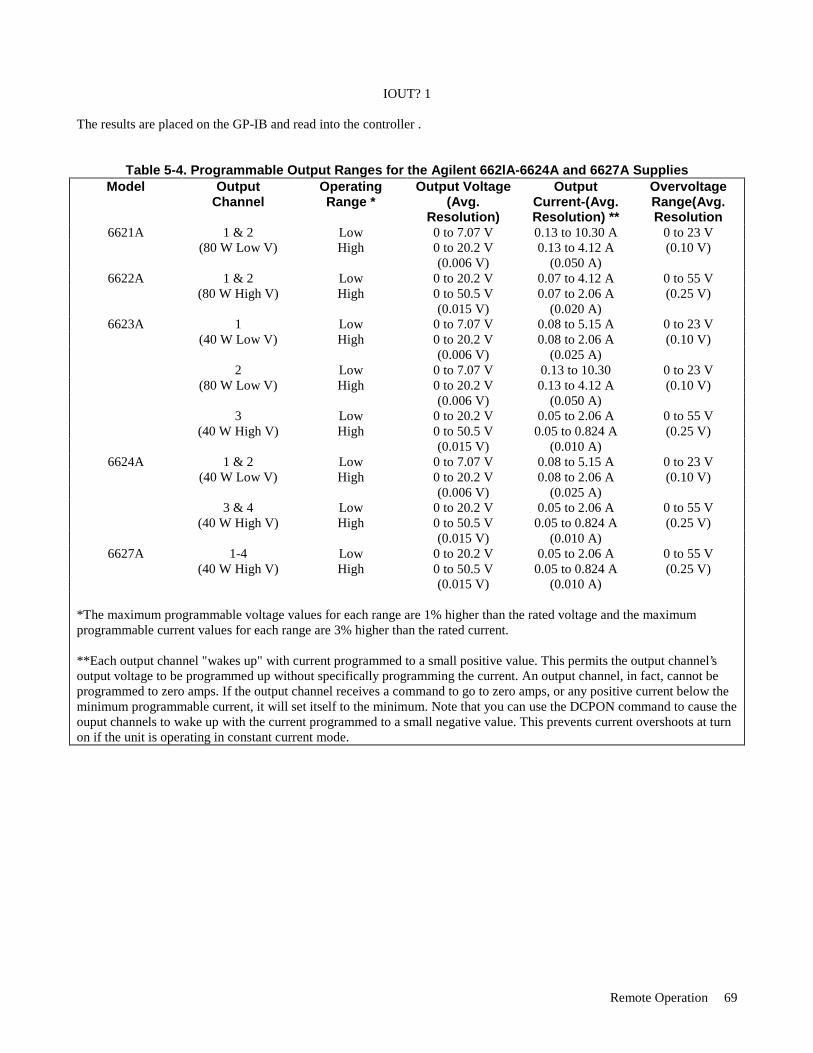
Remote Operation 69
IOUT? 1 The results are placed on the GP-IB and read into the controller .
Table 5-4. Programmable Output Ranges for the Agilent 662lA-6624A and 6627A Supplies Model Output
Channel OperatingRange *
Output Voltage(Avg.
Resolution)
OutputCurrent-(Avg.Resolution) **
OvervoltageRange(Avg.Resolution
6621A 1 & 2 Low 0 to 7.07 V 0.13 to 10.30 A 0 to 23 V (80 W Low V) High 0 to 20.2 V 0.13 to 4.12 A (0.10 V) (0.006 V) (0.050 A)
6622A 1 & 2 Low 0 to 20.2 V 0.07 to 4.12 A 0 to 55 V (80 W High V) High 0 to 50.5 V 0.07 to 2.06 A (0.25 V) (0.015 V) (0.020 A)
6623A 1 Low 0 to 7.07 V 0.08 to 5.15 A 0 to 23 V (40 W Low V) High 0 to 20.2 V 0.08 to 2.06 A (0.10 V) (0.006 V) (0.025 A) 2 Low 0 to 7.07 V 0.13 to 10.30 0 to 23 V (80 W Low V) High 0 to 20.2 V 0.13 to 4.12 A (0.10 V) (0.006 V) (0.050 A) 3 Low 0 to 20.2 V 0.05 to 2.06 A 0 to 55 V (40 W High V) High 0 to 50.5 V 0.05 to 0.824 A (0.25 V) (0.015 V) (0.010 A)
6624A 1 & 2 Low 0 to 7.07 V 0.08 to 5.15 A 0 to 23 V (40 W Low V) High 0 to 20.2 V 0.08 to 2.06 A (0.10 V) (0.006 V) (0.025 A) 3 & 4 Low 0 to 20.2 V 0.05 to 2.06 A 0 to 55 V (40 W High V) High 0 to 50.5 V 0.05 to 0.824 A (0.25 V) (0.015 V) (0.010 A)
6627A 1-4 Low 0 to 20.2 V 0.05 to 2.06 A 0 to 55 V (40 W High V) High 0 to 50.5 V 0.05 to 0.824 A (0.25 V) (0.015 V) (0.010 A)
*The maximum programmable voltage values for each range are 1% higher than the rated voltage and the maximumprogrammable current values for each range are 3% higher than the rated current. **Each output channel "wakes up" with current programmed to a small positive value. This permits the output channel’soutput voltage to be programmed up without specifically programming the current. An output channel, in fact, cannot beprogrammed to zero amps. If the output channel receives a command to go to zero amps, or any positive current below theminimum programmable current, it will set itself to the minimum. Note that you can use the DCPON command to cause theouput channels to wake up with the current programmed to a small negative value. This prevents current overshoots at turnon if the unit is operating in constant current mode.
Remote Operation 70
Range Switching Each output operates in the boundaries of either the low range or the high range as specified in Table 5-4. Refer to page 43for a detailed description of the dual range operation. The range is selected based on the programmed parameters. If the lastparameter (voltage or current) programmed is outside of the existing range, the supply will automatically switch ranges. Asequence of examples are given on the next page to illustrate this operation. Output 1, used in the examples, is a 40 W LowV output.
Example 1: VSET 1,5; ISET 1,2 This example programs output 1 to 5 V and 2 A. These values are in the quadrant of the characteristic curve which has voltage and current boundaries common to both high and low operating ranges.
Example 2: VSET 1,20
Now output 1 is in the high range programmed to 20 V and 2A.
Example 3: VSET 1,5; ISET 1,3 Output 1 is now in the low range programmed to 5 V and 3A.
Example 4: VSET 1,10
Now output 1 is in the high range and the current is automatically scaled back from 3 A to the lower current limit of 2.06 A. The output is operating in the same range as that of Example 2.
Example 5: VSET 1,20; ISET 1,3 The ISET command will cause the voltage to be scaled back to the low range limit of 7.07 V and the output will operatewithin the boundaries of the low range as in Example 3.
NOTE When the range is automatically switched, as in examples 4 and 5, the "coupled parameter’’ bit (CP) in thestatus register (see Table 5-5) is set to indicate that range switching occurred.
Output On/Off The OUT command disables/enables an output channel of the power supply. It will not disturb any other programmedfunction nor will it reset the protection circuits. You can control individual outputs with the OUT command as shownbelow. For example, to disable output channel 1 send the following:
OUT 1,0 To enable output channel 1 send the following command
OUT 1,1 You can find out the present state of output 1 by sending the query:
OUT? 1 and addressing the supply to talk. The response from the supply is either a "0" to indicate output 1 is off or a "1’’ to indicatethat the output is on. When disabled, the output behaves as if it were programmed to zero volts and minimum current.

Remote Operation 71
Overvoltage (OV) Protection The programmable OV is a protection feature which can be set by the operator to protect the load against excessive voltage.When the actual voltage exceeds the programmed overvoltage setting for a given output channel, the OV is tripped. TheOV circuit will fire the SCR crowbar which shorts across the output and the output assumes a low impedance state. For example, to program the OV of output channel 1 to 9.5 V send the following command:
OVSET 1,9.5 To find out the OV setting for output channel 1 send the following query and address the supply to talk:
OVSET? 1 To enable an output after it went into overvoltage, you must first remove the overvoltage condition and then send the OVreset command. To reset output 1 send:
OVRST 1 If you send the reset command without first removing the OV condition, the supply will fire the OV again.
NOTE If the programmable OV fails, the supply has a fixed OV circuit which will fire the SCR crowbar if thevoltage exceeds 120% of the maximum rated output. The fixed OV circuit will also fire the SCR crowbarif the supply is off (line cord disconnected) and an external source is supplying voltage which exceeds120% of the maximum rated output.
Overcurrent Protection (OCP) The OCP is a protection feature employed by the power supply to guard against excessive output currents. When the outputenters the + CC mode and the OCP is enabled, the OCP circuit down programs the output voltage and disables the output. To enable the OCP, for output channel 1, send the command
OCP 1,1 To disable the OCP, send the command
OCP 1,0 You can find out the OCP setting by sending the following query and addressing the power supply to talk.
OCP? 1 The response from the power supply is either a "0" to indicate that OCP is off or a ’’1" to indicate that it is on. To reset theoutput channel after an overcurrent trip, you can either disable the OCP and send the reset command, or you can reduce theoutput current below the programmed current and then send the reset command. To reset output 1, send the command:
OCRST 1
NOTE The supply can report a fault condition when an output is in overvoltage or overcurrent. Although theOVRST and OCRST commands reenable the output, they do not clear the fault register. As ahousekeeping measure, it is advisable to always clear the fault register by querying its value after an OVor OC reset.

Remote Operation 72
Multiple Output Storage & Recall The power supply has 10 internal registers each of which can store the voltage and current settings of all the outputs. Bystoring voltage and current settings for all outputs and recalling them later, you can have significant savings inprogramming time. (See Supplemental Characteristics in Table 1-1). At power-on, each of the registers contain 0 volts and the minimum current limit. To store voltage and current settings, youmust specify the register (1 to 10). For example to store the present settings of current and voltage of all your supply’soutputs in register 2, send the following command:
STO 2 This command will take the programmed voltage and current settings of all output channels and store them in register 2. You can set the power supply outputs to these stored voltage and current settings by sending the recall command.
RCL 2 When a register is recalled, the outputs will be set sequentially (output 1, output 2, etc.). If you attempt to recall registerswhich were not previously stored, then the supply will return the power-on values for that register (0 volts and minimumcurrent limit). If you recalled registers outside the 1 to 10 range, you will get a number range error. The Clear Command This command will return the power supply to its power-on state and all parameters are returned to their initial power-onvalues except for the following:
1. The store/recall registers are not cleared. 2. The power supply remains addressed to listen. 3. The PON bit in the serial poll register is cleared.
To Clear the power supply, send the following command:
CLR Status Reporting The power supply has the ability to report its internal status to the user whenever it is asked to do so. Depending on the typeof status the user requested, the supply will interrogate the status, accumulated status, mask, or fault registers present ineach output. The status register can report status independently or it can work together with the mask and fault registers toreport a fault. The accumulated status register records every status condition the output experienced since the time it waslast read. Figure 5-3 shows a conceptual model of the operation of these registers.
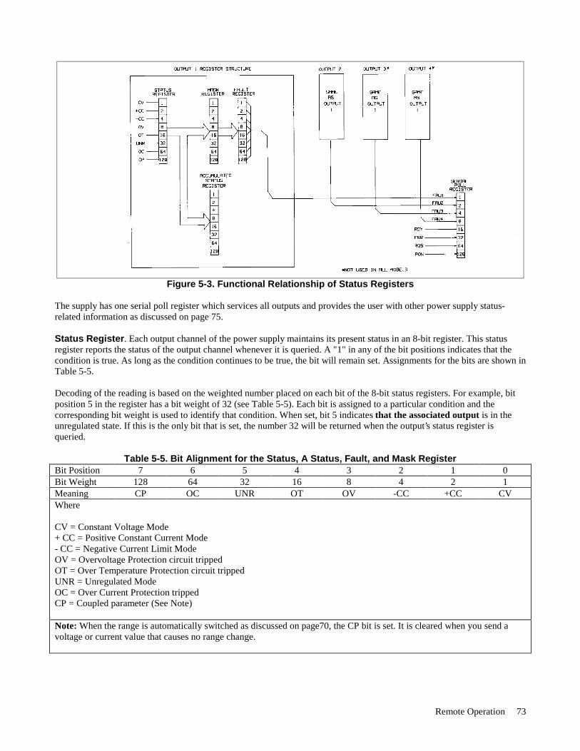
Remote Operation 73
Figure 5-3. Functional Relationship of Status Registers
The supply has one serial poll register which services all outputs and provides the user with other power supply status-related information as discussed on page 75. Status Register. Each output channel of the power supply maintains its present status in an 8-bit register. This statusregister reports the status of the output channel whenever it is queried. A "1" in any of the bit positions indicates that thecondition is true. As long as the condition continues to be true, the bit will remain set. Assignments for the bits are shown inTable 5-5. Decoding of the reading is based on the weighted number placed on each bit of the 8-bit status registers. For example, bitposition 5 in the register has a bit weight of 32 (see Table 5-5). Each bit is assigned to a particular condition and thecorresponding bit weight is used to identify that condition. When set, bit 5 indicates that the associated output is in theunregulated state. If this is the only bit that is set, the number 32 will be returned when the output’s status register isqueried.
Table 5-5. Bit Alignment for the Status, A Status, Fault, and Mask Register Bit Position 7 6 5 4 3 2 1 0 Bit Weight 128 64 32 16 8 4 2 1 Meaning CP OC UNR OT OV -CC +CC CV Where CV = Constant Voltage Mode + CC = Positive Constant Current Mode - CC = Negative Current Limit Mode OV = Overvoltage Protection circuit tripped OT = Over Temperature Protection circuit tripped UNR = Unregulated Mode OC = Over Current Protection tripped CP = Coupled parameter (See Note) Note: When the range is automatically switched as discussed on page70, the CP bit is set. It is cleared when you send avoltage or current value that causes no range change.
Remote Operation 74
To query an output channel for its status, you must specify the output channel. For example, to find out the status at output2 send the following query and address the supply to talk:
STS? 2 Accumulated Status Register. Each output channel of the power supply also maintains a cumulative status in itsaccumulated status (astatus) register. This register records every status condition the power supply output entered since itwas last queried. When queried, it returns a decimal number which is decoded as shown below. The astatus register is resetto the present value of the status register after it is queried. The bits are assigned as in Table 5-5. Here is an example to helpyou decode the decimal number (from 0 to 255) returned when the astatus register is queried. If the output channel was inovervoltage since the last reading of the astatus register and that channel is presently operating in constant voltage mode,the reading you will get when you query the register will be 9. To decode this we use table 5-5.
9 = 8 + 1 OV + CV
For example, to query the astatus register of output 2, send the following query and address the supply to talk.
ASTS? 2 The Mask and Fault Register. The fault register works in conjunction with the mask register. These are two eight bitregisters which report any fault condition on a particular output channel. The mask register is used to set up the conditionsthat generate a fault which is latched into the fault register. The user can then read the fault register to determine the fault.When a bit in the fault register is set, the power supply can generate a service request for that output providing the servicerequest command on fault (SRQ 1 or SRQ 3) was previously sent. See page 76 for a discussion on service request. To understand how these two registers work, we must include the status register in this discussion. Recall that the statusregister takes its input from the power supply and the user cannot change its contents. The mask register takes its inputsfrom the user, and the power supply cannot change its contents. The fault register takes its inputs from both the mask andthe status registers. You can find out the setting of the mask register of output 2 by sending the following query andaddressing the supply to talk:
UNMASK? 2 The response will be a numeric code between 0 and 255 which can be decoded by consulting Table 5-5. You can set theconditions to generate a fault by setting (unmasking) one or more bits in the mask register. The conditions will remainunmasked until you change them. To unmask conditions in output 2 for example, send the following command:
UNMASK 2,XXX where XXX specifies the numeric code (0 to 255) for the unmasked conditions (see Table 5-5). If during operation, theoutput experiences any of the previously unmasked conditions, it will set the corresponding bit(s) in its fault register. Remember that the bits in the fault register can be set when there is a change in either the status register or the maskregister. Each output has its status, mask, and fault registers arranged as shown in Figure 5-3 and Table 5-5. The maskregister, which is set by the user, is used to specify which bits in the status register are enabled (unmasked) to set bits in thefault register. A bit is set in the fault register when the corresponding bit in the status register changes from "0’’ to "1" andthe corresponding bit in the mask register is a "1". Also, if a bit in the status register is already set and then thecorresponding bit in the mask register is set (unmasked), the corresponding bit in the fault register will be set. In addition, if both status and mask register bits remain set after the fault register was read (and cleared), the fault registerwill remain cleared as long as there are no changes in either the status or mask registers with the following exception.Executing a VSET, ISET, RCL, OVRST, OCRST, or OUT on/off command, will cause the CV, + CC, - CC, or UNR bit(as applicable) in the fault register to be set. Note that the fault register is cleared immediately after it is read.

Remote Operation 75
As shown in Figure 5-3, if one or more bits in the fault register of a given output channel are set, then the FAU bit for thatoutput in the serial poll register will also be set and a service request may be generated (see page 76). To read the faultregister of output 2 and find out which bits are set, send the following query and address the supply to talk:
FAULT? 2 The power supply responds with a number which can be decoded from Table 5-5. For example, the number 9 (8 + 1)indicates that the OV and the CV bits in the fault register are set.
NOTE If the condition(s) generating the fault(s) is (are) removed but the fault register is not read, the bit(s) in thefault register will remain set.
The Serial Poll Register. The serial poll register is an 8 bit register which the supply uses to keep track of its internaloperating status and to determine the operating status of each of its outputs. Table 5-6 defines each bit.
Table 5-6. Bit Assignment of the Serial Poll Register Bit Position 7 6 5 4 3 2 1 0 Bit Weight 128 64 32 16 8 4 2 1 Meaning PON RQS ERR RDY FAU 4 FAU 3 FAU 2 FAU 1 The first four bits (0 to 3) in the register tell whether or not a particular output has a fault. If there is a fault in one of theoutputs, then the corresponding FAU bit will be set. Thus if output 1 has a fault, then FAU 1 will be set. In models withonly three outputs, FAU 4 will always be zero and in two output models, FAU 3 and FAU 4 will always be zero. The RDY bit is set when processing is complete and is cleared when the supply is processing commands. The ERR bit is set when a programming or hardware error occurs and is cleared when the error query (ERR?) is received.The error annunciator on the front panel informs the user when this bit is set or cleared. The RQS bit is set when the power supply generates a service request and cleared after a serial poll is done (see thefollowing paragraph, Service Request Generation). The PON bit is set at power on and cleared when a CLR command is sent. Service Request Generation When operating your supply, you may want it to request service every time a fault or a programming error conditionoccurs. To do this you send a service request (SRQ) command. When the condition is true, the power supply responds bysetting the RQS bit in the serial poll register, setting the SRQ annunciator on the front panel, and issuing an SRQ over theGP-IB. The 662xA supplies can generate a service request for any of the following reasons: (refer to Table 5-7). • An Output Fault. If there is a fault on one or more of the output channels and you previously sent the SRQ 1 or
SRQ 3 command (see Service Request Enable/Disable information below), then an SRQ will be generated. • An Error. If there is an error (see Tables 5-8) and you previously sent the SRQ 2 or SRQ 3 command, (see Service
Request Enable/Disable information below), then the supply will generate a service request. • Power-on. At power-on, the PON bit of the serial poll register is set but the supply will only generate an SRQ if you
previously sent a PON 1 command. • Input Line Voltage Dropout. Same as power-on condition.
Remote Operation 76
To find out the nature of the service request, you must do a serial poll. This will isolate the output that generated the requestby checking which of the FAU bits are set in the case of a fault, or checking to see if the error bit is set in the case of anerror. If the SRQ on faults was set, then send the fault query.
FAULT? 2 (using output 2 as an example) and address the supply to talk if you want to find out which of the conditions you unmasked in Figure 5-3 are true. Forexample if the supply was in overvoltage and that condition was unmasked then the response from the fault query will be’’8" (see Table 5-5).
NOTE When you query the fault, the fault register is cleared. Performing a serial poll will reset the PQS bit butwill not clear the fault register.
If the SRQ on error was set, then you can send the error query ERR? and address the supply to talk. The response willidentify the error by its code (see Table 5-8). Service Request Enable/Disable. You can query the status of the service request enable/disable function by sendingthe query:
SRQ? and addressing the power supply to talk. The response from the supply is one of the following:
0, 1, 2, or 3
0--indicates that the service request capability (except for power-on; see The Power On-Service Request information below) is disabled. 1--indicates that it is enabled for output fault conditions. 2--indicates that it is enabled for error conditions. 3--indicates that it is enabled for both fault and error conditions
The ability to generate service requests can be enabled or disabled using the SRQ command as described below. To disable the service request capability, except for power-on, send:
SRQ 0 To enable the service request capability for all output faults,
SRQ 1 To enable the service request capability for errors, send:
SRQ 2 To enable the service request capability for both faults and errors, send:
SRQ 3 The Power-On Service Request. You can also cause the power supply to request service every time it is switched onor every time there is a temporary loss in power. To do this send the following command:
PON 1

Remote Operation 77
If you want to disable this facility, send the command.
PON 0 If you want to find out if the power-on SRQ is enabled or disabled, send the following query:
PON ? and address the supply to talk. The supply will respond with a 1 or 0 as discussed above.
NOTE The power-on (PON) SRQ mode is stored in the non-volatile memory of the supply so that although thesupply may be switched off, it will remember the status of the last PON command at power-on andrespond accordingly.
Table 5-7 summarizes all the conditions under which a service request will be generated.
Table 5-7 Condition for Generating a Service Request Condition Commands Sent State of
PON SRQ RQS Bit • Any 0 0 0 • Power-on 1 - 1 • Error - 2 or 3 1 • Fault - 1 or 3 1
Reprogramming Delay
The power supply may switch modes or become unregulated momentarily after a new output value is programmed.Because of their short duration, these cases may not ordinarily be considered a fault but the supply will recognize thisdeviation and generate a fault signal. To prevent this, the reprogramming delay feature is implemented.
Reprogramming delay will delay the onset of certain fault conditions and prevent the power supply from registering a faultwhen these conditions are true. When the delay is in effect, the CV, + CC, - CC and UNR bits of the status register aremasked and cannot communicate with the mask and fault registers and the OCP function. This will prevent the supply fromregistering a fault should any of these bits become set during the delay period. Reprogramming delay is initiated when anyof the following functions are executed:
VSET: ISET: RCL: OVRST: OCRST; OUT on/off
At power-on reprogramming delay is set to 20 mS. You can specify new values between 0 and 32 S in steps of 4 mS. If youspecify a value which is not a multiple of 4 mS, the supply will round off the set value to the nearest 4 mS multiple.
To program a new value of 80 mS in output 2 for example, send the following:
DLY 2,.08
If you send a value outside the 0 to 32 S range you will get a programming error. You may use the programming responsetimes in the specifications table to give you an idea of a typical delay setting. However, the appropriate delay setting willalso depend on load capacitance, load resistance, and current limit setting. See page 51 for output capacitor considerations.
To query the reprogramming delay setting of a particular output channel, send the following query:
DLY? 2 (using output 2 as an example)

Remote Operation 78
and address the supply to talk. The response will be a numeric value between 0 and 32.
Display On/Off
When the display is on, the commands sent across the GP-IB may experience a slower processing time because theprocessor must also spend time to monitor the outputs and update the display. You can shorten your command processingtime by turning off the display. To turn off the display, send the command:
DSP 0
To re-enable the display send the command:
DSP 1
You can also find out the status of the display by sending the following query and addressing the supply to talk:
DSP?
The response will be either a "1’’ or a "0’’.
Message Display Capability. The display command can also be used to display messages on the front panel. Messagesmay consist of a maximum of twelve alphanumeric characters. Only upper case alpha characters, numbers, and spaces willbe displayed.
For example, to display the message "OUTPUT 2 OK” send the following command:
DSP "OUTPUT 2 OK"
NOTE The BASIC programming statement for a series 200/300 computer would be as follows:
OUTPUT 705; ''DSP'"'OUTPUT 2 OK""
Other Queries
In the examples discussed above, you saw how to use queries for each function discussed. The following paragraphsdescribe other queries which were not previously covered.
ERROR Query. The power supply can detect both programming and hardware errors. You can use either the front panel(see page 87) or the GP-IB to find out the type of error. Upon detecting an error, the error annunciator on the front paneland the ERR bit in the serial poll register will be set. When in local mode the supply will display the error name in responseto pressing the ERR key on the front panel. Over the GP-IB, only the error code will be returned. After a query, the error bitis cleared. A description of these codes is given in Table 5-8. To find out what the error is, send the following query andaddress the supply to talk:
ERR?
The supply will respond with an error code number (see Table 5-8).
ID Query. If you want to know the model number of the power supply you are working with, you can send the ID? queryover the GP-IB. To do this send the following over the GP-IB and address the supply to talk.
ID?The supply will respond with its model number.
Test Query. You can get the power supply to perform a limited self-test at any time during its operation by sending theTEST? query over the GP-IB. This test does not affect the analog control circuits of the supply and it can be performedwhile the outputs are connected to external circuits. For tests of the analog control circuits refer to Chapter 3. Responses to
Remote Operation 79
the test query are described in Table 5-9. This test cannot be done from the front panel. To instruct the power supply tocarry out a self-test, send the following query and address the supply to talk:
TEST?
Calibration Mode Query. To be able to calibrate your power supply, the calibration mode (CMODE) must be turned on(See Appendix A for a detailed description of the calibration procedure). To find out if the CMODE is on or off, send thefollowing query over the GP-IB and address the supply to talk:
CMODE?
The supply will respond with a ’’1" which indicates that CMODE is on or a "0" which indicates that CMODE is off.
DCPON. The DCPON command sets the state of all outputs at power-on. You can specify if the outputs wake up enabledor disabled when the unit is turned on. To enable all outputs at turn-on send:
DCPON 1
To disable all outputs at turn-on send:DCPON 0
Note that these commands set the output voltage to zero and the output current to a slightly positive value when theOUTPUT OFF command is issued. Therefore, the constant voltage feedback loop is active and the outputs are in constantvoltage mode when programmed “OFF”.
Starting with firmware revision A.00.04 and later, two additional commands let you set the output current to a slightlynegative value when the OUPUT OFF command is issued, causing the outputs to be in constant current mode whenprogrammed “OFF”. The benefit of being in constant current mode when the output is off is that if the load impedance andthe voltage and current settings are such that the unit is forced into constant current mode at turn on, then the currentfeedback loop will be active during the transition to OUTPUT ON, and there will be no output current overshoot due tomode crossover.
To enable all outputs in constant current mode at turn on send: DCPON 2
To disable all outputs in constant current mode at turn-on send: DCPON 3
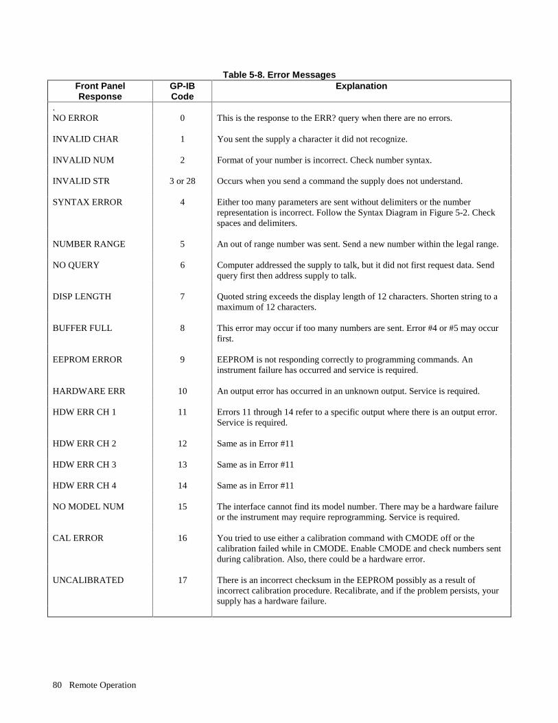
Remote Operation 80
Table 5-8. Error MessagesFront PanelResponse
GP-IBCode
Explanation
.NO ERROR 0 This is the response to the ERR? query when there are no errors.
INVALID CHAR 1 You sent the supply a character it did not recognize.
INVALID NUM 2 Format of your number is incorrect. Check number syntax.
INVALID STR 3 or 28 Occurs when you send a command the supply does not understand.
SYNTAX ERROR 4 Either too many parameters are sent without delimiters or the numberrepresentation is incorrect. Follow the Syntax Diagram in Figure 5-2. Checkspaces and delimiters.
NUMBER RANGE 5 An out of range number was sent. Send a new number within the legal range.
NO QUERY 6 Computer addressed the supply to talk, but it did not first request data. Sendquery first then address supply to talk.
DISP LENGTH 7 Quoted string exceeds the display length of 12 characters. Shorten string to amaximum of 12 characters.
BUFFER FULL 8 This error may occur if too many numbers are sent. Error #4 or #5 may occurfirst.
EEPROM ERROR 9 EEPROM is not responding correctly to programming commands. Aninstrument failure has occurred and service is required.
HARDWARE ERR 10 An output error has occurred in an unknown output. Service is required.
HDW ERR CH 1 11 Errors 11 through 14 refer to a specific output where there is an output error.Service is required.
HDW ERR CH 2 12 Same as in Error #11
HDW ERR CH 3 13 Same as in Error #11
HDW ERR CH 4 14 Same as in Error #11
NO MODEL NUM 15 The interface cannot find its model number. There may be a hardware failureor the instrument may require reprogramming. Service is required.
CAL ERROR 16 You tried to use either a calibration command with CMODE off or thecalibration failed while in CMODE. Enable CMODE and check numbers sentduring calibration. Also, there could be a hardware error.
UNCALIBRATED 17 There is an incorrect checksum in the EEPROM possibly as a result ofincorrect calibration procedure. Recalibrate, and if the problem persists, yoursupply has a hardware failure.
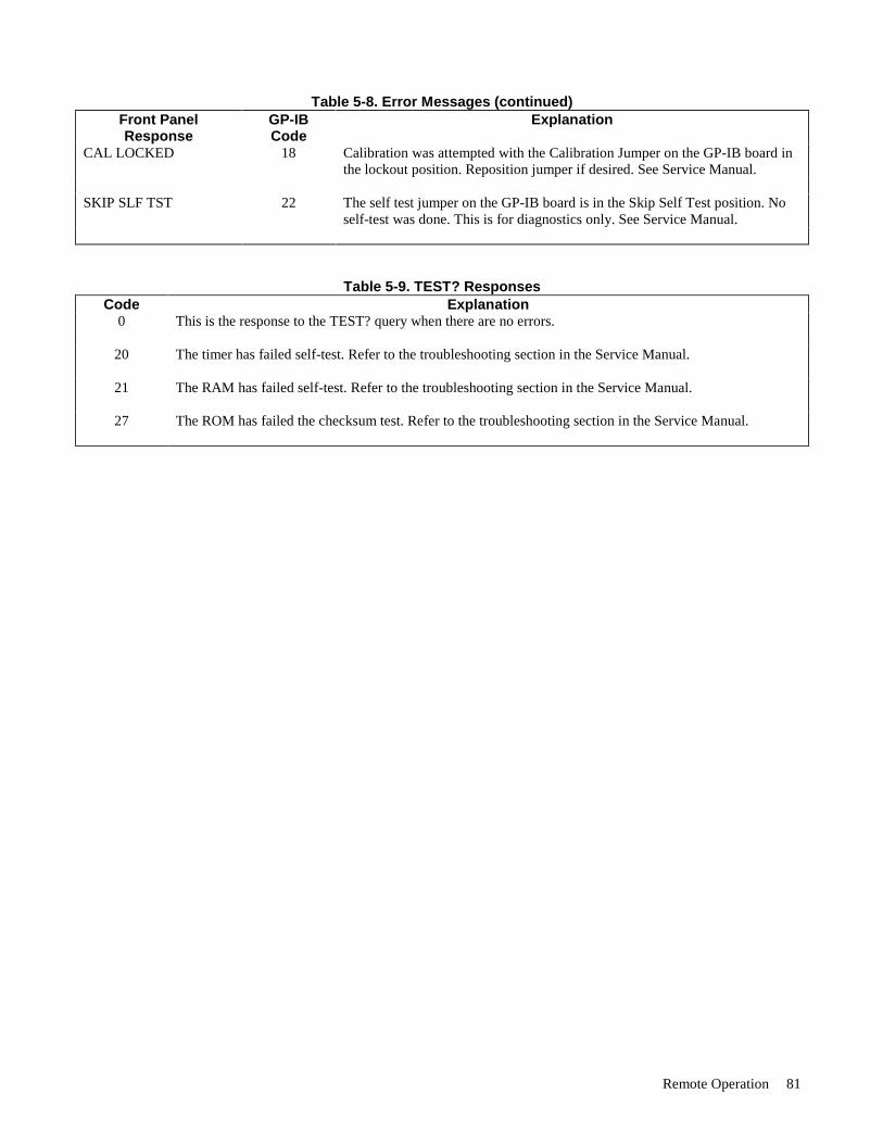
Remote Operation 81
Table 5-8. Error Messages (continued)Front PanelResponse
GP-IBCode
Explanation
CAL LOCKED 18 Calibration was attempted with the Calibration Jumper on the GP-IB board inthe lockout position. Reposition jumper if desired. See Service Manual.
SKIP SLF TST 22 The self test jumper on the GP-IB board is in the Skip Self Test position. Noself-test was done. This is for diagnostics only. See Service Manual.
Table 5-9. TEST? ResponsesCode Explanation
0 This is the response to the TEST? query when there are no errors.
20 The timer has failed self-test. Refer to the troubleshooting section in the Service Manual.
21 The RAM has failed self-test. Refer to the troubleshooting section in the Service Manual.
27 The ROM has failed the checksum test. Refer to the troubleshooting section in the Service Manual.

Local Operation 83
6Local Operation
Introduction
Chapter 3 introduced you to the supply’s front panel controls and indicators to help you turn on the supply and perform thecheckout procedures that were given in that chapter. The following paragraphs describe how to use all of the front panelcontrols and indicators. Most of the remote operations described in Chapter 5 can also be performed locally from thesupply’s front panel.
Local Mode
In order to use the front panel keys to control the supply, the local mode must be in effect. The local mode is in effectimmediately after power is applied. Table 5-3 lists the initial settings for all of the power supply’s functions when power isinitially applied. When the local mode is in effect (RMT annunciator off), the Output Function, System Function, andNumeric Entry keys on the front panel (see Figure 6-1) can be used to operate the power supply.
In the remote mode (front panel RMT annunciator on), the front panel keys will have no effect on any of the supply’soutputs and only the computer can control the supply. You can, however, still use the front panel display to view the outputvoltage and current readings or the present settings for the selected output channel while the supply is in the remote mode.
You can return the supply to the local mode from the remote mode by pressing the LCL key provided that the local lockoutcommand has not been received from the GP-IB controller. Pressing the LCL key will also turn the supply’s display backon if it was turned off with a DSP command during remote operation (see page 78). A change between the local and remotemodes will not result in a change in the power supply’s outputs.
Local Control Of Output Functions
The Output Function keys (see Figure 6-1) allow you to control the selected output. Figure 6-1 shows the annunciator arrowover OUTPUT 2 indicating that output channel 2 is selected. Pressing the OUTPUT SELECT key selects the outputchannels in forward (Ï) or reverse ( Ð ) sequence. Note that Figure 6-1 illustrates the front panel for the Agilent 6624Asupply which has four output annunciators. The Agilent 6627A front panel also has four annunciators. The front panels forAgilent Models 6621A, 6622A, and 6623A are identical to Figure 6-1 except they have fewer output annunciators.
General
The power supply will accept programming values directly in volts and amps. The programmable voltage, current, andovervoltage ranges for the outputs of each model are given in Table 5-4. The power supply will round off the valuesreceived to the nearest multiple of the resolution for that particular output. If you send a value out of the valid range, it willnot be executed and the ERR annunciator will come on. You can get a readout of the error on the display by pressing theERR key. For an out-of-range error, the error message "NUMBER RANGE" will be displayed.
When you press the VSET, ISET, OVSET, DLY, or UNMASK key, the output selected and the present setting for thatfunction will be displayed. For example, the front panel display in Figure 6-1 shows the VSET function for output 2 set to1.250. You can change the setting using the numeric entry keys. Pressing the number keys will cause the present numericsetting to become blank and be replaced with the new numbers on the display. You can use the ← key to erase previouskeystrokes if you make a mistake.
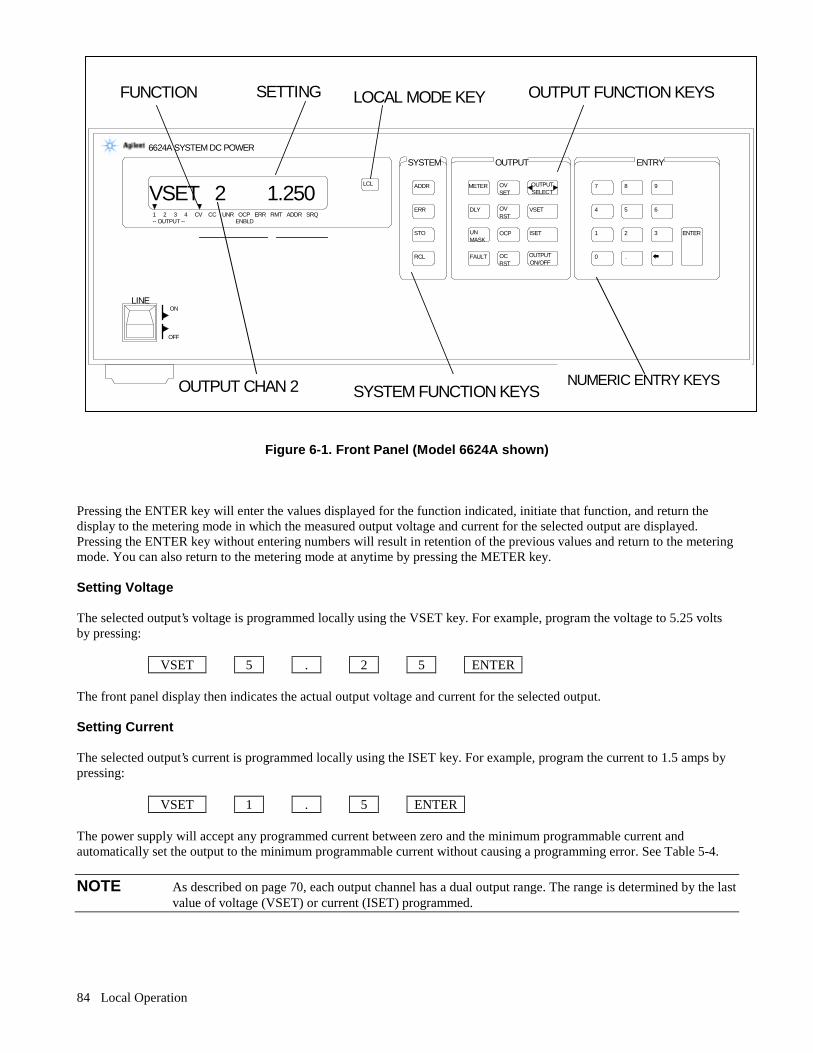
Local Operation84
Figure 6-1. Front Panel (Model 6624A shown)
Pressing the ENTER key will enter the values displayed for the function indicated, initiate that function, and return thedisplay to the metering mode in which the measured output voltage and current for the selected output are displayed.Pressing the ENTER key without entering numbers will result in retention of the previous values and return to the meteringmode. You can also return to the metering mode at anytime by pressing the METER key.
Setting Voltage
The selected output’s voltage is programmed locally using the VSET key. For example, program the voltage to 5.25 voltsby pressing:
VSET 5 . 2 5 ENTER
The front panel display then indicates the actual output voltage and current for the selected output.
Setting Current
The selected output’s current is programmed locally using the ISET key. For example, program the current to 1.5 amps bypressing:
VSET 1 . 5 ENTER
The power supply will accept any programmed current between zero and the minimum programmable current andautomatically set the output to the minimum programmable current without causing a programming error. See Table 5-4.
NOTE As described on page 70, each output channel has a dual output range. The range is determined by the lastvalue of voltage (VSET) or current (ISET) programmed.
SYSTEM OUTPUT ENTRY
LINEON
OFF
LCL ADDR
ERR
STO
RCL
METER
DLY
FAULT
UN MASK
OCP
OUTPUTSELECT
VSET
ISET
OUTPUTON/OFF
ENTER
7 8 9
4 5 6
1 2 3
0 .
6624A SYSTEM DC POWER
1 2 3 4 CV CC UNR OCP ERR RMT ADDR SRQ ENBLD-- OUTPUT --
VSET 2 1.250 OV SET
OV RST
OC RST
OUTPUT CHAN 2
OUTPUT FUNCTION KEYSFUNCTION SETTING LOCAL MODE KEY
SYSTEM FUNCTION KEYSNUMERIC ENTRY KEYS

Local Operation 85
Enabling/Disabling an Output
The selected output channel can be turned on and off from the front panel. The OUTPUT ON/OFF key toggles the selectedoutput on and off. When an output is turned off, the message ’’DISABLED" will be displayed.
The OUTPUT ON/OFF key will not affect any other programmed functions nor will it reset an overvoltage or overcurrentcondition. An output disabled by the OUTPUT ON/OFF key will behave as if it were programmed to zero volts andminimum current.
Setting Overvoltage Protection
Programmable overvoltage protection (OVP) guards your load against overvoltage by crowbarring and downprogrammingthe power supply output if the programmed overvoltage setting is exceeded.
A fixed OVP circuit with a trip level about 20 percent above the maximum programmable voltage acts as a backup to theprogrammable OVP. When overvoltage protection is activated, the output is shorted and the message ’’OVERVOLTAGE"will appear on the front panel display.
The selected output’s overvoltage setting is programmed locally using the OVSET key. For example, program theovervoltage to 10.5 volts by pressing:
OVSET 1 0 . 5 ENTER
Resetting Overvoltage Protection
The condition that caused the OV must first be cleared and then the output can be returned to its previous state by pressingthe OVRST key.
Enabling/Disabling Overcurrent Protection
The overcurrent protection feature guards against excessive output currents. When the output goes into the + CC mode andOCP is enabled, the OCP circuit is activated which downprograms the output voltage and disables the output. For thiscondition, the message ’’OVERCURRENT’’ appears on the front panel display.
The selected output’s overcurrent protection feature can be turned on and off from the front panel. The OCP key toggles theselected output’s overcurrent protection circuit on and off. When it is on (enabled), the OCP ENBLD annunciator will beon.
Resetting Overcurrent Protection
The condition that activated the OCP circuit must first be cleared then the output can be returned to its previous state bypressing the OCRST key.
Displaying the Contents of the Fault Register
Each output channel has a fault register which can be used in conjunction with the status and mask registers to report a faultcondition. A detailed description of these registers is given in Chapter 5. The main points of this description are repeatedbelow for continuity in explaining how to use the front panel UNMASK and FAULT keys.
The mask register, which is set by the user, is used to specify which bits in the status register are enabled (unmasked) to setbits in the fault register. A bit is set in the fault register when the corresponding bit in the status register changes from 0 to 1and the corresponding bit in the mask register is 1. Each output channel has its status, mask, and fault registers arranged asshown in Table 6-1.
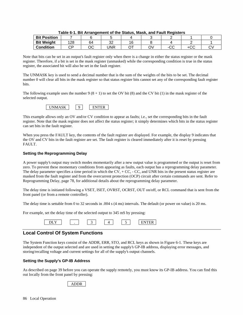
Local Operation86
Table 6-1. Bit Arrangement of the Status, Mask, and Fault RegistersBit Position 7 6 5 4 3 2 1 0Bit Weight 128 64 32 16 8 4 2 1Condition CP OC UNR OT OV -CC +CC CV
Note that bits can be set in an output’s fault register only when there is a change in either the status register or the maskregister. Therefore, if a bit is set in the mask register (unmasked) while the corresponding condition is true in the statusregister, the associated bit will also be set in the fault register.
The UNMASK key is used to send a decimal number that is the sum of the weights of the bits to be set. The decimalnumber 0 will clear all bits in the mask register so that status register bits cannot set any of the corresponding fault registerbits.
The following example uses the number 9 (8 + 1) to set the OV bit (8) and the CV bit (1) in the mask register of theselected output.
UNMASK 9 ENTER
This example allows only an OV and/or CV condition to appear as faults; i.e., set the corresponding bits in the faultregister. Note that the mask register does not affect the status register; it simply determines which bits in the status registercan set bits in the fault register.
When you press the FAULT key, the contents of the fault register are displayed. For example, the display 9 indicates thatthe OV and CV bits in the fault register are set. The fault register is cleared immediately after it is reset by pressingFAULT.
Setting the Reprogramming Delay
A power supply’s output may switch modes momentarily after a new output value is programmed or the output is reset fromzero. To prevent these momentary conditions from appearing as faults, each output has a reprogramming delay parameter.The delay parameter specifies a time period in which the CV, + CC, - CC, and UNR bits in the present status register aremasked from the fault register and from the overcurrent protection (OCP) circuit after certain commands are sent. Refer toReprogramming Delay, page 78, for additional details about the reprogramming delay parameter.
The delay time is initiated following a VSET, ISET, OVRST, OCRST, OUT on/off, or RCL command that is sent from thefront panel (or from a remote controller).
The delay time is settable from 0 to 32 seconds in .004 s (4 ms) intervals. The default (or power on value) is 20 ms.
For example, set the delay time of the selected output to 345 mS by pressing:
DLY . 3 4 5 ENTER
Local Control Of System Functions
The System Function keys consist of the ADDR, ERR, STO, and RCL keys as shown in Figure 6-1. These keys areindependent of the output selected and are used in setting the supply’s GP-IB address, displaying error messages, andstoring/recalling voltage and current settings for all of the supply’s output channels.
Setting the Supply’s GP-IB Address
As described on page 39 before you can operate the supply remotely, you must know its GP-IB address. You can find thisout locally from the front panel by pressing:
ADDR
Local Operation 87
The supply’s present address will appear in the display. Address 5 is the factory set address.
If you want to leave the address set at 5, you can return to the metering mode by pressing the METER key or you can pressanother function key.
If you want to change the address, you can enter a new value.
Any integer from 0 through 30 can be selected.
For example, you can change the address of your supply to 10 by pressing:
ADDR 1 0 ENTER
Displaying Error Messages
The power supply can detect both programming and hardware errors. Upon detecting an error, the ERR annunciator on thefront panel comes on and the ERR bit in the serial poll register will be set (see page 75).
When an error is detected, you can display the error message by pressing the ERR key. The power supply will return theerror message to the display and clear the error bit. For example, if you program a number that is not within the valid range,the ERR annunciator will come on. You can display the error message by pressing the ERR key. In this case, the errormessage "NUMBER RANGE" will be displayed. Errors generated either locally from the front panel or remotely from theGP-IB computer can be displayed by pressing the ERR key only when the supply is in the local mode. Pressing the ERRkey also clears the error bit so if you press ERR again, the message "NO ERROR" will appear. All error codes andassociated display messages are listed in Table 5-8.
Storing and Recalling Voltage and Current Settings for All Outputs
As described on page 72, the power supply has 10 internal registers for storing voltage and current settings ofall outputs. At power on each location contains zero volts and the minimum current limit (see Initial Conditions, page 68).
The STO and RCL keys allow you to store and recall voltage and current settings for all your output channels from any ofthe 10 internal registers (numbered 1 through 10). For example, you can store the present settings of voltage and current forall the output channels in internal register 2 by pressing:
STO 2 ENTER
You can change the settings of any of your supply’s outputs any number of times as required and then program them to thesettings stored in internal register 2 by pressing;
RCL 2 ENTER
The internal register will not retain the settings when power is turned off. When power is turned off and then on again, eachinternal register will be reset to the zero voltage and minimum current settings of each output channel.
The advantages in using the internal registers are that command processing time is saved and repetitive programming ofdifferent settings is simplified. The STO key can be used in conjunction with the OUTPUT ON/OFF key to store settingswhile the outputs are disabled (OFF). These stored settings can be used later to program the outputs to the stored settingsusing the RCL and OUTPUT ON/OFF keys.

Calibration Procedures 89
ACalibration Procedures
Introduction
This appendix discusses the software calibration procedures for the power supply. These supplies should be calibratedannually or whenever certain repairs are made (see Service Manual).
Because there are no internal or external hardware adjustments, your power supply can be calibrated without removing thecovers or removing it from the cabinet if it is rack mounted. Calibration is performed by measuring actual output values andsending them to the supply over the GP-IB. The power supply uses these values to calculate output, readback, andovervoltage correction constants. These correction constants are stored in a non-volatile memory on the GP-IB interfaceboard of the supply. Thereafter, when a command such as ’’VSET1,5" is sent to set the voltage on output 1, the powersupply uses the correction constants to accurately program the output.
Correction constants for offset and full scale voltage and current values are stored for one output channel at a time. Aseparate calibration command calculates and stores correction constants for the internal overvoltage circuit. This appendixlists the equipment that you need, shows the test setup to perform the calibration, gives a general calibration procedure thatexplains all of the calibration commands, and gives a sample program you can use if you have an Agilent 3456A voltmeterand an HP Series 200/300 computer with BASIC.
Security against accidental calibration is available. A jumper inside the unit may be moved to disable all calibrationcommands. Access to this jumper requires opening the unit (see the Service Manual).
Tables A-1 and A-2 give the data ranges for all of the power supply calibration commands. Refer to Figure 5-2 for thesyntax structure of the calibration commands. You can either execute the calibration commands directly from the keyboard,or you can use them in a program to reduce the time involved in calibrating each output.
NOTE The memory used to store correction constants will accept and store data about 10,000 times, which ismore than sufficient for normal calibrations over the life of the instrument. However, do not put the unitin a calibration loop that repeatedly turns the calibration mode on and off.
Test Equipment and Setup Required
The following test equipment is required for calibration:
1. A computer connected to the GP-IB connector on the back of the power supply.
2. A voltmeter accurate to 0.003% of reading.
3. A precision 0.1 Ω, ± 0.05%, 10 amp shunt resistor (4 terminal).
Figure A-1 shows the setup required for calibrating both voltage and current. Observe polarity when connecting thevoltmeter. Note that for voltage calibration, the voltmeter leads are connected to the + S and - S terminals and NOTthe + V and - V terminals. Note that for both + and - current calibration the voltmeter leads are connected to the shuntresistor’s sense terminals.
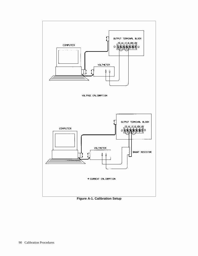
Calibration Procedures90
Figure A-1. Calibration Setup
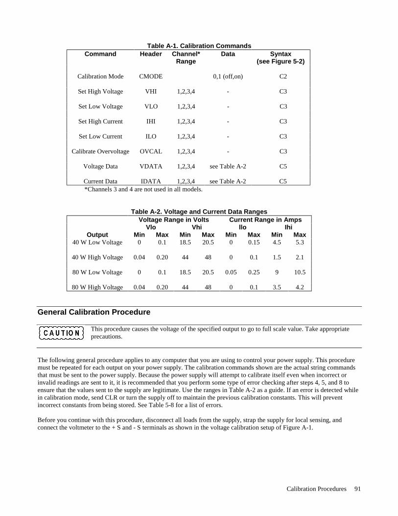
Calibration Procedures 91
Table A-1. Calibration CommandsCommand Header Channel*
RangeData Syntax
(see Figure 5-2)
Calibration Mode CMODE 0,1 (off,on) C2
Set High Voltage VHI 1,2,3,4 - C3
Set Low Voltage VLO 1,2,3,4 - C3
Set High Current IHI 1,2,3,4 - C3
Set Low Current ILO 1,2,3,4 - C3
Calibrate Overvoltage OVCAL 1,2,3,4 - C3
Voltage Data VDATA 1,2,3,4 see Table A-2 C5
Current Data IDATA 1,2,3,4 see Table A-2 C5*Channels 3 and 4 are not used in all models.
Table A-2. Voltage and Current Data RangesVoltage Range in Volts Current Range in Amps
Vlo Vhi llo IhiOutput Min Max Min Max Min Max Min Max
40 W Low Voltage 0 0.1 18.5 20.5 0 0.15 4.5 5.3
40 W High Voltage 0.04 0.20 44 48 0 0.1 1.5 2.1
80 W Low Voltage 0 0.1 18.5 20.5 0.05 0.25 9 10.5
80 W High Voltage 0.04 0.20 44 48 0 0.1 3.5 4.2
General Calibration Procedure
This procedure causes the voltage of the specified output to go to full scale value. Take appropriateprecautions.
The following general procedure applies to any computer that you are using to control your power supply. This proceduremust be repeated for each output on your power supply. The calibration commands shown are the actual string commandsthat must be sent to the power supply. Because the power supply will attempt to calibrate itself even when incorrect orinvalid readings are sent to it, it is recommended that you perform some type of error checking after steps 4, 5, and 8 toensure that the values sent to the supply are legitimate. Use the ranges in Table A-2 as a guide. If an error is detected whilein calibration mode, send CLR or turn the supply off to maintain the previous calibration constants. This will preventincorrect constants from being stored. See Table 5-8 for a list of errors.
Before you continue with this procedure, disconnect all loads from the supply, strap the supply for local sensing, andconnect the voltmeter to the + S and - S terminals as shown in the voltage calibration setup of Figure A-1.
Calibration Procedures92
Start with output channel 1 and use the following commands to calibrate your power supply:
NOTE Do not turn the power supply off during the calibration procedures. Otherwise, the correction constantsare not stored. Exercise care when moving the leads.
1. CMODE < param > - This command turns the calibration mode either on or off. The parameter must be either a 1or a 0. CMODE1 is used in the beginning of the calibration procedure to turn calibration mode on. CMODE mustbe on to use any of the calibration statements. CMODE0 is used at the end of the procedure to store the correctionconstants and turn calibration mode off. The CMODE? query can also be used at any time to determine if thesupply is in calibration mode. A 1 indicates calibration mode is on; a 0 indicates calibration mode is off. Continueto the next command.
2. VHl<channel> - This command causes the voltage of the specified output channel to go to the high calibrationpoint (full scale). After the command is sent, use the voltmeter to read the actual voltage <Vhi > put out by thepower supply. Continue to the next command.
3. VLO < channel > - This command causes the voltage of the specified output channel to go to the low calibrationpoint (voltage offset). After the command is sent, use the voltmeter to read the actual voltage < Vlo > put out bythe power supply. Continue to the next command.
4. VDATA < channel >, < Vlo >, < Vhi > - This command is used to send the actual values measured by thevoltmeter in the previous steps to the power supply. Refer to Table A-2 for the range of valid voltage readings thatcan be sent to the supply. <Vlo> is the voltage in volts that was measured after the VLO command was sent. < Vhi> is the voltage in volts that was measured after the VHI command was sent. The power supply uses these valuesto calculate the voltage and voltage readback correction constants of the specified output. Continue to the nextcommand.
5. OVCAL < channel > - This command automatically calibrates the programmable overvoltage. This can only bedone after the voltage has been calibrated. It may take up to 10 seconds for this command to execute. During thistime, the front panel display indicates "CALIBRATING" .
When the front panel display of the power supply no longer indicates ’’CALIBRATING", the overvoltage portion of thecalibration procedure is complete. The voltages on the output are returned to zero volts after the overvoltage calibration. Tocontinue with the current portion of the calibration procedure, connect a four terminal 0.1Ω current shunt resistor (0.05%,10 A) between the +V and -V output terminals. Connect the voltmeter to the resistor’s sense terminals. Refer to the currentcalibration setup in Figure A-1.
Continue calibrating output 1 with the following commands:
6. IHI < channel > - This command causes the current of the specified output channel to go to the high calibrationpoint (full scale). After the command is sent, use the voltmeter to read the voltage drop across the current shuntresistor. Divide this reading by the shunt value to derive the actual current in amps < Ihi > put out by the supply.Continue to the next command.
7. ILO <channel> - This command causes the current of the specified output channel to go to the low calibrationpoint (current offset). After the command is sent, use the voltmeter to read the voltage drop across the currentshunt resistor. Divide this reading by the shunt value to derive the actual current in amps <Ilo> put out by thesupply. Continue to the next command.
8. IDATA < channel >, < IIO >, < Ihi > - This command is used to send the actual current values derived in steps 6and 7 to the power supply. Refer to Table A-2 for the range of valid current readings that can be sent to the supply.< Ilo > is the current in amps that was put out by the supply after the ILO command was sent. < Ihi > is the currentin amps that was put out by the supply after the IHI command was sent. The power supply uses these values tocalculate the current and current readback correction constants of the specified output.
Calibration Procedures 93
Repeat commands two through eight for any other outputs that must be calibrated on your power supply. After you havecompleted calibration of all outputs, turn the calibration mode off by sending the CMODE0 command (see step 1) to thepower supply. The correction constants are stored in memory at this time.
Calibration Program
The following calibration program can be used as is, provided you have an HP Series 200 computer with the BASICprogramming language and an Agilent 3456A voltmeter. The calibration program is written with the assumption that yourpower supply is at address 705 and the voltmeter is at address 722. The program will ask you which output is to becalibrated and will prompt you to make the voltage and current calibration connections shown in Figure A-1.
10 ! CALIBRATION EXAMPLE20 !30 ASSIGN @Ps TO 70540 ASSIGN @Vm TO 72250 COM /lnstr/ @Ps,@Vm60 Shunt_resistor=.170 !80 OUTPUT @Ps;"CLR"90 OUTPUT @Vm;"H T4"100 TRIGGER 722110 ENTER @Vm;Temp ! CLEAR VOLTMETER OUTPUT BUFFER120 OUTPUT @Ps;"CMODE 1"130 !140 Start_loop: ! LOOP TO HERE FOR ADDITIONAL OUTPUTS150 !160 INPUT "ENTER OUTPUT CHANNEL TO BE CALIBRATED (1,2,3,or 4)’’,Chan170 DISP ’’SET UP OUTPUT ";Chan;" FOR VOLTAGE CALIBRATION & PRESS CONTINUE’’180 PAUSE190 !200 OUTPUT @Ps;’’VHI’’;Chan210 Vhi = FNDvm220 !230 OUTPUT @Ps;"VLO";Chan240 Vlo = FNDvm250 !260 OUTPUT @Ps;’’VDATA";Chan,Vlo,Vhi270 !280 IF FNPs _ err< >0 THEN Finish290 !300 OUTPUT @Ps;"OVCAL";Chan310 REPEAT320 DISP "WAITING FOR OVERVOLTAGE CALIBRATION"330 UNTIL BlT(SPOLL(@Ps),4)340 !350 IF FNPs _ err < > 0 THEN Finish360 !370 DISP ’’SET UP OUTPUT ";Chan;" FOR CURRENT CALIBRATION & PRESS CONTINUE"380 PAUSE390 !400 OUTPUT @Ps;’’IHI";Chan410 Ihi = FNDvm/Shunt _ resistor420 !430 OUTPUT @Ps;"ILO";Chan440 Ilo = FNDvm/Shunt _ resistor450 !460 OUTPUT @Ps;’’IDATA";Chan,Ilo,Ihi
Calibration Procedures94
470 !480 IF FNPs _ err < >0 THEN Finish490 !500 OUTPUT @Ps;"VSET ";Chan,"0 ;ISET ’’;Chan,"0"510 !520 INPUT "ANY MORE OUTPUTS TO CALIBRATE? (Y OR N)",X$530 IF (X$=’’Y" OR X$=’’y") THEN Start_loop540 !550 OUTPUT @Ps;"CMODE 0"560 !570 Finish: ! HERE WHEN DONE580 OUTPUT @Ps;’’CLR"590 DISP "END OF CALIBRATION PROGRAM"600 END610 !620 !630 DEF FNDvm640 COM /Instr/ (@Ps,@Vm650 WAIT.02660 TRIGGER @Vm670 ENTER @Vm;Reading680 RETURN Reading690 FNEND700 !710 DEF FNPs _ err720 COM /Instr/ @Ps,@Vrn730 OUTPUT @Ps;’’ERR?"740 ENTER @Ps;Err750 IF Err< >0 THEN PRINT "POWER SUPPLY ERROR # '';Err;" CORRECTION CONSTANTS NOT SAVED -RESTART. "760 RETURN Err770 FNEND
LINE 10: This comment line identifies the program as a CALIBRATION EXAMPLE.LINE 30,40: Assigns I/O path names to the power supply and the voltmeter.LINE 50: Establishes a COM block for the instruments on the GP-IB.LINE 60: Initializes the variable Shunt _ resistor to .1 ohms.LINE 80: Clears the power supply.LINE 90: Initializes the voltmeter to take voltage readings.LINE 100,110: Tells the voltmeter to take a reading and clears the voltmeters output buffer. This reading is not used in
the program.LINE 120: Turns on the power supply calibration mode.LINE 140: Labels the line ''Start_loop" to loop back to when calibrating more than one output.LINE 160: Enters the output channel number to be calibrated.LINE 170,180: Prompts the user to make voltage calibration connections and waits for CONTINUE key to be pressed.LINE 200: Sets the voltage of the specified output to the high calibration point.LINE 210: Sets the variable Vhi to the output voltage as measured by the user defined function FNDvm.LINE 230: Sets the voltage of the specified output to the low calibration point.LINE 240: Sets the variable Vlo to the output voltage as measured by the user defined function FNDvm.LINE 260: Sends the measured data in volts to the power supply for the specified channel.LINE 280: Checks the power supply for errors with the user defined function FNPs _ err. If there was an error, the program
goes to the line labeled Finish and the supply is cleared. The new measured data is not used and the previouscalibration constants are maintained.
LINE 300: Instructs the power supply to perform an overvoltage calibration on the specified channel.LINE 310--330: Displays a message on the computer until bit 4 (RDY) of the power supply's serial poll register indicates
that the supply is finished processing the OVCAL command. This may take up to 10 seconds.LINE 350: Checks for errors. See line 280.
Calibration Procedures 95
LINE 370,380: Prompts the user to make current calibration connections and waits for CONTINUE key to be pressed.LINE 400: Sets the current of the specified output to the high calibration point.LINE 410: Sets the variable Ihi to the output current as measured by the voltmeter across the shunt resistor. Note that Ihi is
in amps since the voltmeter returns volts and Shunt _ resistor is in ohms.LINE 430: Sets the current of the specified output to the low calibration point.LINE 440: Sets the variable Ilo to the output current as measured by the voltmeter across the shunt resistor.LINE 460: Sends the measured data in amps to the power supply for the specified channel.LINE 480: Checks for errors. See line 280.LINE 500: Set output voltage to 0 so that output connections may be safely moved.LINE 520,530: Loops to Start_loop if the user has more outputs to calibrate otherwise, continues.LINE 550: Stores the calibration constants by turning off the power supply calibration mode.LINE 570--600: Clears the supply and ends the main program.LINE 630: Defines the user defined function FNDvm.LINE 640: Brings in the COM block "Instr’’.LINE 650: Waits .02 seconds for the supply to settle at the calibration points.LINE 660,670: Takes a reading from the voltmeter.LINE 680: Returns the voltmeter reading to the appropriate variable within the main program.LINE 690: Ends the user defined function FNDvm.LINE 710: Defines the user defined function FNPs _ err.LINE 720: Brings in the COM block "Instr".LINE 730,740: Queries the power supply for any errors.LINE 750: If an error occurred, the computer reports the error.LINE 760: Returns the error number to the appropriate place within the main program.LINE 770: Ends the user defined function FNPs _ err.

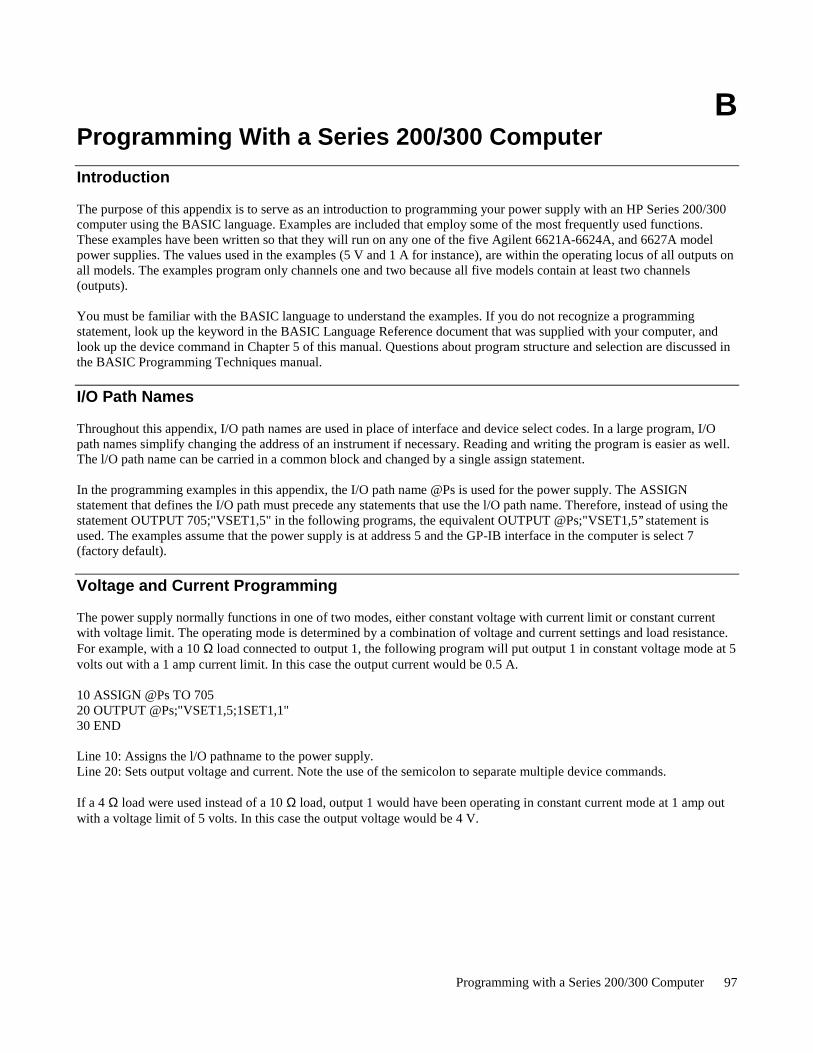
Programming with a Series 200/300 Computer 97
BProgramming With a Series 200/300 Computer
Introduction
The purpose of this appendix is to serve as an introduction to programming your power supply with an HP Series 200/300computer using the BASIC language. Examples are included that employ some of the most frequently used functions.These examples have been written so that they will run on any one of the five Agilent 6621A-6624A, and 6627A modelpower supplies. The values used in the examples (5 V and 1 A for instance), are within the operating locus of all outputs onall models. The examples program only channels one and two because all five models contain at least two channels(outputs).
You must be familiar with the BASIC language to understand the examples. If you do not recognize a programmingstatement, look up the keyword in the BASIC Language Reference document that was supplied with your computer, andlook up the device command in Chapter 5 of this manual. Questions about program structure and selection are discussed inthe BASIC Programming Techniques manual.
I/O Path Names
Throughout this appendix, I/O path names are used in place of interface and device select codes. In a large program, I/Opath names simplify changing the address of an instrument if necessary. Reading and writing the program is easier as well.The l/O path name can be carried in a common block and changed by a single assign statement.
In the programming examples in this appendix, the I/O path name @Ps is used for the power supply. The ASSIGNstatement that defines the I/O path must precede any statements that use the l/O path name. Therefore, instead of using thestatement OUTPUT 705;"VSET1,5" in the following programs, the equivalent OUTPUT @Ps;"VSET1,5’’ statement isused. The examples assume that the power supply is at address 5 and the GP-IB interface in the computer is select 7(factory default).
Voltage and Current Programming
The power supply normally functions in one of two modes, either constant voltage with current limit or constant currentwith voltage limit. The operating mode is determined by a combination of voltage and current settings and load resistance.For example, with a 10 Ω load connected to output 1, the following program will put output 1 in constant voltage mode at 5volts out with a 1 amp current limit. In this case the output current would be 0.5 A.
10 ASSIGN @Ps TO 70520 OUTPUT @Ps;"VSET1,5;1SET1,1"30 END
Line 10: Assigns the l/O pathname to the power supply.Line 20: Sets output voltage and current. Note the use of the semicolon to separate multiple device commands.
If a 4 Ω load were used instead of a 10 Ω load, output 1 would have been operating in constant current mode at 1 amp outwith a voltage limit of 5 volts. In this case the output voltage would be 4 V.

Programming with a Series 200/300 Computer98
Voltage and Current Programming With Variables
You can use variables in a program to represent data values in the device commands. This is useful in applications thatrequire changing the voltage and current values to different predetermined settings. The following program uses a variablein a FOR NEXT loop to ramp up output voltage in 0.1 volt steps from 0 to 5 volts.
10 ASSIGN @Ps TO 70520 OUTPUT @Ps;"CLR;ISET1,1"30 FOR Voltage=0 TO 5 STEP 0.140 OUTPUT @Ps;"VSET1,’’;Voltage50 WAIT 0.260 NEXT Voltage70 END
Line 10: Assigns the I/O pathname to the power supply.Line 20: Initializes the power supply to its power on state and sets the current limit.Line 30,60: Increments the voltage in 0.1 V steps to 5 volts.Line 40: Sets the voltage of output 1 to the value of the variable "Voltage’’. The comma inside the quotes is required
because it separates numbers in the device command (the output channel number from the voltage value in thiscase). A space < SP > may also be used instead of the comma. The semicolon outside the quotes is used because itsuppresses the <CR > <LF> that the computer would normally send to the power supply if a comma were used asa separator after a string item. Using a comma in this case would produce a syntax error in the power supply.
Line 50: Waits 0.2 seconds between steps.
Another way to use variables to represent data values in device commands is when using input statements to program thepower supply. The following program uses input statements to program the voltage and current settings of output 1 andoutput 2.
10 ASSIGN @Ps TO 70520 INPUT "ENTER A VOLTAGE FOR OUTPUT #1",V130 INPUT "ENTER A CURRENT LIMIT FOR OUTPUT #1",I140 INPUT ’’ENTER A VOLTAGE FOR OUTPUT #2",V250 INPUT "ENTER A CURRENT LIMIT FOR OUTPUT #2",I260 OUTPUT @Ps;’’VSET1,";V1;";ISET1,’’;I1;’’;VSET2,";V2;";ISET2,";I270 END
Line 10: Assigns the I/O pathname to the power supply.Line 20,30: Enter voltage and current values for output 1.Line 40,50: Enter voltage and current values for output 2.Line 60: Sets the voltage and current of outputs 1 and 2 to the values entered into the variables. The previous example
explained the use of the comma inside the quotes and the semicolon that precedes the variable. The semicolon thatfollows the variable suppresses the comma that the computer would normally send to the power supply if a commawere used as a separator after a numeric item. The leading semicolons inside the quotes separate multiple devicecommands (the VSET commands from the ISET commands in this case).
Voltage and Current Readback
Reading back data from the power supply requires two statements. First, an output statement is used to query the powersupply. A list of queries appears in Table 5-2. The power supply responds to the query by entering the requested data into abuffer. Next, an enter statement is used to read the data from the buffer on the power supply into a variable in the computer.The following program queries the power supply for the voltage and current settings of output 1 and prints the results onthe screen.
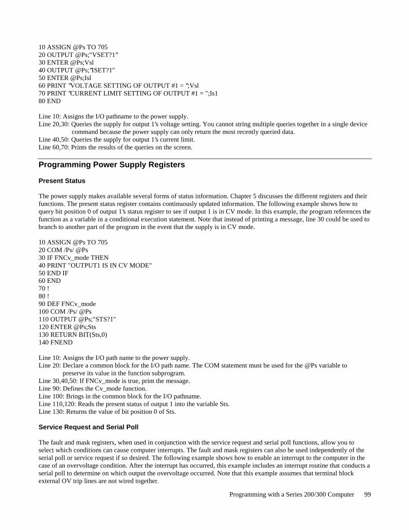
Programming with a Series 200/300 Computer 99
10 ASSIGN @Ps TO 70520 OUTPUT @Ps;"VSET?1’’30 ENTER @Ps;Vsl40 OUTPUT @Ps;’’ISET?1"50 ENTER @Ps;Isl60 PRINT ’’VOLTAGE SETTING OF OUTPUT #1 = ’’;Vsl70 PRINT ’’CURRENT LIMIT SETTING OF OUTPUT #1 = ";Is180 END
Line 10: Assigns the I/O pathname to the power supply.Line 20,30: Queries the supply for output 1’s voltage setting. You cannot string multiple queries together in a single device
command because the power supply can only return the most recently queried data.Line 40,50: Queries the supply for output 1’s current limit.Line 60,70: Prints the results of the queries on the screen.
Programming Power Supply Registers
Present Status
The power supply makes available several forms of status information. Chapter 5 discusses the different registers and theirfunctions. The present status register contains continuously updated information. The following example shows how toquery bit position 0 of output 1’s status register to see if output 1 is in CV mode. In this example, the program references thefunction as a variable in a conditional execution statement. Note that instead of printing a message, line 30 could be used tobranch to another part of the program in the event that the supply is in CV mode.
10 ASSIGN @Ps TO 70520 COM /Ps/ @Ps30 IF FNCv_mode THEN40 PRINT "OUTPUT1 IS IN CV MODE"50 END IF60 END70 !80 !90 DEF FNCv_mode100 COM /Ps/ @Ps110 OUTPUT @Ps;"STS?1"120 ENTER @Ps;Sts130 RETURN BIT(Sts,0)140 FNEND
Line 10: Assigns the I/O path name to the power supply.Line 20: Declare a common block for the I/O path name. The COM statement must be used for the @Ps variable to
preserve its value in the function subprogram.Line 30,40,50: If FNCv_mode is true, print the message.Line 90: Defines the Cv_mode function.Line 100: Brings in the common block for the I/O pathname.Line 110,120: Reads the present status of output 1 into the variable Sts.Line 130: Returns the value of bit position 0 of Sts.
Service Request and Serial Poll
The fault and mask registers, when used in conjunction with the service request and serial poll functions, allow you toselect which conditions can cause computer interrupts. The fault and mask registers can also be used independently of theserial poll or service request if so desired. The following example shows how to enable an interrupt to the computer in thecase of an overvoltage condition. After the interrupt has occurred, this example includes an interrupt routine that conducts aserial poll to determine on which output the overvoltage occurred. Note that this example assumes that terminal blockexternal OV trip lines are not wired together.
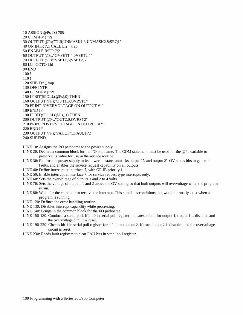
Programming with a Series 200/300 Computer100
10 ASSIGN @Ps TO 70520 COM /Ps/ @Ps30 OUTPUT @Ps;’’CLR;UNMASK1,8;UNMASK2,8;SRQ1’’40 ON INTR 7,1 CALL Err _ trap50 ENABLE INTR 7;260 OUTPUT @Ps;"OVSET1,4;0VSET2,4"70 OUTPUT @Ps;"VSET1,5;VSET2,5"80 Lbl: GOTO Lbl90 END100 !110 !120 SUB Err _ trap130 OFF INTR140 COM /Ps/ @Ps150 IF BlT(SPOLL(@Ps),0) THEN160 OUTPUT @Ps;’’OUT1,0;OVRST1’’170 PRINT ’’OVERVOLTAGE ON OUTPUT #1"180 END IF190 IF BIT(SPOLL(@Ps),1) THEN200 OUTPUT @Ps;"OUT2,0;OVRST2"210 PRINT "OVERVOLTAGE ON OUTPUT #2"220 END IF230 OUTPUT @Ps;’’FAULT?1;FAULT?2"240 SUBEND
LINE 10: Assigns the I/O pathname to the power supply.LINE 20: Declare a common block for the I/O pathname. The COM statement must be used for the @Ps variable to
preserve its value for use in the service routine.LINE 30: Returns the power supply to its power on state, unmasks output 1’s and output 2’s OV status bits to generate
faults, and enables the service request capability on all outputs.LINE 40: Define interrupt at interface 7, with GP-IB priority 1.LINE 50: Enable interrupt at interface 7 for service request type interrupts only.LINE 60: Sets the overvoltage of outputs 1 and 2 to 4 volts.LINE 70: Sets the voltage of outputs 1 and 2 above the OV setting so that both outputs will overvoltage when the program
is run.LINE 80: Waits for the computer to receive the interrupt. This simulates conditions that would normally exist when a
program is running.LINE 120: Defines the error handling routine.LINE 130: Disables interrupt capability while processing.LINE 140: Brings in the common block for the I/O pathname.LINE 150-180: Conducts a serial poll. If bit 0 in serial poll register indicates a fault for output 1, output 1 is disabled and
the overvoltage circuit is reset.LINE 190-220: Checks bit 1 in serial poll register for a fault on output 2. If true, output 2 is disabled and the overvoltage
circuit is reset.LINE 230: Reads fault registers to clear FAU bits in serial poll register.
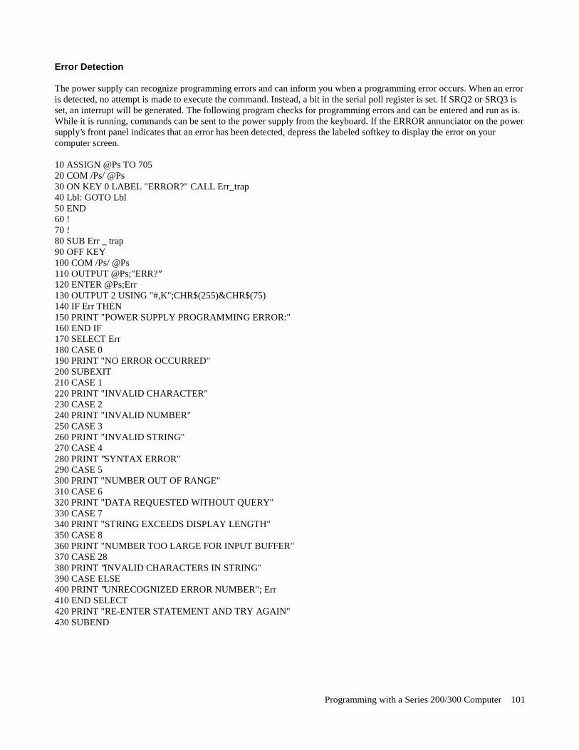
Programming with a Series 200/300 Computer 101
Error Detection
The power supply can recognize programming errors and can inform you when a programming error occurs. When an erroris detected, no attempt is made to execute the command. Instead, a bit in the serial poll register is set. If SRQ2 or SRQ3 isset, an interrupt will be generated. The following program checks for programming errors and can be entered and run as is.While it is running, commands can be sent to the power supply from the keyboard. If the ERROR annunciator on the powersupply’s front panel indicates that an error has been detected, depress the labeled softkey to display the error on yourcomputer screen.
10 ASSIGN @Ps TO 70520 COM /Ps/ @Ps30 ON KEY 0 LABEL "ERROR?" CALL Err_trap40 Lbl: GOTO Lbl50 END60 !70 !80 SUB Err _ trap90 OFF KEY100 COM /Ps/ @Ps110 OUTPUT @Ps;"ERR?’’120 ENTER @Ps;Err130 OUTPUT 2 USING "#,K";CHR$(255)&CHR$(75)140 IF Err THEN150 PRINT "POWER SUPPLY PROGRAMMING ERROR:"160 END IF170 SELECT Err180 CASE 0190 PRINT "NO ERROR OCCURRED"200 SUBEXIT210 CASE 1220 PRINT "INVALID CHARACTER"230 CASE 2240 PRINT "INVALID NUMBER"250 CASE 3260 PRINT "INVALID STRING"270 CASE 4280 PRINT ’’SYNTAX ERROR"290 CASE 5300 PRINT "NUMBER OUT OF RANGE"310 CASE 6320 PRINT "DATA REQUESTED WlTHOUT QUERY"330 CASE 7340 PRINT "STRING EXCEEDS DISPLAY LENGTH"350 CASE 8360 PRINT "NUMBER TOO LARGE FOR INPUT BUFFER"370 CASE 28380 PRINT ’’INVALID CHARACTERS IN STRING"390 CASE ELSE400 PRINT ’’UNRECOGNIZED ERROR NUMBER"; Err410 END SELECT420 PRINT "RE-ENTER STATEMENT AND TRY AGAIN"430 SUBEND
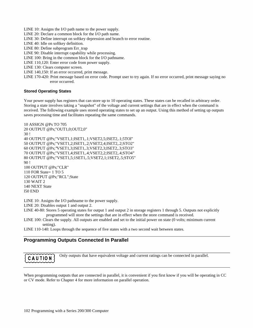
Programming with a Series 200/300 Computer102
LINE 10: Assigns the I/O path name to the power supply.LINE 20: Declare a common block for the I/O path name.LINE 30: Define interrupt on softkey depression and branch to error routine.LINE 40: Idle on softkey definition.LINE 80: Define subprogram Err_trapLINE 90: Disable interrupt capability while processing.LINE 100: Bring in the common block for the I/O pathname.LINE 110,120: Enter error code from power supply.LINE 130: Clears computer screen.LINE 140,150: If an error occurred, print message.LINE 170-420: Print message based on error code. Prompt user to try again. If no error occurred, print message saying no
error occurred.
Stored Operating States
Your power supply has registers that can store up to 10 operating states. These states can be recalled in arbitrary order.Storing a state involves taking a "snapshot" of the voltage and current settings that are in effect when the command isreceived. The following example uses stored operating states to set up an output. Using this method of setting up outputssaves processing time and facilitates repeating the same commands.
10 ASSIGN @Ps TO 70520 OUTPUT @Ps;"OUT1,0;OUT2,0"30 !40 OUTPUT @Ps;"VSET1,1;ISET1,.1;VSET2,5;ISET2,.1;5TOl"50 OUTPUT @Ps;"VSET1,2;ISET1,.2;VSET2,4;ISET2,.2;STO2"60 OUTPUT @Ps;’’VSET1,3;ISET1,.3;VSET2,3;ISET2,.3;STO3"70 OUTPUT @Ps;"VSET1,4;ISET1,.4;VSET2,2;ISET2,.4;STO4’’80 OUTPUT @Ps;"VSET1,5;1SET1,.5;VSET2,1;1SET2,.5;STO5"90 !100 OUTPUT @Ps;"CLR"110 FOR State= 1 TO 5120 OUTPUT @Ps;"RCL";State130 WAIT 2140 NEXT Statel50 END
LINE 10: Assigns the I/O pathname to the power supply.LINE 20: Disables output 1 and output 2.LINE 40-80: Stores 5 operating states for output 1 and output 2 in storage registers 1 through 5. Outputs not explicitly
programmed will store the settings that are in effect when the store command is received.LINE 100: Clears the supply. All outputs are enabled and set to the initial power on state (0 volts; minimum current
setting).LINE 110-140: Loops through the sequence of five states with a two second wait between states.
Programming Outputs Connected In Parallel
Only outputs that have equivalent voltage and current ratings can be connected in parallel.
When programming outputs that are connected in parallel, it is convenient if you first know if you will be operating in CCor CV mode. Refer to Chapter 4 for more information on parallel operation.
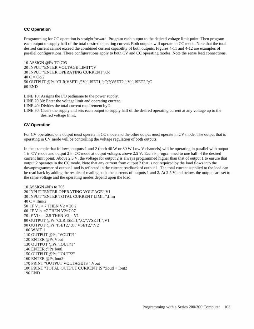
Programming with a Series 200/300 Computer 103
CC Operation
Programming for CC operation is straightforward. Program each output to the desired voltage limit point. Then programeach output to supply half of the total desired operating current. Both outputs will operate in CC mode. Note that the totaldesired current cannot exceed the combined current capability of both outputs. Figures 4-11 and 4-12 are examples ofparallel configurations. These configurations apply to both CV and CC operating modes. Note the sense lead connections.
10 ASSIGN @Ps TO 70520 INPUT "ENTER VOLTAGE LIMIT’’,V30 INPUT "ENTER OPERATING CURRENT",Oc40 C = Oc/250 OUTPUT @Ps;"CLR;VSET1,’’;V;";ISET1,";C;";VSET2,";V;";ISET2,";C60 END
LINE 10: Assigns the I/O pathname to the power supply.LINE 20,30: Enter the voltage limit and operating current.LINE 40: Divides the total current requirement by 2.LINE 50: Clears the supply and sets each output to supply half of the desired operating current at any voltage up to the
desired voltage limit.
CV Operation
For CV operation, one output must operate in CC mode and the other output must operate in CV mode. The output that isoperating in CV mode will be controlling the voltage regulation of both outputs.
In the example that follows, outputs 1 and 2 (both 40 W or 80 W Low V channels) will be operating in parallel with output1 in CV mode and output 2 in CC mode at output voltages above 2.5 V. Each is programmed to one half of the desiredcurrent limit point. Above 2.5 V, the voltage for output 2 is always programmed higher than that of output 1 to ensure thatoutput 2 operates in the CC mode. Note that any current from output 2 that is not required by the load flows into thedownprogrammer of output 1 and is reflected in the current readback of output 1. The total current supplied to the load canbe read back by adding the results of reading back the currents of outputs 1 and 2. At 2.5 V and below, the outputs are set tothe same voltage and the operating modes depend upon the load.
10 ASSIGN @Ps to 70520 INPUT "ENTER OPERATING VOLTAGE",V130 INPUT "ENTER TOTAL CURRENT LIMIT",Ilim40 C = Ilim/250 IF V1 > 7 THEN V2 = 20.260 IF V1< =7 THEN V2=7.0770 IF Vl < = 2.5 THEN V2 = V180 OUTPUT @Ps;"CLR;ISET1,";C;";VSET1,";V190 OUTPUT @Ps;’’ISET2,";C;"VSET2,";V2100 WAIT 1110 OUTPUT @Ps;"VOUT?1"120 ENTER @Ps;Vout130 OUTPUT @Ps;"IOUT?1’’140 ENTER @Ps;Ioutl150 OUTPUT @Ps;"IOUT?2"160 ENTER @Ps;Iout2170 PRINT "OUTPUT VOLTAGE IS ";Vout180 PRINT "TOTAL OUTPUT CURRENT IS ";Ioutl + Iout2190 END
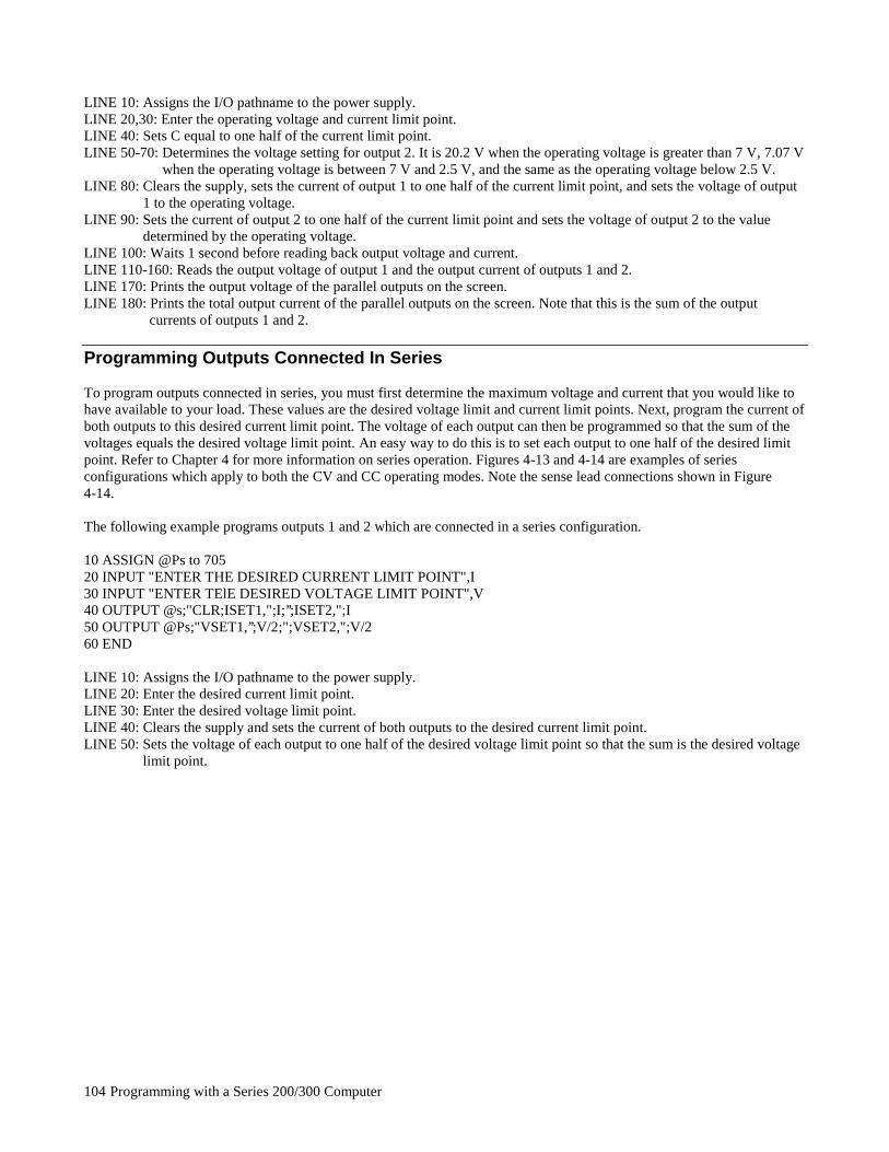
Programming with a Series 200/300 Computer104
LINE 10: Assigns the I/O pathname to the power supply.LINE 20,30: Enter the operating voltage and current limit point.LINE 40: Sets C equal to one half of the current limit point.LINE 50-70: Determines the voltage setting for output 2. It is 20.2 V when the operating voltage is greater than 7 V, 7.07 V
when the operating voltage is between 7 V and 2.5 V, and the same as the operating voltage below 2.5 V.LINE 80: Clears the supply, sets the current of output 1 to one half of the current limit point, and sets the voltage of output
1 to the operating voltage.LINE 90: Sets the current of output 2 to one half of the current limit point and sets the voltage of output 2 to the value
determined by the operating voltage.LINE 100: Waits 1 second before reading back output voltage and current.LINE 110-160: Reads the output voltage of output 1 and the output current of outputs 1 and 2.LINE 170: Prints the output voltage of the parallel outputs on the screen.LINE 180: Prints the total output current of the parallel outputs on the screen. Note that this is the sum of the output
currents of outputs 1 and 2.
Programming Outputs Connected In Series
To program outputs connected in series, you must first determine the maximum voltage and current that you would like tohave available to your load. These values are the desired voltage limit and current limit points. Next, program the current ofboth outputs to this desired current limit point. The voltage of each output can then be programmed so that the sum of thevoltages equals the desired voltage limit point. An easy way to do this is to set each output to one half of the desired limitpoint. Refer to Chapter 4 for more information on series operation. Figures 4-13 and 4-14 are examples of seriesconfigurations which apply to both the CV and CC operating modes. Note the sense lead connections shown in Figure4-14.
The following example programs outputs 1 and 2 which are connected in a series configuration.
10 ASSIGN @Ps to 70520 INPUT "ENTER THE DESIRED CURRENT LIMIT POINT",I30 INPUT "ENTER TElE DESIRED VOLTAGE LIMIT POINT",V40 OUTPUT @s;"CLR;ISET1,";I;’’;ISET2,";I50 OUTPUT @Ps;"VSET1,’’;V/2;";VSET2,";V/260 END
LINE 10: Assigns the I/O pathname to the power supply.LINE 20: Enter the desired current limit point.LINE 30: Enter the desired voltage limit point.LINE 40: Clears the supply and sets the current of both outputs to the desired current limit point.LINE 50: Sets the voltage of each output to one half of the desired voltage limit point so that the sum is the desired voltage
limit point.
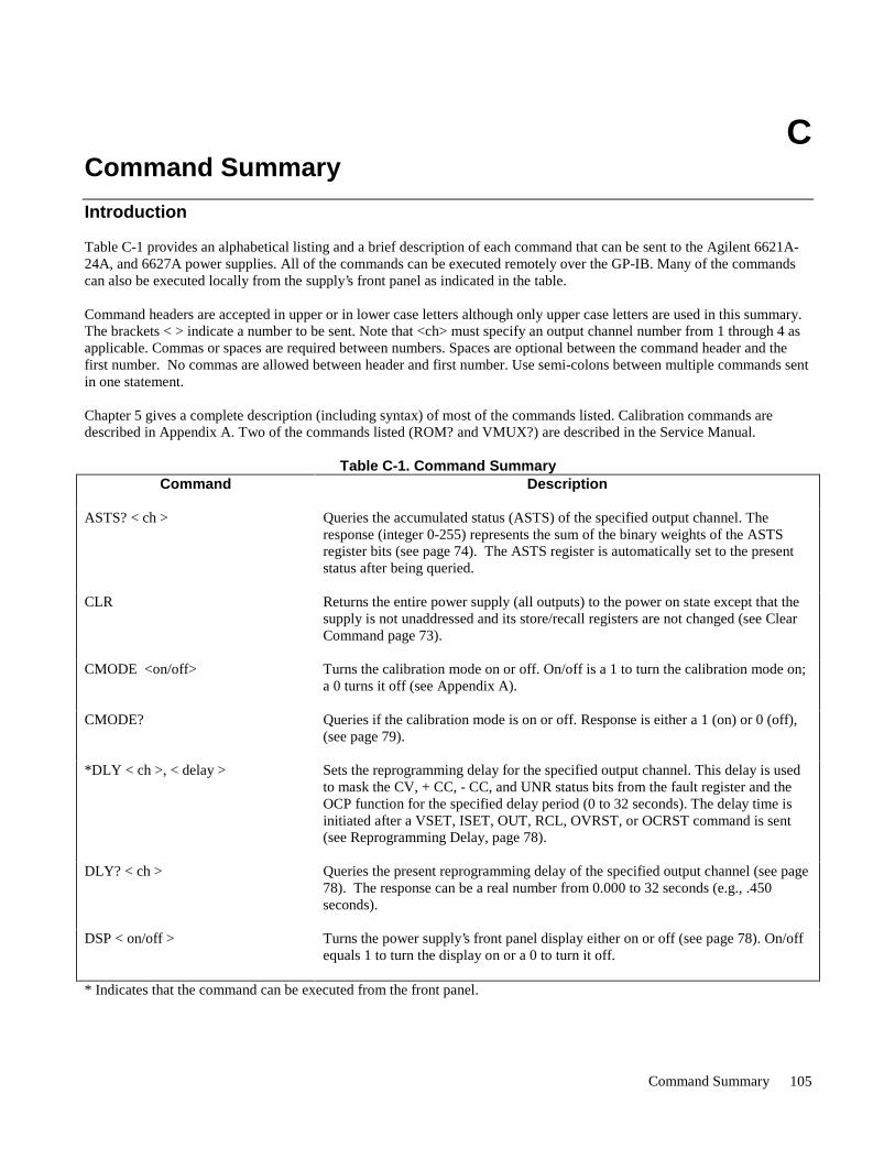
Command Summary 105
CCommand Summary
Introduction
Table C-1 provides an alphabetical listing and a brief description of each command that can be sent to the Agilent 6621A-24A, and 6627A power supplies. All of the commands can be executed remotely over the GP-IB. Many of the commandscan also be executed locally from the supply’s front panel as indicated in the table.
Command headers are accepted in upper or in lower case letters although only upper case letters are used in this summary.The brackets < > indicate a number to be sent. Note that <ch> must specify an output channel number from 1 through 4 asapplicable. Commas or spaces are required between numbers. Spaces are optional between the command header and thefirst number. No commas are allowed between header and first number. Use semi-colons between multiple commands sentin one statement.
Chapter 5 gives a complete description (including syntax) of most of the commands listed. Calibration commands aredescribed in Appendix A. Two of the commands listed (ROM? and VMUX?) are described in the Service Manual.
Table C-1. Command SummaryCommand Description
ASTS? < ch > Queries the accumulated status (ASTS) of the specified output channel. Theresponse (integer 0-255) represents the sum of the binary weights of the ASTSregister bits (see page 74). The ASTS register is automatically set to the presentstatus after being queried.
CLR Returns the entire power supply (all outputs) to the power on state except that thesupply is not unaddressed and its store/recall registers are not changed (see ClearCommand page 73).
CMODE <on/off> Turns the calibration mode on or off. On/off is a 1 to turn the calibration mode on;a 0 turns it off (see Appendix A).
CMODE? Queries if the calibration mode is on or off. Response is either a 1 (on) or 0 (off),(see page 79).
*DLY < ch >, < delay > Sets the reprogramming delay for the specified output channel. This delay is usedto mask the CV, + CC, - CC, and UNR status bits from the fault register and theOCP function for the specified delay period (0 to 32 seconds). The delay time isinitiated after a VSET, ISET, OUT, RCL, OVRST, or OCRST command is sent(see Reprogramming Delay, page 78).
DLY? < ch > Queries the present reprogramming delay of the specified output channel (see page78). The response can be a real number from 0.000 to 32 seconds (e.g., .450seconds).
DSP < on/off > Turns the power supply’s front panel display either on or off (see page 78). On/offequals 1 to turn the display on or a 0 to turn it off.
* Indicates that the command can be executed from the front panel.
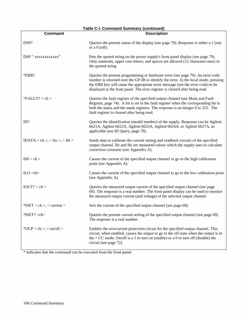
Command Summary106
Table C-l. Command Summary (continued)Command Description
DSP? Queries the present status of the display (see page 78). Response is either a 1 (on)or a 0 (off).
DSP " xxxxxxxxxxxx” Puts the quoted string on the power supply's front panel display (see page 79).Only numerals, upper case letters, and spaces are allowed (12 characters max) inthe quoted string
*ERR? Queries the present programming or hardware error (see page 79). An error codenumber is returned over the GP-IB to identify the error. In the local mode, pressingthe ERR key will cause the appropriate error message (not the error code) to bedisplayed at the front panel. The error register is cleared after being read.
*FAULT? < ch > Queries the fault register of the specified output channel (see Mask and FaultRegister, page 74). A bit is set in the fault register when the corresponding bit inboth the status and the mask registers. The response is an integer 0 to 255. Thefault register is cleared after being read.
ID? Queries the identification (model number) of the supply. Response can be Agilent6621A, Agilent 6622A, Agilent 6623A, Agilent 6624A, or Agilent 6627A, asapplicable (see ID Query, page 79).
IDATA < ch >, < Ilo >, < Ihi > Sends data to calibrate the current setting and readback circuits of the specifiedoutput channel. Ilo and Ihi are measured values which the supply uses to calculatecorrection constants (see Appendix A).
IHI < ch > Causes the current of the specified output channel to go to the high calibrationpoint (see Appendix A).
ILO <ch> Causes the current of the specified output channel to go to the low calibration point(see Appendix A).
IOUT? < ch > Queries the measured output current of the specified output channel (see page69). The response is a real number. The front panel display can be used to monitorthe measured output current (and voltage) of the selected output channel.
*ISET < ch >, < current > Sets the current of the specified output channel (see page 69).
*ISET? <ch> Queries the present current setting of the specified output channel (see page 69).The response is a real number.
*OCP < ch >, < on/off > Enables the overcurrent protection circuit for the specified output channel. Thiscircuit, when enabled, causes the output to go to the off state when the output is inthe + CC mode. On/off is a 1 to turn on (enable) or a 0 to turn off (disable) thecircuit (see page 72).
* Indicates that the command can be executed from the front panel.
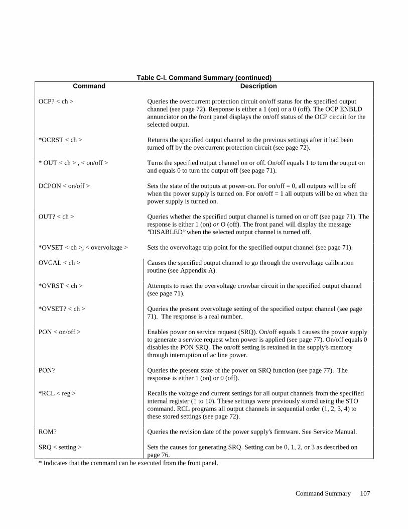
Command Summary 107
Table C-l. Command Summary (continued)Command Description
OCP? < ch > Queries the overcurrent protection circuit on/off status for the specified outputchannel (see page 72). Response is either a 1 (on) or a 0 (off). The OCP ENBLDannunciator on the front panel displays the on/off status of the OCP circuit for theselected output.
*OCRST < ch > Returns the specified output channel to the previous settings after it had beenturned off by the overcurrent protection circuit (see page 72).
* OUT < ch > , < on/off > Turns the specified output channel on or off. On/off equals 1 to turn the output onand equals 0 to turn the output off (see page 71).
DCPON < on/off > Sets the state of the outputs at power-on. For on/off = 0, all outputs will be offwhen the power supply is turned on. For on/off = 1 all outputs will be on when thepower supply is turned on.
OUT? < ch > Queries whether the specified output channel is turned on or off (see page 71). Theresponse is either 1 (on) or O (off). The front panel will display the message’’DISABLED’’ when the selected output channel is turned off.
*OVSET < ch >, < overvoltage > Sets the overvoltage trip point for the specified output channel (see page 71).
OVCAL < ch > Causes the specified output channel to go through the overvoltage calibrationroutine (see Appendix A).
*OVRST < ch > Attempts to reset the overvoltage crowbar circuit in the specified output channel(see page 71).
*OVSET? < ch > Queries the present overvoltage setting of the specified output channel (see page71). The response is a real number.
PON < on/off > Enables power on service request (SRQ). On/off equals 1 causes the power supplyto generate a service request when power is applied (see page 77). On/off equals 0disables the PON SRQ. The on/off setting is retained in the supply’s memorythrough interruption of ac line power.
PON? Queries the present state of the power on SRQ function (see page 77). Theresponse is either 1 (on) or 0 (off).
*RCL < reg > Recalls the voltage and current settings for all output channels from the specifiedinternal register (1 to 10). These settings were previously stored using the STOcommand. RCL programs all output channels in sequential order (1, 2, 3, 4) tothese stored settings (see page 72).
ROM? Queries the revision date of the power supply’s firmware. See Service Manual.
SRQ < setting > Sets the causes for generating SRQ. Setting can be 0, 1, 2, or 3 as described onpage 76.
* Indicates that the command can be executed from the front panel.
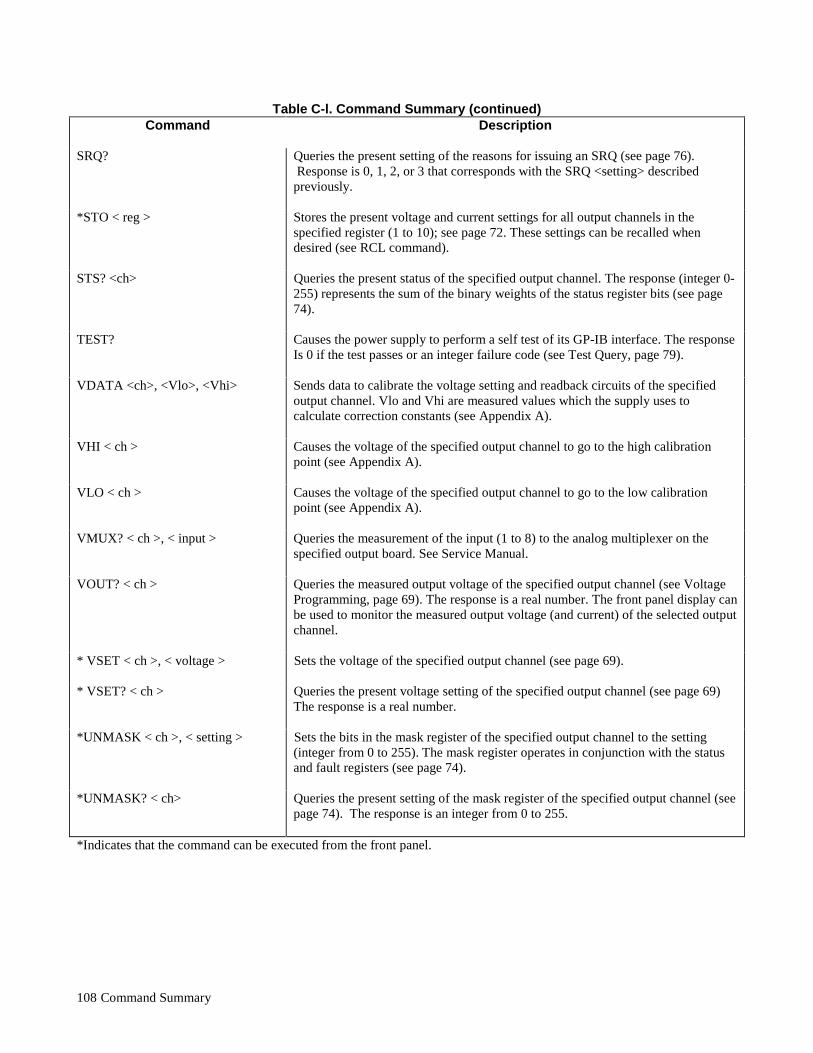
Command Summary108
Table C-l. Command Summary (continued)Command Description
SRQ? Queries the present setting of the reasons for issuing an SRQ (see page 76). Response is 0, 1, 2, or 3 that corresponds with the SRQ <setting> describedpreviously.
*STO < reg > Stores the present voltage and current settings for all output channels in thespecified register (1 to 10); see page 72. These settings can be recalled whendesired (see RCL command).
STS? <ch> Queries the present status of the specified output channel. The response (integer 0-255) represents the sum of the binary weights of the status register bits (see page74).
TEST? Causes the power supply to perform a self test of its GP-IB interface. The responseIs 0 if the test passes or an integer failure code (see Test Query, page 79).
VDATA <ch>, <Vlo>, <Vhi> Sends data to calibrate the voltage setting and readback circuits of the specifiedoutput channel. Vlo and Vhi are measured values which the supply uses tocalculate correction constants (see Appendix A).
VHI < ch > Causes the voltage of the specified output channel to go to the high calibrationpoint (see Appendix A).
VLO < ch > Causes the voltage of the specified output channel to go to the low calibrationpoint (see Appendix A).
VMUX? < ch >, < input > Queries the measurement of the input (1 to 8) to the analog multiplexer on thespecified output board. See Service Manual.
VOUT? < ch > Queries the measured output voltage of the specified output channel (see VoltageProgramming, page 69). The response is a real number. The front panel display canbe used to monitor the measured output voltage (and current) of the selected outputchannel.
* VSET < ch >, < voltage > Sets the voltage of the specified output channel (see page 69).
* VSET? < ch > Queries the present voltage setting of the specified output channel (see page 69)The response is a real number.
*UNMASK < ch >, < setting > Sets the bits in the mask register of the specified output channel to the setting(integer from 0 to 255). The mask register operates in conjunction with the statusand fault registers (see page 74).
*UNMASK? < ch> Queries the present setting of the mask register of the specified output channel (seepage 74). The response is an integer from 0 to 255.
*Indicates that the command can be executed from the front panel.
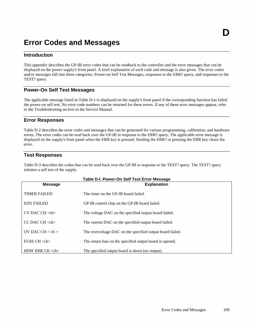
Error Codes and Messages 109
DError Codes and Messages
Introduction
This appendix describes the GP-IB error codes that can be readback to the controller and the error messages that can bedisplayed on the power supply’s front panel. A brief explanation of each code and message is also given. The error codesand/or messages fall into three categories: Power-on Self Test Messages, responses to the ERR? query, and responses to theTEST? query.
Power-On Self Test Messages
The applicable message listed in Table D-1 is displayed on the supply’s front panel if the corresponding function has failedthe power-on self test. No error code numbers can be returned for these errors. If any of these error messages appear, referto the Troubleshooting section in the Service Manual.
Error Responses
Table D-2 describes the error codes and messages that can be generated for various programming, calibration, and hardwareerrors. The error codes can be read back over the GP-IB in response to the ERR? query. The applicable error message isdisplayed on the supply’s front panel when the ERR key is pressed. Sending the ERR? or pressing the ERR key clears theerror.
Test Responses
Table D-3 describes the codes that can be read back over the GP-IB in response to the TEST? query. The TEST? queryinitiates a self test of the supply.
Table D-l. Power-On Self Test Error MessageMessage Explanation
TIMER FAILED The timer on the GP-IB board failed.
8291 FAILED GP-IB control chip on the GP-IB board failed.
CV DAC CH <ch> The voltage DAC on the specified output board failed.
CC DAC CH <ch> The current DAC on the specified output board failed.
OV DAC CH < ch > The overvoltage DAC on the specified output board failed.
FUSE CH <ch> The return fuse on the specified output board is opened.
HDW ERR CH <ch> The specified output board is down (no output).

Error Codes and Messages110
Table D-2. ERROR ResponsesError Code
(ERR? query)Message(ERR key)
Explanation
0 NO ERROR Indicates there are no errors.
1 INVALID CHAR You sent the supply a character it did not recognize.
2 INVALID NUM The format of your number is incorrect. Check syntax (see Chapter 5).
3 or 28 INVALID STR You sent a command the supply does not understand. Resend a recognizablecommand.
4 SYNTAX ERROR You sent a command with improper syntax. Check syntax of your command (seeChapter 5).
5 NUMBER RANGE An out of range number was sent. Send a new number within the legal range.
6 NO QUERY The computer addressed the supply to talk, but it did not first request data. Sendquery first and then address the supply to talk.
7 DISP LENGTH Quoted string in the DSP command exceeds the display length of 12 characters.
8 BUFFER FULL May occur if too many numbers are sent. Error code 4 or error code 5 are morelikely to occur for this condition.
9 EEPROM ERROR The EEPROM on the GP-IB board is not responding correctly to programmingcommands. An instrument failure has occurred and service is required. Refer tothe Troubleshooting Section in the Service Manual.
10 HARDWARE ERR An output error has occurred on an unknown output. Service is required. Referto the Troubleshooting Section in the Service Manual.
11 HDW ERR CH 1 Error codes 11 through 14 refer to a specific output where an output error hasoccurred. Service is required. Refer to the Output Board Troubleshooting sectionin the Service Manual.
12 HDW ERR CH 2 Same as in error 11.
13 HDW ERR CH 3 Same as in error 11.
14 HDW ERR CH 4 Same as in error 11.
15 NO MODEL NUM The supply’s model number cannot be found. The GP-IB Interface board may bedefective or the supply may require reprogramming. Refer to theTroubleshooting section of the Service Manual.
16 CAL ERROR An error has occurred during calibration. This may be the result of out of rangenumbers sent. If recalibration (See Appendix A) does not fix this there may be ahardware failure (Refer to the Troubleshooting Section in the Service Manual).
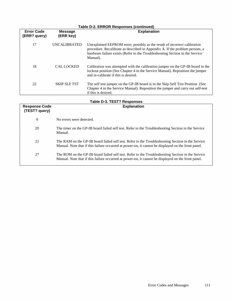
Error Codes and Messages 111
Table D-2. ERROR Responses (continued)Error Code
(ERR? query)Message(ERR key)
Explanation
17 UNCALIBRATED Unexplained EEPROM error; possibly as the result of incorrect calibrationprocedure. Recalibrate as described in Appendix A. If the problem persists, ahardware failure exists (Refer to the Troubleshooting Section in the ServiceManual).
18 CAL LOCKED Calibration was attempted with the calibration jumper on the GP-IB board in thelockout position (See Chapter 4 in the Service Manual). Reposition the jumperand re-calibrate if this is desired.
22 SKIP SLF TST The self test jumper on the GP-IB board is in the Skip Self Test Position (SeeChapter 4 in the Service Manual). Reposition the jumper and carry out self-testif this is desired.
Table D-3. TEST? ResponsesResponse Code(TEST? query)
Explanation
0 No errors were detected.
20 The timer on the GP-IB board failed self test. Refer to the Troubleshooting Section in the ServiceManual.
21 The RAM on the GP-IB board failed self test. Refer to the Troubleshooting Section in the ServiceManual. Note that if this failure occurred at power-on, it cannot be displayed on the front panel.
27 The ROM on the GP-IB board failed self test. Refer to the Troubleshooting Section in the ServiceManual. Note that if this failure occurred at power-on, it cannot be displayed on the front panel.

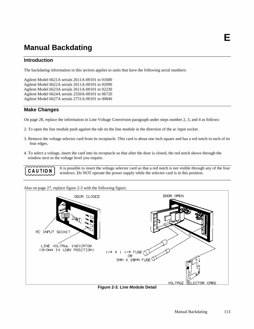
Manual Backdating 113
EManual Backdating
Introduction
The backdating information in this section applies to units that have the following serial numbers:
Agilent Model 6621A serials 2611A-00101 to 01680Agilent Model 6622A serials 2611A-00101 to 02090Agilent Model 6623A serials 2611A-00101 to 02230Agilent Model 6624A serials 2550A-00101 to 06720Agilent Model 6627A serials 2751A-00101 to 00840
Make Changes
On page 28, replace the information in Line Voltage Conversion paragraph under steps number 2, 3, and 4 as follows:
2. To open the line module push against the tab on the line module in the direction of the ac input socket.
3. Remove the voltage selector card from its receptacle. This card is about one inch square and has a red notch in each of itsfour edges.
4. To select a voltage, insert the card into its receptacle so that after the door is closed, the red notch shows through thewindow next to the voltage level you require.
It is possible to insert the voltage selector card so that a red notch is not visible through any of the fourwindows. Do NOT operate the power supply while the selector card is in this position.
Also on page 27, replace figure 2-3 with the following figure;
Figure 2-3. Line Module Detail

Agilent Sales and Support Office 114
Agilent Sales and Support Office
For more information about Agilent Technologies test and measurement products, applications, services, and for a current sales office listing, visit our web site: http://www.agilent.com/find/tmdir
You can also contact one of the following centers and ask for a test and measurement sales representative.
United States: Agilent Technologies Test and Measurement Call Center P.O. Box 4026 Englewood, CO 80155-4026 (tel) 1 800 452 4844
Latin America: Agilent Technologies Latin American Region Headquarters 5200 Blue Lagoon Drive, Suite #950 Miami, Florida 33126 U.S.A. (tel) (305) 267 4245 (fax) (305) 267 4286
Canada: Agilent Technologies Canada Inc. 5150 Spectrum Way Mississauga, Ontario L4W 5G1 (tel) 1 877 894 4414
Australia/New Zealand: Agilent Technologies Australia Pty Ltd 347 Burwood Highway Forest Hill, Victoria 3131 (tel) 1-800 629 485 (Australia) (fax) (61 3) 9272 0749 (tel) 0 800 738 378 (New Zealand) (fax) (64 4) 802 6881
Europe: Agilent Technologies Test & Measurement European Marketing Organisation P.O. Box 999 1180 AZ Amstelveen The Netherlands (tel) (31 20) 547 9999
Asia Pacific: Agilent Technologies 24/F, Cityplaza One, 1111 King's Road, Taikoo Shing, Hong Kong tel: (852)-3197-7777 fax: (852)-2506-9284
Japan: Agilent Technologies Japan Ltd. Measurement Assistance Center 9-1, Takakura-Cho, Hachioji-Shi, Tokyo 192-8510, Japan (tel) (81) 426 56 7832 (fax) (81) 426 56 7840
Technical data is subject to change.
Manual Updates The following updates have been made to this manual since the print revision indicated on the title page. 2/01/00 All references to HP have been changed to Agilent. All references to HP-IB have been changed to GPIB. 9/20/04 The Declaration of Conformity has been updated. 5/11/09 A URL has been added to the declaration page to obtain the latest declaration of conformity. The RF field annotation note has been removed from Table 1-2. The addendum at the back of the manual has been removed.


![Volvo Cars - docshare04.docshare.tipsdocshare04.docshare.tips/files/25008/250082579.pdfOperating income SEK1,636 million (2011) [1] Employees 21,512 (2011)[1] Parent Zhejiang Geely](https://img.dokumen.tips/doc/110x75/60d4af4aae8bec69db31a44a/volvo-cars-operating-income-sek1636-million-2011-1-employees-21512-20111.jpg)