Embed Size (px)
Citation preview
Metrology is Our Science, Accuracy is Our Business™
www.mintl.com • [email protected]
Data Subject to Change – 2021-09-24 1 of 5
Featuring Based on Proven NMI Design
Range: 100 kΩ to 10 PΩ
Voltages: 1 V to 1000 V (5000 V Optional)
Automatic and Manual Operation
Not Affected by Temperature Change
10 and 20-Channel Coaxial Matrix Scanners (Optional)
Environmental & Pressure Monitoring (Optional)
Ratio 1:1, 10:1, 100:1, 1000:1
Multiple Modes of Operation
OverviewMeasurements International, (MI), in keeping with “Metrology is our Science, Accuracy is our Business™”, has introduced the first commercially available Automated Dual Source High Resistance Bridge (model 6600A). The Dual Source High Resistance Bridge principle has become the primary measurement
technique of all National Measurement Laboratories (NMIs) around the world due to its unprecedented level of accuracy and stability over various other methods. Multiple modes of operation in the 6600A allows users to make resistance measurements in different ways.
Feature BenefitOnly true ratio bridge mode for direct comparison of high resistance standards..
Customers get the very best in commerically available technology.
Offers only high resistance bridge with any voltage-between 0 and 1000 V.
Customers are no longer limited in selected voltage through resistors.
Offers any ratio up to 1000:1. Users can fully use any ratio up to 1000:1 and are not limited in ratio.
Voltages can be extended to 5000 V. Allows users to extend voltage range beyond 1000 V up to 5000 V.
Based on NMI chosen technology. Gives users the ability to use leading edge highest precision measurement technology.
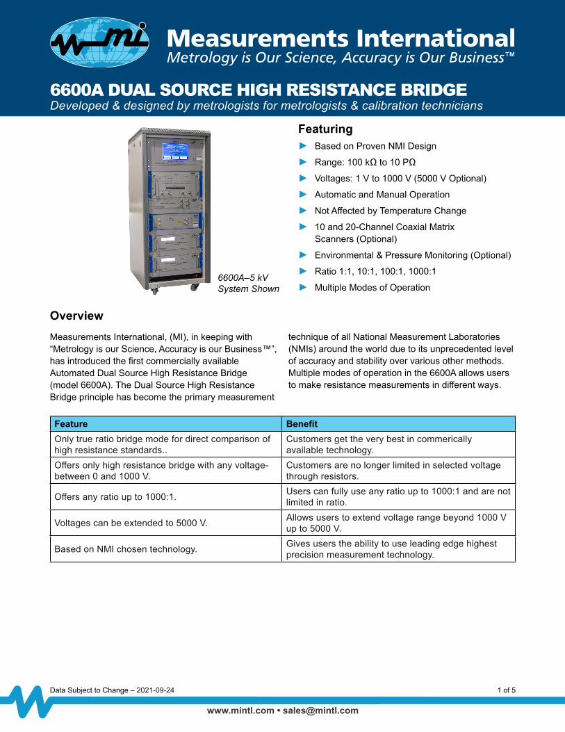
6600A DUAL SOURCE HIGH RESISTANCE BRIDGEDeveloped & designed by metrologists for metrologists & calibration technicians
6600A–5 kV System Shown

Metrology is Our Science, Accuracy is Our Business™
www.mintl.com • [email protected]
6600A DUAL SOURCE HIGH RESISTANCE BRIDGE
Data Subject to Change – 2021-09-24 2 of 5
Bridge ModeUsing the Bridge mode, the UUT is measured live against a standard reference resistor where the ratio of the sources is equal to the ratio of resistances (E1/E2 = R1/R2). This is the most accurate and reliable type of measurement for high resistance. Lead set N-type to N-type cables are supplied.
Direct Mode and Insulation Resistance ModeThe Direct and Insulation Resistance modes which are made on the R1 (shown in Figure 1) channel allow users to perform teraohmmeter type measurements without the need of connecting a reference standard resistor where R = E1/I1. These modes are useful to determine the nominal value of the resistor, its settle time, leakage resistance, etc. N-type to N-type lead and N-type to alligator lead are supplied.
All modes of operation offer users the flexibility to choose UUT test voltages from 1 V to 1000 V with six digits of resolution. Other commercially available units are limited within this range and do not allow the full freedom that the MI 6600A can offer.
Metrologists in any laboratory now have the ability to achieve measurable results and uncertainties that were previously only achievable in the highest of NMI laboratories for measurements above 100 MΩ. This is due to the advanced technology of the Dual Source Bridge. While other commercially available “meters” are limited to only measure one artifact at a time, the 6600A offers an actual “true bridge” measurement mode to complete this process where a known standard is measured against an unknown resistor in “true bridge” technology form. Ratios of 1:1, 10:1, 100:1 or even 1000:1 can be made with the best uncertainties being measured at ratio 1:1 or 10:1 at any voltage.
Ratio Measurement Principle (Figure 1)The Bridge architecture in the 6600A is formed by substituting two of the resistive arms of a Wheatstone bridge circuit
with low-impedance digitally-programmable voltage sources.
Voltage SourcesThe 1000 V DC sources in the 6600A offer voltage ratios of 1:1, 10:1, 100:1 and 1000:1 or any ratio in between. The voltage settings can be observed on the front panel display. The model 6600A is the only commercially available high resistance bridge which offers any selectable voltage between 1 V to 1000 V. Other manufacturers are limited to specific voltages within the set range of 1 V to 1000 V. The 6600A is housed in a shielded chamber to limit the effect of the outside environment due to air movement and static electricity caused by people passing by or technicians working in the area.
6600A CalibrationCalibration of the 6600A is achieved by calibrating the sources and the electrometer. A Diagnostic menu included in the software allows the user to run diagnostics on all the units in the system. A built-in calibration routine which controls an external calibrated 3458A DMM calibrates the sources one at a time. Source voltages are measured and stored automatically in the source table as Source 1 and Source 2 as offsets from nominal. Figure 2 shows an example of Source 1 calibration. These offsets (Delta) are applied to the voltages selected during measurement. As an alternative with better accuracy, Figure 1. Bridge Block Diagram
Figure 2. Source Calibration Example

Metrology is Our Science, Accuracy is Our Business™
www.mintl.com • [email protected]
6600A DUAL SOURCE HIGH RESISTANCE BRIDGE
Data Subject to Change – 2021-09-24 3 of 5
the MI model 8000B system can be used to calibrate the sources.
Electrometer calibration is achieved by using a calibrated source and calibrated resistor to determine the absolute current readings on the electrometer (Figure 3 shows the electrometer calibration example). The effect of the uncertainty on the electrometer is reduced greatly when the 6600A is operated in the bridge mode as the electrometer is used over a very small window reducing the type-B uncertainty to effectively zero leaving only the type-A uncertainty. In the direct mode, the type-B uncertainty combined with the type-A uncertainty is used.
Leakage PathsIn the 6600A, the resistors are measured with the case grounded, so that a leakage resistance path between the high terminal of the resistor and case is effectively in parallel with the voltage source A, and does not contribute to any measurement errors. Terminal leakage resistance at the low resistor terminal is effectively in parallel with the detector where a very small voltage is present to drive this leakage.
Connections and Thermal VoltagesThe resistors are connected to R1 and R2. Either can be designated as the standard. The reversal method is used to eliminate thermal voltage signals and to allow the capacitance effect of the leads and the resistor time constant to settle.
SoftwareMaking a measurement on the 6600A is simple, the software allows the user to define the measurement and test parameters utilizing the same proven software used on the MI 6010 and 6000 series of DC Bridges that our customers have become accustomed to. Features include resistor protection, settle time to verify time constants of resistors, number of measurements, statistics, voltage, temperature coefficients and graphing.
The Programs menu allows users to create and combine several program tasks such as intercomparing standards to standards, standards to measurands, and measurands to measurands. Selectable parameters include measurement time delays (wait times), reversal rate, number of measurements, number of stats, applied voltage, standards used, current threshold, and standard resistor uncertainty. All measurement parameters including statistical data are displayed during measurement.
Measurement AnalysisThe 6600A software allows the user to fully analyze all measurements. In the Measurements screen, the measurement data includes the ratio, absolute value and the measurement graph. Voltage and power graphing allows the user to observe a measurement trend for the current measurement or after the measurement is complete. All the measurement data can be exported to Excel using the supplied Excel Macro. There, further analysis can be performed with the ability to crop out sample sets or remove outliers.
Resistor data can be stored in the history file based on the serial number which is updated every time the resistor is measured. In the Resistor History file menu, the resistor data can be recalled and graphed including the standard deviation of each measurement. A trend line based on linear, logarithmic or polynomial wave-shapes can be displayed. Regression analysis can also be used to determine projected values over time and the Y-axis can be scaled to fit the graph.
Voltage ExtensionAn optional model 66001 Voltage Extender is available to increase the E1 output of the 6600A to 5 kV for direct mode measurements. This is useful for the calibration
Figure 3. Electrometer Calibration

Metrology is Our Science, Accuracy is Our Business™
www.mintl.com • [email protected]
6600A DUAL SOURCE HIGH RESISTANCE BRIDGE
Data Subject to Change – 2021-09-24 4 of 5
of high-voltage standard resistors used to verify hipot or insulation breakdown testers or surface and volume resistivity measurements.
Related ProductsAvailable for use with the 6600A is the MI line of Matrix Scanners. The MI models 4610A and 4620A are 10- and 20-Channel Coaxial Matrix Scanners are designed specifically for the use in High Resistance measurements. Using a proprietary (completely) coaxial design, leakage paths are minimized allowing measurements up to 1 TΩ with zero added uncertainty. N-type high and low connections are utilized for their superior isolation properties and labelled high and low on the rear panel. Additional cables are available for connection to various other types of High Resistance terminals such as BPO and Triax.
The MI model 9331G has become the primary standard in high resistance measurements in many laboratories. It is available in standard values from 100 MΩ to 100 TΩ and custom values available at any resistance therein. High stability and supplied alpha and beta temperature coefficients of the 9331G make them ideal for easy transport and operation in any working environment within the range of 18 °C to 28 °C. The resistance standards require no controlled oil or air bath to meet specifications, however, for improved performance, they can be placed in an air bath such as the model 9300 or 9300A.
The model 9300 and 9300A Laboratory Air Baths are designed as a convenient way to maintain the
temperature of standard resistors. Heating and cooling are provided by Peltier modules for low noise operation. The air baths can be set for a wide range of temperatures to establish temperature coefficients. The model 9300A is a shielded bath and is controllable via GPIB.
Optional Accessories4610A 10-Channel High Resistance Coaxial Matrix Scanner
4620A 20-Channel High Resistance Coaxial Matrix Scanner
9300A Ultra High Stability Programmable Air Bath
9300 High Stability Air Bath
66001 Voltage Range Extender
6600A-Cal Accredited Calibration
6600A-SW Control and Data Acquisition Software (Included)
9331G-XXX 100 MΩ, 1 GΩ, 10 GΩ, 100 GΩ, 1 TΩ, 10 TΩ, 100 TΩ Standard Resistors
9331G-01 Lead Set, N-Type to GR
9331G-02 Lead Set, N-Type to N-Type
9331G-03 Lead Set, N-Type to BNC
9331G-XX Lead Set, N-Type to Special
HF556 HygroFlex Humidity Temperature Transmitter

Metrology is Our Science, Accuracy is Our Business™
www.mintl.com • [email protected]
Corporate Headquarters Measurements International PO Box 2359, 118 Commerce Drive Prescott, Ontario, Canada K0E 1T0Phone: 613-925-5934Fax: 613-925-1195Email: [email protected] Free: 1-800-324-4988
Worldwide OfficesMI-USAPhone: 407-706-0328Email: [email protected]
MI-ChinaPhone: +(86) 10-64459890Email: [email protected]
MI-EuropePhone: +(420) 731-440-663Email: [email protected]
MI-JapanPhone: +(81) 72 39 64 660 Email: [email protected]
MI-IndiaPhone: +(91) 98 10 134 932Email: [email protected]
© Copyright 2021 Measurements International Limited. All rights reserved.
Form MI 66, Rev. 14, Dated 2021-03-02 (QAP19, App. “N”)5 of 5
Specifications: Rev 3
6600A Specifications1, 4
Resistance Measurement Live Ratio Mode Uncertainty2 (ppm) Direct Measurement3
Range Applied Voltage 1:1 & 10:1 Ratios 100:1 Ratio100 kΩ to 1 MΩ 1 V to 100 V < 7 < 20 1001 MΩ to 10 MΩ 1 V to 100 V < 7 < 20 50
10 MΩ to 100 MΩ 10 V to 1000 V < 7 < 20 50100 MΩ to 1 GΩ 10 V to 1000 V < 7 < 20 501 GΩ to 10 GΩ 10 V to 1000 V < 7 < 20 100
10 GΩ to 100 GΩ 100 V to 1000 V < 12 < 40 100100 GΩ to 1 TΩ 100 V to 1000 V < 20 < 50 5001 TΩ to 10 TΩ 100 V to 1000 V < 100 < 250 1,000
10 TΩ to 100 TΩ 100 V to 1000 V < 500 < 1,000 1,500100 TΩ to 1 PΩ 1000 V < 1,000 < 10,000 10,0001 PΩ to 10 PΩ 1000 V < 15,000 < 50,000 100,000
1. Uncertainty Confidence Level: 99 %. 2. Ratio mode uncertainty does not include uncertainty of reference resistor (Results of calibration with model 8000B). 3. 12 month uncertainties relative to calibration standards used. 4. Specifications do not include settle time, dielectric or voltage coefficient etc. for the resistor being measured.
Additional CapabilitiesVoltage Generation Current Measurement
Range Resolution 24 Hour ppm 1 Year ppm Amps Range Resolution
Accuracy ±%rdg
18 °C – 28 °C, 1 Year
Temperature Coefficient ±%rdg/°C
2 – 20.2 V 10 μV 2 10 20 pA 100 aA 1 0.10 – 202 V 100 μV 2 10 200 pA 1 fA 1 0.1
200 – 1025 V 1 mV 2 10 2 nA 10 fA 0.2 0.120 nA 100 fA 0.2 0.03200 nA 1 pA 0.2 0.03200 μA 1000 pA 0.1 0.005
General SpecificationsResistance
Mode Current Mode Power Temperature Relative Humidity Warm-Up Connection
105 to 1015 Ω 20 pA to 20 mA
450 W(100, 120, 220, 240 V, 50/60 Hz)
Operating: 23 °C ± 5 °C
Storage: -5 °C to +60 °C
Operation:< 80 % to 30 °C< 70 % to 40 °C< 40 % to 50 °C
10 minutes N-TypeConnectors
6600A DUAL SOURCE HIGH RESISTANCE BRIDGE


![NX3L2267 Low-ohmic dual single-pole double-throw analog ...11.2 ON resistance Table 8. ON resistance [1] Typical values are measured at Tamb = 25 C. [2] Measured at identical VCC,](https://img.dokumen.tips/doc/110x75/611d967399fb0b7671422b08/nx3l2267-low-ohmic-dual-single-pole-double-throw-analog-112-on-resistance-table.jpg)


