Embed Size (px)
Citation preview

EUROTHERMDRIVES
650 SeriesAC DriveFrame 1, 2 & 3
Product ManualHA464828U002 Issue A
Copyright Eurotherm Drives Limited 2002
All rights strictly reserved. No part of this document may be stored in a retrieval system, or transmitted in any form orby any means to persons not employed by a Eurotherm group company without written permission from EurothermDrives Ltd.
Although every effort has been taken to ensure the accuracy of this document it may be necessary, without notice, tomake amendments or correct omissions. Eurotherm Drives cannot accept responsibility for damage, injury, or expensesresulting therefrom.
Compatible with Version 3.x Software
WARRANTYEurotherm Drives warrants the goods against defects in design, materials and
workmanship for the period of 12 months from the date of delivery on the termsdetailed in Eurotherm Drives Standard Conditions of Sale IA058393C.
Eurotherm Drives reserves the right to change the content and product specificationwithout notice.

Cont.2
IMPORTANT: Please read this information BEFORE installing the equipment.
RequirementsIntended UsersThis manual is to be made available to all persons who are required to install, configure or service equipment describedherein, or any other associated operation. Information given is intended to highlight safety issues, and to enable you toobtain maximum benefit from the equipment.
Application AreaThe equipment described is intended for industrial motor speed control using AC induction or AC synchronous machines.
PersonnelInstallation, operation and maintenance of the equipment should be carried out by qualified personnel. A qualified person issomeone who is technically competent and familiar with all safety information and established safety practices; with theinstallation process, operation and maintenance of this equipment; and with all the hazards involved.
Hazards
WARNING! This equipment can endanger life through rotating machinery and high voltages. Failure to observe the following will constitute an ELECTRICAL SHOCK HAZARD.
The 400V products in this range are of the Restricted Distribution class according to IEC 61800-3.In a domestic environment, this product may cause radio interference in which case the user may be required to
take adequate measures.
• The equipment must be permanently earthed due to the high earth leakage current.• The drive motor must be connected to an appropriate safety earth.• The equipment contains high value capacitors which take time to discharge after removal of the mains supply.• Before working on the equipment, ensure isolation of the mains supply from terminals L1, L2 and L3. Wait for at least
5 minutes for the dc link terminals (DC+ and DC-) to discharge to safe voltage levels (<60V). Measure the DC+ andDC- terminal voltage with a meter to confirm that the voltage is less than 50V.
• Never perform high voltage resistance checks on wiring without first disconnecting drive from the circuit being tested.• When replacing a drive in an application and before returning to use, it is essential that all user defined parameters for
the product’s operation are correctly installed.• This equipment contains electrostatic discharge (ESD) sensitive parts. Observe static control precautions when
handling, installing and servicing this product.IMPORTANT: Metal parts may reach a temperature of 90 degrees centigrade in operation.
Application RiskThe specifications, processes and circuitry described herein are for guidance only and may need to be adapted to the user’sspecific application. Eurotherm Drives does not guarantee the suitability of the equipment described in this Manual forindividual applications.
Risk AssessmentUnder fault conditions, power loss or other operating conditions not intended, the equipment may not operate as specified.In particular: motor speed may not be controlled motor direction may not be controlled motor may be energised
GuardsThe user must provide guarding and /or additional safety systems to prevent risk of injury and electric shock.
Protective InsulationAll control/signal terminals are SELV, i.e. protected by double insulation. Ensure wiring is rated for highest system voltage.All exposed metalwork in the Inverter is protected by basic insulation and bonding to a safety earth.Note: Thermal sensors contained within the motor must be double insulated.
RCDsThese are not recommended for use with this product but ,where their use is mandatory, only Type B RCDs should be used.
!Safety Information

Cont.3
Control Options
Requires Power Connections onlyControl is via the Keypad
Single Wire StartingControl Connections
Requires Power Connections andControl Connections
See Chapter 5 to select RemoteControl is via your control panel
STOP START
0 100
SPEED
Start
1
24
67
+10V REF
0V
AIN1
+24VDIN1
2-position switch
ReferenceSpeed
LOCAL CONTROL (DEFAULT)
REMOTE CONTROL
PLEASE READ THE MANUAL
Chapters 3 and 4install and runthe product
details the Keypad andmenu system
Chapter 5
Chapter 9
technical detailsholds many of the
Mounting OptionsCubicle
M1/UM2/VM3/W
MotorThermistor
(link the terminalsif temperature
sensors not used)
TH1A TH1B
PowerSupply
Power Connections
L1NL1L2L3
1
3
Match the motorvoltage to the drive voltageRefer to the
motor nameplatefor Star/Delta
voltages
Frame 1
650 Quick Start
Press to enter the menuand see the first parameter
Press to show the nextparameter
Navigate to the PAR menu
Hold the M key until
Press to edit theMAX SPEED parameter
Press to exit the parameter
Press (4 times) to show P6
Press to edit the MOTORCURRENT parameter
Adjust MOTOR CURRENT
Press to exit the parameter
Adjust MAX SPEED
Press to show P7
Press to edit the BASEFREQUENCY parameter
Adjust BASE FREQUENCY
Press (3 times) to displaythe Local Setpoint
POWER-ON
DIAG is displayed
Quick Set-Up
Refer to motor nameplate
Press to start themotor and it will ramp
Press to stop themotor and it will ramp
Press to apply Local Setpoint
a small setpoint
to the setpoint
to zero
Mount the drive vertically in a lockable cubicle.
Is the drive to operate in Local (using the keypad) or Remote Control?If Remote Control, make Control Connections.
Make power connections. Power-on and follow the Quick Set-Up procedure.
Apply a small setpoint. Start and stop the motor.

Cont.4

Contents
Contents Page
Cont.5
Chapter 1 GETTING STARTEDIntroduction...................................................................................................1-1Equipment Inspection ................................................................................................ 1-1Storage and Packaging ............................................................................................. 1-1About this Manual.........................................................................................1-1
Chapter 2 AN OVERVIEW OF THE DRIVEComponent Identification..............................................................................2-1
Chapter 3 INSTALLING THE DRIVEMechanical Installation.................................................................................3-1Mounting the Drive ................................................................................................... 3-1Ventilation ................................................................................................................ 3-1Electrical Installation.....................................................................................3-2Local Control Wiring ................................................................................................. 3-2Remote Control Wiring.............................................................................................. 3-2Connection Diagram................................................................................................. 3-3
• Using Cage Clamp Terminals................................................................. 3-4• Terminal Block Acceptance Sizes............................................................. 3-4• Control Terminal Definitions ................................................................... 3-5• Power Terminal Definitions ..................................................................... 3-5
Optional Equipment ......................................................................................3-6• Fitting the Remote 6511 RS232 Keypad .................................................. 3-6• Line Choke ............................................................................................ 3-7
Chapter 4 OPERATING THE DRIVEPre-Operation Checks............................................................................................... 4-1Start-up Routines ..........................................................................................4-1Local Control Operation............................................................................................ 4-2Remote Control Operation ........................................................................................ 4-2
Chapter 5 THE KEYPADControlling the Drive using the Keypad........................................................5-1Control Key Definitions.............................................................................................. 5-1Display Indications .................................................................................................... 5-2Drive Status Indications ............................................................................................. 5-2The DIAGNOSTICS Menu...............................................................................5-2The Menu System ..........................................................................................5-3How To Change a Parameter Value........................................................................... 5-4Special Menu Features ..................................................................................5-4Resetting to Factory Defaults (2-button reset) .............................................................. 5-4Changing the Drive Operating Frequency.................................................................. 5-4Selecting Local or Remote Control ............................................................................. 5-4Password Protection .................................................................................................. 5-5Quick Application Selection ....................................................................................... 5-5Selecting the Menu Detail .......................................................................................... 5-5
Chapter 6 PROGRAMMING YOUR APPLICATIONConfigurable Parameters .......................................................................................... 6-1
• Configuring Terminal 10 (Digital Input/Output) ....................................... 6-6• PID ........................................................................................................ 6-7
Product-Related Default Values .................................................................................. 6-8• Frequency Dependent Parameters........................................................... 6-8• Power Dependent Parameters ................................................................. 6-8

Contents
Contents Page
Cont.6
Chapter 7 TRIPS AND FAULT FINDINGTrips ..............................................................................................................7-1Trip Warning Message .............................................................................................. 7-1What Happens when a Trip Occurs ........................................................................... 7-1Resetting a Trip Condition ......................................................................................... 7-1Using the Keypad to Manage Trips ............................................................................ 7-1Hexadecimal Representation of Trips ......................................................................... 7-3Fault Finding .................................................................................................7-4
Chapter 8 ROUTINE MAINTENANCE AND REPAIRRoutine Maintenance ....................................................................................8-1Repair............................................................................................................8-1Saving Your Application Data .................................................................................... 8-1Returning the Unit to Eurotherm Drives....................................................................... 8-1Disposal ................................................................................................................... 8-1
Chapter 9 TECHNICAL SPECIFICATIONSUnderstanding the Product Code ............................................................................... 9-1
• Model Number (Europe) ......................................................................... 9-1• Catalog Number (North America) ........................................................... 9-2
Environmental Details ............................................................................................... 9-3Power Details ............................................................................................................ 9-3User Relay ................................................................................................................ 9-3Electrical Ratings ....................................................................................................... 9-4Analog Inputs/Outputs .............................................................................................. 9-5Digital Inputs ............................................................................................................ 9-5Digital Outputs ......................................................................................................... 9-5Cabling Requirements for EMC Compliance .............................................................. 9-5Internal Dynamic Braking Circuit (400V only) ............................................................ 9-6External Brake Resistor (400V only) ............................................................................ 9-6Supply Harmonic Analysis (filtered) ........................................................................... 9-7Supply Harmonic Analysis (unfiltered) ....................................................................... 9-8
Chapter 10 CERTIFICATION FOR THE INVERTERRequirements for EMC Compliance .............................................................10-1Earthing Requirements ............................................................................................ 10-1Requirements for UL Compliance................................................................10-1European Directives and the CE Mark ........................................................10-3CE Marking for Low Voltage Directive ...................................................................... 10-3CE Marking for EMC - Who is Responsible? ............................................................. 10-3EMC Compliance..........................................................................................10-3Certificates.............................................................................................................. 10-4
Chapter 11 SERIAL COMMUNICATIONSConnection to the P3 Port............................................................................11-1
Chapter 12 APPLICATIONSThe Default Application ..............................................................................12-1How to Load an Application........................................................................12-1Application Description...............................................................................12-1Control Wiring for Applications................................................................................ 12-1Application 1 : Basic Speed Control ......................................................................... 12-2Application 2 : Auto/Manual Control ...................................................................... 12-3Application 3 Preset Speeds.................................................................................. 12-4Application 4 : Raise/Lower ..................................................................................... 12-5Application 5 : PI Control ........................................................................................ 12-6

Getting Started 1-1
650 Series AC Drive
1 GETTING STARTEDIntroduction
The 650 Series AC Drive provides simple, compact, and low-cost speed control for 3-phaseinduction motors.
It operates as an Open-loop Inverter (V/F Fluxing).
This manual describes the low-power end of the 650 product range for the following motorpower ratings:
Nominal Input VoltageNominal Input VoltageNominal Input VoltageNominal Input Voltage PhasePhasePhasePhase Drive PowerDrive PowerDrive PowerDrive PowerFrame 1Frame 1Frame 1Frame 1 230V 1 0.25 – 0.75kW 0.3 - 1.0 HpFrame 2Frame 2Frame 2Frame 2 230V 1 1.1 – 1.5kW 1.5 - 2.0 HpFrame 2Frame 2Frame 2Frame 2 400V 3 0.37 – 2.2kW 0.5 - 3.0 HpFrame 3Frame 3Frame 3Frame 3 200V 3 2.2 – 4.0kW 3.0 - 5.0 HpFrame 3Frame 3Frame 3Frame 3 400V 3 3.0 – 7.5kW 4.0 - 10.0 Hp
The drive features:• Local or Remote mode operation• SELV control terminals (Safe Extra Low Volts)• Intelligent monitoring strategy to avoid nuisance tripping• In-built protection of the unit against overloads, excessive voltages, phase-to-phase and
phase-to-earth short circuits• An optional internal RFI filter offering full electromagnetic compatibility (EMC) for the
majority of applications• An internal dynamic brake switch for connection to an external resistor (400V units only)• Quiet operation
Equipment Inspection• Check for signs of transit damage
• Check the drive is suitable for your requirements by reading the Product Code on the ratinglabel. Refer to Chapter 9: “Technical Specifications” - Understanding the Product Code.
If the unit is damaged, refer to Chapter 8: “Routine Maintenance and Repair” for information onreturning damaged goods.
Storage and PackagingSave the packaging in case of return. Improper packaging can result in transit damage.
If the unit is not being installed immediately, store the unit in a well-ventilated place away fromhigh temperatures, humidity, dust or metal particles.
About this ManualThis manual is intended for use by the installer, user and programmer of the drive. It assumes areasonable level of understanding in these three disciplines.
Note: Please read all Safety Information before proceeding with the installation and operationof this unit.
It is important that you pass the manual on to any new user of this unit.

2-1 An Overview of the Drive
650 Series AC Drive
1 AN OVERVIEW OF THE DRIVEComponent Identification
5 6 7
4
1
8
3
2
10
11
12
Figure 2-1 View of Component Parts (Frame 1 illustrated)
1 Main drive assembly 7 Control terminals2 Keypad 8 Volt-free relay contacts3 DIN clip/fixing bracket 9 Product rating label4 Terminal cover 10 Motor thermistor terminals5 Power terminals 11 RS232 programming port - P3 (optional)6 Motor cable screen clamp 12 Encoder/digital inputs (optional)
Frame 2 Frame 1Frame 3
9

Installing the Drive 3-1
650 Series AC Drive
0 INSTALLING THE DRIVEIMPORTANT: Read Chapter 10: “Certification for the Drive” before installing this unit.
Mechanical Installation
W
H2
D
SIDE VIEW - Frame 1 illustrated
The DIN clip is repositioned on Frames 1 and 2to provide the upper fixing hole when wall-mounting
W2
H1 H4
H3
C
DINcentreline
H2
REAR VIEW - Frame 3
H1
H3
C
DIN centreline
W2
H4
W
DINcentreline
REAR VIEW - Frame 1 illustrated(Frame 2 similar)
FixingFixingFixingFixing TorqueTorqueTorqueTorque WeightWeightWeightWeight H1 Fixing CentresH1 Fixing CentresH1 Fixing CentresH1 Fixing Centres H2H2H2H2 H3H3H3H3 H4H4H4H4 CCCC WWWW DDDD
Frame 1Frame 1Frame 1Frame 1 M4 1.5Nm 0.85kg 132 143 35 139 6 73 142
(5.2”) (5.6”) (1.4”) (5.5”) (0.2”) (2.9”) (5.6”)
Frame 2Frame 2Frame 2Frame 2 M5 3.0Nm 1.4kg 188 201 35 194 6.5 73 173
(7.4”) (7.9”) (1.4”) (7.7”) (0.24”) (2.9”) (6.8”)
Frame 3Frame 3Frame 3Frame 3 M5 3.0Nm 2.7kg 242 260 38 112 5 96 200
(9.5”) (10.2”) (1.5”) (4.4”) (0.2”) (3.8”) (7.9”)
Dimensions are in millimetres ( inches )
Mounting the DriveTo maintain compliance with European Electrical Safety Standard VDE0160(1994)/EN50178(1998) the unit must be mounted inside a control cubicle that requires a tool for opening. Thecubicle should provide 15dB attenuation to radiated emissions between 30-100MHz.Mount the drive vertically on a solid, flat, non-flammable, verticalsurface. It can be panel-mounted, or rail-mounted on a railcomplying with EN50022 (35mm DIN).
DIN MountingTo DIN mount the unit, hang the unit on the top DIN rail and pushthe unit onto the bottom DIN rail until it snaps in to position. Securewith a lower screw fixing. To release the unit, use a flat bladedscrewdriver as shown.
VentilationMaintain a minimum air clearance for ventilation of 100mm (4 inches) above and below theunit. When mounting two or more 650 units together, these clearances are additive. Ensure thatthe mounting surface is normally cool. Be aware that adjacent equipment may generate heat andalso have clearance requirements. Provided the minimum clearance for ventilation is maintained,650 drives may be mounted side-by-side.
lowerfixinghole

3-2 Installing the Drive
650 Series AC Drive
Electrical InstallationIMPORTANT: Read the Safety Information on page Cont. 2 before proceeding.
Local Control WiringThis is the simplest installation. Every new drive will operate inLocal Control when first powered-up. The keypad is used to startand stop the drive.
Refer to the Connection Diagram and install the:• Thermistor cable, or link/jumper terminals TH1A and TH1B
if not used (we recommend you use a thermistor)• Motor cable• Supply cable• Follow the earthing/grounding and screening adviceRefer to Chapter 4: "Operating the Drive"- Local ControlOperation.
Remote Control WiringIf operating in Remote Control you will use your control panel to start and stop the drive, via aspeed potentiometer and switches or push-buttons.
Your wiring of the control terminals will be governed by the Application you use: refer toChapter 12 for an explanation of the various Applications you can select and the appropriatecontrol wiring. Application 1 is the default Application.
The diagram below shows the minimum connections to operate the drive for single-wirestarting (switch), and push-button starting. Other control connections for your Application,shown in Chapter 12, can be made to suit your system.• Install as above, for Local Control Wiring• Refer to Chapter 12 and install control wiring for your system
Note: You can still operate the drive in Local mode, if necessary, with any Application selected.Refer to Chapter 4: "Operating the Drive" and follow the relevant instructions for Single WireStarting or Push-Button Starting.
WARNING! This product is designated as “professional equipment”
as defined in EN61000-3-2. Where enforced, permission of the supply authority shallbe obtained before connection to the low voltage domestic supply.
Ensure that all wiring is electrically isolated and cannot be made “live”unintentionally by other personnel.
The drive is only suitable for use with earth referenced supplies (TN) when fittedwith an internal ac supply EMC filter.
To motor thermistor,or link terminalsTH1A and TH1B
Minimum Connections
To motor thermistor,or link terminalsTH1A and TH1B
Minimum Connections
+10V REF
Reference
Start
12467
0V
AIN1
+24V
DIN1
Speed
Single Wire Starting
Reference
Stop
12467
0V
AIN1
+10V REF
+24V
DIN1
Speed
10 Start
Push-Button Starting
DIN4/DOUT2 normally-closedpushbutton
normally-openpushbutton
switch2-position
(Applications 1 & 5 only)(All Applications)
Application 4)(except

Installing the Drive 3-3
650 Series AC Drive
Connection Diagram
10987654321
M2/V
M3/W
L1
TH1ATH1B
L2/N
RL1ARL1B
13 12 11
M1/U
Motor Protective Earth/Ground
(future option)
Control CablesUser Relay Cable
Supply CableMotor Cable
Thermistor CableDynamic Brake Cable
screen and earth wire
connections
only
shown forclarity
M
external brake resistor
Motor Thermistor
(400V unit only)
Volt-freeContacts
screen
Supply Protective Earth/Ground
3 380-460V ac
DIN4/DOUT2DIN3
DIN1+24VAOUT1+10V REFAIN2AIN10V
DIN2
Connect the 0V/COMMON to protective earth/ground.
connect the 0V/COMMON signals and join to In a system comprising more than one controller,
protective earth/ground at one point only.This is mandatory to meet the EMC specification stated.
****
two separate
use
protectiveearthwires
Motor Screen Earth/Ground
fix cabletie here
press here and slide downTo remove the Terminal Cover
Wire Retainers
Screen Earth/Ground
DBR
L3
DC+
Volt-free relay terminals canbe used as either `live’ or SELV.
1 : RL1A, RL1B
Motor thermistor connections areregarded as a `live circuit’ andmust not be connected to SELV circuits.
2 :TH1A, TH1B
See Note 1
SeeNote 2
RS232portP3
M2/V
M3/W
L1
TH1ATH1B
L2/N
M1/U
DBR
L3
DC+
1 220-240V acFrame 2
L3
M2/V
M3/W
L1
L2
M1/U
DC+
DBR
DC-
TH1ATH1B
3 220-240V acFrame 3
M1/U
M2/V
M3/W
L1
TH1A
TH1B
L2/N
1 220-240V acFrame 1
Power TerminalVariations 3 380-460V ac
Refer to Chapter 12: "Applications"for specific control wiring for eachApplication
Frame 23 380-460V ac
Wiring Instructions
IMPORTANT:Note that the 650 unit must be permanently earthed using two independent protective earth/ground incoming supply conductors.
1 Remove the terminal cover from the drive.2 Loosen the motor cable screen clamp.3 Connect the power supply cable, motor cable and control cables (if required).4 Fasten the motor cable in place with the motor cable screen clamp.
Frames 2 & 3 only : Secure control cables under the wire retainers.
5 Connect the thermistor and user-relay if required.Frames 2 & 3 only: connect the dynamic brake if required (400V units only).
6 Use a cable tie and secure all the control cables and user-relay cables (if fitted)
7 Connect the ancillary equipment as shown, for example, an external brake resistor.8 Re-fit the terminal cover.
Secure any control cable screen connections under the right hand screw.
as close to the control terminals as possible.
TNIT
Non-earth referencedsupply
Earth referencedsupply
The drive is only suitable for use with
fitted with an internal ac supply EMC filter. earth referenced supplies (TN) when

3-4 Installing the Drive
650 Series AC Drive
Using Cage Clamp TerminalsStrip wire insulation to 5-6mm (0.20-0.24 inches), or alternativelyuse wire-crimps. Use a flat-bladed screwdriver, maximum blade size3.5mm. The cage provides the correct force for a secure connection.
IMPORTANT: DO NOT lever or turn the screwdriver.
Terminal Block Acceptance SizesWire sizes should be chosen with respect to the operating conditions and your local NationalElectrical Safety Installation Requirements. Local wiring regulations always take precedence.
Frame SizeFrame SizeFrame SizeFrame Size Power TerminalsPower TerminalsPower TerminalsPower Terminals(maximum wire size)(maximum wire size)(maximum wire size)(maximum wire size)
Brake TerminalsBrake TerminalsBrake TerminalsBrake Terminals(maximum wire size)(maximum wire size)(maximum wire size)(maximum wire size)
Thermistor/ControlThermistor/ControlThermistor/ControlThermistor/ControlTerminalsTerminalsTerminalsTerminals
(maximum wire size)(maximum wire size)(maximum wire size)(maximum wire size)
Frame 1 2.5mm2/12 AWG Not Applicable 2.5mm2/12 AWG
Frame 2200V 2.5mm2/12 AWG Not Applicable 2.5mm2/12 AWG
Frame 2400V 2.5mm2/12 AWG 2.5mm2/12 AWG 2.5mm2/12 AWG
Frame 3200V & 400V 6.0mm2/10 AWG 6.0mm2/10 AWG 2.5mm2/12 AWG
Power WiringNote: For specified EMC emission and immunity performance, install to EMC Installation
Instructions. Refer to Chapter 10: “Certification for the Drive” - for more information
Protect the incoming mains supply using the specified fuse, or RCD circuit breaker Type B.
IMPORTANT: We do not recommend the use of circuit breakers (e.g. RCD, ELCB, GFCI), however,where their use is mandatory, they must:
• Operate correctly with dc and ac protective earth currents (i.e. type B RCDs as inAmendment 2 of IEC755).
• Have adjustable trip amplitude and time characteristics to prevent nuisance trippingon switch-on.
Control WiringControl wiring of between 0.08mm2 (28AWG) and 2.5mm2 (12AWG) can be used. Ensure allwiring is rated for the highest system voltage. All control terminals are SELV, i.e. double-insulated from power circuits.

Installing the Drive 3-5
650 Series AC Drive
Control Terminal DefinitionsTerminalTerminalTerminalTerminal
(SELV)(SELV)(SELV)(SELV)DescriptionDescriptionDescriptionDescription Application 1 Default FunctionApplication 1 Default FunctionApplication 1 Default FunctionApplication 1 Default Function
(for other Applications refer to Chapter 12: “Applications”)(for other Applications refer to Chapter 12: “Applications”)(for other Applications refer to Chapter 12: “Applications”)(for other Applications refer to Chapter 12: “Applications”)RangeRangeRangeRange
P3 P3 RS232 port for use with remote-mounted RS232 keypad -RL1A User Relay Volt-free contact 0-250Vac/24Vdc 6ARL1B User Relay Volt-free contact 0-250Vac/24Vdc 6A10 DIN4/
DOUT2Configurable digital input/outputNot Stop (input):0V = No latching of Run (DIN1), 24V = Run latched
0-24V source opencollector 50mA maximum
9 DIN3 Jog – configurable digital input:0V = Stop, 24V = Jog
0-24V
8 DIN2 Direction – configurable digital input:0V = Forward, 24V = Reverse
0-24V
7 DIN1 Run – configurable digital input: 0V = Stop, 24V = Run 0-24V6 +24V 24V – 24V supply for digital I/O 50mA maximum5 AOUT1 Ramp Output – configurable analog output (10mA loading) 0-10V4 10VREF 10V - 10V reference (10mA maximum loading) 10V3 AIN2 Feedback – analog input 2 0-10V, 4-20mA2 AIN1 Setpoint – analog input 1 0-10V1 0V 0V - 0V reference for analog/digital I/O 0V
Power Terminal DefinitionsIMPORTANT: * Units fitted with a filter must use an earth referenced supply (TN).
TerminalTerminalTerminalTerminal DescriptionDescriptionDescriptionDescription FunctionFunctionFunctionFunction RangeRangeRangeRange200V 1-Phase200V 1-Phase200V 1-Phase200V 1-Phase 400V 3-Phase400V 3-Phase400V 3-Phase400V 3-Phase
TH1A Thermistor Connection to motorthermistor
TH1B Thermistor Connection to motorthermistor
It is good practice to protect motors by fitting temperaturesensitive resistors. A typical resistance (up to a referencetemperature of 125°C) is 200Ω, rising rapidly to 2000Ω abovethis temperature. Connect devices in series between TH1A andTH1B. Link the terminals if temperature sensors are not used.
ReferenceTerminal
Supply protective earth (PE). This terminal must be connected to a protective (earth)ground for permanent earthing. permanent earthing. permanent earthing. permanent earthing.
L1 Power Input Single and threephase liveconnection
220/240V ac ±10% rms withrespect to L2/N. 50-60Hz(IT/TN)*
380/460V ac ±10% rms withrespect to L2, L3 phase-to-phase. 50-60Hz (IT/TN)
L2/NL2
Power Input Single phase neutral(or L2 three phaselive connection)
220/240V ac ±10% withrespect to L1. 50-60Hz(IT/TN)*
380/460V ac ±10% with respectto L1, L3. 50-60Hz (IT/TN)*
L3 Power Input Three phase liveconnection
Not applicable 380/460V ac ±10% with respectto L1, L2. 50-60Hz (IT/TN)*
DC- No user connectionDC+ Dynamic
BrakeConnection toexternal brakeresistor
Not applicable Frame 2 (high volt only) & 3.See “Internal Dynamic BrakeSwitch” table
DBR DynamicBrake
Connection toexternal brakeresistor
Not applicable Frame 2 (high volt only) & 3.See “Internal Dynamic BrakeSwitch” table
M1/UM2/VM3/W
MotorOutputs
Connection formotor
Motor rated at:0 to 220/240V ac0 to 240Hz
Motor rated at:0 to 380/460V ac0 to 240Hz
ReferenceTerminal
Supply protective earth (PE). This terminal must be connected to a protective (earth)ground for permanent earthing. permanent earthing. permanent earthing. permanent earthing.

3-6 Installing the Drive
650 Series AC Drive
P3
72mm
26mm
54mm
7mm
mm 15.5 ± 1
0
3.5 ± 0.5 0 mm
32 ± 2 0 mm
mm 5.5 ±0.5
mm 25 ±0.5
mm 58 ±0.5
Template
Cut-out
211
P3
43
Optional EquipmentTwo types of keypad are available:Eurotherm Part No. 6511/DISP/... not suitable for remote-mountingEurotherm Part No. 6511/DISPR/... suitable for remote-mounting on drives with an RS232 portBoth types can be fitted to the front of any 650 drive. However, not all drives are fitted with theRS232 (P3) port required for remote-mounting the Remote Keypad. Refer to Chapter 9:"Technical Specifications" - Understanding the Product Code.
Fitting the Remote KeypadYou can remote-mount the drive-mounted keypad using:• a Remote Keypad (identified by the RS232
connector on the back• the RS232 (P3) port located under the
terminal coverA standard P3 lead, Eurotherm Part NumberCM057375U300, is used to connect the keypad tothe drive.Two self-tapping screws are provided with thekeypad. Remove the protective film from thegasket. An enclosure rating of IP54 is achievedfor the remote keypad when correctly mounted.
Assembly Procedure
Cut-out DimensionsThe drawing below can be photocopied actual size (100%) and used as a template.

Installing the Drive 3-7
650 Series AC Drive
Line ChokeThis line choke is used to reduce harmonic emission to meet the limits of EN61000-3-2. Thefollowing cables are considered to be electrically sensitive, clean or noisy:
drive motor
(noisy)
signal/control cable
(sensitive)
powersupply
(clean)
cable
fuse or suitablecircuit breaker
(RCD notrecommended)
linechoke
(noisy)
motorcable
RatedRatedRatedRatedCurrentCurrentCurrentCurrent
(Aeff)(Aeff)(Aeff)(Aeff)
RatedRatedRatedRatedInductivityInductivityInductivityInductivity
(mH)(mH)(mH)(mH)
AAAA
(mm)(mm)(mm)(mm)
BBBB CCCC D1D1D1D1 D2D2D2D2 D3D3D3D3 E1E1E1E1 E2E2E2E2 E3E3E3E3 F*F*F*F* GGGG FixingFixingFixingFixingScrewsScrewsScrewsScrews
WeightWeightWeightWeight
(kg/lbs)(kg/lbs)(kg/lbs)(kg/lbs)
650 Frame 2, 3-phase, 400V, 0.37kW/0.5Hp
6 4.88 148 76 151 90 100 136 39 45 49 110 69 M4 2.1/
* dimension is dependent of the air gap

3-8 Installing the Drive
650 Series AC Drive

Operating the Drive 4-1
650 Series AC Drive
A typical alarm
1 OPERATING THE DRIVEPre-Operation Checks
WARNING! Wait for 5 minutes after disconnecting power before working on any part of the system or removing the
terminal cover from the drive.
Initial checks before applying power:
• Check for damage to equipment.
• Mains power supply voltage is correct.
• Motor is of correct voltage rating and is connected in either star or delta, as appropriate.
• Check all external wiring circuits - power, control, motor and earth connections.
Note: Completely disconnect the drive before point to point checking with a buzzer, or when checkinginsulation with a Meggar.
• Check for loose ends, clippings, drilling swarf etc. lodged in the drive and system.
• If possible check that the motor can be turned freely, and that any cooling fans are intact and free from obstruction.
Ensure the safety of the complete system before the drive is energised:
• Ensure that rotation of the motor in either direction will not cause damage.
• Ensure that nobody else is working on another part of the system which will be affected by powering up.
• Ensure that other equipment will not be adversely affected by powering up.
Prepare to energise the drive and system as follows:
• Remove the supply fuses, or isolate using the supply circuit breaker.
• Disconnect the load from the motor shaft, if possible.
• If AIN1 terminal is not used, tie the terminal high (+24V).
• If terminals TH1A and TH1B are not connected to a motor thermistor, connect these terminals together.
• Check external run contacts are open. Check external speed setpoints are all zero.
Re-apply power to the drive and system
Start-up RoutinesNote: Refer to Chapter 5: “Using the Keypad” to familiarise yourself with the keypad’s
indications, and how to use the keys and menu structure.
The drive can be started in either Remote Control or Local Control. By default, the drive willstart in Local Control.
These routines assume that the drive’s control terminals are wired as shown in the ConnectionDiagram in Chapter 3.
Connected in this way, a positive setpoint will rotate the motor in a clockwise direction whenviewed down the shaft, looking toward the motor.
Note: If during the start-up routine the display shows either an alarm(indicated by the letter “A”) or a flashing Warning message,refer to Chapter 7: “Trips and Fault Finding”.

4-2 Operating the Drive
650 Series AC Drive
REMOTE
LOCALLocal Control Operation
Connect the keypad to the drive and power -upthe unit.
The drive will display the Local screen. If not,refer to Chapter 5 and select Local Control.
Follow the instructions opposite to start andstop the motor.
Remote Control OperationConnect the keypad to the drive and power-up the unit.
The drive will display the Local screen. Refer to Chapter 5 and select Remote Control.
Check that the speed potentiometer is set to zero.
Follow the instructions below to start and stop the motor using your control panel.
Reverse the motor’s direction of rotation using the DIN2 connection (0V = forward, +24V =reverse). Alternatively, swap two of the motor phases (WARNING: Disconnect the mainssupply first).
The installation of your drive is now complete:The drive will operate as an open-loop drive. It is programmed to control an induction motor ofequivalent power, current, and voltage rating to the drive. The drive's default parameters willoperate effectively under most circumstances, however you may wish to refer to Chapter 6 totune the drive to your system.
Reverse
LOCAL
Press to start the motorand it will ramp to the setpoint
Press to stop the motorand it will ramp to zero
Press to apply a small setpoint(see Reverse below)
From zero, release and press again fora negative setpoint
STOP START
Close the RUN switch (DIN1)
RUN SWITCH
0 100
5
POTENTIOMETER
STOP START
RUN SWITCH
Open the RUN switch (DIN1)and the motor will ramp to zero
Apply a small speed setpointand the motor will ramp tothe setpoint
Press the Start button
0 100
5
POTENTIOMETER
Apply a small speed setpointand the motor will ramp to
STOP
PUSHBUTTONS
START
STOP
PUSHBUTTONS
START
(DIN1)
the setpoint
Press the Stop button(DIN4/DOUT2)and the motor will rampto zero
Single Wire Starting Push-button Starting(Applications 1 & 5 only)

The Keypad 5-1
650 Series AC Drive
0 THE KEYPADThe keypad (Man-Machine Interface, MMI)provides for local control of the drive, monitoring,and complete access for application programming.
The 650 can be fitted with either a Standard orRemote Keypad. Both keypads fit on the front ofthe drive, but the Remote Keypad (with its extraconnector) can also be remote-mounted up to 3metres away using a connecting lead: refer toChapter 3: “Installing the Drive” – Fitting theRemote Keypad.
To remove a keypad, simply pull it away from thedrive. To refit it, push it back into place.
The product rating label identifies thedrive/keypad type: refer to Chapter 9: “Technical Specifications” – Understanding the ProductCode.
The Power-Up ConditionOn initial power-up, direct from the factory, the drive is in Local Control and the MMI will
display the Local Setpoint, .
All parameters will be at factory default settings. Any changes to these conditions areautomatically saved. The drive will initialise on subsequent power-ups with the previously savedsettings and control mode, Local or Remote Control.
Controlling the Drive using the Keypad
Control Key DefinitionsKeyKeyKeyKey OperationOperationOperationOperation DescriptionDescriptionDescriptionDescription
Escape
Navigation – Displays the previous level’s menuParameter – Returns to the parameter listTrip Display– Removes Trip or Error message from displayallowing investigation of parameters
Menu
Navigation – Displays the next menu level, or the firstparameter of the current MenuParameter – Moves cursor to the left when the parameter isadjustable
IncrementNavigation – Move upwards through the menu systemParameter – Increase value of the displayed parameterLocal Mode – Increase value of the local setpoint
DecrementNavigation – Move down through the menu systemParameter – Decrease value of the displayed parameterLocal Mode – Decrease value of the local setpoint
RunLocal Mode – Run the driveTrip Reset – Resets trip condition allowing drive to resumeoperation
Stop
Local Mode – Stops the drive. Trip Reset in all modesNavigation – Press and hold to toggle between Local andRemote Control modes (refer to page 5.4)Trip Reset – Resets trip condition allowing drive to resumeoperation
Programming Keys
Local
KeyControl
Local
KeyControl

5-2 The Keypad
650 Series AC Drive
Display Indications
Drive Status IndicationsThe keypad can display the following status information:
DisplayDisplayDisplayDisplay Status Indication and MeaningStatus Indication and MeaningStatus Indication and MeaningStatus Indication and Meaning Possible CausePossible CausePossible CausePossible Cause
READY/HEALTHY No alarmspresent. Remote mode selected
PASSWORD Current passwordmust be entered before thisparameter may be altered.
Enter password to change theparameter. Refer to page 5.5
LOCAL Local Control selected,healthy, no alarms present
Added or removed from thedisplay letter-by-letter to indicateentering or leaving Local Control
The DIAGNOSTICS Menu
DisplayDisplayDisplayDisplay NameNameNameName DescriptionDescriptionDescriptionDescription
FREQUENCY The current output frequency in Hertz
SPEED SETPOINT The set point as a percentage of MAX SPEED
DC LINK VOLTS Vac (rms) x √2 = dc link Volts(when motor stopped)
MOTOR CURRENT The current load value in Amps
Represents a rotating shaft:clockwise = drive running forwardanticlockwise = drive running in reverse
Displays the units for the value:S for time in seconds, A for current in AmpsV for voltage in Volts, % for percentageHz for frequency in Hertz
Indicates the drive is in Local control.Drive is in remote control when not visible.
when in the Parameter menu
when in the Setup menu
when displaying an Alarm codea negative parameter value
perating mode.de if not visible.
rive is running in
Indicates control via fieldbus communications
Indicates parameter numbers or values,trip information, error codes etc. See "Drive Status Indications" below.
Indicates theControl Mode

The Keypad 5-3
650 Series AC Drive
LOCAL CONTROL
PARAMETER MENU
DIAGNOSTIC MENU
Menu Level 1 Menu Level 2 Parameter Level
HOLD FOR 2 SECONDS
REMOTE CONTROL HOLD FOR 1 SECOND
SETUP MENU
INPUTS MENU
OUTPUTS MENU
TRIPS MENU
MISCELLANEOUS SETUP MENU
Menu Level 3
When visiting a new menu, the first parameterin the parameter list will be displayed.The keypad will then return you to thepreviously-displayed parameter in each menu.
(showing LOCAL SETPOINT)
The Menu SystemThe menu system is divided into a “tree” structure with 3 menu levels.

5-4 The Keypad
650 Series AC Drive
How To Change a Parameter ValueYou can change the values of parameters stored in the and menus. Refer to Chapter6: “Programming Your Application” – Configurable Parameters for further information.
• View the parameter to be edited and press to display the parameter’s value.
• Select the digit to be changed (pressing the key moves the cursor from right to left).
• Use the keys to adjust the value. Hold the key momentarily to adjust the valuemarginally, or hold the key to make rapid changes; the rate of change varies with the timeheld.
• Press to return to the parameter display. The new value is stored.
Special Menu Features
Resetting to Factory Defaults (2-button reset)Power-up the drive whilst holding the keys asshown to return to factory default settings.
This loads Application 1. Then press the key.
Changing the Drive Operating FrequencyPower-up the drive whilst holding the keys asshown to display the Engineers Menu.
IMPORTANT: This menu contains sensitive parameters thatcan dramatically alter the running of the drive.
This displays parameter E0.01. Press the key to navigate to E0.02. Press the key toedit the parameter: 0 = 50Hz (default), 1 = 60Hz. Select the required frequency then press the
key.
Power-down the drive. No permanent change has been made to the drive at this point. To savethe change to parameter E0.02, you must now perform a 2-button reset (as above). Please notethat this will return the drive to its factory default settings for the selected default frequency.
Selecting Local or Remote ControlThe drive can operate in one of two ways:
Remote Control: Allowing access for application programming using digital andanalog inputs and outputs
Local Control: Providing local control and monitoring of the drive using theKeypad
Local control keys are inactive when Remote Control is selected.
In Remote Control, the drive uses a remote setpoint. In Local Control, it uses the Local Setpointparameter whose value is adjusted on the MMI.
Note: You can only change between Local and Remote Control when the drive is “stopped”,and either or the Local Setpoint is displayed.
Remote to Local Control:
Hold down the keys opposite:Power-up the drive, continueto hold for at least 1 second
HOLD
Hold down the keys opposite:Power-up the drive, continueto hold for at least 1 second
HOLD
Hold this key down untilthe display shows
REMOTE
LOCAL
Hold this key down untilthe display spells
Release the key to displaythe Local Setpoint

The Keypad 5-5
650 Series AC Drive
Local to Remote Control:
Note: For safety reasons, the drive will not return to Remote Control if this will cause the driveto start. Check RUN and JOG inputs are low.
Password ProtectionWhen activated, the password prevents unauthorised parameter modification by making allparameters “read-only”. Password protection is set-up using the parameter.
ACTIVATEACTIVATEACTIVATEACTIVATE TEMPORARY DE-ACTIVATIONTEMPORARY DE-ACTIVATIONTEMPORARY DE-ACTIVATIONTEMPORARY DE-ACTIVATION REMOVE PASSWORDREMOVE PASSWORDREMOVE PASSWORDREMOVE PASSWORDStepsStepsStepsSteps
ActionsActionsActionsActions DisplayDisplayDisplayDisplay ActionsActionsActionsActions DisplayDisplayDisplayDisplay ActionsActionsActionsActions DisplayDisplayDisplayDisplay
1111Go to
Press
Try to edit anyparameter withpassword activated
→ Go to
Press
→
2222
Enter newpassword using
for example
Enter currentpassword using
for example
Enter currentpassword using
for example
3333Press repeatedly untiltop of menu isreached
, RemoteSetpoint orLocal Setpoint
Press
Originalparameterdisplayed,passwordde-activated
Press
Reset to 0000
using
4444Press toactivatepassword
, RemoteSetpoint orLocal Setpoint
A drive will power-up with the lastpassword status. Temporary de-activation is lost on power-down.
Press toremovepassword
Default = 0000, de-activatedAny other value is a password
Quick Application SelectionYou can navigate immediately to theAPPLICATION parameter, P1, from power-up, asshown opposite.
Then, press the key to display the currentApplication. Press again to allow the parameter to be changed.
Use the keys to select the appropriate Application by number.
Press the key to load the Application.Refer to Chapter 12: "Applications" for further information.
Selecting the Menu DetailFor ease of operation the drive can display full or reduced menus. Refer to Chapter 6 to see howthe setting changes the displayed menu. Additional parameters are indicated with F in the table.
Navigate to the parameter (SET::SETP::ST99) and press the key. This toggles fullor partial menu detail. The default setting of 0 provides partial menu detail. Set the parameter to1 for full menu detail.
Hold down the key opposite:Power-up the drive, continueto hold for at least 1 second
HOLD
REMOTE
LOCALView the Local Setpoint
Hold this key down untilis removed from the display
Release the key to display

6-1 Programming Your Application
650 Series AC Drive
1 PROGRAMMING YOUR APPLICATIONYou can program the drive to your specific application. This programming simply involveschanging parameter values. Access the parameters using the keypad.
For instance, parameter P1 selects various Applications which can be used as starting points forapplication-specific programming. Each Application internally re-wires the drive for a differentuse when it is loaded. The default for the parameter is "1". Changing this parameter's setting to"2" will load Application 2. Refer to Chapter 12: “Applications” for further information.
If necessary, there are three parameters for tuning your drive. Refer to PID, page 6-6.
Saving Your ModificationsWhen parameter values are modified or an Application is loaded, the new settings are savedautomatically. The drive will retain the new settings during power-down.
Configurable ParametersDisplayDisplayDisplayDisplay ParameterParameterParameterParameter DescriptionDescriptionDescriptionDescription RangeRangeRangeRange DefaultDefaultDefaultDefault
SET::PAR MenuSET::PAR MenuSET::PAR MenuSET::PAR MenuAPPLICATION Selects the Applicaton to be used
(Application 0 does not control a motor)Application 1: Basic Speed ControlApplication 2: Manual/AutoApplication 3: PresetsApplication 4: Raise/LowerApplication 5: PI Control
Note: Parameter values are changed tofactory settings by loading a newApplication, except Motor-Specificparameters P2, P6, P7 and P8.
0= APPLICATION 01= APPLICATION 12= APPLICATION 23= APPLICATION 34= APPLICATION 45= APPLICATION 5
1
MAX SPEED The frequency at which the 650 will run whenmaximum setpoint is applied. The default isProduct Code dependent
7.5 to 240.0Hz 50.0Hz or60.0Hz
MIN SPEED The minimum frequency at which the 650 will run,as a percentage of the MAX SPEED parameter
-100.0 to 100.0% 0.0%
ACCEL TIME The time taken for the 650 output frequency toramp up from zero to MAX SPEED
0.0 to 3000.0s 10.0s
DECEL TIME The time taken for the 650 output frequency toramp down from MAX SPEED to zero
0.0 to 3000.0s 10.0s
MOTORCURRENT
This parameter contains the motor nameplate full-load line current
Productcodedependent
productcodedependent
BASEFREQUENCY
The output frequency at which maximum voltage isreached. The default is Product Code dependent
25.0 to 240.0Hz 50.0Hz or60.0Hz
JOG SETPOINT Speed the 650 will run at if the Jog input is high,as a percentage of the MAX SPEED parameter
-100.0 to 100.0% 10.0%
RUN STOP MODE RAMP : The motor speed is reduced to zero at arate set by DECEL TIME (P5). A 2 second DC pulseis applied at end of rampCOAST : The motor is allowed to freewheel to astandstillINJECTION : On a stop command, the motor voltsare rapidly reduced at constant frequency to defluxthe motor. A low frequency braking current is thenapplied until the motor speed is almost zero. Thisis followed by a timed DC pulse to hold the motorshaft.
0=RAMP1=COAST2=INJECTION
0

Programming Your Application 6-2
650 Series AC Drive
DisplayDisplayDisplayDisplay ParameterParameterParameterParameter DescriptionDescriptionDescriptionDescription RangeRangeRangeRange DefaultDefaultDefaultDefault
V/F SHAPE LINEAR : This gives a constant flux characteristicup to the BASE FREQUENCYFAN : This gives a quadratic flux characteristic upto the BASE FREQUENCY. This matches the loadrequirement for fan and most pump applicationsRefer to P12
LINEAR
FREQUENCY = BASE FREQUENCY
100% CONSTANTPOWER RANGE
OUTPUT VOLTS
f Bf B
QUADRATIC LAW
0=LINEAR1=FAN
0
HEAVY/NORMALDUTY
TIME (s)
150%
% OF RATED MOTOR CURRENT (HEAVY DUTY)
30 60
100% overload for 30s
127.5%
105%100%
HEAVY DUTY: Inverse time allows 150% overloadfor 30s, then ramps back the current limit to 105%over a 10s period. At a lower load, the overloadarea remains the same, e.g. at 127.5% load for60s - after 60s has expired, the output of theinverse time function is ramped back over a 10speriod from 150% as before.NORMAL DUTY: the current limit is set to 110%motor current, inverse time delay is set to 10sWhen P11 is changed from FAN to LINEAR, P12 isset to 0 (HEAVY)When P11 is changed from LINEAR to FAN, P12 isset to 1 (NORMAL)P12 can be changed independently
0=HEAVY1=NORMAL:
0
FIXED BOOST Used to correctly flux the motor at low speeds. Thisallows the drive to produce greater starting torquefor high friction loads. It increases the motor voltsabove the selected V/F characteristic at the lowerend of the speed range
OUTPUT VOLTS
FREQUENCYf B
25%
100%
BOOST
f B = BASE FREQUENCY
0%INCREASING
INCREASEDTORQUE
CONSTANTPOWER RANGE
FLUXINGNORMAL FLUXING
0.00 to 25.00% 5.00%
PASSWORD A password may be set to prohibit unauthorisedadjustment of parameters. When P99 is set tonon-zero you will be required to match this valuebefore parameters can be adjusted
0000 – FFFF 0000
Parameters P301 to P308 are visible in the PAR menu when Application 3 is selected in parameter P1
PRESET 0 A user-adjustable speed preset set bypotentiometer
-100.00 to 100.00 -
PRESET 1 A user-adjustable speed preset -100.00 to 100.00 20.00
PRESET 2 A user-adjustable speed preset -100.00 to 100.00 50.00
PRESET 3 A user-adjustable speed preset -100.00 to 100.00 100.00

6-3 Programming Your Application
650 Series AC Drive
DisplayDisplayDisplayDisplay ParameterParameterParameterParameter DescriptionDescriptionDescriptionDescription RangeRangeRangeRange DefaultDefaultDefaultDefault
PRESET 4 A user-adjustable speed preset -100.00 to 100.00 -10.00
PRESET 5 A user-adjustable speed preset -100.00 to 100.00 -20.00
PRESET 6 A user-adjustable speed preset -100.00 to 100.00 -50.00
PRESET 7 A user-adjustable speed preset -100.00 to 100.00 -100.00
Parameters P401 to P404 are visible in the PAR menu when Application 4 is selected in parameter P1
R/L RAMP TIME The time taken to ramp the Raise/Lower outputfrom 0.00% to 100.00% of its value
0.0 to 600.0s 10.0s
R/L MAX VALUE The maximum value for the ramp output -100.0 to 100.0% 100.0%
R/L MIN VALUE The minimum value for the ramp output -100.0 to 100.0% 0.0%
R/L RESET VALUE The value the output is set to when Reset is TRUE,when DIN4 (terminal 10) is 24V in Application 4
-100.00 to 100.00% 0.00%
Parameters P501 and P502 are visible in the PAR menu when Application 5 is selected in parameter P1
PI P GAIN The PI proportional gain 0.00 to 100.00 1.00
PI I GAIN The PI integral gain 0.00 to 100.00 0.00
PID D GAINF
The PID derivative gain 0.00 to 100.00 0.00
PID D FILTER TCF
In order to help attenuate high frequency noise onthe derivative term, a first order lag has beenprovided. This parameter determines the filter timeconstant.
0.05 to 10.00s 0.05s
PID FEEDBACKGAINF
A multiplier applied to the feedback signal of thePID
-10.00 to 10.00 1.00
PID LIMITF
Determines the maximum positive and negativeexcusrion (Limit) of the PID output
0.00 to 300.00% 300.00%
SET::IN MenuSET::IN MenuSET::IN MenuSET::IN MenuDIN 1 INVERT Inverts the value of the signal, TRUE or FALSE. 0= NOT INVERTED
1= INVERTED0
DIN 2 INVERT As SIP01 As SIP01 0
DIN 3 INVERT As SIP01 As SIP01 0
DIN 4 INVERT As SIP01 As SIP01 0
AIN 1 SCALE -150.0 to 150.0% 100.0%
AIN 1 OFFSET -100.0 to 100.0% 0.00%
AIN 1 TYPEVALUE+
SCALE OFFSET
XINPUT
TYPE
UNPROCESSED
0 to 100% of selected TYPE0= 0-10V1= 0-5V
0
AIN 2 SCALE -150.0 to 150.0% 0.00%
AIN 2 OFFSET -100.0 to 100.0% 100.0%
AIN 2 TYPEVALUE+
SCALE OFFSET
XINPUT
TYPE
UNPROCESSED
0 to 100% of selected TYPE 0= 0-10V1= 0-5V2= 0-20mA3= 4-20mA
3
DIN 1 VALUEF
The TRUE or FALSE input (after any inversion) 0=FALSE1=TRUE
0
DIN 2 VALUEF
The TRUE or FALSE input (after any inversion) 0=FALSE1=TRUE
0
DIN 3 VALUEF
The TRUE or FALSE input (after any inversion) 0=FALSE1=TRUE
0

Programming Your Application 6-4
650 Series AC Drive
DisplayDisplayDisplayDisplay ParameterParameterParameterParameter DescriptionDescriptionDescriptionDescription RangeRangeRangeRange DefaultDefaultDefaultDefault
DIN 4 VALUEF
The TRUE or FALSE input (after any inversion) 0=FALSE1=TRUE
0
AIN 1 VALUEF
The input reading with scaling and offset applied .xx% 0.00%
AIN 2 VALUEF
The input reading with scaling and offset applied .xx% 0.00%
SET::OUT MenuSET::OUT MenuSET::OUT MenuSET::OUT MenuAOUT 1 SOURCE ANALOG OUTPUT
0 NONE1 DEMAND %2 CURRENT %3 PI ERROR %4 RAISE/LOWER %
SCALEOFFSETABSOLUTE
0-10V
OUTPUT
0= NONE1= DEMAND2= CURRENT3= PI ERROR4= RAISE/LOWER
OUTPUT
1
AOUT 1 SCALE -300.0 to 300.0 100.0%
AOUT 1 OFFSET -300.0 to 300.0% 0.00%
AOUT 1ABSOLUTE
+
SCALE OFFSET
XVALUE
ABS
X
OUTPUT
100%
0%
CLAMP
0= NOT ABSOLUTE1= ABSOLUTE
1
DOUT 2 SOURCERefer toConfiguringTerminal 10(DigitalInput/Output),page 6-6.
DIN4 / DOUT20 NONE1 HEALTH2 TRIPPED3 RUNNING4 AT ZERO5 AT SPEED
INVERT (output)
6 AT LOAD
0= NONE1= HEALTH2= TRIPPED3= RUNNING4= AT ZERO5= AT SPEED6= AT LOAD
0
DOUT 2 INVERT (OUTPUT) As SIP01. Set to 0 for applications 1 &5.
As SIP01 0
RELAY SOURCE NONE : Relay is openRelay is closed when:HEALTH : the Run signal is not present, or no tripis activeTRIPPED : a trip is presentRUNNING : the motor is runningAT ZERO : the output frequency is below 1% ofMAX SPEED (P2)AT SPEED : the output frequency is within 1% MAXSPEED (P2)AT LOAD : the magnitude of the output torque isgreater than or equal to the torque level set in ST42
RELAY0 NONE1 HEALTH2 TRIPPED3 RUNNING4 AT ZERO5 AT SPEED
INVERT (output)
6 AT LOAD
As SOP21 1
RELAY INVERT As SIP01 As SIP01 0

6-5 Programming Your Application
650 Series AC Drive
DisplayDisplayDisplayDisplay ParameterParameterParameterParameter DescriptionDescriptionDescriptionDescription RangeRangeRangeRange DefaultDefaultDefaultDefault
SET::TRIP MenuSET::TRIP MenuSET::TRIP MenuSET::TRIP MenuDISABLE LOOP Disables LOST I LOOP trip (4-20mA) 0= TRIP ENABLED
1= TRIP DISABLED1
DISABLE STALL Disables STALL trip As SLOOP 0
DISABLE MOTOROVERTEMP
Disables the motor thermistor trip As SLOOP 0
DC LINK RIPPLEF
Disables the DC link ripple trip As SLOOP 0
SET::SETP MenuSET::SETP MenuSET::SETP MenuSET::SETP MenuJOG ACCEL TIME As P4, for Jog 0.0 to 3000.0s 1.0
JOG DECEL TIME As P5, for Jog 0.0 to 3000.0s 1.0
RAMP TYPEF
Selects the ramp type 0=LINEAR1=S
0
S RAMP JERKF
Rate of change of acceleration of the curve in unitsper second³
0.01 to 100.00 s^3 10.00
S RAMPCONTINUOUSF
When TRUE and the S ramp is selected, forces asmooth transition if the speed setpoint is changedwhen ramping. The curve is controlled by the SRAMP JERK parameter. When FALSE, there is animmediate transition from the old curve to the newcurve
0=FALSE1=TRUE
1
SKIP FREQUENCY1F
This parameter contains the centre frequency ofskip band 1 in Hz
0.0 to 240.0 Hz 0.0
SKIP FREQUENCYBAND 1F
The width of skip band 1 in Hz 0.0 to 60.0 Hz 0.0
SKIP FREQUENCY2F
This parameter contains the centre frequency ofskip band 2 in Hz
0.0 to 240.0 Hz 0.0
SKIP FREQUENCYBAND 2F
The width of skip band 2 in Hz 0.0 to 60.0 Hz 0.0
AUTO RESTARTATTEMPTSF
Determines the number of restarts that will bepermitted before requiring an external fault reset
0 to 10 0
AUTO RESTARTDELAYF
Determines the delay between restart attempts fora trip included in AUTO RESTART TRIGGERS andAUTO RESTART TRIGGERS+. The delay ismeasured from all error conditions clearing
0.0 to 600.0 s 10.0
AUTO RESTARTTRIGGERSF
Allows Auto Restart to be enabled for a selectionof trip conditions.Refer to Chapter 7: "Trips and Fault Finding" -Hexadecimal Representation of Trips
0x0000 to 0xFFFF 0x0000
AUTO RESTARTTRIGGERS+F
Allows Auto Restart to be enabled for a selectionof trip conditions.Refer to Chapter 7: "Trips and Fault Finding" -Hexadecimal Representation of Trips
0x0000 to 0xFFFF 0x0000
APPLICATIONLOCKF
Setting this parameter to TRUE prevents editing ofparameter P1.Set this parameter to FALSE to edit parameter P1.
0=FALSE1=TRUE
0
MENU DETAIL Selects FULL or PARTIAL menu detail. Theadditional parameters in the FULL menus areindicated in this table by F
0=PARTIAL1=FULL
0

Programming Your Application 6-6
650 Series AC Drive
Configuring Terminal 10 (Digital Input/Output)Terminal 10 can be operated as digital input DIN4 or digital output DOUT2.
Configure for use as DIN4 (default)To use terminal 10 as an input, the output circuitry must be disabled by setting SOP21 and SOP22to zero. You can invert this logic using parameter SIP04.
ParameterParameterParameterParameter SettingSettingSettingSetting
DOUT2 SOURCE 0
DOUT2 INVERT 0
DIN4 INVERT Default is 0, setting to 1 inverts the input logic
Configure for use as DOUT2
To use terminal 10 as an ouput, select SOP21 to be 1, 2, 3, 4 , 5 or 6. For example, you could setparameter SOP31 to 3 to have the output go high (24V) whenever the motor is running. Youcould use this to operate an external relay or lamp, for instance. You can invert this logic usingparameter SOP22.
ParameterParameterParameterParameter SettingSettingSettingSetting
The output is high when:
1 = HEALTH The Run signal is not present, or notrip is active
2 = TRIPPED A trip is present
3 = RUNNING The motor is running
4 = AT ZERO The output frequency is below 1% ofMAX SPEED (P2)
5 = AT SPEED The output frequency is within 1%MAX SPEED (P2)
6 = AT LOAD The magnitude of the output torqueis greater than or equal to thetorque level set in ST42
DOUT2 SOURCE
Always set SIP04 to 0 if using Applications 1 and 5 –refer to Chapter 12.
DOUT2 INVERT Default is 0, setting to 1 inverts the output logic
PIDPI is used to control the response of any closed loop system. It is used specifically in systemapplications involving the control of drives to provide zero steady state error between Setpointand Feedback, together with good transient performance.
Proportional Gain (P501)This is used to adjust the basic response of the closed loop control system. The PI error ismultiplied by the Proportional Gain to produce an output.
Integral (P502)The Integral term is used to reduce steady state error between the setpoint and feedback values ofthe PI. If the integral is set to zero, then there will always be a steady state error.

6-7 Programming Your Application
650 Series AC Drive
Derivative (P503)This is used to correct for certain types of control loop instability, and therefore improveresponse. It is sometimes used when heavy or large inertia rolls are being controlled. Thederivative term has an associated filter to suppress high frequency signals.
• Functions as P, PI, PID controller• Single symmetric limit on output
A Method for Setting-up the PI GainsThe gains should be set-up so that a critically damped response is achieved for a step change insetpoint. An underdamped or oscillatory system can be thought of as having too much gain, andan overdamped system has too little.
To set up the P gain, set the I gain to zero. Apply a step change in setpoint that is typical for theSystem, and observe the response. Increase the gain and repeat the test until the system becomesoscillatory. At this point, reduce the P gain until the oscillations disappear. This is the maximumvalue of P gain achievable.
If a steady state error is present, i.e. the feedback never reaches the setpoint value, the I gainneeds to be increased. As before, increase the I gain and apply the step change. Monitor theoutput. If the output becomes oscillatory, reduce the P gain slightly. This should reduce thesteady state error. Increasing the I gain further may reduce the time to achieve zero steady stateerror.
These values of P and I can now be adjusted to provide the exact response required for this stepchange.
Auto RestartThis provides the facility to automatically reset a choice of trip events and restart the drive with aprogrammed number of attempts. If the drive is not successfully started, a manual or remote tripreset is required.
The number of attempted restarts are recorded. This count is cleared after a trip-free period ofoperation (5 minutes or 4 x AUTO RESTART DELAY, whichever is the longer); or after asuccessful manual or remote trip reset; or by removing the Run signal (Terminal 7, DIN1).
Underdamped (oscillatory) Critically Damped
OverdampedOUTPUT
SETPOINT
P Gain
I Gain dt
SetpointError+
- ++ OutputFeedback(AIN2)
(AIN1)
D Gain dtd
+

Programming Your Application 6-8
650 Series AC Drive
Skip FrequenciesTwo programmable skip frequencies are available to prevent the drive from operating atfrequencies that cause mechanical resonance in the load.
• Enter the value of the frequency that causes the resonance into the SKIP FREQUENCYparameter.
• Enter a width for the skip band into the SKIP FREQUENCY BAND parameter.
The drive will then avoid sustained operation within the forbidden band as shown in the diagram.The skip frequencies are symmetrical and thus work in forward and reverse.
Setting SKIP FREQUENCY or SKIP FREQUENCY BAND to 0 disables the correspondingband.
Setpoint
DriveFrequency
Frequency 1 Frequency 2
Skip band
Skip Frequency Setpoint
DriveFrequency
Setpoint
DriveFrequency
Frequency 1 Frequency 2

6-9 Programming Your Application
650 Series AC Drive
Product-Related Default ValuesFrequency Dependent ParametersThe values in the table below are set by changing the "default frequency" parameter. To do this,power-down the drive. Power-up the drive holding down the STOP and DOWN keys. Releasethe keys to display the e 0.01 parameter.
Caution You are now in a menu containing some sensitive and important parameters.
Press the UP key to display the e 0.02 parameter. Press the M key. The values for this parameterare: 0 = 50Hz default, 1 = 60Hz default. Select the setting using the UP/DOWN keys and thenpress the E key. Power-down the drive and power-up again holding down the UP and DOWNkeys. This resets ALL parameters to their correct default values.
50Hz default50Hz default50Hz default50Hz default 60Hz default60Hz default60Hz default60Hz default
MAX SPEED 50 60
BASE FREQUENCY 50 60
Power Dependent ParametersThese parameters are set to a value depending on the overall “power-build” of the driveindicated by the Product Code, and described here by parameters CL15 and CL12, blocks 2 & 3of the Product Code.
We recommend that you do not change the Product Code.
650 Model650 Model650 Model650 Model DefaultDefaultDefaultDefault
Frame 1 : 0.25kW 230V
Frame 1 : 0.37kW 230V
Frame 1 : 0.55kW 230V
Frame 1 : 0.75kW 230V
1.5A
2.2A
3.0A
4.0A
Frame 2 : 1.1kW 230V
Frame 2 : 1.5kW 230V
5.5A
7.0A
Frame 2 : 0.37kW 400V
Frame 2 : 0.55kW 400V
Frame 2 : 0.75kW 400V
Frame 2 : 1.1kW 400V
Frame 2 : 1.5kW 400V
Frame 2 : 2.2kW 400V
1.5A
2.0A
2.5A
3.5A
4.5A
5.5A
MOTOR CURRENT
Frame 3 : 2.2kW 230V
Frame 3 : 3.0kW 230V
Frame 3 : 4.0kW 230V
13.0A
18.0A
23.0A
Frame 3 : 3.0kW 400V
Frame 3 : 4.0kW 400V
Frame 3 : 5.5kW 400V
Frame 3 : 7.5kW 400V
6.8A
9.0A
12.0A
16.0A

Trips and Fault Finding 7-1
650 Series AC Drive
1 TRIPS AND FAULT FINDINGTrips
Trip Warning MessageThe trip display message is flashed repeatedly on the screen to warn of an imminent trip. Sometrip conditions need time to take effect. The warning can allow you time to rectify the situation.
The message will clear when you use the Keypad, but after a short time will reappear until theproblem is resolved, or the drive trips.
What Happens when a Trip OccursWhen a trip occurs, the drive’s power stage is immediately disabled causing the motor and loadto coast to a stop. The trip is latched until action is taken to reset it. This ensures that trips due totransient conditions are captured and the drive is disabled, even when the original cause of thetrip is no longer present.
Keypad IndicationsIf a trip condition is detected the activated alarm is displayed on the MMI display.
Resetting a Trip ConditionAll trips must be reset before the drive can be re-enabled. A trip can only be reset once the tripcondition is no longer active, i.e. a trip due to a heatsink over-temperature will not reset until thetemperature is below the trip level.
You can reset the trip as follows:
1. Press the (STOP) key to reset the trip and clear the alarm from the display.
2. Remove and then re-apply the RUN command and the drive will run normally.
Success is indicated by either or the Local Setpoint being displayed.
Using the Keypad to Manage TripsTrip MessagesIf the drive trips, then the display immediately shows a message indicating the reason for thetrip. The possible trip messages are given in the table below.
DisplayDisplayDisplayDisplay Trip Message and MeaningTrip Message and MeaningTrip Message and MeaningTrip Message and Meaning Possible Reason for TripPossible Reason for TripPossible Reason for TripPossible Reason for Trip
DC LINK HIGHThe drive internal dc link voltage istoo high
The supply voltage is too highTrying to decelerate a large inertia load too quickly;DECEL TIME time too shortThe brake resistor is open circuit (400V unit only)
DC LINK LOW DC LINK low trip. Supply is too low/power down
OVERCURRENTThe motor current being drawn fromthe drive is too high
Trying to accelerate a large inertia load too quickly;ACCEL TIME time too shortTrying to decelerate a large inertia load too quickly;DECEL TIME time too shortApplication of shock load to motorShort circuit between motor phasesShort circuit between motor phase and earthMotor output cables too long or too many parallelmotors connected to the driveFIXED BOOST level set too high
HEATSINK OVERTEMPERATUREDrive heatsink temperature > 100ºC
The ambient air temperature is too highPoor ventilation or spacing between drives

7-2 Trips and Fault Finding
650 Series AC Drive
DisplayDisplayDisplayDisplay Trip Message and MeaningTrip Message and MeaningTrip Message and MeaningTrip Message and Meaning Possible Reason for TripPossible Reason for TripPossible Reason for TripPossible Reason for Trip
EXTERNAL TRIP The external trip input is high. Check configuration toidentify the source of the signal (non-standardconfiguration)
LOST I LOOP (Disable: ) A current of less than 1mA is present when 4-20mAsetpoint is selected – look for a wire break
STALL (Disable: )The motor has stalled (not rotating)Drive in current limit >200 seconds
Motor loading too greatFIXED BOOST level set too high
TERMINAL 3 OVERLOAD AIN2 overload – overcurrent applied in Current mode
DISPLAY (KEYPAD)Keypad has been disconnected fromdrive whilst drive is running in LocalControl
Keypad accidentally disconnected from drive (indicatedover comms, or by second keypad)
SERIAL COMMS COMMS TIMEOUT parameter set too shortMaster device failedWiring brokenIncorrect comms setup
CONTACTOR FEEDBACK Check connection to the terminal wired to "contactorclosed" parameter in Sequencing Logic (non-standardconfiguration)
MOTOR OVERTEMPERATUREThe motor temperature is too high
Excessive load; motor voltage rating incorrect; FIXEDBOOST level set too high; prolonged operation of themotor at low speed without forced cooling; break inmotor thermistor connection
CURRENT LIMITSoftware overcurrent trip
If the current exceeds 180% of stack rated current for aperiod of 1 second, the drive will trip. This is caused byshock loads. Remove the shock load. Other causes are:ACCEL TIME and/or FIXED BOOSTset too high; DECELTIME set too low
LOW SPEED OVERCURRENTThe motor is drawing too muchcurrent (>100%) at zero outputfrequency
Fixed BOOST level set too high
TERMINAL 4 OVERLOAD +10V REF overload warning - 10mA maximum
DESATURATION Instantaneous overcurrent. Refer to OVERCURRENT inthis table.
DC LINK RIPPLEA dc link ripple alert
Supply imbalance in a 3-phase systemPoor supply regulation in a 1-phase system
DYNAMIC BRAKE SHORT
Brake resistor overcurrent
Check brake resistor value is greater than minimumallowed
TERMINAL 5 OVERLOAD AOUT overload - 10mA maximum
TERMINAL 9 OVERLOAD DIN3 overload – 20mA maximum
TERMINAL 10 OVERLOAD DOUT2 overload – 50mA maximum
UNKNOWN TRIP Unknown trip
OTHER "OTHER" trip is active (Trip ID 33)
ZERO I CURRENT CALIBRATION Current sensor calibration fault. Switch unit off/on. Ifpersistent, return unit to factory

Trips and Fault Finding 7-3
650 Series AC Drive
DisplayDisplayDisplayDisplay Trip Message and MeaningTrip Message and MeaningTrip Message and MeaningTrip Message and Meaning Possible Reason for TripPossible Reason for TripPossible Reason for TripPossible Reason for Trip
Product Code Error Switch unit off/on. If persistent, return unit to factory
Calibration Data Error Switch unit off/on. If persistent, return unit to factory
Configuration Data ErrorPress the key to accept the default configuration. Ifpersistent, return unit to factory
Hexadecimal Representation of TripsThe tables below show the possible parameter values for the AUTO RESTART TRIGGERS andAUTO RESTART TRIGGERS+ parameters, SSt23 and SSt24 respectively. They use a four digithexadecimal number to identify individual trips. Each trip has a unique corresponding number asshown below.
IDIDIDID DisplayDisplayDisplayDisplay Trip NameTrip NameTrip NameTrip Name MaskMaskMaskMask DisableDisableDisableDisable DescriptionDescriptionDescriptionDescription
0 NO TRIP 0x0000 N/A There is no trip present
1 DCHI OVERVOLTAGE 0x0001 Over-volts
2 DCLO UNDERVOLTAGE 0x0002 Under-volts
3 OC OVERCURRENT 0x0004 Over current
4 HOT HEATSINK 0x0008 Heatsink over temperature
5 ET EXTERNAL TRIP 0x0010 External trip
7 LOOP LOOP 0x0040 Analogue input 2 current input signal lost
8 STLL MOTOR STALLED 0x0080 Stall
9 T 3 AIN2 FAULT (T3) 0x0100 Terminal 3. Analogue input 2 overload in currentmode, (> ~22mA)
12 DISP DISPLAY (KEYPAD) 0x0800 Operator station removed when in local mode.
13 SCI LOST COMMS 0x1000 Comms watchdog timeout when in remotecomms mode
14 CNTC CONTACTOR FBK 0x2000 Contactor feedback, (external contactor notclosed within allowed time)
IDIDIDID DisplayDisplayDisplayDisplay Trip NameTrip NameTrip NameTrip Name Mask +Mask +Mask +Mask + DisableDisableDisableDisable DescriptionDescriptionDescriptionDescription
17 OT MOTOROVERTEMP
0x0001 Motor over-temperature
18 I HI CURRENT LIMIT 0x0002 High current, >180% stack current for 1 second,(>190% for size F).
21 LSPD LOW SPEED OVERI
0x0010 Low speed over-current.
22 T 4 10V REF (T4) 0x0020 Terminal 4. 10v output overload,WARNING ONLY.
24 SHRT SHORT CIRCUIT 0x0080 Short circuit on motor output
25 DCRP VDC RIPPLE 0x0100 DC ripple
26 DBSC BRAKE SHORTCIRCUIT
0x0200 Short circuit across dynamic brake resistor
28 T 5 ANOUT (T5) 0x0800 Terminal 5. Analogue output overload,WARNING ONLY
29 T 9 DIGIO1 (T9) 0x1000 Terminal 9. Digital output 1 overload.
30 T 10 DIGIO2 (T10) 0x2000 Terminal 10, Digital output 2 overload
31 TRIP UNKNOWN 0x4000 Unknown trip
33 ICAL CURRENT CALIB 0x8000 Zero current calibration

7-4 Trips and Fault Finding
650 Series AC Drive
When more than one trip is to be represented at the same time then the trip codes are simplyadded together to form the value displayed. Within each digit, values between 10 and 15 aredisplayed as letters A to F
For example referring to the table above, if the AUTO RESTART TRIGGERS parameter is00C3, then this represents:
an “8” and a “4” in digit 2(8+4 = 12, displayed as C)
a "1" and a "2" in digit 1(1+2 = 3)
This in turn represents the active trips MOTOR STALLED, LOOP, OVERVOLTAGE andUNDERVOLTAGE, (an unlikely situation).
In the same way, the AUTO RESTART TRIGGERS+ parameter displaying 00C3 wouldrepresent DESAT (OVER I), (TRIP 23 (Reserved), CURRENT LIMIT and MOTOROVERTEMP (another unlikely situation).
Fault Finding
ProblemProblemProblemProblem Possible CausePossible CausePossible CausePossible Cause RemedyRemedyRemedyRemedy
Drive will not power-up Fuse blown Check supply details, fit correct fuse.Check Product Code against Model No.
Faulty cabling Check all connections are correct/secure.Check cable continuity
Drive fuse keeps blowing Faulty cabling or connectionswrong
Check for problem and rectify beforereplacing with correct fuse
Faulty drive Contact Eurotherm DrivesCannot obtain power-on state Incorrect or no supply available Check supply detailsMotor will not run at switch-on Motor jammed Stop the drive and clear the jamMotor runs and stops Motor becomes jammed Stop the drive and clear the jam
Open circuit speed referencepotentiometer
Check terminal

Routine Maintenance and Repair 8-1
650 Series AC Drive
8 ROUTINE MAINTENANCE AND REPAIRRoutine Maintenance
Periodically inspect the drive for build-up of dust or obstructions that may affect ventilation ofthe unit. Remove this using dry air.
RepairThere are no user-serviceable components.
IMPORTANT: MAKE NO ATTEMPT TO REPAIR THE UNIT - RETURN IT TO EUROTHERM DRIVES.
Saving Your Application DataIn the event of a repair, application data will be saved whenever possible. However, we adviseyou to copy your application settings before returning the unit.
Returning the Unit to Eurotherm DrivesPlease have the following information available:
• The model and serial number - see the unit’s rating label• Details of the fault
Contact your nearest Eurotherm Drives Service Centre to arrange return of the item.
You will be given a Returned Material Authorisation. Use this as a reference on all paperworkyou return with the faulty item. Pack and despatch the item in the original packing materials; orat least an anti-static enclosure. Do not allow packaging chips to enter the unit.
DisposalThis product contains materials which are consignable waste under the Special WasteRegulations 1996 which complies with the EC Hazardous Waste Directive - Directive91/689/EEC.
We recommend you dispose of the appropriate materials in accordance with the validenvironmental control laws. The following table shows which materials can be recycled andwhich have to be disposed of in a special way.
MaterialMaterialMaterialMaterial RecycleRecycleRecycleRecycle DisposalDisposalDisposalDisposal
metal yes no
plastics material yes no
printed circuit board no yes
The printed circuit board should be disposed of in one of two ways:
1. High temperature incineration (minimum temperature 1200°C) by an incinerator authorisedunder parts A or B of the Environmental Protection Act
2. Disposal in an engineered land fill site that is licensed to take aluminium electrolyticcapacitors. Do not dispose of in a land fill site set aside for domestic waste.
PackagingDuring transport our products are protected by suitable packaging. This is entirelyenvironmentally compatible and should be taken for central disposal as secondary raw material.

9-1 Technical Specifications
650 Series AC Drive
1 Technical SpecificationsUnderstanding the Product Code
Model Number (Europe)The unit is fully identified using a nine block alphanumeric code which records how the drivewas calibrated, and its various settings when despatched from the factory.
The Product Code appears as the “Model No.” on the product rating label. Each block of theProduct Code is identified as below:
650/003/230/F/00/DISP/UK/0/0Block 1 2 3 4 5 6 7 8 9
example product code
Frame 1, 2, 3 – Model Number (Europe)Frame 1, 2, 3 – Model Number (Europe)Frame 1, 2, 3 – Model Number (Europe)Frame 1, 2, 3 – Model Number (Europe)
Block No.Block No.Block No.Block No. VariableVariableVariableVariable DescriptionDescriptionDescriptionDescription
1 650 Generic Volts/Hertz product
2 XXX Three numbers specifying the power output:
002 = 0.25kW003 = 0.37kW005 = 0.55kW007 = 0.75kW
011 = 1.1kW015 = 1.5kW022 = 2.2kW030 = 3.0kW
040 = 4.0kW055 = 5.5kW075 = 7.5kW
3 XXX Three numbers specifying the nominal input voltage rating:
230 = 220 to 240V (±10%) 50/60Hz400 = 380 to 460V (±10%) 50/60Hz
4 X One character specifying the use of the Internal RFI Filter:
0 = Not fittedF = Internal Supply Filter fitted:
Class A - 400V productClass B - 230V product
5 XX Two digits specifying the livery:
00 = Standard Eurotherm Drives Livery05 = Distributor Livery(01-04, 06-99 – Defined customer liveries)
6 XXXXX Characters speciifying the use of the Keypad:
0 = Not fittedDISP = TTL Keypad fittedDISPR = RS232 Keypad fitted (remote mountable). Block 8 must = RS0 with thisselection.
7 XX Two Characters specifying the user labelling language:
FR French (50Hz)GR German (50Hz)IT Italian (50Hz)SP Spanish (50Hz)
UK English (50Hz )US English (60Hz)
(figures in brackets are the drive’s default base frequencysetting, P7)

Technical Specifications 9-2
650 Series AC Drive
Frame 1, 2, 3 – Model Number (Europe)Frame 1, 2, 3 – Model Number (Europe)Frame 1, 2, 3 – Model Number (Europe)Frame 1, 2, 3 – Model Number (Europe)
Block No.Block No.Block No.Block No. VariableVariableVariableVariable DescriptionDescriptionDescriptionDescription
8 XXX Characters specifying the RS232 (P3) port fitting:
0 = No RS232 port (drive uses TTL Keypad)RS0 = RS232 port (drive uses RS232 Keypad)
9 XXX Numbers specifying any special option:
0 = Standard Product001-999 = special option fitted
Catalog Number (North America)The unit is identified using a 4 block alphanumeric code which records how the drive wascalibrated, and its various settings when dispatched from the factory.
The Product Code appears as the “Cat No.”. Each block of the Product Code is identified asbelow:
650/00F3/230/FBlock 1 2 3 4
example product code
Products with TTL KeypadProducts with TTL KeypadProducts with TTL KeypadProducts with TTL Keypad
Frame 1, 2, 3 – Catalog Number (North America)Frame 1, 2, 3 – Catalog Number (North America)Frame 1, 2, 3 – Catalog Number (North America)Frame 1, 2, 3 – Catalog Number (North America)
BlockNo.
Variable Description
1 650 Generic product
2 XXXX Four characters specifying the power output in Hp:
00F3 = 0.3Hp00F5 = 0.5Hp00F7 = 0.75Hp0001 = 1Hp
01F5 = 1.5Hp0002 = 2Hp0003 = 3Hp
0005 = 5Hp0007 = 7Hp0010 = 10Hp
3 XXX Three numbers specifying the nominal input voltage rating:
230 230 (±10%) 50/60Hz460 380 to 460V (±10%) 50/60Hz
4 X One character specifying the use of the Internal RFI Filter:
0 = Not fittedF = Internal Supply Filter fitted:
Class A - 400V productClass B - 230V product
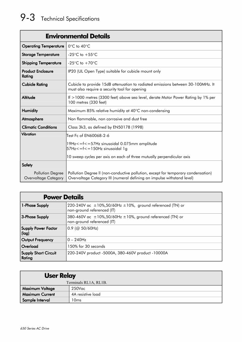
9-3 Technical Specifications
650 Series AC Drive
Environmental DetailsOperating TemperatureOperating TemperatureOperating TemperatureOperating Temperature 0°C to 40°C
Storage TemperatureStorage TemperatureStorage TemperatureStorage Temperature -25°C to +55°C
Shipping TemperatureShipping TemperatureShipping TemperatureShipping Temperature -25°C to +70°C
Product EnclosureProduct EnclosureProduct EnclosureProduct EnclosureRatingRatingRatingRating
IP20 (UL Open Type) suitable for cubicle mount only
Cubicle RatingCubicle RatingCubicle RatingCubicle Rating Cubicle to provide 15dB attenuation to radiated emissions between 30-100MHz. Itmust also require a security tool for opening
AltitudeAltitudeAltitudeAltitude If >1000 metres (3300 feet) above sea level, derate Motor Power Rating by 1% per100 metres (330 feet)
HumidityHumidityHumidityHumidity Maximum 85% relative humidity at 40°C non-condensing
AtmosphereAtmosphereAtmosphereAtmosphere Non flammable, non corrosive and dust free
Climatic ConditionsClimatic ConditionsClimatic ConditionsClimatic Conditions Class 3k3, as defined by EN50178 (1998)
VibrationVibrationVibrationVibration Test Fc of EN60068-2-6
19Hz<=f<=57Hz sinusoidal 0.075mm amplitude57Hz<=f<=150Hz sinusoidal 1g
10 sweep cycles per axis on each of three mutually perpendicular axis
SafetySafetySafetySafety
Pollution DegreeOvervoltage Category
Pollution Degree ll (non-conductive pollution, except for temporary condensation)Overvoltage Category III (numeral defining an impulse withstand level)
Power Details1-Phase Supply1-Phase Supply1-Phase Supply1-Phase Supply 220-240V ac ±10%,50/60Hz ±10%, ground referenced (TN) or
non-ground referenced (IT)
3-Phase Supply3-Phase Supply3-Phase Supply3-Phase Supply 380-460V ac ±10%,50/60Hz ±10%, ground referenced (TN) ornon-ground referenced (IT)
Supply Power FactorSupply Power FactorSupply Power FactorSupply Power Factor(lag)(lag)(lag)(lag)
0.9 (@ 50/60Hz)
Output FrequencyOutput FrequencyOutput FrequencyOutput Frequency 0 – 240Hz
OverloadOverloadOverloadOverload 150% for 30 seconds
Supply Short CircuitSupply Short CircuitSupply Short CircuitSupply Short CircuitRatingRatingRatingRating
220-240V product -5000A, 380-460V product -10000A
User RelayTerminals RL1A, RL1B.
Maximum VoltageMaximum VoltageMaximum VoltageMaximum Voltage 250VacMaximum CurrentMaximum CurrentMaximum CurrentMaximum Current 4A resistive loadSample IntervalSample IntervalSample IntervalSample Interval 10ms

Technical Specifications 9-4
650 Series AC Drive
Electrical RatingsMotor power, output current and input current must not be exceeded under steady stateoperating conditions.Maximum Motor dv/dt = 10,000V/µs. This can be reduced by adding a motor choke in serieswith the motor. Contact Eurotherm Drives for recommended choke details.Local wiring regulations always take precedence. Select cable rated for the drive.The supply must be protected with a fuse (or Type B RCD) rated to the supply cable.
FRAME 1 : 1-Phase (IT/TN), 230V
Input Current @ 5kAInput Current @ 5kAInput Current @ 5kAInput Current @ 5kADriveDriveDriveDrivePowerPowerPowerPower
(kW/hp)(kW/hp)(kW/hp)(kW/hp)Surge CurrentSurge CurrentSurge CurrentSurge Current
peak/rms for 10ms (A)peak/rms for 10ms (A)peak/rms for 10ms (A)peak/rms for 10ms (A)(A)(A)(A)(A)
Output Current @ 40Output Current @ 40Output Current @ 40Output Current @ 40 ooooCCCC(A) ac(A) ac(A) ac(A) ac
Maximum PowerMaximum PowerMaximum PowerMaximum PowerLossLossLossLoss(W)(W)(W)(W)
0.25/0.3 19/12 4.2 1.5 26
0.37/0.5 19/12 6.2 2.2 32
0.55/0.75 20/14 7.9 3.0 41
0.75/1.0 22/15 10.5 4.0 52
FRAME 2 : 1-Phase (IT/TN), 230V
Input Current @ 5kAInput Current @ 5kAInput Current @ 5kAInput Current @ 5kADriveDriveDriveDrivePowerPowerPowerPower
(kW/hp)(kW/hp)(kW/hp)(kW/hp)Surge CurrentSurge CurrentSurge CurrentSurge Current
peak/rms for 10ms (A)peak/rms for 10ms (A)peak/rms for 10ms (A)peak/rms for 10ms (A)(A)(A)(A)(A)
Output Current @ 40Output Current @ 40Output Current @ 40Output Current @ 40 ooooCCCC(A) ac(A) ac(A) ac(A) ac
Maximum PowerMaximum PowerMaximum PowerMaximum PowerLossLossLossLoss(W)(W)(W)(W)
1.1/1.5 24/17 13.8 5.5 65
1.5/2.0 25/18 16.0 7.0 82
FRAME 2 : 3-Phase (IT/TN), 400V
DriveDriveDriveDrivePowerPowerPowerPower
(kW/hp)(kW/hp)(kW/hp)(kW/hp)
Input Current @ 10kAInput Current @ 10kAInput Current @ 10kAInput Current @ 10kA(A)(A)(A)(A)
Output Current @ 40Output Current @ 40Output Current @ 40Output Current @ 40 ooooCCCC(A) ac(A) ac(A) ac(A) ac
Maximum PowerMaximum PowerMaximum PowerMaximum PowerLossLossLossLoss(W)(W)(W)(W)
0.37/0.5 2.5 1.5 26
0.55/0.75 3.3 2.0 32
0.75/1.0 4.1 2.5 40
1.1/1.5 5.9 3.5 55
1.5/2.0 7.5 4.5 61
2.2/3.0 9.4 5.5 70
FRAME 3 : 3-Phase (IT/TN), 200V
DriveDriveDriveDrivePowerPowerPowerPower
(kW/hp)(kW/hp)(kW/hp)(kW/hp)
Input Current @ 10kAInput Current @ 10kAInput Current @ 10kAInput Current @ 10kA(A)(A)(A)(A)
Output Current @ 40Output Current @ 40Output Current @ 40Output Current @ 40 ooooCCCC(A) ac(A) ac(A) ac(A) ac
Maximum PowerMaximum PowerMaximum PowerMaximum PowerLossLossLossLoss(W)(W)(W)(W)
2.2/3.0 14.3 9.6 82
3.0/4 18.1 12.3 108
4.0/5 23.1 16.4 147
FRAME 3 : 3-Phase (IT/TN), 400V
DriveDriveDriveDrivePowerPowerPowerPower
(kW/hp)(kW/hp)(kW/hp)(kW/hp)
Input Current @ 10kAInput Current @ 10kAInput Current @ 10kAInput Current @ 10kA(A)(A)(A)(A)
Output Current @ 40Output Current @ 40Output Current @ 40Output Current @ 40 ooooCCCC(A) ac(A) ac(A) ac(A) ac
Maximum PowerMaximum PowerMaximum PowerMaximum PowerLossLossLossLoss(W)(W)(W)(W)
3.0/4 11.1 6.8 80
4.0/5 13.9 9.0 100
5.5/7.5 18.0 12.0 136
7.5/10 23.6 16.0 180

9-5 Technical Specifications
650 Series AC Drive
Analog Inputs/OutputsTerminals AIN1, AIN2, AOUT1.InputsInputsInputsInputs OutputOutputOutputOutput
RangeRangeRangeRange 0-10V and 0-5V (no sign) set via parameter SIP13 (AIN1)0-10V, 0-5V, 0-20mA or 4-20mA (no sign) set viaparameter SIP23 (AIN2)Absolute maximum input current 25mA in current modeAbsolute maximum input voltage 24V dc in voltage mode
0-10V (no sign)Maximum rated outputcurrent 10mA, with shortcircuit protection
ImpedanceImpedanceImpedanceImpedance Voltage input 20kΩCurrent Input <6V @ 20mA
ResolutionResolutionResolutionResolution 10 bits (1 in 1024) 10 bits (1 in 1024)Dynamic ResponseDynamic ResponseDynamic ResponseDynamic Response Sampled every 10ms Bandwidth 15Hz
Digital InputsTerminals DIN1, DIN2, DIN3, DIN4.
Operating RangeOperating RangeOperating RangeOperating Range 0-5V dc = OFF, 15-24V dc = ON(absolute maximum input voltage ±30V dc)IEC1131 undefined state
15V
5V
0V
24VON
OFF
Input CurrentInput CurrentInput CurrentInput Current 7.5mA @ 24VSample IntervalSample IntervalSample IntervalSample Interval 10ms
Digital OutputsTerminals DOUT2 (DOUT1 is reserved for future models).
Nominal Open Circuit Output VoltageNominal Open Circuit Output VoltageNominal Open Circuit Output VoltageNominal Open Circuit Output Voltage 23V (minimum 19V)
Nominal Output ImpedanceNominal Output ImpedanceNominal Output ImpedanceNominal Output Impedance 33ΩRated Output CurrentRated Output CurrentRated Output CurrentRated Output Current 50mA
Cabling Requirements for EMC CompliancePower Supply CablePower Supply CablePower Supply CablePower Supply Cable Motor CableMotor CableMotor CableMotor Cable Brake Resistor CableBrake Resistor CableBrake Resistor CableBrake Resistor Cable Signal/Control CableSignal/Control CableSignal/Control CableSignal/Control Cable
Cable TypeCable TypeCable TypeCable Type
(for EMC Compliance)(for EMC Compliance)(for EMC Compliance)(for EMC Compliance)Unscreened Screened/armoured Screened/armoured Screened
SegregationSegregationSegregationSegregation From all other wiring(clean)
From all other wiring (noisy) From all other wiring(sensitive)
Length LimitationsLength LimitationsLength LimitationsLength LimitationsWith Internal AC SupplyWith Internal AC SupplyWith Internal AC SupplyWith Internal AC SupplyEMC FilterEMC FilterEMC FilterEMC Filter
Unlimited *25 metres25 metres 25 metres
Length LimitationsLength LimitationsLength LimitationsLength LimitationsWithout Internal ACWithout Internal ACWithout Internal ACWithout Internal ACSupply EMC FilterSupply EMC FilterSupply EMC FilterSupply EMC Filter
Unlimited 25 metres 25 metres 25 metres
Screen to EarthScreen to EarthScreen to EarthScreen to EarthConnectionConnectionConnectionConnection
Both ends Both ends Drive end only
Output ChokeOutput ChokeOutput ChokeOutput Choke300 metresmaximum
* Maximum motor cable length under any circumstances

Technical Specifications 9-6
650 Series AC Drive
Internal Dynamic Braking Circuit (400V only)The dynamic braking circuit is intended for with short term stopping or braking. The Frame 2product is rated for continuous switch operation, however the Frame 3 product is rated for amaximum 30% duty. DC link brake voltage : 750V
Motor PowerMotor PowerMotor PowerMotor Power(kW/Hp)(kW/Hp)(kW/Hp)(kW/Hp)
Brake SwitchBrake SwitchBrake SwitchBrake SwitchPeak CurrentPeak CurrentPeak CurrentPeak Current
(A)(A)(A)(A)
Brake SwitchBrake SwitchBrake SwitchBrake SwitchContinuous CurrentContinuous CurrentContinuous CurrentContinuous Current
(A)(A)(A)(A)
Peak BrakePeak BrakePeak BrakePeak BrakeDissipationDissipationDissipationDissipation(kW/Hp)(kW/Hp)(kW/Hp)(kW/Hp)
Minimum BrakeMinimum BrakeMinimum BrakeMinimum BrakeResistor ValueResistor ValueResistor ValueResistor Value
((((ΩΩΩΩ))))Frame 2 : 3 Phase (IT/TN), 400VFrame 2 : 3 Phase (IT/TN), 400VFrame 2 : 3 Phase (IT/TN), 400VFrame 2 : 3 Phase (IT/TN), 400V
0.37/0.5 1.5 1.5 1.1/1.5 5000.55/0.75 1.5 1.5 1.1/1.5 5000.75/1.0 1.5 1.5 1.1/1.5 5001.1/1.5 1.5 1.5 1.1/1.5 5001.5/2.0 3.75 3.75 2.8/3.75 2002.2/3.0 3.75 3.75 2.8/3.75 200
Frame 3 : 3 Phase (IT/TN), 400VFrame 3 : 3 Phase (IT/TN), 400VFrame 3 : 3 Phase (IT/TN), 400VFrame 3 : 3 Phase (IT/TN), 400V3.0/4 7.5 2.3 5.6/7.5 1004.0/5 7.5 2.3 5.6/7.5 100
5.5/7.5 13.5 4.0 10/13.4 567.5/10 13.5 4.0 10/13.4 56
External Brake Resistor (400V only)All 650 units are supplied without braking resistors. The dynamic brake switch terminalsallow easy connection to an external resistor. These resistors should be mounted on a heatsink(back panel) and covered to prevent injury from burning.
Recommended Brake ResistorsThe following brake resistors are avialable from Eurotherm Drives:Brake Resistor Value : Frame 2 : 200Ω, 100W - CZ467714; 500Ω, 60W - CZ467715
Frame 3 : 56Ω, 500W - CZ467716; 100Ω, 200W - CZ467717
Alternative Brake Resistor SelectionBrake resistor assemblies must be rated to absorb both peak braking power during deceleration and the average powerover the repeated cycles.
Peak braking power P0 0055 n n
tW1
22
2
b=
× −. ( )( )pk
× J
J - total inertia (kgm2)n1 - initial speed (rpm)
Average braking power PPtavpk
c= x tb n2 - final speed (rpm)
tb - braking time (s)tc - cycle time (s)
Obtain information on the peak power rating and the average power rating of the resistors from the resistormanufacturer. If this information is not available, a large safety margin must be incorporated to ensure that the resistorsare not overloaded. By connecting these resistors in series and in parallel the braking capacity can be selected for theapplication.IMPORTANT: The minimum resistance of the combination and maximum dc link voltage must be as
specified.Resistor Derating Graph
020406080
100120
0 25 50 75 100 125 150 175 200Ambient Temp (C)
% of Rated Power
chassis mountedfree air

9-7 Technical Specifications
650 Series AC Drive
Supply Harmonic Analysis (filtered)Assumptions: 5kA short circuit supply capability at 230V, equivalent to 146µH supply impedance
10kA short circuit supply capability at 400V, equivalent to 127µH supply impedance
THD(V) x 100 = =∑ Q
Q
h2
1n
h 40
=h 2
%
where Q1n is the rated rms value of the fundamental voltage of the supply transformer.The results conform to stage 1 and stage 2 of the Engineering Recommendation G.5/4 February 2001,Classification ‘C’: Limits for Harmonics in the UK Electricity Industry.
Drive Type 650 Motor Power (kW) 0.25 0.37 0.55 0.75 1.1 1.5 0.37 0.55 0.75 1.1 1.5 2.2 3.0 4.0 5.5 7.5 Fundamental Voltage (V) 230 230 230 230 230 230 400 400 400 400 400 400 400 400 400 400 Typical Motor Efficiency % 85 85 85 85 85 85 85 85 85 85 85 85 85 85 85 85
Harmonic No. RMS Current (A)1 7.4 7.5 7.8 8.2 9.0 10.3 0.6 1.0 1.3 1.9 2.6 3.8 5.2 6.9 9.5 12.9
3 1.4 0.2 1.9 2.2 2.9 3.9 0.0 0.0 0.0 0.0 0.0 0.0 0.0 0.0 0.0 0.0
5 2.9 0.4 4.4 4.6 4.8 5.2 0.6 0.9 1.2 1.8 2.4 3.5 4.7 6.2 8.3 11.1
7 1.1 0.5 1.9 2.0 2.3 2.5 0.6 0.9 1.2 1.7 2.3 3.3 4.3 5.5 7.3 9.5
9 0.2 0.2 0.2 0.3 0.4 0.4 0.0 0.0 0.0 0.0 0.0 0.0 0.0 0.0 0.0 0.0
11 0.1 0.1 0.2 0.2 0.2 0.3 0.5 0.8 1.0 1.5 1.9 2.6 3.3 3.9 4.8 5.7
13 0.0 0.1 0.1 0.1 0.1 0.1 0.0 0.7 0.9 1.3 1.6 2.2 2.7 3.0 3.5 3.9
15 0.1 0.0 0.1 0.1 0.1 0.1 0.4 0.0 0.0 0.0 0.0 0.0 0.0 0.0 0.0 0.0
17 0.0 0.1 0.0 0.0 0.0 0.1 0.4 0.6 0.7 1.0 1.1 1.4 1.6 1.5 1.4 1.2
19 0.0 0.0 0.0 0.0 0.0 0.1 0.0 0.5 0.6 0.9 0.9 1.1 1.1 0.9 0.8 0.7
21 0.0 0.0 0.0 0.0 0.0 0.1 0.3 0.0 0.0 0.0 0.0 0.0 0.0 0.0 0.0 0.0
23 0.0 0.0 0.0 0.0 0.0 0.0 0.2 0.3 0.4 0.6 0.5 0.5 0.4 0.3 0.5 0.7
25 0.0 0.0 0.0 0.0 0.0 0.0 0.0 0.3 0.3 0.4 0.3 0.3 0.2 0.4 0.5 0.7
27 0.0 0.0 0.0 0.0 0.0 0.0 0.1 0.0 0.0 0.0 0.0 0.0 0.0 0.0 0.0 0.0
29 0.0 0.0 0.0 0.0 0.0 0.0 0.1 0.2 0.2 0.2 0.1 0.2 0.3 0.4 0.4 0.4
31 0.0 0.0 0.0 0.0 0.0 0.0 0.0 0.1 0.1 0.1 0.1 0.2 0.3 0.3 0.3 0.3
33 0.0 0.0 0.0 0.0 0.0 0.0 0.1 0.0 0.0 0.0 0.0 0.0 0.0 0.0 0.0 0.0
35 0.0 0.0 0.0 0.0 0.0 0.0 0.0 0.1 0.1 0.1 0.1 0.2 0.2 0.2 0.2 0.3
37 0.0 0.0 0.0 0.0 0.0 0.0 0.0 0.1 0.1 0.1 0.1 0.2 0.1 0.1 0.2 0.3
39 0.0 0.0 0.0 0.0 0.0 0.0 0.0 0.0 0.0 0.0 0.0 0.0 0.0 0.0 0.0 0.0
40 0.0 0.0 0.0 0.0 0.0 0.0 0.0 0.0 0.0 0.0 0.0 0.0 0.0 0.0 0.0 0.0
Total RMS Current (A) 8.2 7.5 9.3 9.9 10.9 12.5 1.4 2.1 2.8 4.0 5.1 7.2 9.5 12.0 15.8 20.8 THD (V) % 0.35
590.09
720.54
260.57
330.62
770.70
550.15
610.21
580.27
760.38
590.43
930.57
450.69
940.81
110.98
991.2110

Technical Specifications 9-8
650 Series AC Drive
Supply Harmonic Analysis (unfiltered)Assumptions: 5kA short circuit supply capability at 230V, equivalent to 146µH supply impedance
10kA short circuit supply capability at 400V, equivalent to 127µH supply impedance
THD(V) x 100 = =∑ Q
Q
h2
1n
h 40
=h 2
%
where Q1n is the rated rms value of the fundamental voltage of the supply transformer.The results conform to stage 1, stage 2 and stage 3 of the Engineering Recommendation G.5/3 September1976, Classification ‘C’: Limits for Harmonics in the UK Electricity Industry.
Drive Type 650 Motor Power (kW) 0.25 0.37 0.55 0.75 1.1 1.5 0.37 0.55 0.75 1.1 1.5 2.2 3.0 4.0 5.5 7.5
Fundamental Voltage (V) 230 230 230 230 230 230 400 400 400 400 400 400 400 400 400 400
Typical Motor Efficiency % 85 85 85 85 85 85 85 85 85 85 85 85 85 85 85 85
Harmonic No. RMS Current (A)1 1.3 2.0 2.9 3.9 5.7 7.8 0.6 0.9 1.3 1.9 2.6 3.8 5.2 6.9 9.5 12.7
3 1.3 1.9 2.9 3.8 5.5 7.4 0.0 0.0 0.0 0.0 0.0 0.0 0.0 0.0 0.0 0.0
5 1.2 1.9 2.7 3.5 5.0 6.7 0.6 0.9 1.2 1.8 2.4 3.6 4.7 6.3 8.4 11.0
7 1.1 1.7 2.5 3.1 4.4 5.4 0.6 0.9 1.2 1.7 2.3 3.3 4.3 5.7 7.4 9.5
9 1.1 1.6 2.2 2.7 3.7 4.6 0.0 0.0 0.0 0.0 0.0 0.0 0.0 0.0 0.0 0.0
11 1.0 1.4 1.9 2.2 2.9 3.4 0.5 0.8 1.0 1.5 1.9 2.6 3.3 4.2 4.9 5.8
13 0.8 1.2 1.6 1.6 2.1 2.3 0.5 0.7 0.9 1.3 1.6 2.2 2.7 3.4 3.7 4.0
15 0.7 1.0 1.3 1.2 1.4 1.4 0.0 0.0 0.0 0.0 0.0 0.0 0.0 0.0 0.0 0.0
17 0.6 0.8 1.0 0.8 0.8 0.7 0.4 0.6 0.7 0.9 1.2 1.5 1.6 1.9 1.5 1.3
19 0.5 0.7 0.7 0.4 0.4 0.3 0.4 0.5 0.6 0.8 0.9 1.1 1.1 1.3 0.8 0.7
21 0.4 0.5 0.5 0.2 0.2 0.4 0.0 0.0 0.0 0.0 0.0 0.0 0.0 0.0 0.0 0.0
23 0.3 0.3 0.3 0.2 0.3 0.4 0.3 0.4 0.4 0.5 0.5 0.5 0.4 0.4 0.5 0.7
25 0.2 0.2 0.1 0.2 0.3 0.4 0.2 0.3 0.3 0.3 0.4 0.3 0.2 0.3 0.5 0.7
27 0.1 0.1 0.1 0.2 0.3 0.3 0.0 0.0 0.0 0.0 0.0 0.0 0.0 0.0 0.0 0.0
29 0.1 0.1 0.1 0.2 0.2 0.2 0.1 0.2 0.2 0.2 0.1 0.2 0.2 0.3 0.4 0.4
31 0.0 0.1 0.1 0.1 0.1 0.1 0.1 0.1 0.1 0.1 0.1 0.2 0.3 0.3 0.3 0.3
33 0.0 0.1 0.1 0.1 0.1 0.2 0.0 0.0 0.0 0.0 0.0 0.0 0.0 0.0 0.0 0.0
35 0.0 0.1 0.1 0.1 0.1 0.2 0.1 0.1 0.1 0.1 0.1 0.2 0.2 0.2 0.2 0.3
37 0.1 0.1 0.1 0.1 0.1 0.1 0.0 0.1 0.1 0.1 0.1 0.2 0.2 0.1 0.2 0.2
39 0.0 0.1 0.1 0.1 0.1 0.1 0.0 0.0 0.0 0.0 0.0 0.0 0.0 0.0 0.0 0.0
40 0.0 0.0 0.0 0.0 0.0 0.0 0.0 0.0 0.0 0.0 0.0 0.0 0.0 0.0 0.0 0.0
Total RMS Current (A) 3.2 4.8 6.7 8.3 11.7 15.3 1.5 2.1 2.8 4.0 5.1 7.4 9.5 12.4 16.0 20.6 THD (V) % 0.56
330.80
161.03
401.09
441.46
111.77
780.16
340.22
090.28
170.35
690.44
440.58
860.71
070.88
961.01
271.2138

10-1 Certification for the Drive
650 Series AC Drive
9 CERTIFICATION FOR THE DRIVERequirements for EMC Compliance
Earthing RequirementsIMPORTANT: Protective earthing always takes precedence over EMC earthing.
Protective Earth (PE) ConnectionsNote: In accordance with installations to EN60204, only one protective earth conductor is
permitted at each protective earth terminal contacting point.
Local wiring regulations may require the protective earth connection of the motor to beconnected locally, i.e. not as specified in these instructions. This will not cause shieldingproblems because of the relatively high RF impedance of the local earth connection.
EMC Earth ConnectionsFor compliance with EMC requirements, the “0V/signal ground” is to be separately earthed.When a number of units are used in a system, these terminals should be connected together at asingle, local earthing point.
Control and signal cables connections should be made with screeened cables, with the screenconnected only at the VSD end. However, if high frequency noise is still a problem, earth screenat the non VSD end via a 0.1µF capacitor.
Note: Connect the screen (at the VSD end) to the VSD protective earth point, and not to thecontrol board terminals.
Requirements for UL ComplianceSolid-State Motor Overload ProtectionThese devices provide Class 10 motor overload protection. The maximum internal overloadprotection level (current limit) is 150% for 30 seconds.
An external motor overload protective device must be provided by the installer where the motorhas a full-load ampere rating of less than 50% of the drive output rating.
Short Circuit RatingThe following drives are suitable for use on a circuit capable of delivering not more than:
220-240V product - 5000 RMS Symmetrical Amperes380-460V product -10000 RMS Symmetrical Amperes
Solid-State Short-Circuit ProtectionThese devices are provided with Solid-State Short-Circuit (output) Protection. Branch circuitprotection requirements must be in accordance with the latest edition of the National ElectricalCode NEC/NFPA-70.
Recommended Branch Circuit ProtectionIt is recommended that UL Listed (JDDZ) non-renewable cartridge fuses, Class K5 or H; or ULListed (JDRX) renewable cartridge fuses, Class H, are installed upstream of the drive.
Motor Base FrequencyThe motor base frequency rating is 240Hz maximum.
Field Wiring Temperature RatingUse 75°C Copper conductors only.
Field Wiring Terminal MarkingsFor correct field wiring connections that are to be made to each terminal refer to Chapter 3:“Installing the Drive” - Wiring Guidelines.

Certification for the Drive 10-2
650 Series AC Drive
Terminal Tightening TorqueRefer to Chapter 3: “Installing the Drive” – Terminal Tightening Torque.
Terminal/Wire SizesNorth American wire sizes (AWG) are based on NEC/NFPA-70 for ampacities of thermoplastic-insulated (75ºC) copper conductors.
Power input and output wire sizes should allow for an ampacity of 125% of the rated input andoutput amperes for motor branch-circuit conductors as specified in NEC/NFPA-70. Refer toChapter 3: “Installing the Drive” – Terminal Block Acceptance Sizes.
Input Fuse RatingsIf fitted, fuses should be in accordance with NEC/NFPA-70.
FRAME 1 : 1-Phase (IT/TN), 230VInput Current @ 5kAInput Current @ 5kAInput Current @ 5kAInput Current @ 5kADrive PowerDrive PowerDrive PowerDrive Power
(kW/hp)(kW/hp)(kW/hp)(kW/hp) (A)(A)(A)(A)
Supply Fuse Rating (A)Supply Fuse Rating (A)Supply Fuse Rating (A)Supply Fuse Rating (A)10 x 38mm10 x 38mm10 x 38mm10 x 38mm
0.25/0.3 4.2 100.37/0.5 6.2 100.55/0.75 7.9 100.75/1.0 10.5 15
FRAME 2 : 1-Phase (IT/TN), 230VInput Current @ 5kAInput Current @ 5kAInput Current @ 5kAInput Current @ 5kADrive PowerDrive PowerDrive PowerDrive Power
(kW/hp)(kW/hp)(kW/hp)(kW/hp) (A)(A)(A)(A)
Supply Fuse Rating (A)Supply Fuse Rating (A)Supply Fuse Rating (A)Supply Fuse Rating (A)10 x 38mm10 x 38mm10 x 38mm10 x 38mm
1.1/1.5 13.8 201.5/2.0 16.0 20
FRAME 2 : 3-Phase (IT/TN), 400VDrive PowerDrive PowerDrive PowerDrive Power
(kW/hp)(kW/hp)(kW/hp)(kW/hp)Input Current @ 10kAInput Current @ 10kAInput Current @ 10kAInput Current @ 10kA
(A)(A)(A)(A)Supply Fuse Rating (A)Supply Fuse Rating (A)Supply Fuse Rating (A)Supply Fuse Rating (A)
10 x 38mm10 x 38mm10 x 38mm10 x 38mm0.37/0.5 2.5 100.55/0.75 3.3 100.75/1.0 4.1 101.1/1.5 5.9 101.5/2.0 7.5 102.2/3.0 9.4 15
FRAME 3 : 3-Phase (IT/TN), 200VDrive PowerDrive PowerDrive PowerDrive Power
(kW/hp)(kW/hp)(kW/hp)(kW/hp)Input Current @ 10kAInput Current @ 10kAInput Current @ 10kAInput Current @ 10kA
(A)(A)(A)(A)Supply Fuse Rating (A)Supply Fuse Rating (A)Supply Fuse Rating (A)Supply Fuse Rating (A)
10 x 38mm10 x 38mm10 x 38mm10 x 38mm2.2/3.0 9.6 153.0/4 12.3 204.0/5 16.4 20
FRAME 3 : 3-Phase (IT/TN), 400VDrive PowerDrive PowerDrive PowerDrive Power
(kW/hp)(kW/hp)(kW/hp)(kW/hp)Input Current @ 10kAInput Current @ 10kAInput Current @ 10kAInput Current @ 10kA
(A)(A)(A)(A)Supply Fuse Rating (A)Supply Fuse Rating (A)Supply Fuse Rating (A)Supply Fuse Rating (A)
10 x 38mm10 x 38mm10 x 38mm10 x 38mm3.0/4 11.1 154.0/5 13.9 20
5.5/7.5 18.0 257.5/10 23.6 30
Field Grounding TerminalsThe field grounding terminals are identified with the International Grounding Symbol(IEC Publication 417, Symbol 5019).
Operating Ambient TemperatureDevices are considered acceptable for use in a maximum ambient temperature of 40°C (can bederated up to 50°C).

10-3 Certification for the Drive
650 Series AC Drive
European Directives and the CE Mark
CE Marking for Low Voltage DirectiveWhen installed in accordance with this manual, the 650 Series AC Drive is CE marked byEurotherm Drives Ltd in accordance with the low voltage directive (S.I. No. 3260 implementsthis LVD directive into UK law). An EC Declaration of Conformity (low voltage directive) isincluded at the end of this chapter.
CE Marking for EMC - Who is Responsible?Note: The specified EMC emission and immunity performance of this unit can only be achieved
when the unit is installed to the EMC Installation Instructions given in this manual.
According to S.I. No. 2373 which implements the EMC directive into UK law, the requirementfor CE marking this unit falls into two categories:
1. Where the supplied unit has an intrinsic/direct function to the end user, then the unit isclassed as relevant apparatus. In this situation the responsibility for certification rests withEurotherm Drives. The Declaration of Conformity is included at the end of this Chapter.
2. Where the supplied unit is incorporated into a higher system/apparatus or machine whichincludes (at least) the motor, cable and a driven load but is unable to function without thisunit, then the unit is classed as a component. In this circumstance, the reponsibility restswith the manufacturer/supplier/installer of the system/apparatus/machine.
EMC Compliance
All ModelsAll models are compliant with BS EN61800-3.
Radiated EmissionsRadiated EmissionsRadiated EmissionsRadiated Emissions EN50081-1(1992) and EN61800-3 unrestricted distribution when mounted inside thespecified cubicle, see above. Control and motor cables must be screened and correctlyfitted with glands where they exit the cubicle. Control 0V must be connected toprotective earth/ground.
ImmunityImmunityImmunityImmunity EN50082-1 (1997), EN61800-3 (1997), EN61000-6-2 (1999)
FRAME 1 & 2: 1-Phase (TN only),
Conducted EmissionsConducted EmissionsConducted EmissionsConducted Emissions EN50081-1(1992), EN61800-3 unrestricted distribution,maximum motor cable length: 25m
FRAME 2 & 3 : 3-Phase (TN only)
Conducted EmissionsConducted EmissionsConducted EmissionsConducted Emissions EN50081-2(1993), EN61800-3 restricted distributionmaximum motor cable length: 25m

Certification for the Drive 10-4
650 Series AC Drive
Certificates650 0.25 -1.5KW 200V
EC DECLARATIONS OF CONFORMITY
Date CE marked first applied: 26/07/2001
Issued for EMC Directive Low Voltage Directive The drive is CEcompliancewith the EMCDirective whenthe unit is usedas relevantapparatus.
In accordance with the EEC Directive89/336/EEC and amended by 92/31/EEC and93/68/EEC, Article 10 and Annex 1, (EMC
DIRECTIVE)
We Eurotherm Drives Limited, address asbelow, declare under our sole responsibility
that the above Electronic Products wheninstalled and operated with reference to the
instructions in the Product Manual (providedwith each piece of equipment) is in accordance
with the relevant clauses from the followingstandards:-
BSEN50081-1 (1997), BSEN50082-1#(1997), BSEN61800-3 (1996) and
EN61000-6-2 (1999)
In accordance with the EEC Directive73/23/EEC and amended by 93/68/EEC,
Article 13 and Annex III, (LOW VOLTAGEDIRECTIVE)
We Eurotherm Drives Limited, address asbelow, declare under our sole responsibility
that the above Electronic Products wheninstalled and operated with reference to the
instructions in the Product Manual (providedwith each piece of equipment), is in accordance
with the following standard :-
EN50178 (1998)
marked inaccordance withthe low voltagedirective forelectricalequipment andappliances in thevoltage rangewhen installedcorrectly.
MANUFACTURERS DECLARATIONSThis is EMC Declaration Machinery Directive Since theprovided to aidyourjustification forEMCcompliancewhen the unitis used as acomponent.
We Eurotherm Drives Limited, address asbelow, declare under our sole responsibility
that the above Electronic Products wheninstalled and operated with reference to the
instructions in the Product Manual (providedwith each piece of equipment) is in accordancewith the relevant clauses from the following
standards:-BSEN50081-1 (1997), BSEN50082-1#
(1997), BSEN61800-3 (1996) andEN61000-6-2 (1999)
The above Electronic Products are componentsto be incorporated into machinery and may not
be operated alone.The complete machinery or installation usingthis equipment may only be put into service
when the safety considerations of the Directive89/392/EEC are fully adhered to.
Particular reference should be made toEN60204-1 (Safety of Machinery - Electrical
Equipment of Machines).All instructions, warnings and safety
information of the Product Manual must beadhered to.
potential hazardsare mainlyelectrical ratherthan mechanical,the drive does notfall under themachinerydirective.However, we dosupply amanufacturer'sdeclaration forwhen the drive isused(as acomponent) inmachinery.
Dr Martin Payn (Conformance Officer)
# Compliant with these immunity standards without specified EMC filters.
EUROTHERM DRIVES LIMITED An Invensys CompanyNEW COURTWICK LANE, LITTLEHAMPTON, WEST SUSSEX BN17 7RZTELEPHONE: +44(0)1903 737000 FAX: +44(0)1903 737100Registered Number: 1159876 England. Registered Office: Invensys House, Carlisle Place, London, SW1P 1BX
File Name: C:\Documents and Settings\jrich\My Documents\Temp docs\hp467607.919 © 1999 EUROTHERM DRIVES LIMITED
ISS: DATE DRN: J.Mc CHKD: MP DRAWING NUMBER: HK467607.919
A 20/01/01
EUROTHERMDRIVES
TITLE:
Declarations of ConformitySHT 4
OF
1 SHTS

10-5 Certification for the Drive
650 Series AC Drive
650 0.37 -7.5KW 400V
EC DECLARATIONS OF CONFORMITY
Date CE marked first applied: 26/07/2001
Issued for EMC Directive Low Voltage Directive The drive is CEcompliancewith the EMCDirective whenthe unit is usedas relevantapparatus.
In accordance with the EEC Directive89/336/EEC and amended by 92/31/EEC and93/68/EEC, Article 10 and Annex 1, (EMC
DIRECTIVE)
We Eurotherm Drives Limited, address asbelow, declare under our sole responsibility
that the above Electronic Products wheninstalled and operated with reference to the
instructions in the Product Manual (providedwith each piece of equipment) is in accordance
with the relevant clauses from the followingstandards:-
BSEN50081-1 (1997), BSEN50082-1#(1997), BSEN61800-3 (1996) and
EN61000-6-2 (1999)
In accordance with the EEC Directive73/23/EEC and amended by 93/68/EEC,
Article 13 and Annex III, (LOW VOLTAGEDIRECTIVE)
We Eurotherm Drives Limited, address asbelow, declare under our sole responsibility
that the above Electronic Products wheninstalled and operated with reference to the
instructions in the Product Manual (providedwith each piece of equipment), is in accordance
with the following standard :-
EN50178 (1998)
marked inaccordance withthe low voltagedirective forelectricalequipment andappliances in thevoltage rangewhen installedcorrectly.
MANUFACTURERS DECLARATIONSThis is EMC Declaration Machinery Directive Since theprovided to aidyourjustification forEMCcompliancewhen the unitis used as acomponent.
We Eurotherm Drives Limited, address asbelow, declare under our sole responsibility
that the above Electronic Products wheninstalled and operated with reference to the
instructions in the Product Manual (providedwith each piece of equipment) is in accordancewith the relevant clauses from the following
standards:-BSEN50081-1 (1997), BSEN50082-1#
(1997), BSEN61800-3 (1996) andEN61000-6-2 (1999)
The above Electronic Products are componentsto be incorporated into machinery and may not
be operated alone.The complete machinery or installation usingthis equipment may only be put into service
when the safety considerations of the Directive89/392/EEC are fully adhered to.
Particular reference should be made toEN60204-1 (Safety of Machinery - Electrical
Equipment of Machines).All instructions, warnings and safety
information of the Product Manual must beadhered to.
potential hazardsare mainlyelectrical ratherthan mechanical,the drive does notfall under themachinerydirective.However, we dosupply amanufacturer'sdeclaration forwhen the drive isused(as acomponent) inmachinery.
Dr Martin Payn (Conformance Officer)
# Compliant with these immunity standards without specified EMC filters.
EUROTHERM DRIVES LIMITED An Invensys CompanyNEW COURTWICK LANE, LITTLEHAMPTON, WEST SUSSEX BN17 7RZTELEPHONE: +44(0)1903 737000 FAX: +44(0)1903 737100Registered Number: 1159876 England. Registered Office: Invensys House, Carlisle Place, London, SW1P 1BX
File Name: C:\Documents and Settings\jrich\My Documents\Temp docs\hp467607.919 © 1999 EUROTHERM DRIVES LIMITED
ISS: DATE DRN: J.Mc CHKD: MP DRAWING NUMBER: HK467607.919
A 20/01/01
EUROTHERMDRIVES
TITLE:
Declarations of ConformitySHT 5
OF
1 SHTS

Serial Communications 11-1
650 Series AC Drive
5 SERIAL COMMUNICATIONS
Connection to the P3 PortIMPORTANT: The drive MUST be earthedThe drive MUST be earthedThe drive MUST be earthedThe drive MUST be earthed. Failure to do so could damage your communications ports.
The port is an un-isolated RS232, 19200 Baud. The P3 port is located under the terminal coverand is used only by the Remote Keypad.
P3 PortA standard P3 lead is used to connect to the drive.
1 2 3 4
P3 Port PinP3 Port PinP3 Port PinP3 Port Pin LeadLeadLeadLead SignalSignalSignalSignal
1 Black 0V
2 Red 5V
3 Green TX
4 Yellow RX
Note: There is 5V present on pin 2 of the P3 port - do not connect this to your PC.

12-1 Applications
650 Series AC Drive
12 APPLICATIONS
The Default ApplicationThe drive is supplied with 6 Applications, Application 0 to Application 5. Each Applicationrecalls a pre-programmed structure of internal links when it is loaded.
• Application 0 will not control a motor. Loading Application 0 removes all internal links.
• Application 1 is the factory default application, providing for basic speed control
• Application 2 supplies speed control using a manual or auto setpoint
• Application 3 supplies speed control using preset speeds
• Application 4 is a set-up providing speed control with Raise/Lower Trim
• Application 5 supplies speed control with Run Forward/Run Reverse
IMPORTANT: Parameter values are not changed by loading a new Application. Refer to Chapter 4: TheKeypad – Special Menu Features to reset the drive to factory default values which aresuitable for most applications.
How to Load an ApplicationIn the menu, go to and press the key.
The Applications are stored in this menu.
Use the keys to select the appropriate Application by number.
Press the key to load the Application.
Application Description
Control Wiring for Applications
10k SpeedSetpoint
****
Terminal10987654321
Control
RL1ARL1B User Relay
V A
default source = A
DIN4/DOUT2DIN3
DIN1+24VAOUT1+10V REFAIN2AIN10V
DIN2
Not StopJog
Run+24VAOUT1+10V REFFeedbackSetpoint0V
Direction
ResetLower
Run+24VAOUT1+10V REFnot usednot used0V
Raise
Preset 0
Preset SelectPreset Select
Run
AOUT1+10V REF
Preset Select
+24V
Preset 00V
Manual Setpoint
DirectionSelect
Manual Run+24VAOUT1+10V REFAuto Setpoint
0V
Auto Run
Manual/Auto Presets Raise/Lower PID
HealthHealthHealthHealth
Not StopJog
Run+24VAOUT1+10V REFFeedbackSetpoint0V
Direction
Basic SpeedControl
(default)
HealthRL1ARL1B
APPLICATION 1 APPLICATION 2 APPLICATION 3 APPLICATION 4 APPLICATION 5
normally open contact (relay)
2-position switch
normally open push-button
normally closed push-button
Key to Application Diagrams
DEFAULT

Applications 12-2
650 Series AC Drive
Application 1 : Basic Speed ControlAp
plic
atio
n 1:
Ital
ic te
xt in
dica
tes
Def
ault
ID
EAL
FOR
GEN
ERA
L PU
RPO
SE A
PPLI
CA
TIO
NS,
CO
NST
AN
T TO
RQ
UE
AN
D V
AR
IAB
LE T
OR
QU
E
P1 A
PPLI
CATI
ON
= 1
p1A
pplic
atio
np2
Max
spe
edp3
Min
spe
edp4
Acc
el ti
me
p5D
ecel
tim
ep6
Mot
or ra
ted
curr
ent
p7B
ase
freq
uenc
yp8
Jog
setp
oint
p9St
op m
ode
p11
V/F
shap
ep1
2H
VAC
ratin
gsp1
3Fi
xed
boos
t, (V
F on
ly)
p99
Pass
wor
d
STA
ND
AR
D P
AR
AM
ETER
S
Basi
c Sp
eed
Con
trol
Spee
d
Freq
uenc
y
Hz
Spee
d Se
tpt
%D
C L
ink
Volts
VM
otor
Cur
rent
A
DIA
GN
OST
ICS
12345678910
0V
AIN
1
AIN
2
+10V
REF
AO
UT1
+24V
DIN
1
DIN
2
DIN
3
DIN
4/D
OU
T2
REF
MIN
/MA
X S
PE
ED
RA
MP
P2 M
AX
SPEE
D
P3 M
IN S
PEED
CU
RR
ENT
LIM
IT
RE
FER
EN
CE
SE
LEC
T
P8 J
OG
SPD
P4 A
CC
EL T
IME
P5 D
ECEL
TIM
E
PWM
CO
NTR
OL
V/F
SHAP
ING
CT
VT
V
FVF
I FD
BK
VF
SP
EE
D D
EM
AN
D
STAR
T
JOG
FWD
/REV
STO
P Feed
back
4-20
mA
FWD
/RE
V
P9 S
TOP
MO
DE
RL1
A
RL1
BU
ser
Rel
ayR
0 N
ON
E1
HEA
LTH
2 TR
IPP
ED
3 R
UN
NIN
G4
AT
ZER
O5
AT
SP
EE
D
OP3
1RE
LAY
IP13
AIN
1 TY
PE
SE
QU
EN
CIN
G L
OG
IC
OP2
1D
IGIO
2
0 =
CO
NST
AN
T TO
RQ
UE
1 =
VA
RIA
BLE
TO
RQ
UE
P7B
ASE
FR
EQ
P13
V B
OO
ST
P11
V/F
SH
APE
50/6
0Hz
bas
e fr
eque
ncy
0 0
-10V
1 0
-5V
IP23
AIN
2 TY
PE
0 0
-10V
1 0
-5V
2 0
-20m
A3
4-2
0mA
0 N
ON
E1
DEM
AN
D%
2 C
UR
RE
NT%
3 P
ID E
RR
OR
%4
RA
ISE
/LO
WE
R%
OP0
1A
NO
UT
5 A
T S
PE
ED
0 N
ON
E1
HE
ALT
H2
TRIP
PE
D3
RU
NN
ING
4 A
T ZE
RO
P6 I
NO
MIN
AL
Spee
dM
eter
(at d
efau
lt1
setti
ng)

12-3 Applications
650 Series AC Drive
Application 2 : Auto/Manual Control
Ital
ic te
xt in
dica
tes
Def
ault
Auto
/Man
ual C
ontro
l I
DEA
L FO
R A
UTO
MA
TIC
CO
NTR
OL
APP
LIC
ATI
ON
SW
ITH
LIM
IT S
WIT
CH
ES O
R P
RO
XIM
ITY
TRA
NSD
UC
ERS
P1 A
PPLI
CATI
ON
= 2
p1A
pplic
atio
np2
Max
spe
edp3
Min
spe
edp4
Acc
el ti
me
p5D
ecel
tim
ep6
Mot
or ra
ted
curr
ent
p7B
ase
freq
uenc
yp8
Jog
setp
oint
p9St
op m
ode
p11
V/F
shap
ep1
2H
VAC
ratin
gsp1
3Fi
xed
boos
t, (V
F on
ly)
p99
Pass
wor
d
STA
ND
AR
D P
AR
AM
ETER
SAp
plic
atio
n 2:
AUTO
MAT
IC
Pum
p
Auto
/ M
anua
l Sel
ecto
rAu
toSp
eed
Ref
eren
ce
Leve
lLi
mit
Switc
h
Leve
l Sen
sor
LEVE
L C
ON
TRO
L
MIN
/MAX
SPE
EDR
AMP
P2 M
AX
SPEE
D
P3 M
IN S
PEED
CU
RR
ENT
LIM
IT
P4 A
CC
EL T
IME
P5 D
ECEL
TIM
E
PWM
CO
NTR
OL
V/F
SHAP
ING
CT
VT
V
FVF
I FD
BK
VF
SPEE
D D
EMAN
D
FWD
/REV
RL1
A
RL1
BU
ser
Rel
ayR
0 N
ON
E1
HEA
LTH
2 TR
IPPE
D3
RU
NN
ING
4 A
T ZE
RO
5 A
T SP
EED
OP3
1R
ELA
Y0
= C
ON
STA
NT
TOR
QU
E1
= VA
RIA
BLE
TOR
QU
E
P7B
ASE
FR
EQ
P13
V B
OO
ST
P11
V/F
SH
APE
50/6
0Hz
bas
e fr
eque
ncy
3 R
UN
NIN
G
5 A
T SP
EED
12345678910
0V
AIN1
AIN2
+10V
REF
AO
UT1
+24V
DIN
1
DIN
2
DIN
3
DIN
4/D
OU
T2
AUTO
REF
MAN
.
REF
REF
SEL
ECT
AUTO
RU
N
MAN
UAL
RU
N
MAN
UAL
/AU
TO
FWD
/ R
EV
RU
N S
ELEC
T
IP23
AIN
2 TY
PE
0 0
-10V
1 0
-5V
2 0
-20m
A3
4-2
0mA
IP13
AIN
1 TY
PE
0 0
-10V
1 0
-5V
P6 I
RA
TED
Freq
uenc
y
Hz
Spee
d Se
tpt
%D
C L
ink
Volts
VM
otor
Cur
rent
A
DIA
GN
OST
ICS
Spee
dM
eter
(at d
efau
lt1
setti
ng)
0 N
ON
E1
HEA
LTH
2 TR
IPPE
D
4 A
T ZE
RO
SEQ
UEN
CIN
G L
OG
IC
OP2
1D
IGIO
2

Applications 12-4
650 Series AC Drive
Application 3 Preset Speeds
Pres
et S
peed
s I
DEA
L FO
R A
PPLI
CA
TIO
NS
REQ
UIR
ING
MU
LTIP
LE D
ISC
RET
E SP
EED
LEV
ELS
P1 A
PPLI
CATI
ON
= 3
p1A
pplic
atio
np2
Max
spe
edp3
Min
spe
edp4
Acc
el ti
me
p5D
ecel
tim
ep6
Mot
or ra
ted
curr
ent
p7B
ase
freq
uenc
yp8
Jog
setp
oint
p9St
op m
ode
p11
V/F
shap
ep1
2H
VAC
ratin
gsp1
3Fi
xed
boos
t, (V
F on
ly)
p99
Pass
wor
d
STA
ND
AR
D P
AR
AM
ETER
S
Italic
text
indi
cate
s D
efau
lt
(SC
ALA
BLE
)
Appl
icat
ion
3:Sp
eeds
Pres
et1
Set
up2
Cle
an3
Ope
rate
14
Ope
rate
2
Freq
uenc
y
Hz
Spee
d Se
tpt
%D
C L
ink
Volts
VM
otor
Cur
rent
A
DIA
GN
OST
ICS
12345678910
0V
AIN
1
AIN
2
+10V
REF
AO
UT1
+24V
DIN
1
DIN
2
DIN
3
DIN
4/D
OU
T2
AUTO
REF
MAN
.
REF
PRES
ET IN
STAR
T/ST
OP
SP
EE
D D
EM
AN
D
SE
QU
EN
CIN
G L
OG
IC
RA
MP
CU
RR
ENT
LIM
IT
P6 I
NO
MIN
AL
P4 A
CC
EL T
IME
P5 D
ECEL
TIM
E
PWM
CO
NTR
OL
V/F
SHAP
ING
CT
VT
V
FVF
I FD
BK
VF
SP
EE
D D
EM
AN
DFW
D/R
EV
MIN
/MA
X S
PE
ED
PRES
ET IN
PRES
ET IN
P9 S
TOP
MO
DE
P9 S
TOP
MO
DE
DIN
4/D
IN3
DIN
2PR
ESET
0V0V
0V0V
0V24
V0V
24V
0V0V
24V
24V
24V
0V0V
24V
0V24
V24
V24
V0V
24V
24V
24V
0 1 2 3 4 5 6 7
RL1
A
RL1
BU
ser
Rel
ayR
0 N
ON
E1
HEA
LTH
2 TR
IPP
ED
3 R
UN
NIN
G4
AT
ZER
O5
AT
SP
EE
D
OP3
1R
ELA
Y0
= C
ON
STA
NT
TOR
QU
E1
= V
AR
IAB
LE T
OR
QU
E
P7B
ASE
FR
EQ
P13
V B
OO
ST
P11
V/F
SH
APE
50/6
0Hz
bas
e fr
eque
ncy
P2 M
AX
SPEE
D
P3 M
IN S
PEED
P301
PR
ESET
0P3
02 P
RES
ET 1
P303
PR
ESET
2
P307
PR
ESET
6P3
06 P
RES
ET 5
P305
PR
ESET
4P3
04 P
RES
ET 3
P308
PR
ESET
7
Spee
dM
eter
(at d
efau
lt1
setti
ng)
DO
UT2

12-5 Applications
650 Series AC Drive
Application 4 : Raise/Lower
Italic
text
indi
cate
s D
efau
lt
Rai
se/L
ower
ID
EAL
FOR
APP
LIC
ATI
ON
S R
EQU
IRIN
GSP
EED
CO
NTR
OL
FRO
M M
ULT
IPLE
LO
CA
TIO
NS
P1 A
PPLI
CA
TIO
N=
4
p1A
pplic
atio
np2
Max
spe
edp3
Min
spe
edp4
Acc
el ti
me
p5D
ecel
tim
ep6
Mot
or ra
ted
curr
ent
p7B
ase
freq
uenc
yp8
Jog
setp
oint
p9St
op m
ode
p11
V/F
shap
ep1
2H
VAC
ratin
gsp1
3Fi
xed
boos
t, (V
F on
ly)
p99
Pass
wor
d
STA
ND
AR
D P
AR
AM
ETER
SAp
plic
atio
n 4:
CU
RR
ENT
LIM
IT
P6 I
NO
MIN
AL
PWM
CO
NTR
OL
V/F
SHAP
ING
CT
VT
V
FVF
I FD
BK
VF
RL1
A
RL1
BU
ser
Rel
ayR
0 N
ON
E1
HEA
LTH
2 TR
IPPE
D3
RU
NN
ING
4 A
T ZE
RO
5 A
T SP
EED
OP3
1R
ELA
Y0
= C
ON
STA
NT
TOR
QU
E1
= VA
RIA
BLE
TOR
QU
E
P7B
ASE
FR
EQ
P13
V B
OO
ST
P11
V/F
SH
APE
50/6
0Hz
bas
e fre
quen
cy
Freq
uenc
y
Hz
Spee
d Se
tpt
%D
C L
ink
Volts
VM
otor
Cur
rent
A
DIA
GN
OST
ICS
RAM
P
P4 A
CC
EL T
IME
P5 D
ECEL
TIM
E SPEE
D D
EMAN
DFW
D/R
EV
MIN
/MAX
SPE
ED
12345678910
0V
AIN
1
AIN
2
+10V
REF
AO
UT1
+24V
DIN
1
DIN
2
DIN
3
DIN
4/D
OU
T2
RAI
SE
STAR
T/ST
OP
LOW
ER
RES
ET
P9 S
TOP
MO
DE
P9 S
TOP
MO
DE
RA
ISE
/ LO
WER
SEQ
UEN
CIN
G L
OG
IC
P401
RA
MP
TIM
E
P402
MA
X VA
LUE
P403
MIN
VA
LUE
P404
RES
ET V
ALU
E
P2 M
AX
SPEE
D
P3 M
IN S
PEED
Spee
d Spee
dM
eter
(at d
efau
lt1
setti
ng)

Applications 12-6
650 Series AC Drive
Application 5 : PI Controlp1
App
licat
ion
p2M
ax s
peed
p3M
in s
peed
p4A
ccel
tim
ep5
Dec
el ti
me
p6M
otor
rate
d cu
rren
tp7
Bas
e fr
eque
ncy
p8Jo
g se
tpoi
ntp9
Stop
mod
ep1
1V/
F sh
ape
p12
HVA
C ra
tings
p13
Fixe
d bo
ost,
(VF
only
)p9
9Pa
ssw
ord
STA
ND
AR
D P
AR
AM
ETER
S
Ital
ic te
xt in
dica
tes
Def
ault
PI C
ontro
l E
ASY
TU
NIN
G F
OR
SET
POIN
T/FE
EDB
AC
K C
ON
TRO
L
P1 A
PPLI
CA
TIO
N=
5
APP
LIC
ATI
ON
S R
EGU
LATI
NG
VO
LUM
E O
R P
RES
SUR
E,
Appl
icat
ion
5:
SUC
H A
S A
IR H
AN
DLI
NG
OR
PU
MPI
NG
Spe
edS
etpo
int
Pre
ssur
e or
Vol
ume
Feed
back
Tran
sduc
er
CU
RR
ENT
LIM
IT
P6 I
NO
MIN
AL
PWM
CO
NTR
OL
V/F
SHAP
ING
CT
VT
V
FVF
I FD
BK
VF
RL1
A
RL1
BU
ser
Rel
ayR
0 N
ON
E1
HEA
LTH
2 TR
IPPE
D3
RU
NN
ING
4 A
T ZE
RO
5 A
T SP
EED
OP3
1R
ELA
Y0
= C
ON
STA
NT
TOR
QU
E1
= VA
RIA
BLE
TOR
QU
E
P7B
ASE
FR
EQ
P13
V B
OO
ST
P11
V/F
SHA
PE
50/6
0Hz
bas
e fre
quen
cy
Freq
uenc
y
Hz
Spee
d Se
tpt
%D
C L
ink
Volts
VM
otor
Cur
rent
A
DIA
GN
OST
ICS
12345678910
0VAIN
1
AIN
2
+10V
REF
AO
UT1
+24V
DIN
1
DIN
2
DIN
3
DIN
4/D
OU
T2
RE
F
MIN
/MA
X S
PE
ED
SE
QU
EN
CIN
G L
OG
IC
RA
MP
P2 M
AX
SPEE
D
P3 M
IN S
PEED
RE
FER
EN
CE
SE
LEC
T
P8 J
OG
SPD
P4 A
CC
EL T
IME
P5 D
ECEL
TIM
E
P9 S
TOP
MO
DE
SP
EE
D D
EM
AN
D
STAR
T
JOG
FWD
/REV
STO
P Feed
back
4-20
mA
FWD
/RE
V
PID
CO
NTR
OL
P501
P502
I GA
IN
OP0
1A
NO
UT
0 N
ON
E1
DEM
AN
D%
2 C
UR
REN
T%3
PID
ER
RO
R%
4 R
AISE
/LO
WER
%Sp
eed
Met
er(a
t def
ault
1 se
tting
)
P G
AIN

ISS. MODIFICATION ECN No. DATE DRAWN CHK'D
A First issue of HA464828U002, software version 3.x.Digital printing.
650 13/2/02 CM JA
FIRST USED ON MODIFICATION RECORD
650 Series AC Drive
EUROTHERM DRIVES
DRAWING NUMBER
ZZ464828U002
SHT. 1
OF 1