Embed Size (px)
Citation preview
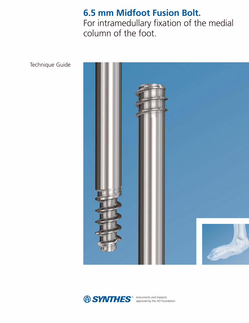
6.5 mm Midfoot Fusion Bolt. For intramedullary fixation of the medialcolumn of the foot.
Technique Guide

Introduction
Surgical Technique
Product Information
Table of Contents
6.5 mm Midfoot Fusion Bolt 2
AO Principles 4
Indications 5
Preoperative Planning 6
Preparation 7
Implantation 10
Supplemental Fixation 21
Postoperative Treatment 22
Implant Removal 22
Implants 23
Instruments 24
Set List 26
Image intensifier control
Synthes

6.5 mm Midfoot Fusion Bolt
The Midfoot Fusion Bolt is a solid intramedullary implant that can be used to fuse the medial metatarsocuneiform,naviculocuneiform, and talonavicular joints. Other uses of the Midfoot Fusion Bolt are fusion of the lateral column, calcaneocuboid, and 4th metatarsocuboid joint. The MidfootFusion Bolt is designed to achieve permanent fusion of thesejoints in patients suffering from gross instability such asCharcot neuroarthropathy with or without collapse of themidfoot. The Midfoot Fusion Bolt aids in the fusion of thejoints of the midfoot. Fusion of the midfoot can provide stabilization and alignment, enhancing the possibility of afunctional foot and increasing the likelihood of limb salvage.1, 2
The 6.5 mm Midfoot Fusion Bolt is:– A solid bolt, highly resistant to bending and shear loads– Headless, for complete countersinking– Able to achieve compression– Available in 50 mm–160 mm lengths– Available in stainless steel and titanium
2 Synthes 6.5 mm Midfoot Fusion Bolt Technique Guide
1. J.E. Johnson. "Operative Treatment of Neuropathic Arthropathy of the Foot andAnkle." Journal of Bone and Joint Surgery 80-A (1998): 1700–1709.
2. S.R. Simon, S.G. Tejwani, D.L. Wilson, T.J. Santner, N.L. Denniston. "Arthrodesisas an Early Alternative to Nonoperative Management of Charcot Arthropathy ofthe Diabetic Foot." Journal of Bone and Joint Surgery 82-A (2000): 939–950.
Features
Solid 6.5 mm diameter foradded strength in bendingand shear loads
Blunt tip minimizes soft tissuedamage if over-inserted
Head thread has same pitchas lead thread (2.7 mm)
Leading threads and shaft have the same diameter– Easy insertion with reduced risk of threads cutting
out of the bone
Cutting thread allows easyinsertion and countersinkinginto cortical bone
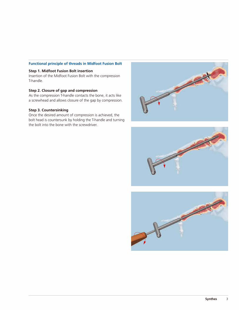
Functional principle of threads in Midfoot Fusion Bolt
Step 1. Midfoot Fusion Bolt insertionInsertion of the Midfoot Fusion Bolt with the compression T-handle.
Step 2. Closure of gap and compressionAs the compression T-handle contacts the bone, it acts like a screwhead and allows closure of the gap by compression.
Step 3. CountersinkingOnce the desired amount of compression is achieved, thebolt head is countersunk by holding the T-handle and turningthe bolt into the bone with the screwdriver.
Synthes 3

AO Principles
In 1958, the AO formulated four basic principles, which have become the guidelines for internal fixation:3
Anatomic reductionFracture reduction and fixation to restore anatomical relationships.
Stable fixationStability by fixation or splintage, as the personality of thefracture and the injury requires.
Preservation of blood supplyPreservation of the blood supply to soft tissue and bone bycareful handling. Use of surgical technique that minimizesdisruption of soft tissue and preserves vascular blood flowfor bone healing.
Early, active mobilizationEarly and safe mobilization of the part and patient. The implants, combined with AO technique, provide stable fracture fixation with minimal trauma to vascular supply.
4 Synthes 6.5 mm Midfoot Fusion Bolt Technique Guide
3. M.E. Müller, M. Allgöwer, R. Schneider, and R. Willenegger Manual of Internal Fixation, 3rd Edition. Berlin: Springer. 1991

Indications
The Synthes 6.5 mm Midfoot Fusion Bolt is indicated forfracture fixation, osteotomies, nonunions, and fusions of large bones in the foot and ankle.
Warning: The Midfoot Fusion Bolt is not to be used as astandalone implant and needs to be used with supplementalfixation, such as additional screws and plates across thearthrodesed joints.
Synthes 5

Preoperative Planning
Evaluation of x-rays
For good preoperative planning it is important to have the following x-rays:– Weight-bearing in three projections: Lateral, AP,
45º oblique AP
– AP of ankle
– Comparative x-rays of both sides
Preoperative examination and evaluation
Estimate the balance of the foot and the function of the vital tendons, especially the length of the Achilles tendonand gastrocnemius.
A gastrocnemius slide or percutaneous tendo-Achilleslengthening is needed as equinus contracture causes abnormally high stresses across the midfoot.
6 Synthes 6.5 mm Midfoot Fusion Bolt Technique Guide

Preparation
1Position patient
Place the patient in the supine position, with a roll under the affected hip to position the foot in neutral (toes straightup in a resting position).
2Perform gastrocnemius slide or percutaneous tendo-Achilles lengthening
A gastrocnemius slide or percutaneous tendo-Achilleslengthening is usually needed to relieve stresses across the midfoot.
Synthes 7

Preparation
8 Synthes 6.5 mm Midfoot Fusion Bolt Technique Guide
3Approach
Two or three incisions are usually needed to expose and prepare the joints to be fused.
Make a medial utility incision to expose and denude thetalonavicular, navicular cuneiform and tarsometatarsal joints.Take care to avoid the tibialis anterior tendon.
Make a dorsal straight incision over the first metatarsal phalangeal joint (MPJ) to expose the joint. This allows access for the drill bit and midfoot fusion bolt through thefirst metatarsal articular surface.
Note: At this stage of the procedure a subtalar fusion maybe performed, if necessary.
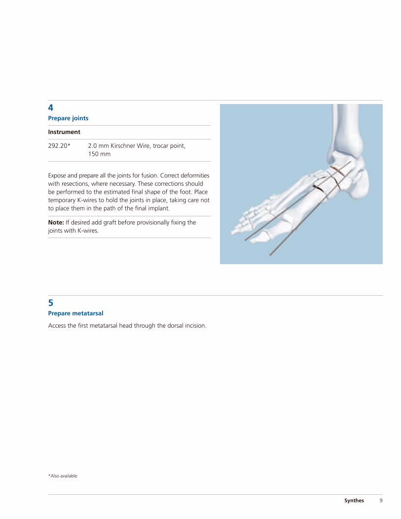
4Prepare joints
Instrument
292.20* 2.0 mm Kirschner Wire, trocar point, 150 mm
Expose and prepare all the joints for fusion. Correct deformitieswith resections, where necessary. These corrections shouldbe performed to the estimated final shape of the foot. Placetemporary K-wires to hold the joints in place, taking care notto place them in the path of the final implant.
Note: If desired add graft before provisionally fixing thejoints with K-wires.
5Prepare metatarsal
Access the first metatarsal head through the dorsal incision.
Synthes 9
*Also available
Implantation
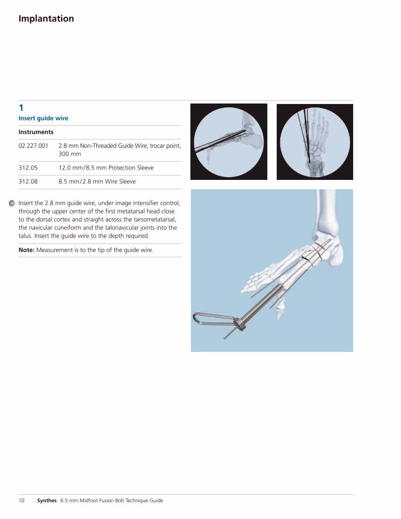
1Insert guide wire
Instruments
02.227.001 2.8 mm Non-Threaded Guide Wire, trocar point,300 mm
312.05 12.0 mm/8.5 mm Protection Sleeve
312.08 8.5 mm/2.8 mm Wire Sleeve
Insert the 2.8 mm guide wire, under image intensifier control,through the upper center of the first metatarsal head closeto the dorsal cortex and straight across the tarsometatarsal,the navicular cuneiform and the talonavicular joints into thetalus. Insert the guide wire to the depth required.
Note: Measurement is to the tip of the guide wire.
10 Synthes 6.5 mm Midfoot Fusion Bolt Technique Guide

Alternative: reverse technique
Instruments
02.227.001 2.8 mm Non-Threaded Guide Wire, trocar point,300 mm
312.05 12.0 mm/8.5 mm Protection Sleeve
312.08 8.5 mm/2.8 mm Wire Sleeve
Insert the 2.8 mm guide wire under image intensifier control,through the upper center of the first metatarsal head, closeto the dorsal cortex and straight across the tarsometatarsal,the navicular cuneiform and the talonavicular joints, into thetalus. Continue inserting the guide wire through the posteriorof the talus making sure it exits posterior, avoiding the subtalarjoint. From the back of the foot, readjust the guide wire position in the metatarsal head to allow measurement of the desired length of the midfoot fusion bolt.
Synthes 11

Implantation
2Measure for bolt length
Instrument
319.70 Cannulated Screw Measuring Device, for 6.5 mm and 7.3 mm Cannulated Screws
Place the measuring device over the guide wire and to thebone. Selected bolt length should reflect joint spaces, depthof countersink and desired position of the leading tip of the bolt.
Alternative: reverse technique
Instrument
319.70 Cannulated Screw Measuring Device for 6.5 mm and 7.3 mm Cannulated Screws
Place the measuring device over the guide wire and to thebone. Selected bolt length should reflect joint spaces, depthof countersink and desired position of the leading tip of the bolt.
12 Synthes 6.5 mm Midfoot Fusion Bolt Technique Guide

3Drill
Instruments
03.111.002 5.0 mm Three-Fluted Cannulated Drill Bit, quick coupling, 300 mm, 200 mm Calibration
357.047 6.5 mm Cannulated Drill Bit, quick coupling, 330 mm
When the reduction is complete, insert the 5.0 mm drill bitover the guide wire.
Under image intensification, drill to the final desired positionof the bolt.
Note: The length of the bolt can also be checked with thecalibrations on the 5.0 mm drill bit.
Verify under image intensification that the drill bit followsthe correct path and does not penetrate the end of the talus.
It is recommended to over-drill, especially in hard bone. Donot drill the entire length, as this will prevent purchase of the leading bolt threads.
Synthes 13
6.5 mm drill bit
5.0 mm drill bit

Implantation
3Drill continued
Alternative: reverse technique
Instruments
03.111.002 5.0 mm Three-Fluted Cannulated Drill Bit, quick coupling, 300 mm, 200 mm calibration
357.047 6.5 mm Cannulated Drill Bit, quick coupling, 330 mm
When the reduction is complete, insert the 5.0 mm drill bitover the guide wire.
Under image intensification, drill to the final desired positionof the bolt.
Note: The length of the bolt can also be checked with thecalibrations on the 5.0 mm drill bit.
Verify under image intensification that the drill bit followsthe correct path.
It is recommended to over-drill, especially in hard bone. Donot drill the entire length, as this will prevent purchase of the leading bolt threads.
14 Synthes 6.5 mm Midfoot Fusion Bolt Technique Guide
6.5 mm drill bit
5.0 mm drill bit
4Remove guide wire
Remove the guide wire to allow insertion of the solid midfootfusion bolt.
If stability is not maintained, add supplemental K-wires, ensuring that the wires are not in the path of the bolt.
5Select midfoot fusion bolt
Select the midfoot fusion bolt. Bolt length should reflect jointspaces, depth of countersink and desired position of the leadingtip of the bolt (Step 6). It is important that the midfoot fusionbolt is inserted well into the body of the talus.
Note: If there is excessive joint space, this should be consideredwhen choosing the bolt.
6Attach midfoot fusion bolt to T-handle
Instrument
03.111.001 T-Handle for Midfoot Fusion Bolt
Connect the midfoot fusion bolt to the T-handle and finger-tighten.
Synthes 15

Implantation
7Insert midfoot fusion bolt
Insert the midfoot fusion bolt into the metatarsal head. Use image intensification to visualize and control bolt insertion.
Place allograft or autograft in the prepared joints, if required.
Turn the T-handle until it reaches the cartilage of the joint.
16 Synthes 6.5 mm Midfoot Fusion Bolt Technique Guide
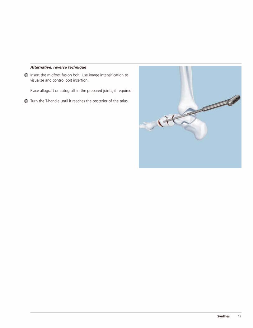
Alternative: reverse technique
Insert the midfoot fusion bolt. Use image intensification tovisualize and control bolt insertion.
Place allograft or autograft in the prepared joints, if required.
Turn the T-handle until it reaches the posterior of the talus.
Synthes 17

Implantation
8Compress joints
Under image intensification turn the T-handle until the desired compression is achieved.
Alternative: reverse technique
Under image intensification turn the T-handle until the desired compression is achieved.
18 Synthes 6.5 mm Midfoot Fusion Bolt Technique Guide
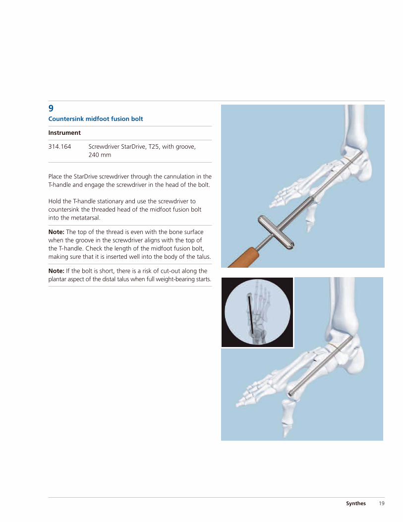
9Countersink midfoot fusion bolt
Instrument
314.164 Screwdriver StarDrive, T25, with groove, 240 mm
Place the StarDrive screwdriver through the cannulation in theT-handle and engage the screwdriver in the head of the bolt.
Hold the T-handle stationary and use the screwdriver tocountersink the threaded head of the midfoot fusion boltinto the metatarsal.
Note: The top of the thread is even with the bone surfacewhen the groove in the screwdriver aligns with the top ofthe T-handle. Check the length of the midfoot fusion bolt,making sure that it is inserted well into the body of the talus.
Note: If the bolt is short, there is a risk of cut-out along theplantar aspect of the distal talus when full weight-bearing starts.
Synthes 19

Implantation
9Countersink midfoot fusion bolt continued
Alternative: reverse technique
Instrument
314.164 Screwdriver StarDrive, T25, with groove, 240 mm
Place the StarDrive screwdriver through the cannulation in theT-handle and engage the screwdriver in the head of the bolt.
Hold the T-handle stationary and use the screwdriver tocountersink the threaded head of the midfoot fusion boltinto the posterior of the talus.
20 Synthes 6.5 mm Midfoot Fusion Bolt Technique Guide

Synthes 21
The Midfoot Fusion Bolt is to be used with supplemental fixation, such as additional screws and plates across thearthrodesed joints.
Synthes offers a wide selection of plates and screws whichcover a correspondingly extensive variety of indications. For this reason this technical guide does not cover specific indications or the selection of a plate type for specific clinicalsituations. For treatment of these subjects, please refer to“AO Principles of Fracture management” courses offered by the AO (www.aofoundation.org), and the correspondingprofessional literature.
Supplemental Fixation
22 Synthes 6.5 mm Midfoot Fusion Bolt Technique Guide
Postoperative Treatment and Implant Removal (optional)
Implant removal (optional)
Instruments
03.111.001 T-Handle for Midfoot Fusion Bolt
314.164 StarDrive Screwdriver, T25, with groove, 240 mm
Clear tissue ingrowth from the StarDrive recess at the end of the bolt. Screw the bolt out until the head is no longer engaged in the bone. Attach the T-handle, place the StarDrivescrewdriver through the cannulation in the T-handle, and engage the screwdriver in the head of the bolt. Holding theT-handle, turn the screwdriver counterclockwise to partiallyengage the bolt in the T-handle. Remove the screwdriver.While pulling gently, turn the T-handle counterclockwise.
Postoperative treatment
Immobilization in a well padded splint for the first two weeks.During this time a dependent position should be avoided.The dressing is removed at two weeks, the wound is evaluatedand gentle range of motion of the ankle and first metatar-sophalangeal joints is initiated. Full weight-bearing between10 to 12 weeks based on radiographic evidence of healing.

Synthes 23
Implants
6.5 mm Midfoot Fusion Bolts◊
Stainless Steel Titanium Length (mm)02.111.150 04.111.150 5002.111.155 04.111.155 5502.111.160 04.111.160 6002.111.165 04.111.165 6502.111.170 04.111.170 7002.111.175 04.111.175 7502.111.180 04.111.180 8002.111.185 04.111.185 8502.111.190 04.111.190 9002.111.195 04.111.195 9502.111.200 04.111.200 10002.111.205 04.111.205 10502.111.210 04.111.210 11002.111.215 04.111.215 11502.111.220 04.111.220 12002.111.225 04.111.225 12502.111.230 04.111.230 13002.111.235 04.111.235 13502.111.240 04.111.240 14002.111.245 04.111.245 14502.111.250 04.111.250 15002.111.255 04.111.255 15502.111.260 04.111.260 160
◊ Available nonsterile and sterile packed. Add “S” to catalog number for sterile product.

24 Synthes 6.5 mm Midfoot Fusion Bolt Technique Guide
Instruments
03.111.001 T-Handle for Midfoot Fusion Bolt
314.164 StarDrive Screwdriver, T25, 240 mm, with groove
03.111.002 5.0 mm Three-Fluted Cannulated Drill Bit, quick coupling, 300 mm, 200 mm calibration
02.227.001 2.8 mm Non-Threaded Guide Wire, trocar point, 300 mm
312.08 8.5 mm/2.8 mm Wire Sleeve
312.05 12.0 mm/8.5 mm Protection Sleeve

Synthes 25
319.70 Cannulated Screw Measuring Device, for 6.5 mm and 7.3 mm Cannulated Screws
357.047 6.5 mm Cannulated Drill Bit, quick coupling, 330 mm
338.49 Large Quick Coupling
Note: For additional information, please refer to package insert.
26 Synthes 6.5 mm Midfoot Fusion Bolt Technique Guide
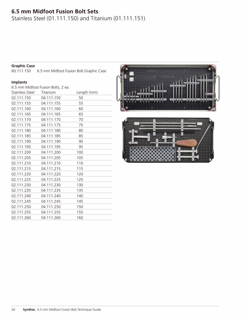
6.5 mm Midfoot Fusion Bolt SetsStainless Steel (01.111.150) and Titanium (01.111.151)
Graphic Case60.111.150 6.5 mm Midfoot Fusion Bolt Graphic Case
Implants6.5 mm Midfoot Fusion Bolts, 2 ea.Stainless Steel Titanium Length (mm)02.111.150 04.111.150 5002.111.155 04.111.155 5502.111.160 04.111.160 6002.111.165 04.111.165 6502.111.170 04.111.170 7002.111.175 04.111.175 7502.111.180 04.111.180 8002.111.185 04.111.185 8502.111.190 04.111.190 9002.111.195 04.111.195 9502.111.200 04.111.200 10002.111.205 04.111.205 10502.111.210 04.111.210 11002.111.215 04.111.215 11502.111.220 04.111.220 12002.111.225 04.111.225 12502.111.230 04.111.230 13002.111.235 04.111.235 13502.111.240 04.111.240 14002.111.245 04.111.245 14502.111.250 04.111.250 15002.111.255 04.111.255 15502.111.260 04.111.260 160
Synthes 27
Instruments02.227.001 2.8 mm Non-Threaded Guide Wire, trocar point,
300 mm, 8 ea.03.111.001 T-Handle for Midfoot Fusion Bolt03.111.002 5.0 mm Three-Fluted Cannulated Drill Bit,
quick coupling, 300 mm, 200 mm calibration312.05 12.0 mm/8.5 mm Protection Sleeve312.08 8.5 mm/2.8 mm Wire Sleeve314.164 StarDrive Screwdriver, T25, with groove,
240 mm319.70 Cannulated Screw Measuring Device, for
6.5 mm and 7.3 mm Cannulated Screws338.49 Large Quick Coupling357.047 6.5 mm Cannulated Drill Bit, quick coupling,
330 mm
Also Available60.111.152 Lid for 6.5 mm Midfoot Fusion Bolt
Graphic Case60.111.154 Instrument Tray for 6.5 mm Midfoot Fusion Bolt
Graphic Case292.20 2.0 mm Kirschner Wire, trocar point, 150 mm310.63 5.0 mm Cannulated Drill Bit, large quick
coupling, 300 mm

Synthes (USA)1302 Wrights Lane EastWest Chester, PA 19380Telephone: (610) 719-5000To order: (800) 523-0322Fax: (610) 251-9056
Synthes (Canada) Ltd.2566 Meadowpine BoulevardMississauga, Ontario L5N 6P9Telephone: (905) 567-0440To order: (800) 668-1119Fax: (905) 567-3185
© 2009 Synthes, Inc., or its affiliates. All rights reserved. Synthes is a trademark of Synthes, Inc., or its affiliates. Printed in U.S.A. 4/13 J8687-C
www.synthes.com


![Meta-analysis of plate fixation versus intramedullary fixation ......intramedullary fixation (IF), the common devices in clinics are Knowles pinning [14,15], elastic stable intramedullary](https://img.dokumen.tips/doc/110x75/60ec8dbb516bc21c1e0f6489/meta-analysis-of-plate-fixation-versus-intramedullary-fixation-intramedullary.jpg)