Embed Size (px)
Citation preview

Connection to Personal Computers
For non-backlight operation when the display is connected to a PC’s 9-pin serial port, all you need is a “straightthrough” 9-pin female DB9 to 9-pin female DB9 cable. This cable is available from Crystalfontz as part numberWR232Y01, or from Radio Shack as Cat No 26-152.
This is a view looking into the male DB9 connector (J1) on the Crystalfontz display:
Pin Number Crystalfontz Display Function Corresponding PC pin name1 Not Connected DCD (Data Carrier Detect)2 Not Connected Rx (Receive Data)3 Data In Tx (Transmit Data)4 Power A (9 volts to 15 volts) DTR (Data Terminal Ready)5 Ground (Vss) Signal Ground6 Connected to Power A if JPD is closed DSR (Data Set Ready)7 Power B (9 volts to 15 volts) RTS (Request To Send)8 Connected to Power B if JPC is closed CTS (Clear To Send)9 Not Connected RI (Ring Indicator)
Most RS-232 ports will be able to power the display through their DTR and RTS lines. Just have the softwaredrive these lines high—most software already will.
To power the backlight, you must connect a regulated 5v supply capable of sourcing 600mA (for the 634) or 300mA(for the 632) to the LED+ terminal of the LCD’s solder connector (J2). The supply’s ground should connect to theVSS terminal of the LCD’s solder connector (J2):
Pin Number Pin Name Crystalfontz Display Function1 Vss Ground (backlight and controller)2 Vdd Controller and LCD power (+5volt only)3 LED+ LED Backlight power (+5volt only)4 DATA_IN SPI or RS-232 data in (input)5 /SPI_CS SPI Chip Select (active low input)6 SPI_CLK SPI Clock (input)7 SPI_BUSY SPI Busy (output)
The easiest place on a PC to get 5v is from a disk drive power connector. The red wire is typically 5v, the blackwires are typically ground. Crystalfontz sells a cable that will connect from a spare power connector on your PCto the display’s LED backlight. The cable is part number WR232Y02. If you make your own cable, be sure andmeasure the output voltage before you connect the display. The colors are usually correct, but some computersmay have non-conventional colors.
WARNING: Do not use the yellow wire of the disk drive power cable. This wire is typically the 12 volt supply andwill ruin the display if it is connected instead of 5 volts.
7 1
STATIC SENSITIVE DEVICE -- USE PROPER ESD PROCEDURES
Connecting Your Crystalfontz Intelligent Serial Display v2.0

Connections in Embedded Systems
To connect the display in most embedded systems, you need only use the LCD’s solder connector (J2). Thisconnector has standard 0.1 inch spacing. Generally, you would connect a regulated 5v supply for the controller toVDD, Ground to VSS, and RS-232 data to DATA_IN. DATA_IN will accept full +10v to –10v swing RS-232 signalsand will also accept 0v to 5v “CMOS” or “TTL” levels (see JPE on v1.3 displays). If your RS-232 data is inverted, youcan close JPB.
If you would like, you can connect an unregulated 9 volt to 15 volt supply to Power A or Power B of the DB9 connec-tor instead of connecting a regulated +5 volt supply to VCC. Power A and Power B will only power the LCD itself, notthe backlight. Do not connect a supply greater than 5.25 volts to VDD or LED+. Damage to your LCD module willresult.
To use the backlight, connect a regulated 5v supply capable of sourcing 600mA (for the 634) or 300mA (for the 632)to the LED+ terminal. This may be the same supply that is used for VDD. The backlight brightness is controlled byPWM (Pulse Width Modulation). The PWM may cause noise on supplies that have high output impedance. If thisnoise causes problems in your application, you may want to connect a filter capacitor from VDD to VSS close to thedisplay, or operate the backlight at full brightness, which disables the PWM.
To use the SPI interface, close JPA. Please refer to the SPI timing diagrams in the data sheet. In some situations,the SPI interface can deliver data faster than the display can execute the commands. The host should check theSPI_BUSY line and wait for it to go low before sending the next SPI data byte.
Handshaking
The display can generally execute commands faster than the RS-232 serial interface can deliver them, so nohandshaking is necessary from the display’s point of view, the few exceptions involve accessing the EEPROM, andare listed in the command definitions of the data sheet.
Some host hardware or software may require the display to assert its DSR and/or CTS lines before it will send datato the display. In that case, JPC and/or JPD may be closed. Closing JPC will connect DSR to DTR through a 1Kresistor. Closing JPD will connect CTS to RTS through a 1K resistor.
Crystalfontz Intelligent Serial Display Jumper Settings
Your v2.0 display has seven jumpers. The jumpers are normally open. The jumpers may be closed by melting a ballof solder across their gap. You may re-open the jumpers by removing the solder (solder-wick works well for this). Thefollowing table describes the jumper’s operation.
Jumper State Function
JPA Open RS-232 interface selectedClosed SPI interface selected
JPB Open RS-232 data is normalClosed RS-232 data is inverted
JPC Open DSR is openClosed DTR is fed back on DSR
through 1K resistor
JPD Open CTS is openClosed RTS is fed back on CTS
through 1K resistor
Jumper State Function
JPE Open DATA_IN is RS-232(-10v to +10v swing)
Closed DATA_IN is 0v to 5v swing
JPK Open Show splash screenClosed Disable splash screen
JPL Open Frame Ground* is openClosed Grame Ground is connected to
Signal/Power supply GROUND
*Frame Ground is a trace connecting the mountingholes, the bezel and the shell of the DB-9 (J2)
Crystalfontz America, Incorporated
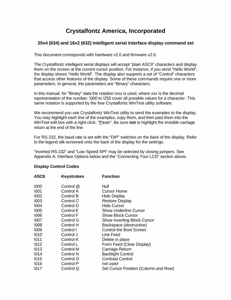
20x4 (634) and 16x2 (632) intelligent serial interface display command set This document corresponds with hardware v2.0 and firmware v2.0. The Crystalfontz intelligent serial displays will accept “plain ASCII” characters and display them on the screen at the current cursor position. For instance, if you send “Hello World”, the display shows “Hello World”. The display also supports a set of “Control” characters that access other features of the display. Some of these commands require one or more parameters. In general, the parameters are “Binary” characters. In this manual. for "Binary" data the notation \xxx is used, where xxx is the decimal representation of the number. \000 to \255 cover all possible values for a character. This same notation is supported by the free Crystalfontz WinTest utility software. We recommend you use Crystalfontz WinTest utility to send the examples to the display. You may highlight each line of the examples, copy them, and then past them into the WinTest edit box with a right-click, "Paste". Be sure not to highlight the invisible carriage return at the end of the line. For RS-232, the baud rate is set with the “DIP” switches on the back of the display. Refer to the legend silk-screened onto the back of the display for the settings. "Inverted RS-232" and "Low-Speed SPI" may be selected by closing jumpers. See Appendix A: Interface Options below and the “Connecting Your LCD” section above. Display Control Codes ASCII Keystrokes Function \000 Control @ Null \001 Control A Cursor Home \002 Control B Hide Display \003 Control C Restore Display \004 Control D Hide Cursor \005 Control E Show Underline Cursor \006 Control F Show Block Cursor \007 Control G Show Inverting Block Cursor \008 Control H Backspace (destructive) \009 Control I Control the Boot Screen \010 Control J Line Feed \011 Control K Delete in place \012 Control L Form Feed (Clear Display) \013 Control M Carriage Return \014 Control N Backlight Control \015 Control O Contrast Control \016 Control P not used \017 Control Q Set Cursor Position (Column and Row)

\018 Control R Horizontal Bar Graph \019 Control S Scroll ON \020 Control T Scroll OFF \021 Control U Set Scrolling Marquee Characters \022 Control V Enable Scrolling Marquee \023 Control W Wrap ON \024 Control X Wrap OFF \025 Control Y Set Custom Character Bitmap \026 Control Z Reboot \027 Escape Escape Sequence Prefix \028 Control Backslash Large Block Number (3x4 or 4x4) \029 Control Quote not used \030 Control Equal Send Data Directly to the LCD Controller \031 Control Minus Show Information Screen \128 Custom Character 0 \129 Custom Character 1 \130 Custom Character 2 \131 Custom Character 3 \132 Custom Character 4 \133 Custom Character 5 \134 Custom Character 6 \135 Custom Character 7 Explanation of Control Functions Cursor Home (\001 , Control A) Moves cursor to the top left character position. No data is changed. Identical to Control Q,0,0. Hide Display (\002 , Control B) Display is blanked, no data is changed. Restore Display (\003 , Control C) Restores blanked display; nothing else is changed. Hide Cursor (\004 , Control D) Cursor is not shown; nothing else is changed. Show Underline Cursor (\005 ; Control E) Shows a non-blinking underline cursor at the printing location. Show Block Cursor (\006 ; Control F) Shows a blinking block cursor at the printing location.

Show Inverting Block Cursor (\007 ; Control G) Shows a blinking block cursor at the printing location. This cursor inverts the character rather than replacing the character with a block. This cursor style is the default cursor at power-up. Backspace (\008 ; Control H) Moves the cursor back one space and erases the character in that space. Will wrap from the left-most column to the right-most column of the line above. Will wrap from the left-most column of the first row to the right-most column of the last row. Control the Boot Screen (\009 ; Control I) This command allows the current state of the display to be stored in the display’s EEPROM, recalling of the EEPROM contents to the display, and controlling the boot behavior. All features of the display are controlled: the characters displayed, the bitmaps of the user-definable characters, the backlight setting, the contrast setting, the cursor position, the cursor style, the “wrap” setting, the “scroll” setting, and even the scrolling marquee’s data and state. Since writing and reading the EEPROM takes quite a bit time, it is possible to overflow the display’s input buffer if data is continuously sent while the display is busy executing these commands. The display will still buffer data while these commands are being executed. However, the buffer is 64 bytes long and can be overflowed. You must take care to not overflow the input buffer while the EEPROM commands are executing. Send "Control I" followed by the command. \009 \000 Set boot to be backward Compatible with 1.3 (Execution time 5.1mS)
If JPK is open: Crystalfontz boot screen is displayed. The boot screen will clear automatically after about 5 seconds. If a character is received during that 5 seconds, the boot screen will be cleared immediately, then that character will be processed. This is also the v1.2 behavior.
If JPK is closed: No logo is shown.
\009 \001 Set boot to show Crystalfontz logo until a character arrives (Execution time 5.1mS)
The Crystalfontz boot screen is displayed. When a character is received, the boot screen will be cleared immediately, then that character will be processed.
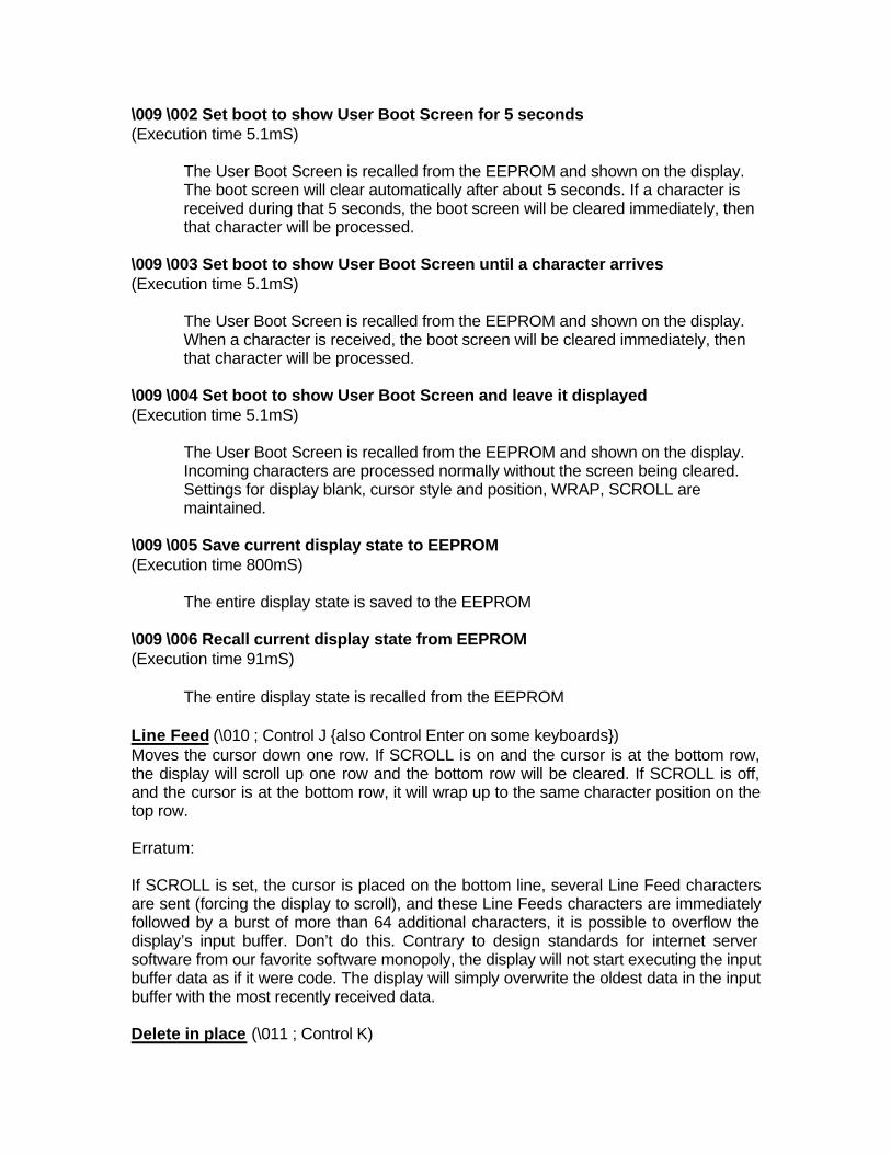
\009 \002 Set boot to show User Boot Screen for 5 seconds (Execution time 5.1mS)
The User Boot Screen is recalled from the EEPROM and shown on the display. The boot screen will clear automatically after about 5 seconds. If a character is received during that 5 seconds, the boot screen will be cleared immediately, then that character will be processed.
\009 \003 Set boot to show User Boot Screen until a character arrives (Execution time 5.1mS)
The User Boot Screen is recalled from the EEPROM and shown on the display. When a character is received, the boot screen will be cleared immediately, then that character will be processed.
\009 \004 Set boot to show User Boot Screen and leave it displayed (Execution time 5.1mS)
The User Boot Screen is recalled from the EEPROM and shown on the display. Incoming characters are processed normally without the screen being cleared. Settings for display blank, cursor style and position, WRAP, SCROLL are maintained.
\009 \005 Save current display state to EEPROM (Execution time 800mS)
The entire display state is saved to the EEPROM \009 \006 Recall current display state from EEPROM (Execution time 91mS)
The entire display state is recalled from the EEPROM Line Feed (\010 ; Control J {also Control Enter on some keyboards}) Moves the cursor down one row. If SCROLL is on and the cursor is at the bottom row, the display will scroll up one row and the bottom row will be cleared. If SCROLL is off, and the cursor is at the bottom row, it will wrap up to the same character position on the top row. Erratum: If SCROLL is set, the cursor is placed on the bottom line, several Line Feed characters are sent (forcing the display to scroll), and these Line Feeds characters are immediately followed by a burst of more than 64 additional characters, it is possible to overflow the display’s input buffer. Don’t do this. Contrary to design standards for internet server software from our favorite software monopoly, the display will not start executing the input buffer data as if it were code. The display will simply overwrite the oldest data in the input buffer with the most recently received data. Delete in place (\011 ; Control K)

Deletes the character at the current cursor position. Cursor is not moved. Form Feed (\012 ; Control L) Clears the display and returns cursor to Home position (upper left). All data is erased. Carriage Return (\013 ; Control M) Moves cursor to the left-most column of the current row. Backlight Control (\014 ; Control N) Send "Control-N", followed by a byte from 0-100 for the backlight brightness. 0=OFF, 100=ON, intermediate values will vary the brightness. There are a total of 25 possible brightness levels. Examples: \014\000 \014\050 \014\100 Contrast Control (\015 ; Control O) Send "Control O", followed by a byte from 0-100 for the contrast setting of the displayed characters. 0 = very light, 100 = very dark, 50 is typical. There are a total of 25 possible contrast levels. Examples: \015\050 \015\060 \015\070 Set Cursor Position (Column and Row) (\017 ; Control Q) Send "Control Q" followed by one byte for the column (0-19 for a 20x4 display, or 0-15 for a 16x2 display), and a second byte for the row (0-3 for a 4x20 or 0-1 for a 2x16). The upper-left position is 0,0. The lower-right position is 15,1 for a 16x2, and 19,3 for a 20x4. Here is an example for moving the cursor to column 11 of the second line: \017\010\001 Horizontal Bar Graph (\018 ; Control R) Send "Control R" followed by the following bytes: graph_index style start_column end_column length row graph_index determines which special characters are used:

graph_index custom characters used \000 0,1 \001 2,3 \002 4,5 \003 6,7 style is the bit pattern to use in drawing the graph: \255 (11111111b) is a thick bar \000 (00000000b) will not be visible (all pixels are off) \085 (01010101b) is a striped bar \060 (00111100b) is a medium width bar, centered \015 (00001111b) is a medium width bar, low in the row \240 (11110000b) is a medium width bar, high in the row any value is valid between \000 and \255, the msb is at the top of the row, the lsb is at the bottom of the row. start_column and end_column are the character X coordinates of the graph area. Each must be between \000 and \019 for the 20x4 or between \000 and \015 for the 16x2. start_column must be less than or equal to end_column. length is the length in pixels of the graph. Positive values will graph from the left edge of start_column, negative values will graph from the right edge of end_column. There are six pixels per character, so the maximum value of length for a 20x4 display is 20*6=\120. For a 16x2, the maximum value is 16*6=\096. row is the character Y coordinate. \000-\003 is valid for the 20x4, \000-\001 is valid for the 16x2. Examples: \018\000\255\000\014\010\001 \018\000\015\000\014\236\001 Notes: The entire graph area is completely re-written by each graph command, so there is no need to clear the area between successive updates of the same graph. If a length of \000 is written the entire graph area is cleared to spaces. Negative values can be calculated as 256-value. For instance if you want a graph to extend 20 pixels towards the left, from the rightmost column of the graph area, send 236 (256-20 = 236). No additional graph "setup" command is needed. The graphs use some of the custom characters, and so may goof up the display if there are user-defined custom characters or large numbers shown. Scroll ON (\019 ; Control S) Turns Scroll feature ON. Then a Line Feed (Control J) command from the bottom row will scroll the display up by one row, independent of Wrap. If Wrap is also on, a wrap

occurring on the bottom row will cause the display to scroll up one row. Scroll is on at power up. Scroll OFF (\020 ; Control T) Turns Scroll feature OFF. Then a Line Feed (Control J) command from the bottom row will move the cursor to the top row of the same column, independent of Wrap. If Wrap is also on, a wrap occurring on the bottom row will also wrap vertically to the top row. Scroll is on at power up. Set Scrolling Marquee Characters (\021 ; Control U) Send "Control U" followed by the following bytes: index character index determines which of the 20 scrolling marquee characters gets set, \000 to \019 are valid character is the value that this position in the scrolling marquee wil be set to Examples: This will set the first 12 characters to "Crystalfontz", put another message on the display, and enable the scrolling marquee. The second line of this example ends in a space: \004\022\255\001\005\012\017\000\001Scrolling Marquee \021\000C\021\001r\021\002y\021\003s\021\004t\021 \005a\021\006l\021\007f\021\008o\021\009n\021\010t \021\011z\021\012 \021\013 \021\014 \021\015 \021 \016 \021\017 \021\018 \021\019 \022\001\001\016 Notes: There is a section of memory that holds 20 hidden characters. These 20 characters, along with the contents of one line of the display can be rotated pixel by pixel across the display in a circular fashion. Use this command multiple times to set the 20 hidden characters. Use the normal display functions to set the other characters in the line you want to rotate, and then enable rotation with Enable Scrolling Marquee command. The hidden characters are set to blanks at power-up, or loaded from the User Boot Screen. You will probably want to disable the scrolling marquee movement while you are setting the scrolling marquee characters or modifying characters on the rotating line. You will probably also want to move the cursor off the line or hide it. WinTest, available at http://www.crystalfontz.com easily allows setting up the scrolling marquee and adjusting the parameters, so you can find a setting that is to your taste in a minimum amount of time. Erratum:
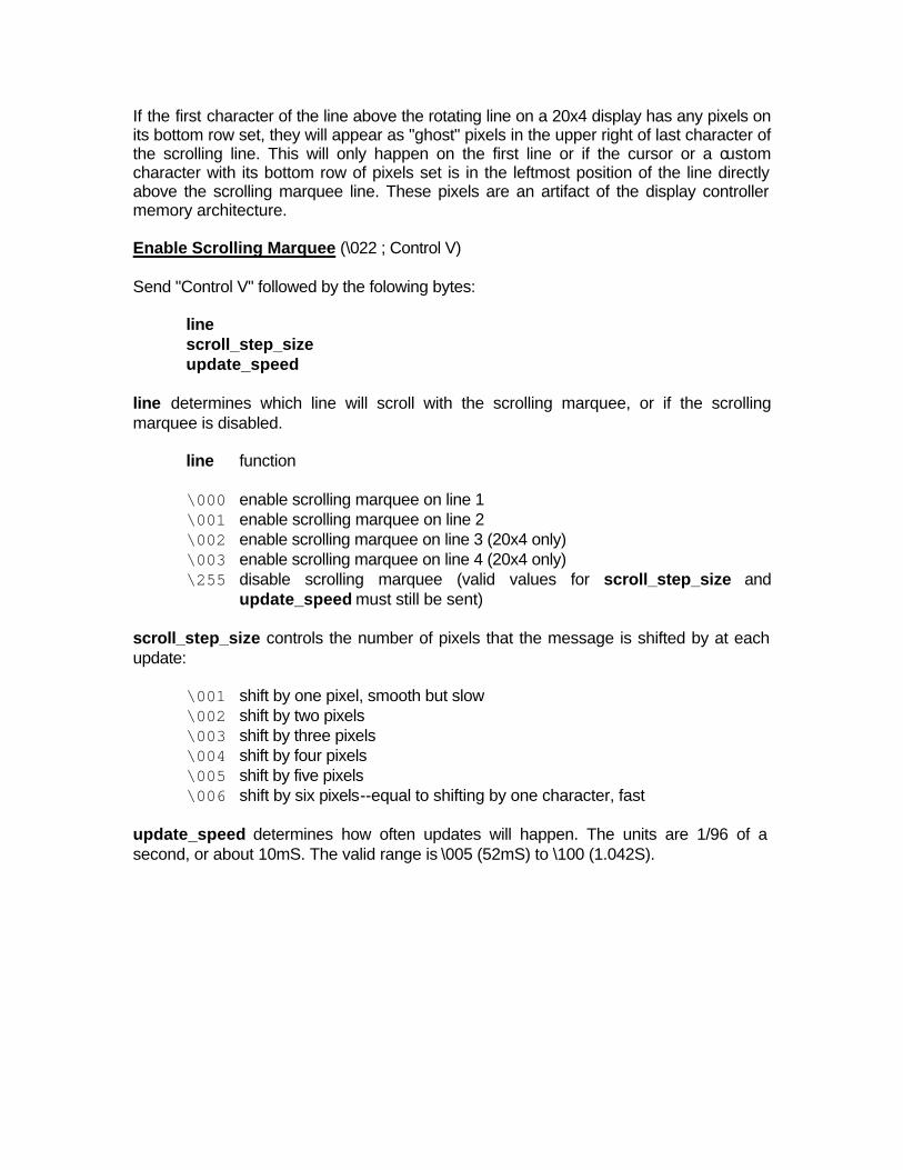
If the first character of the line above the rotating line on a 20x4 display has any pixels on its bottom row set, they will appear as "ghost" pixels in the upper right of last character of the scrolling line. This will only happen on the first line or if the cursor or a custom character with its bottom row of pixels set is in the leftmost position of the line directly above the scrolling marquee line. These pixels are an artifact of the display controller memory architecture. Enable Scrolling Marquee (\022 ; Control V) Send "Control V" followed by the folowing bytes: line scroll_step_size update_speed line determines which line will scroll with the scrolling marquee, or if the scrolling marquee is disabled. line function \000 enable scrolling marquee on line 1 \001 enable scrolling marquee on line 2 \002 enable scrolling marquee on line 3 (20x4 only) \003 enable scrolling marquee on line 4 (20x4 only)
\255 disable scrolling marquee (valid values for scroll_step_size and update_speed must still be sent)
scroll_step_size controls the number of pixels that the message is shifted by at each update: \001 shift by one pixel, smooth but slow \002 shift by two pixels \003 shift by three pixels \004 shift by four pixels \005 shift by five pixels \006 shift by six pixels--equal to shifting by one character, fast update_speed determines how often updates will happen. The units are 1/96 of a second, or about 10mS. The valid range is \005 (52mS) to \100 (1.042S).

Notes: Since the liquid crystal fluid in the display takes some time to react, the minimum usable value is about 16 or 167mS. The command supports a large range of speed to accomodate future displays and user preference. The following equations will allow you to determine the speed at which the message scrolls: Update Frequency = update_speed/96 Hz Update Period = 96/update_speed Seconds New Character Frequency = (scroll_step_size * update_speed)/(96*6) Hz New Character Period = (96*6)/(scroll_step_size * update_speed) Seconds 16x2 Message Repeat Period = (36*96*6)/(scroll_step_size * update_speed) Seconds 20x4 Message Repeat Period = (40*96*6)/(scroll_step_size * update_speed) Seconds See the example in Set Scrolling Marquee Characters above. WinTest, available at http://www.crystalfontz.com easily allows setting up the scrolling marquee and adjusting the parameters, so you can find a setting that is to your taste in a minimum amount of time. Wrap ON (\023 ; Control W) Turns Wrap feature ON. Then, a printable character received when the cursor is at the right-most column will cause the cursor to move down one row, to the left-most column. If the cursor is already at the right-most column of the bottom row, it will wrap to the top row if Scroll is OFF, or the display will scroll up one row if Scroll is ON. Wrap OFF (\024 ; Control X) Turns Wrap feature OFF. Then, a printable character received when the cursor is at the right-most column will cause the cursor to disappear (as it will be off the right edge of the screen) and any subsequent characters will be ignored until some other command moves the cursor back onto the display. This function is independent of Scroll. Set Custom Character Bitmap (\025 ; Control Y) The custom characters are mapped at \128 through \135 corresponding to character 0 to character 7. Send "Control Y" followed by the following bytes: character data0 data1 data2 data3 data4 data5 data6 data7
character determines which of the eight custom characters is modified. 0-7 is valid. The custom characters are displayed by sending \128 to \135: To display custom character 0, send \128 To display custom character 1, send \129 To display custom character 2, send \130 To display custom character 3, send \131 To display custom character 4, send \132 To display custom character 5, send \133 To display custom character 6, send \134 To display custom character 7, send \135 data0-data7 are the bitmap information for this character. Any value is valid between 0 and 63, the msb is at the left of the character cell of the row, and the lsb is at the right of the character cell. data0 is at the top of the cell, data7 is at the bottom of the cell. Notes: The large digits use all of the custom characters, so if you modify the custom characters when large digits are displayed, the display will probably become corrupted. The bar graphs also use some of the custom characters. Example: \012\001\128\129\130\131\017\000\001\132\133\134\135 \025\000\000\000\001\003\000\031\031\031 \025\001\028\054\032\001\003\051\051\051 \025\002\014\027\049\032\032\047\032\047 \025\003\000\000\032\048\000\062\000\062 \025\004\031\031\031\000\003\001\000\000 \025\005\051\051\051\003\001\032\054\028 \025\006\047\032\047\032\032\049\027\014 \025\007\062\000\062\000\048\032\000\000 Reboot (\026 ; Control Z) The firmware in your Crystalfontz Intelligent Display is very stable and robust, and it is not likely that you will ever need a "reboot" command. In fact, if the firmware actually did crash, the command processor would likely be inoperable and unable to detect the reboot command anyway. However, there may be certain situations where it is nice to have a command that will return the display to a known state. Perhaps the baud rate on the host was set to an incorrect speed. Then the data is interpreted as all sorts of meaningless garbage, which the display firmware tries to interpret. Some data may set the contrast to an unusable value, some data may program the LCD controller to an indeterminate state. Or perhaps you just always want the display to wake up in a given state when your program starts, without going through all the commands that affect the way the display interprets commands (like the state of Scroll or Wrap, for instance). Send one "Control Z" followed by another "Control Z" to reboot the display. If you are not sure of the display state, it may be necessary to send up to 9 characters to satisfy the parameters of some previous command. As an example, say the Set Custom

Character Bitmap command has just been received by the display when your PC's popular but unstable operating system crashes. The display will interpret the next 9 bytes as the parameters to the command, then wait for more commands. So if you are not sure what the status of the display is, send 9 blanks (\032) followed by two Control Zs (\026). If the display in your system is powered by the serial port's RTS and DTR lines, the display can be rebooted by dropping those lines momentarily (say 500mS) and then bringing them high again. Escape Sequences There are 4 Escape sequences currently supported. These correspond to the escape sequences that are sent for the four arrows keys in HyperTerminal with an ANSI terminal selected (and also WinTest). These sequences move the cursor only, and do not wrap. ESC [ A (equivalent to \027\091\065) UP arrow ESC [ B (equivalent to \027\091\066) DOWN arrow ESC [ C (equivalent to \027\091\067) RIGHT arrow ESC [ D (equivalent to \027\091\068) LEFT arrow Large Block Number (\028 ; Control Backslash) This command is only valid on the 20x4. On the 16x2 it is parsed and then discarded. Send "Control Backslash" followed by the following bytes: style column number style determines if a 3x4 or a 4x4 large number is displayed: style function \000 3x4 large number \001 4x4 large number \002-\255 invalid column is the starting column of the number. \000-\017 are valid for a style of \000 (3x4), \000-\016 are valid for a style of \001 (4x4). number is the number to display. \048 to \057 ('0' to '9') are valid.

Notes: The large numbers use all the custom characters. There will be some corruption if they are used at the same time as the graphs or user defined custom characters. There is no large number initialization command needed. Examples: \004\012\028\000\0010\028\000\0051\028\000\0092\028\000\0133\028\000\0174 \004\012\028\000\0005\028\000\0046\028\000\0087\028\000\0128\028\000\0169 \004\012\028\001\0000\028\001\0051\028\001\0102\028\001\0153 \004\012\028\001\0006\028\001\0057\028\001\0108\028\001\0159 Send Data Directly to the LCD Controller (\030 ; Control Equal) Send "Control Equal" followed by the folowing bytes: location data location is the destination register on the LCD controller: location register \000 Control Register, (RS=0, RE=0) \001 Data Memory, (RS=1, RE=x) \002 Control Register, (RS=0, RE=1) data is the data to write to the controller Notes: This command executes a low level write directly to the controller. Use this command at your own risk. Control Z, Control Z will reboot the display and recover from most mistakes. Example: \030\002\031\030\002\130 Show Information Screen (\031 ; Control Minus) This command will show the baud rate, version and model number.

Appendix A: Interface Options "Inverted RS-232" or "Low-Speed SPI" may be selected by closing jumpers. "Inverted RS-232" is useful when the display is used with an embedded micro controller’s built-in UART. These UARTs typically output a logic level (0-5v) inverted version of the RS-232 waveform, ready to be passed into an RS-232 driver. By setting the display to accept inverted RS-232 data, you can connect this logic level signal directly to the display and avoid having the RS-232 driver. The display will show a lowercase "i" before the baud rate on the information screen if the jumper is closed ("i9600bd"). "Low-Speed SPI" is intended to be used with low-end embedded microprocessors that lack a hardware UART. The reason that it is "Low-Speed" is that the SPI is done in firmware on the display. On the host microprocessor, any three general-purpose output ports and a small "send byte" routine can be used to control the display. If the host microprocessor has a hardware SPI port, that can be used, provided that the port's speed can be set to satisfy the timing constraints. A software state-machine and a timer interrupt could also be used, this would reduce the microprocessor's load while still satisfying the timing requirements. Another useful feature of SPI is that additional displays can be controlled with only one additional output port (SPI_CS) per display. All the other lines (/SPI_CLK and SPI_DATA) are common. The display will show "SPI" instead of the baud rate on the information screen. The Crystalfontz intelligent serial display has a 64-character input buffer. For the RS-232 interface, it is nearly impossible to overflow this buffer since the display can process commands more quickly than the 19200-baud RS-232 interface can deliver them, so normally no flow control is needed. The exceptions are the routines that access the EEPROM (the \009 series) and a very rare combination of commands that tale a long time to execute, followed by a burst of characters that is larger than the input buffer. If the your processor can deliver data through the Low-Speed SPI interface at a rate faster than 1000 bytes/second, then the processor should make sure the SPI_BUSY line is low before sending a new command. The SPI_BUSY line will be set high by the display when there are 32 or more characters in the display's input buffer, and returned low when there are less than 32 characters.

Appendix B: Character Generator ROM (CGROM) The CGROM defines what characters are shown by the display for a given code received through the serial port. The v2.0 series of the Crystalfontz Intelligent Serial Displays have an enhanced CGROM that includes many useful special characters (numeric superscripts, icons, mathematical symbols, some fractions, a great variety of arrows, many currency symbols . . .). Most of the characters can be accessed by sending the appropriate ASCII code to the display. For instance, the letter ‘A’ can be shown by sending an ‘A’ (which is the same as a “decimal 65”, or a “hex 0x41”) to the display. Some characters do not have an obvious match, For instance, the code to display a superscript ‘9’ is a “decimal 137” or “hex 0x89”. The relationship between the codes and the characters are shown on in the “CGROM” table on the next page. To find the code for a given character add the two numbers that are shown in bold for its row and column. As an example, the superscript ‘9’ is in the column labeled “128d” and in the row labeled “9d”. So you would add 128 + 9 to get 137. When you send a byte with the value of 137 to the display, then a superscript 9 will be shown at the current cursor position. In the 1.x series of these displays, the CGROM table had several columns that did not have any characters assigned to the codes. The commands to control the display were mapped to some of those unused codes. These codes are shown in red in the table. Specifically, the first 32 codes (0 to 31) are reserved for the display’s special functions (cursor positioning, contrast control, bar graphs . . .), and the codes from 128 to 135 are used to access the “custom characters”. So to access the characters shown in red, it is necessary to send some data directly to the LCD controller. Command \030, “Send Data Directly to the LCD Controller” allows any character in the CGROM to be displayed. If you want to display an arrow that points to the upper left, you would look at the table and note that it is in column “16d”, and in row “6d”, so its code is 22. The following sequence would then display the arrow that points to the upper left: \030\001\022 This sequence of three bytes must be used to display any of the characters shown in red in the table. It can also be used to access any character in the table.


Appendix C: Crystalfontz America Contact Information Crystalfontz America, Incorporated 15611 East Washington Road Valleyford, WA 99036-9747 Phone: (509) 291-3514 Fax: (509) 291-3345 Technical support e-mail: [email protected] Sales e-mail: [email protected] Web Site: http://www.crystalfontz.com