Embed Size (px)
Citation preview
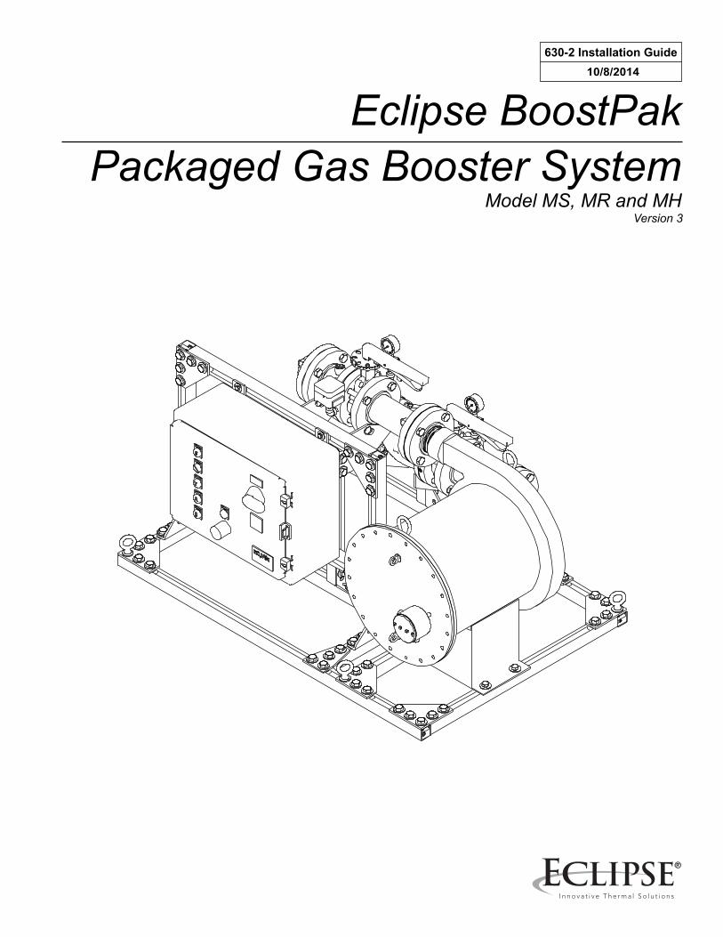
Eclipse BoostPakPackaged Gas Booster System
Model MS, MR and MH
630-2 Installation Guide10/8/2014
Version 3
2
CopyrightCopyright 2007 by Eclipse, inc. All rights reservedworldwide. This publication is protected by federalregulation and shall not be copied, distributed,transmitted, transcribed or translated into any human orcomputer language, in any form or by any means, to anythird parties, without the express written consent ofEclipse, inc.
Disclaimer NoticeIn accordance with the manufacturer’s policy of continualproduct improvement, the product presented in thisbrochure is subject to change without notice or obligation.
The material in this manual is believed adequate for theintended use of the product. If the product is used forpurposes other than those specified herein, confirmationof validity and suitability must be obtained. Eclipsewarrants that the product itself does not infringe upon anyUnited States patents. No further warranty is expressed orimplied.
Liability & WarrantyWe have made every effort to make this manual asaccurate and complete as possible. Should you find errorsor omissions, please bring them to our attention so that wemay correct them. In this way we hope to improve ourproduct documentation for the benefit of our customers.Please send your corrections and comments to ourTechnical Documentation Specialist.
It must be understood that Eclipse’s liability for its product,whether due to breach of warranty, negligence, strictliability, or otherwise is limited to the furnishing ofreplacement parts and Eclipse will not be liable for anyother injury, loss, damage or expenses, whether direct orconsequential, including but not limited to loss of use,
income, or damage to material arising in connection withthe sale, installation, use of, inability to use, or the repairor replacement of Eclipse’s products.
Any operation expressly prohibited in this manual, anyadjustment, or assembly procedures not recommended or authorized in these instructions shall void the warranty.
Document ConventionsThere are several special symbols in this document. Youmust know their meaning and importance.
The explanation of these symbols follows below. Pleaseread it thoroughly.
How To Get HelpIf you need help, contact your local Eclipserepresentative. You can also contact Eclipse at:
1665 Elmwood Rd.Rockford, Illinois 61103 U.S.A.Phone: 815-877-3031Fax: 815-877-3336http://www.eclipsenet.com
Please have the information on the product label availablewhen contacting the factory so we may better serve you.
Product NameItem #S/NDD MMM YYYY
www.eclipsenet.com
This is the safety alert symbol. It is used to alert you to potential personalinjurt hazards. Obey all safety messages that follow this symbol to avoidpossible injury or death.
Indicates a hazardous situation which, if not avoided, will result in deathor serious injury.
Indicates a hazardous situation which, if not avoided, could result indeath or serious injury.
Indicates a hazardous situation which, if not avoided, could result inminor or moderate injury.
Is used to address practices not related to personal injury.
Indicates an important part of text. Read thoroughly.NOTENOTICE
CAUTION
WARNING
3Eclipse Packaged Gas BoostPak, V3, Installation Guide 630-2, 10/8/2014
Table of Contents1 Introduction............................................................................................................................ 4
Product Description .............................................................................................................. 4Audience .............................................................................................................................. 4Purpose................................................................................................................................ 4Related Documents.............................................................................................................. 4
2 Safety...................................................................................................................................... 5Safety Warnings ................................................................................................................... 5Capabilities........................................................................................................................... 5Operator Training ................................................................................................................. 5Replacement Parts............................................................................................................... 5
3 Installation.............................................................................................................................. 6Introduction........................................................................................................................... 6Handling & Storage .............................................................................................................. 6Checklist Before Installation ................................................................................................. 6Mechanical Installation ......................................................................................................... 6Piping Installation ................................................................................................................. 6Electrical Installation............................................................................................................. 7Checklist After Installation .................................................................................................... 8
4 Commissioning...................................................................................................................... 9Introduction........................................................................................................................... 9Applying Power .................................................................................................................... 9Motor Rotation Check........................................................................................................... 9Applying Gas Supply ............................................................................................................ 9Operational Tests ................................................................................................................. 9Verifying Settings ................................................................................................................. 9Commissioning Record for Models MS/MR/MH................................................................... 10MH Models Temperature Control Settings ........................................................................... 11MH Models Rotary Actuator Settings ................................................................................... 11
5 Operation................................................................................................................................ 12Introduction........................................................................................................................... 12Heat Exchanger Loop Operation.......................................................................................... 12Alarm Silence ....................................................................................................................... 12Shutdown ............................................................................................................................. 12
6 Maintenance & Troubleshooting.......................................................................................... 13Monthly Checklist ................................................................................................................. 13Yearly Checklist.................................................................................................................... 13Alarm Conditions .................................................................................................................. 13BoostPak Models MS/MR/MH Wiring Diagram.................................................................... 15Boost Motor Voltage............................................................................................................. 17Heat Exchanger Motor Voltage ............................................................................................ 17Panel Layout and Enclosure ................................................................................................ 18BoostPak Model MS/MR/MH Piping Schematics ................................................................. 19
Appendix ................................................................................................................................... iConversion Factors .............................................................................................................. iKey to System Drawings ...................................................................................................... ii
4 Eclipse Packaged Gas BoostPak, V3, Installation Guide 630-2, 10/8/2014
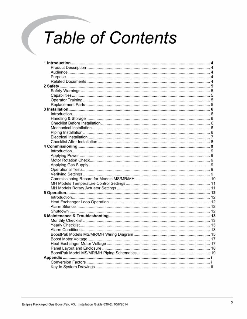
IntroductionProduct DescriptionThe Eclipse BoostPak is designed for installations whenthe gas pressure to a building is inadequate to operate theappliances. It provides a reliable cost-effective packagedsolution for pumping low natural gas supply pressures upto meet the requirements of high performance combustionequipment. The discharge pressure is the total of thebooster added pressure plus the incoming gas pressure.
The BoostPak is a completely integrated skid mountedpackage. It is factory assembled, wired, tested, and readyfor field power and gas connections. The system includesbut is not limited to a hermetically sealed centrifugal typegas booster blower, check valve, gas pressure switch,isolating valves, inlet and outlet piping and flangeconnectors, pressure gauges, and control system allmounted, assembled, wired, and tested. All essentialcomponents for automatic operation are enclosed in anindustrial control panel designed to meet local andnational electrical codes.
Various standard options may be selected to configure acomplete model number. The options determine thecontrol modes, pressure boost, flow, and environmentalconditions.
Figure 1.1. Eclipse BoostPak
AudienceThis manual has been written for personnel alreadyfamiliar with all aspects of a gas booster system and it’sadd-on components.
These aspects are:
• Installation• Use• Maintenance• Safety
The audience is expected to be qualified and haveexperience with this type of equipment and its workingenvironment.
PurposeThe purpose of this manual is to make sure that you carryout the installation of a safe, effective and trouble-freesystem.
BoostPak DocumentsInstallation Guide No. 630-2
• This documentDatasheet No. 630-2
• Available for BoostPak model MS• Provides assembly drawing numbers• Required to complete installation
Datasheet No. 630-3• Available for BoostPak model MR• Provides assembly drawing numbers• Required to complete installation
Datasheet No. 630-4• Available for BoostPak model MH• Provides assembly drawing numbers• Required to complete installation
Related Documents• EFE 825 (Combustion Engineering Guide)• Eclipse Bulletins and Information Guides: 620, 710,
780, 904 (MH only), 925 (MH only), 940
1
3Eclipse Packaged Gas BoostPak, V3, Installation Guide 630-1, 6/22/2010
SafetyImportant notices for safe operation of the BoostPaksystem will be found in this section. To avoid personalinjury, damage to property or the facility, the followingwarnings must be observed. Read this entire manualbefore attempting to start the system. If any part of theinformation in this manual is not understood, contactEclipse before continuing.
Safety Warnings
■ The BoostPak packaged gas booster systems,covered by this guide are designed to increase gaspressure to a gas utilization appliance. All fuelhandling devices are capable of producing firesand explosions if improperly applied, installed,adjusted, controlled or maintained.
■ Do not bypass any safety feature; fire or explosioncould result.
■ Never try to operate a BoostPak if it shows signsof damage or malfunction.
■ This manual provides information in the use of theBoostPak for its specific design purpose. Do notdeviate from any instructions or application limitsdescribed herein without written advice fromEclipse.
CapabilitiesOnly qualified personnel, with good mechanical aptitudeand experience with combustion equipment, shouldadjust, maintain or troubleshoot any mechanical orelectrical part of this system.
Operator TrainingThe best safety precaution is an alert and trainedoperator. Train new operators thoroughly and have themdemonstrate an adequate understanding of theequipment and its operation. A regular retraining scheduleshould be administered to ensure operators maintain ahigh degree of proficiency.
Replacement PartsOrder replacement parts from Eclipse only. Any customersupplied valves or switches should carry UL, FM, CSA,CGA and/or CE approvals where applicable.
DANGER
NOTICE
2
6 Eclipse Packaged Gas BoostPak, V3, Installation Guide 630-2, 10/8/2014
InstallationIntroductionIn this chapter you will find information and instructionsneeded to install the BoostPak and system components.The system drawings are shipped with the BoostPak.Refer to the data sheet for the drawing number andcontact Eclipse for a replacement.
■ All installation work must be carried out incompliance with current legislated standards.
Handling & StorageHandling
• Make sure the area is clean.• Inspect the system, ensure that all components are
clean and free from damage.• Use appropriate support and handling equipment
when lifting the BoostPak.• Protect the components from weather, damage, dirt
and moisture.• Protect the system and components from excessive
temperatures and humidity.
Storage• Make sure the components are clean and free of
damage.• Store the components in a cool, clean, dry room.• After making sure everything is present and in good
condition, keep the components in original packages as long as possible.
Checklist Before InstallationPlacementThe Eclipse BoostPak is completely factory piped, wiredwith controls, tested and ready for field connections. Thesystem should be installed in an accessible ventilatedlocation on a level concrete floor or substantial mountingpad. Place the BoostPak to avoid excessive numbers ofbends and fittings in the interconnecting piping.
AccessThe BoostPak location must allow easy accessibility forinspection and maintenance. Provide adequate space all
around the BoostPak in order to facilitate servicing andfield replacement of components. Avoid obstructing theopen access to the control panel.
NOTE: There should be no less than 36" of clearancefrom the front of the control panel door and the swing ofthe door should not be obstructed from opening 120°. Iflocal codes are different than these requirements, thosecodes should be adhered to during installation.
EnvironmentBe sure the operating environment matches the originaloperating specifications. Check the following items:
• Voltage, frequency, and stability of electrical power• Ambient temperature and humidity• Area classification (non-hazardous or hazardous)• Exposure to sunlight, water, ice, wind, and vibration
Mechanical InstallationLift PointsUse lifting lugs on mounting base for all lifting. Do not usepiping or supports as lift points unless designated bymanufacturer labeling.
MountingBolt the unit base securely using the mounting holesprovided in the BoostPak base.
Piping InstallationGas PipingAll gas piping must be done in accordance with thenational fuel gas code, local utility company and municipalagency requirements. Protect and prevent contaminationof the piping during installation.
NOTE: If it is necessary to redirect piping, make sure alldevices are properly oriented with respect to flow directionand vertical (gravity) orientations.
NOTE: Avoid severe size reductions in pipe connections,unnecessary fittings, and excessive bends that maycause additional flow restriction and pressure loss.Elbows within 5 pipe diameters may reduce pressure andcapacity below operating requirements.
WARNING
3
7Eclipse Packaged Gas BoostPak, V3, Installation Guide 630-2, 10/8/2014
Piping SupportUse brackets or hangers to support the gas piping. If youhave questions, consult your local gas company.
Initial Fitting• Remove any shipping materials and inspect for
foreign objects in the piping.• Connect inlet gas piping from the utility supply to the
inlet flange as indicated by directional arrows and system drawings.
• Connect the gas pipe requiring the boosted gas pressure feeding your appliance to the discharge gas pipe outlet flange, also indicated by label and system drawing.
Vent PipingThe model MS, MR and MH BoostPaks do not requirevent piping. Vent piping may be required for componentsadded to the system. Check the individual product datasheets for specific manufacturer’s recommendations.
Inlet Low Gas Manual Reset Pressure SwitchThis switch may come already mounted and wired on theBoostPak, or it may be supplied as a kit to be remotelymounted. Install loose inlet gas low pressure switch kit inlocation determined by the utility company. Normally it islocated downstream of the main regulator just inside thebuilding where the supply pipe enters.
Inlet High Gas Pressure SwitchIf used, this optional switch may come already mountedand wired on the BoostPak, or it may be supplied as a kitto be remotely mounted. Install loose inlet gas highpressure switch kit in location determined by thespecifying engineer. Normally it is located downstream ofthe main regulator just inside the building where thesupply pipe enters.
Pressure Switch Settings• Check and adjust the pressure switches as
required.• The utility company dictates the setting of the low
inlet gas pressure switch typically at 3-4" w.c. to prevent operation when there is insufficient gas volume.
• The discharge gas pressure switch should be set 2-4" w.c. below the rated discharge pressure at the maximum flow conditions for the site application.
• If installed, the optional inlet high gas pressure switch should be set to 90% of the pressure where the sum of the inlet plus the rated boost equals the maximum rating of downstream equipment. (Alternately it can be set to 20% above the minimum requirement of the downstream equipment.)
Leak TestingThe BoostPak is tested and leak tight at the factory,however, shipping and installation may cause joints toloosen. Check and test all piping for leaks.
■ Test pressure must not exceed 5 PSIG and thepressure gauges or any components with ratingsless than the test pressure should first be isolated.Check the individual product datasheets forspecific ratings.
Electrical InstallationGeneralAll electrical wiring must be done in accordance with thenational electrical code, local utility company andmunicipal agency requirements. The schematics areshipped with the BoostPak. Contact Eclipse forreplacement, drawing 10025020.
The BoostPak is pre-wired and therefore only theelectrical power supply and any externally suppliedcontrol devices must be terminated. Depending on thespecific model configuration, the external devices caninclude the appliance run interlock contact and the lowinlet gas pressure switch.
Review Name PlateBefore making any electrical connections, compare theelectrical supply circuit ratings at the installation site tothose on the nameplates of the BoostPak, control panel,booster and (MH only) heat exchanger motor(s). Thesupply for the BoostPak model MS/MR/MH varies basedon booster and motor option, and may be 120VAC,208VAC, 230VAC or 460VAC nominal and must becapable of supplying the booster and (MH only) heatexchanger motor full load current and starting current.
Terminal CheckDuring shipment, the control panel terminals may haveloosened. Check the tightness of all connections in thepanel and at the pressure switches.
Supply Power WiringThe incoming power to the control panel must be wiredinto the terminals as designated in the schematic diagram.Earth ground must be connected to terminal G.
Wiring for Continuous OperationThis control mode allows an operator to turn a localcontrol panel switch on when pressure boost is neededand turn the switch off when the boost is not needed. Forthis mode, a jumper is installed between terminals 1321and 2161.
WARNING
8 Eclipse Packaged Gas BoostPak, V3, Installation Guide 630-2, 10/8/2014
Wiring for Appliance On Demand Operation,Start Circuit InterlockThis control mode requires a customer supplied runinterlock. It must be a dry (voltage free) contact thatmakes continuity when the booster is required and openswhen the booster should shut down. Commonly useddevices include: automatic time clock, flow switch, relaycontact, or switch contact. For this mode, wire the contactbetween terminals 1321 and 2161. Be sure to remove anyjumper connection between terminals if present.
Wiring for Flow Sensor Demand ControlOperationThis control mode is an option that is typically ordered andinstalled at the factory. If it has been supplied as a kit, referto Data 630-FC and Installation Guide 630-FC.
Wiring for Inlet Low Gas Manual ResetPressure SwitchThis switch may come already mounted and wired on theBoostPak, or it may be supplied as a kit to be remotelymounted. This switch is required by local utility companyas a safety device. The kit version must be wired into theBoostPak control panel. Wire the low inlet gas pressureswitch terminal 3 (COM) to panel terminal 1321, andswitch terminal 2 (NO) to panel terminal 2121. Be sure toremove any jumper connection between these terminals ifpresent.
Wiring for Inlet High Gas Pressure SwitchIf installed, this optional switch may come alreadymounted and wired on the BoostPak, or it may be suppliedas a kit to be remotely mounted. The kit version must bewired into the BoostPak control panel. Wire the high inletgas pressure switch terminal 3 (COM) to panel terminal2161, and switch terminal 1 (NC) to panel terminal 2162.Be sure to remove the jumper wire between theseterminals if present.
Alarm Output WiringA terminal is provided to connect an external alarm. Ifused, wire the external alarm to panel terminal 2331 (hot)and 1323 (neutral). The external alarm should be rated for120VAC and not exceed 2 amps.
Checklist After InstallationEnsure the system was properly installed and verify:
• The skid is securely bolted to the floor or mounting pad and is rigid and level.
• There are no loosely mounted components.• There are no leaks in the gas lines.• The external gas piping has appropriate brackets
and is not supported by the BoostPak.• Verify correct orientation of gas piping – from utility
point of entry to BoostPak inlet, from BoostPak outlet to the appliance.
• Verify sufficient unobstructed access to the control panel and booster and (MH only) heat exchanger motor(s).
• Verify electrical power supply and all external devices are wired correctly.
• Verify tightness of all terminal connections on all devices.
• Verify the gas pressure switch(es) are installed in the correct location and confirm the proper settings.
• Verify all device orientations are correct with respect to flow direction.
9Eclipse Packaged Gas BoostPak, V3, Installation Guide 630-2, 10/8/2014
CommissioningIntroductionIn this chapter you will find information and procedures forthe first operation and adjustment of the BoostPak.
■ Only qualified personnel, with good mechanicaland electrical aptitude should adjust, maintain, ortroubleshoot any mechanical or electrical part ofthis system. They should have knowledge andexperience with combustion equipment includingpiping, valves, motors, blowers, boosters,switches, control panels and wiring.
These instructions rely on the expertise of the personperforming the start up. If you do not understand anyportion of this procedure or do not feel qualified, stop andcall Eclipse.
Applying PowerBefore applying the site electrical power supply to theBoostPak control panel:
• Turn off the main disconnect switch.• Turn the HAND/OFF/AUTO control switch to OFF.
Motor Rotation CheckEnsure that the booster gas supply is off and the boosterhas no gas under pressure in it. Remove the pipe plug inthe observation port on the booster body. Turn the controlpanel main disconnect switch on and verify that the panelinstrumentation has power. Momentarily turn the MAN/OFF/AUTO switch to MAN position to “bump” the motorstarter such that the motor just starts to turn and rotatesslowly. Observe the direction of rotation of the fan bladesthrough the observation port. They should be turning inthe direction indicated by the rotation arrow on thebooster. If rotation direction is incorrect, have a qualifiedelectrician rewire the incoming power for the properdirection.
Applying Gas SupplyBefore applying the site gas supply, reinstall the pipe plugand initially set the manual butterfly valves:
• Open the booster inlet valve• Close the booster outlet valve• Close the heat exchanger isolation valves (MH only)
Turn on the gas supply to the BoostPak and press thereset on the Inlet Low Gas Manual Reset PressureSwitch.
Operational TestsTest the operation of the BoostPak and verify:
• DISCHARGE PRESSURE SWITCH: The low gas light and alarm comes on with the outlet valve closed. The booster should remain running.
• LOW INLET GAS PRESSURE SWITCH: The booster stops, the low gas light and alarm comes on when the Inlet Low Gas Manual Reset Pressure Switch is adjusted above the inlet gas supply. Adjust this switch back to the original specified set point and observe that the system will not restart unless the pressure switch is first manually reset.
• APPLIANCE RUN INTERLOCK: For appliance on demand operation mode, turn the control switch to AUTO and test that the system runs when the appliance interlock makes contact.
Verify Settings1. Run system at nominal flow rating.
2. Verify pressure increase from booster is correct. Readthe inlet and outlet pressure gauges on the BoostPak.Subtract the inlet from outlet pressure to verify addedpressure agrees with the datasheet.
3. Verify that outlet pressure is sufficient for applianceoperation.
4. Verify flow is sufficient for appliance via gas meteringlocated at the appliance (not included with BoostPak).
5. Run system to minimum flow condition; verify flowsand pressures within acceptable range. For modelMR or MH BoostPak, verify that recirculation flow issufficient to keep outlet pipe surface temperaturebelow 160°F.
6. Record all setup data as an aid for futuretroubleshooting and setup operations.
WARNING
4
10 Eclipse Packaged Gas BoostPak, V3, Installation Guide 630-2, 10/8/2014
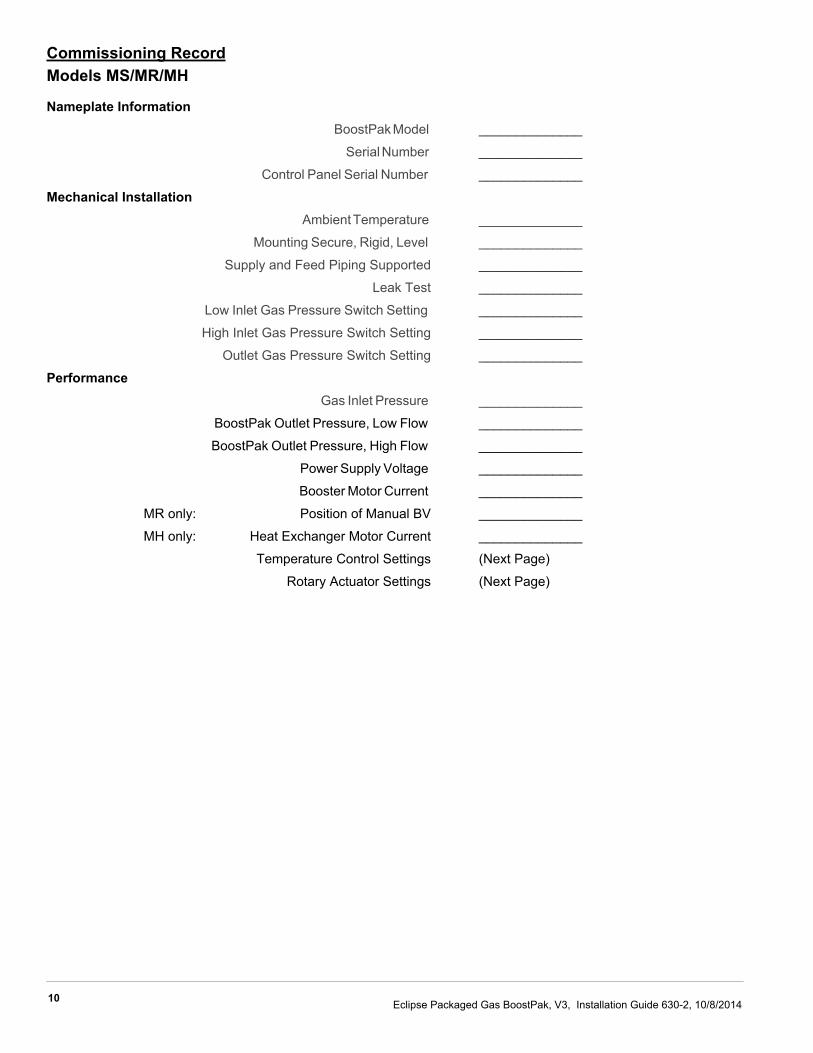
Commissioning RecordModels MS/MR/MH
Nameplate Information BoostPak Model ______________
Serial Number ______________
Control Panel Serial Number ______________
Mechanical Installation Ambient Temperature ______________
Mounting Secure, Rigid, Level ______________
Supply and Feed Piping Supported ______________
Leak Test ______________
Low Inlet Gas Pressure Switch Setting ______________
High Inlet Gas Pressure Switch Setting ______________
Outlet Gas Pressure Switch Setting ______________
Performance Gas Inlet Pressure ______________
BoostPak Outlet Pressure, Low Flow ______________
BoostPak Outlet Pressure, High Flow ______________
Power Supply Voltage ______________
Booster Motor Current ______________
MR only: Position of Manual BV ______________
MH only: Heat Exchanger Motor Current ______________
Temperature Control Settings (Next Page)
Rotary Actuator Settings (Next Page)
11Eclipse Packaged Gas BoostPak, V3, Installation Guide 630-2, 10/8/2014
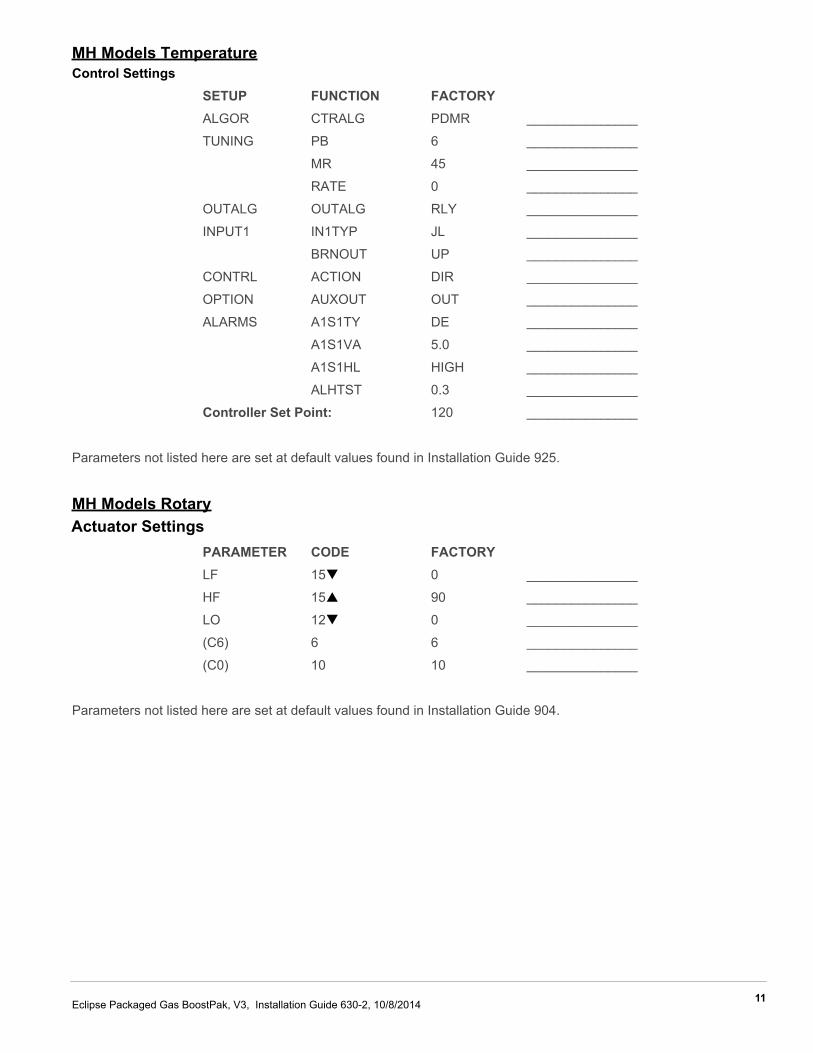
MH Models TemperatureControl Settings
SETUP FUNCTION FACTORYALGOR CTRALG PDMR _______________
TUNING PB 6 _______________
MR 45 _______________
RATE 0 _______________
OUTALG OUTALG RLY _______________
INPUT1 IN1TYP JL _______________
BRNOUT UP _______________
CONTRL ACTION DIR _______________
OPTION AUXOUT OUT _______________
ALARMS A1S1TY DE _______________
A1S1VA 5.0 _______________
A1S1HL HIGH _______________
ALHTST 0.3 _______________
Controller Set Point: 120 _______________
Parameters not listed here are set at default values found in Installation Guide 925.
MH Models RotaryActuator Settings
PARAMETER CODE FACTORYLF 15 0 _______________
HF 15 90 _______________
LO 12 0 _______________
(C6) 6 6 _______________
(C0) 10 10 _______________
Parameters not listed here are set at default values found in Installation Guide 904.
12 Eclipse Packaged Gas BoostPak, V3, Installation Guide 630-2, 10/8/2014
OperationIntroductionIn this chapter, you will find instructions on how to startand stop the booster system. Become familiar withbooster control methods before operating the equipment.
■ The BoostPak system, described herein, isdesigned to increase gas pressure to an appliance.All fuel handling devices are capable of producingfires and explosions if improperly applied,installed, adjusted, controlled, or maintained.
■ Do not bypass any safety feature; fire or explosioncould result. Never try to operate a BoostPak if itshows signs of damage or malfunction.
1. Be sure the inlet and outlet valves are open. On modelMH, make sure both heat exchanger isolation valvesare open.
2. Turn the main disconnect switch on.The green POWER ON light comes on.
3. Check for ALARM conditions and correct beforeproceeding.
4. Turn the control switch to AUTO.
The BoostPak is in operation.
• For Continuous Operation mode, the booster will run within 15 seconds of the switch operation.
• For Appliance On Demand mode, the booster will run within 15 seconds of the closure of the appliance run interlock contact.
The booster motor starter contact closes, the motor startsrunning, and the yellow BOOSTER ON light comes on.The LOW GAS light will flash on and off until the outlet gaspressure switch makes contact. If it does not make contactwithin 15 seconds, the red LOW GAS light comes onsteady and the alarm sounds.
Heat Exchanger Loop OperationFor model MH, the heat exchanger will operate when thetemperature sensed in the outlet pipe exceeds the setpoint and deviation alarm value, which is 125°F withfactory default settings. The temperature controlleradjusts the position of the automatic butterfly valve in the
heat exchanger loop to keep the outlet gas temperaturebelow this maximum value.
Alarm SilenceTo silence the alarm, press the ALARM SILENCE button.
ShutdownThe booster can be stopped by:
• Opening the run interlock contact (appliance dedicated control mode)
• Turning the control switch to off• Turning the main disconnect switch off
When shutting the system down to prevent operation, turnthe main disconnect switch off and turn off the main powersupply to the control panel.
DANGER
5
13Eclipse Packaged Gas BoostPak, V3, Installation Guide 630-2, 10/8/2014
Maintenance &Troubleshooting
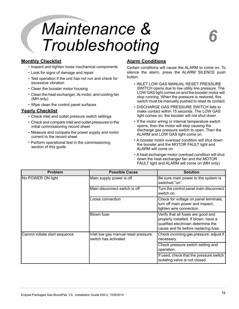
Monthly Checklist• Inspect and tighten loose mechanical components• Look for signs of damage and repair• Test operation if the unit has not run and check for
excessive vibration• Clean the booster motor housing• Clean the heat exchanger, its motor, and cooling fan
(MH only)• Wipe clean the control panel surfaces
Yearly Checklist• Check inlet and outlet pressure switch settings• Check and compare inlet and outlet pressures to the
initial commissioning record sheet• Measure and compare the power supply and motor
current to the record sheet• Perform operational test in the commissioning
section of this guide
Alarm ConditionsCertain conditions will cause the ALARM to come on. Tosilence the alarm, press the ALARM SILENCE pushbutton.
• INLET LOW GAS MANUAL RESET PRESSURE SWITCH opens due to low utility line pressure. The LOW GAS light comes on and the booster motor will stop running. When the pressure is restored, this switch must be manually pushed to reset its contact.
• DISCHARGE GAS PRESSURE SWITCH fails to make contact within 15 seconds. The LOW GAS light comes on; the booster will not shut down.
• If the motor wiring or internal temperature switch opens, then the motor will stop causing the discharge gas pressure switch to open. Then the ALARM and LOW GAS light come on.
• A booster motor overload condition will shut down the booster and the MOTOR FAULT light and ALARM will come on.
• A heat exchanger motor overload condition will shut down the heat exchanger fan and the MOTOR FAULT light and ALARM will come on (MH only).
Problem Possible Cause SolutionNo POWER ON light Main supply power is off Be sure main power to the system is
switched “on”.Main disconnect switch is off Turn the control panel main disconnect
switch on.Loose connection Check for voltage on panel terminals,
turn off main power and inspect, tighten wire connection.
Blown fuse Verify that all fuses are good and properly installed. If blown, have a qualified electrician determine the cause and fix before replacing fuse.
Cannot initiate start sequence Inlet low gas manual reset pressure switch has activated
Check incoming gas pressure: adjust if necessary.Check pressure switch setting and operation.If used, check that the pressure switch isolating valve is not closed.
6
14 Eclipse Packaged Gas BoostPak, V3, Installation Guide 630-2, 10/8/2014
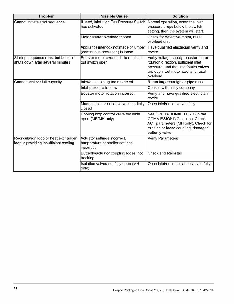
Cannot initiate start sequence If used, Inlet High Gas Pressure Switch has activated
Normal operation, when the inlet pressure drops below the switch setting, then the system will start.
Motor starter overload tripped Check for defective motor, reset overload unit.
Appliance interlock not made or jumper (continuous operation) is loose
Have qualified electrician verify and rewire.
Startup sequence runs, but booster shuts down after several minutes
Booster motor overload, thermal cut-out switch open
Verify voltage supply, booster motor rotation direction, sufficient inlet pressure, and that inlet/outlet valves are open. Let motor cool and reset overload.
Cannot achieve full capacity Inlet/outlet piping too restricted Rerun larger/straighter pipe runs.Inlet pressure too low Consult with utility company.Booster motor rotation incorrect Verify and have qualified electrician
rewire.Manual inlet or outlet valve is partially closed
Open inlet/outlet valves fully.
Cooling loop control valve too wide open (MR/MH only)
See OPERATIONAL TESTS in the COMMISSIONING section. Check ACT parameters (MH only). Check for missing or loose coupling, damaged butterfly valve.
Recirculation loop or heat exchanger loop is providing insufficient cooling
Actuator settings incorrect, temperature controller settings incorrect
Verify Parameters
Butterfly/actuator coupling loose; not tracking
Check and Reinstall.
Isolation valves not fully open (MH only)
Open inlet/outlet isolation valves fully.
Problem Possible Cause Solution
15Eclipse Packaged Gas BoostPak, V3, Installation Guide 630-2, 10/8/2014
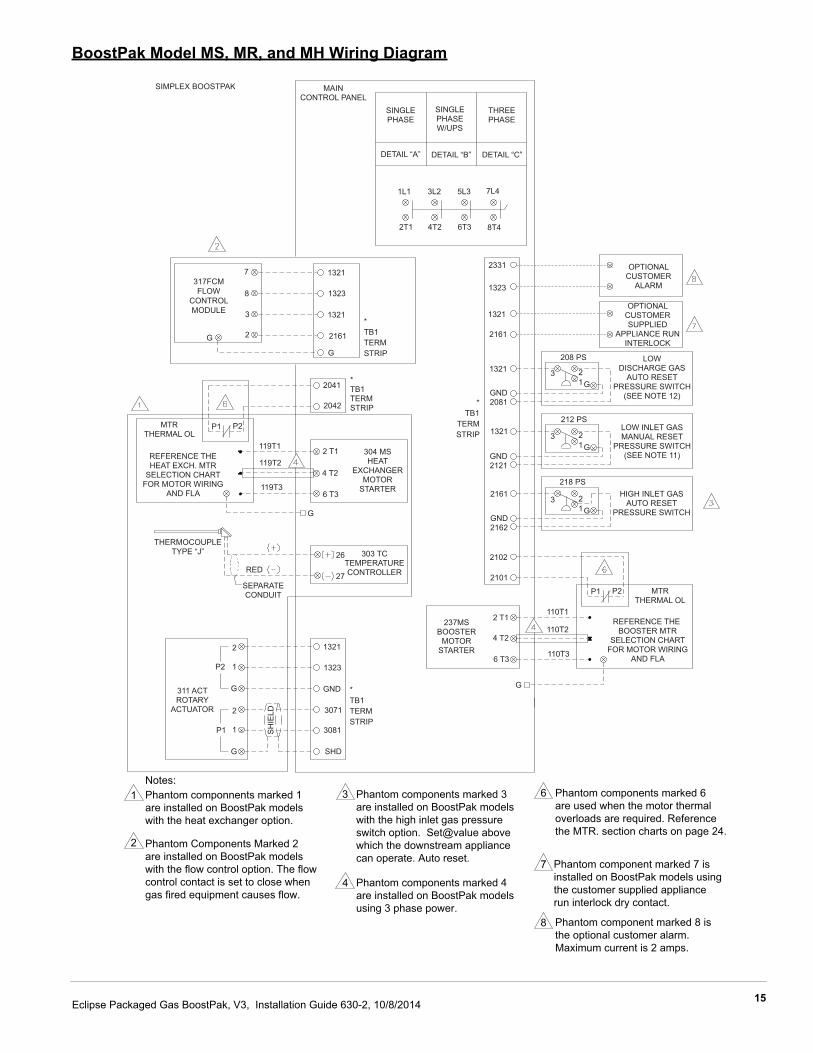
BoostPak Model MS, MR, and MH Wiring Diagram
Phantom componnents marked 1are installed on BoostPak modelswith the heat exchanger option.
Phantom Components Marked 2are installed on BoostPak modelswith the flow control option. The flowcontrol contact is set to close whengas fired equipment causes flow.
Notes:Phantom components marked 3are installed on BoostPak modelswith the high inlet gas pressureswitch option. Set@value abovewhich the downstream appliancecan operate. Auto reset.
Phantom components marked 4are installed on BoostPak modelsusing 3 phase power.
Phantom components marked 6are used when the motor thermaloverloads are required. Referencethe MTR. section charts on page 24.
Phantom component marked 7 isinstalled on BoostPak models usingthe customer supplied appliancerun interlock dry contact.
Phantom component marked 8 isthe optional customer alarm.Maximum current is 2 amps.
1
2
3
4
6
7
8
304 MSHEAT
EXCHANGERMOTOR
STARTER
7
8
3
2G
317FCMFLOW
CONTROLMODULE
1321
1323
1321
2161
G
*TB1TERMSTRIP
303 TCTEMPERATURECONTROLLER
311 ACTROTARY
ACTUATOR
1321
1323
GND
3071
3081
SHD
*TB1TERMSTRIP
*TB1TERMSTRIP
SIMPLEX BOOSTPAK MAINCONTROL PANEL
SINGLEPHASE
SINGLEPHASEW/UPS
THREEPHASE
DETAIL “A” DETAIL “B” DETAIL “C”
1L1 3L2 5L3 7L4
2T1 4T2 6T3 8T4
2331
1323
1321
2161
1321
1321
*TB1
TERMSTRIP
GND2081
GND2121
GND2162
2161
2102
2101
2041
2042
OPTIONALCUSTOMER
ALARM
OPTIONALCUSTOMERSUPPLIED
APPLIANCE RUNINTERLOCK
LOWDISCHARGE GAS
AUTO RESETPRESSURE SWITCH
(SEE NOTE 12)
LOW INLET GASMANUAL RESET
PRESSURE SWITCH(SEE NOTE 11)
HIGH INLET GASAUTO RESET
PRESSURE SWITCH
208 PS
212 PS
218 PS
237MSBOOSTER
MOTORSTARTER
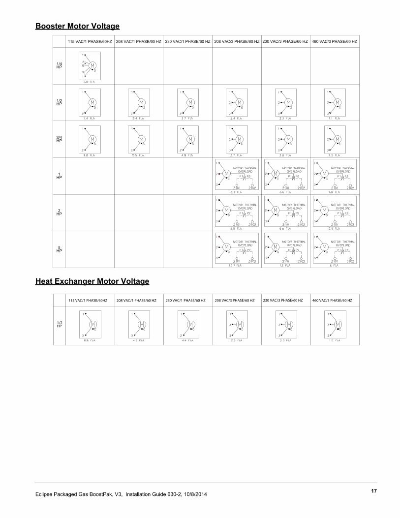
REFERENCE THE BOOSTER MTR
SELECTION CHARTFOR MOTOR WIRING
AND FLA
MTRTHERMAL OL
P1 P2
110T1
110T2
110T3
2 T1
4 T2
6 T3
G
3 21G
3 21G
3 21G
P2
P1
2
1
G
2
1
G
SH
IELD
SEPARATECONDUIT
RED
THERMOCOUPLETYPE “J”
MTRTHERMAL OL
REFERENCE THEHEAT EXCH. MTR
SELECTION CHARTFOR MOTOR WIRING
AND FLA
26
27
119T1
119T2
119T3
2 T1
4 T2
6 T3
G
P1 P2
16 Eclipse Packaged Gas BoostPak, V3, Installation Guide 630-2, 10/8/2014
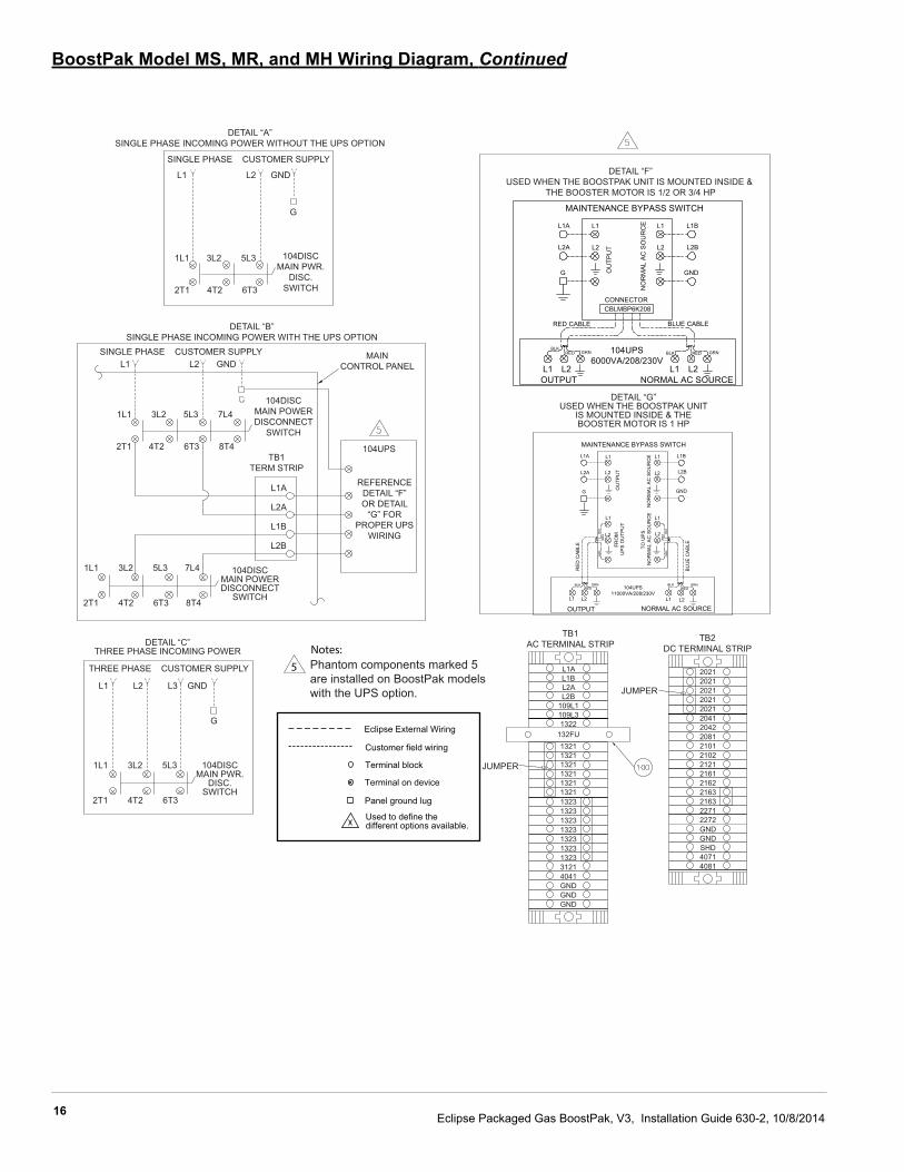
BoostPak Model MS, MR, and MH Wiring Diagram, Continued
Eclipse External Wiring
Customer field wiring
Terminal block
Terminal on device
Panel ground lug
Used to define thedifferent options available.
5Notes:
DETAIL “A”SINGLE PHASE INCOMING POWER WITHOUT THE UPS OPTION
DETAIL “B”SINGLE PHASE INCOMING POWER WITH THE UPS OPTION
DETAIL “F”USED WHEN THE BOOSTPAK UNIT IS MOUNTED INSIDE &
THE BOOSTER MOTOR IS 1/2 OR 3/4 HP
SINGLE PHASE CUSTOMER SUPPLY
104DISCMAIN PWR.
DISC.SWITCH
L1 L2 GND
G
1L1 3L2 5L3
2T1 4T2 6T3
SINGLE PHASE CUSTOMER SUPPLYL1 L2 GND
MAINCONTROL PANEL
104DISCMAIN POWERDISCONNECT
SWITCH
104UPS
REFERENCEDETAIL “F”OR DETAIL
“G” FORPROPER UPS
WIRING
1L1 3L2 5L3 7L4
2T1 4T2 6T3 8T4TB1
TERM STRIP
L1A
L2A
L1B
L2B
104DISCMAIN POWERDISCONNECT
SWITCH
1L1 3L2 5L3 7L4
2T1 4T2 6T3 8T4
DETAIL “C”THREE PHASE INCOMING POWER
THREE PHASE CUSTOMER SUPPLY
L1 L2 L3 GND
G
1L1 3L2 5L3
2T1 4T2 6T3
104DISCMAIN PWR.
DISC.SWITCH
DETAIL “G”USED WHEN THE BOOSTPAK UNIT
IS MOUNTED INSIDE & THEBOOSTER MOTOR IS 1 HP
Phantom components marked 5are installed on BoostPak modelswith the UPS option.
TB1AC TERMINAL STRIP
TB2DC TERMINAL STRIP
JUMPER
JUMPER
L1AL1BL2AL2B
109L1109L31322
132FU132113211321132113211321132313231323132313231323132331214041GNDGNDGND
20212021202120212021204120422081210121022121216121622163216322712272GNDGNDSHD40714081
104UPS6000VA/208/230V
MAINTENANCE BYPASS SWITCH
L1
CONNECTORCBLMBP6K208
BLK
L1
L2
L1
L2
NO
RM
AL
AC
SO
UR
CE
OU
TPU
T
L1A
L2A
G
L1B
L2B
GND
RED CABLE BLUE CABLE
BLK
BLK
GR
NR
ED
RE
DB
LKG
RN
L2 L1 L2
RED GRN BLK RED GRN
OUTPUT NORMAL AC SOURCE
OU
TPU
T
NO
RM
AL
AC
SO
UR
CE
TO U
PS
N
OR
MA
L A
C S
OU
RC
E
FRO
M
UP
S O
UTP
UT
RE
D C
AB
LE
BLU
E C
AB
LE
OUTPUT NORMAL AC SOURCE
104UPS11000VA/208/230V
L1A
L2A
G
L1B
L2B
GND
L1
L2
L1
L2
L1
L2
L1 L2 L2L1
MAINTENANCE BYPASS SWITCH
L1
L2
REDGRN BLK
REDGRN
17Eclipse Packaged Gas BoostPak, V3, Installation Guide 630-2, 10/8/2014
Booster Motor Voltage
Heat Exchanger Motor Voltage
115 VAC/1 PHASE/60HZ 208 VAC/1 PHASE/60 HZ 230 VAC/1 PHASE/60 HZ 208 VAC/3 PHASE/60 HZ 230 VAC/3 PHASE/60 HZ 460 VAC/3 PHASE/60 HZ
1/4HP
1/2HP
3/4HP
1HP
2HP
5HP
115 VAC/1 PHASE/60HZ 208 VAC/1 PHASE/60 HZ 230 VAC/1 PHASE/60 HZ 208 VAC/3 PHASE/60 HZ 230 VAC/3 PHASE/60 HZ 460 VAC/3 PHASE/60 HZ
1/2HP
18 Eclipse Packaged Gas BoostPak, V3, Installation Guide 630-2, 10/8/2014
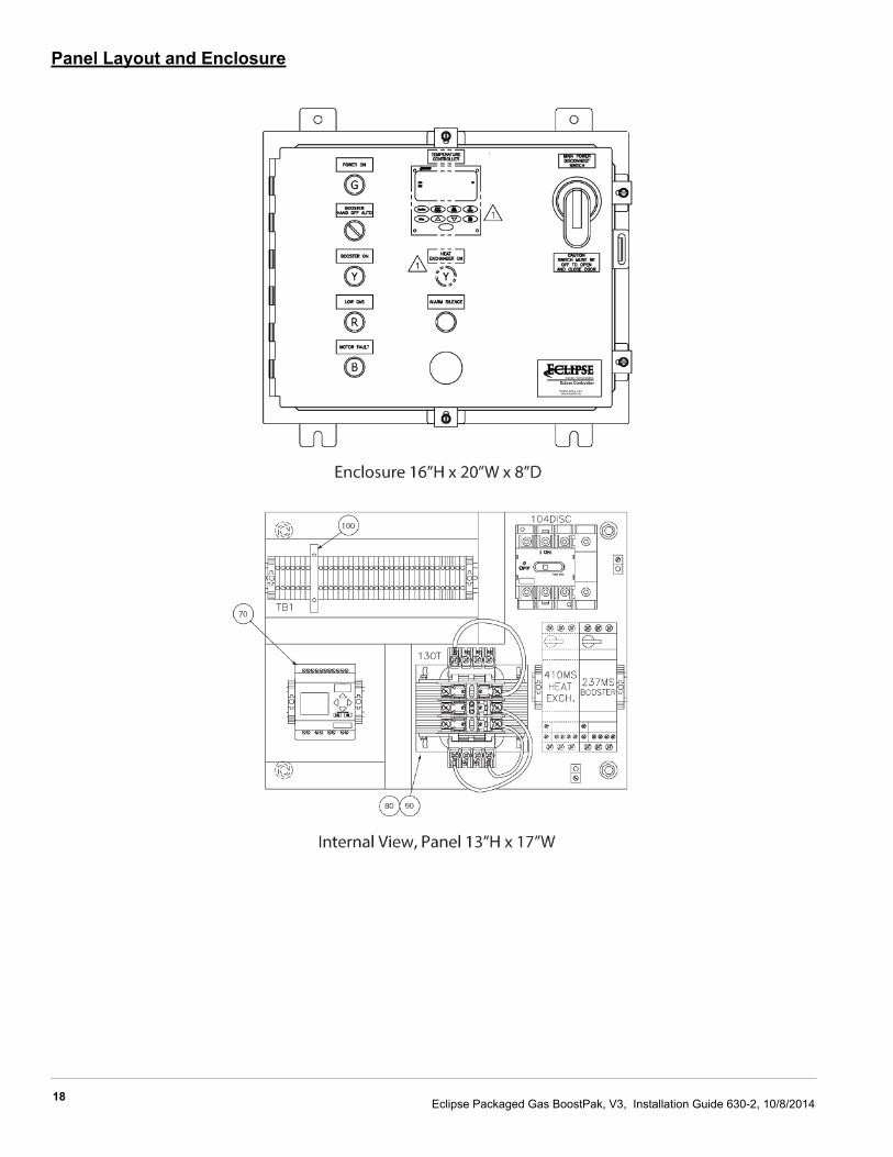
Panel Layout and Enclosure
19Eclipse Packaged Gas BoostPak, V3, Installation Guide 630-2, 10/8/2014
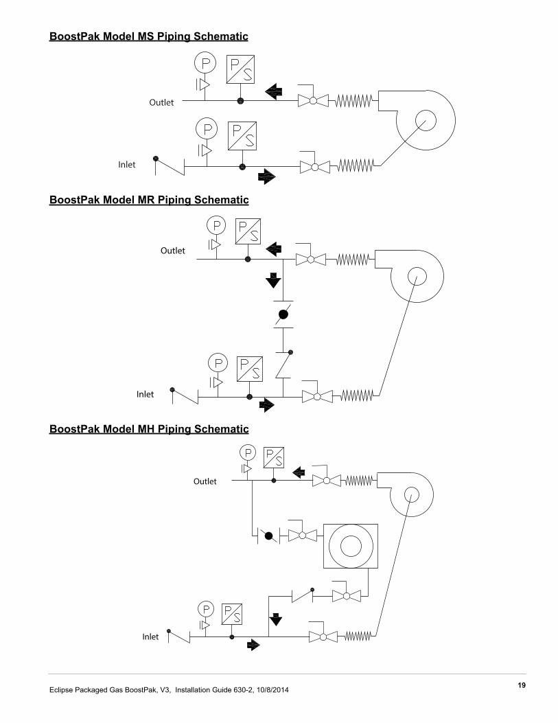
BoostPak Model MS Piping Schematic
BoostPak Model MR Piping Schematic
BoostPak Model MH Piping Schematic
Outlet
Inlet
Outlet
Inlet
Outlet
Inlet
i
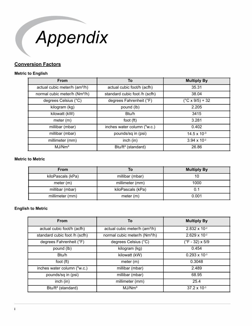
Conversion Factors
Metric to English
Metric to Metric
English to Metric
From To Multiply Byactual cubic meter/h (am³/h) actual cubic foot/h (acfh) 35.31normal cubic meter/h (Nm³/h) standard cubic foot /h (scfh) 38.04
degrees Celsius (°C) degrees Fahrenheit (°F) (°C x 9/5) + 32kilogram (kg) pound (lb) 2.205kilowatt (kW) Btu/h 3415
meter (m) foot (ft) 3.281millibar (mbar) inches water column ("w.c.) 0.402millibar (mbar) pounds/sq in (psi) 14.5 x 10⁻³
millimeter (mm) inch (in) 3.94 x 10⁻²
MJ/Nm³ Btu/ft³ (standard) 26.86
From To Multiply BykiloPascals (kPa) millibar (mbar) 10
meter (m) millimeter (mm) 1000millibar (mbar) kiloPascals (kPa) 0.1millimeter (mm) meter (m) 0.001
From To Multiply By
actual cubic foot/h (acfh) actual cubic meter/h (am³/h) 2.832 x 10⁻²
standard cubic foot /h (scfh) normal cubic meter/h (Nm³/h) 2.629 x 10⁻²
degrees Fahrenheit (°F) degrees Celsius (°C) (°F - 32) x 5/9pound (lb) kilogram (kg) 0.454
Btu/h kilowatt (kW) 0.293 x 10⁻³
foot (ft) meter (m) 0.3048inches water column ("w.c.) millibar (mbar) 2.489
pounds/sq in (psi) millibar (mbar) 68.95inch (in) millimeter (mm) 25.4
Btu/ft³ (standard) MJ/Nm³ 37.2 x 10⁻³
Appendix
ii
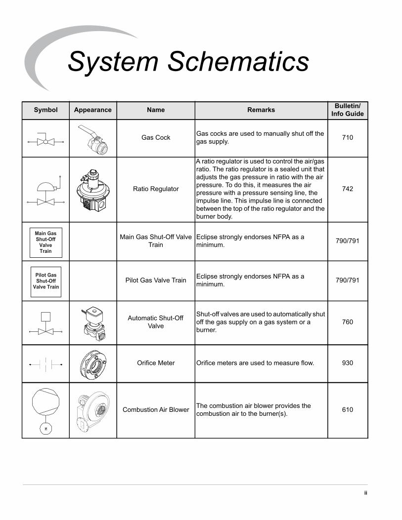
Symbol Appearance Name Remarks Bulletin/Info Guide
Gas Cock Gas cocks are used to manually shut off the gas supply. 710
Ratio Regulator
A ratio regulator is used to control the air/gas ratio. The ratio regulator is a sealed unit that adjusts the gas pressure in ratio with the air pressure. To do this, it measures the air pressure with a pressure sensing line, the impulse line. This impulse line is connected between the top of the ratio regulator and the burner body.
742
Main Gas Shut-Off Valve Train
Eclipse strongly endorses NFPA as a minimum. 790/791
Pilot Gas Valve Train Eclipse strongly endorses NFPA as a minimum. 790/791
Automatic Shut-OffValve
Shut-off valves are used to automatically shut off the gas supply on a gas system or a burner.
760
Orifice Meter Orifice meters are used to measure flow. 930
Combustion Air Blower The combustion air blower provides the combustion air to the burner(s). 610
Main GasShut-Off
ValveTrain
Pilot GasShut-Off
Valve Train
System Schematics
iii
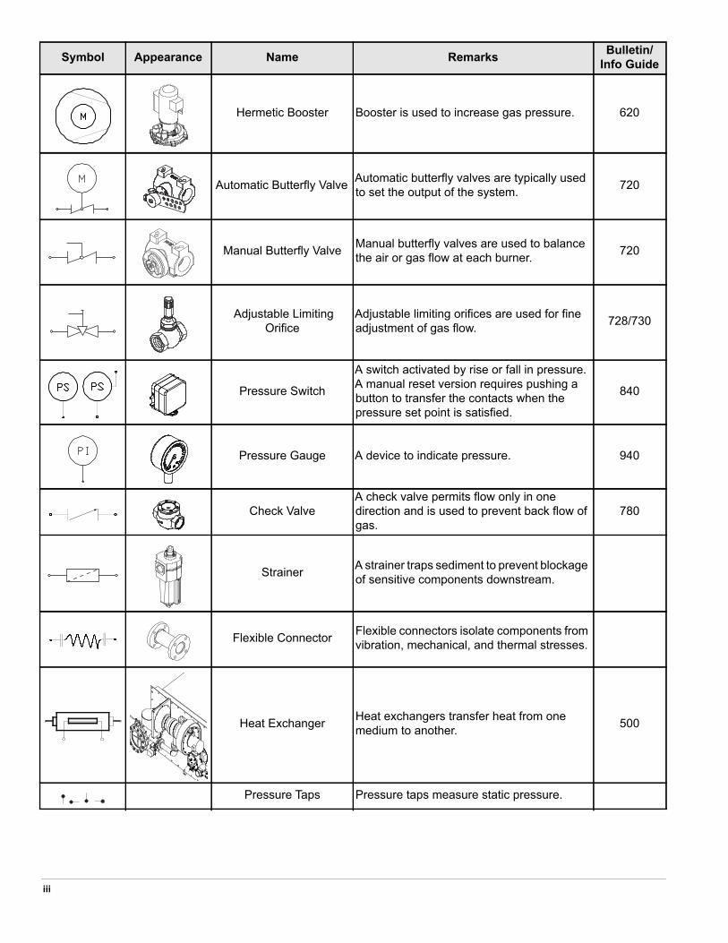
Hermetic Booster Booster is used to increase gas pressure. 620
Automatic Butterfly Valve Automatic butterfly valves are typically used to set the output of the system. 720
Manual Butterfly Valve Manual butterfly valves are used to balance the air or gas flow at each burner. 720
Adjustable Limiting Orifice
Adjustable limiting orifices are used for fine adjustment of gas flow. 728/730
Pressure Switch
A switch activated by rise or fall in pressure. A manual reset version requires pushing a button to transfer the contacts when the pressure set point is satisfied.
840
Pressure Gauge A device to indicate pressure. 940
Check ValveA check valve permits flow only in one direction and is used to prevent back flow of gas.
780
Strainer A strainer traps sediment to prevent blockage of sensitive components downstream.
Flexible Connector Flexible connectors isolate components from vibration, mechanical, and thermal stresses.
Heat Exchanger Heat exchangers transfer heat from one medium to another. 500
Pressure Taps Pressure taps measure static pressure.
Symbol Appearance Name Remarks Bulletin/Info Guide

Notes
ii

Installation Guide 630-2, 10/8/2014
© Eclipse, Inc. All Rights Reserved


![[XLS] · Web view400 630 630 400 630 990 990 630 630 630 630 990 990 990 990 990 990 400 400 990 630 990 630 630 400 990 990 990 990 990 630 630 990 990 630 630 990 990 990 990 990](https://img.dokumen.tips/doc/110x75/5af695027f8b9a5b1e8f4d8f/xls-view400-630-630-400-630-990-990-630-630-630-630-990-990-990-990-990-990-400.jpg)
![Redwood Anwendertage 2015 - Eclipse [Schreibgeschützt] · 2015. 5. 4. · Tipps & Tricks. Was ist Eclipse. Eclipse Eclipse(von englisch eclipse‚Sonnenfinsternis‘, ‚Finsternis‘,](https://img.dokumen.tips/doc/110x75/60e8ab6cf8fa6d37e6282437/redwood-anwendertage-2015-eclipse-schreibgeschtzt-2015-5-4-tipps-.jpg)