Embed Size (px)
Citation preview

I
A 6.3 Thermal Effects of GreasingDescription:
The high-strength steel wires that make up the pre-stressing tendons are very sensitive to stress corrosion cracking while undertension. Corrosion protection was initially done by grouting the inside of the tendon sleeves after tendon original stressing. However,NRC Reg1.107 (FM 6.3 Exhibit 1 is NRC RegGuide 1.107 Rev.1 from February 1977) and NRC Reg1.90 (FM 6.3 Exhibit 2 is NRCRegGuide 1.90 Rev. 1 from August 1977) moved the industry towards non-grouted tendons in order to fulfil in-service periodicinspections (FM 6.3 Exhibit 3 is a 1982 published paper by H. Ashar and D.J. Naus on the topic). From that time on, grease has beenused for corrosion inhibition of the stressed tendons.
The procedure to grease the tendon during original installation is described in FM 6.3 Exhibit 4 (part of the documentation generatedafter the dome delamination event in 1976) and observed in the examples of FM 6.3 Exhibit 5 (typical pre-stressing fielddocumentation including details of the greasing operation):
1. Install the tendons inside the sleeves (the sleeves themselves were installed as part of the concrete form-work and they areembedded in the concrete);
2. Tension the tendons to lock-off force (the details of the tensioning procedure are investigated in other failure modes);
3. Grease the tendons (basically done by filling the sleeves with grease, all around the tendons themselves);
The grease is injected in the tendon sleeves at a pressure up to 85psi and a temperature around 160oF (FM 6.3 Exhibit 4). Thepressure and temperature cause thermal expansion of the duct and of the concrete surrounding the duct. Differences in expansionand/or rate of expansion can induce thermal stresses and possibly cause cracking.
Additionally, the tendons are greased again during surveillance activities after they have been tested (FM 6.3 Exhibit 15).
2/23/10 G" f . . .- i... Page 1 of 4craf...t.1 L ..Ur......

Data to be collected and Analyzed:
1. Details of the original greasing procedure (FM 6.3 Exhibit 4 and FM 6.3 Exhibit 5);
2. Materials properties comparison (FM 6.3 Exhibit 6 is pp. 88-89 of P.K. Mehta reference book on concrete "Concrete: Structure,Properties, and Materials" and FM 6.3 Exhibit 7 is the summary of Coefficient of Thermal Expansion (CTE) values and FM 6.3Exhibit 8 is a summary of Thermal Conductivity values);
3. Calculate the heat transferred from the grease to the sleeve during tendon greasing (FM 6.3 Exhibit 9 is a thermal transfer analysisdone by P11);
4. Calculate pressure capability of the tendon sleeves (FM 6.3 Exhibit 10 is a sleeve pipe pressure calculation done by Progressenergy);
5. Calculate additional stress created by the grease injection at high temperature and pressure using first principles (FM 6.3 Exhibit12 is a P11 calculation of the stresses generated by the hot grease);
6. Investigate grease additions during surveillance activities (FM 6.3 Exhibit 15);
Discussion:
The files exampled in FM 6.3 Exhibit 5 are from the original installation of the post-tensioning tendons. They are the "Crystal River 3Reactor Building Pre-Stressing System Tendon History" files. The identification number is the number of the tendon in question.
The first example in FM 6.3 Exhibit 5 is tendon 12V2:
1. Tendon 12V2 is the second (2) Vertical tendon (V) between buttresses 1 and 2 (12), hence 12V2;
2. The tendon was received on-site on 1/16/1974;
3. And installed in the conduit (sleeve) on 7/3/1974;
2/23/10 Page 2 of 4
Draft 1 _ t "ion

4. No wires were removed or replaced;
5. The field anchor-head was button-headed on 8/27/1974;
6. And subsequently stressed on 10/14/1974;
7. All the elongation is on the same side as the vertical tendons are accessible only on the dome side for tensioning;
8. The total elongation is 12.5". This is the elongation from 1,500 psi (FM 6.3 Exhibit 5) or "an initial force that will remove all slack"(FM 6.3 Exhibit 13 chapter 1.0 Purpose), which was taken as 360 kips in practice (FM 6.3 Exhibit 13 chapter 3.0 Design Inputs).The theoretical elongation of 14.94 inches (FM 6.3 Exhibit 14) is longer than the actual elongation because of the wobblefriction in the wires (FM 6.3 Exhibit 13);
9. The grease is then filled on 10/23/1974;
10.At a pressure of 112 psi and a temperature of 1260F;
An important point to remember is that the issue of differential thermal expansion in this case is NOT associated with differentCoefficient of Thermal Expansions (CTE) between the two materials but with different Thermal Conductivity Coefficients between thesteel sleeve and the concrete. The sleeve expands much faster initially and this creates a load on the slowly heating and expandingsurrounding concrete (see FM 6.3 Exhibit 4 from the dome analysis).
We made the conservative assumption that all the heat~from the grease was transferred to the sleeve rather than using the study onheat transferred from the grease to the tendon sleeve (FM 6.3 Exhibit 9).
From observation of the tendon surveillance data, the number of greasing cycles is under 4 for all tendons, and it is 1 for most tendonsin the structure. Note that an analysis of potential tensile strength degradation due to thermal effects is included in FM 4.8.
2/23/10 -' , Page 3 of 4
Draft 1e ........ ... ..

Verified Supporting Evidence:
a. The Thermal Conductivity Coefficient of the steel and concrete are very different so that the sleeve expands much faster than theconcrete and this creates a force from the hot sleeve to the still-cold surrounding concrete (concrete 1 btu/ft/h/°F and steel 25btu/ft/h/°F from FM 6.3 Exhibit 8);
Verified Refuting Evidence:
a. Once the temperature has equilibrated at the sleeve/concrete interface, there is no thermal stress because the coefficient of
thermal expansion of the sleeve steel material and of the concrete are very similar (FM 6.3 Exhibit 6);
b. The pressure capability of the tendon sleeves is high enough to support the 85 psi grease injection pressure (FM 6.3 Exhibit 10);
c. Stress analysis demonstrates that the additional stresses added due to thermal effects of greasing in the concrete do not exceedthe concrete tensile capability (FM 6.3 Exhibit 12);
Conclusion:
The stresses due to high-temperature greasing did not lead to the delamination.They may have contributed to localized micro-cracking around the tendon sleeves.
2/23/10
Draft1PH1 Przprieta F~rif"ft'd 7 )p4-27fl--2 Page 4 of 4

Revision I
FM 6.3 Exhibit 1 page 1 of 7
U.S. NUCLEAR REGULATORY COMMISSION Rev1ion7
'REGULATORYGUIDE47OFFICE OF STANDARDS DEVELOPMENT
REGULATORY GUIDE 1.107
QUALIFICATIONS FOR CEMENT GROUTING FORPRESTRESSING TENDONS' IN -CONTAINMENT STRUCTURES
1.
A. INTRODUCTION
General Design Criterion 1. "Quality Standardsand Records." of Appendix A, "Gencral DesignCriteria for Nuclear Power Plants," to 10 CFR Part50, "'Licensing of Production and UtilizationFacilities," require that structures, systems, andcomponents important to safety be designed,fabricated, and erected to quality standards commen.surate with the.importance of the safety functions tobe perf6rmed.
The prestessing tendon system of a prestressed con.crete containment structure is a principal strengthelement of the structure. Since the ability of the con-tainment structure to withstand the events postulatedto occur during the life of the smtcture depends onthe functional reliability of the structure's principalstrength elements, any signiicant deterioration of theprestressed elements due to corrosion may presentTotential risk to the public safety. Hence it is impor..tent that any system for inhibiting corrosion of theprestressing elements possess a high degree ofreliability in performing its intended function.
This guide describes quality standards acceptableto the NRC staff for the use of portland cement groutas the corrosion inhibitor for prestressing tendons inprestressed concrete containment structures. The Ad-visory Committee on Reactor Safeguards has. beenconsulted concerning this guide and has concurred inthe regulatory position.
'For tbe Purpose Of Ibis gide. a -Mwao" is defned as agmiosuGW ade dmt consiedu of %TM tads. or barsnwchored at each end to an end anchorag awmbly.
* Lins idima i subtdvca d o•W peu ipo u=no
B. DISCUSSION
The recommend&,tions of this guide are applieablewhen portland cement grout is used as the corrosioninhibitor for the highly stressed tendons of prestres-sed concrete containment structures. The rcommen-dations of the guide are not intended for use in rela-tion to the grout for foundation anchors.
To date, the staff has evaluated applicationsproposing grout as the corrosion protection systemfor both bar tendons and strand tendons. The recom-mendations of this regulatory guide therefore applyto a grouted tendon system when the tendon isfabricated from either bars or strands. For groutingof wire tendons, a program based on similar qualitystandards may be developed and submitted to thestaff for evaluation.
Unlike greased tendons, pouted tendons are notavailable for direct inspection after they an grouted.It is therefore essential that the proposed grout andgrouting procedure be thoroughly evaluated before itis used in the construction of the containment struc-ture. An advantage of grouting, in addition toproviding corrosion protection. is that a well-designed and well-constructed grouted tendon systemprovides a degre of bond between the tendons endthe surrounding concrete. This bond in turn helps theanchorage system to resist the fluctuating stressesthat arise after construction of the structur.
Section i11. Division 2. "Code for Concrete Reac-tor Vessels and Containments," of the ASME Boilerand Pressure Vessel Code (Ref. I) provides some .e-quirments for grout constituents and for the
a-
1
/
USNRC REGULATORY GUIDES Co-"mm sum ibe Ca t 1mm,. Uao"ft av G'm -, O . 8 and 604 amW go ge Retuto CM01mmon. Waalmm. D.C. u. ARama.: SOeamel mlmlthodg amao to we f3stall "of aNR4emaesaig W"I4ft mans of me r tim ,COmmigAon mI ati . 20 do"---w-mct Ed 6 V staff m egv".q4" secif In psi*a or 00G'nued at O it I d at Te -Ide Wosau tn IM by0awmn tO bsted WwadoMmeSnig. agiata., Gad •ma ma nmabad•0i88 to, .aaeia. ai aau•I.Ihanca 1. Pow., Poglao'to 5. Pwgdu "Wil olim iS am atoiwgd. Moisoi WiSih•ibU, uIIFWWm bnmW thmoUt 5oW5tieO m0O m ov enshlnes • 5. I3maagtilaid ?as: Poact.o, 1. luaroqmtodia 5umdemudi ceaaI a~paao aabiafan.maumt. tof and Saunasmmen; Poedh~lias~ I. Oscmho.BSothut Rm Coo" W@nngo at atoft, ya a NKS jCommaisa ga t0 r Ws n olgis flCo4 £ MaavalPlamPmtoian 1i. o -eatsat at Srwoa. aid g#MWOM wll i*.s MWseul. sso, in Lclommodata sum-
g ae tO g aw mOmmn O amota. Wow,. eommenm en Cm at 0bpOWOW gd mv mie Obnd bs Teis memo's milkaa W.thu8 gala~. of ua.oead w~itS aou tew mims alo it u,,wNi a. dhwIe ~l- oaia Gagaea to Stn U.S. Saga., llegwaainty Cam~saaan. wakamgtoe. Sj..UcIt, aaluimeh me awinataigl Is madl Itim awe,• ta~me... Im. Alttntim: Ojeacee. Offc te Silarla• Sawatoomoem,
4,~~ ~ ~ ~ Inior~i OWamI ntntf

FM 6.3 Exhibit 1 page2 of7 ......
physical and -chemical properties of grout.Regulatory Position C.I of this guide brieflydescribes minimum quality standards for groutmaterials, referencing the ASME Code Articleswhere applicable and acceptable to the NRC staff.The regulatory position also outlines important con-siderations affecting proper grouting. References 2,3.and 4, as well as data furnished by applicants whohave proposed grout as the corrosion inhibitor forprestressing steel, have been used to arrive at thisposition.
Appendix A to this guide provides a list of relevantliterature that may be used by the applicant to es-tablish procedures and criteria for the specificgrouted tendon program. However, the listing ofthese references does not constitute a blanket en-dorsement by the staff of their content.
Specific areas of concern that should be givenproper attention during the development of a groutedtendon system are discussed 4n the followingparagraphs.
The effectiveness of grout in performing its in-tended function of inhibiting corrosion dependsmainly on two characteristics:
I. The grout (whether freshly mixed or hardened)should not cause chemical attack on the prestressingelements through its interaction with the material ofthe tendon steel, the material of the anchor hardware,or the material of the duct.:
2. The grout should completely fill the tendon ducton hardening.
Various deleterious substances have been reportedas potential sources of corrosion of prestressing steel.Most of the reported failures of prestressing elementshave been attributed (a) to the presence of chloridesin the atmosphere or in the constituents of grout or(b) to the presence of hydrogen sulfide in the at-mosphere (Refs. 5, 6. and 7). Nitrates and sulfatesgenerally found in mixing water have been theorizedto be potential sources of stress corrosion ofprestressing steel. However, it has been reported(Ref. 8)'that. in a concrete environment, oxygenated.anions such as sulfates and nitrates do not exhibit in-tense corrosion properties. It has also been reported(Ref. 3) that most of the chlorides are neutralizedduring the hydration of portland cement. Thethreshold values below which these substances willnot participate in initiating corrosion have not beenestablished. Henc a safe and prudent approachwould be to make sure that these substances arelimited to the lowest practical levels in grout con.stituents. The use of water contaminated with
I hydrogen sulfide should. be prohibited.
"For the purposes of this guide. a "duct" is a hole or voidprovided in the conetes for the post.tensioning tendon. A ductmay be provided by emaedding meai .heahinI in cat-in-placeconcrete.
The limits recommended for chlorides, nitrates,sulfates, and sulfides in Regulatory Position C.I.eshould not be exceeded in the overall composition ofthe grout. The quantities of these substances in thegrout constituents should be determined individuallyfor each of the constituents by the applicable ASTM(American Society of Testing and Materials)'methods and expressed in parts per million parts ofwater in the grout composition.
In general, portland cement conforming to ASTMCISO Type I or Type IL is suitable for the grout.However, grouting under certain climatic or en-vironmental conditions may dictate the use of othertypes of cements. Chlorides are normally present incement, but the amount is usually not reported. Thedetermination of chlorides in cement should be a re-quirement when specifying the cement for grout.
Admixtures should be free of any substance likelyto damage the prestressing steel. Use of aluminumpowder to produce expansion has been viewed bymany engineers as having possible deleterious effects.Under an alkaline environment (pH >9), thealuminum powder generates minute bubbles ofhydrogen gas (Hj) that would not endanger the ten-sioned steel at the prevailing range of pressures andtemperatures. However, the potential danger ofhydrogen attack on steel does exist if the tensioned'steel elements or stressed anchorage components con-tain surface flaws. The parameter affecting the use ofaluminum powder are described in Reference 9.
The protective mechanism of grout is primarilydependent on its ability to provide a continuousalkaline environment around the tensioned steel ele-ments. The natural alkalinity of the primary productof cement hydration (i.e., calcium hydroxide) tends tobe at a pH value of 12.5. The effectiveness of thealkaline environment may be reduced by the leachingof alkaline substances with water, by reaction in anacidic or sulfide-containing environment, or by thepresence of oxygen and chloride ions. It is reported inReference 10 that the ability of chloride ions todevelop corrosion increases with decreasingalkalinity of the calcium hydroxide solutions. Thus itis advisable to monitor the pH value of'the in-placegrout under actual field conditions and ensure that itremains above a value where the passivating effect ofthe grout is not reduced by the available chloride ionsin the composition of the grout.
Section CC-22432 of the ASME Code (Ref. 1) re-quires the use of flow cones with the limits on effluxtimes at the specific quiescent times to ensure ade-quate fluidity of the grout. However, for certain typesof grouts (in particular, one with a thixotropic ad-ditive), these requirements may not be appropriate todefine their pumpability. Applicants in such cases
3A lin of rlmivn ASTM standards b provided in Appendix B ofthis gide.
1.107-2

FM 6.3 Exhibit 1 page 3 of 7
I,
should propose alternative means of quality controlto accomplish the same objective. Also, a generalpractice is to limitthe pumping presur duringgrouting to 300 psi (set Refa. 2 and 3). However,grout with a thixotropic additive may need higherpumping pressures for long vertical tendons. In suchcases. it should be demonstrated through tests thathigh pressures will not deteriorate the quality ofgrout; damage the duct, duct splices, or surroundingconcrete; or deform the containment line.
1. Materials
a. Portland Cemenet.'Cement should conform tothe requirements of ASTM C150. The type to beselected should be suitable for the intended use.
b. Fbu Aggeqate. Fine aggregate-filler may beused when permitted by the requirements of ArticleCC-2243.1 of the ASME Boiler and Pressure VesselCode. Section I1i, Division 2 (Ref. 1).
c. Water. The water should not contain In-gredients harmful to the prestressing steel or thegrout. Water contaminated (I ppm) with hydrogensulfide (sulfide ion) should be prohibited. The waterto be used for grouting should be qualified for use bymaking comparative tests in accordance with the testmethods and tolerance levels described in Article CC-222.3.2 of the ASME Code.
In addition to the control on grout materials andon mixing and injecting the grout to ensure the in-tended protection of the prestressing steel, it is impor.tant to take other precautions directly related to thecorrosion protection of the prestressing steel:
1. It is necssay that the tendon remain clean, dry,free from deleterious corrosion, and undamaged upto the time it is grouted. Specific protection measuresshould be provided at coastal sites, at sites having ahigh moisture level, and at sites near industrial areas.
2. When a preassembied tendon-sheathing as-sembly is to be placed before concreting, the tendonshould be protected against corrosive environmentduring assembly, handling, storing. transporting,placing, and tensioning.
3. Before placing the tendon in the duct, it is im-portant to ascruin that the duct is free of obstuc-tions, moisture, and other deleterious substances.
4. Ferrous metal sheathing is galvanized to protectit against corrosion before grouting of the tendon.However, the contact surfaces of the tendons and thesheathing are potential areas for the formation ofcorrosion cells and hydrogen evolution. From thetendon corrosion point of view, this is critical if thetime between the tensioning and grouting is long andthe duct contains moisture with or withoutdeleterious substances.
5. In general, the period between tensioning andgrouting is critical from the standpoint of stress cor-rosion or hydrogen strs cracking. Steps should betaken to minimize this time period.
Effective corrosion protection of prestressingtendons can be provided by portland cement grout ifappropriate precautions are taken to eliminate thepotential sources of corrosion. To this end, closequality control is necessary for each constituent ofthe grout, the tendon material, and the tendon ductmaterial and for the method of mixing and pumpingthe grout and ensuring that the tendon is surroundedfrom end to end with qualified pout.
C. REGULATORY POSITIoN
The following minimum quality standards shouldbe maintained when portland cement grout is to beused for the corrosion protection of prestressing steel.
d. AdmUteu . Acceptable admixtmures may beused if tests have demonstrated that their useimproves the properties of grout, -e.g., increasesworkability, reduces bleeding, prevents water separa-tion when pumped at high pressure, entrains air, ex-pands the grout, or reduces shrinkage. The quantitiesof harmful substances in the admixture should bekept to a minimum. Use of calcium chloride shouldbe prohibited.
r. limits on Deleterious Substsns and pH.
(i) The quantity of the following substances(added Individually for each constituent and expres-sed as parts per million parts of water) in the overallgrout composition should not exceed the followinglimits:
I
Chloride
Nitrates
Sulfate
Sulfides
100 ppm(200 ppm if pH is maintainedabove 12)
100 ppm
250 ppm
2 ppm (test method of Ref. 15)
(2) The pH value of th grout at inlet and outletof the duct should be maintained above 11.6 (12 if theallowable chloride content is 200 ppm).
(3) During the gpouting period, the amount ofdeleterious substances in the grout constituentsshould be checked weekly and whenever the composi-tion of the constituents is changed or is suspece ofhaving changed.
* SuIwam in ft form of sulfur •wmid = a omponentned not be eonsidcr=
I
1.107-3

FM 6.3 Exhibit 1 page 4 of 7
2. Physical Properties of the Grout
The physical properties of the cement grout shouldsatisfy the requirements of Article CC.2243.2 of theASME Code. Adequate tests should be carried out inaccordance with the test methods described in thatarticle to demonstrate that the grout satisfies these re-quirements.
3. Duct
a. The duct size should be adequate to allow theinsertion and tensioning of tendons without unduedifficulty. The area of the grout that penetrates andsurrounds the tendon at any section should be at leastequal to the cross-sectional area of the tendon. Theduct sheathing and its splices should be of ferrousmetal and should be protected to prevent corrosivedeterioration prior to the grouting of tendons. Theduct sheathing and its splices should be sufficientlytight that a thin cement slurry cannot pass throughwhile the surrounding concrete is being placed. Theduct sheathing and its splices, when surrounded byhardened concrete, should be capable ofwithstanding the maximum grouting pressurewithout leakage.
should be protected from inclement weather andother adverse environmental conditions during thisperiod. If an additional delay is expected, the tendonsshould be protected by methods or productfithatwould not jeopardize the effectiveness of the grout asa corrosion inhibitor. In any case, the tendoil'anchorages should be visually examined just prior togpouting to detect any. breakage or degradation ofprestressing elements as evidenced by the movementor dislocation of anchoring hardware.
b. Fltshing before grouting is not recommended.When flushing has to precede the grouting, ap-propriate measures should be taken to ensure that:
(1) The level of harmful substances in the in-place grout does not increase above that in thedesigned grout. and
(2) The properties of the injected grout satisfythe recommendations in Regulatory Position C.2.
c. Tests should establish the length of time that thegrout can be used after mixing. The tests shouldverify that:
(1) The intended reaction of such admixtures asexpansive agents continues when such a grout is in-jected in the duct, and
(2) This time is less than that required for the in-itial set of the grout as determined by the method ofASTM C 191.
i.
• b. Vents should be provided at any major changesin section of the duct, as well as at the high points.Drains should be provided at the low points. Ventsand drains should be checked for possible- obstruc-tions prior to grouting.
4. Equipment for Grouting
a. The gpouting equipment should include a mixerthat is capable of continuous mechanical mixing andthat can produce a grout free of lumps and un-dispersed cement. To this end, tests should be per-formed to demonstrate the optimum range of mixingtime and the sequence of placing the constituentmaterials in the mixer under extreme anticipated en-vironmental conditions.
b. The pump should be of the positive displace-ment type and should be capable of exerting the re-quired maximum pressure. A safety device should beprovided to guard against exerting a pressure thatcould damage the duct, duct splices, or surroundingconcrete or deform the containment liner. The pumpsshould not suck air in with the grout.
c. A screen having clear openings not more than1/1 inch (1/4 inch for grout with a thixotropic ad-ditive) should be provided between the mixed groutand the pump to ensure that the grout does not con-tain lumps. If an excessive amount of lumps remainon the scren, the batch should be rejected.
5. Grouting
a. Grouting should be carried out immediatelyafter tensioning. The period between tensioning andgrouting should be kept below 72 hours. The tendon
d. The temperature along the entire length of the Itendon duct duinng grouting should be above 359F.This temperature should be maintained until theminimum (2-inch cube) strength of the job-curedgrout exceeds 800 psi. The grout temperature shouldnot exceed 900F during mixing and pumping unless itcan be established by test that a higher temperaturewill not adversely affect the grouting operation.
e. The. development of the grouting procedureshould consider the extremes of anticipated en-vironmental conditions. The procedure should ensurethat the ducts will be filled and that the tendon steelwill be completely surrounded by grout.
f. Aliaopenings, air vents, and drains should behermetically sealed after prouting to prevent the in-gress of water and other corrosive agents.
g. If an applicant chooses to provide permanentprotection of the anchor hardware by means ofqualified grout or concrete, the protection should beprovided on the following bases:
(1) Ali exposed anchor hardware should bethoroughly examined before being provided with the.permanent protection.
1.107-4

FM 6.3 Exhibit 1 page 5 of 7
.1'I
(2) The permanent protection should bedesigned and constructed in a manner that wouldprevent the intrusion of water and deleterious sub-stances to the anchorage components..
6. Tendon
The tendon should be clean, dry, 'free fromdeleterious corrosion, and undamaged up to the timewhen it is grouted. The pressembled tendonsheathing assembly should be protected against cor-rosive influences from the time of assembly to thetime of grouting.
D. IMPLEMENTATION
The purpose or this section is to provide informa-tion to applicants and licenses regarding the NRCstaff's plans for using this regulatory guide.
Except in those cases in which the applicantproposes an acceptable alternative method for com-plying with specif*ed portions of the Commission'sregulations. the guide will be used by the NRC staffon the following bases:
1. Submittals in connecion with construction per-mit applications docketed after February 14. 1977.will be evaluated on the basis of this guide.
2. Submittals in connection with operating licenseapplications for plants whose construction permit ap-plications were docketed prior to February 14. 1977.will be evaluated in accordance with the commitmentmade by the applicant in the construction permit.
2
1.107-5

FM 6.3 Exhibit 1 page 6 of 7
APPENDIX A
FtEFERENO!S
1. "Code for Concrete Reactor Vessels and Con-tainments," American Concrete Institute Committee359 and American Society of Mechanical EngineersSubcommittee on Nuclear Power, 1975. Copies maybe obtained from the American Society ofMechanical Engineers, 345 E. 47th St., New York,N.Y. 10017 or from the American Concrete Institute,P.O. Box 19150. Redford Station, Detroit, Mich.48219.
2. "Recommended Practice for Grouting of Post.Tensioned Concrete," Prestressed Concrete InstituteCommittee on Post-Tensioning. published in PCIJournal. Nov./Dec. 1972. Copies may be obtainedfrom the Prestressed Concrete Institute, 20 NorthWacker Drive, Chicago, IlL. 60606.
3. "Report on Grout and Grouting of PrestressedConcrete," Proceedings of the Seventh Congress ofthe Federation Internationale di la Precontraints.1974. Copies may be obtained from the FederationInternationale do ta Precontrainte, Terminal House.,Grosvenor Gardens. London SWIW OAU.
4. "Specifications for Structural Concrete forBuildings." American Concrete Institute Committee301. 1972. Copies may be obtained from theAmerican Concrete Institute` P.O. Box 19150, Red-ford Station. Detroit. Mich. 48219.
S. Leonhardt F.. Prutressed Concrete Design andConstinction. Wilhelm Ernst & Sohn, Berlin, SecondEdition. 1964.
6. Szilard, RL "Corrosion and Corrosion Protec-tion of Tendons in Prestressed Concrete Bridges,"ACI Journal, Jan. 1969. Copies may be obtainedfrom the American Concrete Institute, P.O. Box19150, Redford Station, Detroit, Mich. 48219.
7. Monfore, G. E., and Verbeck, G. J, "Corrosionof Prestressed Wire in Concrete," ACI Journal, July1960. Copies may be obtained from the addressshown in Reference 6.
8. Scott. G. N., "Corrosion Protection Propertiesof Portland Cement Concrete," Journal of theAmerican Water Works Association, Vol. 57, No. 8,
Aug. 1965. Copies may be obtained from theAmerican Water Works Association, 2 Park Avenue,New York, N.Y. 10016.
9. "Admixtures for Concrete," AmericanConcrete Instituts Committee 212. Copies may beobtained from the American Concrete Institute. P.O.Box 19150, Redford Station. Detroit, Mich. 48219.
10. Hausman, D. A., "Steel Corrosion inConcrete," Materlb Protection. November 1967.Copies may be obtained from the National Associa-tion of Corrosion Engineers, 2400 West Loop S.,Houston, Texas 77027.
11. Hartead, 0. A,, et aL "Testing for LargeCurved Prestessing Tendons," Proceedings of theAmerican Society of Civil Engineemr Power Division.March 1971. Copies may be obtained from theAmerican Society of Civil Engineers, 345 E. 47thStreet, New York, N.Y. 10017.
12. Lange, H-, "The Vacuum Process, A NewMethod for Injecting Prestressing Tendons," papersubmitted for the Seventh Congress or the FederationInternationale de Ia Precontrainte, New York, N.Y.1974. Copies may be obtained from the FederationInternationale do Is Precontrainte, Terminal House.Grosvenor Gardens. London SWIW OAU.
13. Schupack, M., "Development of a WaterRetentive Grouting Aid to Control the Bleed in Ce-ment Grout Used for Post-Tensioning," presented atthe Seventh Congress of the Federation Inter-nationale de Is Precontrainte, New York, N.Y., 1974.Copies may be obtained from the address shown inReference 12.
14. Kajfasz, S.. at al, "Phenomena Associated withGrouting of Large Tendon Ducts and Morphology ofDefects," technical contribution to the SeventhCongress of the Federation Internationale de laPrecontrainte, New York, N.Y. 1974. Copies may beobtained from the address shown in Reference 12.
15. "Standard Method for the Examination ofWater and Waste Wata"-1971. Copies may be ob-tained from American Public Health Association,1015 18th Street NW., Washington, D.C. 20036.
,\
1.107-6

-FM 6.3 Exhibit 1 page 7 of 7
APPENDIX B
LIST OF RELEVANT ASYM STANDARDS
'I C109-73, "Standard Method of Test for CompressiveStrength of Hydraulic Cement Mortars (Using2-in. Cube Specimens)"
C1S0-74, "Standard Specification for Portland Ce-ment Concrete"
C191-74, "Standard Method of Test for Tune of Set-ting Hydraulic Cement by Vicat Needle"
C260-74, "Standard Specifications for Air-Entraining Admixtures for Concrete"
C494-71, "Standard Specification for Chemical Ad.mixtures for Concret"
D512-67. "Test for Chloride Ion in Industrial Waterand Industrial Waste Watee"
D992-71. "Test for Nitrate Ion in Water"D516-74, "Tests for Sulfate Ion in Water"D596-74. "Pepordng Results of Analysis of Wate""D! 129-74. "Terms Relating to Water"D1293-65. "pH of Water and Waste Water"
1.107-7

FM 6.3 Exhibit 2 page 1 of 12
Revision 1IU.S. NUCLEAR REGULATORY COMMISSION August 1977
REGULATORY GUIDEOFFICE OF STANDARDS DEVELOPMENT
REGULATORY GUIDE 1.90
INSERVICE INSPECTION OF PRESTRESSED CONCRETECONTAINMENT STRUCTURES WITH GROUTED TENDONSt
A. INTRODUCTION
General Design Criterion 53, "Provisions for Con-.tainment Testing and. Inspection," of Appendix A,"General Design Criteria for Nuclear Power Plants,"to 10 CFR Part 50, "Licensing of Production andUtilization Facilities," requires, in part, that the con-tainment be designed to permit (1) appropriateperiodic inspection of all important areas and (2) anappropriate surveillance program. This guidedescribes, bases acceptable to the NRC staff fordeveloping an appropriate surveillance program forprestressed concrete containment structures withgrouted tendons. The Advisory Committee on Reac-tor Safeguards has been consulted concerning thisguide and has concurred in the regulatory position
B. DISCUSSIONInservice inspection of prestressed concrete con-
tainment structures with grouted tendons is needed toverify at specific intervals that the safety marginsprovided in the design of containment structures havenot been reduced as a result of operating and en-vironmental conditions. Grouting of tendons toprotect them against corrosion is a proventechnology in other types of structures. However,there is as yet no real experience to adequately definethe long-term characteristics of containment struc-tures with grouted tendons. The major concern incontainment structures with grouted tendons is thepossibility that widespread corrosion of the, tendonsteel may occur and remain undetected. The majorfactors influencing the occurrence of corrosion are (1)the susceptibility of the tendon steel to corrosion, (2)the degree of exposure of the tendon steel to a
* The substantial number of changes in this revision has made itimpractical to indicate the changes with lines in the margin.
t For the purpose of this guide, a tendon is defined as a tensionedsteel element consisting of wires, strands, or bars anchored at eachend to an end anchorage assembly.
deleterious environment, (3) the extent oftemperature variations, and (4) the quality of thegrout and its installation. Following the recommen-dations of Regulatory Guide .1.107, "Qualificationsfor Cement Grouting for Prestressing Tendons inContainment Structures," could significantly reducethe danger of widespread corrosion. However, themechanism of corrosion in all conditions and situa-tions is not fully understood. Because manyparameters can influence the development of corro-sion or stress corrosion, there is always an area of un-certainty with regard to the corrosion of tendon steel,and it is necessary to monitor the structure in a man-ner that would reveal the existence of widespread cor-rosion.
This guide outlines the recommendations for inser-vice inspection of containments having groutedtendons of sizes up to an ultimate strength of approx-imately 1300 tons (11,000 kN) and consisting eitherof parallel wires or of one or several strands. Thedetailed recommendations of the guide are not direct-ly applicable to grouted tendon containments havingbar tendons. However, the inservice inspectionprogram for grouted tendon containments with bartendons may be developed using the principles in thisguide and will be reviewed by the NRC staff on acase-by-case basis. This guide does not address the in-service inspection of prestressing foundation anchors.If they are used, the inservice inspection program willbe reviewed by the N RC staff on a case-by-case basis,Inservice inspection of the containment liner andpenetrations is also not addressed in this guide.
The simplest means of monitoring these prestres-sed concrete structures would be to ascertain theamount of prestress at certain strategically locatedsections in the structure. However, it is generally feltthat available instrumentation for concrete, i.e.,strain gages, stress meters, and strain meters, is notreliable enough to provide such information. When
USNRC REGULATORY GUIDES Comments should be sent to the Secretary of the Commission, US. Nuclear Regu.
Regulatory Guides are issued to describe and make available to the public methods latory Commission, Washington. D.C. 20555. Attention: Docketing and Service
acceptable to the NRC staff of implementing specific parts of the Commission's
regulations. to delineate techniques used by the stall in evaluating specific problems The guides are issued in the following ten broad divisions:or postulated accidents, or to provide guidance to applicants. Regulatory Guidesare not substitutes for regulations, and compliance with them is not required. I. Power Reactors 6. PrOductsMethods and solutions different from those set out in the guides will be accept- 2. Research and Test Reactors 7. Transportation
able if they provide a basis for the findings requisite to the issuance or continuance 3. Puels and Materials Facilities a. Occupational Healthof a per 4 r.nEironmental and Siting 9. Antitrust Review
mit or license by the Commission. 5. Materials and Plant Protection 10. General
Comments and suggestions for improvements in these guides are encouraged at all Requests for single copies of issued guides (which may be reproduredl or for place-times, and guides will be revised, as appropriate. to accommodate comments and ment on an automatic distribution list for single copies of future guides in specificto reflect new information or experience. This guide was revised as a result of divisions should be made in writing to the US. Nuclear Regulatory Commisson.,substantive comments received from the public and additional staff review. Washington, D.C. 20555, Altentioný Director. Division of Document Control.

FM 6.3 Exhibit 2 page 2 of 12
instrumentation that either can be recalibrated orreplaced in case of a malfunction or is proven to besufficiently reliable is developed, monitoring theprestress level would be a desirable means of assess-ing the continuing integrity of prestressed concretestructures with grouted tendons.
Another means of monitoring the functionality ofthe containment structure would be to subject it to apressure test and measure its behavior under pres-sure. Industry comments indicate that an inservice in-spection program based on the test of overall func-tionality is preferable.
This regulatory guide provides two acceptablealternative methods of inspecting containment struc-tures with grouted tendons: (1) an inservice inspec-tion program based on monitoring the prestress levelby means of instrumentation, and (2) an inservice in-spection program based on pressure-testing the con-tainment structure.
The detailed inspection program outlined in thisguide is applicable to a sphere-torus dome contain-ment having cylindrical walls about 130 feet (40 m) indiameter and an overall height of about 200 feet (61m) with three groups of tendons, i.e., hoop, vertical,and dome. For the purpose of this guide, such a con-tainment is termed the "reference containment." Therecommendations in the guide may be used forsimilar containments with cylindrical walls up to 140feet (43 m) in diameter and an overall height up to210 feet (64 m).
For containments that differ from the referencecontainment or are under a controlled environment,the inservice inspection program may be developedusing the concepts evolved in this guide and theguidelines in Appendix A.
The inservice inspection program recommended inthis guide consists of:
1. Force monitoring of ungrouted test tendons;2. Monitoring performance of grouted tendons by
a. Monitoring of prestress level, orb. Monitoring of deformation under pressure;
and
3. Visual examination.
1. FORCE MONITORING OF UNGROUTEDTEST TENDONS
Some tendons (otherwise identical) are left un-grouted and are protected from corrosion withgrease. The changes observed in these tendons are notintended to represent the changes due to environmen-tal or physical effects (with respect to corrosion) inthe grouted tendons. Instead, these test tendons willbe used as reference tendons to evaluate the extent of
concrete creep and shrinkage and relaxation of thetendon steel.
The measurement of forces in ungrouted testtendons would provide a quantitative means ofverifying the design assumptions regarding thevolumetric changes in concrete and the relaxation ofprestressing steel. If some lift-off readings (or loadcell readings) indicate values lower than the expectedlow values, checks should be made to determine ifsuch values are due to corrosion of wires of un-grouted tendons or to underestimation of prestress-ing losses. The plant need not be shut down or main-tained in a shutdown condition during such anevaluation period. These tendons may also serve asan investigative tool for assessing the structural con-dition after certain incidents that could affect thecontainment.
2. MONITORING ALTERNATIVES FORGROUTED TENDONS
a. Monitoring of Prestress Level (Alternative A)
After the application of prestress, the prestressingforce in a tendon decreases owing to the interactionof such factors as:
(1) Stress relaxation of the prestressing steel;
(2) Volumetric changes in concrete;
(3) Differential thermal expansion or contractionbetween the tendon, grout, and concrete; and
(4) Possible reduction in cross section of the wiresdue to corrosion, including possible fracture of thewires.
In this alternative, the prestress level is monitoredat certain strategically located sections in the contain-ment. Thus it is a sampling procedure in whichdegradation in the vicinity of the instrumented sec-tion will be detected by evaluation of the instrumen-tation readings. However, if corrosion occurs at loca-tions away from the instrumented sections, it wouldhave to produce gross degradation before the in-strumentation readings would be affected.
The prestressing force imparted to the structure bya grouted tendon system could be monitored by anappropriate combination of the following methods:
(I) Monitoring the tensile strains in the wires of atendon;
(2) Evaluating the prestress level at a section in thestructure from readings of appropriately locatedstrain gages or strain or stress meters at the section(see Refs. I through 7).
Method (1) above is useful for direct monitoring ofprestressing force in a tendon. However, the installa-
I
1.90-2

FM 6.3 Exhibit 2 page 3 of 12
lion of the instrumentation required for this methodneeds careful attention during installation andgrouting of the tendons. Moreover, strain gages in-stalled on the prestressing wires of a tendon will notdetect the loss of force due to relaxation of prestress-ing steel. Allowance for this can be based on relaxa-tion data for the prestressing steel used.
Evaluation of strain gage and stress meter readingsrequires a full understanding of what makes up thereadings, e.g., elastic, creep, and thermal strain orstress components. Strain gage readings will consistof elastic strains corresponding to the prestressingstress in concrete and strains due to creep andshrinkage of concrete.. Strains from creep andshrinkage of concrete can vary between 1.5 and 2.5times the elastic strains in concrete. However, thereare methods that can be used to isolate these effects.Three such methods are:
(1) Calculate average creep and shrinkage strainsfrom the time-dependent losses measured on the un-grouted tendons.
(2) Use stress meters at sections where strain gagesare used.
(3) Use special strain meters that respond only tovolumetric and temperature changes in concrete(Ref. 7).
A sufficient number of temperature sensors instal-led at the sections where instrumentation is locatedcan be useful in isolating the thermal effects. It isrecognized that the raw instrumentation readings canbe deceptive, and adjustments may be necessary toaccount for the calibration constants andtemperature effects. The interpretation and evalua-tion of the results will be simplified if the instrumen-tation is provided at sections away from structuraldiscontinuities. The applicant should provide suf-ficient redundancy in the instrumentation to permitthe evaluation of anomalous readings and the isola-tion of a malfunctioning gage. One such combinationwould be two strain gages and one stress meter ateach face of a section.
After appropriate use has been made of themethods and instruments available, an average stressand an average prestressing force at a section can beevaluated. Even though the predicted prestressingforce corresponding to a specific time may includeadequate consideration for creep of concrete andrelaxation of prestressing steel, the chance that thevalue based on measurements will compare well withthe predicted value is small. Hence it is recommendedthat an applicant establish a band of acceptableprestress level similar to that illustrated in Figure 1. Itis also recommended that the bandwidth not exceed8% of the initial prestressing force at a section afterconsidering the loss due to elastic shortening,
anchorage takeup, and friction. The 8% bandwidthwould amount to between 40% and 70% of the totaltime-dependent losses.
Alternative A is based on the use of instrumenta-tion. Many of these instruments have to be built intothe structure in such a manner that they can beneither replaced nor recalibrated. It is quite likelythat such built-in instrumentation may not remainreliably operable throughout the life of the structure.Recognizing such a possibility, the guide provides foran alternative of pressure testing (Alternative B)when the data obtained from instrumentationreadings are found to be questionable.
b. Monitoring of Deformation Under Pressure(Alternative B)
Testing the containment under pressure andevaluating its elastic response has been proposed as ameans of assessing the integrity of the containment.The elastic response under pressure testing is primari-ly a function of the stiffness of the structure. Anysignificant decrease in the stiffness of the structuredue to loss of prestress would be the result of crack-ing of the structure. Because of the insensitive and in-direct relationship, between the prestressing force andthe elastic response of the structure, such a methodcannot be used to establish the existing prestress levelat various sections. However, comparison of the con-dition and deformation of the structure during theISI (Inservice Inspection) pressure testing with thoseduring the ISIT (Initial Structural Integrity Testing)pressure testing could provide a basis for evaluatingthe functionality of the structure. This method hasbeen accepted* previously by the NRC staff on thecondition that the containment be designed conser-vatively so that there will be no cracking (or onlyslight cracking at the discontinuities) under the peaktest pressure. Section III, Division 2, of the ASMECode (Ref. 8) allows a 33-1/3% increase in the al-lowable stress in tensile reinforcement under a testcondition. The NRC staff has accepted this al-lowance on the assumption that it is only a one-timeloading (i.e., during the ISIT). However, if suchtesting is to be performed a number of times duringthe life of the containment structure, it is prudent notto use this allowance in order to avoid or minimizegradual propagation of cracking during subsequentpressure tests.
The locations for measuring the deformations un-der pressure should be based on the recommenda-tions of this guide. For a meaningful comparison ofthe deformations, it is recommended that the loca-tions where the deformations are to be recorded havedeformations larger than 0.06 inch (1.5mm) under thecalculated peak containment internal pressure as-sociated with the design basis accident and that these
* Three Mile Island Nuclear Power Station Unit 2 and ForkedRiver Nuclear Power Station.
1.90-3

FM 6.3 Exhibit 2 page 4 of 12
F. - Initial prestressing force at a section considering the losses due to
elastic shortening. anchorage takeup, and friction.
I PREDICTED PRESTRESS FORCE
(CONSIDERING LOW TIME-DEPENDENT LOSSES)
0
Uj
0o
1 3 5 10 15 20 25 30 35 40
TIME IN YEARS
Figure 1. Typical Band of Acceptable Prestress Level
//

FM 6.3 Exhibit 2
locations be approximately the same during the ISITand the subsequent ISIs. This will require these loca-tions to be away from the areas of structural discon-tinuities. Thus the number of locations for measure-ment of deformations in typical cylinder and domeareas will be in excess of those recommended inRegulatory Guide 1.18, "Structural Acceptance Testfor Concrete Primary Reactor Containments."
If an analysis of the effects of such parameters asnormal losses in prestressing force, increase inmodulus of elasticity of concrete with age, and dif-ferences in temperatures during various pressure testsindicates that they could affect the deformations ofthe selected points, these parameters should be con-sidered in comparing the deformations duringvarious pressure tests.
3. VISUAL EXAMINATION
Visual examination of structurally critical areasconsisting of the areas of structural discontinuitiesand the areas of heavy stress concentration is recom-mended. Reference 9 provides excellent guidance forreporting the condition of concrete and should beused whenever applicable for reporting the conditionof examined areas.
There are numerous examples of the use of pulsevelocity technique to obtain information concerningthe general quality level of concrete. Based on ex-perience and experimental data (Refs. 10, 11, 12), apulse velocity of 14,000 ft/sec (4300 m/sec) or higherindicates a good to excellent quality of concrete. Fornormal weight concrete, a pulse velocity of 11,000ft/sec (3400 m/sec) or lower indicates concrete ofquestionable quality. Thus the technique can be usedas part of the inspection of concrete containmentswhen the visual examination reveals a high density ofwide (>0.01 in. or 0.25 mm) cracks or otherwiseheavy degradation. The detailed procedure andlimitations of the techniques are described inReference 13.
page 5 of 12
3. The inservice inspection program should consistof:
a. Force monitoring of ungrouted test tendons;
b. Periodic reading of instrumentation for deter-mining prestress level (Alternative A) or deforma-tions under pressure (Alternative B) at preestablishedsections; and
c. Visual examination.
4. The inservice inspection should be performed atapproximately 1, 3, and 5 years after the initial struc-tural integrity test and every 5 years thereafter.However, when an applicant chooses pressure testing(Alternative B) as a part of the inspection, the fre-quency of inspections should be as indicated inFigure 2.
5. Alternative B may be substituted for AlternativeA by the applicant if, at some time during the life ofthe structure, the inspection based on Alternative Adoes not provide satisfactory data. The details ofsuch a substitution will be reviewed by the NRC staffon a case-by-case basis.
6. If the containment base mat is prestressed, itsproposed inspection program will be evaluated by theNRC staff on a case-by-case basis.
2. UNGROUTED TEST TENDONS
1. The following ungrouted test tendons should beinstalled in a representative manner:
a. Three vertical tendons,
b. Three hoop tendons, and
c. Three dome tendons for the design utilizingthree 600 families of tendons.
2. The ungrouted test tendons need not be in'addi-tion to the design requirements.
3. The ungrouted test tendons and theiranchorage hardware should be identical to thegrouted tendons and their hardware.
4. The ungrouted test tendons should be subjectedto force measurement by lift-off testing or load cellsto assess the effects of concrete shrinkage and creepand relaxation of the tendon steel. These data shouldbe evaluated in conjunction with the overall struc-tural condition of the containment evident from theother examinations.
C. REGULATORY POSITION
I. GENERAL
1. All prestressed concrete containment structureswith grouted tendons should be subjected to an inser-vice inspection (ISI) program. The specific guidelinesprovided herein are for the reference containmentdescribed in Section B.
2. For containments that differ from the referencecontainment, the program described herein shouldserve as the basis for developing a comparable inser-vice inspection program. Guidelines for the develop-ment of such a program are given in Appendix A tothis guide.
1.90-5

FM 6.3 Exhibit 2 page 6 of 12
I LRTdlcrt II a - I1 I
0 1 -1 -1 -- amj ý I -A Do I . -1 1-0- - I
(10 CFR Part 50,APP. J)
I I I II 1* ____________ - 1-1-I r
ISI SCH. 11111i=I- iPRESSURE
LEVELS
IPN
II
15 PD1.-I
IIPA
I L__________ __________£ ________A._
0 1 5 10 15 20 25 30 35
9•TIME AFTER ISIT - YEARS
KEY
PN - Normal Operating Pressure or Zero
PO - Containment Design Pressure
PA - Calculated Peak Internal Pressure Associated with the Design Basis Accident
ILRT- Integrated Leak Rate Testing
ISIT - Initial Structural Integrity Testing
IS[ - Insece Inspection
Figure 2. Schedule for Inservice Inspections (Alternative B)

FM 6.3 Exhibit 2
3. MONITORING ALTERNATIVES FORGROUTED TENDONS
3.1 Instrumentation for Monitoring the Prestress
Level (Alternative A)
3.1.1 Installation
1. The prestressed cylindrical wall and domeshould be instrumented. This instrumentation may beeither embedded in the concrete or inserted into thestructure so that it can be maintained or replaced.Instrument types, locations, and quantities should beselected to provide the best representation ofprestress level in the structure. A sufficient number oftemperature sensors should be installed to isolate andevaluate the effects of variations in temperaturegradients on the instrument readings and observa-tions. Redundancy of the embedded instrumentationshould be based on a conservative estimate of theprobability of malfunction of the instrumentation tobe installed.
2. The instrumentation in the concrete should bearranged and distributed in such a manner as to per-mit evaluation of the prestressing levels and shouldbe located:
a. At.six horizontal planes to measure the hoopprestressing levels;
b. Along three vertical tendons to measure ver-tical prestress levels;
c. Along three dome tendons for the design us-ing three families of 60' tendons.
3. Sections through the structure should beselected- at a minimum of four locations in eachhorizontal plane, three locations along each verticaltendon, and two locations along each dome tendon(see Figure 3). At these sections, the prestress levelshould be monitored by (a) a combination of stressmeters or strain gages in concrete or on rebar at aminimum of two points through the section or (b)strain gages directly on tendon wires with a minimumof 3% of the tendon wires instrumented.
3.1.2 Characteristics
1. Instrumentation provided for the determinationof concrete prestress level should be capable of effec-tive use over the life span of the containment struc-ture within specified operational limits under the fol-lowing conditions, unless otherwise defined by thedesigner and approved by the NRC staff:
a. Humidity: 0% to 100%;
b. Temperature: 00 F (-18°C) to 200'F (93*C);
page 7 of 12
c. Cyclic loading: 500 cycles of 600 psi (4.2MPa) stress variation in compression.
2. The instruments should be protected againstadverse effects of the expected environment in whichthey will be located, e.g., electrolytic attack, includingthe effects of stray electric currents of a magnitudethat may be encountered at the particular site andstructure. They should be protected againsttemperature extremes to which they may be exposedwhile the containment is under construction.
3. The sensitivity of strain gages should bespecified; the drift or stability under the conditions inI and 2 above should be accounted for in thespecified limits, or the gages should be subject torecalibration in service.
4, The stress meters should be able to measure
compressive stresses up to 2500*psi (17.2 MPa).
3.1.3 Monitoring Instrumentation Operability
After the installation of the instrumentation, allembedded strain gages and stress meters should beread every two months until the initial structural in-tegrity test (ISIT) is performed. The response of theinstrumentation during prestressing and pressuretesting (ISIT)' should be used, to confirm theiroperability. After the ISIT, the monitoring of the in-strumentation should be continued every two monthsto confirm operability of the instrumentation untilthe first inservice inspection. The monitoring fre-quency may be reduced to once every six monthsthereafter unless local conditions or special circum-stances dictate more frequent readouts. Theoperability of the instrumentation should also beconfirmed during subsequent pressure tests. Ifanomalous readings are obtained, the reason for suchreadings should be determined. If it is determinedthat they result from defective gages, 'the basis forsuch a determination should be justified.
3.2 Monitoring Deformation Under Pressure (Alter-native B)
When it is planned to use this alternative as a partof the total inservice inspection program, it is recom-mended that the design of the containment structureinclude the following considerations:
1. Membrane compression should be maintainedunder the peak pressure expected during the ISI tests.
2. The maximum stress in the tensile reinforcingunder the peak pressure expected during the ISI testshould not exceed one-half the yield strength of thereinforcing steel (0.5fy).
3.2.1 Pressurization
1. During the first inspecticn, the containmentstructure need not be pressurized.and
1.90-7

FM 6.3 Exhibit 2page 8 of 12
DT-1
DOME TEND
o0
VI-1 VT-1 VI-2 VT-2 VI-3 VT-3
DT-2
DI-2
DT-3
ONS AT 600
KEY
HT, VT, DT - HOOP, Vertical, DomeHT-1 Ungrouted Test Tendons.
HI - Horizontal Planes to be Selectedfor Instrumentation.VI & DI - Vertical & Dome Tendons
HT-2 to be Identified for Instrumentation.Four Sections Along HI Planes, ThreeSections Along VI Tendons, Two SectionsAlong DI Tendons to be Selected forMonitoring Prestress Level.
HT-3 *- Shows Selection of Sections AlongOne Horizontal Plane, One Vertical Tendon,and One Dome Tendon.
~HI-1- -- I - -- I~m.I-I
HI-2 I- -.- i
1112 -I -- I,- --
- HI-3 - I I
HI-4 - I
HI-6- - - -
15007
2700300
CONTAINMENT CYLINDER - DEVELOPED
Figure 3. Containment Diagram Showing Typical Locationsof Test Tendon'>-=-I Instrumentation

FM 6.3 Exhibit 2 page 9 of 1-2
2. During the second and third inspections, thecontainment structure should be subjected to a max-imum internal pressure, of 1.15 times the containmentdesign pressure.
3. During the fourth and subsequent inspections,the containment structure should be -subjected to amaximum internal pressure equal to the calculatedpeak internal pressure associated with the postulateddesign basis accident.
3.2.2 Instrumentation and Deformations
-1. Instrumentation similar to that used during theISIT should be installed prior to the pressure testingfor measurement of 'overall deformations at theselected points.
2. The limit of accuracy of readings of the instru-ments to be used should be specified by means of anerror band so that a meaningful comparison of defor-mations measured during the ISIT and ISI can bemade.
3. The points to be instrumented for the measure-ment of radial displacements should be determined insix horizontal planes in the cylindrical portion of the.shell, with a minimum of four points in each plane(see Figure 3).
4. The points to be instrumented for the measure-ment of vertical (or radial) displacements should bedetermined as follows:
a. At the top of the cylinder relative to the base,at a minimum of four approximately equally spacedazimuths.
b. At the apex of the dome and one intermediatepoint between the apex and the springline, on at leastthree equally spaced azimuths.
5. The intermediate pressure levels at which thedeformations at the selected points are to bemeasured should correspond to those for the ISIT.
4. VISUAL EXAMINATION
4.1 Structurally Critical Areas
A visual examination should be performed on thefollowing exposed structurally critical areas:
1. Areas at structural discontinuities (e.g., junctionof dome and, cylindrical wall or wall and base mat).
2. Areas around large penetrations (e.g., equip-ment hatch and air locks) or a cluster of smallpenetrations.
3. Local areas around penetrations that transferhigh loads to the containment structure (e.g., aroundhigh-energy fluid system lines).
4. Other areas where heavy loads are transferredto the containment structure (crane supports, etc.).
A visual examination of structurally critical areasshould be scheduled during all pressure tests whilethe containment is at its maximum test pressure, evenif visual examinations of these areas have been con-ducted at other times.
4.2 Anchorage Assemblies
Exposed portions of the tendon anchorage as-sembly hardware or the permanent protectionthereon (whether it be concrete, grout, or steel cap)should be visually examined by sampling in the fol-lowing manner:
1. A minimum of six dome tendons, two located ineach 600 group (three families of tendons) and ran-domly distributed to provide representative sampl-ing,
2. A minimum of five vertical tendons, randomlybut representatively distributed,
3. A minimum of ten hoop tendons, randomly butrepresentatively distributed.
For each succeeding examination, the tendonanchorage areas to be examined should be selected ona random but representative basis so that the samplegroup will change each time.
The inservice inspection program should define thedefects the inspector should look for during visual ex-amination of the exposed anchor hardware andprotection medium and should establish the cor-responding limits and tolerances. Special attentionshould be given to the concrete supporting the anchorassemblies, and any crack patterns at these pointsshould be observed and analyzed.
5. REPORTABLE CONDITIONS
5.1 Inspection Using Alternamive A
If the average prestress force along any tendon fallsbelow the acceptable band (see Figure I), the condi-tion should be considered as reportable.
If the prestress force determined at any section fallsbelow the design prestress force, the condition shouldbe considered as reportable.
5.2 Inspection Using Alternative B
If the deformation measured under the maximumtest pressure at any location is found to have in-
1.90-9

FM 6.3 Exhibit 2 page 10 of 12
creased by more than 5% of that measured during theISIT under the same pressure, the condition shouldbe considered as reportable.
5.3 Reportable Conditions for Visual Examinations
If the crack patterns observed at the structurallycritical areas indicate a significant decrease in thespacing or an increase in the widths of cracks com-pared to those observed during the ISIT at zero pres-sure after depressurization, the condition should beconsidered as reportable.
If the visual examination of the anchor hardwareindicates obvious movements or degradation of theanchor hardware, the condition should be consideredas reportable.
If the anchor hardware is covered by permanentprotection and the visual examination reveals adegradation (e.g., extensive cracks or corrosionstains) that could bring into, question the integrityand effectiveness of the protection medium, the con-dition should be considered-as reportable.
5.4 Reportable Conditions for Ungrouted TestTendons
When the force monitoring (by liftoff or load cell)of ungrouted test tendons indicates a prestress forcebelow the acceptable band (see Figure 1), the condi-tion should be considered as reportable.
6. REPORTING TO THE COMMISSION
The reportable conditions of Regulatory PositionC.5 could be indicative of a possible abnormal de-gradation of the containment structure (a boundarydesigned to contain radioactive materials). Any suchcondition should be reported to the Commission.*
D. IMPLEMENTATION
The purpose of this section is to provide informa-tion to applicants and licensees regarding the NRCstaff's plans for using this regulatory guide.
Except in those cases in which the applicantproposes an acceptable alternative method for com-plying with specified portions of the Commission'sregulations, the method described herein will be usedin the evaluation of submittals in connection withconstruction permit applications docketed afterOctober 1, 1977.
If an applicant wishes to use this regulatory guidein developing submittals for applications docketed onor before October 1, 1977, the pertinent portions ofthe application will be evaluated on the basis of thisguide.
* The report to the Commission should be made in accordancewith the recommended reporting program of Regulatory Guide1.16, "Reporting of Operating Information-Appendix ATechnical Specifications."
I
1.90-10

page 11 of 12FM 6.3 Exhibit 2
APPENDIX A
GUIDELINES FOR DEVELOPING THE INSERVICE INSPECTION PROGRAM FORCONTAINMENTS (OTHER THAN REFERENCE CONTAINMENT DISCUSSED IN
THE GUIDE) WITH GROUTED TENDONS
Ungrouted Tendons
Three ungrouted tendons should be provided ineach group of tendons (e.g.,vertical, hoop, dome, in-verted U).
Instrumentation (Alternative A)
The following criteria should be used to determinethe number of sections (N) to be monitored for eachgroup of tendons:
Actual Area Prestressed by a Group of TendonsK x Area Monitored by a Set of Instruments
at a Section (determined as SxL)
where
S = spacing of tendons in feet (meters)
L = length of a tendon monitored by a set ofinstruments- may be considered as 12 ft (3.66m)
and K is determined as follows:
For containments under uncontrolled environment
and having continuous tendon curvature,
K !S100
For containments under uncontrolled environmentand having essentially straight tendons,
K<160
For containments under controlled environmentand having either straight or curved tendons.
K<200
Monitoring Deformations Under Pressure (Alternative B)
The number of locations (N) to be selected formeasuring the deformations under pressure should bedetermined as follows:
For radial deformations of cylinder,
Surface Area of Cylinder injsquare feet(square meters)I
N =2700 (250)
but not less than 12..
For vertical deformations, of cylinder,
N-=4
For radial or vertical deformations of dome,
Surface Area of Dome in square feetN =(square meters)
2700 (250)
but not less than 4
1.90-11

FM 6.3 Exhibit 2 page 12 of 12
APPENDIX B
REFERENCES
I. Jones, K., "Calculation of Stress from Strain inConcrete," U.S. Department of Interior, Bureau ofReclamation, Oct. 1961. Copies may be obtainedfrom the Bureau of Reclamation, Denver FederalCenter, Denver, Colorado.
2. Irving, J., "Experience of In-service Surveillanceand Monitoring of Prestressed Concrete PressureVessels for Nuclear Reactors," a paper presented atInternational Conference on Experience in theDesign, Construction and Operation of PrestressedConcrete Pressure Vessels and Containments forNuclear Reactors, University of York, England,Sept. 1975. Copies may be obtained from J. C.Mundy, Publication Liaison Officer, MechanicalEngineering Publications Limited, P.O. Box 24,Northgate Avenue, Bury St. Edmunds, Suffolk,IP326BW.
3. Hill, H. T., Durchen, N. B., Brittle, W. F.,"Structural Integrity Test of Prestressed ConcreteContainments," a paper presented at. InternationalConference on Experience in the Design, Construc-tion and Operation of Prestressed Concrete PressureVessels and Containments, University of York,England, Sept. 1975. Copies may be obtained from J.C. Mundy, Publication Liaison Officer, MechanicalEngineering Publications Limited, P.O. Box 24,Northgate Avenue, Bury St. Edmunds, Suffolk,IP326BW.
4. Browne, R. D., Bainforth, P. B., Welch, A. K.,"The Value of Instrumentation in the Assessment ofVessel Performance During Construction and Ser-vice," a paper presented at International Conferenceon Experience in the Design, Construction andOperation of Prestressed Concrete Pressure Vesselsand Containments for Nuclear Reactors, Universityof York, England, September 1975. Copies may beobtained from J. C. Mundy, Publication Liaison Of-ficer, Mechanical Engineering Publications Limited,P.O. Box 24, Northgate Avenue, Bury St. Edmunds,Suffolk, IP326BW.
5. Arthauari, S., Yu, C. W., "An Analysis of theCreep and Shrinkage Effects Upon PrestressedConcrete Members Under Temperature Gradientand Its Application," Magazine of ConcreteResearch, Volume 19, Number 60, Sept. 1967. Copiesmay be obtained from the Cement and Concrete As-sociation, Wexham Springs, SLOUGH SL 3 6 PL.
6. Carlson, R. W., "Manual for the Use of StressMeters, Strain Meters, and Joint Meters in MassConcrete." Copies may be obtained from Ter-rametrics, A Teledyne Company, 16027 West 5thAvenue, Golden, Colorado 80401.
7. Raphael, J. M., Carlson, R. W., "Measurementof Structural Action in Dams," 1965. Copies may beobtained from Terrametrics, A Teledyne Company,16027 West 5th Avenue, Golden, Colorado 80401.
8. "Code for Concrete Reactor Vessels and Con-tainments," American Concrete Institute Committee359 and American Society of Mechanical EngineersSubcommittee on Nuclear Power, 1975. Copies maybe obtained from the American Society ofMechanical Engineers, 345 E. 47th St., New York,N.Y. 10017 or from the American Concrete Institute,P.O. Box 19150, Redford Station, Detroit, Michigan48219.
9. "Guide for Making a Condition Survey ofConcrete in Service," Reported by A0 Committee201. Copies may be obtained from the AmericanConcrete Institute, P.O. Box 19150, Redford Station,Detroit, Michigan 48219.
10. Whitehurst, E. A., "Evaluation of ConcreteProperties from Sonic Tests," ACI Monograph No.2. Copies may be obtained from the AmericanConcrete Institute, P.O. Box 19150, Redford Station,Detroit, Michigan 4821'9.
11. Leslie, J. R., Cheesman, W. J., "An UltrasonicMethod of Studying Deterioration and Cracking inConcrete Structures," ACI Journal, Proceedings V.46, No. 1, Sept. 1949. Copies may be obtained fromthe American Concrete Institute, P"0. Box 19150,Redford Station, Detroit, Michigan 48219.
12. Van Zelst, T. W., "Concrete Quality ControlInstruments," ACI Journal, June 1975. Copies maybe obtained from the American Concrete Institute,P.O. Box 19150, Redford Station, Detroit, Michigan48219.
13. "Standard Method of Test for Pulse VelocityThrough Concrete," ASTM Designation C597-71.Copies may be obtained from the American Societyfor Testing and Materials, 1916 Race Street,Philadelphia, Pennsylvania 19103.
0-12
I I

FM 6.3 Exhibit 3 page 1 of 10
H 1/1*
Overview of the Use of Prestressed Concrete in U.S. Nuclear Power Plants
H. AsharDivision of Engineering Technology. Q1.ice of Regulator,1 Research, LUS Nuclear Regulatori Conunission.
W$ashington. D.C. 20555. U'.S.A.
D.J. NausOak Ridge National Laboratory. P.O. Box Y, Bldg. 9204-1. MS /6, Oak Ridge, Tennessee 37830, U.S.A.
Abstract
The containment system of a nuclear power plant provides a key part of tile overallplant's engineered-safety features. The structure serves as the final barrier againstrelease of any radioactive fission products to the environment and consideration of public
safety is one of the primary criteria in providing such a barrier.
Originally tle containment was envisioned as a static pressure envelope fabricated of
steel and which would adequately contain the fission products released from the primarysystem during any credible accident scenario. As the size of the nuclear power plantsincreased, the costs of fabricating containment structures from stress-relieved steel platebecame significant and it became advantageous to fabricate the containments of concrete.In addition to economic advantages, the concrete containments could be fabricated in vir-
tually any size (thickness) and shape, they generally utilize indigenous materials for theirconstruction, and they exhibit a ductile mode of failure (leak before break) which is pre-dictable and observable. The paper outlines the extent of the use of prestressed concretecontainments in nuclear power plants. However, the accident at Three Mile Island has changedthe design parameters associated with the containment. In addition to containing the radio-activity during a postulated maximum LOCA, future containment designs should also providefor pressures generated during degraded core accidents. The change might give a slight edgeto the application of prestressing in containmant design.
The evolution of large size prestressing systems in the United States and abroad hasbeen the result of the need to resist high pressures with the minimum number of tendons.Furthermore, corrosion inhibiting materials evolved simultaneously with the use of large
size prestressing tendons. Cement grout and organic-petrolatum-based compounds needed to bespecially formulated to assure thorough penetration through the tendon elements. Early inthe development of prestressed concrete containments extensive dialogue occurred between theNuclear Regulatory Commission (known then as the Atomic
e use ot port an cement grout as a corrosion inhibitor. Concern by the
regulators relative to the inability to inspect the prestressing tendons to insure theirstructural integrity resulted in the issuance of two regulatory guides (RGs) by the NRC:(i) "Qualifications for Cement Grouting for Prestressing Tendons in Containment Structures(RG 1.107)" and (2) "Inservice Inspection of Prestressed Concrete Containment Structureswith Grouted Tendons (RG 1.90)." According to some observers this action eventually elimi-nated any incentives for the use of grouted tendons in prestressed concrete containments.
I T the- 4oitzti•rtt a con I ion and functional capability of the
ungrouted post-tensioning systems of prestressed concrete nuclear power plant containmentsbe periodically assessed. This is accomplished, in part, systematically through an inset-vice tendon inspection program which must be developed and implemented for each containment.An overview of the essential elements of the inservice inspection requirements is presentedand the effectiveness of these requirements is demonstrated through presentation of some ofthe potential problem areas which have been identified through the 'periodic assessments of
the structural integrity of containments. Also, a summary of major problems which havebeen encountered with prestressed concrete construction at nuclear power plant containmentsin the United States is presented; that is, dome delamination, cracking of anchorheads,settlement of bearing plates, etc. The paper will conclude with an assessment of the over-all effectiveness of the prestressed concrete containments.
-1 -

FM 6.3 Exhibit 3 page 2 of 10
1. Introduction
The principal use of prestressed concrete in the U.S. Nuclear Power Plants is in the
construction of their containment structures. The containment structure (or containment) is-
a vital engineering safety feature of a nuclear power plant. It encloses the entire reactor
and reactor coolant system, and serves as the final barrier against release of radioactive
fission products to the environment under postulated design basis accident (DBA) conditions.
To perform this function it is designed to withstand loadings associated with loss-of-coolant
accident (LOCA) resulting from a double-ended rupture of the largest size pipe in the reactor
coolant system. The containment is also designed to retain its integrity under low prob-
ability (<10-4) environmental loadings such as those generated by earthquake, tornado and
other site specific environmental events such as floods, seiche, and tsunami. Additionally,
it is required to provide biological shielding under both normal and accident conditions,
and is required to protect the internal equipment from external missiles, such as tornados
or turbine generated missles and aircraft impact (where postulated).
An additional functional requirement for containments has come into play since the
accident at Three Mile Island. This requirement consists of maintaining the integrity of the
containment under thermal and pressure loads (symmetrical or nonsymmetrical) ensuing from
the detonation of hydrogen generated as a result of the metal-water (steam) reaction under
degraded core conditions. Dry containments, such as the one at Three Mile Island, which
are designed for high LOCA pressures, are not affected by this additional requirement; how-
ever, the pressure suppression type containments (PWR ice-condenser, and some BWR contain-
ments), designed for low LOCA pressures, are subjected to a thorough evaluation. This
requirement may become one of the controlling criteria in the design of future containments.
The functional requirements for containments are satisfied by various types of composite
and hybrid steel-concrete constructions. Originally, the containment was envisioned as a
static pressure envelope fabricated of steel with a separate radiation shield. As the size
of the nuclear power plants increased, the costs of fabricating high pressure containment
structures from stress-relieved steel plate became significant, and engineers started looking
for alternatives such as steel-lined reinforced concrete which, in addition to economics,
had advantages with respect to: improved construction schedules, earlier construction of
interior containment structures and erection of equipment, and they can be designed to carry
loads other than pressure and temperature (pipe anchors, equipment supports, etc.). Table I
presents a distribution of construction types relative to various containment concepts
utilized in the United States.
2. Evolution of Containment Configurations and Prestressing Systems
2.1 Containment Configurations
The first prestressed concrete containments were partially prestressed in the vertical
direction only with mechanically spliced reinforcing steel in the hoop direction and in the
dome. Fully prestressed concrete containments were first built in the late 1960's being
cylindrical in shape with shallow, dome and resting on a reinforced concrete slab. The dome
is prestressed by three sets of tendons at 60' to each other and which are anchored at the
side of the thickened dome-cylinder transition (ring girder). The cylinder walls are pre-
stressed with both vertical and hoop tendons. The vertical tendons are anchored at the top
to the ring girder and at the bottom of the foundation mat in specially constructed tendongalleries. Anchorage of the hoop tendons is to buttresses protruding from the cylindrical
-2-/ H 1/1"

FM 6.3 Exhibit 3 page 3 of 10
wall. Initial containment designs used six buttresses with subsequent designs utilizing
either three or four buttresses. Although anchorage of hoop tendons at three buttresses,
as compared to six, increased the length of tendons and friction force, the combination of
a low coefficient of friction (p<0.1) of pre-coated prestressing tendons and the reduced
number of buttresses and anchorages produced cost savings. It was for these same reasons
that the present-day prestressed concrete containment design evolved; that is, a cylinder
with hemispherical dome using inverted-U tendons:
2.2 Prestressing Systems
A posttensioned prestressing system consists of a prestressing tendon in combination
with methods of stressing and anchoring the tendon to hardened concrete. Three general
categories of prestressing systems exist, depending on the type of tendon utilized: wire,
strand or bar. The wire systems utilize a grouping of parallel wires. Strand systems
utilize groupings of factory-twisted wire. Bar systems utilize a grouping of high-tensile-
strength steel bars. Anchorage is provided by wedges, button-heads, or nuts.
The primary evolution in prestressing systems over the past few years has been with
respect to system capacity. Prior to the advent of PCCs the prestressing systems were
relatively small size; that is, less than 4.45 MN (500 ton) ultimate capacity. The require-
ment to withstand high forces resulting from a combination of increased volumes and pressures
of the dry pressurized-water reactor (PWR) containments necessitated the developinent of
tendon systems with increased capacity [8.0 to 10.7 MN (900 to 1200 ton]. This development
permitted increased spacing of tendons and reduced congestion by almost halving the number
of tendons, tendon ducts and anchorages. The large size tendons were developed by using
groupings of multi-wire, multi-strand, or bar systems. In the United States, the 8.9 MN
(1000 ton) systems approved for use include: (1) BBRV (wire), (2) VSL (strand) and (3)
Stressteel S/H (strand).
3. Evolution and Performance of Corrosion Inhibitors for Prestressing Tendons
Prestressed concrete containments essentially are spaced steel structures since their
strength is derived from a multitude of steel elements made up of deformed reinforcing bars
and prestressing which are present in sufficient quantities to carry imposed tension loads.
The prestressing therefore plays a vital role in insuring the structural integrity of the
containment throughout its 30- to 40-year design life. However, because the tendons are
fabricated from high-strength steels [>1.6 GPa (230 ksi)] in the form of many relatively
small-diameter wires or several strands fabricated from small-diameter wires, and the
tendons can be subjected to sustained stresses up to 70% of their ultimate tensile strength,
they are more susceptible to corrosion than ordinary reinforcing steels and must be pro-
tected. Protection of the prestressing steel is generally provided by filling the ducts
with portland cement grout or microcrystalline waxes (petrolatums) compounded using organic
corrosion inhibitors.
3.1 Grouting
The effectiveness of portland cement grout as a deterrent to corrosion of steel is
evidenced by its performance history in prestressed concrete for over 50 years and its use
in reinforced concrete construction for over 100 years. Corrosion of steel in correctly
formulated concrete (cement) is prevented by the high alkalinity (p1 >12.5) of the Ca(OH) 2 ,
which produces a passivating gamma iron oxide film on the steel surface [i, 2]. When
corrosion does occur it is generally the result of a destruction of the passive layer. This
H 1/1*-- 3-

FM 6.3 Exhibit 3 page 4 of 10
can result from reduction of the alkalinity associated with calcium hydroxide, calcium
silicates, and aluminates [3]; from carbonation; or from the presence of high concentrations
of chloride, sulfide or nitrate ions. Current grouting materials have evolved over the
years to try to ensure that the prestressing materials are completely encapsulated to pre-
vent corrosion; that is, grouts are specially formulated with water reducers and expansive
agents to minimize the potentially deleterious effects of water separation and shrinkage.
3.2 Petrolatum-Based Coatings
Although the introduction of petrolatum-based coatings as corrosion protection is much
more recent than the use of portland cement grout, the coatings have gained prominence in
PCCs in the United States because of their ease of inservice inspections. Additional
advantages include: (1) encapsulation provides an approximate 50% reduction in friction
factor which permits the use of longer tendons; (2) tendons may be relaxed, retensioned, and
replaced as required; and (3)' during construction there is the possibility of more efficient
scheduling of event sequence because the tendons are protected in the shop.
Ths petrolatum-based coatings have evolved over the years to better attune the products
to the nuclear unbonded tendon containment applications. Initially the product was a casing
filler containing polar wetting agents, rust preventative additives, micro-crystalline waxes
and proprietary items formulated to be water displacing, self-healing and resistant to
electrical conductivity. The next generation of materials were formed by adding a plugging
agent to the casing filler to increase the low flow point of the products (%39-C (lO0'F)]
to keep them from seeking loose sheathing joints and flowing into concrete hairline cracks.
A subsequent refinement involved incorporation of a light base number (3 mg KOH/gm of pro-
duct) to provide alkalinity for improved corrosion protection. Finally, the current genera-
tion of materials have evolved through a series of modifications to produce products which
have been formulated to: increase the viscosity without sacrificing pumpability, raise the
congealing point to 57-630
C (135-1450F), increase the resistance to flow from sheathing
joints, improve the water resistance, and raise the base number (35 mg KOH/gm product) to
provide higher reserve alkalinity [4].
3.3 Overview of the Performance of Prestressing Tendons [4-8]
Prestressed concrete was first used for nuclear pressure vessels in 1960. As of April
1982, 27 prestressed concrete reactor vessels (PCRVs) were either in operation or scheduled
for operation in Europe (France, United Kingdom, Spain and Germany) and the United States.
In addition, there are 116 containments for pressurized water reactors (PWRs) and 33 con-
tainments for heavy-water reactors (HWRs) commissioned or scheduled for commission through-
out the world. Of the 116 containments for PWRs, 62 are in the United States. Reviews of
the performance of the prestressing tendons in these structures have revealed that corrosion-
related incidents are extremely limited. The evolution of corrosion inhibitors and the use
of organic-petrolatum-based compounds designed especially for corrosion protection of pre-
stressing materials have virtually eliminated corrosion of prestressing materials. The few
incidences of corrosion that were identified, occurred early in the use of prestressed con-
crete for containment structures. Where these failures involved tendons coated by
.petroleum-based materials, the failures generally resulted from the use of off-the-shelf
corrosion inhibitors that had not been specially formulated for prestressing materials.
-4-H H 1/1"

FM 6.3 Exhibit 3 page 5 of 10
4. Problems and Experiences During Construction of PCCs
In general, the development of the various components of prestressing systems has been
substantiated by careful study, testing and thorough evaluations by vendors, engineers and
regulators. However, there have been a few occasions, either due to breakdown of the quality
control, or due to nonscrutinized construction methods, where significant component failures
have occurred. The following is a summary of such reported failures.
At Calvert Cliff nuclear plant (Units I and 2) some of the bearing plates under anchor
heads of vertical tendons became depressed into the concrete [91. These depressions ranged
in size from 0.8 mm (0.03 in.) to 4.8 mm (0.19 in.) and were generally on the inside edges
of the plates. Removal of the plates identified the cause to be inadequate concrete com-
paction under the plates which produced large size voids. The problem was corrected by
detensioning the tendons of affected plates, reinstalling the plates, pressure grouting and
retensioning.
Failures occurred in the top anchor heads of 170-wire rock anchor tendons at Bellefonte
nuclear plant (Units land 2) [10]. Anchorage of the 12.2 m (40 ft) long tendons to the
rock was to be performed using a two stage grouting operation. Initially the tendons were
td be grouted over about one-half their length to anchor the bottom heads. This was to be
followed by addition of sufficient material to grout the tendons over their remaining length
except for the final 0.9 to 1.5 m (3 to 5 ft.). Coupling of the containment vertical ten-
dons to the rock anchors was to be by means of threaded coupling devices. However, during
installation of the rock anchorages failures of the top anchor heads were observed just
prior to the second stage of grouting. One anchor head failure was observed in which
failure of 23 of 170 wires in a tendon occurred. (Figures 1-2 note some of the features of
the anchor head cracking and fractures.) In-depth merallographical and fractographical
examinations in conjunction with-the study of the environment indicated that the failures
were the result of stress corrosion cracking of highly stressed AISI 4140 anchor heads in an
aqueous environment of varying pH levels. In addition it was noted that during the period
between the first and second stage grouting the top anchor heads were covered with grease
cans filled with lime water having a pH of Ii to 13.
In November 1979 four anchor heads of 179-wire tendons failed between 1 and 64 days
after post-tensioning the Unit I containment at the Byron nuclear plant [11]. A thorough
study of the chemistry, metallurgy and fracture phenomena indicated that the failure was due
to tempered-martensite embrittlement. Failures were time delayed and occurred in a
decreasing stress field.
Concrete cracking and grease leakage were noted at various locations on the dome sur-
face, predominately in the southern portion as shown in Fig. 3, after tensioning of
approximately two-thirds of the dome tendons at Turkey Point Nuclear Power Plant (Unit 3)
[12]. After a thorough examination of the concrete materials, construction method and pre-
stress tensioning sequence, it was concluded that the dome delaminations were caused by the
combined action of inadequate concrete consolidation and weakness at construction joints.
Some engineers at NRC, however, believe that the delaminations were caused by exceeding the
radial tensile strength of "weak" concrete and that well designed radial reinforcing would
help prevent the situation from repeating in the domes of similar containments.
In April 1976, surface cracking and voids in the dome concrete at Unit 3 of Crystal
River Nuclear Power Plant were discovered (by accident) after the dome had been constructed
-5-- H 1/1"*

FM 6.3 Exhibit 3 page 6 of 10
and fully post-tensioned (Fig. 4) [13]. Primary causes of the delaminations were thought to
be the use of low quality coarse aggregate materials accompanied by high radial tension
forces above the top tendons, and compression-tension interaction. Other potential contribut-
ing factors were tendon misalignment and construction methods. Corrective measures included
detensioning of some of the tendons, removal of the delaminated cap, installation of top
orthogonal and radial reinforcing, and installation of a new cap concrete.
5. Regulatory Requirements and Effectiveness of Inservice Inspections of Prestressing
Tendons
5.1 Background
Early in the development of PCCs extensive dialogue occurred between the Nuclear Regula-
tory Commission (known then as the Atomic Energy Commission) and industry relative to the use
of portland cement grout as a corrosion inhibitor. Extensive tests were conducted to ensure
adequate penetration of grout through vertical bar, hoop, and vertical strand tendons [14-16].
However, the regulators were concerned about not being able to positively check the integrity
of the prestressing system throughout the life of the structure. As a result of discussions
and public meetings, two regulatory guides were developed: (1) "Qualifications for Cement
Grouting for Prestressing Tendons in Containment Structures (RG 1.107)" and (2) "Inservice
Inspection of Prestressed Concrete Containment Structures with Grouted Tendons (RG 1.90)."
This action permits the use of grouted tendons in containments without time consuming meetings
and discussions. Though the intent was to thoroughly scrutinize grout material and installa-
tion, and to periodicaily check the status of containment, these actions did not encourage
the use of grouted tendons in PCCs.
5.2 Regulatory Requirements
In the United States it is required that the condition and functional capability of the
unbonded post-tensioning systems of prestressed concrete nuclear power plants be periodically
assessed. This is accomplished, in part, systematically through an inservice tendon inspec-
tion program which must be developed and implemented for each containment. The basis for
conducting the inspections is presented in Regulatory Guide 1.35 "Inservice Inspections of
Ungrouced Tendons in Prestressed Concrete Containment Structures (Rev. 2)." The intent of
RG 1.35 is to provide utilities with a basis for developing inspection programs and to pro-
vide reasonable assurance, when properly implemented, that the structural integrity of the
containment was being maintained. The NRC does not require periodic reporting of inspection
results except when the technical specification requirements (generally based on RG 1.35) of
particular nuclear units are not met, or where there are obvious problems with materials,
tendon prestress measurements, and/or an appreciable amount of cracking, grease leakage, etc.
Because of the variety of factors such as tendon corrosion, anchorage failure, and material
defects which can weaken the containment's structural integrity, the Guide has sought to
examine all sources of potential problem areas before they become critical. Basic components
,covered by the Guide include: sample selection, visual inspection, prestress monitoring tests,
tendon material tests and inspections, and inspection of the filler grease.
Tendon sample selection criteria are specified for typical prestressed concrete contain-
ments having a shallow dome-shaped roof on cylindrical walls. For the shallow-dome roof
containment sample selection includes six dome tendons (two from each 600 group or three from
each 90' group), five vertical tendons and ten hoop tendons. For the hemispherical dome-
shaped roof containment sample selection criteria include 4% of the U-tendon population
-- 6-- H 1/1*

FM 6.3 Exhibit 3 page 7 of 10
(not less than four) and 4% of the hoop tendon population (not less than nine) with each
result rounded to the nearest integer. If no problems are uncovered during the first three
surveillances (scheduled 1, 3, and 5 years after the initial structural integrity test) then
the criteria for sample selection are relaxed. For the shallow-dome roof containment the
criteria become three dome tendons (one from each 60* group or one from each 90' group plus
one additional randomly selected dome tendon), three vertical tendons and three hoop tendons.
For the hemispherical-dome roof containment the criteria becomes: (1) 2% of the U-tendon
population with results rounded off to the nearest integer, but not less than two; and (2)
2% of the hoop tendon population with the result rounded off to the nearest integer but not
less than three. In all cases, the tendons are to be selected on a random but representative
basis.
Anchorage assembly hardware of all tendons selected for inspection are to be examined
visually. The method used for removing grease in order to permit examination of the stress-
ing washers, shims, wedges, and bearing plates should neither increase the effects of
corrosion nor damage the steel. During integrated leak rate testing (ILRT), while the con-
tainment is at its maximum test pressure, visual examination of the exterior of the concrete
surface is performed to detect areas of widespread concrete cracking, spalling or grease
leakage.
Stress levels of each of the tendons in the sample selected for, inspection are monitored
by performing lift-off or other equivalent tests. These tests include the measurement of the'
tendon-force level with properly calibrated jacks and the simultaneous measurement of elonga-
tions. Allowable elongations, jacking loads, tolerances, and the influences of such variables
as temperature are to be predetermined. Acceptance criteria for the results state that the
prestress force measured for each tendon should be within the limits predicted for the time
of the test, No more than one tendon per sample may be considered defective or a reportable
condition occurs, and the cause of the defect must be located and corrected. If only one
tendon per sample is defective, then two additional tendons (one on each side of the defec-
tive) are tested. If either or both of the two additional tendons are defective, a report-
able condition occurs and the cause of the defect is located and corrected. Otherwise, the
single defective tendon is considered unique and acceptable.
Previously stressed tendon wires or strands from one tendon of each type are to be
removed from the containment for examination over their entire length to determine if there
is evidence of corrosion or other deleterious effects. At least three samples are to be cut
from each wire or strand (each end and mid-length) and tensile tests conducted. Where either
stress cycling is suspected or a potentially corrosive environment is thought to exist, tests
simulating these conditions are to be conducted. At successive inspections, samples should
be selected from different tendons.
A sample of grease from each tendon in the surveillance is to be analyzed and the results
compared to the original grease specification. The original grease specification is subject
to the ASME Code which has limits on the amounts of impurities that may be present at the
time of installation (10 ppm on the quantity of water-soluble chlorides, nitrates, and sul-
fides, but no limit is specified for water content). Also the presence of voids in the
grease is to be noted. The method for checking the presence of grease is to take into
account: (1) minimum grease coverage needed for different parts of the anchorage system;
(2) influence of temperatures variations; (3) procedure used to uncover possible voids in
-7- H I11"

FM 6.3 Exhibit 3 page 8 of 10
grease in trumpet; and (4) requirements imposed by grease specifications, qualification
tests and acceptability limits.
5.3 Experiences from Inspections of PCCs [5, 71
Three instances of tendon force measurements (lift-off tests) have been reported where
the force measured was lower than the minimum required prestress level (40 year losses con-
sidered). Probably the most frequently found defect is missing buttonheads, but this problem
is generally identified during construction or subsequent inservice inspections, and account
is also taken in the design for a few non-effective wires in a tendon or group of tendons.
Cracking of anchorheads of buttonhead systems made of AISI 4140 steel has also been reported
(apparently due to hydrogen stress cracking); but these incidents also have been identified
during construction. Two incidences have been reported of grease leakage through cracks to
the exterior surface of the containment apparently due to a combination of inadequate duct
joints and grease expansion due to thermal effects. There have also been two incidences of
grease discoloration due to containments with the probable cause being entry of contaminated
rain water into the tendon ducts during construction. Except for one instance in which a
significant amount of water was found in several tendon ducts (despite presence of water,
corrosion was found to be minor and steps were taken to eliminate recurrence), little water
has been found during inspections. Only a few occurrences of wire corrosion have been
identified, but these did not result in wire breaks and were so minor that component replace-
ment was not required (it was concluded that the corrosion had occurred prior to filling the
ducts with corrosion inhibitor). There have also been a few incidences of incomplete filling
of the tendon ducts with corrosion inhibitors, but this has not caused any serious. diffi-
culties and has been corrected.
6. Summary
The evolution of containment systems in the-United States is presented as well as mcti-
vations for changes. Prestressing systems and the mechanisms utilized for providing corro-
sion protection of these systems are reviewed. A summary of experiences and problems during
construction of PCCs is presented. Results obtained indicate that the few construction prob-
lems which occurred were identified and remedied prior to a structure being placed in service.
A review of regulatory requirements relative to inservice inspections of prestressing tendons
is presented. The few incidences of problems or abnormalities that were identified in these
inspections were found to be minor in nature and did not threaten the structural integrity of
the containments.
In conclusion, the frequency of occurrence of incidences which could lead to a decrease
in the functional capability of PCCs is small, especially considering the number of PCCs in
service in the United States. Where problems did occur, they generally were the result of
construction practices, and were identified and corrected during either the construction
phase, the initial structural integrity test, or in subsequent inservice inspections. Thus
it can be concluded that the inspections have been effective in achieving their desired
objectives of uncovering and correcting potential problem areas.
-- 8-- H 1/1*

FM 6.3 Exhibit 3 page 9 of 10
References
[I] SHALON, R., RAPHAEL, M., "Influence of Sea Water or Corrosion of Reinforcement,"J. Am. Concrete Inst. 30 (12), 1251-68 (June 1959).
[2] SCOTT, C.N., "Corrosion Protection Properties of Portland Cement Concrete," J. Am.Water Works Assoc. 57, 1038-52 (August 1965).
[3] VERBECK, G. J., "Mechanisms of Corrosion of Steel in Concrete," Corrosion of Metalsin Concrete, Am. Concr. Inst. Special Publication 49, 21-38 (1975).
[4] NOVAK, C. W., Viscosity Oil Company, Chicago, personal communication to H. Ashar,Nuclear Regulatory Commission t(November 11, 1982).
[5] Technical Report - An International Survey of In-Service Inspection Experience withPrestressed Concrete Pressure Vessels, FIP/3/6, F~d~ration Internationale de laPre'contrainte, Wexham Springs, Slough, United Kingdom (April 1982).
[6] NAUS, D. J., An evaluation of the Effectiveness of Selected Corrosion Inhibitors forProtecting Prestressing Steels in PCPVs, ORNL/TM/6479, Oak Ridge National Laboratory,Oak-Ridge, Tennessee (March 1979).
(7] DOUGAN, J. R., Evaluation of In-Service Inspections of Greased Prestressing Tendons,ORNL/TM-8275, Oak Ridge National Laboratory, Oak Ridge, Tennessee (September 1982).
[8] SCHUPACK, M., "A Survey of the Durability Performance of Post-Tensioning Tendons,"J. Am. Concr. Inst. 75 (10), 501-510 (October 1978).
[9] Study Report on Vertical Tendon Bearing Plates, Appendix 50 of Calvert Cliff NuclearPower Plant Preliminary Safety Analysis Report, NRC-PDR Docket Nos. 50-317 and50-319 (1972).
[10] BERRY, W. E., STIEGELMEYER, W. N., BOYD, W. K., Examination of the Cracked Rock Anchorin the TVA Bellefonte Nuclear Power Plant, Battelle Columbus Laboratories, Columbus,Ohio (1976).
[11] PRESSWALLA, S. E., Report on the Failure Investigation of Post-Tensioning AnchorheadsUsed in the Byron Nuclear Containment Structure, Inryco, Melrose Park, Illinois,NRC-PDR Docket Nos. 50-454 and 50-455 (1980).
(12] Containment Dome Report Turkey Point Unit 3, Florida Power and Light Company, NRC-PDRDocket No. 50-250 (1972).
[13] Reactor Building Dome Delamination Crystal River Unit 3, Florida Power Corporation,NRC-PDR Docket No. 50-302 (1976).
[14] WERN, A. H., SCHUPACK, M., LARSEN, W., Prestressing System for H. B. Robinson NuclearPower Plant, Proc. ASCE Power Division (March 1971).
[15[ HAMSTEAD, G. A., et al., Testing of Large Curved Prestressing Tendons, Proc. ASCEPower Division (March 1971).
[16] SCHUPACK, M., "Grouting Aid for Controlling the Separation of Water for Cement Groutfor Grouting Vertical Tendons in Nuclear Concrete Pressure Vessels," Paper 151/75,Experienced in the Design, Construction and Operation of Prestressed Concrete PressureVessels and Containments for Nuclear Reactor, Institution of Mechanical Engineers,London (September 1975).
Research sponsored by the Office of Nuclear Regulatory Research, U.S. Nuclear Regula-tory Commission under Interagency Agreements 40-551-75 and 40-543-75 with the U.S.Department of Energy under contract W-7405-eng-26 with the Union Carbide Corporation.
By acceptance of this article, the publisher or recipient acknowledges the U.S.Government's right to retain a nonexclusive, royalty-free license in and to any copyrightcovering the article.
-- 9-- H 1/1*

FM 6.3 Exhibit 3 page 10 of 10
m~7iN 1t
Z.9 Z
ORNL PHOTO 0410-83 ORNL PHOTO 0411-83
119. 1. Wpetne o..f~ .o us frature faceso on -ch., jA-BI-1:Bs'e fc fot.
- OFIN. DVVG 83-8792
- 0
0
7Or
Flt. 2. Sf51 photographs of5 areas B. C and D in Fig. 1.
ad Oransooio lo
0 aw cu-ao
Inijl Invetiogation detafl, 18
dimenSOIomin m~co dotl[l a
Fit. 4. Extent of do- d.1Inaoitiofl In Unit 3 contino-t atCrystal Riv-r
dOotnminmtion
sc010
Fig. 3. EXtent of doeo do1ntratio55 io Unit 3 contatrsoe atT.okey Point
--10--H11 H I1 1"

FM 6.3 Exhibit 4 page 1 of 4
FloridaPower 0... .1976CORPORATION
5.1276-10
Mr. John Stol.z .....
Branch ChiefLight Water Reactors 'Branch IDivision of Project•'ManagementU.S. Nuclear Regulatory CommissionWashington, D.C. 20555
Subject: Crystal River Unit #3Docket No. 50-302
Dear Mr. Stolz:
We are today supplying you with our final"buiieto be incorporated in our interim report Reactor '! if Dome
Delamination - June 11, 1976. 1.-..
These pages when properly inserted in the original. r'eport willprovide you with a single document which will after'placemýntbecome our final report on the-:dome delamination.
In addition, we are furnishing a new cover insert-..•plac•the originIal, soas to more positively identif Y.fig doc;umentas the Final Report - Reactor Building Dome Di aitio -o "December 10, 1976.
With this submittal, you have in your possession the required"final report regarding the repairs to the containment dome"called for on page 22-1, section 22 - Conclusions of the SERSupplement #2.
Very truly yours,
Asst. Vice PresidentJTR/iwAttachment
cc: Mr. Norman C. Moseley, Director w/Att.Region II, I&CAtlanta, GA
General Office 3201 Thirty-fourth Street South * P.O. Box 14042, St. Petersburg. Florida 33733 0! R210 21 ,
'io

FM 6.3 Exhibit 4. page 2 of 4
If the tensile capacity is based upon splitting tensile strength, theresulting value is about 8/f'. The maximum radial tension is aroundthe top tendon layer where tLe meridional and hoop compression are lessthan 0.45 f'. Since the allowable tensile stress is 3/f&, the designcriterion as shown in Figure 3-19 by the dashed line is well withinthe interaction curve.
3.3.4 Thermal Effects
Two types of thermal effects considered were solar radiation(environmental) and tendon greasing (bulk filling).
a. 'Solar Radiation
The effect of solar radiation on the surface concrete temperaturewas calculated. In performing this calculation the initialcondition assumed was 60°F throughout the dome thickness. Theeffect of solar radiation was calculated to heat the dome surfaceto 152 0 F. Subsequent to a six hour heat up period, the 6.0 hourgradient shown in Figure 3-20 was calculated. To determine if athermal shock could have had a significant effect on the stressstate in the dome, a sudden cool down due to a thunderstorm waspostulated. Therefore, a step function of a six hour quenchusing a surface temperature of 50°F was assumed.
Figure 3-20 shows the gradients after the initial heat up (0.5 hr),just prior to quench (6.0 hr), after quenching (6.5 hr), and twopoints along the cooling period (8.0 hr and 12.0 hr).
Using -the analytical model described in Section 3.3.2, and thegradients shown in Figure 3-20, the maximum tensile stress at thelevel of the centerline of the top tendon group was calculatedto be 8psi.
The solar radiational heat also had an affect at constructionjoint L-M during the three month construction delay. The conduitprotruding from the joint had a different temperature than thesurrounding concrete. This causes hoop tension around theconduit in the same way as that due to hot grease injection. Thetemperature gradient is as shown in Figure 3-21 and the maximumtension as calculated by plane strain element of computer programSAP IV (see Appendix D) is 280 psi.
Based upon these studies it is unlikely that the solar effect byitself could have produced other than very limited cracking atthe construction joint interface.
b. Tendon Greasing
The field records show that tendon greasing took place in twostages. Eight unstressed tendons were greased prior to stressingthe tendons (with'the exception of three). The remainder were
3-7

FM 6.3 Exhibit 4 - page 3 of 4
greased about four months later, after all tendons had beenstressed. The -second greasing operation was completed in aperiod of eight days.
The grease was heated prior to injection to reduce its viscosity.According to available field records, the temperature of thegrease at the tank outlet was in the range of 150-1700 F. It wasthen pumped via a rubber hose into one tendon conduit at a time.After all the air had been purged from the conduit, pumpingceased and the conduit was sealed at 0 psig.
During hot grease injection, the conduit heated more rapidly thanthe concrete due to the lower thermal conductivity of concrete.For a step change of temperature from conduit to concrete, thetensile stress in the concrete surrounding the conduit can becalculated from the theory of elasticity. Using the compatibilityof radial displacements at the conduit-concrete interface,( 1l) thetensile stress is determined to be 11 psi/°F. The plane strainelement of. the SAP IV program as shown in Figure 3-22 yields atensile stress of 15 psi/°F for the identical condition.
Based upon an averaging of field records of grease temperature inthe storage tank and at the conduit outlet, a heat transferanalysis was performed to establish the temperature gradientswithin the structure due to the greasing operation. Theresulting gradients at a point approximately midway between ringgirder and dome apex are shown in Figure 3-23. Using the planestrain element in the SAP IV computer program, shown in Figure3-22, the maximum tension stress is approximately 80 psi, whichoccurs at the location where the thermal gradient drops to zero.It is recognized that variations in the greasing operation couldproduce more severe gradients and consequently higher concretetensile stresses.
I
The injection pressure of hot grease can also cause tensionaround the conduit. With the same kind of radial displacementcompatibility calculation, the maximum grease pressure reportedby the constructor of 85 psi causes 40 psi tension in theconcrete by compatibility calculation(lI).
The cases studied indicate stresses of sufficient magnitude tocause the delamination only when considered in conjunction withother effects.
3.3.5 Tendon Alignment
To establish the accuracy of the positioning of the tendons within thedome, a survey was conducted to determine the actual dome thicknessand the depth from the dome exterior surface to the top of the uppertendon group conduit. The results of the survey are shown in Figures3-24 through 3-27. This shows that the conduit are high near theperiphery and low at the apex and suggests that an increased curvaturemight exist. A study was performed to determine the significance of
3-8
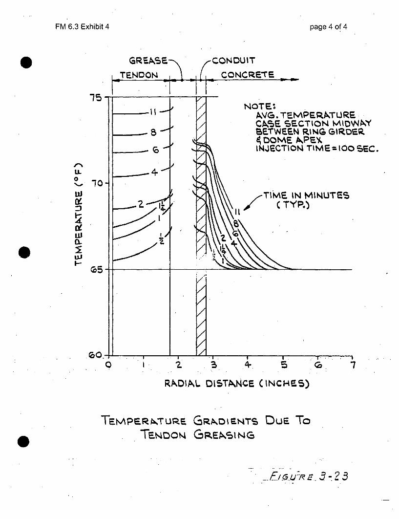
FM 6.3 Exhibit 4 page 4 of 4
S CONDUIT
CONCRETEETENDON
15NOTE.%
AVG. TEMPE~kTURSCA5F SECTION MMV4WYBE.TWEE.N RING GIRDER4 0Ot-E AkPE'V.INJECTION TIME= IOOSEC:.
IL0
N-.
ui
0i
ELI
10YTIME IN MINUTES
I/'** C TY P.)
0
0 G 7
RkIA~L DISTkNCE. (INCHES5)
TEmpep,ý.Tuze. GRAzDiENTS.TENDoNi GREksiNcz
D uE To
0
F-u R/u~e s -. 3

*o Fl46-.3-E-ibiA CRYSTA,. PIVER 1'1I- !,0. 3 page 1 of 3• .. ~ ~ N,% . - % "" " .-,,Fr•II. ACi'o R BUI I I !'!:C P ' )' -S r S 1 Gc SYSTEM
SIL:;TIHCATION NV*3ER /C U 2. CUT LENGTH /•. -
SHOP WA,•X-E. ID: PC /Z / CR _ ____ FIELD WASHER ID: PC /L_0 CR- Z3Z.
I. GAI/QA vendor inspecticn cover letter nuzcr-FPC g f5? DATE __Z__f_/7_ "
2. Da:e tendon re:eive', cn-site _,/6--7Y FMIR Nunber e r-3
3. Date installed in cenrd'uit 7- -3-7-yf Installation NCR's____________
Wires removed 0 Wires replaced C Total Ineffective wires 0
4. Date buttcnheaded 3 -7YButtonheading NCR's_______________
Bad wires 0 Accept. Reheads - * .Total Ineffective'wires 0
5. Date stressed /9-/!1 -79 ]tressing NCR's
Date restressed Restressing NCR's
SHOP END FIELD END TOTAL
Elonga'tioni (1500 psi to 80-,. ult.)-Pred./Act. WI2#i ,Z!f' /,Z &'0 /.Z
tft-Off Pressure - Predicted/Actual N/0A / 7 OS'O#$ U //A
Shim Thickness/80% Ultimate Pressure / 7"/ CO . J N/A
Unseated/Broken Wires 0 Total effective wires after stressing / 3
6. Dae Bulk-filled /P-Z3-7y/ Bulk-Filling NCR's
Time since installation- ý' Inlet Pressure I/ ~~ Outlet Temp. L 0
Date end caps refilled: Shop Field
7. Data compiled by '-• e 2t" Organization ____.
Da t e 2 _ _ _ __7_ _
8. Additional Co.-,znents:
.. 17 715

40 --
page 2 of 3CRYSVLU' PIVU 1" 1 NO. 3
REACrOP. Pf; L MP, FV FI'KSS1 SYSTEM
i ID--:;rICAT1O:, .,=.Z3R CUT LENGTH -
SHOP I,4A'E- ID: PC /Z/ CR ___7 FIELD WA_:ZR ID: PC /Z0 CR 17(o
1. GAI/QX vendor inspecticn cover letter number-FPC 0 _ __ __ DATE 2/2s-/7Y
2. Date tcndo reseivce- ern-site 1-16 - '7-*/ RMR N,= ber 3G& 03 &
3. Date installed in conduit 7 - 3- 7-Y Installation NCR's _
Wires rcmoved W Wires replaced 0 Total Ineffective wires 0
4. Date buttcnheaded 7- Z Y 7- 1 Buttonheadin; LNCR's
Bad wires 7 Accept. Reheads d-1 Total Ineffectivewires .3
5. Date stressed 9' 2 7 - 7Y Stressing NCR's
Date restressed Restressing NCR's
SHOP ELND FIELD END TOTAL
Elongation (1500 psi to 807.' ult.)-Pred./Act. /Z70// , N/A ./Z• ;1k/ /Z
tft-Off Pressure - Predicted/Actual . 8D /7 I / " I N/A
Shim Thickness/80% Ultimate Pressure /34 /7770 / N/A
Unseated/Broken Wires 0 Total effective wires after stressing /1 3
6. Date Bulk-filled /40- 2 3 -7 Bulk-Filling NCR's
Time since installation.3%r -'0jd5 Inlet Pressure //P • Outlet Temp. /22
Date end caps refilled: Shop Field
7. Data compiled by Organization
Pa te -'11
8. Additional Co•.--ents:
q07 71A

• •'-.: = •page 3 of 3.*4W,5 CRY. T[A P7V I R 11'1 9,. 3
,, a. . Ri:ACLoR i1UIL1I*:' PW.:;ý ,S:, , N SYSIEM
ID2'rIFICATlo:4 :;u:SER /Z k' l/ CUT LENGTH C '- 7
SHop W.ASPR ID: PC /Z/ CR S'_7 FIELD WAS-iER ID" PC /c.P CR (.a7
1. GAI/QA vendor inspecticn cover letter n,..zber-FC _ ___" __DATE 2/1Zr/ _/,y
2. Date tendon receive-2 cn-site // M('1 R'IR Number 3•O.3
3. Date installed in conduit 7 J - Installation NCR's
Wires removed 0 Wires replaced 0 Total Ineffective wires
4. Date buttenheaded - Z7 - 7y? Buttonheading NCR's
Bad wires _ Accept. Reheads 4" Total Ineffective wires /
5. Date stressed / Y /'- 7y! Stressing NCR's
Date restressed Restressing NCR's
SHOP END FIELD E'ND TOTAL
Elongation (1500 psi to 80. ult.)-Pred./Act. /Z/ / 14 A//A, I /ZA06 ,/2/"'sft-Off Pressure - Predicted/Actual 67•. /740D f "'I NIA
Shim Thickness/80% Ultinate Pressure 1I / /7"7 Z -j " N/A
Unseated/Broken Wires Total effective wires after stressing / Z
6. Date Bulk-filled 3-30 7• Bulk-Filling NCR's
Time since installation6 oW0,er,• j Inlet Pressure / e4 4 7" Outlet Temp. /27
Date end caps refilled: Shop Field
7. Data compiled by Organizational__o_.-____u__s_:
Date 7?
8. Additional Co-.zi-enrs:
7T7__71• .... . -.

raRA et' ^ r--.--L. ,' -_nAne 4 () C 11F lVi 'J.' iLAI U#JVE 1.1 pri qnen nl- S i ity c6h6
,P.4
88
.,Drying Shrinka66,and Creep
'0
*20 ~
'4
IC C-
pe 0 fr'imsOnes and gabbrost0 lotgraavels, and quartzjite. Si'ncethe t ItXi 6 p6
.,be estimated from, the weigh.. tevfficient f thermo r Sanston.cent aggregate in the concrete mi erage of the COminent a.sumng, concr70 eto aeaggregate X!te iture, h; . . vau~es ofasui the C•flcrete(both coarse fieageglk fromthed Sam coeffi'umrn9 7 fo 0prýSvarious rocktpes arear.. . 'clseto the .Xerimetal-o - cefficietefr,
in Fig. 4-9. The dat- -: . Peaggregate frdatami nh "Fig .. .i9i oof thermal coefficients reportedi the P6ub-se selto th", I.e, Per-onl tesuted in oistconditions, w hich is representative o f the Cond 'tio -etoftte te. Com-
ncrete~~te innhemooistin~pared to concrete in the moist state, thecorre sndpical mass concrete. Com-would show a slightly higher coeffici entL, P rob a a rgonceteof-the aireaeried state. ,• , v ,uaty s~areslt f increase inL density,
z 200
4a.
XZ108
o ,, l4'ls i 1 i~ e4 Ifune-fh "..00 -z I-
w
wiC-6-,
Figure 4-8 Effect of cementand pozzolan contents on-temperature rise in concrete.(From R. W. Carlson et al.,
_0 Al't D-I I-1 7A Xd,.
. - .- . - "7 , 19 7 9 .)'TIME -DAYS
The useof'a low cemient content, aniASTM Type llportland cement instead of Type I,"and a parial sbstitut ion of the portland cement-by a pozzolan, are effective means by
.which the adiabatic, temperature rise in mass concrete can be significantly reduced.
while maintaining a satisfactory level of strength, In this way the temperature risein concrete cahrbte limiitedý,to 'about-16C. -A ,partial substitution of the cement by30v6lumneercent f pozzolan ca further reduce the temperature rise to a mere 13 'C.
Precoolingof fresh concrete isanothercommonly used method of controllingthe subsequnt temperature drop. Often, chilled aggregates and ice shavings arespecified for making mass concrete mixtures in- which -temperature of. fresh concreteis limited tolO0C or less. Dunng theiemixing operation the latent heat needed for-fusion of ic:iiith~drawnf.r6mother materialsiofthe concrete mixture, providing.
'~ ~' Figur e 4- Infuneo the ce.i"4 5 .6 7 , : ;9 li- Io 2, I aggiegate type:on itne . e6t-•COEFFICIENT OF THERMAL EXPANSION' -ctient. oftherifial expansi•n•ofOF AGGREGATE (MICROS TRAIN P.EIR *C) .:co .ncrete,;..' *. '. :
Since the coefficient'of thermal e'xpansi'n. of concreote ifiir related-tothe cefficient -
of expansion of the- aggregate present',.in mass concrete the.selectioni of an ggregate with*
:a lower coefficiehi- provideý atik ah&er aproach toward loweii gth e ther ra iih.
+,
Seconowical7l f• t h coefficientf thermal expansion, when it is:become a ' sib;e-and 't cnlogically acceptable may under certain conditionscritictalfactor for crack:" prevention in. m -ass concrete. This is ,bec ,se thethermal shrin esti:-a is .ds o . - .
P. terminrnedhbl h by the-and, the linarcoefficint by the magritude of:the'temperature droptrolled prima b O ..... i .... ,i, P s6on of o ncrete, t .. .... in turn, is con-,oby~he linear coefficient o tr expansio othe aggregate. "-
The reported vuiOfte t hma-x ofhe'Portlan 'cemtientpastes of t •lier •ce n thermal expansion fo resaturtedof rying waI•terc•iemet ratiosfor mortars Icntaintin 1:6 -
cement/n~~turalsXl, snndfrccrete mixtures of different--ýcompstof ra phe rm '- 1 , a d to i j 6Per 'C , respe-ctively 'T he co ef i i n of -
-ute n n a.M M Ypn ~ o o f c o m nl d ro c k s 'a n d rn in e r a ls a r s 6'o d o t 5 ( <
DRYING- SHRINKAdt AND CREEP
fctsfrom- dy ing shrnkage and creep sirains in cqncrete areSnot-the snerally,mthe(stress eufer ct. of restr the. fornier is stress- induig-hil-• '•:,-• .. ... er ,nditionsof iestriutO ...t .,. : ., :.
. ' " • n o t th e .,S a m e ' ( i e . ,- .. o e c o d t ° m . . • e s m it s ~ d e s ~j r a b le t o d a c u s s -... ,;: . .. ... ..:. . : *: •• v ',,fora Vatlaet)'o rear,ýOn it* f<- theS,•*<
the latter is stress, rjl.ving)-. Rowever- f a are .*n ea S itpis dee o r pmqots ...
. -'b o th p h e n o m en a to g eth er : Irst • ,b dryi g th st a i - time5 F ' tjbo thudrrý, o-,rg ein a ,r tVeryseeennd, t se• t•h, -.... . ...
--- same source the hydrated ceme ,. ae apsoe-nflue-ce the crepr
similar; third, the factors that influence the dryingF sh•ri•ei ta of efach, 00 tOn • fourth, in concrete the.i. crostrai a re.; :a n d g e e a lly in -th e s a m e w a y ;. "; : , L . , n s f ctu ra l-d e s ign ; a n ~d fifth <b o th a e
- 1"00.x lO6-ie!anrgeend cannot be ignored int W11 lde',. < n " bo
partia , rew i,'rib e. . .- ~-,--- -~ - ~ -- __________

FM 6.3 Exhibit 7 page 1 of 1
Coefficient of Thermal Expansion(CTE) of concrete
From P. Kumar Mehta, "Concrete: Structure, Properties, andMaterials" (1986), pages 88 and 89.
* The coefficient of thermal expansion (CTE) of concrete depends onthe CTE of the coarse aggregates;* It varies in the range 6 to 12 xl0-6 /C;
* For limestone coarse aggregates, the CTE is close to 6 x 10⁻⁶ /°C;
This compares with steel CTE close to 6 x 10⁻⁶ /°C.
1

Thermal Conducthvity - k - (W.mK)
u6 iTit 8 emperatp 1 of 325 125 225
Acetone 0.16
Acrylic 0.2
Air 0.024
Alcohol 0.17
Aluminum 250 255 250
Aluminum Oxide 30
Ammonia 0.022
Antimony 18.5Argon 0.016
Asbestos-cement board 0.744Asbestos-cement sheets 0.166
Asbestos-cement 2.07
Asbestos, loosely packed 0.15
Asbestos mill board 0.14
Asphalt 0.75
Balsa 0.048
Bitumen 0.17 TBenzene 0.16 .Beryllium 218
Brass 109
Brick dense 1.31
Brick work 0.69
Cadmium 92
Carbon 1.7
Carbon dioxide 0.0146
Cement, portland 0.29
Chalk 0.09
Chrome Nickel Steel (18% Cr, 16.38 % Ni)
1-,A1 +___,

rnmon Materials nmonMateialshttp://www.engineeringtoolbox.com/the)
FM 6.3 Exhibit 8 page 2 of 3
L = Concrete, stone 1 1.7 1 1 1uonstantan
Copper 401 400 398
Conan (ceramic filled) 1.06
Corkboard 0.043
Cork, regranulated 0.044
Cork 0.07
Cotton 0.03
Carbon Steel 54 51 47
Cotton Wool insulation 0.029
Diatomaceous earth (Sil-o-cel) 0.06
Earth, dry 1.5
Ether 0.14
Epoxy 0.35
Felt insulation 0.04
Fiberglass 0.04
Fiber insulating board 0.048
Fiber hardboard. 0.2
Fireclay brick 5000C 1.4
Foam glass 0.045
Freon 12 0.073
Gasoline 0.15
Glass 1.05
Glass, Pearls, dry 0.18
Glass, Pearls, saturated 0.76
Glass, window 0.96
Glass, wool Insulation 0.04
Glycerol 0.28
Gold 310 312 310
Granite 1.7- 4.0
Gypsum or plaster board 0.17
Hairfelt 0.05
Hardboard high density 0.15
Hardwoods (oak, maple..) 0.16
Helium 0.142
Hydrogen 0.168
Ice (0°C, 32 0F) 2.18
Insulation materials 0.035 -0.16
Iridium 147
Iron 80 68 60
Iron, wrought 59
Iron, cast 55
Kapok insulation 0.034
Kerosene 0.15
Lead Pb 35
Leather, dry 0.14
Limestone 1.26- 1.33
Magnesia insulation (85%) 0.07
Magnesite 4.15
Magnesium 156
Marble 2.08 -2.94
Mercury 8

ntmon Materials http://www.engineeringtoolbox.com/thei
FM 6.3 Exhibit 8 page 3 of 3
Molybdenum 138
Monel 26
Nickel 91
Nitrogen 0.024
Nylon 6 0.25
Oil, machine lubricating SAE 50 0.15
Olive oil 0.17
Oxygen 0.024
Paper 0.05
Paraffin Wax 0.25
Pedite, atmospheric pressure 0.031
Periite, vacuum "0.00137
Plaster, gypsum 0.48
Plaster, metal lath 0.47
Plaster, wood lath 0.28
Plastics, foamed (insulation 0.03materials)
Plastics, solid
Platinum 70 71 72
Plywood 0.13
Polyethylene HD 0.42 - 0.51
Polypropylene 0.1 -0.22
Polystyrene expanded 0.03
Porcelain 1.5
PTFE 0.25
PVC 0.19
Pyrex glass 1.005
Quartz mineral 3
Rock, solid 2 - 7
Rock, porous volcanic (Tuff) 0.5 - 2.5
Rock Wool insulation 0.045
Sand, dry 0.15-0.25
Sand, moist 0.25-2
Sand, saturated 2-4
Sandstone 1.7
Sawdust 0.08
Silica aerogel 0.02
Silicone oil 0.1
Silver 429
Snow (temp < 0°C) 0.05 -0.25
Sodium 84
Softwoods (fir, pine ..) 0.12
Soil, with organic matter 0.15 -2
Soil, saturated 0.6-4
..... .Steel, Carbon 1 .% J: .... .. . . .. . . . .......... -IStainless Steel 16Straw insulation 0.09
17ffi 19
Styrofoam 0.033-]_____ ___
Tin Sn 67Zinc Zn 116 1
Urethane foam
Vermiculite
Vinyl ester
0.02 14-
0.058
0.25

FM 6.3 Exhibit 9I /'ýJ, I page 1of4
< t - I 4 -frt - - T
72~F 7- 72 ,
/5til 5fC1% ;.1 ri{ (X4, e.a~ite) ot
a 0/
•I,)(- /o ý c. t fli( 4T a'. x,,f e -,'-f 4-1 yvew
veloct> 1/;- /. 4/ ýr7/
-~~~ - /-. q- f -~
I wi-ame -V •-/t t.. - •o) •, •, (••-3,5 ý=•n,c!S•t* tt13f
>;--5,Cp.LoS '"j,'iq-A
"7"cMAt 2 tcoornemv(!5 ofbJdAýh J14
VO./~ CAcl$ Secrlle Aý:.0, 5p
sfevO Cf p a~ Ct e l0 2 7 8f& 7
Tu-r, W&kk,T e. h iJ C) &I ýý 6 -4endopj,
S's
V4 fieAM ýd4 1 oe
wV /crLAI" Bk :6 0P-
-T,/-72F

FM • Exhibik9ýglof 4r
f/
~ d~Pool jfotjVdm~e VI -t L/djoe 2-D,0, 3 32-
rt 53
.. . .... ......
i) ~g/</
i
5eced )
17,e t-N<IJ)d" er
ZN T2-3 -_ (oo3 92 ) ~(/•~c'372'-'zJ - OO
72- 7.
Cc~y' 4ui.e{ 1 ~ e ~t~
A w44b~v1k
- If-I /~ ~
/6o-- Ooý3(?-ZX (/oc0) - 1/6,2 --
41a b -( rh eQyM4 S~4A.3evo d

FM 6.3 Exhibit 9 page 3 of 4
355 4 (/4')t
F 77 340
b8&-Q71k 1 /X3V
Li
r-v-5 's cooJ'e-6 tv;-'k. F~1gu 3-So6v~gk, 3r de-mot's tAm4td c--bove 7s bc4 e d v~ cý. 5e-
~ -re,'~c~& -{Ass 6nc~4~s tACA 54r~t efjfecfý54o~cb
blwA5"nSetlt ýf~fec.± ce-1'&4cied) - -1the effec( ok1 -fte"nid 5't/x~s
/4 3 -ji oA //L ýt f4 /cp- S0c
v d iAAL4 b~cyd ý' 4k• "-aepa

FM 6.3 Exhibit 9 page 4 of 4
rhes"0 Ae4t veSee 'Yie+e ~2'4 A .e(/5/2Qf;4 •5 "4COYIho.. L1J a~- d ere c-ovsS'fe-nt c'A- m c a~tc, 0A- 5 AIC/
(O-YlC%6(OflS " e vte 3-23 ,P~Aofr~h S 1(1.{f /1,~,
A '4ie,4 -e6AW •ttus-s s ee))ý;e"e aY'1~A 5ZLOF~
a f +e mpeAcp-tuee ?AoJ~e , Tfle A~t4~4
2c•.i , 2 . • "• ' Iwe- ,d (ý 2,,o,(.-k- , Y-lq
i~-?~-rhe $-oje S neotA -ri- p~Qe s l~y~e~4e~
(\ '71 ( •. e ;t (7/ -f /,'v-t•r a
-t-eA m4 ~ ~ ~ s
S o.1 co-s4,oe', 4•, --. , ;
IAs TJlecte AeacLa ýS -tku e~icl of tv {,.; J4/f ea 5e
2~~~~~~6 0~ A3c jL5 i&- 1 re'
"C""2
c,/

FM 6.3 Exhibit 10 page 1 of 1
Supporting Document for Data Request #205 (Grease injection at 85 psi while tendon sleeves can handle
10 psi)
It was reported in the dome delamination report that tendon grease was injected at up to 85 psi. The
Requirement Outline for the tendon sleeves (RO-3040) identifies the ability of the sleeves to handle a
hydrostatic pressure of 10 psig without leaking water as a performance requirement. This appears to be
a discrepancy, especially considering that the hydrostatic pressure in the vertical tendon sleeves will
exceed 10 psig due to the column of grease that normally exists. This evaluation will determine if the
tendon sleeves could reasonably accommodate the reported injection pressure without failure.
The vertical tendons extend from elevation 80'-6" to 267'-6" per Prescon Drawings 5EX-003-P-03 and
5EX-003-P-40. The total elevation change is 187'.
The tendon grease is Visconorust 2090P-4. Per the MSDS, the specific gravity is 0.885. The density of
the grease is 0.885 * 62.4 lb/ft 3 = 55.2 lb/ft3. The pressure at the bottom of the tendon sleeve is
therefore 55.2 lb/ft3 * 1 ft2/144 in2 = 0.384 psi per foot of elevation of grease. For a full tendon sleeve,
the pressure is 187 ft * 0.384 psi/ft = 72 psi.
The tendon sleeves are either a rigid or flexible type. From a pressure retaining standpoint, the thinner-
wall flexible sleeves are more limiting. From RO-3040, the flexible sleeves are 5-1/4" OD, minimum 22
gauge (0.028) corrugated galvanized steel. The equation for minimum wall thickness from USAS B31.1
can be used to determine the pressure capability of the sleeves:
P = [2*5*E*tm]/[DO-2*y*tm]
Where S = maximum allowable stress, 10,600 psi
E = joint efficiency, 0.82
tm = minimum wall thickness, 0.028 in
Do = outside diameter, 5.25 in
y = constant, 0.4 for temperatures below 900F
P = [2*10,600*0.8*0.028]/[5.25-2*0.4*0.028]
P = 91 psig internal pressure
The above calculation shows that the tendon sleeves could handle the reported injection pressure as
well as the normal hydrostatic pressure, even when considering conservative material and joint
efficiency properties. When considering more realistic properties and the safety factor inherent in the
allowable stress value, there exists considerable margin in the sleeve material.
Prepared by Craig Miller 1/09/10
1 Tendon sleeve material is unknown. The minimum allowable stress for non-butt welded carbon steel, as given inTable A-1 of B31.1, is 10,600 psi at 200F.2 B31.1 lists joint efficiency from 0.80 to 1.0 for various longitudinal welds (excluding furnace butt welds, which
would not be practical for corrugated pipes). The lowest value of 0.80 is selected for conservatism.

FM 6.3 Exhibit 12 page 1 of 2
CALCULATION SHEET
ROUGH ESTIMATE OF THE IMPACTOF TENDON GREASE INJECTION ON
CONCRETE TENSILE STRESSES
A. DISCUSSION
After installation and tensioning of the containment building tendons, hotgrease is injected at moderate pressure to seal the void in the tendon conduit.The injection temperature was typically about 140 F with a limit of 200 F, andpressure was typically about 40 psi with a limit of 150 psi. Both temperatureand pressure have the potential for producing a tensile load on the concretesurrounding the tendon conduit. This calculation sheet places an upper limiton that potential impact.
B. REFERENCED PARAMETERS
o Tendon strand diameter: 7mmo # of strands pertendon: 163o Conduit OD: 5.25"o Conduit wall thickness: 1/16"o Max. grease temperature: 200 Fo Max. grease pressure: 150 psio Assumed linear coefficient of thermal expansion for steel and
concrete: 7 E-6 /Fo Assumed pressure coefficient for steel and concrete: 30 E6 psio Assumed concrete ambient temperature: 70 Fo Containment wall thickness: 42 ino Conduit/ft = 157 ft/ 94 tendons = 0.60 tendons/ft vertical
C. CONDUIT RADIAL EXPANSION DUE TO PRESSURE
dR/R = 1/(30 E 6 psi) * 150 psi = 0.000005
D. CONDUIT RADIAL EXPANSION DUE TO TEMPERATURE
dR/R = 7 E-6 /F *(200 F - 70 F) = 0.0009
Cross-sectional area of one strand is 0.06 sq inTotal cross-sectional area of 163 strands is 9.7 sq inTotal cross-sectional area of conduit is 21.6 sq inGrease fraction is 45%

FM 6.3 Exhibit 12 page 2 of 2
E. CONCRETE TENSILE STRESS DUE TO EXPANDED CONDUIT
Conduit expansion pressure is 0.0009 * 30 E6 psi = 27 ksiExpansion force per linear inch of conduit is 27 ksi * 1/16 in = 1700 lbf/in
Average tensile pressure on concrete is 0.60 conduit/ft * 1 ft/ 12 in *1700lbf/in = 85 psi
F. CONCLUSIONS
o Radial expansion due to pressure is negligible relative to temperatureo Radial expansion due to temperature (assuming conduit goes immediately
to 200F) produces an average concrete tensile stress of 85 psio The thermal expansion impact is actually significantly less than estimated
here since actual outlet temperatures were about 140 F instead of the limitof 200 F and the heat loss that occurredby 45% volume greasesurrounded by 55% volume steel strands. Actual stress is more like 20psi.
By Ray Waldo, PII team

FM 6.3 Exhibit 13
SystemsCalc. Sub-TypePriority CodeQuality Class
page 1 of 5 I.,
MX
3Safety-Related
NUCLEAR GENERATION GROUP
ANALYSIS I CALCULATION
S09-0044(Calculation #)
Predicted Tendon Elongations for Restoration of SGR Access Opening(Title including structures, systems,:components)
E] BNP UNIT
0 CR3 EIHNP ElRNP LINES REALL
APPROVAL E Electronically ApprovedRev # Prepared By Reviewed By Supervisor
rm- Name Name
Amir Mold Chris Sward Chrs Sward
Date Date Date
q/)'I-/OcI 0_________ OR___14 __1_09
(For Vendor Calculations)
Vendor Sargent & Lundy LLC Vendor Document No.Project No. 11550-048
N/A
DateOwner's Review By

FM 6.3 Exhibit 13 page 2 of 5
Calculation No. S09-0044 Revision 0Attachment
Page 1
1.0 Purpose
The purpose of this calculation is to determine the theoretical (predicted) elongation.of containment post-tensioning tendons that are either to be replaced or re-stresseddue to Steam Generator Replacement (SGR). The elongation to be predicted isthe immediate elongation that will occur during stressing from an initial force thatwill remove all slack to the maximum force at 80% of ultimate capacity.
A description of the opening in the containment shell, as well'as the tendons to beremoved or de-tensioned for the SGR, is described in calculations S06-0002 andS06-0005 (Refs. 4 and 5).

FM 6.3 Exhibit 13 page 3 of 5
Calculation No. S09-0044 Revision 0Attachment
Page 2
2.0 References
1) DBD11, Design Basis Document for the Containment, Rev. 6.
2) 5EX7-003 P-10A, Rev. 1, Horizontal Tendon Detail, (Prescon).
3) 5EX7-003 A-07, Rev. 2, Anchor Detail at Buttress, (Prescon).
4) Calculation No. S06-0002, Rev. 1, "Containment Shell Analysis for SteamGenerator Replacement - Design Criteria".
5) Calculation No. S06-0005, Rev. 1, "Containment Shell Analysis for SteamGenerator Replacement - Shell Evaluation During Replacement Activities".
6) 5EX7-003 P-2, Rev. 3, Vertical Tendon Placement, (Prescon).
7) 5EX7-003 P-3, Rev. 3, Vertical Tendon Placement, (Prescon).
8) 5EX7-003 P-4, Rev. 3, Vertical Tendon Placement, (Prescon).
9) 5EX7-003 P-15, Rev. 0, Vertical Tendon Placement, (Prescon).
10) 5EX7-003 P-16, Rev. 1, Vertical Tendon Placement, (Prescon).
11) 5EX7-003 P-17, Rev. 0, Vertical Tendon Placement, (Prescon).
12) 5EX7-003 P-33, Rev. 0, Vertical Tendon Placement, (Prescon).
13) 5EX7-003 P-34, Rev. 0, Vertical Tendon Placement, (Prescon).
14) 5EX7-003 P-35, Rev. 0, Vertical Tendon Placement, (Prescon).
15) 5EX7-003 P-40, Rev. 2, Vertical Tendon Placement, (Prescon).
16) 5EX7-003 P-41, Rev. 4, Vertical Tendon Placement, (Prescon).
17) 5EX7-003 P-21, Rev. 2, Hoop Tendon Placement, (Prescon).
18) 5EX7-003 P-22, Rev. 1, Hoop Tendon Placement, (Prescon).
19) 5EX7-003 P-23, Rev. 1, Hoop Tendon Placement, (Prescon).
20) 5EX7-003 P-27, Rev. 1, Hoop Tendon Placement, (Prescon).
21) 5EX7-003 P-28, Rev. 1, Hoop Tendon Placement, (Prescon).
22) 5EX7-003 P-29, Rev. 0, Hoop Tendon Placement, (Prescon).
23) ACI 318-63, "Building Code Requirements for Structural Concrete".
F - 24) EC 63016, Rev. 5, "Containment Cooling".

FM 6.3 Exhibit 13 page 4 of 5
Calculation No. S09-0044 Revision 0Attachment
Page 3
3.0 Design Inputs
The following design inputs are used in this calculation:
" Tendon properties and design parameters from DBD1 1 (Ref. 1):
Curvature friction coefficient, /t,=0.16Wobble coefficient, K=.0003Number of tendon wires, n,=163Effective area of tendons, At=9.723 in2
Tendon ultimate stress, oult=240 ksi
" Modulus of elasticity for carbon steel; E=29000 ksie Hoop and Vertical tendon layout from Prescon Dwgs. Refs. 2 and 3" Vertical tendon profile geometry from Prescon Dwgs. Refs. 6-16" Hnn~p t•-ndnn ,nrnfil. np~nmp~tr frnm Prt_.,nnn 1nwq- Rpfs 17-22
" The initial tendon stress to remove slack to be 360 kips, from EC 63016 (Ref.24).
4.0 Assumptions
There are no unverified assumptions in this evaluation.

FM 6.3 Exhibit 13 Ca~cftrJ48f 19-0044
Rev. 0
Tendon 23V01
E= 29000 ksi
Ayire= 0.05965 sq in
0.16
K= 0.0003
r= 67.28 ft
n 163
At= 9.72 sq in
Modulus of elasticity of steel wires
Area of pre-stressing tendon wire (Area of 163 wire tendon=9.723 in 2 , per Pg. 6, DBD11, Ref. 1)
Curvature friction coefficient, per Pg. 27, DBD1 1 (Ref. 1)
Wobble coefficient, per Pg. 27, Ref. 1
Radius of vertical tendons about center of containment shell, per Prescon Dwg. P10-A (Ref. 2).
Number of effective wires, per Pg. 6, Ref. 1 and Att. 1
Effective area of tendon
T= 360 kips Initial force in tendon to remove slack
Tf= 1867 Ikips 80% of ultimate tendon force (tendon ultimate stress=240 ksi, per Pg. 5, Ref. 1)
1507 kips Net force applied to tendon
Point Elevation Azimuth y A0 c d R B EB AL L Tx Tave 6
1 268.00 117.58 1507.00
1A 250.00 117.58 18.00 0.00 0.00 18.00 0 0.00 0.00 18.00 18.00 1498.88 1502.94 1.15
1B 242.54 118.17 7.46 0.58 0.68 7.49 41 0.18 0.18 7.51 25.51 1452.35 1475.62 0.47
1C 235.03 118.75 7.51 0.58 0.69 7.54 41 0.18 0.37 7.55 33.05 1407.02 1429.68 0.46
2 79.67 118.75 155.36 0.00 0.00 155.36 0 0.00 0.37 155.36 188.41 1342.94 1374.98 9.09
RI
1lB'P
'Ci
Predicted Elongation:I 11.17 in
Total Tendon Length= 188.41 ft6 nf= 12.08 iny
A°cdRB
EB
AL
LTx
Tave
6
6 jnf
Vertical distance between points i and j (ft)
Circumferential change from point i to j (degrees)Cicumferential distance between points i and j (ft)
Absolute distance between points i and j (d2=c2 +y2 ), (ft)Radius of curvature of tendon between points i and j (ft)Angular change between points i and j (radians)
Total angular change from tensioning end to point j (radians)
Length of tendon between points i and j (ft)
Total length of tendon from tensioning end to point j (ft)Force in tendon at point j (kips)
Average force in tendon segment between points i and j (kips)
Elongation of tendon segment between points i and j (in)
Predicted elongation of tendon assuming no friction loss 6nf=To*L 2/(E*At)
2 *
Tendon Profile Circumferential Angular ChangeOffset

FM 6.3 Exhibit 14
Calculation Wire Elongation
Young's Modulus, E
Guaranteed UTS
Wire Diameter
Wire Area
Force per wire
Wire length
Elongation, A=FL/AE
Correction for 360 kips
Tendon force 80% GUTS
Reduced tendon force
Reduced percentage
Reduced elongation
page 1 of 1
2.90E+07240
0.2760.059611,4432,256
14.94
1,865,2421,505,242
19.30%
12.05
psiksiin
inA2psi
inin
(7 mm)
(80% x 240 ksi x 0.0596 inA2)
(188 ft for vertical tendons)
lbs (11,443 psi x 163 wires)
lbs (1,865 kips - 360 kips)(1,865 - 1,505) kips / 1,865 kips
in (14.94 * (1 - 0.193))

FM 6.3 Exhibit 15 page I of 13
Grease losses from tendon sleeves
25.00
20.00
25.00
20.00
15.00
10.00
15.00 r i.
lO.OO 4-
5.00 4- 1 5.00
7ý71w-0.00 . 0.00
surv 4 surv 5 surv 6 surv 7 surv 8
Grease Losses (gal) (left axis) --I-Std Dev (right axis)
Average and standard deviation of grease losses for each surveillance
2/21/2010 1

FM 6.3 Exhibit 15 page 2 of 13
GREASE REMOVAL AND REPLACEMENT
TABLE 4
Crystal RiverUnit 3
TENDON END GREASE GREASE NET DIFFERENCE :NUMBER DESIGNATION REMOVED REPLACED
-(gals.) (__als.)
12V1 Field + Shop 29.9 34.0 4.1 Gallons
34V4 Filed + Shop 12.9 17.9 5.0
56V2 Field + Shop 89.9 92.9 3.0
D105 Field + Shop 11.0 34.0 23.0
D212 Field + Shop 4.0 16.0 12.0
D328 Field + Shop 8.0 16.0 8.0
13H20 Field + Shop 2.0 21.1 19.1
13H40 Field + Shop 4.0 24.5 20.5
•H26 Field + Shop 2.0 21.1 19.1
51H274 Field + Shop 1.0 5.0 4.0
51H41 Field + Shop 2.0 25.6 23.6
64H19 Field + Shop 2.0 16.8 14.8
* Unsealed in error.
TP420Ads

FM 6.3 Exhibit 15 page
Crystal*River Unit 3 Post-Tensioning System:5th In-Service Tendon Surveillance Test Report: Revision 0
TABLE 5: SUMMARY OF GREASE REMOVAL AND REPLACEMENT
3 of 13
TENDON GREASE REMOVED GREASE REPLACED NET(GALLONS) (GALLONS) DIFFERENCE *
34V6
56V15
61V14
D215
D224
D231
35HI
42H1
46H21
46H28
46H29
46H30
46H47
62H8
30
96
64
38
40
02
02
04
3.5
07
04
04
02
71.5
116
82
51
51
51
22
22
19
19
22
17
24
22
41.5
20
18
32
13
11
20
20
15
15.5
15
13
20
20
* Acceptance Criteria: Net difference shall not exceed 4 gallons. Pleaserefer to the applicable NCR where it is noted that final evaluation anddisposition of acceptance criteria is deferred to Gilbert Commonwealth (to beaddressed in their engineering report).
17

FM 6.3 Exhibit 15 page 4 of 13
20TH YEAR SURVEILLANCE OF TIlEPOST-TENSIONING SYSTEM AT THECRYSTAL RIVER NUCLEAR PLANT
UNIT 3
FloridaPowerCORPORATION
TABLE XII: SUMMARY OF DATA SHEETS SQ 12.1GREASE LOSS Vs GREASE REPLACEMENT
TENDON GREASE REMOVED GREASE REPLACED DIFF. NET %
SHOP FIELD TOTAL SHOP FIELD TOTAL (GAL.) VOLUME(GAL.) (GAL.)
12VI 2.00 36.75 38.75 40.75 0.75 41.50 +2.75 143.46 1.91
23V2 0.75 9.75 10.50 11.50 0.00 11.50 +1.00 142.52 0.70
61V21 0.75 88.50 89.25 20.25 72.50 92.75 +3.50 144.03 2.43
43V04 0.50 0.00 0.50 7.50 0.00 7.50 +7.00 N/A N/A
D113 4.50 4.00 8.50 6.20 3.50 9.70 +1.20 115.11 1.04
-•D 115 4.50 4.50 9.00 7.00 4.00 11.00 +2.00 117.17 1.71
D212 6.50 4.00 10.50 20.00 4.50 24.50 +14.00 115.55 12.12.
D304 12.00 7.25 19.25 38.20 0.00 38.20 +18.95 103.68 18.300
D311 24.00 4.00 28.00 46.50 3.50 50.00 +22.00 115.12 19.10.
* SEE NCR No. FN604-018, 019, 020
t
45

FM 6.3 Exhibit 15
) 20Tll YEAR SURVEILLANCE OF THEPOST-TENSIONING SYSTEM AT THECRYSTAL RIVER NUCLEAR PLANT
K,/' UNIT 3
TABLE XII: SUMMARY OF DATA SHEETS SQ 12.1GREASE LOSS Vs GREASE REPLACEMENT
page 5 of 13
FloridaPowerCORPORATION
.1
V.'
TENDON GREASE REMOVED GREASE REPLACED DIFF. NET %
SHOP FIELD TOTAL SHOP FIELD TOTAL (GAL.) VOLUME
I (GAL.) I_ I_(GAL.)
42H18 3.75 2.00 5.75 5.25 5.25 10.50 +4.75 121.40 3.91
42H29 3.50 3.25 6.75 5.25 6.25 11.50 +4.75 121.48 3.91
42H30 3.00 3.00 6.00 7.00 7.00 14.00 +8.00 121.59 6.58.
42H31 2.50 3.00 5.50 5.25 5.75 11.00 +5.50 121.84 4.51
42H32 3.75 2.50 6.25 6.25 4.75 11.00 +4.75 121.36 3.90
421-133 3.00 3.00 6.00 6.25 4.75 11.00 +5.00 120.38 4.15
42H34 3.00 3.00 6.00 6.50 6.25 12.75 +6.75 121.99 5.53 *
42H35 3.25 4.50 7.75 4.90 5.30 10.20 +2.45 121.27 2.02
"-42H36 4.00 4.00 8.00 4.00 5.75 9.75 +1.75 121.62 1.44
42H37 4.50 4.50 9.00 6.20 5.00 11.20 +2.20 120.44 1.83
42H44 4.75 3.50 8.25 5.30 4.90 10.20 +1.95 121.08 1.61
51H25 * 3.50 3.50 7.00 8.00 4.50 12.50 +5.50 120.73 4.56
51H25 * 3.00 4.00 7.00 4.50 4.00 8.50 +1.50 120.73 1.24
51 H26 4.50 3.75 8.25 5.25 4.50 9.75 +1.50 121.43 1.24
51H27 3.50 3.25 6.75 5.30 5.70 11.00 +4.25 121.60 3.50
511H28 * 3.50 4.00 7.50 4.50 4.75 9.25 +1.75 120.46 1.45
51H28 ** 4.00 4.00 8.00 4.50 4.00 8.50 +0.50 120.46 0.42
53H2 4.50 4.00 8.50 5.75 6.25 12.00 +3.50 121.32 2.88
53H46 3.25 3.50 6.75 6.00 5.25 11.25 +5.25 121.60 4.32
621141 4.00 4.00 8.00 7.10 5.30 12.40 +4.40 •121.37 3.63
62H46 3.50 4.50 8.00 6.25 6.50 12.75 +4.75 121.11 3.92
51 H41 N/A 3.50 3.50 N/A 4.00 4.00 +0.50 N/A N/A
.4'I
I
GREASED 11/18/97GREASED 12/18/97
* SEE NCR No. FN604-021
46

FM 6.3 Exhibit 15 page 6 of 13
25TH! YEAR SURVEILLANCE OF TIHEPOST-TENSIONING SYSTEM AT THE Florida PowerCRYSTAL RIVER NUCLEAR PLANT A Progress Energy Company
UNIT 3
TABLE XI: SUMMARY OF DATA SIIEETS SQ 12.1GREASE LOSS Vs GREASE REPLACEMENT
TENDON GREASE REMOVED GREASE REPLACED DIFF. NET %
SHOP FIELD TOTAL SHOP FIELD TOTAL (GAL.) VOLUME(GAL.) (GAL.)
12V01 2.25 105.75 108.00 0.00 115.00 115.00 7.00 139.43 +5.02
12V02 3.00 0.00 3.00 3.50 0.00 3.50 0.50 139.78 +0.36
23V02 2.75 0.00 2.75 4.75 0.00 4.75 2.00 139.85 +1.43
45VI4 7.00 102.50 109.50 0.00 118.50 118.50 9.00 140.34 +6.41
61V08 7.00 102.75 109.75 0.00 112.50 112.50 2.75 139.78 +1.97
461121 3.25 3.25 6.50 3.50 4.00 7.50 1.00 119.96 +0.83
461129 1.75 1.75 3.50 3.50 2.50 6.00 2.50 119.73 +2.09
461130 1.75 1.50 3.25 4.50 2.25 6.75 3.50 119.73 +2.92
K , 461131 1.75 1.75 3.50 3.25 4.50 7.25 3.75 119.73 +3.13
461132 1.75 1.75 3.50 2.25 3.50 5.75 2.25 119.73 +1.88
461133 1.75 1.75 3.50 4.50 3.50 8.00 4.50 119.73 +3.76
461134 1.75 1.75 3.50 2.50 3.50 6.00 2.50 119.73 +2.09
461135 1.75 1.75 3.50 3.50 2.50 6.00 2.50 119.09 +2.10
461-136 2.25 1.00 3.25 2.50 4.50 7.00 3.75 119.25 +3.14
46H37 1.75 1.00 2.75 3.50 4.00 7.50 4.75 119.93 +3.96
461138 1.50 1.50 3.00 2.50 4.00 6.50 3.50 119.73 +2.92
461139 1.75 3.50 5.25 3.00 3.50 6.50 1.25 119.73 +1.04
56H116 2.50 2.00 4.50 3.00 3.50 6.50 2.00 119.53 +1.67
621102 2.25 2.50 4.75 4.50 5.25 9.75 5.00 119.33 +4.19
621-109 3.00 2.00 5.00 3.50 5.25 8.75 3.75 119.73 +3.13
621113 2.50 1.50 4.00 4.75 4.50 9.25 5.25 120.59 +4.53
D126 14.50 25.75 40.25 0.00 42.75 42.75 2.50 115.97 +2.16
D212 24.75 22.00 46.75 0.00 62.25 62.25 15.50 113.86 +13.73
D339 40.00 15.00 55.00 73.75 0.00 73.75 18.75 100.18 +18.72 *
ADDRESSED IN FN 730-007
ADDRESSED IN FN 750-006
40

IIIIIUIIII
FM 6.3 Exhibit 15 page 7 of 13
DOCUMENT NUMBER:
DOCUMENT TITLE
PROJECT TITLE:
CR-Ni 002-504 REVISION: 0 PAGE: 45
FINAL REPORT FOR THE 301" YEAR CONTAINMENT IWL INSPECTION
30*" YEAR TENDON SURVEILLANCE AT CRYSTAL RIVER DATE: 01124108 P Eu
10.2 TENDON CAP RESEALING AND GREASING
10.2.1 After completion of all inspections, the anchorage components were hand coated with cold grease toensure complete coverage. The caps were reinstalled with new gaskets and the results of the grease capreplacement were recorded on Data Sheet SQ 12.0 and are summarized in Tables 50 thru 55.
10.2.2 Upon acceptable cap replacement, the necessary amount of sheathing filler (grease) was added. All ofthe inspected tendons were refilled within the acceptable limits as stated in the PSC Procedure SQ12.1.The results of the grease replacement were recorded on Data Sheet SO 12.1 and are summarized inTables 56 thru 60.
10.2.2.1 The absolute difference between the amount of grease removed/lost and the amount of grease replacedin the subject tendon shall not exceed 10% of the net duct volume per PSC Procedure SQ 12.1. Notendon accepted above 10% of the net duct volume more than was lost, and all refills were acceptable.
I fl0S:J~l -- RBU ýE 'A
Z00ZW
0J a W LU
3 L) 0
JUZ(OR
us P.4c W00
4 0Ar0W
Po
Z ca
IA.
4fA V6
0 0
0 0
W0 Z 4WW a 00 4RX
&L0 C>.
UPOW0: !K3E -C 3
5 1 40 WWX W0
a.wD
IIIIIIII
TOP YES YES YES. YES YES NO YES12VTE
BOT YES YES YES YES YES NO YES
TOP YES YES YES YES YES NO YES46V20
BOT YES YES YES YES YES NO YES
TOP YES YES YES YES YES NO YES61 VO P
BOT YES YES YES YES YES NO YES
TOP YES YES YES YES YES NO YESGIV17
BOT YES YES YES YES YES NO YES
- AL 51-OEL o . GES A ELCMN
ZOot= t= & - , ,.-JZ4 ZJW tW 0 0i
I UI .&s Ya oES Y YES O IYS
w iW -( Z3Z
04. < J0I= 1 0 -K -,2 ! 9t 1BT3 YES YES YES YES YES NO YES
BT 5 YES YES YES YES YES NO YES
BT 1 YES YES YES YES YES NO YESD21 2
3T 3 YES YES YES YES YES NO YES
BT4 YES YES YES YES YES NO YESD238I IBT 6 YES YES YES YES YES NO YES

IIIII.IIIIIIIIIiIiII
FM 6.3 Exhibit 15 page 8 of 13
DOCUMENT NUMBER:
DOCUMENT TITLE:
PROJECT TITLE:
CR-N1002-504 REVISION: 0 PAGE: 46
FINAL REPORT FOR THE 30'm YEAR CONTAINMENT IWL INSPECTION
30TM YEAR TENDON SURVEILLANCE AT CRYSTAL RIVER DATE 01124108Emuy
- I - I - I ~ ! W P ~! ! - P - I -
"°"1 _•zz-- = ! = = = -=-w°4- . to---K..- - -5. go 0 ) Dosg 041- P - -1- w
BT 1 YES YES YES ' YES YES NO YES13H36
8T 3 YES YES YES YES YES NO YES
BT12 YES YES YES YES YES NO " YES
42H146BT 4 YES YES YES YES YES NO YES
BT 4 YES YES YES YES YES NO YES
461121BT 6 YES YES YES YES YES NO YES
BT 1 YES YES YES YES YES NO YES51 H34
BT 5 YES YES YES YES YES NO YES
BT 2 YES YES YES YES YES NO YES621H30
BT 3 YES YES YES YES YES NO YES
• .- ="-..
BT 1 YES YES YES YES YES NO YES13H33
T 43 YES YES YES YES YES NO YES
BT 1 YES YES YES YES YES NO YES13H34
BT3 YES YES YES YES YES NO YES
ST I YES YES YES YES YES NO YES13H35
BT 53 YES YES YES YES YES NO YES
BT 2 YES YES YES YES YES NO YES13H37
BT 3 YES YES YES YES YES NO YES
BT1 YES YES YES YES YES NO YES13Q338
ST 3 YES YES YES YES YES NO YES

UIIIIIUIIIIIIIIIIII
FM 6.3 Exhibit 15 page 9 of 13
DOCUMENT NUMBER: CR-N1002-504
DOCUMENT TITLE: FINAL REPORT
PROJECT TITLE: 30'" YEAR TEIN
REVISION: 0 PAGE: 47
FOR THE 30'm YEAR CONTAINMENT IWL INSPECTION
IDON SURVEILLANCE AT CRYSTAL RIVER DATE: 01/24/08
-Tk6L(Eqý4r 146f'liý1,04A-GtNýffi§ EJ- tVli 2.0 s:cýi5R'ý'ASlýICAýP,ýREFýLrAý.EMEkY
wI10zw
0 w4KC
w w0 V)
uo7-9z U,
on,
0 0IL
JWIn".15%IL
wul W
0 co
0 ZI Iqc
ill0O
0.
a.
BT 4 YES YES YES YES YES NO YES4GH19
8T 6 YES YES YES YES YES NO YES
ST 4 YES YES YES YES YES NO YES46H20
BT 6 YES YES YES YES YES NO YES
ST 4 YES YES YES YES YES NO YES46H22
BT 6 YES YES YES YES YES NO YES
BT 4 YES YES YES YES YES NO YES46H23
BT 6 YES YES YES YES YES NO YES
BT 4 YES YES YES YES YES NO YES
46H24BT 6 YES YES YES YES YES NO YES
-i I -l - w-
liei __ _ w
BT 2 YES YES YES YES YES NO YES62H$29
BT 6 YES YES YES YES YES NO YES
BT 2 YES YES YES YES YES NO YES62H31I
BT 6 YES YES YES YES YES NO YES
BT 2 YES YES YES YES YES NO YES62H32
BT 6 YES YES YES YES YES NO YES
BT12 YES YES YES YES YES NO YES62H33
BT 6 YES YES YES YES YES NO YES
BT 2 YES YES YES YES YES NO YES
6234 16 YES YES YES YES YES NO YES

IIIIIIIIIIII
IIIIIII
FM 6.3 Exhibit 15 page 10 of 13
DOCUMENT NUMBER; CR-Nl002-504 REVISION- 0 PAGE: 48 47
DOCUMENT TITLE FINAL REPORT FOR THE 30 YEAR CONTAINMENT IWL INSPECTION _
PROJECT TITLE: 3074 YEAR TENDON SURVEILLANCE AT CRYSTAL RIVER DATE: 01124108 EgS
(GALLONSI 1GALLONSITENDON END DIFF.(GAL) DUCT AVOLUME I % ACCEPT, AI 01FIFP(G L O s ... .. .. | ' O . ...
END TOTAL END TOTAL 1 %%7 %..p
TOP 2.5 012V01 78.5 82.19 369 14397 2.56 YES
BOT 76 82.19
TOP 3 04SV20 88 91.04 3.04 144.47 2.10 YES
BOT 85 9I.4
TOP 2.5 70861V08 55 5664 1.64 14,12 1.13 YES
BOT 52.5 49.56
TOP 2.5 161V17 BOT 596 98.5 1062 107.2 8.7 144.74 8.01 YES
RETAINED IN HARD COPY

IIIIIIIIIIIIIIIIIII
FM 6.3 Exhibit 15 page 11 of 13
D5 DOCUMENT NUMBER: CR-N.O02-504 REVISION: 0 PAGE: 49 __DOCUMENT TITLE: FINAL REPORT FOR THE 30TM YEAR CONTAINMENT IWL INSPECTIONPROJECT TITLE: 30"' YEAR TENDON SURVEILLANCE AT CRYSTAL RIVER OATE: 01124108 BMW
GREASE REMOVED GREASE REPLACED DUCTTENDON END (GALLONS) (GALLONS) DIFF VOLUME ACCEPT
END TOTAL END TOTAL (GAL.) DIFF.
BT 1 2.5 35413H36 5 7.08 2.08 121.67 1.70 YES
BT 3 2.5 354
BT 2 2-5 3.0942H46 55 5.74 0.24 122.57 0.19 YES
BT 4 3.0 2.85
BT 4 2.5 3.5446H21 5 7.08 2.08 12206 1070 YES
ST 6 2.5 3.54
BT 1 2.5 2,6551H34 5 6,19 1.19 120.88 0,98 YES
OT 5' 2.5 3.54
BT 2 2.5 3.5462H30 5ý 7.08 2.08 121.75 170 YES
BT 6 2.5 3.54
GREASE REMOVED GREASE LACED DUCTThNON ND(GAL NS) to !~ OIFF. DUC(GALONS)N EAUOND VOLUME AC7CEPT
END TOTAL END TOTAL (GAL) (GAL.) DFF.
BT 3 135 0D129 36,5 39.71 3-21 116.41 2.75 YES
BT 5 23 39.71
BT 1 2.5 0D212 20 23,78 3.78 115.99 3.25 YES
BT 3 17.5 23.78
BT 4 62.5 73.34D238 69.5 73.34 3.84 10259 3.74 YES
ST 6 7 0

IIIIIIIIIIIUIIIIIIU
FM 6.3 Exhibit 15 page 12 of 13
DOCUMENT NUMBER:
DOCUMENT TITLE:
PROJECT TITLE:
CR-N1002-504 REVISION: 0 PAGE: 50
FINAL REPORT FOR THE 30'" YEAR CONTAINMENT IW. INSPECTION L
30'" YEAR TENDON SURVEILLANCE AT CRYSTAL RIVER DATE: W0/24108 BMW
TENDON END (GALLONS) (GALLONS) DIFF. DUCT.... VOLUME DIFF. ACCEPT
END TOTAL END I TOTAL I twkt (GAL.)
BT 1 2 2.6513H33 4 53 1.3 121.57 1.06 YES
BT 3 2 2.65
BT 1 2 2.6513H34 4 5.3 1.3 121.25 1.07 YES
BT 3 2 2.65
BT 1 2 2.6513H35 4 5.3 1.3 121,77 1.06 YES
ST 3 2 2.65
ST 1 2 2.6513H37 4 5.3 1.3 12218 1.06 YES
BT 3 2 2.65
BT 1 2 2.6513H38 4 5.3 1.3 121.53 1.06 YES
BT 3 2 2.65
ST 4 2 2.21
46H19 4 4.86 0.86 121.25 0.70 YESBT 6 2 2.65
BT 4 2 2.6546H20 4 5.3 1.3 121.37 1.07 YES
BT 6 2 2.65
BT 4 2 2.6546H22 4 5.74 1.74 122.43 1.42 YES
BT 2 3.09
BT 4 2 26546H23 4 5.3 1.3 122.63 1.06 YES
BT 6 2 265
BT 4 2 2,6546H24 4 5.74 1.74 121.57 1.43 YES
BT 6 2 3.09 I

IIIIIIIII
FM 6.3 Exhibit 15 page 13 of 13
DOCUMENT NUMBER: CR-N1002-504 REVISION: 0 PAGE: 51
DOCUMENT TITLE: FINAL REPORT FOR THE 30'" YEAR CONTAINMENT IWtL INSPECTION
PROJECT TITLE: 30TH YEAR TENDON SURVEILLANCE AT CRYSTAL RIVER DATE: 01I24/08 Pgs
GREASE REMOVED GREASE REPLACED DUCTTENDON END (GALLONS) (GALLONS) DIFF. DUC %
7TEMOOM END L GAL.) VOLUME 01IFF. ACCEPTEND TOTAL END TOTAL (GAL.)
BT 2 2 2.6562H29 4 53 13 121.93 1.06 YES
BT 6 2 2.65
BT 2 2 2.6562H31 2 2.65 0.65 122.13 0.53 YES
BT 6 0 0
BT 2 2 2.6562H32 2 2.65 0.65 121.45 0.53 YES
BT 6 0 0
BT 2 2 2.6562H33 4.5 5.3 080 122.07 0.65 YES
BT 6 2.5 2.65
BT 2 2 2.6562H34 4 53 13 121.47 1.07 YES
BT 6 2 2.65
IIIIIIIIIU
S .If a large amount of grease islost during the inspection, thengrease must be replaced bypressure pumping it back intothe tendon duct.
Hh I AINtL IN tiAhiL t.AurT
ze * :e;5 0'


![WELCOME []€¦ · WELCOME Lubrication is the life blood of any machine. This is why greasing your machinery regularly is of utmost importance. Whether ... Bulkhead, Grease Anchor](https://img.dokumen.tips/doc/110x75/5ec0002546dae757453e9562/welcome-welcome-lubrication-is-the-life-blood-of-any-machine-this-is-why-greasing.jpg)