Embed Size (px)
Citation preview

62
CHAPTER 3 : Diversity Analysis in WiFi and WiMAX Systems
This chapter imparts information on wireless LAN and MAN systems that have
perceived the theoretical potentials of diversity techniques. While Wi-Fi essentially a
WLAN(Wireless Local Area Network) has monopolized the domain of short range
wireless broadband systems, WiMAX (Worldwide Interoperability for Microwave
Access), IEEE 802.16a, on the other hand has made radical inroads into the wireless
communications market of WMAN (Wireless Metropolitan Area Network) tagged as the
‘Revolutionary broadband wireless technology of the current era’ as it opens up a realm
of schemes for multiple antenna techniques comprising of Diversity Techniques, Smart
Antenna Systems (SAS) and Multiple Input Multiple Output (MIMO) Systems.
To reinforce the existing system and further enhance the measure of performance
in multipath fading scenario, Wi-Fi and WiMAX systems are intertwined with space
diversity techniques, implemented using Alamouti coding and introduced with
interleaving/scrambling techniques that benefit from time diversity. Diversity technique
plays a pivotal role in enhancing the quality of the wireless system’s operations, by
providing optimum performance on par with least distorted path amongst various
multipaths at any given point of time and thereby substantiating the fading effect caused
in corruptive communication channels. The probability of experiencing a fade in the
composite channel is then proportional to the probability that all the component channels
simultaneously experience a fade, which is an unlikely event. Thereby diversity, a key
technique that exploits the inherent multipath nature of wireless channels has been
deployed in our work to mitigate transmission errors. Multiple transmit and multiple

63
antennae have emerged as key enabling technologies for wireless transmission of
broadband data.
This analysis seeks to simulate the physical layer of Wi-Fi and WiMAX systems
with application of diversity schemes at the transmitter and receiver. 2X2 Alamouti
coding scheme has been implemented for exemplifying MIMO diversity and 2X1
Alamouti coding scheme for MISO diversity. Alamouti codes which have exhibited
remarkable results in flat fading channel and when coupled with OFDM structure have
been found to produce the same level of performance in multi path fading
environment[54,103,104]. Pertaining to Wi-Fi, IEEE 802.11b standard, the incorporation
of convolutional codes and DSSS has replaced the OFDM structure of WiMAX. The
study of BER of Wi-Fi and WiMAX systems, hosted with AWGN and Rayleigh
channels, have demonstrated the benefits of diversity reception. Studies have also been
undertaken to record the impact of modulation schemes like BPSK, Quadrature Phase
Shift Keying(QPSK) and 16-Quadrature Amplitude Modulation(QAM) on BER.
3.1. Combinational Diversity in Wi-Fi system
Wi-Fi, short for Wireless Fidelity is a wireless digital communication system that
operates in 2.4GHz ISM bandwidth. For LAN’s with coverage of only a few hundred
feet, the operating channel bandwidth is intended to be 25MHz. Any high-level protocol
can be used in a Wi-Fi network in a similar way as in an Ethernet network. The IEEE
802.11 standard is regarded as one of the earliest trailblazers in introducing bandwidths
of 1 to 2 Mbps. However, the original standard has undergone subsequent amendments to
optimize bandwidth that include the 802.11a, 802.11b and 802.11g standards, which are

64
called 802.11 physical standards, to ensure enhanced security and compatibility of the
components[105].
3.1.1. Technological aspects of Wi-Fi system
The physical layer defines the radio wave modulation and signaling
characteristics for data transmission. The data link layer defines the interface between
the machine's bus and the physical layer, in particular an access method similar to the one
used in the Ethernet standard and rules for communication between the stations of the
network. The 802.11 standard actually has three physical layers as shown in Table 3.1,
which define alternate modes of transmission[105].
Table 3.1. OSI model for 802.11 standards
Not all diversity schemes have been proposed in the IEEE standards and amendments to
WLAN, but the proposed CTD scheme emphasize on MIMO techniques and can be
categorized to facilitate their implementation in base band and/or in the RF section of
transceivers. The diversity schemes in the base band signal level at the physical layer
may be implemented with respect to time, code and space with bit interleaving, DSSS
and space time block codes respectively.
Data Link Layer (MAC)
Physical Layer (PHY)
802.2
802.11
DSSS FHSS Infrared

65
Since the data to be transmitted in the wireless network is scattered in various
dimensions, this compensates the impact of long term and short term fading due to the
multipath channels. Thus, enabling the receiver to reconstruct intelligent information
from the corrupted copy received from the transmitted signal. Despite the numerous
benefits of wireless network such as support for mobility, dynamic topology, device
portability, etc., the wireless technology is highly vulnerable to data security threats and
multipath interference. While the security concerns are handled in the upper layers of the
OSI model, multipath propagation a fundamental characteristic of wireless
communication is addressed in the physical layer.
This work investigates the improvement in SNR for the MIMO design with time
diversity, code diversity and space diversity in the physical layer of basic WLAN
standard. These diversity schemes are exploited with scrambling and bit interleaving,
spread spectrum technique and Space Time Block codes. The performance of simple 1 X
1 transceiver is compared with 1X2 and 2X2 modes of WiFi architecture.
3.1.2. System Description
The schematic diagram of transmitter model of Wi-Fi System is shown in Fig.3.1.
To increase the reliability of transmission in a noise effective channel, it is necessary to
decrease the frequency of error events and this vital role is played by channel coding.
Fig.3.1. Transmitter model of the Wi-Fi system
Channel Encoder
Interleaver
DSSS Transmitter
Space Time Encoder
From Mod

66
As per the standard, for the simulation of physical layer of Wi-Fi 802.11b,
convolutional codes are used as channel error control scheme and DSSS resulted with
code diversity. In addition to this, to encompass spatial and temporal diversity, STBC
encoder and interleaver are introduced to the existing standard. The schemes of CTD are
shown in italics in Table 3.2
Table 3.2. Technological aspects of WiFi 802.11b standard
Description Specification
Primary Application WLAN
Frequency Band 2.5 GHz ISM Band
Bandwidth 25 MHz
Modulation QPSK
FEC Convolutional Codes
Temporal Diversity Interleaver
Code Diversity DSSS
Space Diversity STBC coder
The convolutional codes are non-systematic binary codes and the encoder
operates on the incoming message bits in a sequentially manner[106]. The encoder of the

67
binary convolutional code with rate 1/n is considered as a finite state machine. It consists
of an M-stage shift register with connections to n modulo 2 adders and a multiplexer that
serializes the output to the adders. An L-bit message sequence produces a coded output
in sequence of length n (L+M) bits. The code rate is given by
R= L / n (L+M) bits/symbol 3.1
Another important parameter to consider is the constraint length (K) of the convolutional
encoder i.e. the number of shifts over which the message bit can influence the encoder
output. In an encoder with ‘M stage’ shift registers the memory of the encoder that
equals ‘m’ message bits and requires K=M+ 1 shifts, for a message bit to enter the shift
register and come out finally. The encoded data is fed to the interleaver, which in turn
scrambles the data in a non-contiguous manner, so that no adjacent symbols come from
the same code word. This is done to ensure that even if noise corrupts one bit of data, the
other bits can be used to retrieve the original data, enhancing the performance of the
system by mitigating the burst errors, which may occur when data travels in a corrupted
multipath environment. The IEEE 802.11b data is encoded using DSSS technology which
is the most widely recognized form of Spread Spectrum technique
As per the standards of IEEE 802.11b and QPSK is used to encode 2 bits of
information in the same space, this modulation has an added advantage of increasing the
data rate and thereby causing reduction in the available process gain. For a given PN code
rate, the process gain is reduced as the bandwidth which sets the process gain is halved
due to the bi-fold increase in information transfer. As a consequence the systems in a
spectrally quiet environment benefit from the possible increase in data transfer rate. As

68
the coverage range of Wi-Fi is limited to some hundreds of meters the interference is
comparatively low when compared to WMAN applications. So the Direct Sequence
Spread Spectrum technique using QPSK modulation in Wi-Fi system is found to have
acceptable levels of performance. This spectrum technique is used for a host of reasons
that include establishment of secure communications, prevention of spurious detection
and increasing resistance to natural interference and jamming.
With the use of Space Time Block Code, a certain amount of correlation between
these symbols transmitted over the channel is attained owning low receiver
complexities[107,108]. STBC coding and decoding is carried out as discussed in section
2.1.7. The receiver side of the Wi-Fi system consists of a De-Spreading block,
Demodulator, De- Interleaver and Viterbi Decoder that are used in decoding the
convolutional coded data as shown in Fig.3.2.
Fig.3.2. Receiver model of the Wi-Fi system
After the signal reception the signals are combined using Maximum Likelihood decision
rule to obtain the signal estimate. The received signal vector is:
rt= (rt1, rt
2,…………, rtnr) and rt= Htxt+ nt. 3.2
STBC
Decoder
DSSS
Receiver
De
Interleaver
Viterbi
Decoder
To Demodulator

69
The estimated signal is then fed to the de-spreading block. The transmitted and receiver
sequences need to be synchronized for the efficient working of de-spreading. When the
estimated signal correlates exactly with the PN signal generated at the receiver side the
output signal is maximized. The correlated signal is then filtered and the resultant de-
spread signal is sent to a QPSK demodulator.
Demodulation is followed by de-interleaving. The de-interleaved data is then imparted
to the Viterbi decoder. The function of Viterbi decoder is to estimate the path traversed
through the Trellis and correspondingly decode the data, after which the original message
is obtained[109].
3.1.3. Results of WiFi Diversity Analysis
BER is used as an index to compare the performance measures of various receiver
models.
Fig.3.3. Comparison of SISO, MISO and MIMO schemes
0 5 10 15 20 25 30 3510-16
10-14
10-12
10-10
10-8
10-6
10-4
10-2
100
Eb/No (dB)
BER
MIMO,MISO&SISO Comparison in Wi-Fi
2x21x12x1

70
From the Fig.3.3, it is observed that, for the maximum Eb/No at 30 dB, SISO
provides BER around 10-2 , MIMO gives BER around 10-9 . Hence 18 dB improvement
in Eb/No could be achieved. It is observed that there is a marked increase in performance
which can be attributed to the use of multiple antennae at both transmitter and receiver
side leads to better performance rather than using a single antenna at transmitter and
receiver side. This is due to the fact that, by using a single antenna scheme, the
cumulative density of SNR decreases due to fading effect.
3.2. Combinational Diversity in WiMAX system
To overcome the limitations that arise as a consequence of multipath fading,
implementation of simple and novel ideas in conjunction with key advantages of the
specific communication architecture can be adopted. The efficacy of inherent Non Line
Of Sight (NLOS) capableness of WiMAX standard enables long distance coverage
overriding the constraints of wireless systems and the limited foot-print of wired network.
Architecture of this kind, which devises the measures to overcome fading, has proven to
suit the technology for regional and rural areas.
3.2.1. Technological aspects of WiMAX system
WiMAX can provide broadband wireless access spanning 30 miles (50 km) for
fixed stations and 3 - 10 miles (5 - 15 km) for mobile stations. WiMAX operates on both
licensed and non-licensed frequencies, providing a regulated environment and viable
economic model for wireless carriers. Use of WiMAX for wireless networking runs
parallel to the more common Wi-Fi protocol. WiMAX, a second generation protocol,

71
provisions for increased bandwidth use, interference avoidance and higher data
transmission rates over long distances. The Mobile WiMAX standard proposed by
WiMAX Forum[110] in August 2006 is the fulcrum for smart antenna technologies,
fractional frequency reuse and Multicast and Broadcast Service (MBS). Kim Ngan Trieu
Olmide has analyzed the transmission characteristics of two antenna systems in Mobile
WiMAX(802.16e) and discussed the robustness of OFDM to long delay spread and in
his dissertation report[111]. Though an adaptive modulation along with various channel
models was introduced for the physical layer of WiMAX in [112], the issue of signal
fading remained largely unaddressed.
This dissertation work depicts the method of introducing combinational diversity
techniques in the physical layer of IEEE 802.16. The performance of both SISO and
MIMO pattern is compared by simulating the standard architecture with and without
deployment of the diversity schemes. The MIMO systems with combining techniques
may be implemented in any of the signal domain representation as for divergence in time,
frequency and space with Rake receivers, OFDM and polarization concepts respectively.
In this effort frequency diversity at both the transmitter and receiver end is established.
Space time block and bit interleaving, mirrors the role of spatial and temporal scattering.
3.2.2. System Description
Reed Solomon Codes (RS codes) which are used for channel coding to simulate
the physical layer of WiMAX, are a linear, non-binary, block error correcting codes,
constructed and decoded through the use of finite field known as Galois Fields (GF).

72
Comprising of two symbols, one is a redundant symbol for detecting error while the other
is for correcting code in a RS coding technique[109].
An amalgamation of interleaving and error control coding helps in overcoming
burst errors that result in performance enhancement. By interleaving, the bits in the data
packet are shuffled and arranged to form a new data, which enables to reconstruction of
the original data, by taking the advantage of temporal diversity. The Fig.3.4 shows the
WiMAX transmitter model adopted for the implementation.
Fig.3.4. Transmitter model of the WiMAX system
Analog Domain
Frequency Domain Time Domain
Channel encoder + Rate
matching
Ineter
leaver
Symbol
Mapper
I
F
F
T
I
F
F
T
D
/
A
D
/
A
Sub carrier
allocation + Pilot
Insertion
Space
Time
encoder
Sub carrier
allocation + Pilot
Insertion
Digital Domain
73
Multi carrier systems such as WiMAX, with OFDM having long symbol period
and overlapped orthogonal subcarriers is an ideal candidate under heavy interference. The
narrow bandwidth of each carrier in the OFDM signal results in low symbol rate which
consequently reduces inter-symbol interference. RS coded data sequences are diverse in
time by interleaver followed by signal mapper where the necessary amplitude and phase
of the carrier is calculated based on modulation schemes used. Alamouti codes impart
spatial multiplexing and the required spectrum is divided into orthogonal carriers. OFDM
when reinforced with guard interval and cyclic prefix attains good resistance against
multipath fading. The resulting spectrum is then converted to time domain signal using
Inverse Fast Fourier Transform (IFFT). The factors which determine the value of Eb/No
can be enumerated as channel bandwidth, signal power, and the power spectral density of
the receiver noise.
Although the 802.16 standards are amply equipped with single carrier modulation
techniques, the vast majority of 802.16 compliant systems gravitate towards the OFDM
modes. Thus, OFDM based IEEE 802.16 WiMAX has evolved as the next generation
wireless connectivity provider for wideband communications. . With the clear intention
of obliterating multipath and its unwanted effects, pre-WiMAX systems are engaged to
obtain the desired effect. Achieving the LOS between the transmitter and receiver is
found to be conducive to the minimization or the annihilation of multipath.

74
The technological aspects of WiMAX architecture is listed in Table 3.3. The
proposed combinational diversity schemes introduced in the existing IEEE standard[110]
are rendered in italics.
Table 3.3. Technological aspects of WiMAX(802.16) standard
Description Specification
Primary Application Broadband Wireless Access
Frequency Band Licensed, Unlicensed 2-11 GHz
Channel bandwidth Adjustable 1.25-25Mhz
Modulation BPSK, QPSK, 16 QAM
FEC Reed Solomon Code
Temporal Diversity Interleaving
Space Diversity STBC
3.2.3. R-S Performance
For a code to successfully combat the effects of noise, the noise duration needs to
be represented as a relatively small percentage of the codeword. For an increased and
more frequent occurrence of this phenomenon, the received noise should be averaged
over a long period of time. Thus, an increase in code block size dynamically impacts the

75
efficiency of error correcting codes, making RS codes the most preferred choice for
desired long block lengths.
In order to gain an in-depth knowledge into encoding and decoding
principles of non-binary codes, such as R-S codes, it is necessary to venture into the area
of finite fields known as Galois Fields (GF). For any prime number ‘p’, there exists a
finite field containing ‘p’ elements denoted as GF (p). It is possible to extend GF (p) to a
field of ‘pm’ elements, called an extension field of GF (p) and is denoted as GF (pm),
where m is a nonzero positive integer. Note that GF (pm) contains a subset of elements
pertaining to GF (p). Symbols from the extension field GF (2m) are used in the
construction of Reed-Solomon (R-S) code. The binary field GF (2) is a subfield of the
extension field GF (2m), similar to the real number field which is a subfield of the
complex number field. Besides the numbers 0 and 1, there are additional unique elements
in the extension field that can be represented with a new symbol ‘α’. Each nonzero
element in GF (2m) can be represented as a power of α. An infinite set of elements ‘F’, is
formed by starting with the elements 0, 1 and α. Additional elements are generated by
progressively multiplying the last entry by α, which yields the following:
{ } { }...,,...,,,,0...,...,,,1,0 2102 JF αααααα == 3.3
To obtain the finite set of elements of GF (2m) from F, a constraint must be imposed on
F so that it comprises only 2m elements and is closed under multiplication. The condition
that closes the set of field elements under multiplication is characterized by the
irreducible polynomial shown below:

76
01)12( =+−m
α 3.4
Using this polynomial constraint, any field element that has a power equal to or greater
than 2m - 1 can be reduced to an element with a power less than 2m – 1 as follows:
11)2()12( ++−− == nnmm
αααα 3.5
Thus, the finite sequence F* from the infinite sequence F is as follows:
{ },....,,,....,,,1,0* 212222 mmm
F ααααα −−= 3.6
Therefore, the equation defines that the elements of the finite field GF (2m) are as
follows:
{ }2210 ,....,,,0)2( −=mmGF ααα 3.7
A class of polynomials called primitive polynomials is of academic interest because such
functions define the finite fields GF (2m ) which in turn are needed to define R-S codes.
For increased efficiency, codes with higher code rates are the most preferred choice. RS
codes have efficiency of 80%. To correct a single error, RS codes employ a set of two
redundant symbols, since in this code does both error detection and correction, while one
symbol is used to detect the error and the other second symbol is used to correct the code.
3.2.4. OFDM in WiMAX
Orthogonal Frequency Division Multiplexing, a multicarrier modulation
technique has found widespread acceptance by a host of high data rate communication
systems and emerging wireless broadband systems. The systems riding high on the

77
eminence of OFDM are Digital Subscriber Lines (DSL), Wireless LANs (802.11a/g/n),
Digital Video Broadcasting, WiMAX, Flash-OFDM and 4G/“Super 3G” cellular
systems.
OFDM works on the same principle as FDMA in that multiple user access is
achieved by fragmentation of the available bandwidth into multiple channels which are
then allocated to users. Interference between closely spaced carriers can be prevented by
aligning the carriers orthogonal to one another. This gives OFDM the added edge to
utilize the spectrum optimally as the channels are spaced closer together.
OFDM’s popularity for high-data rate applications stems primarily from its
efficient and flexible management of ISI in highly dispersive channels[113]. The
severity of ISI, potentially surges high when the channel delay spread becomes an
increasingly large multiple of Ts (Symbol Time). In a NLOS system such as WiMAX
that must transmit over moderate to long distances, the delay spread is generally large.
LOS between the Base Station (BS) and the Subscriber Station (SS) is expensive
and tough, owing to dense urban deployment scenario and the high incidence of SS being
stationed indoors. The answer to this predicament is WiMAX has been conceptualized to
operate in NLOS environments. WiMAX-OFDM based PHY level is especially suitable
for operating in a multipath environment. Modern multiple-antenna systems can be
designed to take advantage of multipath, rather than disregarding it as in the case of
traditional single antenna systems. When WiMAX is used in conjunction with multiple-
antenna systems, it is promising to accomplish an increased output and better error rate
performance, by imbibing the positives aspects of multipath effect. Multicarrier systems

78
such as WiMAX with OFDM offer good functionality under heavy interference. On
account of its wide operating bandwidth, WiMAX faces strong frequency selective
fading. To contain the fading phenomena, the countermeasures need accurate and real-
time knowledge of the transfer function of the radio channel. This so called CSI (Channel
State Information) is a crucial factor concerning the true functionality of WiMAX. The
fact that the system needs accurate information of the channel state makes it vulnerable to
systems, that are capable of preventing a WiMAX device from getting this information.
3.2.5. OFDM and STBC Transceiver: System Architecture
OFDM’s splitting of the bandwidth into sub channels having frequencies lower
than the radio channel’s coherent bandwidth is regarded as a flat fading channel. The
data to be transmitted is spread onto the sub channels carriers empowering it to transmit
high data rates using long symbol times. Thus transmitting 1 Mbit/s on a 200 data
subcarrier would translate to a per subcarrier data rate of only 5kbit/s. During
transmission, a high–data- rate sequence of symbols is segregated into multiple parallel
low-data rate sequences which are utilized to modulate an orthogonal tone or a subcarrier.
The transmitted baseband signal, which is an ensemble of the signals in all the
subcarriers, can be represented as
3.8
where s[i] is the symbol carried on the ith subcarrier; Bc is the frequency separation
between two adjacent subcarriers, also referred to as the subcarrier bandwidth; ∆f is the
∑−
=
+∆− ≤≤=1
0
)(2 0,exp][)(L
i
tBcfj Ttistx π

79
frequency of the first subcarrier; and T is the total useful symbol duration (without the
cyclic prefix). At the receiver, the symbol sent on a specific subcarrier is retrieved by
integrating the received signal with a complex conjugate of the tone signal over the entire
symbol duration T. The orthogonality between the subcarriers is preserved at the receiver,
when there is a perfect synchronization of time and frequency between the transmitter
and the receiver. When this synchronization is imperfect or distorted, the orthogonality
between the subcarriers is lost resulting in ICI. This timing mismatch occurs when there
is a misalignment of the clocks at both the transmitter & the receiver and also when there
is delay in the propagation of the channel.
The concept of independently modulating multiple orthogonal frequency, tones
with narrowband symbol streams that are equivalent to first constructing the entire
OFDM signal in the frequency domain and then using an inverse FFT to convert the
signal into the time domain. The FFT method is easier to implement, as it does not
require multiple oscillators to transmit and receive the OFDM signal. In the frequency
domain, each OFDM symbol is created by mapping the sequence of symbols on to the
subcarriers. To generate OFDM successfully, the relationship between all the carriers
must be carefully controlled to maintain the orthogonality of the carriers.. For this reason,
OFDM is generated by first choosing the spectrum required, input data, and modulation
scheme used. Each carrier thus produced is assigned data for transmission. To ensure the
carrier signals produced are orthogonal IFFT is used to perform the transformations
efficiently. The FFT transforms a cyclic time domain signal into its equivalent frequency
spectrum. This is done by finding the equivalent waveform, generated by a sum of
orthogonal sinusoidal components. The frequency spectrum of the time domain signal is

80
represented by the amplitude and phase of the sinusoidal components. The IFFT performs
the reverse process, transforming a spectrum i.e. the amplitude and phase of each
component into a time domain signal and also converts a number of complex data points
of length which is a power of 2, into the time domain signal of the same number of
points. Each data point in frequency spectrum used for an FFT or IFFT is referred to as a
Bin and the parallel outputs are then simultaneously transmitted through different
antennae. However, only one antenna is used at the receiver side.This process at any
given instant will pick up a least faded signalthat occurs due to an independent fading of
the transmitted signal, resulting in an improved SNR.
Alamouti code can be generalized to an arbitrary number of antennae. If two
antennae are deployed at the transmitter side, then for a given symbol period, two
symbols can be simultaneously transmitted from them. Let the signal transmitted from
antenna one (A0) be denoted as S0 and that transmitted from antenna two (A1) be
denoted as S1. During the next symbol period let S1* be the signal transmitted from
antenna A0 and S0* be the signal transmitted from antenna A1, where * is the complex
conjugate operation. The two time slots are denoted as ‘t’and‘t + T’ .
For systems integrated with diversity techniques and for reception of the signal, it
is imperative that proper detectors and decoders be used at the receiving end. The
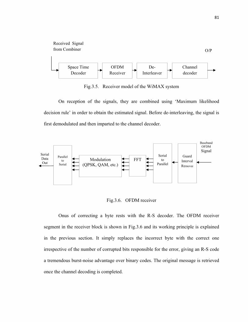
receiver block shown in Fig.3.5 consists of a demodulator, deinterleaver and a channel
decoder.
81
Fig.3.5. Receiver model of the WiMAX system
On reception of the signals, they are combined using ‘Maximum likelihood
decision rule’ in order to obtain the estimated signal. Before de-interleaving, the signal is
first demodulated and then imparted to the channel decoder.
Fig.3.6. OFDM receiver
Onus of correcting a byte rests with the R-S decoder. The OFDM receiver
segment in the receiver block is shown in Fig.3.6 and its working principle is explained
in the previous section. It simply replaces the incorrect byte with the correct one
irrespective of the number of corrupted bits responsible for the error, giving an R-S code
a tremendous burst-noise advantage over binary codes. The original message is retrieved
once the channel decoding is completed.
Space Time Decoder
OFDM Receiver
De-Interleaver
Channel decoder
Received Signal from Combiner O/P
Baseband OFDM Signal
Serial Data Out
Parallel to
Serial
Serial to
Parallel
Guard Interval Removal
FFT
Modulation (QPSK, QAM, etc.)

82
3.2.6. Results of WiMAX Diversity Analysis
BER is used to determine the performance levels/measure of the receiver models.
Fig.3.7 shows the BER comparison graph of SISO, MISO and MIMO schemes. The BER
comparison graphs illustrate the performance of the three diversity techniques contrary to
multipath fading.
It has been found that performance is heightened with the use of multiple
antennae at both the transmitter and receiver side rather than with a single antenna. By
using a single antenna scheme, the cumulative density of SNR declines due to fading
effect. For an Eb/No ratio of 35 dB, while the error rate for SISO is around 10-2, it is
about 10-6 for MIMO scheme with CTD, implying the possibility of improvement in SNR
by 20dB.
Fig.3.7. Comparison of diversity techniques
Eb/No (dB)

83
Considering the configuration in which, diversity technique is deployed only at
the transmitter side and single antenna is used at the receiver side, it has been found that
there is no appreciable improvement in SNR when compared to the MIMO scheme which
employed multiple antennae at the receiver side.
It is observed from figure that for a maximum value of 35dB for Eb/No, SISO
provides BER in the range of 10-2 to 10-3 and MIMO offers BER of 10-7, inferring the
possibility of 15dB improvement in Eb/No.
Fig.3.8. Comparison of modulation schemes
In Fig.3.10, for the max Eb/No at 25 dB, BER for BPSK is around 10-1, QAM
around 10-2 and QPSK stays around 10-6. Thus, QPSK with its lowest BER is logically
the ideal scheme for WiMAX systems. In case the of urban environments, when most of
the receiver antennae receive weak faded signals due to independent fading and by
increasing the number of antennae at transmitter and receiver side, there is still a
Eb/No (dB)

84
probability of at least one antenna receiving the least faded signal which dramatically
reduces the bit error rate, when compared to MISO and SISO schemes.
3.3. GRC and USRP Implementation of OFDM system
It is clearly understood from the earlier study that the OFDM is a good contestant
in broadband wireless communication systems to trim down multipath fading through
frequency scattering. To reveal the real time wireless channel characteristics, OFDM
transceiver is simulated in GNU Radio Companion(GRC) as shown in Fig.3.9 and a
sample image is transmitted and received.
Fig.3.9. GRC implementation of OFDM Transceiver

85
Fig.3.10. FFT plot of OFDM Transceiver
The FFT plot of OFDM transceiver simulated in GRC is shown in Fig.3.10. The
transmitted image in Fig.3.11 and received image in Fig.3.12 are compared to understand
the effect of poor channel quality. The degree of diversity can be increased by CTD to
perk up the quality of signal reception.

86
Fig.3.11. Transmitted Image
Fig.3.12. Received Image
87
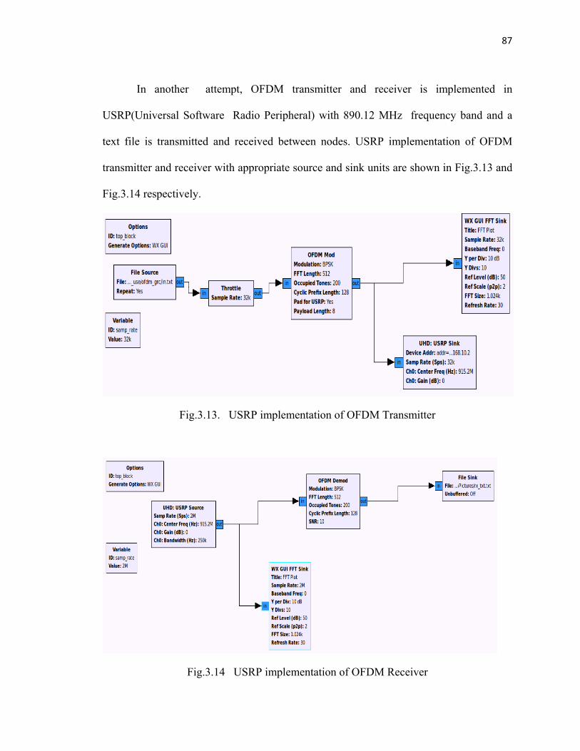
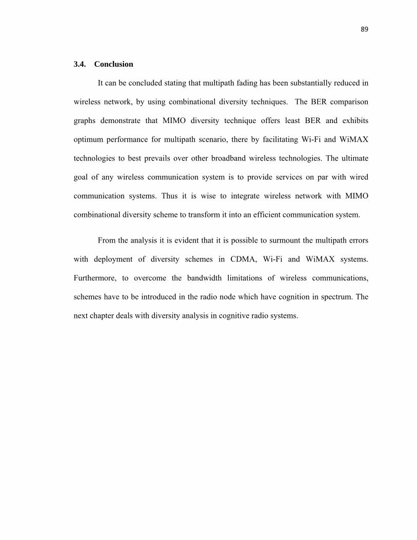
In another attempt, OFDM transmitter and receiver is implemented in
USRP(Universal Software Radio Peripheral) with 890.12 MHz frequency band and a
text file is transmitted and received between nodes. USRP implementation of OFDM
transmitter and receiver with appropriate source and sink units are shown in Fig.3.13 and
Fig.3.14 respectively.
Fig.3.13. USRP implementation of OFDM Transmitter
Fig.3.14 USRP implementation of OFDM Receiver

88
Multiple GSM(Global System for Mobile Communication) mobile phones were
in use while the transmission is initiated. This is to bring about the maximum interference
in the channel. The transmission is carried out with OFDM segment without channel
coding and is observed from the Fig.3.15 and Fig.3.16 that received file has got corrupted
in noisy channel. Since USRP provides real time implementation proposed CTD schemes
may also be tested.
Fig.3.15. Transmitted text file
Fig.3.16. Received text file
89
3.4. Conclusion
It can be concluded stating that multipath fading has been substantially reduced in
wireless network, by using combinational diversity techniques. The BER comparison
graphs demonstrate that MIMO diversity technique offers least BER and exhibits
optimum performance for multipath scenario, there by facilitating Wi-Fi and WiMAX
technologies to best prevails over other broadband wireless technologies. The ultimate
goal of any wireless communication system is to provide services on par with wired
communication systems. Thus it is wise to integrate wireless network with MIMO
combinational diversity scheme to transform it into an efficient communication system.
From the analysis it is evident that it is possible to surmount the multipath errors
with deployment of diversity schemes in CDMA, Wi-Fi and WiMAX systems.
Furthermore, to overcome the bandwidth limitations of wireless communications,
schemes have to be introduced in the radio node which have cognition in spectrum. The
next chapter deals with diversity analysis in cognitive radio systems.