Embed Size (px)
Citation preview

INSTALLATION INSTRUCTIONS
62-0433-01
WEB-600E and CP-600E Network Controllers
ABOUT THIS GUIDEThis document covers installation instruction of Honeywell's WEB-600E controller. It assumes that you are an engineer, technician, or service person who is performing control system installation. Instructions in this document apply to the following products:
NOTE: Not covered in this document is the WEBs-AX software installation and configuration required for a fully functioning unit. Refer to the JACE Niagara AX Install and Startup Guide for this information.In addition, the installation of controller expan-sion options are covered in separate documents. See Related Documentation, and also the section “About Expansion Options” on page 5.
The Content of this document equally applies to CP-600E product.
Related DocumentationFor more information on configuring and using the WEB-600E controller, refer to the following documents:• JACE NiagaraAX Install and Startup Guide• JACE Data Recovery Service (SRAM Support) -
Engineering Notes
• IO-16-H Installation and Configuration Guide• IO-34-H Installation and Configuration Guide• Various option card installation documents, such as:
— NPB-LON Option Install Sheet— NPB-2X-485 Option Install Sheet— NPB-RS232 Option Install Sheet— NPB-GPRS Modem Option Install Sheet— NPB-ZWAVE Option Card Install Sheet
• NiagaraAX Ndio Guide• NiagaraAX User Guide
PREPARATIONUnpack the controller and inspect the package contents for damaged or missing components. If damaged, notify the appropriate carrier at once and return any damaged components for immediate repair or replacement. See “Returning a Defective Unit” on page 17
• Included in this Package• Material and Tools Required
Included in this PackageIncluded in this package you should find the following items:• a WEB-600E or a CP-600E controller.• This WEB-600E and CP-600E Network Controllers, Part
Number 62-0433_A Rev 9/12• a hardware bag containing the following items:
— One (1) grounding wire, with quick-disconnect 0.187" female connector.
Material and Tools RequiredThe following supplies and tools are typically required for installation:• A suitable power module, as one of the following types:
— NPB-PWR-H: 24Vac or 24Vdc, in-line, DIN mount capable, with grounding wire
— NPB-PWR-UN-H: 120–240Vac, in-line, DIN mount capable, with grounding wire
— NPB-WPM-US: External wall mount power adapter (input 90-254 Vac, 50-60 Hz, output 15Vdc, 1A)
NOTE: Using an NPB-PWR-H power module provides the widest operating temperature range. See “Environmental Requirements” on page 3.
Model Description
WEB-600E,WEB-600E-USA,CP-600E,CP-600E-USA
DIN mount WEB-600E and CP-600E controller, powered by one of the two separate plug-in power supply modules, or by wall mount AC power adapter. Controller supports optional I/O expansion modules and internal communications option cards.
NPB-PWR-H 24Vac/dc input/15Vdc output power supply module, DIN mountable.
NPB-PWR-UN-H 120–240Vac universal input/15Vdc output power supply module, DIN mountable.
NPB-WPM-US External wall mount power adapter (input 90-254 Vac, 50-60 Hz, output 15Vdc, 1A)

WEB-600E AND CP-600E NETWORK CONTROLLERS
62-0433—01 2
• If using a NPB-PWR-H (24V) power module, either one of the following:— UL listed, Class 2, 24Vac transformer, rated at mini-
mum of 7.5VA to 20VA (approximate range of control-ler alone, to fully-expanded unit with four additional IO-16-H modules and other option boards). Note that a dedicated transformer is required (cannot also power additional equipment).
— 24Vdc power supply, capable of supplying at least 1A (24W).
• DIN rail, type NS35/7.5 (35mm x 7.5mm) and DIN rail end-clips (stop clips), recommended for any installation that includes NPB-PWR-H or NPB-PWR-UN-H power module and/or optional I/O modules.
• Suitable tools and fasteners for mounting unit and accessories.
• #2 phillips screwdriver: used to install and remove any option card.
• Small flat-blade screwdriver: used for making wiring connections to removable screw terminal plugs, also for mounting and removing modules from DIN rail.
PRECAUTIONSThis document uses the following warning and caution conventions:
CAUTIONCautions remind the reader to be careful. They alert readers to situations where there is a chance that the reader might perform an action that cannot be undone, might receive unexpected results, or might lose data. Cautions contain an explanation of why the action is potentially problematic.
WARNINGWarnings alert the reader to proceed with extreme care in situations where there is a chance that the reader might do something that can result in personal injury or equipment damage. Warnings contain an explanation of why the action is potentially dangerous.
Safety PrecautionsThe following are warnings relating to the installation and start-up of the controller. Be sure to heed these warnings to prevent personal injury or equipment damage.
WARNING• Depending on power module used, the circuit
powering the controller is 120–240Vac at 50/60 Hz (if a NPB-PWR-UN-H), 24Vac at 50/60 Hz or 24Vdc (if a NPB-PWR-H), or from 100–240Vac at 50/60 Hz (NPB-WPM-US). Disconnect power before installation or servicing to prevent electrical shock or equipment damage.
• Make all connections in accordance with national and local electrical codes. Use copper conductors only.
• To reduce the risk of fire or electrical shock, install in a controlled environment relatively free of contaminants.
• This device is only intended for use as a monitoring and control device. To prevent data loss or equipment damage, do not use it for any other purpose.
Static Discharge PrecautionsStatic charges produce voltages high enough to damage electronic components. The controller’s microprocessors and associated circuitry are sensitive to static discharge. Follow these precautions when installing, servicing, or operating the system:
CAUTION• Work in a static-free area. • Discharge any static electricity you may have
accumulated. Discharge static electricity by touching a known, securely grounded object.
• Do not handle printed circuit boards (PCBs) without proper protection against static discharge. Use a wrist strap when handling PCBs. The wrist strap clamp must be secured to earth ground.
Battery Precautions
CAUTION• The optional NiMH battery used in this device
may present a risk of fire or chemical burn if mistreated. Do not disassemble, heat above 122ºF (50ºC), or incinerate. Replace battery pack with type NPB-BATTonly. Use of another battery may present a risk of fire or explosion.
• Dispose of used battery promptly. Keep away from children. Do not disassemble and do not dispose of in fire.
• Replace external backup battery with Listed Power Source Battery Only.
WEEE (Waste of Electrical and Electronic Equipment) Recycling of Electronic Products: (International Installations)
In 2006 the European Union adopted regulations (WEEE) for the collection and recycling of all waste electrical and electronic equipment. It is no longer allowable to simply throw

WEB-600E AND CP-600E NETWORK CONTROLLERS
3 62-0433—01
away such equipment. Instead, these products must enter the recycling process. To properly dispose of this product, please take it to a local recycling center.
If a local recycling center cannot be found, please return it to one of these offices:
MOUNTINGMount the controller in a location that allows clearance for wiring, servicing, and module removal.
NOTES: This product is intended for indoor use only.
Depending on installed options, the allowable tem-perature range varies. See Environmental Require-ments below.
Avoid mounting the controller in a manner that would make it difficult to operate the disconnect device. See Physical Mounting for more details.
Before mounting the controller, install any option card(s). See “About Option Cards” on page 5. Also see “RS-485 Biasing” on page 11.
Environmental Requirements• Do not expose the unit to ambient operating temperatures
outside the range:— 0°C (32°F) to 60°C (140°F), providing the unit:
• Is not powered by the AC line input NPB-PWR-UN-H modulea, and
• The optional NiMH battery pack is not installed.
Otherwise, the maximum ambient operating temperature range is:
— 0°C (32°F) to 50 (122°F).• Do not expose the unit to humidity outside 5% to 95% non-
condensing (pollution degree 1). • If mounting inside an enclosure, that enclosure should be
designed to keep the unit within its required operating range considering a 20-watt dissipation by the controller, plus dissipation from any other devices installed in the same enclosure. This is especially important if the controller is mounted inside an enclosure with other heat producing equipment.
• Do not mount the unit:— in an area with excessive moisture, corrosive fumes,
or explosive vapors.— where vibration or shock is likely to occur. — in a location subject to electrical noise. This includes
the proximity of large electrical contactors, electrical machinery, welding equipment, spark igniters, and variable frequency drives.
Physical MountingThe following information applies about physically mounting the unit.• You can mount the controller in any orientation. It it not
necessary to remove the cover before mounting.• Mounting on a 35mm wide DIN rail is recommended. The
controller’s unit base has a molded DIN rail slot and locking clip, as do the power supply modules and both types of I/O expansion modules. Mounting on a DIN rail ensures accurate alignment of connectors between all modules.
• If DIN rail mounting is impractical, you can use screws in mounting tabs on the controller, as well as any end-connected accessory (NPB-PWR-H, etc.). Tab mounting dimensions are on the last page of this document.
Figure 1 and the following procedure provides step-by-step DIN rail mounting instructions for the controller.
Tridium Europe Ltd1, The GrainstoreBrooks Green RoadCoolham, West SussexRH13 8GR United Kingdom
Tridium Asia Pacific Pte Ltd17 Changi Business Park Central 1Honeywell BuildingSingapore 486073
Tridium, Inc.2256 Dabney Road, Suite CRichmond, VA 23230
a Powering the controller with the wall mount adapter (NPB-WPM-US) at 60°C (140°F) is supported, however, at 60°C its output is derated 50%, i.e. 15V at 0.5A (7.5W). No IO mod-ules are supported.

WEB-600E AND CP-600E NETWORK CONTROLLERS
62-0433—01 4
Fig. 1. WEB-600E controller and accessory mounting details.
To mount on DIN rail:1. Securely install the DIN rail with at least two screws,
near the two rail ends.2. Position the controller on the rail, tilting to hook DIN rail
tabs over one edge of the DIN rail (Fig. 1).3. Use a screwdriver to pry down the plastic locking clip,
and push down and in on the unit, forcing the locking clip to snap over the other DIN rail edge.
4. Mount any accessory module (I/O module, NPB-PWR-H) onto the DIN rail in the same manner.
5. Slide the accessory module along the DIN rail to con-nect its 20-position plug into the controller.
6. Repeat this for all accessories, until all are mounted on the DIN rail and firmly connected to each other.
7. To keep the final assembly together, secure at both ends with DIN rail end-clips provided by the DIN rail ven-dor. This also prevents the assembly from sliding on the DIN rail. See Fig. 1.
WEB-600E
IO-16-H
MOUNTING ON DIN RAIL
DIN RAILEND CLIP DIN RAIL
END CLIP
INSTALL DIN RAIL END CLIP(STOP CLIP) AT BOTH ENDS OFFINAL ASSEMBLY.
UP TO FOUR IO-16-H MODULESARE SUPPORTED.
7-1/8 (181)
6-3/8 (162)
2-3/64 (52)
4-7/64(104)
10-23/64 (263)13-37/64 (345)
16-13/16 (427)
M33914
REMOVING FROM DIN RAIL
NPB-PWR-H ORNPB-PWR-UN-H
WEB-600E
NPB-PWR-H or NPB-PWR-UN-H
20-3/64 (509)23-17/64 (591)
IF INSTALLING IO MODULES AND USING THE NPB-PWR-H OR NPB-PWR-UN-H POWER SUPPLY MODULE, THE POWER SUPPLY MODULE INSTALLS AT THE END OF THE CHAIN.
1
IO-16-H
WEB-600E

WEB-600E AND CP-600E NETWORK CONTROLLERS
5 62-0433—01
Removing and Replacing the CoverYou must remove the controller’s cover to install any option cards, or to install (or replace) the optional NiMH backup battery. The cover snaps onto the base with four plastic end tabs—two on each end.
Fig. 2. Press in four tabs on end to remove cover.
NOTE: If accessory modules are plugged into the con-troller, you may need to slide them away from the unit to get to the end cover tabs.
• To remove the cover, press in the tabs on both ends of the unit, and carefully lift it off.
• To replace the cover, orient it so the cutout area for comm ports is correct, then push inwards to snap in place.
Board LayoutFigure 3 shows the location of LEDs, option slots, and other features of the WEB-600E controller with cover removed. For a side view of communications ports and other features, see Fig. 6.
Fig. 3. WEB-600E controller main board layout details.
The controller ships with onboard static RAM (SRAM) that can provide station backup during power loss, and also has two (2) open option card slots for a variety of available option cards. For details, see “About Expansion Options” on page 5 below, and also “About Backup Configurations” on page 13.
ABOUT EXPANSION OPTIONSThe controller provides for field-installable expansion using these types of options:• Option cards — Install on connectors on the controller’s
base board. See “About Option Cards” on page 5.• Accessory modules — To “chain” on the controller’s 20-pin
connector. See “About Accessory Modules” on page 7.
About Option CardsThe WEB-600E has two (2) available option slots for option cards designed for use with WEB controllers. Each slot has a 30-pin connector. Installing an option card is recommended before mounting the unit. See “Installing an Option Card” on page 7.
COVER
PRESSTABS IN
COVERLIFTED AWAY
M33915
COVER TABS(2 EACH END)
EARTH GROUNDSPADE LUG
NORMALSERIAL SHELL
OPTION SLOT 2
COM 1COM 2
SERIAL PORT LEDS ON BOTTOM BOARD, REMOVE COVER TO SEE:
LAN2(SEC)
LAN1(PRI)
BEAT STATUSSTATUS LEDS (VISIBLE WITH COVER ON):
BRACKET FOROPTIONAL NIMH BACKUP BATTERY
OPTION SLOTCONNECTORS
OPTION SLOT 1
20-PINCONNECTOR(I/O ANDPOWERMODULES)
MODE JUMPER(FOR SERIAL SHELL ACCESS)
SECONDARYETHERNET(RJ-45) LAN2 (TOP BOARD)
RS-232(DB-9)COM1(BOTTOM BOARD)
BARREL POWERCONNECTOR FORWALL MOUNTED POWER MODULE(NPB-WPM-US)
PRIMARYETHERNET(RJ-45) LAN1 (TOP BOARD)
RS-485(3-POS.)COM2(BOTTOMBOARD)
NPM6E PROCESSORMODULE WITHINTEGRAL SRAM
M33918

WEB-600E AND CP-600E NETWORK CONTROLLERS
62-0433—01 6
WARNINGPower to the controller must be OFF when installing or removing option cards, or damage will occur! Also, you must be very careful to plug an option card into its connector properly (pins aligned).
Option cards typically provide additional communications features, with the following available models (with others still in development) listed in Table 2.
Table 1. WEB-600E Controller Option Card.
Option Description Notes
NPB-2X-485 Dual, optically-isolated, RS-485 adapter with two 3-position removable screw-terminal connector plugs.
If installed in Option slot 1, ports operate as COM3 and COM4. If two 485 option cards, ports are COM3, COM4 for Option slot 1, and COM5, COM6 for Option slot 2.
NPB-LON FTT-10A LON (LonWorks) adapterwith a 2-position removablescrew-terminal connector plug.
Port operates as LON1 if only one LON option, or LON2 in slot 2 if two LON cards.
NPB-RS232 Single port RS-232 adapter, with a DB-9M connector. Supports baud rates up to 115200.
If installed in option slot 1, port operates as COM3. If two 232 option cards, ports are COM3 for Option slot 1 and COM4 for Option slot 2.
NPB-GPRS-WNPB-GPRS
GSM cellular modem card using GPRS (General Packet Radio Service), with onboard socket for SIM card, and a Wyless SIM.
Includes SMA coax tilt-and-swivel antenna. The NPB-GPRS-W model is bundled with a Wyless-provisioned SIM card. The NPB-GPRS model does not include a SIM card.
NPB-ZWAVE-US or-EU
Z-Wave wireless serial gateway between the controller’s WEBs-AX station and an RF wireless Z-Wave domain. Includes RP-SMA coax tilt-and-swivel antenna.
-US model is 908.42 MHz for U.S. usage-EU model is 868.42 MHz for European usage. If installed in option slot 1, card operates as COM3.

WEB-600E AND CP-600E NETWORK CONTROLLERS
7 62-0433—01
Installing an Option CardFor option-specific details, see the mounting & wiring document that accompanies the particular option card. The following procedure provides a basic set of steps.
Mounting an option card in a WEB-600E controller:1. If a station is running, stop it using the platform Applica-
tion Director view.2. Remove power from the controller—see the previous
Warning.3. Remove the cover. See “Removing and Replacing the
Cover” on page 5. 4. If the optional NiMH battery/bracket assembly is
installed, remove it by taking out the four screws holding it place, setting them aside for later. Two of these screws will also secure the option card, once installed. a. Unplug the battery from the connector on the con-
troller’s base board.b. Remove the blanking plate from the option slot to be
used.5. If no optional NiMH battery/bracket assembly is
installed, remove the blanking plate for the option slot to be used, retaining the two screws.
6. If you are also installing the optional NiMH battery/bracket assembly now, remove and retain the other two screws, that is for the other option slot.
7. Carefully insert the pins of the option card into the socket headers of the option card slot.
The mounting holes on the option board should line up with the standoffs on the base board. If they do not, the connector is not properly aligned. Press until the option card is completely seated.
8. Place the custom end plate for the option card over the connector(s) of the option card. With some option cards, the card’s end plate is pre-fastened.
9. If installing (or replacing) the optional NiMH battery/bracket assembly:
a. Plug the battery connector plug into the battery con-nector on the controller’s base board.
b. Set the battery and bracket assembly over the option card slots, with the mounting holes aligned with the standoffs.
c. Place the four screws through the bracket, end plates, and into the standoffs on the controller base board. With a screwdriver, hand tighten the screws.
For more details, see “NiMH Battery Installation and Maintenance” on page 14.
Otherwise, place the two screws through the option card end plate and into the standoffs on the base board. With a screwdriver, hand tighten the screws.
10. Replace the cover on the controller.11. Restore power to the controller and verify normal opera-
tion.
About Accessory ModulesThe controller has a 20-pin, right-angle, Euro-DIN connector that accepts custom-built accessory modules. The connector provides power and signal lines to any connected modules.
WARNING• Power to the controller must be OFF when
inserting or unplugging accessory modules. Wait for all LED activity to stop (all LEDs off).
• Also, do not connect live voltages to the inputs or outputs of an I/O module while it is in an “un-powered state” before plugging the module into the controller.Otherwise, damage to the I/O module and/or controller may result!
Each accessory module has a DIN-mount base, and typically provides two (2) 20-pin connectors that allow you to “chain” multiple accessories. Table 3 lists the currently available modules.
Table 2. Accessory Modulesa Compatible with the WEB-600E Controller.
Model Description Notes
NPB-PWR-H DIN-mountable, 24V isolated power module, used to power the controller from a dedicated, external, Class-2, 24Vac transformer or a 24Vdc power supply.
Only one NPB-PWR-H per controller.Do not install if using NPB-WPM-US or NPB-PWR-UN-H.For wiring, see “NPB-PWR-H” on page 8.
NPB-PWR-UN-H DIN-mountable, Universal 120–240Vac input, 15Vdc output, 30W power supply to power the controller.
Only one NPB-PWR-UN-H per controller.Do not install if using NPB-WPM-US or NPB-PWR-H.For wiring, see “NPB-PWR-UN-H” on page 9.
IO-16-H DIN-mountable, 16 points I/O module, used to provide I/O points as noted.
Up to four (maximum) IO-16-H modules are supported. Each provides these I/O points:8 - Universal Inputs (UIs).4 - Digital Outputs (DOs), SPST-relay type.4 - Analog Outputs (AOs), 0–10Vdc type.Wiring is covered in the IO-16-H Installation and Configuration Guide.

WEB-600E AND CP-600E NETWORK CONTROLLERS
62-0433—01 8
WIRING DETAILSSee Fig. 3 to locate connectors and components on the controller.
Make connections to the controller in the following order:1. Install any option card (LON, RS-485, RS-232, etc.)
and/or approved MiniPCI card in the available option slots. See “Installing an Option Card” on page 7 for a procedure. For complete details, refer to the document that shipped with the option card.
If installing the optional NiMH battery, do that after inserting option card(s). See “NiMH Battery Installation and Maintenance” on page 14.
2. Connect supplied grounding wire from the earth ground lug on the controller, as well ground wire for each acces-sory module, to a nearby earth grounding point. See “Grounding” on page 8.
3. Prepare power wiring (leave unit powered off). See “Power Wiring” on page 8.
4. Connect communications cables. See “Communications Wiring” on page 10 for ports on the controller. For ports on any installed option card (485-PWR, LON, RS-485, modem) see the option’s specific mounting and wiring guide for details.
5. If I/O accessory modules are installed, connect I/O wir-ing. Refer to the appropriate mounting and wiring guide for details.
6. Apply power to the unit. See “Power Up and Initial Checkout” on page 13.
GroundingAn earth ground spade lug (0.187") is provided on the controller base for connection to earth ground. For maximum protection from electrostatic discharge or other forms of EMI, connect the supplied earth grounding wire to this lug and a nearby earth ground. Keep this wire as short as possible, see Fig. 4.
Also connect the earth ground spade lug of each accessory module to ground in the same manner.
Power WiringThe controller must be powered by an approved 15 Vdc power source. This can be eithera DIN-mountable module: the NPB-PWR-H, a 24Vac/dc-powered module, or the NPB-PWR-UN-
H, a line-powered 120–240Vac module. Or, an external Class 2 wall mount AC adapter (NPB-WPM-US) can be used for controller power.
The controller does not include an on/off switch. To apply power, you either:• if NPB-PWR-H, plug in its 2-position power connector.• if NPB-PWR-UN-H, energize the AC circuit (120–240 Vac)
wired to that module.• if NPB-WPM-US, plug in the power connector to the
controller.
CAUTIONDo not connect both the NPB-WPM-US and NPB-PWR-H / NPB-PWR-UN-H supplies at the same time, or equipment damage may result.
Power consumption depends mainly on installed I/O modules, and may vary from:• Controller alone (with or without installed option cards):
approximately 7.5 VA (AC) or 7.5 W (DC).• Controller (with or without installed option cards), plus four
(4) IO-16-H modules: up to 20 VA (AC) or 20 W (DC).If desired, you can use the wall mount NPB-WPM-US in your office (to initially commission the controller), and then install the controller at the job using either a NPB-PWR-H or NPB-PWR-UN-H module. The following sections provide more details:• “NPB-PWR-H” on page 8 (24Vac/dc-powered in-line
module)• “NPB-PWR-UN-H” on page 9 (Universal 120V–240Vac-
powered in-line module)• “NPB-WPM-US (Wall Mount AC Adapter)” on page 10
NPB-PWR-HUse the NPB-PWR-H module to power the controller (and if installed, IO-16-H modules) from a dedicated Class 2, 24Vac transformer, or from a 24Vdc power supply.
NOTE: If there is no optional NiMH backup battery, using the NPB-PWR-H allows a higher operating tem-perature. See “Environmental Requirements” on page 3.
IO-34-H DIN-mountable, combined 34 points I/O with 24V isolated power module, used to provide I/O points as well as power the controller from a dedicated, external, Class-2, 24Vac transformer or a 24Vdc power supply.
Only one IO-34-H module per controller.This module provides these I/O points:16 - Universal Inputs (UIs).10 - Digital Outputs (DOs), SPST-relay type.8 - Analog Outputs (AOs), 0–10Vdc type.Wiring is covered in the IO-34-H Installation and Configuration Guide.
a A wall mount AC adapter (NPB-WPM-US) is also available; however, it is not an accessory module that mounts on the 20-pin connector of the controller.
Table 2. Accessory Modulesa Compatible with the WEB-600E Controller. (Continued)
Model Description Notes
a A fourth power option is available: a IO-34-H accessory module, which is a combination of the NPB-PWR-H module and two IO-16-H modules (plus two extra relays). Refer to its mounting and wiring document for more details. For a listing of modules, see “About Accessory Modules” on page 7.

WEB-600E AND CP-600E NETWORK CONTROLLERS
9 62-0433—01
NOTE: If powering from a 24V transformer, do not power any other equipment with it. Otherwise, con-ducted noise problems may result. Also, do not ground either side of the transformer’s 24V sec-ondary.
Fig. 4. NPB-PWR-H module wiring connections.
Located at the bottom of the NPB-PWR-H module is a 2-position power connector, and an earth ground spade lug, as shown in Fig. 4.
Connect the supplied earth ground wire to a nearby earth ground point. Unplug the power connector plug from the module and make connections to it as shown.
CAUTIONDo not plug 24V power into the NPB-PWR-H (reinsert connector plug) until all other mounting and wiring is completed. See “Power Up and Initial Checkout” on page 13.
NPB-PWR-UN-HThe NPB-PWR-UN-H module lets you power the controller (and if installed, connected I/O modules) from AC line power, with a universal input range from 120–240Vac. If installing IO-16-H modules, the NPB-PWR-UN-H module mounts as the last (end) module in the chain. (see Fig. 1).
WARNING• A 120Vac or 240Vac circuit powers the NPB-
PWR-UN-H. Disconnect power to this circuit before installation to prevent electrical shock or equipment damage.
• Make all connections in accordance with national and local electrical codes. Use copper conductors only.
• Do not exceed the 30W capacity of NPB-PWR-UN-H by the powered devices.
Fig. 5. NPB-PWR-UN-H module wiring connections.
Wiring NPB-PWR-UN-H input power and earth ground:1. Remove power from the AC circuit being wired to the
NPB-PWR-UN-H. See the previous Warning.2. Remove the NPB-PWR-UN-H cover.
+–
NPB-PWR-H (COVER REMOVED)
24VDC
SUPPLIED EARTHGROUNDING WIRE
EARTHGROUND
24VACOR
24VDC POWER SUPPLY(POLARITY NOT CRITICAL)
NEITHER SIDE TIED TO EARTH
DEDICATED 24VAC TRANSFORMERNEITHER SIDE OF SECONDARY TIED
TO EARTH GROUND
MCR33926
SUPPLIED EARTHGROUNDING WIRE
EARTHGROUND
NOTE: THE 6-PIN CONNECTOR ON THE NPB-PWR-UN-H IS NOT USED WITH A WEB-600E SERIES CONTROLLER. THE 6-PIN CONNECTOR IS DESIGNED FOR USE WITH OTHER CONTROLLERS OR MODULES, AND MUST BE LEFT UNUSED.
REMOVECOVER
6-PINCONNECTORNOT USED
120 OR 240VAC50–60 HZSINGLE PHASE
LINE
NEUTRAL
L N
M33919

WEB-600E AND CP-600E NETWORK CONTROLLERS
62-0433—01 10
3. To do this, press in the four tabs on both ends of the unit, and lift the cover off. If the controller or a IO-16-H accessory module is plugged into the unit, you may need to slide it away to get to the cover tabs.
4. Connect the supplied earth grounding wire to a nearby grounding point. See Fig. 5.
5. Make AC circuit connections line (mains) and neutral to the terminals labeled “INPUT PWR.”
6. Replace the cover on the NPB-PWR-UN-H module.7. Make sure all modules in the mounted assembly are
firmly connected together and secured.
CAUTIONDo not energize the AC circuit wired to the NPB-PWR-UN-H until all other controller mounting and wiring is completed. See “Power Up and Initial Checkout” on page 13.
NPB-WPM-US (Wall Mount AC Adapter)All models of wall power modules (US, EUR, UK) are self-contained, isolated, Class 2, switching power supplies designed to plug into a standard building power receptacle of appropriate voltage. To supply power to the controller, you
simply plug the barrel connector plug from the NPB-WPM-US into the barrel power connector on the controller’s base board (see Fig. 3).
Note the adapter’s 15W output rating is derated 50% at the 60°C (140°F) maximum ambient temperature (for a controller without a NiMH battery), such that no I/O modules are supported at 60°C. See “Environmental Requirements” on page 3.
CAUTIONDo not plug the barrel connect plug from the NPB-WPM-US into the controller until all other mounting and wiring is completed. See “Power Up and Initial Checkout” on page 13.
Communications WiringCommunications ports are on the controller’s bottom side, which include:• Ethernet• Serial
NOTE: Prior to connecting cables, provide strain relief for them to prevent damage to the controller.
Fig. 6. WEB-600E controller bottom side (cover removed).
ETHERNETTwo, female 10/100-Mbit Ethernet connections are provided on the controller. These RJ-45 connectors are labeled LAN1 (PRI) and LAN2 (SEC). Use a standard Ethernet patch cable for connecting to a hub or Ethernet switch.
The factory-default IP address for LAN1 is 192.168.1.12n, where the last numeral n in the address matches the last digit in the controller’s serial number, and the subnet mask is 255.255.255.0. By default, LAN2 is disabled.
NOTE: Typically, you only use LAN1 (primary port), unless you have a specific application for the other LAN2 port. For example, isolating a driver’s network traffic, using LAN2. Do not use LAN2 as the primary port.
NOTE: If enabling LAN2, note that LAN1 and LAN2 must be connected to different subnets. Further, a WEBs controller does not provide IP routing or bridging operation between the two LAN ports.
Refer to the JACE NiagaraAX Install and Startup Guide for details on changing IP address using the platform Commissioning Wizard (TCP/IP configuration step).
SERIALThere are two “RS” serial ports on the controller’s base board. Each has a UART capable of operation up to 115,200 baud. At the bottom of the board (see Fig. 6) is an RS-232 port using an DB-9 plug (male) connector. To the right of this is a two-wire plus shield RS-485 port, using a 3-position screw-terminal connector plug.
NOTE: A green “receive” LED and yellow “transmit” LED are provided for both serial ports. These LEDs are on the controller’s bottom board, on the side opposite to the serial connectors (see Fig. 3). These LEDs are labeled on the board (COM1, COM2) and are not visible with the cover on.
RS-232An RS-232 serial port using a male DB-9 connector always operates as COM1. You can use standard DB-9 serial cables with this port.
M33920
EARTH GROUND SPADE LUG
PRIMARYETHERNET (RJ-45) LAN 1
SECONDARY ETHERNET (RJ-45) LAN 2
OPTIONAL NIMH BATTERYAND BRACKET ASSEMBLY, IFINSTALLED, MOUNTS ON TOPOF THE OPTION SLOT AREA.
RS-485(3-POS.)COM2
RS-232(DB-9)COM1
BARREL POWERCONNECTOR FORNPB-WPM-US (WALLMOUNT AC)
20-PINCONNECTOR(I/O ANDPOWERMODULES)
OPTIONSLOT AREA(SLOT #1THIS SIDE)

WEB-600E AND CP-600E NETWORK CONTROLLERS
11 62-0433—01
The controller is a serial DTE device, such that another DTE device (PC, for example) requires a “null modem” cable. If connecting to a DCE device such as a modem, use a straight-through cable. Table 2 provides standard serial DB-9 pinouts.
NOTE: If rebooted with the mode jumper in the “Serial Shell” position (see Fig. 3), the RS-232 port pro-vides “system shell” access. See the JACE Niag-araAX Install and Startup Guide for related details.
.
RS-485An RS-485 port uses a 3-position, screw terminal connector, and always operates as COM2. As shown in Table 2 pinouts, from left-to-right the screw terminals are shield (S), plus (+), and minus (–). Wire in a continuous multidrop fashion to other RS-485 devices, meaning “minus to minus,” “plus to plus,” and “shield to shield.” Connect the shield to earth ground at one end only, such as at the controller.
RS-485 BiasingThe RS-485 port on the controller’s base board has a pair of two-pin jumpers that can be shorted with jumper blocks to provide “biasing.” As shipped from the factory, these pins are not shorted, thus the RS-485 port is unbiased.
NOTE: See Need for RS-485 Bias before following the Adding RS-485 Bias procedure. In many cases, the default unbiased RS-485 port is preferred.
Need for RS-485 Bias
NOTE: A full discussion of communication line termina-tion is beyond the scope of this document.
Biasing sometimes improves RS-485 communications by eliminating “indeterminate” idle states. When you install two, 2-pin shorting blocks on the controller’s RS-485 bias jumper pins, this adds two onboard 3.3K ohm resistors into the controller’s RS-485 circuit, as follows:• from RS-485 “+” to 5V.• from RS-485 “-” to Ground.
NOTES: In general, only one device on an RS-485 trunk should be biased. Otherwise, undue loading of the circuit may result, with fewer devices supported.
RS-485 bias resistors are different than “termination resistors,” externally installed at the two physical ends of a daisy-chained RS-485 trunk, across the “+” and “–” terminals. Termination resistors are typically 100 or 120 ohm value resistors.
Whenever termination resistors are used, RS-485 biasing is typically required.
Adding RS-485 BiasTo add biasing, you must power off the controller and remove some assemblies (including metal shield and the NPM6E processor module) to access the base board jumper pins, located behind the RS-485 port. Then you must reposition the two shorting blocks on these jumper pins. Then you reassemble the unit by remounting the NPM6E processor module, hex standoffs, metal shield, and shield screws.
WARNINGRemove all power from the controller before working on the unit. Observe static discharge precautions. See “Static Discharge Precautions” on page 2.
If the controller is already installed or mounted, it is recommended that you remove it first. Then work on a flat, stable, well-lit work surface.
Table 3. Base Serial Port (RS-232 and RS-485) Pinouts.
Base RS-232 DB-9 Port (COM1) RS-485 Port
(COM2)
Pinout Reference Signal DB-9 Pin Pinouts
DB-9 Plug (male) DCD Data carrier detect 1 3-Position connector
(male)
RXD Receive data 2
TXD Transmit data 3
DTR Data terminal ready 4
GND Ground 5
DSR Data set ready 6
RTS Request to send 7
CTS Clear to send 8
not used on the JACE 9
S –+

WEB-600E AND CP-600E NETWORK CONTROLLERS
62-0433—01 12
Fig. 7. Basic stages of controller disassembly.
Disassembling the controller:1. Remove all power from the controller. (See previous
Warning.).2. Remove the plastic cover. See “Removing and Replac-
ing the Cover” on page 5.3. Remove the four Phillips head screws that secure the
metal shield, and set them aside.4. Remove the metal shield and set it aside.
To do this, carefully pry up from the top (hole vented side) first, then push out the other side to slip the port holes past the port edges. Then lift the shield up and away.
NOTE: Be mindful of the “side clips” on the controller’s two Ethernet ports.
5. Use a 1/4" (7mm) nutdriver to unscrew the four metal standoffs, and set them aside.
6. Carefully pry up the NPM6E board, noting that the two-row, 50-pin connector is on the option card side. Keep the board level as you work it loose from this connector.
7. Set the NPM6E board aside. Note the jumper block on the base board behind the RS-485 port (see bottom of Fig. 7).
Fig. 8. Install shorting blocks across both sides of jumper block to add RS-485 bias.
Installing short blocks to add RS-485 biasing:1. Locate the four jumper pins behind the RS-485 port,
with 2-pin shorting blocks installed on one pin each. See Fig. 8.
2. To add biasing, remove and replace both shorting blocks back onto the jumper pins, as shown in Fig. 8 (right).
Reassembling the controller:1. Carefully replace the NPM6E board back onto the 50-
pin connector, with its corner mounting holes aligned on the four lower standoffs. Press down on the connector to fully seat the NPM6E board. See Fig. 7.
2. Refasten the four metal hex standoffs, hand tightening with a 1/4” (7mm) nutdriver.
PHILLIPSHEADSCREWS
METAL STANDOFFS
METAL SHIELDLIFTED AWAY
COVER REMOVED,REVEALS METAL SHIELD
NPM6EBOARD
NPM6E BOARDLIFTED AWAY
JUMPER BLOCK FOR RS-485 BIASING
1
2
3
M33921
POSITION OF PRE-INSTALLED SHORTINGBLOCKS (NO BIASING)
SHORTING BLOCKSINSTALLED ACROSSJUMPER PINS(BIASING ADDED)
SHORTINGBLOCKS LIFTEDAWAY
M33922

WEB-600E AND CP-600E NETWORK CONTROLLERS
13 62-0433—01
3. Replace the shield back onto the unit. To do this, care-fully ease it over the port side first, then spring it down over the other side. Make sure that its corner holes align with the metal standoffs below.
4. Refasten the four Phillips head screws that secure the shield to the standoffs.
5. Replace the plastic cover onto the unit.
POWER UP AND INITIAL CHECKOUTEnsure power wiring to the controller is ready—see the “Power Wiring” on page 8. See Fig. 3 for the location of status LEDs and connectors. See Fig. 4 for the location of the NPB-PWR-H module’s power connector.
After completing all mounting and wiring, do the following:1. Apply Power.2. Check the Status LED.
Also see the section “About Backup Configurations” on page 13.
Apply PowerTo apply power, insert the power plug into either the NPB-PWR-H module, or if using a NPB-WPM-US wall adapter, the controller. If using the line-voltage input NPB-PWR-UN-H power supply module, energize the 120–240Vac circuit wired to the module.
CAUTIONDo not connect both the NPB-WPM-US and NPB-PWR-H / NPB-PWR-UN-H supplies at the same time, or equipment damage may result.
Check the Status LEDWhen power is applied, the green LED labeled “STATUS” will light. This indicates that the system is OK and that power is applied. Once the controller boots, the yellow “BEAT” LED should start blinking, at a typical rate of 1Hz. Blinking should begin about 30 seconds after power is applied.
If after applying power, the STATUS LED goes out, or if the BEAT LED comes on (steady) and stays lit longer than 2 minutes, contact Systems Engineering for technical assistance. See also “Status LEDs” on page 14.
ABOUT BACKUP CONFIGURATIONSA WEB-600E series controller allows two separate and configurable methods to preserve unsaved station data when "power quality events" occur, including loss of primary power or low-voltage dips (brownout): • Using the integral static RAM (SRAM) on the controller’s
NPM6E processor module. This default method can allow the unit to operate “battery-less”, that is, without installing the optional NiMH battery pack. Note in this configuration a controller reboot is likely to occur whenever a power outage or voltage dip is sustained for more than one AC line cycle (1/50th or 1/60th of a second) or a number of line cycles,
depending on the load and power supply. Critical station data will already be saved prior to any power quality event, but the NiMH battery option is available to prevent nuisance controller reboots/station restarts during extended or frequent power outages.
• An optional on-board NiMH battery pack. Installing this battery allows the controller to continue operation (without rebooting) over short power outages or brownouts lasting several seconds (or if also using SRAM, up to 10 minutes). For longer duration outages, the battery allows the controller to perform a “controlled shutdown”, safely backing up the station before shutting down.
Starting in the AX-3.6.nn maintenance build, the controller can use both the NiMH backup battery and available SRAM for backup protection (prior to this, SRAM support required removing backup batteries). Configuring for both backup battery and SRAM support provides the most comprehensive backup protection. This allows the controller to “ride out” brief power outages, while also protecting against a scenario of a battery too weak (or aged) to perform a controlled shutdown.
SRAMThe WEB-600E controller’s NPM6E processor module includes on-board SRAM and associated circuitry, allowing “battery-less” operation. This is the same circuitry as provided by the “SRAM option card” for earlier QNX-based Controllers, available since the initial release of AX-3.6. Therefore, an SRAM option card is not needed (or supported) in a WEB-600E controller.
The default configuration is to use SRAM for station backup, via the platform “DataRecoveryService” that is automatically created in the controller’s running station. However, in some cases, a station may be a poor candidate for SRAM support, requiring too many resources by this associated platform service. An example is a station with many rapidly changing values all captured as histories, on COV. In this case, you may wish to disable SRAM support, and install and use only the optional NiMH battery pack.
For an overview, see “About Backup Configurations” on page 13. Complete WEBs-AX details on the operation of the WEB-600E’s integral SRAM are in the WEB Data Recovery Service (SRAM support) - Engineering Notes document.
NiMH battery packA custom 10-cell NiMH (nickel metal hydride) battery assembly is available as a separately orderable option for the WEB-600E controller. This battery assembly incudes a metal bracket with the tie-wrapped NiMH battery pack. It is the same battery assembly installed in the previous WEB-200/600, CP-200/600 series controllers.
This battery allows the controller to continue station operation through short power bumps, ranging from a few seconds to a minute or more in duration (up to 10 minutes, if also using SRAM). If a longer outage, the NiMH battery provides enough run time for the unit to backup data and then shutdown. Shutdown occurs automatically, after data is backed up to on-board flash memory.
The controller charges the battery during normal operation, until fully charged. Typically, the charge operation completes within 18 hours. Following a power outage, the battery is charged again, as necessary. The power and battery circuitry is monitored by a station running on the controller (via its

WEB-600E AND CP-600E NETWORK CONTROLLERS
62-0433—01 14
PowerMonitorService). Station alarms are generated whenever primary power is lost, or if the battery is uncharged or unable to hold a sufficient charge.
NOTE: A NiMH battery characteristic is to lose charge if not left in charge mode (trickle charge). Leaving the battery unconnected, or in the unit powered off will cause the battery to fully discharge in a matter of weeks. Note that a new NiMH battery may be partially discharged. Therefore, allow at least 18 hours for a new battery to charge if it has not been in a powered unit.
The NiMH battery assembly should be replaced approximately every three years, or more often if the unit is in a high temperature environment. For more details, see “NiMH Battery Installation and Maintenance” on page 14
STATUS LEDSThe controller includes several LEDs that can help determine the status of the unit. They are located in two places: the top of the controller, visible through the cover, and for serial ports, on the bottom board (only with cover removed).
Ethernet PortsEach Ethernet port has a green LED, labeled on the top cover “LAN2” (or “SEC”), and “LAN1” (or “PRI”). The LED indicates activity on that LAN2 (secondary) port or LAN1 (primary) port as follows: • Off — No Ethernet link is made.• On — Ethernet link is present, but no activity on the LAN.• Blinking — Ethernet link is present with data activity on
the LAN.
HeartbeatThe yellow heartbeat “HBEAT” LED is next to the Ethernet status LEDs, and is visible on the cover. Under normal operation, this LED should blink about once per second. If the heartbeat LED stays on constantly, does not light, or blinks very fast (more than once per second), contact System Engineering for technical support.
StatusThe green “STATUS” LED is next to the heartbeat LED, and is visible on the cover. This LED provide a CPU machine status check, and should remain lit whenever the controller is powered. If the status LED does not light while power is applied, contact System Engineering for technical support.
Serial PortsLEDs for the two serial ports are located on the controller’s bottom board, on the opposite side of the RS-232 and RS-485 ports. Labels “COM1” and “COM2” correspond to the software configuration of the COM ports. LEDs show the transmit and receive activity for the serial ports and optional modem.
NOTE: You must remove the cover to see these LEDs. See “Removing and Replacing the Cover” on page 5.
• The yellow transmit LED indicates that the controller is sending data out the serial port over a communications line to a connected device.
• The green receive LED indicates that the controller is receiving data from a connected device.
Serial port LEDs provide a fixed on-time when data is detected on the port. If the receive LED is on constantly, this indicates a problem with the communications channel, such as a shorted wire or reversed wiring.
MAINTAINING THE CONTROLLERThis section provides information on the following topics:• Cleaning• NiMH Battery Installation and Maintenance (optional)• Replacement Parts• Replacing the Controller Base Assembly• Returning a Defective Unit
CleaningIf dust or metal filings are present inside the unit, clean with vacuum or compressed air. Otherwise, no cleaning inside the unit is required. Optionally, if the cover becomes dirty, you can wipe it with a damp cloth and mild detergent.
NiMH Battery Installation and Maintenance• Installing or replacing the optional NiMH battery• Battery maintenance• Battery disposal
Installing or replacing the optional NiMH batteryThe optional NiMH battery pack is sold as an assembly, that is a custom battery pack with an attached cable and connector plug, mounted on a bracket. To install (or replace) the battery, you must remove power to the controller and remove its cover. Then you mount the battery assembly on top of the option card area (Fig. 9).
From left-to-right these LEDs include:Visible on cover:• Ethernet
Ports• Heartbeat• StatusBottom board only:• Serial
Ports
FROM LEFT-TO-RIGHT THESE LEDS INCLUDE:
COM 2
SERIAL PORT LEDS ON BOTTOM STATUS LEDS (VISIBLE WITH COVER ON):BOARD, REMOVE COVER TO SEE: BEAT STATUS
COM 1
VISIBLE ONCOVER:
• ETHERNET PORTS
• HEARTBEAT
• STATUS
BOTTOMBOARD ONLY:
• SERIAL PORTS
MCR33925
LAN2(SEC)
LAN1(PRI)

WEB-600E AND CP-600E NETWORK CONTROLLERS
15 62-0433—01
Fig. 9. Optional NiMH battery pack in WEB-600E controller.
CAUTIONUse only NiMH battery packs approved for use with the WEB-600E.
Installing/replacing a NiHM batter assembly on a WEB-600E:1. If replacing an existing battery in a controller not cur-
rently configured for SRAM usage, backup the control-ler’s configuration to your PC using the appropriate WEBs-AX software tool (for example, Workbench).
2. If a station is running, stop it using the platform Applica-tion Director view.
3. Remove all power from the controller. Wait for all LED activity to stop (if a battery is already installed, this may take a minute or two).
4. Remove the cover. See “Removing and Replacing the Cover” on page 5.Note the Option Slot area where the NiMH battery assembly mounts.
5. If a battery assembly is already mounted, unplug the battery from the connector on the controller board (see Fig. 9).
6. Remove the four screws that secure both option slot end plates (and if installed, the existing battery assem-bly bracket). Set the screws aside.
7. Remove any existing battery assembly (if applicable).8. Plug the battery connector plug of the new battery
assembly into the battery connector on the controller (see Fig. 9).
9. Set the new NiMH battery assembly on top of the option card slots, over the option card end plates. Ensure the bracket mounting holes are aligned with the standoffs.
10. Place the four screws through the battery bracket, option card end plates, and into the standoffs on the controller’s base board. Using a screwdriver, hand tighten these screws.
11. Replace the cover.12. Restore power to the controller and verify normal opera-
tion.
Battery maintenanceBattery life expectancy is a function of its discharge cycles (the number of discharges and their depth) and the ambient temperature of the battery during normal operation. In most applications, the NiMH battery should see relatively few discharges. Therefore, ambient temperature has more to do with the life expectancy of the battery than does any other factor. If the controller is installed in a conditioned space, this battery should provide dependable service for approximately three years (average). In an environment where the operating temperature reaches the highest range (50ºC or 122ºF), you should only expect the battery to last around one year.
A new NiMH battery is typically only partially charged when shipped. Additionally, NiMH batteries lose charge over time if not kept trickle-charged (for more details, see “NiMH battery pack” on page 13). Therefore, even a new or replacement battery will require up to 18 hours of powered operation before it can provide reliable backup power (is at full charge).
The controller monitors the NiMH battery and periodically loads the battery to test its ability to maintain battery-backed functions. Investigate any battery trouble message, and check the battery connections to the unit. Replace the battery as required. To order a new battery, see “Standard Replacement Parts” on page 16.
Battery disposalPlease dispose of the used NiMH battery in accordance with local, state, and federal regulations.
WARNINGDo not incinerate or mutilate the battery, as this may cause it to burst or release toxic materials.
If regulations specify returning the old battery to a recycling center, but no acceptable recycling center can be found, please return the old NiMH battery pack to Tridium for proper disposal.
INSTALLED NIMH BATTERY ASSEMBLY
BRACKETPART OFASSEMBLY
WEB-600E CONTROLLER WITH COVER REMOVED
OPTIONAL NIMHBATTERYASSEMBLY(NPB-BATT)
MOUNTINGSCREWS (4)
NIMH BATTERYPLUGGED INTOCONNECTOR ONCONTROLLER
M33923
NIMH BATTERYCONNECTOR ONCONTROLLER BOARD

WEB-600E AND CP-600E NETWORK CONTROLLERS
62-0433—01 16
REPLACEMENT PARTSServicing the WEB-600E controller may call for replacement parts. There are three categories of parts: • Non-replaceable Parts• Standard Replacement Parts• New Replacement Unit
Non-replaceable PartsOther than the parts listed in the replacement parts sections, there are no serviceable components on the base assembly.
MemoryAny addition, modification, or replacement of memory components requires software configuration and is not a field upgrade. For additional information on modifying the memory capacity of the controller, consult your regional Tridium office.
FUSEThe controller contains a non-user replaceable fuse, soldered on the circuit board. This fuse provides protection from internal shorts or connection to incorrect power supplies. If the fuse circuitry is suspect, contact your regional Tridium office for technical support. See “Returning a Defective Unit” on page 17.
Standard Replacement PartsStandard replacement parts are listed in Table 4, and can be ordered from stock without restriction. Standard replacement parts cannot be returned for credit and should be disposed of in an appropriate manner.
New Replacement UnitTo replace an entire unit, order and install a new WEB-600E controller. If the faulty controller is still in warranty, you can receive credit by returning it. Be sure to contact the vendor for a return authorization (RA) number before shipping an item for return credit. See “Returning a Defective Unit” on page 17, for more details.
NOTE: Before ordering a new controller, it is strongly recommended that you contact your normal technical support resource to eliminate the pos-sibility of a software issue or mis-configuration problem.
Replacing the Controller Base AssemblyNOTE: Before handling circuit boards, discharge any
accumulated static by touching a nearby earth ground. For details, see “Static Discharge Pre-cautions” on page 2.
To replace a WEB-600E with a new replacement unit, proceed as follows:
1. If possible, use the appropriate WEBs-AX software tool to back up the controller’s configuration to your PC.
2. Remove power to the controller. The unit should power down automatically. Wait for all LEDs to remain off.
NOTE: If IO accessory modules are installed, and any I/O points have voltage, turn the devices off or dis-connect power to them.
3. Note positions of all communications and other wiring cables going to the controller, as well as installed acces-sory modules (if they must be removed). If necessary, label connectors and accessory modules to avoid mis-connection later, after the controller is replaced.
4. Unplug all Ethernet, serial, LON, modem, and I/O con-nectors from the controller.
5. If IO accessory modules are installed:— If DIN rail mounting with DIN end-clips was used, you
may be able to remove the DIN rail end clip that secures the WEB-600E end of the assembly, and then slide the controller away from the rest of the assembly. Then you can remove the controller from the DIN rail (see Fig. 2), leaving the mounting and wiring of IO modules untouched. In this case, after removing the controller from the DIN rail, go to 6.
— If tab (screw) mounting was used instead of DIN rail mounting, or if a combination of DIN mounting and tab screws was used (into the controller’s “accessory side” tab holes, see last page), you will need to remove accessory modules first, before removing the control-ler. In this case:
a. Making a careful note of all wiring terminations, unplug the I/O connector plugs and earth ground wires from the installed IO modules.
b. Remove the installed accessory modules, starting with the end module.
c. c Remove any screws fastening the controller, and remove it (see Fig. 1).
6. Remove the cover of the old unit. See “Removing and Replacing the Cover” on page 5. Note the position of installed option cards, if any. You must transfer them to the replacement controller.
7. Remove any option cards from the old controller and install them into the replacement WEB-600E controller, if applicable. See “Installing an Option Card” on page 7 for more details.
8. Check the RS-485 biasing jumpers on the existing unit, and duplicate on the replacement unit (see “Installing an Option Card” on page 7).
9. Mount the replacement controller as it was previously, using the same DIN rail location and/or screws.
10. Reconnect/remount any removed accessory modules, being careful to replace in the same order, using the same DIN rail location and/or screws. Secure all mod-ules as done previously.
Table 4. Standard replacement parts for a WEB-600E controller.
Part Number Description
WEBs-AX Optional NiMH Battery Pack—see “NiMH Battery Installation and Maintenance” on page 14
H10027 RS-485 connector plug, 3-position.

WEB-600E AND CP-600E NETWORK CONTROLLERS
17 62-0433—01
11. Reconnect the earth ground wire to the controller’s grounding lug and any installed accessory modules.
12. Reconnect any Ethernet, serial, modem, and I/O con-nectors.
13. If using IO modules, and any of your I/O points have voltage, turn the devices back on, or reconnect power to them.
14. Replace the cover. See “Removing and Replacing the Cover” on page 5.
15. Restore power to the unit. It should boot up as a new unit (see “Check the Status LED” on page 13).
16. Using the WEBs-AX platform tools, re-commission the controller, and install the saved station database. For more details, see the JACE NiagaraAX Install and Startup Guide.
Returning a Defective UnitFor proper credit on an in-warranty unit, ship the defective unit per the vendor’s return material procedures.
NOTE: If the defective unit is under warranty, please fol-low return instructions provided in this section. If the unit is out of warranty, please discard any replaced part.Do not return an out-of-warranty WEB-600E con-troller.
Prior to returning the unit, contact your vendor to obtain a return materials authorization (RMA) number and other instructions.
Please provide:• Product model• Serial number• Nature of the defect• PO number to secure the RMA
UNITED STATESPhone: 804-254-7086, ext. 11Email for RMA: [email protected]
Return to:
Tridium, Inc.2256 Dabney Road, Suite CRichmond, VA 23230Attn: Return Department RMA# ____________
EUROPEPhone: +44 (0) 1403 740290Fax: +44 (0) 1403 741804Email for technical support: [email protected] for product orders: [email protected]
Return to:
Tridium Europe Ltd1, The GrainstoreBrooks Green RoadCoolham, West SussexRH13 8GR United KingdomAttn: Return Department RMA# ____________
ASIA/PACIFICPhone: +65 6887 5154Fax: +65 6887 5342Email for technical support: [email protected]
Return to:
Tridium Asia Pacific Pte Ltd17 Changi Business Park Central 1Honeywell BuildingAttn: Mr Lim Hoon Chat, Engineering Mgr.Singapore 486073Attn: Return Department RA# ____________
Australia/Asia Pacific Sales:Phone: +61 4 1264 4234Email: [email protected]
CERTIFICATIONS
Federal Communications Commission (FCC)This equipment generates, uses, and can radiate radio frequency energy, and if not installed and used in accordance with the instruction manual, may cause interference with radio communications. It has been tested and found to comply with the limits for a Class A computing device pursuant to Subpart J of Part 15 of FCC Rules, which are designed to provide reasonable protection against such interference when operated in a commercial environment. Operation of this equipment in a residential area may cause interference, in which case, users at their own expense will be required to take whatever measures may be required to correct the interference. Any unauthorized modification of this equipment may result in the revocation of the owner's authority to continue its operation.
Canadian Department of Communications (DOC)This Class A digital apparatus meets all requirements of the Canadian Interference-Causing Equipment Regulations.
Cet appareil numerique de la classe A respecte toutes les exigencies du Reglement sur le material broilleur du Canada.
Declaration of RoHS Compliance This product meets all requirements of RoHS Directive (EU 202/95/EC). All components used in this product are RoHS compliant and there have been no leaded solders used in manufacture.
Related to the RoHS (Restriction of Hazardous Substances) Directive is another European Directive 2002/96/EC on Waste Electrical and Electronic Equipment (WEEE). The WEEE Directive aims to reduce the waste arising from electrical and electronic equipment, and improve the environmental performance of everything involved in the life cycle of electrical and electronic equipment.
For related details, see the precaution “WEEE (Waste of Electrical and Electronic Equipment)” on page 2.
WEB-600E AND CP-600E NETWORK CONTROLLERS
62-0433—01 18
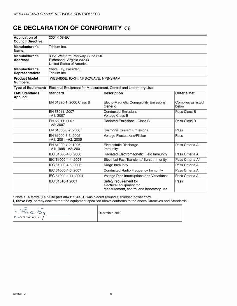
CE DECLARATION OF CONFORMITY
* Note 1, A ferrite (Fair-Rite part #0431164181) was placed around a shielded power cord.I, Steve Fey, hereby declare that the equipment specified above conforms to the above Directives and Standards.
Application of Council Directive:
2004-108-EC
Manufacturer’s Name:
Tridium Inc.
Manufacturer’s Address:
3951 Westerre Parkway, Suite 350Richmond, Virginia 23233United States of America
Manufacturer’s Representative:
Steve Fey, PresidentTridium Inc.
Product Model Numbers:
WEB-600E, IO-34, NPB-ZWAVE, NPB-SRAM
Type of Equipment: Electrical Equipment for Measurement, Control and Laboratory Use
EMS Standards Applied:
Standard Description Criteria Met
EN 61326-1: 2006 Class B Electo-Magnetic Compaibility Emissions, Generic
Complies as listed below
EN 55011: 2007 +A1: 2007
Conducted Emissions - Voltage Class B
Pass Class B
EN 55011: 2007 +A2: 2007
Radiated Emissions - Class B Pass Class B
EN 61000-3-2: 2006 Harmonic Current Emissions Pass
EN 61000-3-3: 2005+A1: 2001 +A2: 2005
Voltage Fluctuations/Flicker Pass
EN 61000-4-2: 1995+A1: 1998 +A2: 2001
Electostatic Discharge Immunity
Pass Criteria A
IEC 61000-4-3: 2006 Radiated Electromagnetic Field Immunity Pass Criteria A
IEC 61000-4-4: 2004 Electrical Fast Transient / Burst Immunity Pass Criteria A*
IEC 61000-4-5: 2006 Surge Immunity Pass Criteria A
IEC 61000-4-6: 2007 Conducted Radio Frequency Immunity Pass Criteria A
IEC 61000-4-11: 2004 Voltage Dips Interruptions and Variations Pass Criteria A
IEC 61010-1:2001 Safety requirement for electrical equipment for measurement, control and laboratory use
Pass
December, 2010

WEB-600E AND CP-600E NETWORK CONTROLLERS
19 62-0433—01
TAB MOUNTING DIMENSIONSMeasurements are in inches and (mm). Note that DIN mounting is recommended over tab mounting. See Fig. 1.
Fig. 10. Tab mounting dimentions.1-64DIA.(4)
3-1/4(83)
WEB-600E IO-16-H IO-16-H OR NPB-PWR-H
NOTE:DOCUMENT MAY NOT SHOW DIMENSIONS TO SCALE.VERIFY ALL MEASUREMENTS BEFORE DRILLING.
ELECTRONIC AND PRINTED VERSIONS OF THIS
DIN MOUNTING IS RECOMMENDED OVER TAB MOUNTING.SEE FIG. 1.
WEB-600E
NPB-PWR-H,NPB-PWR-UN-H,
OR IO-16-H
NOTE: DISTANCE BETWEEN CENTER OF TABS FROM ONE UNIT TO ANOTHER UNIT.
TIP: IF MOUNTING ACCESSORY MODULES, FUTURE REMOVAL/REPLACEMENT OF THE CONTROLLER IS SIMPLIFIED IF YOU DO NOT INSTALL SCREWS IN THE “ACCESSORY MODULE SIDE” TABS OF THE CONTROLLER (SEE ABOVE).
ACCESSORYMODULESIDE TABS
M33924
2-1/2(64)
6-23/32 (171)
4(102)
3-3/4 (95)
2-1/2(64)
6-23/32 (171) 3-1/4(83)
3-31/64(89)

WEB-600E AND CP-600E NETWORK CONTROLLERS
Automation and Control SolutionsHoneywell International Inc.
1985 Douglas Drive North
Golden Valley, MN 55422
customer.honeywell.com
® U.S. Registered Trademark© 2012 Honeywell International Inc.62-0433—01 M.S. 11-12 Printed in United States
By using this Honeywell literature, you agree that Honeywell will have no liability for any damages arising out of your use or modification to, the literature. You will defend and indemnify Honeywell, its affiliates and subsidiaries, from and against any liability, cost, or damages, including attorneys’ fees, arising out of, or resulting from, any modification to the literature by you.