Embed Size (px)
Citation preview

RAC6155 IndustrialComputers
Product Data andInstallation Instructions

Publication 6155-IN001C-EN-P
Solid state equipment has operational characteristics differing from those ofelectromechanical equipment. "Safety Guidelines for the Application,Installation, and Maintenance of Solid State Controls" (Publication SGI-1.1)describes some important differences between solid state equipment and hard-wired electromechanical devices. Because of this difference, and because ofthe wide variety of uses for solid state equipment, all persons responsible forapplying this equipment must satisfy themselves that each intended applicationof this equipment is acceptable.
In no event will Rockwell Automation be responsible or liable for indirect orconsequential damages resulting from the use or application of this equipment.
The examples and diagrams in this manual are included solely for illustrativepurposes. Because of the many variables and requirements associated with anyparticular installation, Rockwell Automation cannot assume responsibility orliability for actual use based on the examples and diagrams.
No patent liability is assumed by Rockwell Automation with respect to use ofthe information, circuits, equipment, or software described in this manual.
Reproduction of the contents of this manual, in whole or in part, withoutwritten permission of Rockwell Automation is prohibited.
Throughout this manual, we use notes to make you aware of safetyconsiderations.
Important: Identifies information that is especially important forsuccessful application and understanding of the product.
European Union Compliance
The 6155 Computer meets the European Union Directive requirements wheninstalled within the European Union or EEA regions and has the CE mark. Acopy of the Declaration of Conformity is available at the Rockwell Automation / Allen-Bradley Internet site: www.ab.com
Important UserInformation
ATTENTION: Identifies information about practices orcircumstances that can lead to personal injury or death,property damage, or economic loss.
ATTENTION: The 6155 Computer is intended tooperate in an industrial or control room environment,which utilizes some form of power isolation from thepublic low voltage mains. Some 6155 Computerconfigurations may not comply with the EN 61000-3-2Harmonic Emissions standard as specified by the EMCDirective of the European Union. Obtain permissionfrom the local power authority before connecting any6155 Computer configuration that draws more than 75watts of AC power directly from the public mains.

Publication 6155-IN001C-EN-P
Table of Contents
Using this Manual PrefaceWho Should Use This Manual . . . . . . . . . . . . . . . . . . . . . . . . . . . . . . . . . .P-1Purpose of this Manual . . . . . . . . . . . . . . . . . . . . . . . . . . . . . . . . . . . . . . .P-1Manual Conventions . . . . . . . . . . . . . . . . . . . . . . . . . . . . . . . . . . . . . . . . .P-1Allen-Bradley Support . . . . . . . . . . . . . . . . . . . . . . . . . . . . . . . . . . . . . . . .P-2
Computer Features Chapter 1Description . . . . . . . . . . . . . . . . . . . . . . . . . . . . . . . . . . . . . . . . . . . . . . . .1-1Packing List . . . . . . . . . . . . . . . . . . . . . . . . . . . . . . . . . . . . . . . . . . . . . . . .1-1Physical Dimensions . . . . . . . . . . . . . . . . . . . . . . . . . . . . . . . . . . . . . . . . .1-2
Installation Chapter 2Chapter Objective . . . . . . . . . . . . . . . . . . . . . . . . . . . . . . . . . . . . . . . . . . .2-1European Union Compliance . . . . . . . . . . . . . . . . . . . . . . . . . . . . . . . . . . .2-1Environmental Considerations . . . . . . . . . . . . . . . . . . . . . . . . . . . . . . . . . .2-1Rack Mounting . . . . . . . . . . . . . . . . . . . . . . . . . . . . . . . . . . . . . . . . . . . . .2-1Connecting AC Power . . . . . . . . . . . . . . . . . . . . . . . . . . . . . . . . . . . . . . . .2-2Installing Cables . . . . . . . . . . . . . . . . . . . . . . . . . . . . . . . . . . . . . . . . . . . .2-3Opening the Computer Chassis . . . . . . . . . . . . . . . . . . . . . . . . . . . . . . . . .2-3
Initial Operation and Setup Chapter 3Chapter Objective . . . . . . . . . . . . . . . . . . . . . . . . . . . . . . . . . . . . . . . . . . .3-1Operating Recommendations . . . . . . . . . . . . . . . . . . . . . . . . . . . . . . . . . . .3-1Operator Access . . . . . . . . . . . . . . . . . . . . . . . . . . . . . . . . . . . . . . . . . . . .3-1System Checkout . . . . . . . . . . . . . . . . . . . . . . . . . . . . . . . . . . . . . . . . . . .3-2System Reset . . . . . . . . . . . . . . . . . . . . . . . . . . . . . . . . . . . . . . . . . . . . . .3-2Using USB . . . . . . . . . . . . . . . . . . . . . . . . . . . . . . . . . . . . . . . . . . . . . . . .3-2
Installing/Removing Memory Modules Chapter 4
Chapter Objective . . . . . . . . . . . . . . . . . . . . . . . . . . . . . . . . . . . . . . . . . . .4-1Available RAM Memory . . . . . . . . . . . . . . . . . . . . . . . . . . . . . . . . . . . . . . .4-1Guidelines for Adding/Removing Memory . . . . . . . . . . . . . . . . . . . . . . . . . .4-1Safety Precautions . . . . . . . . . . . . . . . . . . . . . . . . . . . . . . . . . . . . . . . . . .4-2Adding/Removing Memory Modules . . . . . . . . . . . . . . . . . . . . . . . . . . . . . .4-2
System Troubleshooting Chapter 5Chapter Objective . . . . . . . . . . . . . . . . . . . . . . . . . . . . . . . . . . . . . . . . . . .5-1Troubleshooting Procedures . . . . . . . . . . . . . . . . . . . . . . . . . . . . . . . . . . .5-1Troubleshooting Check Lists . . . . . . . . . . . . . . . . . . . . . . . . . . . . . . . . . . .5-2

Maintenance Chapter 6Chapter Objective . . . . . . . . . . . . . . . . . . . . . . . . . . . . . . . . . . . . . . . . . . .6-1Cleaning the Chassis Fan Filters . . . . . . . . . . . . . . . . . . . . . . . . . . . . . . . .6-1Replacing the Battery . . . . . . . . . . . . . . . . . . . . . . . . . . . . . . . . . . . . . . . .6-2Preparation for Shipment . . . . . . . . . . . . . . . . . . . . . . . . . . . . . . . . . . . . . .6-2Replacement Parts . . . . . . . . . . . . . . . . . . . . . . . . . . . . . . . . . . . . . . . . . .6-3
Specifications Appendix A
toc-ii Bulletin 6155 Industrial Computer
Publication 6155-IN001C-EN-P

Manual Conventions
Purpose of this Manual
Publication 6155-IN001C-EN-P
Preface
Using this Manual
Read this preface to familiarize yourself with the rest of the manual.The preface covers the following topics:
• Who should use this manual
• The purpose of the manual
• Conventions used in this manual
• Allen-Bradley support
Use this manual if you are responsible for installing, using ortroubleshooting the Bulletin 6155 Industrial Computer.
This manual is a user guide for the Bulletin 6155 Industrial Computer.It gives an overview of the system and describes procedures you use to:
• Install the 6155 Computer in an enclosure
• Install and remove system components
• Run the system
• Troubleshoot the system
The following conventions are used throughout this manual:
• Bulleted lists such as this one provide information, not proceduralsteps.
• Numbered lists provide sequential steps or hierarchical information.
Who Should Use This Manual

Publication 6155-IN001C-EN-P
P-2 Bulletin 6155 Industrial Computer
Allen-Bradley offers support services worldwide, with over 75Sales/Support Offices, 512 authorized Distributors and 260 authorizedSystems Integrators located throughout the United States alone, plusAllen-Bradley representatives in every major country in the world.
Local Product Support
Contact your local Allen-Bradley representative for:
• Sales and order support
• Product technical training
• Warranty support
• Support service agreements
Technical Product Assistance
If you need to contact Allen-Bradley for technical assistance, pleasereview the information in the System Troubleshooting chapter first.Then call your local Allen-Bradley representative or contact Allen-Bradley technical support at (440) 646-5800.
For additional product information and a description of the technicalservices available, visit the Rockwell Automation/Allen-BradleyInternet site at http://www.ab.com.
Allen-Bradley Support

Packing List
Publication 6155-IN001C-EN-P
Chapter 1
Computer Features
The Bulletin 6155 Industrial Computer features:
• Variety of CPU types and speeds
• Rack mount or benchtop
• Active motherboard computer
• Many options for enhancement and expansion
The Bulletin 6155 Industrial Computer is shipped with the followingitems:
• Industrial Computer
• 1.82 m (6ft.) AC Power Cord (optional)
• Industrial computers Product Data & Installation manual
• CPU/Processor Manual
• Software diskettes for major components
• Optional accessory items and manuals
Note: Check your shipment against the packing list in theshipping carton.
Description

1-2 Bulletin 6155 Industrial Computer
Figure 1Dimensions of Bulletin 6155 Industrial Computer (Rackmount / Benchtop)
Note: Be sure to allow at least 76.2 mm (3.00 in.) depth clearancefor cable connections and air flow.
Physical Dimensions
Publication 6155-IN001C-EN-P

Rack Mounting
EnvironmentalConsiderations
European UnionCompliance
Publication 6155-IN001C-EN-P
Chapter 2
Installation
This chapter describes installation of the 6155 Computer.
The 6155 Computer meets the European Union Directive requirementswhen installed within the European Union or EEA regions and has theCE mark. A copy of the Declaration of Conformity is available at theRockwell Automation / Allen-Bradley Internet site: www.ab.com
For proper cooling, the computer requires a minimum free air space of76mm (3 in.) behind, 51mm (2in.) above and below, and 25mm (1 in.)on the sides of the chassis. The computer is equipped with fans to helpensure proper cooling.
The computer can be installed in a rack cabinet that conforms to EIAstandards for equipment with 19 in. wide panels. The cabinet must betall enough to accommodate the computer's height and deep enough toaccommodate the unit's depth, while providing rear clearance forcabling and air flow. A cabinet with a depth of 61 cm (24 in.) issufficient.
The computer is designed to be supported by rack slides or to be placedon a shelf. The front flanges of the computer are intended tohorizontally secure the unit to the rack cabinet's front mounting rails.
ATTENTION: The 6155 Computer is intended tooperate in an industrial or control room environment,which utilizes some form of power isolation from thepublic low voltage mains. Some 6155 Computerconfigurations may not comply with the EN 61000-3-2Harmonic Emissions standard as specified by the EMCDirective of the European Union. Obtain permissionfrom the local power authority before connecting any6155 Computer configuration that draws more than 75watts of AC power directly to the public mains.
Chapter Objective

Publication 6155-IN001C-EN-P
2-2 Bulletin 6155 Industrial Computer
To install a Bulletin 6155 computer in your rack:
1. Refer to the physical dimension drawings for your unit (Figure 1,page 1-2) to confirm that there is adequate space behind the panelwhere the unit is mounted. Remember to allow extra space for aircirculation.
2. Install the rack slides in the rack cabinet.
3. Carefully remove the computer from its packaging.
4. Attach the rack slides to the unit, and align to the mating slide insidethe cabinet.
5. Insert the computer in the rack cabinet from the front of the cabinet.
Tip: It will be easier to install the computer if you support itwith a shelf or other support adjusted to the appropriateheight.
6. Horizontally secure the computer to the front mounting rails of therack cabinet.
The computer requires a single-phase power supply providing 90-132VAC or 180-264V AC at 47 to 63 Hz. Power must be available at thethree-pin AC input receptacle situated in the rear of the unit.
To connect AC power to the computer:
1. Turn off the main switch or breaker.
2. Use the GND point on the rear panel of the computer to establish achassis to earth ground connection. Secure one end of a ground strapto the GND point. Connect the other end of the ground strap toground. The ground terminals are M5 screws.
3. Connect the plug end of the AC power cord to the mating connectoron the rear of the computer.
4. Connect the plug end of the AC cord to the main outlet.
5. Restore AC power to the outlet.
Connecting AC Power

Opening the Computer Chassis
Bulletin 6155 Industrial Computer 2-3
Publication 6155-IN001C-EN-P
You will need to connect a number of cables at the rear of the unitbefore your Industrial Computer will function. This section describesthe cable connections you will need to make. While installing cables, besure to keep the following points in mind.
• Connect the cables according to the options in your IndustrialComputer.
• Route and secure the cables. In cases where the cable crosses a doorhinge, be sure to leave enough excess cable for a loose fit in all doorpositions.
• Coil and secure any extra cable length in a convenient location.
• Refer to the illustrations provided for help in routing and connectingthe cables required to use your Industrial Computer.
You may have to open the computer chassis to install a card or for someother reason.
1. Remove the two screws at the back of the top cover of the unit.
2. Slide the cover straight back at least 6mm (0.25 in.) and then lift off.
Screws
Installing Cables

2-4 Bulletin 6155 Industrial Computer
Publication 6155-IN001C-EN-P

Operator Access
OperatingRecommendations
Chapter 3
Initial Operation and Setup
This chapter provides information on:
• Operating recommendations
• Boot-up sequence
• System reset and power on/off buttons
• Universal Serial Bus (USB)
We recommend the following operating guidelines for the 6155Computer:
• Avoid turning the system on and off frequently.
• Never turn the system off when the hard drive indicator light isilluminated.
• Always use the proper power down procedures as required by youroperating system, such as the Shut Down command in MicrosoftWindows.
• Do not turn off the computer until a message appears telling you thatit is safe to do so.
• Do not operate the 6155 Computer with covers removed. Anelectrical shock hazard exists. In addition, removing the covers willdisrupt air flow and may result in overheating. All covers arerequired to maintain EMI shield.
Access to components inside the chassis is restricted to authorized andproperly trained personnel.
ATTENTION: After shutting the system off, do notmove the computer or turn it back on again until the harddrive has come to a complete stop (takes about 30seconds).If you are using an external monitor, turn on the monitorfirst.
ATTENTION: The DVD-ROM contains a laser system,which is a source of low-level X-ray radiation. To ensureproper use of this product, please read this instructionmanual carefully and retain for future reference. Shouldthe unit ever require maintenance, contact an authorizedservice location.
Use of controls, adjustments or the performance ofprocedures other than those specified may result inhazardous radiation exposure.
To prevent direct exposure to laser beam, do not open theenclosure.
Chapter Objective

Using USB
System Reset
To boot up the system:
1. Apply power to the computer. The 6155 Computer performs aPower On Self Test (POST) in which it tests the processor board,memory, keyboard, and certain peripheral devices.
2. The 6155 Computer displays the progress of the POST andinitialization of accessory devices.
3. If your system does not boot up, or you notice other problems, referto Chapter 5, System Troubleshooting.
4. The 6155 Computer will then display the startup dialogs for theoperating system that has been installed. If no software is installed,the following prompt is displayed:
Insert bootable media in the appropriatedrive.
To reset the 6155 Computer, press [Ctrl] [Alt] [Delete] on an attachedkeyboard and follow the operating system instructions.
After resetting, the 6155 Computer will begin the Power On Self Test(POST). During reset, the 6155 Computer:
• Clears RAM
• Starts the POST
• Initializes peripheral devices, such as drives and printers
• Loads the operating system (if installed)
The 6155 Computer has two USB connectors.
The Universal Serial Bus (USB) is an external bus standard thatsupports data transfer rates of 12Mbps (12 million bits per second). Asingle USB port can connect multiple peripheral devices, such as mice,modems, and keyboards. USB also supports Plug-and-Play installationand hot plugging.
For more information on installing or using USB, refer to thedocumentation for your USB peripheral device.
Note: Many USB devices only work with Windows 98 orWindows 2000, because these operating systems havenative USB drivers. Make sure the selected USB peripheralhas software drivers available for your target operatingsystem.
3-2 Bulletin 6155 Industrial Computer
Publication 6155-IN001C-EN-P
System Checkout

Guidelines forAdding/RemovingMemory
Available RAM Memory
Publication 6155-IN001C-EN-P
Chapter 4
Installing/Removing MemoryModules
This chapter describes how to add RAM Memory to the 6155 Computerprocessor board. Topics include:
• Available RAM memory
• Guidelines for adding/removing memory modules
• How to add/remove memory modules to processor board
The 6155 Computer has three 168-pin sockets supporting a single ordouble-sided Dual In-Line Memory Module (DIMM):
Memory Module Catalog Number64MB SDRAM DIMM 6189-DIMM64128MB SDRAM DIMM 6189-DIMM128256MB SDRAM DIMM 6189-1DIMM256
Note: If you use any type of memory module other than aqualified Allen-Bradley part, you may encounter problems.
When adding memory to the 6155 Computer, follow these guidelines:
• Use only a standard, unbuffered 168-pin DIMM that conforms toboth PC-100 and Serial Presence Detect (SPD) compliance industrystandards.
• Use only Synchronous Dynamic Random Access Memory(SDRAM) type DIMMs.
• BIOS automatically detects memory size and type (i.e., SDRAM vs.EDO). It does not detect parity, however, so this must be manuallyconfigured by the end-user in BIOS Setup. The 6155 Computerships with ECC-type memory, and the Memory Parity Check featurein BIOS Setup is programmed to "ECC" by default.
• If a non-ECC DIMM is installed, the Memory Parity Check in BIOSSetup must be changed/saved to "Disabled". The system will fail toboot if ECC is enabled in Setup with a non-ECC DIMM installed.
• Use only gold-plated lead DIMMs.
Chapter Objective

Publication 6155-IN001C-EN-P
4-2 Bulletin 6155 Industrial Computer
Internal 6155 Computer components may be damaged by ElectrostaticDischarge (ESD). Make sure you wear a grounding strap wheneverhandling circuit boards, memory modules or other internal components.
Also observe the following precautions:
• Always handle the memory cards by the ends not by the memorymodule contacts.
• Store memory in a sealed anti-static bag when it is not installed.
• Never install or remove memory with the power turned on.
This section gives instructions on how to change an installed memorymodule in the 6155 Computer processor board.
To add or remove memory:
1. Disconnect power from the 6155 Computer.
2. Remove the top cover of the 6155 Computer. Refer to procedures inChapter 2 for details on how to remove the top access cover.
3. Remove the existing DIMM module from the CPU card by pressingdown on the retaining latch. The DIMM module is located at thetop of the CPU card, just below the top access cover.
4. To install a new DIMM, hold the module only by the edges as youremove it from its anti-static package.
5. Position the DIMM so that the small notches in the bottom edge ofthe DIMM align with the notches in the DIMM socket on the CPUcard. The retaining latch should be fully disengaged whenattempting to install a DIMM.
6. Press down firmly and uniformly on the DIMM to seat it in thesocket. The latch should engage in the DIMM locking slot to securethe part in place.
7. Reinstall the top access cover.
ATTENTION: Wear a wrist strap (well grounded) andperform work in a static-safe environment. Electrostaticdischarge can damage the 6155 Computer andcomponents.
Adding/RemovingMemory Modules
ATTENTION: Disconnect all power from the 6155Computer before adding/removing components. Failureto disconnect power could result in severe electricalshock or damage to the 6155 Computer.
Safety Precautions

Publication 6155-IN001C-EN-P
TroubleshootingProcedures
Chapter 5
System Troubleshooting
This chapter describes the most common operating problems, theprobable causes, and recommended corrective actions including:
• Troubleshooting procedure
• Troubleshooting checklists
• Boot-up error messages
• General error and information messages
To help identify and isolate a problem, we recommend that you do thefollowing when a problem occurs:
1. Disconnect power to the 6155 Computer.
2. Disconnect any peripheral devices such as printer or scanner.
3. Check the video connections if using an external monitor.
4. If the system normally boots from the hard drive, make sure there isnot a diskette in the floppy drive.
5. Apply power and observe the LEDs on the front panel (if present).Make sure the power on indicator is illuminated.
6. Monitor the Power On Self Test (POST). One of 3 events will occur:
• The 6155 Computer will complete the boot-up process.
• An error message will occur indicating a non-fatal fault. Youmay have to acknowledge the message before the boot-upprocess is allowed.
• The boot-up process will terminate (fatal error).
7. If the system boots up, isolate the problem by connecting peripheraldevices one at a time until the problem occurs. If the problem is with aspecific software package or driver, you may want to re-install thesoftware.
8. If there is a problem not related specifically to a software installationor peripheral device, refer to the following troubleshooting checklists.
Chapter Objective

The following are checklists of items that you may have overlooked.
If you are having problems during boot-up:
� Are all connections secure?
� Are the device drivers installed?
� Are the jumpers on any add-in boards correctly positioned?
� Is the hard drive formatted and set up in the BIOS?
� Is the RAM memory (DIMM) properly installed? You may want tore-install it to ensure a good connection.
� Is the EIDE cable from the hard drive properly connected? You maywant to see if the system will boot from a floppy diskette.
� Is BIOS properly configured?
If there is a problem after boot-up:
� If you are running a software package, re-install the software.
� If the problem is intermittent, you may have a loose connection.Check all connections including any ISA/PCI/AGP cards. Checkthat the memory module (DIMM) is fully installed.
� Does your system have a computer virus? Run anti-virus software.
� Try clearing CMOS by removing and reinstalling the battery andrunning BIOS Setup.
� Although the 6155 Computer has a regulated and protected powersupply, a transient voltage in the power line or peripheral cable maycause a flickering display, unexpected reboots, or a locked upsystem. If so, exit the application and start over.
� Is the EIDE cable from the hard drive properly connected? You maywant to see if the system will boot from a floppy drive.
� Is the system overheating? Look at the diagnostics light on the frontpanel display (if present). Verify that the chassis fan is working andthe filter is clean.
5-2 Bulletin 6155 Industrial Computer
Publication 6155-IN001C-EN-P
Troubleshooting Check Lists

If there is a problem running new software:
� Does the software have a hardware requirement that is not present?
� Are you using an authorized copy of the software? Some copies ofsoftware will not work without proper activation.
� Did the software install correctly? Re-install the software.
� Are you following the software's instructions? Refer to the softwarevendor's user manual.
� If the new software installed system software (DLL files) or devicedrivers, reapply the current Service Pack (release) of the operatingsystem. Refer to Chapter 3, Initial Operation and Setup.
If there is a problem with an add-in board:
� Is the board installed and configured correctly? Recheck jumper andother configuration settings.
� Are any cables correctly installed?
If the board is an ISA board (not Plug and Play) refer to the followingsuggestions:
� If the board uses an interrupt, run BIOS Setup and set the interruptused by the ISA board to Reserved. In the advanced BIOS menu,select the PCI Configuration PCI/PNP IRQ subscreen and thenreserve the IRQ of the card.
� If the board uses memory between 80000H and 9FFFFH, run BIOSsetup and set conventional memory to 512K.
� If the board uses memory between C8000H and DFFFH, run BIOSsetup and reserve the appropriate memory space.
If characters are not displayed on a monitor:
� Is the monitor functioning properly?
� Is the video cable properly installed?
� Check that selected character color is not set the same as thebackground color.
� Is the video driver properly installed?
Bulletin 6155 Industrial Computer 5-3
Publication 6155-IN001C-EN-P

If the hard drive active LED indicator does not come on when the harddrive is being accessed:
� Check the EIDE cable connections to the drive.
� Check BIOS Setup for proper configuration. Is drive enabled?
� Check the connections on the I/O board.
� Reboot the 6155 Computer.
If the Power On LED indicator does not come on:
� Check the front panel connector on the processor board.
� Check the power cord.
� Check the connections on the I/O board.
5-4 Bulletin 6155 Industrial Computer
Publication 6155-IN001C-EN-P

Cleaning the Chassis Fan Filters
Publication 6155-IN001C-EN-P
Chapter 6
Maintenance
This chapter describes routine maintenance procedures.
Clean the chassis fan filters at least once a month under normalconditions. You may need to clean the filters more frequently if the6155 Computer is located in an area with high levels of dust.
Important: You must clean the chassis fan filters properly to maintainthe thermal integrity of the 6155 Computer.
To clean the chassis fan filters:
1. Disconnect all power from the 6155 Computer.
2. Snap out the filter and retainer.
3. Remove the filter pad and clean the filter and filter pad withsoap and water and allow it to dry before installing.
4. Press down on the filter retainer until it snaps firmly into place onthe fan.
ATTENTION: Disconnect all power from the 6155Computer before removing components. Failure todisconnect power could result in severe electrical shockor damage to the 6155 Computer.
Front Fan Filterand Retainer
Rear Fan Filterand Retainer
Chapter Objective

The 6155 Computer contains a battery to maintain the CMOS settingsand real-time clock. The battery is located in a battery holder on themotherboard. Replace this battery as needed with an identicalreplacement.
The battery life is dependent on the amount of on-time per week.Estimated life of the battery is listed below:
On-Time Expected Battery Life0 hours/week 4 years40 hours/week 5.5 years80 hours/week 7 years
If it is necessary to ship the computer from one site to another, it shouldbe removed from the rack cabinet in which it has been installed.Whenever possible, the computer should be repacked in its originalshipping carton.
To remove the computer from the rack cabinet, reverse the installationprocedures given previously in this manual.
Note: Be careful to remove the ground wire before removing thecomputer from the rack cabinet.
6-2 Bulletin 6155 Industrial Computer
Publication 6155-IN001C-EN-P
Preparation for Shipment
ATTENTION: Never try to ship the IndustrialComputer while it is mounted in a rack. Doing so couldresult in damage to the rack or the Industrial Computer.
Replacing the Battery
ATTENTION: There is a danger of explosion if thebattery is incorrectly replaced. Replace only with thesame or equivalent type recommended by themanufacturer. Dispose of used batteries according to themanufacturer's instructions.
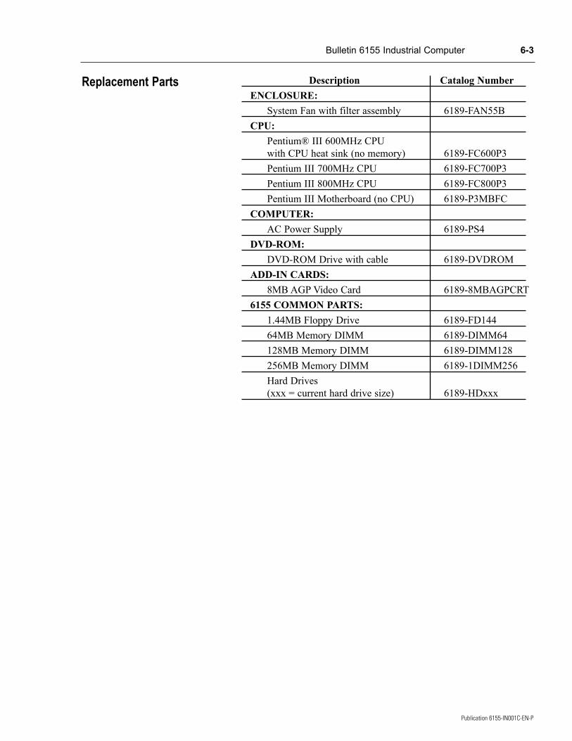
Description Catalog NumberENCLOSURE:
System Fan with filter assembly 6189-FAN55BCPU:
Pentium® III 600MHz CPUwith CPU heat sink (no memory) 6189-FC600P3Pentium III 700MHz CPU 6189-FC700P3Pentium III 800MHz CPU 6189-FC800P3Pentium III Motherboard (no CPU) 6189-P3MBFC
COMPUTER:AC Power Supply 6189-PS4
DVD-ROM:DVD-ROM Drive with cable 6189-DVDROM
ADD-IN CARDS:8MB AGP Video Card 6189-8MBAGPCRT
6155 COMMON PARTS:1.44MB Floppy Drive 6189-FD14464MB Memory DIMM 6189-DIMM64128MB Memory DIMM 6189-DIMM128256MB Memory DIMM 6189-1DIMM256Hard Drives (xxx = current hard drive size) 6189-HDxxx
Bulletin 6155 Industrial Computer 6-3
Publication 6155-IN001C-EN-P
Replacement Parts

6-4 Bulletin 6155 Industrial Computer
Publication 6155-IN001C-EN-P

Publication 6155-IN001C-EN-P
Appendix A
Specifications
Processor/MemoryProcessor/Speed (MHz)* Pentium III 600 MHz, 700 MHz,
800 MHzMemory Options 32M, 64M, 128M, 256M, 512MSystemSystem Bus Architecture 32-bit PCI/ 16-bit ISAExpansion Slots Pentium Active Motherboard:
1 AGP, 3 full length PCI, 2 full length ISA, 1 full length shared PCI/ISA
Serial Ports, Standard 2Parallel Ports, Standard 1USB Ports 2 on Pentium CPU boardOperating Systems MS-DOS®, Windows® 98,
Windows NT®, Windows 2000
Network Support PCI Ethernet cardMass StorageInternal Drive Bays (6) rackmount/benchtop:
- (2) 3.5" hard drive mounting locations
- (3) 5.25" device bays- (1) 3.5" device bay
Diskette Drive 3.5 inch, 1.44 Mbyte EIDEHard Disk drives* Standard (currently 30+ GB
3.5 in. EIDE)
Large (currently 60+ GB 3.5 in. EIDE)
Operator InputStandard Keyboard Interface Front panel PS/2, Rear panel PS/2Video Controller 8MB AGPCables Power cord (optional)
* Contact factory for latest options

Environmental (specifications assume standard configuration, excluding diskette drive)Temperature
Operating +5 °C to +45°C Storage -30°C to +60°C
Relative Humidity 8% to 80% non-condensingAltitude
Operating To 10,000 ft. (3,000m)Non-Operating To 40,000 ft. (12,000m)
VibrationOperating 0.1in. p-p, 5-14 Hz sine;
1.0g peak, 14-500 Hz sineNon-Operating 0.1 in. p-p, 5-14 Hz sine;
2.0g peak, 14-500 Hz sineShock
Operating 10g (1/2 sine, 11 msec)Non-operating 30g (1/2 sine, 11 msec)
ElectricalLine voltage 90-132V AC,
180-264V AC auto-switchingLine Frequency 47-63 HzPower Consumption 150W typical, 300W max.SafetyElectric Shock, Fire UL / C-UL 1950 listed
EN60950X-Ray Emissions N/APhysicalBulletin 6155 Dimensions Refer to Figure 1 (page 1-2)Net Weight 35 lb. (16 kg)Agency Approval CE
A-2 Bulletin 6155 Industrial Computer
Publication 6155-IN001C-EN-P

Pentium is a registered trademark of Intel Corporation.MS-DOS, Windows and Windows NT are registered trademarks of Microsoft Corporation.
Publication 6155-IN001C-EN-P – January 2002 41061-188-01(3)Supersedes Publication 6155-IN001B-EN-P – August 2001 Copyright © 2002 Rockwell Automation. All rights reserved. Printed in USA.