Embed Size (px)
Citation preview

613GC Cut-Off SawShop Manual

TITLE613GC SHOP MANUAL
�Copyright © 2005 ICS, Blount Inc.
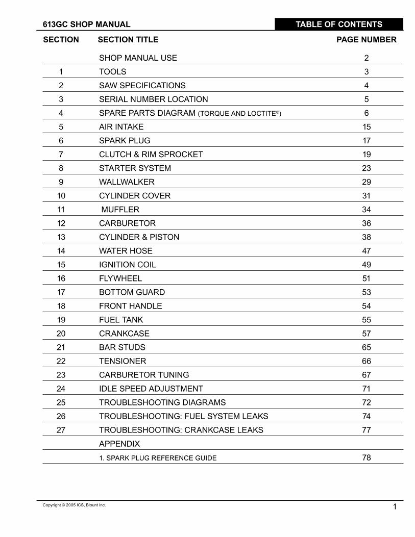
TABLE OF CONTENTS
SHOP MANUAL USE 2
� TOOLS 3
2 SAW SPECIFICATIONS 4
3 SERIAL NUMBER LOCATION 5
4 SPARE PARTS DIAGRAM (TORQUE AND LOCTITE®) 6
5 AIR INTAKE �5
6 SPARK PLUG �7
7 CLUTCH & RIM SPROCKET �9
8 STARTER SYSTEM 23
9 WALLWALKER 29
�0 CYLINDER COVER 3�
�� MUFFLER 34
�2 CARBURETOR 36
�3 CYLINDER & PISTON 38
�4 WATER HOSE 47
�5 IGNITION COIL 49
�6 FLYWHEEL 5�
�7 BOTTOM GUARD 53
�8 FRONT HANDLE 54
�9 FUEL TANK 55
20 CRANKCASE 57
2� BAR STUDS 65
22 TENSIONER 66
23 CARBURETOR TUNING 67
24 IDLE SPEED ADJUSTMENT 7�
25 TROUBLESHOOTING DIAGRAMS 72
26 TROUBLESHOOTING: FUEL SYSTEM LEAKS 74
27 TROUBLESHOOTING: CRANKCASE LEAKS 77
APPENDIX
�. SPARK PLUG REFERENCE GUIDE 78
SECTION SECTION TITLE PAGE NUMBER

TITLE 613GC SHOP MANUAL
2 Copyright © 2005 ICS, Blount Inc.
SHOP MANUAL USE
Shop Manual Use
This manual contains all the technical information necessary for carrying out repairs on the 6�3GC cut-off saw. For safe, efficient work, it is of prime importance that the values indicated be adhered to. Routine periodic maintenance is covered in the operator’s manual included with each cut-off saw.
General Shop Rules
• Always use the right tools for the job, otherwise components may be damaged.
• Use a plastic dead blow mallet to separate parts attached solidly to each other.
• Mark mating parts as a reassembly reference.
• Keep component parts together as a group. Assemble screws and nuts into appropriate subgroups.
• When reassembling, clean all parts carefully, lubricate moving parts and replace all oil seals, orings, gaskets, washers and self-locking nuts.
• For best results, use only original ICS® replacement parts.
General Recommendations
• Some procedures in this manual require the use of special tools. A complete tool kit for ICS® cut-off saws is available from ICS®.
• Detailed carburetor maintenance and overhaul information is available in Walbro’s Diaphragm Carburetor Service Manual. Walbro can be contacted at http:\\www.walbro.com or by calling �.989.872.2�3�.
613GC SHOP MANUAL
3Copyright © 2005 ICS, Blount Inc.
1. TOOLS
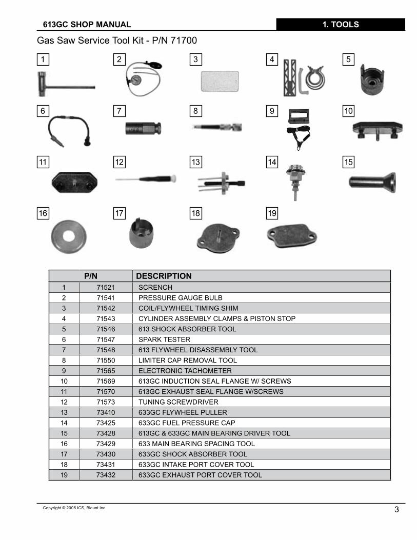
P/N DESCRIPTION� 7�52� SCRENCH 2 7�54� PRESSURE GAUGE BULB3 7�542 COIL/FLYWHEEL TIMING SHIM4 7�543 CYLINDER ASSEMBLY CLAMPS & PISTON STOP5 7�546 6�3 SHOCK ABSORBER TOOL6 7�547 SPARK TESTER7 7�548 6�3 FLYWHEEL DISASSEMBLY TOOL8 7�550 LIMITER CAP REMOVAL TOOL9 7�565 ELECTRONIC TACHOMETER�0 7�569 6�3GC INDUCTION SEAL FLANGE W/ SCREWS�� 7�570 6�3GC EXHAUST SEAL FLANGE W/SCREWS�2 7�573 TUNING SCREWDRIVER�3 734�0 633GC FLYWHEEL PULLER�4 73425 633GC FUEL PRESSURE CAP�5 73428 6�3GC & 633GC MAIN BEARING DRIVER TOOL�6 73429 633 MAIN BEARING SPACING TOOL�7 73430 633GC SHOCK ABSORBER TOOL�8 7343� 633GC INTAKE PORT COVER TOOL�9 73432 633GC EXHAUST PORT COVER TOOL
Gas Saw Service Tool Kit - P/N 7�700
� 2 3 4 5
6 7 8 9 �0
�� �2 �3 �4 �5
�6 �7 �8 �9
613GC SHOP MANUAL
4 Copyright © 2005 ICS, Blount Inc.
2. SPECIFICATIONS
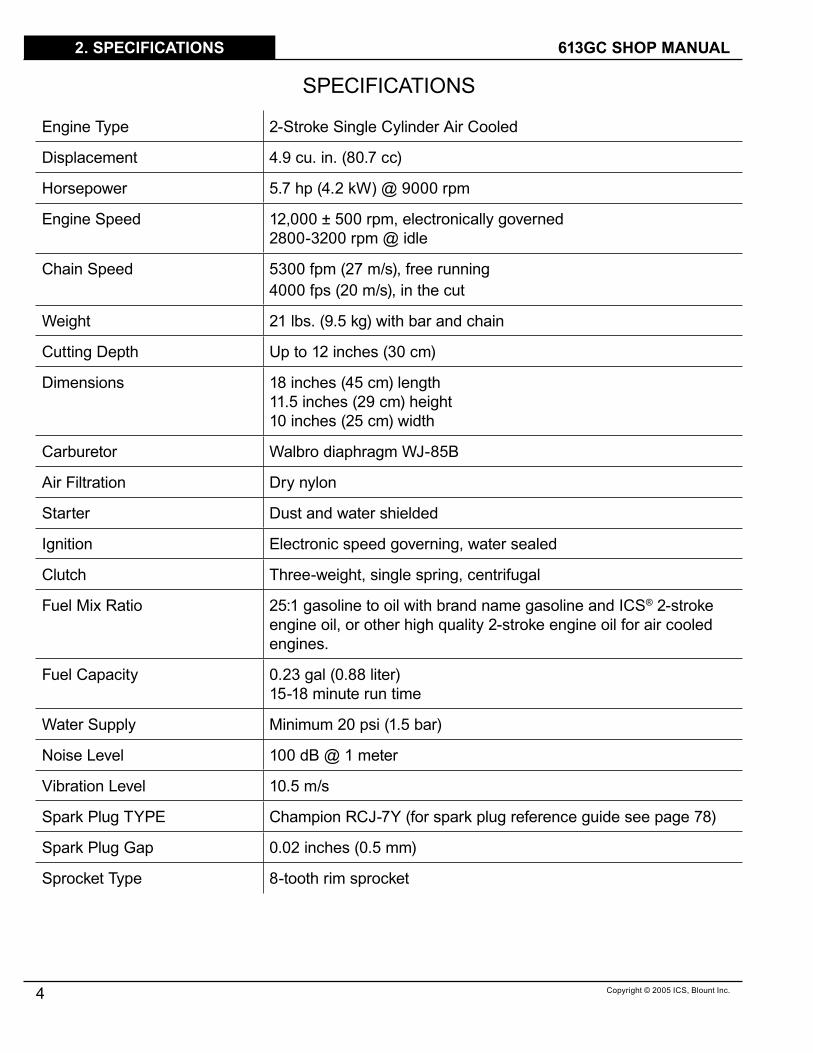
SPECIFICATIONS
Engine Type 2-Stroke Single Cylinder Air Cooled
Displacement 4.9 cu. in. (80.7 cc)
Horsepower 5.7 hp (4.2 kW) @ 9000 rpm
Engine Speed �2,000 ± 500 rpm, electronically governed2800-3200 rpm @ idle
Chain Speed 5300 fpm (27 m/s), free running4000 fps (20 m/s), in the cut
Weight 2� lbs. (9.5 kg) with bar and chain
Cutting Depth Up to �2 inches (30 cm)
Dimensions �8 inches (45 cm) length��.5 inches (29 cm) height�0 inches (25 cm) width
Carburetor Walbro diaphragm WJ-85B
Air Filtration Dry nylon
Starter Dust and water shielded
Ignition Electronic speed governing, water sealed
Clutch Three-weight, single spring, centrifugal
Fuel Mix Ratio 25:� gasoline to oil with brand name gasoline and ICS® 2-stroke engine oil, or other high quality 2-stroke engine oil for air cooled engines.
Fuel Capacity 0.23 gal (0.88 liter)�5-�8 minute run time
Water Supply Minimum 20 psi (�.5 bar)
Noise Level �00 dB @ � meter
Vibration Level �0.5 m/s
Spark Plug TYPE Champion RCJ-7Y (for spark plug reference guide see page 78)
Spark Plug Gap 0.02 inches (0.5 mm)
Sprocket Type 8-tooth rim sprocket

5Copyright © 2005 ICS, Blount Inc.
3. SERIAL # LOCATION
3 6�3GC Cut-Off serial number series.
613GC SHOP MANUAL
613GC SHOP MANUAL
6 Copyright © 2005 ICS, Blount Inc.
4. SPARE PARTS DIAGRAM
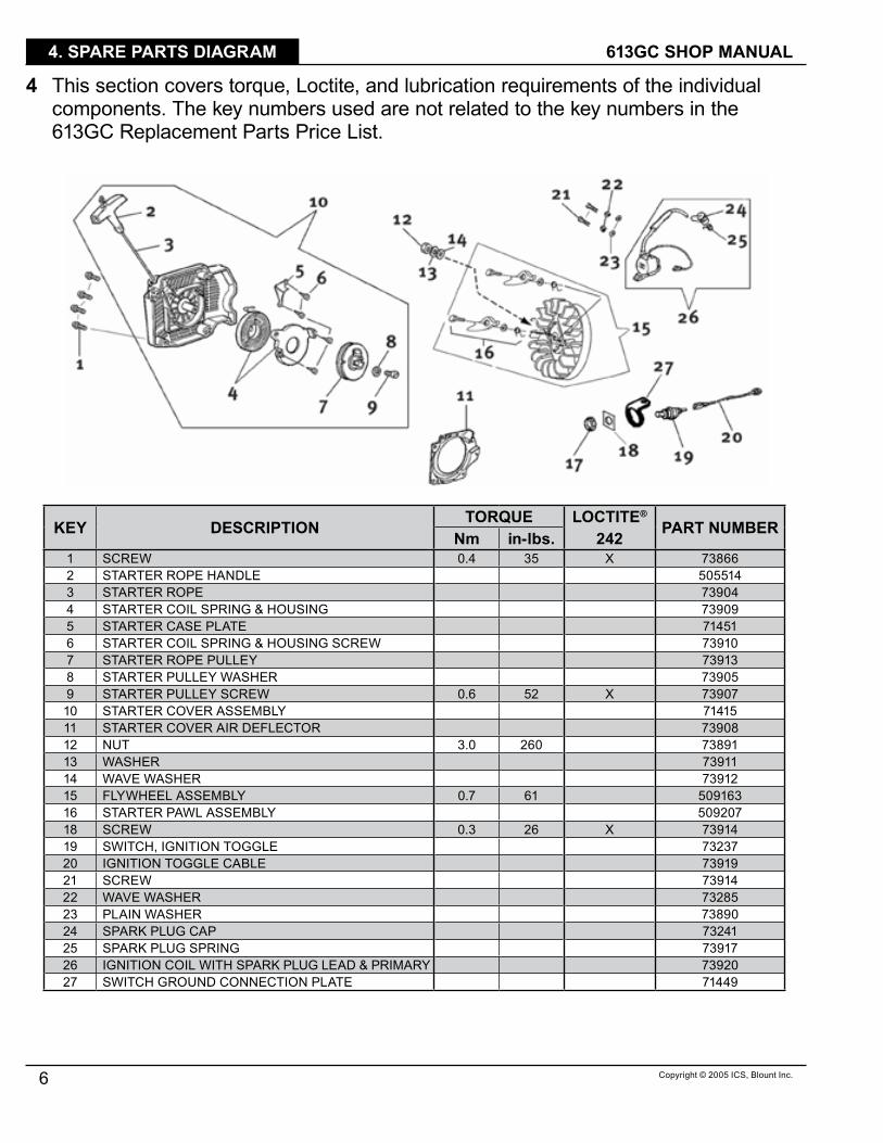
4 This section covers torque, Loctite, and lubrication requirements of the individual components. The key numbers used are not related to the key numbers in the 6�3GC Replacement Parts Price List.
KEY DESCRIPTION TORQUE LOCTITE®
PART NUMBERNm in‑lbs. 242� SCREW 0.4 35 X 738662 STARTER ROPE HANDLE 5055�43 STARTER ROPE 739044 STARTER COIL SPRING & HOUSING 739095 STARTER CASE PLATE 7�45�6 STARTER COIL SPRING & HOUSING SCREW 739�07 STARTER ROPE PULLEY 739�38 STARTER PULLEY WASHER 739059 STARTER PULLEY SCREW 0.6 52 X 73907�0 STARTER COVER ASSEMBLY 7�4�5�� STARTER COVER AIR DEFLECTOR 73908�2 NUT 3.0 260 7389��3 WASHER 739���4 WAVE WASHER 739�2�5 FLYWHEEL ASSEMBLY 0.7 6� 509�63�6 STARTER PAWL ASSEMBLY 509207�8 SCREW 0.3 26 X 739�4�9 SWITCH, IGNITION TOGGLE 7323720 IGNITION TOGGLE CABLE 739�92� SCREW 739�422 WAVE WASHER 7328523 PLAIN WASHER 7389024 SPARK PLUG CAP 7324�25 SPARK PLUG SPRING 739�726 IGNITION COIL WITH SPARK PLUG LEAD & PRIMARY 7392027 SWITCH GROUND CONNECTION PLATE 7�449

613GC SHOP MANUAL
7Copyright © 2005 ICS, Blount Inc.
4. SPARE PARTS DIAGRAM
KEY DESCRIPTION TORQUE LOCTITE®
PART NUMBERNm in‑lbs. 242� REAR MANIFOLD CLAMP 738672 REAR MANIFOLD 738683 WRIST PIN NEEDLE BEARING 738694 COMPLETE PISTON/CYLINDER ASSEMBLY 7�4�35 CYLINDER BASE GASKET ASSEMBLY 7�4�26 SPARK PLUG 2.8 243 73�997 CYLINDER TO MUFFLER GASKET 7388�9 CARBURETOR ATTACHMENT SCREW WASHER 73327�0 MUFFLER ASSEMBLY 7�4���� CYLINDER BLOCK BOLT �.� 95 X 73874�2 MUFFLER MOUNTING SCREW �.0 87 73883�3 CARBURETOR PULSE TUBE 73898�4 MUFFLER SUPPORT BRACKET 73884�5 MUFFLER SUPPORT BRACKET SCREW 0.9 78 73885�6 COMPLETE CARBURETOR WJ-85B 7�762�7 INTAKE MANIFOLD FLANGE SCREW 0.4 35 X 7390��8 WASHER 73250�9 CARBURETOR SUPPORT BRACKET 7389520 DECOMPRESSION VALVE �.3 ��3 7�6422� INTAKE MANIFOLD FLANGE 7394722 INTAKE MANIFOLD 7�73523 CARBURETOR PULSE TUBE PROTECTOR 7388824 WASHER 7389725 CARBURETOR ATTACHMENT SCREW 0.5 43 7390226 SCREW 0.4 35 X 7386627 SCREW GUIDE 0.6 52 7389928 MUFFLER DEFLECTOR 7�48�29 SCREW 0.4 35 7�482

613GC SHOP MANUAL
8 Copyright © 2005 ICS, Blount Inc.
4. SPARE PARTS DIAGRAM
KEY DESCRIPTION TORQUE LOCTITE®
PART NUMBERNm in‑lbs. 242� CRANKSHAFT SEAL FLYWHEEL SIDE 738772 CRANKSHAFT BEARING 732093 CRANKSHAFT FLYWHEEL WOODRUFF KEY 738784 CRANKSHAFT ASSEMBLY 7�4�05 WRIST PIN NEEDLE BEARING 738696 CLUTCH SIDE MAIN BEARING SEAL-INSIDE 732897 CRANKSHAFT BUSHING 7�452
KEY DESCRIPTION TORQUE LOCTITE®
PART NUMBERNm in‑lbs. 242� OUTER CRANKCASE SEAL CLUTCH SIDE 7393�2 OUTER CRANKCASE SEAL BODY 739493 OUTER CRANKCASE SEAL BODY SCREW 0.3 26 739404 WASHER 732855 CLUTCH SPACER WASHER 739456 8T RIM SPROCKET KIT 709497 CLUTCH NEEDLE BEARING 739398 6�3GC CLUTCH DRUM ASSEMBLY 7�5209 CLUTCH SPACER WASHER, INSIDE 7394��0 CLUTCH 3.4 295 7�4�9�� CLUTCH SPRING 73943

613GC SHOP MANUAL
9Copyright © 2005 ICS, Blount Inc.
4. SPARE PARTS DIAGRAM
KEY DESCRIPTION TORQUE LOCTITE®
PART NUMBERNm in‑lbs. 242� GUARD FLAP 7�5342 WALLWALKER® LEVER ARM 7�5323 GUARD FLAP CLAMP 7�53�4 WASHER 7395�5 WALLWALKER® LEVER ARM SCREW 0.5 43 X 7�4786 GUARD FLAP SCREW 0.5 43 X 7�4797 GUARD FLAP WASHER 7�4838 GUARD FLAP SPACER 7�4809 WATER HOSE GASKET 7�469�0 FITTING 7�467�� RING NUT 7�457�2 WATER HOSE O-RING 7�468�3 WATER SHUT-OFF VALVE 7�458�4 FITTING 7�454�5 WATER HOSE 7�455�6 HOSE CLAMP 7�465�7 HOSE HANGER 7�46��8 WATER HOSE COVER 7�464�9 WATER HOSE SCREW 2.0 �74 7�46320 FITTING 7�4532� COPPER WASHER 7�45622 WATER TANK CAP 7392323 FUEL CAP O-RING 7344824 TUBE 7�45925 FITTING 7�47026 FITTING 7�47�27 O-RING 7�47228 HOSE HANGER BUTTON 7�744
613GC SHOP MANUAL
�0 Copyright © 2005 ICS, Blount Inc.
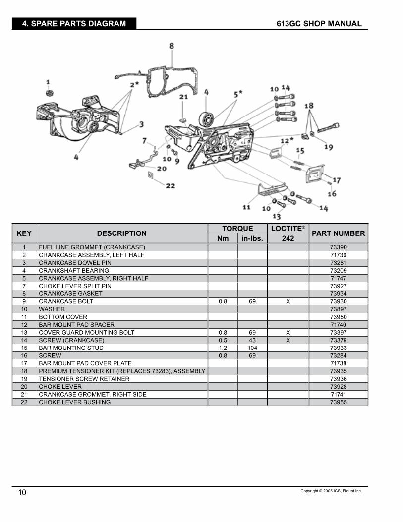
4. SPARE PARTS DIAGRAM
KEY DESCRIPTION TORQUE LOCTITE®
PART NUMBERNm in‑lbs. 242� FUEL LINE GROMMET (CRANKCASE) 733902 CRANKCASE ASSEMBLY, LEFT HALF 7�7363 CRANKCASE DOWEL PIN 7328�4 CRANKSHAFT BEARING 732095 CRANKCASE ASSEMBLY, RIGHT HALF 7�7477 CHOKE LEVER SPLIT PIN 739278 CRANKCASE GASKET 739349 CRANKCASE BOLT 0.8 69 X 73930�0 WASHER 73897�� BOTTOM COVER 73950�2 BAR MOUNT PAD SPACER 7�740�3 COVER GUARD MOUNTING BOLT 0.8 69 X 73397�4 SCREW (CRANKCASE) 0.5 43 X 73379�5 BAR MOUNTING STUD �.2 �04 73933�6 SCREW 0.8 69 73284�7 BAR MOUNT PAD COVER PLATE 7�738�8 PREMIUM TENSIONER KIT (REPLACES 73283), ASSEMBLY 73935�9 TENSIONER SCREW RETAINER 7393620 CHOKE LEVER 739282� CRANKCASE GROMMET, RIGHT SIDE 7�74�22 CHOKE LEVER BUSHING 73955

613GC SHOP MANUAL
��Copyright © 2005 ICS, Blount Inc.
4. SPARE PARTS DIAGRAM
KEY DESCRIPTION TORQUE LOCTITE®
PART NUMBERNm in‑lbs. 242� SIDE COVER INSERT, TOP 7�7432 SIDE COVER NUT �.2 �04 739583 CHAIN COVER CAP 7�4624 MOUNTING NUT 733675 WALLWALKER® SIDE ARM 7�5336 WASHER 7395�7 WALLWALKER® SIDE ARM SCREW 5073558 SCREW 0.3 26 X 7�4879 SIDE COVER PLATE 7�447�0 LOWER GUARD 73957�� SIDE COVER INSERT, BOTTOM REAR 73972�2 SIDE COVER INSERT, TOP REAR 73948�3 SIDE COVER GROMMET 733�0�4 SIDE COVER ASSEMBLY, COMPLETE 7�420

TITLE 613GC SHOP MANUAL
�2 Copyright © 2005 ICS, Blount Inc.
4. SPARE PARTS DIAGRAM

613GC SHOP MANUAL
�3Copyright © 2005 ICS, Blount Inc.
4. SPARE PARTS DIAGRAM
KEY DESCRIPTION TORQUE LOCTITE®
PART NUMBERNm in‑lbs. 242� CYLINDER COVER ASSEMBLY, WITH AIR INTAKE 7�7542 AIR FILTER CANNISTER, POLYESTER 7�7523 AIR FILTER COVER ASSEMBLY, 3 SCREW 7�7534 FILTER COVER SCREW 739925 FILTER SUPPORT 733386 FILTER COVER GASKET 7�7567 SCREW, CYLINDER COVER, LONG, SOCKET HEAD X X X 7�77�8 PREFILTER PLASTIC, SECONDARY FILTER 733369 AIR FILTER FLANGE 7�758�0 FILTER SUPPORT SCREW 0.3 26 X 73337�� FILTER CANNISTER GASKET 73335�2 O-RING 7�472�3 TUBE CLAMP, NO TABS 7�760�4 COMPENSATOR TUBE 7�775�5 BREATHER GROMMET 7�763�6 THROTTLE ASSEMBLY 7�750�7 O-RING, AIR FILTER 7333�

613GC SHOP MANUAL
�4 Copyright © 2005 ICS, Blount Inc.
4. SPARE PARTS DIAGRAM
KEY DESCRIPTION TORQUE LOCTITE®
PART NUMBERNm in‑lbs. 242� FUEL TANK ASSEMBLY (REQUIRES P/N 7�739) 7�42�2 REAR HANDLE HALF 739753 SCREW 0.� 9 739764 THROTTLE LEVER 7�7495 FUEL CAP ASSEMBLY, WITH OUTER SEAL RING 7�7396 FUEL CAP O-RING 734487 FUEL FILTER 734598 TRIGGER LOCKOUT LEVER 739879 TRIGGER LOCKOUT LEVER SPRING 739880 WASHER 73897�� SCREW 0.9 78 X 73982�2 SHOCK ABSORBER 0.4 35 73980�3 TUBE CLAMP, WITH TABS 7�588�4 FUEL LINE 73375�5 SHOCK ABSORBER, REAR HANDLE 7�745�6 BUMPER, SHOCK ABSORBER, FUEL TANK TOP 73270�7 FRONT HANDLE BOLT 0.8 69 X 73983�8 FRONT HANDLE 7�422�9 FUEL BREATHER COMPLETE 7�74820 WATER DEFLECTOR, BOTTOM 7�7662� BREATHER TUBE BODY 7�75�22 BREATHER TUBE ELBOW 7�75923 FUEL BREATHER, REMOTE 7�76�24 BREATHER TUBE EXTENSION 7�77725 TUBE CLAMP, NO TABS 7�760

Copyright © 2005 ICS, Blount Inc.
TITLE613GC SHOP MANUAL
�5
5. AIR INTAKE
5 This section covers the disassembly, inspection, and assembly air induction system.
5.� Loosen the air filter cover screws and remove air filter cover.
5.2 Remove air filter from cover.A Inspect air filter.B Replace if necessary
5.3 Clean filter with cleaning solution and a nylon brush.
A Clean filter with cleaning solution and water.
B Let dry and reinstall.

TITLE 613GC SHOP MANUAL
�6 Copyright © 2005 ICS, Blount Inc.
5. AIR INTAKE
5.4 Inspect air filter cover gasket.A Replace if permanently depressed or
hard due to slurry.5.5 Inspect filter cannister gasket.
A Clean.B Replace if necessary.
5.6 Secure air filter mount screws.

Copyright © 2005 ICS, Blount Inc.
TITLE613GC SHOP MANUAL
�7
6. SPARK PLUG
6 This section covers the removal, inspection, and installation of the spark plug.
6.� Remove the spark plug lead. 6.2 Clean area around the spark plug
to prevent debris from entering the cylinder.
6.3 Remove the spark plug.
6.4 Inspect the spark plug.A If dirty, clean with a wire brush as
shown.

TITLE 613GC SHOP MANUAL
�8 Copyright © 2005 ICS, Blount Inc.
6. SPARK PLUG
B Gap if necessary to 0.02” (0.5 mm).
NOTE: If the spark plug must be replaced refer to the Spark Plug Reference Guide on page 78 to select the correct replacement plug.
6.5 Assemble in the reverse order.A Make sure the plug boot is seated
completely.

Copyright © 2005 ICS, Blount Inc.
TITLE613GC SHOP MANUAL
�9
7. CLUTCH & RIM SPROCKET
7 This section covers clutch removal, rim sprocket removal, inspection, and assembly. Refer to sections 5 and 6 if needed.
7.� Insert piston stop tool into spark plug hole.
7.2 Pull starter handle until piston stops against tool.
7.3 Remove clutch.
Left hand threads – rotate clockwise to loosen.
NOTE: If an impact wrench is available steps 7.� and 7.2 do not have to be performed.
TITLE 613GC SHOP MANUAL
20 Copyright © 2005 ICS, Blount Inc.
7. CLUTCH & RIM SPROCKET
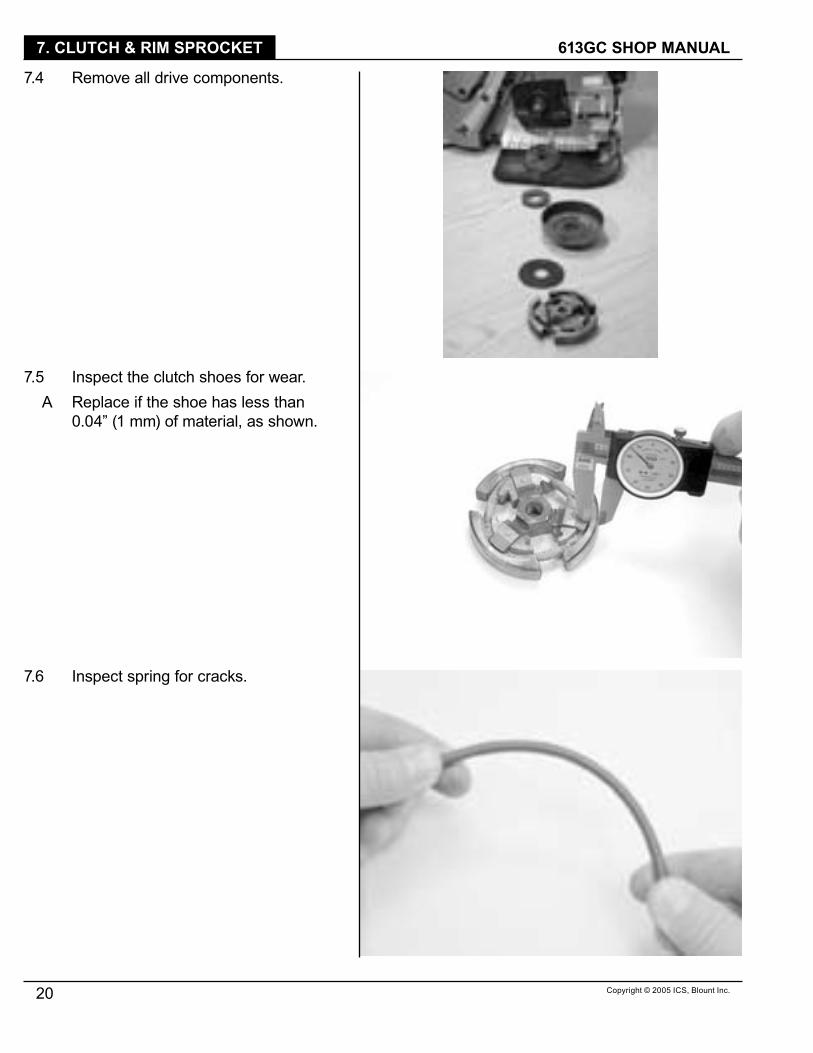
7.4 Remove all drive components.
7.5 Inspect the clutch shoes for wear.A Replace if the shoe has less than
0.04” (� mm) of material, as shown.
7.6 Inspect spring for cracks.

Copyright © 2005 ICS, Blount Inc.
TITLE613GC SHOP MANUAL
2�
7. CLUTCH & RIM SPROCKET
7.7 Assemble clutch shoes as shown.
7.8 Finish installation of clutch shoe as shown.
7.9 Inspect the rim sprocket for wear.A Replace if the rim sprocket teeth are
worn to points, as shown on right.

TITLE 613GC SHOP MANUAL
22 Copyright © 2005 ICS, Blount Inc.
7. CLUTCH & RIM SPROCKET
7.�0 Clean and assemble.A Clean all parts in solvent.B Grease clutch cup bearing with a
water proof grease (ICS® P/N 70885).
C Assemble clutch spacer washer, bearing, clutch cup with rim sprocket, and inside clutch spacer washer.
7.�� Install clutch.A Tighten firmly
Left hand threads

Copyright © 2005 ICS, Blount Inc.
TITLE613GC SHOP MANUAL
23
8. STARTER
8 This section covers the removal of the starter cover, replacement of the starter rope, and replacement of the recoil spring.
8.� Remove starter cover screws. 8.2 Remove starter cover assembly from
saw.
8.3 Remove starter cord shield screws.
8.4 Relieve spring tension. A Pull 4-6” of rope out.B Line rope up with notch on pulley.C Slowly rotate pulley counterclockwise
until spring pressure is released. Use thumb as a brake.
8.5 Remove starter pulley screw and washer.
NOTE: Hold starter cover firmly.
TITLE 613GC SHOP MANUAL
24 Copyright © 2005 ICS, Blount Inc.
8. STARTER
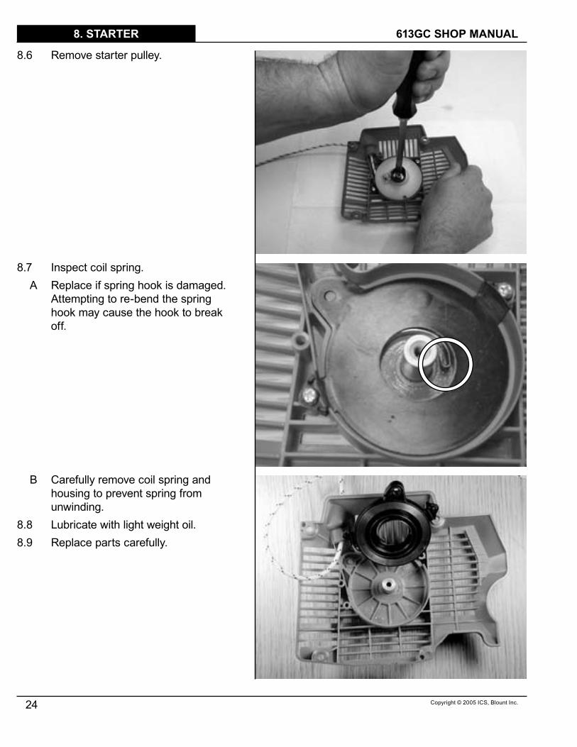
8.6 Remove starter pulley.
8.7 Inspect coil spring.A Replace if spring hook is damaged.
Attempting to re-bend the spring hook may cause the hook to break off.
B Carefully remove coil spring and housing to prevent spring from unwinding.
8.8 Lubricate with light weight oil.8.9 Replace parts carefully.

Copyright © 2005 ICS, Blount Inc.
TITLE613GC SHOP MANUAL
25
8. STARTER
8.�0 Inspect pulley spring catch.A Clean with cleaning solution.B Replace if worn or broken.
8.�� Install starter rope and tie knot.
8.�2 Install pulleyA Wind rope onto pulley clockwise
leaving 4-6” out. B Make sure that the pulley spring
catch is in the spring hook.8.�3 Install center screw.
A Use blue Loctite®.B Torque to 26 in-lbs. (2.9 Nm).
TITLE 613GC SHOP MANUAL
26 Copyright © 2005 ICS, Blount Inc.
8. STARTER
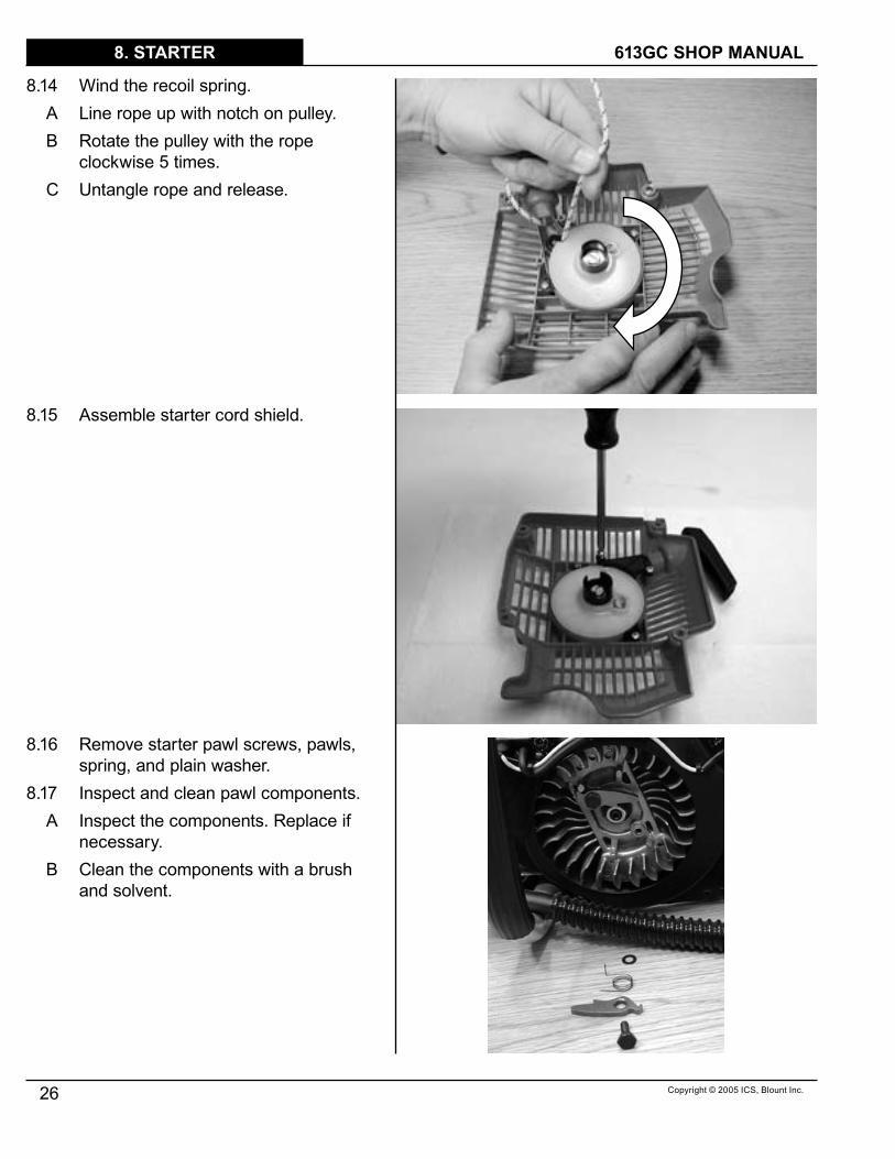
8.�4 Wind the recoil spring.A Line rope up with notch on pulley.B Rotate the pulley with the rope
clockwise 5 times.C Untangle rope and release.
8.�5 Assemble starter cord shield.
8.�6 Remove starter pawl screws, pawls, spring, and plain washer.
8.�7 Inspect and clean pawl components.A Inspect the components. Replace if
necessary.B Clean the components with a brush
and solvent.

Copyright © 2005 ICS, Blount Inc.
TITLE613GC SHOP MANUAL
27
8. STARTER
8.�8 Assemble componentsA Make sure the spring is in the correct
position.B Use blue Loctite® on the pawl screws.C Torque to 60 in-lbs. (6.8 Nm).
8.�9 Wind the pawl spring.A Use needle nose pliers to move the
tail of the spring into position.
8.20 Install starter cover.A Pull out cord 4-6”.B Slowly release while placing cover to
allow pawls to engage.

TITLE 613GC SHOP MANUAL
28 Copyright © 2005 ICS, Blount Inc.
8. STARTER
8.2� Install starter cover screws.A Use blue Loctite®.B Torque to 60 in-lbs. (7 Nm).

Copyright © 2005 ICS, Blount Inc.
TITLE613GC SHOP MANUAL
29
9. WALLWALKER
9 This section covers the removal, inspection, and assembly of the WallWalker® and guard flap.
9.� Inspect WallWalker® tip.A If the tip is worn, as shown, replace.
9.2 Remove crankcase screws and wave washers.
9.3 Remove WallWalker® from saw.
NOTE: On late model saws it is necessary to remove the bar plate prior to removing the crankcase screws.
9.4 Remove guard flap screws and washer.
9.5 Remove and inspect guard flap.A Replace the flap if it is torn or
damaged in any way.

TITLE 613GC SHOP MANUAL
30 Copyright © 2005 ICS, Blount Inc.
9. WALLWALKER
9.6 Reassemble in the reverse order.A Install crankcase screws and wave
washers.B Use blue Loctite®.C Torque to 70 in-lbs. (7.9 Nm).
Copyright © 2005 ICS, Blount Inc.
TITLE613GC SHOP MANUAL
3�
10. CYLINDER COVER
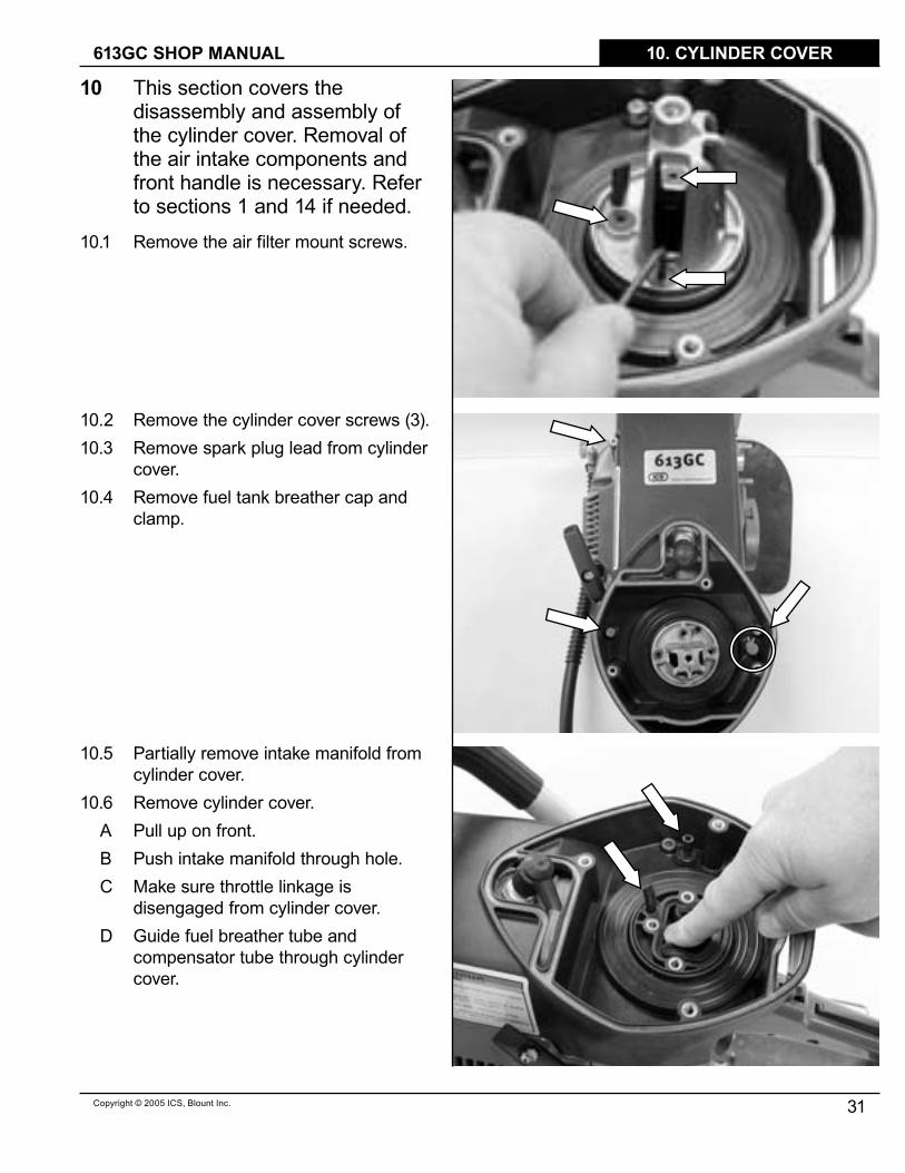
10 This section covers the disassembly and assembly of the cylinder cover. Removal of the air intake components and front handle is necessary. Refer to sections � and �4 if needed.
�0.� Remove the air filter mount screws.
�0.2 Remove the cylinder cover screws (3).�0.3 Remove spark plug lead from cylinder
cover.�0.4 Remove fuel tank breather cap and
clamp.
�0.5 Partially remove intake manifold from cylinder cover.
�0.6 Remove cylinder cover.A Pull up on front.B Push intake manifold through hole.C Make sure throttle linkage is
disengaged from cylinder cover.D Guide fuel breather tube and
compensator tube through cylinder cover.
TITLE 613GC SHOP MANUAL
32 Copyright © 2005 ICS, Blount Inc.
10. CYLINDER COVER
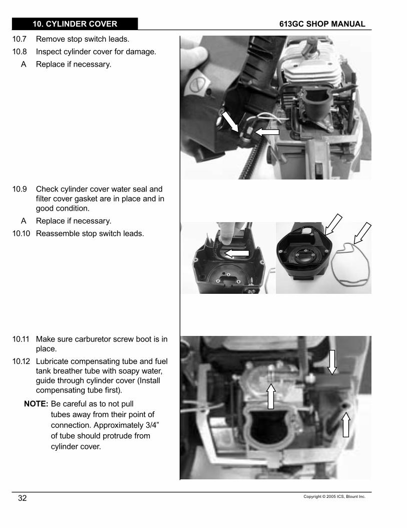
�0.7 Remove stop switch leads.�0.8 Inspect cylinder cover for damage.
A Replace if necessary.
�0.9 Check cylinder cover water seal and filter cover gasket are in place and in good condition.
A Replace if necessary.�0.�0 Reassemble stop switch leads.
�0.�� Make sure carburetor screw boot is in place.
�0.�2 Lubricate compensating tube and fuel tank breather tube with soapy water, guide through cylinder cover (Install compensating tube first).
NOTE: Be careful as to not pull tubes away from their point of connection. Approximately 3/4” of tube should protrude from cylinder cover.

Copyright © 2005 ICS, Blount Inc.
TITLE613GC SHOP MANUAL
33
10. CYLINDER COVER
�0.�3 Install cylinder cover.A Pull spark plug lead into slot in
cylinder cover.B Align throttle linkage with cylinder
cover and crankcase.C Push the cylinder cover down on the
crankcase, guide intake manifold into cylinder cover.
D Install the cylinder cover screws. Use blue Loctite®. Torque to 35 in-lbs. (4.0 Nm).
E Install fuel tank breather and clamp.
�0.�4 Install air filter mount.A Guide carburetor compensating tube
through air filter mount. Make sure manifold sits flat over lip on cylinder cover.
B Install air filter mount screws (3) using blue Loctite®.
C Torque to 43 in-lbs. (4.9 NM).
�0.�5 Install air filters and cover.A Install pre-filterB Install clean air filterC Install air filter flange and tightenD Install air filter cover and tighten
TITLE 613GC SHOP MANUAL
34 Copyright © 2005 ICS, Blount Inc.
11. MUFFLER
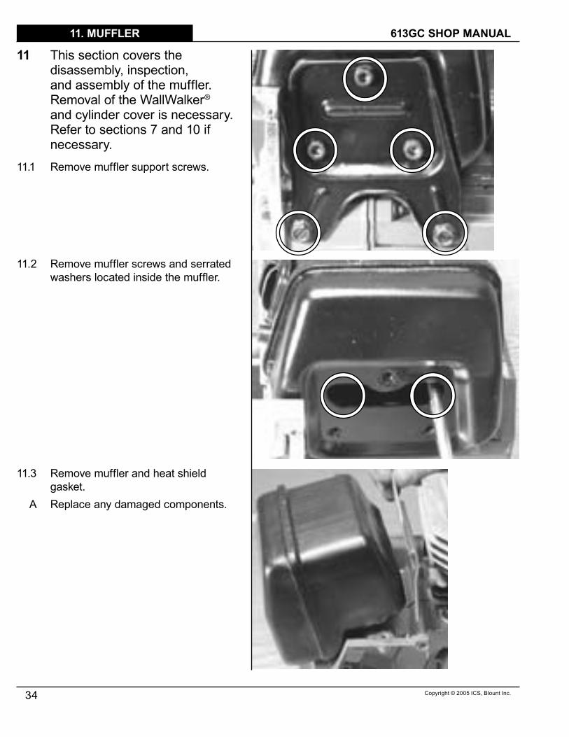
11 This section covers the disassembly, inspection, and assembly of the muffler. Removal of the WallWalker® and cylinder cover is necessary. Refer to sections 7 and �0 if necessary.
��.� Remove muffler support screws.
��.2 Remove muffler screws and serrated washers located inside the muffler.
��.3 Remove muffler and heat shield gasket.
A Replace any damaged components.

Copyright © 2005 ICS, Blount Inc.
TITLE613GC SHOP MANUAL
35
11. MUFFLER
��.4 Install muffler.A Insert muffler screws and serrated
washer (2) into muffler.B Hold muffler screws in place with
heat shield gasket.C Thread muffler screws into cylinder,
torque to 78 in-lbs. (9 Nm).
��.5 Install muffler support.A Install top 3 muffler support screws
and serrated washer finger tight.B Install bottom 2 muffler support
screws with blue Loctite®.C Torque top screws to 78 in-lbs.
(9 Nm).D Torque bottom screws to 52 in-lbs.
(6 Nm).

TITLE 613GC SHOP MANUAL
36 Copyright © 2005 ICS, Blount Inc.
12. CARBURETOR
12 This section covers the removal and installation of the carburetor. Removal of the air intake components and cylinder cover is required. Please refer to sections 5 and �0 or �� if necessary. Carburetor tuning is covered in section 23.
�2.� Remove throttle linkage. A Push trigger end out of rear handle. B Pivot linkage around.C Remove carburetor end of linkage
from throttle rod tab on carburetor.
NOTE: All saws are equipped with carburetor model # WJ-85A.
�2.2 Remove choke lever split pin.�2.3 Remove choke lever.�2.4 Remove adjustment screw boot.

Copyright © 2005 ICS, Blount Inc.
TITLE613GC SHOP MANUAL
37
12. CARBURETOR
�2.5 Remove carburetor support screw (�) with #4 Torx or straight blade screwdriver.
�2.6 Remove carburetor body screws (2).
�2.7 Remove fuel line.�2.8 Remove pulse tube.�2.9 Remove carburetor compensator
tube on top of carburetor.
�2.�0 Assemble in the reverse order.A Torque carburetor body screws to
43 in-lbs. (5 Nm).B Torque supporter screw with blue
Loctite® to 43 in-lbs. (5 Nm).

TITLE 613GC SHOP MANUAL
38 Copyright © 2005 ICS, Blount Inc.
13. CYLINDER & PISTON
13 This section covers the disassembly, inspection and assembly of the cylinder, piston and related components. Removal of several component groups is required. Refer to sections 5, 6, �0, and �2 if necessary.
�3.� Remove carburetor base screws.A Remove carburetor base from rear
manifold.B Remove carburetor base from pulse
tube.
�3.2 Remove pulse tube and protective spring from cylinder base.
NOTE: When replacing the 6�3GC cylinder and piston it is necessary to tune the carburetor prior to returning the saw to service (see section 23).
Copyright © 2005 ICS, Blount Inc.
TITLE613GC SHOP MANUAL
39
13. CYLINDER & PISTON
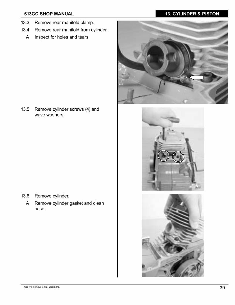
�3.3 Remove rear manifold clamp.�3.4 Remove rear manifold from cylinder.
A Inspect for holes and tears.
�3.5 Remove cylinder screws (4) and wave washers.
�3.6 Remove cylinder.A Remove cylinder gasket and clean
case.

TITLE 613GC SHOP MANUAL
40 Copyright © 2005 ICS, Blount Inc.
13. CYLINDER & PISTON
�3.7 Remove wrist pin retaining clips (2).
�3.8 Press wrist pin out with an 8 mm deep socket.
�3.9 Remove piston and inspect. Replace if damaged.
�3.�0 Remove wrist pin bearing.

Copyright © 2005 ICS, Blount Inc.
TITLE613GC SHOP MANUAL
4�
13. CYLINDER & PISTON
�3.�� Cylinder gasketA Oil gasket with ICS® 2-stroke
engine oil.B Install and align holes and notch.
�3.�2 Install wrist pin bearing in rod.A Oil bearing with ICS® 2-stroke
engine oil.
�3.�3 Install rings.
TITLE 613GC SHOP MANUAL
42 Copyright © 2005 ICS, Blount Inc.
13. CYLINDER & PISTON
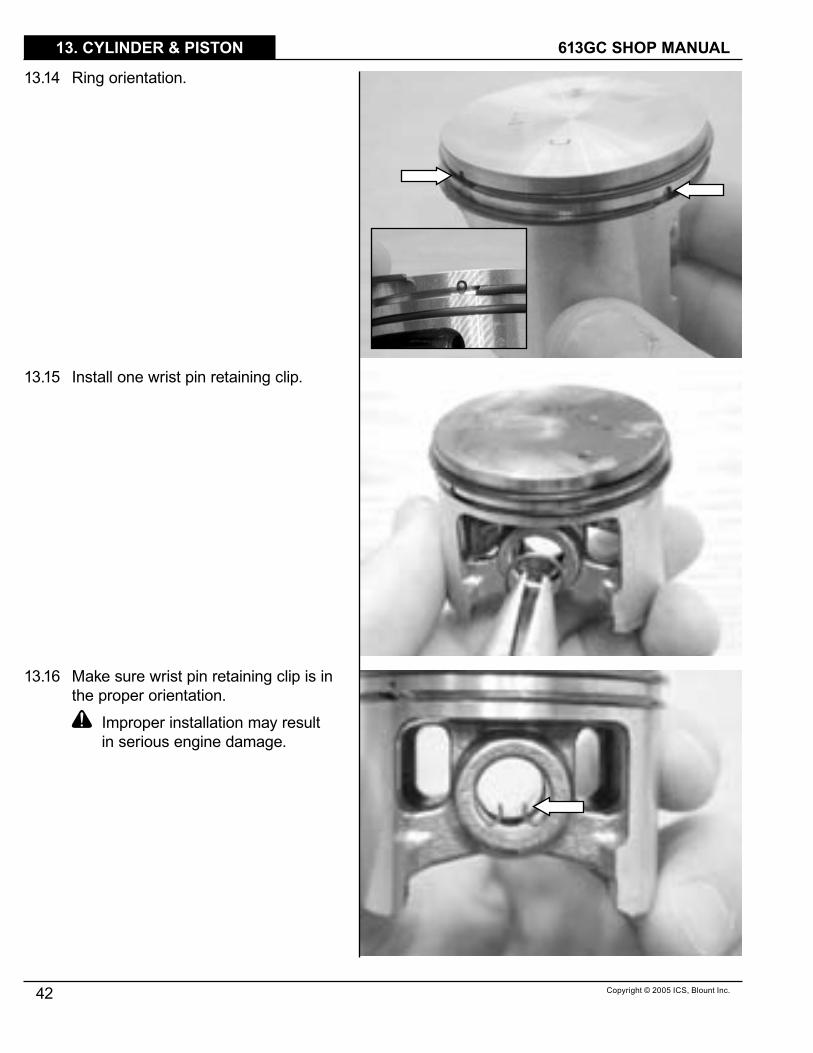
�3.�4 Ring orientation.
�3.�5 Install one wrist pin retaining clip.
�3.�6 Make sure wrist pin retaining clip is in the proper orientation.
Improper installation may result in serious engine damage.
Copyright © 2005 ICS, Blount Inc.
TITLE613GC SHOP MANUAL
43
13. CYLINDER & PISTON
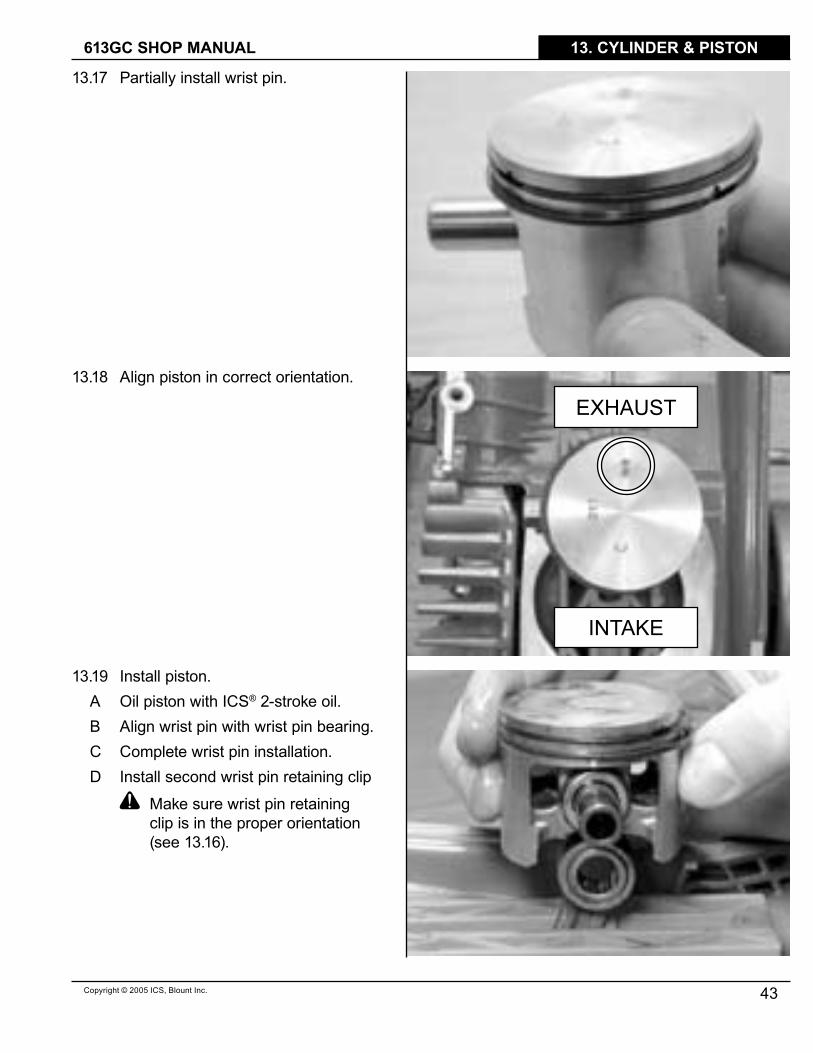
�3.�7 Partially install wrist pin.
�3.�8 Align piston in correct orientation.
�3.�9 Install piston. A Oil piston with ICS® 2-stroke oil.B Align wrist pin with wrist pin bearing.C Complete wrist pin installation.D Install second wrist pin retaining clip
Make sure wrist pin retaining clip is in the proper orientation (see �3.�6).
EXHAUST
INTAKE

TITLE 613GC SHOP MANUAL
44 Copyright © 2005 ICS, Blount Inc.
13. CYLINDER & PISTON
�3.20 Install cylinderA Lubricate cylinder bore with ICS®
2-stroke oil.B Compress rings with ring
compression tool.C Slide cylinder onto piston, pushing
ring compression tool down.
�3.2� Install cylinder.A Remove ring compression tool.B Slide cylinder down piston and into
crankcase.C Align cylinder bolt holes with
crankcase.
�3.22 Install 4 cylinder screws and washers.
A Use blue Loctite®.B Torque bolts to 95.5 in-lbs. (�� Nm)
Copyright © 2005 ICS, Blount Inc.
TITLE613GC SHOP MANUAL
45
13. CYLINDER & PISTON
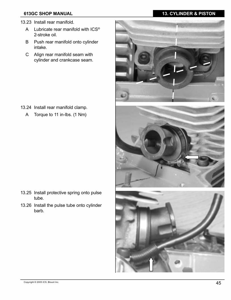
�3.23 Install rear manifold.A Lubricate rear manifold with ICS®
2-stroke oil.B Push rear manifold onto cylinder
intake.C Align rear manifold seam with
cylinder and crankcase seam.
�3.24 Install rear manifold clamp.A Torque to �� in-lbs. (� Nm)
�3.25 Install protective spring onto pulse tube.
�3.26 Install the pulse tube onto cylinder barb.

TITLE 613GC SHOP MANUAL
46 Copyright © 2005 ICS, Blount Inc.
13. CYLINDER & PISTON
�3.27 Install carburetor base.A Slip pulse tube into carburetor base.B Slip rear manifold into carburetor
base.C Make sure rear manifold lip is flat.
�3.28 Install carburetor base screws.A Use blue Loctite® on 3 screws without
ground wire.B Make sure to include stop switch
wire.C Torque to 35 in-lbs. (4 Nm).

Copyright © 2005 ICS, Blount Inc.
TITLE613GC SHOP MANUAL
47
14. WATER HOSE
14 This section covers water hose and water tank cap.
�4.� Loosen hose clamp screw.�4.2 Remove water connection from hose.�4.3 Remove hose from hose hanger.
�4.4 Remove water hose connector.
�4.5 Unscrew water tank cap from saw.

TITLE 613GC SHOP MANUAL
48 Copyright © 2005 ICS, Blount Inc.
14. WATER HOSE
�4.6 Release water tank cap from water tank tube.
A Depress orange fitting as shown.�4.7 Assemble in the reverse order.
Copyright © 2005 ICS, Blount Inc.
TITLE613GC SHOP MANUAL
49
15. IGNITION COIL
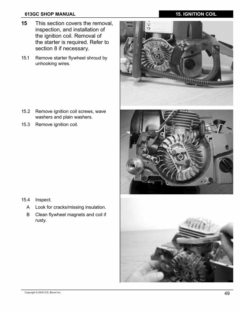
15 This section covers the removal, inspection, and installation of the ignition coil. Removal of the starter is required. Refer to section 8 if necessary.
�5.� Remove starter flywheel shroud by unhooking wires.
�5.2 Remove ignition coil screws, wave washers and plain washers.
�5.3 Remove ignition coil.
�5.4 Inspect.A Look for cracks/missing insulation. B Clean flywheel magnets and coil if
rusty.

TITLE 613GC SHOP MANUAL
50 Copyright © 2005 ICS, Blount Inc.
15. IGNITION COIL
�5.5 Install Ignition coil.A Place ignition coil shim (0.0�2”)
on magnet counterweight side of flywheel.
B Set ignition coil in place.C Install ignition coil screws, wave
washers, and plain washers with blue Loctite®.
Holding shim, rotate flywheel magnet around to coil.
E Torque ignition coil screws to 26 in-lbs. (3 Nm).
F Remove shim, rotate flywheel to check clearance.
�5.6 Install flywheel shroud�5.7 Route yellow ignition stop switch wire
through crankcase into carburetor chamber.
�5.8 Complete ignition wire routing.
Copyright © 2005 ICS, Blount Inc.
TITLE613GC SHOP MANUAL
5�
16. FLYWHEEL
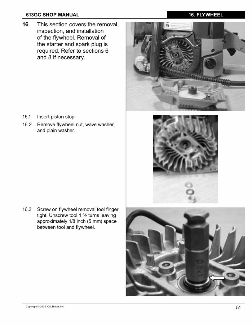
16 This section covers the removal, inspection, and installation of the flywheel. Removal of the starter and spark plug is required. Refer to sections 6 and 8 if necessary.
�6.� Insert piston stop.�6.2 Remove flywheel nut, wave washer,
and plain washer.
�6.3 Screw on flywheel removal tool finger tight. Unscrew tool � ½ turns leaving approximately �/8 inch (5 mm) space between tool and flywheel.
TITLE 613GC SHOP MANUAL
52 Copyright © 2005 ICS, Blount Inc.
16. FLYWHEEL
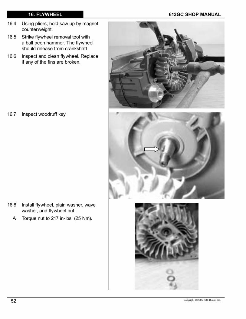
�6.4 Using pliers, hold saw up by magnet counterweight.
�6.5 Strike flywheel removal tool with a ball peen hammer. The flywheel should release from crankshaft.
�6.6 Inspect and clean flywheel. Replace if any of the fins are broken.
�6.7 Inspect woodruff key.
�6.8 Install flywheel, plain washer, wave washer, and flywheel nut.
A Torque nut to 2�7 in-lbs. (25 Nm).
Copyright © 2005 ICS, Blount Inc.
TITLE613GC SHOP MANUAL
53
17. BOTTOM GUARD
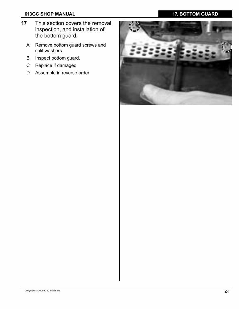
17 This section covers the removal inspection, and installation of the bottom guard.
A Remove bottom guard screws and split washers.
B Inspect bottom guard.C Replace if damaged.D Assemble in reverse order

TITLE 613GC SHOP MANUAL
54 Copyright © 2005 ICS, Blount Inc.
18. FRONT HANDLE
18 This section covers the removal, inspection, and installation of the front handle.
�8.� Remove front handle screws on right side.
�8.2 Remove front handle screws on bottom.
�8.3 Install front handle.A Roll front handle into place.B Install front handle screws (4).C Use blue Loctite®.D Torque to 69 in-lbs. (8 Nm).

Copyright © 2005 ICS, Blount Inc.
TITLE613GC SHOP MANUAL
55
19. FUEL TANK
19 This section covers the disassembly, inspection, and assembly of the vibration isolaters, fuel tank, and rear handle.
�9.� Remove vibration isolator screws and wave washers on clutch side of saw.
�9.2 Remove vibration isolator screws and wave washers on flywheel side of saw.

TITLE 613GC SHOP MANUAL
56 Copyright © 2005 ICS, Blount Inc.
19. FUEL TANK
�9.3 Separate crankcase and fuel tank.
NOTE: Saws have a rubber water deflector connected to the 2 bottom vibration isolators on the clutch side (circled).
�9.4 Remove vibration isolators from fuel tank (6) if necessary.
�9.5 Assemble in reverse order.
NOTE: During assembly be careful to avoid kinking the fuel line.

Copyright © 2005 ICS, Blount Inc.
TITLE613GC SHOP MANUAL
57
20. CRANKCASE
20 This section covers the disassembly, inspection, and assembly of the crankcase seals and crankshaft bearings.
20.� Remove outer crankshaft seal housing screws and wave washers.
20.2 Remove crankcase bolts.

TITLE 613GC SHOP MANUAL
58 Copyright © 2005 ICS, Blount Inc.
20. CRANKCASE
20.3 Heat the flywheel side crankcase with heat gun for 5 minutes, approximately �50° F (65.5° C).
20.4 Remove the flywheel side crankcase – tap crankshaft with plastic mallet.
A Suspend above work surface.B Tap with mallet.
NOTE: A nut should always be placed on a threaded shaft when pounding or pressing on it.
20.5 Remove the flywheel side crankcase seal with �/2” (�3 mm) socket.
Copyright © 2005 ICS, Blount Inc.
TITLE613GC SHOP MANUAL
59
20. CRANKCASE
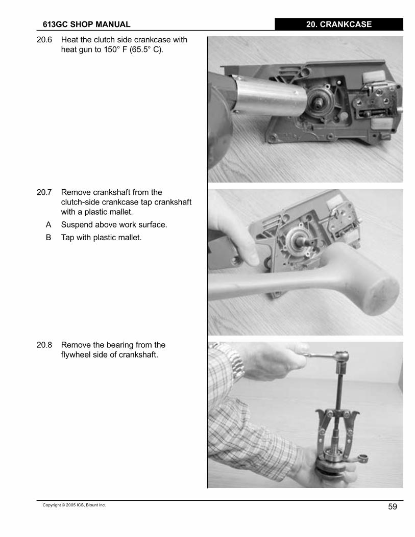
20.6 Heat the clutch side crankcase with heat gun to �50° F (65.5° C).
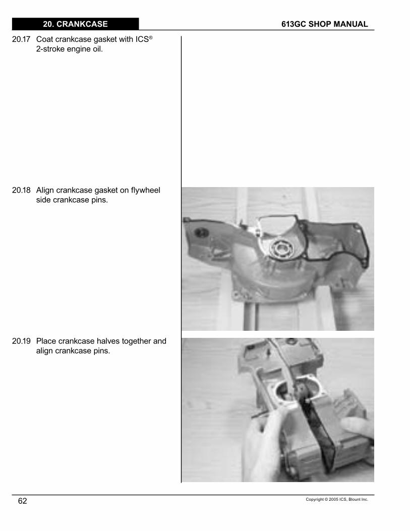
20.7 Remove crankshaft from the clutch-side crankcase tap crankshaft with a plastic mallet.
A Suspend above work surface.B Tap with plastic mallet.
20.8 Remove the bearing from the flywheel side of crankshaft.

TITLE 613GC SHOP MANUAL
60 Copyright © 2005 ICS, Blount Inc.
20. CRANKCASE
20.9 Remove the bearing, seal, and bushing from the clutch side of crankshaft.
20.�0 Clean mating crankcase faces.20.�� Heat crankcase halves to �50° F.
20.�2 Install bearing into crankcase halves.20.�3 Tap with bearing driver and mallet.

Copyright © 2005 ICS, Blount Inc.
TITLE613GC SHOP MANUAL
6�
20. CRANKCASE
20.�4 Repeat with other half.
20.�5 Install crankshaft into clutch side of case.
20.�6 Place clutch side crank case seal on crankshaft.
A Tap lightly with bearing driver and mallet.
TITLE 613GC SHOP MANUAL
62 Copyright © 2005 ICS, Blount Inc.
20. CRANKCASE
20.�7 Coat crankcase gasket with ICS® 2-stroke engine oil.
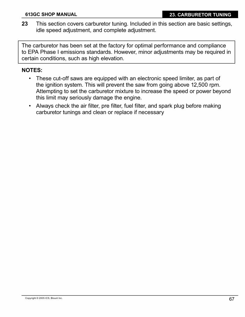
20.�8 Align crankcase gasket on flywheel side crankcase pins.
20.�9 Place crankcase halves together and align crankcase pins.

Copyright © 2005 ICS, Blount Inc.
TITLE613GC SHOP MANUAL
63
20. CRANKCASE
20.20 Assemble crankcase halves – tap with bearing driver and mallet.
20.2� Install main crankcase bolts. A Use blue Loctite®.B Torque to 69 in-lbs. (8 Nm).
NOTE: The 3 remaining crankcase bolts will be installed during the completion of the saw assembly.
20.22 Install flywheel side crankcase seal – tap with bearing driver and mallet.

TITLE 613GC SHOP MANUAL
64 Copyright © 2005 ICS, Blount Inc.
20. CRANKCASE
20.23 Trim crankcase gasket flush.

Copyright © 2005 ICS, Blount Inc.
TITLE613GC SHOP MANUAL
65
21. BAR STUDS & BAR PAD
21 This section covers the removal and installation of the bar studs and bar pad.
NOTE: On saws with Serial #’s beginning 048242�700 and 07�XXXXXXX, it is necessary to remove the bar mount pad cover plate first.
2�.� Remove bar studs.A Remove side cover.B Install side cover nuts, flange to
flange and tighten together.C Attempt to remove the inside nut
which should pull out the bar stud.D Repeat on second bar stud.
2�.2 Remove bar pad.A Remove sealing o-ring.
2�.3 Assemble in reverse order.

TITLE 613GC SHOP MANUAL
66 Copyright © 2005 ICS, Blount Inc.
22. CHAIN TENSIONER
22 This section covers the removal and installation of the chain tensioner.
22.� Remove bar plate to expose the chain tensioner.
NOTE: Saws with serial #’s lower than 048242�700 are not equipped with a bar mount pad cover plate.
22.2 Unscrew tensioner to remove. A Remove tensioner pin.B Remove tensioner screw keeper.
22.3 Assemble in reverse order.
TITLE613GC SHOP MANUAL
67Copyright © 2005 ICS, Blount Inc.
23. CARBURETOR TUNING
23 This section covers carburetor tuning. Included in this section are basic settings, idle speed adjustment, and complete adjustment.
The carburetor has been set at the factory for optimal performance and compliance to EPA Phase I emissions standards. However, minor adjustments may be required in certain conditions, such as high elevation.
NOTES:• These cut-off saws are equipped with an electronic speed limiter, as part of
the ignition system. This will prevent the saw from going above �2,500 rpm. Attempting to set the carburetor mixture to increase the speed or power beyond this limit may seriously damage the engine.
• Always check the air filter, pre filter, fuel filter, and spark plug before making carburetor tunings and clean or replace if necessary
TITLE 613GC SHOP MANUAL
68 Copyright © 2005 ICS, Blount Inc.
23. CARBURETOR TUNING
23.� Basic Setting -
H = � 3/4 turns from closed
L = � �/4 turns from closed
Complete carburetor readjustment.
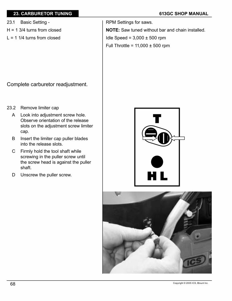
23.2 Remove limiter capA Look into adjustment screw hole.
Observe orientation of the release slots on the adjustment screw limiter cap.
B Insert the limiter cap puller blades into the release slots.
C Firmly hold the tool shaft while screwing in the puller screw until the screw head is against the puller shaft.
D Unscrew the puller screw.
RPM Settings for saws.
NOTE: Saw tuned without bar and chain installed.
Idle Speed = 3,000 ± 500 rpm
Full Throttle = ��,000 ± 500 rpm

Copyright © 2005 ICS, Blount Inc.
TITLE613GC SHOP MANUAL
69
23. CARBURETOR TUNING
23.3 Using a 5/64” straight blade screwdriver, gently turn the adjustment screws clockwise until completely closed.
23.4 Set the adjustment screws at the Basic Setting:
H = � 3/4 turns from closedL = � �/4 turns from closed
The side cover must be held tightly in place with the side cover nuts, using a bar and no chain. Failure to do so may result in personal injury.
23.5 Start the saw and warm up the engine.
23.6 With a tachometer check the saw rpm, with no bar and chain:
A Idle = 3,000 ± 300 rpm B If the idle rpm does not fall into this
rang, adjust the T screw, clockwise to raise RPM, counterclockwise to lower RPM.
23.7 With a tachometer check the saw full throttle rpm, with no bar and chain:
A Target = ��,000 ± 500 rpm 23.8 If the full throttle rpm falls below this
range, turn the H screw in (clockwise) �/�6th of a turn at a time.
A Pulse the throttle to help stabilize the system.
Do not hold the saw at max rpm for more than 5 seconds or cylinder damage could occur.

TITLE 613GC SHOP MANUAL
70 Copyright © 2005 ICS, Blount Inc.
23. CARBURETOR TUNING
23.9 When the carburetor is adjusted correctly set the limiter caps as shown with a �/4” straight blade screwdriver.
A L = verticalB H = horizontal

Copyright © 2005 ICS, Blount Inc.
TITLE613GC SHOP MANUAL
7�
24. IDLE SPEED ADJUSTMENT
24 This section covers idle speed adjustment.
24.� If engine stops while idling:A Make sure the chain is properly
tensioned.B Turn T screw clockwise until chain
begins to moveC Back T screw out ½ turn.
24.2 If chain turns at idle:A Back T screw out until chain stops
moving.

613GC SHOP MANUAL
72 Copyright © 2005 ICS, Blount Inc.
25. DIAGRAMS
25 This section provides several flowcharts to aid diagnosing common problems.
CHECK POSSIBLE CAUSE REPAIR
The engine runs rough at all speeds
The engine is overheating.
• Operator is overworking the saw.
• Carburetor mixture is too lean.
• Incorrect fuel/oil ratio.• Flywheel fins are clogged.• Air deflector is missing.• Cylinder fins are clogged
Poor acceleration.
• Dirty or clogged air filter.• Clogged fuel filter.• Incorrect carburetor tune.• Plugged tank breather.• Blocked pulse tube.
Uneven idle or engine may “run away”
• Air leak at intake boot, cylinder gasket, or crankcase gasket.
• Faulty carburetor diaphragm.
Diamond chain moves at idle.
• Idle speed too high.• Broken clutch spring.
Excessive vibration. YES• Damaged shock absorber.• Damaged or broken
flywheel fins.• Bent crankshaft.
• Replace shock absorbers• Replace flywheel.• Replace crankshaft.
• Adjust idle speed.• Replace clutch spring.YES
• Inspect air intake boot.• Pressure test crankcase.• Replace carburetor.
YES
• Clean or replace the air filter.• Replace fuel filter.• See Carburetor Tuning section.• Repair or replace fuel tank
breather.• Replace pulse tube.
YES
• See Operator’s Manual.• See Carburetor Tuning section.• See Saw Specifications section.• Clean flywheel fins with wire
brush.• See Starter Cover section.• Clean cylinder fins.
YES
• Dirty or clogged air filter.• Water has been ingested.• Loose or dirty spark plug.
• Clean or replace the air filter.• Inspect air intake sysetm for water.• Inspect fuel system for water.• Tighten, clean, or replace spark
plug.
YES
A dirty air filter is the #� reason for engine problems.
613GC SHOP MANUAL
73Copyright © 2005 ICS, Blount Inc.
25. DIAGRAMS
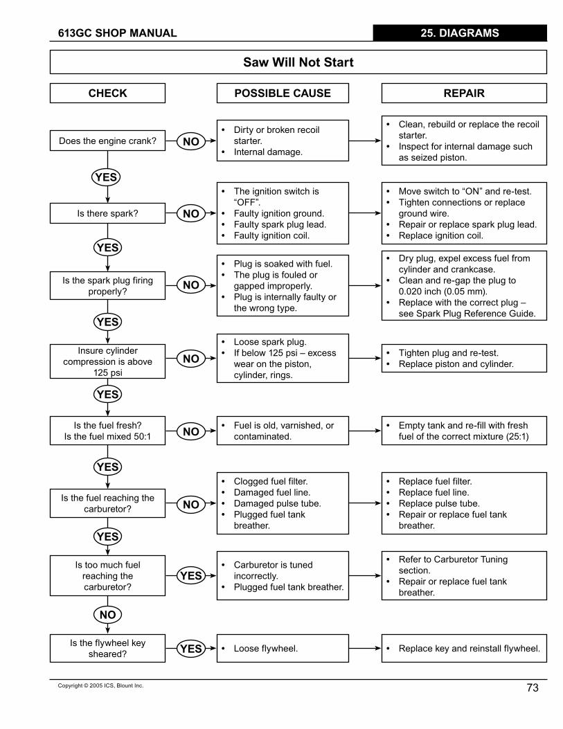
Saw Will Not Start
CHECK POSSIBLE CAUSE REPAIR
Does the engine crank?
Is there spark?
Is the spark plug firingproperly?
Insure cylinder compression is above
�25 psi
Is the fuel fresh?Is the fuel mixed 50:�
Is the fuel reaching the carburetor?
Is too much fuel reaching the carburetor?
Is the flywheel key sheared? • Loose flywheel. • Replace key and reinstall flywheel.
• Carburetor is tuned incorrectly.
• Plugged fuel tank breather.
• Refer to Carburetor Tuning section.
• Repair or replace fuel tank breather.
• Clogged fuel filter.• Damaged fuel line.• Damaged pulse tube.• Plugged fuel tank
breather.
• Replace fuel filter.• Replace fuel line.• Replace pulse tube.• Repair or replace fuel tank
breather.
• Fuel is old, varnished, or contaminated.
• Empty tank and re-fill with fresh fuel of the correct mixture (25:�)
• Loose spark plug.• If below �25 psi – excess
wear on the piston, cylinder, rings.
• Tighten plug and re-test.• Replace piston and cylinder.
• Plug is soaked with fuel.• The plug is fouled or
gapped improperly.• Plug is internally faulty or
the wrong type.
• Dry plug, expel excess fuel from cylinder and crankcase.
• Clean and re-gap the plug to 0.020 inch (0.05 mm).
• Replace with the correct plug – see Spark Plug Reference Guide.
• The ignition switch is “OFF”.
• Faulty ignition ground.• Faulty spark plug lead.• Faulty ignition coil.
• Move switch to “ON” and re-test.• Tighten connections or replace
ground wire.• Repair or replace spark plug lead.• Replace ignition coil.
• Dirty or broken recoil starter.
• Internal damage.
• Clean, rebuild or replace the recoil starter.
• Inspect for internal damage such as seized piston.
YES
YES
YES
YES
YES
YES
NO
YES
YES
NO
NO
NO
NO
NO
NO
TITLE 613GC SHOP MANUAL
74 Copyright © 2005 ICS, Blount Inc.
26. FUEL SYSTEM LEAKS
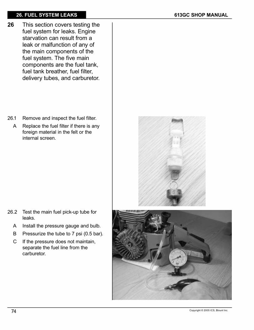
26 This section covers testing the fuel system for leaks. Engine starvation can result from a leak or malfunction of any of the main components of the fuel system. The five main components are the fuel tank, fuel tank breather, fuel filter, delivery tubes, and carburetor.
26.� Remove and inspect the fuel filter.A Replace the fuel filter if there is any
foreign material in the felt or the internal screen.
26.2 Test the main fuel pick-up tube for leaks.
A Install the pressure gauge and bulb.B Pressurize the tube to 7 psi (0.5 bar).C If the pressure does not maintain,
separate the fuel line from the carburetor.

Copyright © 2005 ICS, Blount Inc.
TITLE613GC SHOP MANUAL
75
26. FUEL SYSTEM LEAKS
D Plug one end of the main fuel pick-up tube.
E Re-pressurize the tube to 7 psi (0.5 bar).
F Replace the tube if pressure is not maintained.
G If the main fuel pick-up tube does maintain pressure, then the leak ha been isolated to the carburetor. Refer to the Walbro Diaphragm Carburetor Service Manual.
26.3 The fuel tank breather stabilizes the pressure in the fuel tank preventing both excessive pressure, which could flood the engine, and negative pressure, which could starve the engine of fuel.
26.4 Fuel tank breather is located inside the air filter compartment.

TITLE 613GC SHOP MANUAL
76 Copyright © 2005 ICS, Blount Inc.
26. FUEL SYSTEM LEAKS
26.5 Testing the fuel tank breather.A Attach the pressure gauge and bulb
to the main fuel pick-up tube at the carburetor. Pressurize the tube to 4.5 psi (0.3 bar).
B The pressure should reduce to nearly 0 psi (0 bar) over about 3 seconds.
26.6 If the pressure does not reduce to 0 psi, disassemble or replace the breather.
A Clean the parts with solvent or fuel.B Assemble in reverse order.C Make sure that the spring taper is
oriented in the correct direction.

Copyright © 2005 ICS, Blount Inc.
TITLE613GC SHOP MANUAL
77
27. CRANKCASE LEAKS
27 This section covers testing the crankcase for leaks. A leak in the crankcase can cause the engine not to run.
27.� Install the intake seal flange.A Plug cylinder pulse tube.
27.2 Install the exhaust seal flange.27.3 Block one of the flange tubes with a
rubber plug.
27.4 Install the pressure gauge and bulb.27.5 Pressurize the crankcase to 7 psi (0.5
bar).27.6 If the pressure does not remain the
same, use soapy water to find the leak.
NOTE: It is recommended that this test be performed after an engine rebuild

613GC SHOP MANUAL
78 Copyright © 2005 ICS, Blount Inc.
APPENDIX
1 The Spark Plug Reference Guide is to be used as a guide only. When trying a plug from a different manufacturer, perform a plug check to be sure that the plug will work.
SPARK PLUG REFERENCE GUIDE
ICS RESISTOR CHAMPIONRESISTOR
NGK RESISTOR BOSCH RESISTOR
73�99 RCJ7Y BPMR7A WSR7F


ICS, Blount Inc. 4909 SE International Way Portland, Oregon 97222 TEL 800-32�-�240 FAX 503-653-4393
www.icsbestway.comp/n 7�537