Embed Size (px)
Citation preview


61
Chapter 3 Pipelined Vector ProcessorsIn the early 1970s, computer designers turned to pipelined vector processors to achieve higher
performance. The pipelined vector processors were a natural evolution from the high performanceserial machines of the day. To increase performance, the designers added special machineinstructions for operating on vectors of numerical values which exploited the available parallelismin pipelined functional units.
In 1973, Control Data Corporation shipped the first vector processor called the STAR 100.Though historically first, the STAR 100 was not completely successful due partly to the use ofmagnetic-core memory, an old technology which had been surpassed by semiconductor memory.Furthermore, the best serial computers, i. e., the CDC 7600 and the IBM 360/195, had muchfaster arithmetic units for scalar operations and, therefore, the STAR 100 was slower except onvery long vectors.
In 1976, the highly successful Cray-1 was introduced. Unlike the STAR 100, the Cray-1could perform fast scalar arithmetic and even faster arithmetic on vectors. Since the Cray-1 is aclassic example of a pipelined vector processor, this chapter will use the Cray-1 as its primaryexample. We will contrast the register-to-register style of the Cray-1’s vector operations with thememory-to-memory style of the CDC 205. The CDC 205 is a re-engineered version of ControlData’s STAR 100. We will discuss both the need of vectorizing compilers in order to exploit theparallelism introduced by the pipelined vector processors, and the changes in programming styleintroduced by these vector processors.
3.1 The Cray-1 SupercomputerIn 1972, Seymour Cray left Control Data Corporation to start his own company, Cray
Research, Inc., with the aim of producing the fastest computer in the world. In the extraordinarilyshort time of four years, the Cray-1 computer was designed and built (1976). The Cray-1 followsthe evolutionary trend of Seymour Cray’s CDC 6600 and CDC 7600. Where the ten seriallyorganized functional units of the CDC 6600 had been replaced by eight pipelined functional units inthe CDC 7600, Seymour Cray increased the number of pipelined functional units in the Cray-1 totwelve. We will first discuss the physical characteristics of the machine and then its architecture.

62 CHAPTER 3 PIPELINED VECTOR PROCESSORS
Fig. 3.1 The Cray-1 Supercomputer (Photograph courtesy of Cray Research, Inc.)
3.1.1 Physical Characteristics of the Cray-1
The Cray-1 has been called “the world’s most expensive love-seat.” The machine comprises acentral 4.5 foot diameter cylindrical column 6.5 feet high, surrounded by the circular “love-seat”bringing the diameter at floor level to about 9 feet. The most striking feature of the Cray-1 is itsmall size. This is well illustrated in Figure 3.1. In computer design, smaller means faster. Thegreater the separation of components, the longer the time taken for a signal to pass between them.A cylindrical shape was chosen for the Cray-1 in order to keep wiring distances short. Themaximum signal path is 3.5 feet. The cabinet for the CPU and memory is composed of 12 wedge-like columns in a 270 degree arc. “This leaves room for a reasonably trim individual to gain accessto the interior of the machine.”24
The love-seat around the base of the Cray-1 encloses the power supplies and some plumbingassociated with the Freon cooling. Two 25-ton compressors comprise the Freon cooling systemand are located externally to the computer room. The total power consumption of the machine is128 kW, most of which generates heat that must be removed by the Freon cooling system. TheCray-1 cost about five million dollars and was affordable only by large national scientificlaboratories where absolute performance at any cost was important.
3.1.2 Architecture of the Cray-1
An architectural diagram of the Cray-1 is given in Figure 3.2.
24 Russell, Richard M., “The CRAY-1 Computer System,” Communications of the ACM, Vol. 21, No. 1, Jan.,1978, pp. 64.

3.1 The Cray-1 Supercomputer 63
63
through V0
V764-bit
T
AddLogical
Shift
AddMultiply
Recip. Ap.
AddLogical
ShiftPop./LZ
AddMultiply
Vector Functional
Units
Floating- Point
Functional Units
Scalar Functional
Units
Address Functional
Units
0
Scalar Registers
Address Registers
Vector Registers
through
through
through
through
0
0
0
T
7
63
63
B
B
SS
AA
0 7
Scalar Buffers
Address Buffers
Instruction Buffers
0
63Instructional
UnitExecution
16-bit
24-bit24-bit
64-bit64-bit
Mem
ory
1 M
64-
bit W
ords
IB
IB
IB
IB
0
1
2
3
Fig.3.2 Architecture of the Cray-1
Functional Units
The Cray-1’s twelve independent functional units -- organized in four groups: Vector,Floating-point, Scalar and Address -- are shown on the right side of Figure 3.2. Each functionalunit is pipelined and can deliver a result every clock period. Note that all the functional units useparallelism in the form of pipelining and all can operate at the same time (replication parallelism).Note further the absence of a divide unit in the Cray-1. Since floating point division cannot bepipelined, the Cray-1 performs a floating-point division by performing a reciprocal approximationfollowed by a multiply as illustrated by the following mathematical identity:
xy =
1y * x
This approach has the advantage that reciprocal approximation can be pipelined.

64 CHAPTER 3 PIPELINED VECTOR PROCESSORS
The Pop./LZ (population and leading zero count) functional unit counts the number of ones orthe number of leading zeros in an argument.
Registers
The Cray-1 has over 4 Kbytes of high speed (6 nanoseconds) register storage organized asshown in the middle vertical section of Figure 3.2. Since the Cray-1 is a register-to-registerarchitecture, the twelve functional units use operands from and store results to the A, S and Vregisters. The B and T registers are used as auxiliary storage for the A and S registers,respectively.
The eight 24-bit A registers are primarily used as address registers for memory references andas index registers, but also are used to provide values for shift counts, loop control, and channelI/O operations. The Address functional units use the A registers to operate on 24-bit integers tomodify addresses by adding, subtracting and multiplying A register quantities. The results arereturned to the A registers to be used by the Instructional Unit in the instruction and data fetchstages of instructions.
The eight 64-bit S registers are used for scalar operations. Logical, shift, fixed-point (i. e., 64-bit integer) and floating-point operations may be performed on the values in the S registers. Also,scalar quantities involved in vector operations are held in the S registers.
The eight 64-element V registers provide vector operands to and receive vector results from theVector and Floating-point functional units at the rate of one result per clock period. Each elementof a V register holds a 64-bit quantity. A vector of up to 64 values may be held in a V register.The operation of the V registers will be discussed in Section 3.1.3.
The sixty-four 24-bit B registers are used as auxiliary storage for the A registers. The transferof a 24-bit operand between A and B registers requires only one clock period. A block of data inthe B register may be transferred to or from memory at the rate of one word (two 24-bit items) perclock period. Thus, it is possible to prefetch data from memory into the B registers before the Aregisters need it, e. g., just prior to a subroutine call.
The sixty-four 64-bit T registers are used as auxiliary storage for the S registers. The transferof an operand between the S and T registers requires one clock period. A block of data in the Tregisters may be transferred to or from memory at a rate of one word per clock period.
Memory
The Cray-1’s memory of 1 Megaword is organized into 16 banks which allow 16-wayinterleaving of memory accesses. Each word in memory is 64-bits plus 8 additional bits for errordetection and correction. The additional 8 bits allow for error correction if one bit of the 72 is badand for error detection if two bits of the 72 are bad. A word may be fetched from or written to abank in four clock periods (50 nanoseconds).
Fetching Instructions
Instructions are expressed in either one or two 16-bit parcels. The four banks of InstructionBuffers (IB) registers are used to buffer parcels from memory to the instructional unit. Each bankmay hold 64 16-bit parcels. The four banks may each read a 64-word from a memory bank in fourclock periods for a maximum transfer rate of 80 Megawords per second, assuming the InstructionBuffers are retrieving instructions from different memory banks. This equals four parcels a clockperiod. Since the computational section processes instructions at a maximum rate of one parcel per

3.1 The Cray-1 Supercomputer 65
clock period, the computational section rarely has to wait for the instruction buffers to read aparcel.
Moving Data
In a high performance computer, overall system performance depends critically on how fast thecomputer moves data around. This is especially true of a computer with an expensive high speedcomputation unit as in the Cray-1. The Cray-1 may access memory in 50 nanoseconds or fourclock periods. To speed up the effective access rate, a memory access can be made in parallel fromeach of sixteen memory banks for a potential of 320 Megawords per second. However, the Cray-1 does not have the data paths to fully utilize this memory bandwidth for operands. The data pathsbetween memory and the A, B, S, T and V registers allow a maximum of only 80 Megawords persecond and, furthermore, the flow of data must be in the same direction. For example, the datapath cannot load information from memory to a V register and store another V register to memoryat the same time.
Let us explore whether the memory bandwidth (transfer rate) is fast enough for thecomputation section. A typical arithmetic operation requires three memory accesses for itsoperands. For example, to add two arguments requires two loads and one store. The maximumcomputing rate of the Cray-1 is 160 MFLOPS (80 million floating-point adds and 80 millionfloating-point multiplies). Therefore, we need a memory bandwidth of 3 words/operation x 160million operations = 480 Megawords per second.
As we have seen, the Cray-1 has a maximum memory bandwidth of only 80 Megawords persecond. This low register-to-memory bandwidth has been a major criticism of the Cray-1.However, in a register-to-register architecture, many of the arguments will reside in a register andwill help alleviate the problems of this register-to-memory bottleneck.
3.1.3 Vector Operations on the Cray-1
To illustrate a typical vector instruction on a register-to-register style vector computer, we willdiscuss the floating-point adder on the Cray-1. Recall the four stage pipelined floating-point adderof section 1.10.1.
Compare Exponent
Adjust Exponent
Add Mantissas
Normalize Result
x
y
x + y
Fig. 3.3 The Four-Stage Pipeline of Section 1.10.1
In that section, we demonstrated that the asymptotic speedup was four or, in general, the numberof stages in the pipeline. However, in order to approach a speedup of four, we had to keep thepipeline busy. In the Cray-1, we keep the functional unit pipelines busy by doing operations onvectors of numerical values. The Cray-1 has eight vector registers (V0 - V7), each of which mayhold sixty-four 64-bit floating-point numbers. One machine instruction can add a vector register of64 values to another vector register of 64 and place the result in a third vector register. The Cray-1uses a six-stage pipeline for its floating-point adder.

66 CHAPTER 3 PIPELINED VECTOR PROCESSORS
0
63
0
63
0
63
Register
Register
Register
V
V
V
0
1
2
Six Stage Pipelined Adder
Fig. 3.4 VECTOR-ADD Instruction on the Cray-1
For example, assume we are performing a vector add of 64 values in V0 and V1 and storing theresults in V2. In the first clock period, the operands at location 0 in the two vector registers V0 andV1 are fed to the first stage of the pipeline. After six clock periods, the first result is placed inlocation 0 of V2. Every clock period after that one result is produced and placed in V2. Howmuch faster is the parallel (pipelined) version over the serial one?
It takes 6tc to perform a floating-point add where tc is the time for a machine cycle or clockperiod (12.5 nanoseconds on the Cray-1).
tserial = number of pairs * time for one add = 64*6tc = 384tc
For the pipeline, it takes 6tc for the first pair and one tc for each of the rest. Let n be thenumber of pairs of values to be added and k be the number of stages in the pipeline.
tpipeline = ktc + (n - 1)tc = (k + n -1)tc = (6 + 64 - 1)tc = 69tc
speedup = 384tc69tc
= 5.6
Therefore, for a vector length of 64, the pipelined adder hardware can increase the performanceby a factor of 5.6 over scalar. However, this is not the complete story. Consider the followingFORTRAN code where N is 64.
DO 10 I = 1, NC(I) = A(I) + B(I)
10 CONTINUE
In a traditional scalar processor, a FORTRAN compiler would generate something close to thefollowing machine language equivalent:
STORE 1 into ILABEL1: BRANCH to LABEL2 if I > N
LOAD A[I]ADD B[I]

3.1 The Cray-1 Supercomputer 67
STORE C[I]INCREMENT IBRANCH LABEL1
LABEL2:
On the Cray-1, the FORTRAN compiler generates the equivalent code with four vectorinstructions.
VECTOR-LOAD V0 with A, 64VECTOR-LOAD V1 with B, 64VECTOR-ADD V2 ← V0 + V1, 64VECTOR-STORE V2 into C, 64
The first VECTOR-LOAD instruction loads 64 values into the vector register V0 starting at addressA in memory. The VECTOR-ADD instruction is the one pictured in Figure 3.4. In the serial case,385 (i. e., 1 + 64 * 6) instructions must be fetched and decoded compared to 4 in the vectorizedcase. This overhead in fetching and decoding instructions as well as the overhead in software loopcontrol significantly slows down the serial case. However, one pays for the fast execution of thevector instructions on a Cray-1 style machine by needing extra, expensive hardware.
3.1.4 Chaining on the Cray-1
To increase performance of certain combinations of vector operations, the Cray-1 incorporatesthe technique called chaining. In chaining, the resultant stream of one functional unit is fed directlyto another functional unit rather than stored in a V register. For example, consider the followingFORTRAN code with a vector add followed by a vector multiply.
DO 10 I = 1, 64A(I) = (B(I) + C(I)) * D(I)
10 CONTINUE
Without chaining, the vector add would be required to completely add all 64 elements and storethem in a V register. With chaining, the result of the floating-point add functional unit is feddirectly to the multiply functional unit as shown in Figure 3.5.
V
VV
V
+*
0
12
3
Fig. 3.5 Chaining of Vector Add to Vector Multiply
After six clock periods, the first result of the add functional unit is fed to the multiply unit. Afteranother seven clock periods (the multiplier has a seven stage pipeline), the first result is stored inthe V3 register. Chaining is almost twice the speed compared to without chaining as shown inFigure 3.6.

68 CHAPTER 3 PIPELINED VECTOR PROCESSORS
Time for Add
Time for Multiply
Time for Add
Time for Multiply
6 63
7 63
6 63
7 63
Time
Without Chaining
With Chaining
Fig. 3.6 Comparison of Times Without and With Chaining
With chaining, the vector operations take 76 clock periods versus 139 without chaining.
Notice that by chaining together a six-stage pipeline with a seven-stage one, we haveeffectively a thirteen-stage pipeline with an asymptotic speedup of thirteen. Therefore, forincreased performance, computer designers strive to increase the length of computer pipelines bychaining several together. For example, to increase the performance of the Cray-1’s memory-to-register transfers, portions of the transfer are chained together into an eleven-stage pipeline. Thisfacilitates a fast move of a block of data from memory to, for example, the V registers. Assumingthe pipeline is kept full, the asymptotic speedup is eleven for moving data. However, a designermust weigh the benefits of such a pipeline with the time it takes one value to flow through thepipeline (pipeline latency). For single values, we want the pipeline latency to be as short aspossible. For example, if the pipeline is empty, it takes eleven clock periods to obtain a value byway of the pipeline.
Observe in Figure 3.6 that after 13 clock periods, both the add and multiply functional unitsproduce a result every clock period for fifty-six clock periods. Notice that only through chainingof a vector add and vector multiply can the Cray-1 achieve the stated peak performance of 160MFLOPS (80 million floating-point adds and 80 million floating-point multiplies per second), andeven then only in bursts. Now it should be clear why the peak performance of the Cray-1 is rarelyachieved by typical application programs. If we consider typical FORTRAN programs, thechaining of a vector add and a vector multiply is a relatively rare event.
3.1.5 Reasons for the High Performance of the Cray-1
Remember, we are using the Cray-1 as a representative example of a pipelined vectorprocessor. Since later vector processors borrow many of the same architectural ideas, it is worth-while to explore several general principles used in the Cray-1 to achieve high performance.
First, for a high performance machine, the computer designers must devise a carefully balanceddesign of all the major parts including fast memory, high bandwidth from memory to CPU and fastI/O, or else a major component becomes the bottleneck. This balance is achieved to a high degreein the Cray-1; however, we have seen that the memory-to-register transfer can be a bottleneck.
A second principle used in the Cray-1 was the incorporation of parallelism in many aspects ofthe machine. Parallelism by replication is seen in the sixteen independent banks of memory, thetwelve independent functional units and the multitudes of registers. Parallelism by pipelining isevident in the functional units, the instruction stream and the memory-to-register transfer.

3.1 The Cray-1 Supercomputer 69
A third principle is the use of buffering between agents to allow both to work as fast aspossible. In a consumer-producer situation, the producer places data in the buffer then continuesdoing work. When the consumer is ready, it uses the data from the buffer. Buffering minimizeswasteful waiting by either the consumer or producer. In the Cray-1, the T registers are buffersbetween memory and the S registers. The B registers are buffers between memory and the Aregisters. By using the memory-to-register pipeline to move blocks of data from memory to the V,T and B registers, data can be available when needed by the functional units. Therefore, thefunctional units can be kept busy and rarely need to wait for memory accesses. Also, instructionsare buffered by the four banks of instruction buffers.
The fourth principle of high performance is to use a fast clock. This implies short signal pathand expensive technology.
3.2 More Recent Cray SupercomputersThis section will discuss the Cray supercomputers manufactured since the Cray-1. The
purpose is not to provide a detailed description of each machine but to introduce innovative ideas ofparallel processing used in the machines. The main characteristics of the Crays are summarized inFigure 3.7.
Cray-1S
The Cray-1S, first shipped in 1979, was Cray Research’s reaction to several shortcomings ofthe Cray-1. First, though 1 Megaword (8 Megabytes) was a lot of primary memory in 1976, thescientific computing community wanted more. In response, the Cray-1S allowed four times thecapacity with 4 Megawords. Much like junk in an attic, scientific programs tend to grow to fill allavailable space. As the chart in Figure 3.7 shows, this trend of larger and larger memories hascontinued for the last decade and a half. Second, the I/O facilities of the Cray-1S were greatlyenhanced over the Cray-1.

70 CHAPTER 3 PIPELINED VECTOR PROCESSORS
Characteristic Cray 1 Cray 1S Cray X-MP/2 Cray X-MP/48 Cray 2 Cray Y-MP Cray C90 Cray 3 25
Delivery date 1976 1979 1983 1985 1985 1987 1991 1992
Processor clock 12.5 ns 12.5 ns 9.5 ns 9.5 ns26 4.1 ns 6 ns 4 ns 2 ns
Number of 1 1 2 4 4 8 1627 16processors
Main memory 1 Mw 4 Mw 4 Mw 16 Mw 256 Mw 32 Mw 256 Mw 512 Mw
Memory 50 ns 50 ns 38 ns 38 ns 250 ns28 15 ns 15 ns 25 nscycle time
Memory band- 80 Mw/s 80 Mw/s 630 Mw/s 1.2 Gw/s 1 Gw/s 32 Gw/s 1 Gw/swidth (data)
Memory 16 16 32 64 128 256 512interleaved
I/O system enhanced SSD 1024 Mb 20 times 13.6 GB/s 1 GB/sover Cray 1 50 microsec over Cray 1
Peak perfor- 160 160 470 94029 1952 2667 16000 8000mance (MFLOPS)
Sustained rate 110 110 426 822 1406 2144 9715LINPACK Best30 (MFLOPS)
Typical rate 27 27 143 178 62 275 479LINPACK31
(MFLOPS)
Cost32 $4.5M $10M $25M $20M $25M $30M
Fig. 3.7 Characteristics of Cray Supercomputers Over Time
25 All but the Cray 3 were manufactured by Cray Research, Inc. The Cray 3 is manufactured by Cray Computer Co.26 In August 1986, the clock period was reduced from 9.5 nanoseconds to 8.5 nanoseconds.27 The Cray Y-MP C90 has two vector pipelines per processor.28 In order for the Cray 2 to have a large main memory of 256 Megawords, Seymour Cray used a slower mainmemory and a high speed local memory of 16 Kwords with 16 nanosecond access time in each processor.29 Peak performance with 8.5 ns clock.30 “Best Effort” rating on LINPACK benchmark where changes to software are permitted and the order of the linearequations is 1000 [Dongarra, 1992].31 Rating on the LINPACK benchmark with no changes to the software and the order of the linear equations is 100[Dongarra, 1992].32 Approximate cost for a fully configured machine.

3.2 More Recent Cray Supercomputers 71
Cray X-MP
A competitive group within Cray Research, Inc. headed by Steve Chen (not Seymour Cray)designed the Cray X-MP. Demonstrating the advances in packaging and in technology, the groupmanaged in 1982 to fit a two-CPU version (X-MP/2) in the same cabinets as the Cray-1.
The Cray X-MP has a Cray-1-like architecture which fixes a major deficiency present in theCray-1. In place of the Cray-1’s single data path, the Cray X-MP has three 64-bit data paths frommemory to the registers. For example, two load operands from memory into V registers and onestore operand from a V register to memory are allowed at the same time. While the Cray-1transfers data in only one direction, the Cray X-MP can transfer data in both directions, e. g.,perform a load of a vector at the same time as a store of a vector. Because the data paths areindependent, two 64-bit load operands and one 64-bit store operand can be transferred per clockperiod, giving a data transfer rate of 315 Megawords per second per CPU compared with 80Megawords per second on the Cray-1. Therefore, the Cray X-MP eliminated the memory-to-register bandwidth bottleneck of the Cray-1.
The three new data paths of the Cray X-MP allow what Cray Research calls “flexiblechaining.” Consider the following FORTRAN code with a vector add.
DO 10 I = 1, 64C(I) = A(I) + B(I)
10 CONTINUE
The above vector add is performed by four vector instructions on a Cray.
VECTOR-LOAD V0 with A, 64VECTOR-LOAD V1 with B, 64VECTOR-ADD V2 ← V0 + V1, 64VECTOR-STORE V2 into C, 64
Let us compare these four vector instructions executed on the Cray-1 with flexible chaining onthe Cray X-MP. Because of the Cray X-MP’s three data paths, the two Loads and the Store canoverlap each other and the computation. While in contrast, on the Cray-1 the second Load mustwait for the first Load to finish and the Store must wait for the second Load to complete. Also, onthe Cray-1, the computation of the pipelined functional units may overlap a load but not a store.
Time
Time for Load A
Time for Load B
Time for Vector Add
Time for Store C
64
1 63
64
6 63
Fig. 3.8 The Computation on Cray-1 (No Flexible chaining).
72 CHAPTER 3 PIPELINED VECTOR PROCESSORS
Time
Time for Load A
Time for Load B
Time for Vector Add
Time for Store C
64
64
1 63
6 63
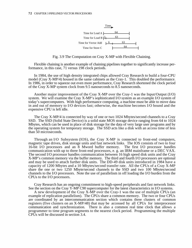
Fig. 3.9 The Computation on Cray X-MP with Flexible Chaining.
Flexible chaining is another example of chaining pipelines together to significantly increase per-formance, in this case, 71 versus 198 clock periods.
In 1984, the use of high density integrated chips allowed Cray Research to build a four-CPUmodel (Cray X-MP/4) housed in the same cabinets as the Cray-1. This doubled the performance.In 1986, in order to squeeze out even more performance, Cray Research shortened the clock periodof the Cray X-MP system clock from 9.5 nanoseconds to 8.5 nanoseconds.
Another major improvement of the Cray X-MP over the Cray-1 was the Input/Output (I/O)system. We will examine the Cray X-MP’s sophisticated I/O system as an example I/O system oftoday’s supercomputers. With high performance computing, a machine must be able to move datain and out of memory to I/O devices fast; otherwise, the machine becomes I/O bound and theexpensive CPU is left idle.
The Cray X-MP/4 is connected by way of one or two 1024 Mbytes/second channels to a CraySSD. The SSD (Solid State Device) is a solid state MOS storage device ranging from 64 to 1024Mbytes, which can be used in place of disk storage for the data of very large user programs and bythe operating system for temporary storage. The SSD acts like a disk with an access time of lessthan 50 microseconds.
Through an I/O Subsystem (IOS), the Cray X-MP is connected to front-end computers,magnetic tape drives, disk storage units and fast network links. The IOS consists of two to four16-bit I/O processors and an 8 Mword buffer memory. The first I/O processor handlescommunication with up to three front-end processors, e. g. an IBM mainframe or a DEC VAX.The second I/O processor handles communication between 16 high speed disk units and the CrayX-MP’s common memory via the buffer memory. The third and fourth I/O processors are optionaland may be used to attach further disk units. The DD-49 disk units introduced in 1984 have acapacity of 1200 Mbytes and a 10 Mbytes/second transfer rate. All the CPUs of a Cray X-MPshare the one or two 1250 Mbyte/second channels to the SSD and two 100 Mbytes/secondchannels to the I/O processors. Note the use of parallelism in off loading the I/O burden from theCPUs to the I/O processors.
Cray Research has an ongoing commitment to high-speed peripherals and fast network links.See the section on the Cray Y-MP C90 supercomputer for the latest characteristics in I/O systems.
A new development of the Cray X-MP over the Cray-1 was the use of multiple CPUs (anexample of replication parallelism). The CPUs share a common memory. The two or four CPUsare coordinated by an intercommunication section which contains three clusters of commonregisters (five clusters on an X-MP/48) that may be accessed by all CPUs for interprocessorcommunication and synchronization. There is also a common real time clock that allows aprogrammer to time program segments to the nearest clock period. Programming the multipleCPUs will be discussed in section 3.4.

3.2 More Recent Cray Supercomputers 73
Ports
ABC
I/O
Ports
ABC
I/O
CPU CPU
Crossbar Sw
itch
Crossbar Sw
itch
Common Memory - 8 Memory Banks per Section
Fig. 3.10 The Memory System for a Two-CPU Cray X-MP/2
Another consequence of multiple CPUs is a more complex memory system. Each CPU hasfour independent ports to memory which allows two loads, a store and an I/O operation to takeplace at the same time. The I/O port is reserved for the IOS and the SSD. The A, B and C portsare available for the data paths to the registers. The instruction registers must also share the fourports for fetching machine instructions. The four ports of a CPU are connected by a crossbarswitch to a section of memory containing eight interleaving memory banks (sixteen interleavedmemory banks in a four-CPU Cray X-MP/4). The crossbar switch allows any port to access anysection of memory. Figure 3.10 shows the memory system for a two-CPU Cray X-MP/2. Afour-CPU Cray X-MP/4 is similar with a crossbar switch for each CPU and sixteen interleavedmemory banks per section. Contrast this diagram with the diagram in Figure 1.10. Extrahardware is needed to resolve conflicts at the port, memory section and memory bank levels. Thissophisticated memory system achieves a high memory bandwidth of three words per clock periodper processor or 1200 Megawords/second (for a 9.5 nanosecond clock).
In scientific computing, the scatter and gather operations occur often. The scatter operation canbe defined by the following pseudo-code:
for I := 1 to NX[Index[I]] := Y[I]
endfor
which scatters values of Y arbitrarily throughout main memory according to the values in the Indexarray. Conversely, the gather operation collects the scattered elements of X and places them in theordered array as defined by the following:
for I := 1 to NY[I] := X[Index[I]]
endfor
Prior to 1984, the early Crays had no special hardware for scatter and gather operations. Suchoperations had to be done as scalar loops, with disappointing performance. In 1984, the newlyintroduced four-CPU Cray X-MP had special hardware and instructions for the implementation ofscatter and gather operations with an associated increase in speed. Cray Research introducedhardware scatter and gather partly due to market pressure from its chief competitor, the CDC 205,which had hardware scatter and gather since 1981.

74 CHAPTER 3 PIPELINED VECTOR PROCESSORS
Cray-2
While Steve Chen and his group at Cray Research were designing the X-MP/48, SeymourCray, still at Cray Research, was designing the Cray-2. Shipped in 1985, the Cray-2 is a newarchitecture with a new instruction set and operating system (Unix based). The Cray-2 is a four-CPU pipelined vector machine all contained within a cylindrical cabinet 4 feet high and 4.5 feet indiameter. The compression in size is remarkable -- in effect, a four-CPU Cray X-MP plus its I/Osystem and SSD have been shrunk to a third or a quarter of their present size and placed in a singlecontainer. The small size allows a fast clock (4.1 nanoseconds) and short signal paths (longestwire is 16 inches).
The Cray-2 uses a brand new cooling technology called liquid immersion cooling. Whereasthe older Crays used metal heat sinks and Freon piped through them to draw off the heat from thecircuit boards, all the circuit boards in the Cray-2 are totally immersed in a bath of clear, electricallyinert fluorocarbon liquid. The fluorocarbon liquid is circulated by a pump and passed through achilled water heat exchanger to extract the heat.
In the mid-1980s, computational scientists were running many large programs which exceededthe capacities of supercomputers’ main memory. They had to resort to manually transferring verylarge datasets in and out of memory to and from a fast disk. Therefore, to relieve this burden,Seymour Cray wanted the Cray-2 to have a very large common memory of 256 Megawords.However, in order to achieve such a large memory, he had to compromise the memory speed anduse, as he calls it, “PC memory” with an access time of 256 nanoseconds. In an attempt to regainthe loss in main memory speed, Seymour Cray replaced the B and T intermediate registers of theCray-1 with 16 Kwords of local memory in each processor. This local memory can be accessed infour machine cycles (16 nanoseconds). The mismatch in this two-level memory hierarchy of 256-nanosecond main memory and 16-nanosecond local memory causes performance problems. Forexample, on many programs, the Cray-2 is memory bound, i. e., the performance is limited bymemory and not by the functional units. This memory-to-CPU mismatch is the primary reason forthe Cray-2’s poor performance on the LINPACK benchmark (62 MFLOPS) shown in Figure 3.7.
The architecture of the Cray-2 is similar to the Cray-1; however, the ability to chain together asuccession of vector instructions, which is an important feature of the Cray-1 and Cray X-MP, isnot available on the Cray-2.
Cray Y-MP
Shipped in 1987, the Cray Y-MP has a similar architecture to the Cray X-MP. A majordifference is the availability of 32-bit as well as 24-bit addressing which allows main memory to belarger than 16 Megawords. Compared to the Cray X-MP, the Cray Y-MP has a faster machinecycle time (6 nanoseconds) and more processors (eight).
Cray Y-MP C90
Introduced in November, 1991, the Cray Y-MP C90 is Cray Research’s latest model high endsupercomputer. The C90 enhances the Y-MP line with twice the number of processors (16), muchlarger main memory (256 Megawords) and a faster clock (4 nanoseconds).
A new development is the introduction of two vector pipelines for each processor. This allowsfour floating-point operations per clock period for each processor. Notice that a fully configuredCRAY Y-MP C90 features 64-way replication parallelism with sixteen processors each with twovector pipes and two functional units (add and multiply) per pipe.

3.2 More Recent Cray Supercomputers 75
Each CPU has four ports to memory, each of which may read a double word (128 bits) in oneclock cycle. That is, each CPU can read eight words in one clock cycle for a total memorybandwidth of 32 Gigawords/second.
The Cray Y-MP C90 features up to 13.6 Gigabytes/second of aggregate I/O bandwidth. TheI/O subsystem supports up to 16 I/O clusters (processors) for connection to disk storage units, tapeunits and networks. Each I/O cluster can be configured with 16 DD-60 disk drives to deliver up to320 Mbytes/second performance. The DD-60 disk drives each hold 2 Gigabytes and have atransfer rate of 24 Mbytes/second. The system supports up to four 1800 Mbytes/second channelsto the SSD which may hold up to 2048 Mwords. Cray Research provides support for the veryhigh-speed networks such as HIgh-Performance Parallel Interface (HIPPI) (100 Mbytes/second)and Fiber Distributive Data Interface (FDDI) for connection to other computers.
Cray 3
In 1989, Seymour Cray left Cray Research to found another start-up company, Cray ComputerCo., where he pursues the gallium arsenide (GaAs) technology integral to the Cray-3. Cray hasdemonstrated that gallium arsenide integrated circuits can be fabricated to execute three times fasterthan silicon. The Cray-3 is to be delivered in 1992.
The Cray-3 is essentially a GaAs version of Seymour Cray’s Cray-2. However, the Cray-2memory mismatch has been solved by using much faster main memory (512 Mwords of 25nanosecond memory). Also, the computing imbalance between scalar and vector computing in theCray-2 has been removed. Scalar speed on one processor is four times that of a Cray-2 processor.
3.3 The CDC 205 SupercomputerIn 1979, Control Data Corporation reacted to Cray Research’s newly introduced Cray-1 by
completely re-engineering the CDC STAR 100 and renaming the machine the CDC 203. In 1981,after further enhancements, the machine was named the CDC 205. A pipelined vector computer,the CDC 205, the main competitor to the Cray-1, had several interesting features worth studying.
In contrast to the register-to-register style architecture of the Cray-1, the CDC 205 is amemory-to-memory vector processor. That is, rather than move a vector from memory to registerswhere it is operated on by functional units, the CDC 205 moves the vector directly from memory tothe functional unit and the resultant vector is stored back in memory. This has the major advantagethat vectors may be very long (up to 65,535 64-bit values). On the Cray-1, to operate on two longvectors, the FORTRAN compiler would generate code to compute strips of 64 elements because ofthe 64-value size limitation of the V vector registers. For example, to add two 1000 elementvectors, the Cray-1 would loop fifteen times around a body of code which includes two vectorloads, a vector add and a vector store of 64-value strips (the process is called “strip mining”).Since 1000 is not evenly divisible by 64, the compiler would generate extra code to handle the last40 elements. In contrast, the CDC 205 could perform the same vector add of two 1000 vectorelements in one instruction.
The memory-to-memory style of architecture has several consequences. First, the memorysystem becomes a very critical part of the machine. Therefore, the CDC 205 has an impressivememory system. Its 4 Mwords of memory (64-bit words) are divided into four sections each witha 512-bit wide data path. A memory access is 512-bits or a superword -- “sword” -- (eight 64-bitwords) and takes 80 nanoseconds (4 clock periods). Each of the four data paths into memory caneither read or write at the maximum rate of one superword per clock period (20 nanoseconds). Thehigh rate is obtained by interleaving 8 memory banks in each of the 1 Mword sections. The
76 CHAPTER 3 PIPELINED VECTOR PROCESSORS
memory bandwidth is therefore 400 Mwords/second per million words of memory. We note thatthis is five times the data memory bandwidth of the Cray-1 (80 Mwords/second).
A second consequence of the memory-to-memory architecture is that only a unit vectorincrement (or stride) is allowed, i. e., the values in the vector must be stored contiguously inmemory. This creates a major problem, because many scientific programs do not have a stride ofone. Consider the following FORTRAN code:
REAL A(3, 4), B(3, 4), C(3, 4)
DO 10 I = 1, 3DO 20 J = 1, 4
A(I, J) = B(I, J) + C(I, J)20 CONTINUE10 CONTINUE
In FORTRAN, arrays are stored by columns. That is, the matrix Aa1,1 a1,2 a1,3 a1,4a2,1 a2,2 a2,3 a2,4a3,1 a3,2 a3,3 a3,4
will be stored as the first column (a1,1, a2,1, a3,1), followed by the second column (a1,2, a2,2,a3,2,) and so forth. Matrix A is stored in memory as follows:
a1,1a2,1
a3,1a1,2a2,2a3,2a1,3a2,3a3,3a1,4a2,4a3,4
Now consider the sequence of indices of the above nested DO loops. The nested loops operate onthe (1, 1) elements; then the (1, 2) elements, the (1, 3) elements, the (1, 4) elements, the (2, 1)elements, etc., or every third address for a stride of three.
In this case, we can move the J DO loop inside the I DO loop (called a loop interchange) tocreate a stride of one.
REAL A(3, 4), B(3, 4), C(3, 4)
DO 20 J = 1, 4DO 10 I = 1, 3
A(I, J) = B(I, J) + C(I, J)10 CONTINUE20 CONTINUE

3.3 The CDC 205 Supercomputer 77
But in general, interchanging the DO loops won’t eliminate non-unit stride. To handle the non-unit stride situation, the CDC 205 provides several solutions. First, if the required data is notconsecutively stored, the required elements can be selected by a vector mask, one bit for each wordof the vector. The operation is then performed on elements for which the corresponding mask bitis a one. However, all elements of the consecutively stored vector must be read from memoryeven though only a small fraction may be operated upon. Second, if a non-unit stride vector is tobe operated on many times, the selected elements of the vector can be “compressed” and stored as anew temporary vector. Subsequent operations may then be performed with better efficiency on thenewly compressed vector. Third, the efficient gather and scatter operations (see page 71), whichare implemented in the hardware as microcode, may be used to form new temporary contiguouslystored vectors. Therefore, even though the CDC 205 operates effectively on very long vectors, asignificant amount of time is spent manipulating vectors to overcome the unit-stride restriction.
In contrast to the unit-stride requirement of the CDC 205, the Cray-1 allows constant stride, i.e., a vector may have elements a constant distance apart in memory. One advantage of the register-to-register architecture of the Cray-1 is that memory can fetch elements in a pattern of constantstride and store them in a V vector register before they are operated on by the functional units.However, when Seymour Cray added the 16 Kwords of local memory to the Cray 2, the Cray 2lost this important feature. On the Cray-2, vector references from local memory to the V registersmust be with unit stride. This means vectors transferred from main memory to local memory mustbe massaged on the Cray 2 much as on the CDC 205, with a similar decrease in overallperformance.
The CDC 205 has both a scalar unit and at least one vector unit which may operate in parallel.The machine may have one, two or four vector floating-point arithmetic units called pipes. If twosuccessive vector instructions use different functional units within a pipe and contain one operandthat is scalar, it is called a linked triadic (from Greek for three) operation. Several examples are:
vector + scalar * vector(vector + scalar) * vector
For a linked triad, the output stream from the first functional unit is fed to the input of the secondfunctional unit, much like chaining on the Cray-1 but more restrictive. While the CDC 205requires at least one scalar argument, on the Cray-1 all three arguments may be vectors. With alinked triad, each pipe on the CDC 205 may perform a 64-bit floating-point addition and a multiplyevery clock period (20 nanoseconds) for a rate of 100 MFLOPS. The maximum performance onthe CDC 205 is therefore 400 MFLOPS for linked triads in 64-bit arithmetic on a 4-pipe machine.It is 800 MFLOPS on 32-bit arithmetic.
Since the 4-pipe CDC 205’s peak performance of 400 MFLOPS was significantly higher thanthe Cray-1’s peak of 160 MFLOPS, it was a very attractive machine. However, the CDC 205 hasa long vector startup time as indicated by Hockney’s n1/2 parameter being 100 (for a 2-pipemachine). That is, to overcome the large vector startup time, vectors had to be more than 100elements in length to achieve half peak performance (100 MFLOPS for a 2-pipe machine). Incontrast, the Cray-1 has an n1/2 of about 10. For the 2-pipe CDC 205 (peak 200 MFLOPS) to befaster than the Cray-1, the vector lengths have to be greater than 300 [Hockney, 1988].
On the CDC 205, performance can be severely degraded at short vector lengths (less than 100)and if vectors are not stored contiguously. For this reason, scientific programmers write softwarefor the CDC 205 which employ long, contiguously stored vectors.
The successor to the CDC 205 is the ETA10 (the superscript 10 is part of the name) by ETASystems, created as a subsidiary of Control Data Corporation in 1983. The ETA10 may bedescribed as eight up-rated CDC 205 computers working from a large common memory with the

78 CHAPTER 3 PIPELINED VECTOR PROCESSORS
resultant peak performance of 10 GFLOPS. Although over 30 machines were sold, the companyran into financial problems and folded in 1989.
3.4 Influences of Pipelined Vector Processors onProgramming
This section will explore the influences of the pipelined vector processors on compiler designas well as the activity of programming.
3.4.1 Vectorization
While it is preferable to have vector constructs in high-level languages, most scientificprograms written for pipelined vector computers have been written in FORTRAN 77, which lacksvector constructs. Here we will limit our discussion to programming in FORTRAN 77, later in thebook, we will discuss the new FORTRAN 90 language which does have vector constructs.
Vectorization is the process of identifying blocks of code suitable for translation to vectorinstructions which use the high performance pipelined vector units of a vector processor, e. g.,Cray-1 or CDC 205. Basically, there are two approaches to vectorization, allow the programmerto specify which blocks of code should be vectorized or allow the compiler to determine what tovectorize. Since it is difficult for the programmer to specify what should be vectorized, mostmanufacturers have designed vectorizing compilers to handle the task automatically.
An example of a vectorizing compiler is the Cray-1’s Cray FORTRAN Translator (CFT). TheCFT FORTRAN compiler analyzes the innermost DO loops of the FORTRAN programs itcompiles to determine whether vector processing methods can be applied to improve overallprogram efficiency. If such efficiency can be improved, the compiler generates a sequence of codecontaining vector instructions to drive the high speed vector functional units. To be vectorized, aDO loop must manipulate or perform calculations on the contents of one or more arrays and nothave certain language features such as GOTO, I/O and subroutine CALL statements that inhibitvectorization. It is easy to vectorize the following block of code into a vector add.
DO 10 I = 1, NX(I) = Y(I) + Z(I)
10 CONTINUE
Other times, however, the translation is much more difficult for the compiler. Consider thefollowing code where the first seven elements of array A are 1.0, 2.0, 3.0, 4.0, 5.0, 6.0 and 7.0,respectively.
DO 10 I = 2, 7A(I) = A(I - 1)
10 CONTINUE
The results in array A differ depending on if one executes the code serially or in parallel as shownin Figure 3.11. The reader should convince himself or herself of this fact by doing the sixassignment statements of the loop in parallel.
Original Performed Performed Value Serially in Parallel
A(1) 1.0 1.0 1.0A(2) 2.0 1.0 1.0A(3) 3.0 1.0 2.0

3.4 Influences of Pipelined Vector Processors on Programming 79
A(4) 4.0 1.0 3.0A(5) 5.0 1.0 4.0A(6) 6.0 1.0 5.0A(7) 7.0 1.0 6.0
Fig. 3.11 Table Showing Results Performed Serially or in Parallel
Clearly, the parallel version is wrong because after the first iteration, each iteration of the loopdepends on the previous iteration, i. e., there exist important data dependencies. Therefore, avectorizing compiler performs an extensive dependency analysis and if a dependency is found itwill not vectorize the loop.
The following code does not have a dependency and can be vectorized.
DO 10 I = 1, 99A(I) = A(I + 1)
10 CONTINUE
Sometimes, a vectorizing compiler can not tell if the code can be vectorized or not. Forexample, if J is positive, the following code can be vectorized.
DO 10 I = 1, 99A(I) = A(I + J)
10 CONTINUE
In this case, most vectorizing compilers will print a dependency message to inform the programmerof a possible dependency, then the programmer may insert a compiler directive to vectorize theloop. Of course, if J is negative and the compiler is told to vectorize the loop, the programproduces incorrect results.
On pipelined vector computers such as the Cray-1, it is highly desirable to vectorize as muchof the program as possible. Therefore, programmers manipulate the FORTRAN code to increasethe potential of vectorization (called tuning the code). The CFT FOR-TRAN manual gives thefollowing general guidelines for vectorization:33
1. Keep subscripts simple and explicit, do not use parentheses in subscripts.
2. Do not use GOTO or CALL statements inside DO loops.
3. Use the Cray FORTRAN intrinsic functions where appropriate as they have alreadybeen tuned for vectorization.
4. Rewrite large loops containing a few unvectorizable statements as two or more loops,one or more of which will vectorize.
For an example of the last guideline, consider the following non-vectorizable code (from[Quinn, 1987]):
DO 10 I = 1, NX(I) = Y(I - 1)Y(I) = 2 * Y(I)
33 Cray X-MP and Cray-1 Computer Systems, FORTRAN Reference Manual, SR-0009, Cray Research, Inc., 1986,p. 9-18.

80 CHAPTER 3 PIPELINED VECTOR PROCESSORS
10 CONTINUE
However, the following set of two DO loops is functionally equivalent and both are vectorizable.
DO 10 I = 1, NY(I) = 2 * Y(I)
10 CONTINUEDO 20 I = 1, N
X(I) = Y(I - 1)20 CONTINUE
Sometimes, there is more than one way to vectorize a block of code and the compiler mustdetermine which way has the potential for the highest performance. For example, it is better forthe length of the vector to be as long as possible. Many vectorizing compilers will perform a loopinterchange source transformation on the following code:
DO 10 I = 1, 100DO 20 J = 1, 10
A(I, J) = B(I, J) * C(I, J)20 CONTINUE10 CONTINUE
to the following code with a longer vector in the inner loop.
DO 20 J = 1, 10DO 10 I = 1, 100
A(I, J) = B(I, J) * C(I, J)10 CONTINUE20 CONTINUE
Because of this potential of loop interchange by a vectorizing compiler, programmers should avoidplacing GOTO and CALL statements in all DO loops not just the inner most ones.
Vectorizing compilers have become very sophisticated in their attempts to vectorize code. SeeMichael Wolfe’s book on Optimizing Supercompilers for Supercomputers [Wolfe, 1989] for moredetail. The CFT compiler is enhanced all the time, particularly, the optimization phase of thecompiler which vectorizes the code. For example, in 1978, CFT on the Cray-1 was rated at 4.7MFLOPS on the Lawrence Livermore Loops benchmark. In 1984 on the same benchmark andmachine, the compiler generated code which performed 11.1 MFLOPS.
3.4.2 Programming Multiple CPUs
As an example of programming on multiple CPUs, we will discuss the approach used on theCray computers.
With the introduction of multiple CPUs on the Cray X-MP in 1984, Cray Research providedsystem routines to allow the CPUs to cooperate in the solution of single user programs. Thisfacility is called multi-tasking by Cray. On the Cray X-MP and later model Crays, the unit ofwork, called a task, that is handed for execution on a CPU is a FORTRAN subroutine, preferablyone that must compute for a while. A task is started by a call to the TSKSTART system routine.
CALL TSKSTART(taskid, name of subroutine, list of parameters)
Effectively a fork operation, the call to TSKSTART defines a logical CPU, i. e., a concurrentprocess, which is put into a process queue for later execution. The actual physical CPU theprocess will execute on is chosen by the multi-tasking system software and can’t be specified by

3.4 Influences of Pipelined Vector Processors on Programming 81
the programmer. This has the advantage that multi-tasking programs written for the Cray X-MPdo not have to be aware of the number of CPUs available or how busy they are. Thecorresponding join operation is accomplished by a call to the TSKWAIT system routine
CALL TSKWAIT(taskid)
which makes the parent program wait until the task identified by taskid has terminated. Therefore,TSKWAIT functions as a synchronization point for the several tasks.
Below is an example multi-tasking program in CFT FORTRAN to spread a vector add overtwo CPUs:
PROGRAM ADDCOMMON/GLOBAL/ A(1000), B(1000), C(1000)INTEGER TASKID(2)EXTERNAL ADDHALFDATA B/1000*1.0/, C/1000*2.0/TASKID(1) = 2N = 1000
C start up child task to compute upper half of vectorCALL TSKSTART(TASKID, ADDHALF, N/2 + 1, N)
C have parent compute lower half of vector addCALL ADDHALF(1, N/2)
C have the parent wait for child task to terminateCALL TSKWAIT(TASKID)
C ... other stuffSTOPEND
SUBROUTINE ADDHALF(N1, N2)COMMON/GLOBAL/ A(10000, B(1000), C(1000)DO 10 I = N1, N2
A(I) = B(I) + C(I)10 CONTINUE
RETURNEND
Here the two tasks -- the one initiated by TSKSTART and the main program -- are independentand no intertask communication is required. Since the Cray X-MP is a shared memory machine,intertask communication is achieved by sharing variables by way of a global COMMON area. Themulti-tasking software provides locks (semaphores) for critical regions of code, specifically, theuse of these variables shared by several tasks. For example, to update the shared variableCOUNT , each task would surround the update with a call to LOCKON and LOCKOFF as in thefollowing:
CALL LOCKON(LOCK3)COUNT = COUNT + 1CALL LOCKOFF(LOCK3)
where LOCK3 is an integer variable assigned to and identifying the lock.
Therefore, to utilize multi-CPUs on the Cray X-MP, the programmer must manually partitionthe code into subroutines which are forked off as concurrent tasks. The programmer is responsiblefor identifying any commonly shared variables used by the tasks and protecting those sections ofcode which use the shared variables with locks. Also, the programmer is responsible for balancingthe amount of computation between concurrent tasks to minimize the idle time of CPUs.

82 CHAPTER 3 PIPELINED VECTOR PROCESSORS
Multi-tasking on the Cray X-MP has some costs. First, the calls to the TSKSTART,TSKWAIT, LOCKON and LOCKOFF routines take time and there is system overhead associatedwith the multi-tasking system to coordinate and schedule the tasks. However, for someapplications, multi-tasking is effective in gaining higher performance.

3.4 Influences of Pipelined Vector Processors on Programming 83
Chapter 3 Exercises1. Discuss the differences between a register-to-register architecture and a memory-to-memoryarchitecture.
2. In the context of this chapter, what is strip mining?
3. The ABC computer has a pipelined CPU which can produce a floating point add and a multiplyevery clock period (8 nanoseconds). What memory bandwidth is needed for a typical arithmeticoperation?
4. For the computer in problem 3, assume you have available lots of 80 nanosecond memory.Design a memory system which can achieve the memory bandwidth you computed in problem 3.5. Vector computers usually have the ability to mask selected elements in a vector. Why is suchmasking needed in a vector computer?
6. Given vector A = {1.0, 2.0, 3.0, 4.0, 5.0} and masking vector M = {10010}. What is theresult of the compress instruction using A and M as arguments?
7. What is the stride of the following FORTRAN code?
REAL X(3,7)
DO 10 I = 1, 7X(2, I) = 4.0
10 CONTINUE
8. Why is stride important on vector computers?
9. What is the vector length used by a arithmetic pipeline in the following code? How could youimprove the vector length?
DO 30 K1 = 1, 64DO 50 K2 = 10, 20
C(K1 + 7, K2) = 5.0 * D(K1, K2)50 CONTINUE30 CONTINUE
10. If your application had mostly vectors of 50 elements long, would you execute the program ona Cray-1 or a CDC 205. Justify your answer.
11. In some sort algorithms, the array values needed to be moved (permuted) correspond to the bit-reversal (i. e., flip the binary value horizontally) of the index. For example, if the index is 4 (100in binary), move the value to 1 (001 in binary) and the value at 1 (001 in binary) is moved to 4.Show how to use the scatter and/or gather operations to generate this bit reversal. Give an exampleusing a 16 element array.
12. On the CDC 205, a linked triadic operation has double the performance compared to a simpletwo argument vector operation. Why? Also, why is n1/2 almost the same for the two cases?