Embed Size (px)
Citation preview
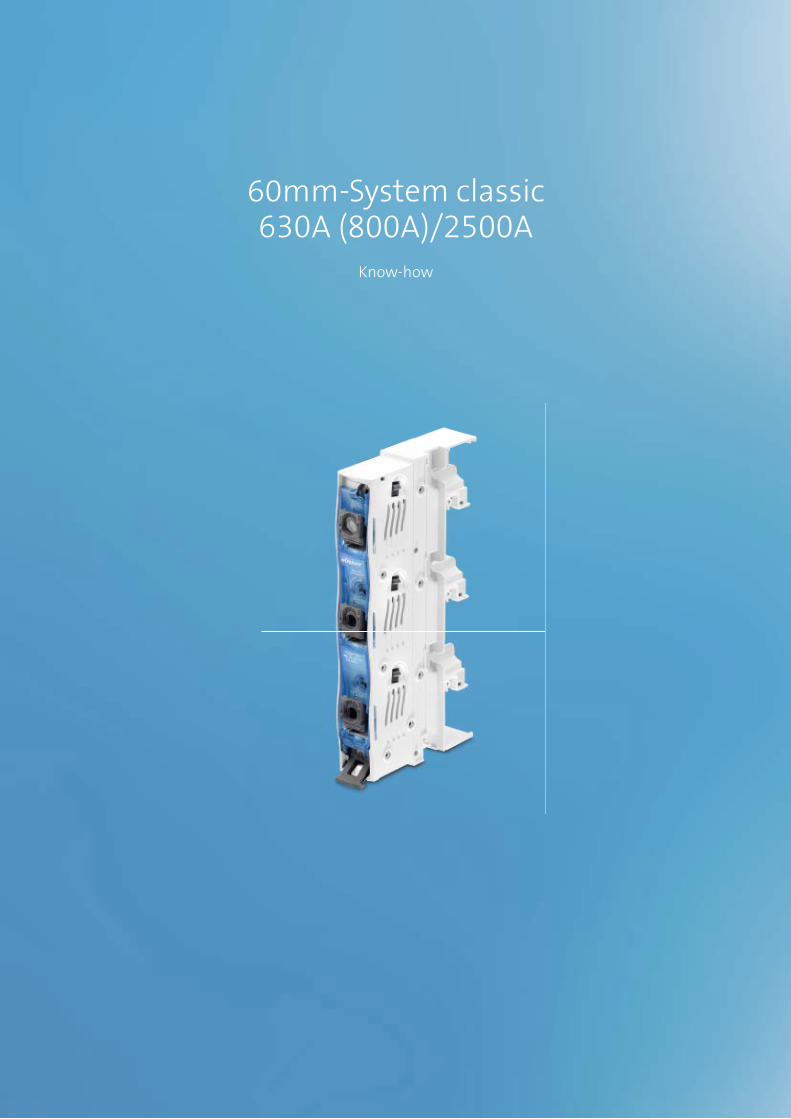
60mm-System classic 630A (800A)/2500A
Know-how

2

2
System advantagesThe 60mm busbar system classic enables a broad or wide range of busbars to be used, and therefore offers easy adaptation to suit a great variety of currents. The hall-mark of this system is its especially safe, space-saving and simple design, not to mention its very extensive choice of components. In addition, many components of the 60mm-System classic satisfy the through-air and over-surface arcing distances distances as per UL 508. They are therefore suitable for use in North America. You can find detailed information about this in the Appro-val Overview on page 8/57 onwards, and in the Product Descriptions on the internet at www.woehner.com.
Connection technologyConductors with a cross-section of up to 300mm2 can be connected without drilling to universal conductor terminals or terminal plates. Uncut conductors can also be connected to terminal plates, for connecting multiple busbar systems, for example. With the jaw-type termin als of the CRITO®ProfiClip, circular and sector-shaped cond uctors can be connected quickly and con- veniently. End-to-end busbar connections enable busbar systems to be extend ed effortlessly.
MOTUS®ContactronControlHybrid motor starter with additional functions: direct and reversing starters, overload protection and safety-oriented switch-off. The compact design with a width of just 22.5mm saves space in the control cabinet. Integra-ted functions simplify the wiring considerably. Further-more, service life is extended by the hybrid switching technology: the lifespan is up to 10x greater than in con-ventional switchgear such as contactors. The broad range adjustment also reduces the number of variants: just 3 versions are required for settings from 0.075A to 9A. With CrossLink® adapter for the 60mm-System classic, power is fed through the busbar system. The adapter locks securely in place on the busbar. The busbars remain safely covered and out of reach even if the MOTUS® basic devices are removed. Suitable for use around the world, with with UL508 approval for the North American market as well.
EQUES®TechnologyAdapter technology in the 60mm system: With numerous innovative features, the EQUES®EasyConnector, the EQUES®PowerConnector and the EQUES®MotorController reliably connect busbars of 12 x 5mm to 30 x 10mm and double-T and triple-T sections up to 2500A. With its dual mounting feature, the EQUES®MotorController opens up new areas of application, with considerably greater safety. The busbar still offers shock protection while switch - gear is being replaced. Moreover, new versions of the EQUES®PowerConnector now offer the option of connect-ing 4-pole circuit breakers directly to the busbar system.
SECUR®EasyLiner
Switch disconnector with D0 fuses
Flat design
SnapLock technology: Tool-free connection using spring-loaded terminals
Captive drawer for holding adapter sleeve and fuse link
NEW
EQUES®ControlSystem
SmartWire DT® module
3 inputs and 2 outputs
For activating motor circuit breakers and contactor assemblies
For plugging into any EQUES adapter up to 80A
260mm-System classic630A (800A) / 2500A
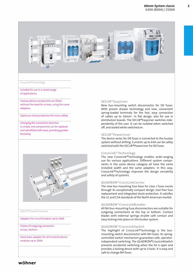
SECUR®EasyLinerNew bus-mounting switch disconnector for D0 fuses. With proven drawer technology and new, convenient spring-loaded terminals for the fast, easy connection of cables up to 16mm2. In fl at design, also for use in distribution boards. The SECUR®EasyLiner switches inde-pendently of the user. It can be isolated when switched off , and sealed while switched on.
SECUR®PowerLinerThe device series for D0 fuses is connected to the busbar system without drilling. Currents up to 63A can be safely switched with the SECUR®PowerLiner for D0 fuses.
CrossLink®TechnologyThe new CrossLink®Technology enables wide-ranging use for various applications. Diff erent system compo-nents in the same device category all have the same installed width and the same adapters. In this way, CrossLink®Technology improves the design versatility and safety of systems.
QUADRON®CrossLinkCarrierThe new bus-mounting fuse base for class J fuses excels through its exceptionally compact design, tool-free fuse replacement and integrated shock protection. It satisfi es the UL and CSA standards of the North American market.
QUADRON®CrossLinkBreakerAll NH bus-mounting fuse disconnectors are suitable for outgoing connections at the top or bottom. Contact blades with external springs enable safe contact and easy locking into place on the busbar system.
QUADRON®CrossLinkSwitchThe highlight of CrossLink®Technology is the bus- mounting switch disconnector with NH fuses. Its spring-controlled switch mechanism guarantees safe, operator-independent switching. The QUADRON®CrossLinkSwitch prevents accidental switching when the lid is open and provides a locking device with up to 3 locks. It is easy and safe to change NH fuses.
CrossLink®Technology
Suitable for use in a varied range of applications
Various device components are fi tted without the need for screws, using the same adapters
Optimum shock protection for more safety
Changing the connection direction is simple, and components can be replaced and retrofi tted with ease, providing greater fl exibility
EQUES®PowerConnector
Adapters for circuit breakers up to 160A
Choice of outgoing connection at top / bottom
Same basic adapter for all CrossLink device modules up to 200A

01 48501 13101 48401 35601 601 01 50001 50801 49501 573
2/1
Universal busbar supportsType For busbars Pack size Weight Part no.
kg/100 u.2-pole with internal screw holes 12, 20, 30 x 5, 10 1 8.3 01 602 063-pole with internal screw holes 12, 15, 20, 25, 30 x 5, 10 10 12.7 01 495 063-pole with additional external screw holes 12, 15, 20, 25, 30 x 5, 10 10 13.7 01 500 064-pole with internal screw holes 12, 15, 20, 25, 30 x 5, 10 10 26.6 01 485 06
UL busbar supports3-pole with internal screw holes 12, 20, 30 x 5, 10 10 14.0 01 508 06spacer, fits under 01 508 10 9.1 01 358 064-pole with internal screw holes 12, 20, 30 x 5, 10 10 19.7 01 357 06spacer, fits under 01 357 10 13.1 01 359 06
Base plate for UL busbar supports 01 508, 01 231, 01 232Type Pack size Weight Part no.
kg/100 u.240 x 1100 2 73.7 01 518 06240 x 700 2 46.9 01 515 06
PE/N busbar supports, including PE and N labelsType For busbars Pack size Weight Part no.
kg/100 u.2-pole, indiv. mountable * 12, 15, 20, 25, 30 x 5, 10 10 9.5 01 356 061-pole, indiv. mountable 12, 20, 30 x 5, 10 1 5.9 01 601 06* Busbars at different heights and depths
Connection busbar support3-pole, with integrated terminals 1.5 - 16mm² 12, 15, 20, 25, 30 x 5, 10 10 25.6 01 484 06
End cover, for covering busbar endsType Pack size Weight Part no.
kg/100 u.for busbar support 01 602 1 1.5 01 363 06for busbar supports 01 495, 01 500, 01 508 and 01 484 10 2.0 01 573 06for busbar supports 01 357 and 01 485 5 5.6 01 131 06
Designation for ULApprovals 8 57 - 66 Technical data 8 6
Dimensions 9 5,6
12
PHB2014_EN.indb 1 10.02.2014 15:44:28

01 61801 62301 62001 62201 625
2/2
Busbar E-CU, flat busbars, tin-platedType Length Cross section Pack size Weight Part no.
kg/100 u.12 x 5 2400 60 1 128.4 01 618 0615 x 5 2400 75 1 160.6 01 619 0620 x 5 2400 100 1 214.4 01 620 0625 x 5 2400 125 1 267.8 01 621 0630 x 5 2400 150 1 321.4 01 622 0612 x 10 2400 120 1 257.0 01 623 0620 x 10 3600 200 1 650.0 01 140 06
2400 200 1 428.6 01 624 0630 x 10 3600 300 1 970.0 01 204 06
2400 300 1 643.2 01 625 06Shorter lengths on request For current carrying capacity of busbars see page 8/7 or 8/8
Designation for ULApprovals 8 57 - 66 Technical data 8 7
260mm-System classic 630A (800A) / 2500A
2
GD_PG_$KT-PHB2014-$KP-60MMCLASSIC-$PG-22_#SEN_#APR_#V1.indd 2 13.02.2014 14:55:11

01 232 01 42201 23101 132 01 11601 234
2/3
Busbar supports, for double-T section, without end coverType Pack size Weight Part no.
kg/100 u.1-pole, for connection to 01 231 and individually mountable 4 13.0 01 116 063-pole, with internal screw holes 3 59.1 01 231 06
Busbar supports, for triple-T section, without end cover1-pole, for connection to 01 232 and individually mountable 4 15.0 01 132 063-pole, with internal screw holes 2 69.7 01 232 06
Busbar supports, for TCC section, without end cover3-pole with internal screw holes 2 69.7 01 422 06
End coverfor busbar supports 01 116 and 01 132 4 1.8 01 373 06for busbar supports 01 231 and 01 232 4 4.8 01 234 06for busbar support 01 422 4 5.3 01 425 06
Designation for ULApprovals 8 57 - 66 Technical data 8 6
Dimensions 9 6,7
32
PHB2014_EN.indb 3 10.02.2014 15:44:35

01 22401 60801 19001 22701 610
2/4
Busbar E-CU, section busbars tin-platedType Length Cross section Pack size Weight Part no.
kg/100 u.Double-T section busbars 500mm² 3600 500 1 1596.0 01 224 06
2400 500 1 1062.0 01 609 06Double-T section busbars 720mm² 3600 720 1 2334.0 01 190 06
2400 720 1 1554.0 01 608 06Triple-T section busbars 1140mm² 3600 1140 1 3693.6 01 227 06
2400 1140 1 2462.4 01 187 06TCC section busbars 1600mm² 2400 1600 1 3416.0 01 610 06Shorter lengths on request For current carrying capacity of busbars see page 8/7 or 8/8
Busbar E-CU, section busbars plainDouble-T section busbars 500mm² 3600 500 1 1596.0 01 223 06
2400 500 1 1060.0 01 250 06Double-T section busbars 720mm² 3600 720 1 2332.0 01 229 06
2400 720 1 1556.0 01 249 06Shorter lengths on request For current carrying capacity of busbars see page 8/7 or 8/8
Designation for ULApprovals 8 57 - 66 Technical data 8 8
Dimensions 9 25,26
460mm-System classic 630A (800A) / 2500A
2
PHB2014_EN.indb 4 10.02.2014 15:44:39

01 55501 55401 13601 02501 23701 02601 252
2/5
Busbar cover, 1m longType Pack size Weight Part no.
kg/100 u.for 12 - 30 x 5 busbar 10 8.7 01 244 06for 12 - 30 x 10 busbar 10 10.1 01 245 06for double-T and triple-T section 5 38.0 01 252 06for 12 x 5 busbar 10 3.2 78 463 06independent of the system, for individual busbars
Cover section, 3-pole0.7m long, can only be used with mount 01 026 or 01 320 2 75.0 01 025 06mount, 32mm depth, for cover section 01 025 10 3.9 01 026 06mount, 107mm depth, for cover section 01 025, can be combined with 01 237, 01 238
8 12.0 01 320 06
for systems with 12 - 30 x 5/10mm busbars, double-T and triple-T section
System cover, 3-poleholder set (left + right) for cover sections, 3-pole 1 18.0 01 136 07front cover section (3-pole), 1.1m long, only with holder 01 136 1 45.1 01 554 07top/bottom cover section, 1.1m long, only with holder 01 136 or 01 137 2 27.1 01 555 07top/bottom cover section, slotted, 1.1m long, only with holder 01 136 or 01 137
2 23.0 01 417 07
can be used for systems with 12, 15, 20, 25, 30 x 5/10 busbars, double-T and triple-T section
System cover, 4-poleholder set (left + right) for cover sections, 4-pole 1 21.0 01 137 07front cover section (4-pole), 1.1m long, only with holder 01 137 1 58.0 01 599 07top/bottom cover section, 1.1m long, only with holder 01 136 or 01 137 2 27.1 01 555 07top/bottom cover section, slotted, 1.1m long, only with holder 01 136 or 01 137
2 23.0 01 417 07
can be used for systems with 12, 15, 20, 25, 30 x 5/10 busbars, double-T and triple-T section
Compartment section, for adjusting the installation depth in double-T and triple-T busbar systems48mm deep, 2.4m long 1 70.0 01 236 0676mm deep, 2.4m long 1 105.0 01 237 06106mm deep, 2.4m long 1 140.0 01 238 06
Designation for ULApprovals 8 57 - 66 Technical data 8 4
Dimensions 9 6,7,8,9
52
PHB2014_EN.indb 5 10.02.2014 15:44:42

01 53701 75401 24301 24001 56301 484
2/6
Connection busbar supportType For busbars Pack size Weight Part no.
kg/100 u.3-pole, with integrated terminals 1.5 - 16mm² 12, 15, 20, 25, 30 x 5, 10 10 25.6 01 484 06
CRITO®ProfiLiner, connection module 3-pole, for 12, 15, 20, 25, 30 x 5, 10 with spring terminals, with cover capConnection Width For use Pack size Weight Part no.
up to max. kg/100 u.1.5 - 16mm2 20 80A 8 18.1 01 563 07
Connecting terminal plate, 3-pole, for 12 x 5 - 30 x 10 and double-T and triple-T section, with cover cap6 - 50mm², rm, f, f +AE, la. Cu 7x4 to 9x10 54 300A 1 45.1 01 240 0735 - 120mm², rm, f, f +AE, la. Cu 12x4 to 15,5x10 81 440A 1 53.5 01 243 07
AccessoriesType Pack size Weight Part no.
kg/100 u.additional individual cover for the terminals in 01 240 3 0.4 01 300 07additional individual cover for the terminals in 01 243 3 0.5 01 301 07
Connecting terminal plate, 3-pole, for 20 x 5 - 30 x 10 and double-T and triple-T section, with cover capConnection Width For use Pack size Weight Part no.
up to max. kg/100 u.Cu and Al 95 - 185mm², rm, sm, f * 135 460A 1 132.2 01 199 07Cu and Al 120 - 300mm², rm, sm, f * 135 560A 1 165.7 01 754 07for la. Cu 20x3 to 32x15 ** 135 800A 1 144.7 01 753 07* not maintenance-free if aluminium conductors are used (see page 8/2)** observer minimum terminal space (see page 8/10)
Connection set, 3-pole, for 20 x 5 - 30 x 10 and double-T and triple-T section, without cover capCu and Al 120 - 300mm², rm, sm, f * 153 560A 1 155.5 01 537 07for flat busbars up to 32 x 20 153 800A 1 132.5 01 538 07* not maintenance-free if aluminium conductors are used (see page 8/2)
Connection set, 4-pole, for 20 x 5 - 30 x 10 and double-T and triple-T section, without cover capCu and Al 120 - 300mm², rm, sm, f * 204 560A 1 210.0 01 147 07for flat busbars up to 32 x 20 204 800A 1 180.0 01 162 07* not maintenance-free if aluminium conductors are used (see page 8/2)
Designation for ULApprovals 8 57 - 66 Technical data 8 10
Dimensions 9 5,9,10
660mm-System classic 630A (800A) / 2500A
2
PHB2014_EN.indb 6 10.02.2014 15:44:46

01 07101 07001 06901 75901 31801 29201 29001 289
2/7
Universal conductor terminalfor busbars Connection Terminal space For use Pack size Weight Part no.
min. - max. W x H up to max. kg/100 u.5mm flat busbars 1.5 - 16 7.5 x 7.5 180A 100 2.1 01 284 07
4 - 35 10.5 x 11 270A 50 4.6 01 285 0716 - 70 14 x 14 400A 25 7.1 01 287 07
16 - 120 17 x 15 440A 25 10.6 01 068 0710mm flat busbars 1.5 - 16 7.5 x 7.5 180A 100 2.3 01 289 07
4 - 35 10.5 x 11 270A 50 4.7 01 290 0710mm flat busbars, double-T andtriple-T section
16 - 70 14 x 14 400A 25 7.5 01 292 0716 - 120 17 x 15 440A 25 10.9 01 203 07
CRITO®ProfiClip, brace terminalsfor busbars Connection For use Pack size Weight Part no.
up to max. kg/100 u.12-20 x 5-10 Cu & Al 35-150mm², rm, f, f+AE 480A 6 10.2 01 135 0720-30 x -10, double-T and triple-T section
for flat busbars up to 30 x 20 750A 6 30.3 01 319 07Cu and Al 95 - 185mm², rm, sm, f 500A 6 31.2 01 318 07
for flat busbars up to 32 x 20 800A 3 34.7 01 759 07Cu and Al 120 - 300mm², rm, sm, f 600A 3 42.5 01 760 07
01 318 and 01 760: not maintenance-free if aluminium conductors are used* not maintenance-free if aluminium conductors are used (see page 8/2)
CRITO®PowerClip, brace terminals for the connection of flat busbars and laminated copperfor busbars Terminal space Side Centre Pack size Weight Part no.
W x H supply supply kg/100 u.30 x 10 and double-T and triple-T section
55 x 10 - 28 1600A 2000A 3 50.0 01 069 0768 x 10 - 28 1600A 2000A 3 63.0 01 070 07
105 x 10 - 28 1600A 2800A 3 84.0 01 071 07
Cover cap, 3-pole, can also be used as reserve section coverType for busbars Pack size Weight Part no.W x H x D kg/100 u.54 x 200 x 55 12-30 x 5-10, double-T and triple-T section 1 14.7 01 590 0784 x 200 x 55 12-30 x 5-10, double-T and triple-T section 10 14.9 01 413 07135 x 200 x 90 20-30 x -10, double-T and triple-T section 1 29.5 01 756 07180 x 200 x 90 12-30 x 5-10, double-T and triple-T section 1 33.0 01 539 07228 x 200 x 90 12-30 x 5-10, double-T and triple-T section 1 37.3 01 596 07250 x 200 x 90 12-30 x 5-10, double-T and triple-T section 1 39.3 01 540 07270 x 200 x 90 20-30 x -10, double-T and triple-T section 1 64.7 01 757 07
Cover cap, 4-pole, can also be used as reserve section cover228 x 260 x 90 12-30 x 5-10, double-T and triple-T section 1 45.0 01 597 07
Designation for ULApprovals 8 57 - 66 Technical data 8 9,12
Dimensions 9 8-11
72
PHB2014_EN.indb 7 10.02.2014 15:44:47

01 20201 99601 74901 74801 747
2/8
Clip-on screw connector, for cable lugs DIN 46 234Type Terminal space For use Pack size Weight Part no.
up to max. kg/100 u.for undrilled flat busbars, 5mm thick M5 x 8 360A 25 4.8 01 747 07
M8 x 8 490A 20 16.0 01 748 07M10 x 10 630A 6 35.8 01 749 07
for undrilled flat busbars, 10mm thick M5 x 8 360A 25 5.0 01 512 07for undrilled flat busbars, 10mm thick and double-T and triple-T section
M8 x 8 490A 20 16.5 01 514 07M10 x 10 630A 6 36.2 01 047 07
Busbar connector, to connect flat busbars and la. CuTerminal space Terminal space Pack size Weight Part no.W x L max. height kg/100 u.25 x 20 20 10 14.9 01 996 0730 x 20 20 10 16.2 01 997 0730 x 30 20 10 19.8 01 586 0735 x 30 20 10 21.5 01 587 0740 x 20 20 10 17.8 01 206 0740 x 32 20 6 27.6 01 616 07
Busbar connection, along length with wedge clamp terminalFor busbars Round cond. Flat cond. Pack size Weight Part no.
min. - max. W x H kg/100 u.20 x 5 - 10 120 - 240 21 x 4 - 20 3 11.0 01 201 0725 x 5 150 - 300 25 x 5 - 20 3 13.4 01 202 07
Busbar connection,along length with brace terminal, for la. Cu30 x 10 and double-T and triple-T section - 32 x 1 - 15 3 50.0 01 069 07
Designation for ULApprovals 8 57 - 66 Technical data 8 11
Dimensions 9 11,12
860mm-System classic 630A (800A) / 2500A
2
PHB2014_EN.indb 8 10.02.2014 15:44:52

01 90701 90601 18501 04701 09201 51401 094
2/9
Profile terminal, for double-T section busbarsConnection cross section Terminal space Side Centre Pack size Weight Part no.
W x H supply supply kg/100 u.320 - 800mm² 41 x 20 - 42 1600A 1600A 3 67.0 01 185 07500 - 750mm² 51 x 5 - 28 1600A 1600A 3 70.5 01 906 07600 - 900mm² 64 x 5 - 28 1600A 1600A 3 84.0 01 907 07500 - 1000mm² 51 x 20 - 42 1600A 2000A 3 73.5 01 936 07600 - 1200mm² 64 x 20 - 42 1600A 2000A 3 85.9 01 911 07800 - 1600mm² 81 x 20 - 42 1600A 2500A 3 101.1 01 934 071000 - 2000mm² 101 x 20 - 42 1600A 2800A 3 113.7 01 935 07for the connection of flat busbars and laminated copper busbars
Profile terminal, for triple-T section busbars320 - 800mm² 41 x 23 - 45 1600A 1600A 3 105.0 01 513 07500 - 1260mm² 64 x 23 - 45 2000A 2500A 3 124.0 01 008 071200 - 3600mm² 101 x 23 - 45 2500A 3200A 3 172.7 01 186 07for the connection of flat busbars and laminated copper busbars
CRITO®PowerClip, brace terminals for busbars 30 x 10 and section busbars30 x 10 and double-T andtriple-T section
55 x 10 - 28 1600A 2000A 3 50.0 01 069 0768 x 10 - 28 1600A 2000A 3 63.0 01 070 07
105 x 10 - 28 1600A 2800A 3 84.0 01 071 07for the connection of flat busbars and laminated copper busbars
TerminalFor busbars Connection For use Pack size Weight Part no.
up to max. kg/100 u.30 x -10 and double-T andtriple-T section
95 - 300 630A 3 85.7 01 094 07for flat busbars up to 40 x 25 1250A 3 81.7 01 092 07
Laminated copper busbars, Cu blank, insulated, length 2mDimensions Rated current 50K Cross section Pack size Weight Part no.
kg/100 u.10 x 40 x 1 1053A 400 1 746.0 01 615 0610 x 50 x 1 1244A 500 1 932.0 01 509 0610 x 63 x 1 1481A 630 1 1180.0 01 510 0610 x 80 x 1 1777A 800 1 1490.0 01 061 0610 x 100 x 1 2110A 1000 1 1870.0 01 273 06further cross sections see page 7/7 and 7/8
Designation for ULApprovals 8 57 - 66 Technical data 8 12
Dimensions 9 10,27
92
PHB2014_EN.indb 9 10.02.2014 15:44:53

01 82701 14501 82901 90501 36130 322
2/10
Busbar connector, for same-size busbarsFor busbars Length System spacing For use Pack size Weight Part no.
up to max. kg/100 u.12-20 x 5-10 55 5 - 10 520A 12 19.2 01 166 07
150 100 - 110 520A 3 52.4 01 193 0720-30 x 5-10 40 9 - 20 630A 6 23.3 01 990 07
40 13 - 20 630A 6 25.2 01 823 0795 50 - 60 630A 3 54.4 01 141 07
150 100 - 110 630A 3 86.6 01 886 07Double-T section 50 9 - 20 1600A 6 49.4 01 827 07
95 50 - 60 1600A 3 94.3 01 145 07150 100 - 110 1600A 3 146.1 01 829 0770 5 - 10 1600A 3 113.9 01 905 07
Triple-T section 95 50 - 60 2500A 3 120.6 01 274 07150 100 - 110 2500A 3 178.0 01 275 07
3 units required for a 3-pole connection, use 01 026 or 01 320 and 01 025 as a cover (see page 2/5). the use of the UL phase separator sets below is essential for UL-compliant end-to-end busbar connection.
UL phase separator set for busbar connectors, 3-poleType Width Pack size Weight Part no.
kg/100 u.for connections 01 166, 01 990, 01 823, 01 827 * 105 1 17.2 01 360 06for connections 01 141, 01 145, 01 274 * 145 1 19.6 01 361 06for connections 01 193, 01 886, 01 829, 01 275 200 1 21.8 01 362 06* each depth dimension has to be cut to size
Connection set, 3-pole, for section busbarsType For use Pack size Weight Part no.
up to max. kg/100 u.for a flexible connection, double-T section * 1600A 1 536.0 30 322 07for a flexible corner coupling, double-T section * 1600A 1 638.0 30 473 07for a flexible connection, triple-T section * 2500A 1 940.0 01 295 07* one set is required for a 3-pole connection
Designation for ULApprovals 8 57 - 66 Technical data 8 11
Dimensions 9 12
1060mm-System classic 630A (800A) / 2500A
2
PHB2014_EN.indb 10 10.02.2014 15:44:57

32 42132 41632 40432 400
2/11
EQUES®MotorControllerWith removable upper section. Base remains shock-protected on the busbar system.All adapters for busbars 12, 15, 20, 30 x 5, 10; section busbars
EQUES®MotorController 32A, busbar adapter, with removable upper section, with AWG 10 (6mm2) leads2 mounting rails 54 200 4 49.2 32 404 052 mounting rails 54 260 4 54.4 32 408 05
EQUES®MotorController 45A, busbar adapter, with removable upper section, with AWG 8 (10mm2) leads2 mounting rails 54 200 4 52.9 32 412 052 mounting rails 54 260 4 56.7 32 416 05
EQUES®MotorController empty,busbar adapter, with removable upper section, without electrical contact2 mounting rails 45 200 4 34.9 32 420 052 mounting rails 54 200 4 38.8 32 421 052 mounting rails 45 260 4 36.2 32 425 052 mounting rails 54 260 4 42.1 32 426 05side module, connectable on both sides 9 200 10 4.3 32 964 05
EQUES®ControlSystem module for connection to SmartWire-DT®For all EQUES adapters in the 60mm-System classic up to 80A, 3 inputs, 2 outputs 1 8.0 36 230 21Further components for SmartWire-DT on page 7/2
Accessories for EQUES®Technologymounting rail 45mm 10 1.4 32 947 05mounting rail 54mm 10 1.5 32 948 05mounting rail 63mm 10 1.8 32 949 05mounting rail 72mm 10 2.0 32 950 05mounting rail 81mm 10 2.1 32 951 05mounting rail end stop 50 0.1 32 969 05connecting element, universal 50 0.1 32 954 058-pole connector, with support, 250V 10 3.4 32 511 0510-pole connector, with support, 250V 10 4.0 32 513 05micro switch for EMC 10 0.9 32 956 05
Designation for ULApprovals 8 57 - 66 Technical data 8 13,16
Dimensions 9 13
11
EQUES®MotorController 16A, busbar adapter, with removable upper section, with AWG 14 (2.5mm2) leadsType Adapter Adapter Pack size Weight Part no.
width length kg/100 u.16A, 2 mounting rails, leads 2.5mm², 125 long 45 200 4 42.7 32 401 05
EQUES®MotorController 25A, busbar adapter, with removable upper section, with AWG 12 (4mm2) leads2 mounting rails 45 200 4 42.7 32 400 052 mounting rails 45 260 4 45.0 32 402 05
2
PHB2014_EN.indb 11 10.02.2014 15:45:02

32 47232 45932 44332 44232 43932 432 32 430
2/12
EQUES®EasyConnectorDevices can be directly mounted on 12, 15, 20, 25, 30 x 5 and 10 busbars, and section busbars
EQUES®EasyConnector 25A, busbar adapter with leads AWG 12 (4mm2)Type Adapter Adapter Pack size Weight Part no.
width length kg/100 u.1 mounting rail 45 200 4 32.5 32 430 052 mounting rails 45 200 4 32.6 32 431 052 mounting rails 90 200 2 57.1 32 432 052 mounting rails 45 260 4 35.7 32 433 05
EQUES®EasyConnector 25A, busbar adapter with 6mm2 connection terminals, without leads2 mounting rails 45 200 4 32.2 32 436 052 mounting rails 45 260 4 35.2 32 439 05UL terminal cap for 32 436 and 32 439 45 15 4 0.7 32 973 05
EQUES®EasyConnector 32A, busbar adapter with leads AWG 10 (6mm2)1 mounting rail 45 200 4 33.3 32 655 051 mounting rail 54 200 4 36.6 32 441 052 mounting rails 54 200 4 38.0 32 442 051 mounting rail 63 200 4 44.5 32 443 051 mounting rail 72 200 4 44.3 32 444 052 mounting rails 81 200 4 49.5 32 446 052 mounting rails 54 260 4 43.3 32 449 05
EQUES®EasyConnector 63A, busbar adapter with leads AWG 8 (10mm2)1 mounting rail 54 200 4 39.2 32 454 052 mounting rails 54 200 4 41.0 32 455 051 mounting rail 63 200 4 44.9 32 456 051 mounting rail 72 200 4 47.6 32 457 052 mounting rails 81 200 4 51.3 32 459 052 mounting rails 54 260 4 43.0 32 461 05
EQUES®EasyConnector 80A, busbar adapter with 16mm2 connection terminals, without leads1 mounting rail 54 200 4 37.3 32 466 052 mounting rails 54 200 4 38.9 32 467 051 mounting rail 72 200 4 45.0 32 469 052 mounting rails 54 260 4 43.8 32 472 05UL terminal cap for 32 466, 32 467, 32 469 and32 472
54 15 4 0.8 32 974 05
Designation for UL Accessories 2 13Approvals 8 57 - 66 Technical data 8 13
Dimensions 9 13
1260mm-System classic 630A (800A) / 2500A
2
PHB2014_EN.indb 12 10.02.2014 15:45:04

32 47732 48632 46432 48532 48732 465
2/13
EQUES®EasyConnectorDevices can be directly mounted on 12, 15, 20, 25, 30 x 5 and 10 busbars, and section busbars
EQUES®EasyConnectorType Mounting Adapter Adapter Pack size Weight Part no.
rails width length kg/100 u.32A, special type with spring terminal 1.5-6mm2
at front1 45 200 4 32.5 32 486 052 45 260 4 35.5 32 487 05
80A, special type with screw terminal 1.5-16mm2
at front1 54 200 4 37.3 32 464 052 54 260 4 41.2 32 465 05
EQUES®EasyConnector empty, busbar adapter without electrical contactsuniversal 2 45 200 4 24.8 32 477 05universal 2 54 200 4 27.7 32 478 05universal 2 45 260 4 27.9 32 484 05universal 2 54 260 4 38.5 32 485 05side module, connectable on both sides 9 200 10 2.3 32 963 05
PE/N adapter module, with 16 mm2 terminals, top and bottom, without leadscan be connected on both sides, only for use with EQUES adapter 18 242 4 14.1 32 146 05
Accessories for EQUES®TechnologyType Pack size Weight Part no.
kg/100 u.mounting rail 45mm 10 1.4 32 947 05mounting rail 54mm 10 1.5 32 948 05mounting rail 63mm 10 1.8 32 949 05mounting rail 72mm 10 2.0 32 950 05mounting rail 81mm 10 2.1 32 951 05mounting rail end stop 50 0.1 32 969 05connecting element, universal 50 0.1 32 954 058-pole connector, with support, 250V 10 3.4 32 511 0510-pole connector, with support, 250V 10 4.0 32 513 05Lead AWG 14 (2.5mm²), 105mm long * 24 0.3 32 921 05Lead AWG 10 (6mm²), 130mm long * 24 0.7 32 907 05Lead AWG 4 (25mm²), 210mm long * 24 5.1 32 914 05Double-lead 2 x AWG 10 (2 x 6mm²), 130 / 280mm long * 24 2.5 32 915 05* Both lead ends ultrasound compressed
Bus module EQUES®ControlSystem for SmartWire-DTTM
bus modul SmartWire-DT 1 8.0 36 230 21further components for SmartWire-DT on page 7/2
Designation for ULApprovals 8 57 - 66 Technical data 8 13,16
Dimensions 9 13
132
PHB2014_EN.indb 13 10.02.2014 15:45:08

32 46032 42832 44832 53432 533 32 45032 440
2/14
EQUES®EasyConnectorDevices can be directly mounted on 12, 15, 20, 25, 30 x 5 and 10 busbars, and section busbars
EQUES®EasyConnector 16A, busbar adapter with leads AWG 14 (2.5mm2)Type Mounting Adapter Adapter Pack size Weight Part no.
rails width length kg/100 u.for direct/reversing starters with spring terminal connection Allen-Bradley 140M-RC2E, Eaton PKZM0, Siemens S00, Schneider Electric GV2
2 45 200 4 31.0 32 429 05
for direct / reversing starters with spring terminals Allen-Bradley 140M-RC2E, Eaton PKZM0, Siemens S00, Schneider Electric GV2
2 90 200 2 57.0 32 440 05
EQUES®EasyConnector 25A, busbar adapter with leads AWG 12 (4mm2)for direct starter Eaton PKZ0/BG1 1 45 200 4 33.0 32 450 05for reversing starter Eaton PKZ0/BG1 1 90 200 2 54.6 32 452 05for direct starter Siemens S00 with screw connection
1 45 200 4 33.0 32 445 05
for direct starter Siemens S00 with spring terminal connection
1 45 260 4 30.7 32 637 05
for reversing starter Siemens S00 with screw connection
1 90 200 2 54.1 32 448 05
EQUES®EasyConnector 32A, busbar adapter with leads AWG 10 (6mm2)for direct starter ABB MS116/132 2 45 200 4 36.4 32 498 05for direct starter Eaton PKZ0/BG2 2 45 200 4 36.4 32 451 05for reversing starter Eaton PKZ0/BG2 2 90 200 2 61.2 32 453 05for direct starter Allen-Bradley 140MC/D 2 45 200 4 32.5 32 533 05for reversing starter Allen-Bradley 140M-C/D 2 54 200 4 38.0 32 534 05for direct starter Schneider Electric GV2-M/P 2 45 200 4 33.3 32 434 05for direct starter Schneider Electric GV2-M/P 2 45 260 4 36.2 32 438 05for direct starter Schneider Electric LUB12/32 1 45 200 4 32.2 32 427 05for reversing starter Schneider Electric LU2B12/32 1 45 260 4 35.1 32 428 05for direct starter Siemens S0 with screw connection
1 45 260 4 33.3 32 639 05
for direct starter Siemens S0 with spring terminal connection
1 45 260 4 32.1 32 638 05
for direct starter Siemens S0 with spring terminal connection
1 45 200 4 32.1 32 659 05
for direct starter Siemens 3RA6 1 45 200 4 44.0 32 588 05
EQUES®EasyConnector 63A, busbar adapter with leads AWG 8 (10mm2)for direct starter ABB MS45x, Eaton PKZM4, Siemens S2
2 55 260 4 43.2 32 460 05
for direct starter Allen-Bradley 140M-F 2 54 200 4 43.0 32 535 05for direct starter ABB MS45x and Eaton PKZ5 2 72 260 4 51.4 32 463 05
Designation for ULApprovals 8 57 - 66 Technical data 8 13
Dimensions 9 13
1460mm-System classic 630A (800A) / 2500A
2
PHB2014_EN.indb 14 10.02.2014 15:45:10
32 15732 14032 57032 575
2/15
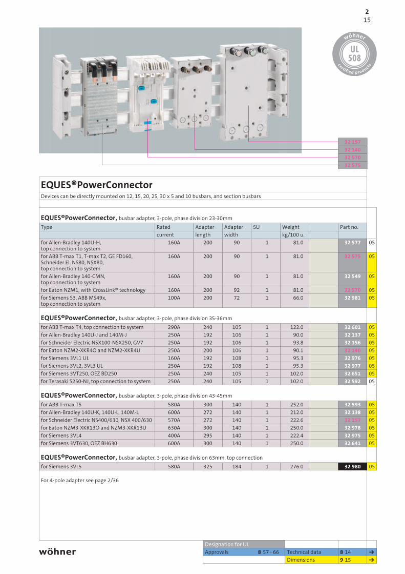
EQUES®PowerConnectorDevices can be directly mounted on 12, 15, 20, 25, 30 x 5 and 10 busbars, and section busbars
EQUES®PowerConnector, busbar adapter, 3-pole, phase division 23-30mmType Rated Adapter Adapter SU Weight Part no.
current length width kg/100 u.for Allen-Bradley 140U-H, top connection to system
160A 200 90 1 81.0 32 577 05
for ABB T-max T1, T-max T2, GE FD160, Schneider El. NS80, NSX80,top connection to system
160A 200 90 1 81.0 32 575 05
for Allen-Bradley 140-CMN,top connection to system
160A 200 90 1 81.0 32 549 05
for Eaton NZM1, with CrossLink® technology 160A 200 92 1 81.0 32 570 05for Siemens S3, ABB MS49x,top connection to system
100A 200 72 1 66.0 32 981 05
EQUES®PowerConnector, busbar adapter, 3-pole, phase division 35-36mmfor ABB T-max T4, top connection to system 290A 240 105 1 122.0 32 601 05for Allen-Bradley 140U-J and 140M-J 250A 192 106 1 90.0 32 137 05for Schneider Electric NSX100-NSX250, GV7 250A 192 106 1 93.8 32 156 05for Eaton NZM2-XKR4O and NZM2-XKR4U 250A 200 106 1 90.1 32 140 05for Siemens 3VL1 UL 160A 192 108 1 95.3 32 976 05for Siemens 3VL2, 3VL3 UL 250A 192 108 1 95.3 32 977 05for Siemens 3VT250, OEZ BD250 250A 240 105 1 102.0 32 651 05for Terasaki S250-NJ, top connection to system 250A 240 105 1 102.0 32 592 05
EQUES®PowerConnector, busbar adapter, 3-pole, phase division 43-45mmfor ABB T-max T5 580A 300 140 1 252.0 32 593 05for Allen-Bradley 140U-K, 140U-L, 140M-L 600A 272 140 1 212.0 32 138 05for Schneider Electric NS400/630, NSX 400/630 570A 272 140 1 222.6 32 157 05for Eaton NZM3-XKR13O and NZM3-XKR13U 630A 300 140 1 250.0 32 978 05for Siemens 3VL4 400A 295 140 1 222.4 32 975 05for Siemens 3VT630, OEZ BH630 600A 300 140 1 250.0 32 641 05
EQUES®PowerConnector, busbar adapter, 3-pole, phase division 63mm, top connectionfor Siemens 3VL5 580A 325 184 1 276.0 32 980 05
Designation for ULApprovals 8 57 - 66 Technical data 8 14
Dimensions 9 15
For 4-pole adapter see page 2/36
152
PHB2014_EN.indb 15 10.02.2014 15:45:14

32 98232 00432 16832 214
2/16
Universal busbar adapterAll adapters for 12 - 30 x 5 - 10 busbars and section busbars
Busbar adapter up to 250AType Adapter Adapter Pack size Weight Part no.
length width kg/100 u.200A top connection to system 222 108 1 84.2 32 214 05200A bottom connection to system 222 108 1 86.0 32 215 05250A top connection to system 320 110 1 160.4 32 168 05250A bottom connection to system 320 110 1 164.0 32 216 05for all commercially available switchgear with M4 fixing screws (see accessories for M5 screws)
Accessories for universal busbar adaptersM5 slide nut for 32 214, 32 215, 32 168 and 32 216 4 0.4 32 937 05
Busbar adapter 630Ascrew M10 top or bottom 320 184 1 278.0 32 004 05Metal accessory plate, adjustable 315 180 1 82.0 32 982 05
Approvals 8 57 - 66 Technical data 8 14New Dimensions 9 14
1660mm-System classic 630A (800A) / 2500A
2
PHB2014_EN.indb 16 10.02.2014 15:45:21

36 20936 10836 10536 10236 114
2/17
MOTUS®ContactronControl
MOTUS®ContactronControl, Hybrid motor starter with reversing function and CrossLink®Technology, 22.5mm wideType Pack size Weight Part no.
kg/100 u.0.075 - 0.6A direct/reversing starter 1 62.6 36 102 210.18 - 2.4A direct/reversing starter 1 62.6 36 105 211.5 - 9A direct/reversing starter 1 62.6 36 108 21
Module for connection to SmartWire-DT®for all MOTUS®ContactronControl 1 6.5 36 209 21further components for SmartWire-DT on page 7/2
Spare components MOTUS®ContactronControl16A fuse for 0.6A and 2.4A versions 3 2.8 31 567 2120A fuse for 9A version 3 2.8 31 568 2130A fuse for 9A version for motors with heavy starting 3 2.8 31 569 210.075 - 0.6A electronics module for direct/reversing starters 1 57.1 36 109 210.18 - 2.4A electronics module for direct/reversing starters 1 57.1 36 110 211.5 - 9A electronics module for direct/reversing starters 1 57.1 36 111 21adapter for 60mm-System classic 1 11.0 36 114 21
Designation for UL Accessories 7 1,2Approvals 8 57 - 66 Technical data 8 15,16
Dimensions 9 16
172
PHB2014_EN.indb 17 10.02.2014 15:45:25
31 07131 07231 07031 44231 44131 91931 91831 95131 95031 94731 946
2/18
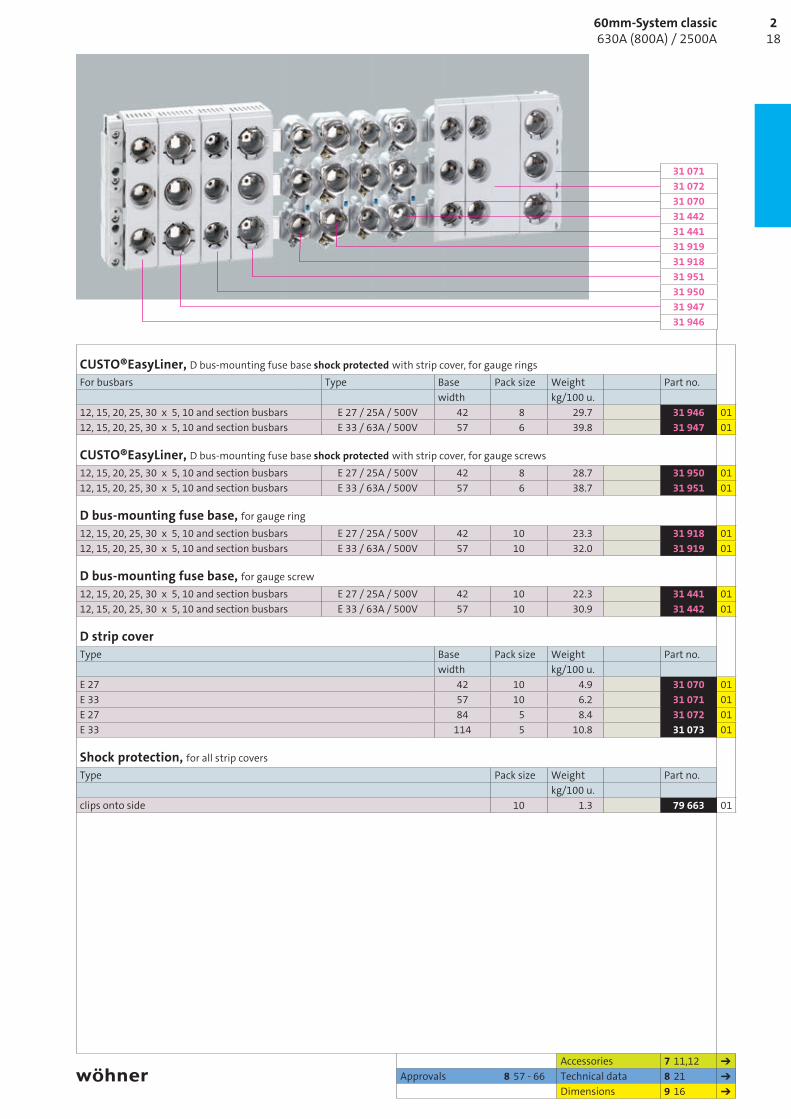
CUSTO®EasyLiner, D bus-mounting fuse base shock protected with strip cover, for gauge ringsFor busbars Type Base Pack size Weight Part no.
width kg/100 u.12, 15, 20, 25, 30 x 5, 10 and section busbars E 27 / 25A / 500V 42 8 29.7 31 946 0112, 15, 20, 25, 30 x 5, 10 and section busbars E 33 / 63A / 500V 57 6 39.8 31 947 01
CUSTO®EasyLiner, D bus-mounting fuse base shock protected with strip cover, for gauge screws12, 15, 20, 25, 30 x 5, 10 and section busbars E 27 / 25A / 500V 42 8 28.7 31 950 0112, 15, 20, 25, 30 x 5, 10 and section busbars E 33 / 63A / 500V 57 6 38.7 31 951 01
D bus-mounting fuse base, for gauge ring12, 15, 20, 25, 30 x 5, 10 and section busbars E 27 / 25A / 500V 42 10 23.3 31 918 0112, 15, 20, 25, 30 x 5, 10 and section busbars E 33 / 63A / 500V 57 10 32.0 31 919 01
D bus-mounting fuse base, for gauge screw12, 15, 20, 25, 30 x 5, 10 and section busbars E 27 / 25A / 500V 42 10 22.3 31 441 0112, 15, 20, 25, 30 x 5, 10 and section busbars E 33 / 63A / 500V 57 10 30.9 31 442 01
D strip coverType Base Pack size Weight Part no.
width kg/100 u.E 27 42 10 4.9 31 070 01E 33 57 10 6.2 31 071 01E 27 84 5 8.4 31 072 01E 33 114 5 10.8 31 073 01
Shock protection, for all strip coversType Pack size Weight Part no.
kg/100 u.clips onto side 10 1.3 79 663 01
Accessories 7 11,12Approvals 8 57 - 66 Technical data 8 21
Dimensions 9 16
1860mm-System classic 630A (800A) / 2500A
2
PHB2014_EN.indb 18 10.02.2014 15:45:28

31 15801 98101 42401 98001 49801 64731 93631 935
2/19
SECUR®PowerLiner, bus-mounting switch disconnector with fuses, 3-pole, 3-pole switchingType Rated current / Pack size Weight Part no.
Rated voltage kg/100 u.for D01 and D02 fuses * 63 A / 400 V 1 75.9 31 158 01for 10 x 38mm NFC cylinder fuses IEC 60 269-2 32A / 690V 1 76.0 31 232 01Convertible to 1-pole switching.* The use of side module 31 901 is recommended for continuous loads above 35A. Please observe DIN EN 61,439-2 table 101.
SECUR®PowerLiner, bus-mounting switch disconnector with fuses, with LED, 3-pole, 3-pole switchingfor D01 and D02 fuses * 63A / 400V 1 76.5 31 525 01convertible to 1-pole switching.* The use of side module 31 901 is recommended for continuous loads above 35A. Please observe DIN EN 61,439-2 table 101.
Accessories, for SECUR®EasyLinerpilot switch 1 0.7 31 903 019mm side module 5 6.1 31 901 01D02 reducer for D01 fuses 2-16A 20 0.1 31 902 01
CUSTO®EasyLiner, D0 bus-mounting fuse base shock protected with strip cover, for gauge ringBusbars Type Base Pack size Weight Part no.
width kg/100 u.12, 15, 20, 25, 30 x 5, 10 and section busbars * E 18 / 63A / 400V 27 8 14.4 31 935 01
E 18 / 63A / 400V 36 6 16.1 31 936 01* 36mm wide type provides good lead placement and heat dissipation
D0 bus-mounting fuse base, for gauge ring12, 15, 20, 25, 30 x 5, 10 and section busbars * E 18 / 63A / 400V 27 10 14.7 01 647 01
E 18 / 63A / 400V 36 10 15.5 01 498 01* 36mm wide type provides good lead placement and heat dissipation
D0 strip coverType Base Pack size Weight Part no.
width kg/100 u.E 18 27 10 2.6 01 980 01E 18 36 10 3.1 01 424 01E 18 54 10 4.0 01 981 01
Shock protection, for all strip coversType Pack size Weight Part no.
kg/100 u.clips onto side 10 1.3 79 663 01
Accessories 7 9,10Approvals 8 57 - 66 Technical data 8 18,20
Dimensions 9 16
192
PHB2014_EN.indb 19 10.02.2014 15:45:33
33 07531 57931 57801 13831 57531 574
2/20
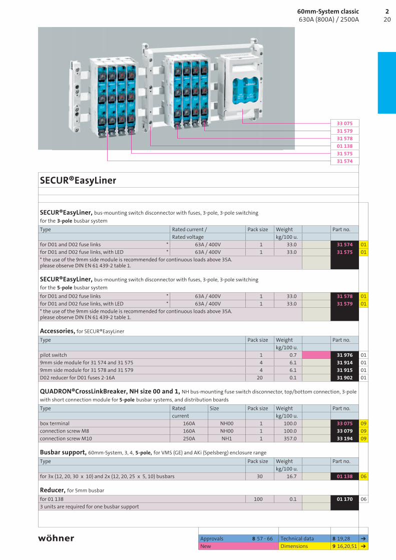
SECUR®EasyLiner
SECUR®EasyLiner, bus-mounting switch disconnector with fuses, 3-pole, 3-pole switching for the 3-pole busbar systemType Rated current / Pack size Weight Part no.
Rated voltage kg/100 u.for D01 and D02 fuse links * 63A / 400V 1 33.0 31 574 01for D01 and D02 fuse links, with LED * 63A / 400V 1 33.0 31 575 01* the use of the 9mm side module is recommended for continuous loads above 35A.please observe DIN EN 61 439-2 table 1.
SECUR®EasyLiner, bus-mounting switch disconnector with fuses, 3-pole, 3-pole switching for the 5-pole busbar systemfor D01 and D02 fuse links * 63A / 400V 1 33.0 31 578 01for D01 and D02 fuse links, with LED * 63A / 400V 1 33.0 31 579 01* the use of the 9mm side module is recommended for continuous loads above 35A.please observe DIN EN 61 439-2 table 1.
Accessories, for SECUR®EasyLinerType Pack size Weight Part no.
kg/100 u.pilot switch 1 0.7 31 976 019mm side module for 31 574 and 31 575 4 6.1 31 914 019mm side module for 31 578 and 31 579 4 6.1 31 915 01D02 reducer for D01 fuses 2-16A 20 0.1 31 902 01
QUADRON®CrossLinkBreaker, NH size 00 and 1, NH bus-mounting fuse switch disconnector, top/bottom connection, 3-pole with short connection module for 5-pole busbar systems, and distribution boardsType Rated Size Pack size Weight Part no.
current kg/100 u.box terminal 160A NH00 1 100.0 33 075 09connection screw M8 160A NH00 1 100.0 33 079 09connection screw M10 250A NH1 1 357.0 33 194 09
Busbar support, 60mm-System, 3, 4, 5-pole, for VMS (GE) and AKi (Spelsberg) enclosure rangeType Pack size Weight Part no.
kg/100 u.for 3x (12, 20, 30 x 10) and 2x (12, 20, 25 x 5, 10) busbars 30 16.7 01 138 06
Reducer, for 5mm busbarfor 01 138 100 0.1 01 170 063 units are required for one busbar support
Approvals 8 57 - 66 Technical data 8 19,28New Dimensions 9 16,20,51
2060mm-System classic 630A (800A) / 2500A
2
PHB2014_EN.indb 20 10.02.2014 15:45:36

31 96331 95531 95831 96031 570
2/21
AMBUS®EasyLinerFuse holderDevices can be directly mounted on 12, 15, 20, 25, 30 x 5 and 10 busbars, and section busbars
AMBUS®EasyLiner, bus-mounting fuse base, 1-pole, 1-pole isolatingType Can be Rated current Width Pack size Weight Part no.
used with Rated voltage kg/100 u.for fuses 10 x 38 IEC 60 269-6
30 x 5/10 30A / 1000V DC 22.5 12 5.0 31 570 0120 x 5/10 30A / 1000V DC 22.5 12 5.0 31 572 01
AMBUS®EasyLiner, bus-mounting fuse base, 2-pole, 2-pole isolating, with spring terminalsfor fuses 10 x 38 IEC 60 269-2
12, 15, 20, 25 and
30 x 5 or 10
32A / 690V 27 6 12.2 31 961 0120A / 1000V DC 27 6 12.2 31 956 01
for fuses 10 x 38 IEC 60 269-6, with LED 400-1000V DC
20A / 1000V DC 27 6 12.2 31 960 01
AMBUS®EasyLiner, bus-mounting fuse base, 3-pole, 3-pole isolating, with spring terminalsfor fuses 10 x 38 IEC 60 269-2
12, 15, 20, 25 and
30 x 5 or 10
32A / 690V 27 4 18.5 31 954 01
for fuses 10 x 38 IEC 60 269-2, with LED 110-690V AC/DC
32A / 690V 27 4 18.7 31 955 01
for fuses Class CC UL 248-4
30A / 600V 27 4 18.6 31 958 01
for fuses Class CC UL 248-4, with LED 110-600V AC/DC
30A / 600V 27 4 18.8 31 959 01
AMBUS®EasyLiner, bus-mounting fuse base, 3-pole + N, all-pole isolating, with spring terminalsfor fuses 10 x 38 IEC 60 269-2 12, 15, 20, 25
and30 x 5 or 10
32A / 690V 27 4 25.2 31 963 01for fuses 10 x 38 IEC 60 269-2, with LED 110-690V AC/DC
32A / 690V 27 4 25.2 31 964 01
SECUR®PowerLiner, bus-mounting switch disconnector with fuses, 3-pole, 3-pole switchingType Rated current / Pack size Weight Part no.
Rated voltage kg/100 u.for 10 x 38mm NFC cylinder fuses IEC 60 269-2 32A / 690V 1 76.0 31 232 01
Designation for ULApprovals 8 57 - 66 Technical data 8 17
Dimensions 9 16,32
Fuses are not included in delivery
212
PHB2014_EN.indb 21 10.02.2014 15:45:40

2/2222
60mm-System classic 630A (800A) / 2500A
2
PHB2014_EN.indb 22 10.02.2014 15:45:41

33 32433 19833 40203 19932 594
2/23
CrossLink® Technology, module width 106Devices can be directly mounted on 12, 15, 20, 25, 30 x 5 and 10 busbars, and section busbars
QUADRON®CrossLinkCarrier NH, bus-mounting fuse base, bottom/top connection, 3-poleType Rated Size Pack size Weight Part no.
current kg/100 u.box terminal 160A NH00 1 87.0 03 199 10connection screw M8 160A NH00 1 87.0 03 299 10with shock protection, without grip lug covers; for further NH bus-mounting fuse bases see pages 2/31 and 3/7
QUADRON®CrossLinkCarrier Class J, bus-mounting fuse base, bottom/top connection, 3-polebox terminal 30A Class J 30A 1 138.0 33 421 16box terminal 60A Class J 60A 1 135.0 33 422 16box terminal * 100A Class J 100A 1 129.0 33 402 16* do not use any fuse links with sharp-edged contact blades
QUADRON®CrossLinkBreaker NH, bus-mount. fuse switch disconnector, bottom/top connection, 3-polebox terminal 160A NH00 1 100.0 33 198 09connection screw M8 160A NH00 1 103.0 33 398 09box terminal, electronic fuse monitoring 160A NH00 1 117.0 33 324 09connection screw M8, electronic fuse monitoring
160A NH00 1 117.0 33 394 09
box terminal, electro-mechanical fuse monitoring
160A NH00 1 180.0 33 206 09
connection screw M8,electro-mechanical fuse monitoring
160A NH00 1 180.0 33 420 09
NH bus-mounting fuse switch disconnector size 00, with short connection module for 5-pole busbar systems, and distribution boards see page 2/20 and 7/3
QUADRON®CrossLinkAdapter, busbar adapter, 3-pole, phase division 33mmType Adapter Adapter Pack size Weight Part no.
length width kg/100 u.for system components with module width 106mm;to be used as spare slot mounting, busbar cover
200 106 2 36.5 32 594 09
Designation for UL Accessories 7 13-22Approvals 8 57 - 66 Technical data 8 25-30
Dimensions 9 17,18,20
232
PHB2014_EN.indb 23 10.02.2014 15:45:46

33 91133 50333 54033 50633 500
2/24
CrossLink® Technology, module width 106Devices can be directly mounted on 12, 15, 20, 25, 30 x 5 and 10 busbars, and section busbars
QUADRON®CrossLinkSwitch NH, bus-mounting switch disconnector with fuses, 3-pole, with multifunctional handle (spring-controlled switch mechanism)Type Rated Size Pack size Weight Part no.
current kg/100 u.bottom connection, box terminal 125 A NH00 1 219.0 33 500 15top connection, box terminal 125 A NH00 1 219.0 33 501 15bottom connection, box terminal, electronic fuse monitoring, 690V AC, 250V DC
125 A NH00 1 236.0 33 506 15
circuit diagram for fuse monitoring on page 9/40
QUADRON®CrossLinkSwitch NH, bus-mounting switch disconnector with fuses, 3-pole, for door coupling twist handle (spring-controlled switch mechanism)bottom connection, box terminal, front drive 125 A NH00 1 208.0 33 503 15top connection, box terminal, front drive 125 A NH00 1 208.0 33 504 15additional extension shaft and door coupling twist handle required Further QCS for door coupling twist handle with side actuation on request
QUADRON®CrossLinkSwitch, bus-mounting switch disconnector, 3-pole, with multifunctional handle (spring-controlled switch mechanism)Type Rated Pack size Weight Part no.
current kg/100 u.bottom connection, box terminal * 160A 1 216.0 33 540 14top connection, box terminal * 160A 1 216.0 33 541 14* as main switch or emergency stop switch only with the following maximum operating current: 125A/690V AC
QUADRON®CrossLinkSwitch, bus-mounting switch disconnector, 3-pole for door coupling drive (spring-controlled switch mechanism)bottom connection, box terminal, front drive * 160A 1 208.0 33 543 14top connection, box terminal, front drive * 160A 1 208.0 33 544 14additional extension shaft and door coupling twist handle required* As main switch or emergency stop switch only with the following maximum operating current: 125A/690V AC
Accessories 7 13,14Approvals 8 57 - 66 Technical data 8 32-34
Dimensions 9 22
Fuses are not included in delivery
2460mm-System classic 630A (800A) / 2500A
2
PHB2014_EN.indb 24 10.02.2014 15:45:50

33 32533 601 33 40303 30032 595
2/25
CrossLink® Technology, module width 184Devices can be directly mounted on 12, 15, 20, 25, 30 x 5 and 10 busbars, and section busbars
QUADRON®CrossLinkCarrier, NH bus-mounting fuse base, bottom/top connection, 3-poleType Rated Size Pack size Weight Part no.
current kg/100 u.box terminal 250A NH1 1 210.5 03 300 10connection screw M10 250A NH1 1 198.5 03 301 10with shock protection, without grip lug covers; for further NH bus-mounting fuse bases see pages 2/32 and 3/7
QUADRON®CrossLinkCarrier, bus-mounting fuse base Class J, bottom/top connection, 3-polewedge clamp terminal AWG 2-MCM300 * 200A Class J 200A 1 278.0 33 403 16* do not use any fuse links with sharp-edged contact blades
QUADRON®CrossLinkBreaker, NH bus-mounting fuse switch disconnector, bottom/top connection, 3-polebox terminal 250A NH1 1 266.0 33 600 09connection screw M10 250A NH1 1 266.0 33 601 09connection screw M10, electronic fuse monitoring 250A NH1 1 223.0 33 325 09connection screw M10,electro-mechanical fuse monitoring
250A NH1 1 333.0 33 160 09
QUADRON®CrossLinkAdapter, busbar adapter, 3-pole, phase division 57mmType Adapter Adapter Pack size Weight Part no.
length width kg/100 u.for system components with module width 184mm;to be used as spare slot mounting, busbar cover
210 184 2 75.5 32 595 09
Designation for UL Accessories 7 13-22Technical data 8 25-30Dimensions 9 17,18,21
252
PHB2014_EN.indb 25 10.02.2014 15:45:55

33 91133 51333 55033 51633 511
2/26
QUADRON®CrossLinkSwitch, module width 184Devices can be directly mounted on 12, 15, 20, 25, 30 x 5 and 10 busbars, and section busbars
QUADRON®CrossLinkSwitch NH, bus-mounting switch disconnector with fuses, 3-pole, with multifunctional handle (spring-controlled switch mechanism)Type Rated Size Pack size Weight Part no.
current kg/100 u.bottom connection, connection screw M10 250A NH1 1 567.0 33 510 15top connection, connection screw M10 250A NH1 1 589.0 33 511 15top connection, connection screw M10,electronic fuse monitoring
250A NH1 1 625.0 33 516 15
circuit diagram for fuse monitoring on page 9/40
QUADRON®CrossLinkSwitch NH, bus-mounting switch disconnector with fuses, 3-pole, for door coupling drive (spring-controlled switch mechanism)bottom connection, connection screw M10 250A NH1 1 555.0 33 513 15top connection, connection screw M10 250A NH1 1 577.0 33 514 15additional extension shaft and door coupling twist handle required QCS for door coupling twist handle with side actuation on request
QUADRON®CrossLinkSwitch, bus-mounting switch disconnector, 3-pole, with multifunctional handle (spring-controlled switch mechanism)Type Rated Pack size Weight Part no.
current kg/100 u.bottom connection, connection screw M10 * 320A 1 565.0 33 550 14top connection, connection screw M10 * 320A 1 587.0 33 551 14* as main switch or emergency stop switch only with the following maximum operating current: 280A/400V AC, 250A/690V AC
QUADRON®CrossLinkSwitch, bus-mounting switch disconnector, 3-pole for door coupling drive (spring-controlled switch mechanism)bottom connection, connection screw M10 * 320A 1 543.0 33 553 14top connection, connection screw M10 * 320A 1 565.0 33 554 14additional extension shaft and door coupling twist handle required* as main switch or emergency stop switch only with the following maximum operating current: 280A/400V AC, 250A/690V AC
Accessories 7 13,14Technical data 8 32-34Dimensions 9 23,24
Fuses are not included in delivery
2660mm-System classic 630A (800A) / 2500A
2
PHB2014_EN.indb 26 10.02.2014 15:46:01

33 156 33 914 33 908 33 911
2/27
Accessories, module width 106for CrossLink® Technology
for QUADRON®CrossLinkCarrier NH, bus-mounting fuse base, 3-poleType Size Pack size Weight Part no.
kg/100 u.aux. conductor connection for box term. 00 3 0.6 33 915 09grip lug cover, 1 unit required for each fuse 00 30 1.2 79 448 10cover, for cable lugs, can be clipped on top and bottom 00 1 2.8 79 811 09wedge clamp terminal for screw connection M8, Cu and Al cond. 16-70mm² rm, sm, f, f +AE
* 00 3 3.0 33 224 09
tunnel terminal for screw connection M8, Cu 3 x 1.5-16mm2 rm, Cu 3 x 1.5-10mm2 f + AE
00 3 6.4 01 182 09
* not maintenance-free if aluminium conductors are used (see page 8/2)
for QUADRON®CrossLinkBreaker, NH bus-mounting fuse switch disconnector, 3-poleaux. conductor connection for box term. 00 3 0.6 33 915 09cover, for cable lugs, can be clipped on top and bottom 00 1 2.8 79 811 09wedge clamp terminal for screw connection M8, Cu and Al cond. 16-70mm² rm, sm, f, f +AE
* 00 3 3.0 33 224 09
tunnel terminal for screw connection M8, Cu 3 x 1.5-16mm2 rm, Cu 3 x 1.5-10mm2 f + AE
00 3 6.4 01 182 09
pilot switch for monitoring lid position 000, 00, 2, 3 1 1.1 33 156 09lid interlock for sealing wire 00 10 0.2 03 849 09* not maintenance-free if aluminium conductors are used (see page 8/2)
for QUADRON®CrossLinkSwitch, NH bus-mounting switch disconnector with fuses and bus-mounting switch disconnector, 3-poleType Can be Pack size Weight Part no.
used with kg/100 u.aux. conductor connection for box term. QCS-NH00
QCS 1603 0.6 33 915 09
connection terminal 120mm² 3 12.1 33 914 14pilot switch, for monitoring the switch position 1 1.1 33 908 14door coupling twist handle, black, IP 66, lockable in 'off' position, with up to 3 padlocks, door locking can be activated, no extension shaft
* 33 503 33 504 33 543 33 544 33 580
1 57.0 33 910 14
door coupling twist handle, red-yellow, IP 66, lockable in 'off' position, with up to 3 padlocks, door locking can be activated, no extension shaft
* 1 57.0 33 911 14
ext. shaft 290mm long 1 13.0 33 912 14ext. shaft 490mm long 1 22.0 33 913 14* switch can also be installed at a 90° angle to left/right, with the handle in the same position
Technical data 8 26-34Dimensions 9 23,38,41
272
PHB2014_EN.indb 27 10.02.2014 15:46:05

33 142 33 145 33 909 33 910
2/28
Accessories, module width 184for CrossLink® Technology
for QUADRON®CrossLinkCarrier, NH bus-mounting fuse base, 3-poleType Size Pack size Weight Part no.
kg/100 u.cover, for cable lugs, can be clipped on top/bottom 1 2 10.7 33 142 09grip lug cover, 3 units are needed for an NH fuse base 1 3 2.5 33 916 10
for QUADRON®CrossLinkCarrier, NH bus-mounting fuse base, 3-polecover, for cable lugs, can be clipped on top/bottom 1 2 10.7 33 142 09pilot switch, for monitoring disconnector lid position 1 1 1.3 33 917 09disconnector lid interlock for 3 locks with a shackle diameter of 4-7mm / sealing wire
1-3 10 0.5 33 157 09
barrier for handle for closing of handle area from rear 1-3 10 2.2 33 155 09arc chamber, retrofit package for higher utilisation category 1 3 10.7 33 918 09
for QUADRON®CrossLinkSwitch, NH bus-mounting switch disconnector with fuses and bus-mounting switch disconnector, 3-poleType Can be Pack size Weight Part no.
used with kg/100 u.cover, for cable lugs, can be clipped on top/bottom QCS-NH1
QCS 3202 10.7 33 142 09
pilot switch, for monitoring the switch position 1 1.1 33 908 14door coupling twist handle, black, IP 66, lockable in 'off' position, with up to 3 padlocks, door locking can be activated, no extension shaft
* 33 513 33 514 33 553 33 554
1 57.0 33 910 14
door coupling twist handle, red-yellow, IP 66, lockable in 'off' position, with up to 3 padlocks, door locking can be activated, no extension shaft
* 1 57.0 33 911 14
ext. shaft 290mm long 1 13.0 33 912 14ext. shaft 490mm long 1 22.0 33 913 14* switch can also be installed at a 90° angle to left/right, with the handle in the same position
Connection accessoriesbox terminal for Cu conductors 70-185mm2 f, 35-150mm2 rm, Cu 35-120mm2 f +AE, la. Cu 15.5-24mm wide
QCC-NH1 QCB-NH1 QCS-NH1 QCS 320
3 10.0 33 909 09
Clamp connection for CU conductor 70-150mm2, rm, f +AE, la. Cu
33 338, 33 360 1 6.3 33 163 09
wedge clamp terminal, single, for Cu and Al conductors 35-150mm2, rm, sm, f, f +AE
* QCC-NH1 QCB-NH1 QCS-NH1 QCS 320
1 11.6 33 166 09
wedge terminal, double, for Cu conductors 2 x 35-70mm² rm, sm, f +AE
1 16.6 33 145 09
terminal power rating, see page 8/32 and 8/34* not maintenance-free if aluminium conductors are used (see page 8/2)
Technical data 8 26-34Dimensions 9 21,22
2860mm-System classic 630A (800A) / 2500A
2
PHB2014_EN.indb 28 10.02.2014 15:46:13

33 06333 60233 601
2/29
QUADRON®CrossLink Breaker
QUADRON®CrossLinkBreaker NH size 000 to 3, NH bus-mounting fuse switch disconnector, bottom/top connection, 3-poleType Rated Size Pack size Weight Part no.
current kg/100 u.box terminal 125 A NH000 1 113.0 33 216 09box terminal 160A NH00 1 100.0 33 198 09connection screw M8 160A NH00 1 103.0 33 398 09box terminal 250A NH1 1 266.0 33 600 09connection screw M10 250A NH1 1 266.0 33 601 09connection screw M10 400A NH2 1 522.0 33 602 09connection screw M12 630A NH3 1 756.0 33 603 09
QUADRON®CrossLinkBreaker NH size 00 to 3, NH bus-mounting fuse switch disconnector, bottom/top connection, 3-pole with electronic fuse monitoringbox terminal 160A NH00 1 117.0 33 324 09connection screw M8 160A NH00 1 117.0 33 394 09connection screw M10 250A NH1 1 223.0 33 325 09connection screw M10 400A NH2 1 572.0 33 326 09connection screw M12 630A NH3 1 796.0 33 327 09
QUADRON®CrossLinkBreaker NH size 00 to 3, NH bus-mounting fuse switch disconnector, bottom/top connection, 3-pole with electromechanical fuse monitoringbox terminal 160A NH00 1 180.0 33 206 09connection screw M8 160A NH00 1 180.0 33 420 09connection screw M10 250A NH1 1 333.0 33 160 09connection screw M10 400A NH2 1 574.0 33 161 09connection screw M12 630A NH3 1 824.0 33 162 09circuit diagram for fuse monitoring on page 9/40
Conversion kitfor 5mm busbars 2 1 6.5 33 148 09for mounting on 12, 15, 20, 25 and 30 x 5 busbars for QUADRON®CrossLinkBreaker size 2
Accessories 7 13,14Approvals 8 57 - 66 Technical data 8 28-30
Dimensions 9 19,20,21
devices can be connected directly to 12, 15, 20, 25, 30 x 5, 10mm busbars, double-T and triple-T section. conversion kit 33 148 is required for mounting size 2 onto 5mm busbars, size 3 is not suitable for 5mm busbars. NH bus-mounting fuse switch disconnectors size 00 and 1 with short connection module for 5-pole busbar systems, service distribution board, insulated distribution board see page 2/20 and 7/3
292
PHB2014_EN.indb 29 10.02.2014 15:46:14

33 156 33 155 33 918 01 182 33 145
2/30
Accessoriesfor QUADRON®CrossLinkBreaker
Pilot switch, for monitoring disconnector lid positionType Size Pack size Weight Part no.
kg/100 u.pilot switch: 250V AC / 5A; 30V DC / 4A 000, 00, 2, 3 1 1.1 33 156 091 reversing switch: 250V AC / 5A; 30V DC / 4A 1 1 1.3 33 917 09
Lid interlockfor sealing wire 000 10 0.1 33 051 09
00 10 0.2 03 849 09for 3 locks with shackle diameter 4-7mm / sealing wire 1-3 10 0.5 33 157 09
Barrier for handlefor closing of handle area from rear 1-3 10 2.2 33 155 09
Arc chamberretrofit package for higher utilisation category 1 3 10.7 33 918 09
Connection accessoriesType Connection Size Pack size Weight Part no.
kg/100 u.box terminal for Cu conductors 70 - 185mm2 f, 35 - 150mm2 rm,
Cu 35 - 120mm2 f+AE, la. Cu 15.5-24mm wide
1 3 10.0 33 909 09
clamp connection for Cu conductor rm, f + AE, la. Cu
70 - 150 / 18 x 2 - 14 1 1 6.3 33 163 09
Clamp connection for Cu cond. rm,f + AE, la. Cu
120 - 240 / 21 x 1 - 14 2 1 10.6 33 164 09150 - 300 / 25 x 1 - 13 3 1 12.5 33 165 09
wedge clamp terminal, single, for Cu/Al cond., rm, sm, f, f +AE
* 16 - 70 00 (M8) 3 3.0 33 224 0935 - 150 1 1 11.6 33 166 0950 - 240 2 1 19.9 33 167 09
150 - 300 3 1 24.7 33 168 09wedge terminal, double,for Cu conductors, rm, sm, f +AE
2 x 35 - 70 1 1 16.6 33 145 092 x 70 - 120 2 1 27.8 33 146 09
2 x 150 3 1 36.8 33 147 092 x 185 3 1 36.8 33 385 09
tunnel terminal 3 x 1.5 - 16 00 (M8) 3 6.4 01 182 09* not maintenance-free if aluminium conductors are used (see page 8/2)
Technical data 8 30Dimensions 9 38
3060mm-System classic 630A (800A) / 2500A
2
PHB2014_EN.indb 30 10.02.2014 15:46:18

33 31633 14233 31533 317
2/31
Accessoriesfor QUADRON®CrossLinkBreaker
Equalising trim for adjusting the installation depthType Dimensions Size Pack size Weight Part no.
W x H kg/100 u.equalising trim 2 sections 106 x 350 00 1 12.4 33 315 09trim strip 20 x 350 00 2 6.0 33 317 09cover, for cable lugs, can be clipped on top/bottom 184 x 350 1 2 10.7 33 142 09equalising trim 2 sections 210 x 350 2 1 21.1 33 316 09for mask cutout 300 to 340 high, 83 in front of the front edge of the busbar
Covercover, for cable lugs, can be clipped on top and bottom 00 1 2.8 79 811 09
1 2 10.7 33 142 092 2 10.9 33 143 093 2 15.6 33 144 09
for connection area, can be clipped on at top or bottom 2 2 4.0 33 418 093 2 5.4 33 419 09
32 419: the permissible voltage reduces to 600A
Dimensions 9 21,38
312
PHB2014_EN.indb 31 10.02.2014 15:46:20

03 52079 44903 69379 44803 654
2/32
QUADRON®CrossLinkCarrier NH, bus-mounting fuse base, 3-pole, bottom/top connectionType Rated Size Pack size Weight Part no.
current kg/100 u.box terminal 160A NH00 1 87.0 03 199 10connection screw M8 160A NH00 1 87.0 03 299 10box terminal 250A NH1 1 210.5 03 300 10connection screw M10 250A NH1 1 198.5 03 301 10with shock protection, without grip lug covers; for accessories see pages 2/27 and 2/28 QUADRON®CrossLinkCarrier NH can be fastened directly on busbars 12, 15, 20, 25, 30 x 5, 10mm, double-T and triple-T section.
NH bus-mounting fuse base size 00, 3-pole, top connectionclamp 70mm² 160A NH00 4 66.5 03 654 10connection screw M8 160A NH00 4 64.5 03 656 10with shock protection, without grip lug covers
NH bus-mounting fuse base size 2, 3-pole, bottom connectionconnection screw M10 400A NH2 1 291.2 03 693 10with shock protection, without grip lug covers
Grip lug cover, suitable for NH bases with shock protectionSize Type Pack size Weight Part no.
kg/100 u.00 3 units required to cover an NH base 30 1.2 79 448 101 für 03 300 und 03 301
zum Abdecken eines NH-Unterteils werden 3 Stück benotigt3 2.5 33 916 10
1-3 for 03 693 6 units are required to cover a 3-pole NH base
30 1.5 79 449 10
Semiconductor bus-mounting fuse base, 3-pole, top connectionType Rated Gauge Connection Pack size Weight Part no.
current mm² max. kg/100 u.connection screw M8 160A 80 70 4 72.2 03 520 10with two barriers for semiconductors (super-fast) fuse links with bolt-on lugs as per DIN 43 653, gauge 80mm
Semiconductor bus-mounting fuse base, 3-pole, bottom connectionconnection screw M10 400A 110 240 1 239.7 03 518 10with two barriers for semiconductors (super-fast) fuse links with bolt-on lugs as per DIN 43 653, gauge 110mm
Accessories 7 13,14Technical data 8 26Dimensions 9 17,18,19
NH bus-mounting fuse base for direct fastening on busbars 12-30 x 5-10mm, double-T and triple-T section. for further NH bus-mounting fuse bases see page 3/7
3260mm-System classic 630A (800A) / 2500A
2
PHB2014_EN.indb 32 10.02.2014 15:46:21
33 234
2/33
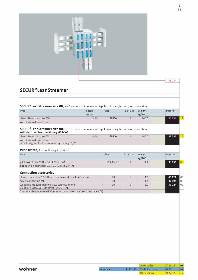
SECUR®LeanStreamer
SECUR®LeanStreamer size 00, NH fuse switch disconnector, 3-pole switching, bottom/top connectionType Rated Size Pack size Weight Part no.
current kg/100 u.clamp 70mm² / screw M8 160A NH00 1 146.0 33 234 12with terminal space cover
SECUR®LeanStreamer size 00, NH fuse switch disconnector, 3-pole switching, bottom/top connection, with electronic fuse monitoring, 400V ACclamp 70mm² / screw M8 160A NH00 1 146.0 33 285 12with terminal space cover circuit diagram for fuse monitoring on page 9/25
Pilot switch, for monitoring lid positionType Size Pack size Weight Part no.
kg/100 u.pilot switch: 250V AC / 5A; 30V DC / 4A 000, 00, 2, 3 1 1.1 33 156 09flat push-on connector 2.8 x 0.5 (DIN 46 244-A)
Connection accessoriesclamp connection 1.5 - 70mm2 for Cu cond., rm, f +AE; la. Cu 00 3 1.5 03 727 09screw connection M8 00 3 1.4 30 894 09wedge clamp terminal for screw connection M8, Cu and Al cond. 16-70mm² rm, sm, f, f +AE
* 00 3 3.0 33 224 09
* not maintenance-free if aluminium conductors are used (see page 8/2)
Accessories 7 13,14Approvals 8 57 - 66 Technical data 8 35
Dimensions 9 24,38
332
PHB2014_EN.indb 33 10.02.2014 15:46:23
33 40333 40233 42233 42131 95931 958
2/34
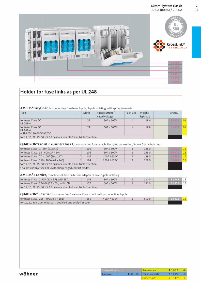
Holder for fuse links as per UL 248
AMBUS®EasyLiner, bus-mounting fuse base, 3-pole, 3-pole isolating, with spring terminalsType Width Rated current / Pack size Weight Part no.
Rated voltage kg/100 u.for fuses Class CC UL 248-4
27 30A / 600V 4 18.6 31 958 01
for fuses Class CC UL 248-4, with LED 110-600V AC/DC
27 30A / 600V 4 18.8 31 959 01
for 12, 15, 20, 25, 30 x 5, 10 busbars, double-T and triple-T section
QUADRON®CrossLinkCarrier Class J, bus-mounting fuse base, bottom/top connection, 3-pole, 3-pole isolatingfor fuses Class J 1 - 30A (21 x 57) 106 30A / 600V 1 138.0 33 421 16for fuses Class J 35 - 60A (27 x 60) 106 60A / 600V 1 135.0 33 422 16for fuses Class J 70 - 100A (29 x 117) * 106 100A / 600V 1 129.0 33 402 16for fuses Class J 110 - 200A (41 x 146) * 184 200A / 600V 1 278.0 33 403 16for 12, 15, 20, 25, 30 x 5, 10 busbars, double-T and triple-T section* do not use any fuse links with sharp-edged contact blades
AMBUS®J-Carrier, complete solution on busbar adapter, 3-pole, 3-pole isolatingfor fuses Class J 1-30A (21 x 57), with LED 108 30A / 600V 1 110.0 31 968 16for fuses Class J 35-60A (27 x 60), with LED 126 60A / 600V 1 131.0 31 970 16for 12, 15, 20, 25, 30 x 5, 10 busbars, double-T and triple-T section
QUADRON®J-Carrier, bus-mounting fuse base, Class J, bottom/top connection, 3-polefor fuses Class J 225 - 400A (54 x 181) 256 400A / 600V 1 690.0 33 311 16for 12, 20, 30 x 10mm busbars, double-T and triple-T section
Designation for UL Accessories 7 19-22Approvals 8 57 - 66 Technical data 8 17,25
Dimensions 9 16,17,18
3460mm-System classic 630A (800A) / 2500A
2
PHB2014_EN.indb 34 10.02.2014 15:46:27

31 96431 96332 14601 162
2/35
System components 4-pole
Busbar supportsType For busbars Pack size Weight Part no.
kg/100 u.IEC, 4-pole, with internal screw holes 12, 15, 20, 25, 30 x 5, 10 10 26.6 01 485 06UL, 4-pole, with internal screw holes 12, 20, 30 x 5, 10 10 19.7 01 357 06Spacer for 01 357 10 13.1 01 359 063-pole with internal screw holes double-T section 3 59.1 01 231 061-pole, for connection to 01 231 double-T section 4 13.0 01 116 063-pole with internal screw holes triple-T section 2 69.7 01 232 061-pole, for connection to 01 232 triple-T section 4 15.0 01 132 06
Connection set, 4-pole, for 20 x 5 - 30 x 10 and double-T and triple-T section, without cover capConnection Width For use Pack size Weight Part no.
up to max. kg/100 u.Cu and Al 120 - 300mm², rm, sm, f * 204 560A 1 210.0 01 147 07for flat busbars up to 32 x 20 204 800A 1 180.0 01 162 07* not maintenance-free if aluminium conductors are used (see page 8/2)
System cover, 4-poleType Pack size Weight Part no.
kg/100 u.holder set (left + right) for cover sections, 4-pole 1 21.0 01 137 07front cover section (4-pole), 1.1m long, only with holder 01 137 1 58.0 01 599 07top/bottom cover section, 1.1m long, only with holder 01 136 or 01 137 2 27.1 01 555 07can be used for systems with 12, 15, 20, 25, 30 x 5/10 busbars, double-T and triple-T section
Cover cap, 4-pole228 x 260 x 90 1 45.0 01 597 07
PE/N module, with 2 connection terminals 16mm2, without leadsType Width Height Pack size Weight Part no.
kg/100 u.can be connected on both sides, only for use withEQUES adapter
18 242 4 14.1 32 146 05
AMBUS®EasyLiner, bus-mounting fuse base, 3-pole + N, 4-pole isolating, with spring terminalsType Rated current / Pack size Weight Part no.
Rated voltage kg/100 u.for fuses 10 x 38 IEC 60 269-2 32A / 690V 4 25.2 31 963 01for fuses 10 x 38 IEC 60 269-2, with LED 110-690V AC/DC 32A / 690V 4 25.2 31 964 01
Designation for UL Accessories 7 15,17Approvals 8 57 - 66 Technical data 8 6-17
Dimensions 9 5-16
352
PHB2014_EN.indb 35 10.02.2014 15:46:32

32 58332 58032 578
2/36
EQUES®PowerConnector 4-pole
EQUES®PowerConnector, busbar adapter, 4-pole, phase division 35-36mm, top connectionType Rated Adapter Adapter SU Weight Part no.
current length width kg/100 u.for ABB Tmax T4 250A 270 140 1 180.0 32 584 05for Schneider Electric NSX100-NSX250 250A 270 140 1 180.0 32 582 05for Eaton NZM2-XKR4O 250A 270 140 1 180.0 32 580 05for Siemens 3VL2, 3VL3 250A 270 140 1 180.0 32 578 05top connection of switch to busbar system
EQUES®PowerConnector, busbar adapter, 4-pole, phase division 43-45mm, top connectionfor ABB Tmax T5 500A 300 185 1 360.0 32 585 05for Schneider Electric NS400/630, NSX 400/630
500A 300 185 1 350.0 32 583 05
for Eaton NZM3-XKR13O 500A 300 185 1 350.0 32 581 05for Siemens 3VL400 400A 300 185 1 350.0 32 579 05top connection of switch to busbar system
Designation for ULApprovals 8 57 - 66 Technical data 8 14
Dimensions 9 15
All adapters for busbars 12, 15, 20, 25, 30 x 5, 10, double-T and triple-T section.
3660mm-System classic 630A (800A) / 2500A
2
PHB2014_EN.indb 36 10.02.2014 15:46:35