Embed Size (px)
Citation preview

Foods are complex mixtures of compounds and the extraction or separation of foodcomponents is fundamental for the preparation of ingredients to be used in otherprocesses (for example cooking oils from oilseeds or gelatin from connective tissue); orfor retrieval of high value compounds, such as enzymes (e.g. papain from papaya formeat tenderisation or rennet from calf stomachs for cheesemaking). Other types ofseparation methods are used to sort foods by separating them into classes based on size,colour or shape; to clean them by separating contaminating materials (Chapter 3); or toselectively remove water from foods by evaporation (Chapter 13) or by dehydration(Chapter 15).
In this chapter, the unit operations that are used for the physical removal of foodcomponents by separation, extraction or concentration are described. There are threemain categories:
1. Separation of liquids and solids from slurries, pastes, particulates or flours, whereeither one or both components may be valuable (for example juices, pectin, enzymes,cooking oil, cream and coffee solubles).
2. Separation of small amounts (less than 2%) of solids from liquids. Here the mainpurpose is purification of water or clarification of liquids such as wine, beer, juices,etc. and the solids are not valuable.
3. Extraction of small amounts of valuable materials using a solvent.
Each operation is used as an aid to processing and is not intended to preserve food.Changes in nutritional and sensory qualities arise through intentional separation orconcentration of food components, but generally the processing conditions do not involveheat and cause little damage to foods. Other methods for separation of food componentsinclude sieving, described in Chapter 4, and crystallisation and distillation, described byBrennan et al. (1990) and Heldman and Hartel (1997b). Osmotic concentration of fruitsand vegetables, by soaking in concentrated solutions of sugar or salt respectively, is aform of dehydration and is discussed further in Chapter 15.
6
Separation and concentration of foodcomponents
6.1 Centrifugation
There are two main applications of centrifugation: separation of immiscible liquids andseparation of solids from liquids. Separation of solid particles from air by centrifugalaction in the ‘cyclone’ separator is described in more detail in Chapter 15 and byHeldman and Hartel (1997b).
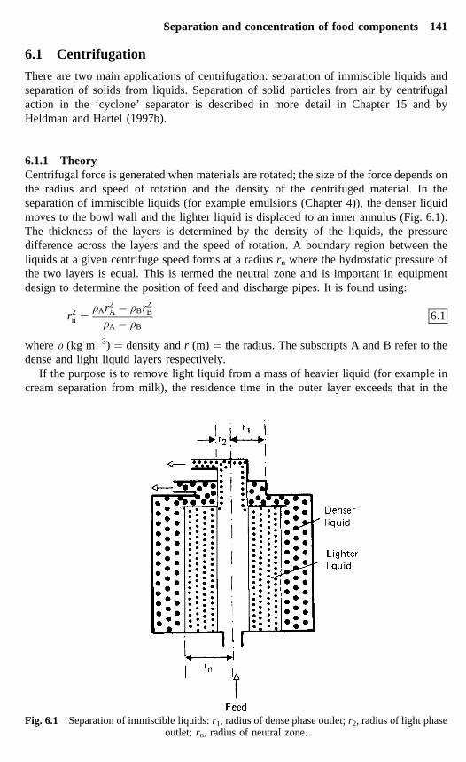
6.1.1 TheoryCentrifugal force is generated when materials are rotated; the size of the force depends onthe radius and speed of rotation and the density of the centrifuged material. In theseparation of immiscible liquids (for example emulsions (Chapter 4)), the denser liquidmoves to the bowl wall and the lighter liquid is displaced to an inner annulus (Fig. 6.1).The thickness of the layers is determined by the density of the liquids, the pressuredifference across the layers and the speed of rotation. A boundary region between theliquids at a given centrifuge speed forms at a radius rn where the hydrostatic pressure ofthe two layers is equal. This is termed the neutral zone and is important in equipmentdesign to determine the position of feed and discharge pipes. It is found using:
r2n � �Ar2
A � �Br2B
�A � �B6�1
where � (kg m�3) � density and r (m) � the radius. The subscripts A and B refer to thedense and light liquid layers respectively.
If the purpose is to remove light liquid from a mass of heavier liquid (for example incream separation from milk), the residence time in the outer layer exceeds that in the
Fig. 6.1 Separation of immiscible liquids: r1, radius of dense phase outlet; r2, radius of light phaseoutlet; rn, radius of neutral zone.
Separation and concentration of food components 141

inner layer. This is achieved by using a smaller radius of the outer layer (r1 in Fig. 6.1)and hence reducing the radius of the neutral zone. Conversely, if a dense liquid is to beseparated from a mass of lighter liquid (for example the removal of water from oils), theradius of the outer layer (and the neutral zone) is increased.
When particles are removed from liquids in centrifugal clarification, the particlesmove to the bowl wall under centrifugal force. If liquid flow is streamlined (Chapter 1),the rate of movement is determined by the densities of the particles and liquid, theviscosity of the liquid and the speed of rotation (equation 6.2). Separation under turbulentflow conditions is described by Earle (1983).
Q � D2�2��s � ��V18�ln�r2�r1� 6�2
where � �� 2�N /60) � angular velocity, Q (m3 s�1) � volumetric flowrate, V (m3) �operating volume of the centrifuge, D (m) � diameter of the particle, �s (kg m�3) �density of particles, � (kg m�3) � density of liquid, � (N s m�2) � viscosity of liquid, r2
(m) � radius of centrifuge bowl, r1 (m) � radius of liquid, N (rev s�1) � speed ofrotation.
For a given particle diameter, the average residence time of a suspension equals thetime taken for a particle to travel through the liquid to the centrifuge wall:
t � VQ
6�3
where t (s) � residence time. The flow rate can therefore be adjusted to retain a specificrange of particle sizes. Derivations and additional details of these equations are given byBrennan et al. (1990) and Earle (1983).
6.1.2 EquipmentCentrifuges are classified into three groups for:
1. separation of immiscible liquids2. clarification of liquids by removal of small amounts of solids (centrifugal clarifiers)
Sample problem 6.1A bowl centrifuge is used to break an oil-in-water emulsion (Chapter 4). Determinethe radius of the neutral zone in order to position the feed pipe correctly. (Assume thatthe density of the continuous phase is 1000 kg m�3 and the density of the oil is 870 kgm�3. The outlet radii from the centrifuge are 3 cm and 4.5 cm.)
Solution to Sample problem 6.1
rn ���
1000�0�045�2 � 870�0�03�2
1000 � 870
�
���
2�025 � 0�783130
�
� 0�097 m
142 Food processing technology

Sample problem 6.2Beer with a specific gravity of 1.042 and a viscosity of 1.40 �10�3 N s m�2 contains1.5% solids which have a density of 1160 kg m�3. It is clarified at the rate of 240 l h�1
in a bowl centrifuge which has an operating volume of 0.09 m3 and a speed of 10 000min�1. The bowl has a diameter of 5.5 cm and is fitted with a 4 cm outlet. Calculatethe effect on feed rate of an increase in bowl speed to 15 000 rev min�1 and theminimum rev particle size that can be removed at the higher speed.
Solution to Sample problem 6.2From equation (6.2),
Initial flow rate Q1 � D2�2�N1�60�2��s � ��V18�ln�rw�r�
New flow rate Q2 � D2�2�N2�60�2��s � ��V18�ln�rw�r�
As all conditions except the bowl speed remain the same,
Q2
Q1� �2�N2�60�2
�2�N1�60�2
Q2
240�3600� �2 � 3�142 � 15000�60�2
�2 � 3�142 � 10000�60�2
Therefore,
Q2 � 0�15 l s�1
� 540 l h�1
To find the minimum particle size from equation (6.2),
D2 � Q2 � Q2�18� ln�rw�r��w2��s � ��V
� Q2�18� ln�rw�r���2�N2�60�2��s � ��V
� 0�015�18 � 1�40 � 10�3 � ln�0�0275�0�02��2 � 3�142 � �15000�60�2�1160 � 1042�0�09
D ���
2�33 � 10�4
2�62 � 107
�
� 6�8�m
Separation and concentration of food components 143

3. removal of solids (desludging or dewatering centrifuges).
Specific applications of centrifuges are described by Hemfort (1984) for the fermentationindustries (Chapter 7) and by Hemfort (1983) for the food industry.
Liquid–liquid centrifugesThe simplest type of equipment is the tubular bowl centrifuge. It consists of a verticalcylinder (or bowl), typically 0.1 m in diameter and 0.75 m long, which rotates inside astationary casing at between 15 000 rev min�1 and 50 000 rev min�1 depending on thediameter. Feed liquor is introduced continuously at the base of the bowl and the twoliquids are separated and discharged through a circular weir system into stationary outlets(Fig. 6.1).
Better separation is obtained by the thinner layers of liquid formed in the disc bowlcentrifuge (Fig. 6.2). Here a cylindrical bowl, 0.2–1.2 m in diameter, contains a stack ofinverted metal cones which have a fixed clearance of 0.5–1.27 mm and rotate at 2000–7000 rev min�1. They have matching holes which form flow channels for liquidmovement. Feed is introduced at the base of the disc stack and the denser fraction movestowards the wall of the bowl, along the underside of the discs. The lighter fraction is
Fig. 6.2 Disc bowl centrifuge.(Adapted from Hemfort (1983).)
144 Food processing technology

displaced towards the centre along the upper surfaces and both liquid streams areremoved continuously by a weir system at the top of the centrifuge in a similar way to thetubular bowl system. Disc bowl centrifuges are used to separate cream from milk and toclarify oils, coffee extracts and juices (Table 6.1). Disc bowl and tubular centrifuges havecapacities of up to 150 000 l h�1.
Centrifugal clarifiersThe simplest solid–liquid centrifuge is a solid bowl clarifier, which is a rotatingcylindrical bowl, 0.6–1.0 m in diameter. Liquor, with a maximum of 3% w/w solids, isfed into the bowl and the solids form a cake on the bowl wall. When this has reached apre-determined thickness, the bowl is drained and the cake is removed automaticallythrough an opening in the base. Feeds which contain a higher solids content (Table 6.1)are separated using nozzle centrifuges or valve discharge centrifuges. These are similar todisc bowl types, but the bowls have a biconical shape. In the nozzle type, solids arecontinuously discharged through small holes at the periphery of the bowl and arecollected in a containing vessel. In the valve type the holes are fitted with valves thatperiodically open for a fraction of a second to discharge the accumulated solids. Theadvantages of the latter design include less wastage of liquor and the production of driersolids. Both types are able to separate feed liquor into three streams: a light phase, adense phase and solids. Centrifugal clarifiers are used to treat oils, juices, beer andstarches and to recover yeast cells. They have capacities up to 300 000 l h�1.
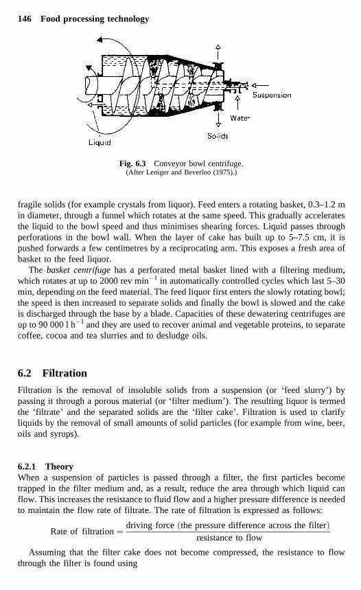
Desludging, decanting or dewatering centrifugesFeeds with high solids contents (Table 6.1) are separated using desludging centrifuges,including conveyor bowl, screen conveyor, basket and reciprocating conveyorcentrifuges. In the conveyor bowl centrifuge the solid bowl rotates up to 25 rev min�1
faster than the screw conveyor (Fig. 6.3). This causes the solids to be conveyed to oneend of the centrifuge, whereas the liquid fraction moves to the other larger-diameter end.The solids are relatively dry compared with other types of equipment.
The screen conveyor centrifuge has a similar design but the bowl is perforated toremove the liquid fraction. The reciprocating conveyor centrifuge is used to separate
Table 6.1 Applications of centrifuges in food processing
Rangeof Solidsparticle content Applications
Centrifuge sizes of feedtype (�m) (% of w/w) A B C D E F G H
Disc bowlClarifier 0.5–500 �5 ★ ★ ★Self-cleaning 0.5–500 2–10 ★ ★ ★ ★ ★ ★
Nozzle bowl 0.5–500 5–25 ★ ★ ★ ★ ★ ★Decanter 5–50 000 3–60 ★ ★ ★ ★ ★ ★ ★Basket 7.5–10 000 5–60 ★ ★Reciprocating 100–80 000 20–75 ★ ★conveyor
A, liquid–liquid extraction; B, separation of liquid mixtures; C, clarification of liquids; D, concentration ofslurries; E, liquid–solid–liquid extraction; F, dehydration of amorphous materials; G, de-watering of crystallinefoods; H, wet classification.Adapted from Hemfort (1983).
Separation and concentration of food components 145
fragile solids (for example crystals from liquor). Feed enters a rotating basket, 0.3–1.2 min diameter, through a funnel which rotates at the same speed. This gradually acceleratesthe liquid to the bowl speed and thus minimises shearing forces. Liquid passes throughperforations in the bowl wall. When the layer of cake has built up to 5–7.5 cm, it ispushed forwards a few centimetres by a reciprocating arm. This exposes a fresh area ofbasket to the feed liquor.
The basket centrifuge has a perforated metal basket lined with a filtering medium,which rotates at up to 2000 rev min�1 in automatically controlled cycles which last 5–30min, depending on the feed material. The feed liquor first enters the slowly rotating bowl;the speed is then increased to separate solids and finally the bowl is slowed and the cakeis discharged through the base by a blade. Capacities of these dewatering centrifuges areup to 90 000 l h�1 and they are used to recover animal and vegetable proteins, to separatecoffee, cocoa and tea slurries and to desludge oils.
6.2 Filtration
Filtration is the removal of insoluble solids from a suspension (or ‘feed slurry’) bypassing it through a porous material (or ‘filter medium’). The resulting liquor is termedthe ‘filtrate’ and the separated solids are the ‘filter cake’. Filtration is used to clarifyliquids by the removal of small amounts of solid particles (for example from wine, beer,oils and syrups).
6.2.1 TheoryWhen a suspension of particles is passed through a filter, the first particles becometrapped in the filter medium and, as a result, reduce the area through which liquid canflow. This increases the resistance to fluid flow and a higher pressure difference is neededto maintain the flow rate of filtrate. The rate of filtration is expressed as follows:
Rate of filtration � driving force �the pressure difference across the filter�resistance to flow
Assuming that the filter cake does not become compressed, the resistance to flowthrough the filter is found using
Fig. 6.3 Conveyor bowl centrifuge.(After Leniger and Beverloo (1975).)
146 Food processing technology

R � �r
�VcV
A � L
�6�4
where R (m�2) � resistance to flow through the filter, � (N s m�2) � viscosity of theliquid, r (m�2) � specific resistance of the filter cake, V (m3) � volume of the filtrate, Vc
� the fractional volume of filter cake in the feed liquid volume, V, A (m2) � area of thefilter and L � equivalent thickness of the filter and initial cake layer.
For constant rate filtration, the flow rate through the filter is found using:
Q � �rVVc
A2�P� �rL
A�P6�5
where Q (V/t) (m3 s�1) � flow rate of filtrate, �P (Pa) � pressure difference and t (s) �filtration time. This equation is used to calculate the pressure drop required to achieve adesired flow rate or to predict the performance of large scale filters on the basis of datafrom pilot scale studies.
In constant-pressure filtration, the flow rate gradually decreases as the resistance toflow, caused by the accumulating cake, increases. Equation (6.5) is rewritten with �Pconstant as:
tAV
� �rVc
2�PVA� �rL
�P6�6
If t��V�A� is plotted against V�A, a straight line is obtained (Fig. 6.4). The slope(equation 6.7) and the intercept (equation 6.8) are used to find the specific resistance ofthe cake and the equivalent cake thickness of the filter medium:
Slope � �rVc�2�P 6�7
Intercept � �rL��P 6�8
If the filter cake is compressible (that is the specific resistance changes with appliedpressure) the term r is modified as follows:
r � r��P�s 6�9
Fig. 6.4 Graph of t��V�A� versus V/A.
Separation and concentration of food components 147

where r is the specific resistance of the cake under a pressure difference of 101 � 103 Paand s � the compressibility of the cake. This is then used in equation (6.4). Derivations ofthe above equations and further details are given by Earle (1983), Jackson and Lamb(1981) and Toledo (1999a).
Sample problem 6.3Pulp which contains 15% solids is filtered in a plate and frame fitter press (Section6.2.2) with a pressure difference of 290 Pa. The masses of filtrate are shown below fora 1.5 h cycle. Calculate the specific resistance of the cake and the volume of filtratethat would be obtained if the cycle time were reduced to 45 min. (Assume that thecake is incompressible and the viscosity of the filtrate is 1.33 � 10�3 N s m�2.)
Time (min) 7.5 30.4 50 90Mass of filtrate (kg) 1800 3800 4900 6800
Solution to Sample problem 6.3Time (s): 450 1825 3000 5400V (m3) 1.8 3.8 4.9 6.8V/A 0.33 0.69 0.89 1.24t/(V/A) 1364 2645 3371 4355
Plotting t/(V/A) vs (V/A) (Fig. 6.4)
slope � 2666�7
intercept � 300
(1) From equation (6.7)
2666�7 � 1�33 � 10�3 � r � 0�15�2 � 290
r � 92273 m�2
(2) From equation (6.6)
tA�V � 2666�7 �V�A� � 300
For a 45 min (2700 s) cycle
2700 � 2666�7�V�0�55�2 � 300�V�0�55�
V0�55
� �300 ��90000 � 10800 � 2666�7�
2 � 2666�7� 0�52 m3
148 Food processing technology

6.2.2 EquipmentGravity filtration is slow and finds little application in the food industry. Filtrationequipment operates either by the application of pressure to the feed side of the filter bedor by the application of a partial vacuum to the opposite side of the filter bed. Centrifugalfiltration using a basket centrifuge is described above. Filter aids are usually applied tothe filter or mixed with the food to improve the formation of filter cake.
Pressure filtersTwo commonly used pressure filters are the batch plate-and-frame filter press (Fig. 6.5)and the shell-and-leaf pressure filter. In the plate-and-frame design, cloth or paper filtersare supported on vertical plates. Feed liquor is pumped into the press and liquid passesthrough the filter cloths and flows down the grooved surfaces of the plates to drainthrough an outlet channel in the base of each plate. A layer of cake builds up on the clothsuntil the space between the plates is filled.
In operation, the pressure is increased to a pre-determined value and the plates are thenback-washed with water. The press is dismantled and the cake is removed, ready to beginanother cycle. The filter press has relatively low capital costs, high flexibility fordifferent foods, it is reliable and easily maintained. It is widely used for the production ofapple juice and cider (for example Jones et al., 1983). However, it is time consuming andhighly labour intensive.
The shell-and-leaf pressure filter is used to overcome the problems of high labourcosts and lack of convenience of plate-and-frame presses. It consists of mesh ‘leaves’,which are coated in filter medium and supported on a hollow frame which forms theoutlet channel for the filtrate. The leaves are stacked horizontally or vertically inside apressure vessel, and in some designs they rotate at 1–2 rev min�1 to improve theuniformity of cake buildup. Feed liquor is pumped into the shell at a pressure ofapproximately 400 � 103 Pa. When filtration is completed, the cake is blown or washedfrom the leaves. This equipment has a higher cost than plate filters and is best suited toroutine filtration of liquors which have similar characteristics.
Vacuum filtersVacuum filters are limited by the cost of vacuum generation to a pressure difference ofabout 100 �103 Pa. However, cake is removed at atmospheric pressure and these types of
Fig. 6.5 Plate-and-frame filter press.
Separation and concentration of food components 149

filter are therefore able to operate continuously. (Pressure filters have batch operationbecause the pressure must be reduced for cake removal.) Two common types of vacuumfilter are the rotary drum filter and rotary disc filter.
A rotary drum filter consists of a horizontal cylinder which has the surface dividedinto a series of shallow compartments, each covered in filter cloth and connected to acentral vacuum pump (Fig. 6.6). As the drum rotates, it dips into a bath of liquor andfiltrate flows through the filter and out through channels in the drum. When acompartment leaves the bath, the filter cake is sucked free of liquor, washed with spraysand the vacuum is released. Compressed air is blown from beneath the cloth to loosen thecake, which is removed by a scraper before the individual compartment restarts the cycle.
Rotary vacuum disc filters consist of a series of vertical discs which rotate slowly in abath of liquor in a similar cycle to drum filters. Each disc is divided into portions whichhave outlets to a central shaft. The discs are fitted with scrapers to remove the cakecontinuously. These types of filter are compact and have low labour costs and highcapacity. However, they have high capital costs and produce cake which has a moderatelyhigh moisture content.
6.3 Expression
6.3.1 TheoryThe main applications of expression are in the extraction of components plant materialseither for direct consumption (for example fruit juices) or for use in subsequentprocessing (for example sugar, grape juice for wine and vegetable oils). These materialsare located within the cell structure of the plants and it is necessary to disrupt the cells inorder to release them. This is achieved either in a single-stage, which both ruptures thecells and expresses the liquid, or in two stages (size reduction to produce a pulp or flour,followed by separation in a press). In general the single-stage operation is moreeconomical, permits higher throughputs and has lower capital and operating costs, but forsome products that are especially hard (for example oil bearing nuts) a two-stageexpression is more effective. Better extraction is achieved by heating oilseeds or flours toreduce the oil viscosity, release oil from intact cells and remove moisture. There is anoptimum moisture content for each type of oil seed to obtain a maximum yield of oil.
Fig. 6.6 Rotary drum filter.(After Leniger and Beverloo (1975).)
150 Food processing technology

In fruit processing, the press should remove the maximum quantity of juice, withoutsubstantial quantities of solids, or phenolic compounds from the skins which causebitterness and browning. This is achieved using lower pressures and fewer pressings. It isalso necessary to increase the pressure slowly to avoid the formation of a denseimpenetrable press cake, as the solid material is easily deformed and blocks the press.
The factors that influence the juice yield from a press include:
• maturity and growth conditions of the raw material• extent of cell disruption• thickness of the pressed solids and their resistance to deformation• rate of increase in pressure, the time of pressing and the maximum pressure applied• temperatures of solids and liquid and the viscosity of the expressed liquid.
6.3.2 EquipmentBatch pressesCommon types of equipment for expressing juice or oils are the tank press and the cagepress.
The tank press is used for fruit juice production and consists of a horizontal cylinderwhich is divided internally by a membrane. During an automatically controlled pressingcycle of 1.5 h, fruit pulp is fed into one side of the membrane and compressed air isapplied to the opposite side (Fig. 6.7). Juice flows out through channels and, whenpressing is completed, the tank is rotated to loosen and discharge the press residue. Highyields of good-quality juice are obtained by the gentle increase in pressure at capacitiesranging from 3600 kg to 25 000 kg (Vine, 1987).
In the cage press, up to 2 t of fruit pulp or oilseed flour is placed into a verticalperforated or slatted cage, either loose or in cloth bags depending on the nature of thematerial. In larger presses, ribbed layer plates are used to reduce the thickness of the pulpor flour bed. The pressure is gradually increased on the top plate by an hydraulic systemor motor-driven screw thread and liquid is collected at the base of the press. Theequipment allows close control over the pressure exerted on the pulp/flour and mayoperate semi-automatically to reduce labour costs.
Fig. 6.7 Tank press: 1, tank filled; 2, membrane partly inflated; 3, membrane further inflated;4, loosening residue; 5, discharge.
(After Vine (1987).)
Separation and concentration of food components 151

Continuous pressesThere are several types of continuous press used commercially: the belt press for fruitprocessing, the screw expeller for both fruit processing and oil extraction (a similardesign is used for extrusion (Chapter 14)), and the roller press for sugar cane processing.
Belt presses consist of a continuous belt, made from canvas-plastic compositematerial, which passes under tension over two hollow stainless steel cylinders, one ofwhich is perforated. Pulped fruit is fed onto the inside of the belt and is pressed betweenthe belt and the perforated cylinder. Juice flows through the perforations and the presscake continues around the belt and is removed by a scraper or auger. They produce highyields of good-quality juice but have high capital costs and difficulty in maintenance andcleaning.
The screw expeller consists of a robust horizontal barrel containing a stainless steelhelical screw (Fig. 6.8). The pitch of the screw flights gradually decreases towards thedischarge end, to increase the pressure on the material as it is carried through the barrel.The final section of the barrel is perforated to allow expressed liquid to escape. Press cakeis discharged through the barrel outlet and the pressure in the barrel is regulated byadjusting the diameter of the discharge port. Frictional heat reduces the viscosity of theoil and some types of expellers have supplementary heaters fitted to the barrel to improveyields. In juice extraction the barrel is cooled to reduce the friction heat, generated by themovement of food, which may have an undesirable effect on flavour and aroma.Capacities range from 40 kg h�1 to 8000 kg h�1. The oil cake has 5–18% (w/w) residualoil, depending on the type of oil-seed and the operating conditions (Barker, 1987). Amodified screw press is described by Stein (1984), (Fig. 6.8), in which high shearingforces act on the seeds as they are forced through a series of throttle rings located in thebarrel.
In the roller press, pulp or sugar cane is fed between heavy fluted metal rollers andliquid flows along the grooves to a collection pan.
Fig. 6.8 Screw press, showing throttle ring used for oilseed pressing.(After Brennan et al. (1990) and Stein (1984).)
152 Food processing technology
6.4 Extraction using solvents
Unit operations that involve separation of specific components of foods are important in anumber of applications, including production of:
• cooking oils or speciality oils from nuts and seeds• flavours and essential oils (e.g. black pepper, cardamom, clove, ginger, hops, parsley,
vanilla, etc.)• coffee• sugar• removal of caffeine from coffee and tea.
Once the solvent has been removed from the extracted foods, some may be useddirectly (for example cooking oils) or they may be further processed by concentration(Section 6.5 and Chapter 13) and/or dehydration (Chapter 15). Many extractionoperations operate close to ambient temperature, but even when elevated temperaturesare used to increase the rate of extraction, there is little damage caused by heat and theproduct quality is not significantly affected.
The main types of solvents used for extraction are water, organic solvents orsupercritical carbon dioxide. These are described below.
6.4.1 TheorySolid-liquid extraction involves the removal of a desired component (the solute) from afood using a liquid (the solvent) which is able to dissolve the solute. This involves mixingthe food and solvent together, either in a single stage or in multiple stages, holding for apre-determined time and then separating the solvent. During the holding period there ismass transfer of solutes from the food material to the solvent, which occurs in threestages:
1. the solute dissolves in the solvent2. the solution moves through the particle of food to its surface3. the solution becomes dispersed in the bulk of the solvent.
During extraction, the holding time should therefore be sufficient for the solvent todissolve sufficient solute and for the changes in composition to approach an equilibrium.The time required depends on the solubility of a given solute in the solvent selected andalso on the following factors:
• The temperature of extraction. Higher temperatures increase both the rate at whichsolutes dissolve in the solvent and the rate of diffusion into the bulk of the solvent. Thetemperature of most extraction operations is limited to less than 100ºC by economicconsiderations, extraction of undesirable components at higher temperatures or heatdamage to food components.
• The surface area of solids exposed to the solvent. The rate of mass transfer is directlyproportional to the surface area, so reductions in particle size (giving an increase insurface area) increase the rate of extraction up to certain limits.
• The viscosity of the solvent. This should be sufficiently low to enable the solvent topenetrate easily the bed of solid particles.
• The flowrate of the solvent. Higher flowrates reduce the boundary layer ofconcentrated solute at the surface of particles and thus increase the rate of extraction.
Separation and concentration of food components 153

Examples of mass transfer are described in Chapter 1 and further details are given inBrennan et al. (1990) and Toledo (1999b).
SolventsThe types of solvent used commercially to extract food components are shown in Table6.2. Extraction using water (leaching) has obvious advantages of low cost and safety andis used to extract sugar, coffee and tea. Oils and fats require an organic solvent and asthese are highly flammable, great care is needed in both operating procedures and toensure that equipment is gas-tight and electrical apparatus is spark-proof.
Supercritical carbon dioxide has found increasingly widespread application forremoving caffeine from coffee or tea and for producing hop extracts for brewing(Gardner, 1982). It has also been used to extract and concentrate flavour compounds fromfruits and spices (including pepper, marjoram, nutmeg, cardamom, cloves and ginger),and speciality oils from citrus and a variety of nuts and seeds. The combination ofsupercritical CO2 and extrusion to produce a new range of breakfast cereals, pastaproducts and confectionery is described by Rizvi et al. (1995). Gaehrs (1990) hasreviewed the economics of extraction and applications to different products and the topicis comprehensively reviewed by Steytler (1996).
The term supercritical arises from the critical temperature and critical pressure lines ona pressure–temperature diagram (Fig. 6.9). The supercritical region for carbon dioxide iswhen it is above the critical pressure line and to the right of the critical temperature line(31ºC) (Brogle, 1982). As a solvent it acts as a liquid but has a low viscosity and diffuseseasily like a gas. It has the advantages of being highly volatile and so is easily separatedfrom solute without leaving any residues in the food. It is also non-flammable, non-toxic,bacteriostatic and low cost. It is used under conditions that are close to the critical point(near-critical fluid or NCF) for de-odourising applications or for highly soluble solutes.For more complete extraction or for applications that involve less soluble solutes, it isused at higher temperatures and pressures (Rizvi et al., 1986). The upper limit for theoperating temperature is the heat sensitivity of the food components and the upper limitfor pressure (about 40 MPa) is the cost of pressurised equipment.
Table 6.2 Solvents used to extract food components
Food Solvent Final soluteconcentration (%)
Temperature (ºC)
Decaffeinated coffee Supercritical carbondioxide, water ormethylene chloride
N/A 30–50 (CO2)
Fish livers, meatbyproducts
Acetone or ethyl ether N/A 30–50
Hop extract Supercritical carbondioxide
N/A �100–180
Instant coffee Water 25–30 70–90Instant tea Water 2.5–5 N/AOlive oil Carbon disulphide N/ASeed, bean and nut oils(e.g. from soybeans,groundnuts, cottonseed,sunflower seed, etc.)
Hexane, heptane orcyclohexane
N/A 63–70 (hexane)90–99 (heptane)71–85 (cyclohexane)
Sugar beet Water approx. 15 55–85
Adapted from data of Brennan et al. (1990) and Clarke (1990).
154 Food processing technology

6.4.2 EquipmentExtractors are either single-stage or multi-stage static tanks or continuous extractors. Thecomponents of a typical extraction unit that uses near-critical CO2 solvent are shown inFig. 6.10.
The essential components are an extraction vessel, a separation vessel, a condenserand a pump. In supercritical CO2 extraction, CO2 is stored as a near-critical liquid in thecondenser and then pumped to the extraction vessel through a heat exchanger by a highpressure pump. The state of the CO2 in the extractor is determined by the pressure,controlled by pressure relief valve, and the temperature, thermostatically controlled byliquid recirculating through a jacket surrounding the vessel. The material to be extractedis purged with gaseous CO2 to remove air and then liquid CO2 is pumped in at a rate thatpermits a sufficient residence time for equilibrium conditions to be established. Thesolution is then passed to the separation vessel in which conditions are adjusted tominimise the solubility of the extracted components (often by decompression). The CO2
is then returned to the cooled condenser for re-use and the extract is removed from theseparation vessel.
Single-stage extractorsThese are closed tanks, fitted with a mesh base to support the solid particles of food.Heated solvent percolates down through the particles and is collected below the mesh
Fig. 6.9 Pressure–temperature diagram for carbon dioxide. TP � triple point, CP � critical point,Tc � critical temperature (31.06ºC), Pc � critical pressure (73.8 bar).
(Adapted from Brennan et al. (1990).)
Separation and concentration of food components 155

base, with or without recirculation. They are used to extract oils or to produce coffee ortea extracts. Instant coffee production is described in detail by Clarke (1990). Althoughthey have low capital and operating costs, single-stage extractors produce relativelydilute solutions which may require expensive solvent recovery systems for organicsolvents or pollution control measures when water is used as the solvent.
Multi-stage extractorsThese comprise a series of up to 15 tanks, each similar to single extractors, linkedtogether so that solvent emerging from the base of one extractor is pumped counter-currently to the next in the series. These are used to produce oils, tea and coffee extractsand to extract sugar from beet.
Continuous extractorsThere are a large number of designs of extractor, each of which may operate counter-currently and/or co-currently. For example, one design is an enclosed tank containing twovertical bucket elevators (Chapter 26) made from perforated buckets and linked to form acontinuous ring. Fresh material is loaded into the descending buckets of one elevator andsolvent is pumped in at the top to extract solutes co-currently. As the buckets then moveupwards, fresh solvent is introduced at the top of the second elevator to extract solutescounter-currently. The solution collects at the base and is pumped to the top of the firstelevator to extract more solute, or it is separated for further processing. Other designs ofequipment employ perforated screw conveyors instead of bucket elevators.
Fig. 6.10 Layout of a CO2 extraction plant.(Adapted from Steytler (1996).)
156 Food processing technology

Other designs use a rotating carousel in which segments with perforated bases contain thefeed material. Solvent is sprayed onto each segment, collected at the base and pumped to thepreceding segment to produce counter-current extraction. These and centrifugal separators(Section 6.1.2) are used to extract oils, coffee, sugar beet, and in the preparation of proteinisolates. Further details of their operation are given by Brennan et al. (1990).
6.5 Membrane concentration (hyperfiltration and ultrafiltration)
Reverse osmosis (RO) (or ‘hyperfiltration’) and ultrafiltration (UF) are both unitoperations in which water and some solutes in a solution are selectively removed througha semi-permeable membrane. They are similar in that the driving force for transportacross the membrane is the pressure applied to the feed liquid. However, reverse osmosisis used to separate water from low-molecular-weight solutes (for example salts,monosaccharides and aroma compounds), which have a high osmotic pressure (Table6.3). A high pressure, five to ten times that used in UF (4000–8000 �103 Pa), is thereforenecessary to overcome this (hence the term reverse osmosis).
The largest commercial food application of reverse osmosis is the concentration ofwhey from cheese manufacture, either as a pre-concentration stage prior to drying or foruse in the manufacture of ice cream. Reverse osmosis is also used to:
• concentrate and purify fruit juices (Robe, 1983), enzymes, fermentation liquors andvegetable oils
• to concentrate wheat starch, citric acid, egg white, milk, coffee, syrups, naturalextracts and flavours
• to clarify wine and beer• to demineralise and purify water from boreholes or rivers or by desalination of sea water.
In the last application, monovalent and polyvalent ions, particles, bacteria and organicmaterials with a molecular weight greater than 300 are all removed by up to 99.9% togive high-purity process water for beverage manufacture and other applications.
Other applications include ‘dealcoholisation’ to produce low-alcohol beers, cider andwines, and recovery of proteins or other solids from distillation residues, dilute juices,waste water from corn milling or other process washwaters. Membrane pre-concentrationis also used to prepare coffee extracts and liquid egg for drying and to pre-concentrate
Table 6.3 Osmotic pressures of selected solutions
Solution Concentration Osmotic pressure (Pa � 105)
Apple juice 15º Brix 2.04Citrus juice 10º Brix 1.48Coffee extract 28% TS 3.40Lactose 1% w/v 0.37Milk – 0.69Salt solution 15% TS 13.8Sucrose solution 44º Brix 6.9Sugar syrup 20º Brix 3.41Tomato paste 33º Brix 6.9Whey – 0.69
TS = total solids, w/v = weight per volume.Adapted from Lewis (1996a).
Separation and concentration of food components 157

juices and dairy products before evaporation, so improving the economy of evaporators.Concentrating fluids by removal of water at low temperatures in the dairy, fruit juice andsugar processing industries competes with vacuum evaporation (Chapter 13) and freezeconcentration (Chapter 22). The advantages of membrane concentration over concentra-tion by evaporation are:
• the food is not heated, and there is therefore negligible loss of volatiles or changes tonutritional or eating quality
• in contrast with boiling, membrane concentration does not involve a change in phaseand therefore uses energy more efficiently (Table 6.4)
• simple installation with lower labour and operating costs• no requirement for steam boilers.
The main limitations of membrane concentration are:
• variation in the product flow rate when changes occur in the concentration of feedliquor
• higher capital costs than evaporation• a maximum concentration to 30% total solids• fouling of the membranes (deposition of polymers), which reduces the operating time
between membrane cleaning.
Different types of membrane reject solutes with specific ranges of molecular weight(Fig. 6.11). These molecular weight ‘cutoff’ points are used to characterise membranes.For reverse osmosis membranes, the cutoff points range from molecular weights of 100Da at 4000–7000 � 103 Pa to 500 Da at 2500–4000 � 103 Pa.
Table 6.4 Comparison of reverse osmosis and evaporation of whey
Parameter Reverse osmosis Evaporation
Steam consumption 0 250–550 kg per 1000 l waterremoved
Electricity consumption 10 kW h per 1000 l waterremoved (continuous); 20 kWh per 1000 l water removed(batch)
Approximately 5 kW h per 1000l water removed
Energy use (kW h) 3.6 (6–12% solids)8.8 (6–18% solids)9.6 (6–20% solids)
One effect 387 (6–50% solids)Two effects 90 (6–50% solids)Seven effects 60 (6–50% solids)MVR* 44
Labour 4 h day�1 Normally two operators duringwhole operation (boiler houseand evaporator)
Cooling-water consumption 0–29 300 kJ per 1000 l waterremoved (continuous);0–58 600 kJ per 1000 l waterremoved (batch)
(5.2–1.2) � 106 kJ per 1000 lwater removed
Economical plant size 6000 l day�1 day or more, noupper limit
80 000–100 000 l day�1
Consideration in final product Maximum 30% total solids.Capacity varies withconcentration
Up to 60% total solids
* MVR, mechanical vapour recompression.Adapted from Madsen (1974).
158 Food processing technology

The term nanofiltration (NF) (or ‘loose reverse osmosis’) is used when membranesremove materials having molecular weights in the order of 300–1000 Da (Rosenberg,1995). This compares to a molecular weight range of 2000–300 000 for ultrafiltrationmembranes, although above 30 000 there is overlap with microfiltration (Fig. 6.11). NF iscapable of removing ions that contribute significantly to the osmotic pressure and thusallows operation at pressures that are lower than those needed for RO.
UF membranes have a higher porosity and retain only large molecules (for exampleproteins or colloids) which have a lower osmotic pressure. Smaller solutes are transportedacross the membrane with the water. Ultrafiltration therefore operates at lower pressures(50–1000 � 103 Pa). The most common commercial application of ultrafiltration is in thedairy industry to concentrate milk prior to the manufacture of dairy products, toconcentrate whey to 20% solids or selectively to remove lactose and salts. In cheesemanufacture, ultrafiltration has advantages in producing a higher product yield andnutritional value, simpler standardisation of the solids content, lower rennet consumptionand easier processing. Other applications include:
• concentration of sucrose and tomato paste• treatment of still effluents in the brewing and distilling industries• separation and concentration of enzymes, other proteins or pectin• removal of protein hazes from honey and syrups• treatment of process water to remove bacteria and contaminants (greater than 0.003
�m in diameter) (Mackintosh, 1983)
Fig. 6.11 Size separation capabilities of different membrane systems.(From Anon. (1997).)
Separation and concentration of food components 159

• pre-treatment for reverse osmosis membranes to prevent fouling by suspended organicmaterials and colloidal materials.
An extension of UF, in which water is added back to the extract during theconcentration process is known as diafiltration. This is useful in selectively removinglower molecular weight materials from a mixture, and is described in detail by Lewis(1996b). It offers a useful alternative process to ion exchange or electrodialysis (seebelow) for removal of anions, cations, sugars, alcohol or antinutritional compounds.
Microfiltration (MF) is similar to UF in using lower pressures than RO, but isdistinguished by the larger range of particle sizes that are separated (0.01–2 �m) (Fig.6.11). Whereas UF is used to separate macromolecules, MF separates dispersed particlessuch as colloids, fat globules or cells, and may therefore be thought of as falling betweenUF and conventional filtration (Grandison and Finnigan, 1996). It was developed beforeother membrane processes but has advanced more slowly due to difficulties inmicroporous membrane design which trapped particles and blocked the material. Morerecent developments in membrane materials have partially overcome this problem topermit continuous processing of larger volumes of liquids with higher concentrations ofsuspended solids. An example of the applications of UF, MF and DF for the fractionationof milk proteins is shown in Fig. 6.12. These processes enable new possibilities to tailorthe functional properties of milk proteins (e.g. water holding capacity, fat binding,emulsification characteristics, whippability and heat stability) for specific applications asfood ingredients (Rosenberg, 1995).
Ion-exchange and electrodialysis are both separation methods that remove electricallycharged ions and molecules from liquids. In ion-exchange, solutes such as metal ions,proteins, amino acids and sugars are transferred from a feed material and retained on asolid ion-exchange material by a process of electrostatic adsorption (i.e. attractionbetween the charge on the solute and an opposite charge on the ion-exchanger). They canthen be separated by washing off the ion-exchanger. The ion-exchanger is either a cationexchanger (having a fixed negative charge) or an anion exchanger (having a fixedpositive charge). They are constructed using a porous matrix made from polyacrylamides,polystyrene, dextrans or silica. The applications in food processing include decolourisa-tion of sugar syrups, protein recovery from whey or blood, water softening anddimineralisation and separation of valuable materials such as purified enzymes(Grandison, 1996).
Electrodialysis (ED) is used to separate electrolytes from non-electrolytes and toexchange ions between solutions. A direct current is passed through a solution and ions ormolecules migrate due to their electrical charge towards an anode or a cathode.Separation is based on ion-selective membranes (sheets of cation- and anion-exchangematerials) which act as barriers to either anions or cations. Therefore anions that migratetowards the anode pass through anion membranes but are rejected by cation membranesand vice versa. The membranes are arranged alternately to form ion-diluting cells andion-concentrating cells. In an example described by Grandison (1996), cheese whey iscirculated through ion-diluting cells and brine is circulated through ion-concentratingcells. Mineral ions leave the whey and become concentrated in the brine, thusdemineralising the whey. This is a major application of ED and demineralised whey isused in infant feeds, drinks, salad dressing, confectionery coatings, ice cream mixes andbakery. It can also be used to remove potassium and tartaric acid from wines to preventprecipitate formation, to desalinate pickling brines and to de-acidify fruit juices to reducetheir sourness products (Grandison, 1996).
160 Food processing technology

Pervaporation is an emerging membrane separation technique, in which a liquid feedmixture is separated by partial vaporisation through a non-porous, selectively permeablemembrane. It produces a vapour permeate and a liquid retentate. Partial vaporisation isachieved by reducing the pressure on the permeate side of the membrane (vacuumpervaporation) or less commonly, sweeping an inert gas over the permeate side (sweepgas pervaporation). There are two types of membrane, which are used in two distinctapplications: hydrophilic polymers (e.g. poly (vinyl alcohol) or cellulose acetate)preferentially permit water permeation, whereas hydrophobic polymers (e.g. poly(dimethylsiloxane) or poly (trimethylsilylpropyne)) preferentially permit permeation oforganic materials. Vacuum pervaporation at ambient temperatures using hydrophilicmembranes is used to dealcoholise wines and beers, whereas hydrophobic membranes areused to concentrate aroma compounds, such as alcohols, aldehydes and esters, to up to
Fig. 6.12 Fractionation of milk proteins using UF, MF and DF. (EH � enzyme hydrolysis,T � temperature.)
(From Rosenberg (1995).)
Separation and concentration of food components 161

one hundred times the concentration in the feed material. The concentrate is then addedback to a food after processing (e.g. after evaporation, Chapter 13) to improve its sensorycharacteristics. A review of these and other applications of pervaporation is given byKarlsson and Tragardh (1996).
6.5.1 TheoryIn both reverse osmosis and ultrafiltration the flow rates through the membrane depend onthe resistance of the membrane material, the resistance of boundary layers of liquid on eachside of the membrane (Chapter 1), and the extent of fouling. Movement of moleculesthrough reverse osmosis membranes is by diffusion and not by liquid flow. The moleculesdissolve at one face of the membrane, are transported through it and then removed from theother face. The flow rate of liquid (the ‘transport rate’ or ‘flux’) is determined by thesolubility and diffusivity of the molecules in the membrane material, and by the differencebetween the osmotic pressure of the liquid and the applied pressure. The pressure differenceacross the membrane (the trans-membrane pressure) is found using:
P � Pf � Pr
2� Pp 6�10
where P (Pa) � trans-membrane pressure, Pf (Pa) � pressure of the feed (inlet), Pr (Pa) �pressure of the retentate (outlet) (high molecular weight fraction) and Pp (Pa) � pressureof the permeate (low molecular weight fraction).
Water flux increases with an increase in applied pressure, increased permeability ofthe membrane and lower solute concentration in the feed stream.
It is calculated using:
J � kA��P ���� 6�11
where J (kg h�1) � flux, K (kg m�2 h �1 Pa�1) � mass transfer coefficient, A (m2) � areaof the membrane, �P (Pa) � applied pressure and �� (Pa) � change in osmotic pressure.
Osmotic pressure is found for dilute solutions using:
� � MRT 6�12
where T (ºK) (where ºK � ºC + 273) � absolute temperature, R (Pa m�3 mol�1 K�1) �universal gas constant, M (mol m�3) � molar concentration and � (Pa) � osmoticpressure.
Many foods have high osmotic pressures (for example (6–10) � 105 Pa for fresh fruitjuice), and a high applied pressure is therefore needed. Solutes that are ‘rejected’(retained) by the membrane either have a lower solubility than water in the membranematerial or diffuse more slowly through the membrane. The rate of rejection is 100% (allsolutes) for RO membranes.
The important factors in determining the performance of a membrane are itsthickness, chemical composition and molecular structure. The pores of ultrafiltrationmembranes are considerably larger (0.01–100 �m), and water and small solutes flowthrough the membrane under hydraulic (streamline, viscous) flow (Chapter 1). Largersolutes become concentrated at the membrane surface. The rate of rejection for UFmembranes is 95–100% of high molecular weight solutes and 0–10% of low molecularweight solutes (virtually free passage). The flux is therefore controlled by the appliedpressure, and the solute concentrations in the bulk of the liquid and at the membranesurface:
162 Food processing technology
J � KA ln
�c1
c2
�6�13
where c1 � concentration of solutes at the membrane and c2 � concentration of solutes inthe liquid.
Other factors that influence the flux include the liquid velocity, viscosity andtemperature. A high flow rate is necessary to reduce the formation of a layer of polymergel at the membrane. In batch operation the liquid is recirculated until the desiredconcentration is achieved, whereas in continuous production an equilibrium isestablished, where the feed rate equals the sum of the permeate and concentrate flowrates. The ratio of this sum determines the degree of concentration achieved. Theoreticalaspects of membrane filtration are discussed in more detail by Toledo (1999a), Lewis(1996a), Lewis (1996b) and Heldman and Hartel (1997a).
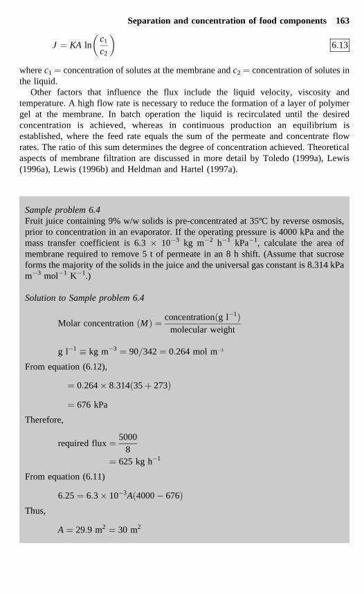
Sample problem 6.4Fruit juice containing 9% w/w solids is pre-concentrated at 35ºC by reverse osmosis,prior to concentration in an evaporator. If the operating pressure is 4000 kPa and themass transfer coefficient is 6.3 � 10�3 kg m�2 h�1 kPa�1, calculate the area ofmembrane required to remove 5 t of permeate in an 8 h shift. (Assume that sucroseforms the majority of the solids in the juice and the universal gas constant is 8.314 kPam�3 mol�1 K�1.)
Solution to Sample problem 6.4
Molar concentration �M� � concentration�g l�1�molecular weight
g l�1 � kg m�3 � 90�342 � 0�264 mol m�3
From equation (6.12),
� � 0�264 � 8�314�35 � 273�� 676 kPa
Therefore,
required flux � 50008
� 625 kg h�1
From equation (6.11)
6�25 � 6�3 � 10�3A�4000 � 676�Thus,
A � 29�9 m2 � 30 m2
Separation and concentration of food components 163

6.5.2 EquipmentThe molecular structure of reverse osmosis membranes is the main factor that controls therate of diffusion of solutes. The materials should have a high water permeability and ahigh solute rejection and durability. ‘Ultrathin’ membranes (0.05–0.1�m thick) weremade initially from cellulose acetate, mixed cellulose esters (acetate-propionate-butyrate), polyacrylonitrile, polyamides or polyurethanes (Michaels, 1974). They havethe required permeability, high stability and mechanical strength to resist the highoperating pressures. Loeb membranes are heterogeneous membranes which consist of athin layer of membrane (for example 0.1�m thick cellulose ester) on a thicker (5–10 mm)layer of porous support material. However, these materials were limited to operatingtemperatures below 30ºC and a pH range of 3–6, and were followed by newer materialsmade from polyamides and polysulphones and inorganic membranes made from sinteredor ceramic materials (Table 6.5). These are able to withstand higher temperatures (e.g.80ºC) and a wider pH range (e.g. pH 3–11).
The main requirement of an ultrafiltration membrane is the ability to form and retain a‘microporous’ structure during manufacture and operation. Rigid ceramic or glassypolymers, which are thicker than reverse osmosis membranes (0.1–0.5�m), are used.They are mechanically strong, durable and resistant to abrasion, heat and hydrolysis oroxidation in water. They do not creep, soften or collapse under pressure. Suitablematerials are described in Table 6.5. The pore size in the inner skin determines the size ofmolecules which can pass through the membrane; larger molecules are retained on theinside of the membrane. MF membranes are similar to UF membranes, having two parts:a macroporous support material and a microporous coating on the surface. Themacroporous support materials are produced from sintered materials such as alumina,carbon, stainless steel and nickel, and have a pore diameter of 10 �m or more to allow thepermeate to drain away freely. Inorganic materials such as glass and compounds of
Table 6.5 Advantages and limitations of different types of membrane for RO and UF
Type of membrane Advantages Limitations
Cellulose acetate High permeate fluxGood salt rejectionEasy to manufacture
Break down at high temperaturespH sensitive (can only operatebetween pH 3–6)Broken down by chlorine,causing problems with cleaningand sanitation
Polymers (for examplepolysulphones, polyamides,poly-vinyl chloride,polystyrene, polycarbonates,polyethers
Polyamides have better pHresistance than celluloseacetatePolysulphones have greatertemperature resistance (up to75ºC), wider pH range (1–13)and better chlorine resistance(up to 50 �g kg�1).Easy to fabricateWide range of pore sizes
Do not withstand high pressuresand restricted to ultrafiltrationPolyamides more sensitive tochlorine than cellulose acetate
Composite or ceramicmembranes (for exampleporous carbon, zirconiumoxide, alumina)
InertVery wide range of operatingtemperatures and pHResistant to chlorine and easilycleaned
Expensive
Adapted from the data of Heldman and Hartel (1997a).
164 Food processing technology

aluminium, zirconium and titanium are used for microporous component of membranes.These have good structural strength and resistance to higher temperatures and damagefrom chemicals or abrasion.
All types of membranes should be supported to resist the high pressures and themembrane plus support material are termed a ‘module’. The design criteria for modulesshould include:
• provision of a large surface area in a compact volume• configuration of the membrane to permit suitable turbulence, pressure losses, flow
rates and energy requirements• no dead spaces and capability for cleaning-in-place (CIP) on both the concentrate and
permeate sides• easy accessibility for cleaning and membrane replacement (Lewis, 1996a).
The two main configurations of membranes are the tubular and flat plate designs.Tubular membranes are held in cylindrical tubes mounted on a frame with associatedpipework and controls. The two main types are the hollow fibre and wide tube designs.Hollow fibre systems (Fig. 6.13) have 50–1000 fibres, one metre long and 0.001–1.2 mmin diameter, with membranes of about 250 �m thick. The fibres are attached at each endto a tube sheet to ensure that the feed is uniformly distributed to all tubes. These systemshave a large surface area to volume ratio and a small holdup volume. They are used forRO applications such as desalination, but in UF applications the low applied pressure andlaminar flow limits this system to low viscosity liquids that do not contain particles. Theyare also more expensive because an entire cartridge must be replaced if one or morefibres burst. However, they are easy to clean and do not block easily.
Fig. 6.13 Membrane structures: (a) asymmetrical membrane cross-section; (b) symmetricalmembrane cross-section; (c) hollow-fibre asymmetrical membrane cross-section; (d) flat sheet
asymmetrical membrane cross-section.(Courtesy of Environmental Technology Best Practice Programme.)
Separation and concentration of food components 165
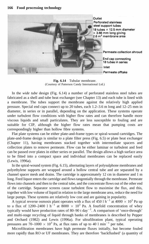
In the wide tube design (Fig. 6.14) a number of perforated stainless steel tubes arefabricated as a shell and tube heat exchanger (see Chapter 13) and each tube is lined witha membrane. The tubes support the membrane against the relatively high appliedpressure. Special end caps connect up to 20 tubes, each 1.2–3.6 m long and 12–25 mm indiameter, in series or in parallel, depending on the application. These systems operateunder turbulent flow conditions with higher flow rates and can therefore handle moreviscous liquids and small particulates. They are less susceptible to fouling and aresuitable for CIP, although the higher flow rates mean that pumping costs arecorrespondingly higher than hollow fibre systems.
Flat plate systems can be either plate-and-frame types or spiral-wound cartridges. Theplate-and-frame design is similar to a plate filter press (Fig. 6.5) or plate heat exchanger(Chapter 11), having membranes stacked together with intermediate spacers andcollection plates to remove permeate. Flow can be either laminar or turbulent and feedcan be passed over plates in either series or parallel. The design allows a high surface areato be fitted into a compact space and individual membranes can be replaced easily(Lewis, 1996a).
In the spiral-wound system (Fig. 6.15), alternating layers of polysulphone membranes andpolyethylene supports are wrapped around a hollow central tube and are separated by achannel spacer mesh and drains. The cartridge is approximately 12 cm in diameter and 1 mlong. Feed liquor enters the cartridge and flows tangentially through the membrane. Permeateflows into channels and then to the central tube, and the concentrate flows out of the other endof the cartridge. Separator screens cause turbulent flow to maximise the flux, and this,together with low volume of liquid in relation to the large membrane area, reduce the need forlarge pumps. These systems are relatively low cost and are gaining in popularity.
A typical reverse osmosis plant operates with a flux of 450 l h�1 at 4000 � 103 Pa upto a flux of 1200–2400 l h�1 at 8000 � 103 Pa. A fourfold concentration of wheytypically would have production rates of 80–90 t day�1. A comparison of ‘once-through’and multi-stage recycling of liquid through banks of membranes is described by Pepperand Orchard (1982) and Lewis (1996a). For ultrafiltration plant, typical operatingpressures are 70–1000 � 103 Pa, at flux rates of up to 40 l min�1 per tube.
Microfiltration membranes have high permeate fluxes initially, but become fouledmore rapidly than RO or UF membranes. They are therefore ‘backflushed’ (a quantity of
Fig. 6.14 Tubular membrane.(Courtesy of Patterson Candy International Ltd.)
166 Food processing technology

permeate is forced back through the membrane) to remove particles from the membranesurface. Other methods of maintaining flux levels are described by Grandison andFinnigan (1996).
6.6 Effect on foods
The unit operations described in this chapter are intended to remove components of thefood and they are used to alter or improve the sensory properties of the resulting products(for example clarification of juices, separation of cream). The effects on nutritional valueare more difficult to assess in most operations and are usually incidental to the mainpurpose of altering eating qualities. However, with the exception of some types of solvent
Table 6.6 Loss of nutrients during membrane concentration of milk
Loss (%)
Nutrient Reverse osmosis Ultrafiltration
Protein 0 5Fat 0 0Carbohydrate 0 43Energy 0 13Thiamin 0 38Riboflavin 0 39Nicotinic acid 8 41Vitamin B6 3 36Vitamin B12 0 2Vitamin C – 87Folic acid 0 5Pantothenic acid 0 32Biotin 0 37
From Glover (1971).
Fig. 6.15 Spiral cartridge membrane: (a) components; (b) schematic flow diagram.(Courtesy of Millipore Ltd.)
Separation and concentration of food components 167

extraction, these operations take place at ambient temperatures and loss of heat sensitivenutrients is not significant. The main losses occur as a result of the physical removal offood components.
In contrast to concentration by boiling (Chapter 13), reverse osmosis and ultrafiltrationmembranes concentrate foods without heat to produce good retention of sensory andnutritional qualities. For example in whey the functional properties (emulsifying ability,foaming ability and solubility) of proteins are retained, and different products which havespecified ranges of protein and lactose content can be produced for use in fortified jams,low-calorie mayonnaise, dips, sauces and skinless sausages, and as alternatives to eggalbumin (Smallwood, 1986). Concentrated orange juice prepared by reverse osmosis wasfound to be no different to a control after 43 months, whereas juice prepared by vacuum-evaporation was inferior to the control (Papanicolaou et al., 1984). Both types ofmembrane retain proteins, fats and larger carbohydrates, but the larger pore size ofultrafiltration membranes allows sugars, vitamins and amino acids to be lost (Table 6.6).
6.7 Acknowledgements
Grateful acknowledgement is made of information supplied by the following: Simon-Rosedowns Ltd, Hull HU2 0AD, UK; Westfalia Separator AG, D-4740 Oelde, Germany;Paterson Candy International Ltd, Whitchurch, Hampshire, UK; Millipore UK Ltd,Harrow, Middlesex HA1 2YH, UK; Alfa Laval Co. Ltd, Brentford, Middlesex TW8 9BT,UK; Pall Europe Ltd, Portsmouth, PO1 3PD, UK; Filtration Services Ltd, Macclesfield,Cheshire SK11 6LF, UK; Environmental Technology Best Practice Programme, UKGovernment.
6.8 ReferencesANON. (1997) Cost-effective Membrane Technologies for Minimising Wastes and Effluents, Guide GG54,
Environmental Technology Best Practice Programme, UK Government.BARKER, A. (1987) Private communication, Simon-Rosedowns Ltd, Hull, UK.BRENNAN, J. G., BUTTERS, J. R., COWELL, N. D. and LILLEY, A. E. V. (1990) Food Engineering Operations, 3rd
edn. Elsevier Applied Science, London.BROGLE, H. (1982) CO2 as a solvent: its properties and applications. Chem Ind. 12, 385–390.CLARKE, R. J. (1990) Instant coffee technology. In: A. Turner (ed.) Food Technology International Europe.
Sterling Publications International, London, pp. 137–139.EARLE, R. L. (1983) Unit Operations in Food Processing, 2nd edn. Pergamon Press, Oxford, pp. 143–158.GAEHRS, H. J. (1990) Supercritical gas extraction: optimising the economics. In: A. Turner (ed.) Food
Technology International Europe. Sterling Publications International, London, pp. 77–81.GARDNER, D. S. (1982) Industrial scale hop extraction with liquid CO2. Chem Ind. 12, 402–405.GLOVER, F. A. (1971) Concentration of milk by ultrafiltration and reverse osmosis. J. Dairy Res. 38, 373–
379.GRANDISON, A. S. (1996) Ion-exchange and electrodialysis. In: A. S. Grandison and M. J. Lewis (eds)
Separation Processes in the Food and Biotechnology Industries. Woodhead Publishing,Cambridge, pp. 155–177.
GRANDISON, A. S. and FINNIGAN, T. J. A. (1996) Microfiltration. In: A.S. Grandison and M.J. Lewis (eds)Separation Processes in the Food and Biotechnology Industries. Woodhead Publishing,Cambridge, pp. 141–153.
HELDMAN, D. R. and HARTEL, R. W. (1997a) Liquid concentration. In: D. R. Heldman and R. W. Hartel (eds)Principles of Food Processing. Chapman and Hall, New York, pp. 138–176.
HELDMAN, D. R. and HARTEL, R. W. (1997b) Other separation processes. In: D. R. Heldman and R. W. Hartel(eds) Principles of Food Processing. Chapman and Hall, New York, pp. 219–252.
HEMFORT, H. (1983) Centrifugal separators for the food industry. Westfalia Separator AG, 4740 Oelde 1,Germany.
168 Food processing technology

HEMFORT, H. (1984) Centrifugal clarifiers and decanters for biotechnology. Westfalia Separator AG, 4740Oelde 1, Germany.
JACKSON, A. T. and LAMB, J. (1981) Calculations in Food and Chemical Engineering. Macmillan, London,pp. 129–163.
JONES, H., JONES, N. and SWIENTEK, R. J. (1983) Plate and frame filters clarify apple juice. Food Process.(USA) October, 104–105.
KARLSSON, H. O. E. and TRAGARDH, G. (1996) Applications of pervaporation in food processing. Trends inFood Science & Technology 7 (March), 78–83.
LENIGER, H. A. and BEVERLOO, W. A. (1975) Food Process Engineering. D. Reidel, Dordrecht, pp. 498–531.LEWIS, M. J. (1996a) Pressure-activated membrane processes. In: A. S. Grandison and M. J. Lewis (eds)
Separation Processes in the Food and Biotechnology Industries. Woodhead Publishing,Cambridge, pp. 65–96.
LEWIS, M. J. (1996b) Ultrafiltration. In: A. S. Grandison and M. J. Lewis (eds) Separation Processes in theFood and Biotechnology Industries. Woodhead Publishing, Cambridge, pp. 97–140.
MACKINTOSH, B. (1983) Ultrafiltration for process waters. Food Process. September 29–31.MADSEN, R. F. (1974) Membrane concentration. In: A. Spicer (ed.) Advances in Preconcentration and
Dehydration of Foods. Applied Science, London, pp. 251–301.MICHAELS, A. S. (1974) Tailored membranes. In: A. Spicer (ed.) Advances in Preconcentration and
Dehydration of Foods. Applied Science, London, pp. 213–250.PAPANICOLAOU, D., KATSABOXAKIS, K. and CODOUNIS, M. (1984) Rev. Gen. de Froid 74 (4), 211–213.PEPPER, D. and ORCHARD, A. C. J. (1982) Improvements in the concentration of whey and milk by reverse
osmosis. J. Soc. Dairy Technol. 35 (2), 49–53.RIZVI, S. S. H., DANIELS, J. A., BENADO, A. L. and ZOLLWEG, J. A. (1986) Supercritical fluid extraction: operating
principles and food applications. Food Technol. 40 (7), 56–64.RIZVI, S. S. H., MULVANEY, S. J. and SOKHEY, A. S. (1995) The combined application of supercritical fluid and
extrusion technology. Trends in Food Science & Technology 6, 232–240.ROBE, K. (1983) Hyperfiltration methods for preconcentrating juice saves evaporation energy. Food
Process. (USA) 100–101.ROSENBERG, M. (1995) Current and future applications for membrane processes in the dairy industry.
Trends in Food Science & Technology 6, 12–19.SMALLWOOD, M. (1986) Concentrating on natural proteins. Food Process. September 21–22.STEIN, W. (1984) New oil extraction process. Food Engng Int. June 59, 61–63.STEYTLER, D. (1996) Supercritical fluid extraction and its application to the food industry. In: A. S.
Grandison and M. J. Lewis (eds) Separation Processes in the Food and Biotechnology Industries.Woodhead Publishing, Cambridge, pp. 17–64.
TOLEDO, R. T. (1999a) Physical separation processes. In: R. T. Toledo, Fundamentals of Food ProcessEngineering, 2nd edn. Aspen Publications, MD, pp. 507–547.
TOLEDO, R. T. (1999b) Extraction. In: R. T. Toledo, Fundamentals of Food Process Engineering, 2nd edn.Aspen Publications, MD, pp. 548–566.
VINE, R. P. (1987) The use of new technology in commercial winemaking. In A. Turner (ed.) FoodTechnology International Europe. Sterling Publications International, London, pp. 146–149.
Separation and concentration of food components 169