Embed Size (px)
Citation preview

6 Removal and replacement
Chapter contents
This chapter contains the following sections:
Chapter contents ...................................................................................................................201Introduction ............................................................................................................................204
Removal and replacement strategy ................................................................................204Repair notices .................................................................................................................204Caution regarding electrostatic discharge (ESD) ...........................................................204Required tools .................................................................................................................204Types of screws ..............................................................................................................205
Supplies .................................................................................................................................207Print cartridges and transfer unit ....................................................................................208
Covers ...................................................................................................................................209Front door removal .........................................................................................................209Left cover removal ..........................................................................................................210Left front cover removal ..................................................................................................211Right cover removal ........................................................................................................213Top cover removal ..........................................................................................................214Upper rear door removal ................................................................................................214Rear cover removal ........................................................................................................215Lower rear door (rear output bin) removal .....................................................................215Tray 1 (multipurpose) removal .......................................................................................216
Main Assemblies ...................................................................................................................217Transfer unit removal ......................................................................................................218Print cartridge removal ...................................................................................................219Fuser removal .................................................................................................................220Face-down delivery assembly removal ..........................................................................221Laser/scanner assembly removal ...................................................................................222Image drive assembly removal .......................................................................................223Developing engaging drive assembly removal ...............................................................225Pick-up/feed assembly removal .....................................................................................225
Main assembly parts .............................................................................................................236Tray 1 pick-up roller removal ..........................................................................................237Tray 1 separation pad removal .......................................................................................237Tray 2 pick-up roller removal ..........................................................................................238Tray 2 separation pad removal .......................................................................................238Secondary transfer charging roller removal ...................................................................239Fuser sleeve unit removal ..............................................................................................239Pressure roller removal ..................................................................................................239Main thermistor/sub-thermistor removal .........................................................................239Thermoswitch removal ...................................................................................................239Feed guide unit removal .................................................................................................240
ENWW Chapter contents 201

Swing guide removal, right .............................................................................................242Swing guide removal, left ...............................................................................................245
Switches ................................................................................................................................250Door Switch (SW1) removal ...........................................................................................250Test print switch (SW1001) removal ..............................................................................251Power switch (SW3001) removal ...................................................................................251
Sensors .................................................................................................................................252Tray 1 (multipurpose tray) paper sensor (PS1) removal ................................................253Tray 2 (cassette) paper sensor (PS2) removal ..............................................................253Registration paper sensor (PS4) removal ......................................................................254Media sensor (PS5) removal ..........................................................................................255Fuser front paper sensor (PS6) removal ........................................................................256Fuser delivery paper sensor (PS7) removal ...................................................................256Face-down delivery paper sensor (PS8) removal ..........................................................257Reversed paper sensor (PS9) removal (HP 3700 only) .................................................257Duplex feed delivery paper sensor (PS10) removal (HP 3700 only) .............................258Rear output bin paper sensor (PS11) removal ...............................................................259Color misregistration sensor (PS12) removal ................................................................260Waste toner level sensor (PS13) removal ......................................................................260Developing engaging sensor (PS14) removal ................................................................261Environment sensor (PS15) removal .............................................................................261Secondary transfer roller engaging sensor (PS16) removal ..........................................262
Solenoids and Clutches ........................................................................................................263Tray 1 (multipurpose tray) pick-up solenoid (SL1) removal ...........................................263Tray 2 pick-up solenoid (SL2) removal ...........................................................................264Secondary transfer roller engaging solenoid (SL4) removal ..........................................265Duplex feed solenoid (SL5) removal (HP 3700 only) .....................................................266Registration clutch (CL1) removal ..................................................................................266Black (K) development clutch (CL2 - image drive) removal ...........................................267Developing engaging drive clutch (CL3) removal ..........................................................268
Motor and fans ......................................................................................................................269Feed motor (M1) removal ...............................................................................................269Delivery motor (M2) removal ..........................................................................................271Drum motor (M3) removal ..............................................................................................271Developing motor (M4) removal .....................................................................................273Primary transfer roller engaging motor (M5) removal ....................................................274Exhaust fan (FAN1) removal ..........................................................................................277
Circuit Boards ........................................................................................................................278DC controller PCB removal ............................................................................................278Formatter PCB removal ..................................................................................................279High-voltage power supply PCB removal .......................................................................281Low-voltage power supply PCB removal .......................................................................285Memory controller PCB removal ....................................................................................286Control Panel PCB removal ............................................................................................287
Miscellaneous parts ..............................................................................................................288Swing rod guide, left removal .........................................................................................288Swing rod/lock guide, right removal ...............................................................................288Transfer contact assembly removal ...............................................................................288Developing contact assembly .........................................................................................288
Tray 2 (cassette) parts removal ............................................................................................291Tray 2 (cassette) .............................................................................................................291Cassette (Tray 2) guide, right, removal ..........................................................................291
500-Sheet paper feeder (Tray 3) covers ...............................................................................296Front cover removal - 500-sheet paper feeder ...............................................................296Right cover removal - 500-sheet paper feeder ...............................................................297Left cover removal - 500-sheet paper feeder .................................................................297
202 Chapter 6 Removal and replacement ENWW

500-Sheet paper feeder internal parts ..................................................................................298Pick-up roller removal - 500-sheet paper feeder ............................................................298Separation pad removal - 500-sheet paper feeder ........................................................299Pick-up drive unit removal - 500-sheet paper feeder .....................................................299
500-Sheet paper feeder sensor/solenoid/motor/PCB ...........................................................300500-Sheet paper feeder PCB removal - 500-sheet feeder ............................................300Pick-up clutch (CL4) removal - 500-sheet feeder ...........................................................301Pick-up solenoid (SL3) removal - 500-sheet feeder .......................................................301Paper sensor (PS3) removal - 500-sheet feeder ...........................................................302
ENWW Chapter contents 203

Introduction
Removal and replacement procedures are provided for all replaceable parts in the printer.
Removal and replacement strategyThis chapter explains how to remove and replace major printer components. (HP does notsupport repairing individual subassemblies or troubleshooting to the component level.)
Replacement is generally the reverse of removal. Occasionally, directions for difficult orcritical replacement procedures are included.
WARNING! The information in this section is intended for authorized service personnel only.
Repair notices
WARNING! Turn the printer off, wait five seconds, then unplug the power cord before servicing theprinter. Failure to completely disconnect the printer could result in severe injury.
Never operate or service the printer with the protective cover removed from the laser/scanner assembly. The reflected beam, although invisible, can damage your eyes.
Never operate the printer with any parts removed.
The sheet-metal parts can have sharp edges. Be careful not to cut yourself when handlingsheet-metal parts.
Caution regarding electrostatic discharge (ESD)The printer contains parts that are sensitive to electrostatic discharge (ESD). Watch for theESD reminder shown at the left when removing printer parts. Protect the parts that aresensitive to ESD with protective ESD pouches.
Required toolsBefore servicing the printer, gather the following tools:
● Phillips #2 magnetized screwdriver (152 mm [ (6 inch)] shaft)
● Small flat-blade screwdriver
● Small needle-nose pliers
● ESD strap
● Penlight (optional)
204 Chapter 6 Removal and replacement ENWW

NOTE All components in the HP Color LaserJet 3500/3550 and 3700 series printers use Phillips-head screws that require a #2 Phillips screwdriver. Ensure that you have a Phillipsscrewdriver and not a Posidriv screwdriver. Figure 6-1 (below) shows the difference betweena Phillips and a Posidriv screwdriver. Note that the Phillips tip has more beveled surfaces.
Figure 6-1. Phillips and Posidrive screwdriver comparison
Types of screwsTable 6-1, below, describes the screws used in the printer and provides guidelines to helpdetermine where to use each type of screw. The screws can vary in length depending on thethickness of the material being fastened.
Always note where each type of screw is located and replace each one into its originallocation.
Table 6-1. Common fasteners
Illustration Description Size Part number Use
SCREW, TP M4X6 XA9-1450-000CN
Secures metal frame panelsto metal frame panels.
SCREW, W/WASHER M3X6 XA9-1477-000CN
Secures the drawer, crossmember, to the frame (seeFigure 8-11. Internalcomponents (4 of 4)).
SCREW, W/WASHER, RS M3X6 XA9-1461-000CN
Secures motor (M2) to theframe.
SCREW W/WASHER M3X8 XA9-1420-000CN
Secures metal to metal(ground wire, feed guiderear two screws).
SCREW, W/WASHER M3X12 XA9-1452-000CN
Secures laser/scannerassembly to the metal frame.
ENWW Introduction 205

Illustration Description Size Part number Use
SCREW, RS M3X6 XA9-1499-000CN
Secures metal to metal.
SCREW, RS M3X8 XA9-1445-000CN
Secures any material(except metal) to metal.
SCREW, TP XB4-7300-805CN
Secures sensor PCB toplastic (environmental, tonerfull, color misregistration,and media).
SCREW,TAPPING,TRUSSHEAD
M4X10 XB4-7401-005CN
Secures anything to plastic.
SCREW, STEPPED M4X4.5 RC1-1624000CN
Secures the right side of thepick-up/feed assembly to theframe.
SCREW, S M3X8 XA9-1500-000CN
Secures plastic to metal:front door components, rearswing guide rail,components to center frame(see Figure 8-16. LowerFrame Assembly - HP 3700and HP 3500/3550 (2 of 2))
Table 6-1. Common fasteners (continued)
206 Chapter 6 Removal and replacement ENWW

Supplies
The customer replaces print cartridges, the fuser, and the transfer unit as they are depleted.Chapter 4 explains when to replace supplies and provides instructions on replacing them.
NOTE The printer tracks the amount of use on the customer-replaceable supplies by keeping apage count. Swapping supplies between printers might cause a misrepresentation of supplylife values and is not recommended.
If you replace either the fuser or the transfer unit when servicing the printer, and thesesupplies have not yet reached the end of their estimated life, you must reset the page countfor these supplies through the CONFIGURE DEVICE menu on the control panel. See Fuserreplacement configuration and Transfer unit (ITB assembly) replacement configuration forinstructions on resetting the transfer unit and fuser counts.
Table 6-2. Approximate replacement intervals for print cartridges
Supply item Printer message HP 3500/3550Page counts
HP 3700Pagecounts
Approximate timeperiod1
To install
Black (K) printcartridge
REPLACE BLACKCARTRIDGE
6,000 pages2 6,000 pages2 HP 3500=6 months
HP 3550/3700 =4months
See Printcartridgeremoval.
Cyan (C) printcartridge
REPLACE CYANCARTRIDGE
4,000 pages2 6,000 pages2 4 months See Printcartridgeremoval.
Magenta (M)print cartridge
REPLACE MAGENTACARTRIDGE
4,000 pages2 6,000 pages2 4 months See Printcartridgeremoval.
Yellow (Y) printcartridge
REPLACE YELLOWCARTRIDGE
4,000 pages2 6,000 pages2 4 months See Printcartridgeremoval.
1Approximate life is based on: 1,000 pages per month for the HP Color LaserJet 3500 seriesprinter and 1500 pages per month for the HP Color LaserJet 3550/3700 series printer.2Approximate average A4/letter-size page count based on approximately 5 percent coverageof individual colors.
Table 6-3. Approximate replacement intervals for supply items
Supply item Printer message HP 3500Pagecounts
HP 3550/3700Page counts
Approximate timeperiod1
To install
Image transferkit (transfer unit)
REPLACETRANSFER KIT
60,000 pages2 75,000 pages2 HP 3500 =60 months
HP 3550/3700 = 50months
SeeTransferunitremoval.
ENWW Supplies 207

Supply item Printer message HP 3500Pagecounts
HP 3550/3700Page counts
Approximate timeperiod1
To install
Image fuser kit REPLACE FUSER KIT 60,000 pages2 75,000 pages2 HP 3500 =60 months
HP 3550/3700 = 50months
See Fuserremoval.
1Approximate life is based on: 1,000 pages per month for the HP Color LaserJet 3500 seriesprinter and 1500 pages per month for the HP Color LaserJet 3550/3700 series printer.2Usage conditions and print patterns cause results to vary.
CAUTION Hewlett-Packard recommends the use of HP products in this printer. Use of non-HP products can cause problems that require service not covered by the Hewlett-Packardwarranty or service agreements.
Print cartridges and transfer unitIt is recommended that you remove the print cartridges and transfer unit when servicinginternal printer components. Place the print cartridges and transfer unit in a safe place whilethey are out of the printer.
CAUTION Grasp the print cartridges by the blue handles to avoid accidentally touching thephotosensitive drum inside each cartridge.
Do not place any items on the transfer unit or touch the transfer belt. If the belt is puncturedor otherwise damaged, print quality problems will result.
For instructions on removing the transfer unit, see Transfer unit removal and for instructionson removing the print cartridges, see Print cartridge removal.
Table 6-3. Approximate replacement intervals for supply items (continued)
208 Chapter 6 Removal and replacement ENWW

Covers
The following procedures describe removal of the printers external covers.
Figure 6-2. Cover locations
1 Left cover2 Top cover3 Front door4 Tray 1 (multipurpose tray)5 Left front door (includes control panel)6 DIMM cover (HP 3700 only)7 Right cover8 Upper rear door9 Rear cover10 Lower rear door (rear output bin)
Front door removal1. Open the front door.
2. Remove the transfer unit and the print cartridges. See Transfer unit removal and Printcartridge removal.
3. Remove the right cover, see Right cover removal.
4. Remove the left cover, see Left cover removal.
5. Remove two e-clips (1) from the front door rod bracket.
ENWW Covers 209

6. Remove two screws (2) from the right hinge (3).
Figure 6-3. Front door removal (1 of 2)
7. Remove two screws (1) from the left hinge (2).
Figure 6-4. Front door removal (2 of 2)
8. Lifting up slightly on the front door to relieve the pressure on the hinges, pull the hingesout and then remove the front door.
Reinstallation tipEach hinge is keyed and will only fit into the side from which it was removed. You maywant to initial the hinge with an "R" or "L" to identify them.
Left cover removal1. Remove three screws (1).
210 Chapter 6 Removal and replacement ENWW

2. Slide the cover back in the direction of the arrow (2) about one inch, and then pull it outaway from the printer to remove it.
Figure 6-5. Left cover removal
Left front cover removal1. Remove left cover. See Left cover removal.
2. Open the front door and remove the transfer unit. See Transfer unit removal.
3. Disconnect the control panel connector (1) and remove one screw (2). Cut the cable tiethat is connected around the cable ferrite bead (3) and the cable harness (4).
Figure 6-6. Left front cover removal (1 of 3)
4. Remove the power switch rod (1) from the power switch button (2).
ENWW Covers 211

5. If necessary to better access the area, remove the toroid from the cable. To remove thetoroid, lift up on the strip (1) and swing the top cover (2) open and then remove thetoroid from the wires.
Figure 6-7. Left front cover removal (2 of 4)
6. Unhook one claw (3) from the bottom of the cover and pull out the bottom of the cover toloosen it.
Reinstallation tipRemember to put the switch rod back into the switch button.
Figure 6-8. Left front cover removal (2 of 3)
212 Chapter 6 Removal and replacement ENWW

7. Unhook three more claws by pressing in or squeezing, at the indicated locations (1),working up from the bottom, to remove the cover (2) from the printer.
Figure 6-9. Left front cover removal (3 of 3)
Right cover removal1. Open the rear output bin and the upper rear door.
2. Remove three screws (1).
3. Pull down and out on the bottom edge of the cover (2) to release two claws, then pull outon the front edge (3) to release the additional claws and remove the cover (4).
Figure 6-10. Right cover removal
ENWW Covers 213

Top cover removal1. Open the printer front door and remove the transfer unit. See Transfer unit removal.
2. Remove the right cover. See Right cover removal.
3. Remove the left cover. See Left cover removal.
4. Remove four screws (1), unhook one claw (2), and lift the cover off the printer.
Figure 6-11. Top cover removal
Upper rear door removal1. Open the upper rear door.
2. Press in on the left hinge (1), pushing towards the right to release the hinge pin, thenpull the left side out and to the left (2) to remove the cover.
Figure 6-12. Upper rear door removal
214 Chapter 6 Removal and replacement ENWW

Rear cover removal1. Release two claws on the right side of the rear cover by inserting a flat-blade
screwdriver into each claw location (1) and twist the screwdriver to release each claw,then pull the cover out and to the right (2) to remove it.
Figure 6-13. Rear cover removal
Lower rear door (rear output bin) removal1. Open the lower rear door.
2. Press in on the left hinge (1) pushing towards the right to release the pin, then pull theleft side of the tray out and to the left (2) to remove it.
Figure 6-14. Lower rear door removal
Reinstallation tipHold the tray at about a 45 degree angle when reinstalling it.
ENWW Covers 215

Tray 1 (multipurpose) removal1. Open the Tray 1.
2. Remove two pins (1) by flexing the slotted rail (2) to release the pin.
3. Press in on the left hinge at the base as shown by the arrow, then pull the left side of thetray out and to the right to remove the tray (3).
Figure 6-15. Tray 1 removal
216 Chapter 6 Removal and replacement ENWW

Main Assemblies
The following procedures describe removal of the printer's major internal mechanicalassemblies.
Figure 6-16. Main internal assemblies
1 Fuser2 Developing engaging drive assembly3 Image drive assembly4 Pick-up/feed assembly5 Laser/scanner assembly6 Transfer unit7 Face-down delivery assembly
ENWW Main Assemblies 217

Transfer unit removal
CAUTION Do not touch the surface (5), shown in the figure below, of the image transfer belt (ITB) sinceit can cause an image defect.
NOTE If the transfer unit failed or has been replace for some reason other than reaching its end-of-life (end-of-life is indicated by a control panel message stating that the transfer unit requiresreplacement) then, in addition to replacing the unit, a configuration procedure must beperformed. For information on this configuration, refer to Chapter 8, Replacement partsconfiguration.
1. Open the front door.
218 Chapter 6 Removal and replacement ENWW

2. Hold the blue handles (1) on both sides of the transfer unit. With your right thumb, pressand hold the lever (2) on the right side handle then lift the handle up (3), followed by theleft side (4) to remove the unit.
Figure 6-17. Transfer unit removal
Reinstallation tipWhen reinstalling the transfer unit, align the two pins (1) on the left side of the door withthe two holes (2) in the left side of the transfer unit.
Figure 6-18. Transfer unit installation
Print cartridge removal1. Open the front door.
ENWW Main Assemblies 219

NOTE When performing any servicing inside the printer, all four print cartridges should be removed.
2. Do not touch the surface of the print cartridge drum (2). The cartridges have flaps thatclose when the front door is opened to protect the print drum. However, if the flaps donot close, flip them down to cover the exposed area of the print drum.
Figure 6-19. Print cartridge removal
Grasp the blue handle (1) of a cartridge and pull it slightly upward and out to remove it.
Fuser removal
WARNING! Be sure to turn the power off and unplug the power cord before removing the fuser.
When removing the fuser, wait ten minutes to allow it to cool before removing it.
NOTE If the fuser failed or has been replace for some reason other than reaching its end-of-life(end-of-life is indicated by a control panel message stating that the fuser requiresreplacement) then, in addition to replacing it, a configuration procedure must be performed.For information on this configuration, refer to Chapter 8, Replacement parts configurationReplacement parts configuration.
1. Remove the lower rear door. See Lower rear door (rear output bin) removal.
220 Chapter 6 Removal and replacement ENWW

2. Hold the release tabs on each side of the fuser by placing your thumbs on the top tabs(1) and your forefingers on the lower tabs (2). Press up on the bottom tabs (2) to releasethe assembly and pull it toward you to remove it.
Figure 6-20. Fuser removal
Face-down delivery assembly removal1. Remove the following covers:
a. Upper rear door, see Upper rear door removal.
b. Rear cover, see Rear cover removal.
c. Lower rear door, see Lower rear door (rear output bin) removal.
d. Right cover, see Right cover removal.
e. Left cover, see Left cover removal.
f. Left front cover, see Left front cover removal.
g. Top cover, see Top cover removal.
2. Remove six screws (1).
ENWW Main Assemblies 221

3. Pull the face-down assembly out slightly, disconnect one connector (2) from the back,and then remove the assembly (3).
Figure 6-21. Face-down delivery assembly removal
Laser/scanner assembly removal
CAUTION Do not disassemble the laser/scanner assembly. It is not adjustable.
Do not touch the lens on the front of the laser/scanner assembly when holding it.
1. Remove the face-down delivery assembly. See Face-down delivery assembly removal.
2. Remove the exhaust fan (FAN1) assembly. See Exhaust fan (FAN1) removal, step 9.
3. Remove one connector (1) from the left side of the laser/scanner assembly.
222 Chapter 6 Removal and replacement ENWW

4. Remove six screws (2) and pull the laser/scanner assembly out slightly, disconnect twoflat cables (3), and remove the assembly.
Figure 6-22. Laser/scanner assembly removal
Reinstallation tipConnect the connectors (see callout (3) above) first, then install the laser/scannerassembly. Ensure that the top of the laser/scanner fits into the slots first before installingthe remainder of the unit.
Image drive assembly removal
CAUTION Do not disassemble the image drive assembly.
1. Remove the right cover. See Right cover removal.
2. Push the engaging rack (1) all the way back to the right until it stops. Refer to Pick-up/feed assembly removal procedure, step 7, for additional information.
Reinstallation tipOnce the image drive assembly has been reinstalled, the engaging rack (1) must bepushed to the left, forward towards the front of the printer as far as it will go to return it toits original position. Refer to Pick-up/feed assembly removal, step 8 "Reinstallation Tip"for additional information on positioning the engaging rack.
CAUTION Incorrect installation can result in damage to the print cartridge drive pins, the image driveassembly drive pins, and the swing guide mechanism.
3. Disconnect one connector (2).
ENWW Main Assemblies 223

4. Remove five screws (3) and remove the image drive assembly (4).
Figure 6-23. Image drive assembly removalReinstallation tipWhen replacing the image drive assembly ensure that the engaging pins are in the"engaged" position (1), as shown below. They should not be in the disengaged position(2). If the pins are not in the disengaged position, turn the gear (3) in the direction of thearrow (4) until it stops.Reinstallation tipRemember, replacement procedures are removal procedure steps performed in reverseorder. It is important that step 2, above, be performed after this step (step 4) to maintaincorrect orientation of the gears and pins with respect to the engaging rack mechanism.
Reinstallation tipFor reassembly, remove the right front top cover screw (1). If this screw is not removed itcan prevent the upper left corner of the image drive assembly from seating correctly.
224 Chapter 6 Removal and replacement ENWW

Developing engaging drive assembly removal1. Remove the laser/scanner assembly. See Laser/scanner assembly removal.
2. Disconnect one connector (1).
3. Remove two screws (2) and remove the developing engaging drive assembly (3).
Reinstallation tipGear (4) may come off during this disassembly. Make sure to replace it whenreassembling.
Figure 6-24. Developing engaging drive assembly removal
Pick-up/feed assembly removal1. Remove the right cover. See Right cover removal.
2. Open the front door and remove the transfer unit. See Transfer unit removal.
3. Remove the print cartridges. See Print cartridge removal.
ENWW Main Assemblies 225

4. Remove two screws (1) and disconnect the right rod bracket (2) from the front door.
Figure 6-25. Pick-up/feed assembly removal (1 of 13)
5. Remove two screws (1) and disconnect the left rod bracket (2) from the front door.
Figure 6-26. Pick-up/feed assembly removal (2 of 13)
226 Chapter 6 Removal and replacement ENWW

6. Remove two screws (1) and remove the right swing rod arm (2).
Figure 6-27. Pick-up/feed assembly removal (3 of 13)
Reinstallation tipWhen installing the swing rod arm assembly, make sure the short rod is positioned asshown below (1).
Figure 6-28. Right swing rod arm reassembly
ENWW Main Assemblies 227

7. Push the engaging rack (1) all the way back, as shown by the arrow (2), until it stops.
Figure 6-29. Pick-up/feed assembly removal (4 of 13)
228 Chapter 6 Removal and replacement ENWW

8. Remove two screws (3) and remove the swing rod/lock guide (4), shown in the abovefigure.Reinstallation tipWhen reassembling the swing rod guide, the engaging rack (callout (1) below) should bepositioned to the back (to the right) with respect to the printer, as shown below. Theengaging rack will normally be in this back position due to the tension of the spring. Also,the gear behind the engaging rack should be turned all the way clockwise (2). Toreinstall the swing rod/lock guide, perform the following steps.
Figure 6-30. Pick-up/feed engaging rack assembly replacement (1 of 2)1. Insert the tab on the front of the swing rod/lock guide (callout (4), above) into the slotin the printer frame (5), and then swing the back into position and install the two screws(3).2. Once the swing rod/lock guide is installed, push the engaging rack all the way forward(1), until it stops. This must be done to ensure that the print cartridge engaging pins arein the disengaged position (as described below).
Figure 6-31. Pick-up/feed engaging rack assembly replacement (2 of 2)The above reassembly procedure ensures that, once the reassembly is complete, theprint cartridge engaging pins are pulled back or disengaged as shown by callout (2)below. Callout (1) shows the pins extended or in the engaged position. If the engagingpins are in the wrong position (if they are engaged) the front door will not closebecause the print cartridge drive shaft will hang up on the engaging pins when the frontdoor is closed. This can result in damage to the engaging pins, print cartridges, or theswing guide closing mechanism.
Figure 6-32. Print cartridge engaging pins replacement
ENWW Main Assemblies 229
9. Disconnect one connector (1), remove two screws (2), remove the clutch plate (3), andremove the clutch (4).
Reinstallation tipWhen reinstalling the clutch, insert the clutch onto the clutch shaft. Make sure that theslotted tab on the clutch fits into the tab (6) on the clutch plate. Also, ensure that thewhite shaft bushing (5), which is keyed, is correctly seated into the notch on the clutchplate.
Figure 6-33. Pick-up/feed assembly removal (5 of 13)
10. Disconnect three connectors (1).
11. Remove the cable (2) from the cable holders (3).
230 Chapter 6 Removal and replacement ENWW

12. Remove six screws (4) and remove the main gear plate (5).
Figure 6-34. Pick-up/feed assembly removal (6 of 13)
Reinstallation tipIf the gears come off the gear plate, reinstall them as shown in the figure below.However, when reinstalling the gear plate, it is easier to install the larger gear (callout (1)into the printer, and then install the gear plate and remaining gears.
Figure 6-35. Gear plate gear locations replacement
13. Remove gear (1) (this gear might have come off when the gear plate was removed inthe previous step). (Gear (4) might also have come off during removal of the gear platebut, should be reinstalled as shown below).
Reinstallation tipWhen reinstalling the gear plate, it is easier to install the gear (1) (shown in the figurebelow) first, and then install the gear plate and remaining gears.
ENWW Main Assemblies 231

14. Remove two screws (2) and lay the solenoid cover plate (3) down (it will still beconnected to the solenoid).
Reinstallation tipThe solenoid plate has three tabs at the bottom, one tab (5) slips under the printer sheetmetal base and the other two tabs (6) fit over the base.
Figure 6-36. Pick-up/feed assembly removal (7 of 13)
15. Disconnect one spring (1).
16. Remove two screws (2) and remove the gear unit (3).
Figure 6-37. Pick-up/feed assembly removal (8 of 13)
17. Remove two screws (1).
232 Chapter 6 Removal and replacement ENWW

18. Unhook one claw (2) and pull the Tray 2 pick-up gear (3) off the shaft.
Reinstallation tipWhen installing this gear (3) it may be necessary to hold the pick-up feed roller steadywhile inserting the gear onto the shaft.
19. Remove one screw (4) and remove the solenoid cover and solenoid (5).
Figure 6-38. Pick-up/feed assembly removal (9 of 13)
20. Lift the bushing tab (1) up slightly, rotate it in the direction of the arrow (2), and then pullboth the bushing and the Tray 2 pick-up roller shaft (3) out of the printer.
Reinstallation tipWhen reinstalling the shaft (5), it should extend out approximately 17 mm (about (5/8inch)).
21. Lift the bushing tab (4) up slightly, rotate it in the direction of the arrow (5), and then pullboth the bushing and the metal shaft (6) out of the printer. The shaft has a pin throughthe end that requires you rotate the shaft while pulling on it to release it.
Figure 6-39. Pick-up/feed assembly removal (10 of 13)
ENWW Main Assemblies 233

22. Push the right swing guide (1) all the way back.
23. Unhook two claws (2) and remove the connector cover (3). (It may be easier to unhookthe upper claw from the other side of the printer frame.)
24. Release one claw (4) and remove the right swing guide rail (5). (It may be easier tounhook the claw from the other side of the frame.)
Reinstallation tipThe swing guide rail is also secured with a screw, located on the other side of the frame,which was removed in a previous step.
Figure 6-40. Pick-up/feed assembly removal (11 of 13)
25. Release one pin (1) and remove the front left swing guide rail (2). In addition to the pin atthe back of the rail, the front is secured with sticky tape. Apply steady pressure torelease it.
Reinstallation tipWhen reinstalling the swing guide rail, insert the tab at the back in first, and then slidethe front in place. Apply a slight pressure to the front to secure the tape.
Figure 6-41. Pick-up/feed assembly removal (12 of 13)
234 Chapter 6 Removal and replacement ENWW

26. Disconnect three connectors (1).
27. Remove eight screws (2) and un-route the cable (3).
28. For the HP Color LaserJet 3500/3550 series printers, remove the pick-up/feed assembly(5); for the HP Color LaserJet 3700 series printers, release the duplex pan by pulling outon the green button (4), and then remove the pick-up/feed assembly (5).
Figure 6-42. Pick-up/feed assembly removal (13 of 13)
ENWW Main Assemblies 235

Main assembly partsThe following procedures describe removal of parts located on or around the major internalmechanical assemblies.
Figure 6-43. Main assemblies parts location1 Sub thermistor (TH2)2 Main thermistor (TH1)3 Thermoswitch (TP)4 Fuser sleeve unit5 Tray 1 (multipurpose) pick-up roller6 Tray 1 separation pad7 Tray 2 pick-up roller8 Tray 2 separation pad9 Secondary transfer charging roller10 Pressure roller11 Left swing guide12 Right swing guide13 Tray 1 guide unit14 Feed guide unit
236 Chapter 6 Removal and replacement ENWW

Tray 1 pick-up roller removal1. Remove the transfer unit. See Transfer unit removal.
2. Unhook one claw (1) and slide the idler roller (2) in the direction of the arrow.
3. Rotate the Tray 1 pick-up roller (3) upwards to release it from the shaft and lift the rollerout.
Figure 6-44. Tray 1 pick-up roller removal
NOTE Replace the separation pad whenever you replace the pick-up roller.
.
Tray 1 separation pad removal1. Remove the Tray 1 pick-up roller. See Tray 1 pick-up roller removal, above.
2. Slide the left idler roller (1) in the direction of the arrow (2).
3. Place a flat-blade screwdriver under each slot (3) and twist the screwdriver to pry thepad loose to remove it.
Figure 6-45. Tray 1 separation pad removal
NOTE Replace the pick-up roller whenever you replace the separation pad.
ENWW Main assembly parts 237

Tray 2 pick-up roller removal1. Remove Tray 2.
2. Push the roller (1) in the direction of the arrow, then remove it by pulling the right sideout (2) first.
Figure 6-46. Tray 2 pick-up roller removal
Tray 2 separation pad removal1. Remove Tray 2.
2. Remove any paper from the tray.
3. Push the lifting plate (1) down.
4. Unhook two claws (2) by pressing in on them, then lift up on the separation pad (3) toremove it.
Figure 6-47. Tray 2 separation pad removal
Reinstallation tipThe separation pad contains a spring attached to the back side of the pad. This springmust be removed and installed on the replacement pad.
238 Chapter 6 Removal and replacement ENWW

Secondary transfer charging roller removal1. Remove the transfer unit and the print cartridges. See Transfer unit removal and Print
cartridge removal.
CAUTION When handling the secondary transfer charging roller, hold the shaft and bushing; do nothold the sponge part of the roller.
2. Lift the blue handle (1) straight up, once the right side is out, continue lifting to releasethe left side and remove the roller (2).
Figure 6-48. Secondary transfer charging roller removal
Reinstallation tipWhen handling the secondary transfer charging roller, hold the shaft ends and bushings;do not hold the sponge part of the roller.
Fuser sleeve unit removalReplacement of the fuser sleeve unit requires replacement of the entire fuser. See Fuserremoval.
Pressure roller removalReplacement of the pressure roller requires replacement of the entire fuser. See Fuserremoval.
Main thermistor/sub-thermistor removalReplacement of the main thermistor and the sub thermistor requires replacement of theentire fuser. See Fuser removal.
Thermoswitch removalReplacement of the thermoswitch requires replacement of the entire fuser. See Fuserremoval.
ENWW Main assembly parts 239

Feed guide unit removal1. Release the right and left rod brackets from the front door. See Pick-up/feed assembly
removal removal procedure, steps 1 through 5.
2. Push the swing guides all the way back.
3. Remove the secondary transfer charging roller. See Secondary transfer charging rollerremoval.
4. Remove the fuser. See Fuser removal.
5. Using both hands, grasp the air duct (2) and apply pressure (by pinching the top andbottom of the duct at the locations indicated by callouts (1) to release two claws (1)located on the bottom rear of the duct. Swing the front of the air duct upwards to removeit.
Figure 6-49. Feed guide unit removal (1 of 2)
240 Chapter 6 Removal and replacement ENWW

6. Push both swing guides all the way back (1), remove four screws (2), and remove thefeed guide (3).
Figure 6-50. Feed guide removal (2 of 2)
Reinstallation tipMake sure that the drive shaft (1) on the feed guide fits correctly into the drive shaft inthe printer (2).
Figure 6-51. Feed guide/printer drive shaft connection
Reinstallation tipMake sure that the two tabs (1) at the rear of the feed guide fit into the slots (2), locatedjust in front of the fuser opening (viewed from the rear of the printer with the fuserremoved).
Figure 6-52. Feed guide unit tab locations
ENWW Main assembly parts 241

Swing guide removal, right1. Open the front door and remove the transfer unit and the print cartridges. See Transfer
unit removal and Print cartridge removal.
2. Remove the top cover. See Top cover removal.
3. Remove the print cartridges. See Print cartridge removal.
4. Remove two screws (1) from the right rod bracket (2) to release the bracket from thedoor.
Figure 6-53. Right swing guide removal (1 of 4)
5. Remove two screws (1) and remove the swing rod arm (2).
Figure 6-54. Right swing guide removal (2 of 4)
242 Chapter 6 Removal and replacement ENWW

6. Push the swing guide (1) in as far as it will go.
Figure 6-55. Right swing guide removal (3 of 4)
7. Remove one spring (1) and then pull the developing (drum) lock arm (2) off its shaft.
Figure 6-56. Right swing guide removal (4 of 4)
8. Remove the right, front swing guide rail, see Pick-up/feed assembly removal, step 24.Make sure to remove the screw that secures the rail (screw (1) mentioned in step 19 ofthe Pick-up/feed assembly removal procedure).
ENWW Main assembly parts 243

9. Pull the swing guide (1) toward you as far as it will go. Then move it slightly to the left(this allows it to be pulled forward a little more), and pull it forward until it stops. Now,pull the swing guide to the left to remove it. The swing guide should pull out easily. Donot force the guide because it is fragile.
NOTE The swing guide has a retainer (1) that holds the swing guide shaft (2) in place. This retainerprevents the swing guide from being removed until the guide is all the way forward as showin the figure below. (This view is hidden by the image drive assembly and cannot be seenunless that assembly has been removed.)
Figure 6-57. Swing guide shaft removal
Reinstallation tipMake sure the developing (drum) lock arms (1) are in the upright, latched (2) positionbefore reinstalling the swing guide and pushing it back. (In the figure below the top arm(3) is unlatched and the lower arm (1) is correctly latched.) If these arms are in theunlocked position, they will prevent the swing guide from moving back. Also, these armswill occasionally unlatch while pushing the swing guide back, preventing the guide frombeing moved back. If that occurs, pull the swing guide forward, reach behind the guide,and relatch the lock arms.
Figure 6-58. Developing (drum) lock arm position for swing guide installation
244 Chapter 6 Removal and replacement ENWW

Swing guide removal, left1. Remove the high-voltage power supply PCB. See High-voltage power supply PCB
removal.
2. Remove the cables (1) from the cable harness (2).
3. Remove the screw (4) from the bracket (3), and remove the metal bracket.
Figure 6-59. Left swing guide removal (1 of 6)
ENWW Main assembly parts 245

4. Remove three screws (1) and swing the cable harness (2) to the right. The cableharness does not need to be completely removed to remove the transfer contactassembly. However, if the cable harness needs to be removed, disconnect the cableconnector (3) from the back of the harness to remove the harness.
Reinstallation tipThe power switch rod (4) rides in a slot at the bottom of the cable harness. Whenreinstalling the cable harness, make sure the switch rod is inserted in this slot.
Figure 6-60. Left swing guide removal (2 of 6)
5. Remove one screw (1) and unhook three claws (2) to remove the transfer contactassembly (3).
Reinstallation tipWhen installing the transfer contact assembly, make sure that the plastic tab (4) fitsunder the metal tab (5) and that the door switch (SW1) is in place.
Figure 6-61. Left swing guide removal (3 of 6)
246 Chapter 6 Removal and replacement ENWW

6. Remove two screws (1) and remove the left swing rod arm (2).
Figure 6-62. Left swing guide removal (4 of 6)
7. Push the left swing guide (1) in, as far as it will go (2).
Figure 6-63. Left swing guide removal (5 of 6)
ENWW Main assembly parts 247

8. Remove one spring (1) and remove the developing (drum) lock arm (2).
Figure 6-64. Left swing guide removal (6 of 6)
9. Remove the white left swing guide rail. See Pick-up/feed assembly removal, step 25.
10. Pull the left swing guide (1) toward the front of the printer.
248 Chapter 6 Removal and replacement ENWW

11. Remove the swing guide by pulling it to the right, being careful not to force it. The guidemust be positioned all the way forward to release the catch on the shaft, which will allowthe swing guide to be removed.
Reinstallation tipMake sure the projected part at the bottom of the swing guide is placed into the guide rail.
Reinstallation tipMake sure the developing (drum) lock arms (1) are in the upright, latched (2) position (asshown in the figure below), before reinstalling the swing guide. If these arms are in theunlocked position, they will prevent the swing guide from moving back. Also, whilepushing the swing guide back, these arms will occasionally unlatch, preventing the guidefrom being moved back. If that occurs, reach behind the swing guide and relatch the lockarms.
Figure 6-65. Left swing guide replacement
ENWW Main assembly parts 249

Switches
Figure 6-66. Switch locations
SW1 Door switchSW1001Test print switchSW3001Power switch
Door Switch (SW1) removal1. Refer to the left swing guide removal procedure, steps 1 through 5, and remove the
transfer contact assembly. See Swing guide removal, left.
2. Remove the door switch (1) by sliding it out.
Figure 6-67. Door switch removal
250 Chapter 6 Removal and replacement ENWW

Test print switch (SW1001) removalReplacing the test print switch requires the replacement of the DC controller PCB. See DCcontroller PCB removal.
Power switch (SW3001) removalReplacing the power switch requires replacement of the low-voltage power supply PCB. SeeLow-voltage power supply PCB removal.
ENWW Switches 251

Sensors
Figure 6-68. Sensor locations
PS1 Tray 1 (multipurpose) paper sensorPS2 Tray 2 (cassette) paper sensorPS4 Registration paper sensorPS5 Media sensorPS6 Fuser front paper sensorPS7 Fuser delivery paper sensorPS8 Face-down delivery paper sensorPS9 Reversed paper sensorPS10 Duplexing feed delivery paper sensorPS11 Face-up tray sensorPS12 Color misregistration sensorPS13 Waste toner level sensorPS14 Developing engaging sensorPS15 Environment sensorPS16 Secondary transfer roller engaging sensor
252 Chapter 6 Removal and replacement ENWW

Tray 1 (multipurpose tray) paper sensor (PS1) removalReplacement of the Tray 1 paper sensor requires replacement of the entire pick-up/feedassembly. See Pick-up/feed assembly removal.
Tray 2 (cassette) paper sensor (PS2) removal1. Remove the pick-up/feed assembly. See Pick-up/feed assembly removal.
2. Turn the pick-up/feed assembly over.
3. Remove the Tray 2 pick-up roller (1) by pushing in on the right side (2) of the roller unitand then pull it out and to the right (3) to remove it.
Figure 6-69. Tray 2 paper sensor removal (1 of 3)
Reinstallation tipWhen installing the sensor, connect the connector first, then install the sensor.
4. Unhook the bushing claw (1) by pushing it in, then rotate it in the direction of the arrow(2), and remove both the bushing (3) and black sensor arm (4).
Figure 6-70. Tray 2 paper sensor removal (2 of 3)
Reinstallation tipMake sure that the flag on the sensor arm (4 - in the above figure) fits between the notchin the paper sensor (5 - in the above figure) and moves freely.
ENWW Sensors 253

5. Unhook two claws (1) and pull the paper sensor (2) out, disconnecting the connector (3)once the sensor is pulled away from the assembly.
Figure 6-71. Tray paper sensor removal (3 of 3)
Reinstallation tipWhen reinstalling the sensor, connect the connector first then, install the sensor.
Registration paper sensor (PS4) removal1. Remove the pick-up/feed assembly. See Pick-up/feed assembly removal.
2. Remove one screw (1) and remove the registration paper sensor holder (2).
Figure 6-72. Registration paper sensor removal (1 of 2)
254 Chapter 6 Removal and replacement ENWW

3. Unhook two claws (1), disconnect one connector (2), and remove the registration papersensor (3) from the sensor holder.
Figure 6-73. Registration paper sensor removal (2 of 2)
Media sensor (PS5) removal
NOTE When the media sensor is replaced, in addition to replacing the sensor, a configurationprocedure must be performed. For information on this configuration, refer to Chapter 8,Replacement parts configuration.
1. Remove the color misregistration sensor. See Color misregistration sensor (PS12)removal.
2. Disconnect one connector (1).
3. Swing the front side of the media sensor upward (2), then lift the sensor (4) up, removingit from the two shafts (3).
Figure 6-74. Media sensor removal
ENWW Sensors 255
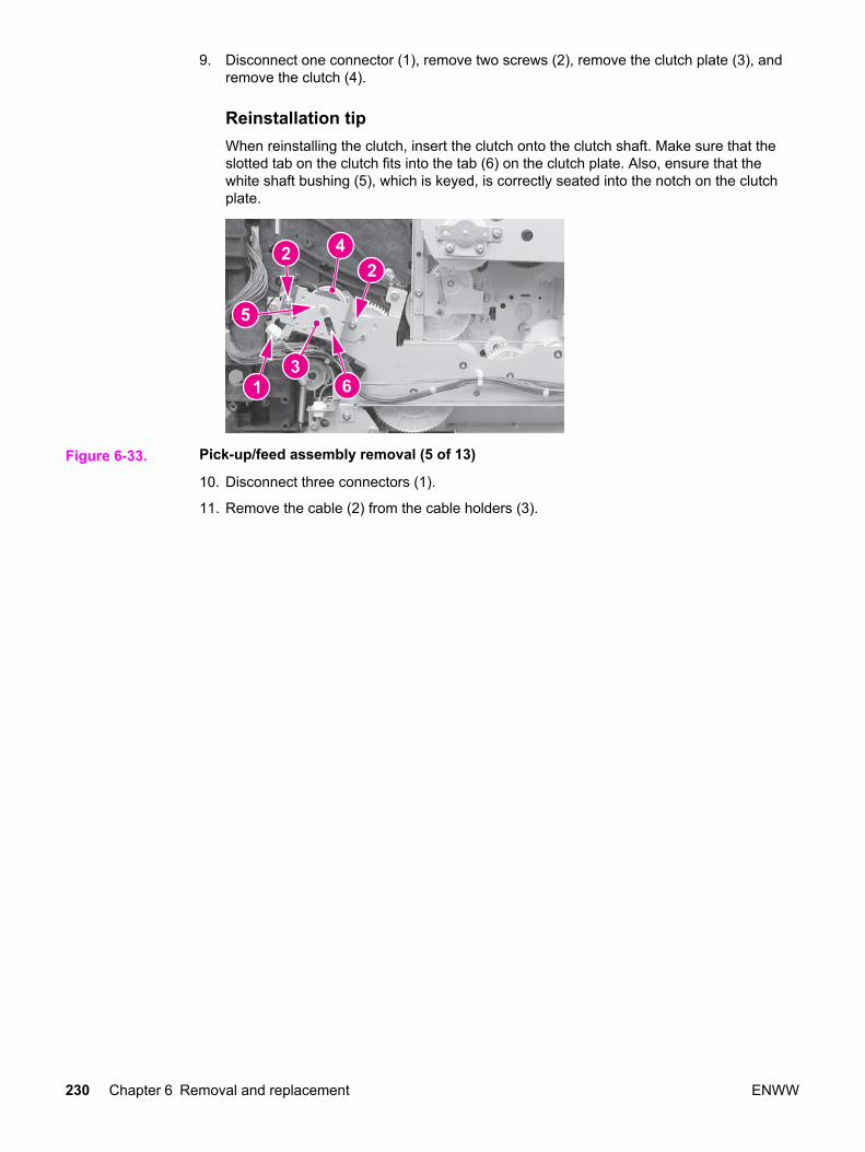
Fuser front paper sensor (PS6) removal1. Remove the feed guide unit. See Feed guide unit removal.
2. Disconnect one connector (1), unhook two claws (2), and remove the sensor (3).
Figure 6-75. Fuser front paper sensor (PS6) removal
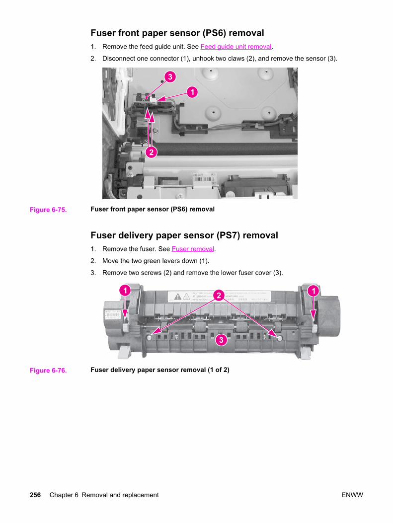
Fuser delivery paper sensor (PS7) removal1. Remove the fuser. See Fuser removal.
2. Move the two green levers down (1).
3. Remove two screws (2) and remove the lower fuser cover (3).
Figure 6-76. Fuser delivery paper sensor removal (1 of 2)
256 Chapter 6 Removal and replacement ENWW

4. Disconnect one connector (1), unhook two claws (2), and remove the fuser deliverypaper sensor (3).
Figure 6-77. Fuser delivery paper sensor removal (2 of 2)
Face-down delivery paper sensor (PS8) removal1. Remove the face-down (output bin) delivery assembly. See Face-down delivery
assembly removal.
2. Unhook two claws (1) and remove the face-down delivery paper sensor (2).
Figure 6-78. Face-down (output bin) delivery paper sensor removal
Reversed paper sensor (PS9) removal (HP 3700 only)1. Remove the fuser. See Fuser removal.
2. Remove two screws (1) and remove the reverse guide unit (2).
ENWW Sensors 257

3. Loosen the right printer Tray 2 guide. See Cassette (Tray 2) guide, right, removal(HP 3500/3550).
Figure 6-79. Reversed paper sensor removal (1 of 2)
4. Remove one connector (1), unhook two claws (2), and remove the sensor (3). In thisillustration below the Tray 2 right rail guide is shown attached but is loose, allowing youto remove it to access the back side of the sensor to release the two claws from behind.
Figure 6-80. Reversed paper sensor removal (2 of 2)
Duplex feed delivery paper sensor (PS10) removal (HP 3700only)1. Remove the feed guide. See Feed guide unit removal.
2. Disconnect one connector (1) and remove the cables from the cable guide. Lift up on theclaw (2), slide the cable guide/sensor holder assembly back (3), then lift it up to release it.
258 Chapter 6 Removal and replacement ENWW

3. Unhook two claws from the back and remove the sensor (4).
Figure 6-81. Duplex feed delivery paper sensor removal
Rear output bin paper sensor (PS11) removal1. Remove the face-down delivery assembly. See Face-down delivery assembly removal.
2. Disconnect one connector (1) and unhook two claws (2). To unhook the claws, insert apointed object into the two claw locations (2), (under the sensor at the connector side ofthe sensor), to release the claws, then lift up on the connector side of the sensor (3) toremove it.
Figure 6-82. Rear output bin paper sensor removal
ENWW Sensors 259

Color misregistration sensor (PS12) removal
NOTE When the color misregistration sensor is replaced, in addition to replacing the sensor, aconfiguration procedure must be performed. For information on this configuration, refer toChapter 8, Replacement parts configuration.
1. Refer to the pick-up/feed unit removal procedure, steps 1 through 5, and release theright and left slide rods from the front door. See Pick-up/feed assembly removal.
2. Push the swing guides in as far as they will go.
3. Refer to the pick-up/feed unit removal procedure, steps 22 through 25, and remove theconnector cover and the right and left swing guide rails. See Pick-up/feed assemblyremoval.
4. Disconnect one connector (1).
5. Remove one screw (2), the shaft holder (3), and the spring under the shaft holderlocated directly under the screw (2).
6. Unhook two claws (4) and lift the color misregistration sensor (5) up to remove it.
Figure 6-83. Color misregistration sensor removal
Waste toner level sensor (PS13) removal1. Remove the front left cover. See Left front cover removal.
2. Remove one connector (1) from the DC controller PCB and unroute the cable.
260 Chapter 6 Removal and replacement ENWW

3. Remove one screw (2) and remove the waste toner level sensor (3).
Figure 6-84. Waste toner level sensor removal
Developing engaging sensor (PS14) removal1. Remove the laser/scanner assembly. See Laser/scanner assembly removal.
2. Disconnect one connector (1), unhook two claws (2), and remove the developingengaging sensor (3).
Figure 6-85. Developing engaging sensor removal
Environment sensor (PS15) removal1. Remove the left cover. See Left cover removal.
ENWW Sensors 261

2. Remove one (1) screw and remove the sensor (2). Disconnect the connector (3) whileremoving the sensor.
Figure 6-86. Environmental sensor removal
Secondary transfer roller engaging sensor (PS16) removal1. Remove the pick-up/feed assembly. See Pick-up/feed assembly removal.
2. Turn the assembly upside down.
3. Remove the cable (1) from the cable guides. Using one hand, gently push two claws (2)apart. With your other hand, pull the sensor (3) out by holding the cable connector (4).Disconnect the connector to remove the sensor.
Figure 6-87. Secondary transfer roller engaging sensor removal
262 Chapter 6 Removal and replacement ENWW

Solenoids and Clutches
Figure 6-88. Solenoid and clutch locations
SL1 Tray 1 pick-up solenoidSL2 Tray 2 pick-up solenoid (pick-up/feed assembly)SL3 Tray 3 pick-up solenoid (not shown; see 500-sheet paper feeder)SL4 Secondary transfer roller engaging solenoidSL5 Duplex feed solenoidCL1 Registration clutchCL2 K development clutch (image drive unit)CL3 Developing engaging clutch (developing engaging drive unit)CL4 Tray 3 pick-up clutch (not shown; see 500-sheet paper feeder)
Tray 1 (multipurpose tray) pick-up solenoid (SL1) removal1. Remove the pick-up/feed assembly. See Pick-up/feed assembly removal.
ENWW Solenoids and Clutches 263

2. Remove one screw (1), disconnect one connector (2), and remove the Tray 1 pick-upsolenoid (3).
Figure 6-89. Tray 1 pick-up solenoid removal
Tray 2 pick-up solenoid (SL2) removal1. Remove the right cover. See Right cover removal.
2. Refer to the Pick-up/feed assembly removal procedure, steps 4 and 6 through 10, andremove the paper drive gear plate.
3. Remove two screws (1), disconnect one connector (2), and remove the cover plate (3).
Figure 6-90. Tray 2 pick-up solenoid removal (1 of 2)
264 Chapter 6 Removal and replacement ENWW

4. Remove one screw (1) and remove the solenoid (2).
Figure 6-91. Tray 2 pick-up solenoid removal (2 of 2)
Secondary transfer roller engaging solenoid (SL4) removal1. Remove the pick-up/feed assembly. See Pick-up/feed assembly removal.
2. Remove five screws (1), the gear side plate (2), plate (3), solenoid (4), and theconnector cover (5).
Figure 6-92. Secondary transfer roller engaging solenoid removal (1 of 2)
ENWW Solenoids and Clutches 265

3. Disconnect one connector (1), remove one screw (2), and remove the secondarytransfer roller engaging solenoid (3).
Figure 6-93. Secondary transfer roller engaging solenoid removal (2 of 2)
Duplex feed solenoid (SL5) removal (HP 3700 only)1. Remove the right 250-sheet tray guide. See Cassette (Tray 2) guide, right, removal
(HP 3700).
2. Disconnect one connector (1), remove one screw (2), and remove the duplex feedsolenoid (3).
Figure 6-94. Duplex feed solenoid removal
Registration clutch (CL1) removal1. Remove the right cover. See Right cover removal.
266 Chapter 6 Removal and replacement ENWW

2. Disconnect one connector (1), remove two screws (2), and remove the plate (3).
Figure 6-95. Registration clutch removal (1 of 2)
3. Remove the bushing (1) and remove the registration clutch (2). The bushing needs to beused for the replacement clutch.
Figure 6-96. Registration clutch removal (2 of 2)
Reinstallation tipDo not forget to reinstall the bushing (1) removed from the previous clutch. The bushingis keyed and fits into the clutch plate one way. Also, the slotted metal tab on the clutch(3) (in the figure above) fits on clutch plate's metal tab (4) (see the previous figure).
Black (K) development clutch (CL2 - image drive) removal1. Remove the image drive unit. See Image drive assembly removal.
ENWW Solenoids and Clutches 267

2. Disconnect one connector (1), remove the e-clip (2), and remove the black developmentclutch (3).
Figure 6-97. Black development clutch removal (2 of 2)
Developing engaging drive clutch (CL3) removal1. Remove the developing engaging drive assembly. See Developing engaging drive
assembly removal.
2. Remove the e-ring (1) and remove the developing engaging drive clutch (2).
Figure 6-98. Developing engaging drive clutch removal
268 Chapter 6 Removal and replacement ENWW

Motor and fans
Figure 6-99. Motor and fan locations
M1 Feed motorM2 Delivery motorM3 Drum motorM4 Developing motorM5 Primary transfer roller engaging motorFAN1 Exhaust fan
Feed motor (M1) removal1. Remove the right swing guide. See Swing guide removal, right.
2. Remove the feed guide. See Feed guide unit removal.
ENWW Motor and fans 269

3. Press down on the motor cover claw (1) and lift up on the cover (2) to remove it. Ifpossible, release the cover claw (1) from the other side of the frame.
Figure 6-100. Feed motor removal (1 of 3)
4. Disconnect one connector (1) and release the cable guide (2) by pressing in on the claw(3). Move the guide to the side (the cables can remain in the guide).
Figure 6-101. Feed motor removal (2 of 3)
270 Chapter 6 Removal and replacement ENWW

5. Remove two screws (1) and remove the feed motor (2).
Figure 6-102. Feed motor removal (3 of 3)
Delivery motor (M2) removal1. Remove the right cover. See Right cover removal.
2. Remove one connector (1).
3. Remove two screws (2) and remove the delivery motor (3).
Figure 6-103. Delivery motor removal
Drum motor (M3) removal1. Remove the image drive assembly. See Image drive assembly removal.
ENWW Motor and fans 271

2. Remove five screws (1), remove the gear plate (2), and remove two gears (3).
Figure 6-104. Drum motor removal (1 of 3)
3. Remove the face-down delivery assembly. See Face-down delivery assembly removal.
4. Remove the laser/scanner assembly. See Laser/scanner assembly removal.
5. Disconnect two connectors (1), remove two screws (2), and remove the developingengaging sensor unit (3) located next to the drum motor (4).
Figure 6-105. Drum motor removal (2 of 3)
272 Chapter 6 Removal and replacement ENWW

6. Remove four screws (1) and remove the drum motor (see callout (4) in the previousfigure).
Figure 6-106. Drum motor removal (3 of 3)
Developing motor (M4) removal1. Remove the image drive assembly. See Image drive assembly removal.
2. Remove the face-down delivery assembly. See Face-down delivery assembly removal.
3. Remove the laser/scanner assembly. See Laser/scanner assembly removal.
4. Remove the e-ring (1) and one gear (2).
Figure 6-107. Developing motor removal (1 of 3)
ENWW Motor and fans 273

5. Remove four screws (1).
Figure 6-108. Developing motor removal (2 of 3)
6. Disconnect one connector (1) and remove the developing motor (2).
Figure 6-109. Developing motor removal (3 of 3)
Primary transfer roller engaging motor (M5) removal1. Remove the image drive assembly. See Image drive assembly removal.
CAUTION It is important to refer to the image driver assembly removal procedure's "Reinstallationnotes" to ensure correct installation of this assembly. If reassembly is not performedcorrectly, it can result in damage to the print cartridge drive pins, the image drive assemblydrive pins, and the swing guide mechanism.
2. Remove the right swing guide. See Swing guide removal, right.
274 Chapter 6 Removal and replacement ENWW

3. Refer to the pick-up/feed guide assembly removal procedure, steps 1 through 12, andremove the right side gear plate. See Pick-up/feed assembly removal.
CAUTION It is important to refer to the pick-up/feed assembly removal procedure's "Reinstallationnotes" to ensure correct installation of this assembly. If reassembly is not performedcorrectly, it can result in damage to the print cartridge drive pins, the image drive assemblydrive pins, and the swing guide mechanism.
4. Remove the e-clip (1), remove two screws (2), and then remove the gear plate (3).
Reinstallation tipWhen reinstalling the gear plate, ensure that the gear (4) is turned all the waycounterclockwise as shown below. Refer to the above caution for reinstallationinformation.
Figure 6-110. Primary transfer roller engaging motor removal (1 of 4)
5. Remove the one screw (1) from the rear swing guide rail (2) and remove the rail.
6. Pull gear (3) and its shaft out to the left.
ENWW Motor and fans 275

7. Remove the motor cover (4) by pressing down on the tab (5) while pulling the coverslightly to the left and up, then pull it and out to remove it.
Figure 6-111. Primary transfer roller engaging motor removal (2 of 4)
8. Remove the gear (1) and then remove two screws that secure the motor.
Reinstallation tipWhen reinstalling the gear (1), insert the gear with shaft that was removed in theprevious step (callout (3) in the figure above) from inside the printer, through this gear.
Figure 6-112. Transfer roller engaging motor removal (3 of 4)
276 Chapter 6 Removal and replacement ENWW

9. Disconnect one connector (1) and lift the primary transfer roller engaging motor (2) upslightly, and then pull it to the left to remove it.
Figure 6-113. Transfer roller engaging motor (4 of 4)
Exhaust fan (FAN1) removal1. Remove the left cover. See Left cover removal.
2. Remove two connectors (1) from the DC controller PCB.
3. Unhook four claws (2) and pull the fan motor (3) out to remove it.
Figure 6-114. Fan removal
Reinstallation tipBe sure the arrow on the fan points to the outside when reinstalling the exhaust fan.
ENWW Motor and fans 277

Circuit Boards
Figure 6-115. Circuit board locations
1 DC controller PCB2 Memory controller PCB3 High-voltage power supply PCBs4 Low-voltage power supply PCB5 Formatter PCB6 Control panel PCB
DC controller PCB removal
NOTE When the DC controller PCB is replaced, in addition to replacing the PCB, a configurationprocedure must be performed. For information on this configuration, refer to Chapter 8,Replacement parts configuration.
1. Remove the left cover. See Left cover removal.
2. Disconnect all cable connections (19 connectors for the HP Color LaserJet 3500/3550series printer and 20 connectors for the HP Color LaserJet 3700 series printer).
278 Chapter 6 Removal and replacement ENWW

3. Remove four screws (1) and remove the PCB (2).
Figure 6-116. DC controller PCB removal
Formatter PCB removalThe HP Color LaserJet 3500/3550 series printer and the HP Color LaserJet 3700 seriesprinter have different formatter PCBs and formatter enclosures. The removal procedure forthe PCB is different as described below.
NOTE When the formatter PCB is replaced, in addition to replacing the PCB, a configurationprocedure must be performed. For information on this configuration, refer to Chapter 8,Replacement parts configuration.
1. Remove the left front cover. See Left front cover removal.
2. For the HP Color LaserJet 3500/3550 series printer, perform steps "a" and "b", below;for the HP Color LaserJet 3700 series printer, perform steps "c" and "d", below:
ENWW Circuit Boards 279

a. Disconnect two connectors (1), remove five screws (2), and remove the formatterenclosure cover (3).
Figure 6-117. Formatter PCB (HP 3500/3550) removal (1 of 2)
b. Remove seven screws (1) and remove the formatter PCB (2).
Figure 6-118. Formatter PCB (HP 3500/3500) removal (2 of 2)
c. Remove the network interface card (if installed).
280 Chapter 6 Removal and replacement ENWW

d. Disconnect one connector (1), remove two screws (2), and remove the formattercover (3).
Figure 6-119. Formatter PCB (HP 3700) removal (1 of 2)
3. Disconnect one connector (1), remove six screws (2), and remove the formatter PCB (3).
Figure 6-120. Formatter PCB (HP 3700) removal (2 of 2)
High-voltage power supply PCB removal1. Remove the top cover. See Top cover removal.
2. Remove the upper rear door. See Upper rear door removal.
3. Remove the rear cover. See Rear cover removal.
4. Remove the lower rear door. See Lower rear door (rear output bin) removal.
ENWW Circuit Boards 281

5. Disconnect two cables (1). (The formatter cage removal for the HP Color LaserJet3500/3550 and 3700 series printers is slightly different. (Refer to the figure below, eitherHP 3500/3550 or the HP 3700 for the specific printer formatter cage being removed.)
6. Remove four screws (2) from the side of the cage.
Figure 6-121. HP 3500/3550 and HP 3700
Figure 6-122. High-voltage power supply PCB removal (1 of 5)
7. Remove the screws from the back of the formatter cage (the HP 3500/3550 is shown forboth the HP 3500/3550 and HP 3700); remove two screws (1) for the HP 3500/3550;remove three screws, (1) and (2), for the HP 3700).
282 Chapter 6 Removal and replacement ENWW

8. Remove the formatter cage (3) (while removing the cage for the HP 3500/3550, releasethe cable tie (4).
Figure 6-123. High-voltage power supply PCB removal (2 of 5)
9. Disconnect two connectors (1), remove two screws (2), press down on the claw (3), andpull the fan assembly (4) out from the printer.
Figure 6-124. High-voltage power supply PCB removal (3 or 5)
10. Disconnect the remaining cable connectors from the PCB (19 connectors for theHP 3500/3550 and 20 for the HP 3700) and remove the cables from three cable clamps(1).
ENWW Circuit Boards 283

11. Remove four screws (2) and remove the DC controller PCB/plate (3) from the printer.While removing the controller PCB/plate, remove the cables from the remaining harnessclamps.
Figure 6-125. High-voltage power supply PCB removal (4 of 5)
12. Remove three screws (1), unhook eight claws (2) (working from the top down), pull outon the bottom sides of the PCB to release two pins (3), and then lift up to release it fromthe lower support (4). Once the PCB is released from the printer, disconnect theconnector (5) as you pull the PCB away from the printer.
Reinstallation tipWhen reinstalling the high-voltage power supply PCB, connect the connector (5) first.Next, install the bottom of the PCB into the bottom support (4), then align the board ontothe two lower pins (3), and working upward, hook the claws (2) on each side of theboard. Ensure that the board is aligned so it fits on the upper alignment pin (6).
6
Figure 6-126. High-voltage power supply PCB removal (5 of 5)
284 Chapter 6 Removal and replacement ENWW

Low-voltage power supply PCB removal1. Remove the formatter. See Formatter PCB removal.
2. Remove two screws (1).
3. Pull the low-voltage power supply PCB toward you about two inches. Disconnect theswitch rod (2) from the power switch on the PCB as you pull it out.
Reinstallation tipRemember to put the switch rod back into the power switch when reassembling thepower supply unit.
Figure 6-127. Low voltage power supply PCB removal (1 of 2)
If necessary, you may need to remove the toroid from the cable to allow better access tothe area at the front of the PCB. To remove the toroid, lift up on the strip (1) and swingthe top (2) open and then remove the toroid from the wires.
Figure 6-128. Left front cover removal (2 of 4)
ENWW Circuit Boards 285

4. Disconnect four connectors (1) and remove the power supply (2).
Figure 6-129. Low voltage power supply PCB removal (2 of 2)
Memory controller PCB removal1. Open the front door, remove the transfer unit, and the print cartridges. See Transfer unit
removal and Print cartridge removal.
2. Disconnect the left rod bracket from the front door by removing two screws from thebracket. See Pick-up/feed assembly removal, step 4.
3. Remove two screws (1) and pull the shield plate (2) out. Adjust the position of the swingguide, as required to access the screws. (The left swing guide has been removed forclarity in illustrating this removal procedure. It is not necessary to remove the swingguide to remove this PCB.)
Figure 6-130. Memory controller PCB removal (1 of 2)
286 Chapter 6 Removal and replacement ENWW

4. Release one claw (1) at the top of the PCB (2) and swing the right side of the PCB out(3). Then pull it to the right to free it from the retainer tab (4) and support tab (5).Disconnect the cable (6) at the top as you remove the PCB.
Reinstallation tipWhen installing the memory controller PCB, install the cable first, then set the PCB onthe bottom tab (5) (shown in the figure above). Then insert the PCB under the retainertab (4), and ensure that the alignment pin (7) is positioned in the PCB alignment hole.
7
Figure 6-131. Memory controller PCB removal (2 of 2)
Control Panel PCB removal1. Remove the left front cover. See Left front cover removal.
2. Remove three screws (1) and remove the control panel PCB assembly (2).
Figure 6-132. Control panel PCB removal
ENWW Circuit Boards 287

Miscellaneous parts
This section describes replacement for those parts not described in other sections.
Swing rod guide, left removal1. Remove the left swing guide. See Swing guide removal, left.
2. Remove the ground (1) wire from the guide. Use needle-nose pliers to pull the groundwire out of the contact (2).
Reinstallation tipRemember to reconnect the ground wire to the contact (2). Use needle nose pliers toinsert the wire back into the clip.
3. Remove the cables (3) from the guide.
4. Remove one screw (4) and pull the back end of the swing guide (5) out slightly. Thenpull it to the left to remove the front tab (6) from the slot in the front.
Swing rod/lock guide, right removalTo remove the right swing rod guide, refer to the Pick-up/feed assembly removal, steps 1through 8.
Transfer contact assembly removalTo remove the transfer contact assembly, refer to Swing guide removal, left, steps 1 through5.
Developing contact assembly1. Remove the high-voltage power supply PCB. See Exhaust fan (FAN1) removal.
288 Chapter 6 Removal and replacement ENWW

2. Remove three springs (1) from inside, located under the left swing guide. (The left swingguide is not shown for illustration purposes only.) Remove these springs carefully; theyare delicate and can be easily damaged.
Figure 6-133. Developing contact assembly removal (1 of 3)
3. Remove the plastic cover (1) by pressing in on two tabs (2) and pulling the cover out ofthe printer.
Figure 6-134. Developing contact assembly removal (2 of 3)
4. Unhook the cables from the left side cable guides (1) on the contact assembly.
ENWW Miscellaneous parts 289

5. Pull out on the top of the assembly while pressing in on two tabs (2). Once the top isreleased, pull up slightly and outward to remove the developing contact assembly (3). Asyou remove the assembly, unroute the grounding wire (4).
Reinstallation tipWhen installing the developing contact assembly, install the tab at the bottom of theassembly into the slot in the frame, then insert and latch the two tabs (2) at the top.
Figure 6-135. Developing contact assembly removal (3 of 3)
290 Chapter 6 Removal and replacement ENWW

Tray 2 (cassette) parts removal
The following section describes the removal procedures for Tray 2 and associated parts,including the right guide in the printer.
Tray 2 (cassette)The separation pad and the end plate are the only replaceable components on the tray.Replacement of any other component requires replacement of the entire tray. Forreplacement of the separation pad, see Tray 2 separation pad removal. For replacement ofthe tray or the end plate, refer to Chapter 8, Parts and diagrams, for the location of the endplate.
Cassette (Tray 2) guide, right, removalThe removal of the right guide is different for the HP Color LaserJet 3500 and 3700 seriesprinters. These procedures are provided below.
Cassette (Tray 2) guide, right, removal (HP 3700)1. Remove the transfer unit and the print cartridges. See Transfer unit removal and Print
cartridge removal.
2. Remove the lower rear door. See Lower rear door (rear output bin) removal.
3. Remove the fuser. See Fuser removal.
4. Remove the paper drive gear plate and the paper drive gear and shaft. See Pick-up/feedassembly removal, steps 1 through 12.
5. Remove the left cover. See Left cover removal.
6. Remove two screws (1) and remove the duplex guide (2) from the back of the printer.
Figure 6-136. Right Tray 2 guide removal (1 of 6)
7. Turn the printer on its back side, carefully.
ENWW Tray 2 (cassette) parts removal 291

8. Remove eight screws (1) from the printer's bottom plate (2) and remove the plate.
Figure 6-137. Right Tray 2 guide removal (2 of 6)
9. Release the duplex guide pan by lifting up on the release lever (1), then swing the pan(2) down. Observe the grounding spring (3) while swinging the pan down. The springshould slide out of the slot (4).
Figure 6-138. Right Tray 2 guide removal (3 of 6)
292 Chapter 6 Removal and replacement ENWW

10. Lower the duplex guide pan (1) until it is perpendicular with the base of the printer andpull it straight out (2) to remove it.
Reinstallation tipEnsure that the grounding spring (3) on the left side is connected to the contact (4).
Figure 6-139. Right Tray 2 guide removal (4 of 6)
11. Remove two screws (1) from the duplex position guide assembly (2) and remove it.
Figure 6-140. Right Tray 2 guide removal (5 of 6)
ENWW Tray 2 (cassette) parts removal 293

12. Remove two screws (1) and remove the tray guide (2).
Figure 6-141. Right tray guide removal (6 of 6)
Cassette (Tray 2) guide, right, removal (HP 3500/3550)1. Remove Tray 2.
2. Remove two screws (1) and remove the duplex guide (2) from the back of the printer.
Figure 6-142. Right Tray 2 guide removal (1 of 3)
3. Turn the printer on its back.
294 Chapter 6 Removal and replacement ENWW

4. Remove eight screws (1) from the bottom plate (2) and remove the plate.
Figure 6-143. Right Tray 2 guide removal (2 of 3)
5. Remove two screws (1) from the right tray guide and remove the guide (2).
Figure 6-144. Right Tray 2 guide removal (3 of 3)
ENWW Tray 2 (cassette) parts removal 295

500-Sheet paper feeder (Tray 3) covers
This section describes the removal and replacement procedures for the 500-sheet paperfeeder covers.
Figure 6-145. 500-Sheet feeder cover locations
1 Right cover2 Left cover3 Front cover
Front cover removal - 500-sheet paper feeder1. Remove Tray 3.
2. Remove the 500-sheet paper feeder right and left covers. See Right cover removal - 500-sheet paper feeder and Left cover removal - 500-sheet paper feeder.
3. Lift up on the top edge of the front cover to release two pins (1), then swing the top outand down (2) to release the bottom hooks and remove the cover (3).
Figure 6-146. 500-Sheet paper feeder front cover removal
296 Chapter 6 Removal and replacement ENWW

Right cover removal - 500-sheet paper feeder1. Remove Tray 3.
2. Lift up to release two pins (1) and pull the top edge of the cover (2) in the direction of thearrow to remove the cover (3).
Figure 6-147. 500-sheet paper feeder right cover removal
Left cover removal - 500-sheet paper feeder1. Remove Tray 3.
2. Lift up on the top edge of the cover to release two pins (1) and pull the edge in thedirection of the arrow (2) to remove the cover (3).
Figure 6-148. 500-sheet paper feeder left cover removal
ENWW 500-Sheet paper feeder (Tray 3) covers 297

500-Sheet paper feeder internal parts
1 500-Sheet paper feeder pick-up roller2 500-Sheet paper feeder pick-up drive unit3 500-Sheet paper feeder separation pad
Pick-up roller removal - 500-sheet paper feeder1. Remove Tray 3.
2. Turn the 500-sheet paper feeder over.
3. Move the left side of the roller unit (1) to the left (2), then pull it out and to the right (3).
Figure 6-149. 500-Sheet paper feeder pick-up roller removal
298 Chapter 6 Removal and replacement ENWW

Separation pad removal - 500-sheet paper feeder1. Remove Tray 3.
2. Push the lifting plate (1) down.
3. Unhook the two claws (2) and remove the separation pad (3).
Figure 6-150. 500-sheet paper feeder separation pad removal
Pick-up drive unit removal - 500-sheet paper feeder1. Remove the right cover. See Right cover removal.
2. Disconnect two connectors (1).
3. Release the cables from the cable guide (2).
4. Remove four screws (3) and remove the pick-up drive unit (4).
Figure 6-151. 500-Sheet paper feeder pick-up drive unit removal
ENWW 500-Sheet paper feeder internal parts 299

500-Sheet paper feeder sensor/solenoid/motor/PCB
Figure 6-152. 500-Sheet paper feeder sensor/solenoid/motor/PCB locations
1 500-Sheet paper feeder PCB2 500-Sheet paper feeder pick-up clutch (CL4)3 500-Sheet paper feeder pick-up solenoid (SL3)4 500-Sheet paper sensor (PS3)
500-Sheet paper feeder PCB removal - 500-sheet feeder1. Remove the right cover. See Right cover removal.
2. Disconnect four connectors (1), remove one screw (2), and remove the 500-sheet feederPCB (3).
Figure 6-153. 500-Sheet paper feeder PCB removal
300 Chapter 6 Removal and replacement ENWW

Pick-up clutch (CL4) removal - 500-sheet feeder1. Remove the right cover. See Right cover removal.
2. Disconnect one connector (1) and one spring (2).
3. Remove three screws (3) (look under the metal bracket for two of the three screws), andremove the sheet metal bracket (4).
4. Remove the swing unit (5).
Figure 6-154. 500-Sheet paper feeder pick-up clutch removal
NOTE The entire unit needs to be replaced for replacement of the pick-up clutch.
Pick-up solenoid (SL3) removal - 500-sheet feeder1. Remove Tray 3.
2. Remove the right cover. See Right cover removal.
3. Disconnect one connector (1), remove two screws (2), and remove the solenoid plate (3).
Figure 6-155. 500-Sheet paper feeder pick-up solenoid removal
4. Remove the one screw to remove the pick-up solenoid from the plate.
ENWW 500-Sheet paper feeder sensor/solenoid/motor/PCB 301

Paper sensor (PS3) removal - 500-sheet feeder1. Remove Tray 3.
2. Turn the 500-sheet paper feeder over.
3. Remove two screws (1) and remove the lower front frame (2).
Figure 6-156. 500-Sheet paper feeder front frame removal (1 of 3)
4. Press in on one claw by inserting a flat-blade screwdriver into the slot (1), at the sametime, pry up at slot (2) to release the cover (3), then swing the left side of the cover outto remove it.
Figure 6-157. 500-Sheet feeder paper sensor removal (2 of 3)
5. Disconnect one connector (1), unhook two claws (2), and remove the paper sensor (3).
Figure 6-158. 500-Sheet feeder paper sensor removal (3 of 3)
302 Chapter 6 Removal and replacement ENWW