Embed Size (px)
Citation preview
1
6TH INTERNATIONAL SYMPOSIUM ON ROLLER COMPACTED CONCRETE (RCC) DAMS
Zaragoza, 23 – 25 October 2012
THERMAL INDUCED CRACKING PERFORMANCE OF RCC DAMS
Kenneth D HANSEN
Consulting Engineer, USA; [email protected]
Brian A FORBES
Manager, Major Dams Projects, GHD Pty Ltd, Australia; [email protected]
SUMMARY
Designers of roller-compacted concrete (RCC) dams are invariably
concerned with control of thermal-induced tensile stresses and thus the possibility
of uncontrolled cracking which can lead to leakage related problems in the dam.
Complex computer generated thermal analyses help design engineers with
understanding the situation that lead to design measures for mitigating potential
cracking. However, much can also be learned from the actual performance of
RCC dams in service.
In this paper, nine case studies are presented, including the authors’
experiences from three other large RCC dams. The case studies presented focus
on dams that have experienced some cracking. Many of these dams were early
generation RCC dams that either did not include transverse contraction joints or
included widely spaced joints. The case studies were selected mainly to illustrate
the lesson to be learned from the design and the actual situation that occurred
once the dam was placed in service. Repair methods and an insight into concrete
cooling methods to include costs are presented.
From the case studies and authors experiences, the main observations or
conclusions are presented in addition to recommendations for improved crack
control for new RCC dams.
1. BASICS OF THERMAL INDUCED CRACKING
The fundamentals of how heat generated by the hydration of cement and fly
ash can lead to cracking of concrete structures has been fairly well known for
decades. After the concrete is placed at a certain temperature, hydration of the
cementitious materials raises the internal temperature of the material to a peak. In
the process, the concrete may gain or lose heat due to external effects such as air

2
and or water temperature on the concrete surfaces as well as from the adjacent
foundation or abutment rock. The concrete eventually cools to some stable
temperature and in the process a volume reduction occurs. This end point is
usually the annual average temperature at the site with some seasonal variations
and can take a number of years.
If the volume reduction is restrained externally by the rock foundation or
internally by a hot interior of the concrete dam or other mass concrete structure,
sufficient tensile strains can develop causing the concrete to crack. Cracks can
occur with a temperature drop of as little as 11 deg. C from the peak concrete
temperature for early age or lean, weaker mixtures to as much as the generally
accepted 20 deg. C or more for stronger concrete. While a surface crack induced
by an internal restraint may be narrow and not penetrate the mass much to start, it
can propagate to be a wider crack that continues to the downstream face of a dam
due to further thermal effects, high crack tip stresses or other loads with time.
2. INTRODUCTION TO THERMAL ANALYSIS FOR RCC DAMS
A thermal analysis for an RCC dam, or any concrete dam, can range from a
sophisticated computer aided finite element analysis to hand computational
methods. The US Army Corps of Engineers (USAGE) in its Technical Letter No.
1110-2-542 "Thermal Studies of Mass Concrete Structures" lists three levels of
thermal analysis, increasing in complexity. In Annex 2 of this publication, a mass
gradient (cross canyon) analysis procedure and example is presented. In Annex
3, an example of a Level 2 analysis, for both a one-dimensional finite element
mass gradient and surface gradient analysis, is given. For a Level 3 analysis, the
designer is referred to ETL 1110-2-536 where the most complex thermal analysis
methodology is discussed.
These more complex solutions can produce the temperature regime with
time for each layer of RCC placed. If the input parameters are reasonably correct,
the program can predict quite well the peak temperature, its location, when it
occurs together with the resulting tensile strain with time.
Now, as design engineers, what we really want to know are two main things
to complete our plans and specs. They are (1) the average spacing and location of
transverse contraction joints to control the cracks, and (2) the absolute maximum
or the average maximum RCC placing temperature to be specified. Even though
an analysis may indicate no cracking, or a wide joint spacing, or possibly that
certain cooling methods may not needed, we may feel we need to be more
conservative. It seems we need to look further into our assumptions and their
potential variations.
Just for a Level l analysis many factors need to be assumed, calculated or
be obtained from published data. These factors include:
1. The annual average temperature at the site.
3
2. The temperature of each RCC mixture component when delivered to the
mixer.
3. The specific heat of each material in the mixture.
4. The modulus of elasticity of the foundation rock (Er) and possibly how it
varies with elevation.
5. The modulus of elasticity of the RCC (Ec) and possibly how it varies with time.
6. The external mass gradient restraint factor and its variation with respect to its
distance from the plane of restraint, which is usually the dam/foundation
contact.
7. Possibly the more complex internal restraint factor, keeping in mind that the
sum of both restraint factors can not exceed 1.0.
8. The adiabatic heat rise of the mixture at a certain age (say 180 days),
including an assumption of the heat generating capability of the fly ash
compared to the cement.
9. The heat that is lost or gained to the adjacent air, water or foundation material
as well as heat gain in mixing and transporting the RCC to the placing area.
10. The coefficient of thermal expansion of the RCC and its tensile strain capacity
at a certain age.
11. The average crack width to be used in calculating the number of contraction
joints and thus the average spacing of the joints and, especially,
12. The planned construction schedule with respect to average weather
conditions, per month or other time period.
In consideration of all the factors and their variations, it is difficult to feel real
confident in the accuracy of the results. However, one can come up with
reasonable results through an understanding of the fundamentals and the input of
likely factors.
Now this is the time for the design engineer to temper his mathematical
analysis with engineering judgment. Some of this judgment can be obtained by
studying the actual cracking performance of RCC dams in service compared to
the analysis. It is the authors hope that the case studies presented along with the
observations and conclusions derived from the actual performance of these dams
as well as recommendations will help produce better performing RCC dams.
3. THERMAL PERFORMANCE OF RCC DAMS – CASE STUDIES
What actually occurred with respect to thermal related design compared to
actual cracking performance is presented herein for nine RCC dams ranging in
height from 18 to 90 m. The dams were selected for study based on what could be
learned from their performance, or lack of it. The basic data on the dams is
contained in Table 1, including the annual average temperature at the dam site as
well as the specified limit on RCC placing temperature.

4
Table 1
Data on RCC Case Study Dams
Dam &
Construction
Period
Owner / Engineer
Max
Height
m
Crest
Length
m
RCC
Volume
m3
Cement
& Flyash
kg/m3
Annual
Ave. Site
Temp
°C
Maximum
Placement
Temp
°C
1.Galesville (1985)
Azalea, OR. USA
Douglas
County/Morrison
Knudsen Engrs. (URS
Corp)
50 290 161,000 53+51 12.3 21.1
2.Upper Stillwater
(1985-87)
Duchesne, UT.
USA
Central Utah Water
Cons. Dist./US Bureau
of Reclamation
90 815 1,125,000 79+173 2.9 10.0
3.Elk Creek
(1987-88 halted)
Medford, OR. USA
US Army Corps of
Engrs. Portland Dist.
a)Construction as
built, b)Construction
as planned
25
76
365
786
267,000
796,000
70+33 12.5 21.2
4.Hudson River #11
(1993) Baldwin,
GA. USA
Banks County/Soil
Conservation Service
(now NRCS)
21 160 26,000 119+87 16.1 18.3+8.3
(Spec + )
5.Big Haynes (1996)
Conyers, GA. USA
Conyers-Rockdale
Authority/Jordan,
Jones & Goulding
(now Jacobs)
27 427 71,600 42+42 16.3 23.3
(24 hr ave.)
6.Deep Creek #5D
(2009) Yadkinville,
NC. USA
Yadkin County, North
Carolina/Schnabel
Engineering
18 454 38,000 89+89 13.6 21.1
(24 hr ave.)
7.New Victoria
(1991)
Perth, Australia
Water Authority,
Western Australia
52 285 121,000 80 + 160 18.6 18.0
8.Arriaran (1992
Northern Spain
Diputacion Foral de
Gipuzkoa
58 206 110,000 85+135 14.4 22.5
9.Salto Caxias
(1998) Southern
Brazil
Companhia Paranese
de Energia
67 1083 912,000 80+20 20.3 15.0
1-Galesville Dam. This early generation RCC dam was designed without
any water stopped transverse joints. A coal-tar based elastomeric membrane
sprayed on the upstream face did not have sufficient elasticity to bridge the
subsequent occurrence of seven major cracks through the dam. Cooling the RCC
consisted of producing aggregate in winter and chilling the mix water to limit the
maximum RCC placing temperature to the specified 21.1°C.
A delay in the start of RCC placement pushed the majority of the RCC being
placed into warmer weather in June and July, 1985, thus increasing the peak
internal temperature of the RCC mass. Surface cracks were noticed 60 days
following completion of the top most layers which were placed during the hottest
time of the year. Then, unusually cold weather hit the site causing a larger
differential temperature between the cooler surface and the hot interior of the RCC
5
mass. It is presumed the cracks did not extend into the mass too far at that time.
It is known that it takes less energy to propagate an existing crack than create a
new one. These cracks then extended to the downstream after the cross canyon
thermal shrinkage took effect.
Of interest is the location of two cracks. One is through gallery adit to the
right of the spillway and another near the middle of the spillway notch. This
indicates that as the concrete shrinks in the cross canyon direction, cracks will
most likely occur at areas of reduced section.
2-Upper Stillwater Dam. Because this RCC dam is located high in the Utah
mountains, where the annual average temperature is only 2.8°C above freezing, a
maximum placing temperature of 10°C was specified. Concrete cooling measures
included producing aggregate in the cooler part of the year, use of flaked ice in the
mix water, placing mostly at night from 8 pm to noon and injection of liquid
nitrogen at times. Use of liquid nitrogen on a regular basis was not deemed cost
effective.
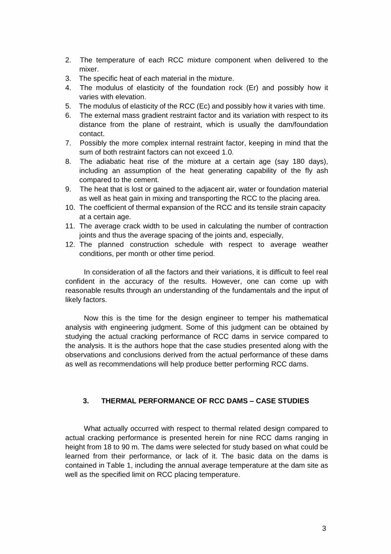
After the dam was completed in August 1987, 13 cracks developed in the
dam at an average spacing of 49 m (see Fig. 1).
Ultimately, the number of cracks increased to 23 with a reduction in the
average spacing to 35 m. In addition to the thermal related contraction, a number
of the cracks may have been initiated by a horizontal downstream movement in
the foundation rock of 10 mm after the reservoir water load was applied to the
dam.
Fig. 1
Aerial view of Upper Stillwater Dam, Utah showing cracking
A finite element computer analysis by the design team predicted cracking,
but indicated the cracks would not penetrate the RCC mass by more than 6 m

6
from the upstream face.
Waterstopped joints at 4.6 m centres were initially proposed, but sealing the
joint in the horizontal slip-formed concrete face was difficult, costly, and would
slow down construction at the site where cold weather limited the effective
construction season to about five months per year. Because the reservoir would
be lowered annually, it was thought any cracks could be repaired from the
upstream face, if needed.
Crack repairs have been made on several occasions with varying results
and costs. The US Bureau of Reclamation first decided to repair the widest crack
(6.6 mm) at Sta. 25+20 (see Fig. 2) and three narrower cracks in 1990 using a
stable hydrophilic polyurethane resin at a cost of about US$600,000. This method
only proved partially effective and not a long term solution.
Portland cement grout was also not really effective due to its lack of
elasticity to accommodate seasonal opening and closing of a crack.
Two more major crack repair related contracts were awarded in 2003. The
first for about US$800,000 was to provide a safe staging area on the left abutment
for the main dam remediation contractor. The second contract for
approximately US$9 million consisted of three different repair methods.
Fig. 2
Leakage in gallery through major crack at Upper Stillwater Dam
Installation of a positive internal membrane was the fix selected for the three
widest cracks, including the one at Sta. 25+20 which was now nearly 30 mm wide
due to erosion from water passing through the crack. Here a corrugated stainless
steel membrane 4.3 m wide was installed to completely cover this as well as two
other major cracks. Vertical 150 mm nominal diameter holes were drilled into the
RCC similar to a secant wall to produce a 114 mm wide slot for insertion of the

7
membrane in 6.1 m lengths. The steel membrane sections were welded together
to produce three effective cutoff membranes varying in depth from 48 to 57 m. Hot
bitumen was poured into the slot to encase the membrane and its enlarged ends
fixed by cement grout to accommodate expansion and contraction of the
membrane.
This contract also consisted of chemically grouting seven cracks with drains
installed behind the remediation grouting. Seven more cracks had only drains
installed downstream of them to relieve water pressures in the dam.
3-Elk Creek Dam. The design by the U.S. Corps of Engineers Portland
District to help control thermal related contraction consisted of placing ten water
stopped transverse joints at a maximum spacing of 90 m across the planned
786 m wide dam. Most of the RCC was to be placed in cool weather where peak
RCC temperatures were reduced by a reported 19°C co mpared to hot summer
placement, which was not allowed. However, due to a rare hot spell in April 1987,
some RCC placement did occur during hot weather. Still the RCC was placed
below the specified limit of 21.1°C. In October 198 7, a court order permanently
stopped all work on the dam with only 25 m of the 76 m high structure completed.
Three uncontrolled cracks occurred later between the widely spaced
transverse joints. The cracks were located (a) near the centre of the depressed
spillway section, (b) adjacent to the reinforced concrete outlet works structure and
(c) at a change in the slope of the foundation rock. All the crack locations are at a
plane of reduced cross section or a potential stress concentration.
4-Hudson River #11 Dam. The design for this dam included PVC membrane
faced precast concrete panels for seepage control, but no transverse joints.
Cooling measures used by the contractor to meet the specified maximum RCC
placing temperature of 18.3°C included sprinkling a ggregate stockpiles, use of
flaked ice in the mix water and limiting RCC placement to nine hours at night.
Still, during June 1993, the noted cooling methods could not keep the RCC
temperature below the specified limit.
The owners then decided to proceed with higher placing temperatures, up to
26.7°C and accept the consequences rather than susp ending RCC placement
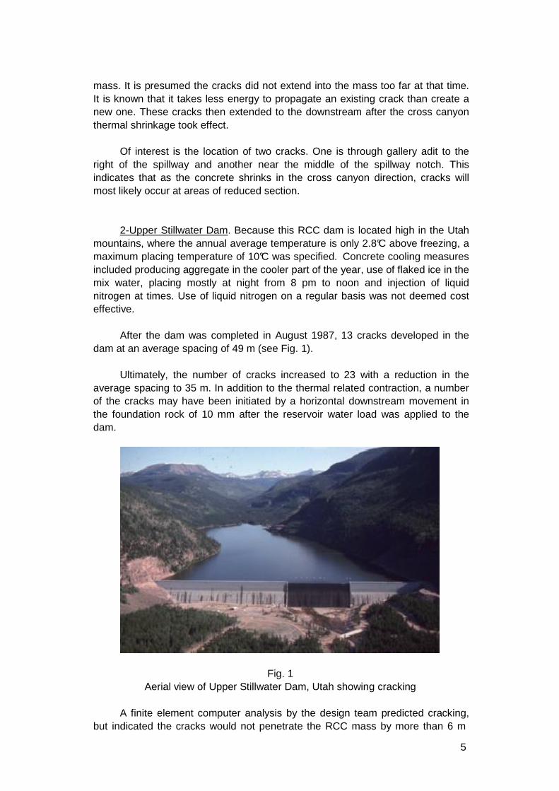
until the cooler time of the year. Except for one major crack, cracking observed on
the downstream face was minor. The single wide crack is located about 0.6m
inside the right end of the spillway and intersects the right gallery adit (see Fig. 3).
Cracking at this location was not surprising as it is where there is a reduction in
cross section due to the adit opening as well as close to a potential stress
concentration where the dam's alignment turns abruptly downstream.
It was concluded by the design engineers that there was no conclusive
evidence that any additional cracking occurred solely due to the increased RCC
placing temperature. The thermal situation was aided somewhat when the
measured peak interior temperature had been reduced by a greater heat loss to
the atmosphere than the 25% loss assumed in the calculations.
8
Fig. 3
Crack at Hudson River No. 11 Dam, Georgia
5-Big Haynes Dam. This RCC dam is unique is that it was designed as
seven separate RCC monoliths due to foundation conditions varying from rock to
compacted soil. Joints that could accommodate movement both horizontally and
vertically separated the monoliths which averaged 53 m in length.
The specified weighted limiting average temperature of 23.3°C over a 24
hour period without the introduction of liquid nitrogen was difficult to meet. This
was mainly because construction delays pushed RCC placement into the hotter
summer months. Prior to the onset of hot weather, the only cooling method used
was the introduction of bagged or block ice into the mix water. A single all-in
gradation aggregate stockpile while produced in cooler weather could not be
further cooled effectively by shading due to the large size of the pile.
Approximately 20% of the RCC required further cooling during hot weather.
Liquid nitrogen was introduced into the first lift each day to help with maintaining
the RCC temperature below the weighted average maximum. Then, more liquid
nitrogen was introduced when the RCC approached the temperature limit. The ice
in the mix water reduced the RCC temperature about 0.6°C and the nitrogen by
about 1.1 to 1.7°C. The cost of cooling in 1996 was about US$5.50/m3 for the
RCC cooled that included the cost of the nitrogen.
Intermediate cracks formed in at least 3 of the monoliths. These cracks were
mainly attributed to settlement of the concrete section on a non-rock foundation.
6-Deep Creek Dam #5D. A Level 1 Corps of Engineers thermal analysis
spaced the transverse joints mainly at 18 m centres for the 226 m long RCC
portion of this composite dam that includes an earthfill portion on the left
abutment.
9
The specification recognized that the average placing temperature in a 24
hour period was more technically correct than a strict maximum RCC placing
temperature. Thus, the RCC placing temperature was allowed to reach 22.8°C for
a period up to 4 hours as long as the weighted average did not exceed 21.1°C.
The design which also included face joints spaced at 4.6 m in the grout
enriched RCC (GERCC) facing effectively controlled thermal related cracking
except for one crack. The crack occurred about 4.6 m from an induced and water
stopped transverse joint close to the right abutment. This uncontrolled crack was
determined to have been caused by a small foundation anomaly that reduced the
relatively narrow section near an area of high foundation restraint.
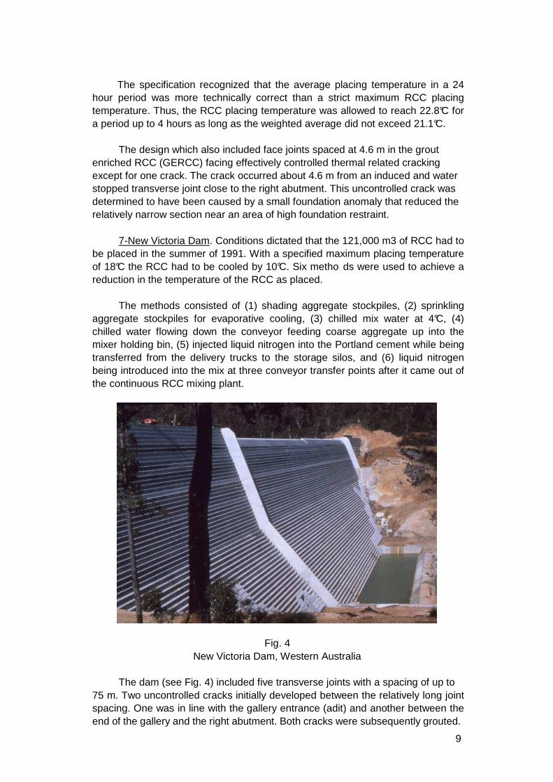
7-New Victoria Dam. Conditions dictated that the 121,000 m3 of RCC had to
be placed in the summer of 1991. With a specified maximum placing temperature
of 18°C the RCC had to be cooled by 10°C. Six metho ds were used to achieve a
reduction in the temperature of the RCC as placed.
The methods consisted of (1) shading aggregate stockpiles, (2) sprinkling
aggregate stockpiles for evaporative cooling, (3) chilled mix water at 4°C, (4)
chilled water flowing down the conveyor feeding coarse aggregate up into the
mixer holding bin, (5) injected liquid nitrogen into the Portland cement while being
transferred from the delivery trucks to the storage silos, and (6) liquid nitrogen
being introduced into the mix at three conveyor transfer points after it came out of
the continuous RCC mixing plant.
Fig. 4
New Victoria Dam, Western Australia
The dam (see Fig. 4) included five transverse joints with a spacing of up to
75 m. Two uncontrolled cracks initially developed between the relatively long joint
spacing. One was in line with the gallery entrance (adit) and another between the
end of the gallery and the right abutment. Both cracks were subsequently grouted.
10
Records from the contractor indicated the actual cost of cooling all the RCC, as
well as 13,000 m3 of conventional concrete, was A$6.80/ m3 or 10.5% additional
cost to the RCC in place.
8-Arriaran Dam. The designers of this unique appearing RCC dam located
in the Basque country of Spain performed an extensive literature search and
complex thermal analysis in two phases to design for the potential thermal
induced cracking in the structure. Based on the analysis, two joints, spaced at
65.7m and then 61.0m starting from the left abutment, were installed. .
Upon completion of the dam in Nov. 1992, two uncontrolled vertical cracks
were detected in the central portion of the dam. One year later, further cross
canyon shortening produced another crack near the middle of the left hand block.
All the cracks were located close to some weakened plane in the body of the dam
where stress concentrations are likely to occur. The locations were near the
gallery adit, conduits encased in conventional concrete and the intersection of the
upper gallery with the abutment.
Conclusions developed by the designers from the actual performance
compared to the thermal analysis indicated (a) the cracks were thermal induced
as expected, originated at the foundation contact and propagated upward (b) the
joints should have been spaced closer together and (c) it is important to simulate
structural irregularities in the finite element model. and locate the contraction
joints near the zones indicated with higher tensile stresses.
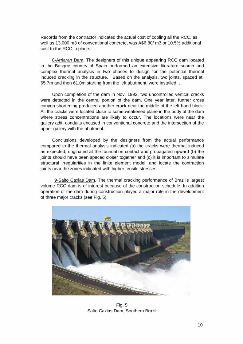
9-Salto Caxias Dam. The thermal cracking performance of Brazil’s largest
volume RCC dam is of interest because of the construction schedule. In addition
operation of the dam during construction played a major role in the development
of three major cracks (see Fig. 5).
Fig. 5
Salto Caxias Dam, Southern Brazil
11
The 1,083 m long dam is divided into three main parts (1) a gated spillway section
atop RCC on the right side, (2) a 280 m long river bed section in the middle and a
non-overflow section at the left abutment.
Transverse joints were installed in the spillway section at 20.5 m spacing.
For the other two RCC sections, full section transverse joints were installed at
40m spacing, with partial transverse joints induced through the section for only the
upstream and downstream thirds, in between the main joints. Only flaked ice in
the mix water was used for cooling the RCC to below a reported 15 deg. C.
Due to the potential for high flows in the Iguacu River during the rainy
season, overtopping the central river bed section was pre-planned. This portion of
the dam was overtopped during construction five times. A maximum overflow of
about 5,000m3/s caused no significant damage. RCC placement on the left
abutment section continued through these overflow events.
By keeping this portion of the dam lower than the remainder of the structure,
the upper portion RCC placement was started during the hot summer weather
eight months after completion of the RCC below. The new RCC was thus placed
on top of an RCC surface that had cooled naturally by losing heat to the
atmosphere as well as by the overflowing water.
The location of three major cracks is of interest. All three cracks are in the
central river bed section where the RCC was placed last. One crack is near the
left end of the section where the foundation rises creating a slightly smaller cross
section. Another crack is in the first block adjacent to the previously placed
spillway section where a stress concentration is likely. The third crack is located
about halfway between the other two cracks and coincident with a partial
transverse joint to relieve an excess cross canyon tensile stress.
These cracks were repaired soon after completion in 1999 with a variety of
materials and mixture proportions. In general, the initial repairs were not
successful in the long term and the owner undertook further repairs in 2006.
A further problem was encountered with some of the partial joints in the left
abutment where the central third of the width of the cross section of the dam was
left uncut, with the expectation that a crack would develop through, propagating
from upstream and downstream to join up as a single crack/joint. In actuality many
did not meet up with the result that a crack propagating from downstream to
upstream, intersected the upstream face about 1-2m away from the waterstop
resulting in an uncontrolled ‘crack/joint’ and consequent leakage
3. SOME OTHER ADVERSE THERMAL EXPERIENCES
The Authors have, over the years, experienced some particular thermal
phenomena which designers need to be conscious of as discussed below:

12
1-Cadiangullong Dam, Australia (43 m high, 110,000 m3 RCC, 380 m long).
The transverse contraction joints (placed typically at 20-30 m spacing - depending
on topographical and geological features) did not all open at the same time. The
first one to open took the majority of the contractions, opening 8 mm with others
opening later about 5 mm and some only 2 mm. Three of the early opening joints
with wide openings showed leaks passing the PVC waterstop, indicative of a tear
occurring through the PVC.
It would appear that joint construction by the usual procedure of cutting and
inserting of a ‘joint inducer’ plate, or PVC sheeting, through the RCC to provide a
plane of reduced tensile resistance is somewhat variable, with result that the
weakest contraction joint opens first, taking up more contraction than those which
open later.
2-Kinta Dam, Malaysia (90 m high, 930,000 m3 RCC). Here transverse joints
were designed to be placed at 30 m centres and the upstream 4 m of RCC cooled
to 20°C, the remainder of the dam being placed un-c ooled, reaching up to 30°C,
all as determined by a detailed thermal stress analysis undertaken using ANSYS.
The analysis showed the critical case was thermal shock cracking of the upstream
face on first filling of the reservoir based on a 9 month RCC placing period. To
prevent cracking the tensile strength of the upstream GERCC facing and adjacent
RCC had to achieve 1.0 MPa at 90 days (see Fig 6). The contractor objected to
any cooling of RCC, volunteering rather to reduce the spacing of the joints to 20
m, which still would not prevent cracking on first filling. His actual RCC placing
time overran that expected during design from 9 to 22 months. When reservoir
impoundment eventually took place, the tensile strength of the RCC facing was
twice that required and consequently the predicted face cracking never occurred!
Fig 6
Kinta Dam, Ipoh Malaysia
A lot of design effort went into the thermal stress analysis based on the best
expectations at that time, but in the end the actual situation proved quite different,
as is often the case.

13
3-Pangue Dam, Chile (120 m high, 640,000 m3 RCC). A detailed thermal
stress analysis determined the transverse joint spacing of 40 m, with the width of
the last monolith block on each abutment being about 45 m (see Fig 7). Some
months after impoundment, an inclined crack developed almost midway along the
last block on the left abutment. The maximum height of the block was 30 m,
reducing to zero. The crack was inclined in towards the abutment and normal to
the axis of the dam. The last block on the opposite abutment had a max height of
70 m, reducing to 6 m but did not crack.
Fig 7
Pangue Dam, Southern Chile
Despite the results of a thermal stress analysis it would seem prudent to
reduce by one-half, the joint spacing for the upper blocks where the height to
block width ratio is significantly different to the remainder of the dam as analysed.
4. MAIN OBSERVATIONS AND CONCLUSIONS
1. Major thermal-related cracks are basically vertical, through the entire dam
section, and may be of sufficient width to pass water at times. Because RCC
dams invariably have a traditional gravity dam shape, these vertical cracks
are not considered detrimental to the structural stability of the dam.
2. Cracks in an RCC gravity dam may not have been caused solely by thermal
induced tensile stresses. In some cases, reservoir induced horizontal
movements in the foundation or differential settlements in a non-rock or low
modulus rock foundation as well as concrete shrinkage due to loss of water
may have contributed to the cracking.
3. All transverse cracks do not initiate at the same time, nor are they of the same
width. While a constant crack width is used in a simplified thermal analysis,
measured crack widths can vary by a factor of more than 4 between the
14
widest and narrowest crack width in a transverse joint. Similar to concrete
pavement joints, the first cracks observed tend to be the widest in the long
run.
4. The most common cause of greater than anticipated cracking than predicted
by a thermal analysis is a delay of construction schedule that pushes RCC
placement into the warmer summer months resulting in a higher peak
temperature in the RCC' mass than used in the analysis.
5. Average crack spacing for stronger RCC tends to be greater than lower
strength concrete due to its increased tensile strain capacity. Because the
total length reduction needs to be accommodated by a lesser number of
cracks, the average width is greater. These wider cracks are a greater
problem if they pass water.
6. The location of uncontrolled cracks tend to be at planes of reduced cross
section or stress concentrations such as:
a. Through the gallery entrance adit.
b. In the centre and at times near the ends of the spillway notch.
c. High in the dam near the abutments where there is greater foundation
restraint together with a reduced section.
d. Protrusions of the foundation rock into the dam.
e. Adjacent to a conduit penetrating the dam, or
f. Near a change in the axis of the dam.
7. Repair of wide uncontrolled cracks can be quite expensive, especially if the
reservoir cannot be completely lowered for repairs. At Upper Stillwater Dam,
the total cost of various methods of crack repair has exceeded $7 million.
8. The cost for providing an equal reduction in RCC placing temperature is not
constant. The use of chilled water or ice in the mixing water provides the
lowest cooling cost per degree. The use of liquid nitrogen is considered
expensive and may not provide sufficient cooling benefit in relation to its cost.
9. Surface cracks due to a high thermal gradient between a hot interior and a
cool surface may not initially penetrate far into the surface. However, they
may turn into full section cracking as it is easier to propagate an existing crack
than initiate a new one.
10. While a complex computer thermal analysis can be quite accurate in
predicting temperatures with time as the RCC is placed layer by layer, they
are less accurate in predicting crack location and width.
5. MAIN RECOMMENDATIONS
1. In order to reasonably control thermal-induced cracking in an RCC dam, the
designer needs to consider both pre-cooling measures for the concrete and
also the installation of transverse contraction joints.

15
2. If the construction schedule will permit, producing aggregate in the winter and
restricting RCC placement to nights and the cooler part of the day or year is
invariably the most effective and least costly temperature control method.
3. The limiting maximum placing temperature for the RCC should consider the
annual average temperature at the site, the function of the dam, and the cost
of extreme cooling measures, if too low an RCC placing limit is specified.
4. Rather than specifying a strict maximum placing temperature for the RCC,
consideration should be given to specifying a limiting average temperature
over a 1 or 3 day period with a higher placing temperature allowed for a short
period of time each day. In this manner, the contractor can better plan his
cooling method and placement schedule with an eye toward cost reduction,
without increasing cracking potential.
5. Cooling should be pre planned by the contractor for the worst case weather
scenario especially with respect to cooling of aggregates. If additional cooling
is required at the last moment, low cost cooling methods may no longer be
available.
6. Transverse joints should include a waterstop and drain, be relatively easy to
install, not affect RCC placement to any great extent and use low cost
materials to produce a weakened plane. Considerable care should be taken
in installing waterstops. There are too many cases in all types of concrete
dams of improperly installed waterstops leading to excessive leakage at the
joint and costly repairs.
7. Transverse joints should be strategically located and need not be spaced
equally across the dam. See Observation/Conclusion #6 for possible location
of transverse joints to better control cracking. Recently, quite a few designs
have used an average spacing of about 20 m.
8. Sealed or waterstopped joints in the facing concrete (where used) should also
be part of the design to control drying shrinkage or initial thermal related
surface cracking.
9. These vertical face joint notches are usually spaced in the range of 3.7 to
4.9 m. Surface cracks will usually initiate in the face joint and could propagate
downstream later. The face joint notches should be either waterstopped or
sealed. At times these will require resealing
10. Crack inducers need not be placed in every lift in the full upstream
downstream direction to be effective. Placing the crack inducer in every other
lift seems to work effectively. Extending the inducer only a partial distance
from both the upstream and downstream faces is not recommended, as it has
been found the upstream – downstream propagation of the cracks do not
actually meet up, with the result that the downstream initiated one is not
sealed by a waterstop. Salto Caxias dam is a good example of this.
11. An old graph showing typical adiabatic heat rise curves for up to 28 days for

16
varying Type I and II Portland cements should not be used. This is because
newer cements produce more early heat than in the past due to finer grinding
and the use of fly ash in the mixture produces a heat peak well past 28 days.
This increased temperature peak may be offset by a heat loss to the
atmosphere and other boundary conditions greater than the 25% assumed by
some designers.
REFERENCES
[1] Hansen, Kenneth D., and Reinhardt, William G., “Roller Compacted
Concrete Dams”, McGraw-Hill, Inc., New York, NY, 298 pp, 1991
[2] Tatro, Stephen and Schrader, Ernest, “Thermal Analysis for RCC - A
Practical Approach”, Roller Compacted Concrete III, ASCE, New York,
NY, 1992, pp. 389-405
[3] Jackson, H.E., “Thermal Cracking in Roller Compacted Concrete of
Galesville Dam, ICOLD Sixteenth Congress, San Francisco, June 1988,
Vol.5 pp. 462-465
[4] Forbes, B.A., Gillon, B.R., and Dunstan, T.G., “Cooling of RCC and
Construction Techniques Adopted for New Victoria Dam, Australia”,
Proceedings of the International Symposium on Roller Compacted
Concrete Dams, Beijing, China, April 1991, pp. 401-408
[5] Hopman, Dennis R., “Lessons Learned From Elk Creek Dam”, Roller
Compacted Concrete II, ASCE, New York, NY, 1992, pp. 162-180
[6] Richardson, Alan T., “Performance of Upper Stillwater Dam”, Roller
Compacted Concrete III, ASCE, New York, NY, 1992, pp. 148-161
[7] Aquirre Sanchez, E. and Villarroel Gonzales-Ellpe, J.M. “Thermal
Analysis and Behavior of the Arriaran Dam”, Proceedings of the
International Symposium on Roller Compacted Concrete Dams,
Santander, Spain, 1995, pp. 1067-1061.
[8] Soares, M.A., Levis, P., Seara, R.W., Ferreira, E.S. and Terres, J.F.,
“Seepage and Treatment of Cracks in Salto Caxias Dam”, Proceedings of
the Fourth International Symposium on Roller Compacted Concrete
(RCC) Dams, Madrid, Spain, November 2003, pp. 1185-1191
[9] Barrett, Bruce and Ringel, Jan, “Upper Stillwater Crack Repair”,
Proceedings of the Association of Dam Safety Officials (ASDSO) 2006
Annual Conference, Boston, Massachusetts, September 2006
[10] Fitzgerald, Thomas, Hansen, Kenneth D., and Marshall, Tillman, “Hot
Dam! Mass Concrete – Expected vs. Actual Performance”, Proceedings
of the ASDSO. 2011 Annual Conference, Washington, D.C.