Embed Size (px)
DESCRIPTION
G MANIKANDAN M ANANDA RAO * Professor Professor and Principal SS Institute of Technology SS Institute of Technology Dundigal, Hyderabad Dundigal, Hyderabad Andhra Pradesh, India Andhra Pradesh, India [email protected] profanandarao @yahoo.com +91 9618190732 +91 9966049083 G MANIKANDAN et al. / (IJAEST) INTERNATIONAL JOURNAL OF ADVANCED ENGINEERING SCIENCES AND TECHNOLOGIES Vol No. 4, Issue No. 1, 053 - 068 ISSN: 2230-7818 @ 2011 http://www.ijaest.iserp.org. All rights Reserved. Page 53
Citation preview
Aerofoil Flutter Analysis, Simulation and
Optimization
G MANIKANDAN M ANANDA RAO*
Professor Professor and Principal SS Institute of Technology SS Institute of Technology Dundigal, Hyderabad Dundigal, Hyderabad Andhra Pradesh, India Andhra Pradesh, India [email protected] profanandarao @yahoo.com +91 9618190732 +91 9966049083
IJAEST
G MANIKANDAN et al. / (IJAEST) INTERNATIONAL JOURNAL OF ADVANCED ENGINEERING SCIENCES AND TECHNOLOGIES Vol No. 4, Issue No. 1, 053 - 068
ISSN: 2230-7818 @ 2011 http://www.ijaest.iserp.org. All rights Reserved. Page 53

Abstract: Two degrees of freedom flutter
mounting system model has been developed
by finite element method. Bending and
Torsional natural frequencies were
obtained by modal analysis and compared
with the experimental analysis. The
numerical results were in good agreement
with experimental investigation. Aerofoil
shape has been optimized by normal to
reference line method and aerodynamic
characteristics were derived. Optimized
aerofoil shape obtained by changing the
location of maximum thickness has been
used for the development of ribs and aero
elastically similar aluminium wing models
have been fabricated. Effect of maximum
thickness location of aerofoil with C, I and
Z section spar on flutter speed has been
investigated and compared with the base
line NACA 0012 aerofoil.
Nomenclature
L = Lift R = Dimensionless radius of gyration of the wing about elastic axis S = Dimensionless complex eigenvalue V = Dimensionless free stream speed of air b = Semi chord e, a = Dimensionless parameter (-1≤ e, a ≤ 1) m = Mass per unit span u = Plunge displacement Ө = Pitching displacement α = Angle of Attack σ = Ratio of uncoupled bending to torsional frequencies µ = Mass ratio Ic = Moment of Inertia about center of mass Ip = Moment of Inertia about the elastic axis Ku = Spring constant of Helical spring KӨ = Spring constant of Spiral spring M1/4 = Moment about ¼ chord Г1, Г2 = Real part of complex conjugate roots
Ω1, Ω2 = Imaginary part of complex conjugate roots Ṉ = Maximum amplitude of pitching displacement Ѡu = Uncoupled bending natural frequency ѠӨ = Uncoupled torsion natural frequency ü = Plunge acceleration ӫ = Pitch rotational acceleration
I Introduction
Flutter, an unstable oscillatory aerodynamic condition with high frequency and large amplitude ensuing from fluid structure interaction is of precise interest for many aero elastic researchers. This demon results in a catastrophic failure of structure rapidly. Therefore, there is an immense requirement of predicting the flutter speed accurately considering the various uncertain conditions obviously. The general theory of aero elastic instability and the crux of elementary mechanism of flutter have been explained profoundly by many earlier researchers [1-3]. Structural and aerodynamic uncertainties are inevitable in the design stage even though pronounced care is taken to alleviate the inaccuracies. Wind tunnel tests must be conducted to determine and correct the uncertainties in flutter analysis. NACA 0012 benchmark model experimental flutter analysis with unsteady pressure distributions were conducted to ensure correct prediction of flutter speed [4]. It is imperative to design flutter mounting system for mounting the wing model. A Two Degree of Freedom Flutter Mount System with Low Damping for Testing Rigid Wings at Different Angles of Attack was developed [5]. The benchmark active control technology wind-tunnel model for active flutter control applications was designed [6]. Experimental methods were developed for the Flutter Analysis of Complex Airplanes
IJAEST
G MANIKANDAN et al. / (IJAEST) INTERNATIONAL JOURNAL OF ADVANCED ENGINEERING SCIENCES AND TECHNOLOGIES Vol No. 4, Issue No. 1, 053 - 068
ISSN: 2230-7818 @ 2011 http://www.ijaest.iserp.org. All rights Reserved. Page 54

[7]. A new Flutter Testing Technique using a Towed Dynamic Airplane Model equipped with an Automatic Stabilizing System was developed [8]. Various analytical and numerical approximation methods were developed for flutter analysis. Navier-Stokes equations were used by many researchers to design aerodynamic models for the computation of wing flutter [9]. For calculating unsteady transonic aerodynamic flow characteristics, Euler equations with small perturbation and approximate boundary conditions were utilized for the computation of flutter [10 - 12] In this paper, two degrees of freedom flutter mounting system model has been developed by finite element method. Bending and Torsional natural frequencies were obtained by modal analysis and compared with the experimental analysis. Aerofoil shape has been optimized by normal to reference line method and aerodynamic characteristics were derived. Optimized aerofoil shape obtained by changing the location of maximum thickness has been used for the development of ribs and Composite material wings have been fabricated. Effect of maximum thickness location of aerofoil on flutter speed has been investigated and compared with the base line NACA 0012 aerofoil.
II Flutter Speed Formulation
The aerodynamic characteristics have been derived by vortex panel method for the optimized aerofoils obtained by normal to reference line method developed by the author by changing the maximum thickness location of aerofoil. The two degrees of freedom flutter problem has been solved by considering the dynamic equation of motion of the flutter system given by
m (ü + b (e-a) ӫ) + Ku u = - L ---- (1) Ip ӫ + b m (e-a) ü + KӨ Ө = M1/4 + b(1/4+a)L ----- (2) Using vortex panel method, lift has been calculated and M1/4 = 0 was assumed. The uncoupled natural frequencies at zero airspeed is defined by
Ѡu = √ √
------(3)
ѠӨ = √ √
------ (4)
The equation of motion are then simplified into
[ ( ( )) ( )
( ) ( )( )
]
------ (5) For nontrivial solution, the determinant of the co-efficient matrix was set equal to zero and two complex conjugate pairs of roots have been calculated by S1 = (Г1 i Ω1) / ѠӨ ………. (6) S2 = (Г2 i Ω2) / ѠӨ ………. (7)
III Flutter Mounting System Design and
Analysis.
Flutter mounting system provides two degrees of freedom dynamic system for fixing wing for flutter test in the wind tunnel. NACA 0012 aerofoil profile has been used for the fabrication of four aluminium ribs with 1 mm web and 2 mm flange, one each at wing root & tip chord and two at wing mid chord. Aluminium I section spar and 1.2 mm thick skin has been used for the fabrication of wing model. Four stiffeners of 2mm thickness, two on upper and two on lower side of wing has been used to strengthen the wing skin. The span of the wing is 24 cm and the chord is 15 cm. The root chord is firmly fitted to the rectangular base plate and is bolted to movable circular plate of diameter 30 cm. The fixed plate is attached to the movable plate by means of four 10 mm circular cross section rods. The
IJAEST
G MANIKANDAN et al. / (IJAEST) INTERNATIONAL JOURNAL OF ADVANCED ENGINEERING SCIENCES AND TECHNOLOGIES Vol No. 4, Issue No. 1, 053 - 068
ISSN: 2230-7818 @ 2011 http://www.ijaest.iserp.org. All rights Reserved. Page 55

rods are attached to both the plates rigidly by means of double locked nuts. A rectangular drag strut made of steel is attached to the base plate of wing as shown in the figure.
Figure 1: Mounting System for Flutter
Analysis.
The bending and torsional natural frequencies of the model has been calculated by using bending and torsional theory and compared with Finite element modal analysis. The mount system was meshed with 3d solid element and beam element. A total of 8468 elements with 17159 nodes have been created for the development of finite element mount system as shown in figure.
Figure 2: Finite element model of Flutter
Mount System.
The first mode bending and torsional natural frequencies obtained from finite
element analysis are compared with the bending and torsional theoretical analysis as shown in table 1. Table 1: First Mode Bending and
Torsional Natural Frequencies.
The first and second mode bending and torsional mode shapes of the mount system are shown in figure 3 and 6.
Figure 3: First Mode Bending Mode
Shape of Flutter Mount System.
Figure 4: First Mode Torsional Mode
Shape of Flutter Mount System.
IJAEST
G MANIKANDAN et al. / (IJAEST) INTERNATIONAL JOURNAL OF ADVANCED ENGINEERING SCIENCES AND TECHNOLOGIES Vol No. 4, Issue No. 1, 053 - 068
ISSN: 2230-7818 @ 2011 http://www.ijaest.iserp.org. All rights Reserved. Page 56

Figure 5: Second Mode Bending Mode
Shape of Flutter Mount System
Figure 6: Second Mode Torsional Mode
Shape of Flutter Mount System
IV Results and Discussions
Optimized seven aerofoil profiles (set 1 to set 7) and NACA 0012 (set 8) has been used for the fabrication of wing for the experimental flutter analysis in the subsonic wind tunnel operated at a maximum speed of 35 m/sec. The flutter speeds obtained for wings with C section spar are presented in the table 2.
Table 2: Flutter Speed of Ten Wing
Models (C Section)
Graph 1 to 16 illustrates the mode frequency and mode damping with respect to dimensionless free stream velocity for the eight wing flutter model with C section spar. It has been investigated that a slight variation of flutter speed occurs due to the change in location of maximum thickness. It has been found that the set 1 aerofoil flutter speed proved to be better than set 8 (NACA 0012).
Graph 1: Modal Frequency vs. Dimension
less Free Stream Speed of Air for set
1(0012 C Sec)
IJAEST
G MANIKANDAN et al. / (IJAEST) INTERNATIONAL JOURNAL OF ADVANCED ENGINEERING SCIENCES AND TECHNOLOGIES Vol No. 4, Issue No. 1, 053 - 068
ISSN: 2230-7818 @ 2011 http://www.ijaest.iserp.org. All rights Reserved. Page 57

Graph 2: Modal Damping vs. Dimension
less Free Stream Speed of Air for set
1(0012 C Sec)
Graph 3: Modal Frequency vs. Dimension
less Free Stream Speed of Air for set
2(0012 C Sec)
Graph 4: Modal Damping vs. Dimension
less Free Stream Speed of Air for set
2(0012 C Sec)
Graph 5: Modal Frequency vs.
Dimension less Free Stream Speed of Air
for set 3(0012 C Sec)
Graph 6: Modal Damping vs. Dimension
less Free Stream Speed of Air for set
3(0012 C Sec)
Graph 7: Modal Frequency vs.
Dimension less Free Stream Speed of Air
for set 4(0012 C Sec)
IJAEST
G MANIKANDAN et al. / (IJAEST) INTERNATIONAL JOURNAL OF ADVANCED ENGINEERING SCIENCES AND TECHNOLOGIES Vol No. 4, Issue No. 1, 053 - 068
ISSN: 2230-7818 @ 2011 http://www.ijaest.iserp.org. All rights Reserved. Page 58

Graph 8: Modal Damping vs. Dimension
less Free Stream Speed of Air for set 4 ( C
Sec)
Graph 9: Modal Frequency vs.
Dimension less Free Stream Speed of Air
for set 5(0012 C Sec)
Graph 10: Modal Damping vs. Dimension
less Free Stream Speed of Air for set 5(C
Sec)
Graph 11: Modal Frequency vs.
Dimension less Free Stream Speed of Air
for set 6(0012 C Sec)
Graph 12: Modal Damping vs. Dimension
less Free Stream Speed of Air for set
6(0012 C Sec)
Graph 13: Modal Frequency vs.
Dimension less Free Stream Speed of Air
for set 7(0012 C Sec)
IJAEST
G MANIKANDAN et al. / (IJAEST) INTERNATIONAL JOURNAL OF ADVANCED ENGINEERING SCIENCES AND TECHNOLOGIES Vol No. 4, Issue No. 1, 053 - 068
ISSN: 2230-7818 @ 2011 http://www.ijaest.iserp.org. All rights Reserved. Page 59

Graph 14: Modal Damping vs. Dimension
less Free Stream Speed of Air for set
7(0012 C Sec)
Graph 15: Modal Frequency vs.
Dimension less Free Stream Speed of Air
for set 8(0012 C Sec)
Graph 16: Modal Damping vs. Dimension
less Free Stream Speed of Air for set
8(0012 C Sec)
The flutter speeds obtained for wings with I section spar are presented in the table
2. It has been investigated that the flutter speed increased when compared with C section spar wings with the change in maximum location of aerofoil.
Table 3: Flutter Speed of Ten Wing
Models (I Section)
Graph 17 to 32 represent the mode frequency and mode damping with respect to dimensionless free stream velocity for the eight wings flutter model with I section spar. It has been investigated that a slight variation of flutter speeds due to the change in location of maximum thickness and shape of spar. It has been observed that set 1 flutter speed was proved to be better than NACA 0012.
Graph 17: Modal Frequency vs.
Dimension less Free Stream Speed of Air
for set 1(0012 I Sec)
IJAEST
G MANIKANDAN et al. / (IJAEST) INTERNATIONAL JOURNAL OF ADVANCED ENGINEERING SCIENCES AND TECHNOLOGIES Vol No. 4, Issue No. 1, 053 - 068
ISSN: 2230-7818 @ 2011 http://www.ijaest.iserp.org. All rights Reserved. Page 60

Graph 18: Modal Damping vs. Dimension
less Free Stream Speed of Air for set
1(0012 C Sec)
Graph 19: Modal Frequency vs.
Dimension less Free Stream Speed of Air
for set 2(0012 I Sec)
Graph 20: Modal Damping vs. Dimension
less Free Stream Speed of Air for set
2(0012 C Sec)
Graph 21: Modal Frequency vs.
Dimension less Free Stream Speed of Air
for set 3(0012 I Sec)
Graph 22: Modal Damping vs. Dimension
less Free Stream Speed of Air for set
3(0012 C Sec)
Graph 23: Modal Frequency vs.
Dimension less Free Stream Speed of Air
for set 4(0012 I Sec)
IJAEST
G MANIKANDAN et al. / (IJAEST) INTERNATIONAL JOURNAL OF ADVANCED ENGINEERING SCIENCES AND TECHNOLOGIES Vol No. 4, Issue No. 1, 053 - 068
ISSN: 2230-7818 @ 2011 http://www.ijaest.iserp.org. All rights Reserved. Page 61
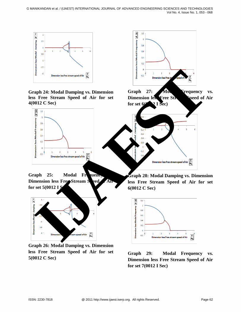
Graph 24: Modal Damping vs. Dimension
less Free Stream Speed of Air for set
4(0012 C Sec)
Graph 25: Modal Frequency vs.
Dimension less Free Stream Speed of Air
for set 5(0012 I Sec)
Graph 26: Modal Damping vs. Dimension
less Free Stream Speed of Air for set
5(0012 C Sec)
Graph 27: Modal Frequency vs.
Dimension less Free Stream Speed of Air
for set 6(0012 I Sec)
Graph 28: Modal Damping vs. Dimension
less Free Stream Speed of Air for set
6(0012 C Sec)
Graph 29: Modal Frequency vs.
Dimension less Free Stream Speed of Air
for set 7(0012 I Sec)
IJAEST
G MANIKANDAN et al. / (IJAEST) INTERNATIONAL JOURNAL OF ADVANCED ENGINEERING SCIENCES AND TECHNOLOGIES Vol No. 4, Issue No. 1, 053 - 068
ISSN: 2230-7818 @ 2011 http://www.ijaest.iserp.org. All rights Reserved. Page 62

Graph 30: Modal Damping vs. Dimension
less Free Stream Speed of Air for set
7(0012 C Sec)
Graph 31: Modal Frequency vs.
Dimension less Free Stream Speed of Air
for set 8(0012 I Sec)
Graph 32: Modal Damping vs. Dimension
less Free Stream Speed of Air for set
8(0012 C Sec)
The flutter speeds obtained for wings with Z section spar are presented in the table 4. It has been investigated that the flutter speed has very less effect when compared with C section spar wings with the change in maximum location of aerofoil. It has been observed that set 1 aerofoil flutter speed was better than NACA 0012. Table 4: Flutter Speed of Ten Wing
Models (Z Section)
Graph 33 to 48 illustrates the mode frequency and mode damping with respect to dimensionless free stream velocity for the ten wings flutter model with Z section spar. It has been investigated that a very less variation of flutter speeds due to the change in location of maximum thickness and shape of spar.
Graph 33: Modal Frequency vs.
Dimension less Free Stream Speed of Air
for set 1(0012 Z Sec)
IJAEST
G MANIKANDAN et al. / (IJAEST) INTERNATIONAL JOURNAL OF ADVANCED ENGINEERING SCIENCES AND TECHNOLOGIES Vol No. 4, Issue No. 1, 053 - 068
ISSN: 2230-7818 @ 2011 http://www.ijaest.iserp.org. All rights Reserved. Page 63

Graph 34: Modal Damping vs. Dimension
less Free Stream Speed of Air for set
1(0012 Z Sec)
Graph 35: Modal Frequency vs.
Dimension less Free Stream Speed of Air
for set 2(0012 Z Sec)
Graph 36: Modal Damping vs. Dimension
less Free Stream Speed of Air for set
2(0012 Z Sec)
Graph 37: Modal Frequency vs.
Dimension less Free Stream Speed of Air
for set 3(0012 Z Sec)
Graph 38: Modal Damping vs. Dimension
less Free Stream Speed of Air for set
3(0012 Z Sec)
Graph 39: Modal Frequency vs.
Dimension less Free Stream Speed of Air
for set 4(0012 Z Sec)
IJAEST
G MANIKANDAN et al. / (IJAEST) INTERNATIONAL JOURNAL OF ADVANCED ENGINEERING SCIENCES AND TECHNOLOGIES Vol No. 4, Issue No. 1, 053 - 068
ISSN: 2230-7818 @ 2011 http://www.ijaest.iserp.org. All rights Reserved. Page 64
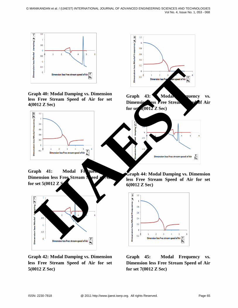
Graph 40: Modal Damping vs. Dimension
less Free Stream Speed of Air for set
4(0012 Z Sec)
Graph 41: Modal Frequency vs.
Dimension less Free Stream Speed of Air
for set 5(0012 Z Sec)
Graph 42: Modal Damping vs. Dimension
less Free Stream Speed of Air for set
5(0012 Z Sec)
Graph 43: Modal Frequency vs.
Dimension less Free Stream Speed of Air
for set 6(0012 Z Sec)
Graph 44: Modal Damping vs. Dimension
less Free Stream Speed of Air for set
6(0012 Z Sec)
Graph 45: Modal Frequency vs.
Dimension less Free Stream Speed of Air
for set 7(0012 Z Sec)
IJAEST
G MANIKANDAN et al. / (IJAEST) INTERNATIONAL JOURNAL OF ADVANCED ENGINEERING SCIENCES AND TECHNOLOGIES Vol No. 4, Issue No. 1, 053 - 068
ISSN: 2230-7818 @ 2011 http://www.ijaest.iserp.org. All rights Reserved. Page 65

Graph 46: Modal Damping vs. Dimension
less Free Stream Speed of Air for set
7(0012 Z Sec)
Graph 47: Modal Frequency vs.
Dimension less Free Stream Speed of Air
for set 8(0012 Z Sec)
Graph 48: Modal Damping vs. Dimension
less Free Stream Speed of Air for set
8(0012 Z Sec)
V Conclusions
Mounting System for Flutter Analysis has been designed and fabricated for wind tunnel testing. Finite element mounting system model has been developed. NACA 0012 aerofoil profile was used as a baseline aerofoil and eight new optimized aerofoil profiles has been developed by changing the location of maximum thickness for the fabrication of wing models and flutter analysis. First and second mode natural frequencies of finite element model was compared with the wind tunnel testing models and found to be in good agreement. Theoretical flutter analysis using P method has been carried out. Wind tunnel flutter analysis results have been compared with theoretical results and good agreement with the theoretical analysis was established. The set 1 model flutter speed was 2 % more than the NACA 0012 model.
References
[1] Theodorsen T, “General Theory of Aerodynamic Instability and the Mechanism of Flutter”, NACA Report No. 496, pp.413-433, 1934 [2] Pines, S., “An Elementary Explanation of the Flutter Mechanism”, Proceedings of the National Specialists Meeting on Dynamics and Aero elasticity, Institute of the Aeronautical Sciences, Ft. Worth, TX, pp. 52-58, November. 1958. [3] Bisplinghoff R. L, Ashley H, and Halfman R. L, “Aero elasticity”, Addison-Wesley Pub. Co., Inc., pp. 791-800, 1935. [4] Rivera J A, “NACA 0012 benchmark model experimental flutter results with unsteady pressure distributions”, NASA TM-107581, 1992.
IJAEST
G MANIKANDAN et al. / (IJAEST) INTERNATIONAL JOURNAL OF ADVANCED ENGINEERING SCIENCES AND TECHNOLOGIES Vol No. 4, Issue No. 1, 053 - 068
ISSN: 2230-7818 @ 2011 http://www.ijaest.iserp.org. All rights Reserved. Page 66

[5] Farmer, M., “A Two Degree of Freedom Flutter Mount System with Low Damping for Testing Rigid Wings at Different Angles of Attack”, NASA TM 83302, National Aeronautics and Space Administration, Hampton Virginia, April 1982. [6] Waszak, M.R, “Modeling the benchmark active control technology wind-tunnel model for active control design applications”, NASA TP-1998-206270, 1998 [7] Kinnaman, E. B “Flutter Analysis of Complex Airplanes by Experimental Methods”, Journal of Aeronautical Sciences, Vol. 19, No. 9, September 1952. [8] Schneider, W. C. “Development of a New Flutter Testing Technique Using a Towed Dynamic Airplane Model Equipped With an Automatic Stabilizing System”, NACA RM L34L23, 1954. [9] Lee-Rausch E M and Batina J T, “Wing flutter computations using an aerodynamic model based on the Navier-Stokes equations”, Journal of Aircraft, Vol.33, No. 6, pp. 1139-1147, 1996. [10] Gao C, Luo S and Liu F, “Calculation of unsteady transonic flow by an Euler method with small perturbation boundary conditions”, AIAA 2003-1267, 2003. [11] Gao C, Luo S, Liu F and Schuster D M, “Calculation of airfoil flutter by an Euler method with approximate boundary conditions”, AIAA 2003-3830, 2003. [12] Bendiksen O. O and Kousen K A, “Transonic flutter analysis using the Euler equation”, AIAA Paper 1987-0911, 1987.
G. Manikandan was born on 12th January 1969 from the famous big temple city Thanjavur, Tamil Nadu. He obtained his Engineering Graduation (Mech) in the
year 1994 from Institution of Engineers (India), Calcutta and M.Tech (CAD/CAM) in the year 2002 from JNTU, Hyderabad. He put up 16 years of colorful service in Indian Air Force. In his credit, he overhauled 365 Rolls Royce Viper Turbojet Engine fitted on Kiran Aircraft and Carried out Structural Repairs and maintenance of Cheetah and Chetak helicopters and Kiran aircraft. He was team leader for several Structural re-fabrications of Ardhra and Rohini Gliders. He developed number of Un-manned Aerial Vehicles (UAV). Presently, his contributions are in the area of aerofoil shape optimization and flutter analysis. He was awarded best in trade and all-rounder for Kiran Aircraft in the year 2000.
M. Ananda Rao obtained B.E (Mech) in 1968, M.Tech (Machine Design) in 1970 and M.Tech (Industrial Engg) in 1984. He was awarded PhD from IIT, Madras in the area of
“Machine Dynamics” in the year 1987. He worked over 33 years in Andhra University at various capacities. He worked in the Link Interchange Program with UK Universities for about 03 years sponsored by British Council and Government of India. He published more than 200 papers in International Journals and more than 50 papers in International and National Conferences. He was awarded three times “The Best Researcher Award” in the year
IJAEST
G MANIKANDAN et al. / (IJAEST) INTERNATIONAL JOURNAL OF ADVANCED ENGINEERING SCIENCES AND TECHNOLOGIES Vol No. 4, Issue No. 1, 053 - 068
ISSN: 2230-7818 @ 2011 http://www.ijaest.iserp.org. All rights Reserved. Page 67

1992, 1999 and 2001. He worked as a technical adviser for Altair Company for the development of software in the domain of solvers. He is one of the renowned researchers in the area of Vibration and Condition Monitoring in the World. He was the nucleus in the starting of Condition Monitoring Society of India.
IJAEST
G MANIKANDAN et al. / (IJAEST) INTERNATIONAL JOURNAL OF ADVANCED ENGINEERING SCIENCES AND TECHNOLOGIES Vol No. 4, Issue No. 1, 053 - 068
ISSN: 2230-7818 @ 2011 http://www.ijaest.iserp.org. All rights Reserved. Page 68