Embed Size (px)
Citation preview

operating manual & parts list 82061B, 82062B, 82071B, 82081B & 82101A
6″, 7″, 8″ & 10″
BENCH GRINDER
Read carefully and follow all safety rules and operating instructions before first use of this product.
25139.19-0407

DESCRIPTION
Palmgren Bench Grinders are equipped with a totally enclosed ballbearing motor. Armature assembly is dynamically balanced forsmooth operation. Motor housing is compact so long pieces ofwork can press against both wheels without touching the motorframe. Removable wheel guards allow for easy changing of wheels.Two-way tool rests are adjustable for wheel wear and angle grind-ing. Grinders come complete with spark guards, safety eyeshieldsand dust collection hose. (Dust Collection hose not included with82061A).
UNPACKING
Check for shipping damage. If damage has occurred, a claim mustbe filed with the carrier immediately. Check for completeness.Immediately report missing parts to dealer.
To be certain the grinding wheels have not been damaged in ship-ment, strike the edges slightly with a metal object. A ringing soundindicates a good wheel, but a dull noise may signal a fracture.
WARNING: If you suspect a wheel of being fractured, replace itimmediately. Fractured wheels may shatter, cuasing serious injury.
SPECIFICATIONS
82061B & 82062B-6” Bench Grinder
Horsepower . . . . . . . . . . . . . . . . . . . . . . . . . . . . . . . . . . . . . . . . . . . . . . . . . . . .1/3
Voltage . . . . . . . . . . . . . . . . . . . . . . . . . . . . . . . . . . . . . . . . . . . . . . . . . .120/240Amperes . . . . . . . . . . . . . . . . . . . . . . . . . . . . . . . . . . . . . . . . . . . . . . . . .3.5/1.75Hertz . . . . . . . . . . . . . . . . . . . . . . . . . . . . . . . . . . . . . . . . . . . . . . . . . . . . . . . . . .60Phase . . . . . . . . . . . . . . . . . . . . . . . . . . . . . . . . . . . . . . . . . . . . . . . . . . . . . .SingleRPM . . . . . . . . . . . . . . . . . . . . . . . . . . . . . . . . . . . . . . . . . . . . . . . . . . . . . . . . .3450Rotation (viewed from left side) . . . . . . . . . . . . . . . . . . . . . . . . .ClockwiseWheel diameter . . . . . . . . . . . . . . . . . . . . . . . . . . . . . . . . . . . . . . . . . . . . . . . .6”Wheel bore . . . . . . . . . . . . . . . . . . . . . . . . . . . . . . . . . . . . . . . . . . . . . . . . . . . .1/2”
82071B-7” Bench Grinder
Horsepower . . . . . . . . . . . . . . . . . . . . . . . . . . . . . . . . . . . . . . . . . . . . . . . . . . . .1/2
Voltage . . . . . . . . . . . . . . . . . . . . . . . . . . . . . . . . . . . . . . . . . . . . . . . . . .120/240Amperes . . . . . . . . . . . . . . . . . . . . . . . . . . . . . . . . . . . . . . . . . . . . . . . . . .5.0/2.5Hertz . . . . . . . . . . . . . . . . . . . . . . . . . . . . . . . . . . . . . . . . . . . . . . . . . . . . . . . . . .60Phase . . . . . . . . . . . . . . . . . . . . . . . . . . . . . . . . . . . . . . . . . . . . . . . . . . . . . .SingleRPM . . . . . . . . . . . . . . . . . . . . . . . . . . . . . . . . . . . . . . . . . . . . . . . . . . . . . . . . .3450Rotation (viewed from left side) . . . . . . . . . . . . . . . . . . . . . . . . .ClockwiseWheel diameter . . . . . . . . . . . . . . . . . . . . . . . . . . . . . . . . . . . . . . . . . . . . . . . .7”Wheel bore . . . . . . . . . . . . . . . . . . . . . . . . . . . . . . . . . . . . . . . . . . . . . . . . . . . .5/8”
82081B-8” Bench Grinder
Horsepower . . . . . . . . . . . . . . . . . . . . . . . . . . . . . . . . . . . . . . . . . . . . . . . . . . . .3/4
Voltage . . . . . . . . . . . . . . . . . . . . . . . . . . . . . . . . . . . . . . . . . . . . . . . . . .120/240Amperes . . . . . . . . . . . . . . . . . . . . . . . . . . . . . . . . . . . . . . . . . . . . . . . . . .7.0/3.5Hertz . . . . . . . . . . . . . . . . . . . . . . . . . . . . . . . . . . . . . . . . . . . . . . . . . . . . . . . . . .60Phase . . . . . . . . . . . . . . . . . . . . . . . . . . . . . . . . . . . . . . . . . . . . . . . . . . . . . .SingleRPM . . . . . . . . . . . . . . . . . . . . . . . . . . . . . . . . . . . . . . . . . . . . . . . . . . . . . . . . .3450Rotation (viewed from left side) . . . . . . . . . . . . . . . . . . . . . . . . .ClockwiseWheel diameter . . . . . . . . . . . . . . . . . . . . . . . . . . . . . . . . . . . . . . . . . . . . . . . .8”Wheel bore . . . . . . . . . . . . . . . . . . . . . . . . . . . . . . . . . . . . . . . . . . . . . . . . . . . .5/8”
82101A-10” Bench Grinder
Horsepower . . . . . . . . . . . . . . . . . . . . . . . . . . . . . . . . . . . . . . . . . . . . . . . . . . . . .1Voltage . . . . . . . . . . . . . . . . . . . . . . . . . . . . . . . . . . . . . . . . . . . . . . . . . .120/240Amperes . . . . . . . . . . . . . . . . . . . . . . . . . . . . . . . . . . . . . . . . . . . . . . . . .10.0/5.0Hertz . . . . . . . . . . . . . . . . . . . . . . . . . . . . . . . . . . . . . . . . . . . . . . . . . . . . . . . . . .60
Phase . . . . . . . . . . . . . . . . . . . . . . . . . . . . . . . . . . . . . . . . . . . . . . . . . . . . . .SingleRPM . . . . . . . . . . . . . . . . . . . . . . . . . . . . . . . . . . . . . . . . . . . . . . . . . . . . . . . . .1725Rotation (viewed from left side) . . . . . . . . . . . . . . . . . . . . . . . . .ClockwiseWheel diameter . . . . . . . . . . . . . . . . . . . . . . . . . . . . . . . . . . . . . . . . . . . . . . .10”Wheel bore . . . . . . . . . . . . . . . . . . . . . . . . . . . . . . . . . . . . . . . . . . . . . . . . . . . . .1”
SAFETY RULES
WARNING: For your own safety, read operating instructions man-ual before operating tool.
BE PREPARED FOR JOB• Wear proper apparel. Do not wear loose clothing, gloves, neck-
ties, rings, bracelets or other jewelry which may get caught inmoving parts of machine.
• Wear protective hair covering to contain long hair.
• Wear safety shoes with non-slip soles.
• Wear safety glasses complying with United States ANSI Z87.1.Everyday glasses have only impact resistant lenses. They areNOT safety glasses.
• Wear face mask or dust mask if operation is dusty.
• Be alert and think clearly. Never operate power tools whentired, intoxicated or when taking medications that causedrowsiness.
PREPARE WORK AREA FOR JOB• Keep work area clean. Cluttered work areas and work benches
invite accidents.
• Do not use power tools in dangerous environments. Do not usepower tools in damp or wet locations. Do not expose powertools to rain.
• Work area should be properly lighted.
• Proper electrical plug should be plugged directly into properlygrounded, three-prong receptacle.
• Extension cords should have a grounding prong and the threewires of the extension cord should be of the correct gauge.
• Keep visitors at a safe distance from work area.
• Keep children out of the workplace. Make workshop childproof.Use padlocks, master switches or remove switch keys to pre-vent any unintentional use of power tools.
TOOL SHOULD BE MAINTAINED• Always unplug tool prior to inspection.
• Consult manual for specific maintaining and adjusting proce-dures.
• Keep tool clean for safest operation.
• Remove adjusting tools. Form habit of checking to see thatadjusting tools are removed before turning machine on.
• Keep all parts in working order. Check to determine that theguard or other parts will operate properly and perform theirintended function.
• Check for damaged parts. Check for alignment of moving parts,binding of moving parts, breakage of parts, mounting and anyother condition that may affect a tool’s operation.
• A guard or other part that is damaged should be properlyrepaired or replaced. Do not perform makeshift repairs. (Usethe parts list to order replacement parts.)
KNOW HOW TO USE TOOL• Use right tool for job. Do not force tool or attachment to do a
job for which it was not designed.
• Disconnect tool from power when changing accessories suchas grinding wheels, buffing wheels and the like.
2
Palmgren Operating Manual & Parts List 82061B, 82062B, 82071B, 82081B & 82101A

3
SAFETY RULES (CONTINUED)• Avoid accidental start-up. Make sure that the switch is in the off
position before plugging in.
• Do not force tool. It will work most efficiently at the rate forwhich it was designed.
• Keep hands away from moving parts and grinding surfaces.
• Never leave a tool running unattended. Turn the power off anddo not leave tool until it comes to a complete stop.
• Do not overreach. Keep proper footing and balance.
• Never stand on tool. Serious injury could occur if tool is tippedover.
• Know your tool. Learn the tool’s operation, application and spe-cific limitations.
• Use recommended accessories. Understand and obey all safetyinstructions supplied with accessories. The use of improperaccessories may cause risk of injury to persons.
• Do not over tighten wheel nut. Replace cracked wheel immedi-ately. Use only flanges supplied with the grinder.
• Adjust distance between wheel and tool rest to maintain 1/16” orless gap.
• Handle the workpiece correctly. Whenever possible, use toolrest to support workpiece during grinding operation. Turn tooloff if it jams.
• Always use guards and eyeshields.
• Clean grinding dust from beneath tool frequently.
ASSEMBLY
ASSEMBLY – 82061BParts to be fastened to the unit should be located and accountedfor (See List and Figure 1).
IMPORTANT: Do not attempt assembly if parts are missing. Usethis manual to order replacement parts.
A 5/16-18 x 11/2” Carriage bolt, 4 each
B Spacer, 2 each
C Tool rest bracket, 4 each
D *5/16” Flat washer, 4 each
E *5/16”-18 Hex nut, 2 each
F Tool rest, 2 each
G 5/16” Flat washer, 4 each
H 5/16”-18 Hex nut, 4 each
I *5/16-18 x 1¼” Carriage bolt, 4 each
J Upright, 2 each
K Eyeshield, 2 each
L Lower eyeshield bracket, 2 each
M Upper eyeshield bracket, 2 each (left and right)
N #10-24 x 3/8” Pan head screw, 4 each
O *5/16”-18 Wing nut, 2 each
P Spark guard, 2 each (not shown)
NOTE: Parts marked with an asterisk (*) are mounted to thegrinder at the factory.
TOOL REST ASSEMBLY
• Slide 5/16-18 x 11/2” carriage bolt (A) into square hole in tool restbracket (C). Slide spacer (B) onto carriage bolt. Slide carriagebolt with spacer and bracket into hole on inside of tool rest (F)as shown in Figure 1. Slide 5/16” flat washer (G) and 5/16”-18 hexnut (H) onto carriage bolt. Tighten nut finger tight.
• Remove 5/16” hex nut (O) and flat washer (D) from 5/16-18 x 1¼”carriage bolt (I) mounted to bottom front of left wheel guard.
• Slide slot in tool rest bracket over 5/16” bolt. Replace flat washerand hex nut. Position tool rest so that distance between toolrest and grinding wheel is less than 1/16”. Secure all nuts andbolts.
• Mount right tool rest in a similar manner.
EYESHIELD ASSEMBLY
• Remove 5/16” wing nut (E) and 5/16” flat washer (D) from 5/16-18 x1¼” carriage bolt (I) mounted to top front of left wheel guard.
• Slide slot in upright (J) over carriage bolt and replace washerand wing nut.
• Remove pan head screws (N) from eyeshield assembly. Mountleft upper eyeshield bracket (M) to eyeshield using pan headscrews and lower eyeshield bracket.
NOTE: Left upper eyeshield bracket is stamped “L” for identification.
• Slide 5/16-18 x 11/2” carriage bolt (A) into square in upper bracketfrom right side. Slide upper eyeshield bracket over carriage boltand secure with 5/16” flat washer (G) and hex nut (H). Locate eyeshield in desired position for protecting operator andsecure all nuts and bolts.
• Mount right eyeshield assembly in a similar manner.
SPARK GUARDS
• Spark guards (O) are mounted to the grinder using pan headscrews already mounted to wheel guard cover.
• Remove pan head screws at top of wheel guard covers towardfront of grinder. Secure spark guards to wheel guard coversusing pan head screws. Position spark guard so there is a gap ofno more than 1/16” between grinding wheel and the spark guard.Tighten pan head screws securely.
Figure 1 – Left Tool Rest and Eyeshield Assembly (82061B)
J
G
G
M
D
C
C
BD
O
E
F
A
A
L
I
K
H
H
Palmgren Operating Manual & Parts List 82061B, 82062B, 82071B, 82081B & 82101A

4
ASSEMBLY (CONTINUED)
ASSEMBLY - 82062B, 82071B, 82081B AND 82101AParts to be fastened to the unit should be located and accountedfor (See List and Figure 2).
IMPORTANT: Do not attempt assembly if parts are missing. Usethis manual to order replacement parts.
A 5/16-18 x 1¼” Carriage bolt, 2 each5/16-18 x 11/2” Carriage bolt, 2 each (Model 82062B only)
B Tool rest bracket, 2 each
C *3/8” Flat washer, 4 each
D *3/8”-16 Hex nut, 2 each
E Tool rest, 2 each
F 5/16” Flat washer, 2 each
G 5/16”-18 Hex nut, 2 each
H *3/8-16 x 1¼” Hex bolt, 4 each
I Knob, 2 each
J Spark guard, 2 each
K Eyeshield, 2 each
L Lower eyeshield bracket, 2 each
M Upper eyeshield bracket, 2 each (left and right)
N #10-24 x 3/8” Pan head screw, 4 each
O 6-1.0 x 12mm Flange screw, 2 each
P 6mm Flat washer, 2 each
Q Spacer, 2 each (Model 82062B only)
R *3/8”-16 Wing nut, 2 each
S Dust collector hose (not shown)
NOTE: Parts marked with an asterisk (*) are mounted to thegrinder at the factory.
TOOL REST ASSEMBLY
• Slide 5/16-18” carriage bolt (A) into square hole in tool rest bracket(B). Slide spacer (Q) onto carriage bolt (Spacer is not needed formodels 82071B, 82081B and 82101A.). Slide carriage bolt withbracket into hole on inside of tool rest (E) as shown in Figure 2.Slide 5/16” flat washer (F) and 5/16”-18 hex nut (G) onto carriage bolt.Tighten nut finger tight.
• Remove 3/8” hex nut (D) and flat washer (C) from 3/8-16 x 1¼” hexbolt (H) mounted to bottom front of left wheel guard.
• Slide slot in tool rest bracket over 3/8” bolt. Replace flat washerand hex nut. Position tool rest so that distance between toolrest and grinding wheel is less than 1/16”. Secure all nuts and bolts.
• Mount right tool rest in a similar manner.
EYESHIELD ASSEMBLY• Remove 3/8” wing nut (R) and 3/8” flat washer (C) from 3/8-16 x 1¼”
hex bolt (H) mounted to top front of left wheel guard.• Slide slot in spark guard (J) over hex bolt and replace washer
and wing nut.
• Remove pan head screws (N) from eyeshield assembly. Mountleft upper eyeshield bracket (M) to eyeshield using pan headscrews and lower eyeshield bracket.
NOTE: Left upper eyeshield bracket is stamped “L” for identification.
• Slide 6-1.0 x 12mm flange screw (O) and 6mm flat washer (P)through left upper eyeshield bracket (M) and through hole attop of left spark guard (J) and secure with knob (I).
• Locate eyeshield in desired position for protecting operatorand secure all nuts and bolts.
• Mount right eyeshield assembly in a similar manner.
DUST COLLECTOR HOSE
• A dust collector hose has been provided with grinder. Slidehoses onto sides of T-connector and flanges. Mount the hoseby sliding the flanges at each end over the exhaust ports onthe left and right wheel guards. Attach 2½” shop vacuum hoseto collector hose. Be sure hose is mounted securely.
DANGER: Be sure to empty shop vacuum of all flammable materi-al (flammable liquids and vapors, paper, wood, plastic, etc.) beforeconnecting vacuum to grinder. Hot sparks from grinder may igniteflammable materials in shop vacuum.
INSTALLATION
MOUNT GRINDER• Mount grinder to a solid horizontal surface (hardware not pro-
vided). If mounted to metal pedestal, align mounting holeswith corresponding holes in pedestal. Insert a 1/4-20 x 1¼” hexhead bolt with flat washer through base of grinder. From bot-tom of pedestal, place a 1/4” flat washer and 1/4”-20 hex nut ontothe bolt. Tighten only until space between grinder base andpedestal is 1/8” (base should be flush for 82101A). Using secondnut on each bolt, jam tighten against the first to prevent loos-ening by vibration.
• To mount grinder to wooden bench top, use 1/4 x 1¼” woodscrews with flat washers beneath heads. Tighten screws untilspace between grinder base and bench top is 1/8” (base shouldbe flush for 82101A).
GROUNDING INSTRUCTIONSWARNING: Improper connection of equipment grounding con-ductor can result in the risk of electrical shock. Equipment shouldbe grounded while in use to protect operator from electrical shock.
• Check with a qualified electrician if grounding instructions arenot understood or if in doubt as to whether the tool is properlygrounded.
• This grinder is equipped with an approved 3-conductor cordrated at 300V and a 3-prong, grounding type plug (See Figure3) for your protection against shock hazards.
Figure 2 – Left Tool Rest and Eyeshield Assembly (82062B, 82071B, 82081B and 82101A)
J
G
Q
MN
OP
R
C
CB
D
EF
A
L
I
K
H
Figure 3 – 3-Prong Receptacle
Properly Grounded Outlet
Grounding Prong
3-Prong Plug
Palmgren Operating Manual & Parts List 82061B, 82062B, 82071B, 82081B & 82101A

5
INSTALLATION (CONTINUED)• Grounding plug should be plugged directly into a properly
installed and grounded 3- prong grounding-type receptacle(See Figure 3).
• Do not remove or alter grounding prong in any manner. In theevent of a malfunction or breakdown, grounding provides apath of least resistance for electrical shock.
WARNING: Do not permit fingers to touch the terminals of plugwhen installing or removing from outlet.
• Plug must be plugged into matching outlet that is properlyinstalled and grounded in accordance with all local codes andordinances. Do not modify plug provided. If it will not fit in out-let, have proper outlet installed by a qualified electrician.
• Inspect tool cords periodically, and, if damaged, have repairedby an authorized service facility.
• Green (or green and yellow) conductor in cord is the groundingwire. If repair or replacement of the electric cord or plug is nec-essary, do not connect the green (or green and yellow) wire toa live terminal.
• Where a 2-prong wall receptacle is encountered, it must bereplaced with a properly grounded 3-prong receptacle installedin accordance with National Electric Code and local codes andordinances.
WARNING: This work should be performed by a qualified electrician.
• A temporary 3-prong to 2-prong grounding adapter (SeeFigure 4) is available for connecting plugs to a two pole outletif it is properly grounded.
• Do not use a 3-prong to 2-prong grounding adapter unlesspermitted by local and national codes and ordinances.
(A 3-prong to 2-prong grounding adapter is not permitted inCanada.) Where permitted, the rigid green tab or terminal onthe side of the adapter must be securely connected to a per-manent electrical ground such as a properly grounded waterpipe, a properly grounded outlet box or a properly groundedwire system.
• Many cover plate screws, water pipes and outlet boxes are notproperly grounded. To ensure proper ground, grounding meansmust be tested by a qualified electrician.
EXTENSION CORDS• The use of any extension cord will cause some drop in voltage
and loss of power.
• Wires of the extension cord must be of sufficient size to carrythe current and maintain adequate voltage.
• Running the unit on voltages which are not within ±10% of thespecified voltage may cause overheating and motor burn-out.
• Use the table to determine the minimum wire size (A.W.G.)extension cord.
• Use only 3-wire extension cords having 3-prong groundingtype plugs and 3-pole receptacles which accept the tool plug.
• If the extension cord is worn, cut or damaged in any way,replace it immediately.
EXTENSION CORD LENGTH for Models 82061B, 82062B,82071B and 82081B
Wire Size . . . . . . . . . . . . . . . . . . . . . . . . . . . . . . . . . . . . . . . . . . . . . . . . . . .A.W.G.Up to 25 ft. . . . . . . . . . . . . . . . . . . . . . . . . . . . . . . . . . . . . . . . . . . . . . . . . . . . . .18NOTE: Using extension cords over 25 ft. long is not recommended.
EXTENSION CORD LENGTH for Model 82101A
Wire Size . . . . . . . . . . . . . . . . . . . . . . . . . . . . . . . . . . . . . . . . . . . . . . . . . . .A.W.G.Up to 25 ft. . . . . . . . . . . . . . . . . . . . . . . . . . . . . . . . . . . . . . . . . . . . . . . . . . . . . .16NOTE: Using extension cords over 25 ft. long is not recommended.
ELECTRICAL CONNECTIONSWARNING: All electrical connections must be performed by aqualified electrician. Make sure tool is off and disconnected frompower source while motor is mounted, connected, reconnected oranytime wiring is inspected.
• Motor and wires are installed as shown in wiring diagram (SeeFigure 5). Motor is assembled with approved, 3-conductor cordto be used at 120/240 volts. Motor is prewired at the factory for120 volts.
• To use the grinder with a 240V power supply, have a qualifiedelectrician rewire motor and attach a 240 volt, I5A three-prongplug onto grinder line cord.
OPERATION
WARNING: Always wear safety glasses complying with UnitedStates ANSI Z87.1 (shown on package) before commencing powertool operation.
• Keep a steady, moderate pressure on the work and keep itmoving at an even pace for smooth grinding.
• Pressing too hard overheats the motor and prematurely wearsdown the grinding wheels.
• Note the original bevel angle on the item to be sharpened andtry to maintain that angle. Sharpening a cutting edge requiresremoving burrs from edge.
• Deburring edge is done best by using the grinder to pull burrfrom edge across the bevel angle.
• The grinding wheel should rotate into object being sharpened.
• Dip work into a coolant regularly to prevent overheating.Overheating can weaken metals.
Figure 4 – 2-Prong Receptacle
Grounding Lug
Adapter
3-Prong Plug
2-Prong Receptacle
Make sure this isConnected to a knownGrounded Receptacle
Figure 5 – Wiring Diagram
3-Red 2-Gray
4-Yellow1-Black
120V
240V
3-Red
1-Black
2-Gray
4-Yellow
Palmgren Operating Manual & Parts List 82061B, 82062B, 82071B, 82081B & 82101A

6
MAINTENANCE
• As wheels wear, tool rests should be positioned closer to theface of the wheels.
• The gap between the wheel and the tool rest should not begreater than 1/16”. When the wheels are worn to the extent thatthe 1/16” maximum gap cannot be maintained, the wheelsshould be replaced.
• Models 82061B, 82062B, 82071B and 82081B: Replacementwheels should have a minimum rated speed of at least 3600RPM.
• Model 82101A: Replacement wheels must have a minimumrated speed of 1800 RPM.
• Maximum wheel diameter is 6” for 82061B and 82062B, 7” for82071B, 8” for 82081B, and 10” for 82101A.
• To loosen nuts holding the wheels, disconnect power and pusha wood wedge between the tool rest and the wheel to keepthe shaft from turning. The threads on the right side of thegrinder (facing unit) are right hand; threads on the left side areleft hand. Tighten nuts securely before operating the grinder.
• For grinding efficiency, wheels should be dressed periodically,especially if they become clogged from grinding soft metals.
Palmgren Operating Manual & Parts List 82061B, 82062B, 82071B, 82081B & 82101A

7
SYMPTOM
Grinder won’t start
Excessive vibration
Motor overheating
Fuses are being blown or circuit breakers are being tripped
Motor does not develop proper torque
POSSIBLE CAUSE(S)
1. Blown line fuse or tripped circuit breaker
2. Low line voltage
3. Material wedged between wheel and guard
4. Defective switch
5. Defective, blown capacitor
1. Improper mounting of grinder or accessories
2. Grinding wheel out of balance
3. Improper wheel mounting
1. Excess pressure required to grind material
2. Grinding on side of wheel
3. Motor not turning freely (without power)
1. Overloading due to binding
2. Defective plug
3. Defective cord
4. Defective switch
5. Motor wired for different line voltage
6. Faulty internal wiring
1. Motor wired for different line voltage
CORRECTIVE ACTION
1. If fuse is blown, replace with fuse of proper size. If breaker tripped, reset it
2. Check power supply for voltage and correct as needed
3. Turn grinder off and remove material
4. Replace switch
5. Replace capacitor
1. Remount
2. Dress wheels or replace wheels
3. Remount wheels, but rotate one wheel90º with respect to its previous position.Other wheel should remain in its originalposition
1. Dress wheel or replace wheel with one ofproper grit
2. Grind only on face of wheel
3. Clean around wheels and shaft and/orreplace bearings
1. Clean around wheels and shaft and/orreplace bearings
2. Replace plug
3. Replace cord
4. Replace switch
5. Rewire motor as per wiring diagram, (See Installation, Page 5)
6. Contact your Palmgren distributor
1. Rewire motor as per wiring diagram,(See Installation, Page 5)
TROUBLESHOOTING
Palmgren Operating Manual & Parts List 82061B, 82062B, 82071B, 82081B & 82101A
12
34
5
76
6
910
22
25
20
211611
15
9 10
1416
13
43
8
215
320
21
11
29
26
25
2422
3911
16
19
1714
15
12
15
3031
3235
34
39
2728
33
17
1814
15
13
15
14
1112
41
40 36
33
33
162342
15 14
14
14
26
14
37 38
42
8
Palm
gre
n O
per
atin
g M
anu
al &
Par
ts L
ist
8206
1B
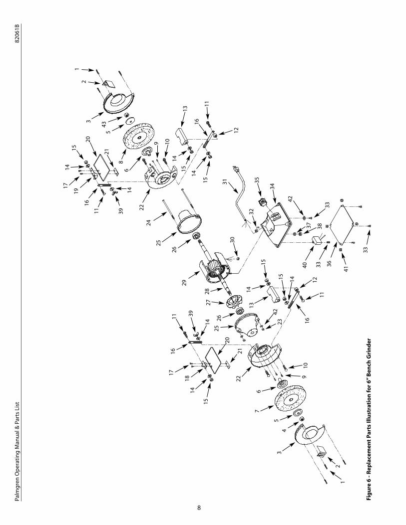
Fig
ure
6 -
Rep
lace
men
t P
arts
Illu
stra
tio
n f
or
6”
Ben
ch G
rin
der

9
ΔN
ot
Sho
wn
.*
Stan
dar
d h
ard
war
e it
em a
vaila
ble
loca
lly.
†N
ot
avai
lab
le a
s a
rep
air
par
t.
RE
PL
AC
EM
EN
T P
AR
TS
LIS
T F
OR
6”
BE
NC
H G
RIN
DE
R
Palm
gre
n O
per
atin
g M
anu
al &
Par
ts L
ist
8206
1B
Ref
.P
art
No.
Des
crip
tio
nN
um
ber
Qty
.
11 /4-
20 x
1 /2” P
an h
ead
scr
ew*
6
2Sp
ark
gu
ard
2446
1.00
2
3W
hee
l gu
ard
cov
er24
462.
092
41 /2”
-12
Hex
nu
t (L
H t
hre
ad)
0006
4.00
1
5Fl
ang
e18
904.
002
6In
ner
wh
eel f
lan
ge
1731
5.00
2
7G
rin
din
g w
hee
l (36
co
arse
gri
t)02
034.
001
8G
rin
din
g w
hee
l (60
med
. gri
t)02
033.
001
91 /4-
20 x
3 /8” F
lan
ge
scre
w*
6
105 /16
-18
x 1¼
” Car
riag
e b
olt
*4
115 /16
-18
x 1½
” Car
riag
e b
olt
*4
12Sp
acer
0402
8.00
2
13To
ol r
est
0403
0.00
2
145 /16
” Fla
t w
ash
er*
8
155 /16
”-18
Hex
nu
t*
6
16U
pri
gh
t04
029.
004
17#1
0-24
x 3 /8”
Pan
hea
d s
crew
*4
18U
pp
er e
yesh
ield
bra
cket
(lef
t)00
284.
011
19U
pp
er e
yesh
ield
bra
cket
(rig
ht)
0028
2.01
1
20Ey
esh
ield
0028
1.00
2
21Lo
wer
eye
shie
ld b
rack
et00
280.
002
22W
hee
l gu
ard
2446
3.09
1
235m
m-0
.8 H
ex n
ut
*2
245-
0.8
x 20
0mm
Pan
hea
d s
crew
0404
0.00
2
25En
dsh
ield
1661
7.09
2
Ref
.P
art
No.
Des
crip
tio
nN
um
ber
Qty
.
26B
eari
ng
620
2Z01
540.
002
27M
oto
r fa
n01
608.
001
28A
rmat
ure
†1
29St
ato
r w
ith
ho
usi
ng
†1
30G
rom
met
0106
6.00
1
31Li
ne
cord
0006
7.00
1
32St
rain
rel
ief
0405
5.00
1
33#1
0-24
x 1 /4”
Fla
ng
e sc
rew
*6
34B
ase
2375
7.09
1
35Ro
cker
sw
itch
wit
h k
ey08
066.
001
36C
over
2375
8.00
1
371 /4”
Lo
ck w
ash
er*
2
381 /4”
-20
Hex
nu
t*
2
395 /16
”-18
Win
g n
ut
*2
40C
apac
ito
r16
908.
001
41B
um
per
2399
1.00
4
42#1
0 Se
rrat
ed w
ash
er*
3
431 /2”
-12
Hex
nu
t (R
H t
hre
ad)
0054
8.00
1
ΔO
per
ato
rs m
anu
al25
139.
191
Rec
om
men
ded
Acc
esso
ries
ΔC
ast
iro
n t
oo
l sta
nd
7010
11
ΔW
hee
l dre
sser
8290
11
ΔLi
gh
ted
eye
shie
ld82
903
1

10
Palm
gre
n O
per
atin
g M
anu
al &
Par
ts L
ist
8206
2B
Fig
ure
7 -
Rep
lace
men
t P
arts
Illu
stra
tio
n f
or
6”
Ben
ch G
rin
der
1
46
5
87
1025
27
46
47
21
203
2
48 43
12
24
14
19
15
40
37
26
26
38
39
17
18
11
45
30
34
26
42
36
35
30
33
31
32
29
1315
12
16
14
17
28
1043
12
18
44
41
29
23
48
3
2047
46 23
24
7
95
49
4
1
25
19
22
27
1213
16
45

11
Palm
gre
n O
per
atin
g M
anu
al &
Par
ts L
ist
8206
2B
ΔN
ot
Sho
wn
.*
Stan
dar
d h
ard
war
e it
em a
vaila
ble
loca
lly.
†N
ot
avai
lab
le a
s a
rep
air
par
t.
RE
PL
AC
EM
EN
T P
AR
TS
LIS
T F
OR
6”
BE
NC
H G
RIN
DE
R
Ref
.P
art
No.
Des
crip
tio
nN
um
ber
Qty
.
1#1
0-24
x 3 /8”
Pan
hea
d s
crew
*10
2D
ust
co
llect
or
ho
se08
070.
011
3Sp
ark
gu
ard
(Set
of 2
)16
841.
001
4W
hee
l gu
ard
cov
er24
464.
092
5Fl
ang
e18
904.
002
61 /2”
-12
Hex
nu
t (L
H t
hre
ad)
0006
4.00
1
7In
ner
wh
eel f
lan
ge
1731
6.00
2
8G
rin
din
g w
hee
l (36
co
arse
gri
t)02
034.
001
9G
rin
din
g w
hee
l (60
med
. gri
t)02
033.
001
103 /8-
16 x
1¼
” Hex
hea
d b
olt
*4
115-
0.8m
m H
ex n
ut
*2
123 /8”
Fla
t w
ash
er*
4
133 /8”
-16
Hex
nu
t*
2
145 /16
-18
x 11 /2”
Car
riag
e b
olt
*2
15Sp
acer
4028
.00
2
16To
ol r
est
0403
0.00
2
175 /16
” Fla
t w
ash
er*
2
185 /16
”-18
Hex
nu
t*
2
19B
rack
et04
029.
002
20#1
0-24
x 3 /8”
Pan
hea
d s
crew
*4
21U
pp
er e
yesh
ield
bra
cket
(lef
t)00
284.
011
22U
pp
er e
yesh
ield
bra
cket
(rig
ht)
0028
2.01
1
23Ey
esh
ield
0028
1.00
2
24Lo
wer
eye
shie
ld b
rack
et00
280.
002
25W
hee
l gu
ard
2446
5.09
2
26#1
0-24
x 1 /4”
Fla
ng
e sc
rew
3210
.00
6
271 /4-
20 x
3 /8” F
lan
ge
scre
w16
670.
006
Ref
.P
art
No.
Des
crip
tio
nN
um
ber
Qty
.
285-
0.8
x 2
00m
m P
an h
ead
scr
ew04
040.
002
29En
dsh
ield
1661
7.09
2
30B
eari
ng
620
2ZZ
0154
0.00
2
31M
oto
r fa
n01
608.
001
32A
rmat
ure
†1
33St
ato
r w
ith
ho
usi
ng
†1
34G
rom
met
0106
6.00
1
35Li
ne
cord
0006
7.00
1
36St
rain
rel
ief
0405
5.00
1
37B
ase
cove
r23
758.
001
38B
ase
2375
7.09
1
39Sw
itch
wit
h k
ey08
066.
001
40B
ase
bu
mp
er23
991.
004
411 /4”
Lo
ck w
ash
er*
2
421 /4”
-20
Hex
nu
t*
2
433 /8”
-16
Win
g n
ut
*2
44C
apac
ito
r16
908.
001
45#1
0 Se
rrat
ed w
ash
er*
3
466-
1.0
x 12
mm
Fla
ng
e sc
rew
1666
8.00
2
476m
m F
lat
was
her
*2
48K
no
b16
714.
002
491 /2”
-12
Hex
nu
t (R
H t
hre
ad)
0054
8.00
1
ΔO
per
ato
rs m
anu
al25
139.
191
Rec
om
men
ded
Acc
esso
ries
ΔC
ast
iro
n t
oo
l sta
nd
7010
11
ΔW
hee
l dre
sser
8290
11
ΔLi
gh
ted
eye
shie
ld82
903
1

12
Palm
gre
n O
per
atin
g M
anu
al &
Par
ts L
ist
8207
1B &
820
81B
Fig
ure
8 -
Rep
lace
men
t P
arts
Illu
stra
tio
n f
or
7”
and
8”
Ben
ch G
rin
der
s
1
45
710
10
12
11
1418
17
38
3935
1311
1214
18
27
1716
14
5
8
51
53
52
6
7
9
41
30
33
34
37
3737
4450
46
43
47
47
45
45
40
26
424141
1613
29
15
12
25
21
20
28
225
483
20
22
1949
23
24
12
10
10
49
3
19
27
2930
3132
48
23
24
236

13
Palm
gre
n O
per
atin
g M
anu
al &
Par
ts L
ist
8207
1B &
820
81B
ΔN
ot
Sho
wn
.*
Stan
dar
d h
ard
war
e it
em a
vaila
ble
loca
lly.
†N
ot
avai
lab
le a
s a
rep
air
par
t.
RE
PL
AC
EM
EN
T P
AR
TS
LIS
T F
OR
7”
AN
D 8
”B
EN
CH
GR
IND
ER
Ref
.P
art
No.
Fo
r:N
o.D
escr
ipti
on
82
07
1B
82
08
1B
Qty
.
1#1
0-24
x 7 /8”
Pan
hea
d s
crew
*–
10
1#1
0-24
x 1 /2”
Pan
hea
d s
crew
–*
10
2W
hee
l gu
ard
1684
0.09
2449
5.09
2
3Sp
ark
gu
ard
(Set
of 2
)16
910.
0016
910.
001
4W
hee
l gu
ard
cov
er16
637.
0924
496.
092
5Fl
ang
e24
497.
0024
497.
002
65 /8”
-11
Hex
nu
t (L
H t
hre
ad)
0008
8.00
0008
8.00
1
7In
ner
wh
eel f
lan
ge
2449
8.00
2449
8.00
2
8G
rin
din
g w
hee
l (36
co
arse
gri
t)02
036.
0002
038.
001
9G
rin
din
g w
hee
l (60
med
. gri
t)02
035.
0002
037.
001
103 /8-
16 x
1¼
” Hex
hea
d b
olt
**
4
11To
ol r
est
bra
cket
0805
9.00
0805
9.00
2
123 /8”
Fla
t w
ash
er*
*4
133 /8”
-16
Hex
nu
t*
*2
145 /16
-18
x 1¼
” Car
riag
e b
olt
**
2
15D
ust
co
llect
or
ho
se08
070.
0008
070.
001
16To
ol r
est
0806
1.01
0806
1.01
2
175 /16
” Fla
t w
ash
er*
*2
185 /16
”-18
Hex
nu
t*
*2
196m
m F
lat
was
her
**
2
20#1
0-24
x 3 /8”
Pan
hea
d s
crew
**
4
21U
pp
er e
yesh
ield
bra
cket
(lef
t)00
284.
0100
284.
011
22U
pp
er e
yesh
ield
bra
cket
(rig
ht)
0028
2.01
0028
2.01
1
23Ey
esh
ield
0028
1.00
0028
1.00
2
24Lo
wer
eye
shie
ld b
rack
et00
280.
0000
280.
002
253 /8”
-16
Win
g n
ut
**
2
265-
0.8
mm
Hex
nu
t*
*4
271 /4-
20 x
1 /2” H
ex h
ead
bo
lts
**
6
285-
0.8
x 22
8mm
Fla
ng
e sc
rew
1665
4.00
1665
4.00
4
29En
dsh
ield
1662
7.09
1662
7.09
2
Ref
.P
art
No.
Fo
r:N
o.D
escr
ipti
on
82
07
1B
82
08
1B
Qty
.
30B
eari
ng
620
4ZZ
0098
9.00
0098
9.00
2
31M
oto
r fa
n01
620.
0022
041.
001
32A
rmat
ure
††
1
33St
ato
r w
ith
ho
usi
ng
††
1
34G
rom
met
0106
6.00
0106
6.00
1
35Li
ne
cord
0006
7.00
0009
0.00
1
36St
rain
rel
ief
0405
5.00
0405
5.00
1
37#1
0-24
x 1 /4”
Fla
ng
e sc
rew
0321
0.00
–7
37#1
0-24
x 1 /4”
Fla
ng
e sc
rew
–03
210.
009
38B
ase
2449
9.09
2449
9.09
1
39Sw
itch
wit
h k
ey08
066.
0008
066.
001
40B
ase
cove
r24
500.
0024
500.
001
411 /4”
Lo
ck w
ash
er*
*8
421 /4”
-20
Hex
nu
t *
*2
43C
apac
ito
r cl
amp
–16
655.
001
44C
apac
ito
r16
895.
0016
646.
001
45#1
0 Se
rrat
ed w
ash
er*
*5
46B
ase
bu
mp
er23
991.
0023
991.
004
47W
avy
was
her
1664
0.00
1644
0.00
2
48K
no
b16
714.
0016
714.
002
496-
1.0
x 12
mm
Fla
ng
e sc
rew
1666
8.00
1666
8.00
2
50#1
0-24
x 3 /8”
Fla
ng
e sc
rew
0320
7.00
0320
7.00
1
515 /8”
-11
Hex
nu
t (R
H t
hre
ad)
0008
7.00
0008
7.00
1
52St
atio
nar
y sw
itch
–25
171.
001
53C
entr
ifug
al s
wit
ch–
2517
2.00
1
ΔO
per
ato
rs m
anu
al25
139.
1925
139.
191
Rec
om
men
ded
Acc
esso
ries
ΔC
ast
iro
n t
oo
l sta
nd
7010
170
101
1
ΔW
hee
l dre
sser
8290
182
901
1
ΔLi
gh
ted
eye
shie
ld82
903
8290
31

14
Palm
gre
n O
per
atin
g M
anu
al &
Par
ts L
ist
8210
1A
Fig
ure
9 -
Rep
lace
men
t P
arts
Illu
stra
tio
n f
or
10
” B
ench
Gri
nd
er
1
3
46
5
78
12 11 14
1817
50
38
393513
10
12
14
18
27
4117
16
14
555
7
9
11
48
492
33
34
37
52
43
47
46
46
46
46
45
40
44
51
41
42
16
13
3015
12
56
53
53
54
20
292826
56
19
52
3
20
22
5154 23
24
1253
53
21
2741
2930
31
36
2
2
32
28
23 24
25

15
Palm
gre
n O
per
atin
g M
anu
al &
Par
ts L
ist
8210
1A
ΔN
ot
Sho
wn
.*
Stan
dar
d h
ard
war
e it
em a
vaila
ble
loca
lly.
†N
ot
avai
lab
le a
s a
rep
air
par
t.
RE
PL
AC
EM
EN
T P
AR
TS
LIS
T F
OR
10
”B
EN
CH
GR
IND
ER
Ref
.P
art
No.
Des
crip
tio
nN
um
ber
Qty
.
11 /4-
20 x
3 /4” P
an h
ead
scr
ew*
10
2#1
0-24
x 3 /8”
Fla
ng
e sc
rew
0320
7.00
3
3Sp
ark
gu
ard
(Set
of 2
)16
910.
001
4W
hee
l gu
ard
cov
er16
911.
092
5Fl
ang
e24
480.
002
61”
-8 H
ex n
ut
(LH
th
read
)00
111.
001
7In
ner
wh
eel f
lan
ge
2448
1.00
2
8G
rin
din
g w
hee
l (36
co
arse
gri
t)02
040.
001
9G
rin
din
g w
hee
l (60
med
. gri
t)02
039.
001
10C
apac
ito
r16
895.
001
11To
ol r
est
bra
cket
0805
9.00
2
123 /8”
Fla
t w
ash
er*
4
133 /8”
-16
Hex
nu
t*
2
145 /16
-18
x 1¼
” Car
riag
e b
olt
*2
15D
ust
co
llect
or
ho
se08
070.
021
16To
ol r
est
0806
1.01
2
175 /16
” Fla
t w
ash
er*
2
185 /16
”-18
Hex
nu
t*
2
19W
avy
was
her
1662
0.00
1
20#1
0-24
x 3 /8”
Pan
hea
d s
crew
*4
21U
pp
er e
yesh
ield
bra
cket
(lef
t)00
284.
011
22U
pp
er e
yesh
ield
bra
cket
(rig
ht)
0028
2.01
1
23Ey
esh
ield
0028
1.00
2
24Lo
wer
eye
shie
ld b
rack
et00
280.
002
25W
hee
l gu
ard
(lef
t)16
912.
091
26W
hee
l gu
ard
(rig
ht)
1671
5.09
1
275 /16
-18
x 5 /8”
Hex
hea
d b
olt
*6
281 /4-
20 x
2” F
lan
ge
scre
w03
209.
008
29En
dsh
ield
1691
3.09
2
30B
eari
ng
620
6ZZ
0029
7.00
2
31M
oto
r fa
n01
639.
001
Ref
.P
art
No.
Des
crip
tio
nN
um
ber
Qty
.
32A
rmat
ure
†1
33St
ato
r w
ith
ho
usi
ng
†1
34G
rom
met
1691
6.00
2
35Li
ne
cord
0009
0.00
1
36St
rain
rel
ief
0160
1.00
1
37St
rain
rel
ief p
late
0817
2.00
1
38B
ase
1691
7.09
1
39Sw
itch
wit
h k
ey08
066.
001
40Sw
itch
pla
te08
173.
001
415 /16
” Lo
ck w
ash
er*
10
425 /16
”-18
Hex
nu
t*
4
43C
apac
ito
r cl
amp
1691
8.00
1
44C
apac
ito
r08
174.
001
45C
apac
ito
r ca
p01
638.
002
46#1
0-24
x 1 /4”
Fla
ng
e sc
rew
0321
0.00
10
47#1
0 Se
rrat
ed w
ash
er*
1
48St
atio
nar
y sw
itch
0817
5.00
1
49Ro
tati
ng
sw
itch
0029
9.00
1
50B
ase
cove
r16
919.
001
516m
m ”
Flat
was
her
*2
52K
no
b16
714.
002
533 /8-
16 x
11 /4”
Hex
hea
d b
olt
*4
546-
1.0
x 12
mm
Fla
ng
e sc
rew
1666
8.00
2
551”
-8 H
ex n
ut
(RH
th
read
)00
110.
001
563/
8”-1
6 W
ing
nu
t*
2
ΔO
per
ato
rs m
anu
al25
139.
191
Rec
om
men
ded
Acc
esso
ries
ΔC
ast
iro
n t
oo
l sta
nd
7010
11
ΔW
hee
l dre
sser
8290
21
ΔLi
gh
ted
eye
shie
ld82
903
1

Palmgren Operating Manual & Parts List 82061B, 82062B, 82071B, 82081B & 82101A
TWO YEAR LIMITED WARRANTY
Palmgren warrants to the original purchaser that all products covered under this warranty are free from defects in material and workman-ship for a period of two years from the date of the original purchase.
We will repair or replace at our option, any part or parts of the product and accessories covered under this warranty which, after examina-tion, proves to be defective in workmanship or material during the warranty period.
This warranty does not apply to repair or replacement required due to misuse, abuse, normal wear and tear, or repairs attempted or made byother than our Service Department or an Authorized Service Representative. Proper use and care instructions are provided in the operator’smanual. Failure to follow these instructions will void the warranty.
This warranty gives you specific legal rights and you may also have other legal rights which may vary from state to state.
Responsibility of Original Purchaser (Initial User):
• To process warranty claim on this product, DO NOT return it to the retailer. The product must be evaluated by Palmgren. Call (800) 621-6145 for instructions.
• Retain original cash register sales receipt or invoice as proof of purchase for warranty work.
• Use reasonable care in the operation and maintenance of the product as described in the operator’s manual.
• Deliver or ship the product(s) to Palmgren. Freight costs, if any must be paid by the purchaser.
This Warranty Does Not Cover:
• Merchandise sold as reconditioned, used as rental equipment, and floor or display models.
• Repair and transportation costs of merchandise determined not to be defective.
• Expendable parts or accessories supplied with the product which are expected to become inoperative or unusable after a reasonableperiod of use. See the operator’s manual for a list of accessories and expendable parts.