Embed Size (px)
Citation preview

U.O.No. 8962/2019/Admn Dated, Calicut University.P.O, 07.07.2019
Biju George K
Assistant Registrar
Forwarded / By Order
Section Officer
File Ref.No.3128/GA - IV - J1/2013/CU
UNIVERSITY OF CALICUT
Abstract
General and Academic - Faculty of Science - Syllabus of BSc Electronics Programme (LRP) under CBCSS UGRegulations 2019 with effect from 2019 Admission onwards - Implemented- Orders Issued
G & A - IV - J
Read:-1. U.O.No. 4368/2019/Admn dated 23.03.20192. Item No. 1 in the minutes of the meeting of the Board of Studies in Electronics heldon 14.06.20193. Item No.I.36 in the minutes of the meeting of Faculty of Science held on 27.06.2019
ORDER
The Regulations for Choice Based Credit and Semester System for Under Graduate(UG) Curriculum- 2019 (CBCSS UG Regulations 2019) for all UG Programmes under CBCSS-Regularand SDE/Private Registration w.e.f. 2019 admission has been implemented vide paper read firstabove . The meeting of Board of Studies in Electronics held on 14.06.2019 has approved the Scheme andSyllabus of BSc Electronics Programme in tune with the new CBCSS UG Regulations with effect from2019 Admission onwards, vide paper read second above. The Faculty of Science at its meeting held on 27.06.2019 has approved the minutes of themeeting of the Board of Studies in Electronics held on 14.06.2019, vide paper read third above. Under these circumstances , considering the urgency, the Vice Chancellor has accorded sanction toimplement the Scheme and Syllabus of BSc Electronics Programme in accordance with thenew CBCSS UG Regulations 2019, in the University with effect from 2019 Admission onwards, subjectto ratification by the Academic Council. The Scheme and Syllabus of BSc Electronics Programme (LRP) in accordance with CBCSSUG Regulations 2019, is therefore implemented in the University with effect from 2019Admission onwards. Orders are issued accordingly. (Syllabus appended).
ToThe Principals of all Affiliated CollegesCopy to: PS to VC/PA to PVC/ PA to Registrar/PA to CE/JCE I/JCE IV/DoA/EX and EGSections/GA I F/CHMK Library/Information Centres/SF/DF/FC
Page 1 of 60

UNIVERSITY OF CALICUT
SYLLABUS
For
B.Sc Electronics (CBCSS UG 2019)
Under Choice Based Credit Semester System
(w.e.f. 2019 Admission)
Board of Studies in Electronics
University of Calicut
Page 2 of 60

1
UNIVERSITY OF CALICUT
B.Sc. ELECTRONICS
CORE AND COMPLEMENTARY
PROGRAMMES
STRUCTURE, SCHEME and
SYLLABUS
2019 Admission Onwards
Page 3 of 60

2
REGULATIONS GOVERNING
BACHELOR OF SCIENCE IN ELECTRONICS
1.0 Title of the programme:
This programme shall be called BACHELOR OF SCIENCE IN ELECTRONICS under Choice
Based Credit and Semester System forUndergraduate (UG) Curriculum -2019.
1.0 Title of the programme:
This programme shall be called BACHELOR OF SCIENCE IN ELECTRONICS under Choice
Based Credit and Semester System for Undergraduate (UG) Curriculum -2019.
2. Highlights of the programme
2.1 Aim and objective:
Emerging trends and stimulating developments in the field of science, increasing opportunities
and demands at workplace have made it imperative that the undergraduate science courses be
redesigned to cater to the professional aspirations of the students. The present world is in need of
professionals who are experts in the respective fields and hence restructuring of any science course
should possess components as catalyst to achieve the goals. The boundaries between different domains
of science are disappearing and more exciting developments are being reported from areas at the
crossing point of disciplines. In response to these changes taking place in society, the University of
Calicut has embarked on a major restructuring exercise for its science courses by introducing BSc
courses in alternate pattern.
BSc ELECTRONICS Programme is one such course in science stream under Choice Based
Credit and Semester System of the University of Calicut. This restructured undergraduate science
course provides students with a broad exposure to the critical domains of sciences with adequate
background of mathematical sciences. The tools and techniques of computer applications, industry
automation, electronics and analytical techniques have a major role in the curriculum. The audit courses
offered ensure adequate exposure to global and local concerns that explore the many aspects of societal
relevance and environmental awareness.It also gives opportunity to explore the multi-disciplinary
nature of science.
This course is to equip 10+2 (Science Group) students with the theory of Electronic
Scienceand also to train them in achieving technical expertise in Electronic Application. We aim to
provide a solid foundation in all aspects of Electronics and to show a broad spectrum of modern trends
in the subject and also to develop experimental, computational and mathematical skills of students. The
Page 4 of 60

3
syllabi are framed in such a way that it generates graduates of the calibre sought by industries and
public service as well as academic teachers and researchers of the future.
2.2 ProgrammeOutcome :
On completion of the B.Sc Electronics Programme, the student will:
▪ Have basic communicative skill in the English language
▪ Have environmental and civic awareness
▪ Communicative skills and literary sensibility in languages other than English
▪ Have sound knowledge of the theory behind core subjects like, Electronic components,
Electronic measuring and testing instruments, Analog and Digital IC’s, Electronic circuit
design and implementation, Troubleshooting and maintenance of electronic and electrical
devices.
▪ Have sound skills in assembly Language and High Level Language programming, Interfacing
of electronic devices with computers, etc
▪ Be in a position to develop industrial and entrepreneur applications.
2.3 Higher Studies: These students can continue to take up courses such as MSc Electronics, MSc
Instrumentation Technology, MCA ,MBA,etc.
2.4 Eligibility
Candidate of admission to the B.Sc Electronics Programme should have passed the Higher
secondary / Technical higher secondary / Vocational Higher secondary examinations of Govt. of
Kerala or CBSE or IELE or any other examinations recognized as equivalent there to by the
University of Calicut with Mathematics or Electronics or Computer Science or Computer
Applications as one of the optional subjects.
2.5 Duration of the Programme
Duration of the programme shall be 6 semesters. Each semester should have 90 instructional days with
5 hours of instruction per day 5-days a week system. The University will conduct semester-end
examinations.
Page 5 of 60

4
Programme Structure
Sem
este
r
Cou
rse
No.
Courses Course
Code Course Title
Contact
Hours
Cre
dit
s
Th
eory
Lab
Tota
l
Sem
este
r I
1 Common Course 1 English course I 5 - 5 4
2 Common Course 2 English course II 4 - 4 3
3 Common Course 3 Additional Language
course I 5 - 5 4
4 Core Course 1 ELE1B01 Basic Electronics and
Network Theorems 1 2 3 2
5 1st Complimentary Course 1 Mathematics – I 4 - 4 3
6 2nd Complimentary Course 1 Optional – 1 4 4 3
Total 25 19
Sem
este
r II
1 Common Course 4 English Course III 5 - 5 4
2 Common Course 5 English Course IV 4 - 4 3
3 Common Course 6
Additional Language
course III 5 - 5 4
4 Core Course 2 ELE2B02 Electronic Circuits 1 2 3 2
5 Core Lab 1
(Exam) ELE2B03
Basic Electronics and Network Theorems Lab
1 stSem. Lab
exam.
2
6 Core Lab 2
(Exam) ELE2B04 Electronic Circuits Lab
2 nd
Sem. Lab
exam
2
7 1st Complimentary Course 2 Mathematics -II 4 - 4 3
8 2nd Complimentary Course 2 Optional - 2 4 - 4 3
Total 25 23
Page 6 of 60

5
Sem
este
r
Cou
rse
No.
Courses Course
Code Course Title
Contact
Hours
Cre
dit
s
Th
eory
Lab
Tota
l
Sem
este
r II
I
1 General Course I
( Common to LRP group of
boards )
Python 4 - 4 4
2 General Courser-II
( Common to LRP group of
boards )
Sensors and Transducers 4 - 4 4
3 Core Course 3 ELE3B05 Digital Electronics 4 2 6 3
4 Core Lab Skill Development Lab I - 1 1 -
5 1st Complimentary Course 3
Mathematics –III 5 - 5 3
6 2nd Complimentary Course 3 Optional -3 5 - 5 3
Total 25 17
Sem
este
r IV
1 General Course –III
( Common to LRP group of
boards )
Data Communication &
Optical Fibers 4 - 4 4
2 General Course –IV
( Common to LRP group of
boards )
Microprocessors –
Architecture and
Programming
4 - 4 4
3 Core Course 4 ELE4B06 Analog Integrated
Circuits 4 2 6 3
4 Core Lab 3 ELE4B07 Digital Electronics Lab 3 rd Sem. Lab
exam
2
5 Core Lab 4 ELE4B08 Analog Integrated
Circuits LAB
4th Sem. Lab
exam
2
6 Core Lab 5
(3 rd and 4th Sem. Lab exam
+ Mini Project)
ELE4B09 Skill Development Lab II
- 1 1 1
7 1st Complimentary Course-4 Mathematics-IV 5 5 3
8 2nd Complimentary Course-4 Optional 4 3 2 5 3
Total 25 22
Page 7 of 60

6
Sem
este
r
Cou
rse
No.
Courses Course Code Course Title
Contact
Hours
Cre
dit
s
Th
eory
Lab
Tota
l
Sem
este
r V
1 Core Course-5 ELE5B10 Electromagnetic Theory 4 - 4 4
2 Core Course-6 ELE5B11 Microcontroller & Interfacing 4 3 7 3
3 Core Course-7 ELE5B12 Network Theory 4 - 4 4
4 Open Course
Choose a Course
from the List
ELE5D01 Computer Hardware 3 -
3 3
ELE5D02 Digital Fundamentals
ELE5D03 Electronics Fundamentals
5 Microprocessor programming and
interfacing lab (8085 and raspberry
pi)
- 3 3 -
6 Industrial Visit
7 Project Work 4 4
Total 25 14
Sem
este
r V
I
Sem
este
r V
I
1 Core Course-8 ELE6B13 Communication System 4 3 7 4
2 Core Course-9 ELE6B14 Principles of DSP 4 3 7 4
3 Core Course-
10
ELE6B15 Microwave Theory and Techniques
4 - 4 4
4
Core Course
Elective
Choose a Course(Elective) 3 - 3 3
ELE6B16a Optical Communication
ELE6B16b Industrial Electronics
ELE6B16c Control Systems
ELE6B16d Verilog & FPGA Based System
Design
5 Core Lab -6
(Exam)
ELE6B17 Microprocessor & Microcontroller
programming and interfacing lab
(8085,raspberry pi,8051and Arduino)
5th&
6thsem.lab
Exam
3
6 Core Lab -7
(Exam)
ELE6B18 Communication system Lab
5thsem.lab
Exam
2
7 Core Lab -8
(Exam)
ELE6B19 Principles of DSP lab
6th sem.lab
Exam
2
8 Core Lab -9 ELE6B20 Industrial Visit
Report ( 1 credit ) & Project Work
( 2 credit ) V
0 4 4 3
Total 25 25
Page 8 of 60

7
Core Labs Practical examinations shall be conducted in the even semester (II, IV, and VI)
SEMESTER II
Core Lab1 ELE2B03 Basic Electronics and Network Theorems Lab Core Lab2 ELE2B04 Electronic Circuits Lab
SEMESTER IV
Core Lab3 ELE4B07 Digital Electronics Lab Core Lab4 ELE4B08 Analog Integrated Circuits LAB Core Lab5 ELE4B09 Skill Development Lab
SEMESTER VI
Core Lab6 ELE6B17 Microprocessor & Microcontroller programming and
Interfacing lab Core Lab7 ELE6B18 Communication system Core Lab8 ELE6B19 Principles of DSP lab Core Lab9 ELE6B20 Industrial Visit Report & Project Work Viva Voce
Course Evaluation (Theory) The evaluation scheme for each course shall contain two parts
1) Internal assessment 2)External Evaluation
20% weight shall be given to the internal assessment. The remaining 80% weight shall be for the
external evaluation.
Internal Assessment 20% of the total marks in each course are for internal examinations. The internal assessment
shall be based on a predetermined transparent system involving writtentests, Class room participation
based on attendance in respect of theory courses and labinvolvement/records attendance in respect of
Practical Courses.
Components with percentage of marks of Internal Evaluation of Theory Courses are-
Test paper 40%
Assignment 20%
Seminar 20%
Class room participation based on attendance 20%.
For the test paper marks, at least one test paper should be conducted. If more test papers
areconducted, the mark of the best one should be taken.There shall not be any chance for
improvement forinternal marks.
The Split up of of marks for Test paper and Class Room Paticipation (CRP) for internal
evaluationare as follows.
Page 9 of 60

8
Split up of marks for Test paper
Split up of of marks for Test
paper
Out of 8(Maximum internal
marks is 20)
Out of 6(Maximum internal
marks is 15)
Less than 35% 1 1
35%- 45% 2 2
45% - 55% 3 3
55% - 65% 4 4
65% -85% 6 5
85% -100% 8 6
Split up of of marks for Class Room Participation
Range of CRP Out of 4 (Maximum internal
marks is 20)
Out of 3 (Maximum internal
marks is 15)
50% ≤CRP <75% 1 1
75% ≤CRP <85% 2 2
85 % and above 4 3
Course Evaluation (Practicals)
The practical examinations for the complementary and core courses shall be conducted by the
University at the end of semesters 2, 4 and 6 respectively. The examiners shall be selected from a
panel of experts prepared by the University. For each examination centre there shall be one external
examiner (Chief) and one internal examiner (Additional).
For the evaluation of practical examination 20% weightage is given for internal assessment
and 80% weightage is given for university exam.Record 60% lab involvement 40% as far as internal
is concerned.(if a fraction appears in internal marks, nearest whole number is to be taken).
Refer CBCSS UG Regulations 2019 for more details.
Course Evaluation (Projects)
1. Evaluation of the Project Report shall be done under Mark System.
2. The evaluation of the project will be done at two stages:
Page 10 of 60

9
1. Internal Assessment (supervising teachers will assess the project and award internal
Marks)
2. External evaluation (external examiner appointed by the University)
3. Marks secured for the project will be awarded to candidates, combining the internal
and external Marks
4. The internal to external components is to be taken in the ratio 1:4. Assessment of
different components may be taken as below.
Internal (20%) External (80%)
Components % of
Marks Components
% of
Marks
Punctuality and Log Book 20
Relevance of the Topic,
Statement of Objectives,
Methodology (Reference/
Bibliography)
20
Skill of doing project work 20 Presentation, Quality of
Analysis/Use of Statistical tools,
Findings and recommendations
30 Scheme/Organization of Report 30
Viva-Voce 30 Viva-Voce 50
1. External Examiners will be appointed by the University from the list of VI semester Board of
Examiners in consultation with the Chairperson of the Board.
2. The chairman of the VI semester examination should form and coordinate the evaluation teams
and their work.
3. Internal Assessment should be completed 2 weeks before the last working day of semester.
4. In the case of courses with practical examination, project evaluation shall be done
along with practical examinations.
5. Chairman Board of Examinations, may at his discretion, on urgent requirements,
make certain exception in the guidelines for the smooth conduct of the evaluation
of project.
PASS CONDITIONS
Page 11 of 60

10
• Submission of the Project Report and presence of the student for viva are compulsory for
internal evaluation. No marks shall be awarded to a candidate if she/ he fails to submit the
Project Report for external evaluation.
• The student should get a minimum P Grade in aggregate of External and Internal.
• There shall be no improvement chance for the Marks obtained in the Project Report.
• In the extent of student failing to obtain a minimum of Pass Grade, the project work may be re-
done and a new internal mark may be submitted by the Parent Department. External
examination may be conducted along with the subsequent batch.
Sem
este
r Credit for
Tota
l
Hours for Core Hours for
Tota
l H
ou
rs
per
wee
k
Core
Com
pli
men
tary
En
g.
SL
Gen
eral
Th
eory
Lab
Tota
l
En
g
SL
Com
pli
mn
tary
I 2 6 7 4 19 1 2 3 9 5 8 25
II 4 6 7 4 21 1 2 3 9 5 8 25
III 3 6 8 17 12 3 15 - - 10 25
IV 8 6 8 22 12 3 15 - - 10 25
V 14 15 15 10 25 - - - 25
VI 25 26 15 10 25 - - - 25
Total 58* 24 14 8 16 120
* (Including Open Course)
Work load (Core)
Semester Theory Lab Total Odd Sem
Total
Even Sem
Total
I 1 2x2 6
58 - III 12 3x2 18
V 15 10x2 35
II 1 2x2 6
- 58 IV 12 3x2 18
VI 15 10x2 35 Question paper -Core and Complimentary
Scheme of Examinations:
The external QP with 80 marks and Internal examination is of 20 marks. Duration of each
external examination is 2.5 Hrs. The pattern of External Examination is as given below. The students
can answer all the questions in Sections A&B. But there shall be Ceiling in each section. Page 12 of 60
11
Section A
Short answer type carries 2 marks each - 15 questions Ceiling - 25
Section B
Paragraph/ Problem type carries 5 marks each - 8 questions Ceiling - 35
Section C
Essay type carries 10 marks (2 out of 4) 2X10=20
Question paper - Open Course
Scheme of Examinations:
The external QP with 60 marks and Internal examination is of 15 marks. Duration of each
external examination is 2 Hrs. The pattern of External Examination is as given below. The students
can answer all the questions in Sections A& B. But there shall be Ceiling in each section.
Section A
Short answer type carries 2 marks each - 12 questions Ceiling - 20
Section B
Paragraph/ Problem type carries 5 marks each - 7 questions Ceiling - 30
Section C
Essay type carries 10 marks (1 out of 2) 1X10=10
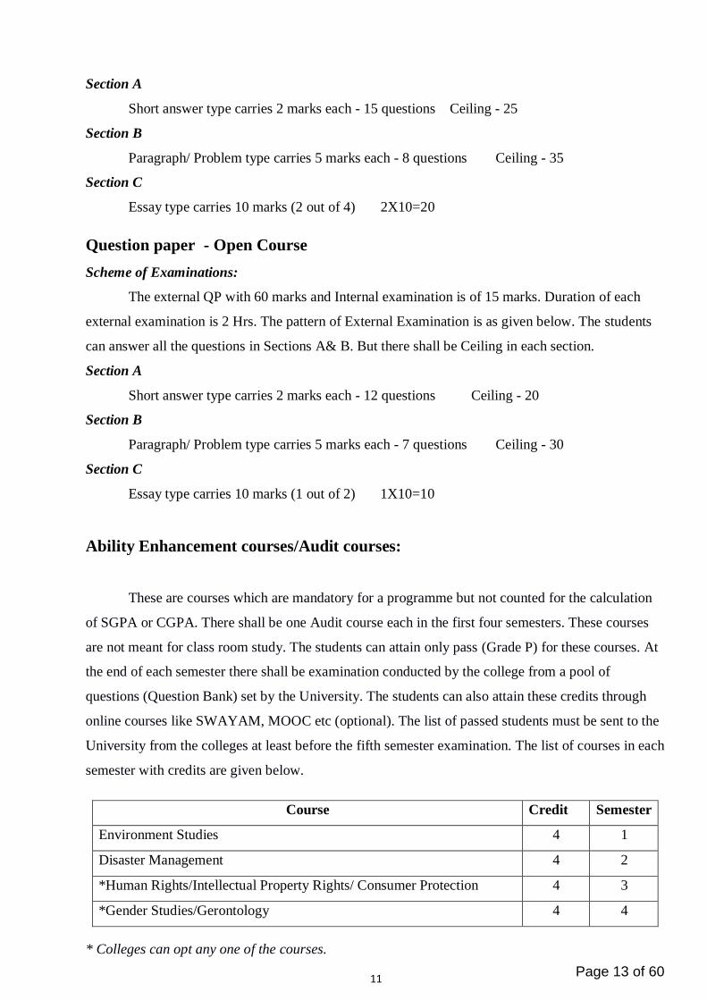
Ability Enhancement courses/Audit courses:
These are courses which are mandatory for a programme but not counted for the calculation
of SGPA or CGPA. There shall be one Audit course each in the first four semesters. These courses
are not meant for class room study. The students can attain only pass (Grade P) for these courses. At
the end of each semester there shall be examination conducted by the college from a pool of
questions (Question Bank) set by the University. The students can also attain these credits through
online courses like SWAYAM, MOOC etc (optional). The list of passed students must be sent to the
University from the colleges at least before the fifth semester examination. The list of courses in each
semester with credits are given below.
Course Credit Semester
Environment Studies 4 1
Disaster Management 4 2
*Human Rights/Intellectual Property Rights/ Consumer Protection 4 3
*Gender Studies/Gerontology 4 4
* Colleges can opt any one of the courses.
Page 13 of 60

12
Evaluation of Audit courses:
The examinaton shall be conducted by the college itself from the Question Bank prepared by the
University. The Question paper shall be of 100 marks of 3 hour
duration.
Extra credit Activities:
Extra credits are mandatory for the programme. Extra credits will be awarded to students who
participate in activities like NCC, NSS and Swatch Bharath. Those students who could not join in
any of the above activities have to undergo Calicut University Social Service Programme (CUSSP).
Extra credits are not counted for SGPA or CGPA.
Attendance:
A student shall be permitted to appear for the semester examination, only ifhe/she secures not less
than 75% attendance in each semester. Attendance shall be maintained bythe Department concerned.
Condonation of shortage of attendance to a maximum of 10% in thecase of single condonation and
20% in the case of double condonation in a semester shall begranted by University remitting the
required fee. Benefits of attendance may be granted to studentswho attend the approved activities of
the college/university with the prior concurrence of the Headof the institution. Participation in such
activities may be treated as presence in lieu of theirabsence on production of participation/attendance
certificate (within two weeks) incurricular/extracurricular activities (maximum 9 days in a semester).
Students can avail ofcondonation of shortage of attendance in a maximum of four semesters during
the entireprogramme (Either four single condonations or one double condonation and two single
condonations during the entire programme) . If a student fails to get 65% attendance, he/she can
move to the next semester only if he/she aquires 50% attendance. In that case, a
provisionalregistration is needed. Such students can appear for supplementary examination for
suchsemesters after the completion of the programme.Less than 50% attendance
requiresReadmission.Readmission is permitted only once during the entire programme.
Page 14 of 60

13
Semester I Core Course 1
ELE1B01 - Basic Electronics and Network Theorems
Contact Hours per Week: 3 (1T + 2L)
Number of Credits: 2
Number of Contact Hours: 45 Hrs.
Course Outcome
To equip the students with basic components in electronics, identifying and testing them,
various measuring and testing instruments, assembling of electronic circuits and basic
techniques of troubleshooting.
• To learn the basics of electronic components
• To learn the basics of testing and measuring instruments
• To learn the circuit assembling
• To study circuit troubleshooting
Course Outline
Module I
Introduction to Electronics - Definition, applications, Electric field, Potential, Potential difference,
Electric current, Relation between charge and current, Concept of Voltage and Current Sources, AC
and DC. Concepts of open and short circuit, Ohm’s law, Electrical Resistance, Factors affecting
Resistance, Temperature coefficient, Resistivity, Load Resistance and load current, Power
dissipation, Passive components –R,C,L- Types, construction, symbols, specifications, Units ,Colour
coding, Testing.
Module II
Resistance in series and parallel, Kirchhoff’s Voltage Law (KVL), Kirchhoff’s Current Law (KCL),
Principle of Duality, Superposition Theorem.Thevenin’s Theorem.Norton’s Theorem.Reciprocity
Theorem. Maximum Power Transfer Theorem, Two Port Networks: h, y and z parameters.
Module III
Review of Structure of solids - Semiconductor materials, Intrinsic Semiconductors, Extrinsic
Semiconductors –Semiconductor Parameters - Intrinsic concentration, Mobility, Conductivity, Mass
action law, Energy gap, Drift and Diffusion Current,Semiconductor Diodes – PN junction, Junction
Theory, Depletion layer, Barrier potential ,forward and reverse biasing VI characteristics of PN
junction diode, Ideal diode, Static and Dynamic Resistance , Diode current equation, Diode notations,
diode testing, Special Diodes - Construction, Characteristics and applications of Zener diode, LED.
Module IV
Bipolar Junction Transistors – Types, Construction, Operation, Common Base configuration-input and
output characteristics, Common Emitter configuration- input and output characteristics, Common
collector configuration, Limits of operation. Field Effect Transistors – introduction, Types,
Page 15 of 60

14
Construction and Characteristics of JFET, Transfer Characteristics, Metal Oxide Semiconductor Field
Effect Transistors – Depletion Type, Enhancement Type.
UJT, SCR, – Construction, operation, characteristics and applications.
Text Books
1. NN Bhargava, DC Kulshreshta, SC Gupta “Basic Electronics and Linear Circuits” Tata McGraw-
Hill Publishing Company LTD
2. R.S. Sedha“A text book of applied Electronics” S Chand and Company LTD
3. Robert L. Boylestad, Louis Nashelsky “Electronic Devices and Circuit Theory” , 10th edition,
Pearson
4. Circuits and Networks – A. Sudhakar, S.P. Shyammohan, TMH Publications
References
1. Jacob millman, Christos c halkias, satyabratajit , 2nd edition “Electronic Devices and circuits”
2. B.L. Theraja, “Electrical and Electronic Engineering”, S Chand and Company LTD
3. R.K. Puri , V.K. Babbar, “Solid state physics and Electronics” , S Chand and Company LTD
4. V.K Mehta, “Principles of Electronics”, S Chand and Company LTDTata McGraw Hill Education
pvt Ltd.
5. S. A. Nasar, Electric Circuits, Schaum’s outline series, Tata McGraw Hill (2004)
6. Electrical Circuits, M. Nahvi and J. Edminister, Schaum’s Outline Series, Tata McGraw-
Hill.(2005)
Structure of Question Paper
The External question paper is of 2.5 hours duration with 80 marks. Question paper shall consist
of three sections. Section A contains 15short answer type questions of 2 marks each spanning the entire
syllabus and the candidate can score a maximum of 25 marks. Section B contains 8 paragraph / problem
type questions of 5 marks each; two questions from each module (2 Que x 4 module = 8 quest.), and
the candidate can score a maximum of 35 marks. Section C contains 4 essay type questions of 10 marks
each; one from each module, of which candidate has to answer 2.
Core Lab1
ELE2B03– Basic Electronics and Network Theorems Lab
Contact Hours per Week: 2 (2L)
Number of Credits: 2
Number of Contact Hours: 30 Hrs.
1. Familiarization of various measuring and testing equipments and power sources –
Voltmeter, Ammeter, Multimeter, LCR meter, CRO, Function Generator, etc.
2. Familiarization and testing of passive and active components.
3. Verification of equivalent resistance of series and parallel resistor networks, Voltage
division and Current division Rules
4. Verification of KVL and KCL
5. Diode Characteristics (Si, Ge, LED and Zener)
6. Common base transistor characteristics
7. Common emitter transistor characteristics
8. FET characteristics Page 16 of 60

15
9. UJT characteristics
10. SCR characteristics
References
1. NN Bhargava, DC Kulshreshta, SC Gupta “Basic Electronics and Linear Circuits”
Tata McGraw-Hill Publishing Company LTD
2. Jacob millman, Christos c halkias, satyabratajit , 2nd edition “Electronic Devices and
circuits”, Tata McGraw Hill Education pvt Ltd.
Semester II Page 17 of 60

16
Core Course 2
ELE2B02- Electronic Circuits
Contact Hours per Week: 3 (1T + 2L)
Number of Credits: 2
Number of Contact Hours: 45 Hrs.
Course Outcome
To equip the students with basic components in electronics, identifying and testing them,
various measuring and testing instruments, assembling of electronic circuits and basic
techniques of troubleshooting.
• To learn fundamentals of electronics
• To learn the circuit assembling
• To study circuit troubleshooting
Course Outline
Module I
Rectifiers – Half wave, full wave, bridge – average value, RMS value, PIV, Ripple factor, efficiency,
Comparison of rectifiers.Filters - C, L, LC,𝜋. Regulators – Zener diode voltage Regulator, Series
voltage Regulator, fixed voltage dc power supply circuit, Line and Load Regulation. Wave shaping
Circuits -Clipping circuits – Positive, Negative, Biased, Combination. Clamping Circuits – Positive,
Negative, Biased, Combination.RC Integrator and Low Pass Filter, RC Differentiator and High Pass
Filter.
Module II
Transistor Biasing – operating point, DC Load Line, Fixed bias, Emitter bias, Voltage Divider bias,
Collector feedback, Emitter follower, bias stabilization, BJT AC Analysis – Amplification in the ac
domain, BJT modelling, The Hybrid equivalent model – Amplifier analysis, cascaded system, RC
coupled BJT amplifier, tuned amplifier.
Module III
Frequency Response –Logarithm, decibel, general frequency consideration, gain bandwidth product,
Concept of power amplifiers – class A, class B, class C – operation – types of distortions in power
amplifiers, Complementary Symmetry Push-Pull Amplifier. Feedback - Concepts, types, effect on
gain, input impedance, output impedance, frequency distortion, noise, nonlinear distortion, bandwidth
and gain stability.
Module IV
Sinusoidal Oscillators –Criteria for oscillations-Barkhausen-oscillator operations, phase shift
oscillator, weinbridge oscillator, colpittsoscillator, Hartley oscillator, crystal oscillators, non sinusoidal
oscillators –classification, transistor as a switch, astable, monostable and bistablemultivibrators,
Schmitt trigger.
Text Books Page 18 of 60

17
1.Bhargava, Kurukshetra&Gupta ,”Basic Electronics and Linear Circuits”, Tata McGraw- Hill
Publishing LTD.
2. R S Sedha, “ Applied Electronics”, S.Chand and Company LTD.
3.Boylestad, Louis Nashelsky “Electronic Devices and Circuit Theory”, 10th edition, Pearson
References
1. Jacob Millman, Christos c Halkias, satyabratajit , 2nd edition “Electronic Devices and circuits”,
Tata McGraw Hill Education pvt Ltd.
2. V.K Mehta, “Principles of Electronics”, S Chand and Company LTD
3. Jacob Millman&Halkias “Integrated Electronics”, Tata McGraw Hill 2009
Structure of Question Paper
The External question paper is of 2.5 hours duration with 80 marks. Question paper shall consist
of three sections. Section A contains 15short answer type questions of 2 marks each spanning the entire
syllabus and the candidate can score a maximum of 25 marks. Section B contains 8 paragraph / problem
type questions of 5 marks each; two questions from each module (2 Que x 4 module = 8 quest.), and
the candidate can score a maximum of 35 marks. Section C contains 4 essay type questions of 10 marks
each; one from each module, of which candidate has to answer 2.
Core Lab 2
ELE2B04- Electronic Circuits Lab
Contact Hours per Week: 2 (2L)
Number of Credits: 2
Number of Contact Hours: 30 Hrs.
1. Rectifier circuits:Half Wave, Centre tapped and Bridge
2. Different Filter circuits (C,L,pi)
3. Zener Voltage Regulator
4. Diode clippers and Clampers
5. RC differentiator and HPF
6. RC Integrator and LPF
7. Voltage divider biasing circuits
7. Single stage transistor amplifier
8. RC Phase Shift Oscillator
9. Crystal Oscillators
10. AstableMultivibrator and Monostablemultivibrator using BJT
References
1. NN Bhargava, DC Kulshreshta, SC Gupta “Basic Electronics and Linear Circuits”
Tata McGraw-Hill Publishing Company LTD
Page 19 of 60

18
2. Jacob millman, Christos c halkias, satyabratajit , 2nd edition “Electronic Devices and
circuits”, Tata McGraw Hill Education pvt Ltd.
Page 20 of 60

19
Semester III
General Course 1
XXXXA11 – Python
Contact Hours per Week: 4
Number of Credits: 4
Number of Contact Hours: 60 Hrs.
Course Outcomes
• Understand various statements, data types and functions in Python
• Develop programs in Python programming language
• Understand the basics of Object oriented programming using Python
Course Outline
Module I
Introduction to python, features, IDLE, python interpreter, Writing and executing python scripts,
comments, identifiers, keywords, variables, data type, operators, operator precedence and associativity,
statements, expressions, user inputs, type function, eval function, print function.
Module II
Boolean expressions, Simple if statement, if-elif-else statement, compound boolean expressions,
nesting, multi way decisions. Loops: The while statement, range functions, the for statement, nested
loops, break and continue statements, infinite loops.
Module III
Functions, built-in functions, mathematical functions, date time functions, random numbers, writing
user defined functions, composition of functions, parameter and arguments, default parameters,
function calls, return statement, using global variables, recursion.
Module IV
String and string operations, List- creating list, accessing, updating and deleting elements from a list,
basic list operations. Tuple- creating and accessing tuples in python, basic tuple operations. Dictionary,
built in methods to access, update and delete dictionary values. Set and basic operations on a set.
Files- opening a file, reading and writing to file. OOPS concept and Python – OOPS terminology,
defining classes, creating objects, attributes, built in attributes.
References:
1. E. Balaguruswamy, Introduction to Computing and Problem Solving Using Python
2. Richard L. Halterman, Learning To Program With Python
3. Martin C. Brown, Python: The Complete Reference
Page 21 of 60

20
General Course II
XXXXA12 – Sensors and Transducers
Contact Hours per Week: 4
Number of Credits: 4
Number of Contact Hours: 60 Hrs.
Course Outcomes
The students will be able to
• Explain resistance, inductance and capacitance transducers.
• Perceive the concepts of temperature and pressure transducers.
• Perceive the concepts level transducers such as and flow transducers
• Explain Electromagnetic transducers and radiation sensors
• Explain force and torque transducers and sound transducers
Course Outline
Module I
Transducers: Definition, Principle of sensing & transduction, Classification, Characteristics of
transducers. Basic requirement of transducers.
Resistance Transducer: Basic principle – Potentiometer –Loading effects, Resistance strain gauge–
Types.
Inductance Transducer: - Basic principle – Linear variable differential transformer – RVDT-types.
Capacitance Transducer: Basic principle- transducers using change in area of plates – distance between
plates- variation of dielectric constants –Types
Module II
Thermal sensors: Resistance change type: RTD - materials, construction, types, working principle,
Thermistor - materials, construction, types, working principle, Thermo emf sensors: Thermocouple –
Principle and types, Radiation sensors: Principle and types.
Pressure Transducers: basic principle- different types of manometers-u tube manometer-well type
manometers.
Module III
Level transducer-continuous level measurement-discrete level measurement-mass –capacitive level
gauges
Flow Transducers: Bernoulli’s principle and continuity, Orifice plate, nozzle plate, venture tube,
Rotameter, anemometers, electromagnetic flow meter, impeller meter and turbid flow meter
Module IV
Hall effect transducers, Digital transducers, Piezo-electric sensors, eddy current transducers, tacho
generators and stroboscope, Magnetostrictive transducers
Radiation sensors: LDR, Photovoltaic cells, photodiodes, photo emissive cell types
Force and Torque Transducers: Proving ring, hydraulic and pneumatic load cell, dynamometer and
gyroscopes.
Page 22 of 60

21
Sound Transducers: Sound level meter, Microphone.
Text Books
1. D Patranabis, Sensors and Transducers, PHI, 2nd Edition.
2. E. A. Doebelin, Measurement Systems: Application and Design McGraw Hill, New York
3. A.K. Sawhney,- A course in Electrical & Electronic Measurement andInstrumentation,
DhanpatRai and Company Private Limited.
4. Murthy D.V.S., ―Transducers and Instrumentation, 2nd Edition, Prentice Hall of India Private
Limited, New Delhi, 2010.
5. S.Renganathan, ―Transducer Engineering, Allied Publishers, 2005
Core Course 3
ELE3B05- Digital Electronics
Contact Hours per Week: 7 (4T + 3L)
Number of Credits: 3
Number of Contact Hours: 60 Hrs.
Course Outcome
To equip the students with detailed knowledge in digital electronics, digital IC’s in the 74XX
Series. Many of the ideas are important to learn microprocessors.
To learn different number systems, logic gates, comparators, flip flops etc
Course Outline
Module I
Number systems – Decimal, Binary, Octal & Hexadecimal – conversions, Digital codes – BCD,
Excess 3, Gray code-conversions, ASCII codes,Boolean algebra & theorems, SOP & POS, De
Morgan‘s theorem, Simplification of Boolean expressions using Boolean Algebra & K Map(upto
four variables). Logic gates – AND, OR, NOT, NAND, NOR, XOR, XNOR. Universal Properties of
NAND and NOR.
Module II
Different Logic families: TTL, CMOS, ECL ,Open Collector & its characteristics.Combinational
circuits: Adders - Half adder and Full adder. Subtractors - Half and Full subtractor. Comparators - 1
bit magnitude & 2 bit magnitude. Decoders - 2 to 4 & 3 to 8. Encoders - Octal to Binary & Decimal
to BCD, Code converters - Gray to Binary, Binary to Gray and Binary to BCD.
Module III
Multiplexers: 2 input, 4 input & 8 input. Demultiplexers: 1 to 4 & 1 to 8. Realization of Boolean
expression using multiplexers and demultiplexers.Familarisation of popular ICs: 7483( 4 –Bit Binary
Adder), 74151( Multiplexer), 74154(De- Multiplexer) and its applications. Sequential circuits: Flip
Flops: RS latch, clocked RS, D, JK, T, Preset and Clear operations, Race-around condition in JK
Flip-Flop , Master slave JK. Applications – Latches, Shift registers - SISO, SIPO, PISO, PIPO,
typical circuits & applications as Ring counter and Johnson counter.
Page 23 of 60

22
Module IV
Counters: State diagram & State table. Asynchronous counters: Concepts and Design of 2bit & 4 bit
Up/Down counter, MOD counter. Synchronous counters, Familiarization of popular ICs: 7490
(Decade Counter), 4017 (Decade Counter/Divider with 10 Decoded Outputs) and 7446 (BCD to
Seven Segment Decoder).
Converters: ADC – Flash, Successive Approximation, Counter Ramp. DAC-Weighted Resistor and
R-2R Ladder.Parameters of DAC and ADC.
Text Books
1. Digital fundamentals - Thomalsfloyd
2. Anandkumar, Fundamentals of digital circuits, PHI, 2/e, 2012.
3. Digital Principles - Malvino
References
1. John M Yarbrough, Digital logic- Application and Design, Thomson Learning,2006.
2. John Wakerly, Digital Design Principles and Practice, Pearson,4/e, 2012.
3. Morris Mano,Ciletti, Digital Design, 4/e, Pearson ,4/e, 2009
4. Digital Integrated circuits - Taub and Schilling
Structure of Question Paper
The External question paper is of 2.5 hours duration with 80 marks. Question paper shall consist
of three sections. Section A contains 15short answer type questions of 2 marks each spanning the entire
syllabus and the candidate can score a maximum of 25 marks. Section B contains 8 paragraph / problem
type questions of 5 marks each; two questions from each module (2 Que x 4 module = 8 quest.), and
the candidate can score a maximum of 35 marks. Section C contains 4 essay type questions of 10 marks
each; one from each module, of which candidate has to answer 2.
Core Lab 3
ELE4B07- Digital Electronics Lab
Contact Hours per Week: 2 (2L)
Number of Credits: 2
Number of Contact Hours: 30 Hrs.
1. Logic gates
a. To verify the truth tables of NOT, AND, OR and XOR gates
b. To verify Demorgan’s theorem for two variables
c. Realization of SOP and POS expressions using Basic logic gates
2. Universal Gates
a. To verify the truth tables of NAND and NOR gates
b. To verify the universal properties of NAND and NOR gates
c. Realization of SOP and POS expressions using NAND and NOR gates
3. Adders
a. To realize half adder and Full adder circuits and verify the truth tables
b. To verify the operation of 7483 four bit parallel adder Page 24 of 60

23
4. Subtractors
a. To realize half subtractor and Full subtractor circuits and verify the truth tables
b. To construct and verify four bit subtractor using IC 7483
5. Comparators
a. To design and verify two bit magnitude comparator using gates
b. To verify the operation of 4 bit magnitude comparator IC 7485
6. Multiplexers
a. To verify the truth table of 4 to 1 multiplexer using IC 74153
b. To verify the truth table of 8 to 1 multiplexer using IC 74151
c. To realize a Boolean function (up to 3 variable) using multiplexer IC 74153/74151
7. De-Multiplexers and Decoders
a. To design 1 to 8 De multiplexer using IC 74138
b. To design 3 to 8 decoder using IC 74138
c. To study the operation of 4 line to 16 line Decoder / De-multiplexer IC 74154
d. To study the operation of seven segment decoder ICs
e. To realize Boolean Expressions using decoders
8. Encoders
a. To realize 4 to 2 line encoder and verify its truth table
b. To verify the operation of priority encoder IC 74148
9. Latches and Flip Flops
a. To realize RS latch using gates
b. To design and verify the operation of Clocked RS flip flop using NAND gates (7400)
c. To realize JK flip flop using NAND gates (7410 and 7400)
d. To verify the operation of D flip flop IC7474 and JK flip flop IC 7476
10. Counters
a. To design and construct asynchronous decade counter using JK flip flops
b. To design and construct synchronous decade counter using JK flip flops
c. To design and verify the operation of counter IC 7490 as MOD 2 Counter, MOD 5
Counter, MOD 8 Counter, MOD 10 Counter
11. Shift Registers
a. To design and verify the operation of 4 bit SISO,SIPO,PISO and PIPO shift registers
using D flip flop
12. Shift Register Counters
a. To design and verify the operation of 4bit Ring counter using D flip flops
b. To design and verify the operation of 4bit Johnson counter using D flip flops
* pin diagrams will be provided during Lab examination.
Page 25 of 60

24
Core Lab 5
ELE4B09- Skill Development Lab I
Contact Hours per Week: 1 (1L)
Number of Contact Hours: 15 Hrs.
1. Simulation and PCB design using software (Minimum Two Experiment)
a. Rectifier and Filter Circuits
b. RC Amplifier Circuit
c. Oscillator Circuits
d. Combinational Circuits
e. Counters using flip flops
f. Shift Registers
2. PCB fabrication - any one circuit
3. Assembling,Soldering and tesinng of the PCB fabricated circuit
Guidelines:
1. may use any software like SPICE, e-Sim, Kicad, Orcad, Proteus, etc
2. A printed record of laboratory work with schematics, simulation results and PCB layout as
print out must be submitted along with the report of Skill Development Lab.
3. Evaluation will be done at the end of 4th semester.
Page 26 of 60

25
Semester IV
General Course III
XXXXA13 – Data Communication & Optical Fibers
Contact Hours per Week: 4
Number of Credits: 4
Number of Contact Hours: 45 Hrs.
Course Outcomes
Course Outline
Module I
Introduction- Components, Networks, Protocols and standards, Basic Concepts: Line Configuration,
Topology Transmission mode, analog and digital signals, Encoding and modulating- analog-to-digital
conversion, digital to analog conversion, digital data transmission, DTE-DCE interface, modems, cable
modems. Transmission media: guided media, unguided media, and transmission impairment.
Module II
Multiplexing: Many to one/ one to many, frequency division multiplexing, wave division multiplexing,
TDM, multiplexing applications: the telephone system, Error detection and correction : types of errors,
detection , VRC, Longitudinal redundancy check, cyclic redundancy check, checksum, error
correction.
Module III
Data link Control: Line Discipline, flow control, error control, Data link Protocols: Asynchronous
Protocols, synchronous protocols, character oriented protocols, bit – oriented protocols, link access
procedures. Local Area Networks: Ethernet, token bus, token ring, FDDI, Comparison, Switching-
circuit switching, packet switching, message switching, integrated services digital networks (ISDN):
services, history, subscriber access to ISDN.
Module IV
(Derivation not required )
Overview Of Optical Fiber Communication - Introduction, historical development, general system,
advantages, disadvantages, and applications of optical fiber communication, optical fiber
waveguides, fiber materials, Optical Sources And Detectors- Introduction, LED’s, LASER diodes,
Photo detectors. Ray theory, cylindrical fiber, single mode fiber, cutoff wave length, mode field
diameter.
Text Book
1.Behrouz A. Forouzan, Data Communication and Networking, TMH
Page 27 of 60

26
2. Optical Fiber Communication – Gerd Keiser, 4th Ed., MGH, 2008.
Reference Books:
1. William Stallings: Data & Computer Communications, 6/e, Pearson Education.
2. William L. Schweber : Data Communication, McGraw Hill.
3. Electronic Communication Systems - Kennedy and Davis, TMH
4. Optical Fiber Communications– – John M. Senior, Pearson Education. 3rd Impression,2007.
5. Fiber optic communication – Joseph C Palais: 4th Edition, Pearson Education
General Course IV
XXXXA14 – Microprocessors – Architecture and Programming
Contact Hours per Week: 4
Number of Credits: 4
Number of Contact Hours: 45 Hrs.
Course Outcomes
Course Outline
Module I
General architecture of computer, Introduction to Microprocessor, Memory classification,
Introduction to 8085,Microprocessor bus organizations ,data bus, address bus, control bus. Memory
addressing, memory mapping. 8085 architecture in detail. General purpose registers and special
purpose registers, flag register -8085 pins and signals.
Module II
Assembly language programming basics.Opcode, Mnemonics etc. 8085 instruction set ,Data transfer
,Arithmetic and Logic, Shifting and rotating, Branching/Jump, Program control. Addressing
modes.Memory read and write cycle. Timing diagram. Instruction cycle , machine cycle and T-states.
Types of I/O addressing .Simple programs.
Module III
Types of programming techniques looping, indexing (pointers),delay generation. Stack in 8085, call
and return Instructions. Data transfer between stack and microprocessor. Subroutine and delay
programs.Interrupts in 8085. Interrupt driven programs. Interfacing - Programmable peripheral
devices - 8255A, 8254, 8237.
Module IV
Introduction to 8086/88 microprocessors – overview, 8086 internal architecture. The execution unit,
BIU, Registers, Flags, Segmentation, physical address calculation, addressing modes.
Page 28 of 60

27
Text Book
1. Ramesh S. Gaonkar, Microprocessor Architecture Programming and Application with 8085,
Prentice Hall
2. Doughles V Hall, Microprocessors and Interfacing: Programming and Hardware, Tata
McGraw Hill
Reference Book
1. Microprocessor and Microcomputer - Based system Design - M. Rafiquzzman - CRC press
2.A.PMathur, Introduction to Microprocessors, Tata McGraw-Hill Education
3.The Intel Microprocessors: 8086/8088, 80186/80188, 80286, 80386, 80486,
Pentium,Pentium Pro, Pentium II, III, IV and Core 2 with 64 bit Extensions, Barry B. Brey,Prentice
Hall Pearson
4. Microprocessors PC Hardware and Interfacing –N.Mathivanan – PHI
Core Course 4
ELE4B06- Analog Integrated Circuits
Contact Hours per Week: 7 (4T + 3L)
Number of Credits: 3
Number of Contact Hours: 60 Hrs.
Course Outcome
To equip the students with detailed knowledge of Analog IC’s like OPAMP 741, IC 555 etc.
To learn the basics of Amplifiers, filters, wave form generators, comparators, Multivibrators and
voltage regulators
Course Outline
Module I
BlockDiagram of typical operational Amplifiers – Ideal Op-amp characteristics – Op amp
Parameters – Inverting and Non-Inverting Amplifier – Voltage Follower- Summing
Amplifier-Differential Amplifier- Instrumentation Amplifier – V to I and I to V converter-
Integrator – Differentiator – Typical circuits – Applications.
Module II
Introduction – First order – Butter worth – Low pass, High pass, Band pass, Band
Reject, Notch and All pass Filters – Typical circuits- Applications. Wave form generators –
Square wave generator- Triangular and Sawtooth wave generators – sine wave oscillators
(Phase shift, Wien Bridge and Quadrature Oscillators).
Module III
Basic comparator – Characteristics – Typical comparator circuits using op amp – zero
crossing detector – Schmitt trigger – Typical Circuits – Operation – Application-Window
detector-Peak detector-Sample and Hold circuit-Clippers and Clampers-half wave Rectifier –
Precision Rectifier.Intoduction to Timer 555 -Monostable and AstaleMultivibrator -Application of
Page 29 of 60

28
Monostable and AstableMultivibrator
Module IV
Voltage controlled oscillator (VCO), PLL – blockdiagram, Operating principle, parameters, pinout,
function, applications and typical circuits.
Basic circuit configuration and characteristics of voltage regulators – Basic blocks oflinear voltage
regulator – three terminal fixed regulators (78XX and 79XX), AdjustablePositive voltage
Regulator(LM 317) and Adjustable Negative voltage Regulator(LM 337)-variable voltage Regulators
(723), Switching regulator, S.M.P.S – Typical circuits (Buck and Boost)–Applications.
Text book
1. Ramakant A. Gayakwad ,”Op-amp and Linear ICs”, Prentice-Hall of India
Private LTD.
2. Botkar,” Integrated Circuits”
Reference
1. Mottershed,” Electronic Devices and circuits”,
2. Millman&Halkias,”Integrated Electronic”, Tata McGraw-Hill Publishing LTD.
3. Tobey &Buelsman ,”Op-amp Design and Application”,
Structure of Question Paper
The External question paper is of 2.5 hours duration with 80 marks. Question paper shall consist
of three sections. Section A contains 15short answer type questions of 2 marks each spanning the entire
syllabus and the candidate can score a maximum of 25 marks. Section B contains 8 paragraph / problem
type questions of 5 marks each; two questions from each module (2 Que x 4 module = 8 quest.), and
the candidate can score a maximum of 35 marks. Section C contains 4 essay type questions of 10 marks
each; one from each module, of which candidate has to answer 2.
Core Lab 4
ELE4B08 - Analog Integrated Circuits Lab
Contact Hours per Week: 2 (2L)
Number of Credits: 2
Number of Contact Hours: 30 Hrs.
1. Inverting and non inverting op-amp configuration and its characteristics.
2. Differentiator and integrator circuit characteristics.
3. Summing and difference amplifiers.
4. Voltage follower and instrumentation amplifier.
5. Low pass and High pass filters and their frequency response.
6. Band pass filter and Band rejection filter and their frequency response.
7. Schmitt trigger-measurement of UTP and LTP.
8. Triangle wave generator.
9. Asatable and monostablemultivibrator using 555
10. IC fixed voltage regulation and characteristics.
11. IC 723 variable voltage regulator.
Page 30 of 60

29
12. Oscillators: 1) Wein bridge 2) RC phase shift.
Text book:
1. T.D. Kuryachan&Shyam Mohan S,”Electronics Lab Manual, Vol.II”,Ayodhya
publications.
Core Lab 5
ELE4B09- Skill Development Lab II
Contact Hours per Week: 1 (1L)
Number of Credits: 1
Number of Contact Hours: 15 Hrs.
Design and Development of a mini project based on Skill Development Lab 1and Core Courses 1-4
Guidelines:
1. Students should select a problem which addresses some basic home, office or other real life
applications.
2. The electronic circuit for the selected problem should have at least 8 to 15 components.
3. Students should understand testing of various components.
4. Soldering of components should be carried out by students.
5. Students should develop a necessary PCB for the circuit.
6. Students should see that final circuit submitted by them is in working condition.
7. 5 - 10 pages report to be submitted by students.
8. Group of maximum two students can be permitted to work on a single mini project.
9. The mini project mustbe hardware based. The software and firmware are not allowed.
10. Department may arrange demonstration with poster presentation of all mini projects developed by
the students at the end of 4th semester.
Page 31 of 60

30
Semester V Core Course 5
ELE5B10 - Electromagnetic Theory
Contact Hours per Week: 4 (4T)
Number of Credits: 4
Number of Contact Hours: 60 Hrs.
Course Outcome
To equip the students with basic knowledge in E.M.Theory, which is important in the field of
communications?
To learn the Electrostatics, Magnetostatics and Electrodynamics
Course Outline
Module I: Fundamental of Vector Analysis
Fundamental vector operations, Coordinate systems-unit length, area and volume, Integrals of
vector functions, Gradient of a scalar field, Divergence of a vector field, Divergence theorem,
Curl of a vector field, Stokes’s theorem, Physical Interpretation of Gradient, divergent and
curl, coordinate transformations.
Module II: Electrostatics
Static Electric Fields; Postulates of electrostatics, Coulomb’s law, Gauss’s law and
applications, Electric potential, dielectrics, flux, boundary conditions, capacitance, capacitors,
Electrostatic energy and forces, Solution of Electrostatic Problems- Poisson’s and Laplace’s
equations-Method of images, Boundary conditions and Boundary value problems.
Module III: Magnetostatics
Steady Electric Currents; current density, Ohm’s law, Boundary condition for current density,
Equation of continuity and Kirchhoff’s law, Biot-Savart Law, Postulates of Magnetostatics,
Vector Magnetic Potential, Force between two current wires, Ampere’s Circuit Theorem,
Magnetic dipole, Boundary conditions for magnetostatic fields, Magnetic energy, Magnetic
forces and torques.
Module IV: Time varying Electromagnetic fields and waves
Faraday’s law of electromagnetic induction, Inconsistency of Amperes law, Maxwell’s
equations , Integral and differential forms, conduction current and displacement current-
Uniform Plane waves- Poynting theorem and Poynting vector- Solution for free space
condition-Intrinsic impedance- wave equation for conducting medium- Wave polarization,
Reflection and transmission, TE, TM and TEM waves, fundamentals of antennas and
parameters. Page 32 of 60

31
Text Books
1. Engineering Electromagnetics – Haytt (McGraw-Hill Education)
2. Elements of Electromagnetics--Matthew N. O. Sadiku (Oxford University Press)
3. Electromagnetic Field Theory and Transmission Lines--G. S. N. Raju (Pearson Education)
Structure of Question Paper
The External question paper is of 2.5 hours duration with 80 marks. Question paper shall consist
of three sections. Section A contains 15short answer type questions of 2 marks each spanning the entire
syllabus and the candidate can score a maximum of 25 marks. Section B contains 8 paragraph / problem
type questions of 5 marks each; two questions from each module (2 Que x 4 module = 8 quest.), and
the candidate can score a maximum of 35 marks. Section C contains 4 essay type questions of 10 marks
each; one from each module, of which candidate has to answer 2.
Core Course 6
ELE5B11 - Microcontroller & Interfacing
Contact Hours per Week: 8 (5T + 3L)
Number of Credits: 3
Number of Contact Hours: 75 Hrs.
Course Outcome
To equip the students with basic understanding of Microcontrollers and its applications.
To learn the basics of microcontrollers
Course Outline
Module I:
Comparison between microprocessor and Microcontroller .The 8051 Microcontroller .Architecture
of 8051 microcontroller.Internal memory (ROM) organization.Important Registers .Internal RAM
organization. Register banks, Byte and bit addressable area. Flags and flag register (PSW) .Program
counter and data pointer. Stack and Stack pointer. Special Function Registers. 8051 Ports and I/O
pins, control signals. External memory interfacing signals.
Module II:
8051 instruction set, Data transfer (internal and external) ,Arithmetic and Logic, Shifting and
rotating ,Branching/Jump. Bit related instructions and operations. Addressing modes. External
memory related instruction. Stack and subroutine. Call and return instructions. Push and Pop
instructions. Delay generation, calculation and programs.8051 Interrupts.
Module III:
Counters and Timers: Timer / counter interrupt – Delay using Timer - Modes of Operation -
Counting .RS232 Communication standard. Serial data input of serial data output : Serial data
Page 33 of 60

32
interrupt - Data transmission Data reception - serial data transmission interrupts : Times Flag
interrupt - Serial port interrupt - External interrupt - Reset - Interrupt concept - interrupt priority -
interrupt destination - software generated interrupts.
Module IV:
Introduction to Arduino - Pin configuration arduinouno and architecture, Device and platform
features, Concept of digital and analog ports.
Introduction to Embedded C and Arduino IDE -Arduino data types, Variables and constants,
Operators, Control Statements, Arrays, Functions. Input Output - Pins Configuration, Pull-up
Resistors, Functions - pinMode() , digitalWrite() , analogRead() , analogWrite() and Arduino
Interrupts. Time Functions - delay(), delayMicroseconds(),millis(), micros().
Interfacing -UART, Serial monitor. Interfacing a 8 bit LCD to Arduino, Arduino LCD Library,
Humidity Sensor, Temperature Sensor (LM35), Water Detector / Sensor, PIR Sensor , Ultrasonic
Sensor.
Text Book:
1. The 8051 microcontroller and embedded systems using assembly and C - Kenneth.J.Ayala -
CENGAGE Learning.
2. The 8051 microcontroller and applications – Ali Mazidi
3. Microprocessors and micro-controllers (8085, 8051) – Krishna Kant -PHI India
4. Arduino For Dummies by John Nussey
5. Arduino-Based Embedded Systems : By Rajesh Singh, Anita Gehlot, Bhupendra Singh, and
SushabhanChoudhury.
6. Arduino Made Simple by AshwinPajankar
7. https://www.arduino.cc
Structure of Question Paper
The External question paper is of 2.5 hours duration with 80 marks. Question paper shall consist
of three sections. Section A contains 15short answer type questions of 2 marks each spanning the entire
syllabus and the candidate can score a maximum of 25 marks. Section B contains 8 paragraph / problem
type questions of 5 marks each; two questions from each module (2 Que x 4 module = 8 quest.), and
the candidate can score a maximum of 35 marks. Section C contains 4 essay type questions of 10 marks
each; one from each module, of which candidate has to answer 2.
Core Course 7
ELE5B12 - Network Theory
Contact Hours per Week: 4 (4T )
Number of Credits: 4
Number of Contact Hours: 45 Hrs.
Page 34 of 60

33
Course Outcome
To equip the students with basic knowledge in the Network theory
To learn the basics of Networks, Fourier series, Network theorems
Course Outline
Module 1
Basic circuit elements and waveforms - introduction - circuit components - assumption of circuit
analysis - sources of electrical energy - standard input signals -sinusoidal signals parallel and series
parallel networks - source transformation - Mesh and nodal analysis, Star-Delta Conversion, network
equation for RLC network -magnetic coupling.
Module 2
DC Transient Analysis : Initially charged RC circuit, RL circuit with initial current, time constant, RL
and RC circuits with sources, DC response of series RLC circuits (using differential equations).
Module 3
AC Circuit Analysis: Sinusoidal Voltage and Current, Definition of Instantaneous, Peak, Peak to Peak,
Root Mean Square and Average Values. Voltage-Current relationship in Resistor, Inductor and
Capacitor, Phasor, Complex Impedance, Power in AC Circuits: Instantaneous Power, Average Power,
Reactive Power, Power Factor. Sinusoidal Circuit Analysis for RL, RC and RLC Circuits
Module 4
Resonance in Series and Parallel RLC Circuits, Frequency Response of Series and Parallel RLC
Circuits, Quality (Q) Factor and Bandwidth. Passive Filters: Low Pass, High Pass, Band Pass and
Band Stop.
Text Books
1. Roy Choudhary, Networks and Systems, New Age International
2. Sudhakar and Shyam Mohan, Circuits and Networks- Analysis and Synthesis, TMH
3. W. H. Hayt, J. E. Kemmerly, S. M. Durbin, Engineering Circuit Analysis, Tata McGraw Hill
4. Electrical Circuits, M. Nahvi and J. Edminister, Schaum’s Outline Series, Tata McGraw-Hill
5. S. A. Nasar, Electric Circuits, Schaum’s outline series, Tata McGraw Hill (2004)
6. Alexander and M. Sadiku, Fundamentals of Electric Circuits , McGraw Hill (2008)
References
1.VanValkenburg, Network Analysis, PHI, 3/e, 2011
2. Franklin F. Kuo, Network Analysis and Synthesis, Wiley India, 2/e, 2012
3. Robert L. Boylestad, Essentials of Circuit Analysis, Pearson Education (2004)
Structure of Question Paper
The External question paper is of 2.5 hours duration with 80 marks. Question paper shall consist
of three sections. Section A contains 15short answer type questions of 2 marks each spanning the entire
syllabus and the candidate can score a maximum of 25 marks. Section B contains 8 paragraph / problem
type questions of 5 marks each; two questions from each module (2 Que x 4 module = 8 quest.), and
the candidate can score a maximum of 35 marks. Section C contains 4 essay type questions of 10 marks
each; one from each module, of which candidate has to answer 2. Page 35 of 60

34
Core Lab 6
ELE6B17 -Microprocessor & Microcontroller 8051 programming lab
Number of Credits: 3
PART A –Microprocessor and Interfacing Lab
Contact Hours per Week: 3 (3L)
Number of Contact Hours: 45 Hrs. Section A (Microprocessor 8085)
1. Addition – 8 bit, 16 bit
2. Subtraction – 8 bit, 16 bit
3. Block data transfer
4. Array addition (multibyte)
5. Logical operators – AND, OR NOT
6. Multiplication& Division
7. Decimal to ASCII and ASCII to Decimal
8. Decimal to Hexa and Hexa to Decimal
9. Ascending Order& Descending order
10. Largest & smallest
11. Interfacing with LED's 12. square wave Generation
Section B (Python Programing with Raspberry Pi)
1. Interfacing LED 2. Relay Interfacing 3. Temperature monitoring 4. IR interfacing 5. Water level controller 6. Moisture sensing
PART B – Microcontrollerand Interfacing Lab
Contact Hours per Week: 3 (3L)
Number of Contact Hours: 45 Hrs. 8051:
1. Addition – 8 bit, 16 bit.
2. Subtraction – 8 bit, 16 bit.
3. Multiplication & Division
4. Array addition (multibyte)
5. Logical Operations – AND, OR, NOT
6. Decimal to ASCII and ASCII to Decimal.
7. Decimal to Hexa and Hexa to Decimal.
8. Interfacing with LED's
Arduino :
Page 36 of 60

35
9. Familiarization of Arduino IDE
10. Interfacing LEDs and Switches
11. Traffic Light Controller
12. Automatic Guided Vehicle
13. Water Level Controller using float sensors
14. Interfacing LCD
15. Digital Thermometer using IC LM35
16. Distance Measurement using Ultrasonic Sensor
17. LED brightness control using PWM
• Opcodesheet will be provided during Lab examination.
Core Lab 09
ELE6B20 – Industrial Visit & Project Work
Industrial Visit
Contact Hours per Week: -
Number of Credits: 1
Number of Contact Hours: -
Course Outcome:
• To get an exposure to research and developments (R&D) activities in the electronics, real
workstations, plants, machines, etc.
• Make students aware of practical application of instruments handled during course
curriculum.
• To interact with technical or administrative experts of the organization/ Institutions.
• Make Students Aware with Industry Practices and career opportunities.
• Acquaint Students with Interesting Facts and Newer Technologies to generate new
entrepreneurs.
Guide Lines:
• Minimum one days visit to National research Institutes, Laboratories, places of scientific
importance, Industries or plants.
• OR one week Industrial Training / internship at any industry.
• The Industrial visit should complete with in the fifth semester.
• A 10 – 20 page Industrial visit / Training report have to be submitted with certificate from
industry / institute, sufficient photos and analysis along with Project for evaluation in the sixth
semester.
Page 37 of 60

36
• Industrial visit report must be certified by the tour coordinator and head of the department and
that are only considered for final evaluation.
• Evaluation of industrial visit is solely based on report submitted without any oral
examination.
Distribution of Marks (External Evaluation)
Sl. No. Item Mark (%)
1 Report 50%
2 Analysis 25%
3 Photos (minimum 5 photos) 25%
• There is no internal evaluation for industrial visit
ELE6B20 Project Work
Contact Hours per Week: 4
Number of Credits: -2
Number of Contact Hours: 60 Hrs.
Course Outcome:
• To apply knowledge acquired through curriculum in practical problem solving
• To develop creative thinking in finding viable solutions to real life problems
• To foster innovation in design of products, processes or systems
Guide Lines
• Project work is for duration of two semesters and is expected to be completed in the sixth
semester.
• Each student group consisting of not more than four members is expected to design and
develop a complete system addressing a real life problem in the relevant area.
• The project may be implemented using only hardware, or a combination of both hardware and
software.
• Project monitoring committee consisting of the guide and other faculties of the department.
• Each project group should submit project synopsis within five weeks (20 project Hours) from
start of fifth semester to the project monitoring committee.
• Project monitoring committee shall study the feasibility of each project work before giving
consent.
• Each project group should maintain a log book of activities of the project. It should have
entries related to the work done, problems faced, solution evolved etc.
• Literature survey is to be completed in the fifth semester.
Page 38 of 60

37
• Students should execute the project work using the facilities of the institute. However,
external projects can be taken up in reputed industries or institutes, if that work solves a
technical problem of the external firm. Prior sanction should be obtained from the head of
department before taking up external project work and there must be an internal guide for
such projects.
• Each student has to submit an interim report of the project at the end of the 5th semester.
• Members of the group will present the project details and progress of the project before the
committee at the end of the 5th semester.
• 50% of the internal Mark is evaluated and published on the notice board at the end of 5th
semester.
Page 39 of 60

38
Semester VI
Core Course 8
ELE6B13- Communication System
Contact Hours per Week: 4
Number of Credits: 4
Number of Contact Hours: 60 Hrs.
Course Outcome
To equip the students with basic knowledge in Communication systems
To learn the basics of modulation basics of AM, FM, and PCM
To learn the Digital modulation techniques
Course Outline
Module I
Communication Systems- Modulation – Need for modulation, Amplitude Modulation- Frequency
spectrum of AM wave – Representation of AM wave, Power relation in AM wave, Generation of
AM- DSBSC- Balanced Modulator,SSB Techniques –- Filter system, Phase shift method, Third
method.
Module II
Frequency Modulation – Theory of Frequency and Phase modulation, Mathematical representation
of FM, FM-Noise Triangle, De-emphasis, Pre-emphasis, Comparison of Wide band and Narrow band
FM, FM Generation and Detection-Generation of FM – Direct method, Indirect method,
discriminator circuits.
Module III
Radio receivers- Reciever types, TRF, superheterodyne receiver, Sensitivity, Selectivity, Image
frequency and its rejection, image frequency and IF amplifiers, AGC- diode detector, AFC, FM
receivers – Amplitude limiting, Stereo-phonic FM multiplex system. Propagation of waves in free
space –Ground wave propagation, surface wave propagation, ionospheric propagation – critical
frequency, MUF, Skip distance.
Module IV
Sampling - reconstruction - aliasing - PAM, PWM, PPM – TDM – FDM-CDMA - noise in pulse
modulation, Pulse code modulation. Quantization noise - Companding law - The PCM system .
Digital modulation technique ASK, FSK, PSK, DPSK
Page 40 of 60

39
Text book:
1.Communication systems- A. Bruce Carlson, Paul B. Crilly
2.Electronic Communication Systems - Kennedy and Davis
3.Communication Systems : Simon Haykins, John Wiley & Sons, Inc., 4th Edition, 2001
4.Principles of Communication : Taub and Schilling
5.Electromagnetic wave propagation, KD Prasad
References
1. Digital Communications Fundamentals and Applications: Bernard Sklar, Person Education, 2nd
edition
2. Modern Digital and Analog communication system: B.P.Lathi, Oxford University Press, 3rd
edition
Structure of Question Paper
The External question paper is of 2.5 hours duration with 80 marks. Question paper shall consist
of three sections. Section A contains 15short answer type questions of 2 marks each spanning the entire
syllabus and the candidate can score a maximum of 25 marks. Section B contains 8 paragraph / problem
type questions of 5 marks each; two questions from each module (2 Que x 4 module = 8 quest.), and
the candidate can score a maximum of 35 marks. Section C contains 4 essay type questions of 10 marks
each; one from each module, of which candidate has to answer 2.
Core Course 9
ELE6B14 - Principles of DSP
Contact Hours per Week: 4
Number of Credits: 4
Number of Contact Hours: 60 Hrs.
Course Outcome
To equip the students with basic knowledge in DSP
To learn the basics signals and analysis, Fourier transform, digital filter design etc
Course Outline
Module I
Signals – Various types and classifications – Uni dimensional and multi dimensional-Analog,
Discrete and Digital Signals- Energy and power signals, Causal and non causal signals- even and odd
signals-Representation methods-Functional, Graphical, Tabular and Sequential Important test signals.
Mathematical operations on discrete time signals- signal as summation of impulses.
Laplace transformation-definition-properties- Fourier transform on discrete signals (DTFT) -
definition-properties-Z transform-definition and its properties.
Module II
Definition-various classifications-Static & Dynamic, Time invariant & Time variant, Linear &
Nonlinear, Causal & Non causal, Stable & Unstable, FIR & IIR, Recursive & Non recursive- Page 41 of 60

40
Excitation, response and Impulse response of system-their relations- transfer functions and its
properties-Convolution- Linear and circular-their properties-sectioned convolution-overlap add and
overlap save method.
Module III
DFT-definition-properties- relation between Z transform and DFT-computation techniques-FFT-
radix 2 FFT-DIT FFT and DIF FFT- butterfly diagram- computation techniques.
Module IV
Filters: Comparison between Analog and Digital filters – comparison between FIR and IIR filters -
IIR Filter Design by Impulse Invariance and Bilinear Transformation. Realization of IIR systems -
Direct form I, Direct form II, Cascade representation and Parallel representation. Realization of FIR
systems - Direct form representation and Cascade representation.
Text Book
1. Digital Signal Processing by A. NagoorKani
2. Digital signal processing - Ramesh Babu.
3. Digital signal Processing by S Salivahan
References
1. Digital Signal Processing by Proakis&Manolokis
Structure of Question Paper
The External question paper is of 2.5 hours duration with 80 marks. Question paper shall consist
of three sections. Section A contains 15short answer type questions of 2 marks each spanning the entire
syllabus and the candidate can score a maximum of 25 marks. Section B contains 8 paragraph / problem
type questions of 5 marks each; two questions from each module (2 Que x 4 module = 8 quest.), and
the candidate can score a maximum of 35 marks. Section C contains 4 essay type questions of 10 marks
each; one from each module, of which candidate has to answer 2.
Core Course 10
ELE6B15 - Microwave Theory and Techniques
Contact Hours per Week: 4
Number of Credits: 3
Number of Contact Hours: 60 Hrs.
Course Outcome
To equip the students with basic understanding of Microwave theory and techniques
Course Outline
Module I
An introduction to Microwaves: Introduction, Frequency spectrum, Micro wave bands,
Applications of microwaves in different fields, Plane waves and free space propagation, Page 42 of 60

41
Guided waves-slow waves and fast waves- wave guides, rectangular wave guides, TE and
TM waves, Transverse electromagnetic waves, group and phase velocities.
Module II
Basics of transmission lines and waveguides: Transmission lines and wave guides, Review
of transmission lines, Telegraph equations, group and phase velocities, characteristic
impedance-open circuit, closed circuit, quarter wavelength and half wavelength lines,
Standing wave ratio, VSWR, Reflection coefficient, Impedance matching, strip/microstrip
transmission lines, microwave guides, propagation through wave guides, cut off frequency
and dispersion-wave and group velocity, Ridged waveguides-applications, cavity resonatorsdesign
equations, Waveguide Tees, Magic Tees, Rat Race, Directional couplers, Isolators and
circualators.
Module III
Microwave Linear beam tubes and Cross field devices: Microwave tubes, Introduction,
limitations of conventional tubes, Transit time effects, Multi cavity Klystron, reentrant
cavities, Velocity modulation and beam bunching, bunching diagrams, reflex klystron,
magnetron, working of magnetron, travelling wave tubes-slow wave structuresamplification
mechanism, Forward and backward wave Cross field amplifiers-principle of
operation-microwave characteristics.
Module IV
Transferred Electron devices and transit time devices: Microwave Semiconductor devices,
Tunnel diodes- negative resistance-band theory for forward and reverse biasing, Schottky
diodes, Point contact diodes, Varactor diodes, IMPATTT diode-structure-negative
resistance-efficiency and output power, TRAPATT diode-principle of operation and
performance, Gunn effect and Gunn diode-modes of operation-oscillation modes-,
Applications.
Text books
1. Microwave devices and circuits, Samuel Y. Lio (Prentice Hall)
2. Fundamentals of microwave engineering –Collins (Wiley India)
3. Electronic communication systems – Kennedy and Davis (Tata McGraw Hill)
Structure of Question Paper
The External question paper is of 2.5 hours duration with 80 marks. Question paper shall consist
of three sections. Section A contains 15short answer type questions of 2 marks each spanning the entire
syllabus and the candidate can score a maximum of 25 marks. Section B contains 8 paragraph / problem
type questions of 5 marks each; two questions from each module (2 Que x 4 module = 8 quest.), and
the candidate can score a maximum of 35 marks. Section C contains 4 essay type questions of 10 marks
each; one from each module, of which candidate has to answer 2.
Page 43 of 60

42
Core Lab 7
ELE6B18 - Communication System Lab
Contact Hours per Week: 3L
Number of Credits: 2
Number of Contact Hours: 45 Hrs.
1. Amplitude modulation and demodulation
2. Frequency Response of IF Amplifier
3. Mixer
4. Frequency Modulation and Demodulation
5. Pre-emphasis and De-emphasis
6. Pulse Amplitude Modulation& Demodulation
7. Pulse width Modulation and Demodulation
8. Pulse Position modulation and Demodulation
9. Voltage Controlled Oscillator using 555.
10. Study of TDM using IC
11. Amplitude Shift Keying
12. Frequency Shift Keying
Core Lab 8
ELE6B19 - Principles of DSP Lab
Contact Hours per Week: 3 (3L)
Number of Credits: 2
Number of Contact Hours: 45 Hrs.
1. Familiarization with DSP simulation software
2. Generation Continuous time signals
3. Generation of AM and FM signals
4. Generation of Discrete time signals
5. Sampling and reconstruction
6. Mathematical Operations on discrete time signals
7. Discrete Time Systems - Checking for Linearity,Timeinvariance,and stability
8. Linear convolution and Circular convolution
9. Impulse response of LTI system
10. Impulse response from transfer function of the system
11. Computation of n-point DFT and IDFT
12. FIR and IIR filter design – Low pass, High Pass, Band Pass and Band Stop
Page 44 of 60

43
Core Lab 9
ELE6B20 –Industrial Visit Report(5thsem.) &Project Work
ELE6B20 Project Work
Contact Hours per Week: 4
Number of Credits: 2
Number of Contact Hours: 60 Hrs.
• This project work is the continuation of the project initiated in 5th semester.
• The performance of the students in the project work shall be assessed on a continuous basis
by the project monitoring committee through progress seminars and demonstrations
conducted during the semester.
• There shall be at least an Interim Evaluation (after 20 project hours of 6th semester) and a
final evaluation of the project in the 6th semester.
• Each project group has to submit an interim report in the prescribed format for the interim
evaluation.
• Each project group should complete the project work within 45 project hours of the 6th
semester.
• Each student is expected to prepare a report in the prescribed format, based on the project
work. Project report certified by the internal guide and head of the department is the
eligibility for appearing university examination.
• Members of the group will present the relevance, design, implementation, and results of the
project before the external and internal examiner.
• A committee of External examiner, Internal Examiner and Guide may conduct a viva – voce
to examine the knowledge acquired by the student during their project work (not programme
viva voce).
Distribution of Marks
Internal (20%) External (80%)
Components % of Marks Components % of Marks
Punctuality and Log Book 20 Relevance of the Topic,
Statement of Objectives,
Methodology (Reference/
Bibliography)
20
Skill of doing project work 20 Presentation, Quality of
30 Scheme/Organization of
Report
30
Page 45 of 60

44
Analysis/Use of Statistical
tools, Findings and
recommendations
Viva-Voce 30 Viva-Voce 50
Open Courses - V Semester
Open Course1
ELE5D01 – Computer Hardware
Contact Hours per Week: 3 (3T)
Number of Credits: 3
Number of Contact Hours: 45 Hrs.
Course Outcome
To equip the students with a knowledge in computer hardware.
Course Outline
Module I
Evolution of Computers and Computer Generations, Computer Classification Processing
speed of a computer, Technology Trends, Measuring Computer Performance, Architecture,
Functional Units and Components in Computer Organization, Computers – Block diagram,
Memory addressing capability of a CPU, Word length of a computer, Basic components of a
Digital Computer - Control unit, ALU, IO Subsystem of a Computer, Bus Structures, Uses of
Program Development Tool, Editor, Compiler, Assembler, Interpreter.
Module II
Number systems – Decimal Number system, Binary number system and Hexa-decimal
number system,1's & 2's complement, Representation of Positive and Negative Numbers
Binary Fixed- Point Representation, Arithmetic operation on Binary numbers, Codes, ASCII
Logic Gates, AND, OR, NOT GATES and their Truth tables.
Module III
Input Devices - Keyboard, Mouse, Output Devices - CRT Monitor, LCD Displays, Touch
Screen Displays Print Devices, Multiprocessor and Multi core Architecture
Text Book
Computer Fundamentals – B. Ram – New Age International Publishers
Reference BOOKS
1. Rashid Sheikh, “Computer Organization & Architecture”
2. Computer Organization – Hamacher, Vranesic and Zaky, McGraw Hill.
3. Digital Logic and Computer Design – Morris Mano, PHI
4. Computer Organization and Architecture -William Stallings, Pearson Education Asia.
Page 46 of 60

45
5. Computer Organization and Design – Pal Chaudhuri, PH
Open Course2
ELE5D02 – Digital Fundamentals
Contact Hours per Week: 3 (3T )
Number of Credits: 3
Number of Contact Hours: 45 Hrs.
Course Outcome
To equip the students with detailed knowledge in digital electronics. To learn different number
systems, logic gates, counters, flip flops etc
Course Outline
Module I
Number System and Codes: Decimal, Binary, Hexadecimal, Octal, BCD, conversion of one
code to another, Complements (one’s and two’s), Addition and Subtraction, Multiplication
Logic Gates and Boolean Algebra: Truth Tables, OR, AND, NOT, XOR, NOR,NAND,
Universal (NOR and NAND) Gates, Boolean Theorems, DeMorgan’s Theorems.
Module II
Combinational Logic Analysis and Design: Standard representation of logic functions (SOP
and POS), Karnaugh map minimization. Adder (half and full) and subtractor.
Module III
Sequential logic design: Latch, Flip flop (FF), SR FF, JK –master slave FF, T and D type FFs,
Clocked FFs, Registers, Counters (synchronous and asynchronous)
References
1. R.L. Tokheim, Digital Principles, Schaum’s Outline Series, Tata McGraw-Hill (1994)
2. Donald P. Leach, Albert Paul Malvino, Digital Principles and Applications, Tata McGraw
Hill (1995)
3. M. Morris Mano, Michael D. Ciletti, Digital Design, Pearson Education Asia, (2007)
4. Thomas L. Floyd , Digital Fundamentals, Pearson Education Asia (1994)
5. S.P. Bali , Solved Problems in Digital Electronics, Sigma Series, Tata McGraw-Hill, (2005)
6. W. H. Gothmann, Digital Electronics: An Introduction To Theory And Pra
Page 47 of 60

46
Open Course3
ELE5D03 – Electronic Fundamentals
Contact Hours per Week: 3
Number of Credits: 3
Number of Contact Hours: 45 Hrs.
Course Outcome
To equip the students with basic components in electronics, identifying and testing them,
various measuring and testing instruments, assembling of electronic circuits and basic
techniques of troubleshooting.
• To learn the basics of electronic components
• To learn the basics of testing and measuring instruments
• To learn the circuit assembling
• To study circuit troubleshooting
Course Outline
Module I.
Voltage and Current : Concepts of emf, potential difference and current, resistance,
capacitance and inductance, S.I. units of work, power and Energy, concept of Kilo Watt Hour,
Module 2: Batteries and cells, their types, primary cells and secondary cells, Lead Acid, Ni-
Cd, Ni-MH and Li-ion batteries, current capacity and cell ratings, charging and discharging of
batteries, importance of initial charging, maintenance procedure, series and parallel battery
connections.
Module II.
D.C. Circuits : Resistance in Series and Parallel circuits, Shorts and Opens in series and
Parallel circuits, Ohm's law, Kirchhoff’s Voltage and current laws, Determination of direction
of current and voltage sign, applications, Simplifications of networks using series and parallel
combinations.
Module III.
AC fundamentals : Generation of alternating voltages and currents, Transformer, Equations
of AC voltage and current, Simple wave forms, concept of time period, frequency, amplitude
and phase, Peak value and RMS value of amplitude, AC through resistance inductance and
capacitance.
Reference
A text book of Electrical Technology, B L Theraja and A K Theraja
Page 48 of 60

47
Elective Courses - VI Semester
Elective Course1
ELE6B16a – Optical Communication
Contact Hours per Week: 3
Number of Credits: 3
Number of Contact Hours: 45 Hrs.
Course Outcome
Course Outline
Module I
Advantages of optical Communication-Recollection of basic principles of optics transmitting light on
a fiber, light propagation in fibers and characteristics, Critical angle - Total internal reflection.
Classification of Fibers: Single mode and multimode Fibers, Step index and Graded index Fibers –
Refractive Index profile - Effect of index profile on propagation - Acceptance angle - acceptance
cone – Numerical aperture - Mode field diameter, Cut off wavelength
Module II
Signal degradation in optical fibers: Attenuation in single mode and multimode fibers – Absorption
loss, scattering loss, Bending loss - Dispersion – Material dispersion, Waveguide dispersion, modal
dispersion, Polarization mode dispersion - Band Width limitation.
Module III
Optic fiber couplers: types of couplers – Fiber to fiber joints: Splicing techniques- Fusion splice, V
groove splice, Elastic tube splice - Optical fiber connectors -Structure of a connector Optical
Communication System, point to point transmission systems, modulation, transmission system limits
and characteristics, optical systems engineering,
Module IV
Optical sources and detectors: light production, LEDs, characteristics, lasers, DFB lasers, tunable
DBR lasers, photoconductors, photodiodes, and phototransistors, Optical receiver - Optical
amplifiers- SOAs – EDFAs
Text Books
1. G. Keiser, Optical Fiber Communications, 3/e, MGH 2000
2. John M senior, Optic Fibre Communication, PHI.
References:
1. J.R. Dutton, Understanding Optical Communications, Prentice Hall, 1999.
2. D K Myabaev& L LScheiner, Fiber Optics Communications Technology, Pearson Education,
2001.
Page 49 of 60

48
3. G.P. Agrawal, Fiber Optic Communication, John Wiley & Sons.
4. J H Franz & V.K Jain, Optical Communication, Narosa Publishing House, 2001.
5. Subir Kumar Sarkar, Optical Fibre and Fibre Optic Communication, S Chand & Co. Ltd.
6. Djafer K Mynbaev, Fibre Optic Communication technology, Pearson Education.
Structure of Question Paper
The External question paper is of 2.5 hours duration with 80 marks. Question paper shall consist
of three sections. Section A contains 15short answer type questions of 2 marks each spanning the entire
syllabus and the candidate can score a maximum of 25 marks. Section B contains 8 paragraph / problem
type questions of 5 marks each; two questions from each module (2 Que x 4 module = 8 quest.), and
the candidate can score a maximum of 35 marks. Section C contains 4 essay type questions of 10 marks
each; one from each module, of which candidate has to answer 2.
Elective Course2
ELE6B16b – Industrial Electronics
Contact Hours per Week: 3
Number of Credits: 3
Number of Contact Hours: 45 Hrs.
Course Outcome
Course Outline
Module I
Power semiconductor devices: Characteristics of SCR, gate trigger and communication circuits,
series and parallel connection of SCRs, Diac, Triac, UJT, Power MOSFETS and IGBT.
Module II
Controlled Rectifier Half wave and full wave with resistive and inductive loads, Free– wheeling
diode, three phase rectifier. Bridge rectifiers–half controlled and fully controlled.
Module III
DC choppers: Principle of chopper operation and control strategies, Step-up and stepdown choppers,
Types of chopper circuits, Voltage-commutated chopper, Current-commutated chopper, Load-
commutated chopper. Inverters: single-phase voltage source inverters, Modified McMurray half-
bridge and full-bridge inverter, Pulse-width modulated inverters, Series and Parallel inverter.
Module IV
Induction Heating, effect of frequencies and power requirements, Dielectric heating and applications.
Applications of industrial electronics Switched mode power supply (SMPS), Uninterruptible power
supplies, Solid state relays.
Text Books
1. Muhammad H. Rashid, Power Electronics: Circuits, Devices and Applications, Pearson / PHI.
2. Dr. P. S. Bimbhra, Power Electronics, Khanna Publishers.
Page 50 of 60

49
References
1. P. C. Sen, Power Electronics, Tata McGraw Hill.
2. S.K. Dutta, Power Electronics and Control, PHI.
3. SN Biswas, Industrial Electronics, DhanpatRai& Sons, 2005.
4. C. W. Lander, Power Electronics, McGraw Hill.
Structure of Question Paper
The External question paper is of 2.5 hours duration with 80 marks. Question paper shall consist
of three sections. Section A contains 15short answer type questions of 2 marks each spanning the entire
syllabus and the candidate can score a maximum of 25 marks. Section B contains 8 paragraph / problem
type questions of 5 marks each; two questions from each module (2 Que x 4 module = 8 quest.), and
the candidate can score a maximum of 35 marks. Section C contains 4 essay type questions of 10 marks
each; one from each module, of which candidate has to answer 2.
** Hands On Exercise
Suggested Experiments:
1. Study of IV characteristics of SCR
2. SCR as half wave rectifier and full wave rectifier with R and RL loads
3. AC voltage controller using TRIAC with UJT triggering
4. Study of IV characterics of DIAC
5. Study of IV characteristics of TRIAC
** The “hands on Excercise” may be considered for Internal evaluation
Elective Course3
ELE6B16c – Control Systems
Contact Hours per Week: 3
Number of Credits: 3
Number of Contact Hours: 45 Hrs.
Course Outcome
To equip the students to have basic understanding in control systems and its design.
To learn the basics of control systems modelling, Analysis of control system, design etc.
Course Outline
Module I
Basics of control system, classification of control system, open loop , closed loop, examples
Servomechanism, feedback and feed forward system, Basics of Laplace Transform, Use of Laplace
transform in control system.
Module II Page 51 of 60

50
Transfer function, Impulse response, poles, zeroes, pole-zero plot , order and type number
,Mathematical modeling of control system, Mechanical, rotational and electrical systems,
servomotors, speed control system.
Module III
Block diagram representation; block diagram reduction, signal flow graph, Mason’s gain formula,
Time response analysis, standard test signals, steady state error, Analysis of first and second order
system. Time domain specifications.
Module IV
Frequency domain analysis, Frequency domain specifications, frequency response plots, Bode plot,
polar plot, stability analysis, Routh Hurwitz criterion, Nyquist stability, concept of Root locus-
Controllers –PI,PD,PID ,Compensators-Lag, lead, Lag-lead
Text Books
1. Control Systems – NagoorKani
2.Control System Engineering-U.A Bakshi , V.U Bakshi
References
1. J Nagrath& M. Gopal, Control System Engineering, New Age International, 2000
4. Benjamin C. Kuo , “Automatic control system”, Prentice Hall of India, 2000
Structure of Question Paper
The External question paper is of 2.5 hours duration with 80 marks. Question paper shall consist
of three sections. Section A contains 15short answer type questions of 2 marks each spanning the entire
syllabus and the candidate can score a maximum of 25 marks. Section B contains 8 paragraph / problem
type questions of 5 marks each; two questions from each module (2 Que x 4 module = 8 quest.), and
the candidate can score a maximum of 35 marks. Section C contains 4 essay type questions of 10 marks
each; one from each module, of which candidate has to answer 2.
Elective Course 4
ELE6B16d –Verilog & FPGA Based System Design
Contact Hours per Week: 3 (3T )
Number of Credits: 3
Number of Contact Hours: 45 Hrs.
Course Outcomes
Course Outline
Module I
Page 52 of 60

51
Digital logic design flow. Review of combinational circuits. Combinational building blocks:
multiplexers, demultiplexers, decoders, encoders and adder circuits. Review of sequential circuit
elements: flip-flop, latch and register.
Module II
Finite state machines: Mealy and Moore. Other sequential circuits: shift registers and counters.
FSMD (Finite State Machine with Datapath): design and analysis. Microprogrammed
control.Memory basics and timing.Programmable Logic devices.
Module III
Evolution of Programmable logic devices.PAL, PLA and GAL.CPLD and FPGA
architectures.Placement and routing. Logic cell structure, Programmable interconnects, Logic blocks
and I/O Ports. Clock distribution in FPGA. Timing issues in FPGA design. Boundary scan.
Module IV
Verilog HDL: Introduction to HDL. Verilog primitive operators and structural Verilog Behavioral
Verilog. Design verification. Modeling of combinational and sequential circuits (including FSM and
FSMD) with Verilog Design examples in Verilog.
References
1. LizyKurien and Charles Roth. Principles of Digital Systems Design and VHDL.Cengage
Publishing. ISBN-13: 978-8131505748
2. Palnitkar, Samir, Verilog HDL. Pearson Education; Second edition (2003).
3. Ming-Bo Lin. Digital System Designs and Practices: Using Verilog HDL and FPGAs. Wiley India
Pvt Ltd. ISBN-13: 978-8126536948
4. ZainalabedinNavabi. Verilog Digital System Design. TMH; 2ndedition
5. Wayne Wolf. FPGA Based System Design. Pearson Education.
6. S. K. Mitra, Digital Signal processing, McGraw Hill, 1998
7. VLSI design, Debaprasad Das, 2nd Edition, 2015, Oxford University Press.
8. D.J. Laja and S. Sapatnekar, Designing Digital Computer Systems with Verilog, Cambridge
University Press, 2015
Structure of Question Paper
The External question paper is of 2.5 hours duration with 80 marks. Question paper shall consist
of three sections. Section A contains 15short answer type questions of 2 marks each spanning the entire
syllabus and the candidate can score a maximum of 25 marks. Section B contains 8 paragraph / problem
type questions of 5 marks each; two questions from each module (2 Que x 4 module = 8 quest.), and
the candidate can score a maximum of 35 marks. Section C contains 4 essay type questions of 10 marks
each; one from each module, of which candidate has to answer 2.
**Hands On Exercise
Suggested Experiments
At Least 08 Experiments From Following:
1. Write code to realize basic and derived logic gates.
2. Half adder, Full Adder using basic and derived gates.
3. Half subtractor and Full Subtractor using basic and derived gates.
4. Design and simulation of a 4 bit Adder.
5. Multiplexer (4x1) and Demultiplexer using logic gates.
Page 53 of 60

52
6. Decoder and Encoder using logic gates.
7. Clocked D, JK and T Flip flops (with Reset inputs)
8. 3-bit Ripple counter
9. To design and study switching circuits (LED blink shift)
10. To design traffic light controller.
11. To interface a keyboard
12. To interface a LCD using FPGA
13. To interface multiplexed seven segment display.
14. To interface a stepper motor and DC motor.
15. To interface ADC 0804.
** “Hands On Exercise” may be considered for Internal Evaluation
Reference Books :
1. W.Wolf, FPGA- based System Design, Pearson, 2004
2. U. Meyer Baese, Digital Signal Processing with FPGAs, Springer, 2004 • S. Palnitkar,
3. Verilog HDL– A Guide to Digital Design & Synthesis, Pearson, 2003
4. Verilog HDL primer- J. Bhasker. BSP, 2003 II edition
Electronics Complementary
Syllabus
Page 54 of 60

53
Semester I Complementary Course 1
ELE1C01 - Electronic Devices
Contact Hours per Week: 3 (1T + 2L)
Number of Credits: 3
Number of Contact Hours: 45 Hrs.
Course Outcome
To equip the students with basic components in electronics, identifying and testing them,
various measuring and testing instruments, assembling of electronic circuits and basic
techniques of troubleshooting.
• To learn the basics of electronic components
• To learn the basics of testing and measuring instruments
• To learn the circuit assembling
• To study circuit troubleshooting
Course Outline
Module I
Introduction to electronics: Components - passive and active components- Resistors,
capacitors, inductors types-identification-colour coding. Circuit control and protective
devices- switches, fuses and relays, Printed Circuit Board
Module II
Page 55 of 60

54
Fundamentals of electronics – Band theory, conductors, insulators, semiconductors. Intrinsic
and extrinsic semiconductors, PN junction,diode, biasing and characteristics, breakdown,
diode resistance and capacitance, switching diode, zener diode
Module III
Structure and operation of LDR, Photo voltaic cell, Photo diode, LED and LCD.
Module IV
Bipolar junction transistor, operation, transistor configurations, characteristics and their
comparison, current transfer ratio, transistor as a switch.
Module V
FET, structure, characteristics, parameter terminal current, transconductance model,
comparison between BJT and FET, applications, MOSFET, types and characteristics, UJT.
Text book
Textbook of Applied electronics – R.S Sedha.
References
1. Principles of electronics- V.K Metha.
2. Basic electronics and linear circuits – N.N Bhargava, Kurukshetra and Gupta.
3 Electronics Engineering - B.L.Theraja
Electronic Devices Lab
1. Familiarization of electronic components.
2. Familiarization of equipments like CRO, Signal generators.
3. Characteristics of PN junction diode.
4. Characteristics of zener diode.
5. Characteristics of LED.
6. FET Characteristics.
7. Characteristics of transistor in CE and CB configurations.
8. RC differentiator and integrator circuits.
Semester II Complementary Course 2
ELE2C02- ElectronicCircuits
Contact Hours per Week: 3 (1T + 2L)
Number of Credits: 3
Number of Contact Hours: 45 Hrs.
Page 56 of 60

55
Course Outcome To equip the students with basic components in electronics, identifying and testing them,
various measuring and testing instruments, assembling of electronic circuits and basic
techniques of troubleshooting.
Course Outline Module I
Rectifier circuits, half wave rectifier, full wave rectifier, bridge rectifier, Ripple factor,
General filter consideration, different type of filters, comparison, voltage regulators – zener
diode regulator, Three terminal regulators (78XX and 79XX) – Principle and working of
switch mode power supply (SMPS).
Module II
Biasing of BJT- Q-point, stability factor and biasing circuits, BJT amplifiers, RC-coupled
amplifiers, frequency response, voltage gain, current gain, input resistance and out put
resistance, comparison of BJT amplifiers concept of gain – applications.
Module III
Feedback amplifier, positive and negative feed back, Types of feed back, applications, power
amplifier – class A , class B and class C amplifiers.
Module IV
Oscillators - sinusoidal oscillators, Barkhausen criteria, RC-oscillators, LC oscillators, crystal
oscillators, multivibrators, typical oscillators, applications, 555 timer – astable and
monostable mode
Text book
Textbook of Applied electronics – R.S Sedha.
References
1. Principles of electronics- V.K Metha.
2. Basic electronics and linear circuits – N.N Bhargava, Kurukshetra and Gupta.
3 Electronics Engineering - B.L.Theraja.
Electronic Circuits Lab
1.Rectifier circuits (Half wave, Full wave and bridge rectifiers) and filters.
2.Voltage regulator using zener diode.
3.CE amplifier (determination of voltage gain).
4.Astablemultivibrator using BJT.
5.RC phase shift oscillator.
6.Astablemultivibrator using 555.
7.Monostablemultivibrator using 555.
Page 57 of 60

56
Semester III Complementary Course 3
ELE3C03- DigitalElectronics
Contact Hours per Week: 3 (1T + 2L)
Number of Credits: 3
Number of Contact Hours: 45 Hrs.
Course Outcome
To equip the students with detailed knowledge in digital electronics. To learn different number
systems, logic gates, counters, flip flops etc.
Course Outline
Module I
Number System and Codes: Decimal, Binary, Hexadecimal, Octal, BCD, conversion of one
code to another, Complements (one’s and two’s), Signed and Unsigned numbers, Addition
and Subtraction, Multiplication .Logic Gates and Boolean Algebra: Truth Tables, OR, AND,
NOT, XOR, XNOR, Universal (NOR and NAND) Gates, Boolean Theorems, DeMorgan’s
Theorems, Principle of duality.
Module II
Combinational Logic Analysis and Design: Standard representation of logic functions (SOP
and POS), Karnaugh map minimization. Multiplexers and Demultiplexers, Implementing
logic functions with multiplexer, Adder (half and full) and subtractor, Encoder and Decoder.
Module III
Sequential logic design: Latch, Flip flop (FF), S-R FF, J-K FF, T and D type FFs, Clocked
FFs, Registers, Counters (synchronous and asynchronous, ring, modulo-N),Shift registers –
Serial and parallel
Module IV
Memories: General Memory Operation, ROM, RAM (Static and Dynamic), PROM, EPROM,
EEPROM,EAPROM
References
1. R.L. Tokheim, Digital Principles, Schaum’s Outline Series, Tata McGraw-Hill (1994)
2. Donald P. Leach, Albert Paul Malvino, Digital Principles and Applications, Tata McGraw
Hill (1995)
3. M. Morris Mano, Michael D. Ciletti, Digital Design, Pearson Education Asia, (2007)
30
Page 58 of 60

57
4. Thomas L. Floyd , Digital Fundamentals, Pearson Education Asia (1994)
5. S.P. Bali , Solved Problems in Digital Electronics, Sigma Series, Tata McGraw-Hill, (2005)
6. W. H. Gothmann, Digital Electronics: An Introduction To Theory And Practice, Prentice
Hall of India (2000)
7. R.P. Jain, Modern Digital Electronics, Tata McGraw-Hill (2003)
Digital Electronics Lab
1.Familiarization of logic gates using ICs (NOT, OR, AND, XOR, NAND, NOR).
2.Realization of basic gates using NAND & NOR
3.Design a Half and Full adder
4.Design a Half and Full Subtractor.
5.Design a 4x1 Multiplexer using logic gates
6.Multiplexers and Demultiplexer using ICs
7.Study of RS and D flip flops
8.Design a 3 bit Counter using JK Flip-Flop IC
Semester IV Complementary Course 4
ELE4C04 - Communication Electronics
Contact Hours per Week: 3 (1T + 2L)
Number of Credits: 3
Number of Contact Hours: 45 Hrs.
Course Outcome To equip the students with basic knowledge in Communication systems
To learn the basics of modulation basics of AM, FM, and PCM
To learn the Digital modulation techniques
Course Outline
Module I
Electronic communication: Block diagram of an electronic communication system, electromagnetic
spectrum-band designations and applications, need for modulation, Amplitude Modulation:
Amplitude Modulation, modulation index and frequency spectrum. Generation of AM, Amplitude
Demodulation (diode detector).
Module II
Angle modulation: Frequency and Phase modulation, modulation index and frequency spectrum,
equivalence between FM and PM, Generation and demodulation of FM – Types –De-emphasis and
Pre-empasis , FM detector (PLL). Comparison between AM, FM and PM.
Module III
Page 59 of 60

58
Pulse Analog Modulation: Channel capacity, Sampling theorem, PAM, PDM, PPM, Multiplexing,
TDM and FDM. Pulse Code Modulation: Need for digital transmission, Quantizing, Quantization
Noise, Companding, Coding, Decoding, Regeneration.
Module IV
Digital Carrier Modulation Techniques: Block diagram of digital transmission and reception,
Information capacity, Bit Rate and Baud Rate. Amplitude Shift Keying (ASK), Frequency Shift
Keying (FSK), Phase Shift Keying (PSK), Binary Phase Shift Keying (BPSK) and Quadrature Phase
Shift Keying (QPSK).
Text Book
1. Electronic communication systems- Kennedy, 3rd edition, McGraw international publications
2. Principles of Electronic communication systems – Frenzel, 3rd edition, McGraw Hill
3. Modern Digital and Analog Communication Systems, B.P. Lathi, 4th Edition, 2011, Oxford
University Press.
Reference Books
1.Electronic Communications -D. Roddy and J. Coolen, Pearson Education India.
2. Advanced Electronics Communication Systems- Tomasi, 6th edition, Prentice Hall.
3. Communication Systems, S. Haykin, Wiley India (2006)
4. Advanced electronic communications systems – Tomasi, 6th edition, PHI.
Communication Lab
1. To study Amplitude Modulator using Transistor
2. To study envelope detector for demodulation of AM signal
3. To study FM - Generator and Detector circuit
4. To study Time Division Multiplexing (TDM)
5. To study Pulse Amplitude Modulation (PAM)
6. To study Pulse Width Modulation (PWM)
7. To study Pulse Position Modulation (PPM)
Page 60 of 60