Embed Size (px)
Citation preview

5G-oriented Data Center FacilityData Center Facility White Paper 601


Contents
1. Abstract 1
2. 5G Service Trends 1
6. Summary 8
3. Evolution of 5G Network Architecture3.1 Core Network DCs and Content Bearer DCs (IDCs)
3.2 Access Equipment Room
3.3 Bearer Equipment Room
22
3
3
4. Challenges Faced by CO Rooms4.1 Large Space Occupation
4.2 High Power Consumption and Sharp Increase in Electricity Cost
4.3 Inflexible Architecture, Failing to Meet the Requirements for Fast
Service Rollout and ROI
4.4 Inefficient Management
34
4
4
4
5. Technical Features and Evolution Direction of Data Center Facility
5.1 Full-stack Simplification
5.2 All Intelligence
5
5
7

5G-oriented Data Center Facility
1
With the development of 5G, big data, and AI technologies, data centers are becoming the foundation for carriers' 5G networks and service systems to be fully cloudified. The data center architecture is gradually transformed from the centralized architecture to the cloud-edge-end devices distributed architecture, which becomes increasingly
important. However, traditional CO rooms face many challenges, such as insufficient power supply, space, heat dissipation and bearing capacity. To address these challenges, full-stack simplification and all intelligence are the inevitable trends for DC facility evolution.
1. Abstract
The rapid development of 5G enables the Internet of Everything (IoE) era. The network capabilities of ultra-high bandwidth, ultra-low latency, and full-connection coverage promote the continuous enrichment of telecom network services and accelerate the expansion from basic connection requirements to vertical industries. At the same time, with the development of 2B enterprises' digital transformation
and the overall cloudification of operators, the rapid development of new business such as 2C large bandwidth and low latency AR, VR, unmanned driving, and V2X, and the rise of big data, and the application of AI in various fields, data centers as a basement of all business have been becoming more and more important.
The future mobile applications of 5G defined by the ITU in June 2015 include the following three fields:
• Enhanced Mobile Broadband (eMBB): Human communication is a basic requirement that needs to be preferentially met by mobile communication. In the future, eMBB will continue to improve human visual experience through higher bandwidth and shorter latency.
• Massive Machine-Type Communications (mMTC): For the vertical industries that are interconnected with everything, the IoT industry develops rapidly. Networks with a large number
of mobile communication sensors will emerge in the future, requiring high access quantity and energy efficiency.
• Ultra-Reliable and Low-Latency Communications (uRLLC): Special vertical industries, such as industrial automation, telemedicine, and smart grid, require high reliability and low latency.
• In the three phases of 5G business, the rate and latency are two key inputs to the 5G target network.
2. 5G Service Trends
Figure 1: Bandwidth, delay, and connection quantity required in the three 5G service phases
PHASE1 2018-2019Service: FWA
Latency
DL Speed
UL Speed
PHASE2 2020-2022Service: FWA/eMBB,Public
PHASE3 2022~ Service: eMBB/uRLLC/start mMTC
eMBB
uRLLC
mMTC
DL ~100MbpsUL ~5Mbps
~500Mbps~10Mbps<20ms <5ms
1 Million/Km2
<1Gbps~50Mbps
<40ms
FWA40ms 4K Video
Pre-VR 30ms
8k Video/EntryVR 25ms
VR Gaming120Mbps
HD360 Live200Mbps
Surveillance 1K 10 Mbps
Advance VR500Mbps
Ultimate VR 1Gbps
Hologram10Gbps
Advanced Video Driven
Camera Driven
Smart EnergyRobot control
1~2ms
Drone>50MbpsToD
25~30 Mbps
Ultimate VReHealth 10ms
V2X3~5ms
Advance VR20ms
FWA-IPTV70Mbps
VR Live Events 100Mbps
FWA5Mbps

5G-oriented Data Center Facility
2
3.1 Core Network DCs and Content Bearer DCs (IDCs)
At the end of 2016, 3GPP determined the 5G network architecture. Cloudification is an inevitable trend of 5G core network evolution. The 5G core network is divided into two parts: control plane (Core-CP) and user plane (Core-UP). Future services require that the control plane be separated from the user plane to achieve distributed deployment of the user plane, meeting the requirement for optimal experiences.
The latency of VR and AR services must be less than 20 ms, and that of self-driving services less than 10 ms. Therefore, the computing ability must be provided by the edge. Layered data centers and
massive edge DCs are ineluctable transformation.
With the development of 5G, big data, and AI technologies, core network DCs and content bearer DCs (IDCs) are gradually transformed from the centralized architecture to the cloud-edge-end devices distributed architecture. The edge cloud and center cloud complement each other in terms of capabilities, and achieve the collaboration of data, applications, AI algorithms, and management. In addition, the edge cloud can be connected to the center cloud in an agile manner.
The 5G network evolves towards cloud-based network, simplified bearer, miniaturized wireless base stations, and intelligent O&M, among which the cloud-based network is the key. 5G accelerates ICT network architecture transformation. With new technologies such as NFV, SDN and cloud computing, 5G reconstructs the traditional isolated independent network into a new cloud-based network, which is centered on distributed DC and based on a unified resource pool, featuring flexibility, agility, and automation.
With 5G development, requirements of the network slicing technology, high interaction computing, data autonomy requirements, demands for the low latency etc, core network UPF and computing equipment need sinking near to end users, and edge cloud sites construction are becoming the key link of 5G.
A typical 5G network architecture is as follows:
3. Evolution of 5G Network Architecture
Figure 2: 5G data center panorama
2G
3G
4G
eMBB
uRLLC
mMTC
DRAN
BaseStation
APPs/CDN
4G/5G Core (UP)
CU
Big Data/ Operation
APPs/CDN
4G/5G Core (UP)
Big Data/ Operation
APPs/ Origin Server
IoT Core (CP/UP)
AAU
DU/BBU
Access COCore Network CO+ Content bearer DC
Bearer Network CO
AAU DU/BBU
Edge DC Local DC Central DC
Metro BackboneAccess NetworkCSG
End Devices
Edge Cloud Center Cloud

5G-oriented Data Center Facility
3
3.2 Access Equipment RoomThe 5G standard is divided into two phases. The first phase is frozen in June 2018 and the second in December 2019. The 5G network has a smaller frequency band coverage and more base stations, twice the number of 4G base stations. The power density of the 5G AAU and BBU is five times higher than that of 4G. By 2024, more than 90% network will be deployed 5G. The deployment of 5G base stations in China will exceed 5 million, and 5G base stations will exceed 500,000 in South Korea. The dispersed deployment of
baseband processing unit BBUs for a large number of base stations leads to low O&M efficiency and unsharable infrastructure resources. Therefore, operators around the world are actively planning CRAN centralized BBU deployment. With the existing space in CO room is more and more rare and CRAN is deployed in the same site with CO rooms, BBU deployment will be more centralized to meet the requirements of small footprint and high power density (≥ 8 BBUs/rack, ≥ 10 kW/rack.
3.3 Bearer Equipment RoomWith the explosive growth of high bandwidth services (VR/4K HD videos), bandwidth demands increase by 10+ times. The bandwidth at the access layer is expanded from 10GE to 50GE. At the aggregation, metropolitan, and backbone layers, the north-to-south traffic decreases due to CDN content sinking while high bandwidth services increases. Under such effects, demands for bandwidth
are growing steadily. Network devices are continuously upgraded. At the backbone layer, routers and transmission devices of Tbps-level traffic become mainstream, such as Huawei NE5000-20 and OSN9800-U64. High-density devices of 35 kW/R, for example, become the norm. This brings great challenges to heat dissipation and power supply.
Larger scale of center cloud data center facility: Due to breakthroughs in data transmission bottlenecks such as bandwidth and latency, intelligent terminals and IoT devices are no longer limited by the computing capabilities of the devices, but can leverage the cloud to obtain more powerful data processing capabilities. As the center cloud becomes more intensive and computing power more centralized, the infrastructure must use the resource sharing advantage to reduce the PUE and improve O&M efficiency.
Massive lightweight edge cloud sites demands: A large number of 5G applications with ultra-low latency require local construction
of computing power, localized service processing, and customization. Massive edge lightweight DC demands emerge. Lightweight and flexible edge clouds sites are built for different scenarios. In addition, some functions of the mobile core network move downward, closer to the content source.
The cloud-edge-end devices architecture requires more agile and flexible application deployment and more powerful automatic O&M capabilities for the infrastructure, platform services, and supporting capacities.
Use the traditional Telecom CO room as an example.
Traditional CO rooms have insufficient power and space. The space and the load bearing capacity are insufficient (load bearing capacity ≤ 500 kg/m²). The power distribution architecture supports only less than 5 kW/rack and can only meet the requirements of scenarios with single power supply: AC or DC. The air flow in the equipment rooms is disordered. Deployment requirements of massive edge cloud sites cannot be met. There are four challenges.
4. Challenges Faced by CO Rooms

5G-oriented Data Center Facility
4
4.1 Large Space Occupation
• Different power supply modes of devices, distributed layout, and large space required
Multiple services, such as access, transmission, switching, core network elements UPF and computing equipment, are all be deployed at the same site. The power supply modes of the equipment are diverse, and various power distribution modules are distributed in a dispersed manner, which occupies a large area.
• The existing cooling architecture cannot support high power density. Devices have to be deployed in more cabinets, wasting equipment room space.The cooling mode and power distribution architecture of the existing equipment rooms cannot meet the requirement of high power density from 5 kW to 25 kW/rack.
The hardware capacity and power density increase at the same time. More hardware (UPF, servers, storage devices and BBUs) is deployed on edge clouds.
4.3 Inflexible Architecture, Failing to Meet the Requirements for Fast Service Rollout and ROI
• Long TTM
On-site reconstruction is complex and many factors are difficult to evaluate. The facility delivery period is long and business cannot be rolled out quickly. The space is insufficient, or new sites need to be selected. No space is available, and a new small equipment room needs to be constructed, which is time-consuming.
• Unable to invest on demand, long ROI period
Either one-off investment causes a high rate of long-time vacancy, or phase-based investment cannot meet service expansion requirements due to the delay of facility delivery.
4.2 High Power Consumption and Sharp Increase in Electricity Cost• The increased quantity of rack and power density result in higher electricity cost. PUE remains high, and electricity cost increases
sharply in OPEX.
• ICT devices have a variety of air intake and exhaust modes, such as left in and right out, right in and left out, down in and out, forward in and out, etc., resulting in disordered airflow distribution and low energy efficiency.
4.4 Inefficient Management• How to integrate the existing environment morning in CO room and DCIM to realize intelligent control.• A large number of unattended sites are added. The manual attendance cost is high.• Power supply, battery, cooling system and other infrastructure itself how to achieve intelligent, adaptive network.

5G-oriented Data Center Facility
5
5.1 Full-stack Simplification
5.1.1 Full Stack Convergence
In the 5G era, cloud data centers are the fully cloudified foundation for telecom network and future business system. Therefore, cloud data centers must be full-stack simplification and all intelligence.
Full-stack simplification means that the air conditioning system, access, transmission, switching, core network UPF, and computing equipment can all be deployed together. The cloud-edge- end devices architecture simplifies the division
of responsibilities for cloud-edge services. It also implements intelligent scheduling for computing capability by combing the edge cloud with core/local cloud platforms.
The implementation of intell igent O&M and DC management can be implemented based on a data lake and AI intelligent analysis capabilities, building an intelligent data and service platform oriented toward new 5G services.
Massive lightweight edge cloud sites reuse a large number of CO rooms. In the future, one telecom equipment room will integrate the edge DC function, wireless access CRAN function, and convergence, transmission, and telecom charging functions. In other words, it is an inevitable trend
to deploy access devices, transmission switching devices, and core network user-plane elements and edge cloud computing equipment in the same telecom equipment room to achieve business fusion.
5. Technical Features and Evolution Direction of Data Center Facility
Figure 3: Hardware equipment product panorama
Hardware Equipment Product Panorama
5G CRAN Optical IP+Optical NFVI+Cloud Edge DC
BBU
IP DSLAM
OLT
OTN BBU
50GE Router
IP
Optical
SwitchAccess Switch
VNF: UNC, UDG, SDM, UPCF
CloudOSCOTS
Server
E9000
Server
Switch
OSN1800
Mainly Direct Current Devices Mainly Alternating Current Devices

5G-oriented Data Center Facility
6
• Physical Hardware Convergence
E2E CT and IT devices are deployed in the same module. The sizes of CT and IT devices differ greatly. For example, core network EPC, UPF, and bearer network transmission devices can adapt to 600 mm deep cabinets. The trend of server and storage miniaturization is to adapt to the 600 mm deep rack. Before the emergence of a large number of edge cloud sites, servers and storage devices still use 1100 mm/1200 mm deep racks. Huawei solution integrates all devices in a smart module, such as air conditioner, battery, centralized monitoring, AC/DC AIO power distribution, and different types of racks.
In the future, the performance of a single device will be improved and the power density will be increased to 1.5 to 4 times due to cloudification. U-seat level and
rack-level air conditioners support close to heat source, support high-density rack, save space, and meet the challenges of rare CO rooms and insufficient space.
In the future, the performance improvement and cloudification of a single device will increase the capacity and power density to 1.5-4 times, and the device size must be shorter. In addition, the air intake and exhaust modes of the original ICT devices still exist for a long time. The rack level, U seat level air conditioner local cooling, rack fan and metal structure guide to achieve forced ventilation. All these methods support high-density deployment, space saving, and solve the challenge of scarcity and insufficient space.
• Electromechanical Convergence
To meet service convergence requirements, the equipment room infrastructure must integrate -48 V DC, AC mains, UPS, cooling, and batteries into one cabinet to achieve compact layout and alleviate the scarcity of equipment room space.
In addition, based on service continuity and importance, the power supply system integrates two power input modes: single
power supply and dual power supply. In-cabinet Fe-lithium batteries are used instead of the lead-acid batteries. Traditional lead-acid batteries occupy a large area and have high bearing capacity requirements. Old equipment rooms are difficult to reconstruct due to insufficient bearing capacity. Lithium batteries are necessary technical support for service continuity.
Figure 4: Integrated deployment of physical hardware
BBURack
AIO
CRACUPS
&
BAT
IT
Rack
IT
Rack
BBURack
BBURack
BBURack
BBURack
BBURack
Edge DC
Hot Aisle Containment
CRAN
CRAC CRAC
CRAC IT
Rack
IT
Rack

5G-oriented Data Center Facility
7
VRLA LFP Remarks
Volume/energy density 60~90 Wh/L 200~300 Wh/L LFP is approximately 70% smaller than VRLA.
Weight/energy density 30~50 Wh/kg 100~150 Wh/kg LFP is approximately 70% lighter than VRLA.
Cycle life Approx.150 cycles@100% DOD,Approx.600 cycles@50% DOD.
Approx.3000 cycles @100% DOD,Approx.6000 cycles @50% DOD.
LFP have a far longer cycle life than VRLA.
Table 1: Performance comparison between lead-acid batteries and Fe-lithium batteries with the same capacity
5.1.2 PrefabricatedWith the full deployment of 5G, the delivery speed and quality of the monetization infrastructure for commercial applications raise new requirements. For example, more than 1 million base stations will be deployed in China every year. The construction and delivery speed of the CRAN equipment room must match the base station delivery speed to support 5G wireless service provisioning.
Most equipment room infrastructure products are delivered in separate parts and assembled on site. In this case, the onsite delivery workload is heavy. In addition, components are not commissioned in advance, which brings high quality risks on site. Therefore, the sensible heat cannot meet the requirements for quick deployment of base stations.
De-survey, de-design, and de-engineering are the trend of future infrastructures. Prefabrication enables factory pre-installation
and pre-commissioning. The infrastructure can be applied after uncomplicated onsite installation and commissioning, which shorten the delivery time on site.
There are two phases. In the first phase, the infrastructure is pre-installed and pre-commissioned. That is the pre-installation and pre-commission of air conditioner, power supply, and monitoring components before delivery. After simple installation and cable connection are conducted on site, power supply and cooling can be provided for service devices (such as the BBU). In the second phase, the infrastructure and service devices (such as the BBU) are preinstalled and pre-commissioned before delivery. The devices can be put into use after simple cable connections on site. In addition, the modular design and onsite supports expand the capacity in a flexible manner based on service requirements.
5.2 All IntelligenceWith the network evolution, a large number of edge equipment rooms are required. The layout is scattered, O&M is difficult, and security and reliability are challenged. With the help of digital technologies such as robot, AI, and big data, the 5G edge equipment rooms are evolving to be fully intelligent and unattended to address
those challenges.
Digitalization is a necessary means to continuously reduce costs and improve efficiency through E2E collaboration.
5.2.1 Digital Design
The traditional equipment room design is mainly based on CAD, which has many problems such as difficulty in multi-professional design coordination, inaccurate engineering quantity statistics, and frequent onsite construction changes. The digital design is centered on the BIM forward design and uses the lightweight engine technology to implement online operations on the WebUI.
The 3D scanning onsite modeling technology is used to match the preconfigured model to establish the digital twin model of the infrastructure. Through visualized design and planning, configuration and budget analysis, and construction simulation, we can help customers implement quick and accurate evaluation.
VRLA: valve regulated lead acid LFP: lithium iron phosphate
5G-oriented Data Center Facility
8
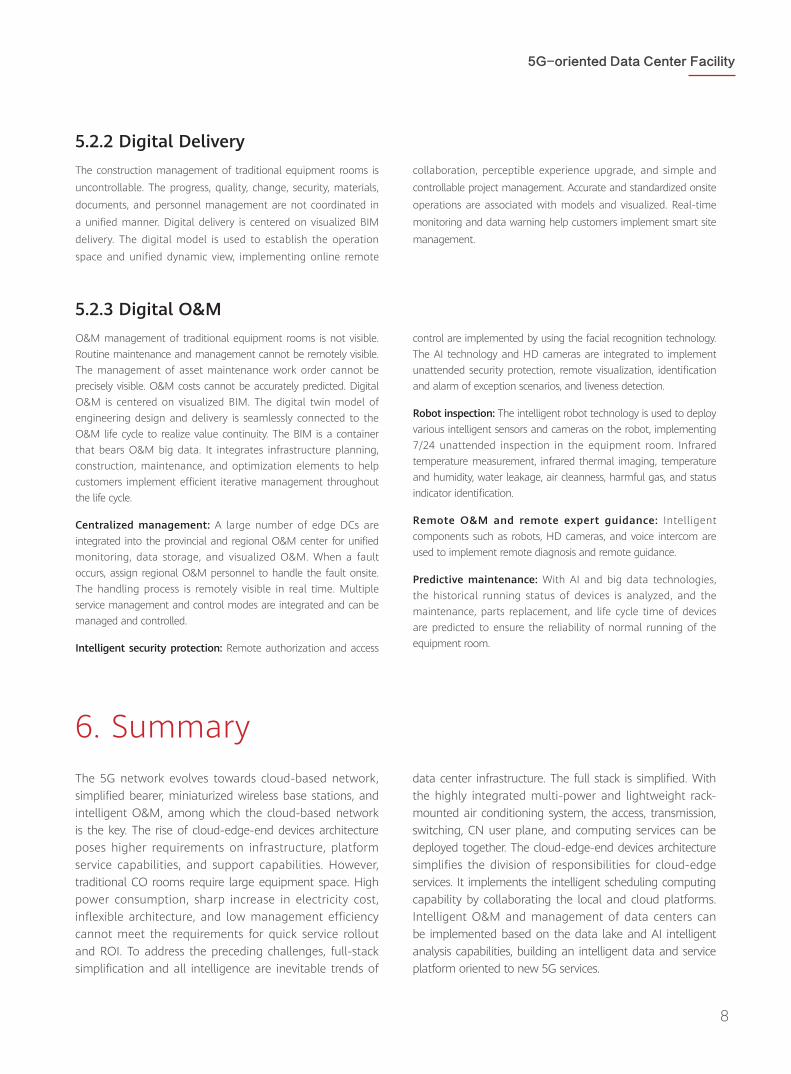
5.2.2 Digital DeliveryThe construction management of traditional equipment rooms is uncontrollable. The progress, quality, change, security, materials, documents, and personnel management are not coordinated in a unified manner. Digital delivery is centered on visualized BIM delivery. The digital model is used to establish the operation space and unified dynamic view, implementing online remote
collaboration, perceptible experience upgrade, and simple and controllable project management. Accurate and standardized onsite operations are associated with models and visualized. Real-time monitoring and data warning help customers implement smart site management.
5.2.3 Digital O&MO&M management of traditional equipment rooms is not visible. Routine maintenance and management cannot be remotely visible. The management of asset maintenance work order cannot be precisely visible. O&M costs cannot be accurately predicted. Digital O&M is centered on visualized BIM. The digital twin model of engineering design and delivery is seamlessly connected to the O&M life cycle to realize value continuity. The BIM is a container that bears O&M big data. It integrates infrastructure planning, construction, maintenance, and optimization elements to help customers implement efficient iterative management throughout the life cycle.
Centralized management: A large number of edge DCs are integrated into the provincial and regional O&M center for unified monitoring, data storage, and visualized O&M. When a fault occurs, assign regional O&M personnel to handle the fault onsite. The handling process is remotely visible in real time. Multiple service management and control modes are integrated and can be managed and controlled.
Intelligent security protection: Remote authorization and access
control are implemented by using the facial recognition technology. The AI technology and HD cameras are integrated to implement unattended security protection, remote visualization, identification and alarm of exception scenarios, and liveness detection.
Robot inspection: The intelligent robot technology is used to deploy various intelligent sensors and cameras on the robot, implementing 7/24 unattended inspection in the equipment room. Infrared temperature measurement, infrared thermal imaging, temperature and humidity, water leakage, air cleanness, harmful gas, and status indicator identification.
Remote O&M and remote expert guidance: Intelligent components such as robots, HD cameras, and voice intercom are used to implement remote diagnosis and remote guidance.
Predictive maintenance: With AI and big data technologies, the historical running status of devices is analyzed, and the maintenance, parts replacement, and life cycle time of devices are predicted to ensure the reliability of normal running of the equipment room.
The 5G network evolves towards cloud-based network, simplified bearer, miniaturized wireless base stations, and intelligent O&M, among which the cloud-based network is the key. The rise of cloud-edge-end devices architecture poses higher requirements on infrastructure, platform service capabilities, and support capabilities. However, traditional CO rooms require large equipment space. High power consumption, sharp increase in electricity cost, inflexible architecture, and low management efficiency cannot meet the requirements for quick service rollout and ROI. To address the preceding challenges, full-stack simplification and all intelligence are inevitable trends of
data center infrastructure. The full stack is simplified. With the highly integrated multi-power and lightweight rack-mounted air conditioning system, the access, transmission, switching, CN user plane, and computing services can be deployed together. The cloud-edge-end devices architecture simplifies the division of responsibilities for cloud-edge services. It implements the intelligent scheduling computing capability by collaborating the local and cloud platforms. Intelligent O&M and management of data centers can be implemented based on the data lake and AI intelligent analysis capabilities, building an intelligent data and service platform oriented to new 5G services.
6. Summary

HUAWEI TECHNOLOGIES CO., LTD.Huawei Industrial BaseBantian LonggangShenzhen 518129, P. R. ChinaTel: +86-755-28780808www.huawei.com
GENERAL DISCLAIMERThe information in this document may contain predictive statement including, without limitation, statements regarding the future financial and operating results, future product portfolios, new technologies, etc. There are a number of factors that could cause actual results and developments to differ materially from those expressed or implied in the predictive statements. Therefore, such information is provided for reference purpose only and constitutes neither an offer nor an acceptance. Huawei may change the information at any time without notice.
Copyright © 2019 HUAWEI TECHNOLOGIES CO., LTD. All Rights Reserved.No part of this document may be reproduced or transmitted in any form or by any means without prior written consent of Huawei Technologies Co.,Ltd.
Tradememark Notice , , are trademarks or registered trademarks of Huawei Technologies Co.,Ltd.Other Trademarks, product, service and company names mentioned are the property of thier respective owners.